Copyright 2011 Bit Cauldron Corporation Page 1 of 24
User’s Manual – Optoma 3D-RF System: Optoma 3D-RF Glasses and Optoma 3D-
RF Emitter Contains Patent Pending software and technology from Bit Cauldron
Contient les logitiels de brevet en instance et la technologie de la compagnie Bit Cauldron
Optoma 3D-RF Emitter Manual The Optoma 3D-RF Emitter connects Optoma 3D-XL converter box to the Optoma 3D-RF Shutter Glasses
for the ultimate in 3D stereoscopic viewing. This document describes the features, connection, setup,
and operation of the Optoma 3D-RF Emitter with Optoma 3D-XL converter box.
Features RF synchronization for uninterruptable 3D glasses performance
Ready to watch compatibility with 3D Ready Optoma projectors with Optoma 3D-XL converter box
LED indicators assist with IR Sensor placement
Management Software enables Upgrade functionality for compatibility with future 3D TVs
Manual performance adjustment capability
Copyright 2011 Bit Cauldron Corporation Page 2 of 24
Connections
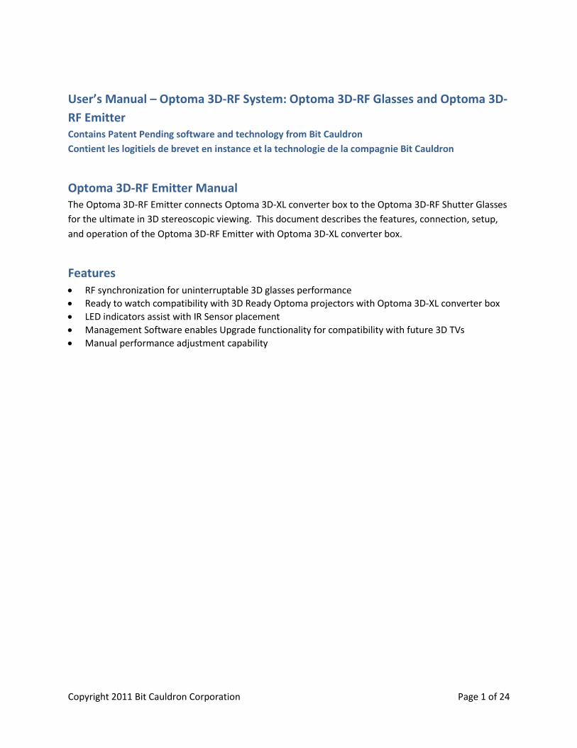
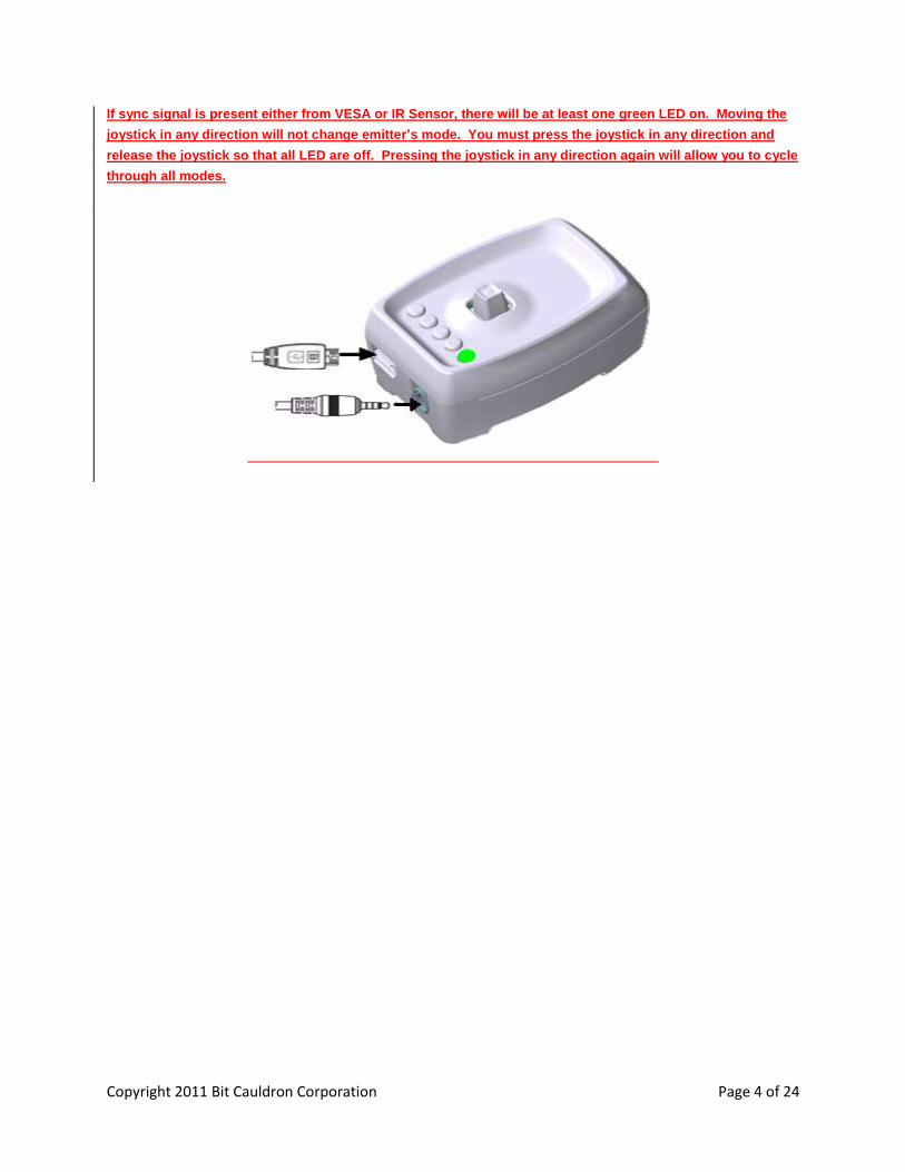
Optoma 3D-XL converter box with 3D Emitter Port 1: Connect the Optoma 3D-RF emitter to the Optoma 3D-XL converter box using the IR Emitter Port as shown below.
Basic Features
RF Communication of Synchronization Signal
RF communications enables the Optoma 3D-RF System to provide an awesome and uninterruptable 3D
viewing experience. Line of sight obstructions, emitter placement and viewer seating arrangements
have no impact on the performance of the emitter to glasses synchronization. Optimal seating distance
and viewing angle is determined by the capabilities of the 3D Ready Projector coupled to the Optoma
3D-XL converter box and 3D-RF System.
Copyright 2011 Bit Cauldron Corporation Page 3 of 24
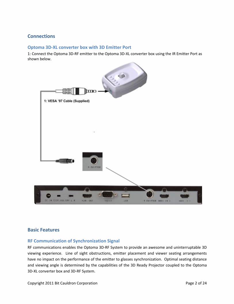
LED Indicators
The Optoma 3D-RF Emitter uses 5 multicolored LEDs
to indicate modes of operation or other information.
The LEDs are located on the top of the emitter close
to the joystick and display red, green, or orange.
Joystick
The Optoma 3D-RF Emitter uses a joystick to allow
the user to enable various modes and change
settings. The joystick has two axes and a center
button function. Function of the axes and buttons
are dependent on the operating mode as described
in following sections.
Modes of Operation
The Optoma 3D-RF Emitter has 5 modes of operation.
Normal
Sync Signal Status (Strength)
Manual Tuning of Glasses Performance
Pairing the Optoma 3D-RF Emitter with Optoma 3D-RF Glasses
Set Polarity
Accessing Modes
During normal operation, the joystick is used to
access different modes of operation. Press and
hold the joystick to cycle through the available
modes. Release the joystick to select a mode. In
any mode, the normal mode of operation
resumes after 60 seconds of inactivity with the
exception of Set Polarity mode. Set Polarity mode
will time out in 10 seconds.
Copyright 2011 Bit Cauldron Corporation Page 4 of 24
If sync signal is present either from VESA or IR Sensor, there will be at least one green LED on. Moving the
joystick in any direction will not change emitter’s mode. You must press the joystick in any direction and
release the joystick so that all LED are off. Pressing the joystick in any direction again will allow you to cycle
through all modes.
Copyright 2011 Bit Cauldron Corporation Page 5 of 24
Normal Operation Mode
During normal operating mode, the Optoma 3D-RF Emitter interprets 3D signals from the 3D-XL
converter box and controls the Optoma 3D-RF Series Shutter Glasses through RF. No LEDs are active.
Signal Status (Strength) Indicator Mode
The signal status (strength) indicator provides a visual signal status measurement. The number of lit
green LEDs indicates the quality of the sync signal, with more green LEDs equating to better Sync signal.
The LEDs will display a red moving pattern while the emitter is attempting to acquire a 3D signal and
until a signal is found.
Manual Performance Tuning Mode
The Optoma 3D-RF Emitter and Optoma 3D-RF Shutter Glasses are preprogrammed to work with a wide
variety of TVs and 3D content. The manual performance tuning mode enables the 3D system
performance to be fine tuned. Warning, use of this feature can result in improper or undesirable
operation.
3D Emitter & Glasses Pairing Mode
In environments where more than one Optoma 3D-RF Emitter is present, Optoma 3D-RF Glasses should
be paired with the emitter to ensure proper operation. This mode also involves the Optoma 3D-RF
Glasses and is described in greater detail in a subsequent section.
Set Polarity Mode
This mode allows manual setting of lens polarity. During normal operation left lens will open when
rising sync edge is detected. Polarity can be reversed so that right lens will open when rising sync edge
is detected.
Factory Defaults Mode
In the event that the Optoma 3D-RF Emitter is not working properly and other troubleshooting methods
have failed, use the Reset to Factory Defaults mode to attempt recovery of proper operation. Warning:
Any tuning done using Manual Performance Tuning will be erased.
Connecting the Optoma 3D-RF Emitter to Optoma 3D-XL converter box
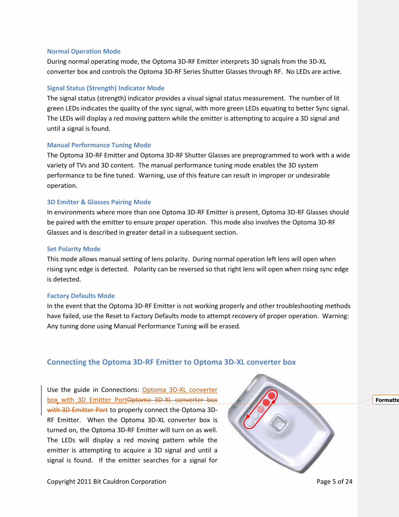
Use the guide in Connections: Optoma 3D-XL converter
box with 3D Emitter PortOptoma 3D-XL converter box
with 3D Emitter Port to properly connect the Optoma 3D-
RF Emitter. When the Optoma 3D-XL converter box is
turned on, the Optoma 3D-RF Emitter will turn on as well.
The LEDs will display a red moving pattern while the
emitter is attempting to acquire a 3D signal and until a
signal is found. If the emitter searches for a signal for
Formatted: Font: (Asian) Korean
Copyright 2011 Bit Cauldron Corporation Page 6 of 24
longer than 60 seconds, a signal is not found. Ensure that the 3D ready projector is in 3D mode. In
addition to setting the 3D ready projector in 3D mode, you must also have 3D content playing in order
to find 3D signal (LED’s turn green.)
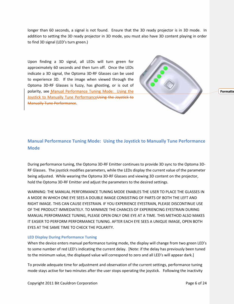
Upon finding a 3D signal, all LEDs will turn green for
approximately 60 seconds and then turn off. Once the LEDs
indicate a 3D signal, the Optoma 3D-RF Glasses can be used
to experience 3D. If the image when viewed through the
Optoma 3D-RF Glasses is fuzzy, has ghosting, or is out of
polarity, see Manual Performance Tuning Mode: Using the
Joystick to Manually Tune PerformanceUsing the Joystick to
Manually Tune Performance.
Manual Performance Tuning Mode: Using the Joystick to Manually Tune Performance
Mode
During performance tuning, the Optoma 3D-RF Emitter continues to provide 3D sync to the Optoma 3D-
RF Glasses. The joystick modifies parameters, while the LEDs display the current value of the parameter
being adjusted. While wearing the Optoma 3D-RF Glasses and viewing 3D content on the projector,
hold the Optoma 3D-RF Emitter and adjust the parameters to the desired settings.
WARNING: THE MANUAL PERFORMANCE TUNING MODE ENABLES THE USER TO PLACE THE GLASSES IN
A MODE IN WHICH ONE EYE SEES A DOUBLE IMAGE CONSISTING OF PARTS OF BOTH THE LEFT AND
RIGHT IMAGE. THIS CAN CAUSE EYESTRAIN. IF YOU EXPERIENCE EYESTRAIN, PLEASE DISCONTINUE USE
OF THE PRODUCT IMMEDIATELY. TO MINIMIZE THE CHANCES OF EXPERIENCING EYESTRAIN DURING
MANUAL PERFORMANCE TUNING, PLEASE OPEN ONLY ONE EYE AT A TIME. THIS METHOD ALSO MAKES
IT EASIER TO PERFORM PERFORMANCE TUNING. AFTER EACH EYE SEES A UNIQUE IMAGE, OPEN BOTH
EYES AT THE SAME TIME TO CHECK THE POLARITY.
LED Display During Performance Tuning
When the device enters manual performance tuning mode, the display will change from two green LED’s
to some number of red LED’s indicating the current delay. [Note: if the delay has previously been tuned
to the minimum value, the displayed value will correspond to zero and all LED’s will appear dark.]
To provide adequate time for adjustment and observation of the current settings, performance tuning
mode stays active for two minutes after the user stops operating the joystick. Following the inactivity
Formatted: Font:
Copyright 2011 Bit Cauldron Corporation Page 7 of 24
period, the performance tuning settings will be saved and the Optoma 3D-RF Emitter will return to
normal operating mode.
See the appendix About Performance Tuning for a detailed explanation of shutter glass function and
performance tuning.
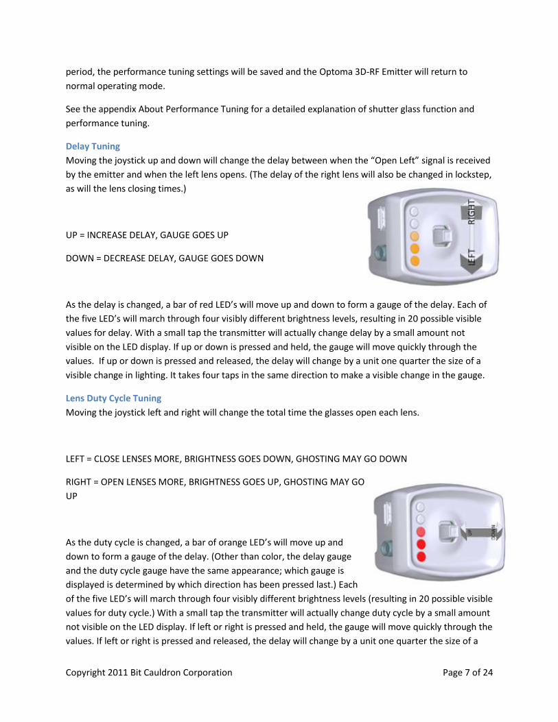
Delay Tuning
Moving the joystick up and down will change the delay between when the “Open Left” signal is received
by the emitter and when the left lens opens. (The delay of the right lens will also be changed in lockstep,
as will the lens closing times.)
UP = INCREASE DELAY, GAUGE GOES UP
DOWN = DECREASE DELAY, GAUGE GOES DOWN
As the delay is changed, a bar of red LED’s will move up and down to form a gauge of the delay. Each of
the five LED’s will march through four visibly different brightness levels, resulting in 20 possible visible
values for delay. With a small tap the transmitter will actually change delay by a small amount not
visible on the LED display. If up or down is pressed and held, the gauge will move quickly through the
values. If up or down is pressed and released, the delay will change by a unit one quarter the size of a
visible change in lighting. It takes four taps in the same direction to make a visible change in the gauge.
Lens Duty Cycle Tuning
Moving the joystick left and right will change the total time the glasses open each lens.
LEFT = CLOSE LENSES MORE, BRIGHTNESS GOES DOWN, GHOSTING MAY GO DOWN
RIGHT = OPEN LENSES MORE, BRIGHTNESS GOES UP, GHOSTING MAY GO
UP
As the duty cycle is changed, a bar of orange LED’s will move up and
down to form a gauge of the delay. (Other than color, the delay gauge
and the duty cycle gauge have the same appearance; which gauge is
displayed is determined by which direction has been pressed last.) Each
of the five LED’s will march through four visibly different brightness levels (resulting in 20 possible visible
values for duty cycle.) With a small tap the transmitter will actually change duty cycle by a small amount
not visible on the LED display. If left or right is pressed and held, the gauge will move quickly through the
values. If left or right is pressed and released, the delay will change by a unit one quarter the size of a
Copyright 2011 Bit Cauldron Corporation Page 8 of 24
visible change in lighting. It takes four taps in the same direction to make a visible change in the gauge;
in certain lighting conditions a single tap may be visible as a change in brightness viewed through the
glasses.
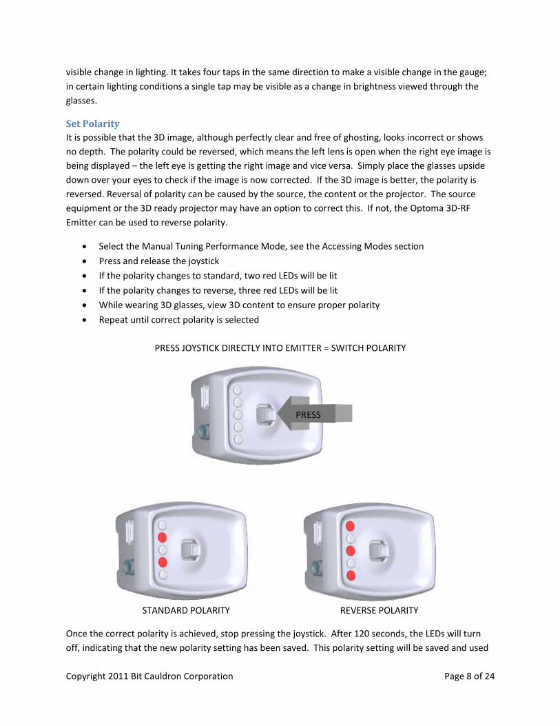
Set Polarity
It is possible that the 3D image, although perfectly clear and free of ghosting, looks incorrect or shows
no depth. The polarity could be reversed, which means the left lens is open when the right eye image is
being displayed – the left eye is getting the right image and vice versa. Simply place the glasses upside
down over your eyes to check if the image is now corrected. If the 3D image is better, the polarity is
reversed. Reversal of polarity can be caused by the source, the content or the projector. The source
equipment or the 3D ready projector may have an option to correct this. If not, the Optoma 3D-RF
Emitter can be used to reverse polarity.
Select the Manual Tuning Performance Mode, see the Accessing Modes section
Press and release the joystick
If the polarity changes to standard, two red LEDs will be lit
If the polarity changes to reverse, three red LEDs will be lit
While wearing 3D glasses, view 3D content to ensure proper polarity
Repeat until correct polarity is selected
PRESS JOYSTICK DIRECTLY INTO EMITTER = SWITCH POLARITY
STANDARD POLARITY REVERSE POLARITY
Once the correct polarity is achieved, stop pressing the joystick. After 120 seconds, the LEDs will turn
off, indicating that the new polarity setting has been saved. This polarity setting will be saved and used
PRESS

Copyright 2011 Bit Cauldron Corporation Page 9 of 24
until it is adjusted again or a factory reset is performed. The Optoma 3D-RF Emitter will return to Normal
Operation Mode.
More information about Performance Tuning is found in the section About Performance Tuning.
Polarity can also be changed in “Set Polarity mode”, see Accessing Modes section on page 4 to set this
mode. Description of “Set Polarity mode” is on page 11.
Copyright 2011 Bit Cauldron Corporation Page 10 of 24
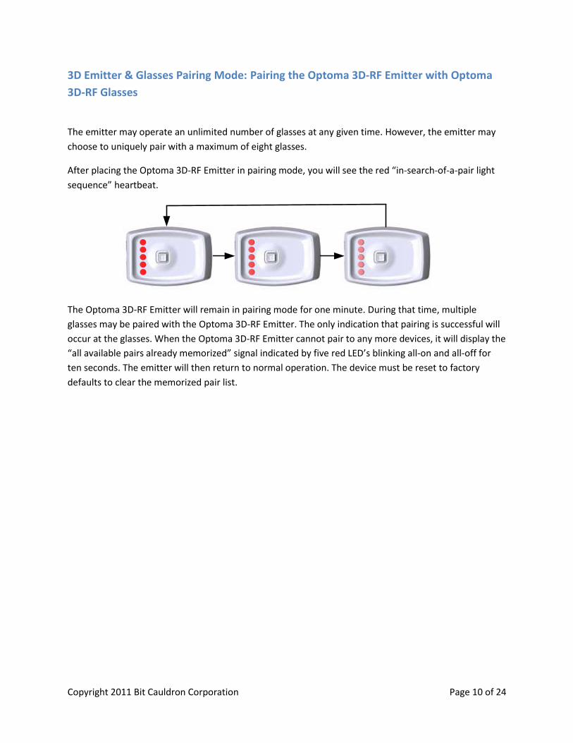
3D Emitter & Glasses Pairing Mode: Pairing the Optoma 3D-RF Emitter with Optoma
3D-RF Glasses
The emitter may operate an unlimited number of glasses at any given time. However, the emitter may
choose to uniquely pair with a maximum of eight glasses.
After placing the Optoma 3D-RF Emitter in pairing mode, you will see the red “in-search-of-a-pair light
sequence” heartbeat.
The Optoma 3D-RF Emitter will remain in pairing mode for one minute. During that time, multiple
glasses may be paired with the Optoma 3D-RF Emitter. The only indication that pairing is successful will
occur at the glasses. When the Optoma 3D-RF Emitter cannot pair to any more devices, it will display the
“all available pairs already memorized” signal indicated by five red LED’s blinking all-on and all-off for
ten seconds. The emitter will then return to normal operation. The device must be reset to factory
defaults to clear the memorized pair list.
Copyright 2011 Bit Cauldron Corporation Page 11 of 24
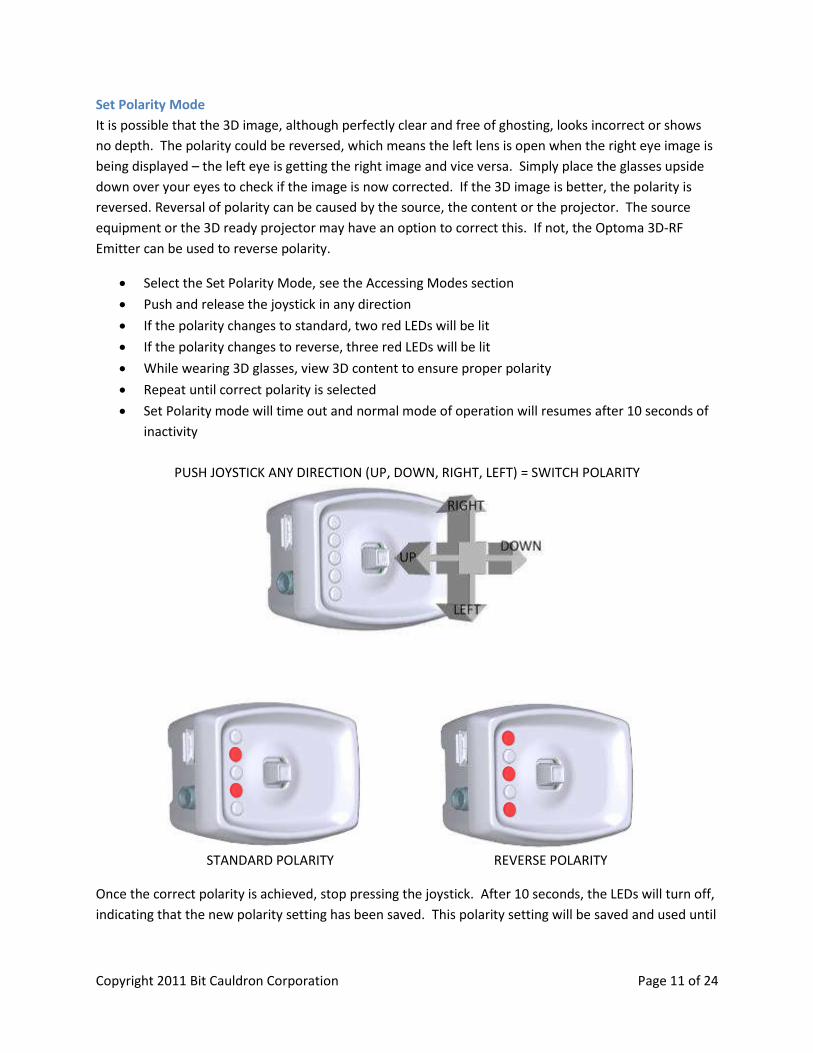
Set Polarity Mode
It is possible that the 3D image, although perfectly clear and free of ghosting, looks incorrect or shows
no depth. The polarity could be reversed, which means the left lens is open when the right eye image is
being displayed – the left eye is getting the right image and vice versa. Simply place the glasses upside
down over your eyes to check if the image is now corrected. If the 3D image is better, the polarity is
reversed. Reversal of polarity can be caused by the source, the content or the projector. The source
equipment or the 3D ready projector may have an option to correct this. If not, the Optoma 3D-RF
Emitter can be used to reverse polarity.
Select the Set Polarity Mode, see the Accessing Modes section
Push and release the joystick in any direction
If the polarity changes to standard, two red LEDs will be lit
If the polarity changes to reverse, three red LEDs will be lit
While wearing 3D glasses, view 3D content to ensure proper polarity
Repeat until correct polarity is selected
Set Polarity mode will time out and normal mode of operation will resumes after 10 seconds of
inactivity
PUSH JOYSTICK ANY DIRECTION (UP, DOWN, RIGHT, LEFT) = SWITCH POLARITY
STANDARD POLARITY REVERSE POLARITY
Once the correct polarity is achieved, stop pressing the joystick. After 10 seconds, the LEDs will turn off,
indicating that the new polarity setting has been saved. This polarity setting will be saved and used until

Copyright 2011 Bit Cauldron Corporation Page 12 of 24
it is adjusted again or a factory reset is performed. The Optoma 3D-RF Emitter will return to Normal
Operation Mode.
More information about Performance Tuning is found in the section About Performance Tuning.
Copyright 2011 Bit Cauldron Corporation Page 13 of 24
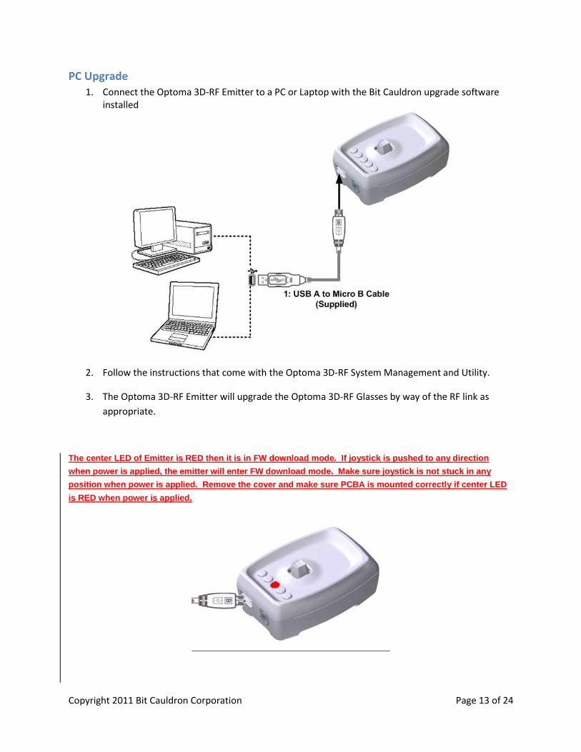
PC Upgrade
1. Connect the Optoma 3D-RF Emitter to a PC or Laptop with the Bit Cauldron upgrade software installed
2. Follow the instructions that come with the Optoma 3D-RF System Management and Utility.
3. The Optoma 3D-RF Emitter will upgrade the Optoma 3D-RF Glasses by way of the RF link as
appropriate.
The center LED of Emitter is RED then it is in FW download mode. If joystick is pushed to any direction
when power is applied, the emitter will enter FW download mode. Make sure joystick is not stuck in any
position when power is applied. Remove the cover and make sure PCBA is mounted correctly if center LED
is RED when power is applied.
Copyright 2011 Bit Cauldron Corporation Page 14 of 24
Optoma 3D-RF Glasses Manual The Optoma 3D-RF Shutter Glasses function with the Optoma 3D-RF Emitter and 3D-XL converter box
connected to 3D ready projector to provide the ultimate in 3D stereoscopic viewing. This document
describes the features, connection, setup, and operation of the Optoma 3D-RF Shutter Glasses.
Features RF synchronization for uninterruptable 3D glasses performance
50 to 240 Hz capable for today’s and future 3D TVs
High contrast ratio, high uniformity and fast response time for excellent 3D experience
Rechargeable battery provides up to 60 hours 3D viewing per charge
Battery charge indicator lets you know remaining operating time
Auto Upgrade ensures continued proper operation
Using the Optoma 3D-RF Glasses
Battery Charging
To charge the Optoma 3D-RF, use the included Micro-USB cable. One end of the cable attaches to the
MicroUSB port on the bottom of the left earpiece of the glasses. The other end of the cable may be
attached to any USB A-type port, such as a port on a USB hub, a computer, or the back of 3D-XL
converter box. If attached to a computer, the Optoma 3D-RF will use the computer only to receive
power; the glasses will not appear as a device visible to Windows, Mac or other operating systems. The
USB cable may also be attached to a USB charger or a phone charger with the identical connector. The
Optoma 3D-RF will charge a completely dead battery in less than three hours. The Optoma 3D-RF may
be operated while charging.
The Optoma 3D-RF battery is designed to operate approximately 60 hours on a full charge. The glasses
will consume more power as needed to maintain ultra-high reliability, so battery life is a function of
many factors, including how much interference from 2.4 GHz devices like wireless routers must be
compensated. Under the most adverse conditions, your glasses should operate flawlessly while battery
life will be reduced to around 15 hours (examples of “most adverse conditions” include trade shows or
placing the glasses on a 2.4 GHz router performing continuous full-rate blasting on an interfering
channel).
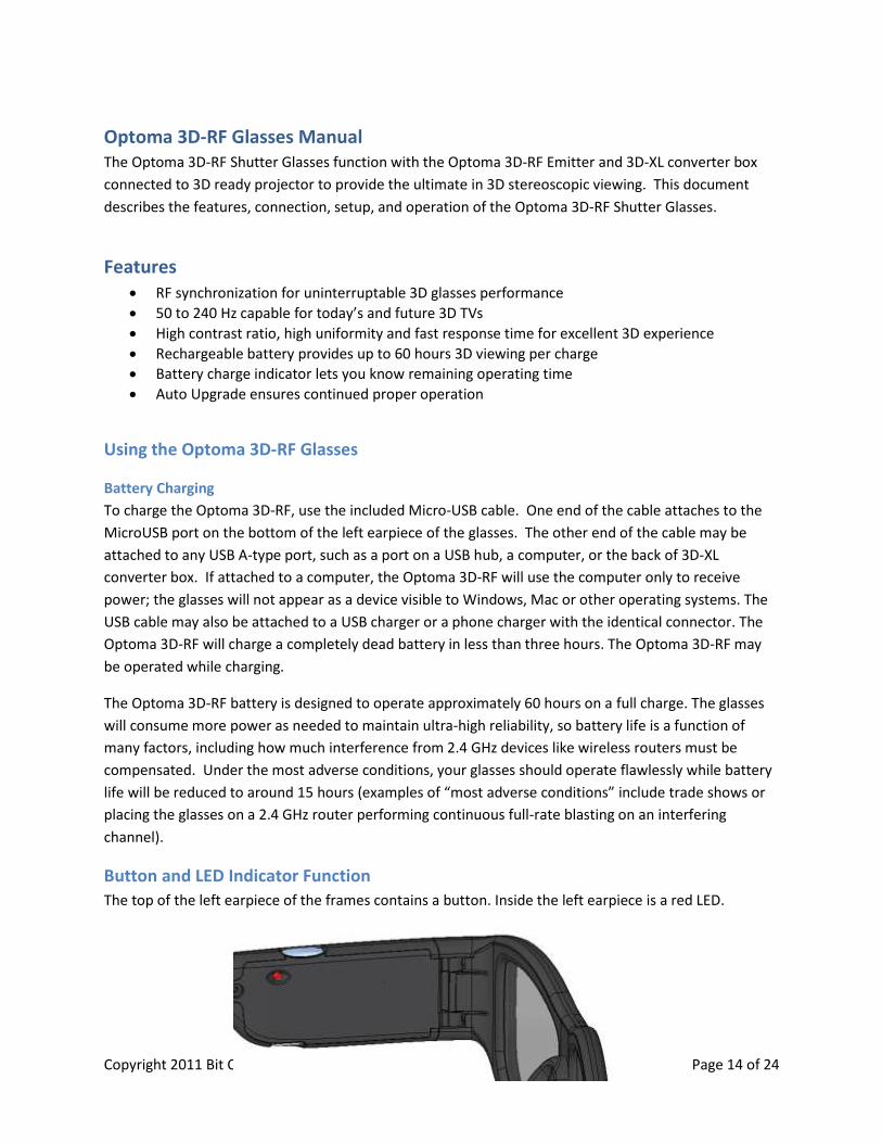
Button and LED Indicator Function
The top of the left earpiece of the frames contains a button. Inside the left earpiece is a red LED.
Copyright 2011 Bit Cauldron Corporation Page 15 of 24
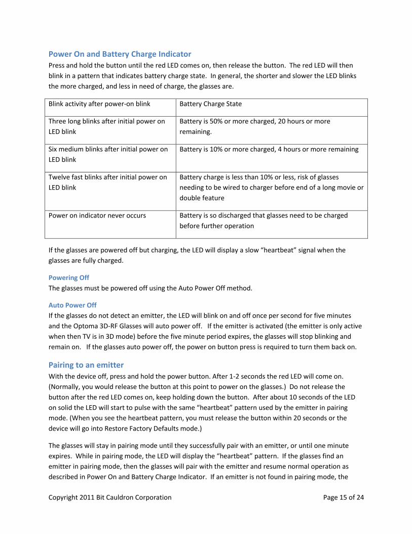
Power On and Battery Charge Indicator
Press and hold the button until the red LED comes on, then release the button. The red LED will then
blink in a pattern that indicates battery charge state. In general, the shorter and slower the LED blinks
the more charged, and less in need of charge, the glasses are.
Blink activity after power-on blink Battery Charge State
Three long blinks after initial power on
LED blink
Battery is 50% or more charged, 20 hours or more
remaining.
Six medium blinks after initial power on
LED blink
Battery is 10% or more charged, 4 hours or more remaining
Twelve fast blinks after initial power on
LED blink
Battery charge is less than 10% or less, risk of glasses
needing to be wired to charger before end of a long movie or
double feature
Power on indicator never occurs Battery is so discharged that glasses need to be charged
before further operation
If the glasses are powered off but charging, the LED will display a slow “heartbeat” signal when the
glasses are fully charged.
Powering Off
The glasses must be powered off using the Auto Power Off method.
Auto Power Off
If the glasses do not detect an emitter, the LED will blink on and off once per second for five minutes
and the Optoma 3D-RF Glasses will auto power off. If the emitter is activated (the emitter is only active
when then TV is in 3D mode) before the five minute period expires, the glasses will stop blinking and
remain on. If the glasses auto power off, the power on button press is required to turn them back on.
Pairing to an emitter
With the device off, press and hold the power button. After 1-2 seconds the red LED will come on.
(Normally, you would release the button at this point to power on the glasses.) Do not release the
button after the red LED comes on, keep holding down the button. After about 10 seconds of the LED
on solid the LED will start to pulse with the same “heartbeat” pattern used by the emitter in pairing
mode. (When you see the heartbeat pattern, you must release the button within 20 seconds or the
device will go into Restore Factory Defaults mode.)
The glasses will stay in pairing mode until they successfully pair with an emitter, or until one minute
expires. While in pairing mode, the LED will display the “heartbeat” pattern. If the glasses find an
emitter in pairing mode, then the glasses will pair with the emitter and resume normal operation as
described in Power On and Battery Charge Indicator. If an emitter is not found in pairing mode, the
Copyright 2011 Bit Cauldron Corporation Page 16 of 24
glasses will not operate but will continue to display the “heartbeat” pattern until the emitter is placed
into pairing mode, at which point the glasses will pair and begin normal operating mode immediately. If
the emitter is not placed in pairing mode, the glasses will stay in pairing mode for one minute and then
will power down.
Paired and unpaired glasses
Out of the box, the glasses are unpaired. The glasses will begin operating with the first active emitter
they recognize. (An emitter is active when it is on and receives a 3D signal from 3D-XL converter box
with 3D ready projector displaying 3D content.) Unpaired glasses will continue to operate only with the
same emitter they started operating with until they are powered down. If unpaired glasses are being
used with an emitter that gets turned off, the glasses will auto power down, even if a different emitter is
on or is turned on.
Unpaired glasses will look for the emitter found during the last use. If the previously found emitter is
not active, the glasses will start operating with the next emitter found.
Unpaired glasses are convenient if you plan on taking your glasses to your friend’s house. Simply power
down your glasses and bring them to your friend’s house. When you power your glasses back up, it will
wait one second for your emitter and then start using your friend’s emitter. The process is reversed
when you bring your glasses home.
Paired glasses will not use the signal from your friend’s emitter. Once paired, Optoma 3D-RF Glasses will
only recognize and synchronize with the emitter the glasses are paired to. This is useful if there are
multiple emitters within range and you want to be certain that a pair of glasses is always associated with
the same emitter.
To pair glasses with a new emitter, simply put the glasses back in pairing mode along with the new
emitter. To put paired glasses back in unpaired mode, the glasses must be restored to factory defaults.
Firmware Upgrade The firmware version on the Optoma 3D-RF Glasses is designed to properly operate with the firmware
on the Optoma 3D-RF Emitter. Firmware on the glasses is upgraded as required by the emitter. When
the emitter is upgraded, new glasses firmware is loaded on the emitter. When glasses are powered on
and find the upgraded emitter, the emitter sends the new firmware to the glasses and they restart. This
process takes several seconds to complete. The glasses LED will blink slowly while the new firmware is
being received and written to memory. Once the upgrade is complete, the glasses will automatically
restart.
The firmware version can be restored to the factory installed version by restoring factory defaults.
Copyright 2011 Bit Cauldron Corporation Page 17 of 24
Restoring Factory Defaults
Restoring a pair of glasses to factory defaults restores the factory default settings and firmware. This
includes putting the glasses in the unpaired mode. Any firmware or other settings on the glasses will be
reapplied by the Optoma 3D-RF Emitter upon restart of the Optoma 3D-RF Glasses.
To restore a pair of glasses to factory defaults, start with the glasses turned off.
Press and hold down the button
The LED will go on solid after 1 second; keep holding down the button
After about 10 more seconds the LED will start pulsing indicating that the glasses are ready to
pair; keep holding down the button.
After about 20 more seconds the LED will start blinking rapidly. Release the button now. The
glasses will restore the factory default settings and firmware. This can take several seconds.
After the process is complete, the glasses will resume normal operation.
If you do not release the button within 20 seconds after the LED begins rapidly blinking, the glasses will
power off.
Copyright 2011 Bit Cauldron Corporation Page 18 of 24
About Performance Tuning
Basic Function of Shutter Glasses
Both movie theaters and home entertainment systems work together with glasses to allow a person to
look at a flat screen and see different images in the left and right eye, thus providing the information
needed to perceive depth. Seeing slightly different images in each eye is the basis of 3D perception.
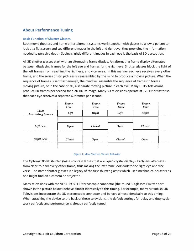
All 3D shutter glasses start with an alternating frame display. An alternating frame display alternates
between displaying frames for the left eye and frames for the right eye. Shutter glasses block the light of
the left frames from reaching the right eye, and vice versa. In this manner each eye receives every other
frame, and the series of still pictures is reassembled by the mind to produce a moving picture. When the
sequence of frames is sent fast enough, the mind will assemble the sequence of frames to form a
moving picture, or in the case of 3D, a separate moving picture in each eye. Many HDTV televisions
produce 60 frames per second for a 2D HDTV image. Many 3D televisions operate at 120 Hz or faster so
that each eye receives a separate 60 frames per second.
FrameOne
FrameTwo
FrameThree
FrameFour
Ideal Alternating Frames
Left Lens
Right Lens
Left Right Left Right
Open Closed Open Closed
Open Closed OpenClosed
Figure 1: Ideal Shutter Glasses Behavior
The Optoma 3D-RF shutter glasses contain lenses that are liquid crystal displays. Each lens alternates
from clear-to-dark every other frame, thus making the left frame look dark to the right eye and vice
versa. The name shutter glasses is a legacy of the first shutter glasses which used mechanical shutters as
one might find on a camera or projector.
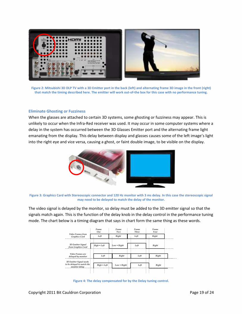
Many televisions with the VESA 1997-11 Stereoscopic connector (the round 3D glasses Emitter port
shown in the picture below) behave almost identically to this timing. For example, many Mitsubishi 3D
Televisions incorporate the 3D stereoscopic connector and behave almost identically to this timing.
When attaching the device to the back of these televisions, the default settings for delay and duty cycle,
work perfectly and performance is already perfectly tuned.
Copyright 2011 Bit Cauldron Corporation Page 19 of 24
Figure 2: Mitsubishi 3D DLP TV with a 3D Emitter port in the back (left) and alternating frame 3D image in the front (right) that match the timing described here. The emitter will work out-of-the box for this case with no performance tuning.
Eliminate Ghosting or Fuzziness
When the glasses are attached to certain 3D systems, some ghosting or fuzziness may appear. This is
unlikely to occur when the Infra-Red receiver was used. It may occur in some computer systems where a
delay in the system has occurred between the 3D Glasses Emitter port and the alternating frame light
emanating from the display. This delay between display and glasses causes some of the left image’s light
into the right eye and vice versa, causing a ghost, or faint double image, to be visible on the display.
Figure 3: Graphics Card with Stereoscopic connector and 120 Hz monitor with 3 ms delay. In this case the stereoscopic signal may need to be delayed to match the delay of the monitor.
The video signal is delayed by the monitor, so delay must be added to the 3D emitter signal so that the
signals match again. This is the function of the delay knob in the delay control in the performance tuning
mode. The chart below is a timing diagram that says in chart form the same thing as these words.
FrameOne
FrameTwo
FrameThree
FrameFour
Video Frames from Graphics Card
3D Emitter Signal from Graphics Card
Video Frames are delayed by monitor
3D Emitter Signal needs to be delayed to match the
monitor delay
Left Right Left Right
High = Left Low = Right Left Right
Left Right Left Right
High = Left Low = Right Left Right
Figure 4: The delay compensated for by the Delay tuning control.
Copyright 2011 Bit Cauldron Corporation Page 20 of 24
In engineering terms, the total time of one left frame and one right frame can be measured as 360
degrees. The delay control is centered at no delay and can add zero to 90 degrees. To add 90 to 180
degrees of delay, push the joystick to reverse and then adjust delay again.
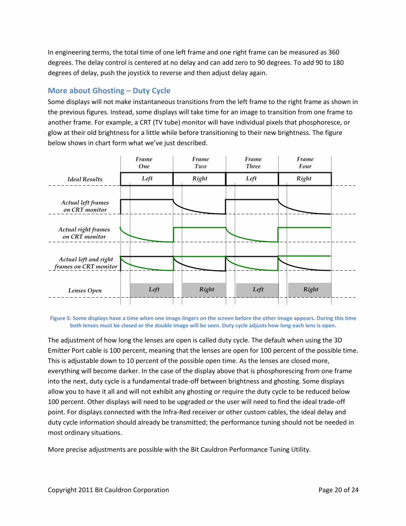
More about Ghosting – Duty Cycle
Some displays will not make instantaneous transitions from the left frame to the right frame as shown in
the previous figures. Instead, some displays will take time for an image to transition from one frame to
another frame. For example, a CRT (TV tube) monitor will have individual pixels that phosphoresce, or
glow at their old brightness for a little while before transitioning to their new brightness. The figure
below shows in chart form what we’ve just described.
FrameOne
FrameTwo
FrameThree
FrameFour
Ideal Results
Actual left frames on CRT monitor
Actual right frameson CRT monitor
Lenses Open
Left Right Left Right
Actual left and right frames on CRT monitor
Left Right Left Right
Figure 5: Some displays have a time when one image lingers on the screen before the other image appears. During this time both lenses must be closed or the double image will be seen. Duty cycle adjusts how long each lens is open.
The adjustment of how long the lenses are open is called duty cycle. The default when using the 3D
Emitter Port cable is 100 percent, meaning that the lenses are open for 100 percent of the possible time.
This is adjustable down to 10 percent of the possible open time. As the lenses are closed more,
everything will become darker. In the case of the display above that is phosphorescing from one frame
into the next, duty cycle is a fundamental trade-off between brightness and ghosting. Some displays
allow you to have it all and will not exhibit any ghosting or require the duty cycle to be reduced below
100 percent. Other displays will need to be upgraded or the user will need to find the ideal trade-off
point. For displays connected with the Infra-Red receiver or other custom cables, the ideal delay and
duty cycle information should already be transmitted; the performance tuning should not be needed in
most ordinary situations.
More precise adjustments are possible with the Bit Cauldron Performance Tuning Utility.

Copyright 2011 Bit Cauldron Corporation Page 21 of 24
REGULATOR NOTICES
Optoma 3D-RF Glasses
Optoma 3D-RF Emitter
FCC COMPLIANCE THIS DEVICE COMPLIES WITH PART 15 OF THE FCC RULES. OPERATION IS SUBJECT TO THE FOLLOWING TWO CONDITIONS: (1) THIS DEVICE MAY NOT CAUSE HARMFUL INTERFERENCE, AND
Copyright 2011 Bit Cauldron Corporation Page 22 of 24
(2) TH IS DEVICE MUST ACCEPT ANY INTERFERENCE RECEIVED, INCLUDING INTERFERENCE THAT MAY CAUSE UNDESIRED OPERATION.
FCC ID: YN3-50007001 FCCID: YN3-01007001 CAUTION: Changes or modifications to this unit not expressly approved by the party responsible for
compliance could void the user's authority to operate the equipment.
Note: This equipment has been tested and found to comply with the limits for a Class B digital device,
pursuant to Part 15 of the FCC Rules. These limits are designed to provide reasonable protection against
harmful interference in a residential installation.
This equipment generates, uses and can radiate radio frequency energy and, if not installed and used in accordance with the instructions, may cause harmful interference to radio communications. However, there is no guarantee that interference will not occur in a particular installation. If this equipment does cause harmful interference to radio or television reception, which can be determined by turning the equipment off and on, the user is encouraged to try to correct the interference by one or more of the following measures:
Reorient or relocate the receiving antenna • Increase the separation between the equipment and receiver • Connect the equipment into an outlet on a circuit different from that to which the receiver is
connected • Consult the dealer or an experienced radio/TV technician for help
CANADA COMPLIANCE Industry Canada: 9186A-50007003 Industry Canada: 9186A -01007003 ICES -003: Digital Apparatus: Spectrum Management and Telecommunications Policy; Interference-Causing Equipment Standard. This Class B digital apparatus complies with Canadian ICES -003. Cet appareil numérique de la classe B est conforme à la norme NMB -003 du Canada.
CE WARNING CAUTION: ESD Sensitive parts. The Optoma 3D-RF Glasses are is susceptible to electro-static discharge (ESD). Under negative ESD the device may shut down but will self-recover, or resume operation after the ESD event.
Copyright 2011 Bit Cauldron Corporation Page 23 of 24
WARNING - SAFETY INFORMATION & PRECAUTIONS
FOR INDOOR USE ONLY. NOT FOR USE AS SUNGLASSES.
THE 3D KIT CONTAINS ELECTRONIC DEVICES AND THE FOLLOWING PRECAUTIONS SHOULD BE
FOLLOWED:
Do not wear 3D glasses for any other activity except viewing 3D pictures. These glasses will
degrade visual perception in normal situations and are only intended for 3D use. Do not
attempt to use as sunglasses.
Handle the lenses carefully, especially when cleaning as too much force can easily damage the
glass. Do not drop any unit or flex the glasses. When cleaning, do not soak or immerse or over
wet the glasses as these are electronic devices and moisture can damage or impair their
function.
Do not use chemicals containing alcohol, solvents or surfactants or chemicals such as wax,
benzene, thinner, lubricant or cleaners. These may result in discoloration or cracks on the
product surface and cause the indication labels to peel from the product surface. Use only fluids
and products designed for screen cleaning and use them in accordance with the manufacturer’s
recommendations.
IMPORTANT - REVIEW THE FOLLOWING WARNINGS REGARDING THE EFFECTS OF 3D VIEWING PRIOR TO
ENGAGING IN 3D VIEWING AND ENSURE YOU UNDERSTAND THE PRECAUTIONS AND POTENTIAL
IMPACTS THAT 3D VIEWING CAN HAVE ON YOU AND/OR YOUR CHILDREN.
Parental supervision is required especially when children or teenagers view 3D images. You may
wish to consult a physician before allowing young children to view 3D.
3D TV’S and other 3D display devices use high speed flashes of light to generate a 3D effect. The
light flash effect may produce seizures or epileptic seizures in certain individuals in addition to
the following -
o Some light patterns may cause viewers to experience an epileptic seizure or stroke upon
exposure to certain flashing images or light patterns contained in certain 3D television
pictures or 3D video games. You should consult a physician before viewing 3D material
if you or any of your relatives has a history of epilepsy or strokes.
o “Photosensitive epileptic seizures” (reaction to flashes of light) can be caused by an
undiagnosed condition even when family members have no history of epilepsy.
o If you experience any of the following symptoms immediately stop watching 3D pictures
and consult physician or other medical specialist: altered vision; lightheadedness;
dizziness; involuntary movement such as eye or muscle twitching; confusion; nausea;
loss of awareness of your surroundings; convulsions; muscle cramps;
and/or disorientation. Parent’s should monitor and discuss with their children the
Copyright 2011 Bit Cauldron Corporation Page 24 of 24
above symptoms. Children and teenagers may be more susceptible than adults to
experiencing these symptoms.
o Do not watch 3D picture when you feel incoherent, sleepy, tired or sick. Avoid watching
3D pictures for long periods of time. Take regular breaks, especially during long periods
of 3D viewing.
Watching TV while wearing 3D glasses for an extended period of time may cause headache,
fatigue or dizziness. Remove the glasses and stop watching TV immediately if you experience
this.
Some 3D pictures may startle viewers. Due to the immersive nature of 3D viewing some scenes
may cause viewers to reach out or react suddenly, to avoid these possibly dangerous reactions
the pregnant, young children, elderly, epileptic and those suffering from serious physical
conditions are advised to avoid watching 3D pictures.
You should not watch 3D pictures if you are under the influence of alcohol, suffer from sleep
deprivation or are in poor physical condition.
3D viewing is designed to be immersive. 3D glasses are designed to be worn only in a safe
environment. If you are startled or misconstrue the 3D image as real, you may move in surprise,
contact a nearby object or person and break nearby objects or injure yourself or others.
Do not use the 3D glasses for any purpose other than the purpose it was designed for. Wearing
the 3D glasses for any other purpose (as general spectacles, sunglasses, protective goggles, etc.)
may physically harm you or weaken your eyesight
Some lights, such as compact florescent, florescent, and LED lighting systems, may flicker at rates
that are not perceivable to the naked eye but perceivable when wearing 3D glasses. Some lights
that are particularly bright may also appear to flicker when observed with 3D glasses. DO NOT
look directly into bright lights whether or not you are wearing 3D glasses. If you observe lights
that flicker while wearing 3D glasses, discontinue use of the glasses immediately and turn off or
move the lights so that there is no visible flicker while watching 3D.
WARNING – FIRE AND INJURY
DO NOT puncture, pierce, damage, destroy, or modify the battery contained in the glasses. Puncturing
the battery may result in combustion or a fire, which could lead to severe burns and injury. DO NOT
expose the battery to hot or cold temperature extremes. If there are any signs of damage to the battery,
discontinue use of the glasses immediately.


![[XLS] · Web viewLG HS200 DLP PROJECTOR 87366 PJ-HS200G LG HS200G DLP PROJECTOR 87367 PJ-HX300G LG HX300G DLP PROJECTOR 87395 PJTX542-3D OPTOMA TX542-3D PROJECTOR 87398 PJ-PK301 OPTOMA](https://static.cupdf.com/doc/110x72/5af2f08b7f8b9ad061915cb9/xls-viewlg-hs200-dlp-projector-87366-pj-hs200g-lg-hs200g-dlp-projector-87367-pj-hx300g.jpg)