1
UNIT III
HEAT EXCHANGERS
3.1 Heat Exchangers: Regenerators and Recuperators
A heat exchanger is an equipment where heat energy is transferred from a
hot fluid to a colder fluid. The transfer of heat energy between the two fluids could
be carried out (i) either by direct mixing of the two fluids and the mixed fluids leave
at an intermediate temperature determined from the principles of conservation of
energy, (ii) or by transmission through a wall separating the two fluids.
3.2. Classification of Heat Exchangers
Heat exchangers are generally classified according to the relative directions
of hot and cold fluids:
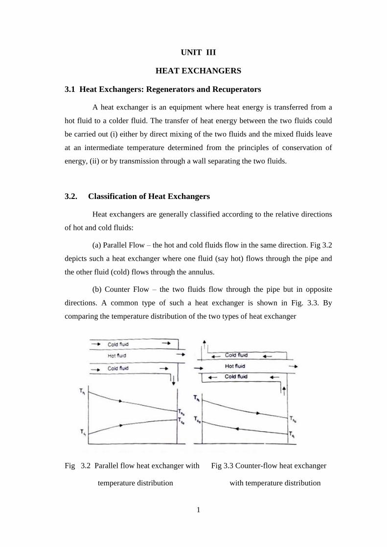
(a) Parallel Flow – the hot and cold fluids flow in the same direction. Fig 3.2
depicts such a heat exchanger where one fluid (say hot) flows through the pipe and
the other fluid (cold) flows through the annulus.
(b) Counter Flow – the two fluids flow through the pipe but in opposite
directions. A common type of such a heat exchanger is shown in Fig. 3.3. By
comparing the temperature distribution of the two types of heat exchanger
Fig 3.2 Parallel flow heat exchanger with Fig 3.3 Counter-flow heat exchanger
temperature distribution with temperature distribution
2
we find that the temperature difference between the two fluids is more
uniform in counter flow than in the parallel flow. Counter flow exchangers give the
maximum heat transfer rate and are the most favoured devices for heating or cooling
of fluids.
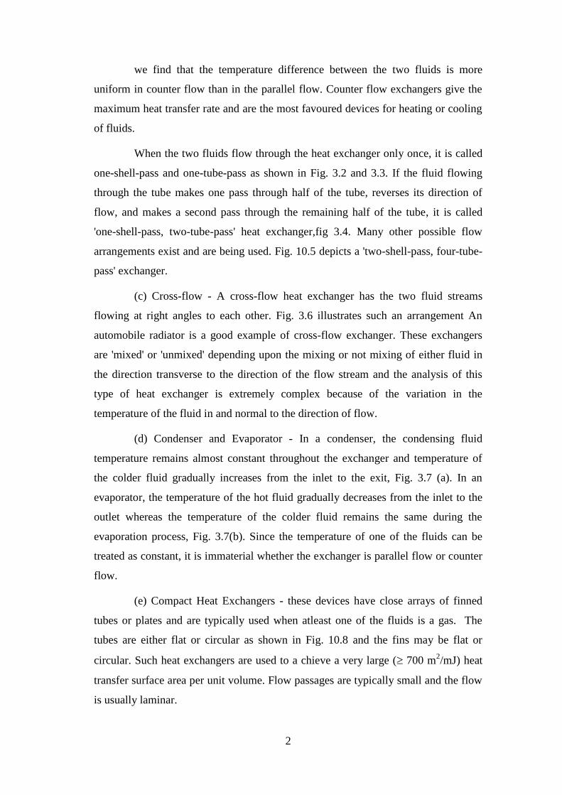
When the two fluids flow through the heat exchanger only once, it is called
one-shell-pass and one-tube-pass as shown in Fig. 3.2 and 3.3. If the fluid flowing
through the tube makes one pass through half of the tube, reverses its direction of
flow, and makes a second pass through the remaining half of the tube, it is called
'one-shell-pass, two-tube-pass' heat exchanger,fig 3.4. Many other possible flow
arrangements exist and are being used. Fig. 10.5 depicts a 'two-shell-pass, four-tube-
pass' exchanger.
(c) Cross-flow - A cross-flow heat exchanger has the two fluid streams
flowing at right angles to each other. Fig. 3.6 illustrates such an arrangement An
automobile radiator is a good example of cross-flow exchanger. These exchangers
are 'mixed' or 'unmixed' depending upon the mixing or not mixing of either fluid in
the direction transverse to the direction of the flow stream and the analysis of this
type of heat exchanger is extremely complex because of the variation in the
temperature of the fluid in and normal to the direction of flow.
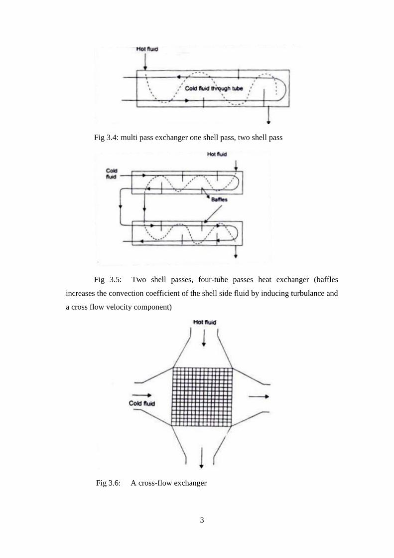
(d) Condenser and Evaporator - In a condenser, the condensing fluid
temperature remains almost constant throughout the exchanger and temperature of
the colder fluid gradually increases from the inlet to the exit, Fig. 3.7 (a). In an
evaporator, the temperature of the hot fluid gradually decreases from the inlet to the
outlet whereas the temperature of the colder fluid remains the same during the
evaporation process, Fig. 3.7(b). Since the temperature of one of the fluids can be
treated as constant, it is immaterial whether the exchanger is parallel flow or counter
flow.
(e) Compact Heat Exchangers - these devices have close arrays of finned
tubes or plates and are typically used when atleast one of the fluids is a gas. The
tubes are either flat or circular as shown in Fig. 10.8 and the fins may be flat or
circular. Such heat exchangers are used to a chieve a very large ( 700 m2/mJ) heat
transfer surface area per unit volume. Flow passages are typically small and the flow
is usually laminar.
3
Fig 3.4: multi pass exchanger one shell pass, two shell pass
Fig 3.5: Two shell passes, four-tube passes heat exchanger (baffles
increases the convection coefficient of the shell side fluid by inducing turbulance and
a cross flow velocity component)
Fig 3.6: A cross-flow exchanger
4
Fig. 3.8 Compact heat exchangers: (a) flat tubes, continuous plate fins, (b)
plate fin (single pass)
3.3. Expression for Log Mean Temperature Difference - Its
Characteristics
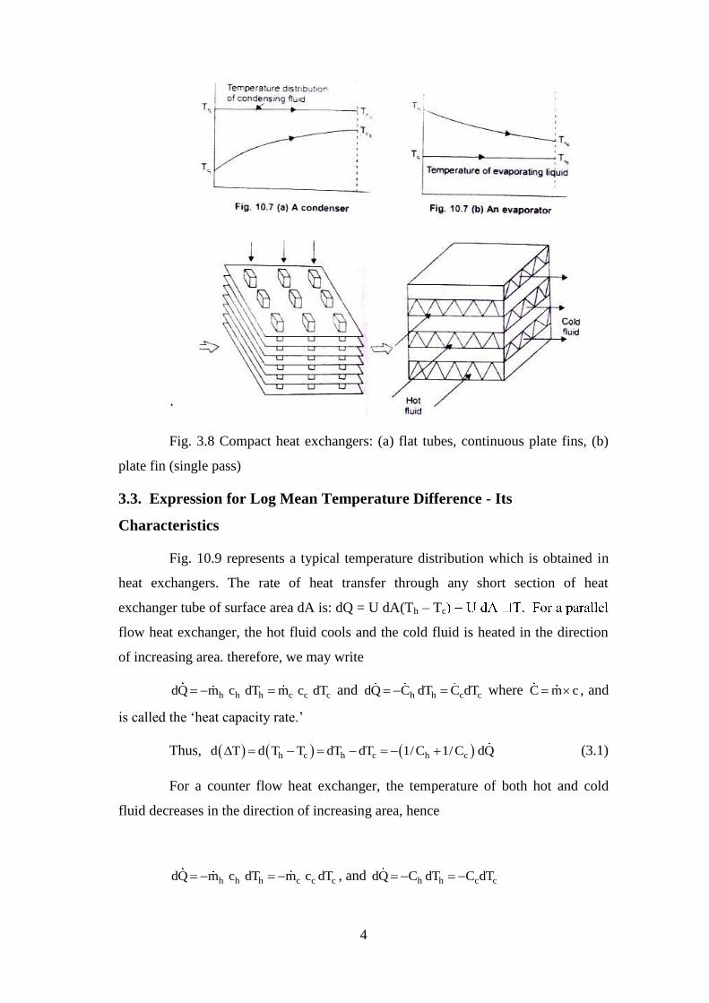
Fig. 10.9 represents a typical temperature distribution which is obtained in
heat exchangers. The rate of heat transfer through any short section of heat
exchanger tube of surface area dA is: dQ = U dA(Th – Tc
flow heat exchanger, the hot fluid cools and the cold fluid is heated in the direction
of increasing area. therefore, we may write
h h h c c cdQ m c dT m c dT and h h c cdQ C dT C dT where C m c , and
is called the ‘heat capacity rate.’
Thus, h c h c h cd T d T T dT dT 1/C 1/C dQ (3.1)
For a counter flow heat exchanger, the temperature of both hot and cold
fluid decreases in the direction of increasing area, hence
h h h c c cdQ m c dT m c dT , and h h c cdQ C dT C dT
5
or, h c h cd T dT dT 1/C 1/C dQ (3.2)
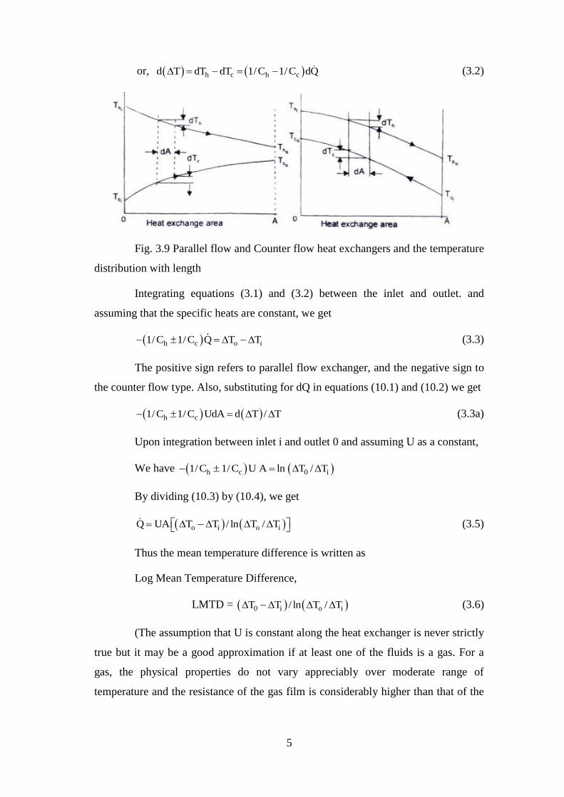
Fig. 3.9 Parallel flow and Counter flow heat exchangers and the temperature
distribution with length
Integrating equations (3.1) and (3.2) between the inlet and outlet. and
assuming that the specific heats are constant, we get
h c o i1/C 1/C Q T T (3.3)
The positive sign refers to parallel flow exchanger, and the negative sign to
the counter flow type. Also, substituting for dQ in equations (10.1) and (10.2) we get
h c1/C 1/C UdA d T / T (3.3a)
Upon integration between inlet i and outlet 0 and assuming U as a constant,
We have h c 0 i1/C 1/C U A ln T / T
By dividing (10.3) by (10.4), we get
o i o iQ UA T T / ln T / T (3.5)
Thus the mean temperature difference is written as
Log Mean Temperature Difference,
LMTD = 0 i o iT T / ln T / T (3.6)
(The assumption that U is constant along the heat exchanger is never strictly
true but it may be a good approximation if at least one of the fluids is a gas. For a
gas, the physical properties do not vary appreciably over moderate range of
temperature and the resistance of the gas film is considerably higher than that of the
6
metal wall or the liquid film, and the value of the gas film resistance effectively
determines the value of the overall heat transfer coefficient U.)
It is evident from Fig.1 0.9 that for parallel flow exchangers, the final
temperature of fluids lies between the initial values of each fluid whereas m counter
flow exchanger, the temperature of the colder fluid at exit is higher than the
temperature of the hot fluid at exit. Therefore, a counter flow exchanger provides a
greater temperature range, and the LMTD for a counter flow exchanger will be
higher than for a given rate of mass flow of the two fluids and for given temperature
changes, a counter flow exchanger will require less surface area.
3.4. Special Operating Conditions for Heat Exchangers
(i) Fig. 3.7a shows temperature distributions for a heat exchanger
(condenser) where the hot fluid has a much larger heat capacity rate, h h hC m c than
that of cold fluid, c c cC m c and therefore, the temperature of the hot fluid remains
almost constant throughout the exchanger and the temperature of the cold fluid
increases. The LMTD, in this case is not affected by whether the exchanger is a
parallel flow or counter flow.
(ii) Fig. 3.7b shows the temperature distribution for an evaporator. Here the
cold fluid expenses a change in phase and remains at a nearly uniform temperature
cC . The same effect would be achieved without phase change if c hC C ,
and the LMTD will remain the same for both parallel flow and counter flow
exchangers.
(iii) In a counter flow exchanger, when the heat capacity rate of uoth the
fluids are equal, c hC C , the temperature difference is the same all along the length
of the tube. And in that case, LMTD should be replaced by a bT T , and the
temperature profiles of the two fluids along Its length would be parallel straight lines.
(Since c c h h c cdQ C dT C dT ; dT dQ/C , and h hdT dQ/C
and, c h c hdT dT d dQ 1/C 1/C 0 (because c hC C )
fluids
7
along Its length would be parallel straight lines.)
3.5. LMTD for Cross-flow Heat Exchangers
LMTD given by Eq (10.6) is strictly applicable to either parallel flow or
counter flow exchangers. When we have multipass parallel flow or counter flow or
cross flow exchangers, LMTD is first calculated for single pass counter flow
exchanger and the mean temperature difference is obtained by multiplying the
LMTD with a correction factor F which takes care of the actual flow arrangement of
the exchanger. Or,
Q = U A F (LMTD) (3.7)
The correction factor F for different flow arrangements are obtained from
charts given in Fig. 3.10 (a, b, c, d).
3.6. Fouling Factors in Heat Exchangers
Heat exchanger walls are usually made of single materials. Sometimes the
walls are bimettalic (steel with aluminium cladding) or coated with a plastic as a
protection against corrosion, because, during normal operation surfaces are subjected
to fouling by fluid impurities, rust formation, or other reactions between the fluid and
the wall material. The deposition of a film or scale on the surface greatly increases
the resistance to heat transfer between the hot and cold fluids. And, a scale
coefficient of heat transfer h, is defined as:
os sR 1/ h A, C/ W or K/ W
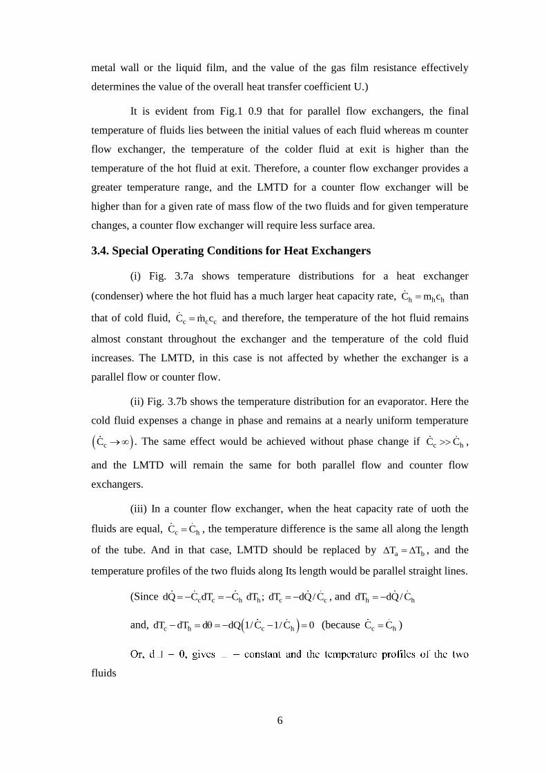
Fig 3.10(a) correctio factor to counter flow LMTD for heat exchanger with
8
one shell pass andtwo, or a muliple of two,tube passes
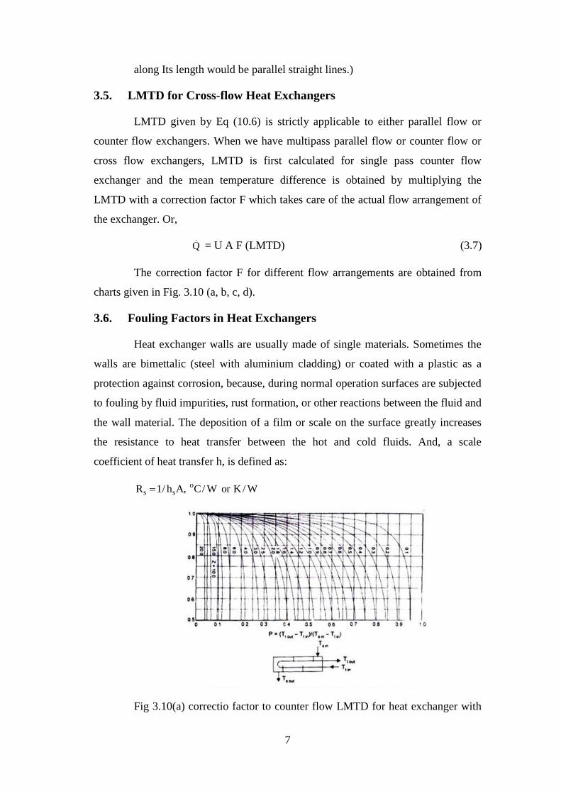
Fig 3.10 (b) Correction factor to counter flow LMTD for heat exchanger
with two shell passes and a multiple of two tube passes
where A is the area of the surface before scaling began and l/hs, is called
‘Fouling Factor'. Its value depends upon the operating temperature, fluid velocity,
and length of service of the heat exchanger. Table 10.1 gives the magnitude of l/h,
recommended for inclusion in the overall heat transfer coefficient for calculating the
required surface area of the exchanger
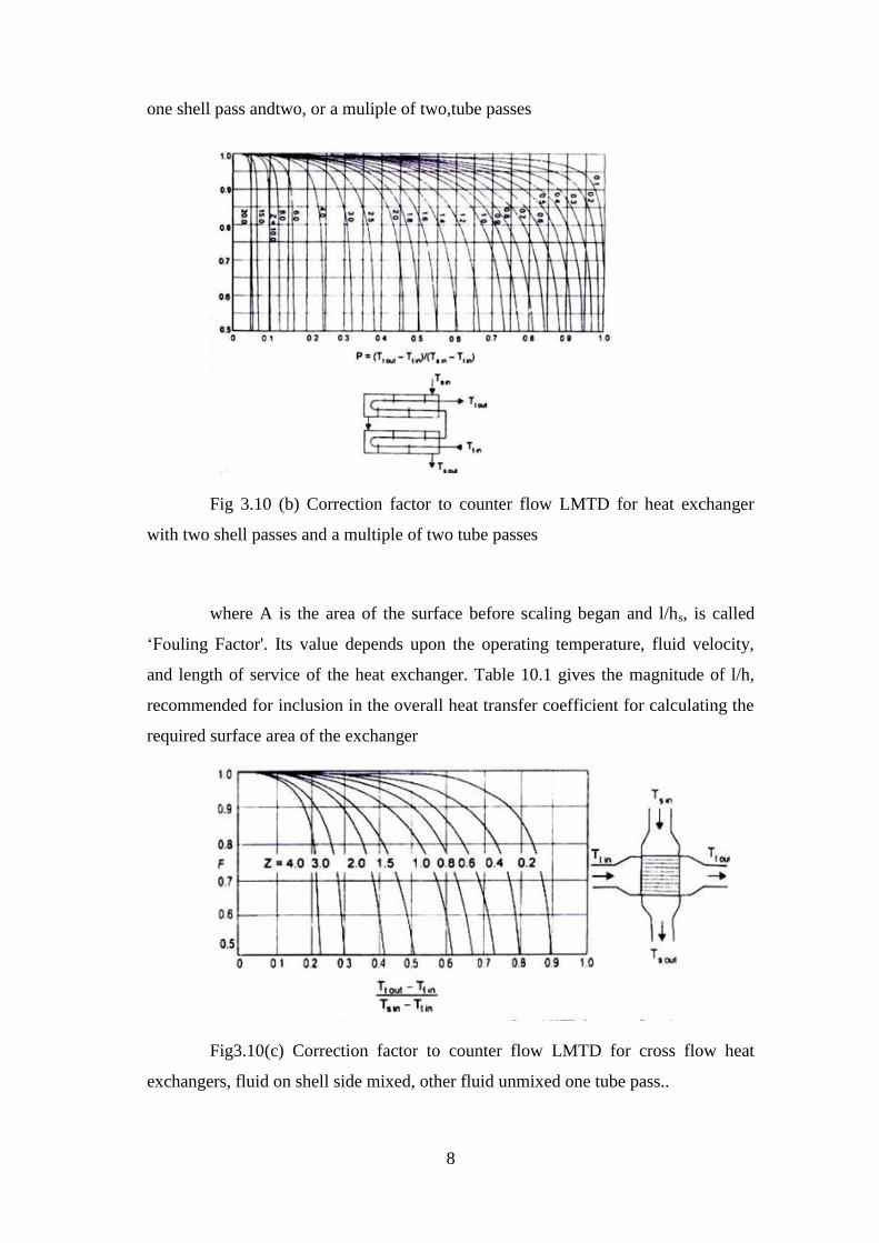
Fig3.10(c) Correction factor to counter flow LMTD for cross flow heat
exchangers, fluid on shell side mixed, other fluid unmixed one tube pass..
9
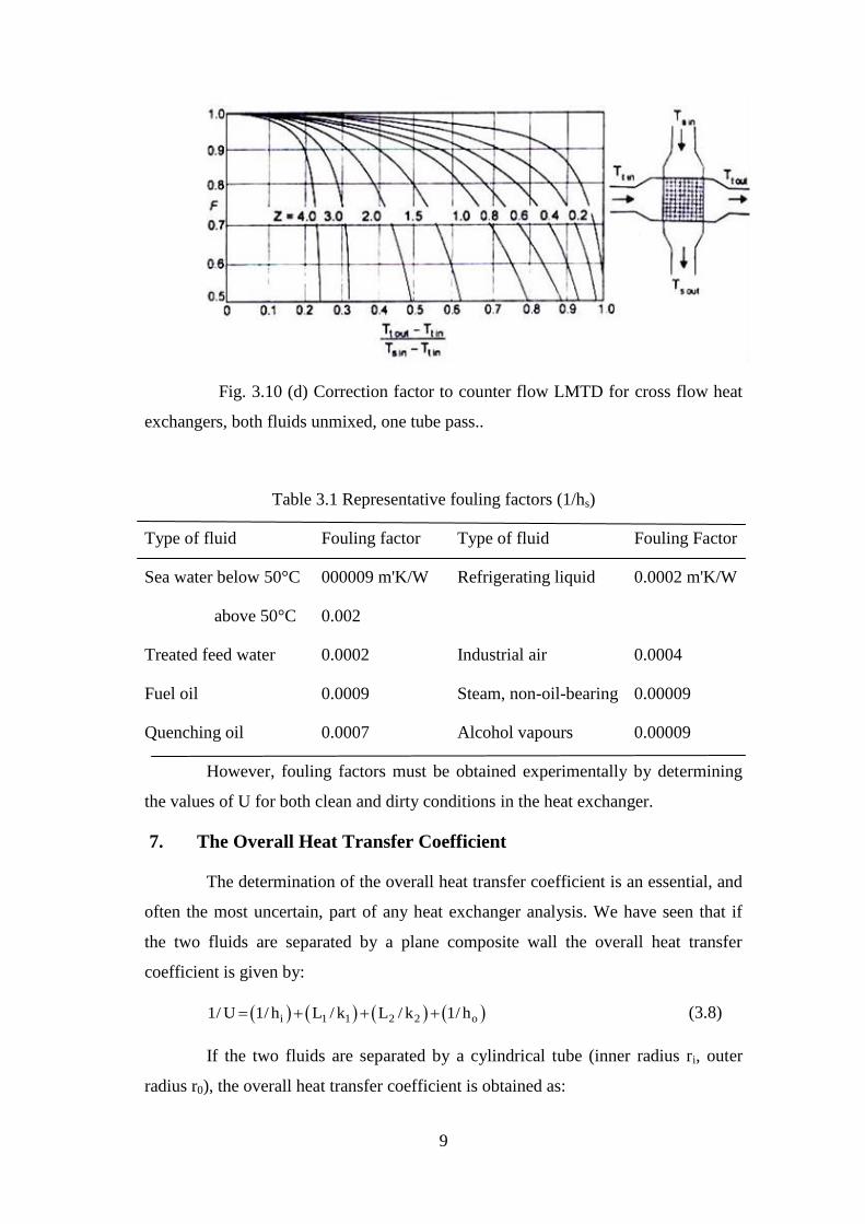
Fig. 3.10 (d) Correction factor to counter flow LMTD for cross flow heat
exchangers, both fluids unmixed, one tube pass..
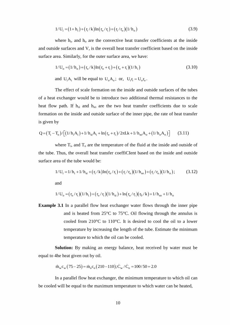
Table 3.1 Representative fouling factors (1/hs)
Type of fluid Fouling factor Type of fluid Fouling Factor
Sea water below 50°C 000009 m'K/W Refrigerating liquid 0.0002 m'K/W
above 50°C 0.002
Treated feed water 0.0002 Industrial air 0.0004
Fuel oil 0.0009 Steam, non-oil-bearing 0.00009
Quenching oil 0.0007 Alcohol vapours 0.00009
However, fouling factors must be obtained experimentally by determining
the values of U for both clean and dirty conditions in the heat exchanger.
7. The Overall Heat Transfer Coefficient
The determination of the overall heat transfer coefficient is an essential, and
often the most uncertain, part of any heat exchanger analysis. We have seen that if
the two fluids are separated by a plane composite wall the overall heat transfer
coefficient is given by:
i 1 1 2 2 o1/ U 1/ h L / k L / k 1/ h (3.8)
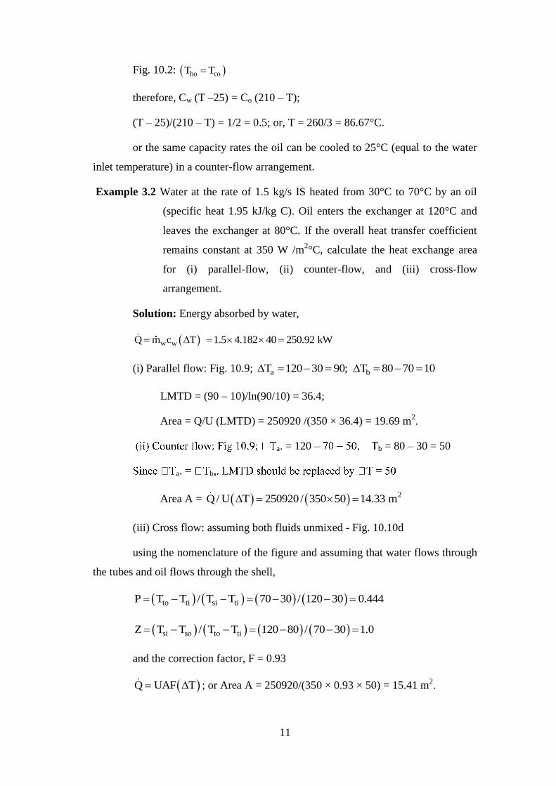
If the two fluids are separated by a cylindrical tube (inner radius ri, outer
radius r0), the overall heat transfer coefficient is obtained as:
10
i i i o i i o o1/ U 1 h r / k ln r / r r / r 1/ h (3.9)
where hi, and ho are the convective heat transfer coefficients at the inside
and outside surfaces and V, is the overall heat transfer coefficient based on the inside
surface area. Similarly, for the outer surface area, we have:
o o o o i o i i1/ U 1/ h r / k ln r r r r 1/ h (3.10)
and i iU A will be equal to o oU A ; or, i i o oU r U r .
The effect of scale formation on the inside and outside surfaces of the tubes
of a heat exchanger would be to introduce two additional thermal resistances to the
heat flow path. If hsi and hso are the two heat transfer coefficients due to scale
formation on the inside and outside surface of the inner pipe, the rate of heat transfer
is given by
i o i i si i o i so o o oQ T T / 1/ h A 1/ h A ln r r / 2 Lk 1/ h A 1/ h A (3.11)
where Ti, and To are the temperature of the fluid at the inside and outside of
the tube. Thus, the overall heat transfer coeffiCIent based on the inside and outside
surface area of the tube would be:
i i si i o i i o so i o o1/ U 1/ h 1/ h r / k ln r / r r / r 1/ h r / r 1/ h ; (3.12)
and
o o i i o i si o i 0 so o1/ U r / r 1/ h r / r 1/ h ln r / r r / k 1/ h 1/ h
Example 3.1 In a parallel flow heat exchanger water flows through the inner pipe
and is heated from 25°C to 75°C. Oil flowing through the annulus is
cooled from 210°C to 110°C. It is desired to cool the oil to a lower
temperature by increasing the length of the tube. Estimate the minimum
temperature to which the oil can be cooled.
Solution: By making an energy balance, heat received by water must be
equal to 4he heat given out by oil.
w w o o w om c 75 25 m c 210 110 ;C /C 100/50 2.0
In a parallel flow heat exchanger, the minimum temperature to which oil can
be cooled will be equal to the maximum temperature to which water can be heated,
11
Fig. 10.2: ho coT T
therefore, Cw (T –25) = Co (210 – T);
(T – 25)/(210 – T) = 1/2 = 0.5; or, T = 260/3 = 86.67°C.
or the same capacity rates the oil can be cooled to 25°C (equal to the water
inlet temperature) in a counter-flow arrangement.
Example 3.2 Water at the rate of 1.5 kg/s IS heated from 30°C to 70°C by an oil
(specific heat 1.95 kJ/kg C). Oil enters the exchanger at 120°C and
leaves the exchanger at 80°C. If the overall heat transfer coefficient
remains constant at 350 W /m2°C, calculate the heat exchange area
for (i) parallel-flow, (ii) counter-flow, and (iii) cross-flow
arrangement.
Solution: Energy absorbed by water,
w wQ m c T 1.5 4.182 40 250.92 kW
(i) Parallel flow: Fig. 10.9; a bT 120 30 90; T 80 70 10
LMTD = (90 – 10)/ln(90/10) = 36.4;
Area = Q/U (LMTD) = 250920 /(350 × 36.4) = 19.69 m2.
a. = 120 – b = 80 – 30 = 50
a b
Area A = 2Q/ U T 250920/ 350 50 14.33 m
(iii) Cross flow: assuming both fluids unmixed - Fig. 10.10d
using the nomenclature of the figure and assuming that water flows through
the tubes and oil flows through the shell,
to ti si tiP T T / T T 70 30 / 120 30 0.444
si so to tiZ T T / T T 120 80 / 70 30 1.0
and the correction factor, F = 0.93
Q UAF T ; or Area A = 250920/(350 × 0.93 × 50) = 15.41 m2.
12
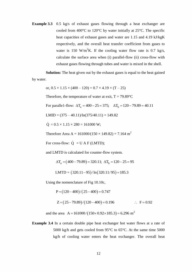
Example 3.3 0.5 kg/s of exhaust gases flowing through a heat exchanger are
cooled from 400°C to 120°C by water initially at 25°C. The specific
heat capacities of exhaust gases and water are 1.15 and 4.19 kJ/kgK
respectively, and the overall heat transfer coefficient from gases to
water is 150 W/m2K. If the cooling water flow rate is 0.7 kg/s,
calculate the surface area when (i) parallel-flow (ii) cross-flow with
exhaust gases flowing through tubes and water is mixed in the shell.
Solution: The heat given out by the exhaust gases is equal to the heat gained
by water.
or, 0.5 × 1.15 × (400 – 120) = 0.7 × 4.19 × (T – 25)
Therefore, the temperature of water at exit, T = 79.89°C
For paralle1-flow: aT 400 25 375; bT 120 79.89 40.11
LMID = (375 – 40.11)/ln(375/40.11) = 149.82
Q = 0.5 × 1.15 × 280 = 161000 W;
Therefore Area A = 161000/(150 × 149.82) = 7.164 m2
For cross-flow: Q = U A F (LMTD);
and LMTD is calculated for counter-flow system.
a bT 400 79.89 320.11; T 120 25 95
LMTD = 320.11 95 / ln 320.11/95 185.3
Using the nomenclature of Fig 10.10c,
P 120 400 / 25 400 0.747
Z 25 79.89 / 120 400 0.196 F 0.92
and the area 2A 161000/ 150 0.92 185.3 6.296 m
Example 3.4 In a certain double pipe heat exchanger hot water flows at a rate of
5000 kg/h and gets cooled from 95°C to 65°C. At the same time 5000
kg/h of cooling water enters the heat exchanger. The overall heat
13
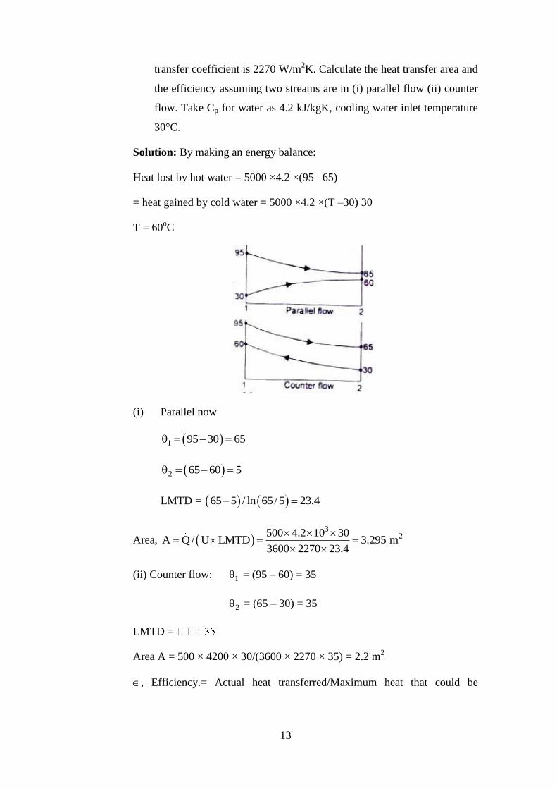
transfer coefficient is 2270 W/m2K. Calculate the heat transfer area and
the efficiency assuming two streams are in (i) parallel flow (ii) counter
flow. Take Cp for water as 4.2 kJ/kgK, cooling water inlet temperature
30°C.
Solution: By making an energy balance:
Heat lost by hot water = 5000 ×4.2 ×(95 –65)
= heat gained by cold water = 5000 ×4.2 ×(T –30) 30
T = 60oC
(i) Parallel now
1 95 30 65
2 65 60 5
LMTD = 65 5 / ln 65/5 23.4
Area, 3
2500 4.2 10 30A Q / U LMTD 3.295 m
3600 2270 23.4
(ii) Counter flow: 1 = (95 – 60) = 35
2 = (65 – 30) = 35
LMTD =
Area A = 500 × 4200 × 30/(3600 × 2270 × 35) = 2.2 m2
, Efficiency.= Actual heat transferred/Maximum heat that could be
14
transferred. Therefore, for parallel flow, = (95 – 65)/(95 – 60) = 0.857
For counter flow, = (95 - 65)/(95 – 30) = 0.461.
Counter now
Example 3.5 The flow rates of hot and cold water streams running through a double
pipe heat exchanger (inside and outside diameter of the tube 80 mm
and 100 mm) are 2 kg/s and 4 kg/so The hot fluid enters at 75°C and
comes out at 45oC. The cold fluid enters at 20°C. If the convective
heat transfer at the inside and outside surface of the tube is 150 and
180 W /m2K, thermal conductivity of the tube material 40 W/mK,
calculate the area of the heat exchanger assuming counter flow.
Solution: Let T is the temperature of the cold water at outlet.
By making an energy balance, h h h1 h2 c c c2 c1Q m c T T m c T T
since oh cc c , 4.2 kJ / kgK; 2 75 45 4 T 20 ; T 35 C
and Q 252 kW
for counter flow: 1 275 35 40; 45 20 25
LMTD = (40 – 25) / ln (40/25) = 31.91
overall heat transfer coefficient based in the inside surface of tube
i i o i o i o1/ U 1/ h r / k ln r / r r r 1/ h
1/150 0.04/ 40 ln 50/ 40 50/ 40 1/180 0.0138
and U = 72.28
area 3 2A Q/ U LMTD 252 10 / 72.28 31.91 109.26 m
Example 3.6 Water flows through a copper tube (k = 350 W/mK, inner and outer
diameter 2.0 cm and 2.5 cm respectively) of a double pipe heat
exchanger. Oil flows through the annulus between this pipe and
steel pipe. The convective heat transfer coefficient on the inside and
outside of the copper tube are 5000 and 1500 W /m2K. The fouling
factors on the water and oil sides are 0.0022 and 0.00092 K1W.
15
Calculate the overall heat transfer coefficient with and without the
fouling factor.
Solution: The scales formed on the inside and outside surface of the copper
tube introduces two additional resistances in the heat flow path. Resistance due to
inside convective heat transfer coefficient
i i i1/ h A 1/5000 A
Resistance due to scale formation on the inside = 1/hsAi = 0.0022
Resistance due to conduction through the tube wall = o iln r / r / 2 Lk
4ln 2.5/ 2.0 / 2 L 350 1.014 10 / L
Resistance due to convective heat transfer on the outside
o o o1/ h A 1/1500A
Resistance due to scale formation on the outside = s o1/ h A 0.00092
Since, i 1 i iQ T R U A T T / 1/ U A ; we have
(a) With fouling factor:-
Overall heat transfer coefficient based on the inside pipe surface
4 4iU 1/ 1/ 5000 0.02 0.0022 0.00092 0.02 1.014 10 8.33 10
= 809.47 W/m2K per metre length of pipe
(b) Without fouling factor
4 4iU 1/ 1/ 5000 0.02 1.014 10 8.33 10
= 962.12 W/m2K per m of pipe length.
The heat transfer rate will reduce by (962.12 – 809.47)1962.12 = 15.9
percent when fouling factor is considered.
Example 3.7 In a surface condenser, dry and saturated steam at 50oC enters at the
rate of 1 kg/so The circulating water enters the tube, (25 nun inside
diameter, 28 mm outside diameter, k = 300 W/mK) at a velocity of
16
2 m/s. If the convective heat transfer coefficient on the outside
surface of the tube is 5500 W/m2K, the inlet and outlet temperatures
of water are 25oC and 35
oC respectively, calculate the required
surface area.
Solution: For calculating the convective heat transfer coefficient on the
inside surface of the tube, we calculate the Reynolds number on the basis of
properties of water at the mean temperature of 30oC. The properties are:
= 0.001 Pa-3, k = 0.6 W/mK, hfg at 50
oC = 2375 kJ/kg
3 × 2 × 0.025/0.001 = 50,000, a turbulent flow. Pr = 7.0.
The heat transfer coefficient at the inside surface can be calculated by:
Nu = 0.023 Re0.8
8 Pr0.3
= 0.023 (50000)0.8
(7)0.3
= 236.828
and hi = 236.828 × 0.6/0.025 = 5684 W/m2K.
The overall heat transfer coefficient based on the outer diameter,
U = 1/(0.028/(0.025 × 5684) + 1/5500 + 0.014 ln(28/25)/300)
= 2603.14 W/m2K
a. = (50 - 25) = 25 b = (50 - 35) = 15;
-15)/ln(25/15) = 19.576.
Assuming one shell pass and one tube pass, Q = UA (LMTD)
or A = 2375 × 103/(2603.14 x 19.576) = 46.6 m
2
Mass of Circulating water = Q/(cp
also, mw × area × V × n, where n is the number of tubes.
Hence more than one pass should be used.
Example 3.8 A heat exchanger is used to heat water from 20°C to 50°C when thin
walled water tubes (inner diameter 25 mm, length IS m) are laid
17
beneath a hot spring water pond, temperature 75°C. Water flows
through the tubes with a velocity of 1 m/s. Estimate the required
overall heat transfer coefficient and the convective heat transfer
coefficient at the outer surface of the tube.
Solution: Water flow rate, m = 3
2
= 0.49 kg/so
Heat transferred to water, Q = m
Since the temperature of the water in the hot spring is constant,
1 275 20 55; 75 50 25 ;
LMTD = (55 – 25) / ln(55/25) = 38
Overall heat transfer coefficient, U = Q/ (A × LMTD)
2K.
The properties of water at the mean temperature (20 + 50)/2 = 35°C are:
0.001 Pa s, k 0.6 W/ mk and Pr = 7.0
Reynolds number, Re Vd / 1000 1.0 0.25/ 0.001 25000 , turbulent
flow.
Nu = 0.023 (Re)0.8
(Pr)0.33
= 0.023 (25000)0.8
× (7)0.33
= 144.2
and hi = 144.2 × k/d = 144.2 × 0.6/0.025 = 3460.8 W/m2K
Neglecting the resistance of the thin tube wall,
1/U = 1/hi + 1/ho; o1/ h 1/1378.94 1/3460.8
or, 2oh 2292.3 W / m K
Example 3.9 A hot fluid at 200°C enters a heat exchanger at a mass rate of
10000 kg/h. Its specific heat is 2000 J/kg K. It is to be cooled by
another fluid entering at 25°C with a mass flow rate 2500 k g/h and
specific heat 400 J/kgK. The overall heat transfer coefficient based
on outside area of 20 m2 is 250 W/m2K. Find the exit temperature
of the hot fluid when the fluids are in parallel flow.
18
Solution: From Eq(10.3a), h cU dA 1/ C 1/ C d T / T
Upon integration,
2h c 1UA 1/ C 1/ C ln T |
0 0 i ih c h cln T T / T T
The values are: U = 250 W/m2K
A = 20 m2
l/Ch = 3600/(10000 × 2000) = 1.8 × 10⁻⁴
1/Cc = 3600/(2500 × 400) = 3.6 × 10⁻³
–UA(1/Ch + l/Cc) = –250 × 20 (1.8 × 10⁻⁴
+ 3.6 × 10⁻³
) = -18.9
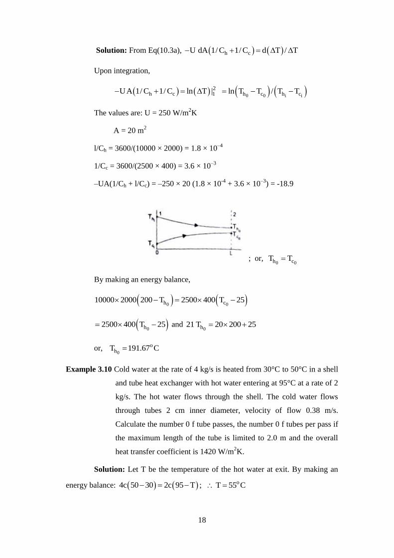
; or, 0 0h cT T
By making an energy balance,
0 0h c10000 2000 200 T 2500 400 T 25
0h2500 400 T 25 and
0h21 T 20 200 25
or, 0
ohT 191.67 C
Example 3.10 Cold water at the rate of 4 kg/s is heated from 30°C to 50°C in a shell
and tube heat exchanger with hot water entering at 95°C at a rate of 2
kg/s. The hot water flows through the shell. The cold water flows
through tubes 2 cm inner diameter, velocity of flow 0.38 m/s.
Calculate the number 0 f tube passes, the number 0 f tubes per pass if
the maximum length of the tube is limited to 2.0 m and the overall
heat transfer coefficient is 1420 W/m2K.
Solution: Let T be the temperature of the hot water at exit. By making an
energy balance: 4c 50 30 2c 95 T ; oT 55 C
19
For a counter-flow arrangement:
aT 95 50 45 , bT 55 30 25 ,
LMTD 45 25 / ln 45/ 25 34; Q mC T 4 4.182 20 334.56 kW
Since the cold water is flowing through the tubes, the number of tubes, n is
given by
m n Area × velocity; the cross-sectional area 3.142 × 10⁻²
m2
4 = n × 1000 × 3.142 × 10–4
Assuming one shell and two tube pass, we use Fig. 10.9(a).
P 50 30 / 95 30 0.3 ; Z 95 55 / 50 30 2.0
Therefore, the correction factor, F = 0.88
Q = UAF LMTD; 34560 = 1420 × A × 0.88 × 34; or A = 7.875 m2.
L = 1.843 m
Thus we will have 1 shell pass, 2 tube; 34 tubes of 1.843 m in length.
Example 3.11 A double pipe heat exchanger is used to cool compressed air (pressure
A bar, volume flow rate 5 mJ/mm at I bar and 15°C) from 160°C to
35°C. Air flows with a velocity of 5 m/s through thin walled tubes, 2 cm
inner diameter. Cooling water flows through the annulus and its
temperature rises from 25°C to 40°C. The convective heat transfer
coefficient at the inside and outside tube surfaces are 125 W/m2K and
2000 W/m2K respectively. Calculate (i) mass of water flowing through
the exchanger, and (ii) number of tubes and length of each tube.
Solution: Air is cooled from 1600C to 35°C while water is heated from
25°C to 400C and therefore this must be a counter flow arrangement.
Temperature difference at section 1 : i 0h cT T 160 40 120
Temperature difference at section 2 : 0 ih cT T 35 25 10
20
LMTD = (120 –10)/ln 120/10) = 44.27
Mass of air flowing, m =
510 / 287 288 5/ 60 0.1 kg / s
Heat given out by air = Heat taken in by water,
w0.1 1.005 160 35 m 4.182 40 25 ; Or wm 0.20 kg / s
air flowing through the tube is (160 + 35)/2 = 97.5 oC = 370.5K
5/(287 × 370.5) = 3.76 kg/m
3. If n is the number of
tubes, from the conservation of mass, m AV 2 × 5 × n
17 tubes; Q = UA (LMTD)
Q = UA(LMTD); 0.1 × 1005 × 125 = 117.65 × 3.142 × 0.02 × L × 17 ×
44.27 and L = 2.26 m.
Example 3.12 A refrigerant (mass rate of flow 0.5 kg/s, S = 907 J/kgK k = 0.07
W/mK–4
Pa-s) at –20°C flows through the annulus
(inside diameter 3 c m) of a double pipe counter flow heat exchanger
used to cool water (mass flow rate 0.05 kg/so k = 0.68 W/mK,
–4 Pa-s) at 98°C flowing through a thin walled copper
tube of 2 cm inner diameter. If the length of the tube is 3m, estimate
(i) the overall heat transfer coefficient, and (ii) the temperature of the
fluid streams at exit.
Solution: Mass rate of flow, m AV = 2/ 4 D V ;
VD 4m/ D and, Reynolds number, Re VD/ 4m/ D
Water is flowing through the tube of diameter 2 cm,
4 4Re 4 0.05/ 3.142 0.02 2.83 10 1.12 10 , turbulent flow.
0.80.33 0.330.8 4Nu 0.023 Re Pr 0.023 1.12 10 1.8
21
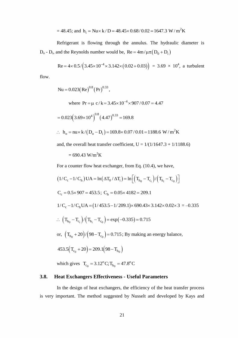
= 48.45; and 2ih Nu k / D 48.45 0.68/ 0.02 1647.3 W / m K
Refrigerant is flowing through the annulus. The hydraulic diameter is
Do - Di, and the Reynolds number would be, 0 iRe 4m/ D D
4Re 4 0.5/ 3.45 10 3.142 0.02 0.03 = 3.69 × 10⁴, a turbulent
flow.
0.8 0.33
Nu 0.023 Re Pr ,
where 4Pr c / k 3.45 10 907 / 0.07 4.47
0.8 0.3340.023 3.69 10 4.47 169.8
2o o ih nu k / D D 169.8 0.07 / 0.01 1188.6 W / m K
and, the overall heat transfer coefficient, U = 1/(1/1647.3 + 1/1188.6)
= 690.43 W/m2K
For a counter flow heat exchanger, from Eq. (10.4), we have,
0 i i 0c h 0 i h c h c1/ C 1/ C UA ln T / T ln T T / T T
cC 0.5 907 453.5 ; hC 0.05 4182 209.1
c h1/ C 1/ C UA 1/ 453.5 1/ 209.1 690.43 3.142 0.02 3 = –0.335
0 i i 0h c h cT T / T T exp 0.335 0.715
or, 0 0h cT 20 / 98 T 0.715 ; By making an energy balance,
0 0c h453.5 T 20 209.1 98 T
which gives 0 0
o oc hT 3.12 C;T 47.8 C
3.8. Heat Exchangers Effectiveness - Useful Parameters
In the design of heat exchangers, the efficiency of the heat transfer process
is very important. The method suggested by Nusselt and developed by Kays and
22
London is now being extensively used. The effectiveness of a heat exchanger is
defined as the ratio of the actual heat transferred to the maximum possible heat
transfer.
Let hm and cm be the mass flow rates of the hot and cold fluids, ch and cc
be the respective specific heat capacities and the terminal temperatures be Th and T h
for the hot fluid at inlet and outlet, ihT and
0hT for the cold fluid at inlet and outlet.
By making an energy balance and assuming that there is no loss of energy to the
surroundings, we write
i 0 i 0h h h h h h cQ m c T T C T T , and
0 i 0 ic c c c c c cm c T T C T T (3.13)
From Eq. (10.13), it can be seen that the fluid with smaller thermal capacity,
C, has the greater temperature change. Further, the maximum temperature change of
any fluid would be i ih cT T and this Ideal temperature change can be obtained
with the fluid which has the minimum heat capacity rate. Thus,
Effectiveness, i imin h cQ/ C T T (3.14)
Or, the effectiveness compares the actual heat transfer rate to the maximum
heat transfer rate whose only limit is the second law of thermodynamics. An useful
parameter which also measures the efficiency of the heat exchanger is the 'Number of
Transfer Units', NTU, defined as
NTU = Temperature change of one fluid/LMTD.
Thus, for the hot fluid: NTU = i 0h hT T / LMTD , and
for the cold fluid: 0 ic cNTU T T / LMTD
Since i 0h h hQ UA LMTD C T T
0 ic c cC T T
we have h hNTU UA / C and c cNTU UA / C
The heat exchanger would be more effective when the NTU is greater, and
23
therefore,
NTU = AU/Cmin (3.15)
An another useful parameter in the design of heat exchangers is the ratio the
minimum to the maximum thermal capacity, i.e., R = Cmin/Cmax,
where R may vary between I (when both fluids have the same thermal
capacity) and 0 (one of the fluids has infinite thermal capacity, e.g., a condensing
vapour or a boiling liquid).