Troubleshooting Gas-lift Wells
Using Dual Shot Acoustic Technique
• Shea Province - Apache Corp
• Carrie Anne Taylor
• Lynn Rowlan
2018 Artificial Lift Strategies for
Unconventional Wells Workshop Cox Convention Center, Oklahoma City, OK
February 4 – 7, 2018
2018 Artificial Lift Strategies for Unconventional Wells Workshop
Oklahoma City, OK

2
Introduction
• In Unconventional Reservoirs, Many traditional
Sucker Rod Lift operators have done a significant
shift toward Gas-Lift as the primary lift method
• Simple method needed to find/identify leaks and/or
pressure communication through the tubing
• Wellbore problems or equipment malfunctions from
holes or defective checks or valves is found by
identifying pressure communication through tubing
• Acoustic fluid level provides beneficial information
throughout the life of a gas-lift well
• Using a known valve depth is an accurate method to
determine the depth to the fluid level
Efficient operation of artificial lifted wells normally
requires the fluids moving to the surface in the
tubing to be isolated from the casing annulus.
2018 Artificial Lift Strategies for Unconventional Wells Workshop
Oklahoma City, OK Feb. 4 - 7, 2018

Fire Shot Only
Listen and Record
1
2
3
4
5
6
7
8
9
10
11
1. Displace liquid out of Tubing down to the operating valve.
2. Fire Shot using Remote Fire Gun on Tubing. Disconnect Tubing microphone cable after Shot is fired.
3. Listen and Record Shot using Compact Gas Gun on Casing.
4. Watch for Kick identifying communication between Tubing and Casing.
5. Using the average of the Tubing and Casing Acoustic Velocities, calculate the Depth to the Kick.
6. Using the Wellbore Schematic or Overlay, identify the Problem Valve.
Dual Shot Method X

Overlay Casing Setup Shot onto Dual Shot to Verify
1 2 3 4 5 6 7 8 9 10 11

The Dual Shot Method
5 2018 Artificial Lift Strategies for Unconventional Wells Workshop
Oklahoma City, OK Feb. 4 - 7, 2018

Dual Shot Method Look for Communication between Tubing and Casing on a Gas-lift Well. • Shoot down Tubing and
simultaneously Listen on Casing.
• Fire the Tubing Gas Gun to send a pressure wave down Tubing.
• Unplug the Tubing microphone cable from T after shot is fired, and leave the Casing microphone cable plugged into the Well Analyzer.
• Acoustic Signal is created in Tubing. Holes, malfunctioning check valves, and malfunctioning gas-lift valves pass pressure wave into casing.
• For calculating Depth on Listen gun, use an average of the Tubing and Casing Acoustic Velocities from just prior Tubing and Casing shots.
Tubing
Remote Fire
Gas Gun
Listen with
Gas Gun on
Casing

Use Low Pass Filter to See Casing Mandrel Echoes
1 2 3 4 5 6 7 8 9 Orifice
Wellbore Overlay
Just Prior Casing Shot

Use Valve #9 Depth for 1177 ft/sec Acoustic Velocity
1 2 3 4 5 6 7 8 9 Orifice
Use Gas-lift Valve #9 6791 foot Depth 11.497 RTTT to Calculate Average Casing Acoustic Velocity 1177 ft/s and Determine the fluid level is near/at the orifice.
Liquid Level
Just Prior Casing Shot

EOT Echo Determines 1255 ft/s Acoustic Velocity
RTTT 12.218 Sec @ End of Tubing Depth: 7688
Use EOT 7688 foot Depth 12.218 sec RTTT to Calculate Average Tubing Acoustic Velocity 1255 ft/s.
Just Prior Tubing Shot

Connect Both Guns to Analyzer for Shot Fire
Shoot Tubing
Remote Fire
Gas Gun
Listen with
Gas Gun on
Casing
Look for Communication between Tubing and Casing on a Gas-lift Well.
• Shoot down Tubing and Simultaneously Listen on Casing

After Shot Fire Listen Only on Casing Gun
As soon as Tubing Shot is fired Unplug the Tubing microphone cable from T and leave the casing microphone cable plugged into the Well Analyzer.
Fire Remote
Fire Gas Gun
on Tubing
Listen with
Gas Gun on
Casing
Dual Shot Results
• Example 1
12 2018 Artificial Lift Strategies for Unconventional Wells Workshop
Oklahoma City, OK Feb. 4 - 7, 2018

Tubing Shot
Casing Shot
Dual Shot
On Casing Gun see Bad Check Valve and EOT Echo

Tubing Shot
Casing Shot
Dual Shot
EOT Echo Determines 1255 ft/s Acoustic Velocity
Use Valve #9 Depth for 1177 ft/s Acoustic Velocity
Acoustic Velocity = 1216 ft/s (1255+1177)/2

Dual Shot Results
• Example 2
15 2018 Artificial Lift Strategies for Unconventional Wells Workshop
Oklahoma City, OK Feb. 4 - 7, 2018

Tubing Shot
Use notes to identify
Dual Shot Markers
Casing Shot

17
Echoes from Both Tubing and
Casing are seen in Dual Shot.
Casing
Liquid
Level
EOT Communication near 4th Valve,
could be bad valve or HIT
Liquid Level
through
Tubing
Apply Low Pass Filter
and Zoom In
2018 Artificial Lift Strategies for Unconventional Wells Workshop
Oklahoma City, OK Feb. 4 - 7, 2018

Dual Shot Method Using
Plunger Lift Application
18 2018 Artificial Lift Strategies for Unconventional Wells Workshop
Oklahoma City, OK Feb. 4 - 7, 2018

Dual Shot - Wireless Look for Communication between Tubing and Casing on a Gas-lift Well.
• Using TAM Plunger Lift Application Simultaneously Acquire High Speed Acoustic and Pressure Data.
• Press Fire Shot button on Tubing Gun while Listening for Pass Through Echo on Casing Gun.
• Acoustic Signal is created in Tubing. Holes, malfunctioning check valves, and malfunctioning gas-lift valves pass pressure wave into casing.
• For calculating Depth on Listen gun, use an average of the Tubing and Casing Acoustic Velocities from just prior Tubing and Casing shots.
Tubing
Wireless
Remote Fire
Gas Gun
Listen with
Wireless 5K
Gas Gun on
Casing

1000 hz
Using TAM Plunger Lift Application Simultaneously
Acquire High Speed Acoustic and Pressure Data

Press fire shot button on Tubing Gun while
Listening for Pass Through Echo on Casing
Press “Fire”
button when ready
to shoot and make
sure the chamber
pressure is
greater than the
well pressure.
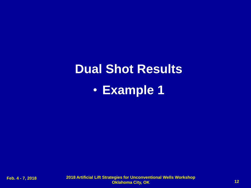
Acoustic Signal is created in Tubing. If holes, leaky check valves, leaky gas-lift valves are present, then Tubing Pressure Wave enters Casing.
End of Tubing Echo Depth: 7688
Liquid Level Echo Depth: 7950

Acoustic Signal Recorded in Casing shows holes, leaky check valves & leaky gas-lift valves when tubing pressure wave can pass into casing
On Casing Gun see Down kick from Bad Check and Up kick from EOT Echo
24
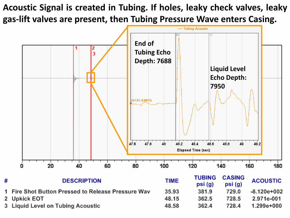
Conclusion
• Dual Shot Method is Used to find holes in Tubing, plus
malfunctioning check valves and/or gas-lift valves
• Passing pressure wave from one pipe into adjacent pipe
is the method to identify depth of leak
• Beneficial information is obtained throughout the life of a
gas-lift well through acoustic surveys
• Knowing the Acoustic Velocity profile of a well provides
critical information for verifying gas composition and
fluid level accuracy.
• Identifying reflection kicks across valves and mandrels
result in more accurate depth analysis.
• New technique aids in troubleshooting problems.
2018 Artificial Lift Strategies for Unconventional Wells Workshop
Oklahoma City, OK Feb. 4 - 7, 2018

Copyright
Rights to this presentation are owned by the company(ies) and/or author(s) listed on the title page. By submitting this presentation to the Artificial Lift Strategies for Unconventional Wells Workshop, they grant to the Workshop, the Artificial Lift Research and Development Council (ALRDC), and the Southwestern Petroleum Short Course (SWPSC), rights to:
Display the presentation at the Workshop.
Place it on the www.alrdc.com web site, with access to the site to be as directed by the Workshop Steering Committee.
Place it on a CD for distribution and/or sale as directed by the Workshop Steering Committee.
Other use of this presentation is prohibited without the expressed written permission of the author(s). The owner company(ies) and/or author(s) may publish this material in other journals or magazines if they refer to the Artificial Lift Strategies for Unconventional Wells Workshop where it was first presented.
25 2018 Artificial Lift Strategies for Unconventional Wells Workshop
Oklahoma City, OK Feb. 4 - 7, 2018

Disclaimer
26 2018 Artificial Lift Strategies for Unconventional Wells Workshop
Oklahoma City, OK Feb. 4 - 7, 2018
The following disclaimer shall be included as the last page of a Technical Presentation or Continuing Education Course. A similar disclaimer is included on the front page of the Artificial Lift Strategies for Unconventional Wells Web Site.
The Artificial Lift Research and Development Council and its officers and trustees, and the Artificial Lift Strategies for Unconventional Wells Steering Committee members, and their supporting organizations and companies (here-in-after referred to as the Sponsoring Organizations), and the author(s) of this Technical Presentation or Continuing Education Training Course and their company(ies), provide this presentation and/or training material at the Artificial Lift Strategies for Unconventional Wells Workshop "as is" without any warranty of any kind, express or implied, as to the accuracy of the information or the products or services referred to by any presenter (in so far as such warranties may be excluded under any relevant law) and these members and their companies will not be liable for unlawful actions and any losses or damage that may result from use of any presentation as a consequence of any inaccuracies in, or any omission from, the information which therein may be contained.
The views, opinions, and conclusions expressed in these presentations and/or training materials are those of the author and not necessarily those of the Sponsoring Organizations. The author is solely responsible for the content of the materials.
The Sponsoring Organizations cannot and do not warrant the accuracy of these documents beyond the source documents, although we do make every attempt to work from authoritative sources. The Sponsoring Organizations provide these presentations and/or training materials as a service. The Sponsoring Organizations make no representations or warranties, express or implied, with respect to the presentations and/or training materials, or any part thereof, including any warrantees of title, non-infringement of copyright or patent rights of others, merchantability, or fitness or suitability for any purpose.