E6581540
TOSVERT VF-PS1 series
Metasys® N2 option unit Function Manual
MTS001Z
NOTICE
1. Make sure that this instruction manual is delivered to the end user of Metasys® N2
option unit. 2. Read this manual before installing or operating the Metasys® N2 option unit. Keep
it in a safe place for reference. 3. All information contained in this manual are subject to change without notice.
Please confirm the latest information on our web site “www.inverter.co.jp”.

E6581540
- 1 -
Table of Contents 1. INTRODUCTION.........................................................................................................................................2 2. NAMES AND FUNCTIONS OF MAIN PARTS...........................................................................................3
2.1. Outline view..........................................................................................................................................3 2.2. Metasys® N2 Connector ......................................................................................................................3 2.3. LED indicator........................................................................................................................................4 2.4. Setting a station address......................................................................................................................5
3. PARAMETERS ...........................................................................................................................................9 3.1. Communication parameters.................................................................................................................9 3.2. f832: Communication Loss Action Time Setting ..........................................................................10 3.3. f851: Communication Loss Action Setting ...................................................................................10 3.4. f852: Preset speed operation selection........................................................................................10
4. FUNCTIONAL PROFILE ..........................................................................................................................11 4.1. Synch Time Command.......................................................................................................................12 4.2. Status Update Request ......................................................................................................................12 4.3. Analog Input Object............................................................................................................................13
4.3.1. Analog Input Attribute .................................................................................................................14 4.3.2. Analog Input COS Works............................................................................................................15
4.4. Binary Input Object.............................................................................................................................16 4.4.1. Binary Input Attribute ..................................................................................................................17
4.5. Binary Input COS Works ....................................................................................................................17 4.6. Analog Output Object.........................................................................................................................18
4.6.1. Analog Output Attribute...............................................................................................................19 4.6.2. Analog Output COS Works.........................................................................................................19
4.7. Binary Output Object..........................................................................................................................20 4.7.1. Binary Output Attribute................................................................................................................21 4.7.2. Binary Output COS Works..........................................................................................................21
4.8. Error Message Format .......................................................................................................................22 4.9. VF-PS1 Parameter access ................................................................................................................23
5. VF-PS1 TRIP CODE .................................................................................................................................24 6. SPECIFICATIONS ....................................................................................................................................26
- 1/26 -

E6581540
- 2 -
1. Introduction Thank you for purchasing the Metasys® N2 option unit (MTS001Z) for VF-PS1 series inverter. Before using Metasys® N2 option unit, carefully read this function manual in order to completely and correctly utilize its excellent performance. After reading this function manual, please keep it handy for future reference. For details of its general handling, see an instruction manual attached with the option unit.
・TOSVERT VF-PS1 Instruction Manual ...................................E6581386 ・TOSVERT VF-PS1 RS485 Communication Manual...............E6581413 ・MTS001Z Instruction Manual ..................................................E6581539
* Metasys® N2 is a registered trademark of Johnson Controls Inc.

E6581540
- 3 -
2. Names and functions of main parts
2.1. Outline view
2.2. Metasys® N2 Connector
Terminal symbol Function Electrical specifications Internal circuits
B Communication signal (+) A Communication signal (-)
GND Signal common
SCR
Metasys® N2 communication signal EIA-485
Shield terminal.
B
A
GND
SCR
47k
47k
4.7k
4.7k
120SW4
TERM
Don’t use these connector or switches
Connector to the inverter
Metasys® N2 Connector(refer to 2.2) (Terminal connector : MSTB 2,5/4-STF-5.08) : PHOENIX CONTACT
Termination Resistor SW
Panel mounting tabs
Earth Plate
Metasys® N2 LED indicator
(refer to 2.3)
Station address switch
(refer to 2.4)

E6581540
- 4 -
2.3. LED indicator The option has two LEDs. Those function are below table.
Table 1 LED Behavior State LEDs Comment
A COM LED: OFF ERR LED: Flashing 5 times in 1 second
Metasys® N2 failure.
B COM LED: OFF ERR LED: 3 times in 2 sec, Off for 1 sec
Communication loss detected. Confirm the network condition and connection of the cable.
C COM LED: ON ERR LED: OFF 0.5 sec, ON 0.5 sec
Invalid configuration detected. Note: When inverter occurred in e-23 or
e-24, the LED becomes this state.
D COM LED: Flashing ERR LED: -
Valid message received for this node
E COM LED: - ERR LED: Flashing
Invalid message received (any node)
F COM LED: OFF ERR LED: OFF
No communication Confirm the network condition and connection of the cable.
COM (Green)
ERR (Red)
2s
OFF
1s
B D
OFF
E
OFF
1s
ON
C
1s
OFF
A F
OFF
OFF

E6581540
- 5 -
2.4. Setting a station address
The DIP switch on the circuit board of the option is used to set a station address. Each DIP switch is ON when it is flipped to the lower position. By default, it is factory-configured to 1. The station address must be unique and not match any other device on the network.
SW ID 1 2 3 4 5 6 7 8 SW
ID 1 2 3 4 5 6 7 8
0 * OFF OFF OFF OFF OFF OFF OFF OFF 32 OFF OFF ON OFF OFF OFF OFF OFF
1 OFF OFF OFF OFF OFF OFF OFF ON 33 OFF OFF ON OFF OFF OFF OFF ON
2 OFF OFF OFF OFF OFF OFF ON OFF 34 OFF OFF ON OFF OFF OFF ON OFF
3 OFF OFF OFF OFF OFF OFF ON ON 35 OFF OFF ON OFF OFF OFF ON ON
4 OFF OFF OFF OFF OFF ON OFF OFF 36 OFF OFF ON OFF OFF ON OFF OFF
5 OFF OFF OFF OFF OFF ON OFF ON 37 OFF OFF ON OFF OFF ON OFF ON
6 OFF OFF OFF OFF OFF ON ON OFF 38 OFF OFF ON OFF OFF ON ON OFF
7 OFF OFF OFF OFF OFF ON ON ON 39 OFF OFF ON OFF OFF ON ON ON
8 OFF OFF OFF OFF ON OFF OFF OFF 40 OFF OFF ON OFF ON OFF OFF OFF
9 OFF OFF OFF OFF ON OFF OFF ON 41 OFF OFF ON OFF ON OFF OFF ON
10 OFF OFF OFF OFF ON OFF ON OFF 42 OFF OFF ON OFF ON OFF ON OFF
11 OFF OFF OFF OFF ON OFF ON ON 43 OFF OFF ON OFF ON OFF ON ON
12 OFF OFF OFF OFF ON ON OFF OFF 44 OFF OFF ON OFF ON ON OFF OFF
13 OFF OFF OFF OFF ON ON OFF ON 45 OFF OFF ON OFF ON ON OFF ON
14 OFF OFF OFF OFF ON ON ON OFF 46 OFF OFF ON OFF ON ON ON OFF
15 OFF OFF OFF OFF ON ON ON ON 47 OFF OFF ON OFF ON ON ON ON
16 OFF OFF OFF ON OFF OFF OFF OFF 48 OFF OFF ON ON OFF OFF OFF OFF
17 OFF OFF OFF ON OFF OFF OFF ON 49 OFF OFF ON ON OFF OFF OFF ON
18 OFF OFF OFF ON OFF OFF ON OFF 50 OFF OFF ON ON OFF OFF ON OFF
19 OFF OFF OFF ON OFF OFF ON ON 51 OFF OFF ON ON OFF OFF ON ON
20 OFF OFF OFF ON OFF ON OFF OFF 52 OFF OFF ON ON OFF ON OFF OFF
21 OFF OFF OFF ON OFF ON OFF ON 53 OFF OFF ON ON OFF ON OFF ON
22 OFF OFF OFF ON OFF ON ON OFF 54 OFF OFF ON ON OFF ON ON OFF
23 OFF OFF OFF ON OFF ON ON ON 55 OFF OFF ON ON OFF ON ON ON
24 OFF OFF OFF ON ON OFF OFF OFF 56 OFF OFF ON ON ON OFF OFF OFF
25 OFF OFF OFF ON ON OFF OFF ON 57 OFF OFF ON ON ON OFF OFF ON
26 OFF OFF OFF ON ON OFF ON OFF 58 OFF OFF ON ON ON OFF ON OFF
27 OFF OFF OFF ON ON OFF ON ON 59 OFF OFF ON ON ON OFF ON ON
28 OFF OFF OFF ON ON ON OFF OFF 60 OFF OFF ON ON ON ON OFF OFF
29 OFF OFF OFF ON ON ON OFF ON 61 OFF OFF ON ON ON ON OFF ON
30 OFF OFF OFF ON ON ON ON OFF 62 OFF OFF ON ON ON ON ON OFF
31 OFF OFF OFF ON ON ON ON ON 63 OFF OFF ON ON ON ON ON ON* “0” must not be set as station address.
1 2 3 4 5 6 7 8DIP ON

E6581540
- 6 -
SW
ID 1 2 3 4 5 6 7 8 SWID 1 2 3 4 5 6 7 8
64 OFF ON OFF OFF OFF OFF OFF OFF 96 OFF ON ON OFF OFF OFF OFF OFF
65 OFF ON OFF OFF OFF OFF OFF ON 97 OFF ON ON OFF OFF OFF OFF ON
66 OFF ON OFF OFF OFF OFF ON OFF 98 OFF ON ON OFF OFF OFF ON OFF
67 OFF ON OFF OFF OFF OFF ON ON 99 OFF ON ON OFF OFF OFF ON ON
68 OFF ON OFF OFF OFF ON OFF OFF 100 OFF ON ON OFF OFF ON OFF OFF
69 OFF ON OFF OFF OFF ON OFF ON 101 OFF ON ON OFF OFF ON OFF ON
70 OFF ON OFF OFF OFF ON ON OFF 102 OFF ON ON OFF OFF ON ON OFF
71 OFF ON OFF OFF OFF ON ON ON 103 OFF ON ON OFF OFF ON ON ON
72 OFF ON OFF OFF ON OFF OFF OFF 104 OFF ON ON OFF ON OFF OFF OFF
73 OFF ON OFF OFF ON OFF OFF ON 105 OFF ON ON OFF ON OFF OFF ON
74 OFF ON OFF OFF ON OFF ON OFF 106 OFF ON ON OFF ON OFF ON OFF
75 OFF ON OFF OFF ON OFF ON ON 107 OFF ON ON OFF ON OFF ON ON
76 OFF ON OFF OFF ON ON OFF OFF 108 OFF ON ON OFF ON ON OFF OFF
77 OFF ON OFF OFF ON ON OFF ON 109 OFF ON ON OFF ON ON OFF ON
78 OFF ON OFF OFF ON ON ON OFF 110 OFF ON ON OFF ON ON ON OFF
79 OFF ON OFF OFF ON ON ON ON 111 OFF ON ON OFF ON ON ON ON
80 OFF ON OFF ON OFF OFF OFF OFF 112 OFF ON ON ON OFF OFF OFF OFF
81 OFF ON OFF ON OFF OFF OFF ON 113 OFF ON ON ON OFF OFF OFF ON
82 OFF ON OFF ON OFF OFF ON OFF 114 OFF ON ON ON OFF OFF ON OFF
83 OFF ON OFF ON OFF OFF ON ON 115 OFF ON ON ON OFF OFF ON ON
84 OFF ON OFF ON OFF ON OFF OFF 116 OFF ON ON ON OFF ON OFF OFF
85 OFF ON OFF ON OFF ON OFF ON 117 OFF ON ON ON OFF ON OFF ON
86 OFF ON OFF ON OFF ON ON OFF 118 OFF ON ON ON OFF ON ON OFF
87 OFF ON OFF ON OFF ON ON ON 119 OFF ON ON ON OFF ON ON ON
88 OFF ON OFF ON ON OFF OFF OFF 120 OFF ON ON ON ON OFF OFF OFF
89 OFF ON OFF ON ON OFF OFF ON 121 OFF ON ON ON ON OFF OFF ON
90 OFF ON OFF ON ON OFF ON OFF 122 OFF ON ON ON ON OFF ON OFF
91 OFF ON OFF ON ON OFF ON ON 123 OFF ON ON ON ON OFF ON ON
92 OFF ON OFF ON ON ON OFF OFF 124 OFF ON ON ON ON ON OFF OFF
93 OFF ON OFF ON ON ON OFF ON 125 OFF ON ON ON ON ON OFF ON
94 OFF ON OFF ON ON ON ON OFF 126 OFF ON ON ON ON ON ON OFF
95 OFF ON OFF ON ON ON ON ON 127 OFF ON ON ON ON ON ON ON

E6581540
- 7 -
SW
ID 1 2 3 4 5 6 7 8 SWID 1 2 3 4 5 6 7 8
128 ON OFF OFF OFF OFF OFF OFF OFF 160 ON OFF ON OFF OFF OFF OFF OFF
129 ON OFF OFF OFF OFF OFF OFF ON 161 ON OFF ON OFF OFF OFF OFF ON
130 ON OFF OFF OFF OFF OFF ON OFF 162 ON OFF ON OFF OFF OFF ON OFF
131 ON OFF OFF OFF OFF OFF ON ON 163 ON OFF ON OFF OFF OFF ON ON
132 ON OFF OFF OFF OFF ON OFF OFF 164 ON OFF ON OFF OFF ON OFF OFF
133 ON OFF OFF OFF OFF ON OFF ON 165 ON OFF ON OFF OFF ON OFF ON
134 ON OFF OFF OFF OFF ON ON OFF 166 ON OFF ON OFF OFF ON ON OFF
135 ON OFF OFF OFF OFF ON ON ON 167 ON OFF ON OFF OFF ON ON ON
136 ON OFF OFF OFF ON OFF OFF OFF 168 ON OFF ON OFF ON OFF OFF OFF
137 ON OFF OFF OFF ON OFF OFF ON 169 ON OFF ON OFF ON OFF OFF ON
138 ON OFF OFF OFF ON OFF ON OFF 170 ON OFF ON OFF ON OFF ON OFF
139 ON OFF OFF OFF ON OFF ON ON 171 ON OFF ON OFF ON OFF ON ON
140 ON OFF OFF OFF ON ON OFF OFF 172 ON OFF ON OFF ON ON OFF OFF
141 ON OFF OFF OFF ON ON OFF ON 173 ON OFF ON OFF ON ON OFF ON
142 ON OFF OFF OFF ON ON ON OFF 174 ON OFF ON OFF ON ON ON OFF
143 ON OFF OFF OFF ON ON ON ON 175 ON OFF ON OFF ON ON ON ON
144 ON OFF OFF ON OFF OFF OFF OFF 176 ON OFF ON ON OFF OFF OFF OFF
145 ON OFF OFF ON OFF OFF OFF ON 177 ON OFF ON ON OFF OFF OFF ON
146 ON OFF OFF ON OFF OFF ON OFF 178 ON OFF ON ON OFF OFF ON OFF
147 ON OFF OFF ON OFF OFF ON ON 179 ON OFF ON ON OFF OFF ON ON
148 ON OFF OFF ON OFF ON OFF OFF 180 ON OFF ON ON OFF ON OFF OFF
149 ON OFF OFF ON OFF ON OFF ON 181 ON OFF ON ON OFF ON OFF ON
150 ON OFF OFF ON OFF ON ON OFF 182 ON OFF ON ON OFF ON ON OFF
151 ON OFF OFF ON OFF ON ON ON 183 ON OFF ON ON OFF ON ON ON
152 ON OFF OFF ON ON OFF OFF OFF 184 ON OFF ON ON ON OFF OFF OFF
153 ON OFF OFF ON ON OFF OFF ON 185 ON OFF ON ON ON OFF OFF ON
154 ON OFF OFF ON ON OFF ON OFF 186 ON OFF ON ON ON OFF ON OFF
155 ON OFF OFF ON ON OFF ON ON 187 ON OFF ON ON ON OFF ON ON
156 ON OFF OFF ON ON ON OFF OFF 188 ON OFF ON ON ON ON OFF OFF
157 ON OFF OFF ON ON ON OFF ON 189 ON OFF ON ON ON ON OFF ON
158 ON OFF OFF ON ON ON ON OFF 190 ON OFF ON ON ON ON ON OFF
159 ON OFF OFF ON ON ON ON ON 191 ON OFF ON ON ON ON ON ON

E6581540
- 8 -
SW
ID 1 2 3 4 5 6 7 8 SWID 1 2 3 4 5 6 7 8
192 ON ON OFF OFF OFF OFF OFF OFF 224 ON ON ON OFF OFF OFF OFF OFF
193 ON ON OFF OFF OFF OFF OFF ON 225 ON ON ON OFF OFF OFF OFF ON
194 ON ON OFF OFF OFF OFF ON OFF 226 ON ON ON OFF OFF OFF ON OFF
195 ON ON OFF OFF OFF OFF ON ON 227 ON ON ON OFF OFF OFF ON ON
196 ON ON OFF OFF OFF ON OFF OFF 228 ON ON ON OFF OFF ON OFF OFF
197 ON ON OFF OFF OFF ON OFF ON 229 ON ON ON OFF OFF ON OFF ON
198 ON ON OFF OFF OFF ON ON OFF 230 ON ON ON OFF OFF ON ON OFF
199 ON ON OFF OFF OFF ON ON ON 231 ON ON ON OFF OFF ON ON ON
200 ON ON OFF OFF ON OFF OFF OFF 232 ON ON ON OFF ON OFF OFF OFF
201 ON ON OFF OFF ON OFF OFF ON 233 ON ON ON OFF ON OFF OFF ON
202 ON ON OFF OFF ON OFF ON OFF 234 ON ON ON OFF ON OFF ON OFF
203 ON ON OFF OFF ON OFF ON ON 235 ON ON ON OFF ON OFF ON ON
204 ON ON OFF OFF ON ON OFF OFF 236 ON ON ON OFF ON ON OFF OFF
205 ON ON OFF OFF ON ON OFF ON 237 ON ON ON OFF ON ON OFF ON
206 ON ON OFF OFF ON ON ON OFF 238 ON ON ON OFF ON ON ON OFF
207 ON ON OFF OFF ON ON ON ON 239 ON ON ON OFF ON ON ON ON
208 ON ON OFF ON OFF OFF OFF OFF 240 ON ON ON ON OFF OFF OFF OFF
209 ON ON OFF ON OFF OFF OFF ON 241 ON ON ON ON OFF OFF OFF ON
210 ON ON OFF ON OFF OFF ON OFF 242 ON ON ON ON OFF OFF ON OFF
211 ON ON OFF ON OFF OFF ON ON 243 ON ON ON ON OFF OFF ON ON
212 ON ON OFF ON OFF ON OFF OFF 244 ON ON ON ON OFF ON OFF OFF
213 ON ON OFF ON OFF ON OFF ON 245 ON ON ON ON OFF ON OFF ON
214 ON ON OFF ON OFF ON ON OFF 246 ON ON ON ON OFF ON ON OFF
215 ON ON OFF ON OFF ON ON ON 247 ON ON ON ON OFF ON ON ON
216 ON ON OFF ON ON OFF OFF OFF 248 ON ON ON ON ON OFF OFF OFF
217 ON ON OFF ON ON OFF OFF ON 249 ON ON ON ON ON OFF OFF ON
218 ON ON OFF ON ON OFF ON OFF 250 ON ON ON ON ON OFF ON OFF
219 ON ON OFF ON ON OFF ON ON 251 ON ON ON ON ON OFF ON ON
220 ON ON OFF ON ON ON OFF OFF 252 ON ON ON ON ON ON OFF OFF
221 ON ON OFF ON ON ON OFF ON 253 ON ON ON ON ON ON OFF ON
222 ON ON OFF ON ON ON ON OFF 254 ON ON ON ON ON ON ON OFF
223 ON ON OFF ON ON ON ON ON 255 ON ON ON ON ON ON ON ON

E6581540
- 9 -
3. Parameters
3.1. Communication parameters Set up the inverter parameters as follows. To update, reset the power of inverter. If these parameters are not set to correct value, this unit can not work normally.
Table 2 LED Behavior Title Function Description Value
f832 Network Time-Out 0: No action, 1 - 100s * Unit: 0.1 sec (Setting range: 1 - 1000)
0
f851
Operation at communication error by disconnection
0: Inverter stop, communication command, frequency mode open (by cmod, fmod)
1: None (continued operation) 2: Deceleration stop 3: Coast stop 4: Network error (err8 trip)
0
f852 Preset speed operation selection
0: None 1 - 15: Preset speed operation
0
f853
Communication option station address monitor (Read Only)
Station address (setup by switch) monitor 1 - 255
Network option reset setting
0: None 1: Reset option board and inverter
0 **
* f832 must be set up by a hexadecimal number. ex.) 100 sec = 0x3E8
Note) When the parameters are changed, the power must be cycled (or set f899 to 1)
to the VF-PS1 for the changes to take effect. Note) When cmod or fmod is set to “Communication option input”, VF-PS1
drives without RSCMDMOD (Binary Output Object - 10) or FRCMDMOD (Binary Output Object - 11) at each Objects.

E6581540
- 10 -
3.2. f832: Communication Loss Action Time Setting Set the communication loss action time to f832. The network loss action function starts from receiving the properly frame message. The action of the network communication loss is set by f851.
3.3. f851: Communication Loss Action Setting This parameter sets up the VF-PS1 response to a loss of communications with the Metasys® N2 network.
0: Stop and Communication release
The inverter decelerates the motor to a stop and gives an alarm (the leftmost LED flashes). Commands entered through the network are canceled, and the commands set with parameters cmod and fmod become effective.
When communications are restored, the alarm is turned off.
1: None
The inverter remains in the state where it was when the problem arose, and it gives an alarm.
2: Deceleration stop
The inverter decelerates the motor to a stop and gives an alarm. Commands entered through the network are not canceled.
3: Coast stop
The inverter issues a command for a frequency of 0Hz and gives an alarm. Commands entered through the network are not canceled.
4: Emergency stop
The error message err8 is displayed. Commands entered through the network are not canceled.
When communications are restored, the inverter is not restored to working order and the error message err8 does not disappear until the inverter is reset.
5: Preset speed operation command
Refer to Section 3.4.
3.4. f852: Preset speed operation selection If the communication loss action (parameter f851) is set to 5 (preset speed command), the VF-PS1 will run at a preset speed as set up by this parameter in the case of a communication loss (with alarm). Commands entered through the network are not canceled.
For example, If the inverter is set as described below, f851 = 5 (preset speed operation command)
f852 = 8 (preset speed operation frequency 8)
f287 (preset speed operation frequency 8) = 10 (10Hz) Operation is carried out as follows. Network Operation of the VF-PS1 Normal conditions ...........Operates according to commands entered through the network. ↓ ↓
communications loss ......Operates at 10Hz. ↓ ↓
Restoration......................Operates according to commands entered through the network.

E6581540
- 11 -
4. Functional profile MTS001Z supports the following commands and objects. Table 3 Analog Input Objects Table
Command/ Sub command/
Region Function Support Note
0 - Synch Time Command 1 - Read Memory Command No support “N01” response4 - Poll Without Ack Message 5 - Poll With Ack Message 8 - Warm Start No support “N01” response
0
9 - Status Update Request 1 - Read Analog Input Command 2 - Read Binary Input Command 3 - Read Analog Output Command 4 - Read Binary Output Command 5 - Read Internal Parameter Command (Float) No support “N01” response6 - Read Internal Parameter Command (Integer) No support “N01” response
1
7 - Read Internal Parameter Command (Byte) No support “N01” response1 - Write Analog Input Command 2 - Write Binary Input Command 3 - Write Analog Output Command 4 - Write Binary Output Command 5 - Write Internal Parameter Command (Float) No support “N01” response6 - Write Internal Parameter Command (Integer) No support “N01” response
2
7 - Write Internal Parameter Command (Byte) No support “N01” response01 Override Analog Input Command No support “N01” response02 Override Binary Input Command No support “N01” response03 Override Analog Output Command 04 Override Binary Output Command 05 Override Internal Parameter Command (Float) No support “N01” response06 Override Internal Parameter Command (Integer) No support “N01” response
7 2
07 Override Internal Parameter Command (Byte) No support “N01” response01 Override Analog Input Release Request No support “N01” response02 Override Binary Input Release Request No support “N01” response03 Override Analog Output Release Request 04 Override Binary Output Release Request 05 Override Internal Parameter Release Request No support “N01” response06 Override Internal Parameter Release Request No support “N01” response
3
07 Override Internal Parameter Release Request No support “N01” response01 Write Analog Input Attributes Request 02 Write Binary Input Attributes Request 03 Write Analog Output Attributes Request
7
04 Write Binary Output Attributes Request 01 Read Analog Input Attributes Request 02 Read Binary Input Attributes Request 03 Read Analog Output Attributes Request
7
8
04 Read Binary Output Attributes Request 8 0 - 4 - Upload Request (data base) No support “N01” response9 0 - 4 - Download Request (data base) No support “N01” responseF - - Identify Device Type Command

E6581540
- 12 -
4.1. Synch Time Command MTS001Z responds “A” to Synch Time Command. A normal response to Synch Time Command. CHAR1 Start of message................................................ A CHAR1 End of message ................................................. (CR)
4.2. Status Update Request The form and the version information of the MTS001Z connected inverter are returned. Response example) CHAR1 Start of message................................................ A CHAR16 Model number.................................................... VFPS1-2007PM CHAR4 Days in service................................................... 0000* CHAR4 Device status ..................................................... 0108** CHAR2 Checksum.......................................................... 02 CHAR1 End of message ................................................. (CR) * Days in service increases 1 in 24 hours at the continuation operation. ** VF-PS1 CPU1 version is shown.

E6581540
- 13 -
4.3. Analog Input Object Analog Input Object is used for the output frequency of VF-PS1, and the monitor of analog input terminal. COS (Change Of State) alarm and warning functions are also enabled. Overriding of analog input is not supported (“A” response).
Table 4 Analog Input Objects Table Object number
Object name Contents Units
0 OUTPUTSPEED Output speed min-1 1 OUTPUTFREQ Output frequency Hz 2 DCBUSVOLT DC bus voltage V 3 OUTPUTVOLT Motor voltage V 4 CURRENT Motor current A 5 TORQUE Motor Torque % 6 POWER Motor Power % 7 DRIVETEMP Drive Thermal State % 8 KWH Input Energy counter kWh 9 RUNTIME Operating time h 10 LASTFLT Error code ** - 11 PREVFLT1 Previous fault 1 ** - 12 PREVFLT2 Previous fault 2 ** - 13 MBOXVALUEREAD Refer to section 4.9. - 14 A1ACT Analog input value 1 (RR/S4) -
15 * - - - 16 AI2ACT Analog input value 2 (VIB) - 17 AI3ACT Analog input value 3(RX) % 18 AI4ACT *** Analog input value 4(AI1) % 19 AI5ACT *** Analog input value 5(AI2) %
20 * - - - 21 * - - - 22 PRCPIDFBCK PID feedback value %
* Reserved (The response is “A”). ** Refer to section 5 about the trip code of VF-PS1. *** These are enabled with ETB004Z (Expansion IO Card option).

E6581540
- 14 -
4.3.1. Analog Input Attribute
Table 5 Analog Input Attribute Table Attribute Type Contents
1 Byte
Object Configuration Bit 0 = COS_enabled (1) Bit 1 = unused Bit 2 = unused Bit 3 = alarm_enabled (1) Bit 4 = warning_enabled (1) Bit 5 = unused Bit 6 = unused Bit 7 = unused
2 Byte
Object Status Bit 0 = reliable (0) / unreliable (1) Bit 1 = override active (1) Bit 2 = out of range - high (1) Bit 3 = out of range - low (1) Bit 4 = COS status Bit 5 = COS status Bit 6 = COS status
where Bits 4,5,6 are: 000 = normal 001 = trouble (JCI use only) 010 = not available 011 = low warning 100 = low alarm 101 = high warning 110 = high alarm
Bit 7 = unused 3 Float Analog Input Value 4 Float Linear Ranging Parameter 1 (JCI use only) 5 Float Linear Ranging Parameter 2 (JCI use only) 6 Float Linear Ranging Parameter 3 (JCI use only) 7 Float Linear Ranging Parameter 4 (JCI use only) 8 Float Low Alarm Limit 9 Float Low Warning Limit
10 Float High Warning Limit 11 Float High Alarm Limit 12 Float Differential 13 Integer Filter Weight (JCI use only) 14 Float AI_Offset (JCI use only)
* Added shading functions are not supported (The response is “N10”).
E6581540
- 15 -
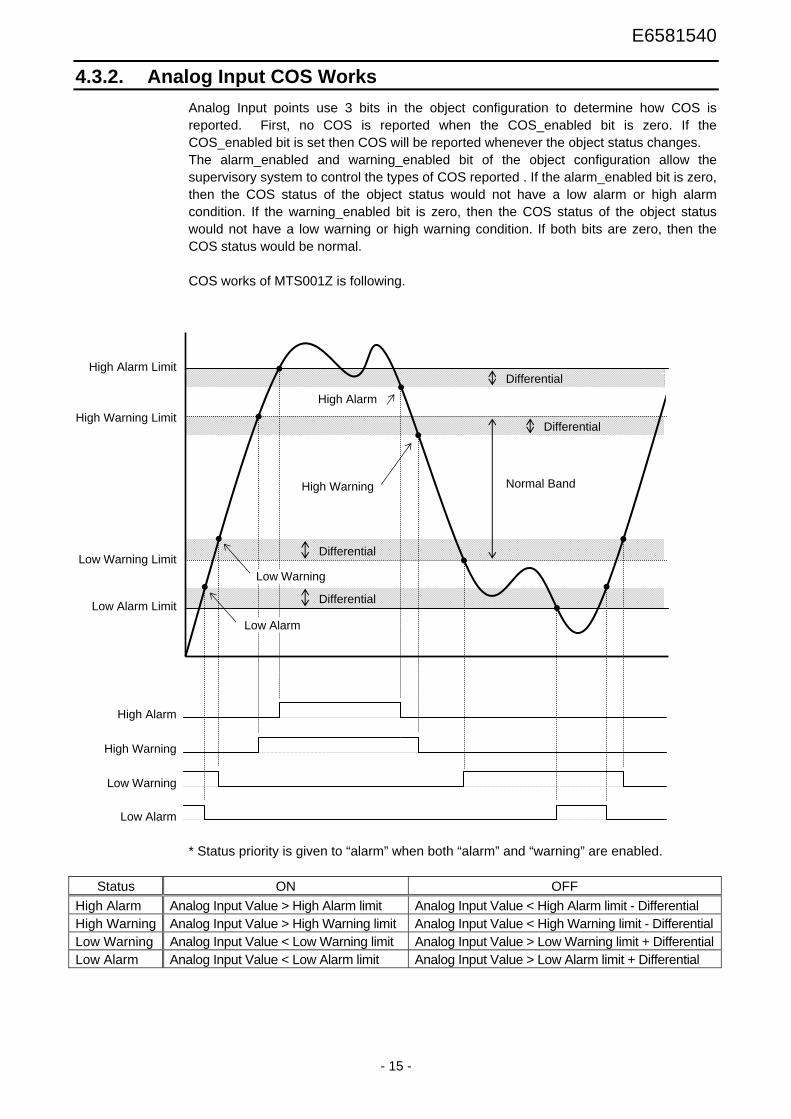
4.3.2. Analog Input COS Works Analog Input points use 3 bits in the object configuration to determine how COS is reported. First, no COS is reported when the COS_enabled bit is zero. If the COS_enabled bit is set then COS will be reported whenever the object status changes. The alarm_enabled and warning_enabled bit of the object configuration allow the supervisory system to control the types of COS reported . If the alarm_enabled bit is zero, then the COS status of the object status would not have a low alarm or high alarm condition. If the warning_enabled bit is zero, then the COS status of the object status would not have a low warning or high warning condition. If both bits are zero, then the COS status would be normal. COS works of MTS001Z is following.
* Status priority is given to “alarm” when both “alarm” and “warning” are enabled.
Status ON OFF High Alarm Analog Input Value > High Alarm limit Analog Input Value < High Alarm limit - Differential High Warning Analog Input Value > High Warning limit Analog Input Value < High Warning limit - DifferentialLow Warning Analog Input Value < Low Warning limit Analog Input Value > Low Warning limit + DifferentialLow Alarm Analog Input Value < Low Alarm limit Analog Input Value > Low Alarm limit + Differential
High Alarm Limit
Normal Band
High Warning Limit
Low Warning Limit
Low Alarm Limit
Differential
High Alarm
High Warning
Low Warning
Low Alarm
High Warning
High Alarm
Low Warning
Low Alarm
Differential
Differential
Differential

E6581540
- 16 -
4.4. Binary Input Object Binary Input Object is used for the status of VF-PS1, and the monitor of a logic input terminal. COS alarm and warning functions are also enabled. Overriding of analog inputs is not supported (“A” response).
Table 6 Binary Input Objects Table Object number
Object name VF-PS1 Contents
0 RO1ACT FL (TB) 0 = OFF, 1= ON 1 RO2ACT RY (TB) 0 = OFF, 1= ON 2 DI1ACT F (TB) 0 = OFF, 1= ON 3 DI2ACT R (TB) 0 = OFF, 1= ON
4 * - - - 5 RUNSTOP - 0 = Stop, 1= Run 6 FWDREV - 0 = Fwd, 1= Rev 7 FAULT - 1 = Tripped 8 HANDAUTO - 1 = Serial communication 9 MAINTREQ - 1 = Cumulative operation alarming 10 DRIVEREADY - 0 = Start-up, 1 = Standby 11 ATSETPOINT - 1 = Achieved 12 RO3ACT OUT2 0 = OFF, 1= ON 13 RO4ACT ** R2 0 = OFF, 1= ON 14 RO5ACT ** OUT5 0 = OFF, 1= ON 15 RO6ACT ** OUT6 0 = OFF, 1= ON 16 DI4ACT RES 0 = OFF, 1= ON 17 DI5ACT S1 0 = OFF, 1= ON 18 DI6ACT S2 0 = OFF, 1= ON 19 DI7ACT S3 0 = OFF, 1= ON 20 DI8ACT RR/S4 0 = OFF, 1= ON 21 DI9ACT ** LI5 0 = OFF, 1= ON 22 DI10ACT ** LI6 0 = OFF, 1= ON 23 DI11ACT ** LI7 0 = OFF, 1= ON 24 DI12ACT ** LI8 0 = OFF, 1= ON
* Reserved (The response is “A”). ** These are enabled with ETB004Z (Expansion IO Card option).

E6581540
- 17 -
4.4.1. Binary Input Attribute
Table 7 Binary Input Attribute Table Attribute Type Contents
1 Byte
Object Configuration Bit 0 = COS_enabled (1) Bit 1 = normal state Bit 2 = unused Bit 3 = alarm_enabled (1) Bit 4 = unused Bit 5 = unused Bit 6 = unused Bit 7 = unused
2 Byte
Object Status Bit 0 = reliable (0) / unreliable (1) Bit 1 = override active (1) Bit 2 = unused Bit 3 = unused Bit 4 = normal (0) / alarm (1) Bit 5 = normal (0) / trouble (1) (JCI use only) Bit 6 = current state Bit 7 = unused
3 Integer Debouncing Value in Msec (1-65535) (JCI use only) 4 Integer32 Accumulator value (JCI use only)
* Added shading functions are not supported (The response is “N10”).
4.5. Binary Input COS Works First, no COS is reported when the COS_enabled bit is zero. If the COS_enabled bit is set then COS will be reported whenever the object status changes. The alarm_enabled bit of the object configuration allow the supervisory system to control the types of COS reported. If the alarm_enabled bit is zero, then the current status of the object status would never have the normal/alarm bit set to alarm. This bit is set to alarm when the normal state of the object configuration does not match the current state of the object status.

E6581540
- 18 -
4.6. Analog Output Object Analog Output is used for the speed reference of VF-PS1 etc. COS alarm and warning functions are also enabled. Overriding of analog outputs will be accepted and acknowledged with the active override flag set. Upon release of the override command, the analog output point will reset the active override flag, retain the override value, and not return to its pre-override value.
Table 8 Analog Output Objects Table Object number
Object name Contents Units
0 INPUTREF Speed reference from Bus * % 1 ACCELTIME Acceleration time 0.1s 2 DECELTIME Deceleration time 0.1s 3 MBOXPARAM Refer to section 4.9. - 4 MBOXVALUEWRITE Refer to section 4.9. - 5 AO1COMMAND ** FM % 6 AO2COMMAND ** AM % 7 AO3COMMAND *** MON1 % 8 AO4COMMAND *** MON2 %
* 100% = vl(Base frequency), fh(Maximum frequency) limits this value. ** 0-2047(100%) *** 0-2047(100%), these are enabled with ETB004Z (Expansion IO Card option).

E6581540
- 19 -
4.6.1. Analog Output Attribute
Table 9 Analog Output Attribute Table Attribute Type Contents
1 Byte
Object Configuration Bit 0 = COS_enabled (1) Bit 1 = unused Bit 2 = unused Bit 3 = unused Bit 4 = unused Bit 5 = unused Bit 6 = unused Bit 7 = unused
2 Byte
Object Status Bit 0 = reliable (0) / unreliable (1) Bit 1 = override active (1) Bit 2 = saturated high (1) (JCI use only) Bit 3 = saturated low (1) (JCI use only) Bit 4 = unused Bit 5 = unused Bit 6 = unused Bit 7 = unused
3 Float Current Value 4 Float Low Linear Ranging Parameter (JCI use only) 5 Float High Linear Ranging Parameter (JCI use only)
* Added shading functions are not supported (The response is “N10”).
4.6.2. Analog Output COS Works Analog Output and Binary Output points have simple COS. If the COS_enabled bit is set then COS will be reported whenever the object status changes.

E6581540
- 20 -
4.7. Binary Output Object Binary Output is used for the run/stop of VF-PS1 etc. COS alarm and warning functions are also enabled. Overriding of analog outputs will be accepted and acknowledged with the active override flag set. Upon release of the override command, the binary output point will reset the active override flag, retain the override value, and not return to its pre-override value.
Table 10 Binary Output Objects Table Object number
Object name VF-PS1 Contents
0 RO1CMD FL (TB) *** 0 = OFF, 1 = ON (f130 = 38) 1 RO2CMD OUT1 *** - 2 RUNSTOPCMD - 0 = Stop, 1= Run 3 FWDREVCMD - 0 = Fwd, 1= Rev 4 FAULTRESET * - 1 = Reset 5 MBOXREAD - Refer to section 4.9. 6 MBOXWRITE - Refer to section 4.9. 7 SP1PRESET - Preset speed operation frequencies 18 SP2PRESET - Preset speed operation frequencies 29 SP3PRESET - Preset speed operation frequencies 310 FRCMDMOD - 1 = Metasys® N2 Enabled 11 RSCMDMOD - 1 = Metasys® N2 Enabled 12 RO3CMD OUT2 *** - 13 RO4CMD ** R2 *** - 14 RO5CMD ** OUT5 *** - 15 RO6CMD ** OUT6 *** -
* After reset, this value return to 0. ** These are enabled with ETB004Z (Expansion IO Card option). *** Before using these, as shown in the following table, it is necessary to set up Output
terminal selection.
Terminal Parameter of Output terminal selection Value
FL f132 92 (Inversion: 93) OUT1 f130 94 (Inversion: 95) OUT2 f131 96 (Inversion: 97)
R2 f138 98 (Inversion: 99) OUT5 f136 100 (Inversion: 101) OUT6 f137 102 (Inversion: 102)

E6581540
- 21 -
4.7.1. Binary Output Attribute
Table 11 Binary Output Attribute Table Attribute Type Contents
1 Byte
Object Configuration Bit 0 = COS_enabled (1) Bit 1 = normal state Bit 2 = unused Bit 3 = unused Bit 4 = unused Bit 5 = unused Bit 6 = unused Bit 7 = unused
2 Byte
Object Status Bit 0 = reliable (0) / unreliable (1) Bit 1 = override active (1) Bit 2 = unused Bit 3 = unused Bit 4 = normal (0) / alarm (1) (JCI use only) Bit 5 = normal (0) / trouble (1) (JCI use only) Bit 6 = current state Bit 7 = unused
3 Integer Minimum On-time (sec) (0-65535) 4 Integer Minimum Off-time (sec) (0-65535) 5 Integer Maximum Cycles/Hour 6 Integer Interstage on delay(sec)(0-65535) (JCI use only) 7 Integer Interstage off delay(sec)(0-65535) (JCI use only)
* Added shading functions are not supported (The response is “N10”).
4.7.2. Binary Output COS Works Binary Output and Binary Output points have simple COS. If the COS_enabled bit is set then COS will be reported whenever the object status changes.

E6581540
- 22 -
4.8. Error Message Format The negative responses have the following format, followed by the error codes and their meaning. CHAR1 Start of message................................................ N CHAR2 Error code .......................................................... (Refer to Table 12) CHAR1 End of message................................................. (CR)
Table 12 Error Code Table Error Table Contents
00 MTS001Z has reset and is waiting for the “Identify Yourself” command. 01 Undefined Command error. 02 Invalid message (include checksum error). 05 Data field error: message size not correct for command type.
10
Invalid Data: The fields contains a value that is out of the expected range. Confirm that the requested point exists or a commanded value is not out of range.
E6581540
- 23 -
4.9. VF-PS1 Parameter access Using below Metasys® N2 objects, inverter parameters can be read and written. Table 13 Error Code Table
Object Object number
Object name Note
Analog Output 3 MBOXPARAM The communication number (hex.) of the access parameter is set.
Analog Input 13 MBOXVALUEREAD The read value is set. Analog Output 4 MBOXVALUEWRITE Set the write value.
Binary Output 5 MBOXREAD The parameter value specified by MBOXPARAM is read.
Binary Output 6 MBOXWRITE The value of MBOXVALUEWRITE is written to the parameter specified by MBOXPARAM.
Example 1) Read the deceleration time (dec, Comm. No. 0010)
1. Override “16” as the communication number to MBOXPARAM (Analog Output Object - 3). * The communication number uses the value of a decimal number set to
“10” by the hexadecimal number. 0x0010 = 16 dec. 2. Override “1” to MBOXREAD (Binary Output Object - 5). 3. The read value set to MBOXVALUE (READ Analog Input Object - 13). Its unit
is 0.1s. Example 2) Write “50.0Hz” to VIB input point 2 (f213, Comm No. 0213)
1. Override “531” as the communication number to MBOXPARAM(Analog Output Object - 3). * 0x0213 = 531 dec.
2. Override “5000” to MBOXVALUEWRITE (Analog Output Object - 4). * 5000 = 50.00Hz, unit is 0.01Hz
3. Override “1” to MBOXWRITE (Binary Output Object - 6).
Example 3) Read the input voltage (fd04, Comm No. fd04) 1. Override “64772” as the communication number to MBOXPARAM(Analog Output
Object - 3). * 0xfd04 = 64772 dec.
2. Override “1” to MBOXREAD (Binary Output Object - 5). 3. The read value set to MBOXVALUE (READ Analog Input Object - 13). Its unit is
0.01%.
* When the communication is failed, overrided “1” of MBOXREAD or MBOXWRITE is kept (“A” response). Please check the value of MBOXREAD or MBOXWRITE after the parameter access.
* The writing value using MBOXWRITE writes to EEPROM at VF-PS1 (it is kept after VF-PS1 power off). So, frequent writing decrease the life of EEPROM (10,000 times).

E6581540
- 24 -
5. VF-PS1 Trip code
Code Data
(Dec.) Data
(Hex.) Description Display
0 00H No error nerr
1 01H Over-current during acceleration oc1
2 02H Over-current during deceleration oc2
3 03H Over-current during constant speed operation oc3
4 04H Over-current in load at startup ocl
5 05H U-phase arm overcurrent ocai
6 06H V-phase arm overcurrent oca2
7 07H W-phase arm overcurrent oca3
8 08H Input phase failure ephi
9 09H Output phase failure epho
10 0AH Overvoltage during acceleration op1
11 0BH Overvoltage during deceleration op2
12 0CH Overvoltage during constant speed operation op3
13 0DH Over-LOAD in inverter ol1
14 0EH Over-LOAD in motor ol2
15 0FH Dynamic braking resistor overload olr
16 10H Overheat oh
17 11H Emergency stop e
18 12H EEPROM fault eep1
19 13H Initial read error eep2
20 14H Initial read error eep3
21 15H Inverter RAM fault err2
22 16H Inverter ROM fault err3
23 17H CPU fault err4
24 18H Communication time-out error err5
25 19H Gate array fault err6
26 1AH Output current detector error err7
27 1BH Option error err8
29 1DH Low current operation status uc
30 1EH Undervoltage (main circuit) up1
32 20H Over-torque trip ot
33 21H Ground fault trip ef1
34 22H Ground fault trip ef2
36 24H Dynamic braking abnormal element ocr
(Continued overleaf)

E6581540
- 25 -
(Continued) Code
Data (Dec.)
Data (Hex.)
Description Display
37 25H Overcurrent during acceleration (element overheat) oc1p
38 26H Overcurrent during deceleration (element overheat) oc2p
39 27H Overcurrent during fixed speed operation (element overheat) oc3p
40 28H Tuning error etn
41 29H Inverter type error etyp
42 2AH Analog input terminal overvoltage e-10
43 2BH Abnormal brake sequence e-11
44 2CH Disconnection of encoder e-12
45 2DH Speed error e-13
46 2EH External thermal oh2
47 2FH Step-out (for PM motors only) sout
50 32H Terminal input error e-18
51 33H Abnormal CPU2 communication e-19
52 34H V/f control error e-20
53 35H CPU1 fault e-21
54 36H Abnormal logic input voltage e-22
55 37H Option 1 error e-23
56 38H Option 2 error e-24
57 39H Stop position retaining error e-25
58 3AH CPU2 fault e-26
61 3DH Control circuit option error e-29
84 54H f410 tuning error etn1
85 55H f412 tuning error etn2
86 56H vl, vlv, f405 - 407 Motor constant setting error etn3

E6581540
- 26 -
6. Specifications
< Environmental specification > Item Specification
Model number MTS001Z Service environment VF-PS1 compliant Ambient temperature -10 to +60℃ Storage temperature -25 to +65℃
Relative humidity 20 to 93% (No condensation and absence of vapor)
Vibration 5.9m/s2 (0.6G) or less (10 to 55 Hz) (To be complied with JIS C0040.)
<MTS001Z network specification > Item Specification
Maximum node 255 nodes (32 nodes per segment) Communication baud rate 9600bps
Bias resistor and termination Local bias resistors are mounted. Termination resistor (120 ohm) can be select by SW.
Terminal block Detachable terminal block 4-pole (5.08mm pitch)
Manufacturer: PHOENIX CONTACT Type-Form : MSTB 2,5/4-STF-5.08
- 26E -