FRANKLIN INSTITUTE LIBRARY
PHILADELPHIA
Class <^.S.Mr Book hl..J^..(^.. Accession.../^.
out, all unbound periodicals, and such text book.^ as ought to be foundin a library of reference except when rfequircMl by Committees of theInstitute, or by members or holders of seooa^ class stock, who haveobtained the sanction of the Committee. ThJ^eCond class shall includethose books intended for circulation.
Artici.e VI.—The Secretary shall have authority to loan to Membersand to holders of second class stock, anv work belonging to the s-kcond(;la.ss, subject to the following regulations:
Section A—No individvial shall be permitted to have more than twobooks out at one time, without a written permission, signed by at leasttwo members of the Library Committe ; nor shall a book be kept outmore than two wkeks
; but if no one has applied for it, the former bor-rower may renew the loan. Should any person have applied for it, thelatter shall have the preference.
Section 2.~K fink ok ten cents per week shall be exacted for thedetention of a book beyond the limited time
; and if a book be not re-turned withm three months it shall be deemed lo.st, and the borrowershall, in addition to his fines, forfeit its value.
Section 3.—f^honXd any book be returned injured, the borrower shallpay for the injury, or replace the book, as the Library Committee maydirect
;and if one or more books, belonging to a set or sets, be lost, the
borrower shall replace them or make full restitution.AiiTK-i.E VIL—Any person removing from the Hall, without permis-
sion from the proper authorities, any book, newspaper or other propertyin charge of the Library Committee, shall be reported to the Committee,who may inflict any fine not exceeding twenty-five dollars.Aktjcle Viri.—No member or holder o'f second class stock, whose
annual contribution for the' current year shall be unpaid or who is inarrears for fines, shall be entitled to the privileges of the Library orKeadmg Room.Article IX.—If any member or holder of second class stock, shall
refuse or neglect to comply with the foregoing rules, it shall be the dutyof the Secretary to report him to the Committee on the Library.Article X.—Any Member or holder of second class stock^ detected
111 mutilating the newspapers, pamphlets or books belonging to the Insti-tute shall be deprived of his right of membership, and the name of the'offender shall be made public.


THE STEEL SQUARE.

THE CARPENTERS'
Steel Square,AND
ITS USES.BEING A DESCEIPTION OF THE SQUAKE, AND ITS USES IN OBTAINING"
THE LENGTHS AND BEVELS OF ALL KINDS OF
RAFTERS, flIPS, GROINS, BRACES, BRACKETS, PUR-LINS, COLLAR-BEAMS, AND JACK-RAFTERS;
ALSO, ITS APPLICATION IN OBTAINING THE BEVELS ANDCUTS FOR HOPPERS, SPRING MOULDINGS, OCTAGONS,
STAIRS, DIMINISHED STILES, ETC., ETC., ETC.
ILLUSTRATED BY OVER FIFTY WOOD-CUTS.
Editor'' Sf ''t^if '"'j^tflci^ 'hu'd ' PFJodworier}'''
'
NEW YOEK:THE INDUSTRIAL PUBLICATION COMPANY.
1880.COPTBIGHT 6ECCKED.
Some time ago, the author of this little work contributed a series
of papers on the Steel Squake and Its Uses, to the American
Builder, and since their appearance, he has received hundreds of
letters from as many persons residing in various parts of the
United States, Canada, Australia and New Zealand, in which the
writers requested him to publish the papers in book form. Partly
in compliance with these requests, and partly at the solicitation
of personal friends, together with a knowledge that a cheap but
thorough work of the kind, would be of service to all persons who
have occasion to use a steel square, he has consented, with the aid
of the present enterprising pubUshers, to issue the work as now
offered.
It is only of late years that American workmen have begun
fully to understand the capabilities of the steel square ; and even
now, only a few of the best workmen have any idea of what can be
accomplished with it when in skilful hands.
It is not claimed that the rules und methods shown in this little
work are either new or original ;they have beenknown to advanced
workmen for many years past; but it is claimed that they have
never before been brought together and put in so handy a shape as
1^

iv PREFACE,
in the present book ; and it is furttier claimed tliat many of the
rules herein illustrated and explained, have never appeared in
print previous to the publication of the papers on the subject in the
magazine referred to above.
Should this little volume prove of service to the man who toils
with axe, saw and plane, for his daily bread, and profitable to the
publishers who risk their money on its publication, it will havefulfilled its mission, as designed by
THE AUTHOE.
New York, 1880.
CONTENTS.
PAKT I.
Preliminary . - - - -
The Square as a Constructive Tool
Lines and Scaies
Description of Scales . . .
Board Rule - -
Brace Eule - - - - -
Octagon Scale - - - -
Fence for Square - - - -
Application of Square - - -
To lay out Eafters - - --
To Cut Collar Beams, Gables, Pitches, etc.
Hip Rafters, Cripples, etc.
Backing for Hips
How to Cut a Mitre Box -
Stairs and Strings . - -
Miscellaneous Rules . --
Board Measure - - - -
Proportion of Circles
Centering Circles . . -
How to Describe an Ellipse
How to Describe a Parabola
Bevels for Hoppers
Bisecting Circles
Cutting Spring Mouldings

vi C O K T E N T S.
PAET II.
PAGETheoretical Eafters - - - - - - _ 46
Bevels and Lengths for Hips, Jacks, and Purlins - - 48
Divisions of Widths - - - - . . .50Bisection of Angles 50
Diminishing Stiles - - - - - . .51
PAET III.
Octagons; - - - - - . -52
To Find the Diagonal of a Square - - - - 5G
Polygons 57
Circles - -- -- -- .58To Lay out Anglos - - - . . - 60
Bevels of Hoppers ------ 60
Widths of Sides and Ends of Hoppers - - - - 61
Corner Pieces for Hoppers ----- 62
Roofing 63
Lengths and Bevels of Hip-Rafters - - - - 64
Backing of Hips ------- 64
Irregular Hip Roofs ------ 65
Side-bevels of Jacks - - - - . . . 66
Trusses ------- .g?
THE CARPENTERS' STEEL SQUARE,
AND ITS USES. /f ^^'^
PART T.
Preliminary.—There is nothing of more importance to
a young man who is learning the business of house-joinery
and carpentry, than that he should make himself thoroughly
conversant with the capabilities of the tools he employs. It
may be that, in some of the rules shown in this work, the
result could be attained much readier with other aids than
the square ; but the progressive mechanic will not rest satis-
fied with one method of performing operations when others
are within his reach.
In the hand of the intelligent mechanic the square be-
comes a simple calculating machine of the most wonderful
capacity, and by it he solves problems of the kinds continu-
ally arising in mechanical work, which by the ordinary
methods are more difficult to perform.
The great improvement which the arts and manufactures
have attained within the last fifty years, renders it essential
that every person engaged therein should use his utmost
exertions to obtain a perfect knowledge of the trade he
73

8 THE STEEL SQUARE
professes to follow. It is not enough, nowadays, for a per-
son to have attained the character of a good workman
;
that phrase implies that quantum of excellence, which con-
sists in working correctly and neatly, under the directions
of others. The workman of to-day, to excel, must under-
stand the principles of his trade, and be able to apply them
correctly in practice. Such an one has a decided advan-
tage over his fellow-workman ; and if to his superior know-
ledge he possesses a steady manner, and industrious habits,
his efforts cannot fail of being rewarded.
It is no sin not to know much, though it is a great one
not to know all we can, and put it all to good use. Yet,
how few mechanics there are who will know all they can ?
Men apply for employment daily who claim to be finished
mechanics, and profess to be conversant with all the ins
and outs of their craft, and who are noways backward in
demanding the highest wages going, who, when tested, are
found wanting in knowledge of the simplest formulas of
their trade. They may, perhaps, be able to perform a good
job of work after it is laid out for tficm by a more compe-
tent hand; they may have a partial knowledge of the uses
and application of their tools;
but, generally, their know-
ledge ends here. Yet some of these men have worked at
this trade or that for a third of a century, and are to all
appearances, satisfied with the little they learned when they
were apprentices. True, mechanical knowledge was not
always so easily obtained as at present, for nearly all works
on the constructive arts were written by professional archi-
tects, engineers, and designers, and however unexception-
able in other respects, they were generally couched in such
language, technical and mathematical, as to be perfectly
AND ITS USES. 9
unintelligible to the majority of workmen ; and instead of
acting as aids to the ordinary inquirer, they enveloped in
mystery the simplest solutions of every-day problems, dis-
couraging nine-tenths of workmen on the very threshold of
inquiry, and causing them to abandon further efforts to
master the intricacies of their respective trades.
Of late years, a number of books have been published,
in which the authors and compilers have made commend-able efforts to simplify matters pertaining to the arts of car-
pentry and joinery, and the mechanic of to-day has not
the difficulties of his predecessors to contend with. Theworkman of old could excuse his ignorance of the higher
branches of his trade, by saying that he had no means of
acquiring a knowledge of them. Books were beyond his
reach, and trade secrets were guarded so jealously, that only
a limited few were allowed to know them, and unless he wasmade of better stuff than the most of his fellow-workmen,
he was forced to plod on in the same groove all his days.
Not so with the mechanic of to-day ; if he is not well
up in all the minutae of his trade, he has but himself to
blame, for although there is no royal road to knowledge,
there are hundreds of open ways to obtain it ; and the
young mechanic who does not avail himself of one or other
of these ways to enrich his mind, must lack energy, or be
altogether indifferent about his trade, and may be put downas one who will never make a workman.
I have thought that it would not be out of place t9 pre-
face this work on the " Steel Square," with the foregoing
remarks, in the hope that they may stimulate the youngmechanic, and urge him forward to conquer what at best
are only imaginary difficulties. A willing heart and a

lO THE STEEL SQUARE
clear head will most assuredly win honorable distinction in
any trade, if they are only properly used.
The "Square," as a constructive tool, must of necessity
have found a place in the " kit " of the earliest builders.
Evidences of its presence have been found in the ruins of
pre-historic nations, and are abundant in the remains of
ancient Petra, Ninevah, Babylon, Etruria, and India. South
American ruins of great antiquity in Brazil, Peru, and other
places, show that the unknown races that once in-
habited the South American Continent, were famiHar with
many of the uses of the square. Egypt, however, that
cradle of all the arts, furnishes us with the most numerous,
and, perhaps, the most ancient evidences of the use of the
square;paintings and inscriptions on the rock-cut tombs,
the temples, and other works, showing its use and appli-
cation, are plentiful. In one instance, a whole " kit " of
tools was found in a tomb at Thebes, which consisted of
mallets, hammers, bronze nails, small tools, drills, hatchets,
adzes, squares, chisels, etc.; one bronze saw and one adze
has the name of Thothmes III, of the i8th dynasty, stamped
on their blades, showing that they were made nearly 3,500
years ago. The constructive and decorative arts at that
time Avere in their zenith in Egypt, and must have taken at
least 1,000 years to reach that stage. Consequently, the
square must have been used by the workmen of that coun-
try, at least, four thousand years ago.
The British Museum contains many tools of pre-historic
origin, and the square is not the least of them. Hercu-
laneum and Pompeii contribute evidences of the importance
of this useful tool. On some of the paintings recently dis-

AND ITS USES. 11
covered in those cities, the different artisans can be seen at
home in their own workshops, with their work-benches,
saw-horses, tools, and surroundings, much about the same
as we would find a small carpenter shop of to-day, where
all the work is done by hand ; the only difference being a«
change in the form of some of the tools, which, in some
instances, had been better left as these old workmen de-
signed them.
Lines and Scales.—The lines and figures formed onffiF'
squares of different make, sometimes vary, both as to their
position on the square, and their mode of application, but
a thorough understanding of the application of the scales
and lines shown on any first-class tool, will enable the
student to comprehend the use of the hnes and figures ex-
hibited on other first-class squares.
To insure good results, it is necessary to be careful in
the selection of the tool. The blade of the square should
be 24 inches long, and two inches wide, and the tongue
from 14 to 18 inches long and inches wide. The
tongue should be exactly at right angles with the blade, or
in other words the " square " should be perfecdy square.
To test this question, get aboard, about 12 or 14 inches
wide, and four feet long, dress it on one side, true up one edge
as near straight as it is possible to make it. Lay the board
on the bench, with the dressed side up, and the trued edge
towards you, then apply the square, with the blade to the
left, and mark across the prepared board with a penknife
blade, pressing close against the edge of the tongue ;this
process done to your satisfaction, reverse the square, and
move it until the tongue is close up to the knife mark;if

12 THE STEEL SQUARE
you find that the edge of the tongue and mark coincide, it
is proof that the tool is correct enough for your purposes.
The next thing to be considered is the use of the figures,
Hnes, and scales, as exhibited on the square. It is sup-
posed that the ordinary divisions and sub-divisions of theinch, into halves, quarters, eighths, and sixteenths are un-derstood by the student; and that he also understandshow to use that part of the square that is sub-divided into
twelfths of an inch. This being conceded, we now pro-
ceed to describe the various rules as shown on goodsquares.
Description.—On the Frontispiece we show both sides
of one of the best squares in the market. The following
instructions refer to this plate.
The diagonal scale is on the tongue at the junction withblade, Fig. i, and is for taking off hundredths of an inch.
The lengths of the lines between the diagonal and the
perpendicular, are marked on the latter. Primary divisions
are tenths, and the junction of the diagonal lines with the
longitudinal parallel lines enables the operator to obtain
divisions of one hundredth part of an inch; as, for example,if we wish to obtain twenty-four hundredths of an inch, weplace the compasses on the " dots " on the fourth parallel line,
which covers two primary divisions, and a fraction, or four
tenths, of the third primary division, which added' togethermakes twenty-four hundredths of an inch. Again, if wewish to obtain five tenths and seven hundredths, we oper-
ate on the seventh line, taking five primaries and the frac-
tion of the sixth where the diagonal intersects the parallel
AND ITS USES. 13
line, as shown by the " dots," on the compasses, and this
gives us the distance required.
The use of this scale is obvious, and needs no further
explanation.
Board Measure —Under the figure 12, Fig. 2, on the outer
edge of the blade, the length of the boards, plank, or
scantling to be measured is given, and the answer in feet
and inches is found under the inches in width that the
board, etc., measures. For example, take a board nine
feet long and five inches wide; then under the figure 12,
on the second line will be found the figure 9, which is the
length of the board ; then run along this line to the figure
directly under the five inches (the width of the board), and
we find three feet nine inches, which is the correct answer
in " board measure." If the stuff is two inches thick, the
sum is doubled ; if three inches thick, it is trebled, etc., etc.
If the stuff is longer than any figures shown on the square,
it can be measured by dividing and doubling the result.
This rule is calculated, as its name indicates, for board
measure, or for surfaces i inch in thickness. It may be ad-
vantageously used, however, upon timber by multiplying
the result of the face measure of one side of a piece by its
depth in inches. To illustrate, suppose it be required to
measure a piece of timber 25 feet long, 10 x 14 inches in
size. For the length we will take 12 and 13 feet. For the
width we will take 10 inches, and multiply the result by
14. By the rule a board 12 feet long and 10 inches wide
contains 10 feet, and one 13 feet long and 10 inches wide,
ID feet 10 inches. Therefore, a board 25 feet long and 10
inches wide must contain 20 feet and 10 inches. In

H THE STEEL SQUARE
the timber above described, however, we have what is
equivalent to 14 such boards, and therefore we multiply
this result by 14, which gives 291 feet and 8 inches, the
board measure.
Fig. 3.
The " board measure," as shown on the portion of the
square. Fig. 3, gives the feet contained in each board ac-
cording to its length and width. This style of figuring
squares, for board measure, is going out of date, as it
gives the answer only in feet.
Brace Rule.—The " brace rule " is always placed on the
tongue of the square, as shown in the central space at x.
Fig. I.
This rule is easily understood ; the figures on the left ofthe line represent the " run " or the length of two sides of aright angle, while the figures on the right represent the
exact length of the third side of a right-angled triangle, in
inches, tenths, and hundredths. Or, to explain it in another
way, the equal numbers placed one above the other maybe considered as representing the sides of a square, andthe third number to the right the length of the diagonal of
that square. Thus the exact length of a brace from point
to point having a run of 33 inches on a post, and a run ofthe same on a girt, is 46-67 inches. The brace rule varies

AND ITS USES. 15
somewhat in the matter of the runs expressed in different
squares. Some squares give a few brace lengths of which
the runs upon the post and beam are unequal.
Octagonal Scale.—The " octagonal scale," as shown on
the central division of the upper portion of blade, is on the
opposite side of the square to the " brace rule, " and runs
along the centre of the tongue as at s.s. Its use is as iol-; ;v
lows : Suppose a stick of timber ten inches square. : Make
a centre hne, which will be five inches from eac|i edge ; set
a pair of compasses, putting one leg on any of, the^ main
divisions shown on the square in this scale, and the ,.,othe]^-.
^
leg on the tenth subdivision. This division, pricked off"
from the centre line on the timber on each side, will give
the points for the gauge-lines. Gauge from the corners
both ways, and the lines for making the timber octagonal
in its section are obtained. Always take the same number
of spaces on your compasses as the timber is inches square
from the centre line. Thus, if a stick is twelve inches
square, take twelve spaces on the compasses ; if only six
inches square, take six spaces on the compasses, etc., etc.
The rule always to be observed is as follows : Set off from
each side of the centre line upon each face as many spaces
by the octagon scale as the timber is inches square. For
timbers larger in size than the number of divisions in the
scale, the measurements by it may be doubled or trebled,
as the case may be.
I have now fully described all the lines, figures, and
scales that are usually found on the better class of squares
now in use ;but, I may as well here remark that there are
squares in use of an inferior grade, that are somewhat dif-

i6 THE STEEL SQUARE
ferently figured. These tools, however, are such as can
not be recommended for the purposes of the scientific
carpenter or joiner.
Fence.—A necessary appendage to the steel square in
solving mechanical problems, is, what I call, for the want
of a better name, an adjustable fence. This is made out
of a piece of black walnut or cherry 2 inches wide, and 2
feet 10 inches long (being cut so that it will pack in a tool
chest), and inches thick; run a gauge line down the
centre of both edges; this done, run a saw kerf cutting
down these gauge lines at least one foot from each end,
leaving about ten inches of solid wood in the centre of
fence. We now take our square and insert the blade in the
saw kerf at one end of the fence, and the tongue in the
kerf, at the other, the fence forming the third side of a
right-angle triangle, the blade and the tongue of the square
forming the other two sides. A fence may be made to do
r ' i
Fig. 4.
pretty fair service, if the saw kerf is all cut from one end
as shown at Fig. 4. The one first described, however, will
be found the most serviceable. The next step will be to
make some provision for holding the fence tight on the
square ; this is best done by putting a No. 10 inch
screw in each end of the fence, close up to the blade and
tongue;having done this, we are ready to proceed to busi-
ness.
AND ITS USES. 17
Application.—The fence being made as desired, in either
of the methods mentioned, and adjusted to the square, work
can be commenced forthwith.
The first attempt will be to make a pattern for a brace,
for a four-foot " run." Take a piece of stuff already pre-
pared, six feet long, four inches wide and half-inch thick,
gauge it three-eighths from jointed edge.
Take the square as arranged at Fig. 5, and place it on
the prepared stuff as shown at Fig. 6. Adjust the square
so that the twelve-inch lines coincide exactly with the
gauge line o, o, o, o. Hold the square firmly in the posi-
tion now obtained, and slide the fence up the tongue and
blade until it fits snugly against the jointed edge of the
prepared stuff, screw the fence tight on the square, and be
sure that the 12 inch marks on both the blade and the
tongue are in exact position over the gauge-line.
I repeat this caution ^ because the successful completion
of the work depends on exactness at this stage.
We are now ready to lay out the pattern. Slide the
square to the extreme left, as shown on the dotted lines at
x, mark with a knife on the outside edges of the square,
cutting the gauge-line. Slide the square to the right until
the 1 2 inch mark on the tongue stands over the knife markon the gauge-line ; mark the right-hand side of the square
cutting the gauge-line as before, repeat the process four
times, marking the extreme ends to cut off, and we have
the length of the brace and the bevels.
Square over, with a try square, at each end from the
gauge-line, and we have the toe of the brace. The lines,
s, s, shown at the ends of the pattern, represent the tenons
that are to be left on the braces. This pattern is now com-
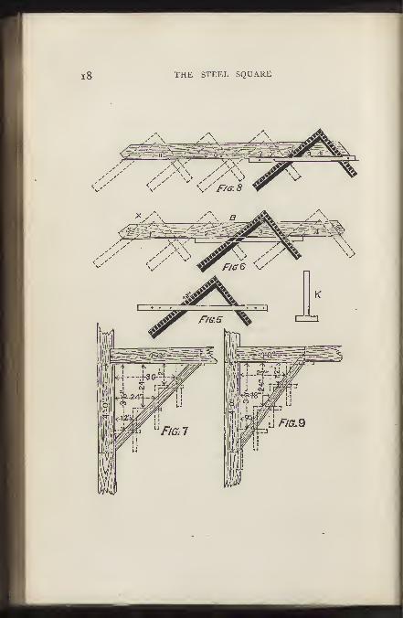

AND ITS USES. 19
plete ; to make it handy for use, however, nail a strip 2 inches
wide on its edge, to answer for a fence as shown at k, and
the pattern can then be used either side up.
The cut at Fig. 7, shows the brace in position, on a re-
duced scale. The principle on which the square works in
the formation of a brace can easily be understood from this
cut, as the dotted lines show the position the square was in
when the pattern was laid out.
It may be necessary to state that the " square," as now
arranged, will lay out a brace pattern for any length, if thfe
angle is right, and the rim equal. Should the brace be of
great length, however, additional care must be taken in the
adjustment of the square, for should there be any departure
from truth, that departure will be repeated every time the
square is moved, and where it would not affect a short run, it
might seriously affect a long one.
To lay out a pattern for a brace where the run on the
beam is three feet, and the run down the post four, proceed
as follows
:
Prepare a piece of stuff, same as the one operated on for
four feet run; joint and gauge it. Lay the square on the
left-hand side, keep the 12 inch mark on the tongue, over
the gauge-line, place the 9 inch mark on the blade, on the
gauge-line, so that the gauge-line forms the third side of a
right-angle triangle, the other sides of which are nine and
twelve inches respectively.
Now proceed as on the former occasion, and as shown
at Fig. 8, taking care to mark the bevels at the extreme
ends. The dotted lines show the positions of the square,
as the pattern is being laid out.
Fig. 9 shows the brace in position, the dotted lines show

20 THE STEEL SQUARE
where the square was placed on the pattern. It is well to
thoroughly understand the method of obtaining the lengths
and bevels of irregular braces. A little study, will soon
enable any person to make all kinds of braces.
If we want a brace with
a two feet run, and a four
feet run, it must be evident
that, as two is the half of
four, so on the square take
1 2 inches on the tongue, and
6 inches on the blade, apply
four times, and we have the
length, and the bevels of a
brace for this run.
^ For a three by four feet
" run, take 12 inches on the
^ tongue, and 9 inches on the
blade, and apply four times,
because, as 3 feet is ^ of four
feet, so 9 inches is ^ of 12
inches.
Rafters.—Fig. 10 shows
a plan of a roof, having
twenty-six feet of a span.
The span of a roof is the
distance over the wall plates
measuring from A to A, as shown in Fig. 10. It is also
the extent of an arch between its abutments.
There are tv/o rafters shown in position on Fig. 10, Theone on the left is at an inclination of quarter pitch, and

AND ITS USES.
marked B, and the one on the right,
marked C, has an inclination of one-third
pitch. These angles, or inclinations rather,
are called quarter and third pitch, respec-
tively, because the height from level of wall
plates to ridge of roof is one-quarter Dr one-
third the width of building, as the case
may be.
At Fig. 1 1 , the rafter B is shown drawn to
a larger scale;you will notice that this rafter
is for quarter pitch, and for convenience, it is
supposed to consist of a piece of stuff 2
inches by 6 inches by 1 7 feet. That portion
of the rafter that projects over the wall of the
building, and forms the eve, is three or more
inches in width, just as we please. Thelength of the projecting piece in this case is
one foot—it may be more or less to suit the
eve, but the Hne must continue from end to
end of the rafter, as shown on the plan, and
we will call this line our working line.
We are now ready to lay out this
rafter, and will proceed as follows : Weadjust the fence on the square the same as
for braces, press the fence firmly against
the top edge of rafter, and place the figure
12 inches on the left-hand side, and the
figure 6 in on the right-hand side, directly
over the working line, as shown on the
plan. Be very exact about getting the
figures on the line, for the quality of the

22 THE STEEL SQUARE
work depends much on this; when you are satisfied that
you are right, screw your fence tight to the square. Com-mence at No. I on the left, and mark off on the working
hne; then shde your square to No. 2, repeat the marking
and cont'nue the process until you have measured off
thirteen spaces, the same as shown by the dotted lines in
the drawing. The last Hne on the right-hand side will be
the plumb cut of the rafter, and the exact length required.
It will be noticed that the square has been applied to the
timber thirteen times.
The reason for this is, that the building is twenty-six feet
wide, the half of which is thirteen feet, the distance that
one rafter is expected to reach, so, if the building was thirty
feet wide, we should be obliged to apply the square fifteen
times instead of thirteen. We may take it for granted,
then, that in all cases where this method is employed to
obtain the lengths and bevels, or cuts of rafters, we must
apply the square half as many times as there are feet in the
w_idth of the building being covered. If the roof to be
covered is one-third pitch, all to be done is to take 12
inches on one side of the square and 8 inches on the other,
and operate as for quarter pitch.
We shall frequently meet with roofs much more acute
than the ones shown, but it will be easy to see how they
can be managed. For instance, where the rafters are at
right-angles to each other, apply the square the same as
for braces of equal run, that is to say, keep the 1 2 mark on
the blade, and the 12 mark on the tongue, on the working
line. When a roof is more acute, or " steeper " than a
right-angle, take a greater figure than twelve on one side
of the square, and twelve on the other.
AND ITS USES. 23
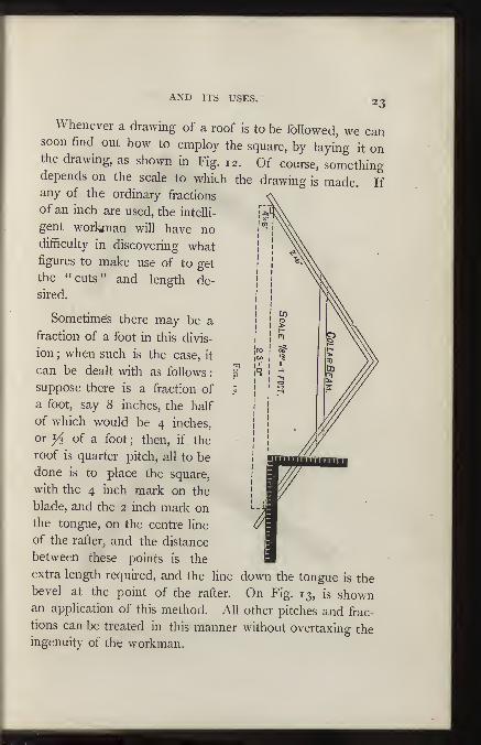
Whenever a drawing of a roof is to be foHowed, we cansoon find out how to employ the square, by laying it onthe drawing, as shown in Fig. 12. Of course, somethingdepends on the scale to which the drawing is made. Ifany of the ordinary fractions
of an inch are used, the intelli-
gent worlynan will have nodifficulty in discovering whatfigures to make use of to get
the "cuts" and length de-
sired.
Sometimes there may be a
fraction of a foot in this divis-
ion; when such is the case, it
can be dealt with as follows : S
suppose there is a fraction of «
a foot, say 8 inches, the half
of which would be 4 inches,
or yi of a foot; then, if the
roof is quarter pitch, all to be
done is to place the square,
with the 4 inch mark on the
blade, and the 2 inch mark onthe tongue, on the centre line
of the rafter, and the distance
between these points is the
extra length required, and the line down the tongue is thebevel at the point of the rafter. On Fig. 13, is shownan application of this method. All other pitches and frac-
tions can be treated in this manner without overtaxing theingenuity of the workman.

Fig. 14.
AND ITS USES. 25
Sufficient has been shown to enable the student, if he
has mastered it, to find the lengths and bevels of any com-
mon rafter;therefore, for the present, we will leave saddle
roofs, and try what can be done with the square in de-
termining the lengths and bevels of " hips," valleys,«!and
cripples.
Fig. 15.
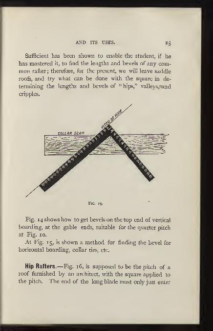
Fig. 14 shows how to get bevels on the top end of vertical
boarding, at the gable ends, suitable for the quarter pitch
at Fig. 10.
At Fig. 15, is shown a method for finding the bevel for
horizontal boarding, collar ties, etc.
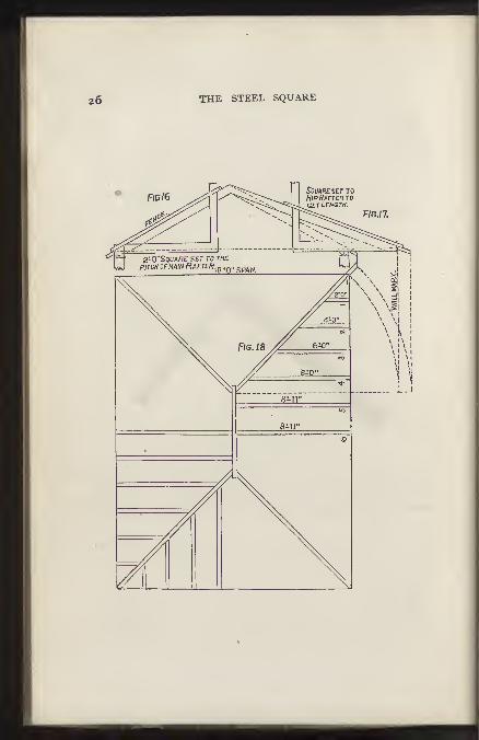
Hip Rafters.—Fig. 16, is supposed to be the pitch of a
roof furnished by an architect, with the square applied to
the pitch. The end of the long blade must only just enter
26 THE STEEL SQUARE

AND ITS USES. 27
the fence, as shown in the drawing, and the short end must
be adjusted to the pitch of the roof, whatever it may be.
Fig. 1 7 shows the square set to the pitch of the hip rafter.
The squares as set give the plumb and level cuts. Fig. 18
is the rafter plan of a house 18 by 24 feet; the rafters are
laid off on the level, and measure nine feet from centre of
ridge to outside of wall; there* should be a rafter pattern
with a plumb cut at one end, and the foot cut at the other,
got out as previously shown. (Figs. 16, 17, 18, P.) When the
rafter foot is marked, place the end of the long blade of the
square to the wall line, as in drawing, and mark across the
rafter at the outside of the short blade, and these marks onthe rafter pitch will correspond with two feet on the level
plan ; slide the square up the rafter and place the end of the
long blade to the mark last made, and mark outside the short
blade as before, repeat the application until nine feet are
measured off, and then the length of the rafter is correct
;
remember to mark off one-half the thickness of ridge-piece.
The rafters are laid off on part of plan to show the appearance
of the rafters in a roof of this kind, but for working purposes
the rafters i, 2, 3, 4, 5, and 6, with one hip rafter, is all
that is required.
Hip-roof Framing.—We first lay off common rafter,
which has been previously explained ; but deeming it ne-
cessary to give a formula in figures to avoid making a plan,
we take pitch. This pitch is }i the width of building, to
point of rafter from wall plate or base. For an example,
always use 8, which is ^ of 24, on tongues for altitude; 12,
the width of 24, on blade for base. This cuts commonrafter. Next is the hip-rafter. It must be understood that

28 THE STEEL SQUARE
the diagonal of 12 and 12 is 17 in framing, and the hip is
the diagonal of a square added to the rise of roof ;there-
fore we take 8 on tongue and 17 on blade; run the same
number of times as common rafter (rule to find distance
of hip diagonal a^ + a^ + b^ = y^). To cut jack rafters, divide
the numbers of openings for common rafter. Suppose we
have 5 jacks, with six openings, our common rafter 12 feet
long, each jack would be 2 feet shorter. First 10 feet,
second 8 feet, third 6 feet, and so on. The top down cut
the same as cut of common rafter ; foot also the same.
To cut mitre to fit hip. Take half the width of building
on tongue and length of common rafter on blade ; blade
gives cut. Now find the diagonal of 8 and 12, which
is 14*", call it 14 7-16, take 12 on tongue, 14 7-16 on
blade ; blade gives cut. The hip-rafter must be beveled to
suit jacks;height of hip on tongue, length of hip on blade
;
tongue gives bevel. Then we take 8 on tongue 18^ on
blade;tongue gives the bevel. Those figures will span all
cuts in putting on cornice and sheathing. To cut bed
moulds for gable to fit under cornice, take half width of
building on tongue length of common rafter on blade;
blade gives cut ; machine mouldings will not member, but
this gives a sohd joint ; and to member properly it is neces-
sary to make moulding by hand, the diagonal plumb cut
differences. I find a great many mechanics puzzled to
makes the cuts for a valley. To cut planceer, to run up
valley, take heighth of rafter on tongue, length of rafter on
blade;tongue gives cut. The plumb cut takes the height
of hip-rafter on tongue, length of hip-rafter on blade;
tongue gives cut. These figures give the cuts for yi pitch
only, regardless of width of building.

AND ITS USES. 29
For a hopper the mitre is cut on the same principle.
To make a butt joint, take the width of side on blade, and
half the flare on tongue ; the latter gives the cut. You
will observe that a hip-roof is the same as a hopper in-
verted. The cuts for the edges of the pieces of a hexagonal
hopper are found this way : Subtract the width of one
piece at the bottom from the width of same at top, take
remainder on tongue, depth of side on blade;tongue gives
the cut. The cut on the face of sides : Take 7-12 of the
rise on tongues and the depth of side on blade;tongue
gives cut. The bevel of top and bottom : Take rise on
blade, run on tongue;tongue gives cut.
Fig. 19 exhibits two methods of finding the "backing "
of the angle on hip-rafter. The methods are as simple as
any known. Take the length of the rafter on the blade,
and the rise on the short blade or tongue, place the
square on the line D E, .the plan of the hip, the angle is
given to bevel the hip-Tafter, as shown at F. This method
gives the angle, only for a right-angled plan, where the
pitches are the same, and no other.
The other method appHes to right, obtuse, and acute
angles, where the pitches are the same. At the angle D
will be seen the line from the points k l, at the intersec-
tion of the sides of the angle rafter with the sides of the
plan.
With one point of the compass at D, describe the curve
from the line as shown. Tangential to the curve draw
the dotted line, cutting a, then draw a line parallel to A b,
the pitch of the hip. The pitch or bevel, will be found
at G, which is a section of the hip-rafter.
This problem is taken from " Gould's Carpenters'

AND ITS USES. 3
1
Guide," but has been in practice among workmen foF
many years.
Fig 20.
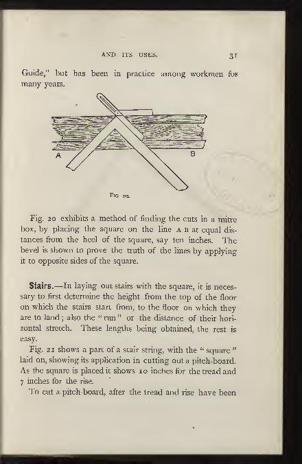
Fig. 20 exhibits a method of finding the cuts in a mitre
box, by placing the square on the line a b at equal dis-
tances fironi the heel of the square, say ten inches. Thebevel is shown to prove the truth of the lines by applying
it to opposite sides of the square.
Stairs.—In laying out stairs with the square, it is neces-
sary to first determine the height from the top of the floor
on which the stairs start from, to the floor on which they
are to land ; also the " run " or the distance of their hori-
zontal stretch. These lengths being obtained, the rest is
easy.
Fig. 2 1 shows a part of a stair string, with the " square "
laid on, showing its application in cutting out a pitch-board.
As the square is placed it shows lo inches for the tread and
7 inches for the rise.
To cut a pitch-board, after the tread and rise have been
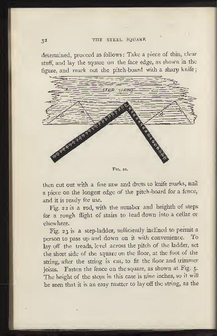
32 THE STEEL SQUAKE
determined, proceed as follows : Take a piece of thin, clear
stuff, and lay the square on the face edge, as shown in the
figure, and mark out the pitch-board with a sharp knife
;
Fig. 21.
then cut out with a fine saw and dress to knife marks, nail
a piece on the longest edge of the pitch-board for a fence,
and it is ready for use.
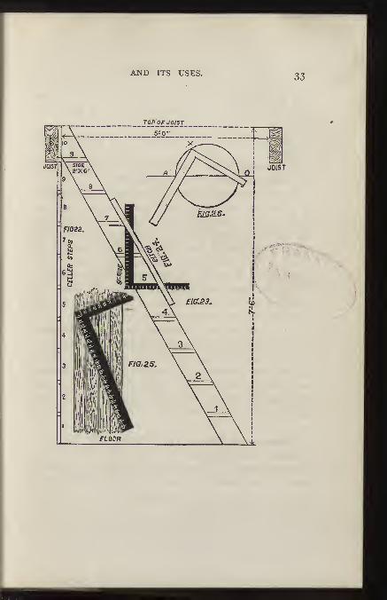
Fig. 2 2 is a rod, with the number and heighth of steps
for a rough flight of stairs to lead down into a cellar or
elsewhere.
Fig. 23 is a step-ladder, sufficiently inclined to permit a
person to pass up and down on it with convenience. To
lay off the treads, level across the pitch of the ladder, set
the short side of the square on the floor, at the foot of the
string, after the string is cut, to fit the floor and trimmer
joists. Fasten the fence on the square, as shown at Fig. 5.
The height of the steps in this case is nine inches, so it will
be seen that it is an easy matter to lay off the string, as the
34 THE STEEL SQUARE
long side of the square hangs plumb, and nine inches up
its length will be the distance from one step to the next
one.
Fig. 24 shows the square and fence in position on the
string.
The opening in the floor at the top of the string shows
the ends of trimming joists, five feet apart.
Fig. 25 shows how to divide a board into an even number
of parts, each part being equal, when the same is an un-
even number of inches, or parts of an inch in width. Lay
the square as shown, with the ends of the square on the
edges of the board, then the points of division will be
found at 6, 12, and 18, for dividing the board in four
equal parts; or at 4, 8, 12, 16, and 20, if it is desired to
divide the board into six equal parts. Of course, the
common two-foot rule will answer this purpose as well
as the square, but it is not always convenient.
Fig. 26 shows how a circle can be described by means
of a " steel square " without having recourse to its centre.
At the extremities of the diameter, a, o, fix two pins, as
shown ; then by sliding the sides of the square in contact
with the pins, and holding a pencil at the point x, a semi-
circle will be struck. Reverse the square, repeat the pro-
cess, and the circle is complete.
Miscellaneous Rules.—^The following rules have been
tested over and over again by the writer, and found reliable
in every instance. They have been known to advanced
workmen for many years, but were never pubhshed, so far
as the writer knows, until they appeared in the American
Builder, some years ago
:

AND ITS USES. 35
Measurement.—Let us suppose that we have a pile of
lumber to measure, the boards being of different widths, and
say 1 6 feet long. We take our square and a bevel with a
long blade and proceed as follows : First we set the bevel
at 1 2 inches on the tongue of the square, because we want
to find the contents of the board in feet, 12 inches being
one foot ; now we set the other end of the bevel blade on the
16 inch mark on the blade of the square, because the boards
are 16 feet long. Now, it must be quite evident to any
one who would think for a moment, that a board 1 2 inches,
or one foot wide, and 16 feet long, must contain 16 feet of
lumber. Very well, then we have 16, the length, on the
blade. Now, we have a board 1 1 inches wide, we just
move our bevel from the 12 inch mark to the 11 inch mark,
and look on the blade of the square for the true answer
;
and so on with any width, so long as the stuff is 16 feet
long. If the stuff is 2 inches thick, double the answer, if
3 inches thick, treble the answer, etc.
Now, if we have stuff 14 feet long, we simply change
the bevel blade from 16 inches on the square blade, to 14
inches, keeping the other end of the bevel on the 12 inch
mark, 1 2 inches being the constant figure on that side of
the square, and it will easily be seen that any length of
stuff within the range of the square can be measured ac-
curately by this method.
If we want to find out how many yards of plastering or
painting there are in a wall, it can be done by this method
quite easily. Let us suppose a wall to be 12 feet high and
18 feet long, and we want to find out how many yards of
plastering or painting there are in it, we set the bevel on
the 9 inch mark on the tongue (we take 9 inches because 9

36 THE STEEL SQUARE
square feet make one square yard,) we take i8 inches, oneof the dimensions of the wall, on the blade of the square;then after screwing the bevel tight, we slide it from 9 inchesto 12 inches, the latter number being the other dimension,and the answer will be found on the blade of the square.
It must be understood that 9 inches must be a constantfigure when you want the answer to be in yards, and in
measuring for plastering it is as well to set the other end ofthe bevel on the figure that corresponds with the height ofthe ceiling, and then there will require no movement ofthe bevel further than to place it on the third dimension.This last rule is a very simple and very useful one ; of course" openings " will have to be allowed for, as this rule gives
the whole measurement.
If the diagonal of any parallelogram within the range ofthe square is required, it can be obtained as follows : Set the
blade of the bevel on 8^ in. on the tongue of the square,
and at 1 2^ in. on the blade;securely fasten the bevel at this
angle. Now, suppose the parallelogram or square to be 11
inches on the side, then move the bevel to the 1 1 inch markon the tongue of the square, and the answer, 159-16, will befound on the blade. All problems of this nature can be solved
with the square and bevel as the latter is now set. Thereis no particular reason for using 8^ and 12^, only that
they are in exact proportion to 70 and 99. 4^ and 6
3-16 would do just as well, but would not admit as readyan adjustment of the bevel.
To find the circumference of a circle with the square andbevel proceed as follows : Set the bevel to 7 on the tongueand 22 on the blade ; move the bevel to the given diameteron the tongue of the square, and the approximate answer
AND ITS USES. 37
will be found on the blade. When the circumference is
wanted the operation is simply reversed, that is, we put
the bevel on the blade and look on the tongue of the square
for the answer.
If we want to find the side of the greatest square that
can be inscribed in a given circle, when the diameter is
given, we set the bevel to 8^ on the tongue and 12 on the
blade. Then set the bevel of the diameter, on the blade,
and the answer will be found on the tongue.
The circumference of an ellipse or oval is found by set-
ting 5^ inches on the tongue and 8^ inches on the blade
;
then set the bevel to the sum of the longest and shortest
diameters on the tongue, and the blade gives tlje answer.
To find a square of equal area to a given circle, we set the
bevel to 9^ inches on the tongue, and 1 1 inches on the blade
;
then move the bevel to the diameter of the circle on the
blade, and the answer will be found on the tongue./ If the
circumference of the circle is given, and we want to find a.^*^'
square containing the same area, we set the bevel to 5^inches on the tongue and 19^ inches on the blade.
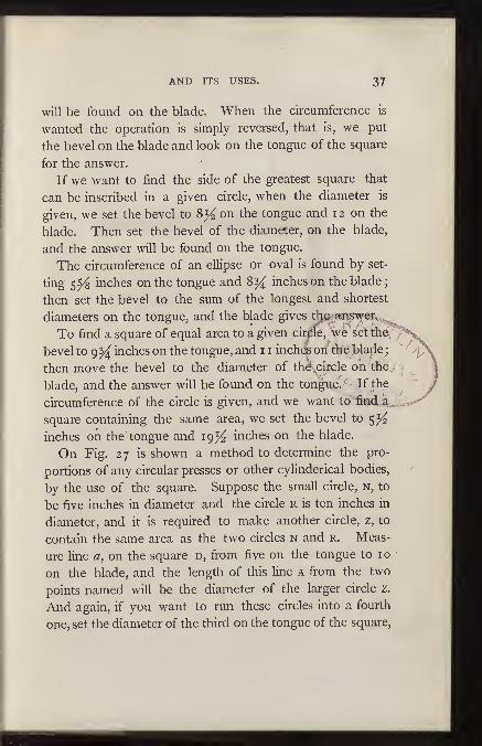
On Fig. 27 is shown a method to determine the pro-
portions of any circular presses or other cylinderical bodies,
by the use of the square. Suppose the small circle, n, to
be five inches in diameter and the circle r is ten inches in
diameter, and it is required to make another circle, z, to
contain the same area as the two circles n and r. Meas-
ure line a, on the square d, from five on the tongue to 10
on the blade, and the length of this line a from the two
points named will be the diameter of the larger circle z.
And again, if you want to run these circles into a fourth
one, set the diameter of the third on the tongue of the square,
38 THE STEEL SQUARE
and the diameter of z on the blade, and the diagonal
will give the diameter of the fourth or largest circle, and the
same rule may be carried out to infinite extent. The rule
is reversed by taking the diameter of the greater circle andlaying diagonally on the square, and letting the ends touch
whatever points on the outside edge of the square. Thesepoints will give the diameter of two circles, which com-bined, will contain the same area as the larger circle. Thesame rule can also be applied to squares, cubes, triangles,
rectangles, and all other regular figures, by taking* similar
dimensions only; that is, if the largest side of one triangle
is taken, the largest side of the other must also be taken,
and the result will be the largest side of the required tri-
angle, and so with the shortest side.
In Fig. 28 we show how the centre of a circle may be de-termined without the use of compasses ; this is based onthe principle that a circle can be drawn through any threepoints that are not actually in a straight line. Suppose wetake A B c D for four given points, then draw a line from a
T
Fig. 27.

AND ITS USES. 39
to D, and from b to c;get the centre of these Hnes, and
square from these centres as shown, and when the square
crosses, the line, or where the lines intersect, as at x, there
will be the centre of the circle. This is a very useful rule, and
Fig. 28.
by keeping it in mind the mechanic may very frequently
save himself much trouble, as it often happens that it is ne-
cessary to find the centre of the circle, when the compasses
are not at hand.
In Fig. 29 we show how the square can be used, in lieu
of the trammel, for the production of ellipses. Here the
square, e d f, is used to form the elliptical quadrant,
A B, instead of the cross of the trammel \ h I k may be
simply pins, which can be pressed against the sides of the
square while the tracer is moved. In this case the adjust-
ment is obtained by making the distance, h /, equal to the
semi-axis minor, and the distance / k, equal to the semi-axis
major.
40 THE STEEL SQUARE
Fig. 29.
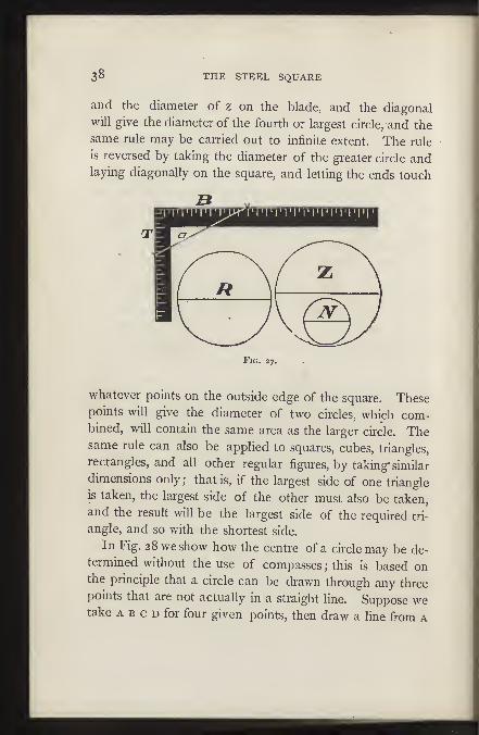
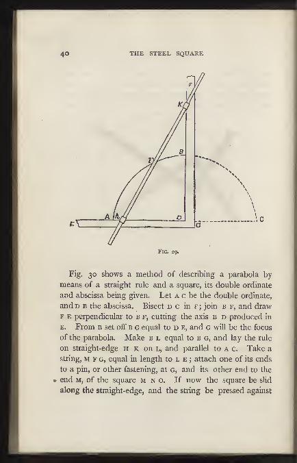
Fig, 30 shows a method of describing a parabola by-
means of a straight rule and a square, its double ordinate
and abscissa being given. Let a c be the double ordinate,
andD B the abscissa. Bisect d c in f; join b f, and draw
F E perpendicular to b f, cutting the axis b d produced in
E. From B set off b g equal to d e, and g will be the focus
of the parabola. Make b l equal to b g, and lay the rule
on straight-edge h k on l, and parallel to a c. Take a
string, M F G, equal in length to l e ; attach one of its ends
to a pin, or other fastening, at g, and its other end to the
• end M, of the square m n o. If now the square be slid
along the straight-edge, and the string be pressed against
The two arms of a horizontal lever are respectively
9 inches and 13 inches in length from the suspending
point; a weight of 10 lbs. is suspended from the shorter
arm, and it is required to know what weight wUl be re-
quired to suspend on the long arm to make it balance.
Set a bevel on the blade of square at 13 inches and the
other end of the bevel on the 9 inch mark on tongue of
square, then sHde the bevel from 13 inches to 10 on the
blade of square, and the answer will be found on the
tongue of the square. It is easy to see how this rule can
be reversed so that a weight required for the shorter arm
can be found.
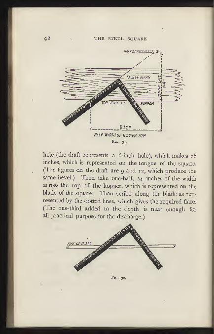
Fig. 3 1 shows how to get the flare for a hopper 4 feet
across the top and 1 6 inches perpendicular depth. Add to
the depth one-third of the required size of the discharge
42 THE STEEL SQUARE
HALFOFDISCmce^ 3"j
HALF W/IDTH OF HOPPER TOPFig. 31.
hole (the draft represents a 6-mch hole), which makes 18
inches, which is represented on the tongue of the square.
(The figures on the draft are 9 and 12, which produce the
same bevel.) Then take one-half, 24 inches of the widthacross the top of the hopper, which is represented on the
blade of the square. Than scribe along the blade as rep-
resented by the dotted lines, which gives the required flare.
(The one-third added to the depth is near enough for
all practical purpose for the discharge.)
Fig. 32.

AND ITS USES. 43
Fig. 32 shows how to apply the square to the edge of
a board in order to obtain the bevel to form the joint.
Using the same figures as in Fig. 31, scribe across the edge
of the board by the side of the tongue, as shown by dotted
lines. The long point being the outside.
14- ^
/ //XN
Fig. 33.
On Fig. 33 we show a quick method of finding the
centre of a circle: Let n n, the corner of the square, touch
the circumference,. and where the blade and tongue cross
it will be divided equally ; then move the square to anyother place and mark in the same way and straight edge
across, and where the line crosses a, b, as at o, there will
be the centre of the circle.
44 THE STEEL SQUARE
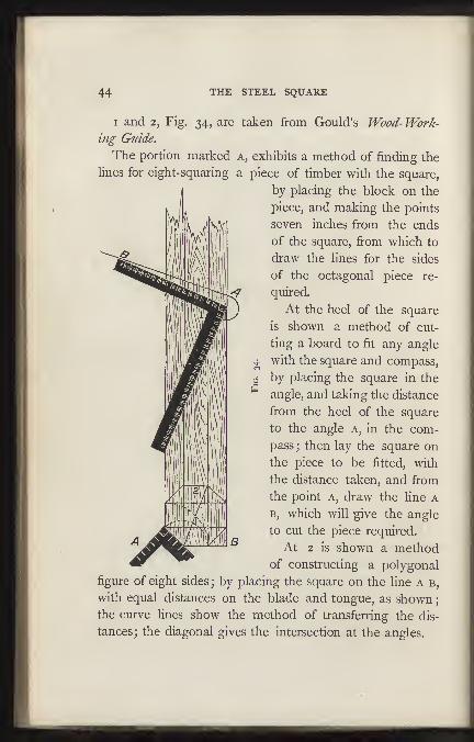
I and 2, Fig. 34, are taken from Gould's Wood- Work-
ing Guide.
The portion marked a, exhibits a method of finding the
lines for eight-squaring a piece of timber with the square,
by placing the block on the
piece, and making the points
seven inches from the ends
of the square, from which to
draw the lines for the sides
of the octagonal piece re-
quired.
At the heel of the square
is shown a method of cut-
ting a board to fit any angle
^ with the square and compass,
j by placing the square in the
" angle, and taking the distance
from the heel of the square
to the angle a, in the com-
pass ; then lay the square on
the piece to be fitted, with
the distance taken, and from
the point a, draw the line a
B, which will give the angle
to cut the piece required.
At 2 is shown a methodof constructing a polygonal
figure of eight sides;by placing the square on the line a b,
with equal distances on the blade and tongue, as shown
;
the curve lines show the method of transferring the dis-
tances; the diagonal gives the intersection at the angles.
AND ITS USES. 45
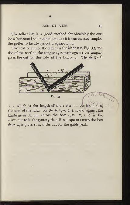
The following is a good method for obtaining the cuts
for a horizontal and raking cornice ; it is correct and simple
;
the gutter to be always cut a square mitre.
The seat or run of the rafter on the blade r c, Fig. 35, the
rise of the roof on the tongue a, c, mark against the tongue,
gives the cut for the side of the box a, c. The diagonal
Fig. 35.
A, R, which is the length of the rafter on th^ bl^de a, d,
the seat of the rafter on the tongue d s, mark kgaipst the
blade gives the cut across the box a, d. d, a, c is the
mitre cut to fit the gutter ; then if we square across the box
from A, it gives f, a, c the cut for the gable peak.

4^ THE STEEL SQUARE
PART II.
The following useful applications of the square werekindly furnished for this work, by Mr. Croker; several ofthem are new and original
:
Consider the blade of the square as representing thespaji of a building, but without any reference to actual orscale measurement. Next, some particular portion of theblade is to be taken as the rise of the supposed if
a third, fourth, or half pitch is required, then a third,
fourth, or a half of the blade is conceived as the rise whichwith half the blade solves the pitch. From this it will beseen that half the blade is always taken as the base of thetheoretical co?nmon rafter. Where we have to deal withirregular pitches—by which is meant those pitches whichare not a quarter, sixth, third, half, etc., of the building-then the square is to be applied to the irregular pitchwith the blade lying in the direction of the pitch andthe centre of the blade at the intersection of pitch andbase line of the common rafter, and the resulting distance
on the tongue, where it intersects the base line, is thedistance to be taken as the rise of the theoretical rafter.
Let us now take a hip-roof over a square plan (for all therules apply only to square planned building), and the prac-tical problems supposed to need solution are : Length ofcommon rafters, the plumb and level cuts
;length of hip-
rafter, its plumb and level cuts ; bevel of jacks and sheet-
AND ITS USES. 47
ing boards against the hips ;" backing " of the hip-rafter,
top and down bevel of a purlin mitering against the hip
with its surface in line with the plane of the roof. If the
student can readily and inteUigently solve these problems,
he will be in a position to make extensions in the principles
involved. Let the width of building under consideration
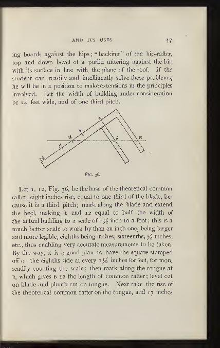
be 24 feet wide, and of one third pitch.
Fig. 36.
Let I, 12, Fig. 36, be the base of the theoretical common
rafter, eight inches rise, equal to one third of the blade, be-
cause it is a third pitch; mark along the blade and extend
the heel, making it and 12 equal to half the width of
the actual building to a scale of inch to a foot; this is a
much better scale to work by than an inch one, being larger
and more legible, eighths being inches, sixteenths, ^ inches,
etc., thus enabling very accurate measurements to be taken.
By the way, it is a good plan to have the square stamped
off" on the eighths side at every i y^, inches for feet, for more
readily counting the scale ; then mark along the tongue at
B, which gives b 1 2 the length of common rafter ; level cut
on blade and plumb cut on tongue. Next take the rise of
the theoretical common rafter on the tongue, and 1 7 inches

48 THE STEEL SQUARE
on the blade, as the theoretical base of the hip-rafter;
place the square as shown at Fig. 37 ; then multiply the
^^i? ^ ^I
^n^- r-
Fig. 37.
actual base of common rafter 12, (Fig. 36.) by 1*414 =i6'968 feet, or 17 feet, practically, which set off on blade at a
1 7 ; mark on tongue at b, then B 1 7 is the length of hip-
rafter. For the bevels of jacks and sheeting-boards against
hips take the diagonal b 12—theoretical rafter—Fig. 36, on
the blade with half the blade—the theoretical base—and
place the square as shown at Fig. 38, then mark along the
blade for bevel of jacks, and along tongue for bevel of
sheeting-boards.
Fig. 38.

AND ITS USES. 49
For the " backing " of hip, take the diagonal of the
theoretical hip-rafter, 8, 17 (Fig 37), on the blade, and its
rise—8 inches—on the tongue, and place square as shown
at Fig. 39 ; mark by the tongue which gives the bevel re-
FiG. 39.
quired. To get the upper bevel of a purlin lying in
the plane of the roof, take the bevei at tongue (Fig. 38),
for the down bevel take the blade distance 147— 16 (Fig.
38) on the blade with the theoretical rise—8;place the
square as shown at Fig. 40 ; mark by the tongue which
gives the bevel required.
Fig. 40.
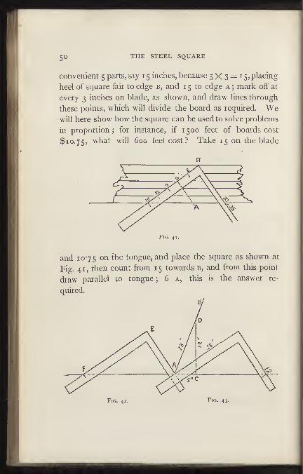
Fig. 41 shows how any length or breadth within the extent
of the blade of the square can be instantly divided into any
equal parts. Let a and b represent the edges of a board, say
8^ inches, wide, to be divided into 5 equal parts; take any
5° THE STEEL SQUARE
convenient 5 parts, say 1 5 inches, because 5X3= 15, placing
heel of square fair to edge b, and 1 5 to edge a ; mark off" at
every 3 inches on blade, as shown, and draw lines through
these points, which will divide the board as required. Wewill here show how the square can be used to solve problems
in proportion; for instance, if 1500 feet of boards cost
$10.75, what will 600 feet cost ? Take 15 on the blade
B
Fig. 41.
and 1075 on the tongue, and place the square as shown at
Fig. 41, then count from 15 towards b, and from this point
draw parallel to tongue ; 6 a, this is the answer re-
quired.
Fig. 42. Fig. 43.

AND ITS USES. 51
Figs. 42 and 43 show quite a novel and useful way of
bisecting any angle. Let a i 2, a b be the given sides of an
acute angle to be bisected. At any convenient point as c
square c D from c 12. Now take c d on the tongue, and
the sum of a d and a c on the blade of the square, place
as shown in the Figure, then mark by the blade, which is
the bisection required. If the angle is obtuse, as a b, a f,
(Fig. 42), produce a convenient distance, as a c, square
over c D, take c d on the tongue, and the sum of a d, a c,
on the blade, place square as shown, and mark by the
tongue for the required bisection.
Fig. 44.
Fig. 44 shows a handy way of finding the bevel of rails
to diminish door stiles. Place the square fair with the
known joint a b, mark by the tongue, then the resulting
bevel at a is the same as that at b.

52 THE STEEL SQUARE
PART III.
The following rules have been gathered from various
sources, chiefly, however, from jDapers recently published in
the Scientific American Supplement, by John O. Connell, of
St. Louis, and from papers contributed to the Builder a?id
Wood- Worker, by Wm. E. Hill, of Terre Haute, Ind.
Fig. 45.
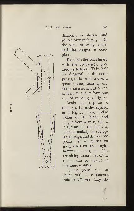
* Fig. 45 shows how an octagon can be produced by the
aid of a steel square. Prick off the distance a o equal to
half the distance of the square ; mark this distance on the
blade of the square from b to o, place the square on the
*Win. E. HUL
AND ITS USES. 53
diagonal, as shown, and
square over each way. Dothe same at every angle,
and the octagon is com-
plete.
To obtain the same figure
with the compasses, pro-
ceed as follows : Take half
the diagonal on the com-
passes, make a little over a
quarter sweep from c, and
at the insersection at D and
c, then D and c form one
side of an octagonal figure.
Again: take a piece of
timber twelve inches square,
as at Fig. 46 ; take twelve
inches on the blade and
tongue from a to b, and a
to c, mark at the point A,
operate similarly on the op-
posite edge, and the marked
points will be guides for
guage-lines for the angles
forming an octagon. The
remaining three sides of the
timber can be treated in
the same manner.
These points can be
found with a carpenter's
rule as ioUows: Lay the
4

54 THE STEEL SQUARE
rule on the timber, partly opened, as shown, in the cut,
"prick off" at the figures 7 and 17 as at a and b, andthese points will be the guides for the gauge-lines. I'hesame points can be found by laying the square diagonallyacross the timber and " pricking " off 7 and 17.
To make a moulder's flask octagonal proceed as follows :
The flask to be four feet across. Multiply 4 X 5 (as anoctagon is always as 5 to 12 nearly), which gives 20; di-
vide by 12, which gives feet, cut mitre to suit this
measurement, nail into corners of square box, and you havean octagon flask at once.
Another method of constructing an octagon is shown at
Fig. 47. Take the side 2& a b for a radius, describe an arc
cutting the diagonal at d\ square over from d to e, andthe point e will then be the gauge-guide for all the sides.

AND ITS USES. 55
Another method (Fig. 48) is to draw a straight hne, c
b, any length; then let a b and a c corresponding
figures on the blade and tongue of the square, mark along
either and measure the distance of required octagon ; move
Fig. 48.
the square and mark also. Now use the square the
same as before, and the marks c b and b d are the points
required.
Fig. 49 shows the application of a long bevel to a
square, by which some calculations can be made with
greater ease and quickness than by the usual arithmetical
process. The largest size of carpenter's bevel placed under
the framing square will answer in nearly every case. One
edge of each blade should be perfectly straight and the
edge of L should be cut out in several places to see the
blade e, when placed under the square. The two blades
should be fastened together by a thumb-screw. There

56 THE STEEL SQUARE
should be three holes in l, one near each end and one in
the middle, and a notch filed by each hole, so that the
blade e, may be shifted when necessary.
Fig. 49
*To Find the Diagonal of a Square by this instrument, set
the blade e to 8^ inches on the tongue and 12^ inches
on the blade. Then screw the bevel fast ; and supposing
the side of the square in question is 1 1 inches, move blade
E to the II inch mark on the tongue, keeping blade l
against the square, when blade e will touch 15 9-16 inches
on the blade, which is the required diagonal. There is nospecial reason for using 8^ and i2}i; other numbers maybe employed provided the proportion of 70 to 99 exists
between them. In the problem just solved as in all that
follow, the bevel being once set to solve a particular ques-
*J. O. Connell.
AND ITS USES. 57
tion will solve all the others of the same kind, till the bevel
is altered.
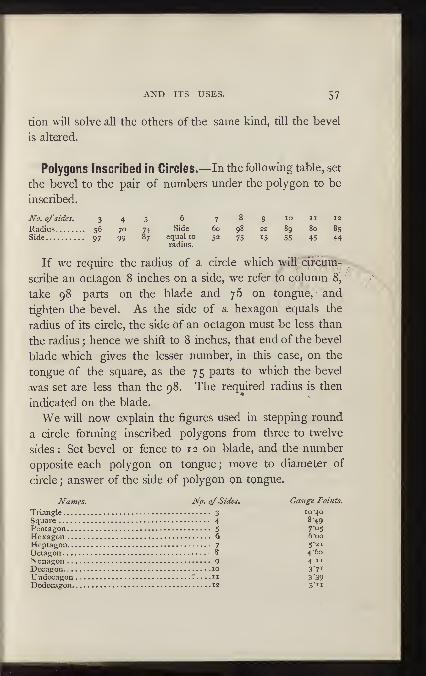
Polygons Inscribed in Circles.—In the following table, set
the bevel to the pair of numbers under the polygon to be
inscribed.
No. ofsides. 3 4 5 6 7 8 9 lo ii 12
Radius 56 70 74 Side 60 98 22 89 80 85Side 97 99 87 equal to 52 75 15 55 45 44
radius.
If we require the radiu§ of a circle which will circum-
scribe an octagon 8 inches on a side, we refer to column 8,
take 98 parts on the blade and 76 on tongue, - and
tighten the bevel. As the side of a hexagon equals the
radius of its circle, the side of an octagon must be less than
the radius ; hence we shift to 8 inches, that end of the bevel
blade which gives the lesser number, in this case, on the
tongue of the square, as the 75 parts to which the bevel
was set are less than the 98. The required radius is then
indicated on the blade.
We will now explain the figures used in stepping round
a circle forming inscribed polygons from three to twelve
sides : Set bevel or fence to 1 2 on blade, and the number
opposite each polygon on tongue ; move to diameter of
circle ; answer of the side of polygon on tongue.
Names. No. ofSides. Gauge Points.
Triangle
3
lo'^o
Square
4
8'49
Pentagon
5
7'°SHexagon 6 6"oo
Heptagon
7
5'2i
Octagon
8
4 '60
i^onagon 9 4"Decagon 10 371Undecagon n 3 '39
Dodecagon 12 3'ii

58 THE STEEL SQUARE
To divide a circle into a given number of parts, multiplythe corresponding number in column one and the productis the chord to lay off on circumference. The side of apolygon is known, to find the radius of a circle that will
circumscribe:Multiply the given side by the correspond-
ing number opposite of polygon in column two.
No. o_f ^ 7igle ofSides. Name ofPolygon. Angle. Polygon. Column 1. Columns3 Triangle 120 60 1-732 -5,7,4 Square 90 90 r-^t^
IPentagon 72 108 1-77^
^ Hexagon 60 120 Radius. Side.7 Heptagon 513.7 ,384-7 8677 i-.S2
IO'^t^g""
45 135 7653 1-30719 Nonagon 40 ,40 440 1-4863o Decagon 36 144 .e/go i-6i8iII Undecagon 328-11 1473-" -5634 1-77,4Dodecagon 30 15^' .^5,^6
,.775+
The side of a polygon is known, to find the length ofperpendicular
: Set bevel or fence to the tabulated numbersbelow. Example: The side of an octagon is 12, set bevelto 23 on tongue, 27 11-16 on blade. Blade gives theanswer.
No. of Sides. 34567 8 9 10 II 12
^EZ%^f^'-- 9 '3° 13 273-4 277.10 503-4 281-2 313-4 26Side of Polygon 31 i-s 2 351.4 15 26 23 37^* iS 1-2 301-2 14
To Inscribe three Equal Circles in a circle of given diame-ter. Set to 61^ on tongue and 14 on blade. Move the bevelto the given diameter on the blade and the requireddiameter appears on the tongue.
Four equal circles require a bevel of 2-91 and 14.
The following also, is another use for the square andbevel combined.
If a person is drawing a machine on a scale of 1 inchto the foot, he may simply lay a common rule under the

AND ITS USES. 59
square, touching the 1 2 inch mark on the blade, and the
ii^ inch mark on the tongue; he then possesses a con-
trivance by which he may easily reduce from one scale to
the other. For instance, if a piece of stick 2 3^ inches
square is to go into the construction, the draughtsman finds
the g}( inch mark on the blade, that is 2^ inches back
from the 12 inch mark, and measures square out to the
rule. This distance is the reduced section of the stick.
A straight mark, drawn on a table or a drawing board,
serves as well as a rule.
Conveyors' shaft 5 inches in diameter, 12 feet long, pitch
of flights 9 inches ; make a posteboard template;multiply-
ing the diameter by 3-1416 gives the base, and the 9 is the
altitude. The paper would be 9 inches altitude, 15 71-100
base ; draw a line along shaft, place altitude or 9 inches along
this line, scribe along the hypothenuse ; this gives the spiral
course of flight. This principle also teaches how to cut round
sticks of straight timber by marking along base of template,
take square on each end the same as taking a stick out of
wind, before striking lines.
The cuts for the edges of the pieces of a hexagonal hop-
per are found by subtracting the width of one piece at the
bottom, viz.,. the width of same at top, and taking the re-
mainder on the tongue, and depth of side on blade. The
tongue gives the cut. For the cut on the face of the sides,
take 7-12 of the rise on the tongue, and the depth of side
on the blade. The tongue gives the cut. The bevel for
the top and bottom edges is found by taking the rise on
the blade, and the run on the tongue ; the latter gives the
;'*Jc'"fii\(i'l1iexu': :6'* a^ octagon;.! licpiic-- for: the face of
6o THE STEEL SQUARE
the- board and also the edge, substract the rise from the
width of side ; take the remainder on the tongue and widthof side on blade ; the tongue gives the cut. The edge of
the stuff is to be square when applying the bevel. Thebevel for the top and bottom edges of the sides is found bytaking the rise on the blade, and run on the tongue, the
latter gives the cut. This makes the edges horizonatal.
The edges are not to be beveled till the four sides are
cut.
To lay off Angles of 60° and 30°.—Mark any number ofinches, say 14, on an indefinite line. Place the blade
against one extremity of this distance, and the 7 inch markof the tongue at the other. The tongue then forms anangle of 60° with the indefinite line, and the blade an angle
of 30°.
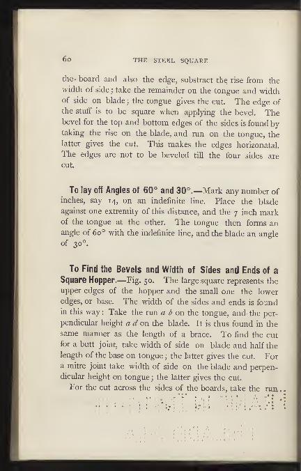
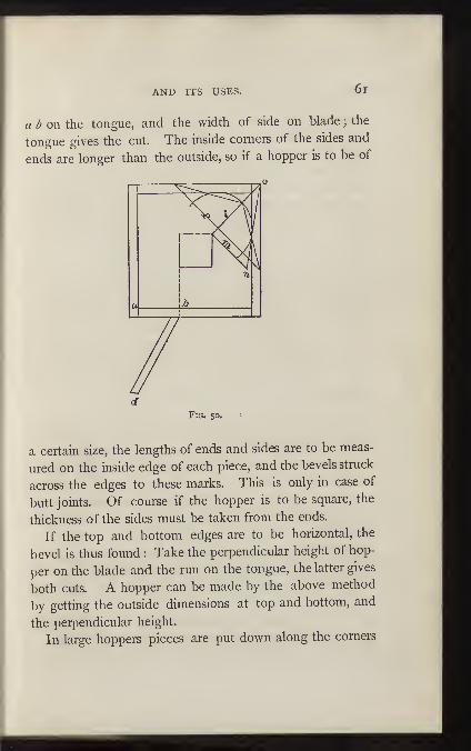
To Find the Bevels and Width of Sides and Ends of aSquare Hopper.—Fig. 50. The large square represents the
upper edges of the hopper and the small one the lower
edges, or base. The width of the sides and ends is foundin this way : Take the run a d on the tongue, and the per-
pendicular height a d on the blade. It is thus found in the
same manner as the length of a brace. To find the cut
for a butt joint, take width of side on blade and half the
length of the base on tongue ; the latter gives the cut. Fora mitre joint take width of side on the blade and perpen-
dicular height on tongue ; the latter gives the cut.
For the cut across the sides of the boards, take the run
.
AND ITS USES. 6i
a b on the tongue, and the width of side on blade ;the
tongue gives the cut. The inside corners of the sides and
ends are longer than the outside, so if a hopper is to be of
dFig. so.
a certain size, the lengths of ends and sides are to be meas-
ured on the inside edge of each piece, and the bevels struck
across the edges to these marks. This is only in case of
butt joints. Of course if the hopper is to be square, the
thickness of the sides must be taken from the ends.
If the top and bottom edges are to be horizontal, the
bevel is thus found : Take the perpendicular height of hop-
per on the blade and the run on the tongue, the latter gives
both cuts. A hopper can be made by the above method
by getting the outside dimensions at top and bottom, and
the perpendicular height.
In large hoppers pieces are put down along the corners
62 THE STEEL SQUARE
to Strengthen them. The length, and the bevel to fit the
corner are thus found : Suppose the top of hopper is 8 feet,
and the bottom i8 inches square. Find the diagonals of
each, subtract the one from the other, and half the re-
mainder is the run for the comer piece. From the length ofthis run, /, and the rise, a b, we find the length of the corner
piece. To find the bevel or backing, take on the blade thelength of the corner piece and on the tongue the rise ; the
latter gives the bevel. Another method is to draw the line,
/, to represent the seat of the corner piece, set off squarewith this the line m, of the same length as the run, a b.
Then draw n o, which is the length of the corner piece. Tofind the backing, draw a line, /, anywhere across /, at right
angles therewith, and at its intersection with line, /, strike
a circle tangent to ;z o. From the point of intersection ofthe circle with /, draw lines to the extremities of Theangle made by these lines is the bevel or backing.
Another method generally employed for finding the
bevels of hoppers is to bevel the top and bottom edges ofthe sides and ends to the angle they are to stand at, then to
lay a bevel set to a mitre, or angle of 45°, on the bevelededge, and that will lay off a mitre joint, while a try-square
will lay off a butt joint. An angle of 45° will mitre onlythose boxes with sides which are vertical and square witheach other.
When the sides and ends of a rectangular box or hopperare of the same width, that is, when sides and ends slope
at equal angles, the bevels, either butt or mitre, are foundas for square hoppers.
When a hopper has the sides and ends of different
widths, that is, when sides and ends stand at different angles.

AND ITS USES.
both having the same rise, find the cuts for each from its
respective rise, run and width.
Roofing.—Fig. 51. A hip-roof with two corners out of
square is given an example, the dimensions of which are
:
width 15 feet, rise of roof 5 feet, length 30 feet on the
Fig. 51.
shorter side, 33 feet on the longer. The timbers a d, c d,
E G, E G, are the hip rafters ; j j the jack rafters. The seats
of each hip rafter should form a square, so that each pair
of jack rafters, j j, for instance, may be cut of equal length.
Lengths and Bevels of Hip-Rafters.—We will first con-
sider those on the square end of the roof. In order to find
their length, it is first necessary to obtain their run, which
is found as follows : Take half the width of building on both
blade and tongue, whence is obtained the length of seat
from G to E, at the intersection of the dotted lines. By similar
use of the square, this length with the rise of roof, gives
the length of the hip-rafter. The lengths of all the rafters

€4 THE STEEL SQUARE
should be measured along the middle, as the dotted lines
show. This is the full length; half the thickness of the
ridge-pole is to be taken off, measured square back from
the bevel.
The bevel of the upper end of a hip-rafter is called the
down bevel. It is always square with the lower end bevel,
hence these bevels are found by the parts taken on the
square to find the lengths of the hip-rafters. Another
method is to take 1 7 inches on the blade and the numberof inches of rise to the foot, that is, the rise in inches di-
vided by half the width of roof in feet—on the tongue., The
tongue gives the down bevel, the blade the lower end bevel.
The reason for the foregoing is that when the hip-rafters are
square with each other, the seat of the hip is the diagonal
of a square whose side is half the width of building. Thediagonal of a square with a 1 2 inch side is 1 7 inches nearly.
So if the rise of roof in -i foot is 6 inches, the rise of hip-
rafter will be that only in 17 inches. The directions here
given assume that the hip-rafter abuts the ridge-pole at right
angles, but as the ground plan of the roof shows that they
meet at an acute angle, another bevel must be considered,
called the side bevel ofthe hip-rafters. Were there no slope
to the roof, the bevel where they meet the ridge pole wouldbe an angle of 45°, as the hips would be square with each
other. When a pitch or slope is given, the hips depart from
the right angle, and therefore the side bevels are always
less than 45°. Take the length of hip on the blade, andits run on the tongue ; the blade gives the cut.
Backing of the hip-rafters. The backs of the hip-rafters
must be beveled to lie even with the planes of the roof.
This bevel must slope from the middle toward either side.
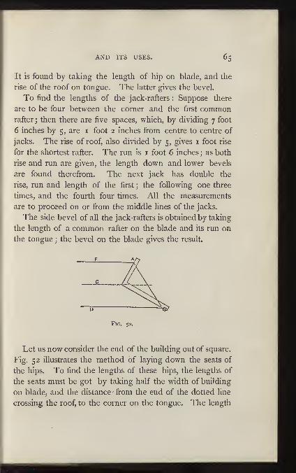
AND ITS USES, 65
It is found by taking the length of hip on blade, and the
rise of the roof on tongue. The latter gives the bevel.
To find the lengths of the jack-rafters : Suppose there
are to be four between the corner and the first commonrafter; then there are five spaces, which, by dividing 7 foot
6 inches by 5, are i foot 2 inches from centre to centre of
jacks. The rise of roof, also divided by 5, gives i foot rise
for the shortest rafter. The run is i foot 6 inches ; as both
rise and run are given, the length down and lower bevels
are found therefrom. The next jack has double the
rise, run and length of the first ; the following one three
times, and the fourth four times. All the measurements
are to proceed on or from the middle lines of the jacks.
The side bevel of all the jack-rafters is obtained by taking
the length of a common rafter on the blade and its run on
the tongue ; the bevel on the blade gives the result.
Fig. 52.
Let us now consider the end of the building out of square.
Fig. 52 illustrates the method of laying down the seats of
the hips. To find the lengths of these hips, the lengths of
the seats must be got by taking half the width of building
on blade, and the distance from the end of the dotted line
crossing the roof, to the corner on the tongue. The length
66 THE STEEL SQUARE
of the seat so obtained taken on the square, with the rise of
the roof, gives the length of the respective hip-rafter.
The down and lower end bevels are found as in the pre-
vious hip-rafters. To obtain each side bevel, add the dis-
tance from the dotted line to the corner and the gain of
the hip-rafter; take the sum on the blade, and half the width
of building on the tongue ; the latter gives the cut.
The lengths, etc., of the jack-rafters on the side, are de-
termined as at the square end of the roof ; the side bevel
being found by taking the length of a common rafter on
the blade, and the distance from the dotted line to corner
on the tongue. The latter showing the bevel.
The lengths of jack-rafters on the end. Assuming there
are to be four jacks between the corner and the centre in-
cluded, half the length of the end of the roof must be di-
vided by 5. One side of the roof being 3 feet longer than
the other, we place 3 feet, on tongue, and 1 5 feet, the width
of building, on the blade, and thus obtain the distance from
corner to corner on the end of the roof. Half this divided
by 5 gives the distance of the jacks apart. The distance
from where the middle Hnes of the hips meet to the middle
point of the end of the roof is also to be divided by 5, the
quotient giving the run of the shortest rafter. The rise is
the same as for the jacks on the square end.
These rules give the full length of rafter, so that when
hips come against a ridge-pole or jacks against a hip, half
the thickness of pole or hip, squared back from their downbevels, must be taken off.
Side bevels of these jacks are obtained by adding the
distance from the dotted line to the corner to the gain of
a common rafter in running that distance; take this on the

AND ITS USES. 67
blade, and half the width of building on the tongue. The
blade gives the bevel.
Trusses.—Fig. 53. a is the straining beam, b the brace,
T the tie beam. Generally the brace has about one-third
the length of tie beam for a run. From the rise and run
find the length and lower end bevel of the brace. After
marking the lower end bevel on the stick, add to it just
what is cut out of the tie beam. The bevel of the upper
end of the brace where it butts against the straining beam
is found in the following manner. Take the length of the
brace, or a proportional part, and mark it on the edge of a
board ; take half the rise of the brace on the tongue, lay it
to one of these marks on the board, and move the blade
till it touches the other mark on board. A line drawn
along the tongue gives the bevel for both brace and strain-
ing beam. The angle made between brace and strain-
ing beam is thus bisected. Lay off the measurements from
the outside of the timbers. Put a bolt where shown, with
a washer under the head to fit the angle of straining
beam and brace.
A
Fig. 53.

68 THE STEEL SQUARE
It will be seen in the foregoing work, that the " Steel
Square " is capable of solving quite a number of useful prob-
lems, but it must not be supposed that all its operations
have been shown in this work. The skilled workman, after
a careful study of the operations herein set forth, will, whenoccasion requires, invent applications of the square that are
not. now suspected ; and it is quite possible that future
editions of this work may contain many of these new dis-
coveries. F. T. H.

CATALOGUEOP
Books and PeriodicalsPUBLISHED AND FOR SALE BY
THE INDUSTRIAL PUBLICATION COMPANY,
14: Dey Street, New York.
^"Any of these Books may be obtainedfrom any Bookseller
or Newsdealer, or will be sent Free by mail to any part of the
United States or Canada ONRECEIPT OFPRICE.'
The Amateur's Handbook of Practical Information,
For the Workshop and the Laboratory. Second Edition.
Greatly Enlarged. Neatly Bound - - 15 cents.
This is a handy little bool?, containing just the information neededby Amateurs in the Worlishop and Laboratory. Directions for
making Alloys, Fusible Metals, Cements, Glues, etc.; and for Solder*ing, Brazing, Lacquering, Bronzing, Staining and Polishing Wood,Tempering Tools, Cutting and "Working Glass, Varnishing, Silvering,
Gilding, Preparing Skins, etc., etc.
The New Edition contains extended directions for preparing Polish-ing Powders, Freezing Mixtures, Colored Lights for tableaux. Solu-tions for rendering ladies' dresses incombustible, etc. There has also
been added a very large number of new and valuable receipts.
Rhymes of Science: Wise and Otherwise.
By O. W. Holmes, Bret Hart, Ingoldsby, Prof. Forbes,
Prof. J. W. McQ, Eankine, Hon. E. W. Eaymond, and
others.
With Illustrations. Cloth, Gilt Title. - 50 cents

Section Cutting.
A Practical Guide to the Preparation and Mounting ol
Sections for the Microscope;Special Prominence being
given to the Subject of Animal Sections.' By Sylvester
Marsh. Reprinted from the London edition. WithIllustrations. 12mo., Cloth, Gilt Title, • 75 cents.
This is undoubtedly the most thorough treatise extant upon sectioi.)
cutting in all its details. The American edition has been greatlyenlarged by valuable explanatory notes, and also by extended direc-tions, illustrated with engravings, for selecting and sharpeningknives and razors.
A Book for Beginners with the iVIioroscope.
Being an abridgment of " Practical Hints on the Selectionand Use of the Microscope." ByJohnPhin. Fully illus-
trated, and neatiy and strongly bound in boards. 30 cts.
This book was prepared for the use of those who, having no know-ledge of the use of the microscope, or, indeed, of any scientific appar-atus, desire simple and practical instruction in the best methods ofmanaging the instrument and preparing objects.
How to Use the Microscope.
A Simple and Practical Book, intended for beginners.
By John Phin, editor of "The American Journal of
Microscopy," Second Edition. Greatly Enlarged, with50 illustrations in the text and 4 full-page engravingsprinted on heavy tint paper. 12mo., Neatly bound in
Cloth, Gilt Title. .... 75 cents.
The IVIicroscope.
By Andrew Eoss. Fully Illustrated. 12mo., Cloth,
Gilt Title. 75 cents.
This is the celebrated article contributed by Andrew Eoss to the"Penny Cyclopedia," and quoted so frequently by writers on theMicroscope. Carpenter and Hogg, in the last editions of their workson the Microscope, and Brooke, in his treatise on Natural Philoso-phy, all refer to this article as the best source for full and clearinformation in regard to the principles upon which the moderrachromatic Microscope is constructed. It should be in the libraryof every person to whom the Microscope is more than a toy. It is
written in simple language, free from abstruse technicalities.
NEW DESiaisrsFOE
Fret or Scroll Sawyers.
MR F T HODGSON, whose admirable series of articles on the USE OF THESCROLL SAW are now in course of publication in the Young Scientist, has pre-
pared for us a series of
SEVENTEEIV I>ESIOIVS,
of which the following is a list
:
No. I.—This shows one side, back, and bottom, of a pen rack. It may be made
of ebony, walnut, or other dark wood.u i j j
No. 2.—Design for inlaying drawer fronts, table tops, box lids, and many other
things. It is a sumach leaf pattern.j r v j a^-
No 3.—Design for a thermometer stand. It may be made of any hard wood or
alabaster. The method of putting together is obvious.
No 4 -This shows a design for a lamp screen. The open part may be covered
with tinted silk, or other suitable material, with some appropriate device worked on
with the needle, or, if preferred, ornaments may be painted on the silk, etc.with^he neemc^or,^J containing visiting cards. Will look best made of white holly.
No' 6 —A placque stand, it may be made of any kind of dark or medium wood.
No 7'—A design for ornaments suitable for a window cornice. It should be
made of black walnut, and overlaid on some light colored hardwood., , „
No 8-A design for a jewel casket. This .will be very pretty made of white holly
and lined with blue velvet. It also looks well made of ebony lined with crimson.
No 0.—Frame. Will look well made of any dark wood.
No. 10.—Frame. Intended to be made in pairs. Looks well made of white holly,
with leaves and flowers painted on wide stile.,
No II.—Horseshoe. Can be made of any kind of wood and used for a pen rack.
When decorated with gold and colors, looks very handsome., , , .
No 12 -Design for a hinge strap. If made of black walnut, and planted on a
white or oaken door, will look well., i-ifT,j a
No i3.-Design for a napkin ring. May be made of any kind of hard wood.
No. 14.—Hinge strap for doors with narrow stiles.
No. 15.—Centre ornament for panel.
No. 16.—Corner ornament for panel.
No. 17.—Key-hole escutcheon.
These designs we have had photo-lithographed and printed on good paper, so that
the outlines are sharp, and the opposite sides of each design symmetrical. Common
designs are printed from coarse wooden blocks, and are rough and unequal, so that
it is often impossible to make good work from them.
The series embraces over forty different pieces, and designs of equal quality cannot
be had for less than five, ten or fifteen cents each. We offer them for twenty-five
cents for the set, which is an average price of only one cent and a halt each.
Mailed to any address on receipt of price.
INDUSTRIAL PUBLICATiON CO.,
14 Dej Street, New York.
THE AMERICAN
Journal of Microscopy.
PROSPECTTJS-SIXTH YEAR-1881The object of the Journal of Microscopy is to diffuse a knowledge of the best
methods of using the Microscope; of all valuable improvements in the instrument andIts accessories; of all new methods of microscopical investigation, and of the mostrecent results of microscopical research. The Journal does not address itself to thosewho have long pursued certain special lines of research, and whose wants can besupplied only by elaborate papers, which, from their thoroughness, are entitled to becalled monographs rather than mere articles. It is intended rather to meet the wantsof those who use the microscope for purposes of general study, medical work classinstruction, and even amusement, and who desire, in addition to the information affordedby text-books, such a knowledge of what others are doing as can be derived only froma penodical. With this object in view, therefore, the publishers propose to make theJournal so simple, practical and trustworthy, that it will prove to the advantageof every one who uses the microscope at all to take it.
ILLUSTRATIONS.—The Journal will be freely illustrated by engravingsrepresenting either objects of natural history or apparatus connected with themicroscope.
TRANSACTIONS OF SOCIETIES.—The American Journal of Micro-scopy is not the organ of any Society, but it gives the proceedings of all Societieswhose officers send us a report. As the Journal is devoted ^vlwlly to Microscopy andis in good form and size for binding, no better medium can be had for preserving thescientific records of any Society. Matters of mere business routine we are frequentlyobliged to omit for want of room. ^
EXCHANGES.—An important feature of the Journal is the exchange column bymeans of which workers indifferent parts of the country are enabled, without expenseexcept for postage, to exchange slides and materials with each other.
'
Published Monthly at $1.00 a year.SPECimEIVS FREE.
Four copies for three dollars. Those who wish to economize in the direction ofpenodicals, would do well to examine our clubbing list.
Foreign Subscribers.—The Journal will be sent, postage paid, to any counti-y inthe Postal Union for $1.24, or 5 shillings sterling per year. English postage stampsAmerican currency or American postage stamps taken in payment. In return for apostal order or draft for £\ 5s., five copies of the Journal will be furnished and mailedto different addresses. Make all drafts and postal orders payable to John Phin.
SaoIs. 'XT'oluxneis.Vol. I is out of print. We are occasionally able to complete volumes which, when
bound, we offer for $1.50. Of Vols. II, III and IV we have a few copies on hand.Price J 1. 50 each.
The JotjRNAL OF Microscopy, from its very nature, is a visitor to the very bestfamilies, and its value as an advertising medium has therefore proved to be muchabove that of average periodicals. A few select advertisements will be inserted at therate of 30 cents per line, nonpariel measure, of which twelve lines make an inch.Address
AMERICAN JOURNAL OF MICROSCOPY,p. O. Box 2852, New Yorlk.
Thirty-seventh Year of Republication!
THELondon Lancet for 1881.i monthly Joarnal of British and Foreign medicine, Physiology,
Surgery, Chemistry, Criticism, Literature and IVews*
EDITED BY
m- Tlie American Edition, as piil)lislied l»y the In-dustrial Publication Co., contains EVEItYTmr¥Grelating- to Medical Matters tliat appears in tlie
original London e<lition.
THE LANCET is the oldest and most Practical Medical Journal
published in the English language, and is the national British organ
of Science in its relations to the human frame.
THE LANCET is edited by a corps of the most distinguished
physicians of the British Metropolis, and numbers among its con-
tributors, the best medical and surgical talent of Europe.
THE LANCET for 1881; will contain over 1200 double-column
pages of closely printed matter, exclusive of the advertising sheets.
The type is clear, and printed on the very best calendered book paper.
Our pages contain nearly twice as much reading matter as any other
monthly medical journal published on this side of the Atlantic. Everyeffort will be made to continue this Work, as it ever has been, the
Standard Journal of Medicine and Surgery.
Illustrated with engravingsby the best artists.
Subscription $5.00 per year. Single Numbers 50 cts. eaoh.
Specimen Copies {our bclection), 25 cents.
For Club Rates, Subscriptions, Advertisements, etc,, address
THE INDUSTRIAL PUBLICATION COMPANY,
14 Dey Street, New York.

THE YOUNG SCIENTIST,A Practical Jonrnal for Amateurs.
ISSUED MONTHLY. Price 50 Cents per year.It is charactbrietic of young Americans that they want to be doing something.
They are not content with merely AMOwwa how things are done, or even withseeing them done; they want to do them themselves. In other words, they wantto experiment. Hence the wonderf"! demand thathas sprcicK up for small toolcbests, turning lathes, scroll saws, <vood carving tools, telegraphs, model steamengines, microscopes and all kinds of apparatus. In nine cases out of ten, how-ever, the young workman finds it difficult to learn how to use his tools or ap-paratus after he has got them. It is true that we have a large number of veryexcellent test-books, but these are not j ust the thing. What is wanted is a liv-
ing teacher. Where a living teacher cannot be found, the next best thing is alive journal, and this we propose to furnish. And in attempting this it is notour intention to confine ourselves to mere practical directions. In these daysof knowledge and scientific culture, the " Why " becomes aa necessary as the"How." Theobjectof the Young Scientist is to give clear and easily followeddirections for performing chemical, mechanical and other operations, as well assimple and accurate explanations of the principles involved in the variousmechanical asd chemical processes which we shall undertake to describe.The scope and character of the journal will be better understood from an in-
spection of a few numbers, or from the list of contents found on a subsequentpage, than from any labored description. There are, however, three features towhich we would csil special attention:
OoBBESPONDENCE.—In this department we intend to place our readers in com-munication with each other, and in this way we hope to secure for every onejast such aid as may be required for any special work on Land.
Exchanges.—An exchange column, like that which has been such a markedsuccess in the Journal of Microscopy, will be opened in the Young Scientist.Yearly subscribers who may wish to exchange tools, apparatus, book s, or theproducts of their skill, can state what they have to offer and what they want,without charge. Buying and selling must, of course, be carried on in the adver-tising columns.Illusteatiohs.—The journal will make no claims to the character of a "pic-
ture book," but wherever engravings are needed to make the descriptions clearihey will be furnished. Some of the engravings which have already appeared indur pages are as fine as anything to be found in the most expensive journals.
As our journal is too small and too low-priced to claim the attention of newsdealers, we are compelled to rely almost wholly upon subscriptions sentdirectlyto this office. As many persons would no doubt like to examine a few numbersbefore becoming regular subscribers, we will send four current numbers as atrial trip for
FIFTEEN CENTS.
Where three or more subscribe together for the journal, we offer the followingliberal terms:
3 copies for , $1.255 " " 2.007 " " 2.7510 " " 3.60
Advertisements, 30 cents per line.
As postal currency has nearly disappeared from circulation, we receive postage stamps of the lower denominations (ones, twos and threes) at their full value.Postal orders are, however, much safer and more convenient. To avoid delayand mistakes address all communications to " The Young Scientist, Box 2S52,New York," and make all checks and orders payable to John Pbin.
GENESIS AND aEOLOG-Y.The only really scientific and logical system of harmony betweei
Genesis and Geology is to be found in a little work, just pu'blished,and entitled
THE CHEMICAL HISTORYOF
The Six Days of Creation.BY JOHN PHIN, C. E.,
EDITOB OF " HANDICEAIT. "
1 vol., 12mo,, cloth, 75 cents.
In thiswork an attempt is made to show that the account given of theCreation, in the first chapter of Genesis, agrees literally with the recorddeveloped by the investigations of modern science.
,
May be ordered through any bookseller. Single copies sent by maiii l,^-"^on receipt of price, ' -
.
'
The following are a few of the Opinions of the Press :
This is a small boot, but full of matter. The author believes in the book of Genesisas the 'work of Moses, and believes in the entire correctness of the statements madeby Moses .in regard to the work of creation. He defends the accuracy of the firstchapter of Genesis, and defends it from a scientific standpoint. We think this bookis full of interest and value; and as the discussions concerning the harmony of scienceand -faith are rife at the present day, we commend the reasonings of Mr. Phin to thegreat number of readers and students who are investigating these subjects.— r/i«Presbyterian (Philadelphia).The author gives a new solution of this difQcult question, and certainly presents
many very plausible arguments in support of his iheoiy.—Sunday-School Workman.A very candid and ingenious esBa.y.—Christian Union (H. W. Beecher's paper).It is a topic which needs a calm and well-directed intellect to approach, and Mr. Phin
has surrounded its discussion with thoughts of the deepest interest to all minds seek-ing rest on this much perplexing qaesUon.—Journal nf the Telegraph.The reasons and conclusions are clear, distinct, and natural. The book will interest
and instruct, and is intended to lead the reasoning mind to firmer faith in the light ofrevelation.
—
New York Globe.No one can read this book without compensation, without becoming more thoughtful
concerning the phenomena of creation ; and he need lose none of his reverence for thesupremacy of the Divine Law.
—
Rural New-Yorker.We could say much in commendation of Prof. Phin's little book. An intelligent
reader can hardly fail to be interested in it, and many might be benefited.—Cownin/Gentleman.The book can not fail to interest even those who do not fully accept the theory it
advocates.
—
Boston Journal of Chemistry.It is a new scientific view of the matter.—Phrenological Journal.The book, although not large, will prove exceedingly interesting to all who have
ever directed attention to this matter, and contains more solid and suggestive thoughjthan many voluminous treatises on the subject.—/nsiimnce Monitor.The work is ingenious and original, and presents many striking suggestions.—.4»im-
cwn Baptist.
We believe Prof. Phin has started upon the correct basis, and his theory is mainlytenable. His views are presented in a manner which, though terse, is easily compr»-bended.—Patersm Daily Omrdian.
IN PREPARATION.
Third Edition. Revised and Greatly Enlarged.
HOW TO USE THE MICROSCOPE.A Simple and Practical Book, intended for beginners.
By JOHN PHIN,
Mitor of " The American Journal of Microscopy."
What a Microsoope is.—Different Kinds of Microscopes.—Simple Mi-croscopes.—Hand Magaiflers.—The Coddiagton Lens.—The StanhopeLens.—Raspail's Microscope.—The Excelsior Microscope.—Twenty-fivecent Microscopes and how to make them.—Penny Microscopes.
Compound Microscopes.—Different kinds of Objectives.—Non-Achrom-atic Objectives.—French Achromatic Objectives—Objectives of the EnglishForm.—Immersion Objectives—Focal Lengths corresponding to the num-bers employed by Nachet, Hartnack and G-undlach.
How TO Choose a Microscope.—Microscopes for Special Purposes.^-MagnifyingPowerrequiredfor different purposes.—How to judge of the
quaUty of the different parts of the Microscope.
Accessory Apparatus.—Stage Forceps, Animalcule Cage, etc.
Illumination.—Sun Light.—Artificial Light.—Bulls-Eye Condenser.—Side Reflector.—The Lieberkuhn.—Axial Light.—Oblique Light.—DirectLight
How TO Use the Microscope.—How to Care for the Microscope.
How TO Collect Objects.—Where to find Objects.—What to Look for.—How to Capture Them.—Nets.—Bottle-Holders.—Spooas.—New Form of
Collecting Bottle Aquaria for Microscopic Objects.—Dipping Tubes.
The Preparation and Examination of Objects.—Cutting Thin Sections
of Soft Substances.—Sections of Wood and Bone.—Improved Section Cut-ter.—Sections of Eock Knives.—Scissors.—Needles.—Dissecting Pansand Dishes.—Dissecting Mici "^scopes.—Separation of Deposits fromLiquids.—Preparing whole Inseci,?.—Feet, Eyes, Tongues, Win^s, etc., of
Insects.—Use of Chemical Tests.—Liquids for Moistening Objects.—Re-fractive Power of Liquids.—Covers for Keeping out Dust.—Errors in Micro-
scopical Observations.
Preservation op Objects.—General Principles.—Recipes for Preserv-
ative Fluids.—General Rules for Applying them.
Mounting Objtsgts.—Apparatus and Materials for: Slides, Covers, Cell*,
Turn-Table, Cards for Making Cells, Hot-Plate, Lamps, Retort Stand,
Slide-Holder, Mounting Needles, Cover Forceps, Simple Form of SpringClip, Centering Cards, Gold Size, Black Japan, Brunswick Black, Shellac,
Bell's Cement, Sealing Wax Varnish, Colored Shellac, Damar Cement, Mar-ine Glue, Liquid Glue, Dextrine.—Mounting Transparent Objects Dry.
—
Mounting in Balsam.—Mounting in Liquids.—Mounting of Whole In-
sects.—How to Get Rid of A.ir-Bubbles Mounting Opaque Objects.
Finishing the Slides.
Shooting on the Wing.
Plain Directions for Acquiring the Art of Shooting onthe Wing. With Useful Hints concerning all that relates
to Guns and Shooting, and particularly in regard to the
art of Loading so as to Kill. To which has been added
several Valuable and hitherto Secret Eecipes, of Great
Practical Importance to the Sportsman. By an Old
Gamekeeper.
12mo., Cloth, Gilt Title. ... 75 cents.
The Pistol as a Weapon of Defence,
In the House and on the Road.
12mo., Cloth. ----- 50 cents.
This work alms to instruct the peaceable and law-abiding citizens
in the best means of protecting themselves from the attacks of the
brutal and the lawless, and is the only practical book published onthis subject. Its contents are as follows : The Pistol as a Weapon of
Defence.—The Carrying of Fire-Arms.—Different kiads of Pistols ta
Market; How to Choose a Pistol.—Ammunition, different kinds;
Powder, Caps, Bullets, Copper Cai-tridges, etc.—Best form of Bullet-How to Load.—Best Charge ior Pistols.—How to regulate theCharge.—Care of the Pistol ; how to Clean it.—How to Handle andCarry the Pistol.—How to Leam to Shoot.—Practical use of thePistol ; how to Protect yourself and how to Disable your antagonist.
Lightning Rods.
Plain Directions for the Construction and Erection of
Lightning Rods. By John Phin, C. E., editor of "TheYoung Scientist," author of "Chemical History of the
Six Days of the Creation," etc. Second Edition. En-larged and Fully Illustrated.
12mo., Cloth, Gilt Title. - - . 50 cents,.
This is a simple and practical little work, intended to convey just
such information as will enable every property owner to decidewhether or not his buildings are thoroughly protected. It is notwritten in the interest of any patent or particular article of manu-facture, and by following its directions, any ordinarily skilful me-chanic can put up a rod that will afford perfect protection, and thatwill not infringe aay patent. Every owner of a house or barn ough^to procure a copy.
THE WORKSHOP COMPANION.A Collection of Useful and ltelial»le Recipes,
Rules, Processes, Methods, Wrinkles,
and Practical Hints,
FOR THE HOIISEHOLl? ^JVn THE SHOP.
Abyssinian Gold;—Accidents, General Rulesj-^Alabaster, how to work, polish andclean;—Alcohol;—Alloys, rules for making, and 26 recipes;—Amber, how to work,polish and mend:—Annealing and Hardening ghss, copper, steel, etc.;—Arsenical
Soap;—Arsenical Powder;—Beeswax, how to bleach;—Blackboards, how to make ;
—
Brass, how to work, polish, color, varnish, whiten, deposit by electricity, clean, etc.,
etc.;—Brazing and Soldering;—Bronzing brass, wood, leather, etc.;—Burns, how to
cure;—Case-hardening;—Catgut, how prepared;—Cements, general rules for using, and
56 recipes for preparing;—Copper, working, welding, depositing;—Coral, artificial;
—
Cork, working;—Crayons for Blackboards;—Curling brass, iron, etc.;—Liquid Cu-ticle;—Etching copper, steel, glass;—Eye, accidents to ;~Fires, to prevent;—Clothes onFire;—Fireproof Dresses;—Fly Papers;—Freezing Mixtures, 6 recipes;—FumigatingPastils;—Gilding metal, leather, wood, etc.;—Glass, cutting, drilling, turning in the
lathe, fitting stoppers, removing tight stoppers, powdering, packing, imitating groundglass, washing glass vessels, etc. ;—Grass, Drj', to stain; —Guns, to make shoot close,
to keep from rusting, to brown the barrels of, etc., etc.;—Handles, to fasten ;— Inks,
rules for selecting and preserving, and 34 recipes for;—Ink, Eraser;—Inlaying;—Iron,
forging, welding, case-hardening, zincing, tinning, do. in the cold, brightening, etc.,
etc. ;—Ivory, to work, polish, bleach, etc. ;—Javelle Water ; —Jewelry and Gilded Ware,care of, cleaning, coloring, etc.;—Lacquer, how to make and apply;—Laundry Gloss ;
—
Skeleton Leaves;—Lights, signal and colored, also for tableaux, photography, etc., 25recipes;—Lubricators, selection of, 4 recipes for;—Marble, working, polishing, clean-
ing;—Metals, polishing;—Mirrors, care of, to make, pure siher, etc., etc.;—Nickel,
to plate with without a battery;—Noise, prevention of;—Paiiting Bright Metals;
—
Paper, adhesive, barometer, glass, tracing, transfer, waxed, etc. ;•—Paper, to clean, take
creases out of, remove water stains, mount drawing paper, to prepare for vaniishing,
etc., etc. ;—Patina;—Patterns, to trace;—Pencils, indelible;—Pencil Marks, to fix ;
—
Pewter;—Pillows for Sick Room, cheap and good;—Plaster-of-Pavis, how to work ;
—
Poisons, antidotes for, 12 recipes;—Polishing Powders, preparation and use of (six
pages);—Resins, their properties, etc.;—Saws, how to sharpen;- -Sieves;—Shellac,
properties and tises of;—Silver, properties of, oxidized, old, cleaning, to remove ink
stains from, to dissolve from plated goods, etc., etc. ;— Silvering metals, leather, iron,
etc. ;—Size, preparation of various kinds of;—Skins, tanning and curipgj do with haii
on;—Stains, to remove from all kinds of goods;—Steel, tempering and working (six
pages) ;—Tin, properties, methods of working;—Varnish, 21 recipes for;^Varnishir'g,
directions for;—Voltaic Batteries;—Watch, care of;—Waterproofing, 7 recipes for;
—
Whitewash;—Wood FlooiS, waxing, staining, and polishing;—Wood, polJsbii.g,^
Wood, staining, 17 recipes;—Zinc, to pulverize, black varnish for.
164 closely-printed pages, neatly bound. Sent bv mail for 36 cewv*
(postage stamps received). Specimen pages free.
INDUSTRIAL PUBLICATION COMPANY,
]4 Dey Street;, New York,
The Steel Square and Its Uses.
The Carpenters' Steel Square and its Uses;being a de-
scription of the Square, and its Uses in obtaining the
Lengths and Bevels of all kinds of Kafters, Hips, Groins,
Braces, Brackets, Purlins, Collar-Beams, and Jack-
Kafters. Also, its application in obtaining the Bevels
and Cuts for Hoppers, Spring Mouldings, Octagons,
Stairs, Diminished Stiles, etc., etc., etc. Illustrated byOver Fifty Wood-cuts. By Fred. Hodgson, Editor
of the " Builder and "Woodworker."
Cloth, Gilt, 75 cents.
Mechanical Draughting.—In Press.—Ready Sept., 1880.
The students' Illustrated Guide to Practical Draughting.
A Series of Practical Instructions for Machinists, Me-chanics, Apprentices, and Students at Engineering
Establishments and Technical Institutes. By T. P.
Pemberton, Draughtsman and Mechanical Engineer.
Illustrated with Numerous Engravings.
Cloth, Gilt, - $1.00
This is a simple but thorough book, by a draughtsman of twenty-five years' experience. It is intended for beginners and self-tauglit
students, as well as for those wtio pursue the study under the direc-
tion of a teacher.
Map of the Moon.
This is a copy of Webb's reduction of Baer & Maedler's
...celebrated Map of the Moon. It is engraved in the very
best style, every feature being remarkably clear and dis-
tinct. It is accompanied with a small book, which con-
tains a description of the various topographical features
shown in the map, and forms an indispensable addition
to the library of every Amateur Astronomer. Price of
Map and Descriptive Book, - - - 50 cents.
J9®=- As the map was prepared for the purpose of illustrating themonthly papers on "Astronomy for Amateurs," published in theYoung Scientist, it was given as a premium to all subscribers tothat journal. Those who received the map with the Journal, anddesire to procure the book, can obtain the latter, post-paid, for 20cents.

Instruction in the Art of Wood Engraving.
A Manual of Instruction in the Art of Wood Engraving
;
with a Description of the Necessary Tools and Appar-
atus, and Concise Directions for their Use ;Explanation
of the Terms Used, and the Methods Employed for Pro-
ducing the Various Classes of Wood Engravings. By S.
E. Fuller.
Eully illustrated with Engravings by the author, separ-
ate sheets of engravings for transfer and practice
being added.
New Edition, Neatly Bound. - - 30 cents.
What to Do in Case of Accident.
What to Do and How to Do It in Case of Accident. ABook for Everybody. 12mo., Cloth, Gilt Title. 50 cents.
This is one of the most useful books ever published. It tells ex-
actly what to do in case of accidents, such as Severe Cuts, Sprains,
Dislocations, Broken Bones, Burns with Fire, Scalds, Bums with
Corrosive Chemicals, Sunstroke, Suffocation by Toul Air, Hangmg,
Drowning, Frost-Bite, Famtmg, Stmgs, Bites, Starvation, Lightning,
Poisons, Accidents from Machinery, and from the Falling of Scaf-
folding, Gunshot Wounds, etc., etc. It ought to be in every house, for
young and old are liable to accident, and the directions given in this
book might be the means of saving many a valuable life.
BOUND VOLUMES OF
The Technologist, or Industrial Monthly.
The eight volumes of The Technologist, or iNDUSTBiAii
Monthly, which have been issued, form a Mechanical and Archi-
tectural Encyclopsedia of great value; and, when properly bound,
they form a most important addition to any library. The splendid
full-page engravings, pruated on tinted paper, in the highest style of
the art, are universally conceded to be the finest architectural and
mechanical engravings ever published in this country. We have on
hand a few complete sets, which we offer for $16.00, handsomely and
uniformly bound in cloth.
We have also a few extra sets of Vols,m to VIH inclusive. These
six volumes we offer for $8.00 bound m cloth. As there are but a very
few sets remainmg, those who desire to secure them should order
inmiediately.
Note.—The above prices do not include postage or express charges.
The set weighs altogether too much to be sent by mail.

Diatoms.
Practical Directions for Collecting, Preserving, Trans-porting, Preparing and Mounting Diatoms. By Prof. A.Mead Edwards, M. D., Prof. Cliristopher Johnston, M. D. jProf. Hamilton L. Smith, LL. D.i2mo.. Cloth. - . . . 75 cents.
This volume undoubtedly contains the most complete series of
uv u °f^^'^ Collecting, Preparing and Mounting Diatoms ever
published. The directions given are the latest and best.
Common Objects for the Microscope.
By Eev. J.G. Wood. Upwards of four hundred illus-
trations, including twelve colored plates by Tuffen West.Illuminated Covers. - - - 50 cents.
This book contains a very complete description of the objects ordi-narily met with, and as the plates are very good, and almost everyobject IS figured, it is a most valuable assistant to the younfr micro-scopist.
Five Hundred and Seven Mechanical Movements.Embracing all those which are Most Important in Dy-namics, Hydraulics, Hydrostatics, Pneumatics, SteamEngines, Mill and Other Gearing, Presses, Horology andMiscellaneous Machinery; and including Many Move-ments never before published, and several of which haveonly recently come into use. By Henry T. Brown, editorof the "American Artisan." Eleventh Edition. '$1.00.
This work is a perfect Cyclopasdia of Mechanical Inventions whichare here reduced to first principles, and classified so as to be readilyavailable. Every mechanic that hopes to be more workman oughtto have a copy.
'
The Six Days of Creation.
The Chemical History of the Six Days of Creation. ByJohn Phin, C. E., editor of "The American Journal ofMicroscopy." 12mo., Cloth. - . 75 cents.
Stories About Horses.
Just the Book for Boys, With eight fiUl-page engrav-ings. In Boards, 25 cents. In Cloth - 50 cents.
The Microscopist's Annual for 1879.
Contains List of all the Microscopical Societies in the
country, with names of officers, days of meeting, etc.
;
etc. ;Alphabetical and Classified Lists of all the Manu-
facturers of Microscopes and Objectives, Dissecting Ap-
paratus, Microscopic Objects, Materials for Microscopists,
in Europe and America, etc., etc.; Postal Eates, Eules
and Regulations, prepared expressly for microscopists
;
Weights and Measures, with tables and rules for the con-
version of different measures into each other;Custom
Duties and Regulations in regard to Instruments and
Books ; Yalue of the Moneys of all Countries in U. S.
Dollars; Value of the Lines on Nobert's Test Plates;
Table of Moller's Probe Platte, with the number of lines
to inch on the several diatoms, etc., etc.; Focal Value
of the Objectives of those malcers who Number their
Objectives (Hartnack, Nachet, etc.) ; Focal Value of the
Eye-pieces of different makers ;Magnifying Power of
Eye-pieces and Objectives, etc., etc. The whole form-
ing an indispensable companion for every working micro-
scopist. Limp Cloth, Gilt - - - 25 cents.
m- The " Annual " for 1880 is in a forward state of preparation, and
will be uniform in size and price with that for 1879.
Microscope Objectives.—Ready August, 1880.
The Angular Aperture of Microscope Objectives. By
Dr. George E. Blackham. 8vo., Cloth. Eighteen full
page illustrations printed on extra fine paper. $1.00.
Sold only by Subscription.
This is the elaborate paper on Angular Aperture, read by Dr.
Blackham before the Microscopical Congress, held at Indianapohs.
Kutzing on Diatoms.—Nearly ready.
The Siliceous Shelled Bacillarise or Diatomacefe ;the
History of their Discovery and Classification ;their Dis-
tribution, Collection, and Life-History. By Friedrich
Traugott Kutzing. Translated from the German by Prof.
Hamilton L. Smith, of Geneva, N. Y. 12mo., Cloth,
. - - 50 cents.Gut,


I