Technical Memorandum No. 33-87
Test Report on Sleeve Bearings Made of DU Material
R. M. Norman
JET PROPULSION LABORATORY roul
U CALIFORNIA INSTITUTE OF TECHNOLOGY
PASADENA, CALIFORNIA
June 18, 1962 -
https://ntrs.nasa.gov/search.jsp?R=19680005503 2020-04-23T04:17:29+00:00Z

NATIONAL AERONAUTICS AND SPACE ADMINISTRATION
CONTRACT No. NAS 7-100
Technical Memorandum No. 33-87
Test Report on Sleeve Bearings Made of DU Material
R. M. Norman
JET PROPULSION LABORATORY
CALIFORNIA INSTITUTE OF TECHNOLOGY
PASADENA, CALIFORNIA
June 18, 1962

JPL TECHNICAL MEMORANDUM NO. 33-87
PRECEDING PAGE 6LANK NOT FiLp'j
CONTENTS
I. Introduction
1
II. Discussion ........... 1
A. The DU Material ........ 1
B. How DU Works......... 2
C. The Bearing Tester ....... 2
D. Thermal Gradients
2
E. Test Explanation ........ 2
III. Conclusions and Recommendations ............4
A. Conclusions for DU ..................4
B. Recommendations for DU ................4
C. Conclusions for the Bearing Tester .............4
D. Recommendations for the Bearing Tester ...........4
Appendixes ....................... 5
A. Test Objectives and Test Operation ............. 5
B. Data Sheet for Test 3, Run 5 ................8
FIGURES
1. Cross section of DU bearing material .............2
2. The bearing tester ...................2
3. The bearing installation with thermocouples ..........3
A-i. Bearing shaft after Test 3, Run 4 .............. 7
A-2. Bearing shaft after Test, 3, Run 5 .............. 7
B-i. Bearing-tester setup ................... 8

JPL TECHNICAL MEMORANDUM NO. 33.87
PREFACE
The studies reported upon herein were performed from August
through December of 1961 under National Aeronautics and Space
Administration Contract No. NASw-6. The studies are published under
National Aeronautics and Space Administration Contract No. NAS
7-100.
Fk!A

JPL TECHNICAL MEMORANDUM NO. 33-87
ABSTRACT
DU bearings were subjected to series of tests in which only the load
was varied while the vacuum, shaft size and finish, and speed were held
constant. It was found that load capability is markedly greater in
normal atmosphere than in vacuum. It is thought that the mechanism
of failure of heavily loaded DU bearings in vacuum is a combination
of extreme local heating and bearing-bronze galling on the shaft. For a
hardened /8 in. diam. stainless steel shaft with 2.5-4.5 rms p-in. finish
rotating continuously at 100 rpm in vacuum, the maximum desirable
load is 700 psi, although 250-350 psi may be desirable for design
objective.
I. INTRODUCTION
This report covers an investigation of sleeve bearings made of "DU," a proprietary material used in mechanisms for the Mariner R radiometer and high-gain antenna yoke. DU (distributed by the Garlock Corporation) was chosen because it appeared to have a higher possibility of success for this particular job than did a number of other prom-ising commercial dry-lubrication sleeve bearings. Dry sleeve bearings are attractive for spacecraft applications
because they do not require oil and because it is believed that sleeve bearings can be manufactured with more consistent reliability for each individual bearing than can ball bearings. Sleeve bearings are also more resistant to vibration damage than are ball bearings. On the other hand, sleeve bearings are usually at a disadvantage where initial clearance and wear are important to hold critical alignments.
II. DISCUSSION
A. The DU Material The manufacturer states that the material known as
DU consists of a tin-plated steel backing on which is sintered a thin lining of bronze spheres surrounded by a mixture of.TFE fluorocarbon plastic and lead. There is a
thin surface layer of the same TFE-lead mixture over the top of the bronze spheres. The TFE-lead impregnated bronze comprises two completely interlocked sponge-like networks: one formed of bronze, the other of the TFE-lead mixture (see Fig. 1).
1

ii
in
Fig. 2. The bearing tester
JPL TECHNICAL MEMORANDUM NO. 33-87
BRONZE
MIXTURE
STEEL-.' BACKING
Fig. 1. Cross section of DU bearing material
B. How DU Works According to the manufacturer, DU is a material corn-
posited to realize the advantages of each individual com-
ponent material, without all their separate disadvantages.
While Teflon has extremely favorable low-friction quali-
ties, it also has unfavorable cold flow properties together
with poor heat conduction. The lead powder (approxi-
mately 20%) in the TFE fluorocarbon and the bronze
spheres both help to conduct heat to the steel backing
plate. The bronze also serves to bond the Teflon mechan-
ically in place and to inhibit its cold flow.
The manufacturer explains that during operation (in
atmosphere), small-area contacts occur between the shaft
and the peaks in the porous bronze. The heat developed
makes the TFE-lead mixture expand, causing it to smear
over the contact area, thus providing lubrication.
C. The Bearing Tester A low-speed bearing tester was developed to operate—
motor included—in a vacuum chamber. The tester con-
sisted of a Superior Electric Company Slo-Syn motor
(110 v, 60 cycle, 72 rpm) driving a Gilmore Timing Belt
which, in turn, drove the test shaft. The test bearing was
loaded radially by a coil spring. The reaction load was
carried by two straddling line bearings which were also
made of DU material. The motor was converted for
vacuum use by replacing the conventional oil lubricated
ball bearings with DU bearings. Thus, included in the
motor, test shaft, and test bearing, there were bearing
loads of three different orders of magnitude: pounds per
projected square inch, 100's of psi, and 1000's of psi. This
spread of loads shortened the exploratory testing phase.
See Appendix B for a diagram of the basic setup, and
Fig. 2 for a photograph. Also, see JPL Drawing J8100006
for tester details and sketch B64399 for motor vacuum-
conversion instructions.
D. Thermal Gradients Because galling between the bronze in the bearing and
the steel shaft could be aggravated by high temperature,
thermocouple installation was as complete as feasible.
Shaft-temperature sensing elements for both the motor
and the test shaft were provided. Thermocouples were
also attached to detect heat transmission across: (a) the
light fit of the test bearing with its insert; (b) the push
fit of the insert in its housing; and (c) the running fit of
the self-aligning ball joint. Figure 3 is a photograph of
the test bearing thermocouples.
As seen in Appendix A, the temperature difference
across the inserts was not sufficient to cause design con-
straint. Temperature proved to be no problem in this test.
E. Test Explanation
In the last (826 hr) run, the test bearing apparently
was loaded enough to cause the sintered bronze in the
DU bearing to gall slightly on the shaft. Squeaking
sounds (transmitted via the chamber base plate) were
frequently heard. They were probably caused by bronze
to steel galling. This explanation accounts for the increase
in torque that always accompanied the squeaks.
2

01
SCALE, inches
JPL TECHNICAL MEMORANDUM NO. 33-87
The events might have occurred as follows: As each
bronze promontory contacted the shaft, it heated up the
adjacent Teflon. This permitted the Teflon to flow over
the bronze, reducing galling, with concomitant lowering of
torque. When the bronze peak wore down enough, the
squeaking would completely cease, until another bronze
promontory wore through its Teflon cover. Then the same
sounds with the simultaneous increase in torque would
occur.
Wear on the test bearing was seven times greater than
that on the outside bearings, yet the unit load was only
four times greater.
In view of the aforementioned sounds, changes in
torque, and the rapid wear rate, it appears that the maxi-
mum unit loading for a DU bearing used in vacuum at
continuous speeds in the neighborhood of 10 surface feet
per minute is 700 psi.
Fig. 3. The bearing installation with thermocouples
3

JPL TECHNICAL MEMORANDUM NO. 33-87
III. CONCLUSIONS AND RECOMMENDATIONS
A. Conclusions for DU
For continuous operation at 10 ft/ ' using a hard-
ened, smoothly ground, /8 -in. diam., stainless steel
shaft, the threshold unit load for vacuum use is 700 psi. Threshold unit load is defined as that load above which the apparent galling takes place at frequent intervals. The allowable frequency must be
determined for each application.
2. The highest desirable load for continuous operation appears to be 350 psi, with 250 psi a safer, yet rea-sonable, number. It should be noted that this is only 10% of the design load in normal atmosphere.
3. Alignment of bearings was found to be important. The line bearings, which are two in. apart, could not tolerate a colinear misalignment of 0.0013 in.
B. Recommendations for DU
2. Conduct further tests to evaluate the effect of speed on life in the very low speed ranges. Of primary interest is the range from 0.1 to 10 rpm.
3. Conduct tests to determine the effect of very small (under 0.0005 in.) diametral clearance on wear.
4. Conduct a sufficient number of tests to determine statistically the life expectancy of DU bearings in
vacuum.
C. Conclusions for the Bearing Tester
1. The bearing-tester motor, converted from a standard commercial item to vacuum use by JPL, was proved to be capable of driving miscellaneous test gear in vacuum with a high degree of reliability.
2. The bearing tester's timing belt (made of Hypalon plastic) was found to be useful in the transmission of mechanical power in vacuum.
1. Conduct further tests with all parameters held con-D. Recommendations for the Bearing Tester
stant except the shaft finish. Of particular interest is1. The bearing tester could be improved by providing
the influence of the shaft finish on wear rate in for more accurate torque reading.
vacuum. The range of finishes from 5 to 16 rms ji in. 2. The tester could be improved by installing a dial
should be checked. With a rougher shaft, results indicator in a manner to permit direct reading of
may be better because the lead (a lubricant) may test-bearing wear without stopping the test to dis-
be held better on a rough surface than a smooth one, assemble the unit.
4

JPL TECHNICAL MEMORANDUM NO. 33-87
APPENDIX A
I. Test Objectives
1. Phase I
Exploratory tests on the bearing tester.
a. Learn the techniques of DU bearing installation.
b. Learn how to operate the bearing tester.
c. Proof-test the tester and modify it to ensure reliable
and efficient operation.
2. Phase II
Exploratory tests on the DU bearings.
a. Find out under what circumstances DU fails.
b. In the first tests, find where "zero" is on the DU
load-life curve in vacuum. To start, apply sufficiently
high psi to assure failure within a working day.
c. With each succeeding test, reduce the load until
it is reasonable to predict a load which will yield
a 1000-hr bearing life.
d. Make initial observations of torque, temperature
gradients, vibration, and wear as a function of time.
3. Phase III
Test run.
a. Run a bearing for 1000 hrs at the highest load
predicted possible.
b. Gather thermal gradient data at the beginning of
the test.
c. Monitor torque, vibrations, sounds, and amperes
throughout the test.
II. Test Operation
1. Test 1
This test explored the bearing tester to learn how to
operate, trial test, and de-bug it. The most important
observation was of a 0.0013-in, misalignment of the line
bearings. This condition was corrected.
2. Test 2
This test validated the tester in a seven-hr. combined
atmosphere and vacuum test. Also conducted was a study
of DU bearing-material wear characteristics in vacuum,
when loaded as specified by the manufacturer for 1000
hours of operation in atmosphere. It failed in vacuum in
less than one working day. By definition, failure occurred
when the torque increased sufficiently to cause the yoke
(bearing holder) to hit a mechanical stop. The yoke con-
tains the test bearing, and is itself pivoted on bearings,
yet is restrained from motion by a clock spring. See Fig. 2
for details of the tester.
3. Test 3
This test was divided into a number of runs in which
all parameters were held constant except load. Load was
reduced with each succeeding run until the threshold
load was found.
a. Run 1; 2140 psi. This load is claimed by the manu-
facturer's publications to be normal for at least 1000
hours of operation in atmosphere. It was run at atmos-
pheric pressure until the temperature plateau( 138°F)was
reached; this took less than two hours.
b. Run 2; 2140 psi. Same load as Run 1, but at pres-
sures between 10 and 7 10 mm Hg. The test was
stopped because of excess vibration and yoke oscillation
within a half working day.
c. Run 3; 1775 psi. Under vacuum, vibration started
immediately, but in atmosphere motion was smooth. It
was observed that torque increased about 8% when
moved from atmosphere to vacuum. It reduced to the
original value when returned to atmosphere.
The motor, when disassembled, was found to be
clogged with metal particles. Since the particles were
most likely caused by the rotor scraping against the
stator, the rotor diameter was machined down 0.009 in.
The motor subsequently ran without trouble.
d. Run 4; 1060 psi. Under vacuum, vibration and yoke
oscillation commenced immediately. It now appeared
that the load was still far in excess of what would be
found desirable for 1000 hours. Rather than reduce the
load in increments of 25 pounds as originally chosen,
another faster way became attractive. During all the pre-
ceding tests, when the yoke was oscillating from various
maximums to a minimum, the minimum torque value
5

JPL TECHNICAL MEMORANDUM NO. 33-87
appeared to be about the same in each instance. There-fore, it seemed a logical assumption to run it at the
minimum torque it naturally sought.
Because the coefficient of friction appeared to be about 8% higher in vacuum than in atmosphere, the load was adjusted in atmosphere to give a torque that was cor-respondingly less than that wished in vacuum.
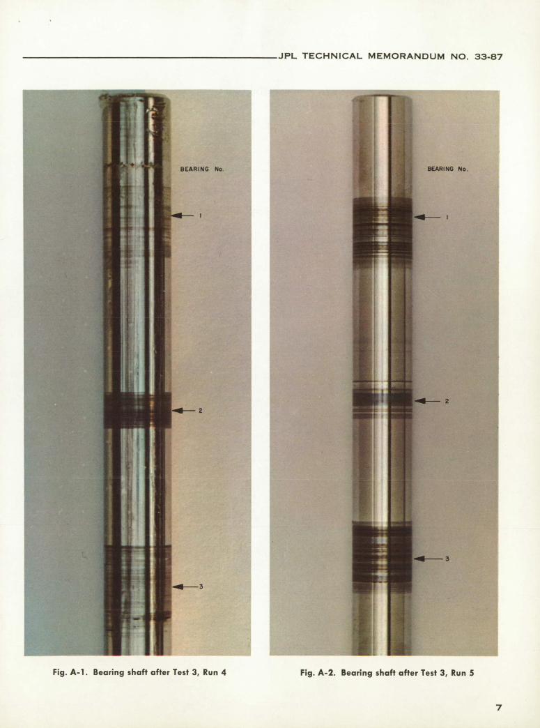
The bearing ran seven hours prior to failure. The shaft was then removed from the tester, inspected, and color photographed (see Fig. A-i). The dark rings were de-posited by the bearings. The smaller deposit in the mid-dle is from the test bearing while the larger, outside pair, are from the line bearings that straddle the test bearing. The middle deposit has a red tinge from copper galled out of the test bearing. By observation, one deducts that the load on the line bearings would be satisfactory for long life while the load on the test bearing is too high. Somewhere between the two loads-270 to 1060 psi—is the threshold load. A load of 700 psi was chosen to try for the 1000-hr. test run.
e. Run 5; 712 psi. This test ran for 826 hours when a building power failure caused the test to terminate. Throughout the test the system coefficient of friction varied between 0.08 and 0.16. When at the low friction-coefficient, the tester ran quietly, but when at the high coefficient, squeaking sounds were audible ten or even twenty feet away from the vacuum equipment. Intermedi-ate values of coefficient of friction were accompanied by squeaks with corresponding degrees of audibility. The silent-squeak-silent cycle occurred on about three dis-tinct occasions, but the same sound less distinct (at times a stethoscope was necessary to detect it) occurred about ten times, with "silence" prevailing only 25% of the time. See Appendix B for the Test 3, Run 5 data sheet.
There was also a deep rumbling background sound that was clearly distinct from the sharp high squeaks. While an explanation is given for the squeaks in the test explanation section, none is given for the deeper sounds.
See Fig. A-2 for a photograph of the shaft after Test 3, Run 5.
JPL TECHNICAL MEMORANDUM NO. 33-87
BEARING No ARING No.
—2
2
—3
3
Fig. A-i. Bearing shaft after Test 3, Run 4 Fig. A-2. Bearing shaft after Test 3, Run 5
7

JPL TECHNICAL MEMORANDUM NO. 33-87
APPENDIX B
Data Sheet for Test 3, Run 5
SELF - ALIGNING Running data SPHERICAL STEEL BEARING Torque Varied at random between 1.5 and 3.0
lb in-lbs throughout the test. High torque accompanied by squeaking sounds.
25 lb I System coefflient of friction 25 lb Varied from 0.08 to 0.16 throughout the
test.
PULLEY g6F Thermal gradient TEST BEARING (No 2) I
Thermocouple No. 1
LINE BEARING LINE BEARING (bearing wall): 133°F (No. 1) (No.3)
0.375 in. Thermocouple No. 2 0.37 5 in.
THERMOCOUPLE No I (aluminum insert): 133°F
THERMOCOUPLE No 2 Thermocouple No. 3
THERMOCOUPLE No. 3 ALUMINUM INSERT (spherical bearing): 132°F
THERMOCOUPLE No.4 0.188 ,i STEEL HOUSING Thermocouple No. 4 (housing): 128°F Note: Interfaces were clean "as fabri-cated"; they were dirty only from normal shop handling.
THERMOCOUPLE No. I WAS WELDED TO THE SIDE
ALL BEARINGS WERE MADE OF THE SAME MATERIAL Bearing wear on radius in direction of load
OF THE TEST BEARING Bearing No. 2: 0.0014 in. on the radius Bearing No. 1: 0.0001 in. on the radius
Fig. B-i. Bearing-tester setup Bearing No. 3: 0.0001 in. on the radius
Test started 2 Nov. 1961 Wear rate on the radius
Test terminated 7 Dec. 1961 Bearing No. 2: 1.69 X 10' in. wear/hr
Total running time 826 hrs Bearing No. 1: 1.2 X 1O in. wear/hr
Pressure 5 X 10 mm Hg Bearing No. 3: 1.21 X 10 in. wear/hr
Ambient temperature 70°F (room)
Shaft Wear rate per unit load on the radius
Size 3/8-in. diam nominal Bearing No. 2: 2.38 X 10 in. wear/hr/
Material AISI 440C stainless psi
Heat treat 277,000 psi Bearing No. 1: 6.8 X 10 10 in. wear/hr/
Finish 2.5 to 4.5 rms A in. psi
Speed Bearing No. 3: 6.8 X 10 0 in. wear/hr/
rpm 100 psi
Surface 9.9 ft/mm Note: The ratio of the wear rate per unit
Radial force load of the test bearing (No. 2) to either
Total load Line bearing: 25 lbs line bearing (No. 1 or No. 3) is 3.5 to 1.
Test bearing: 50 lbs The high wear rate of Bearing No. 2, in
Unit load Line bearing: 178 psi addition to the copper it deposited on the
Test bearing: 712 psi shaft, indicates that it was wearing in a
Initial clearance manner different from that of the other
Bearing No. 2 0.0007 in. on the diam bearings. Hence the conclusion that a
Bearing No. 1 0.0010 in. on the diam load of 700 psi is too high for normal run-
Bearing No. 3 0.0009 in. on the diam ning in a long-duration vacuum operation.