TECHNICAL MANUALANCHORS & FASTENING SYSTEMS

• Fully featured and easy to use web-based interface
• Easy 5 step anchor design with 3D modelling of fastening
• Professional specification of DEWALT fastenings to ETA guidelines
• Customised anchor design facility
CALCULATIONS AND SPECIFICATION FOR CONSTRUCTION
KEEP PACE WITH CHANGING CONSTRUCTION ENVIRONMENTS WITH DEWALT DESIGN ASSIST.
FOR MORE INFORMATION VISIT WWW.DEWALTDESIGNASSIST.COM
ONLINE ANCHOR DESIGN SOFTWARE

Table of conTenTs
TecH
Man
Ual
– ©
2014
DeW
alT
Vol
UMe
1 6/
2014
1www.DEWALT.com
GEN
ERAL
INFO
RM
ATI
ON
Disclaimer for Recommendations, Information and Use of DataThe recommendations, information and data contained in this manual are put together with the greatest care and accuracy possible. It is based on principles, equations and safety factors set out in the technical documentation of DEWALT anchors & fasteners, Inc. that are believed to be correct and current as of June 1, 2014. The information and data is subject to change after such date as DEWALT anchors & fasteners, Inc. reserves the right to change the designs, materials and specifications of the products in this manual without notice.
It is the responsibility of the design professional to ensure that a suitable product is selected, properly designed and used in the intended application. This includes that the selected product and its use is compliant with the applicable building codes and other legal requirements and will satisfy durability and performance criteria and margins of safety which they determine are applicable. The products must be used, handled, applied and installed strictly in accordance with all current instructions for use published by DEWALT anchors & fasteners, Inc.
The performance data given in this manual are the result of the evaluation of tests conducted under laboratory conditions. It is the responsibility of the designer and installer in charge to consider the conditions on site and to ensure the performance data given in the manual is applicable to the actual conditions. In particular the base material and environmental conditions have to be checked prior to installation. In case of doubt, contact the technical support of DEWALT anchors & fasteners, Inc.
Limitation of Liability
DEWALT anchors & fasteners, Inc. offers a limited product warranty to customers or end users that the product meets its applicable specifications. except for the express warranty in the immediately preceding sentence, DEWALT anchors & fasteners, Inc. grants no other warranties, express or implied, regarding the products, their fitness for any purpose, their quality, their merchantability or otherwise. further, DEWALT anchors & fasteners, Inc. shall have no liability with respect to changes in the design, materials and specifications in the products presented in this manual, nor with respect to any product which has been modified or installed improperly, regardless of any specific instructions
to the installer. The responsible designer and installer shall indemnify, defend, and hold harmless DEWALT anchors & fasteners, Inc. for any and all claimed loss or damage occasioned, in a whole or in part, by the modified products or deviation in product installation procedures.
Limitation of Damages
DEWALT anchors & fasteners, Inc. or its affiliates or their respective officers, members, managers, directors, representatives, agents or employees are not obligated for direct, indirect, incidental or consequential damages, losses or expenses in connection with, or by reason of, the use of, or inability to use the products for any purpose. Implied warranties of merchantability or fitness for a particular purpose are specifically excluded.
DEWALT anchors & fasteners, Inc.
black-&-Decker-straße 40
65510 Idstein
Germany
TABLE OF CONTENTS
Gene
ral I
nfor
mat
ion Introduction 2
Icons Used In This Manual 3
Notations Used In This Manual 5
Selection Guide 6
Technical Support 8
Mec
hani
cal A
ncho
rs
Mechanical Anchors 9
Throughbolt
PTb-PRo carbon steel Zinc Plated 10
PTb-PRo Part 6 approval - carbon steel Zinc Plated 18
PTb-ss-PRo stainless steel 21
Drop-In Anchors
DM-PRo carbon steel Zinc Plated, stainless steel, or Galvanized 27
DM-PRo Part 6 approval - carbon steel Zinc Plated, stainless steel, or Galvanized 34
Screw Anchors
bT (blue-Tip) carbon steel Zinc Plated, stainless steel or Galvanized 38
snake carbon steel Zinc Plated 46
Adhe
sive
Anc
hors
Adhesive Anchors 51
Vinylester
ac100-PRo concrete anchoring system 52
ac100-PRo Masonry anchoring system 64
ac100-PRo Rebar anchoring system 71
Epoxy
Pure150-PRo concrete anchoring system 77
Pure150-PRo core Drilled concrete anchoring system 89
Pure150-PRo Rebar anchoring system 100
Pure110-PRo concrete anchoring system 106
Polyester
PV50-PRo concrete anchoring system 118
PV45-PRo concrete anchoring system 127
PV45-PRo Masonry anchoring system 135Capsule sc-PRo concrete anchoring system 142
ANCHORING & FASTENING SYSTEMSTechnical Manual for the Design Professional
2
ancHoR DesIGn ManUal
TecH ManUal – ©
2014 DeW
alT VolUMe 1 6/2014
www.DEWALT.com
GEN
ERAL IN
FORM
ATIO
N
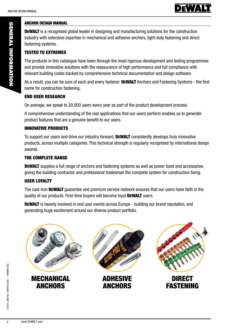
ANCHOR DESIGN MANUAL
DEWALT is a recognised global leader in designing and manufacturing solutions for the construction industry with extensive expertise in mechanical and adhesive anchors, light-duty fastening and direct fastening systems.
TESTED TO EXTREMES
The products in this catalogue have been through the most rigorous development and testing programmes and provide innovative solutions with the reassurance of high performance and full compliance with relevant building codes backed by comprehensive technical documentation and design software.
as a result, you can be sure of each and every fastener. DEWALT anchors and fastening systems - the first name for construction fastening.
END USER RESEARCH
on average, we speak to 20,000 users every year as part of the product development process.
a comprehensive understanding of the real applications that our users perform enables us to generate product features that are a genuine benefit to our users.
INNOVATIVE PRODUCTS
To support our users and drive our industry forward, DEWALT consistently develops truly innovative products, across multiple categories. This technical strength is regularly recognised by international design awards.
THE COMPLETE RANGE
DEWALT supplies a full range of anchors and fastening systems as well as power tools and accessories giving the building contractor and professional tradesman the complete system for construction fixing.
USER LOYALTY
The cast-iron DEWALT guarantee and premium service network ensures that our users have faith in the quality of our products. first-time buyers will become loyal DEWALT users.
DEWALT is heavily involved in end user events across europe - building our brand reputation, and generating huge excitement around our diverse product portfolio.
MECHANICAL ANCHORS
ADHESIVE ANCHORS
DIRECT FASTENING
Icons UseD In THIs ManUal
TecH
Man
Ual
– ©
2014
DeW
alT
Vol
UMe
1 6/
2014
3www.DEWALT.com
GEN
ERAL
INFO
RM
ATI
ONICONS USED IN THIS MANUAL
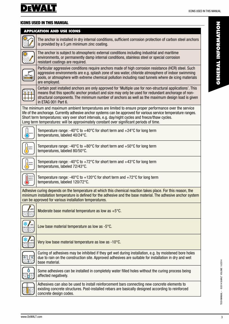
APPLICATION AND USE ICONS
The anchor is installed in dry internal conditions, sufficient corrosion protection of carbon steel anchors is provided by a 5 µm minimum zinc coating.
The anchor is subject to atmospheric external conditions including industrial and maritime environments, or permanently damp internal conditions, stainless steel or special corrosion resistant coatings are required.
Particular aggressive conditions require anchors made of high corrosion resistance (HcR) steel. such aggressive environments are e.g. splash zone of sea water, chloride atmosphere of indoor swimming pools, or atmosphere with extreme chemical pollution including road tunnels where de icing materials are employed.
certain post installed anchors are only approved for ‘Multiple use for non-structural applications’. This means that this specific anchor product and size may only be used for redundant anchorage of non-structural components. The minimum number of anchors as well as the maximum design load is given in eTaG 001 Part 6.
The minimum and maximum ambient temperatures are limited to ensure proper performance over the service life of the anchorage. currently adhesive anchor systems can be approved for various service temperature ranges. short term temperatures: vary over short intervals, e.g. day/night cycles and freeze/thaw cycles. long term temperatures: will be approximately constant over significant periods of time.
40/24˚CTemperature range: -40°c to +40°c for short term and +24°c for long term temperatures, labeled 40/24°c.
40/24˚C
80/50˚C Temperature range: -40°c to +80°c for short term and +50°c for long term temperatures, labeled 80/50°c.
40/24˚C
72/43˚C Temperature range: -40°c to +72°c for short term and +43°c for long term temperatures, labeled 72/43°c.
40/24˚C
80/50˚C
120/72˚C Temperature range: -40°c to +120°c for short term and +72°c for long term temperatures, labeled 120/72°c.
adhesive curing depends on the temperature at which this chemical reaction takes place. for this reason, the minimum installation temperature is defined for the adhesive and the base material. The adhesive anchor system can be approved for various installation temperatures.
+5˚C Moderate base material temperature as low as +5°c.
-5˚C low base material temperature as low as -5°c.
-10 C̊ Very low base material temperature as low as -10°c.
curing of adhesives may be inhibited if they get wet during installation, e.g. by moistened bore holes due to rain on the construction site. approved adhesives are suitable for installation in dry and wet base material.
some adhesives can be installed in completely water filled holes without the curing process being affected negatively.
adhesives can also be used to install reinforcement bars connecting new concrete elements to existing concrete structures. Post-installed rebars are basically designed according to reinforced concrete design codes.
4
Icons UseD In THIs ManUal
TecH ManUal – ©
2014 DeW
alT VolUMe 1 6/2014
www.DEWALT.com
GEN
ERAL IN
FORM
ATIO
N
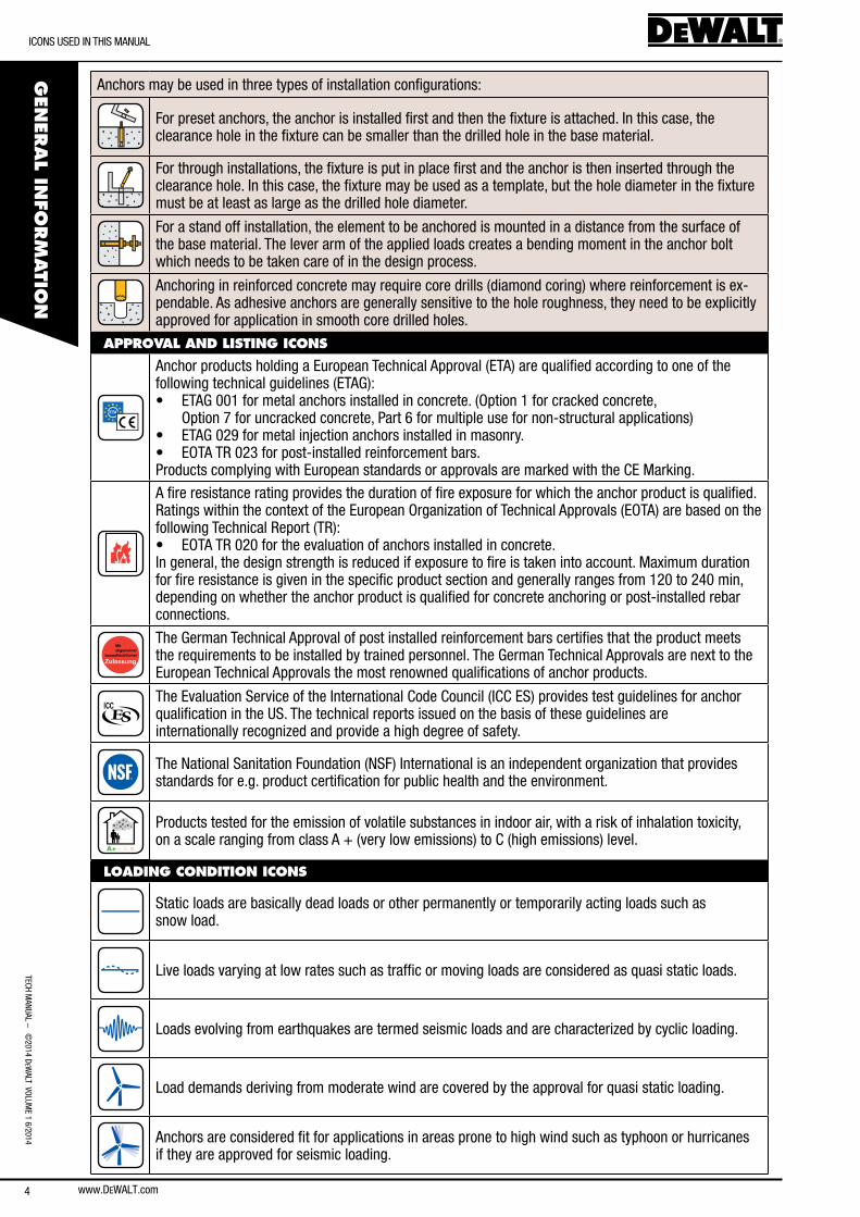
anchors may be used in three types of installation configurations:
for preset anchors, the anchor is installed first and then the fixture is attached. In this case, the clearance hole in the fixture can be smaller than the drilled hole in the base material.
for through installations, the fixture is put in place first and the anchor is then inserted through the clearance hole. In this case, the fixture may be used as a template, but the hole diameter in the fixture must be at least as large as the drilled hole diameter.
for a stand off installation, the element to be anchored is mounted in a distance from the surface of the base material. The lever arm of the applied loads creates a bending moment in the anchor bolt which needs to be taken care of in the design process.
anchoring in reinforced concrete may require core drills (diamond coring) where reinforcement is ex-pendable. as adhesive anchors are generally sensitive to the hole roughness, they need to be explicitly approved for application in smooth core drilled holes.
APPROVAL AND LISTING ICONS
anchor products holding a european Technical approval (eTa) are qualified according to one of the following technical guidelines (eTaG):• eTaG 001 for metal anchors installed in concrete. (option 1 for cracked concrete,
option 7 for uncracked concrete, Part 6 for multiple use for non-structural applications)• eTaG 029 for metal injection anchors installed in masonry.• eoTa TR 023 for post-installed reinforcement bars. Products complying with european standards or approvals are marked with the ce Marking.
a fire resistance rating provides the duration of fire exposure for which the anchor product is qualified. Ratings within the context of the european organization of Technical approvals (eoTa) are based on the following Technical Report (TR):• eoTa TR 020 for the evaluation of anchors installed in concrete. In general, the design strength is reduced if exposure to fire is taken into account. Maximum duration for fire resistance is given in the specific product section and generally ranges from 120 to 240 min, depending on whether the anchor product is qualified for concrete anchoring or post-installed rebar connections.
The German Technical approval of post installed reinforcement bars certifies that the product meets the requirements to be installed by trained personnel. The German Technical approvals are next to the european Technical approvals the most renowned qualifications of anchor products.
The evaluation service of the International code council (Icc es) provides test guidelines for anchor qualification in the Us. The technical reports issued on the basis of these guidelines are internationally recognized and provide a high degree of safety.
The national sanitation foundation (nsf) International is an independent organization that provides standards for e.g. product certification for public health and the environment.
A+ A B C
Products tested for the emission of volatile substances in indoor air, with a risk of inhalation toxicity, on a scale ranging from class a + (very low emissions) to c (high emissions) level.
LOADING CONDITION ICONS
static loads are basically dead loads or other permanently or temporarily acting loads such as snow load.
live loads varying at low rates such as traffic or moving loads are considered as quasi static loads.
loads evolving from earthquakes are termed seismic loads and are characterized by cyclic loading.
load demands deriving from moderate wind are covered by the approval for quasi static loading.
anchors are considered fit for applications in areas prone to high wind such as typhoon or hurricanes if they are approved for seismic loading.
GeneRal safeTy concePT:
TecH
Man
Ual
– ©
2014
DeW
alT
Vol
UMe
1 6/
2014
5www.DEWALT.com
GEN
ERAL
INFO
RM
ATI
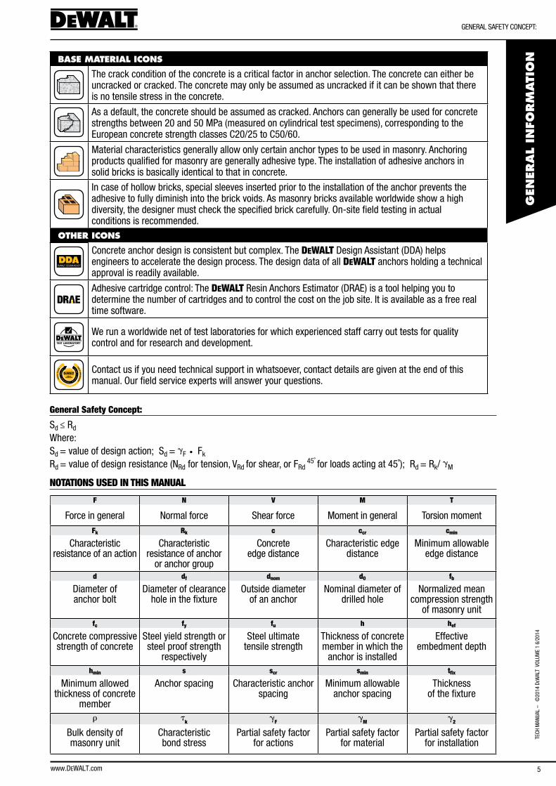
ONBASE MATERIAL ICONS
The crack condition of the concrete is a critical factor in anchor selection. The concrete can either be uncracked or cracked. The concrete may only be assumed as uncracked if it can be shown that there is no tensile stress in the concrete.
as a default, the concrete should be assumed as cracked. anchors can generally be used for concrete strengths between 20 and 50 MPa (measured on cylindrical test specimens), corresponding to the european concrete strength classes c20/25 to c50/60.
Material characteristics generally allow only certain anchor types to be used in masonry. anchoring products qualified for masonry are generally adhesive type. The installation of adhesive anchors in solid bricks is basically identical to that in concrete.
In case of hollow bricks, special sleeves inserted prior to the installation of the anchor prevents the adhesive to fully diminish into the brick voids. as masonry bricks available worldwide show a high diversity, the designer must check the specified brick carefully. on-site field testing in actual conditions is recommended.
OTHER ICONS
concrete anchor design is consistent but complex. The DEWALT Design assistant (DDa) helps engineers to accelerate the design process. The design data of all DEWALT anchors holding a technical approval is readily available.
adhesive cartridge control: The DEWALT Resin anchors estimator (DRae) is a tool helping you to determine the number of cartridges and to control the cost on the job site. It is available as a free real time software.
TEST LABORATORY
We run a worldwide net of test laboratories for which experienced staff carry out tests for quality control and for research and development.
PL
AN
•
D
ES
IGN • PROCU
RE
• B
UI L
D
FIELDSERVICES
FIE
LD
SA
LE
S
FIELD
EN
GIN
EE
RS
contact us if you need technical support in whatsoever, contact details are given at the end of this manual. our field service experts will answer your questions.
General Safety Concept:
sd ≤ Rd
Where: sd = value of design action; sd = gf • fk
Rd = value of design resistance (nRd for tension, VRd for shear, or fRd 45˚ for loads acting at 45˚); Rd = Rk/ gM
NOTATIONS USED IN THIS MANUAL
F N V M T
force in general normal force shear force Moment in general Torsion momentFk Rk c ccr cmin
characteristic resistance of an action
characteristic resistance of anchor
or anchor group
concrete edge distance
characteristic edge distance
Minimum allowable edge distance
d df dnom d0 fb
Diameter of anchor bolt
Diameter of clearance hole in the fixture
outside diameter of an anchor
nominal diameter of drilled hole
normalized mean compression strength
of masonry unitfc fy fu h hef
concrete compressive strength of concrete
steel yield strength or steel proof strength
respectively
steel ultimate tensile strength
Thickness of concrete member in which the
anchor is installed
effective embedment depth
hmin s scr smin tfix
Minimum allowed thickness of concrete
member
anchor spacing characteristic anchor spacing
Minimum allowable anchor spacing
Thickness of the fixture
r tk
gF
gM
g2
bulk density of masonry unit
characteristic bond stress
Partial safety factor for actions
Partial safety factor for material
Partial safety factor for installation
6
selecTIon GUIDe
TecH ManUal – ©
2014 DeW
alT VolUMe 1 6/2014
www.DEWALT.com
GEN
ERAL IN
FORM
ATIO
N
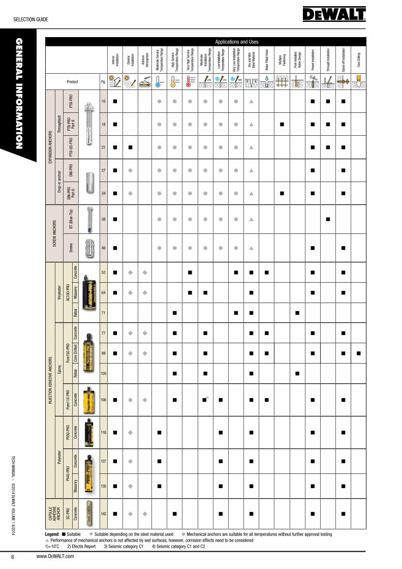
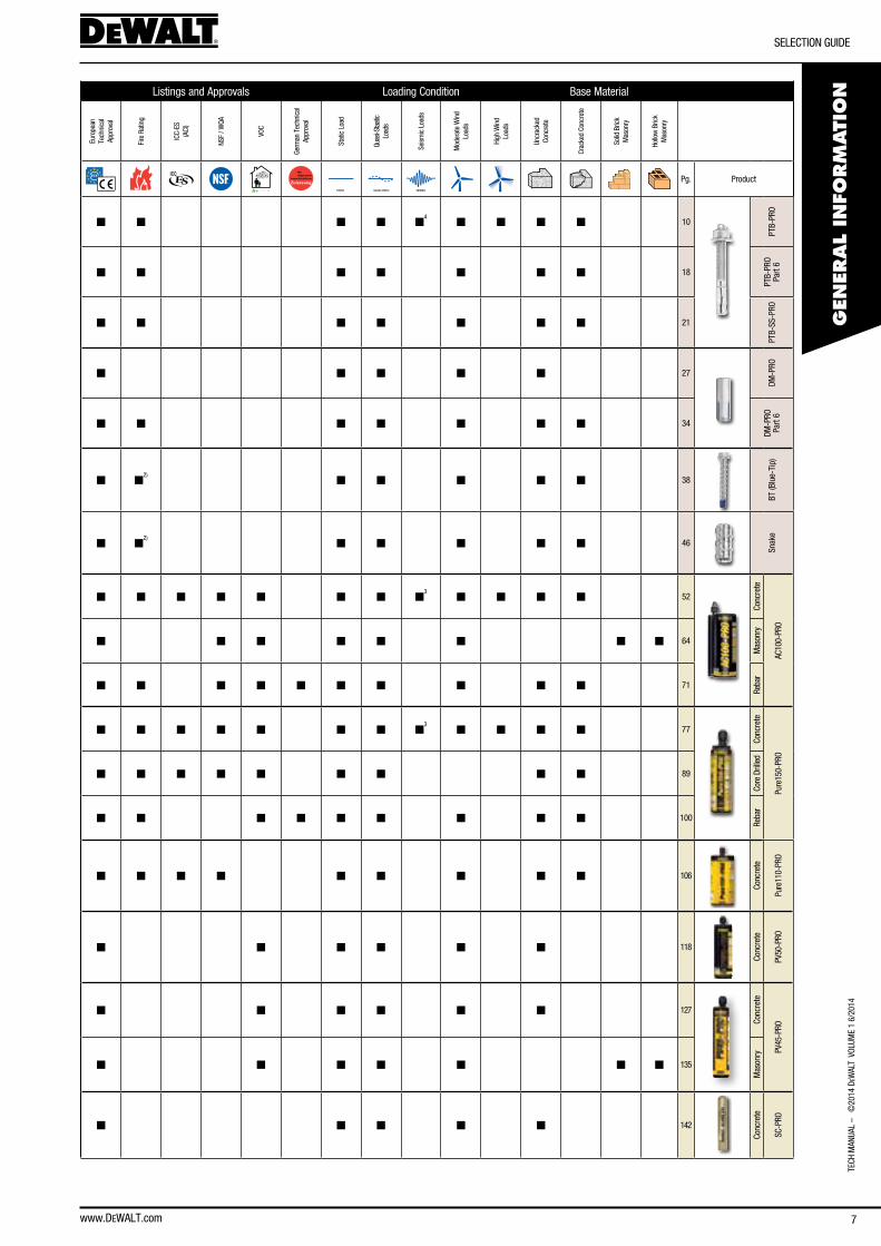
applications and Uses listings and approvals loading condition base Material
SELECTION GUIDE Inte
rior
Inst
alla
tion
exte
rior
Inst
alla
tion
adve
rse
atm
osph
ere
Mod
erat
e se
rvic
e Te
mpe
ratu
re R
ange
High
ser
vice
Tem
pera
ture
Ran
ge
Very
Hig
h se
rvic
e Te
mpe
ratu
re R
ange
Mod
erat
e In
stal
latio
nTe
mpe
ratu
re R
ange
low
Insta
llatio
nTe
mpe
ratu
re R
ange
Very
low
Inst
alla
tion
Tem
pera
ture
Ran
ge
Dry
and
Wet
ba
se M
ater
ial
Wat
er f
illed
Hole
s
Mul
tiple
fast
enin
g
Post
-Inst
alle
dRe
bar D
esig
n
Pres
et In
stal
latio
n
Thro
ugh
Inst
alla
tion
stan
d-of
f Ins
talla
tion
core
Dril
ling
euro
pean
Te
chni
cal
appr
oval
fire
Rat
ing
Icc-
es(a
cI)
nsf
/ WQa
Voc
Germ
an T
echn
ical
ap
prov
al
stat
ic l
oad
Quas
i-sta
atic
lo
ads
seism
ic l
oads
Mod
erat
e W
ind
load
s
High
Win
d
load
s
Uncr
acke
d co
ncre
te
crac
ked
conc
rete
solid
bric
k
Mas
onry
Hollo
w b
rick
Mas
onry
Product Pg. 40/24˚C 40/24˚C
72/43˚C40/24˚C
80/50˚C
120/72˚C
+5˚C -5˚C -10 C̊
ETAG 001 Option 1 F30A+ A B C STATIC QUASI-STATIC SEISMIC
Pg. Product
eXPa
nsIo
n an
cHoR
s Thro
ughb
olt
PTb-
PRo
10 n l l l l l l s n n n n n n n n4
n n n n 10
PTb-
PRo
PTb-
PRo
Part
6
18 n l l l l l l s n n n n n n n n n n n 18
PTb-
PRo
Part
6
PTb-
ss-P
Ro
21 n n l l l l l l s n n n n n n n n n n 21
PTb-
ss-P
Ro
Drop
-in a
ncho
r
DM-P
Ro
27 n u l l l l l l s n n n n n n n 27
DM-P
Ro
DM-P
Ro
Part
6
34 n u l l l l l l s n n n n n n n n n n 34
DM-P
Ro
Part
6
scRe
W a
ncHo
Rs
bT (b
lue-
Tip)
38 n l l l l l l s n n n2)
n n n n n 38
bT (b
lue-
Tip)
snak
e
46 n l l l l l l s n n n n2)
n n n n n 46
snak
e
InJe
cTIo
n aD
HesI
Ve a
ncHo
Rs
Viny
lest
er
ac10
0-PR
o
conc
rete
52 n u u n n n n n n n n n n n n n n3
n n n n 52
conc
rete
ac10
0-PR
o
Mas
onry
64 n u u n n n n n n n n n n n n n 64
Mas
onry
Reba
r
71 n n n n n n n n n n n n n n 71
Reba
r
epox
y
Pure
150-
PRo
conc
rete
77 n u u n n n n n n n n n n n n n n3
n n n n 77
conc
rete
Pure
150-
PRo
core
Dril
led
89 n u u n n n n n n n n n n n n n n n n 89
core
Dril
led
Reba
r
100 n n n n n n n n n n n n n 100
Reba
r
Pure
110-
PRo
conc
rete
106 n u u n n1)
n n n n n n n n n n n n n n 106
conc
rete
Pure
110-
PRo
Poly
este
r
PV50
-PRo
conc
rete
118 n u n n n n n n n n n n n 118
conc
rete
PV50
-PRo
PV45
-PRo
conc
rete
127 n u n n n n n n n n n n n 127
conc
rete
PV45
-PRo
Mas
onry
135 n u n n n n n n n n n n n n 135
Mas
onry
caPs
Ule
aDHe
sIVe
an
cHoR
sc-P
Ro
conc
rete
142 n u u n n n n n n n n n n 142
conc
rete
sc-P
Ro
Legend: n suitable u suitable depending on the steel material used l Mechanical anchors are suitable for all temperatures without further approval testing s Performance of mechanical anchors is not affected by wet surfaces, however, corrosion effects need to be considered 1)+10˚c 2) efectis Report 3) seismic category c1 4) seismic category c1 and c2
selecTIon GUIDe
TecH
Man
Ual
– ©
2014
DeW
alT
Vol
UMe
1 6/
2014
7www.DEWALT.com
GEN
ERAL
INFO
RM
ATI
ONapplications and Uses listings and approvals loading condition base Material
SELECTION GUIDE Inte
rior
Inst
alla
tion
exte
rior
Inst
alla
tion
adve
rse
atm
osph
ere
Mod
erat
e se
rvic
e Te
mpe
ratu
re R
ange
High
ser
vice
Tem
pera
ture
Ran
ge
Very
Hig
h se
rvic
e Te
mpe
ratu
re R
ange
Mod
erat
e In
stal
latio
nTe
mpe
ratu
re R
ange
low
Insta
llatio
nTe
mpe
ratu
re R
ange
Very
low
Inst
alla
tion
Tem
pera
ture
Ran
ge
Dry
and
Wet
ba
se M
ater
ial
Wat
er f
illed
Hole
s
Mul
tiple
fast
enin
g
Post
-Inst
alle
dRe
bar D
esig
n
Pres
et In
stal
latio
n
Thro
ugh
Inst
alla
tion
stan
d-of
f Ins
talla
tion
core
Dril
ling
euro
pean
Te
chni
cal
appr
oval
fire
Rat
ing
Icc-
es(a
cI)
nsf
/ WQa
Voc
Germ
an T
echn
ical
ap
prov
al
stat
ic l
oad
Quas
i-sta
atic
lo
ads
seism
ic l
oads
Mod
erat
e W
ind
load
s
High
Win
d
load
s
Uncr
acke
d co
ncre
te
crac
ked
conc
rete
solid
bric
k
Mas
onry
Hollo
w b
rick
Mas
onry
Product Pg. 40/24˚C 40/24˚C
72/43˚C40/24˚C
80/50˚C
120/72˚C
+5˚C -5˚C -10 C̊
ETAG 001 Option 1 F30A+ A B C STATIC QUASI-STATIC SEISMIC
Pg. Product
eXPa
nsIo
n an
cHoR
s Thro
ughb
olt
PTb-
PRo
10 n l l l l l l s n n n n n n n n4
n n n n 10
PTb-
PRo
PTb-
PRo
Part
6
18 n l l l l l l s n n n n n n n n n n n 18
PTb-
PRo
Part
6
PTb-
ss-P
Ro
21 n n l l l l l l s n n n n n n n n n n 21
PTb-
ss-P
Ro
Drop
-in a
ncho
r
DM-P
Ro
27 n u l l l l l l s n n n n n n n 27
DM-P
Ro
DM-P
Ro
Part
6
34 n u l l l l l l s n n n n n n n n n n 34
DM-P
Ro
Part
6
scRe
W a
ncHo
Rs
bT (b
lue-
Tip)
38 n l l l l l l s n n n2)
n n n n n 38
bT (b
lue-
Tip)
snak
e
46 n l l l l l l s n n n n2)
n n n n n 46
snak
e
InJe
cTIo
n aD
HesI
Ve a
ncHo
Rs
Viny
lest
er
ac10
0-PR
o
conc
rete
52 n u u n n n n n n n n n n n n n n3
n n n n 52
conc
rete
ac10
0-PR
o
Mas
onry
64 n u u n n n n n n n n n n n n n 64
Mas
onry
Reba
r
71 n n n n n n n n n n n n n n 71
Reba
r
epox
y
Pure
150-
PRo
conc
rete
77 n u u n n n n n n n n n n n n n n3
n n n n 77
conc
rete
Pure
150-
PRo
core
Dril
led
89 n u u n n n n n n n n n n n n n n n n 89
core
Dril
led
Reba
r
100 n n n n n n n n n n n n n 100
Reba
r
Pure
110-
PRo
conc
rete
106 n u u n n1)
n n n n n n n n n n n n n n 106
conc
rete
Pure
110-
PRo
Poly
este
r
PV50
-PRo
conc
rete
118 n u n n n n n n n n n n n 118
conc
rete
PV50
-PRo
PV45
-PRo
conc
rete
127 n u n n n n n n n n n n n 127
conc
rete
PV45
-PRo
Mas
onry
135 n u n n n n n n n n n n n n 135
Mas
onry
caPs
Ule
aDHe
sIVe
an
cHoR
sc-P
Ro
conc
rete
142 n u u n n n n n n n n n n 142
conc
rete
sc-P
Ro
8
TecHnIcal sUPPoRT
TecH ManUal – ©
2014 DeW
alT VolUMe 1 6/2014
www.DEWALT.com
GEN
ERAL IN
FORM
ATIO
N
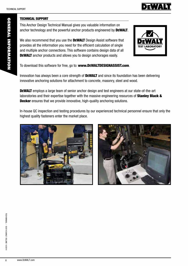
TECHNICAL SUPPORT
This anchor Design Technical Manual gives you valuable information on anchor technology and the powerful anchor products engineered by DEWALT.
We also recommend that you use the DEWALT Design assist software that provides all the information you need for the efficient calculation of single and multiple anchor connections. This software contains design data of all DEWALT anchor products and allows you to design anchorages easily.
To download this software for free, go to: www.DEWALTDESIGNASSIST.com.
Innovation has always been a core strength of DEWALT and since its foundation has been delivering innovative anchoring solutions for attachment to concrete, masonry, steel and wood.
DEWALT employs a large team of senior anchor design and test engineers at our state-of-the-art laboratories and their expertise together with the massive engineering resources of Stanley Black & Decker ensures that we provide innovative, high-quality anchoring solutions.
In-house Qc inspection and testing procedures by our experienced technical personnel ensure that only the highest quality fasteners enter the market place.
TEST LABORATORY
TecH
Man
Ual
– ©
2014
DeW
alT
Vol
UMe
1 6/
2014
MEC
HAN
ICAL
AN
CHO
RS
MecHanIcal ancHoR oVeRVIeW
www.DEWALT.com
SECTION CONTENTExpansion Anchors
Throughbolt:
PTb-PRo
PTb-ss-PRo
Drop-in anchor:
DM-PRo
Screw Anchors
bT (blue-Tip)
snake
MECHANICAL ANCHOR OVERVIEW
Mechanical anchors are available in many variations and choices and can usually be loaded immediately after installation which is an advantage in many applications. Mechanical anchors may also have a greater resistance to the effects of elevated temperature when compared width adhesive anchors.
Mechanical anchors can be described by their functional principle and categorized by their load transfer mechanism which either bases on mechanical friction or on mechanical interlock:
anchor types which load transfer mechanism bases on friction are in general expansion anchors. These anchor types are designed with expansion elements that compress against the wall of the drilled hole. When the anchor is loaded, frictional force between expansion elements and concrete allows the anchor to transfer the load to the base material. Torque-controlled expansion anchors are installed by applying a speci-fied torque to the bolt head or nut with a torque wrench. Torque-controlled expansion anchors may be further classified as either sleeve type (also commonly named ‘heavy duty anchor’ or ‘high load anchor’) or bolt type (also commonly named ‘wedge anchor’ or ‘throughbolt’). Displacement-controlled expansion anchors are set by the axial displacement of the expansion plug within the sleeve. They are commonly called ‘drop-in anchors’.
anchors which load transfer mechanism bases on interlock are either screw or undercut type. Screw anchors have a thread similar to that of a wood screw which allows the anchor to cut into the base material during installation in a drilled hole. The anchor develops its load capacity by the interlock of the thread and concrete. Undercut anchors provide a bearing area which undercuts into the wall of the drilled hole by a special installation procedure. The large bearing area allows transferring the load into the base material by mechanical interlock.
In europe and many other countries, mechanical anchors are in general designed according the ETAG 001 Annex C Method A. anchors qualified for multiple use for non-structural applications according to eTaG 001 Part 6 are designed according to simplified rules stipulated in ETAG 001 Annex C.
9
www.DEWALT.com10
GeneRal InfoRMaTIon
TecH ManUal – M
ecHanIcal ancHoRs ©2014 D
eWalT VolUM
e 1 6/2014M
ECHAN
ICAL A
NCHO
RS
GeneRal InfoRMaTIon
SECTION CONTENTSGeneral Information
Installation Information
Design Information
Material Information
ordering Information
ASSEMBLY
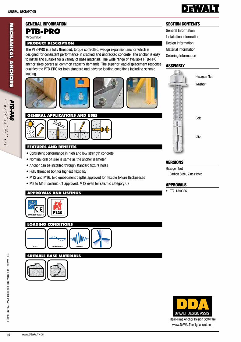
Hexagon nut
Washer
bolt
clip
VERSIONSHexagon nut
carbon steel, Zinc Plated
APPROVALS• eTa-13/0036
GENERAL INFORMATION
PTB-PROThroughbolt
PRODUCT DESCRIPTION
The PTb-PRo is a fully threaded, torque controlled, wedge expansion anchor which is designed for consistent performance in cracked and uncracked concrete. The anchor is easy to install and suitable for a variety of base materials. The wide range of available PTb-PRo anchor sizes covers all common capacity demands. The superior load-displacement response qualifies the PTb-PRo for both standard and adverse loading conditions including seismic loading.
GENERAL APPLICATIONS AND USES
FEATURES AND BENEFITS
• consistent performance in high and low strength concrete
• nominal drill bit size is same as the anchor diameter
• anchor can be installed through standard fixture holes
• fully threaded bolt for highest flexibility
• M12 and M16: two embedment depths approved for flexible fixture thicknesses
• M8 to M16: seismic c1 approved, M12 even for seismic category c2
APPROVALS AND LISTINGS
ETAG 001 Option 1 F120
LOADING CONDITIONS
STATIC QUASI-STATIC SEISMIC
SUITABLE BASE MATERIALS
DEWALT DESIGN ASSISTReal-Time anchor Design software
www.DeWalTdesignassist.com
www.DEWALT.com 11
TecH
Man
Ual
– M
ecHa
nIca
l an
cHoR
s ©
2014
DeW
alT
Vol
UMe
1 6/
2014
InsTallaTIon InfoRMaTIon
MEC
HAN
ICAL
AN
CHO
RSINSTALLATION INFORMATION
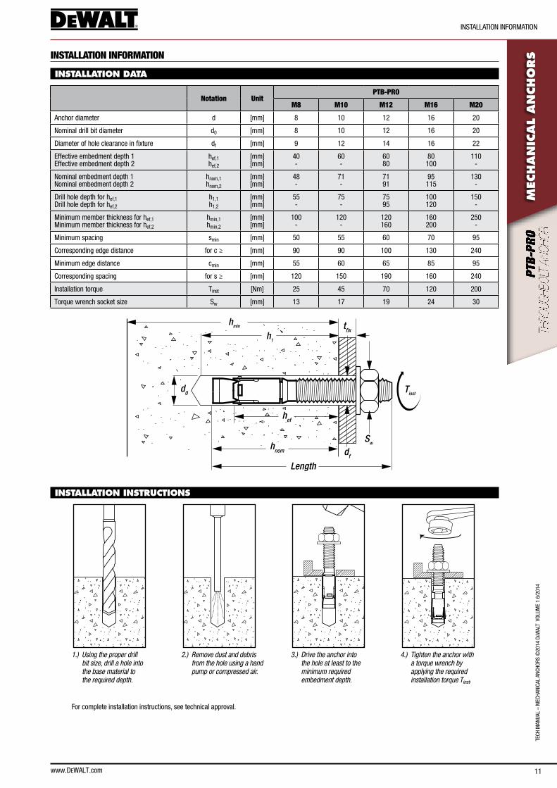
INSTALLATION DATA
Notation UnitPTB-PRO
M8 M10 M12 M16 M20
anchor diameter d [mm] 8 10 12 16 20
nominal drill bit diameter d0 [mm] 8 10 12 16 20
Diameter of hole clearance in fixture df [mm] 9 12 14 16 22
effective embedment depth 1 effective embedment depth 2
hef,1 hef,2
[mm] [mm]
40 -
60 -
60 80
80 100
110 -
nominal embedment depth 1nominal embedment depth 2
hnom,1hnom,2
[mm][mm]
48-
71-
7191
95115
130-
Drill hole depth for hef,1 Drill hole depth for hef,2
h1,1 h1,2
[mm] [mm]
55 -
75 -
75 95
100 120
150 -
Minimum member thickness for hef,1 Minimum member thickness for hef,2
hmin,1 hmin,2
[mm] [mm]
100 -
120 -
120 160
160 200
250 -
Minimum spacing smin [mm] 50 55 60 70 95
corresponding edge distance for c ≥ [mm] 90 90 100 130 240
Minimum edge distance cmin [mm] 55 60 65 85 95
corresponding spacing for s ≥ [mm] 120 150 190 160 240
Installation torque Tinst [nm] 25 45 70 120 200
Torque wrench socket size sw [mm] 13 17 19 24 30
hmin
hef
d0
df
Sw
tfix
Tinst
h1
Length
hnom
INSTALLATION INSTRUCTIONS
1.) Using the proper drill bit size, drill a hole into the base material to the required depth.
2.) Remove dust and debris from the hole using a hand pump or compressed air.
3.) Drive the anchor into the hole at least to the minimum required embedment depth.
4.) Tighten the anchor with a torque wrench by applying the required installation torque Tinst.
for complete installation instructions, see technical approval.
12
TecH ManUal – M
ecHanIcal ancHoRs ©2014 D
eWalT VolUM
e 1 6/2014
DesIGn InfoRMaTIon
www.DEWALT.com
MEC
HAN
ICAL A
NCHO
RS
DESIGN INFORMATION
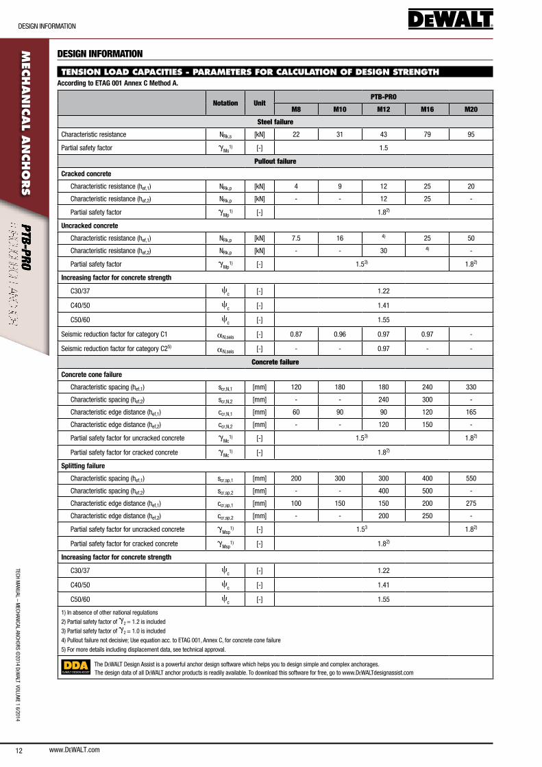
TENSION LOAD CAPACITIES - PARAMETERS FOR CALCULATION OF DESIGN STRENGTHAccording to ETAG 001 Annex C Method A.
Notation UnitPTB-PRO
M8 M10 M12 M16 M20
Steel failure
characteristic resistance nRk,s [kn] 22 31 43 79 95
Partial safety factor gMs
1) [-] 1.5
Pullout failure
Cracked concrete
characteristic resistance (hef,1) nRk,p [kn] 4 9 12 25 20
characteristic resistance (hef,2) nRk,p [kn] - - 12 25 -
Partial safety factor gMp
1) [-] 1.82)
Uncracked concrete
characteristic resistance (hef,1) nRk,p [kn] 7.5 16 4) 25 50
characteristic resistance (hef,2) nRk,p [kn] - - 30 4) -
Partial safety factor gMp
1) [-] 1.53) 1.82)
Increasing factor for concrete strength
c30/37 cc [-] 1.22
c40/50 cc [-] 1.41
c50/60 cc [-] 1.55
seismic reduction factor for category c1 an,seis [-] 0.87 0.96 0.97 0.97 -
seismic reduction factor for category c25) an,seis [-] - - 0.97 - -
Concrete failure
Concrete cone failure
characteristic spacing (hef,1) scr,n,1 [mm] 120 180 180 240 330
characteristic spacing (hef,2) scr,n,2 [mm] - - 240 300 -
characteristic edge distance (hef,1) ccr,n,1 [mm] 60 90 90 120 165
characteristic edge distance (hef,2) ccr,n,2 [mm] - - 120 150 -
Partial safety factor for uncracked concrete gMc
1) [-] 1.53) 1.82)
Partial safety factor for cracked concrete gMc
1) [-] 1.82)
Splitting failure
characteristic spacing (hef,1) scr,sp,1 [mm] 200 300 300 400 550
characteristic spacing (hef,2) scr,sp,2 [mm] - - 400 500 -
characteristic edge distance (hef,1) ccr,sp,1 [mm] 100 150 150 200 275
characteristic edge distance (hef,2) ccr,sp,2 [mm] - - 200 250 -
Partial safety factor for uncracked concrete gMsp
1) [-] 1.53 1.82)
Partial safety factor for cracked concrete gMsp
1) [-] 1.82)
Increasing factor for concrete strength
c30/37 cc [-] 1.22
c40/50 cc [-] 1.41
c50/60 cc [-] 1.55
1) In absence of other national regulations
2) Partial safety factor of g2 = 1.2 is included
3) Partial safety factor of g2 = 1.0 is included
4) Pullout failure not decisive; Use equation acc. to eTaG 001, annex c, for concrete cone failure
5) for more details including displacement data, see technical approval.
DEWALT DESIGN ASSIST
The DeWalT Design assist is a powerful anchor design software which helps you to design simple and complex anchorages.The design data of all DeWalT anchor products is readily available. To download this software for free, go to www.DeWalTdesignassist.com
www.DEWALT.com 13
TecH
Man
Ual
– M
ecHa
nIca
l an
cHoR
s ©
2014
DeW
alT
Vol
UMe
1 6/
2014
DesIGn InfoRMaTIon
MEC
HAN
ICAL
AN
CHO
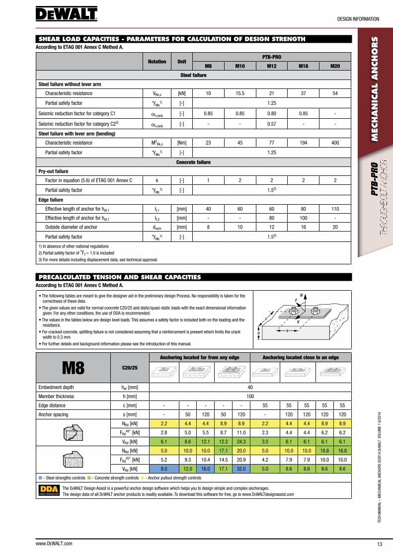
RSSHEAR LOAD CAPACITIES - PARAMETERS FOR CALCULATION OF DESIGN STRENGTH
According to ETAG 001 Annex C Method A.
Notation UnitPTB-PRO
M8 M10 M12 M16 M20
Steel failure
Steel failure without lever arm
characteristic resistance VRk,s [kn] 10 15.5 21 37 54
Partial safety factor gMs
1) [-] 1.25
seismic reduction factor for category c1 av,seis [-] 0.85 0.85 0.80 0.85 -
seismic reduction factor for category c23) av,seis [-] - - 0.57 - -
Steel failure with lever arm (bending)
characteristic resistance M0Rk,s [nm] 23 45 77 194 400
Partial safety factor gMs
1) [-] 1.25
Concrete failure
Pry-out failure
factor in equation (5.6) of eTaG 001 annex c k [-] 1 2 2 2 2
Partial safety factor gMc
1) [-] 1.52)
Edge failure
effective length of anchor for hef,1 lf,1 [mm] 40 60 60 80 110
effective length of anchor for hef,1 lf,2 [mm] - - 80 100 -
outside diameter of anchor dnom [mm] 8 10 12 16 20
Partial safety factor gMc
1) [-] 1.52)
1) In absence of other national regulations
2) Partial safety factor of g2 = 1.0 is included
3) for more details including displacement data, see technical approval.
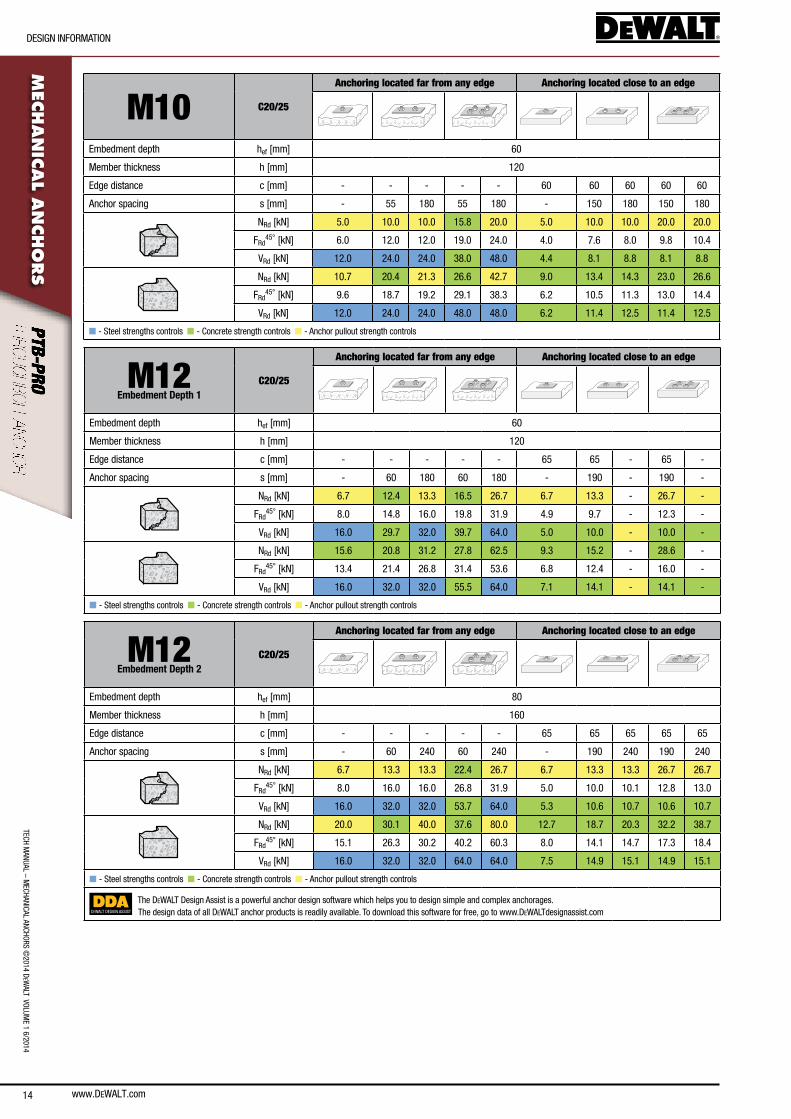
PRECALCULATED TENSION AND SHEAR CAPACITIES According to ETAG 001 Annex C Method A.
• The following tables are meant to give the designer aid in the preliminary design Process. no responsibility is taken for the correctness of these data.
• The given values are valid for normal concrete c20/25 and static/quasi-static loads with the exact dimensional information given. for any other conditions, the use of DDa is recommended.
• The values in the tables below are design level loads. This assumes a safety factor is included both on the loading and the resistance.
• for cracked concrete, splitting failure is not considered assuming that a reinforcement is present which limits the crack width to 0.3 mm.
• for further details and background information please see the introduction of this manual.
N
V
F
sh
c
M8 C20/25
Anchoring located far from any edge Anchoring located close to an edge
embedment depth hef [mm] 40
Member thickness h [mm] 100
edge distance c [mm] - - - - - 55 55 55 55 55
anchor spacing s [mm] - 50 120 50 120 - 120 120 120 120
nRd [kn] 2.2 4.4 4.4 8.9 8.9 2.2 4.4 4.4 8.9 8.9
fRd45° [kn] 2.8 5.0 5.5 8.7 11.0 2.3 4.4 4.4 6.2 6.2
VRd [kn] 6.1 8.6 12.1 12.2 24.3 3.5 6.1 6.1 6.1 6.1
nRd [kn] 5.0 10.0 10.0 17.1 20.0 5.0 10.0 10.0 18.8 18.8
fRd45° [kn] 5.2 9.3 10.4 14.5 20.9 4.2 7.9 7.9 10.0 10.0
VRd [kn] 8.0 12.0 16.0 17.1 32.0 5.0 8.6 8.6 8.6 8.6
n - steel strengths controls n - concrete strength controls n - anchor pullout strength controls
DEWALT DESIGN ASSIST
The DeWalT Design assist is a powerful anchor design software which helps you to design simple and complex anchorages.The design data of all DeWalT anchor products is readily available. To download this software for free, go to www.DeWalTdesignassist.com
14
TecH ManUal – M
ecHanIcal ancHoRs ©2014 D
eWalT VolUM
e 1 6/2014
DesIGn InfoRMaTIon
www.DEWALT.com
MEC
HAN
ICAL A
NCHO
RS
M10 C20/25
Anchoring located far from any edge Anchoring located close to an edge
embedment depth hef [mm] 60
Member thickness h [mm] 120
edge distance c [mm] - - - - - 60 60 60 60 60
anchor spacing s [mm] - 55 180 55 180 - 150 180 150 180
nRd [kn] 5.0 10.0 10.0 15.8 20.0 5.0 10.0 10.0 20.0 20.0
fRd45° [kn] 6.0 12.0 12.0 19.0 24.0 4.0 7.6 8.0 9.8 10.4
VRd [kn] 12.0 24.0 24.0 38.0 48.0 4.4 8.1 8.8 8.1 8.8
nRd [kn] 10.7 20.4 21.3 26.6 42.7 9.0 13.4 14.3 23.0 26.6
fRd45° [kn] 9.6 18.7 19.2 29.1 38.3 6.2 10.5 11.3 13.0 14.4
VRd [kn] 12.0 24.0 24.0 48.0 48.0 6.2 11.4 12.5 11.4 12.5
n - steel strengths controls n - concrete strength controls n - anchor pullout strength controls
M12Embedment Depth 1
C20/25
Anchoring located far from any edge Anchoring located close to an edge
embedment depth hef [mm] 60
Member thickness h [mm] 120
edge distance c [mm] - - - - - 65 65 - 65 -
anchor spacing s [mm] - 60 180 60 180 - 190 - 190 -
nRd [kn] 6.7 12.4 13.3 16.5 26.7 6.7 13.3 - 26.7 -
fRd45° [kn] 8.0 14.8 16.0 19.8 31.9 4.9 9.7 - 12.3 -
VRd [kn] 16.0 29.7 32.0 39.7 64.0 5.0 10.0 - 10.0 -
nRd [kn] 15.6 20.8 31.2 27.8 62.5 9.3 15.2 - 28.6 -
fRd45° [kn] 13.4 21.4 26.8 31.4 53.6 6.8 12.4 - 16.0 -
VRd [kn] 16.0 32.0 32.0 55.5 64.0 7.1 14.1 - 14.1 -
n - steel strengths controls n - concrete strength controls n - anchor pullout strength controls
M12Embedment Depth 2
C20/25
Anchoring located far from any edge Anchoring located close to an edge
embedment depth hef [mm] 80
Member thickness h [mm] 160
edge distance c [mm] - - - - - 65 65 65 65 65
anchor spacing s [mm] - 60 240 60 240 - 190 240 190 240
nRd [kn] 6.7 13.3 13.3 22.4 26.7 6.7 13.3 13.3 26.7 26.7
fRd45° [kn] 8.0 16.0 16.0 26.8 31.9 5.0 10.0 10.1 12.8 13.0
VRd [kn] 16.0 32.0 32.0 53.7 64.0 5.3 10.6 10.7 10.6 10.7
nRd [kn] 20.0 30.1 40.0 37.6 80.0 12.7 18.7 20.3 32.2 38.7
fRd45° [kn] 15.1 26.3 30.2 40.2 60.3 8.0 14.1 14.7 17.3 18.4
VRd [kn] 16.0 32.0 32.0 64.0 64.0 7.5 14.9 15.1 14.9 15.1
n - steel strengths controls n - concrete strength controls n - anchor pullout strength controls
DEWALT DESIGN ASSIST
The DeWalT Design assist is a powerful anchor design software which helps you to design simple and complex anchorages.The design data of all DeWalT anchor products is readily available. To download this software for free, go to www.DeWalTdesignassist.com
www.DEWALT.com 15
TecH
Man
Ual
– M
ecHa
nIca
l an
cHoR
s ©
2014
DeW
alT
Vol
UMe
1 6/
2014
DesIGn InfoRMaTIon
MEC
HAN
ICAL
AN
CHO
RS
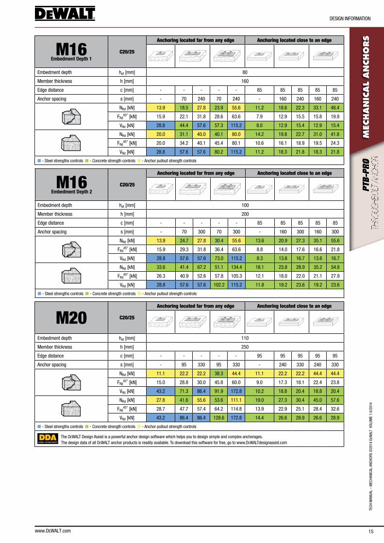
M16Embedment Depth 1
C20/25
Anchoring located far from any edge Anchoring located close to an edge
embedment depth hef [mm] 80
Member thickness h [mm] 160
edge distance c [mm] - - - - - 85 85 85 85 85
anchor spacing s [mm] - 70 240 70 240 - 160 240 160 240
nRd [kn] 13.9 18.5 27.8 23.9 55.6 11.2 18.6 22.3 33.1 48.4
fRd45° [kn] 15.9 22.1 31.8 28.6 63.6 7.9 12.9 15.5 15.8 19.9
VRd [kn] 28.8 44.4 57.6 57.3 115.2 8.0 12.9 15.4 12.9 15.4
nRd [kn] 20.0 31.1 40.0 40.1 80.0 14.2 19.8 22.7 31.0 41.8
fRd45° [kn] 20.0 34.2 40.1 45.4 80.1 10.6 16.1 18.9 19.5 24.3
VRd [kn] 28.8 57.6 57.6 80.2 115.2 11.2 18.3 21.8 18.3 21.8
n - steel strengths controls n - concrete strength controls n - anchor pullout strength controls
M16Embedment Depth 2
C20/25
Anchoring located far from any edge Anchoring located close to an edge
embedment depth hef [mm] 100
Member thickness h [mm] 200
edge distance c [mm] - - - - - 85 85 85 85 85
anchor spacing s [mm] - 70 300 70 300 - 160 300 160 300
nRd [kn] 13.9 24.7 27.8 30.4 55.6 13.6 20.9 27.3 35.1 55.6
fRd45° [kn] 15.9 29.3 31.8 36.4 63.6 8.8 14.0 17.6 16.6 21.8
VRd [kn] 28.8 57.6 57.6 73.0 115.2 8.3 13.6 16.7 13.6 16.7
nRd [kn] 33.6 41.4 67.2 51.1 134.4 18.1 23.8 28.9 35.2 54.8
fRd45° [kn] 26.3 40.9 52.6 57.8 105.3 12.1 18.0 22.0 21.1 27.9
VRd [kn] 28.8 57.6 57.6 102.2 115.2 11.8 19.2 23.6 19.2 23.6
n - steel strengths controls n - concrete strength controls n - anchor pullout strength controls
M20 C20/25
Anchoring located far from any edge Anchoring located close to an edge
embedment depth hef [mm] 110
Member thickness h [mm] 250
edge distance c [mm] - - - - - 95 95 95 95 95
anchor spacing s [mm] - 95 330 95 330 - 240 330 240 330
nRd [kn] 11.1 22.2 22.2 38.3 44.4 11.1 22.2 22.2 44.4 44.4
fRd45° [kn] 15.0 28.8 30.0 45.8 60.0 9.0 17.3 18.1 22.4 23.8
VRd [kn] 43.2 71.3 86.4 91.9 172.8 10.2 18.8 20.4 18.8 20.4
nRd [kn] 27.8 41.6 55.6 53.6 111.1 19.0 27.3 30.4 45.0 57.6
fRd45° [kn] 28.7 47.7 57.4 64.2 114.8 13.9 22.9 25.1 28.4 32.6
VRd [kn] 43.2 86.4 86.4 128.6 172.8 14.4 26.6 28.9 26.6 28.9
n - steel strengths controls n - concrete strength controls n - anchor pullout strength controls
DEWALT DESIGN ASSIST
The DeWalT Design assist is a powerful anchor design software which helps you to design simple and complex anchorages.The design data of all DeWalT anchor products is readily available. To download this software for free, go to www.DeWalTdesignassist.com
16
TecH ManUal – M
ecHanIcal ancHoRs ©2014 D
eWalT VolUM
e 1 6/2014
MaTeRIal InfoRMaTIon
www.DEWALT.com
MEC
HAN
ICAL A
NCHO
RS
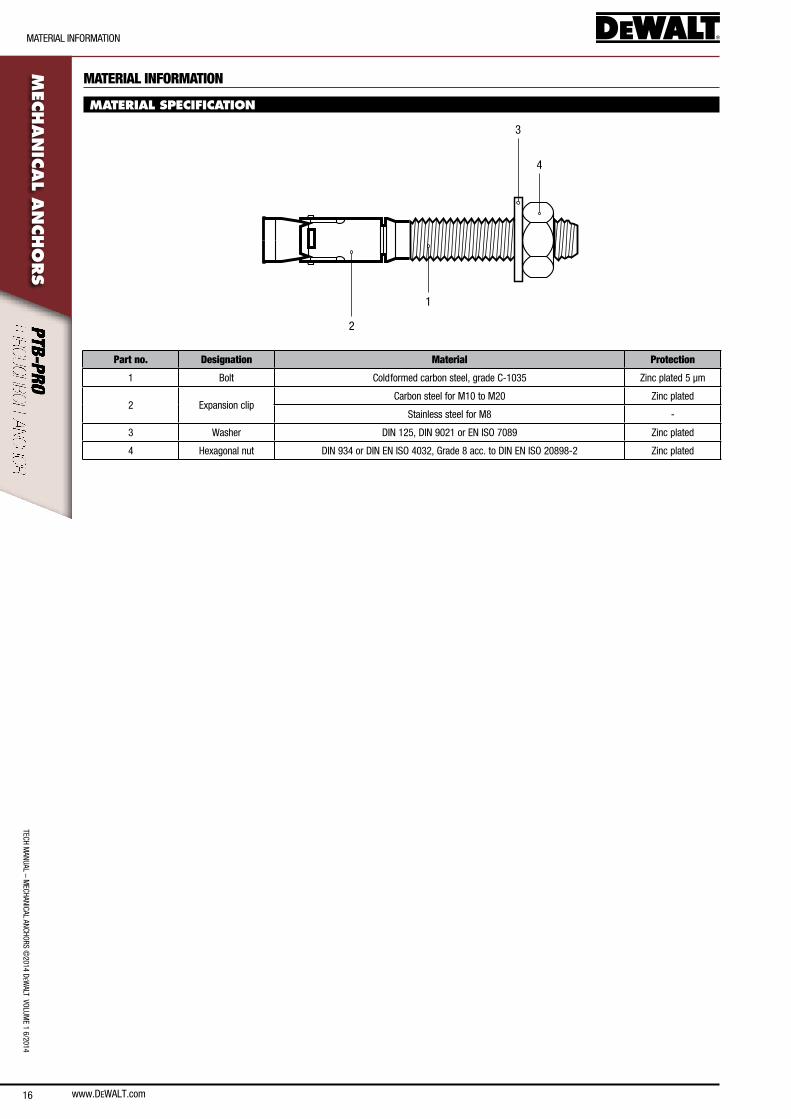
MATERIAL INFORMATION
MATERIAL SPECIFICATION
4
3
1
2
Part no. Designation Material Protection
1 bolt cold formed carbon steel, grade c-1035 Zinc plated 5 µm
2 expansion clipcarbon steel for M10 to M20 Zinc plated
stainless steel for M8 -
3 Washer DIn 125, DIn 9021 or en Iso 7089 Zinc plated
4 Hexagonal nut DIn 934 or DIn en Iso 4032, Grade 8 acc. to DIn en Iso 20898-2 Zinc plated
www.DEWALT.com 17
TecH
Man
Ual
– M
ecHa
nIca
l an
cHoR
s ©
2014
DeW
alT
Vol
UMe
1 6/
2014
oRDeRInG InfoRMaTIon
MEC
HAN
ICAL
AN
CHO
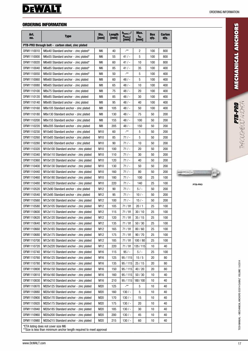
RSORDERING INFORMATION
Art. no. Type Dia.
[mm]Length [mm]
hnom,1 /hnom,2[mm]
Max. tfix
[mm]Box qty.
Carton qty.
PTB-PRO
PTB-PRO through bolt - carbon steel, zinc plated
DfM1110010 M6x40 standard anchor - zinc plated* M6 40 -** 2 100 800
DfM1110000 M6x55 standard anchor - zinc plated* M6 55 41 / - 5 100 800
DfM1110020 M6x60 standard anchor - zinc plated* M6 60 41 / - 10 100 800
DfM1110040 M6x85 standard anchor - zinc plated* M6 85 41 / - 35 100 400
DfM1110050 M8x50 standard anchor - zinc plated* M8 50 -** 5 100 400
DfM1110060 M8x60 standard anchor - zinc plated M8 60 48 / - 5 100 400
DfM1110080 M8x65 standard anchor - zinc plated M8 65 48 / - 10 100 400
DfM1110100 M8x75 standard anchor - zinc plated M8 75 48 / - 20 100 400
DfM1110120 M8x85 standard anchor - zinc plated M8 85 48 / - 30 100 400
DfM1110140 M8x95 standard anchor - zinc plated M8 95 48 / - 40 100 400
DfM1110160 M8x105 standard anchor - zinc plated M8 105 48 / - 50 100 400
DfM1110180 M8x130 standard anchor - zinc plated M8 130 48 / - 75 50 200
DfM1110200 M8x155 standard anchor - zinc plated M8 155 48 / - 100 50 200
DfM1110220 M8x205 standard anchor - zinc plated M8 205 48 / - 150 50 200
DfM1110230 M10x60 standard anchor - zinc plated M10 60 -** 5 50 200
DfM1110260 M10x85 standard anchor - zinc plated M10 85 71 / - 5 50 200
DfM1110280 M10x90 standard anchor - zinc plated M10 90 71 / - 10 50 200
DfM1110320 M10x100 standard anchor - zinc plated M10 100 71 / - 20 50 200
DfM1110340 M10x110 standard anchor - zinc plated M10 110 71 / - 30 50 200
DfM1110360 M10x120 standard anchor - zinc plated M10 120 71 / - 40 50 200
DfM1110400 M10x130 standard anchor - zinc plated M10 130 71 / - 50 50 200
DfM1110440 M10x160 standard anchor - zinc plated M10 160 71 / - 80 50 200
DfM1110460 M10x180 standard anchor - zinc plated M10 180 71 / - 100 25 100
DfM1110480 M10x220 standard anchor - zinc plated M10 220 71 / - 140 25 100
DfM1110520 M12x90 standard anchor - zinc plated M12 90 71 / - 5 / - 50 200
DfM1110540 M12x95 standard anchor - zinc plated M12 95 71 / - 10 / - 50 200
DfM1110560 M12x100 standard anchor - zinc plated M12 100 71 / - 15 / - 50 200
DfM1110580 M12x105 standard anchor - zinc plated M12 105 71 / 91 20 / 1 25 100
DfM1110600 M12x115 standard anchor - zinc plated M12 115 71 / 91 30 / 10 25 100
DfM1110620 M12x120 standard anchor - zinc plated M12 120 71 / 91 35 / 15 25 100
DfM1110640 M12x135 standard anchor - zinc plated M12 135 71 / 91 50 / 30 25 100
DfM1110660 M12x165 standard anchor - zinc plated M12 165 71 / 91 80 / 60 25 100
DfM1110680 M12x175 standard anchor - zinc plated M12 175 71 / 91 90 / 70 25 100
DfM1110700 M12x185 standard anchor - zinc plated M12 185 71 / 91 100 / 80 25 100
DfM1110720 M12x220 standard anchor - zinc plated M12 220 71 / 91 135 / 115 10 40
DfM1110740 M16x115 standard anchor - zinc plated M16 115 95 / - 5 / - 25 100
DfM1110760 M16x125 standard anchor - zinc plated M16 125 95 / 115 15 / 5 20 80
DfM1110780 M16x135 standard anchor - zinc plated M16 135 95 / 115 25 / 15 20 80
DfM1110800 M16x150 standard anchor - zinc plated M16 150 95 / 115 40 / 20 20 80
DfM1110810 M16x160 standard anchor - zinc plated M16 160 95 / 115 50 / 30 10 40
DfM1110830 M16x210 standard anchor - zinc plated M16 210 95 / 115 180 / 100 10 40
DfM1110870 M20x125 standard anchor - zinc plated M20 125 -** 5 10 40
DfM1110880 M20x160 standard anchor - zinc plated M20 160 130 / - 5 10 40
DfM1110900 M20x170 standard anchor - zinc plated M20 170 130 / - 15 10 40
DfM1110920 M20x175 standard anchor - zinc plated M20 175 130 / - 20 10 40
DfM1110940 M20x185 standard anchor - zinc plated M20 185 130 / - 30 10 40
DfM1110960 M20x200 standard anchor - zinc plated M20 200 130 / - 45 10 40
DfM1110980 M20x215 standard anchor - zinc plated M20 215 130 / - 60 10 40
*eTa listing does not cover size M6**size is less than minimum anchor length required to meet approval
18
TecH ManUal – M
ecHanIcal ancHoRs ©2014 D
eWalT VolUM
e 1 6/2014
GeneRal InfoRMaTIon
www.DEWALT.com
MEC
HAN
ICAL A
NCHO
RS
GENERAL INFORMATION
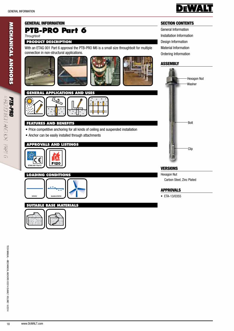
PTB-PRO Part 6Throughbolt
PRODUCT DESCRIPTION
With an eTaG 001 Part 6 approval the PTb-PRo M6 is a small size throughbolt for multiple connection in non-structural applications.
GENERAL APPLICATIONS AND USES
FEATURES AND BENEFITS
• Price competitive anchoring for all kinds of ceiling and suspended installation
• anchor can be easily installed through attachments
APPROVALS AND LISTINGS
ETAG 001 Part 6 F120
LOADING CONDITIONS
STATIC QUASI-STATIC
SUITABLE BASE MATERIALS
SECTION CONTENTSGeneral Information
Installation Information
Design Information
Material Information
ordering Information
ASSEMBLY
Hexagon nut
Washer
bolt
clip
VERSIONSHexagon nut
carbon steel, Zinc Plated
APPROVALS• eTa-13/0355
www.DEWALT.com 19
InsTallaTIon InfoRMaTIon
TecH
Man
Ual
– M
ecHa
nIca
l an
cHoR
s ©
2014
DeW
alT
Vol
UMe
1 6/
2014
MEC
HAN
ICAL
AN
CHO
RSINSTALLATION INFORMATION
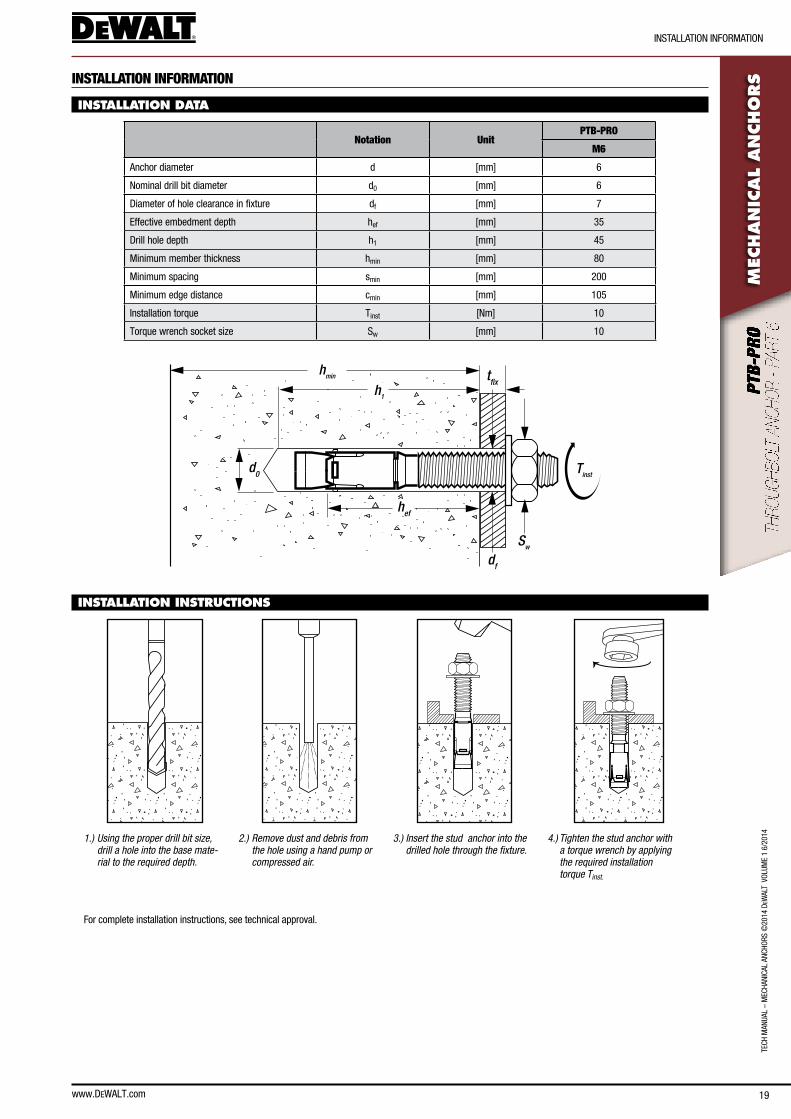
INSTALLATION DATA
Notation UnitPTB-PRO
M6
anchor diameter d [mm] 6
nominal drill bit diameter d0 [mm] 6
Diameter of hole clearance in fixture df [mm] 7
effective embedment depth hef [mm] 35
Drill hole depth h1 [mm] 45
Minimum member thickness hmin [mm] 80
Minimum spacing smin [mm] 200
Minimum edge distance cmin [mm] 105
Installation torque Tinst [nm] 10
Torque wrench socket size sw [mm] 10
hmin
hef
d0
df
Sw
tfix
Tinst
h1
INSTALLATION INSTRUCTIONS
1.) Using the proper drill bit size, drill a hole into the base mate-rial to the required depth.
2.) Remove dust and debris from the hole using a hand pump or compressed air.
3.) Insert the stud anchor into the drilled hole through the fixture.
4.) Tighten the stud anchor with a torque wrench by applying the required installation torque Tinst.
for complete installation instructions, see technical approval.
www.DEWALT.com20
DesIGn InfoRMaTIon
TecH ManUal – M
ecHanIcal ancHoRs ©2014 D
eWalT VolUM
e 1 6/2014M
ECHAN
ICAL A
NCHO
RS
DESIGN INFORMATION
LOAD CAPACITIES - PARAMETERS FOR CALCULATION OF DESIGN STRENGTHAccording to ETAG 001 Annex C Method C.
Notation UnitPTB-PRO
M6
Capacity for all directions and failure modes
Uncracked and cracked concrete
characteristic resistance c20/25 to c50/60 f0Rk [kn] 4.0
Partial safety factor gMp
1) [-] 2.12)
Design resistance c20/25 to c50/60 fRd [kn] 1.9
characteristic spacing scr [mm] 200
characteristic edge distance ccr [mm] 105
Steel failure with lever arm
Steel failure with lever arm (bending)
characteristic resistance M0Rk,s [nm] 9.3
Partial safety factor gMs
1) [-] 1.5
1) In absence of other national regulations
2) Partial safety factor of g2 = 1.4 is included
MATERIAL INFORMATION
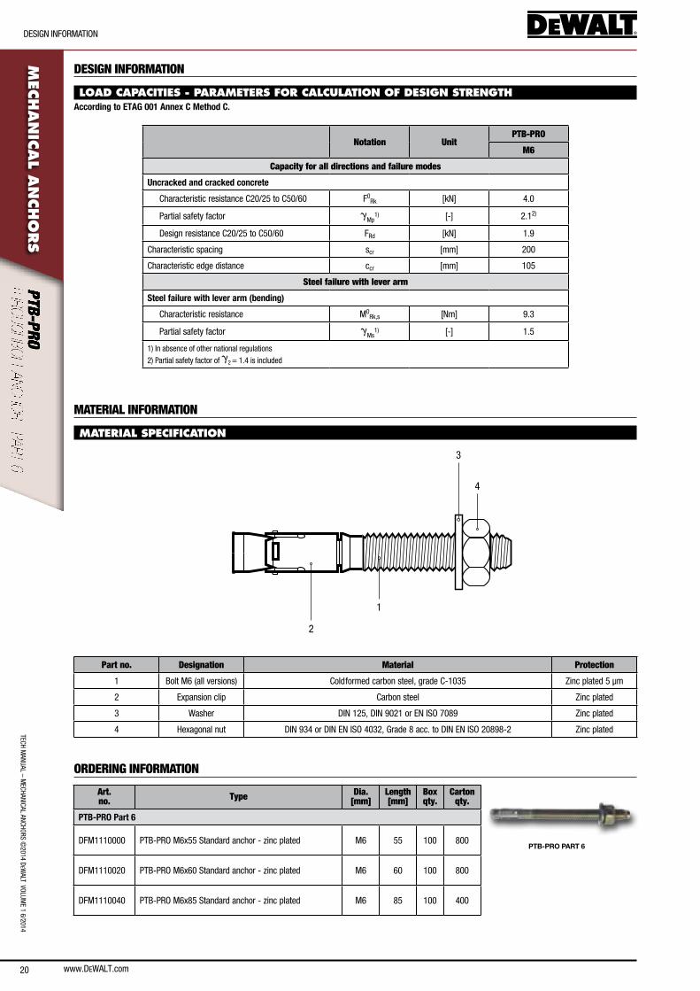
MATERIAL SPECIFICATION
4
3
1
2
Part no. Designation Material Protection
1 bolt M6 (all versions) cold formed carbon steel, grade c-1035 Zinc plated 5 µm
2 expansion clip carbon steel Zinc plated
3 Washer DIn 125, DIn 9021 or en Iso 7089 Zinc plated
4 Hexagonal nut DIn 934 or DIn en Iso 4032, Grade 8 acc. to DIn en Iso 20898-2 Zinc plated
ORDERING INFORMATION
Art. no. Type Dia.
[mm]Length [mm]
Box qty.
Carton qty.
PTB-PRO PART 6
PTB-PRO Part 6
DfM1110000 PTb-PRo M6x55 standard anchor - zinc plated M6 55 100 800
DfM1110020 PTb-PRo M6x60 standard anchor - zinc plated M6 60 100 800
DfM1110040 PTb-PRo M6x85 standard anchor - zinc plated M6 85 100 400
www.DEWALT.com 21
TecH
Man
Ual
– M
ecHa
nIca
l an
cHoR
s ©
2014
DeW
alT
Vol
UMe
1 6/
2014
GeneRal InfoRMaTIon
MEC
HAN
ICAL
AN
CHO
RSSECTION CONTENTS
General Information
Installation Information
Design Information
Material Information
ordering Information
ASSEMBLY
Hexagon nut
Washer
bolt
clip
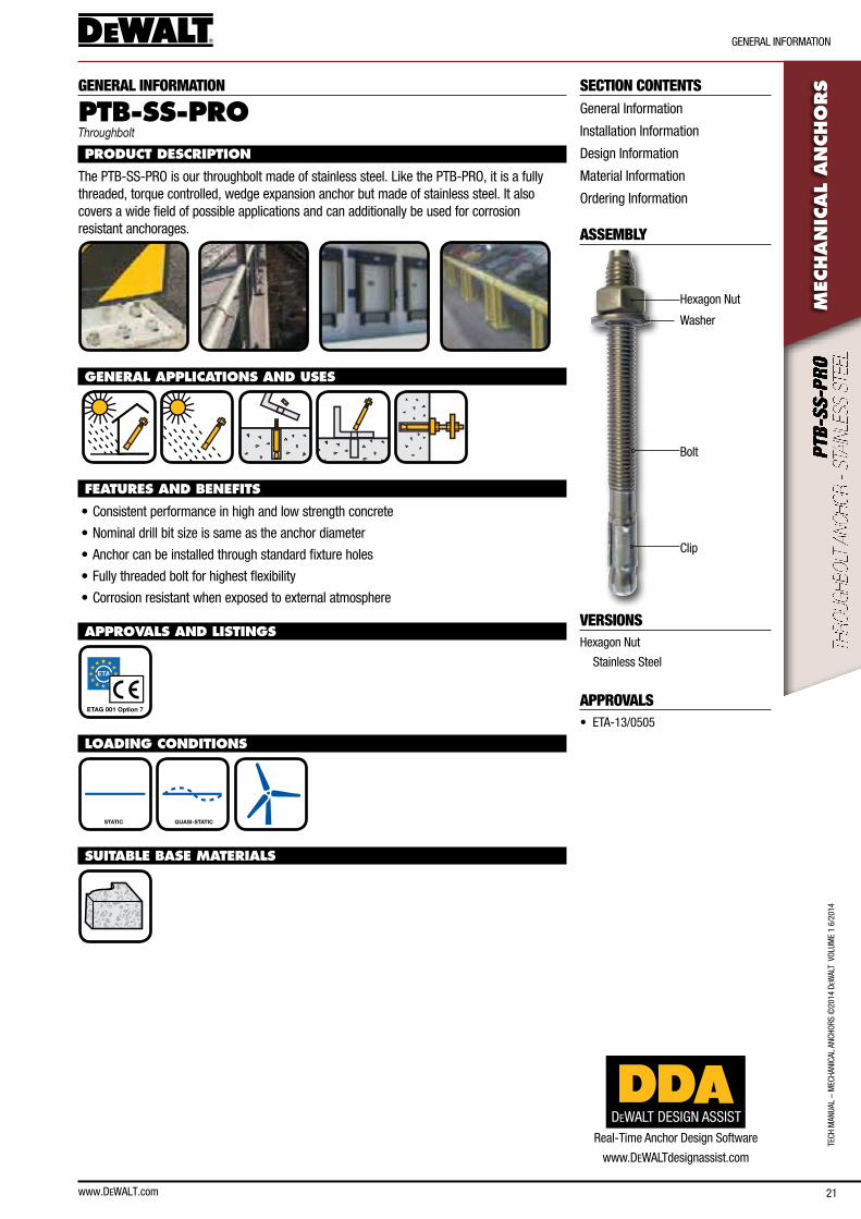
VERSIONSHexagon nut
stainless steel
APPROVALS• eTa-13/0505
GENERAL INFORMATION
PTB-SS-PRO Throughbolt
PRODUCT DESCRIPTION
The PTb-ss-PRo is our throughbolt made of stainless steel. like the PTb-PRo, it is a fully threaded, torque controlled, wedge expansion anchor but made of stainless steel. It also covers a wide field of possible applications and can additionally be used for corrosion resistant anchorages.
GENERAL APPLICATIONS AND USES
FEATURES AND BENEFITS
• consistent performance in high and low strength concrete
• nominal drill bit size is same as the anchor diameter
• anchor can be installed through standard fixture holes
• fully threaded bolt for highest flexibility
• corrosion resistant when exposed to external atmosphere
APPROVALS AND LISTINGS
ETAG 001 Option 7 O
LOADING CONDITIONS
STATIC QUASI-STATIC
SUITABLE BASE MATERIALS
DEWALT DESIGN ASSISTReal-Time anchor Design software
www.DeWalTdesignassist.com
www.DEWALT.com22
InsTallaTIon InfoRMaTIon
TecH ManUal – M
ecHanIcal ancHoRs ©2014 D
eWalT VolUM
e 1 6/2014M
ECHAN
ICAL A
NCHO
RS
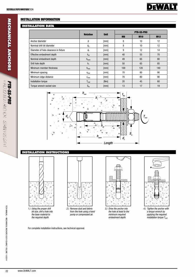
INSTALLATION INFORMATION
INSTALLATION DATA
Notation UnitPTB-SS-PRO
M8 M10 M12
anchor diameter d [mm] 8 10 12
nominal drill bit diameter d0 [mm] 8 10 12
Diameter of hole clearance in fixture df [mm] 9 12 14
effective embedment depth hef [mm] 40 55 70
nominal embedment depth hnom [mm] 49 65 80
Drill hole depth h1 [mm] 50 65 85
Minimum member thickness hmin [mm] 100 120 140
Minimum spacing smin [mm] 70 80 90
Minimum edge distance cmin [mm] 70 80 90
Installation torque Tinst [nm] 20 45 60
Torque wrench socket size sw [mm] 13 17 19
hmin
hef
d0
df
Sw
tfix
Tinst
h1
Length
hnom
INSTALLATION INSTRUCTIONS
1.) Using the proper drill bit size, drill a hole into the base material to the required depth.
2.) Remove dust and debris from the hole using a hand pump or compressed air.
3.) Drive the anchor into the hole at least to the minimum required embedment depth.
4.) Tighten the anchor with a torque wrench by applying the required installation torque Tinst.
for complete installation instructions, see technical approval.
GeneRal InfoRMaTIon
www.DEWALT.com 23
TecH
Man
Ual
– M
ecHa
nIca
l an
cHoR
s ©
2014
DeW
alT
Vol
UMe
1 6/
2014
DesIGn InfoRMaTIon
MEC
HAN
ICAL
AN
CHO
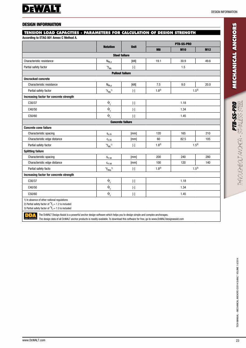
RSDESIGN INFORMATION
TENSION LOAD CAPACITIES - PARAMETERS FOR CALCULATION OF DESIGN STRENGTHAccording to ETAG 001 Annex C Method A.
Notation UnitPTB-SS-PRO
M8 M10 M12
Steel failure
characteristic resistance nRk,s [kn] 19.1 30.9 49.6
Partial safety factor gMs [-] 1.5
Pullout failure
Uncracked concrete
characteristic resistance nRk,p [kn] 7.5 9.0 20.0
Partial safety factor gMp
1) [-] 1.82) 1.53)
Increasing factor for concrete strength
c30/37 cc [-] 1.18
c40/50 cc [-] 1.34
c50/60 cc [-] 1.45
Concrete failure
Concrete cone failure
characteristic spacing scr,n [mm] 120 165 210
characteristic edge distance ccr,n [mm] 60 82.5 105
Partial safety factor gMc
1) [-] 1.82) 1.53)
Splitting failure
characteristic spacing scr,sp [mm] 200 240 280
characteristic edge distance ccr,sp [mm] 100 120 140
Partial safety facto gMsp
1) [-] 1.82) 1.53)
Increasing factor for concrete strength
c30/37 cc [-] 1.18
c40/50 cc [-] 1.34
c50/60 cc [-] 1.45
1) In absence of other national regulations
2) Partial safety factor of g2 = 1.2 is included
3) Partial safety factor of g2 = 1.0 is included
DEWALT DESIGN ASSIST
The DeWalT Design assist is a powerful anchor design software which helps you to design simple and complex anchorages.
The design data of all DeWalT anchor products is readily available. To download this software for free, go to www.DeWalTdesignassist.com
24
TecH ManUal – M
ecHanIcal ancHoRs ©2014 D
eWalT VolUM
e 1 6/2014
DesIGn InfoRMaTIon
www.DEWALT.com
MEC
HAN
ICAL A
NCHO
RS
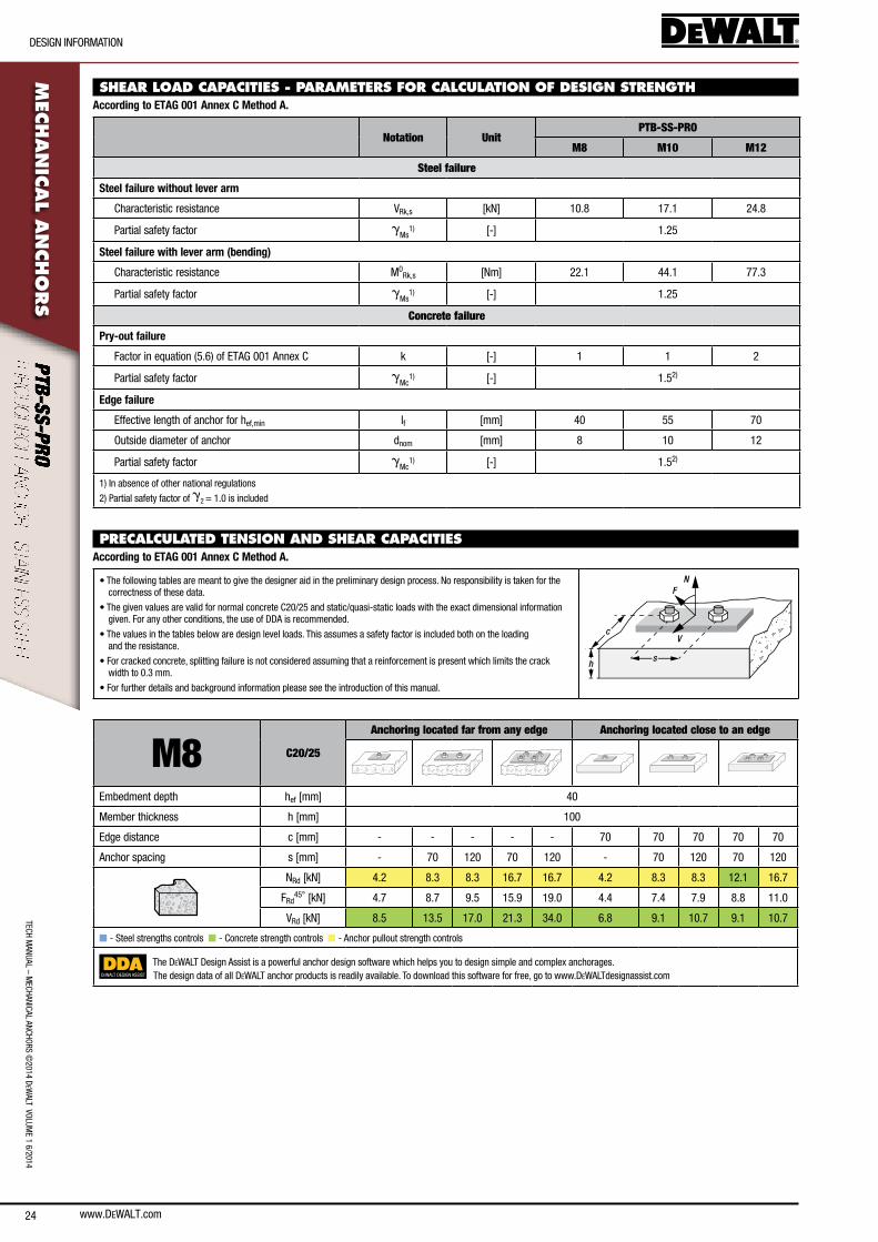
SHEAR LOAD CAPACITIES - PARAMETERS FOR CALCULATION OF DESIGN STRENGTHAccording to ETAG 001 Annex C Method A.
Notation UnitPTB-SS-PRO
M8 M10 M12
Steel failure
Steel failure without lever arm
characteristic resistance VRk,s [kn] 10.8 17.1 24.8
Partial safety factor gMs
1) [-] 1.25
Steel failure with lever arm (bending)
characteristic resistance M0Rk,s [nm] 22.1 44.1 77.3
Partial safety factor gMs
1) [-] 1.25
Concrete failure
Pry-out failure
factor in equation (5.6) of eTaG 001 annex c k [-] 1 1 2
Partial safety factor gMc
1) [-] 1.52)
Edge failure
effective length of anchor for hef,min lf [mm] 40 55 70
outside diameter of anchor dnom [mm] 8 10 12
Partial safety factor gMc
1) [-] 1.52)
1) In absence of other national regulations
2) Partial safety factor of g2 = 1.0 is included
PRECALCULATED TENSION AND SHEAR CAPACITIES According to ETAG 001 Annex C Method A.
• The following tables are meant to give the designer aid in the preliminary design process. no responsibility is taken for the correctness of these data.
• The given values are valid for normal concrete c20/25 and static/quasi-static loads with the exact dimensional information given. for any other conditions, the use of DDa is recommended.
• The values in the tables below are design level loads. This assumes a safety factor is included both on the loading and the resistance.
• for cracked concrete, splitting failure is not considered assuming that a reinforcement is present which limits the crack width to 0.3 mm.
• for further details and background information please see the introduction of this manual.
N
V
F
sh
c
M8 C20/25
Anchoring located far from any edge Anchoring located close to an edge
embedment depth hef [mm] 40
Member thickness h [mm] 100
edge distance c [mm] - - - - - 70 70 70 70 70
anchor spacing s [mm] - 70 120 70 120 - 70 120 70 120
nRd [kn] 4.2 8.3 8.3 16.7 16.7 4.2 8.3 8.3 12.1 16.7
fRd45° [kn] 4.7 8.7 9.5 15.9 19.0 4.4 7.4 7.9 8.8 11.0
VRd [kn] 8.5 13.5 17.0 21.3 34.0 6.8 9.1 10.7 9.1 10.7
n - steel strengths controls n - concrete strength controls n - anchor pullout strength controls
DEWALT DESIGN ASSIST
The DeWalT Design assist is a powerful anchor design software which helps you to design simple and complex anchorages.The design data of all DeWalT anchor products is readily available. To download this software for free, go to www.DeWalTdesignassist.com
www.DEWALT.com 25
TecH
Man
Ual
– M
ecHa
nIca
l an
cHoR
s ©
2014
DeW
alT
Vol
UMe
1 6/
2014
DesIGn InfoRMaTIon
MEC
HAN
ICAL
AN
CHO
RS
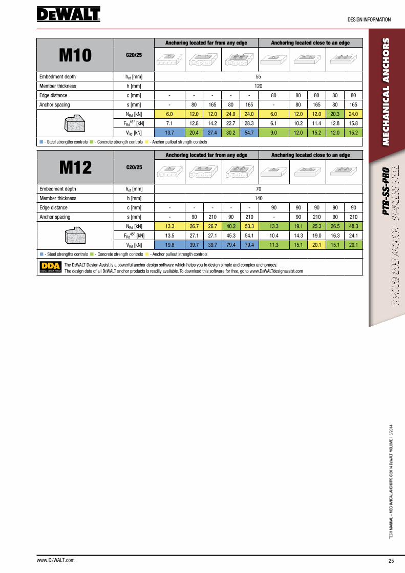
M10 C20/25
Anchoring located far from any edge Anchoring located close to an edge
embedment depth hef [mm] 55
Member thickness h [mm] 120
edge distance c [mm] - - - - - 80 80 80 80 80
anchor spacing s [mm] - 80 165 80 165 - 80 165 80 165
nRd [kn] 6.0 12.0 12.0 24.0 24.0 6.0 12.0 12.0 20.3 24.0
fRd45° [kn] 7.1 12.8 14.2 22.7 28.3 6.1 10.2 11.4 12.8 15.8
VRd [kn] 13.7 20.4 27.4 30.2 54.7 9.0 12.0 15.2 12.0 15.2
n - steel strengths controls n - concrete strength controls n - anchor pullout strength controls
M12 C20/25
Anchoring located far from any edge Anchoring located close to an edge
embedment depth hef [mm] 70
Member thickness h [mm] 140
edge distance c [mm] - - - - - 90 90 90 90 90
anchor spacing s [mm] - 90 210 90 210 - 90 210 90 210
nRd [kn] 13.3 26.7 26.7 40.2 53.3 13.3 19.1 25.3 26.5 48.3
fRd45° [kn] 13.5 27.1 27.1 45.3 54.1 10.4 14.3 19.0 16.3 24.1
VRd [kn] 19.8 39.7 39.7 79.4 79.4 11.3 15.1 20.1 15.1 20.1
n - steel strengths controls n - concrete strength controls n - anchor pullout strength controls
DEWALT DESIGN ASSIST
The DeWalT Design assist is a powerful anchor design software which helps you to design simple and complex anchorages.The design data of all DeWalT anchor products is readily available. To download this software for free, go to www.DeWalTdesignassist.com
26
TecH ManUal – M
ecHanIcal ancHoRs ©2014 D
eWalT VolUM
e 1 6/2014
MaTeRIal InfoRMaTIon
www.DEWALT.com
MEC
HAN
ICAL A
NCHO
RS
MATERIAL INFORMATION
MATERIAL SPECIFICATION
4
3
1
2
Part no. Designation Material Protection
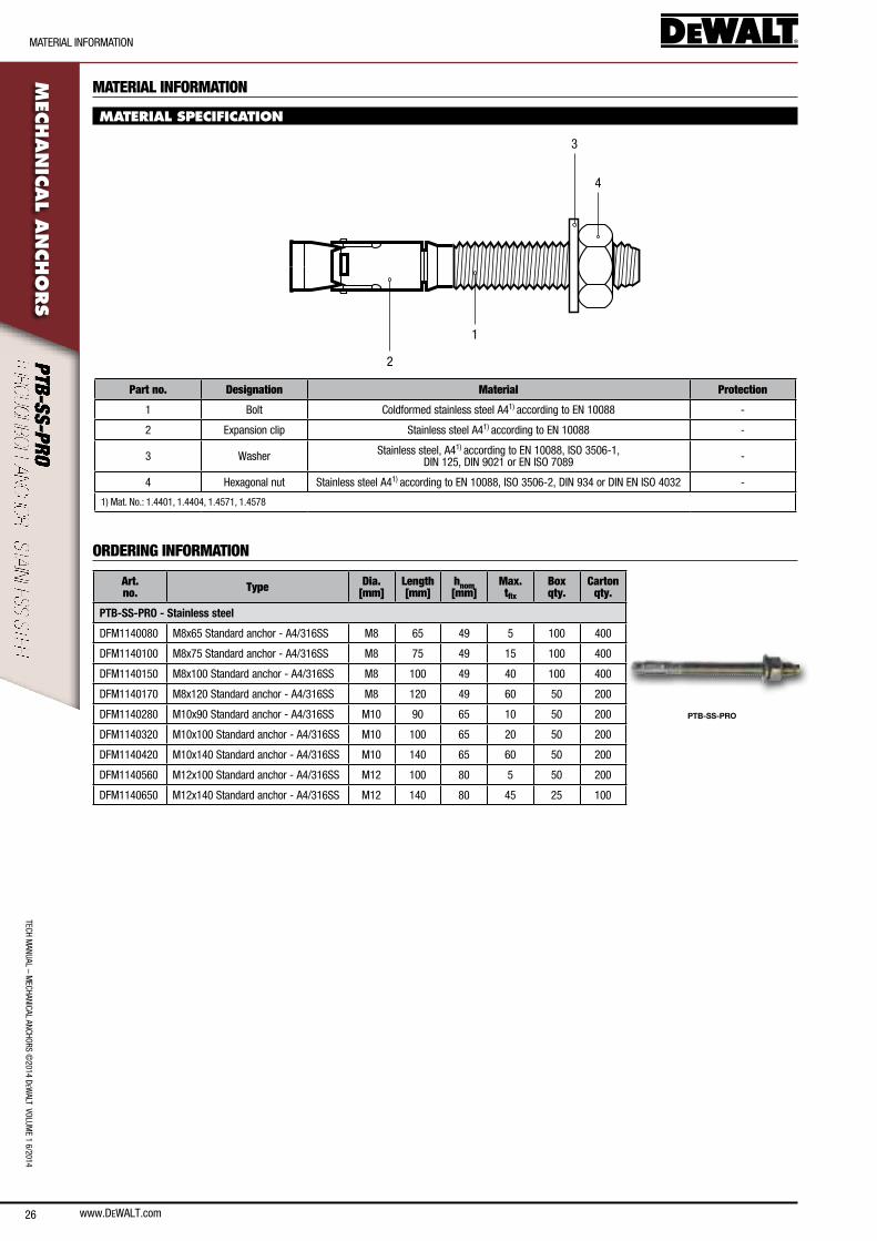
1 bolt coldformed stainless steel a41) according to en 10088 -
2 expansion clip stainless steel a41) according to en 10088 -
3 Washer stainless steel, a41) according to en 10088, Iso 3506-1, DIn 125, DIn 9021 or en Iso 7089 -
4 Hexagonal nut stainless steel a41) according to en 10088, Iso 3506-2, DIn 934 or DIn en Iso 4032 -
1) Mat. no.: 1.4401, 1.4404, 1.4571, 1.4578
ORDERING INFORMATION
Art. no. Type Dia.
[mm]Length [mm]
hnom [mm]
Max. tfix
Box qty.
Carton qty.
PTB-SS-PRO
PTB-SS-PRO - Stainless steel
DfM1140080 M8x65 standard anchor - a4/316ss M8 65 49 5 100 400
DfM1140100 M8x75 standard anchor - a4/316ss M8 75 49 15 100 400
DfM1140150 M8x100 standard anchor - a4/316ss M8 100 49 40 100 400
DfM1140170 M8x120 standard anchor - a4/316ss M8 120 49 60 50 200
DfM1140280 M10x90 standard anchor - a4/316ss M10 90 65 10 50 200
DfM1140320 M10x100 standard anchor - a4/316ss M10 100 65 20 50 200
DfM1140420 M10x140 standard anchor - a4/316ss M10 140 65 60 50 200
DfM1140560 M12x100 standard anchor - a4/316ss M12 100 80 5 50 200
DfM1140650 M12x140 standard anchor - a4/316ss M12 140 80 45 25 100
www.DEWALT.com 27
TecH
Man
Ual
– M
ecHa
nIca
l an
cHoR
s ©
2014
DeW
alT
Vol
UMe
1 6/
2014
GeneRal InfoRMaTIon
MEC
HAN
ICAL
AN
CHO
RSSECTION CONTENTS
General Information
Installation Information
Design Information
Material Information
ordering Information
ASSEMBLY
VERSIONSstraight collar
carbon steel, Zinc Plated
stainless steel
lipped collar
carbon steel, Zinc Plated
APPROVALS• eTa-13/0057
GENERAL INFORMATION
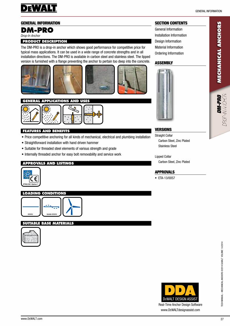
DM-PRO Drop-In Anchor
PRODUCT DESCRIPTION
The DM-PRo is a drop-in anchor which shows good performance for competitive price for typical mass applications. It can be used in a wide range of concrete strengths and in all installation directions. The DM-PRo is available in carbon steel and stainless steel. The lipped version is furnished with a flange preventing the anchor to pertain too deep into the concrete.
GENERAL APPLICATIONS AND USES
FEATURES AND BENEFITS
• Price competitive anchoring for all kinds of mechanical, electrical and plumbing installation
• straightforward installation with hand driven hammer
• suitable for threaded steel elements of various strength and grade
• Internally threaded anchor for easy bolt removability and service work
APPROVALS AND LISTINGS
ETAG 001 Option 7
LOADING CONDITIONS
STATIC QUASI-STATIC
SUITABLE BASE MATERIALS
DEWALT DESIGN ASSISTReal-Time anchor Design software
www.DeWalTdesignassist.com
www.DEWALT.com28
InsTallaTIon InfoRMaTIon
TecH ManUal – M
ecHanIcal ancHoRs ©2014 D
eWalT VolUM
e 1 6/2014M
ECHAN
ICAL A
NCHO
RS
INSTALLATION INFORMATION
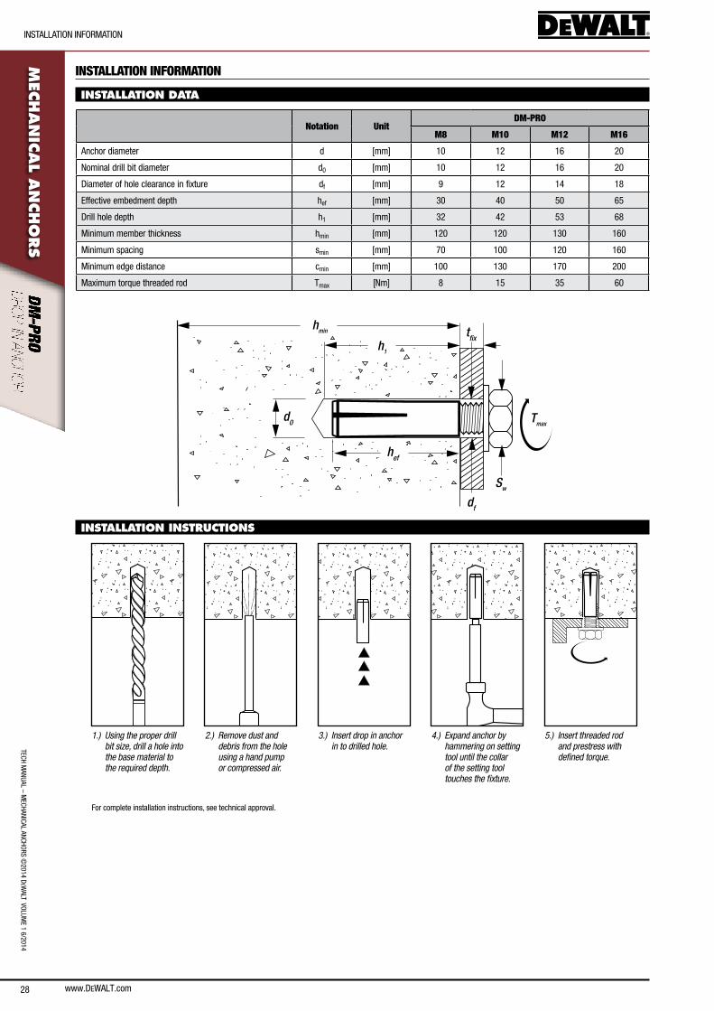
INSTALLATION DATA
Notation UnitDM-PRO
M8 M10 M12 M16
anchor diameter d [mm] 10 12 16 20
nominal drill bit diameter d0 [mm] 10 12 16 20
Diameter of hole clearance in fixture df [mm] 9 12 14 18
effective embedment depth hef [mm] 30 40 50 65
Drill hole depth h1 [mm] 32 42 53 68
Minimum member thickness hmin [mm] 120 120 130 160
Minimum spacing smin [mm] 70 100 120 160
Minimum edge distance cmin [mm] 100 130 170 200
Maximum torque threaded rod Tmax [nm] 8 15 35 60
hmin
hef
d0
df
Sw
Tmax
h1
tfix
INSTALLATION INSTRUCTIONS
1.) Using the proper drill bit size, drill a hole into the base material to the required depth.
2.) Remove dust and debris from the hole using a hand pump or compressed air.
3.) Insert drop in anchor in to drilled hole.
4.) Expand anchor by hammering on setting tool until the collar of the setting tool touches the fixture.
5.) Insert threaded rod and prestress with defined torque.
for complete installation instructions, see technical approval.
www.DEWALT.com 29
TecH
Man
Ual
– M
ecHa
nIca
l an
cHoR
s ©
2014
DeW
alT
Vol
UMe
1 6/
2014
DesIGn InfoRMaTIon
MEC
HAN
ICAL
AN
CHO
RSDESIGN INFORMATION
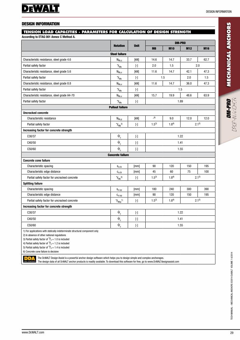
TENSION LOAD CAPACITIES - PARAMETERS FOR CALCULATION OF DESIGN STRENGTHAccording to ETAG 001 Annex C Method A.
Notation UnitDM-PRO
M8 M10 M12 M16
Steel failure
characteristic resistance, steel grade 4.6 nRk,s [kn] 14.6 14.7 33.7 62.7
Partial safety factor gMs [-] 2.0 1.5 2.0
characteristic resistance, steel grade 5.6 nRk,s [kn] 11.6 14.7 42.1 47.3
Partial safety factor gMs [-] 1.5 2.0 1.5
characteristic resistance, steel grade 8.8 nRk,s [kn] 11.6 14.7 36.0 47.3
Partial safety factor gMs [-] 1.5
characteristic resistance, steel grade a4-70 nRk,s [kn] 15.7 19.9 48.6 63.9
Partial safety factor gMs [-] 1.89
Pullout failure
Uncracked concrete
characteristic resistance nRk,p [kn] -6) 9.0 12.0 12.0
Partial safety factor gMp
2) [-] 1.53) 1.84) 2.15)
Increasing factor for concrete strength
c30/37 cc [-] 1.22
c40/50 cc [-] 1.41
c50/60 cc [-] 1.55
Concrete failure
Concrete cone failure
characteristic spacing scr,n [mm] 90 120 150 195
characteristic edge distance ccr,n [mm] 45 60 75 100
Partial safety factor for uncracked concrete gMc
2) [-] 1.53) 1.84) 2.15)
Splitting failure
characteristic spacing scr,sp [mm] 180 240 300 390
characteristic edge distance ccr,sp [mm] 90 120 150 195
Partial safety factor for uncracked concrete gMsp
1) [-] 1.53) 1.84) 2.15)
Increasing factor for concrete strength
c30/37 cc [-] 1.22
c40/50 cc [-] 1.41
c50/60 cc [-] 1.55
1) for applications with statically indeterminate structural component only
2) In absence of other national regulations
3) Partial safety factor of g2 = 1.0 is included
4) Partial safety factor of g2 = 1.2 is included
5) Partial safety factor of g2 = 1.4 is included
6) concrete cone failure is decisive
DEWALT DESIGN ASSIST
The DeWalT Design assist is a powerful anchor design software which helps you to design simple and complex anchorages.The design data of all DeWalT anchor products is readily available. To download this software for free, go to www.DeWalTdesignassist.com
30
TecH ManUal – M
ecHanIcal ancHoRs ©2014 D
eWalT VolUM
e 1 6/2014
DesIGn InfoRMaTIon
www.DEWALT.com
MEC
HAN
ICAL A
NCHO
RS
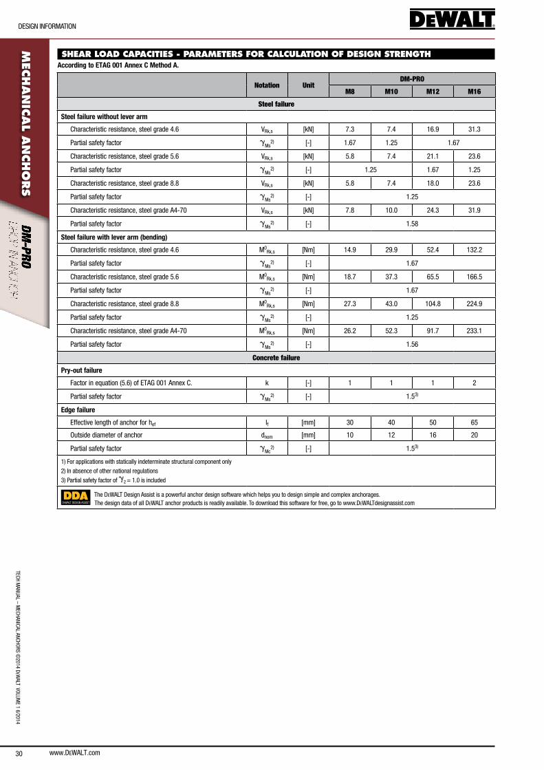
SHEAR LOAD CAPACITIES - PARAMETERS FOR CALCULATION OF DESIGN STRENGTHAccording to ETAG 001 Annex C Method A.
Notation UnitDM-PRO
M8 M10 M12 M16
Steel failure
Steel failure without lever arm
characteristic resistance, steel grade 4.6 VRk,s [kn] 7.3 7.4 16.9 31.3
Partial safety factor gMs
2) [-] 1.67 1.25 1.67
characteristic resistance, steel grade 5.6 VRk,s [kn] 5.8 7.4 21.1 23.6
Partial safety factor gMs
2) [-] 1.25 1.67 1.25
characteristic resistance, steel grade 8.8 VRk,s [kn] 5.8 7.4 18.0 23.6
Partial safety factor gMs
2) [-] 1.25
characteristic resistance, steel grade a4-70 VRk,s [kn] 7.8 10.0 24.3 31.9
Partial safety factor gMs
2) [-] 1.58
Steel failure with lever arm (bending)
characteristic resistance, steel grade 4.6 M0Rk,s [nm] 14.9 29.9 52.4 132.2
Partial safety factor gMs
2) [-] 1.67
characteristic resistance, steel grade 5.6 M0Rk,s [nm] 18.7 37.3 65.5 166.5
Partial safety factor gMs
2) [-] 1.67
characteristic resistance, steel grade 8.8 M0Rk,s [nm] 27.3 43.0 104.8 224.9
Partial safety factor gMs
2) [-] 1.25
characteristic resistance, steel grade a4-70 M0Rk,s [nm] 26.2 52.3 91.7 233.1
Partial safety factor gMs
2) [-] 1.56
Concrete failure
Pry-out failure
factor in equation (5.6) of eTaG 001 annex c. k [-] 1 1 1 2
Partial safety factor gMs
2) [-] 1.53)
Edge failure
effective length of anchor for hef lf [mm] 30 40 50 65
outside diameter of anchor dnom [mm] 10 12 16 20
Partial safety factor gMc
2) [-] 1.53)
1) for applications with statically indeterminate structural component only
2) In absence of other national regulations
3) Partial safety factor of g2 = 1.0 is included
DEWALT DESIGN ASSIST
The DeWalT Design assist is a powerful anchor design software which helps you to design simple and complex anchorages.The design data of all DeWalT anchor products is readily available. To download this software for free, go to www.DeWalTdesignassist.com
www.DEWALT.com 31
TecH
Man
Ual
– M
ecHa
nIca
l an
cHoR
s ©
2014
DeW
alT
Vol
UMe
1 6/
2014
DesIGn InfoRMaTIon
MEC
HAN
ICAL
AN
CHO
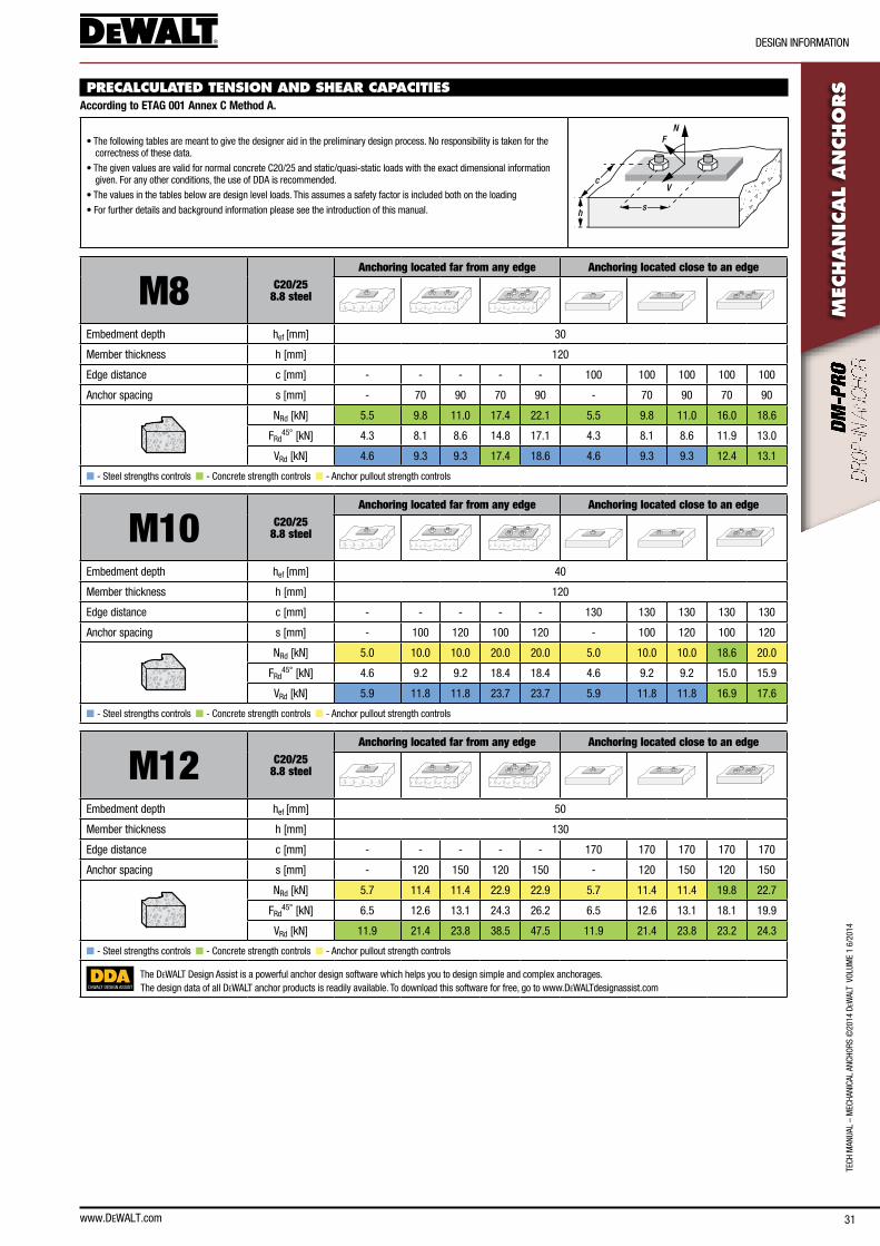
RSPRECALCULATED TENSION AND SHEAR CAPACITIES
According to ETAG 001 Annex C Method A.
• The following tables are meant to give the designer aid in the preliminary design process. no responsibility is taken for the correctness of these data.
• The given values are valid for normal concrete c20/25 and static/quasi-static loads with the exact dimensional information given. for any other conditions, the use of DDa is recommended.
• The values in the tables below are design level loads. This assumes a safety factor is included both on the loading
• for further details and background information please see the introduction of this manual.
N
V
F
sh
c
M8 C20/258.8 steel
Anchoring located far from any edge Anchoring located close to an edge
embedment depth hef [mm] 30
Member thickness h [mm] 120
edge distance c [mm] - - - - - 100 100 100 100 100
anchor spacing s [mm] - 70 90 70 90 - 70 90 70 90
nRd [kn] 5.5 9.8 11.0 17.4 22.1 5.5 9.8 11.0 16.0 18.6
fRd45° [kn] 4.3 8.1 8.6 14.8 17.1 4.3 8.1 8.6 11.9 13.0
VRd [kn] 4.6 9.3 9.3 17.4 18.6 4.6 9.3 9.3 12.4 13.1
n - steel strengths controls n - concrete strength controls n - anchor pullout strength controls
M10 C20/258.8 steel
Anchoring located far from any edge Anchoring located close to an edge
embedment depth hef [mm] 40
Member thickness h [mm] 120
edge distance c [mm] - - - - - 130 130 130 130 130
anchor spacing s [mm] - 100 120 100 120 - 100 120 100 120
nRd [kn] 5.0 10.0 10.0 20.0 20.0 5.0 10.0 10.0 18.6 20.0
fRd45° [kn] 4.6 9.2 9.2 18.4 18.4 4.6 9.2 9.2 15.0 15.9
VRd [kn] 5.9 11.8 11.8 23.7 23.7 5.9 11.8 11.8 16.9 17.6
n - steel strengths controls n - concrete strength controls n - anchor pullout strength controls
M12 C20/258.8 steel
Anchoring located far from any edge Anchoring located close to an edge
embedment depth hef [mm] 50
Member thickness h [mm] 130
edge distance c [mm] - - - - - 170 170 170 170 170
anchor spacing s [mm] - 120 150 120 150 - 120 150 120 150
nRd [kn] 5.7 11.4 11.4 22.9 22.9 5.7 11.4 11.4 19.8 22.7
fRd45° [kn] 6.5 12.6 13.1 24.3 26.2 6.5 12.6 13.1 18.1 19.9
VRd [kn] 11.9 21.4 23.8 38.5 47.5 11.9 21.4 23.8 23.2 24.3
n - steel strengths controls n - concrete strength controls n - anchor pullout strength controls
DEWALT DESIGN ASSIST
The DeWalT Design assist is a powerful anchor design software which helps you to design simple and complex anchorages.The design data of all DeWalT anchor products is readily available. To download this software for free, go to www.DeWalTdesignassist.com
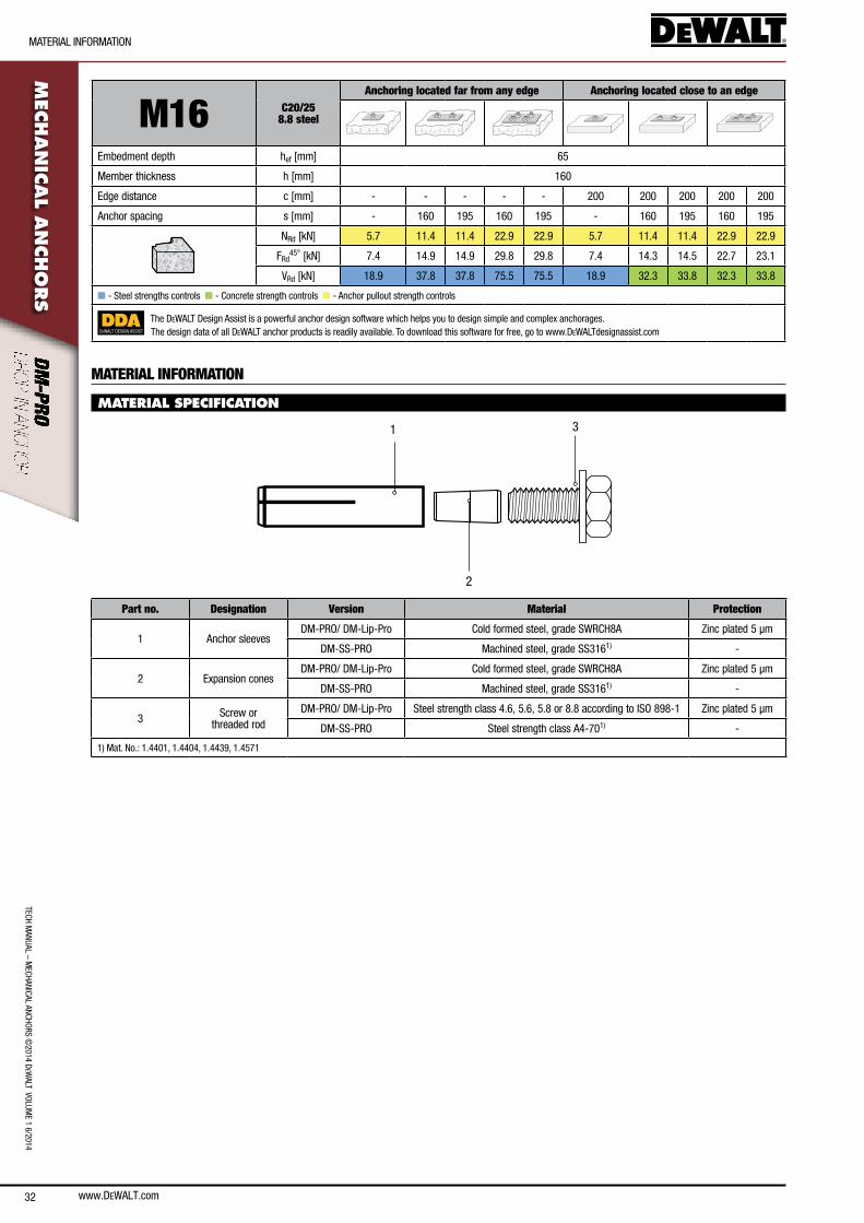
32
TecH ManUal – M
ecHanIcal ancHoRs ©2014 D
eWalT VolUM
e 1 6/2014
MaTeRIal InfoRMaTIon
www.DEWALT.com
MEC
HAN
ICAL A
NCHO
RS
M16 C20/258.8 steel
Anchoring located far from any edge Anchoring located close to an edge
embedment depth hef [mm] 65
Member thickness h [mm] 160
edge distance c [mm] - - - - - 200 200 200 200 200
anchor spacing s [mm] - 160 195 160 195 - 160 195 160 195
nRd [kn] 5.7 11.4 11.4 22.9 22.9 5.7 11.4 11.4 22.9 22.9
fRd45° [kn] 7.4 14.9 14.9 29.8 29.8 7.4 14.3 14.5 22.7 23.1
VRd [kn] 18.9 37.8 37.8 75.5 75.5 18.9 32.3 33.8 32.3 33.8
n - steel strengths controls n - concrete strength controls n - anchor pullout strength controls
DEWALT DESIGN ASSIST
The DeWalT Design assist is a powerful anchor design software which helps you to design simple and complex anchorages.The design data of all DeWalT anchor products is readily available. To download this software for free, go to www.DeWalTdesignassist.com
MATERIAL INFORMATION
MATERIAL SPECIFICATION
31
2
Part no. Designation Version Material Protection
1 anchor sleevesDM-PRo/ DM-lip-Pro cold formed steel, grade sWRcH8a Zinc plated 5 µm
DM-ss-PRo Machined steel, grade ss3161) -
2 expansion conesDM-PRo/ DM-lip-Pro cold formed steel, grade sWRcH8a Zinc plated 5 µm
DM-ss-PRo Machined steel, grade ss3161) -
3 screw or threaded rod
DM-PRo/ DM-lip-Pro steel strength class 4.6, 5.6, 5.8 or 8.8 according to Iso 898-1 Zinc plated 5 µm
DM-ss-PRo steel strength class a4-701) -
1) Mat. no.: 1.4401, 1.4404, 1.4439, 1.4571
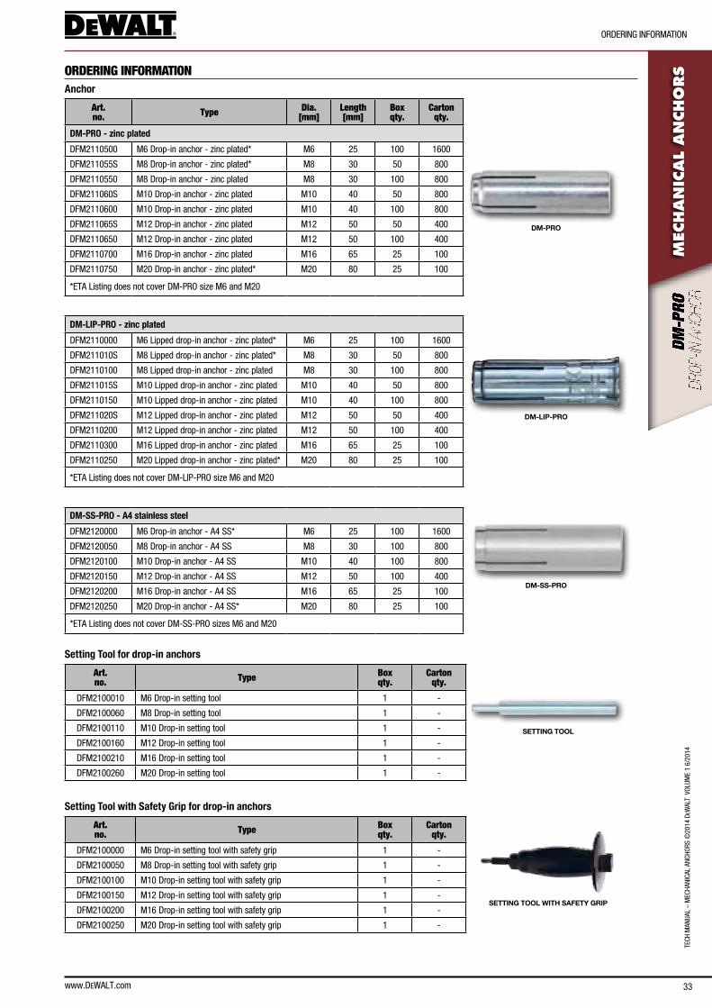
www.DEWALT.com 33
TecH
Man
Ual
– M
ecHa
nIca
l an
cHoR
s ©
2014
DeW
alT
Vol
UMe
1 6/
2014
oRDeRInG InfoRMaTIon
MEC
HAN
ICAL
AN
CHO
RSORDERING INFORMATION
Anchor
Art. no. Type Dia.
[mm]Length [mm]
Box qty.
Carton qty.
DM-PRO
DM-PRO - zinc plated
DfM2110500 M6 Drop-in anchor - zinc plated* M6 25 100 1600
DfM211055s M8 Drop-in anchor - zinc plated* M8 30 50 800
DfM2110550 M8 Drop-in anchor - zinc plated M8 30 100 800
DfM211060s M10 Drop-in anchor - zinc plated M10 40 50 800
DfM2110600 M10 Drop-in anchor - zinc plated M10 40 100 800
DfM211065s M12 Drop-in anchor - zinc plated M12 50 50 400
DfM2110650 M12 Drop-in anchor - zinc plated M12 50 100 400
DfM2110700 M16 Drop-in anchor - zinc plated M16 65 25 100
DfM2110750 M20 Drop-in anchor - zinc plated* M20 80 25 100
*eTa listing does not cover DM-PRo size M6 and M20
DM-LIP-PRO - zinc plated
DM-LIP-PRO
DfM2110000 M6 lipped drop-in anchor - zinc plated* M6 25 100 1600
DfM211010s M8 lipped drop-in anchor - zinc plated* M8 30 50 800
DfM2110100 M8 lipped drop-in anchor - zinc plated M8 30 100 800
DfM211015s M10 lipped drop-in anchor - zinc plated M10 40 50 800
DfM2110150 M10 lipped drop-in anchor - zinc plated M10 40 100 800
DfM211020s M12 lipped drop-in anchor - zinc plated M12 50 50 400
DfM2110200 M12 lipped drop-in anchor - zinc plated M12 50 100 400
DfM2110300 M16 lipped drop-in anchor - zinc plated M16 65 25 100
DfM2110250 M20 lipped drop-in anchor - zinc plated* M20 80 25 100
*eTa listing does not cover DM-lIP-PRo size M6 and M20
DM-SS-PRO - A4 stainless steel
DM-SS-PRO
DfM2120000 M6 Drop-in anchor - a4 ss* M6 25 100 1600
DfM2120050 M8 Drop-in anchor - a4 ss M8 30 100 800
DfM2120100 M10 Drop-in anchor - a4 ss M10 40 100 800
DfM2120150 M12 Drop-in anchor - a4 ss M12 50 100 400
DfM2120200 M16 Drop-in anchor - a4 ss M16 65 25 100
DfM2120250 M20 Drop-in anchor - a4 ss* M20 80 25 100
*eTa listing does not cover DM-ss-PRo sizes M6 and M20
Setting Tool for drop-in anchors
Art. no. Type Box
qty. Carton
qty.
SETTING TOOL
DfM2100010 M6 Drop-in setting tool 1 -
DfM2100060 M8 Drop-in setting tool 1 -
DfM2100110 M10 Drop-in setting tool 1 -
DfM2100160 M12 Drop-in setting tool 1 -
DfM2100210 M16 Drop-in setting tool 1 -
DfM2100260 M20 Drop-in setting tool 1 -
Setting Tool with Safety Grip for drop-in anchors
Art. no. Type Box
qty. Carton
qty.
SETTING TOOL WITH SAFETY GRIP
DfM2100000 M6 Drop-in setting tool with safety grip 1 -
DfM2100050 M8 Drop-in setting tool with safety grip 1 -
DfM2100100 M10 Drop-in setting tool with safety grip 1 -
DfM2100150 M12 Drop-in setting tool with safety grip 1 -
DfM2100200 M16 Drop-in setting tool with safety grip 1 -
DfM2100250 M20 Drop-in setting tool with safety grip 1 -
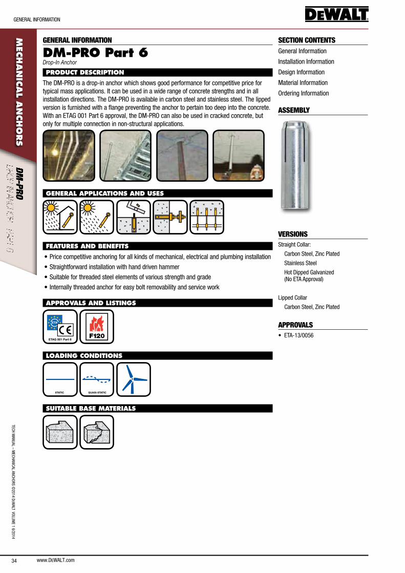
34
TecH ManUal – M
ecHanIcal ancHoRs ©2014 D
eWalT VolUM
e 1 6/2014
GeneRal InfoRMaTIon
www.DEWALT.com
MEC
HAN
ICAL A
NCHO
RS
SECTION CONTENTSGeneral Information
Installation Information
Design Information
Material Information
ordering Information
ASSEMBLY
VERSIONSstraight collar:
carbon steel, Zinc Plated
stainless steel
Hot Dipped Galvanized (no eTa approval)
lipped collar
carbon steel, Zinc Plated
APPROVALS• eTa-13/0056
GENERAL INFORMATION
DM-PRO Part 6Drop-In Anchor
PRODUCT DESCRIPTION
The DM-PRo is a drop-in anchor which shows good performance for competitive price for typical mass applications. It can be used in a wide range of concrete strengths and in all installation directions. The DM-PRo is available in carbon steel and stainless steel. The lipped version is furnished with a flange preventing the anchor to pertain too deep into the concrete. With an eTaG 001 Part 6 approval, the DM-PRo can also be used in cracked concrete, but only for multiple connection in non-structural applications.
GENERAL APPLICATIONS AND USES
FEATURES AND BENEFITS
• Price competitive anchoring for all kinds of mechanical, electrical and plumbing installation
• straightforward installation with hand driven hammer
• suitable for threaded steel elements of various strength and grade
• Internally threaded anchor for easy bolt removability and service work
APPROVALS AND LISTINGS
ETAG 001 Part 6 F120
LOADING CONDITIONS
STATIC QUASI-STATIC
SUITABLE BASE MATERIALS

www.DEWALT.com 35
InsTallaTIon InfoRMaTIon
TecH
Man
Ual
– M
ecHa
nIca
l an
cHoR
s ©
2014
DeW
alT
Vol
UMe
1 6/
2014
MEC
HAN
ICAL
AN
CHO
RSINSTALLATION INFORMATION
INSTALLATION DATA
Notation UnitDM-PRO Part 6
M6 M8 M10 M12
anchor diameter d [mm] 8 10 12 16
nominal drill bit diameter d0 [mm] 8 10 12 16
Diameter of hole clearance in fixture df [mm] 7 9 12 14
effective embedment depth hef [mm] 25 30 40 50
Drill hole depth h1 [mm] 26 32 42 43
Minimum member thickness hmin [mm] 80 80 80 100
Minimum spacing smin [mm] 150 150 150 150
Minimum edge distance cmin [mm] 200 200 200 200
Maximum torque threaded rod Tmax [nm] 4 8 15 35
hmin
hef
d0
df
Sw
Tmax
h1
tfix
INSTALLATION INSTRUCTIONS
1.) Using the proper drill bit size, drill a hole into the base material to the required depth.
2.) Remove dust and debris from the hole using a hand pump or compressed air.
3.) Insert drop in anchor in to drilled hole.
4.) Expand anchor by hammering on setting tool until the collar of the setting tool touches the fixture.
5.) Insert threaded rod and prestress with defined torque.
for complete installation instructions, see technical approval.
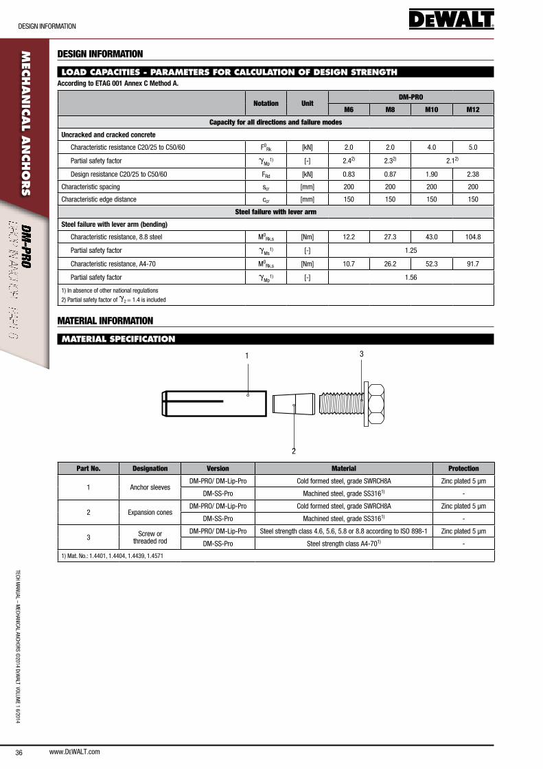
36
DesIGn InfoRMaTIon
TecH ManUal – M
ecHanIcal ancHoRs ©2014 D
eWalT VolUM
e 1 6/2014M
ECHAN
ICAL A
NCHO
RS
www.DeWalT.com
DESIGN INFORMATION
LOAD CAPACITIES - PARAMETERS FOR CALCULATION OF DESIGN STRENGTHAccording to ETAG 001 Annex C Method A.
Notation UnitDM-PRO
M6 M8 M10 M12
Capacity for all directions and failure modes
Uncracked and cracked concrete
characteristic resistance c20/25 to c50/60 f0Rk [kn] 2.0 2.0 4.0 5.0
Partial safety factor gMp
1) [-] 2.42) 2.32) 2.12)
Design resistance c20/25 to c50/60 fRd [kn] 0.83 0.87 1.90 2.38
characteristic spacing scr [mm] 200 200 200 200
characteristic edge distance ccr [mm] 150 150 150 150
Steel failure with lever arm
Steel failure with lever arm (bending)
characteristic resistance, 8.8 steel M0Rk,s [nm] 12.2 27.3 43.0 104.8
Partial safety factor gMs
1) [-] 1.25
characteristic resistance, a4-70 M0Rk,s [nm] 10.7 26.2 52.3 91.7
Partial safety factor gMp
1) [-] 1.56
1) In absence of other national regulations
2) Partial safety factor of g2 = 1.4 is included
MATERIAL INFORMATION
MATERIAL SPECIFICATION
31
2
Part No. Designation Version Material Protection
1 anchor sleevesDM-PRo/ DM-lip-Pro cold formed steel, grade sWRcH8a Zinc plated 5 µm
DM-ss-Pro Machined steel, grade ss3161) -
2 expansion conesDM-PRo/ DM-lip-Pro cold formed steel, grade sWRcH8a Zinc plated 5 µm
DM-ss-Pro Machined steel, grade ss3161) -
3 screw or threaded rod
DM-PRo/ DM-lip-Pro steel strength class 4.6, 5.6, 5.8 or 8.8 according to Iso 898-1 Zinc plated 5 µm
DM-ss-Pro steel strength class a4-701) -
1) Mat. no.: 1.4401, 1.4404, 1.4439, 1.4571
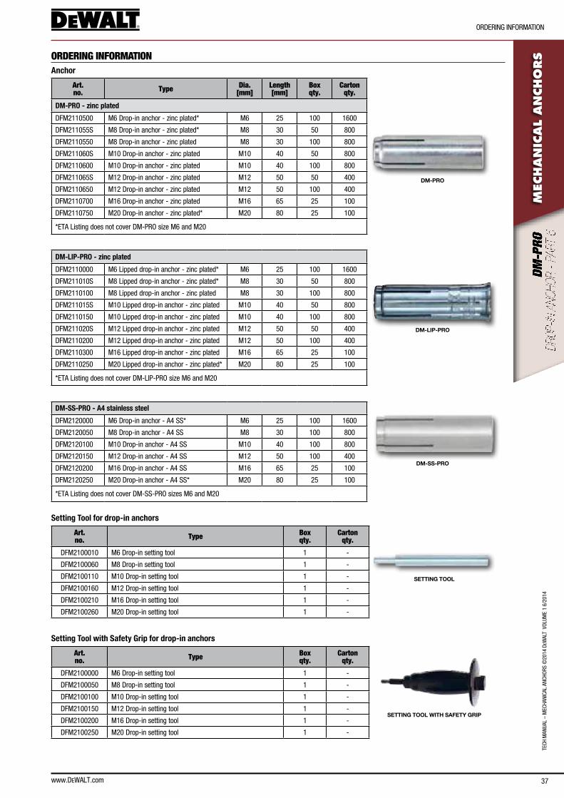
www.DEWALT.com 37
TecH
Man
Ual
– M
ecHa
nIca
l an
cHoR
s ©
2014
DeW
alT
Vol
UMe
1 6/
2014
oRDeRInG InfoRMaTIon
MEC
HAN
ICAL
AN
CHO
RSORDERING INFORMATION
Anchor
Art. no. Type Dia.
[mm]Length [mm]
Box qty.
Carton qty.
DM-PRO
DM-PRO - zinc plated
DfM2110500 M6 Drop-in anchor - zinc plated* M6 25 100 1600
DfM211055s M8 Drop-in anchor - zinc plated* M8 30 50 800
DfM2110550 M8 Drop-in anchor - zinc plated M8 30 100 800
DfM211060s M10 Drop-in anchor - zinc plated M10 40 50 800
DfM2110600 M10 Drop-in anchor - zinc plated M10 40 100 800
DfM211065s M12 Drop-in anchor - zinc plated M12 50 50 400
DfM2110650 M12 Drop-in anchor - zinc plated M12 50 100 400
DfM2110700 M16 Drop-in anchor - zinc plated M16 65 25 100
DfM2110750 M20 Drop-in anchor - zinc plated* M20 80 25 100
*eTa listing does not cover DM-PRo size M6 and M20
DM-LIP-PRO - zinc plated
DM-LIP-PRO
DfM2110000 M6 lipped drop-in anchor - zinc plated* M6 25 100 1600
DfM211010s M8 lipped drop-in anchor - zinc plated* M8 30 50 800
DfM2110100 M8 lipped drop-in anchor - zinc plated M8 30 100 800
DfM211015s M10 lipped drop-in anchor - zinc plated M10 40 50 800
DfM2110150 M10 lipped drop-in anchor - zinc plated M10 40 100 800
DfM211020s M12 lipped drop-in anchor - zinc plated M12 50 50 400
DfM2110200 M12 lipped drop-in anchor - zinc plated M12 50 100 400
DfM2110300 M16 lipped drop-in anchor - zinc plated M16 65 25 100
DfM2110250 M20 lipped drop-in anchor - zinc plated* M20 80 25 100
*eTa listing does not cover DM-lIP-PRo size M6 and M20
DM-SS-PRO - A4 stainless steel
DM-SS-PRO
DfM2120000 M6 Drop-in anchor - a4 ss* M6 25 100 1600
DfM2120050 M8 Drop-in anchor - a4 ss M8 30 100 800
DfM2120100 M10 Drop-in anchor - a4 ss M10 40 100 800
DfM2120150 M12 Drop-in anchor - a4 ss M12 50 100 400
DfM2120200 M16 Drop-in anchor - a4 ss M16 65 25 100
DfM2120250 M20 Drop-in anchor - a4 ss* M20 80 25 100
*eTa listing does not cover DM-ss-PRo sizes M6 and M20
Setting Tool for drop-in anchors
Art. no. Type Box
qty. Carton
qty.
SETTING TOOL
DfM2100010 M6 Drop-in setting tool 1 -
DfM2100060 M8 Drop-in setting tool 1 -
DfM2100110 M10 Drop-in setting tool 1 -
DfM2100160 M12 Drop-in setting tool 1 -
DfM2100210 M16 Drop-in setting tool 1 -
DfM2100260 M20 Drop-in setting tool 1 -
Setting Tool with Safety Grip for drop-in anchors
Art. no. Type Box
qty. Carton
qty.
SETTING TOOL WITH SAFETY GRIP
DfM2100000 M6 Drop-in setting tool 1 -
DfM2100050 M8 Drop-in setting tool 1 -
DfM2100100 M10 Drop-in setting tool 1 -
DfM2100150 M12 Drop-in setting tool 1 -
DfM2100200 M16 Drop-in setting tool 1 -
DfM2100250 M20 Drop-in setting tool 1 -

38
TecH ManUal – M
ecHanIcal ancHoRs ©2014 D
eWalT VolUM
e 1 6/2014
GeneRal InfoRMaTIon
www.DEWALT.com
MEC
HAN
ICAL A
NCHO
RS
SECTION CONTENTSGeneral Information
Installation Information
Design Information
Material Information
ordering Information
ASSEMBLY
Hex Head With formed Washer
screw With Dual Thread
Taper Tip
Pan Head
Dome Head
countersunk
VERSIONSHex Head*, Dome Head*, Pan Head* & counter sunk*
carbon steel, Zinc Plated
APPROVALS• eTa-12/0607 (*eTa only valid on
M10, 12 and 16)
GENERAL INFORMATION
BT (BLUE-TIP)Screw Bolt
PRODUCT DESCRIPTION
The blue-Tip is a heavy duty screw anchor with a finished hex head. The one piece design makes it easy to install and the preferred choice for fast, reliable anchoring and is also fully removable. This anchor is designed to resist structural and non-structural loading in cracked and uncracked concrete.
GENERAL APPLICATIONS AND USES
FEATURES AND BENEFITS
• consistent performance in high and low strength concrete
• nominal drill bit size is same as anchor denomination
• Quick and easy installation with a powered impact wrench
• special dust relief thread
• approved for two embedment depths
APPROVALS AND LISTINGS
ETAG 001 Option 1 F120
LOADING CONDITIONS
STATIC QUASI-STATIC
SUITABLE BASE MATERIALS
DEWALT DESIGN ASSISTReal-Time anchor Design software
www.DeWalTdesignassist.com
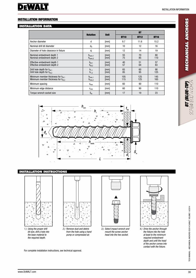
www.DEWALT.com 39
InsTallaTIon InfoRMaTIon
TecH
Man
Ual
– M
ecHa
nIca
l an
cHoR
s ©
2014
DeW
alT
Vol
UMe
1 6/
2014
MEC
HAN
ICAL
AN
CHO
RSINSTALLATION INFORMATION
INSTALLATION DATA
Notation UnitBT
BT10 BT12 BT16
anchor diameter d [mm] 9.7 11.6 15.2
nominal drill bit diameter d0 [mm] 10 12 16
Diameter of hole clearance in fixture df [mm] 12 14 19
nominal embedment depth 1 nominal embedment depth 2
hnom,1 hnom,2
[mm] [mm]
55 75
70 85
80 110
effective embedment depth 1 effective embedment depth 2
hef,1 hef,2
[mm] [mm]
40 57
51 64
57 83
Drill hole depth for hef,1 Drill hole depth for hef,2
h1,1 h1,2
[mm] [mm]
65 85
60 95
90 125
Minimum member thickness for hef,1 Minimum member thickness for hef,2
hmin,1 hmin,2
[mm] [mm]
105 115
125 125
145 165
Minimum spacing smin [mm] 60 90 110
Minimum edge distance cmin [mm] 60 90 110
Torque wrench socket size sw [mm] 17 19 23
hmin
hnom
d0
df
Sw
h1
tfix
L
INSTALLATION INSTRUCTIONS
1.) Using the proper drill bit size, drill a hole into the base material to the required depth.
2.) Remove dust and debris from the hole using a hand pump or compressed air.
3.) Select impact wrench and mount the screw anchor head into the hex socket.
4.) Drive the anchor through the fixture into the hole at least to the minimum required embedment depth and until the head of the anchor comes into contact with the fixture.
for complete installation instructions, see technical approval.
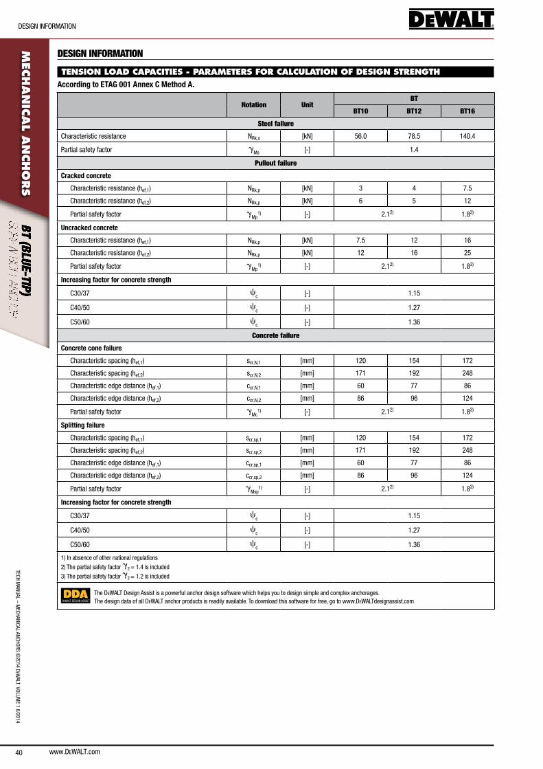
www.DEWALT.com40
DesIGn InfoRMaTIon
TecH ManUal – M
ecHanIcal ancHoRs ©2014 D
eWalT VolUM
e 1 6/2014M
ECHAN
ICAL A
NCHO
RS
DESIGN INFORMATION
TENSION LOAD CAPACITIES - PARAMETERS FOR CALCULATION OF DESIGN STRENGTHAccording to ETAG 001 Annex C Method A.
Notation UnitBT
BT10 BT12 BT16
Steel failure
characteristic resistance nRk,s [kn] 56.0 78.5 140.4
Partial safety factor gMs [-] 1.4
Pullout failure
Cracked concrete
characteristic resistance (hef,1) nRk,p [kn] 3 4 7.5
characteristic resistance (hef,2) nRk,p [kn] 6 5 12
Partial safety factor gMp
1) [-] 2.12) 1.83)
Uncracked concrete
characteristic resistance (hef,1) nRk,p [kn] 7.5 12 16
characteristic resistance (hef,2) nRk,p [kn] 12 16 25
Partial safety factor gMp
1) [-] 2.12) 1.83)
Increasing factor for concrete strength
c30/37 cc [-] 1.15
c40/50 cc [-] 1.27
c50/60 cc [-] 1.36
Concrete failure
Concrete cone failure
characteristic spacing (hef,1) scr,n,1 [mm] 120 154 172
characteristic spacing (hef,2) scr,n,2 [mm] 171 192 248
characteristic edge distance (hef,1) ccr,n,1 [mm] 60 77 86
characteristic edge distance (hef,2) ccr,n,2 [mm] 86 96 124
Partial safety factor gMc
1) [-] 2.12) 1.83)
Splitting failure
characteristic spacing (hef,1) scr,sp,1 [mm] 120 154 172
characteristic spacing (hef,2) scr,sp,2 [mm] 171 192 248
characteristic edge distance (hef,1) ccr,sp,1 [mm] 60 77 86
characteristic edge distance (hef,2) ccr,sp,2 [mm] 86 96 124
Partial safety factor gMsp
1) [-] 2.12) 1.83)
Increasing factor for concrete strength
c30/37 cc [-] 1.15
c40/50 cc [-] 1.27
c50/60 cc [-] 1.36
1) In absence of other national regulations
2) The partial safety factor g2 = 1.4 is included
3) The partial safety factor g2 = 1.2 is included
DEWALT DESIGN ASSIST
The DeWalT Design assist is a powerful anchor design software which helps you to design simple and complex anchorages.The design data of all DeWalT anchor products is readily available. To download this software for free, go to www.DeWalTdesignassist.com
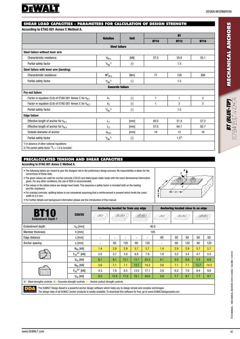
www.DEWALT.com 41
DesIGn InfoRMaTIon
TecH
Man
Ual
– M
ecHa
nIca
l an
cHoR
s ©
2014
DeW
alT
Vol
UMe
1 6/
2014
MEC
HAN
ICAL
AN
CHO
RSSHEAR LOAD CAPACITIES - PARAMETERS FOR CALCULATION OF DESIGN STRENGTH
According to ETAG 001 Annex C Method A.
Notation UnitBT
BT10 BT12 BT16
Steel failure
Steel failure without lever arm
characteristic resistance VRk,s [kn] 27.0 35.8 55.1
Partial safety factor gMs
1) [-] 1.5
Steel failure with lever arm (bending)
characteristic resistance M0Rk,s [nm] 77 128 306
Partial safety factor gMs
1) [-] 1.5
Concrete failure
Pry-out failure
factor in equation (5.6) of eTaG 001 annex c for hef,1 k1 [-] 1 1 2
factor in equation (5.6) of eTaG 001 annex c for hef,2 k2 [-] 1 2 2
Partial safety factor gMc
1) [-] 1.5
Edge failure
effective length of anchor for hef,1 lf,1 [mm] 40.0 51.4 57.2
effective length of anchor for hef,2 lf,2 [mm] 57.0 64.1 82.7
outside diameter of anchor dnom [mm] 10 12 16
Partial safety factor gMc
1) [-] 1.52)
1) In absence of other national regulations
2) The partial safety factor g2 = 1.0 is included
PRECALCULATED TENSION AND SHEAR CAPACITIES According to ETAG 001 Annex C Method A.
• The following tables are meant to give the designer aid in the preliminary design process. no responsibility is taken for the correctness of these data.
• The given values are valid for normal concrete c20/25 and static/quasi-static loads with the exact dimensional information given. for any other conditions, the use of DDa is recommended.
• The values in the tables below are design level loads. This assumes a safety factor is included both on the loading and the resistance.
• for cracked concrete, splitting failure is not considered assuming that a reinforcement is present which limits the crack width to 0.3 mm.
• for further details and background information please see the introduction of this manual.
N
V
F
sh
c
BT10Embedment Depth 1
C20/25
Anchoring located far from any edge Anchoring located close to an edge
embedment depth hef [mm] 40.0
Member thickness h [mm] 105
edge distance c [mm] - - - - - 60 60 60 60 60
anchor spacing s [mm] - 60 120 60 120 - 60 120 60 120
nRd [kn] 1.4 2.9 2.9 5.7 5.7 1.4 2.9 2.9 5.7 5.7
fRd45° [kn] 2.0 3.7 3.9 6.8 7.9 1.8 3.2 3.4 4.7 5.3
VRd [kn] 6.1 9.1 12.1 13.7 24.3 4.1 5.5 6.9 5.5 6.9
nRd [kn] 3.6 7.1 7.1 13.7 14.3 3.6 7.1 7.1 13.7 14.3
fRd45° [kn] 4.3 7.8 8.5 13.5 17.1 3.8 6.3 7.0 8.4 9.8
VRd [kn] 8.5 12.8 17.0 19.1 34.0 5.8 7.7 9.7 7.7 9.7
n - steel strengths controls n - concrete strength controls n - anchor pullout strength controls
DEWALT DESIGN ASSIST
The DeWalT Design assist is a powerful anchor design software which helps you to design simple and complex anchorages.The design data of all DeWalT anchor products is readily available. To download this software for free, go to www.DeWalTdesignassist.com
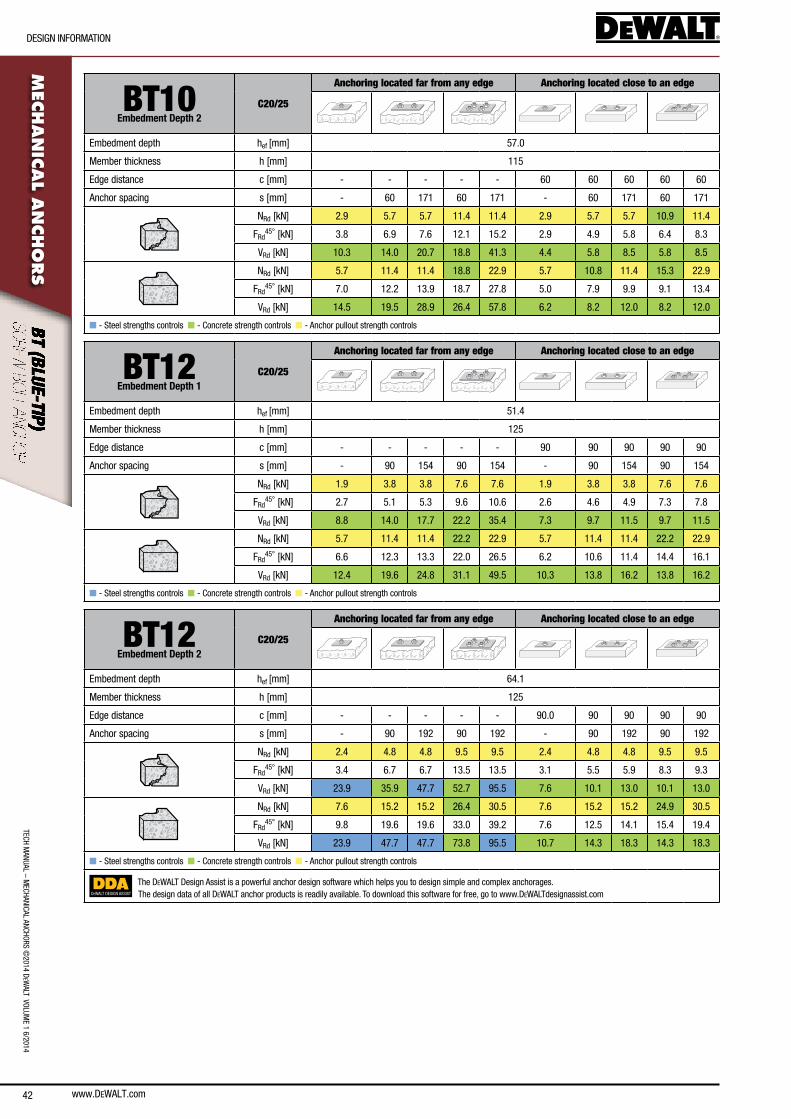
42
TecH ManUal – M
ecHanIcal ancHoRs ©2014 D
eWalT VolUM
e 1 6/2014
DesIGn InfoRMaTIon
www.DEWALT.com
MEC
HAN
ICAL A
NCHO
RS
BT10Embedment Depth 2
C20/25
Anchoring located far from any edge Anchoring located close to an edge
embedment depth hef [mm] 57.0
Member thickness h [mm] 115
edge distance c [mm] - - - - - 60 60 60 60 60
anchor spacing s [mm] - 60 171 60 171 - 60 171 60 171
nRd [kn] 2.9 5.7 5.7 11.4 11.4 2.9 5.7 5.7 10.9 11.4
fRd45° [kn] 3.8 6.9 7.6 12.1 15.2 2.9 4.9 5.8 6.4 8.3
VRd [kn] 10.3 14.0 20.7 18.8 41.3 4.4 5.8 8.5 5.8 8.5
nRd [kn] 5.7 11.4 11.4 18.8 22.9 5.7 10.8 11.4 15.3 22.9
fRd45° [kn] 7.0 12.2 13.9 18.7 27.8 5.0 7.9 9.9 9.1 13.4
VRd [kn] 14.5 19.5 28.9 26.4 57.8 6.2 8.2 12.0 8.2 12.0
n - steel strengths controls n - concrete strength controls n - anchor pullout strength controls
BT12Embedment Depth 1
C20/25
Anchoring located far from any edge Anchoring located close to an edge
embedment depth hef [mm] 51.4
Member thickness h [mm] 125
edge distance c [mm] - - - - - 90 90 90 90 90
anchor spacing s [mm] - 90 154 90 154 - 90 154 90 154
nRd [kn] 1.9 3.8 3.8 7.6 7.6 1.9 3.8 3.8 7.6 7.6
fRd45° [kn] 2.7 5.1 5.3 9.6 10.6 2.6 4.6 4.9 7.3 7.8
VRd [kn] 8.8 14.0 17.7 22.2 35.4 7.3 9.7 11.5 9.7 11.5
nRd [kn] 5.7 11.4 11.4 22.2 22.9 5.7 11.4 11.4 22.2 22.9
fRd45° [kn] 6.6 12.3 13.3 22.0 26.5 6.2 10.6 11.4 14.4 16.1
VRd [kn] 12.4 19.6 24.8 31.1 49.5 10.3 13.8 16.2 13.8 16.2
n - steel strengths controls n - concrete strength controls n - anchor pullout strength controls
BT12Embedment Depth 2
C20/25
Anchoring located far from any edge Anchoring located close to an edge
embedment depth hef [mm] 64.1
Member thickness h [mm] 125
edge distance c [mm] - - - - - 90.0 90 90 90 90
anchor spacing s [mm] - 90 192 90 192 - 90 192 90 192
nRd [kn] 2.4 4.8 4.8 9.5 9.5 2.4 4.8 4.8 9.5 9.5
fRd45° [kn] 3.4 6.7 6.7 13.5 13.5 3.1 5.5 5.9 8.3 9.3
VRd [kn] 23.9 35.9 47.7 52.7 95.5 7.6 10.1 13.0 10.1 13.0
nRd [kn] 7.6 15.2 15.2 26.4 30.5 7.6 15.2 15.2 24.9 30.5
fRd45° [kn] 9.8 19.6 19.6 33.0 39.2 7.6 12.5 14.1 15.4 19.4
VRd [kn] 23.9 47.7 47.7 73.8 95.5 10.7 14.3 18.3 14.3 18.3
n - steel strengths controls n - concrete strength controls n - anchor pullout strength controls
DEWALT DESIGN ASSIST
The DeWalT Design assist is a powerful anchor design software which helps you to design simple and complex anchorages.The design data of all DeWalT anchor products is readily available. To download this software for free, go to www.DeWalTdesignassist.com
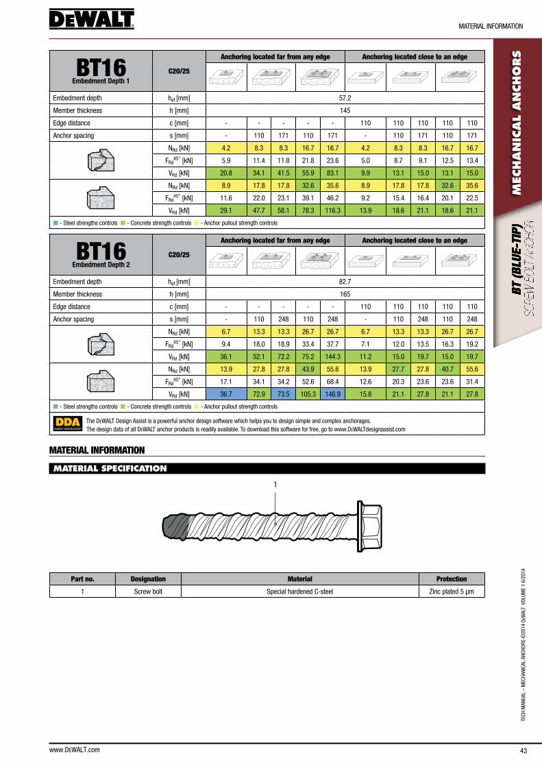
www.DEWALT.com 43
TecH
Man
Ual
– M
ecHa
nIca
l an
cHoR
s ©
2014
DeW
alT
Vol
UMe
1 6/
2014
MaTeRIal InfoRMaTIon
MEC
HAN
ICAL
AN
CHO
RS
BT16Embedment Depth 1
C20/25
Anchoring located far from any edge Anchoring located close to an edge
embedment depth hef [mm] 57.2
Member thickness h [mm] 145
edge distance c [mm] - - - - - 110 110 110 110 110
anchor spacing s [mm] - 110 171 110 171 - 110 171 110 171
nRd [kn] 4.2 8.3 8.3 16.7 16.7 4.2 8.3 8.3 16.7 16.7
fRd45° [kn] 5.9 11.4 11.8 21.8 23.6 5.0 8.7 9.1 12.5 13.4
VRd [kn] 20.8 34.1 41.5 55.9 83.1 9.9 13.1 15.0 13.1 15.0
nRd [kn] 8.9 17.8 17.8 32.6 35.6 8.9 17.8 17.8 32.6 35.6
fRd45° [kn] 11.6 22.0 23.1 39.1 46.2 9.2 15.4 16.4 20.1 22.5
VRd [kn] 29.1 47.7 58.1 78.3 116.3 13.9 18.6 21.1 18.6 21.1
n - steel strengths controls n - concrete strength controls n - anchor pullout strength controls
BT16Embedment Depth 2
C20/25
Anchoring located far from any edge Anchoring located close to an edge
embedment depth hef [mm] 82.7
Member thickness h [mm] 165
edge distance c [mm] - - - - - 110 110 110 110 110
anchor spacing s [mm] - 110 248 110 248 - 110 248 110 248
nRd [kn] 6.7 13.3 13.3 26.7 26.7 6.7 13.3 13.3 26.7 26.7
fRd45° [kn] 9.4 18.0 18.9 33.4 37.7 7.1 12.0 13.5 16.3 19.2
VRd [kn] 36.1 52.1 72.2 75.2 144.3 11.2 15.0 19.7 15.0 19.7
nRd [kn] 13.9 27.8 27.8 43.9 55.6 13.9 27.7 27.8 40.7 55.6
fRd45° [kn] 17.1 34.1 34.2 52.6 68.4 12.6 20.3 23.6 23.6 31.4
VRd [kn] 36.7 72.9 73.5 105.3 146.9 15.8 21.1 27.8 21.1 27.8
n - steel strengths controls n - concrete strength controls n - anchor pullout strength controls
DEWALT DESIGN ASSIST
The DeWalT Design assist is a powerful anchor design software which helps you to design simple and complex anchorages.The design data of all DeWalT anchor products is readily available. To download this software for free, go to www.DeWalTdesignassist.com
MATERIAL INFORMATION
MATERIAL SPECIFICATION
1
Part no. Designation Material Protection
1 screw bolt special hardened c-steel Zinc plated 5 µm
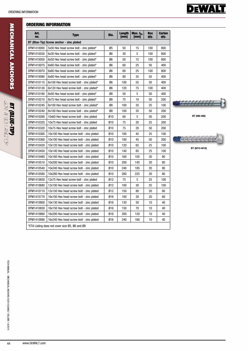
44
TecH ManUal – M
ecHanIcal ancHoRs ©2014 D
eWalT VolUM
e 1 6/2014
oRDeRInG InfoRMaTIon
www.DEWALT.com
MEC
HAN
ICAL A
NCHO
RS
ORDERING INFORMATION
Art. no. Type Dia. Length
[mm]Max. tfix
[mm]Box qty.
Carton qty.
BT (M6-M8)
BT (M10-M16)
BT (Blue-Tip) Screw anchor - zinc plated
DfM1410000 5x50 Hex head screw bolt - zinc plated* Ø5 50 15 100 800
DfM1410030 6x30 Hex head screw bolt - zinc plated* Ø6 30 5 100 800
DfM1410050 6x50 Hex head screw bolt - zinc plated* Ø6 50 15 100 800
DfM141007s 6x60 Hex head screw bolt - zinc plated* Ø6 60 25 50 400
DfM1410070 6x60 Hex head screw bolt - zinc plated* Ø6 60 25 100 800
DfM1410090 6x80 Hex head screw bolt - zinc plated* Ø6 80 35 50 400
DfM141011s 6x100 Hex head screw bolt - zinc plated* Ø6 100 55 50 400
DfM1410130 6x120 Hex head screw bolt - zinc plated* Ø6 120 75 100 400
DfM1410180 8x50 Hex head screw bolt - zinc plated* Ø8 50 5 50 400
DfM1410210 8x75 Hex head screw bolt - zinc plated* Ø8 75 10 50 200
DfM141024s 8x100 Hex head screw bolt - zinc plated* Ø8 100 35 25 100
DfM1410240 8x100 Hex head screw bolt - zinc plated* Ø8 100 35 50 200
DfM1410280 10x60 Hex head screw bolt - zinc plated Ø10 60 5 50 200
DfM141032s 10x75 Hex head screw bolt - zinc plated Ø10 75 20 25 200
DfM1410320 10x75 Hex head screw bolt - zinc plated Ø10 75 20 50 200
DfM141036s 10x100 Hex head screw bolt - zinc plated Ø10 100 45 25 100
DfM1410360 10x100 Hex head screw bolt - zinc plated Ø10 100 45 50 200
DfM1410430 10x120 Hex head screw bolt - zinc plated Ø10 120 65 25 100
DfM1410450 10x140 Hex head screw bolt - zinc plated Ø10 140 85 25 100
DfM1410480 10x160 Hex head screw bolt - zinc plated Ø10 160 105 20 80
DfM1410510 10x200 Hex head screw bolt - zinc plated Ø10 200 145 20 80
DfM1410540 10x240 Hex head screw bolt - zinc plated Ø10 240 185 20 80
DfM1410580 10x280 Hex head screw bolt - zinc plated Ø10 280 225 20 80
DfM1410650 12x75 Hex head screw bolt - zinc plated Ø12 75 5 25 100
DfM1410680 12x100 Hex head screw bolt - zinc plated Ø12 100 30 25 100
DfM1410710 12x150 Hex head screw bolt - zinc plated Ø12 150 80 20 80
DfM1410770 16x100 Hex head screw bolt - zinc plated Ø16 100 20 20 80
DfM1410800 16x130 Hex head screw bolt - zinc plated Ø16 130 50 10 40
DfM1410830 16x150 Hex head screw bolt - zinc plated Ø16 150 70 10 40
DfM1410860 16x200 Hex head screw bolt - zinc plated Ø16 200 120 10 40
DfM1410890 16x240 Hex head screw bolt - zinc plated Ø16 240 160 10 40
*eTa listing does not cover size Ø5, Ø6 and Ø8
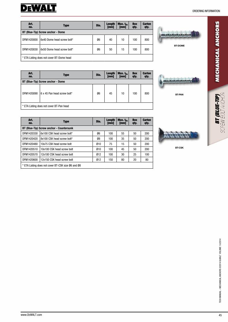
www.DEWALT.com 45
TECH
MAN
UAL
– M
ECHA
NiCA
L AN
CHor
s ©
2014
DeW
ALT
VoL
UME
1 6/
2014
orDEriNg iNforMATioN
Mec
han
ical
an
cho
rsArt.
no. Type Dia. Length [mm]
Max. tfix[mm]
Box qty.
Carton qty.
BT-DOME
BT (Blue-Tip) Screw anchor - Dome
DfM1420000 6x40 Dome head screw bolt* Ø6 40 10 100 800
DfM1420030 6x50 Dome head screw bolt* Ø6 50 15 100 800
* ETA Listing does not cover BT-Dome head
Art. no. Type Dia. Length
[mm]Max. tfix
[mm]Box qty.
Carton qty.
BT-PAN
BT (Blue-Tip) Screw anchor - Dome
DfM1420090 6 x 45 Pan head screw bolt* Ø6 45 10 100 800
* ETA Listing does not cover BT-Pan head
Art. no. Type Dia. Length
[mm]Max. tfix
[mm]Box qty.
Carton qty.
BT-CSK
BT (Blue-Tip) Screw anchor - Countersunk
DfM1420330 6x100 CsK head screw bolt* Ø6 100 55 50 200
DfM1420420 8x100 CsK head screw bolt* Ø8 100 35 50 200
DfM1420480 10x75 CsK head screw bolt Ø10 75 15 50 200
DfM1420510 10x100 CsK head screw bolt Ø10 100 45 50 200
DfM1420570 12x100 CsK head screw bolt Ø12 100 30 25 100
DfM1420600 12x150 CsK head screw bolt Ø12 150 80 20 80
* ETA Listing does not cover BT-CsK size Ø6 and Ø8
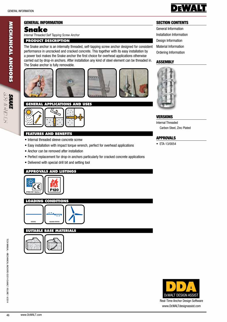
www.DEWALT.com46
GeneRal InfoRMaTIon
TecH ManUal – M
ecHanIcal ancHoRs ©2014 D
eWalT VolUM
e 1 6/2014M
ECHAN
ICAL A
NCHO
RS
SECTION CONTENTSGeneral Information
Installation Information
Design Information
Material Information
ordering Information
ASSEMBLY
VERSIONSInternal Threaded
carbon steel, Zinc Plated
APPROVALS• eTa-13/0054
GENERAL INFORMATION
SnakeInternal Threaded Self Tapping Screw Anchor
PRODUCT DESCRIPTION
The snake anchor is an internally threaded, self-tapping screw anchor designed for consistent performance in uncracked and cracked concrete. This together with its easy installation by a power tool makes the snake anchor the first choice for overhead applications otherwise carried out by drop-in anchors. after installation any kind of steel element can be threaded in. The snake anchor is fully removable.
GENERAL APPLICATIONS AND USES
FEATURES AND BENEFITS
• Internal threaded sleeve concrete screw
• easy installation with impact torque wrench, perfect for overhead applications
• anchor can be removed after installation
• Perfect replacement for drop-in anchors particularly for cracked concrete applications
• Delivered with special drill bit and setting tool
APPROVALS AND LISTINGS
ETAG 001 Option 1 F120
LOADING CONDITIONS
STATIC QUASI-STATIC
SUITABLE BASE MATERIALS
DEWALT DESIGN ASSISTReal-Time anchor Design software
www.DeWalTdesignassist.com

www.DEWALT.com 47
InsTallaTIon InfoRMaTIon
TecH
Man
Ual
– M
ecHa
nIca
l an
cHoR
s ©
2014
DeW
alT
Vol
UMe
1 6/
2014
MEC
HAN
ICAL
AN
CHO
RSINSTALLATION INFORMATION
INSTALLATION DATA
Notation UnitSnake
M8 M10
anchor diameter d [mm] 12.7 12.7
nominal drill bit diameter d0 [mm] 12.7 (1/2”) 12.7 (1/2”)
Diameter of hole clearance in fixture df [mm] 9 12
nominal embedment depth hnom [mm] 41 41
effective embedment depth hef [mm] 28 28
Drill hole depth h1 [mm] 50 50
Minimum member thickness hmin [mm] 100 100
Minimum spacing smin [mm] 80 80
Minimum edge distance cmin [mm] 80 80
Maximum torque threaded rod Tmax,tr [nm] 10 10
Maximum torque impact wrench Tmax,iw [nm] 185 468
h1
Tmax, tr
df
d0
hmin
hnom
INSTALLATION INSTRUCTIONS
1.) Using the proper drill bit size, drill a hole into the base material to the required depth.
2.) Remove dust and debris from the hole using a hand pump or compressed air.
3.) Attach the Snake setting tool to an impact wrench, mount the anchor onto the setting tool.
4.) Drive the anchor until the tool comes into contact with the surface of the base material.
5.) Insert threaded rod or bolt.
for complete installation instructions, see technical approval.
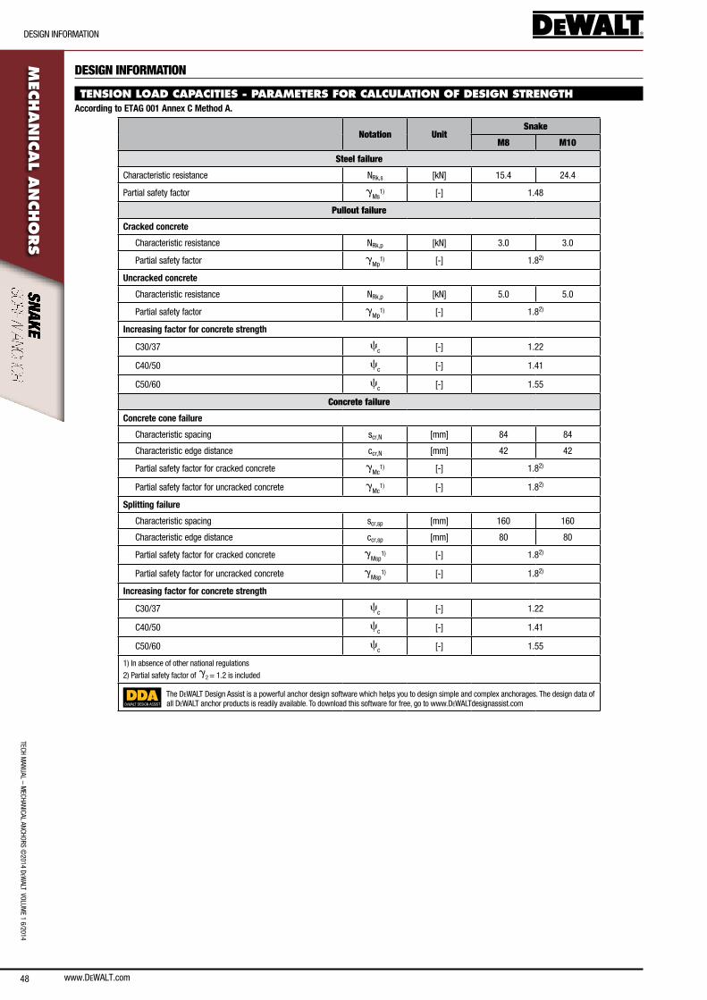
www.DEWALT.com48
DesIGn InfoRMaTIon
TecH ManUal – M
ecHanIcal ancHoRs ©2014 D
eWalT VolUM
e 1 6/2014M
ECHAN
ICAL A
NCHO
RS
DESIGN INFORMATION
TENSION LOAD CAPACITIES - PARAMETERS FOR CALCULATION OF DESIGN STRENGTHAccording to ETAG 001 Annex C Method A.
Notation UnitSnake
M8 M10
Steel failure
characteristic resistance nRk,s [kn] 15.4 24.4
Partial safety factor gMs
1) [-] 1.48
Pullout failure
Cracked concrete
characteristic resistance nRk,p [kn] 3.0 3.0
Partial safety factor gMp
1) [-] 1.82)
Uncracked concrete
characteristic resistance nRk,p [kn] 5.0 5.0
Partial safety factor gMp
1) [-] 1.82)
Increasing factor for concrete strength
c30/37 cc [-] 1.22
c40/50 cc [-] 1.41
c50/60 cc [-] 1.55
Concrete failure
Concrete cone failure
characteristic spacing scr,n [mm] 84 84
characteristic edge distance ccr,n [mm] 42 42
Partial safety factor for cracked concrete gMc
1) [-] 1.82)
Partial safety factor for uncracked concrete gMc
1) [-] 1.82)
Splitting failure
characteristic spacing scr,sp [mm] 160 160
characteristic edge distance ccr,sp [mm] 80 80
Partial safety factor for cracked concrete gMsp
1) [-] 1.82)
Partial safety factor for uncracked concrete gMsp
1) [-] 1.82)
Increasing factor for concrete strength
c30/37 cc [-] 1.22
c40/50 cc [-] 1.41
c50/60 cc [-] 1.55
1) In absence of other national regulations
2) Partial safety factor of g2 = 1.2 is included
DEWALT DESIGN ASSIST
The DeWalT Design assist is a powerful anchor design software which helps you to design simple and complex anchorages. The design data of all DeWalT anchor products is readily available. To download this software for free, go to www.DeWalTdesignassist.com
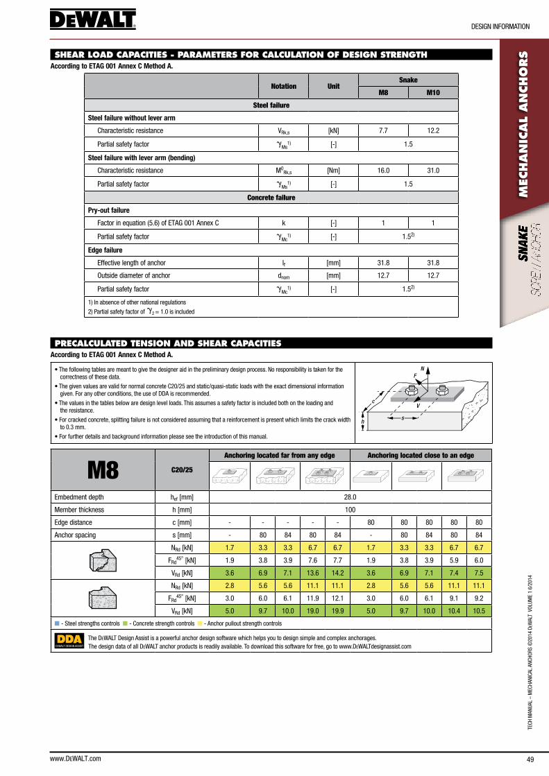
www.DEWALT.com 49
TecH
Man
Ual
– M
ecHa
nIca
l an
cHoR
s ©
2014
DeW
alT
Vol
UMe
1 6/
2014
DesIGn InfoRMaTIon
MEC
HAN
ICAL
AN
CHO
RSSHEAR LOAD CAPACITIES - PARAMETERS FOR CALCULATION OF DESIGN STRENGTH
According to ETAG 001 Annex C Method A.
Notation UnitSnake
M8 M10
Steel failure
Steel failure without lever arm
characteristic resistance VRk,s [kn] 7.7 12.2
Partial safety factor gMs
1) [-] 1.5
Steel failure with lever arm (bending)
characteristic resistance M0Rk,s [nm] 16.0 31.0
Partial safety factor gMs
1) [-] 1.5
Concrete failure
Pry-out failure
factor in equation (5.6) of eTaG 001 annex c k [-] 1 1
Partial safety factor gMc
1) [-] 1.52)
Edge failure
effective length of anchor lf [mm] 31.8 31.8
outside diameter of anchor dnom [mm] 12.7 12.7
Partial safety factor gMc
1) [-] 1.52)
1) In absence of other national regulations
2) Partial safety factor of g2 = 1.0 is included
PRECALCULATED TENSION AND SHEAR CAPACITIES According to ETAG 001 Annex C Method A.
• The following tables are meant to give the designer aid in the preliminary design process. no responsibility is taken for the correctness of these data.
• The given values are valid for normal concrete c20/25 and static/quasi-static loads with the exact dimensional information given. for any other conditions, the use of DDa is recommended.
• The values in the tables below are design level loads. This assumes a safety factor is included both on the loading and the resistance.
• for cracked concrete, splitting failure is not considered assuming that a reinforcement is present which limits the crack width to 0.3 mm.
• for further details and background information please see the introduction of this manual.
N
V
F
sh
c
M8 C20/25
Anchoring located far from any edge Anchoring located close to an edge
embedment depth hef [mm] 28.0
Member thickness h [mm] 100
edge distance c [mm] - - - - - 80 80 80 80 80
anchor spacing s [mm] - 80 84 80 84 - 80 84 80 84
nRd [kn] 1.7 3.3 3.3 6.7 6.7 1.7 3.3 3.3 6.7 6.7
fRd45° [kn] 1.9 3.8 3.9 7.6 7.7 1.9 3.8 3.9 5.9 6.0
VRd [kn] 3.6 6.9 7.1 13.6 14.2 3.6 6.9 7.1 7.4 7.5
nRd [kn] 2.8 5.6 5.6 11.1 11.1 2.8 5.6 5.6 11.1 11.1
fRd45° [kn] 3.0 6.0 6.1 11.9 12.1 3.0 6.0 6.1 9.1 9.2
VRd [kn] 5.0 9.7 10.0 19.0 19.9 5.0 9.7 10.0 10.4 10.5
n - steel strengths controls n - concrete strength controls n - anchor pullout strength controls
DEWALT DESIGN ASSIST
The DeWalT Design assist is a powerful anchor design software which helps you to design simple and complex anchorages.The design data of all DeWalT anchor products is readily available. To download this software for free, go to www.DeWalTdesignassist.com
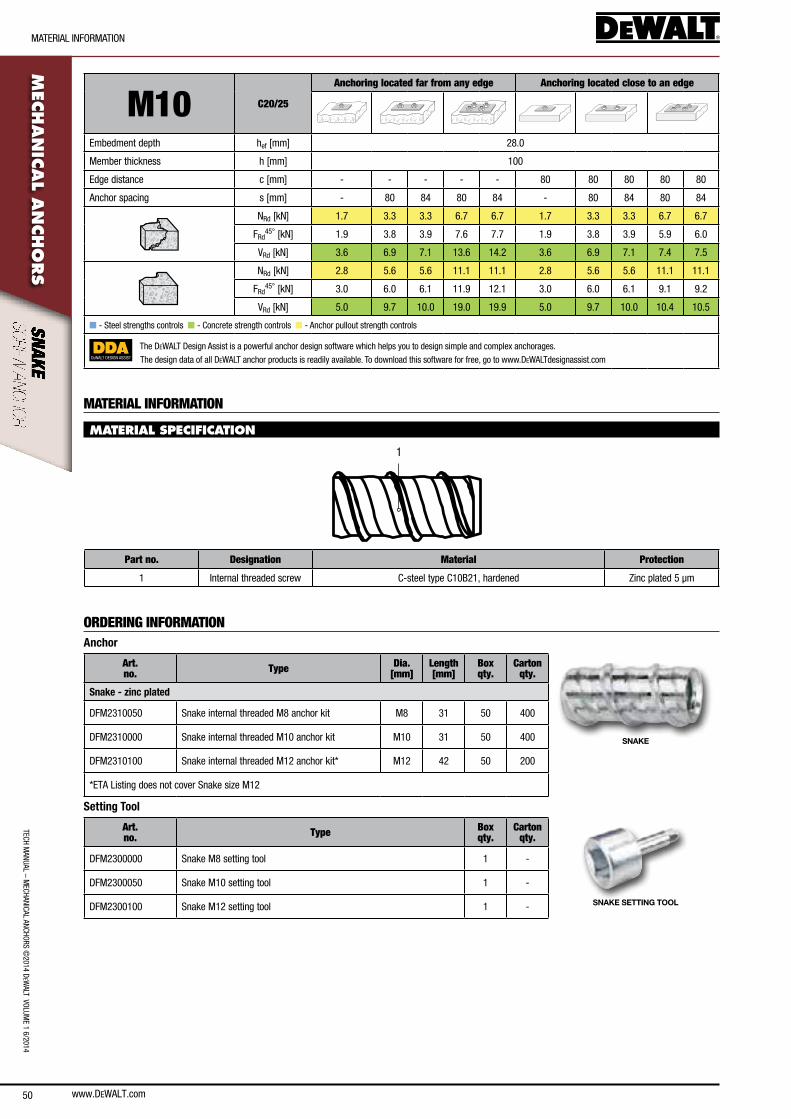
50
TecH ManUal – M
ecHanIcal ancHoRs ©2014 D
eWalT VolUM
e 1 6/2014
MaTeRIal InfoRMaTIon
www.DEWALT.com
MEC
HAN
ICAL A
NCHO
RS
M10 C20/25
Anchoring located far from any edge Anchoring located close to an edge
embedment depth hef [mm] 28.0
Member thickness h [mm] 100
edge distance c [mm] - - - - - 80 80 80 80 80
anchor spacing s [mm] - 80 84 80 84 - 80 84 80 84
nRd [kn] 1.7 3.3 3.3 6.7 6.7 1.7 3.3 3.3 6.7 6.7
fRd45° [kn] 1.9 3.8 3.9 7.6 7.7 1.9 3.8 3.9 5.9 6.0
VRd [kn] 3.6 6.9 7.1 13.6 14.2 3.6 6.9 7.1 7.4 7.5
nRd [kn] 2.8 5.6 5.6 11.1 11.1 2.8 5.6 5.6 11.1 11.1
fRd45° [kn] 3.0 6.0 6.1 11.9 12.1 3.0 6.0 6.1 9.1 9.2
VRd [kn] 5.0 9.7 10.0 19.0 19.9 5.0 9.7 10.0 10.4 10.5
n - steel strengths controls n - concrete strength controls n - anchor pullout strength controls
DEWALT DESIGN ASSIST
The DeWalT Design assist is a powerful anchor design software which helps you to design simple and complex anchorages.
The design data of all DeWalT anchor products is readily available. To download this software for free, go to www.DeWalTdesignassist.com
MATERIAL INFORMATION
MATERIAL SPECIFICATION
1
Part no. Designation Material Protection
1 Internal threaded screw c-steel type c10b21, hardened Zinc plated 5 µm
ORDERING INFORMATIONAnchor
Art. no. Type Dia.
[mm]Length [mm]
Box qty.
Carton qty.
SNAKE
Snake - zinc plated
DfM2310050 snake internal threaded M8 anchor kit M8 31 50 400
DfM2310000 snake internal threaded M10 anchor kit M10 31 50 400
DfM2310100 snake internal threaded M12 anchor kit* M12 42 50 200
*eTa listing does not cover snake size M12
Setting Tool
Art. no. Type Box
qty. Carton
qty.
SNAKE SETTING TOOL
DfM2300000 snake M8 setting tool 1 -
DfM2300050 snake M10 setting tool 1 -
DfM2300100 snake M12 setting tool 1 -
TecH
Man
Ual
– M
ecHa
nIca
l an
cHoR
s ©
2014
DeW
alT
Vol
UMe
1 6/
2014
aDHesIVe ancHoR oVeRVIeW
www.DEWALT.com
ADHES
IVE
AN
CHO
RSSECTION CONTENT
Injection Adhesive Systems
Vinylester:
ac100-PRo
epoxy:
Pure150-PRo
Pure110-PRo
Polyester:
PV50-PRo
PV45-PRo
Capsule Systems
sc-PRo
ADHESIVE ANCHOR OVERVIEW
adhesive anchors offer many advantages for applications requiring high load capacities yet not allowing mechanical expansion forces in the base material. adhesive systems also include the ability to be used with a variety of steel element materials.
The load transfer mechanism of adhesive anchors bases on bond formed by the adhesive between the anchor and the wall of the drilled hole. The annular gap is completely filled with adhesive, sealing the anchor hole against weather. adhesive mortars consist of aggregates and binder in the form of unsaturated polyester, vinylester, vinylester with cement (hybrid systems) or epoxy. all adhesive types have different strengths and cost advantages.
adhesive systems are further classified according to their delivery method. Injection systems provide the adhesive in plastic cartridges which is mixed through a static mixer and dispensed into the drilled hole. sufficient cleaning of the drilled hole prior to installation of the anchor or reinforce-ment bar is of paramount importance. Capsule systems have the adhesive encapsulated in a glass capsule which is inserted into the drilled hole and mixed during anchor setting.
In europe and many other countries, adhesive anchors used for applications in concrete are designed according to the EOTA TR 029. adhesive anchors used for applications in masonry can be designed according to the ETAG 029 Annex C. adhesive rebar anchoring systems are designed in compliance with structural concrete design codes as the eurocode 2 en 1992-1-1.
51
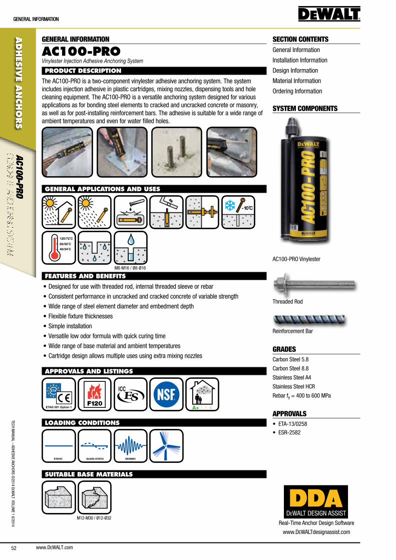
www.DEWALT.com52
ADHES
IVE A
NCHO
RS
GeneRal InfoRMaTIon
TecH ManUal – aDHesIVe ancHoRs ©
2014 DeW
alT VolUMe 1 6/2014
GeneRal InfoRMaTIon
GENERAL INFORMATION
AC100-PROVinylester Injection Adhesive Anchoring System
PRODUCT DESCRIPTION
The ac100-PRo is a two-component vinylester adhesive anchoring system. The system includes injection adhesive in plastic cartridges, mixing nozzles, dispensing tools and hole cleaning equipment. The ac100-PRo is a versatile anchoring system designed for various applications as for bonding steel elements to cracked and uncracked concrete or masonry, as well as for post-installing reinforcement bars. The adhesive is suitable for a wide range of ambient temperatures and even for water filled holes.
GENERAL APPLICATIONS AND USES
-10 C̊
40/24˚C
80/50˚C
120/72˚C
FEATURES AND BENEFITS
• Designed for use with threaded rod, internal threaded sleeve or rebar
• consistent performance in uncracked and cracked concrete of variable strength
• Wide range of steel element diameter and embedment depth
• flexible fixture thicknesses
• simple installation
• Versatile low odor formula with quick curing time
• Wide range of base material and ambient temperatures
• cartridge design allows multiple uses using extra mixing nozzles
APPROVALS AND LISTINGS
ETAG 001 Option 1 F120
A+ A B C
LOADING CONDITIONS
STATIC QUASI-STATIC SEISMIC
SUITABLE BASE MATERIALS
SECTION CONTENTSGeneral Information
Installation Information
Design Information
Material Information
ordering Information
SYSTEM COMPONENTS
ac100-PRo Vinylester
Threaded Rod
Reinforcement bar
GRADEScarbon steel 5.8
carbon steel 8.8
stainless steel a4
stainless steel HcR
Rebar fy = 400 to 600 MPa
APPROVALS• eTa-13/0258
• esR-2582
DEWALT DESIGN ASSISTReal-Time anchor Design software
www.DeWalTdesignassist.com
M8-M16 / Ø8-Ø16
M12-M30 / Ø12-Ø32
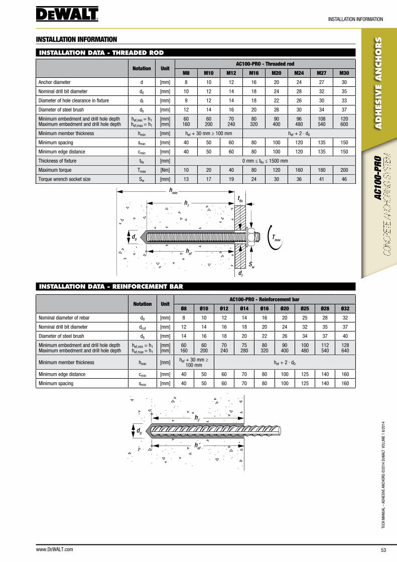
www.DEWALT.com 53
TecH
Man
Ual
– aD
HesI
Ve a
ncHo
Rs ©
2014
DeW
alT
Vol
UMe
1 6/
2014
ADHES
IVE
AN
CHO
RS
InsTallaTIon InfoRMaTIon
INSTALLATION INFORMATION
INSTALLATION DATA - THREADED ROD
Notation UnitAC100-PRO - Threaded rod
M8 M10 M12 M16 M20 M24 M27 M30
anchor diameter d [mm] 8 10 12 16 20 24 27 30
nominal drill bit diameter d0 [mm] 10 12 14 18 24 28 32 35
Diameter of hole clearance in fixture df [mm] 9 12 14 18 22 26 30 33
Diameter of steel brush db [mm] 12 14 16 20 26 30 34 37
Minimum embedment and drill hole depth Maximum embedment and drill hole depth
hef,min = h1 hef,max = h1
[mm] [mm]
60 160
60 200
70 240
80 320
90 400
96 480
108 540
120 600
Minimum member thickness hmin [mm] hef + 30 mm ≥ 100 mm hef + 2 · d0
Minimum spacing smin [mm] 40 50 60 80 100 120 135 150
Minimum edge distance cmin [mm] 40 50 60 80 100 120 135 150
Thickness of fixture tfix [mm] 0 mm ≤ tfix ≤ 1500 mm
Maximum torque Tmax [nm] 10 20 40 80 120 160 180 200
Torque wrench socket size sw [mm] 13 17 19 24 30 36 41 46
hmin
h1
hef
d0
Sw
Tmax
df
tfix
INSTALLATION DATA - REINFORCEMENT BAR
Notation UnitAC100-PRO - Reinforcement bar
Ø8 Ø10 Ø12 Ø14 Ø16 Ø20 Ø25 Ø28 Ø32
nominal diameter of rebar d0 [mm] 8 10 12 14 16 20 25 28 32
nominal drill bit diameter dcut [mm] 12 14 16 18 20 24 32 35 37
Diameter of steel brush db [mm] 14 16 18 20 22 26 34 37 40
Minimum embedment and drill hole depth Maximum embedment and drill hole depth
hef,min = h1 hef,max = h1
[mm] [mm]
60 160
60 200
70 240
75 280
80 320
90 400
100 480
112 540
128 640
Minimum member thickness hmin [mm] hef + 30 mm ≥ 100 mm hef + 2 · d0
Minimum edge distance cmin [mm] 40 50 60 70 80 100 125 140 160
Minimum spacing smin [mm] 40 50 60 70 80 100 125 140 160
hef
d0
h1

www.DEWALT.com54
TecH ManUal – aDHesIVe ancHoRs ©
2014 DeW
alT VolUMe 1 6/2014
ADHES
IVE A
NCHO
RS
InsTallaTIon InfoRMaTIon
INSTALLATION INSTRUCTIONS
4X 4X 4X
e.g.
20˚C
45 mins.
1.) Using the proper drill bit size, drill a hole into the base material to the required depth.
2.) Blow the hole clean using a hand pump or compressed air 4 times minimum.
3.) Brush the hole with the proper wire brush 4 times minimum.
4.) Blow the hole clean using a hand pump or compressed air 4 times minimum.
5.) After dispensing a minimum of 3 strokes, fill the hole up to approximately 2/3 with adhesive.
6.) Push the steel element into the hole while turning slightly.
7.) Allow the adhesive to cure for the time specified for the actual concrete temperature prior to applying any load.
for complete installation instructions, see technical approval.
Concrete temperature Working time Minimum curing time1)
≥ - 10°c 90 min 24 h
≥ - 5°c 90 min 14 h
≥ 0°c 45 min 7 h
≥ + 5°c 25 min 2 h
≥ + 10°c 15 min 80 min
≥ + 20°c 6 min 45 min
≥ + 30°c 4 min 25 min
≥ + 35°c 2 min 20 min
≥ + 40°c 1.5 min 15 min
1) Time data for dry concrete, double curing time for wet concrete
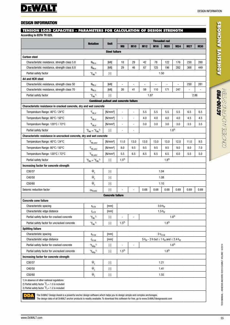
www.DEWALT.com 55
TecH
Man
Ual
– aD
HesI
Ve a
ncHo
Rs ©
2014
DeW
alT
Vol
UMe
1 6/
2014
ADHES
IVE
AN
CHO
RS
DesIGn InfoRMaTIon
DESIGN INFORMATION
TENSION LOAD CAPACITIES - PARAMETERS FOR CALCULATION OF DESIGN STRENGTHAccording to EOTA TR 029.
Notation UnitThreaded rod
M8 M10 M12 M16 M20 M24 M27 M30
Steel failure
Carbon steel
characteristic resistance, strength class 5.8 nRk,s [kn] 18 29 42 78 122 176 230 280
characteristic resistance, strength class 8.8 nRk,s [kn] 29 46 67 125 196 282 368 449
Partial safety factor gMs
1) [-] 1.50
A4 and HCR steel
characteristic resistance, strength class 50 nRk,s [kn] - - - - - - 230 281
characteristic resistance, strength class 70 nRk,s [kn] 26 41 59 110 171 247 - -
Partial safety factor gMs
1) [-] 1.87 2.86
Combined pullout and concrete failure
Characteristic resistance in cracked concrete, dry and wet concrete
Temperature Range: 40°c / 24°c tRk,cr [n/mm²] - - 5.5 5.5 5.5 5.5 6.5 6.5
Temperature Range: 80°c / 50°c tRk,cr [n/mm²] - - 4.0 4.0 4.0 4.0 4.5 4.5
Temperature Range: 120°c / 72°c tRk,cr [n/mm²] - - 3.0 3.0 3.0 3.0 3.5 3.5
Partial safety factor gMc = gMp
1) [-] - - 1.83)
Characteristic resistance in uncracked concrete, dry and wet concrete
Temperature Range: 40°c / 24°c tRk,uncr [n/mm²] 11.0 13.0 13.0 13.0 13.0 12.0 11.0 9.5
Temperature Range: 80°c / 50°c tRk,uncr [n/mm²] 8.0 9.5 9.5 9.5 9.5 9.0 8.0 7.0
Temperature Range: 120°c / 72°c tRk,uncr [n/mm²] 5.5 6.5 6.5 6.5 6.5 6.0 5.5 5.0
Partial safety factor gMc = gMp
1) [-] 1.52) 1.83)
Increasing factor for concrete strength
c30/37 cc [-] 1.04
c40/50 cc [-] 1.08
c50/60 cc [-] 1.10
seismic reduction factor an,seis [-] - - 0.68 0.68 0.68 0.69 0.69 0.69
Concrete failure
Concrete cone failure
characteristic spacing scr,n [mm] 3.0·hef
characteristic edge distance ccr,n [mm] 1.5·hef
Partial safety factor for cracked concrete gMc
1) [-] - - 1.83)
Partial safety factor for uncracked concrete gMc
1) [-] 1.52) 1.83)
Splitting failure
characteristic spacing scr,sp [mm] 2·ccr,sp
characteristic edge distance ccr,sp [mm] 5·hef - 2·h but ≥ 1·hef and ≤ 2.4·hef
Partial safety factor for cracked concrete gMsp
1) [-] - - 1.83)
Partial safety factor for uncracked concrete gMsp
1) [-] 1.52) 1.83)
Increasing factor for concrete strength
c30/37 cc [-] 1.21
c40/50 cc [-] 1.41
c50/60 cc [-] 1.55
1) In absence of other national regulations
2) Partial safety factor g2 = 1.0 is included
3) Partial safety factor g2 = 1.2 is included
DEWALT DESIGN ASSIST
The DeWalT Design assist is a powerful anchor design software which helps you to design simple and complex anchorages.The design data of all DeWalT anchor products is readily available. To download this software for free, go to www.DeWalTdesignassist.com
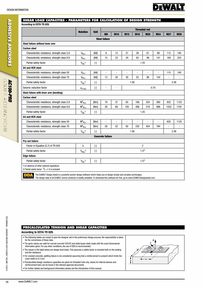
www.DEWALT.com56
TecH ManUal – aDHesIVe ancHoRs ©
2014 DeW
alT VolUMe 1 6/2014
ADHES
IVE A
NCHO
RS
DesIGn InfoRMaTIon
SHEAR LOAD CAPACITIES - PARAMETERS FOR CALCULATION OF DESIGN STRENGTHAccording to EOTA TR 029.
Notation UnitThreaded rod
M8 M10 M12 M16 M20 M24 M27 M30
Steel failure
Steel failure without lever arm
Carbon steel
characteristic resistance, strength class 5.8 VRk,s [kn] 9 15 21 39 61 88 115 140
characteristic resistance, strength class 8.8 VRk,s [kn] 15 23 34 63 98 141 184 224
Partial safety factor gMs
1) [-] 1.25
A4 and HCR steel
characteristic resistance, strength class 50 VRk,s [kn] - - - - - - 115 140
characteristic resistance, strength class 70 VRk,s [kn] 13 20 30 55 86 124 - -
Partial safety factor gMs
1) [-] 1.56 2.38
seismic reduction factor aV,seis [-] - - 0.70
Steel failure with lever arm (bending)
Carbon steel
characteristic resistance, strength class 5.8 M0Rk,s [nm] 19 37 65 166 324 560 833 1123
characteristic resistance, strength class 8.8 M0Rk,s [nm] 30 60 105 266 519 896 1333 1797
Partial safety factor gMs
1) [-] 1.25
A4 and HCR steel
characteristic resistance, strength class 50 M0Rk,s [nm] - - - - - - 832 1125
characteristic resistance, strength class 70 M0Rk,s [nm] 26 52 92 232 454 784 - -
Partial safety factor gMs
1) [-] 1.56 2.38
Concrete failure
Pry-out failure
factor in equation (5.7) of TR 029 k [-] 2
Partial safety factor gMcp
1) [-] 1.52)
Edge failure
Partial safety factor gMc
1) [-] 1.52)
1) In absence of other national regulations
2) Partial safety factor g2 =1.0 is included
DEWALT DESIGN ASSIST
The DeWalT Design assist is a powerful anchor design software which helps you to design simple and complex anchorages.The design data of all DeWalT anchor products is readily available. To download this software for free, go to www.DeWalTdesignassist.com
PRECALCULATED TENSION AND SHEAR CAPACITIES According to EOTA TR 029.
• The following tables are meant to give the designer aid in the preliminary design process. no responsibility is taken for the correctness of these data.
• The given values are valid for normal concrete c20/25 and static/quasi-static loads with the exact dimensional information given. for any other conditions, the use of DDa is recommended.
• The values in the table below are design level loads. This assumes a safety factor is included both on the loading and the resistance.
• for cracked concrete, splitting failure is not considered assuming that a reinforcement is present which limits the crack width to 0.3 mm.
• Precalculated design resistance capacities are given for threaded rods only, values for internal sleeves and reinforcement bars can be found in the relevant approval documents.
• for further details and background information please see the introduction of this manual.
N
V
F
sh
c
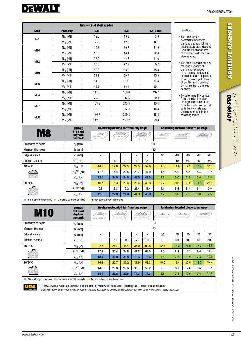
www.DEWALT.com 57
TecH
Man
Ual
– aD
HesI
Ve a
ncHo
Rs ©
2014
DeW
alT
Vol
UMe
1 6/
2014
ADHES
IVE
AN
CHO
RS
DesIGn InfoRMaTIon
Influence of steel grades
Instructions:
• The steel grade potentially influences the load capacity of the anchor. left table depicts ultimate steel strengths of threaded rods for given steel grades.
• The steel strength equals the load capacity of the anchor provided other failure modes, i.e. concrete failure or pullout failure, do not yield lower strengths and therefore do not control the anchor capacity.
• To determine the critical failure mode, the steel strength identified in left table has to be compared with the concrete and pullout strengths in the following tables.
Size Property 5.8 8.8 A4 / HCR
M8nRd [kn] 12.0 19.3 13.9
VRd [kn] 7.2 12.0 8.3
M10nRd [kn] 19.3 30.7 21.9
VRd [kn] 12.0 18.4 12.8
M12nRd [kn] 28.0 44.7 31.6
VRd [kn] 16.8 27.2 19.2
M16nRd [kn] 52.0 83.3 58.8
VRd [kn] 31.2 50.4 35.3
M20nRd [kn] 81.3 130.7 91.4
VRd [kn] 48.8 78.4 55.1
M24nRd [kn] 117.3 188.0 132.1
VRd [kn] 70.4 112.8 79.5
M27nRd [kn] 153.3 245.3 80.4
VRd [kn] 92.0 147.2 48.3
M30nRd [kn] 186.7 299.3 98.3
VRd [kn] 112.0 179.2 58.8
M8C20/25
8.8 steel dry/wetconcrete
Anchoring located far from any edge Anchoring located close to an edge
embedment depth hef [mm] 80
Member thickness h [mm] 110
edge distance c [mm] - - - - - 40 40 40 40 40
anchor spacing s [mm] 0 40 240 40 240 0 40 240 40 240
40/24˚c nRd [kn] 14.7 19.9 29.5 27.5 59.0 8.6 11.6 17.2 14.8 34.3
fRd45° [kn] 11.2 18.4 22.5 29.7 44.9 4.4 5.9 8.8 6.3 10.4
VRd [kn] 12.0 24.0 24.0 48.0 48.0 3.7 5.0 7.5 5.0 7.5
80/50˚c nRd [kn] 10.7 15.3 21.4 22.4 42.9 6.7 9.6 13.5 14.8 26.9
fRd45° [kn] 9.6 15.8 19.2 25.4 38.4 4.1 5.6 8.1 6.3 9.9
VRd [kn] 12.0 24.0 24.0 44.9 48.0 3.7 5.0 7.5 5.0 7.5
n - steel strengths controls n - concrete strength controls n - anchor pullout strength controls
M10C20/25
8.8 steel dry/wetconcrete
Anchoring located far from any edge Anchoring located close to an edge
embedment depth hef [mm] 100
Member thickness h [mm] 130
edge distance c [mm] - - - - - 50 50 50 50 50
anchor spacing s [mm] 0 50 300 50 300 0 50 300 50 300
40/24˚c nRd [kn] 22.7 28.7 45.4 37.0 90.8 12.7 14.3 21.0 16.7 42.7
fRd45° [kn] 17.2 27.4 34.5 41.8 69.0 6.5 8.2 12.2 8.6 14.8
VRd [kn] 18.4 36.8 36.8 73.6 73.6 5.5 7.3 10.9 7.3 10.9
80/50˚c nRd [kn] 16.6 22.7 33.2 31.9 66.3 10.0 13.6 20.0 16.7 39.9
fRd45° [kn] 14.8 23.8 29.6 37.7 59.2 6.0 8.1 12.0 8.6 14.6
VRd [kn] 18.4 36.8 36.8 73.6 73.6 5.5 7.3 10.9 7.3 10.9
n - steel strengths controls n - concrete strength controls n - anchor pullout strength controls
DEWALT DESIGN ASSIST
The DeWalT Design assist is a powerful anchor design software which helps you to design simple and complex anchorages.The design data of all DeWalT anchor products is readily available. To download this software for free, go to www.DeWalTdesignassist.com
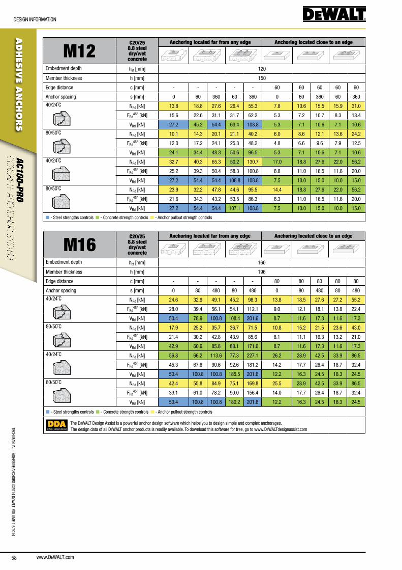
www.DEWALT.com58
TecH ManUal – aDHesIVe ancHoRs ©
2014 DeW
alT VolUMe 1 6/2014
ADHES
IVE A
NCHO
RS
DesIGn InfoRMaTIon
M12C20/25
8.8 steel dry/wetconcrete
Anchoring located far from any edge Anchoring located close to an edge
embedment depth hef [mm] 120
Member thickness h [mm] 150
edge distance c [mm] - - - - - 60 60 60 60 60
anchor spacing s [mm] 0 60 360 60 360 0 60 360 60 360
40/24˚c nRd [kn] 13.8 18.8 27.6 26.4 55.3 7.8 10.6 15.5 15.9 31.0
fRd45° [kn] 15.6 22.6 31.1 31.7 62.2 5.3 7.2 10.7 8.3 13.4
VRd [kn] 27.2 45.2 54.4 63.4 108.8 5.3 7.1 10.6 7.1 10.6
80/50˚c nRd [kn] 10.1 14.3 20.1 21.1 40.2 6.0 8.6 12.1 13.6 24.2
fRd45° [kn] 12.0 17.2 24.1 25.3 48.2 4.8 6.6 9.6 7.9 12.5
VRd [kn] 24.1 34.4 48.3 50.6 96.5 5.3 7.1 10.6 7.1 10.6
40/24˚c nRd [kn] 32.7 40.3 65.3 50.2 130.7 17.0 18.8 27.6 22.0 56.2
fRd45° [kn] 25.2 39.3 50.4 58.3 100.8 8.8 11.0 16.5 11.6 20.0
VRd [kn] 27.2 54.4 54.4 108.8 108.8 7.5 10.0 15.0 10.0 15.0
80/50˚c nRd [kn] 23.9 32.2 47.8 44.6 95.5 14.4 18.8 27.6 22.0 56.2
fRd45° [kn] 21.6 34.3 43.2 53.5 86.3 8.3 11.0 16.5 11.6 20.0
VRd [kn] 27.2 54.4 54.4 107.1 108.8 7.5 10.0 15.0 10.0 15.0
n - steel strengths controls n - concrete strength controls n - anchor pullout strength controls
M16C20/25
8.8 steel dry/wetconcrete
Anchoring located far from any edge Anchoring located close to an edge
embedment depth hef [mm] 160
Member thickness h [mm] 196
edge distance c [mm] - - - - - 80 80 80 80 80
anchor spacing s [mm] 0 80 480 80 480 0 80 480 80 480
40/24˚c nRd [kn] 24.6 32.9 49.1 45.2 98.3 13.8 18.5 27.6 27.2 55.2
fRd45° [kn] 28.0 39.4 56.1 54.1 112.1 9.0 12.1 18.1 13.8 22.4
VRd [kn] 50.4 78.9 100.8 108.4 201.6 8.7 11.6 17.3 11.6 17.3
80/50˚c nRd [kn] 17.9 25.2 35.7 36.7 71.5 10.8 15.2 21.5 23.6 43.0
fRd45° [kn] 21.4 30.2 42.8 43.9 85.6 8.1 11.1 16.3 13.2 21.0
VRd [kn] 42.9 60.6 85.8 88.1 171.6 8.7 11.6 17.3 11.6 17.3
40/24˚c nRd [kn] 56.8 66.2 113.6 77.3 227.1 26.2 28.9 42.5 33.9 86.5
fRd45° [kn] 45.3 67.8 90.6 92.6 181.2 14.2 17.7 26.4 18.7 32.4
VRd [kn] 50.4 100.8 100.8 185.5 201.6 12.2 16.3 24.5 16.3 24.5
80/50˚c nRd [kn] 42.4 55.8 84.9 75.1 169.8 25.5 28.9 42.5 33.9 86.5
fRd45° [kn] 39.1 61.0 78.2 90.0 156.4 14.0 17.7 26.4 18.7 32.4
VRd [kn] 50.4 100.8 100.8 180.2 201.6 12.2 16.3 24.5 16.3 24.5
n - steel strengths controls n - concrete strength controls n - anchor pullout strength controls
DEWALT DESIGN ASSIST
The DeWalT Design assist is a powerful anchor design software which helps you to design simple and complex anchorages.The design data of all DeWalT anchor products is readily available. To download this software for free, go to www.DeWalTdesignassist.com
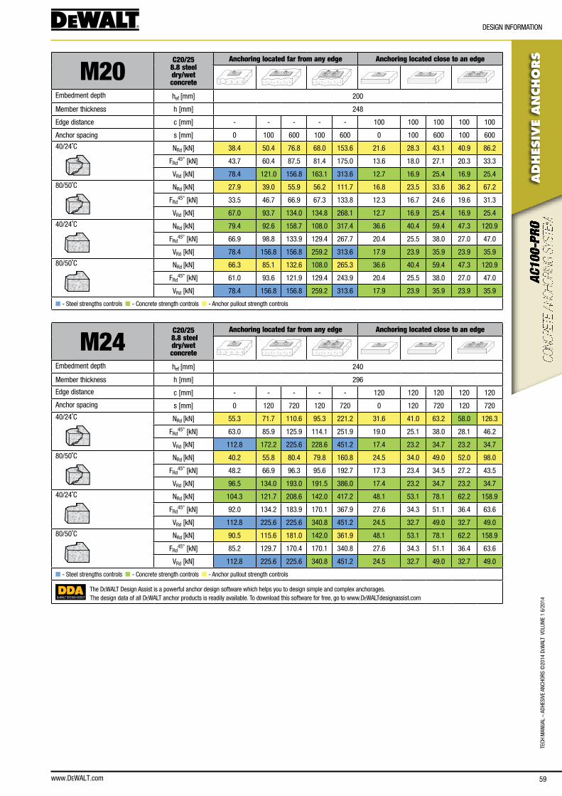
www.DEWALT.com 59
TecH
Man
Ual
– aD
HesI
Ve a
ncHo
Rs ©
2014
DeW
alT
Vol
UMe
1 6/
2014
ADHES
IVE
AN
CHO
RS
DesIGn InfoRMaTIon
M20C20/25
8.8 steel dry/wetconcrete
Anchoring located far from any edge Anchoring located close to an edge
embedment depth hef [mm] 200
Member thickness h [mm] 248
edge distance c [mm] - - - - - 100 100 100 100 100
anchor spacing s [mm] 0 100 600 100 600 0 100 600 100 600
40/24˚c nRd [kn] 38.4 50.4 76.8 68.0 153.6 21.6 28.3 43.1 40.9 86.2
fRd45° [kn] 43.7 60.4 87.5 81.4 175.0 13.6 18.0 27.1 20.3 33.3
VRd [kn] 78.4 121.0 156.8 163.1 313.6 12.7 16.9 25.4 16.9 25.4
80/50˚c nRd [kn] 27.9 39.0 55.9 56.2 111.7 16.8 23.5 33.6 36.2 67.2
fRd45° [kn] 33.5 46.7 66.9 67.3 133.8 12.3 16.7 24.6 19.6 31.3
VRd [kn] 67.0 93.7 134.0 134.8 268.1 12.7 16.9 25.4 16.9 25.4
40/24˚c nRd [kn] 79.4 92.6 158.7 108.0 317.4 36.6 40.4 59.4 47.3 120.9
fRd45° [kn] 66.9 98.8 133.9 129.4 267.7 20.4 25.5 38.0 27.0 47.0
VRd [kn] 78.4 156.8 156.8 259.2 313.6 17.9 23.9 35.9 23.9 35.9
80/50˚c nRd [kn] 66.3 85.1 132.6 108.0 265.3 36.6 40.4 59.4 47.3 120.9
fRd45° [kn] 61.0 93.6 121.9 129.4 243.9 20.4 25.5 38.0 27.0 47.0
VRd [kn] 78.4 156.8 156.8 259.2 313.6 17.9 23.9 35.9 23.9 35.9
n - steel strengths controls n - concrete strength controls n - anchor pullout strength controls
M24C20/25
8.8 steel dry/wetconcrete
Anchoring located far from any edge Anchoring located close to an edge
embedment depth hef [mm] 240
Member thickness h [mm] 296
edge distance c [mm] - - - - - 120 120 120 120 120
anchor spacing s [mm] 0 120 720 120 720 0 120 720 120 720
40/24˚c nRd [kn] 55.3 71.7 110.6 95.3 221.2 31.6 41.0 63.2 58.0 126.3
fRd45° [kn] 63.0 85.9 125.9 114.1 251.9 19.0 25.1 38.0 28.1 46.2
VRd [kn] 112.8 172.2 225.6 228.6 451.2 17.4 23.2 34.7 23.2 34.7
80/50˚c nRd [kn] 40.2 55.8 80.4 79.8 160.8 24.5 34.0 49.0 52.0 98.0
fRd45° [kn] 48.2 66.9 96.3 95.6 192.7 17.3 23.4 34.5 27.2 43.5
VRd [kn] 96.5 134.0 193.0 191.5 386.0 17.4 23.2 34.7 23.2 34.7
40/24˚c nRd [kn] 104.3 121.7 208.6 142.0 417.2 48.1 53.1 78.1 62.2 158.9
fRd45° [kn] 92.0 134.2 183.9 170.1 367.9 27.6 34.3 51.1 36.4 63.6
VRd [kn] 112.8 225.6 225.6 340.8 451.2 24.5 32.7 49.0 32.7 49.0
80/50˚c nRd [kn] 90.5 115.6 181.0 142.0 361.9 48.1 53.1 78.1 62.2 158.9
fRd45° [kn] 85.2 129.7 170.4 170.1 340.8 27.6 34.3 51.1 36.4 63.6
VRd [kn] 112.8 225.6 225.6 340.8 451.2 24.5 32.7 49.0 32.7 49.0
n - steel strengths controls n - concrete strength controls n - anchor pullout strength controls
DEWALT DESIGN ASSIST
The DeWalT Design assist is a powerful anchor design software which helps you to design simple and complex anchorages.The design data of all DeWalT anchor products is readily available. To download this software for free, go to www.DeWalTdesignassist.com
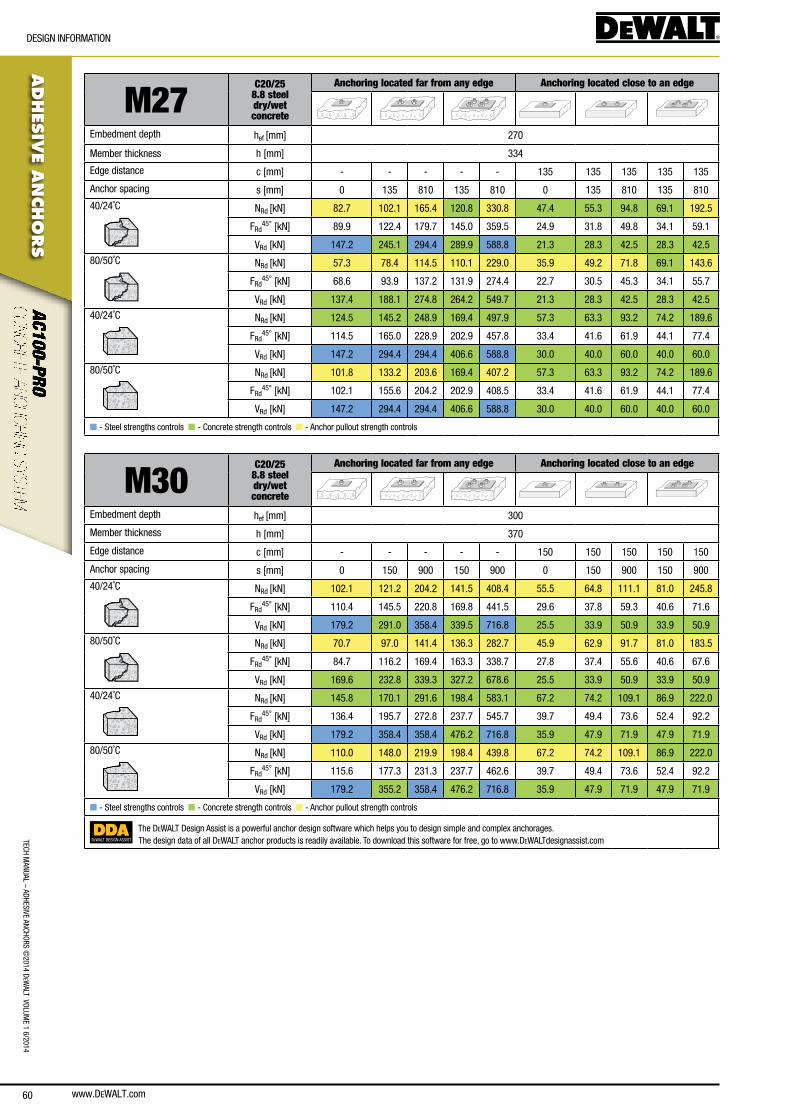
www.DEWALT.com60
TecH ManUal – aDHesIVe ancHoRs ©
2014 DeW
alT VolUMe 1 6/2014
ADHES
IVE A
NCHO
RS
DesIGn InfoRMaTIon
M27C20/25
8.8 steel dry/wetconcrete
Anchoring located far from any edge Anchoring located close to an edge
embedment depth hef [mm] 270
Member thickness h [mm] 334
edge distance c [mm] - - - - - 135 135 135 135 135
anchor spacing s [mm] 0 135 810 135 810 0 135 810 135 810
40/24˚c nRd [kn] 82.7 102.1 165.4 120.8 330.8 47.4 55.3 94.8 69.1 192.5
fRd45° [kn] 89.9 122.4 179.7 145.0 359.5 24.9 31.8 49.8 34.1 59.1
VRd [kn] 147.2 245.1 294.4 289.9 588.8 21.3 28.3 42.5 28.3 42.5
80/50˚c nRd [kn] 57.3 78.4 114.5 110.1 229.0 35.9 49.2 71.8 69.1 143.6
fRd45° [kn] 68.6 93.9 137.2 131.9 274.4 22.7 30.5 45.3 34.1 55.7
VRd [kn] 137.4 188.1 274.8 264.2 549.7 21.3 28.3 42.5 28.3 42.5
40/24˚c nRd [kn] 124.5 145.2 248.9 169.4 497.9 57.3 63.3 93.2 74.2 189.6
fRd45° [kn] 114.5 165.0 228.9 202.9 457.8 33.4 41.6 61.9 44.1 77.4
VRd [kn] 147.2 294.4 294.4 406.6 588.8 30.0 40.0 60.0 40.0 60.0
80/50˚c nRd [kn] 101.8 133.2 203.6 169.4 407.2 57.3 63.3 93.2 74.2 189.6
fRd45° [kn] 102.1 155.6 204.2 202.9 408.5 33.4 41.6 61.9 44.1 77.4
VRd [kn] 147.2 294.4 294.4 406.6 588.8 30.0 40.0 60.0 40.0 60.0
n - steel strengths controls n - concrete strength controls n - anchor pullout strength controls
M30C20/25
8.8 steel dry/wetconcrete
Anchoring located far from any edge Anchoring located close to an edge
embedment depth hef [mm] 300
Member thickness h [mm] 370
edge distance c [mm] - - - - - 150 150 150 150 150
anchor spacing s [mm] 0 150 900 150 900 0 150 900 150 900
40/24˚c nRd [kn] 102.1 121.2 204.2 141.5 408.4 55.5 64.8 111.1 81.0 245.8
fRd45° [kn] 110.4 145.5 220.8 169.8 441.5 29.6 37.8 59.3 40.6 71.6
VRd [kn] 179.2 291.0 358.4 339.5 716.8 25.5 33.9 50.9 33.9 50.9
80/50˚c nRd [kn] 70.7 97.0 141.4 136.3 282.7 45.9 62.9 91.7 81.0 183.5
fRd45° [kn] 84.7 116.2 169.4 163.3 338.7 27.8 37.4 55.6 40.6 67.6
VRd [kn] 169.6 232.8 339.3 327.2 678.6 25.5 33.9 50.9 33.9 50.9
40/24˚c nRd [kn] 145.8 170.1 291.6 198.4 583.1 67.2 74.2 109.1 86.9 222.0
fRd45° [kn] 136.4 195.7 272.8 237.7 545.7 39.7 49.4 73.6 52.4 92.2
VRd [kn] 179.2 358.4 358.4 476.2 716.8 35.9 47.9 71.9 47.9 71.9
80/50˚c nRd [kn] 110.0 148.0 219.9 198.4 439.8 67.2 74.2 109.1 86.9 222.0
fRd45° [kn] 115.6 177.3 231.3 237.7 462.6 39.7 49.4 73.6 52.4 92.2
VRd [kn] 179.2 355.2 358.4 476.2 716.8 35.9 47.9 71.9 47.9 71.9
n - steel strengths controls n - concrete strength controls n - anchor pullout strength controls
DEWALT DESIGN ASSIST
The DeWalT Design assist is a powerful anchor design software which helps you to design simple and complex anchorages.The design data of all DeWalT anchor products is readily available. To download this software for free, go to www.DeWalTdesignassist.com
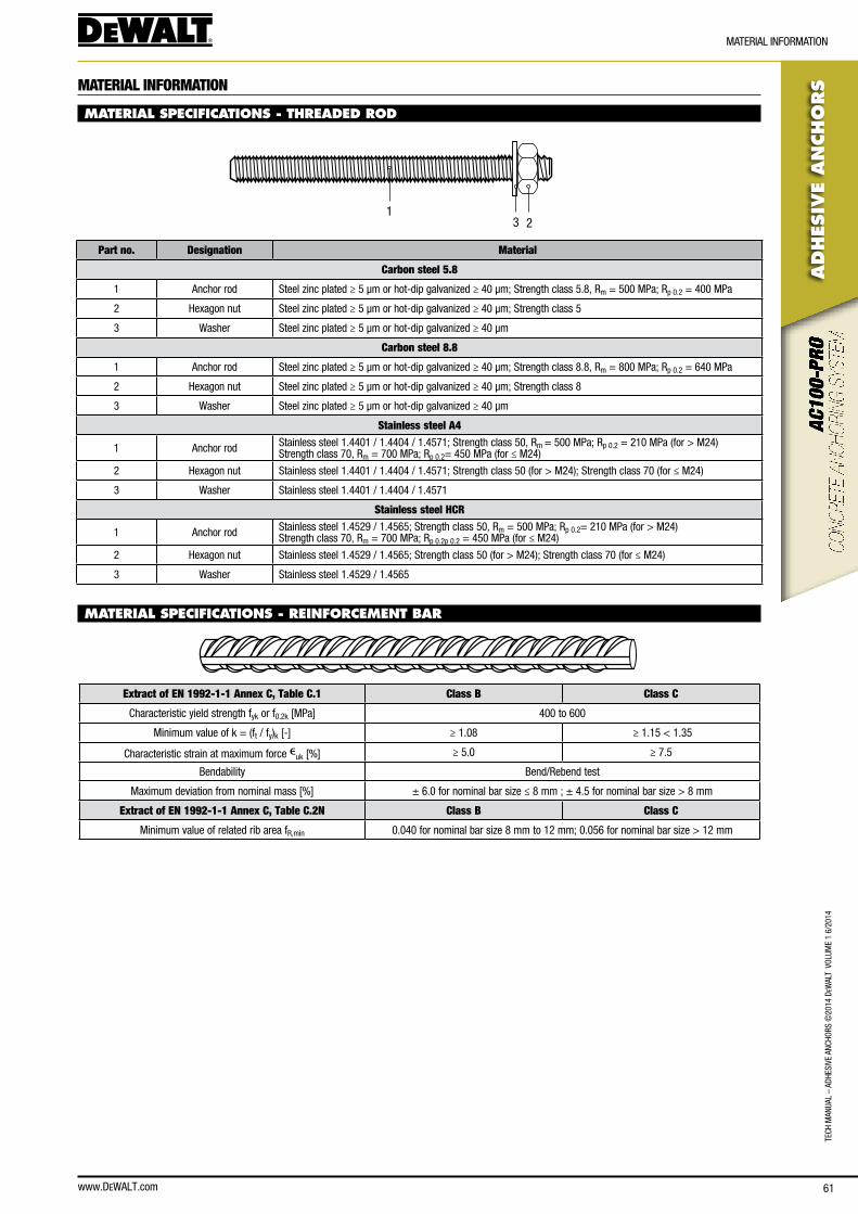
www.DEWALT.com 61
TecH
Man
Ual
– aD
HesI
Ve a
ncHo
Rs ©
2014
DeW
alT
Vol
UMe
1 6/
2014
ADHES
IVE
AN
CHO
RS
MaTeRIal InfoRMaTIon
MATERIAL INFORMATION
MATERIAL SPECIFICATIONS - THREADED ROD
231
Part no. Designation Material
Carbon steel 5.8
1 anchor rod steel zinc plated ≥ 5 μm or hot-dip galvanized ≥ 40 μm; strength class 5.8, Rm = 500 MPa; Rp 0.2 = 400 MPa
2 Hexagon nut steel zinc plated ≥ 5 μm or hot-dip galvanized ≥ 40 μm; strength class 5
3 Washer steel zinc plated ≥ 5 μm or hot-dip galvanized ≥ 40 μm
Carbon steel 8.8
1 anchor rod steel zinc plated ≥ 5 μm or hot-dip galvanized ≥ 40 μm; strength class 8.8, Rm = 800 MPa; Rp 0.2 = 640 MPa
2 Hexagon nut steel zinc plated ≥ 5 μm or hot-dip galvanized ≥ 40 μm; strength class 8
3 Washer steel zinc plated ≥ 5 μm or hot-dip galvanized ≥ 40 μm
Stainless steel A4
1 anchor rod stainless steel 1.4401 / 1.4404 / 1.4571; strength class 50, Rm = 500 MPa; Rp 0.2 = 210 MPa (for > M24)strength class 70, Rm = 700 MPa; Rp 0.2= 450 MPa (for ≤ M24)
2 Hexagon nut stainless steel 1.4401 / 1.4404 / 1.4571; strength class 50 (for > M24); strength class 70 (for ≤ M24)
3 Washer stainless steel 1.4401 / 1.4404 / 1.4571
Stainless steel HCR
1 anchor rod stainless steel 1.4529 / 1.4565; strength class 50, Rm = 500 MPa; Rp 0.2= 210 MPa (for > M24)strength class 70, Rm = 700 MPa; Rp 0.2p 0.2 = 450 MPa (for ≤ M24)
2 Hexagon nut stainless steel 1.4529 / 1.4565; strength class 50 (for > M24); strength class 70 (for ≤ M24)
3 Washer stainless steel 1.4529 / 1.4565
MATERIAL SPECIFICATIONS - REINFORCEMENT BAR
Extract of EN 1992-1-1 Annex C, Table C.1 Class B Class C
characteristic yield strength fyk or f0.2k [MPa] 400 to 600
Minimum value of k = (ft / fy)k [-] ≥ 1.08 ≥ 1.15 < 1.35
characteristic strain at maximum force euk [%] ≥ 5.0 ≥ 7.5
bendability bend/Rebend test
Maximum deviation from nominal mass [%] ± 6.0 for nominal bar size ≤ 8 mm ; ± 4.5 for nominal bar size > 8 mm
Extract of EN 1992-1-1 Annex C, Table C.2N Class B Class C
Minimum value of related rib area fR,min 0.040 for nominal bar size 8 mm to 12 mm; 0.056 for nominal bar size > 12 mm
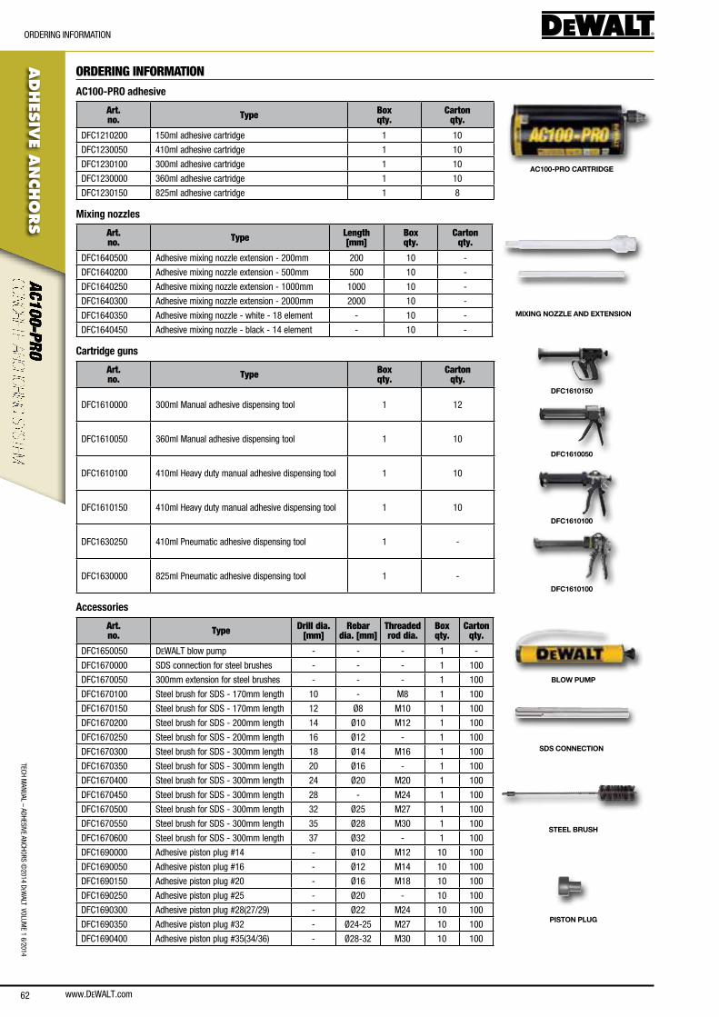
www.DEWALT.com62
TecH ManUal – aDHesIVe ancHoRs ©
2014 DeW
alT VolUMe 1 6/2014
ADHES
IVE A
NCHO
RS
oRDeRInG InfoRMaTIon
ORDERING INFORMATIONAC100-PRO adhesive
Art. no. Type Box
qty.Carton
qty.
Dfc1210200 150ml adhesive cartridge 1 10
Dfc1230050 410ml adhesive cartridge 1 10
Dfc1230100 300ml adhesive cartridge 1 10
Dfc1230000 360ml adhesive cartridge 1 10
Dfc1230150 825ml adhesive cartridge 1 8
AC100-PRO CARTRIDGE
Mixing nozzles
Art. no. Type Length
[mm]Box qty.
Carton qty.
Dfc1640500 adhesive mixing nozzle extension - 200mm 200 10 -
Dfc1640200 adhesive mixing nozzle extension - 500mm 500 10 -
Dfc1640250 adhesive mixing nozzle extension - 1000mm 1000 10 -
Dfc1640300 adhesive mixing nozzle extension - 2000mm 2000 10 -
Dfc1640350 adhesive mixing nozzle - white - 18 element - 10 -
Dfc1640450 adhesive mixing nozzle - black - 14 element - 10 -
MIXING NOZZLE AND EXTENSION
Cartridge guns
Art. no. Type Box
qty.Carton
qty.
Dfc1610000 300ml Manual adhesive dispensing tool 1 12
Dfc1610050 360ml Manual adhesive dispensing tool 1 10
Dfc1610100 410ml Heavy duty manual adhesive dispensing tool 1 10
Dfc1610150 410ml Heavy duty manual adhesive dispensing tool 1 10
Dfc1630250 410ml Pneumatic adhesive dispensing tool 1 -
Dfc1630000 825ml Pneumatic adhesive dispensing tool 1 -
DFC1610150
DFC1610050
DFC1610100
DFC1610100
Accessories
Art. no. Type Drill dia.
[mm]Rebar
dia. [mm]Threaded rod dia.
Box qty.
Carton qty.
Dfc1650050 DeWalT blow pump - - - 1 -
Dfc1670000 sDs connection for steel brushes - - - 1 100
Dfc1670050 300mm extension for steel brushes - - - 1 100
Dfc1670100 steel brush for sDs - 170mm length 10 - M8 1 100
Dfc1670150 steel brush for sDs - 170mm length 12 Ø8 M10 1 100
Dfc1670200 steel brush for sDs - 200mm length 14 Ø10 M12 1 100
Dfc1670250 steel brush for sDs - 200mm length 16 Ø12 - 1 100
Dfc1670300 steel brush for sDs - 300mm length 18 Ø14 M16 1 100
Dfc1670350 steel brush for sDs - 300mm length 20 Ø16 - 1 100
Dfc1670400 steel brush for sDs - 300mm length 24 Ø20 M20 1 100
Dfc1670450 steel brush for sDs - 300mm length 28 - M24 1 100
Dfc1670500 steel brush for sDs - 300mm length 32 Ø25 M27 1 100
Dfc1670550 steel brush for sDs - 300mm length 35 Ø28 M30 1 100
Dfc1670600 steel brush for sDs - 300mm length 37 Ø32 - 1 100
Dfc1690000 adhesive piston plug #14 - Ø10 M12 10 100
Dfc1690050 adhesive piston plug #16 - Ø12 M14 10 100
Dfc1690150 adhesive piston plug #20 - Ø16 M18 10 100
Dfc1690250 adhesive piston plug #25 - Ø20 - 10 100
Dfc1690300 adhesive piston plug #28(27/29) - Ø22 M24 10 100
Dfc1690350 adhesive piston plug #32 - Ø24-25 M27 10 100
Dfc1690400 adhesive piston plug #35(34/36) - Ø28-32 M30 10 100
BLOW PUMP
SDS CONNECTION
STEEL BRUSH
PISTON PLUG

www.DEWALT.com 63
ADHES
IVE
AN
CHO
RS
oRDeRInG InfoRMaTIon
TecH
Man
Ual
– aD
HesI
Ve a
ncHo
Rs ©
2014
DeW
alT
Vol
UMe
1 6/
2014
Chisel point threaded rods
Art. no. Type Drill dia.
[mm]Thread Size
[mm]Box qty.
Carton qty.
Dfc4130000 Zinc plated class 5.8 steel 110mm 10 M8 10 200
Dfc4130050 Zinc plated class 5.8 steel 130mm 12 M10 10 200
Dfc4130100 Zinc plated class 5.8 steel 160mm 14 M12 10 100
Dfc4130150 Zinc plated class 5.8 steel 190mm 18 M16 10 80
Dfc4130200 Zinc plated class 5.8 steel 260mm 24 M20 5 25
Dfc4130250 Zinc plated class 5.8 steel 300mm 28 M24 5 20
Dfc4150000 a4 stainless steel 110mm 10 M8 10 200
Dfc4150050 a4 stainless steel 130mm 12 M10 10 200
Dfc4150100 a4 stainless steel 160mm 14 M12 10 100
Dfc4150150 a4 stainless steel 190mm 18 M16 10 80
Dfc4150200 a4 stainless steel 260mm 24 M20 5 25
Dfc4150250 a4 stainless steel 300mm 28 M24 5 20
Straight cut threaded rods
Art. no. Type Drill dia.
[mm]Thread Size
[mm]Box qty.
Carton qty.
Dfc4170000 Hot dipped galvanized 110mm 10 M8 25 200
Dfc4170040 Hot dipped galvanized 130mm 12 M10 25 100
Dfc4170160 Hot dipped galvanized 160mm 14 M12 10 100
Dfc4170200 Hot dipped galvanized 190mm 18 M16 10 40
Dfc4170320 Hot dipped galvanized 260mm 24 M20 10 40
Dfc4170400 Hot dipped galvanized 290mm 28 M24 10 40
ZINC PLATED CLASS 5.8 STEEL
A4 STAINLESS STEEL
HOT DIPPED GALVANIZED
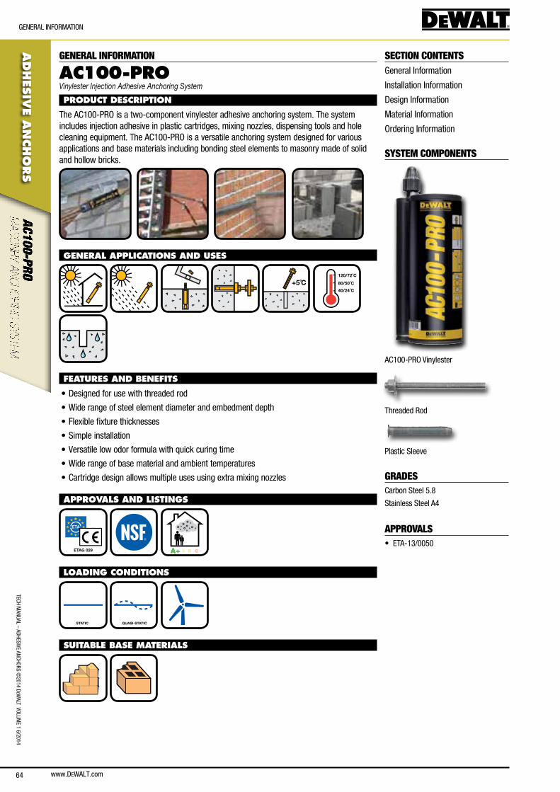
www.DEWALT.com64
TecH ManUal – aDHesIVe ancHoRs ©
2014 DeW
alT VolUMe 1 6/2014
ADHES
IVE A
NCHO
RS
GeneRal InfoRMaTIon
SECTION CONTENTSGeneral Information
Installation Information
Design Information
Material Information
ordering Information
SYSTEM COMPONENTS
ac100-PRo Vinylester
Threaded Rod
Plastic sleeve
GRADEScarbon steel 5.8
stainless steel a4
APPROVALS• eTa-13/0050
GENERAL INFORMATION
AC100-PROVinylester Injection Adhesive Anchoring System
PRODUCT DESCRIPTION
The ac100-PRo is a two-component vinylester adhesive anchoring system. The system includes injection adhesive in plastic cartridges, mixing nozzles, dispensing tools and hole cleaning equipment. The ac100-PRo is a versatile anchoring system designed for various applications and base materials including bonding steel elements to masonry made of solid and hollow bricks.
GENERAL APPLICATIONS AND USES
+5˚C
40/24˚C
80/50˚C
120/72˚C
FEATURES AND BENEFITS
• Designed for use with threaded rod
• Wide range of steel element diameter and embedment depth
• flexible fixture thicknesses
• simple installation
• Versatile low odor formula with quick curing time
• Wide range of base material and ambient temperatures
• cartridge design allows multiple uses using extra mixing nozzles
APPROVALS AND LISTINGS
ETAG 029 A+ A B C
LOADING CONDITIONS
STATIC QUASI-STATIC
SUITABLE BASE MATERIALS
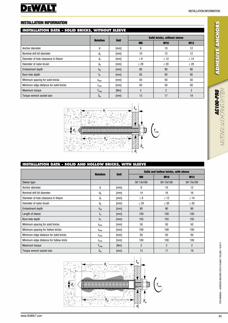
www.DEWALT.com 65
ADHES
IVE
AN
CHO
RS
InsTallaTIon InfoRMaTIon
TecH
Man
Ual
– aD
HesI
Ve a
ncHo
Rs ©
2014
DeW
alT
Vol
UMe
1 6/
2014
INSTALLATION INFORMATION
INSTALLATION DATA - SOLID BRICKS, WITHOUT SLEEVE
Notation UnitSolid bricks, without sleeve
M8 M10 M12
anchor diameter d [mm] 8 10 12
nominal drill bit diameter d0 [mm] 10 12 12
Diameter of hole clearance in fixture df [mm] ≤ 9 ≤ 12 ≤ 14
Diameter of nylon brush db [mm] ≥ 20 ≥ 20 ≥ 20
embedment depth hef [mm] 80 90 90
bore hole depth h1 [mm] 85 95 95
Minimum spacing for solid bricks smin [mm] 50 50 50
Minimum edge distance for solid bricks cmin [mm] 50 50 50
Maximum torque Tmax [nm] 2 2 2
Torque wrench socket size sw [mm] 13 17 19
h1
hef
d0
Sw
Tmax
df
tfix
INSTALLATION DATA - SOLID AND HOLLOW BRICKS, WITH SLEEVE
Notation UnitSolid and hollow bricks, with sleeve
M8 M10 M12
sleeve type sH 13x100 sH 15x100 sH 15x100
anchor diameter d [mm] 8 10 12
nominal drill bit diameter d0 [mm] 14 16 16
Diameter of hole clearance in fixture df [mm] ≤ 9 ≤ 12 ≤ 14
Diameter of nylon brush db [mm] ≥ 20 ≥ 20 ≥ 20
embedment depth hef [mm] 80 90 90
length of sleeve ℓs [mm] 100 100 100
bore hole depth h1 [mm] 105 105 105
Minimum spacing for solid bricks smin [mm] 50 50 50
Minimum spacing for hollow bricks smin [mm] 100 100 100
Minimum edge distance for solid bricks cmin [mm] 50 50 50
Minimum edge distance for hollow brick cmin [mm] 100 100 100
Maximum torque Tmax [nm] 2 2 2
Torque wrench socket size sw [mm] 13 17 19
h1
hef
d0
Sw
Tmax
df
tfix
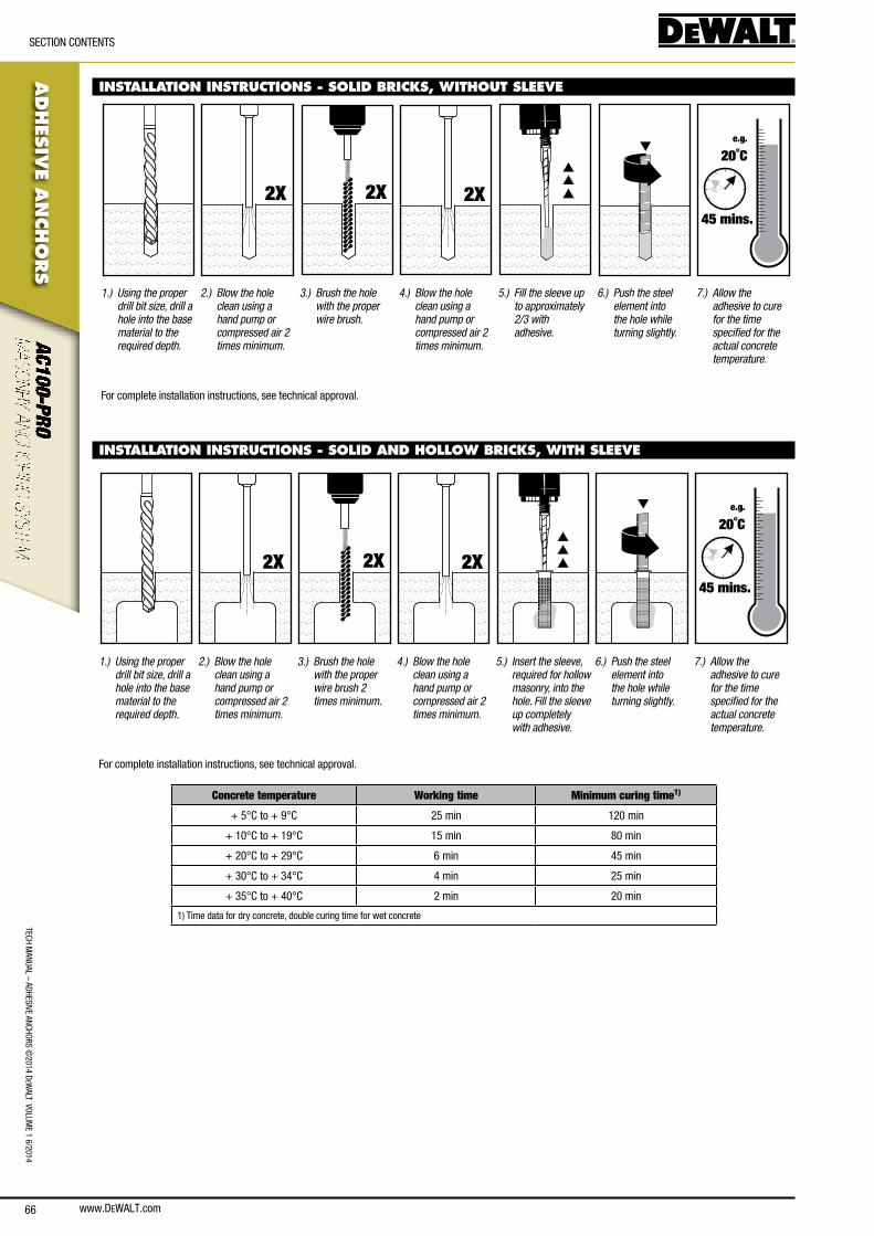
www.DEWALT.com66
TecH ManUal – aDHesIVe ancHoRs ©
2014 DeW
alT VolUMe 1 6/2014
ADHES
IVE A
NCHO
RS
secTIon conTenTs
INSTALLATION INSTRUCTIONS - SOLID BRICKS, WITHOUT SLEEVE
2X 2X 2X
e.g.
20˚C
45 mins.
1.) Using the proper drill bit size, drill a hole into the base material to the required depth.
2.) Blow the hole clean using a hand pump or compressed air 2 times minimum.
3.) Brush the hole with the proper wire brush.
4.) Blow the hole clean using a hand pump or compressed air 2 times minimum.
5.) Fill the sleeve up to approximately 2/3 with adhesive.
6.) Push the steel element into the hole while turning slightly.
7.) Allow the adhesive to cure for the time specified for the actual concrete temperature.
for complete installation instructions, see technical approval.
INSTALLATION INSTRUCTIONS - SOLID BRICKS, WITHOUT SLEEVE
INSTALLATION INSTRUCTIONS - SOLID AND HOLLOW BRICKS, WITH SLEEVE
2X 2X 2X
e.g.
20˚C
45 mins.
1.) Using the proper drill bit size, drill a hole into the base material to the required depth.
2.) Blow the hole clean using a hand pump or compressed air 2 times minimum.
3.) Brush the hole with the proper wire brush 2 times minimum.
4.) Blow the hole clean using a hand pump or compressed air 2 times minimum.
5.) Insert the sleeve, required for hollow masonry, into the hole. Fill the sleeve up completely with adhesive.
6.) Push the steel element into the hole while turning slightly.
7.) Allow the adhesive to cure for the time specified for the actual concrete temperature.
for complete installation instructions, see technical approval.
Concrete temperature Working time Minimum curing time1)
+ 5°c to + 9°c 25 min 120 min
+ 10°c to + 19°c 15 min 80 min
+ 20°c to + 29°c 6 min 45 min
+ 30°c to + 34°c 4 min 25 min
+ 35°c to + 40°c 2 min 20 min
1) Time data for dry concrete, double curing time for wet concrete
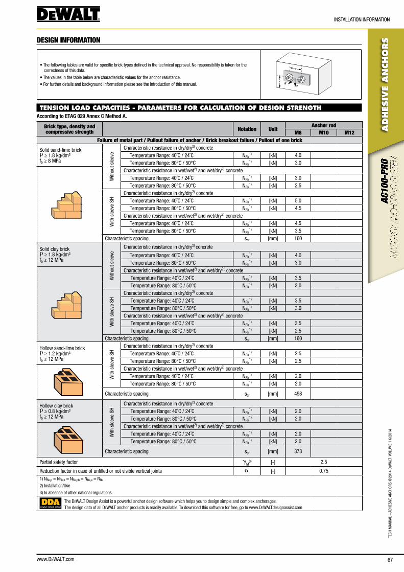
www.DEWALT.com 67
TecH
Man
Ual
– aD
HesI
Ve a
ncHo
Rs ©
2014
DeW
alT
Vol
UMe
1 6/
2014
ADHES
IVE
AN
CHO
RS
InsTallaTIon InfoRMaTIon
DESIGN INFORMATION
• The following tables are valid for specific brick types defined in the technical approval. no responsibility is taken for the correctness of this data.
• The values in the table below are characteristic values for the anchor resistance.
• for further details and background information please see the introduction of this manual. NV
s
c
TENSION LOAD CAPACITIES - PARAMETERS FOR CALCULATION OF DESIGN STRENGTHAccording to ETAG 029 Annex C Method A.
Brick type, density and compressive strength Notation Unit
Anchor rodM8 M10 M12
Failure of metal part / Pullout failure of anchor / Brick breakout failure / Pullout of one brick
solid sand-lime brickr ≥ 1.8 kg/dm³fb ≥ 8 MPa
With
out s
leev
e
characteristic resistance in dry/dry2) concrete Temperature Range: 40˚c / 24˚c nRk
1) [kn] 4.0 Temperature Range: 80°c / 50°c nRk
1) [kn] 3.0characteristic resistance in wet/wet2) and wet/dry2) concrete Temperature Range: 40˚c / 24˚c nRk
1) [kn] 3.0 Temperature Range: 80°c / 50°c nRk
1) [kn] 2.5
With
sle
eve
sH
characteristic resistance in dry/dry2) concrete Temperature Range: 40˚c / 24˚c nRk
1) [kn] 5.0 Temperature Range: 80°c / 50°c nRk
1) [kn] 4.5characteristic resistance in wet/wet2) and wet/dry2) concrete Temperature Range: 40˚c / 24˚c nRk
1) [kn] 4.5 Temperature Range: 80°c / 50°c nRk
1) [kn] 3.5characteristic spacing scr [mm] 160
solid clay brickr ≥ 1.8 kg/dm³fb ≥ 12 MPa
With
out s
leev
e
characteristic resistance in dry/dry2) concrete
Temperature Range: 40˚c / 24˚c nRk1) [kn] 4.0
Temperature Range: 80°c / 50°c nRk1) [kn] 3.0
characteristic resistance in wet/wet2) and wet/dry2 ) concrete Temperature Range: 40˚c / 24˚c nRk
1) [kn] 3.5 Temperature Range: 80°c / 50°c nRk
1) [kn] 3.0
With
sle
eve
sH
characteristic resistance in dry/dry2) concrete Temperature Range: 40˚c / 24˚c nRk
1) [kn] 3.5 Temperature Range: 80°c / 50°c nRk
1) [kn] 3.0characteristic resistance in wet/wet2) and wet/dry2) concrete Temperature Range: 40˚c / 24˚c nRk
1) [kn] 3.5 Temperature Range: 80°c / 50°c nRk
1) [kn] 2.5characteristic spacing scr [mm] 160
Hollow sand-lime brickr ≥ 1.2 kg/dm³fb ≥ 12 MPa
With
sle
eve
sH
characteristic resistance in dry/dry2) concrete Temperature Range: 40˚c / 24˚c nRk
1) [kn] 2.5 Temperature Range: 80°c / 50°c nRk
1) [kn] 2.5characteristic resistance in wet/wet2) and wet/dry2) concrete Temperature Range: 40˚c / 24˚c nRk
1) [kn] 2.0 Temperature Range: 80°c / 50°c nRk
1) [kn] 2.0
characteristic spacing scr [mm] 498
Hollow clay brickr ≥ 0.8 kg/dm³fb ≥ 12 MPa
With
sle
eve
sH
characteristic resistance in dry/dry2) concrete Temperature Range: 40˚c / 24˚c nRk
1) [kn] 2.0 Temperature Range: 80°c / 50°c nRk
1) [kn] 2.0characteristic resistance in wet/wet2) and wet/dry2) concrete Temperature Range: 40˚c / 24˚c nRk
1) [kn] 2.0 Temperature Range: 80°c / 50°c nRk
1) [kn] 2.0
characteristic spacing scr [mm] 373
Partial safety factor gM
3) [-] 2.5
Reduction factor in case of unfilled or not visible vertical joints aj [-] 0.75
1) nRk,p = nRk,b = nRk,pb = nRk,s = nRk
2) Installation/Use
3) In absence of other national regulations
DEWALT DESIGN ASSIST
The DeWalT Design assist is a powerful anchor design software which helps you to design simple and complex anchorages.The design data of all DeWalT anchor products is readily available. To download this software for free, go to www.DeWalTdesignassist.com
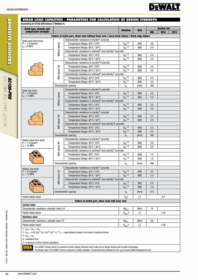
www.DEWALT.com68
TecH ManUal – aDHesIVe ancHoRs ©
2014 DeW
alT VolUMe 1 6/2014
ADHES
IVE A
NCHO
RS
DesIGn InfoRMaTIon
SHEAR LOAD CAPACITIES - PARAMETERS FOR CALCULATION OF DESIGN STRENGTHAccording to ETAG 029 Annex C Method A.
Brick type, density and compressive strength Notation Unit
Anchor rodM8 M10 M12
Failure of metal part, shear load without lever arm / Local brick failure / Brick edge failure
solid sand-lime brickr ≥ 1.8 kg/dm³fb ≥ 8 MPa
With
out s
leev
e
characteristic resistance in dry/dry4) concrete
Temperature Range: 40˚c / 24˚c VRk1,2) [kn] 4.0
Temperature Range: 80°c / 50°c VRk1,2) [kn] 3.0
characteristic resistance in wet/wet4) and wet/dry4) concrete
Temperature Range: 40˚c / 24˚c VRk1,2) [kn] 3.0
Temperature Range: 80°c / 50°c VRk1,2) [kn] 2.5
With
sle
eve
sH
characteristic resistance in dry/dry4)) concrete
Temperature Range: 40˚c / 24˚c VRk1,2) [kn] 5.0
Temperature Range: 80°c / 50°c VRk1,2) [kn] 4.5
characteristic resistance in wet/wet4) and wet/dry4) concrete
Temperature Range: 40˚c / 24˚c VRk1,2) [kn] 4.5
Temperature Range: 80°c / 50°c VRk1,2) [kn] 3.5
characteristic spacing scr [mm] 160
solid clay brickr ≥ 1.8 kg/dm³fb ≥ 12 MPa
With
out s
leev
e
characteristic resistance in dry/dry4)) concrete
Temperature Range: 40˚c / 24˚c VRk1,2) [kn] 4.0
Temperature Range: 80°c / 50°c VRk1,2) [kn] 3.0
characteristic resistance in wet/wet4) and wet/dry4) concrete
Temperature Range: 40˚c / 24˚c VRk1,2) [kn] 3.5
Temperature Range: 80°c / 50°c VRk1,2) [kn] 3.0
With
sle
eve
sH
characteristic resistance in dry/dry4) concrete
Temperature Range: 40˚c / 24˚c VRk1,2) [kn] 3.5
Temperature Range: 80°c / 50°c VRk1,2) [kn] 3.0
characteristic resistance in wet/wet4) and wet/dry4)) concrete
Temperature Range: 40˚c / 24˚c VRk1,2) [kn] 3.5
Temperature Range: 80°c / 50°c VRk1,2) [kn] 2.5
characteristic spacing scr [mm] 160
Hollow sand-lime brickr ≥ 1.2 kg/dm³fb ≥ 12 MPa
With
sle
eve
sH
characteristic resistance in dry/dry4) concrete
Temperature Range: 40˚c / 24˚c VRk1,3) [kn] 2.0
Temperature Range: 80°c / 50°c VRk1,3) [kn] 2.0
characteristic resistance in wet/wet4) and wet/dry4) concrete
Temperature Range: 40˚c / 24˚c VRk1,3) [kn] 1.5
Temperature Range: 80°c / 50°c VRk1,3) [kn] 1.5
characteristic spacing scr [mm] 498
Hollow clay brickr ≥ 0.8 kg/dm³fb ≥ 12 MPa
With
sle
eve
sH
characteristic resistance in dry/dry4) concrete
Temperature Range: 40˚c / 24˚c VRk1,3) [kn] 2.0
Temperature Range: 80°c / 50°c VRk1,3) [kn] 2.0
characteristic resistance in wet/wet4) and wet/dry4) concrete
Temperature Range: 40˚c / 24˚c VRk1,3) [kn] 2.0
Temperature Range: 80°c / 50°c VRk1,3) [kn] 2.0
characteristic spacing scr [mm] 373
Partial safety factor gM
5) [-] 2.5
Failure of metal part, shear load with lever arm Carbon steelcharacteristic resistance, strength class 5.8 MRk,s [nm] 19
Partial safety factor gMs,v
5) [-] 1.25
Stainless steelcharacteristic resistance, strength class 70 MRk,s [nm] 26
Partial safety factor gMs,v
5) [-] 1.56
1) VRk,b = VRk,s = VRk
2 ) VRk,c = 0.45 (d0)0.5 (hef / d0)0.2 (fb)0.5 c11.5; c1 = edge distance closest to the edge in loading direction
3 ) VRk,c = VRk
4) Installation/Use
5 ) In absence of other national regulations
DEWALT DESIGN ASSIST
The DeWalT Design assist is a powerful anchor design software which helps you to design simple and complex anchorages.The design data of all DeWalT anchor products is readily available. To download this software for free, go to www.DeWalTdesignassist.com
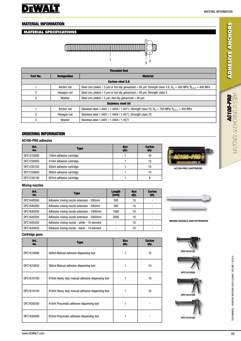
www.DEWALT.com 69
TecH
Man
Ual
– aD
HesI
Ve a
ncHo
Rs ©
2014
DeW
alT
Vol
UMe
1 6/
2014
ADHES
IVE
AN
CHO
RS
MaTeRIal InfoRMaTIon
MATERIAL INFORMATION
MATERIAL SPECIFICATIONS
231
Threaded Rod
Part No. Designation Material
Carbon steel 5.8
1 anchor rod steel zinc plated ≥ 5 µm or hot-dip galvanized ≥ 40 µm; strength class 5.8, Rm = 500 MPa; Rp 0.2 = 400 MPa
2 Hexagon nut steel zinc plated ≥ 5 μm or hot-dip galvanized ≥ 40 μm; strength class 5
3 Washer steel zinc plated ≥ 5 μm; Hot-dip galvanized ≥ 40 μm
Stainless steel A4
1 anchor rod stainless steel 1.4401 / 1.4404 / 1.4571; strength class 70, Rm = 700 MPa; Rp 0.2 = 450 MPa
2 Hexagon nut stainless steel 1.4401 / 1.4404 / 1.4571; strength class 70
3 Washer stainless steel 1.4401 / 1.4404 / 1.4571
ORDERING INFORMATIONAC100-PRO adhesive
Art. no. Type Box
qty.Carton
qty.
Dfc1210200 150ml adhesive cartridge 1 10
Dfc1230050 410ml adhesive cartridge 1 10
Dfc1230100 300ml adhesive cartridge 1 10
Dfc1230000 360ml adhesive cartridge 1 10
Dfc1230150 825ml adhesive cartridge 1 8
AC100-PRO CARTRIDGE
Mixing nozzles
Art. no. Type Length
[mm]Box qty.
Carton qty.
Dfc1640500 adhesive mixing nozzle extension - 200mm 200 10 -
Dfc1640200 adhesive mixing nozzle extension - 500mm 500 10 -
Dfc1640250 adhesive mixing nozzle extension - 1000mm 1000 10 -
Dfc1640300 adhesive mixing nozzle extension - 2000mm 2000 10 -
Dfc1640350 adhesive mixing nozzle - white - 18 element - 10 -
Dfc1640450 adhesive mixing nozzle - black - 14 element - 10 -
MIXING NOZZLE AND EXTENSION
Cartridge guns
Art. no. Type Box
qty.Carton
qty.
Dfc1610000 300ml Manual adhesive dispensing tool 1 12
Dfc1610050 360ml Manual adhesive dispensing tool 1 10
Dfc1610100 410ml Heavy duty manual adhesive dispensing tool 1 10
Dfc1610150 410ml Heavy duty manual adhesive dispensing tool 1 10
Dfc1630250 410ml Pneumatic adhesive dispensing tool 1 -
Dfc1630000 825ml Pneumatic adhesive dispensing tool 1 -
DFC1610150
DFC1610050
DFC1610100
DFC1610100

70
TecH ManUal – aDHesIVe ancHoRs ©
2014 DeW
alT VolUMe 1 6/2014
ADHES
IVE A
NCHO
RS
oRDeRInG InfoRMaTIon
www.DeWalT.com
Accessories
Art. no. Type Drill dia.
[mm]Anchor
dia.Box qty.
Carton qty.
Dfc1650050 DeWalT blow pump - - 1 -
Dfc1660000 nylon brush drill hole cleaner 8 - 10 - 1 100
Dfc1660050 nylon brush drill hole cleaner 10 - 14 - 1 100
Dfc1660100 nylon brush drill hole cleaner 16 - 28 - 1 100
Dfc4720000 13mmx100mm PRo plastic sleeve (ac100PRo) - M8 10 -
Dfc4720050 15mmx100mm PRo plastic sleeve (ac100PRo) - M10 - M12 10 -
Dfc4730000 11 x 1000 mesh sleeve - M8 1 10
Dfc4730050 15 x 1000 mesh sleeve - M10 - M12 1 10
Dfc4730100 20 x 1000 mesh sleeve - M16 - M18 1 10
BLOW PUMP
NYLON BRUSHES
PLASTIC SLEEVE
PRO PLASTIC SLEEVE
MESH SLEEVE
Chisel point threaded rods
Art. no. Type Drill dia.
[mm]Thread Size
[mm]Box qty.
Carton qty.
Dfc4130000 Zinc plated class 5.8 steel 110mm 10 M8 10 200
Dfc4130050 Zinc plated class 5.8 steel 130mm 12 M10 10 200
Dfc4130100 Zinc plated class 5.8 steel 160mm 14 M12 10 100
Dfc4150000 a4 stainless steel 110mm 10 M8 10 200
Dfc4150050 a4 stainless steel 130mm 12 M10 10 200
Dfc4150100 a4 stainless steel 160mm 14 M12 10 100
Straight cut threaded rods
Art. no. Type Drill dia.
[mm]Thread Size
[mm]Box qty.
Carton qty.
Dfc4170000 Hot dipped galvanized 110mm 10 M8 25 200
Dfc4170040 Hot dipped galvanized 130mm 12 M10 25 100
Dfc4170160 Hot dipped galvanized 160mm 14 M12 10 100
ZINC PLATED CLASS 5.8 STEEL
A4 STAINLESS STEEL
HOT DIPPED GALVANIZED
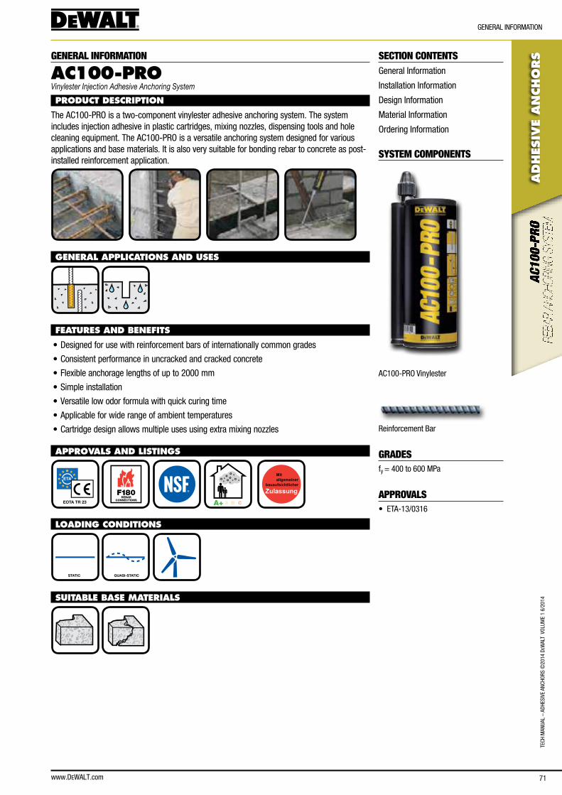
www.DEWALT.com 71
TecH
Man
Ual
– aD
HesI
Ve a
ncHo
Rs ©
2014
DeW
alT
Vol
UMe
1 6/
2014
ADHES
IVE
AN
CHO
RS
GeneRal InfoRMaTIon
SECTION CONTENTSGeneral Information
Installation Information
Design Information
Material Information
ordering Information
SYSTEM COMPONENTS
ac100-PRo Vinylester
Reinforcement bar
GRADESfy = 400 to 600 MPa
APPROVALS• eTa-13/0316
GENERAL INFORMATION
AC100-PROVinylester Injection Adhesive Anchoring System
PRODUCT DESCRIPTION
The ac100-PRo is a two-component vinylester adhesive anchoring system. The system includes injection adhesive in plastic cartridges, mixing nozzles, dispensing tools and hole cleaning equipment. The ac100-PRo is a versatile anchoring system designed for various applications and base materials. It is also very suitable for bonding rebar to concrete as post-installed reinforcement application.
GENERAL APPLICATIONS AND USES
FEATURES AND BENEFITS
• Designed for use with reinforcement bars of internationally common grades
• consistent performance in uncracked and cracked concrete
• flexible anchorage lengths of up to 2000 mm
• simple installation
• Versatile low odor formula with quick curing time
• applicable for wide range of ambient temperatures
• cartridge design allows multiple uses using extra mixing nozzles
APPROVALS AND LISTINGS
EOTA TR 23 F180
REBARCONNECTIONS
A+ A B C
LOADING CONDITIONS
STATIC QUASI-STATIC
SUITABLE BASE MATERIALS

72
ADHES
IVE A
NCHO
RS
TecH ManUal – aDHesIVe ancHoRs ©
2014 DeW
alT VolUMe 1 6/2014
www.DeWalT.com
InsTallaTIon InfoRMaTIon
INSTALLATION INFORMATION
INSTALLATION DATA - POST INSTALLED REBAR
Notation UnitPost-installed reinforcement bar
Ø8 Ø10 Ø12 Ø14 Ø16 Ø20 Ø22 Ø24 Ø25
Diameter of reinforcement bar ds [mm] 8 10 12 14 16 20 22 24 25
nominal drill bit diameter d0 [mm] 12 14 16 18 20 25 28 32 32
Diameter of brush db [mm] 14 16 18 20 22 27 30 34 34
embedment depth ℓv [mm] as given below
Minimum spacingsmin
Minimum concrete cover cmin
Drilling method Rebar diameter Without drilling aid With drilling aid
≥ 5 ds≥ 50 mm
Hammer drilling< 25 mm 30 mm + 0.06 · ℓv ≥ 2 ds 30 mm + 0.02 · ℓv ≥ 2 ds
= 25 mm 40 mm + 0.06 · ℓv ≥ 2 ds 40 mm + 0.02 · ℓv ≥ 2 ds
compressed air drilling< 25 mm 50 mm + 0.08 · ℓv 50 mm + 0.02 · ℓv
= 25 mm 60 mm + 0.08 · ℓv 60 mm + 0.02 · ℓv
hef
d0
h1
Concrete temperature Working time Minimum curing time1)
0°c to + 4°c 45 min 7 h
+ 5°c to + 9°c 25 min 2 h
+ 10°c to + 19°c 15 min 80 min
+ 20°c to + 24°c 6 min 45 min
+ 25°c to + 29°c 4 min 25 min
+ 30°c to + 40°c 2.5 min 15 min
1) Time data for dry concrete, double curing time for wet concrete
INSTALLATION INSTRUCTIONS
4X 4X 4X
e.g.
20˚C
45 mins.
1.) Using the proper drill bit size, drill a hole into the base material to the required depth.
2.) Blow the hole clean using a hand pump or compressed air 4 times minimum.
3.) Brush the hole with the proper wire brush 4 times minimum.
4.) Blow the hole clean using a hand pump or compressed air 4 times minimum.
5.) Fill the hole up to approximately 2/3 with adhesive.
6.) Push the rebar into the hole while turning slightly.
7.) Allow the adhesive to cure for the time specified for the actual concrete temperature prior to applying any load.
for complete installation instructions, see technical approval.
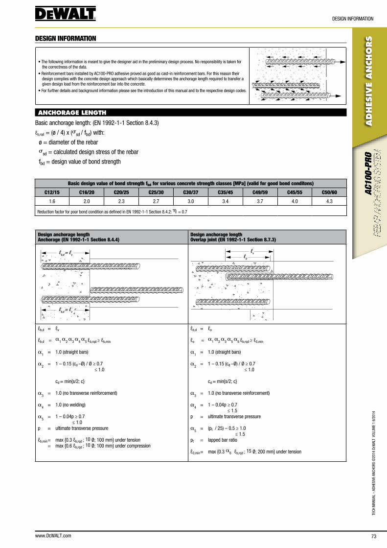
www.DEWALT.com 73
TecH
Man
Ual
– aD
HesI
Ve a
ncHo
Rs ©
2014
DeW
alT
Vol
UMe
1 6/
2014
ADHES
IVE
AN
CHO
RS
DesIGn InfoRMaTIon
DESIGN INFORMATION
• The following information is meant to give the designer aid in the preliminary design process. no responsibility is taken for the correctness of the data.
• Reinforcement bars installed by ac100-PRo adhesive proved as good as cast-in reinforcement bars. for this reason their design complies with the concrete design approach which basically determines the anchorage length required to transfer a given design load from the reinforcement bar into the concrete.
• for further details and background information please see the introduction of this manual and to the respective design codes.
ANCHORAGE LENGTH
basic anchorage length: (en 1992-1-1 section 8.4.3)
ℓb,rqd = (ø / 4) x (ssd / fbd) with:
ø = diameter of the rebar ssd = calculated design stress of the rebar
fbd = design value of bond strength
Basic design value of bond strength fbd for various concrete strength classes [MPa] (valid for good bond conditons)
C12/15 C16/20 C20/25 C25/30 C30/37 C35/45 C49/59 C45/55 C50/60
1.6 2.0 2.3 2.7 3.0 3.4 3.7 4.0 4.3
Reduction factor for poor bond condition as defined in en 1992-1-1 section 8.4.2: h = 0.7
Design anchorage lengthAnchorage (EN 1992-1-1 Section 8.4.4)
Design anchorage lengthOverlap joint (EN 1992-1-1 Section 8.7.3)
ℓb,d = ℓv
ℓb,d = ℓv
ℓvℓ0
ℓb,d = ℓv
ℓb,d = a
1 a
2 a
3 a
4 a
5 ℓb,rqd ≥ ℓb,min
a1 = 1.0 (straight bars)
a2 = 1 – 0.15 (cd –Ø) / Ø ≥ 0.7
≤ 1.0
cd = min{s/2; c}
a3 = 1.0 (no transverse reinforcement)
a4 = 1.0 (no welding)
a5 = 1 – 0.04p ≥ 0.7
≤ 1.0p = ultimate transverse pressure
ℓb,min = max {0.3 ℓb,rqd ; 10 Ø; 100 mm} under tension = max {0.6 ℓb,rqd ; 10 Ø; 100 mm} under compression
ℓb,d = ℓo
ℓo = a
1 a
2 a
3 a
5 a
6 ℓb,rqd ≥ ℓ0,min
a1 = 1.0 (straight bars)
a2 = 1 – 0.15 (cd –Ø) / Ø ≥ 0.7
≤ 1.0
cd = min{s/2; c}
a3 = 1.0 (no transverse reinforcement)
a4 = 1 – 0.04p ≥ 0.7
≤ 1.5p = ultimate transverse pressure
a5 = (pt / 25) – 0.5 ≥ 1.0
≤ 1.5pt = lapped bar ratio
ℓ0,min = max {0.3 a6 ℓb,rqd ; 15 Ø; 200 mm} under tension
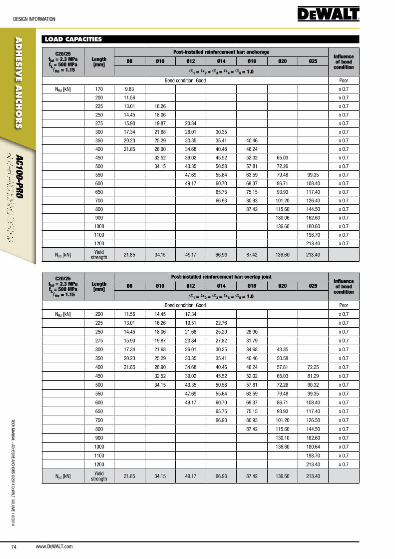
www.DEWALT.com74
TecH ManUal – aDHesIVe ancHoRs ©
2014 DeW
alT VolUMe 1 6/2014
ADHES
IVE A
NCHO
RS
DesIGn InfoRMaTIon
LOAD CAPACITIES
C20/25fbd = 2.3 MPa fy = 500 MPa g
Ms = 1.15
Length [mm]
Post-installed reinforcement bar: anchorageInfluence of bond
conditionØ8 Ø10 Ø12 Ø14 Ø16 Ø20 Ø25
a1 = a2 = a3 = a4 = a5 = 1.0
bond condition: Good Poor
nRd [kn] 170 9.83 x 0.7
200 11.56 x 0.7
225 13.01 16.26 x 0.7
250 14.45 18.06 x 0.7
275 15.90 19.87 23.84 x 0.7
300 17.34 21.68 26.01 30.35 x 0.7
350 20.23 25.29 30.35 35.41 40.46 x 0.7
400 21.85 28.90 34.68 40.46 46.24 x 0.7
450 32.52 39.02 45.52 52.02 65.03 x 0.7
500 34.15 43.35 50.58 57.81 72.26 x 0.7
550 47.69 55.64 63.59 79.48 99.35 x 0.7
600 49.17 60.70 69.37 86.71 108.40 x 0.7
650 65.75 75.15 93.93 117.40 x 0.7
700 66.93 80.93 101.20 126.40 x 0.7
800 87.42 115.60 144.50 x 0.7
900 130.06 162.60 x 0.7
1000 136.60 180.60 x 0.7
1100 198.70 x 0.7
1200 213.40 x 0.7
nyd [kn] yield strength 21.85 34.15 49.17 66.93 87.42 136.60 213.40
C20/25fbd = 2.3 MPa fy = 500 MPa g
Ms = 1.15
Length [mm]
Post-installed reinforcement bar: overlap jointInfluence of bond
conditionØ8 Ø10 Ø12 Ø14 Ø16 Ø20 Ø25
a1 = a2 = a3 = a4 = a5 = 1.0
bond condition: Good Poor
nRd [kn] 200 11.56 14.45 17.34 x 0.7
225 13.01 16.26 19.51 22.76 x 0.7
250 14.45 18.06 21.68 25.29 28.90 x 0.7
275 15.90 19.87 23.84 27.82 31.79 x 0.7
300 17.34 21.68 26.01 30.35 34.68 43.35 x 0.7
350 20.23 25.29 30.35 35.41 40.46 50.58 x 0.7
400 21.85 28.90 34.68 40.46 46.24 57.81 72.25 x 0.7
450 32.52 39.02 45.52 52.02 65.03 81.29 x 0.7
500 34.15 43.35 50.58 57.81 72.26 90.32 x 0.7
550 47.69 55.64 63.59 79.48 99.35 x 0.7
600 49.17 60.70 69.37 86.71 108.40 x 0.7
650 65.75 75.15 93.93 117.40 x 0.7
700 66.93 80.93 101.20 126.50 x 0.7
800 87.42 115.60 144.50 x 0.7
900 130.10 162.60 x 0.7
1000 136.60 180.64 x 0.7
1100 198.70 x 0.7
1200 213.40 x 0.7
nyd [kn] yield strength 21.85 34.15 49.17 66.93 87.42 136.60 213.40
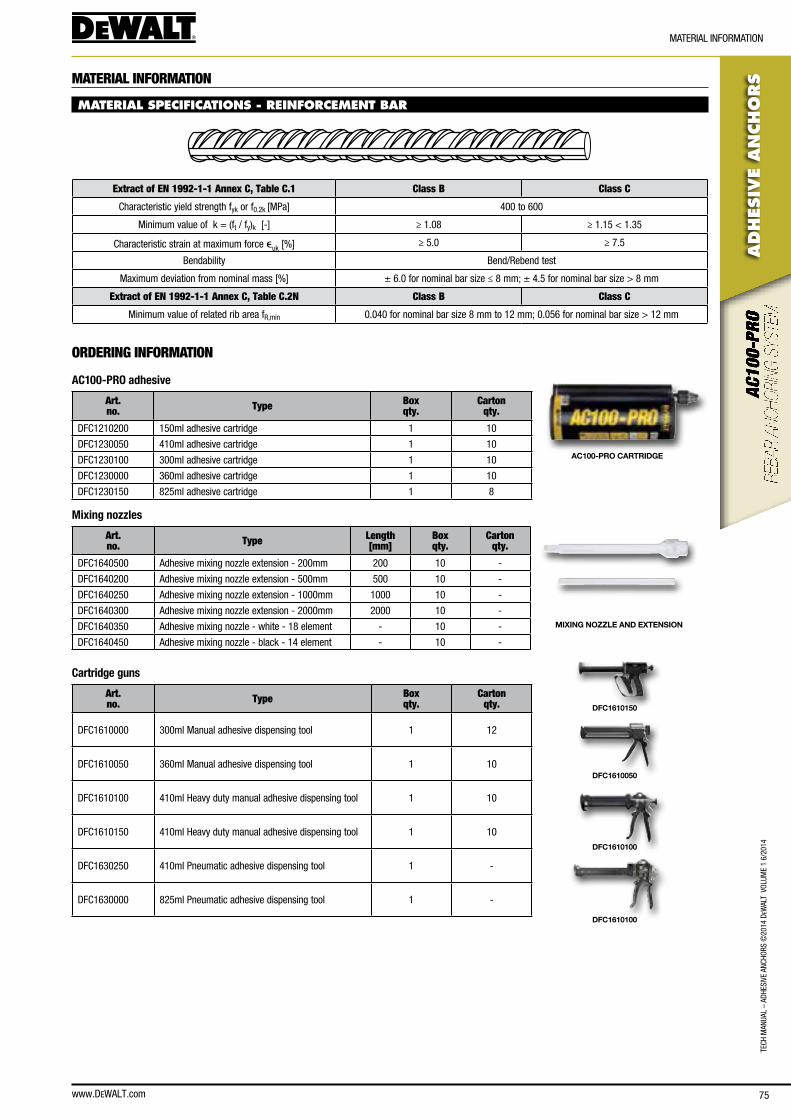
www.DEWALT.com 75
TecH
Man
Ual
– aD
HesI
Ve a
ncHo
Rs ©
2014
DeW
alT
Vol
UMe
1 6/
2014
ADHES
IVE
AN
CHO
RS
MaTeRIal InfoRMaTIon
MATERIAL INFORMATION
MATERIAL SPECIFICATIONS - REINFORCEMENT BAR
Extract of EN 1992-1-1 Annex C, Table C.1 Class B Class C
characteristic yield strength fyk or f0.2k [MPa] 400 to 600
Minimum value of k = (ft / fy)k [-] ≥ 1.08 ≥ 1.15 < 1.35
characteristic strain at maximum force euk [%] ≥ 5.0 ≥ 7.5
bendability bend/Rebend test
Maximum deviation from nominal mass [%] ± 6.0 for nominal bar size ≤ 8 mm; ± 4.5 for nominal bar size > 8 mm
Extract of EN 1992-1-1 Annex C, Table C.2N Class B Class C
Minimum value of related rib area fR,min 0.040 for nominal bar size 8 mm to 12 mm; 0.056 for nominal bar size > 12 mm
ORDERING INFORMATION
AC100-PRO adhesive
Art. no. Type Box
qty.Carton
qty.
Dfc1210200 150ml adhesive cartridge 1 10
Dfc1230050 410ml adhesive cartridge 1 10
Dfc1230100 300ml adhesive cartridge 1 10
Dfc1230000 360ml adhesive cartridge 1 10
Dfc1230150 825ml adhesive cartridge 1 8
AC100-PRO CARTRIDGE
Mixing nozzles
Art. no. Type Length
[mm]Box qty.
Carton qty.
Dfc1640500 adhesive mixing nozzle extension - 200mm 200 10 -
Dfc1640200 adhesive mixing nozzle extension - 500mm 500 10 -
Dfc1640250 adhesive mixing nozzle extension - 1000mm 1000 10 -
Dfc1640300 adhesive mixing nozzle extension - 2000mm 2000 10 -
Dfc1640350 adhesive mixing nozzle - white - 18 element - 10 -
Dfc1640450 adhesive mixing nozzle - black - 14 element - 10 -
MIXING NOZZLE AND EXTENSION
Cartridge guns
Art. no. Type Box
qty.Carton
qty.
Dfc1610000 300ml Manual adhesive dispensing tool 1 12
Dfc1610050 360ml Manual adhesive dispensing tool 1 10
Dfc1610100 410ml Heavy duty manual adhesive dispensing tool 1 10
Dfc1610150 410ml Heavy duty manual adhesive dispensing tool 1 10
Dfc1630250 410ml Pneumatic adhesive dispensing tool 1 -
Dfc1630000 825ml Pneumatic adhesive dispensing tool 1 -
DFC1610150
DFC1610050
DFC1610100
DFC1610100
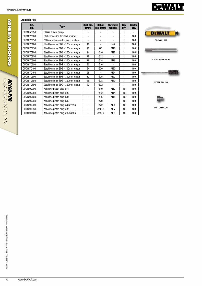
www.DEWALT.com76
TecH ManUal – aDHesIVe ancHoRs ©
2014 DeW
alT VolUMe 1 6/2014
ADHES
IVE A
NCHO
RS
MaTeRIal InfoRMaTIon
Accessories
Art. no. Type Drill dia.
[mm]Rebar
dia. [mm]Threaded rod dia.
Box qty.
Carton qty.
Dfc1650050 DeWalT blow pump - - - 1 -
Dfc1670000 sDs connection for steel brushes - - - 1 100
Dfc1670050 300mm extension for steel brushes - - - 1 100
Dfc1670100 steel brush for sDs - 170mm length 10 - M8 1 100
Dfc1670150 steel brush for sDs - 170mm length 12 Ø8 M10 1 100
Dfc1670200 steel brush for sDs - 200mm length 14 Ø10 M12 1 100
Dfc1670250 steel brush for sDs - 200mm length 16 Ø12 - 1 100
Dfc1670300 steel brush for sDs - 300mm length 18 Ø14 M16 1 100
Dfc1670350 steel brush for sDs - 300mm length 20 Ø16 - 1 100
Dfc1670400 steel brush for sDs - 300mm length 24 Ø20 M20 1 100
Dfc1670450 steel brush for sDs - 300mm length 28 - M24 1 100
Dfc1670500 steel brush for sDs - 300mm length 32 Ø25 M27 1 100
Dfc1670550 steel brush for sDs - 300mm length 35 Ø28 M30 1 100
Dfc1670600 steel brush for sDs - 300mm length 37 Ø32 - 1 100
Dfc1690000 adhesive piston plug #14 - Ø10 M12 10 100
Dfc1690050 adhesive piston plug #16 - Ø12 M14 10 100
Dfc1690150 adhesive piston plug #20 - Ø16 M18 10 100
Dfc1690250 adhesive piston plug #25 - Ø20 - 10 100
Dfc1690300 adhesive piston plug #28(27/29) - Ø22 M24 10 100
Dfc1690350 adhesive piston plug #32 - Ø24-25 M27 10 100
Dfc1690400 adhesive piston plug #35(34/36) - Ø28-32 M30 10 100
BLOW PUMP
SDS CONNECTION
STEEL BRUSH
PISTON PLUG
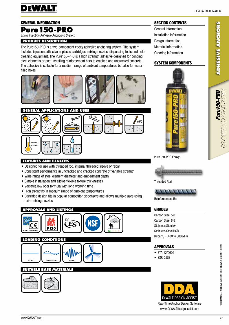
www.DEWALT.com 77
TecH
Man
Ual
– aD
HesI
Ve a
ncHo
Rs ©
2014
DeW
alT
Vol
UMe
1 6/
2014
ADHES
IVE
AN
CHO
RS
GeneRal InfoRMaTIon
SECTION CONTENTSGeneral Information
Installation Information
Design Information
Material Information
ordering Information
SYSTEM COMPONENTS
Pure150-PRo epoxy
Threaded Rod
Reinforcement bar
GRADEScarbon steel 5.8
carbon steel 8.8
stainless steel a4
stainless steel HcR
Rebar fy = 400 to 600 MPa
APPROVALS• eTa-12/0605
• esR-2583
GENERAL INFORMATION
Pure15 0-PROEpoxy Injection Adhesive Anchoring System
PRODUCT DESCRIPTION
The Pure150-PRo is a two-component epoxy adhesive anchoring system. The system includes injection adhesive in plastic cartridges, mixing nozzles, dispensing tools and hole cleaning equipment. The Pure150-PRo is a high strength adhesive designed for bonding steel elements or post-installing reinforcement bars to cracked and uncracked concrete. The adhesive is suitable for a medium range of ambient temperatures but also for water filled holes.
GENERAL APPLICATIONS AND USES
+5˚C
40/24˚C
72/43˚C
FEATURES AND BENEFITS• Designed for use with threaded rod, internal threaded sleeve or rebar• consistent performance in uncracked and cracked concrete of variable strength• Wide range of steel element diameter and embedment depth• simple installation and allows flexible fixture thicknesses• Versatile low odor formula with long working time• High strengths in medium range of ambient temperatures• cartridge design fits in popular competitor dispensers and allows multiple uses using
extra mixing nozzles
APPROVALS AND LISTINGS
ETAG 001 Option 1 F120
A+ A B C
LOADING CONDITIONS
STATIC QUASI-STATIC SEISMIC
SUITABLE BASE MATERIALS
DEWALT DESIGN ASSIST
Real-Time anchor Design software
www.DeWalTdesignassist.com

www.DEWALT.com78
ADHES
IVE A
NCHO
RS
InsTallaTIon InfoRMaTIon
TecH ManUal – aDHesIVe ancHoRs ©
2014 DeW
alT VolUMe 1 6/2014
InsTallaTIon InfoRMaTIon
INSTALLATION INFORMATION
INSTALLATION DATA - THREADED ROD
Notation UnitPure150-PRO - Threaded rod
M8 M10 M12 M16 M20 M24 M27 M30
anchor diameter d [mm] 8 10 12 16 20 24 27 30
nominal drill bit diameter d0 [mm] 10 12 14 18 24 28 32 35
Diameter of hole clearance in fixture df [mm] 9 12 14 18 22 26 30 33
Diameter of steel brush db [mm] 12 14 16 20 26 30 34 37
Minimum embedment and drill hole depth Maximum embedment and drill hole depth
hef,min = h1 hef,max = h1
[mm] [mm]
60 160
60 200
70 240
80 320
90 400
96 480
108 540
120 600
Minimum member thickness hmin [mm] hef + 30 mm ≥ 100 mm hef + 2 · d0
Minimum spacing smin [mm] 40 50 60 80 100 120 135 150
Minimum edge distance cmin [mm] 40 50 60 80 100 120 135 150
Thickness of fixture tfix [mm] 0 mm ≤ tfix ≤ 1500 mm
Maximum torque Tmax [nm] 10 20 40 80 120 160 180 200
Torque wrench socket size sw [mm] 13 17 19 24 30 36 41 46
hmin
h1
hef
d0
Sw
Tmax
df
tfix
INSTALLATION DATA - REINFORCEMENT BAR
Notation UnitPure150-PRO - Reinforcement bar
Ø8 Ø10 Ø12 Ø14 Ø16 Ø20 Ø25 Ø28 Ø32
nominal diameter of rebar d [mm] 8 10 12 14 16 20 25 28 32
nominal drill bit diameter d0 [mm] 12 14 16 18 20 24 32 35 37
Diameter of steel brush db [mm] 14 16 18 20 22 26 34 37 40
Minimum embedment and drill hole depth Maximum embedment and drill hole depth
hef,min = h1 hef,max = h1
[mm] [mm]
60 160
60 200
70 240
75 280
80 320
90 400
100 480
112 540
128 640
Minimum member thickness hmin [mm] hef + 30 mm ≥ 100 mm hef + 2 · d0
Minimum edge distance cmin [mm] 40 50 60 70 80 100 125 140 160
Minimum spacing smin [mm] 40 50 60 70 80 100 125 140 160
hef
d0
h1

www.DEWALT.com 79
TecH
Man
Ual
– aD
HesI
Ve a
ncHo
Rs ©
2014
DeW
alT
Vol
UMe
1 6/
2014
ADHES
IVE
AN
CHO
RS
InsTallaTIon InfoRMaTIon
INSTALLATION INSTRUCTIONS
2X 2X 2X
e.g.
20˚C
10 hr
1.) Using the proper drill bit size, drill a hole into the base material to the required depth.
2.) Blow the hole clean using a hand pump or compressed air 2 times minimum.
3.) Brush the hole with the proper wire brush 2 times minimum.
4.) Blow the hole clean using a hand pump or compressed air 2 times minimum.
5.) After dispensing a minimum of 3 strokes, fill the hole up to approximately 2/3 with adhesive.
6.) Push the steel element into the hole while turning slightly.
7.) Allow the adhesive to cure for the time specified for the actual concrete temperature.
for complete installation instructions, see technical approval.
Concrete temperature Working time Minimum curing time1)
≥ + 5°c 120 min 50 h
≥ + 10°c 90 min 30 h
≥ + 20°c 30 min 10 h
≥ + 30°c 20 min 6 h
≥ + 40°c 12 min 4 h
1) Time data for dry concrete, double curing time for wet concrete
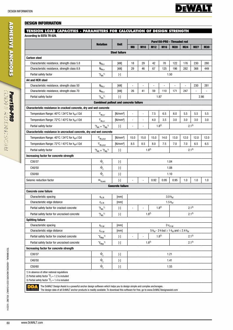
www.DEWALT.com80
TecH ManUal – aDHesIVe ancHoRs ©
2014 DeW
alT VolUMe 1 6/2014
ADHES
IVE A
NCHO
RS
DesIGn InfoRMaTIon
DESIGN INFORMATION
TENSION LOAD CAPACITIES - PARAMETERS FOR CALCULATION OF DESIGN STRENGTHAccording to EOTA TR 029.
Notation UnitPure150-PRO - Threaded rod
M8 M10 M12 M16 M20 M24 M27 M30
Steel failure
Carbon steel
characteristic resistance, strength class 5.8 nRk,s [kn] 18 29 42 78 122 176 230 280
characteristic resistance, strength class 8.8 nRk,s [kn] 29 46 67 125 196 282 368 449
Partial safety factor gMs
1) [-] 1.50
A4 and HCR steel
characteristic resistance, strength class 50 nRk,s [kn] - - - - - - 230 281
characteristic resistance, strength class 70 nRk,s [kn] 26 41 59 110 171 247 - -
Partial safety factor gMs
1) [-] 1.87 2.86
Combined pullout and concrete failure
Characteristic resistance in cracked concrete, dry and wet concrete
Temperature Range: 40°c / 24°c for hef≤12d tRk,cr [n/mm²] - - 7.5 6.5 6.0 5.5 5.5 5.5
Temperature Range: 72°c / 43°c for hef≤12d tRk,cr [n/mm²] - - 4.0 3.5 3.0 3.0 3.0 3.0
Partial safety factor gMc = gMp
1) [-] - - 1.82) 2.13)
Characteristic resistance in uncracked concrete, dry and wet concrete
Temperature Range: 40°c / 24°c for hef≤12d tRk,uncr [n/mm²] 15.0 15.0 15.0 14.0 13.0 12.0 12.0 12.0
Temperature Range: 72°c / 43°c for hef≤12d tRk,uncr [n/mm²] 8.5 8.5 8.0 7.5 7.0 7.0 6.5 6.5
Partial safety factor gMc = gMp
1) [-] 1.82) 2.13)
Increasing factor for concrete strength
c30/37 cc [-] 1.04
c40/50 cc [-] 1.08
c50/60 cc [-] 1.10
seismic reduction factor an,seis [-] - - 0.92 0.95 0.95 1.0 1.0 1.0
Concrete failure
Concrete cone failure
characteristic spacing scr,n [mm] 3.0·hef
characteristic edge distance ccr,n [mm] 1.5·hef
Partial safety factor for cracked concrete gMc
1) [-] - - 1.82) 2.13)
Partial safety factor for uncracked concrete gMc
1) [-] 1.82) 2.13)
Splitting failure
characteristic spacing scr,sp [mm] 2·ccr,sp
characteristic edge distance ccr,sp [mm] 5·hef - 2·h but ≥ 1·hef and ≤ 2.4·hef
Partial safety factor for cracked concrete gMsp
1) [-] - - 1.82) 2.13)
Partial safety factor for uncracked concrete gMsp
1) [-] 1.82) 2.13)
Increasing factor for concrete strength
c30/37 cc [-] 1.21
c40/50 cc [-] 1.41
c50/60 cc [-] 1.55
1) In absence of other national regulations
2) Partial safety factor g2 = 1.2 is included
3) Partial safety factor g2 = 1.4 is included
DEWALT DESIGN ASSIST
The DeWalT Design assist is a powerful anchor design software which helps you to design simple and complex anchorages.The design data of all DeWalT anchor products is readily available. To download this software for free, go to www.DeWalTdesignassist.com
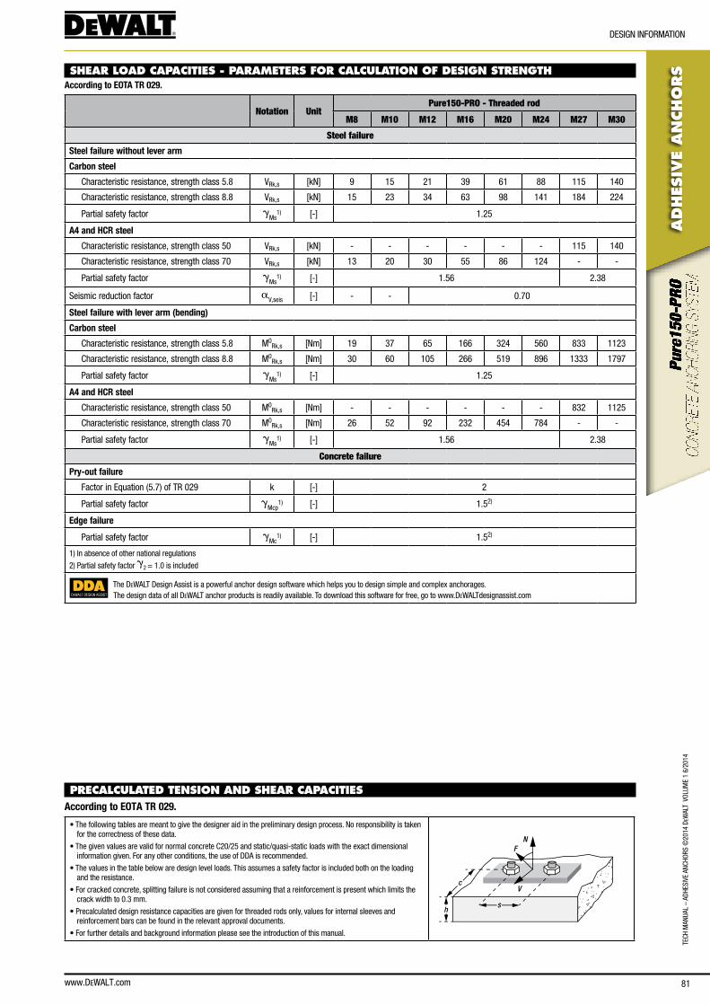
www.DEWALT.com 81
TecH
Man
Ual
– aD
HesI
Ve a
ncHo
Rs ©
2014
DeW
alT
Vol
UMe
1 6/
2014
ADHES
IVE
AN
CHO
RS
DesIGn InfoRMaTIon
SHEAR LOAD CAPACITIES - PARAMETERS FOR CALCULATION OF DESIGN STRENGTHAccording to EOTA TR 029.
Notation UnitPure150-PRO - Threaded rod
M8 M10 M12 M16 M20 M24 M27 M30
Steel failure
Steel failure without lever arm
Carbon steel
characteristic resistance, strength class 5.8 VRk,s [kn] 9 15 21 39 61 88 115 140
characteristic resistance, strength class 8.8 VRk,s [kn] 15 23 34 63 98 141 184 224
Partial safety factor gMs
1) [-] 1.25
A4 and HCR steel
characteristic resistance, strength class 50 VRk,s [kn] - - - - - - 115 140
characteristic resistance, strength class 70 VRk,s [kn] 13 20 30 55 86 124 - -
Partial safety factor gMs
1) [-] 1.56 2.38
seismic reduction factor aV,seis [-] - - 0.70
Steel failure with lever arm (bending)
Carbon steel
characteristic resistance, strength class 5.8 M0Rk,s [nm] 19 37 65 166 324 560 833 1123
characteristic resistance, strength class 8.8 M0Rk,s [nm] 30 60 105 266 519 896 1333 1797
Partial safety factor gMs
1) [-] 1.25
A4 and HCR steel
characteristic resistance, strength class 50 M0Rk,s [nm] - - - - - - 832 1125
characteristic resistance, strength class 70 M0Rk,s [nm] 26 52 92 232 454 784 - -
Partial safety factor gMs
1) [-] 1.56 2.38
Concrete failure
Pry-out failure
factor in equation (5.7) of TR 029 k [-] 2
Partial safety factor gMcp
1) [-] 1.52)
Edge failure
Partial safety factor gMc
1) [-] 1.52)
1) In absence of other national regulations
2) Partial safety factor g2 = 1.0 is included
DEWALT DESIGN ASSIST
The DeWalT Design assist is a powerful anchor design software which helps you to design simple and complex anchorages.The design data of all DeWalT anchor products is readily available. To download this software for free, go to www.DeWalTdesignassist.com
PRECALCULATED TENSION AND SHEAR CAPACITIES According to EOTA TR 029.
• The following tables are meant to give the designer aid in the preliminary design process. no responsibility is taken for the correctness of these data.
• The given values are valid for normal concrete c20/25 and static/quasi-static loads with the exact dimensional information given. for any other conditions, the use of DDa is recommended.
• The values in the table below are design level loads. This assumes a safety factor is included both on the loading and the resistance.
• for cracked concrete, splitting failure is not considered assuming that a reinforcement is present which limits the crack width to 0.3 mm.
• Precalculated design resistance capacities are given for threaded rods only, values for internal sleeves and reinforcement bars can be found in the relevant approval documents.
• for further details and background information please see the introduction of this manual.
N
V
F
sh
c
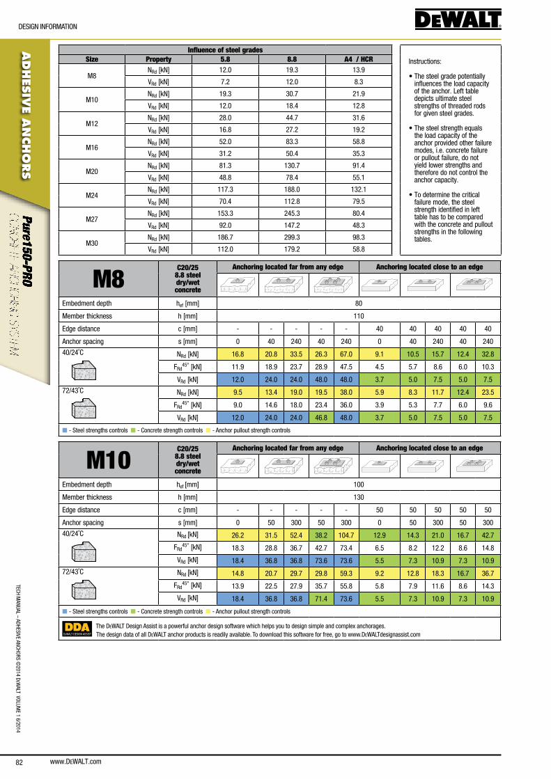
www.DEWALT.com82
TecH ManUal – aDHesIVe ancHoRs ©
2014 DeW
alT VolUMe 1 6/2014
ADHES
IVE A
NCHO
RS
DesIGn InfoRMaTIon
Influence of steel grades
Instructions:
• The steel grade potentially influences the load capacity of the anchor. left table depicts ultimate steel strengths of threaded rods for given steel grades.
• The steel strength equals the load capacity of the anchor provided other failure modes, i.e. concrete failure or pullout failure, do not yield lower strengths and therefore do not control the anchor capacity.
• To determine the critical failure mode, the steel strength identified in left table has to be compared with the concrete and pullout strengths in the following tables.
Size Property 5.8 8.8 A4 / HCR
M8nRd [kn] 12.0 19.3 13.9
VRd [kn] 7.2 12.0 8.3
M10nRd [kn] 19.3 30.7 21.9
VRd [kn] 12.0 18.4 12.8
M12nRd [kn] 28.0 44.7 31.6
VRd [kn] 16.8 27.2 19.2
M16nRd [kn] 52.0 83.3 58.8
VRd [kn] 31.2 50.4 35.3
M20nRd [kn] 81.3 130.7 91.4
VRd [kn] 48.8 78.4 55.1
M24nRd [kn] 117.3 188.0 132.1
VRd [kn] 70.4 112.8 79.5
M27nRd [kn] 153.3 245.3 80.4
VRd [kn] 92.0 147.2 48.3
M30nRd [kn] 186.7 299.3 98.3
VRd [kn] 112.0 179.2 58.8
M8C20/25
8.8 steel dry/wetconcrete
Anchoring located far from any edge Anchoring located close to an edge
embedment depth hef [mm] 80
Member thickness h [mm] 110
edge distance c [mm] - - - - - 40 40 40 40 40
anchor spacing s [mm] 0 40 240 40 240 0 40 240 40 240
40/24˚c nRd [kn] 16.8 20.8 33.5 26.3 67.0 9.1 10.5 15.7 12.4 32.8
fRd45° [kn] 11.9 18.9 23.7 28.9 47.5 4.5 5.7 8.6 6.0 10.3
VRd [kn] 12.0 24.0 24.0 48.0 48.0 3.7 5.0 7.5 5.0 7.5
72/43˚c nRd [kn] 9.5 13.4 19.0 19.5 38.0 5.9 8.3 11.7 12.4 23.5
fRd45° [kn] 9.0 14.6 18.0 23.4 36.0 3.9 5.3 7.7 6.0 9.6
VRd [kn] 12.0 24.0 24.0 46.8 48.0 3.7 5.0 7.5 5.0 7.5
n - steel strengths controls n - concrete strength controls n - anchor pullout strength controls
M10C20/25
8.8 steel dry/wetconcrete
Anchoring located far from any edge Anchoring located close to an edge
embedment depth hef [mm] 100
Member thickness h [mm] 130
edge distance c [mm] - - - - - 50 50 50 50 50
anchor spacing s [mm] 0 50 300 50 300 0 50 300 50 300
40/24˚c nRd [kn] 26.2 31.5 52.4 38.2 104.7 12.9 14.3 21.0 16.7 42.7
fRd45° [kn] 18.3 28.8 36.7 42.7 73.4 6.5 8.2 12.2 8.6 14.8
VRd [kn] 18.4 36.8 36.8 73.6 73.6 5.5 7.3 10.9 7.3 10.9
72/43˚c nRd [kn] 14.8 20.7 29.7 29.8 59.3 9.2 12.8 18.3 16.7 36.7
fRd45° [kn] 13.9 22.5 27.9 35.7 55.8 5.8 7.9 11.6 8.6 14.3
VRd [kn] 18.4 36.8 36.8 71.4 73.6 5.5 7.3 10.9 7.3 10.9
n - steel strengths controls n - concrete strength controls n - anchor pullout strength controls
DEWALT DESIGN ASSIST
The DeWalT Design assist is a powerful anchor design software which helps you to design simple and complex anchorages.The design data of all DeWalT anchor products is readily available. To download this software for free, go to www.DeWalTdesignassist.com
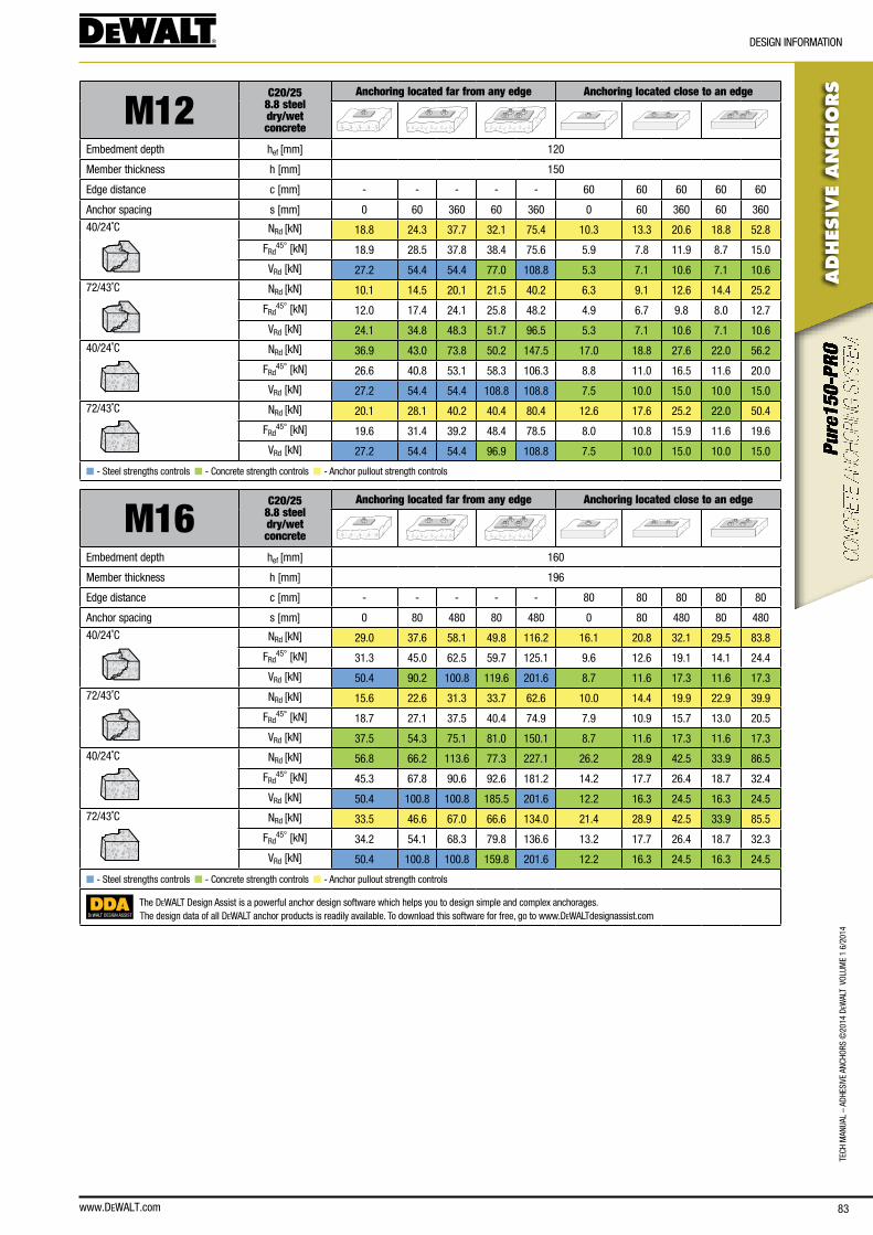
www.DEWALT.com 83
TecH
Man
Ual
– aD
HesI
Ve a
ncHo
Rs ©
2014
DeW
alT
Vol
UMe
1 6/
2014
ADHES
IVE
AN
CHO
RS
DesIGn InfoRMaTIon
M12C20/25
8.8 steel dry/wetconcrete
Anchoring located far from any edge Anchoring located close to an edge
embedment depth hef [mm] 120
Member thickness h [mm] 150
edge distance c [mm] - - - - - 60 60 60 60 60
anchor spacing s [mm] 0 60 360 60 360 0 60 360 60 360
40/24˚c nRd [kn] 18.8 24.3 37.7 32.1 75.4 10.3 13.3 20.6 18.8 52.8
fRd45° [kn] 18.9 28.5 37.8 38.4 75.6 5.9 7.8 11.9 8.7 15.0
VRd [kn] 27.2 54.4 54.4 77.0 108.8 5.3 7.1 10.6 7.1 10.6
72/43˚c nRd [kn] 10.1 14.5 20.1 21.5 40.2 6.3 9.1 12.6 14.4 25.2
fRd45° [kn] 12.0 17.4 24.1 25.8 48.2 4.9 6.7 9.8 8.0 12.7
VRd [kn] 24.1 34.8 48.3 51.7 96.5 5.3 7.1 10.6 7.1 10.6
40/24˚c nRd [kn] 36.9 43.0 73.8 50.2 147.5 17.0 18.8 27.6 22.0 56.2
fRd45° [kn] 26.6 40.8 53.1 58.3 106.3 8.8 11.0 16.5 11.6 20.0
VRd [kn] 27.2 54.4 54.4 108.8 108.8 7.5 10.0 15.0 10.0 15.0
72/43˚c nRd [kn] 20.1 28.1 40.2 40.4 80.4 12.6 17.6 25.2 22.0 50.4
fRd45° [kn] 19.6 31.4 39.2 48.4 78.5 8.0 10.8 15.9 11.6 19.6
VRd [kn] 27.2 54.4 54.4 96.9 108.8 7.5 10.0 15.0 10.0 15.0
n - steel strengths controls n - concrete strength controls n - anchor pullout strength controls
M16C20/25
8.8 steel dry/wetconcrete
Anchoring located far from any edge Anchoring located close to an edge
embedment depth hef [mm] 160
Member thickness h [mm] 196
edge distance c [mm] - - - - - 80 80 80 80 80
anchor spacing s [mm] 0 80 480 80 480 0 80 480 80 480
40/24˚c nRd [kn] 29.0 37.6 58.1 49.8 116.2 16.1 20.8 32.1 29.5 83.8
fRd45° [kn] 31.3 45.0 62.5 59.7 125.1 9.6 12.6 19.1 14.1 24.4
VRd [kn] 50.4 90.2 100.8 119.6 201.6 8.7 11.6 17.3 11.6 17.3
72/43˚c nRd [kn] 15.6 22.6 31.3 33.7 62.6 10.0 14.4 19.9 22.9 39.9
fRd45° [kn] 18.7 27.1 37.5 40.4 74.9 7.9 10.9 15.7 13.0 20.5
VRd [kn] 37.5 54.3 75.1 81.0 150.1 8.7 11.6 17.3 11.6 17.3
40/24˚c nRd [kn] 56.8 66.2 113.6 77.3 227.1 26.2 28.9 42.5 33.9 86.5
fRd45° [kn] 45.3 67.8 90.6 92.6 181.2 14.2 17.7 26.4 18.7 32.4
VRd [kn] 50.4 100.8 100.8 185.5 201.6 12.2 16.3 24.5 16.3 24.5
72/43˚c nRd [kn] 33.5 46.6 67.0 66.6 134.0 21.4 28.9 42.5 33.9 85.5
fRd45° [kn] 34.2 54.1 68.3 79.8 136.6 13.2 17.7 26.4 18.7 32.3
VRd [kn] 50.4 100.8 100.8 159.8 201.6 12.2 16.3 24.5 16.3 24.5
n - steel strengths controls n - concrete strength controls n - anchor pullout strength controls
DEWALT DESIGN ASSIST
The DeWalT Design assist is a powerful anchor design software which helps you to design simple and complex anchorages.The design data of all DeWalT anchor products is readily available. To download this software for free, go to www.DeWalTdesignassist.com

www.DEWALT.com84
TecH ManUal – aDHesIVe ancHoRs ©
2014 DeW
alT VolUMe 1 6/2014
ADHES
IVE A
NCHO
RS
DesIGn InfoRMaTIon
M20C20/25
8.8 steel dry/wetconcrete
Anchoring located far from any edge Anchoring located close to an edge
embedment depth hef [mm] 200
Member thickness h [mm] 248
edge distance c [mm] - - - - - 100 100 100 100 100
anchor spacing s [mm] 0 100 600 100 600 0 100 600 100 600
40/24˚c nRd [kn] 35.9 46.4 71.8 61.3 143.6 20.2 26.0 40.3 36.9 106.9
fRd45° [kn] 41.8 58.0 83.6 76.7 167.2 13.2 17.4 26.5 19.7 34.8
VRd [kn] 78.4 129.9 156.8 171.7 313.6 12.7 16.9 25.4 16.9 25.4
72/43˚c nRd [kn] 18.0 26.2 35.9 39.3 71.8 11.6 17.0 23.3 27.2 46.6
fRd45° [kn] 22.4 32.7 44.9 49.1 89.8 10.3 14.4 20.6 17.7 27.9
VRd [kn] 50.3 73.3 100.5 110.0 201.1 12.7 16.9 25.4 16.9 25.4
40/24˚c nRd [kn] 68.0 79.4 136.0 92.6 272.1 31.3 34.6 50.9 40.6 103.6
fRd45° [kn] 61.8 89.4 123.6 115.8 247.2 19.4 24.0 35.7 25.5 45.2
VRd [kn] 78.4 156.8 156.8 259.2 313.6 17.9 23.9 35.9 23.9 35.9
72/43˚c nRd [kn] 41.9 58.2 83.8 83.1 167.6 27.2 34.6 50.9 40.6 103.6
fRd45° [kn] 46.3 72.1 92.7 103.9 185.3 18.3 24.0 35.7 25.5 45.2
VRd [kn] 78.4 156.8 156.8 232.7 313.6 17.9 23.9 35.9 23.9 35.9
n - steel strengths controls n - concrete strength controls n - anchor pullout strength controls
M24C20/25
8.8 steel dry/wetconcrete
Anchoring located far from any edge Anchoring located close to an edge
embedment depth hef [mm] 240
Member thickness h [mm] 296
edge distance c [mm] - - - - - 120 120 120 120 120
anchor spacing s [mm] 0 120 720 120 720 0 120 720 120 720
40/24˚c nRd [kn] 47.4 61.5 94.8 81.7 189.6 27.1 35.1 54.1 49.7 146.1
fRd45° [kn] 56.6 76.9 113.3 102.1 226.5 18.0 23.7 35.9 26.8 47.6
VRd [kn] 112.8 172.2 225.6 228.6 451.2 17.4 23.2 34.7 23.2 34.7
72/43˚c nRd [kn] 25.9 37.5 51.7 55.9 103.4 16.8 24.3 33.6 38.7 67.1
fRd45° [kn] 32.3 46.8 64.7 69.9 129.3 14.5 20.1 29.0 24.6 38.8
VRd [kn] 72.4 104.9 144.8 156.6 289.5 17.4 23.2 34.7 23.2 34.7
40/24˚c nRd [kn] 89.4 104.3 178.8 121.7 357.6 41.2 45.5 66.9 53.3 136.2
fRd45° [kn] 84.6 121.1 169.3 152.2 338.6 26.1 32.3 48.0 34.4 61.2
VRd [kn] 112.8 225.6 225.6 340.8 451.2 24.5 32.7 49.0 32.7 49.0
72/43˚c nRd [kn] 60.3 82.8 120.6 116.3 241.3 39.1 45.5 66.9 53.3 136.2
fRd45° [kn] 66.7 102.8 133.4 145.5 266.8 25.6 32.3 48.0 34.4 61.2
VRd [kn] 112.8 225.6 225.6 325.7 451.2 24.5 32.7 49.0 32.7 49.0
n - steel strengths controls n - concrete strength controls n - anchor pullout strength controls
DEWALT DESIGN ASSIST
The DeWalT Design assist is a powerful anchor design software which helps you to design simple and complex anchorages.The design data of all DeWalT anchor products is readily available. To download this software for free, go to www.DeWalTdesignassist.com
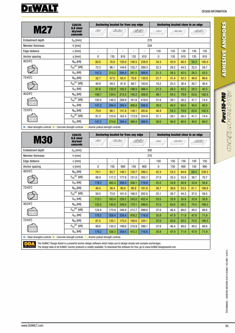
www.DEWALT.com 85
TecH
Man
Ual
– aD
HesI
Ve a
ncHo
Rs ©
2014
DeW
alT
Vol
UMe
1 6/
2014
ADHES
IVE
AN
CHO
RS
DesIGn InfoRMaTIon
M27C20/25
8.8 steel dry/wetconcrete
Anchoring located far from any edge Anchoring located close to an edge
embedment depth hef [mm] 270
Member thickness h [mm] 334
edge distance c [mm] - - - - - 135 135 135 135 135
anchor spacing s [mm] 0 135 810 135 810 0 135 810 135 810
40/24˚c nRd [kn] 60.0 76.9 120.0 100.5 239.9 34.3 43.9 68.5 59.3 185.0
fRd45° [kn] 72.3 96.1 144.6 125.7 289.3 22.3 29.2 44.5 32.5 58.7
VRd [kn] 147.2 215.2 294.4 281.5 588.8 21.3 28.3 42.5 28.3 42.5
72/43˚c nRd [kn] 32.7 47.5 65.4 70.9 130.9 21.7 31.4 43.3 49.9 86.6
fRd45° [kn] 40.9 59.3 81.8 88.7 163.6 18.2 25.3 36.4 30.7 48.4
VRd [kn] 91.6 132.9 183.2 198.5 366.4 21.3 28.3 42.5 28.3 42.5
40/24˚c nRd [kn] 106.7 124.5 213.4 145.2 426.8 49.1 54.3 79.9 63.6 162.5
fRd45° [kn] 105.0 148.5 209.9 181.6 419.9 31.6 39.1 58.2 41.7 74.4
VRd [kn] 147.2 294.4 294.4 406.6 588.8 30.0 40.0 60.0 40.0 60.0
72/43˚c nRd [kn] 70.9 98.1 141.8 139.1 283.6 46.9 54.3 79.9 63.6 162.5
fRd45° [kn] 81.2 122.6 162.4 173.9 324.8 31.1 39.1 58.2 41.7 74.4
VRd [kn] 147.2 274.6 294.4 389.4 588.8 30.0 40.0 60.0 40.0 60.0
n - steel strengths controls n - concrete strength controls n - anchor pullout strength controls
M30C20/25
8.8 steel dry/wetconcrete
Anchoring located far from any edge Anchoring located close to an edge
embedment depth hef [mm] 300
Member thickness h [mm] 370
edge distance c [mm] - - - - - 150 150 150 150 150
anchor spacing s [mm] 0 150 900 150 900 0 150 900 150 900
40/24˚c nRd [kn] 74.1 93.7 148.1 120.7 296.2 42.3 53.5 84.6 69.4 228.3
fRd45° [kn] 88.9 117.2 177.8 151.0 355.7 27.0 35.3 53.9 38.7 70.7
VRd [kn] 179.2 262.4 358.4 338.1 716.8 25.5 33.9 50.9 33.9 50.9
72/43˚c nRd [kn] 40.4 58.4 80.8 86.8 161.6 26.7 38.6 53.5 61.1 106.9
fRd45° [kn] 50.5 73.0 101.0 108.5 202.0 22.1 30.7 44.3 37.0 58.5
VRd [kn] 113.1 163.4 226.2 243.0 452.4 25.5 33.9 50.9 33.9 50.9
40/24˚c nRd [kn] 125.0 145.8 249.9 170.1 499.8 57.6 63.6 93.5 74.5 190.3
fRd45° [kn] 124.9 175.9 249.9 212.7 499.8 37.6 46.4 69.0 49.5 88.6
VRd [kn] 179.2 358.4 358.4 476.2 716.8 35.9 47.9 71.9 47.9 71.9
72/43˚c nRd [kn] 87.5 120.1 175.0 168.6 350.1 57.6 63.6 93.5 74.5 190.3
fRd45° [kn] 99.8 150.2 199.6 210.9 399.1 37.6 46.4 69.0 49.5 88.6
VRd [kn] 179.2 336.3 358.4 472.2 716.8 35.9 47.9 71.9 47.9 71.9
n - steel strengths controls n - concrete strength controls n - anchor pullout strength controls
DEWALT DESIGN ASSIST
The DeWalT Design assist is a powerful anchor design software which helps you to design simple and complex anchorages.The design data of all DeWalT anchor products is readily available. To download this software for free, go to www.DeWalTdesignassist.com
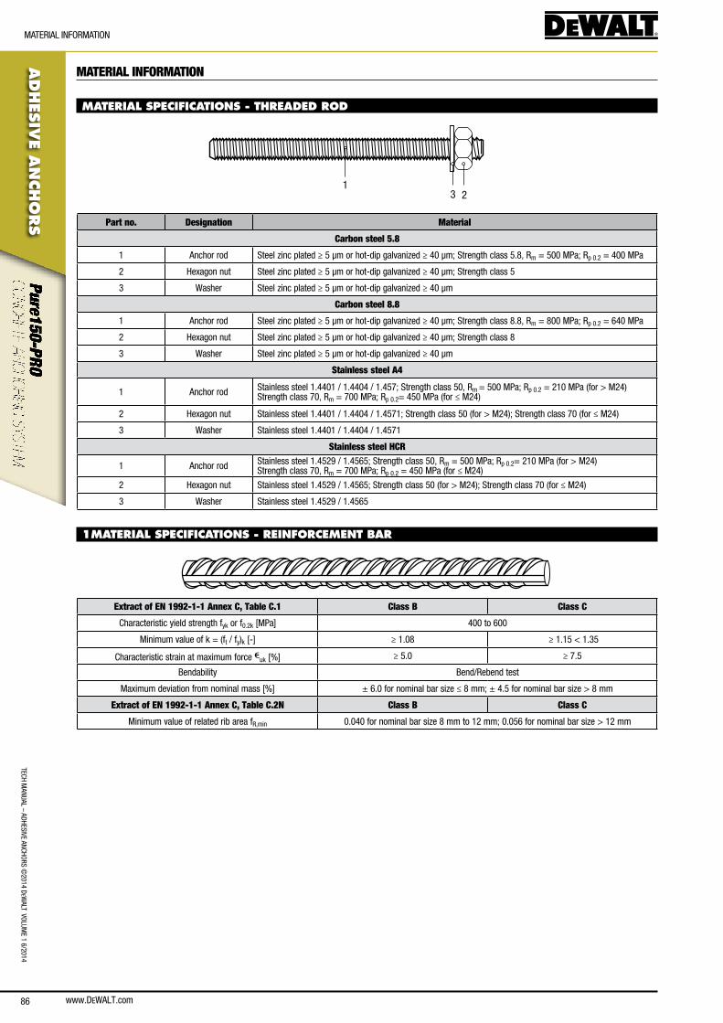
www.DEWALT.com86
TecH ManUal – aDHesIVe ancHoRs ©
2014 DeW
alT VolUMe 1 6/2014
ADHES
IVE A
NCHO
RS
MaTeRIal InfoRMaTIon
MATERIAL INFORMATION
MATERIAL SPECIFICATIONS - THREADED ROD
231
Part no. Designation Material
Carbon steel 5.8
1 anchor rod steel zinc plated ≥ 5 μm or hot-dip galvanized ≥ 40 μm; strength class 5.8, Rm = 500 MPa; Rp 0.2 = 400 MPa
2 Hexagon nut steel zinc plated ≥ 5 μm or hot-dip galvanized ≥ 40 μm; strength class 5
3 Washer steel zinc plated ≥ 5 μm or hot-dip galvanized ≥ 40 μm
Carbon steel 8.8
1 anchor rod steel zinc plated ≥ 5 μm or hot-dip galvanized ≥ 40 μm; strength class 8.8, Rm = 800 MPa; Rp 0.2 = 640 MPa
2 Hexagon nut steel zinc plated ≥ 5 μm or hot-dip galvanized ≥ 40 μm; strength class 8
3 Washer steel zinc plated ≥ 5 μm or hot-dip galvanized ≥ 40 μm
Stainless steel A4
1 anchor rod stainless steel 1.4401 / 1.4404 / 1.457; strength class 50, Rm = 500 MPa; Rp 0.2 = 210 MPa (for > M24)strength class 70, Rm = 700 MPa; Rp 0.2= 450 MPa (for ≤ M24)
2 Hexagon nut stainless steel 1.4401 / 1.4404 / 1.4571; strength class 50 (for > M24); strength class 70 (for ≤ M24)
3 Washer stainless steel 1.4401 / 1.4404 / 1.4571
Stainless steel HCR
1 anchor rod stainless steel 1.4529 / 1.4565; strength class 50, Rm = 500 MPa; Rp 0.2= 210 MPa (for > M24)strength class 70, Rm = 700 MPa; Rp 0.2 = 450 MPa (for ≤ M24)
2 Hexagon nut stainless steel 1.4529 / 1.4565; strength class 50 (for > M24); strength class 70 (for ≤ M24)
3 Washer stainless steel 1.4529 / 1.4565
1MATERIAL SPECIFICATIONS - REINFORCEMENT BAR
Extract of EN 1992-1-1 Annex C, Table C.1 Class B Class C
characteristic yield strength fyk or f0.2k [MPa] 400 to 600
Minimum value of k = (ft / fy)k [-] ≥ 1.08 ≥ 1.15 < 1.35
characteristic strain at maximum force euk [%] ≥ 5.0 ≥ 7.5
bendability bend/Rebend test
Maximum deviation from nominal mass [%] ± 6.0 for nominal bar size ≤ 8 mm; ± 4.5 for nominal bar size > 8 mm
Extract of EN 1992-1-1 Annex C, Table C.2N Class B Class C
Minimum value of related rib area fR,min 0.040 for nominal bar size 8 mm to 12 mm; 0.056 for nominal bar size > 12 mm
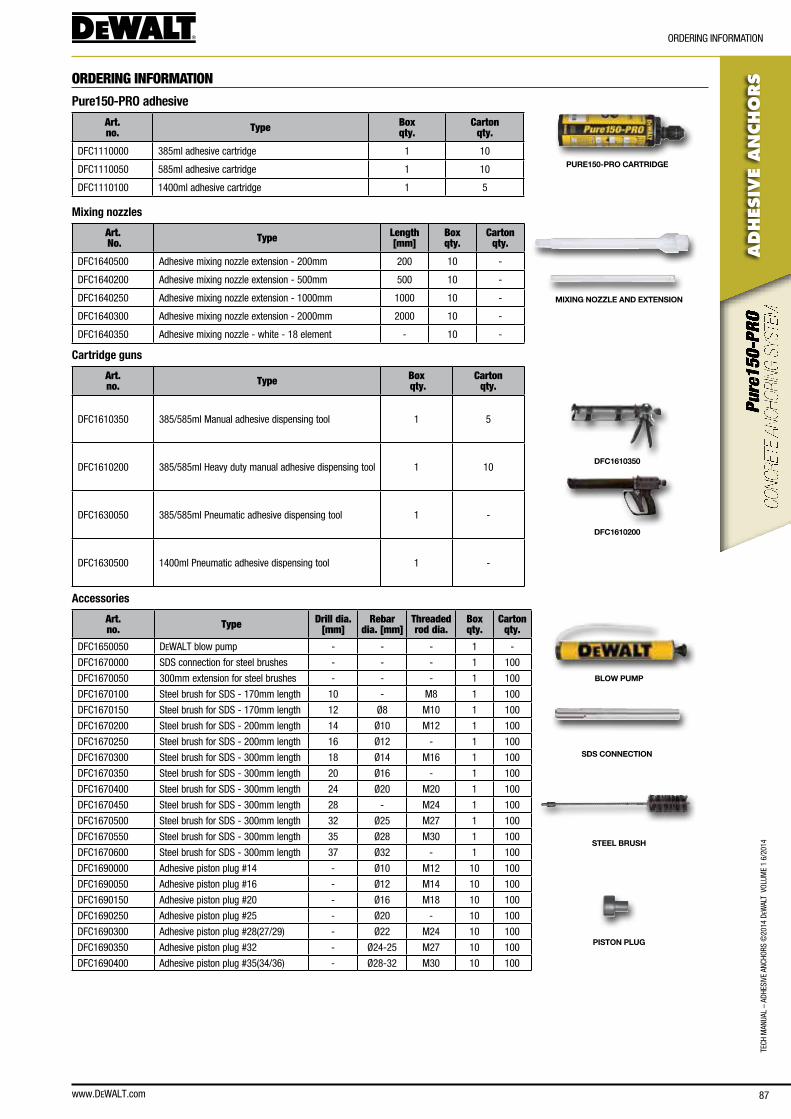
www.DEWALT.com 87
TecH
Man
Ual
– aD
HesI
Ve a
ncHo
Rs ©
2014
DeW
alT
Vol
UMe
1 6/
2014
ADHES
IVE
AN
CHO
RS
oRDeRInG InfoRMaTIon
ORDERING INFORMATION
Pure150-PRO adhesive
Art. no. Type Box
qty.Carton
qty.
Dfc1110000 385ml adhesive cartridge 1 10
Dfc1110050 585ml adhesive cartridge 1 10
Dfc1110100 1400ml adhesive cartridge 1 5
PURE150-PRO CARTRIDGE
Mixing nozzles
Art. No. Type Length
[mm]Box qty.
Carton qty.
Dfc1640500 adhesive mixing nozzle extension - 200mm 200 10 -
Dfc1640200 adhesive mixing nozzle extension - 500mm 500 10 -
Dfc1640250 adhesive mixing nozzle extension - 1000mm 1000 10 -
Dfc1640300 adhesive mixing nozzle extension - 2000mm 2000 10 -
Dfc1640350 adhesive mixing nozzle - white - 18 element - 10 -
MIXING NOZZLE AND EXTENSION
Cartridge guns
Art. no. Type Box
qty.Carton
qty.
Dfc1610350 385/585ml Manual adhesive dispensing tool 1 5
Dfc1610200 385/585ml Heavy duty manual adhesive dispensing tool 1 10
Dfc1630050 385/585ml Pneumatic adhesive dispensing tool 1 -
Dfc1630500 1400ml Pneumatic adhesive dispensing tool 1 -
DFC1610350
DFC1610200
Accessories
Art. no. Type Drill dia.
[mm]Rebar
dia. [mm]Threaded rod dia.
Box qty.
Carton qty.
Dfc1650050 DeWalT blow pump - - - 1 -
Dfc1670000 sDs connection for steel brushes - - - 1 100
Dfc1670050 300mm extension for steel brushes - - - 1 100
Dfc1670100 steel brush for sDs - 170mm length 10 - M8 1 100
Dfc1670150 steel brush for sDs - 170mm length 12 Ø8 M10 1 100
Dfc1670200 steel brush for sDs - 200mm length 14 Ø10 M12 1 100
Dfc1670250 steel brush for sDs - 200mm length 16 Ø12 - 1 100
Dfc1670300 steel brush for sDs - 300mm length 18 Ø14 M16 1 100
Dfc1670350 steel brush for sDs - 300mm length 20 Ø16 - 1 100
Dfc1670400 steel brush for sDs - 300mm length 24 Ø20 M20 1 100
Dfc1670450 steel brush for sDs - 300mm length 28 - M24 1 100
Dfc1670500 steel brush for sDs - 300mm length 32 Ø25 M27 1 100
Dfc1670550 steel brush for sDs - 300mm length 35 Ø28 M30 1 100
Dfc1670600 steel brush for sDs - 300mm length 37 Ø32 - 1 100
Dfc1690000 adhesive piston plug #14 - Ø10 M12 10 100
Dfc1690050 adhesive piston plug #16 - Ø12 M14 10 100
Dfc1690150 adhesive piston plug #20 - Ø16 M18 10 100
Dfc1690250 adhesive piston plug #25 - Ø20 - 10 100
Dfc1690300 adhesive piston plug #28(27/29) - Ø22 M24 10 100
Dfc1690350 adhesive piston plug #32 - Ø24-25 M27 10 100
Dfc1690400 adhesive piston plug #35(34/36) - Ø28-32 M30 10 100
BLOW PUMP
SDS CONNECTION
STEEL BRUSH
PISTON PLUG
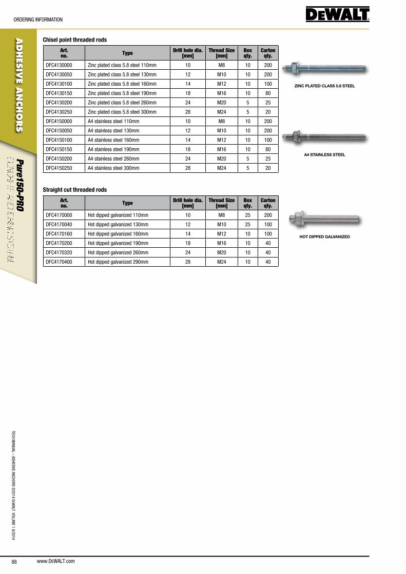
www.DEWALT.com88
TecH ManUal – aDHesIVe ancHoRs ©
2014 DeW
alT VolUMe 1 6/2014
ADHES
IVE A
NCHO
RS
oRDeRInG InfoRMaTIon
Chisel point threaded rods
Art. no. Type Drill hole dia.
[mm]Thread Size
[mm]Box qty.
Carton qty.
Dfc4130000 Zinc plated class 5.8 steel 110mm 10 M8 10 200
Dfc4130050 Zinc plated class 5.8 steel 130mm 12 M10 10 200
Dfc4130100 Zinc plated class 5.8 steel 160mm 14 M12 10 100
Dfc4130150 Zinc plated class 5.8 steel 190mm 18 M16 10 80
Dfc4130200 Zinc plated class 5.8 steel 260mm 24 M20 5 25
Dfc4130250 Zinc plated class 5.8 steel 300mm 28 M24 5 20
Dfc4150000 a4 stainless steel 110mm 10 M8 10 200
Dfc4150050 a4 stainless steel 130mm 12 M10 10 200
Dfc4150100 a4 stainless steel 160mm 14 M12 10 100
Dfc4150150 a4 stainless steel 190mm 18 M16 10 80
Dfc4150200 a4 stainless steel 260mm 24 M20 5 25
Dfc4150250 a4 stainless steel 300mm 28 M24 5 20
Straight cut threaded rods
Art. no. Type Drill hole dia.
[mm]Thread Size
[mm]Box qty.
Carton qty.
Dfc4170000 Hot dipped galvanized 110mm 10 M8 25 200
Dfc4170040 Hot dipped galvanized 130mm 12 M10 25 100
Dfc4170160 Hot dipped galvanized 160mm 14 M12 10 100
Dfc4170200 Hot dipped galvanized 190mm 18 M16 10 40
Dfc4170320 Hot dipped galvanized 260mm 24 M20 10 40
Dfc4170400 Hot dipped galvanized 290mm 28 M24 10 40
ZINC PLATED CLASS 5.8 STEEL
A4 STAINLESS STEEL
HOT DIPPED GALVANIZED
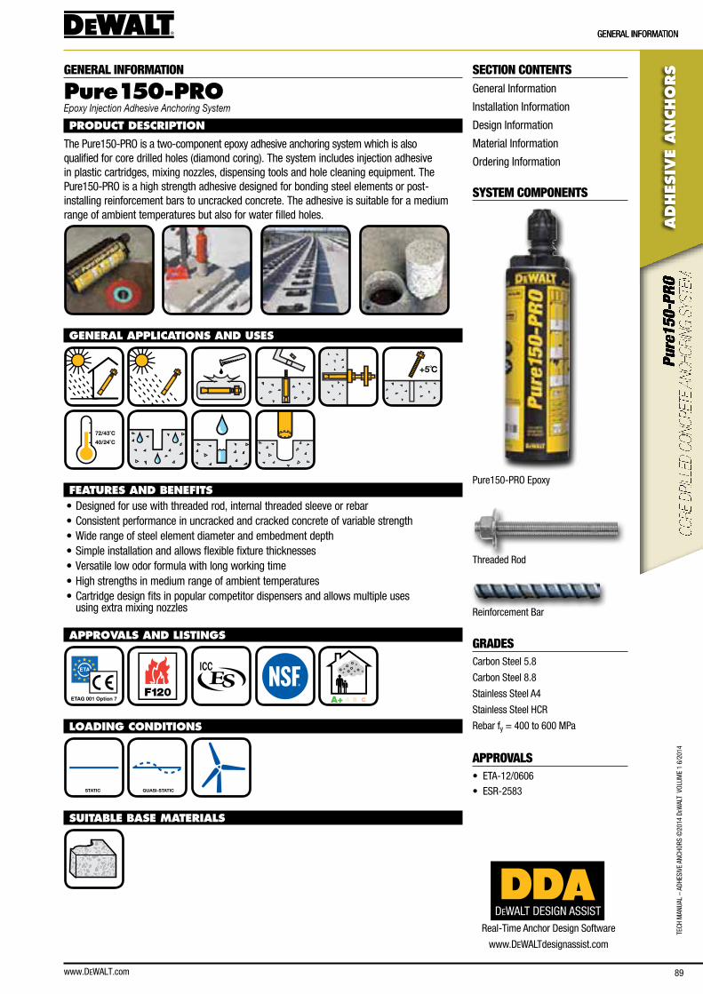
www.DEWALT.com 89
ADHES
IVE
AN
CHO
RS
GeneRal InfoRMaTIon
TecH
Man
Ual
– aD
HesI
Ve a
ncHo
Rs ©
2014
DeW
alT
Vol
UMe
1 6/
2014
GeneRal InfoRMaTIon
SECTION CONTENTSGeneral Information
Installation Information
Design Information
Material Information
ordering Information
SYSTEM COMPONENTS
Pure150-PRo epoxy
Threaded Rod
Reinforcement bar
GRADEScarbon steel 5.8
carbon steel 8.8
stainless steel a4
stainless steel HcR
Rebar fy = 400 to 600 MPa
APPROVALS• eTa-12/0606
• esR-2583
GENERAL INFORMATION
Pure15 0-PROEpoxy Injection Adhesive Anchoring System
PRODUCT DESCRIPTION
The Pure150-PRo is a two-component epoxy adhesive anchoring system which is also qualified for core drilled holes (diamond coring). The system includes injection adhesive in plastic cartridges, mixing nozzles, dispensing tools and hole cleaning equipment. The Pure150-PRo is a high strength adhesive designed for bonding steel elements or post-installing reinforcement bars to uncracked concrete. The adhesive is suitable for a medium range of ambient temperatures but also for water filled holes.
GENERAL APPLICATIONS AND USES
+5˚C
40/24˚C
72/43˚C
FEATURES AND BENEFITS• Designed for use with threaded rod, internal threaded sleeve or rebar• consistent performance in uncracked and cracked concrete of variable strength• Wide range of steel element diameter and embedment depth• simple installation and allows flexible fixture thicknesses• Versatile low odor formula with long working time• High strengths in medium range of ambient temperatures• cartridge design fits in popular competitor dispensers and allows multiple uses
using extra mixing nozzles
APPROVALS AND LISTINGS
ETAG 001 Option 7 F120
A+ A B C
LOADING CONDITIONS
STATIC QUASI-STATIC
SUITABLE BASE MATERIALS
DEWALT DESIGN ASSISTReal-Time anchor Design software
www.DeWalTdesignassist.com
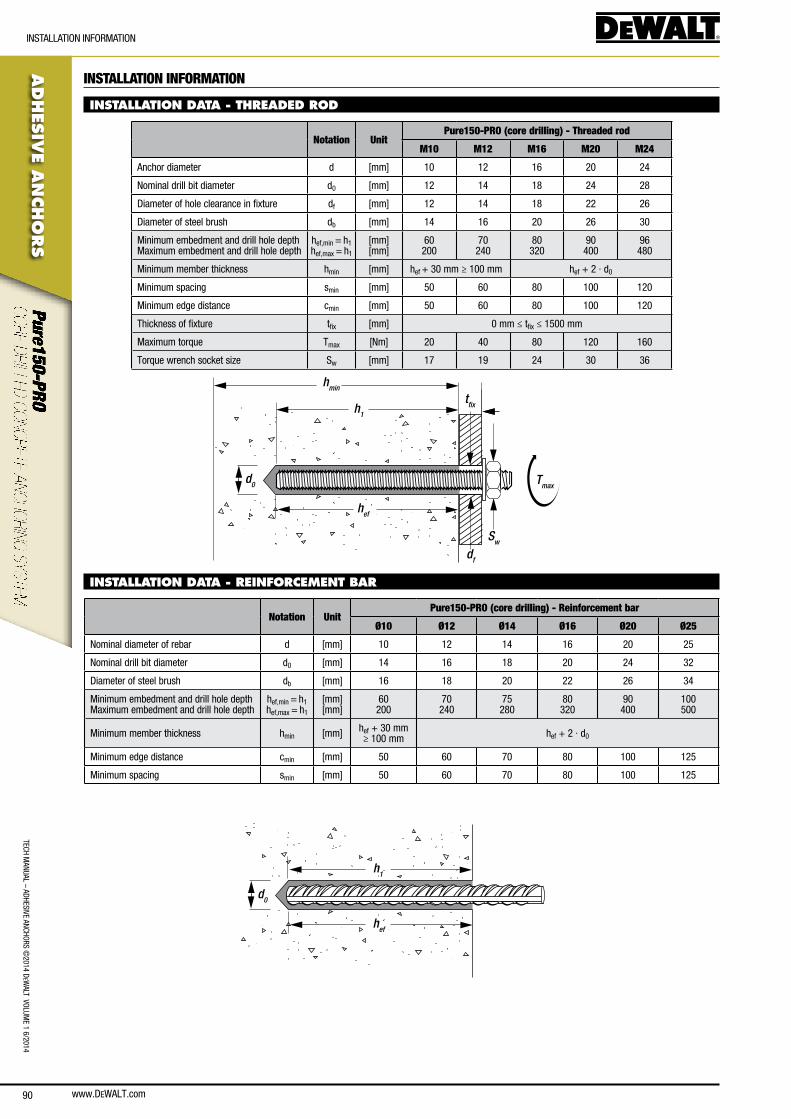
www.DEWALT.com90
TecH ManUal – aDHesIVe ancHoRs ©
2014 DeW
alT VolUMe 1 6/2014
ADHES
IVE A
NCHO
RS
InsTallaTIon InfoRMaTIon
INSTALLATION INFORMATION
INSTALLATION DATA - THREADED ROD
Notation UnitPure150-PRO (core drilling) - Threaded rod
M10 M12 M16 M20 M24
anchor diameter d [mm] 10 12 16 20 24
nominal drill bit diameter d0 [mm] 12 14 18 24 28
Diameter of hole clearance in fixture df [mm] 12 14 18 22 26
Diameter of steel brush db [mm] 14 16 20 26 30
Minimum embedment and drill hole depth Maximum embedment and drill hole depth
hef,min = h1 hef,max = h1
[mm] [mm]
60 200
70 240
80 320
90 400
96 480
Minimum member thickness hmin [mm] hef + 30 mm ≥ 100 mm hef + 2 · d0
Minimum spacing smin [mm] 50 60 80 100 120
Minimum edge distance cmin [mm] 50 60 80 100 120
Thickness of fixture tfix [mm] 0 mm ≤ tfix ≤ 1500 mm
Maximum torque Tmax [nm] 20 40 80 120 160
Torque wrench socket size sw [mm] 17 19 24 30 36
hmin
h1
hef
d0
Sw
Tmax
df
tfix
INSTALLATION DATA - REINFORCEMENT BAR
Notation UnitPure150-PRO (core drilling) - Reinforcement bar
Ø10 Ø12 Ø14 Ø16 Ø20 Ø25
nominal diameter of rebar d [mm] 10 12 14 16 20 25
nominal drill bit diameter d0 [mm] 14 16 18 20 24 32
Diameter of steel brush db [mm] 16 18 20 22 26 34
Minimum embedment and drill hole depth Maximum embedment and drill hole depth
hef,min = h1 hef,max = h1
[mm] [mm]
60 200
70 240
75 280
80 320
90 400
100 500
Minimum member thickness hmin [mm] hef + 30 mm ≥ 100 mm hef + 2 · d0
Minimum edge distance cmin [mm] 50 60 70 80 100 125
Minimum spacing smin [mm] 50 60 70 80 100 125
hef
d0
h1
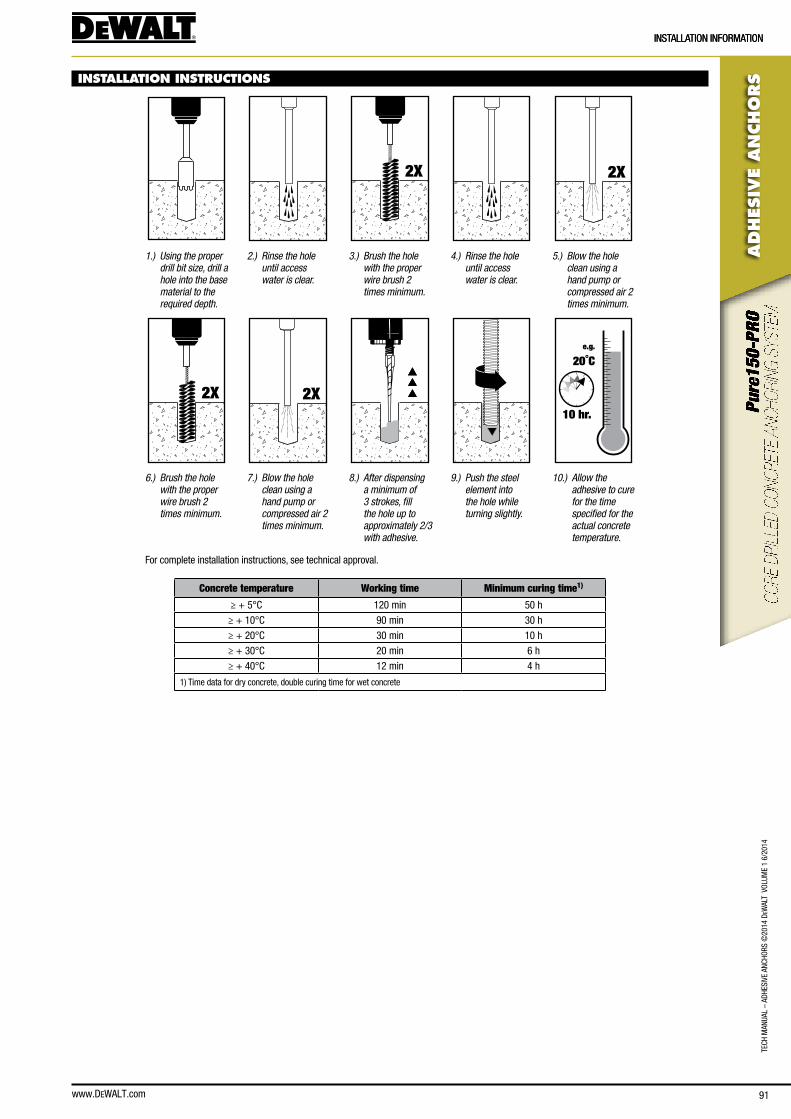
www.DEWALT.com 91
ADHES
IVE
AN
CHO
RS
InsTallaTIon InfoRMaTIon
TecH
Man
Ual
– aD
HesI
Ve a
ncHo
Rs ©
2014
DeW
alT
Vol
UMe
1 6/
2014
InsTallaTIon InfoRMaTIon
INSTALLATION INSTRUCTIONS
2X 2X
1.) Using the proper drill bit size, drill a hole into the base material to the required depth.
2.) Rinse the hole until access water is clear.
3.) Brush the hole with the proper wire brush 2 times minimum.
4.) Rinse the hole until access water is clear.
5.) Blow the hole clean using a hand pump or compressed air 2 times minimum.
2X 2X
e.g.
20˚C
10 hr.
6.) Brush the hole with the proper wire brush 2 times minimum.
7.) Blow the hole clean using a hand pump or compressed air 2 times minimum.
8.) After dispensing a minimum of 3 strokes, fill the hole up to approximately 2/3 with adhesive.
9.) Push the steel element into the hole while turning slightly.
10.) Allow the adhesive to cure for the time specified for the actual concrete temperature.
for complete installation instructions, see technical approval.
Concrete temperature Working time Minimum curing time1)
≥ + 5°c 120 min 50 h
≥ + 10°c 90 min 30 h
≥ + 20°c 30 min 10 h
≥ + 30°c 20 min 6 h
≥ + 40°c 12 min 4 h
1) Time data for dry concrete, double curing time for wet concrete
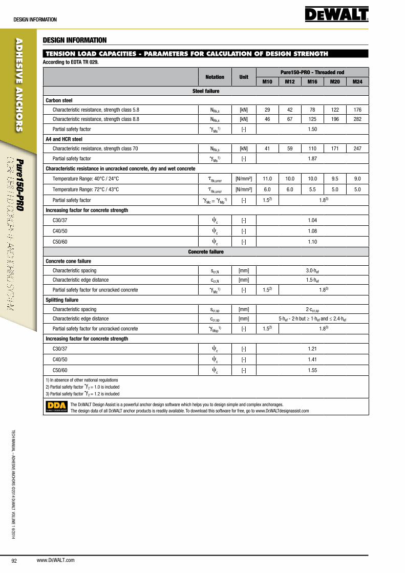
www.DEWALT.com92
TecH ManUal – aDHesIVe ancHoRs ©
2014 DeW
alT VolUMe 1 6/2014
ADHES
IVE A
NCHO
RS
DesIGn InfoRMaTIonDesIGn InfoRMaTIon
DESIGN INFORMATION
TENSION LOAD CAPACITIES - PARAMETERS FOR CALCULATION OF DESIGN STRENGTHAccording to EOTA TR 029.
Notation UnitPure150-PRO - Threaded rod
M10 M12 M16 M20 M24
Steel failure
Carbon steel
characteristic resistance, strength class 5.8 nRk,s [kn] 29 42 78 122 176
characteristic resistance, strength class 8.8 nRk,s [kn] 46 67 125 196 282
Partial safety factor gMs
1) [-] 1.50
A4 and HCR steel
characteristic resistance, strength class 70 nRk,s [kn] 41 59 110 171 247
Partial safety factor gMs
1) [-] 1.87
Characteristic resistance in uncracked concrete, dry and wet concrete
Temperature Range: 40°c / 24°c tRk,uncr [n/mm²] 11.0 10.0 10.0 9.5 9.0
Temperature Range: 72°c / 43°c tRk,uncr [n/mm²] 6.0 6.0 5.5 5.0 5.0
Partial safety factor gMc = gMp
1) [-] 1.52) 1.83)
Increasing factor for concrete strength
c30/37 cc [-] 1.04
c40/50 cc [-] 1.08
c50/60 cc [-] 1.10
Concrete failure
Concrete cone failure
characteristic spacing scr,n [mm] 3.0·hef
characteristic edge distance ccr,n [mm] 1.5·hef
Partial safety factor for uncracked concrete gMc
1) [-] 1.52) 1.83)
Splitting failure
characteristic spacing scr,sp [mm] 2·ccr,sp
characteristic edge distance ccr,sp [mm] 5·hef - 2·h but ≥ 1·hef and ≤ 2.4·hef
Partial safety factor for uncracked concrete gMsp
1) [-] 1.52) 1.83)
Increasing factor for concrete strength
c30/37 cc [-] 1.21
c40/50 cc [-] 1.41
c50/60 cc [-] 1.55
1) In absence of other national regulations
2) Partial safety factor g2 = 1.0 is included
3) Partial safety factor g2 = 1.2 is included
DEWALT DESIGN ASSIST
The DeWalT Design assist is a powerful anchor design software which helps you to design simple and complex anchorages.The design data of all DeWalT anchor products is readily available. To download this software for free, go to www.DeWalTdesignassist.com
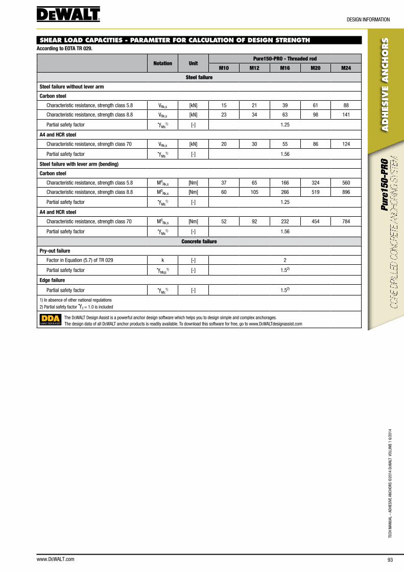
www.DEWALT.com 93
TecH
Man
Ual
– aD
HesI
Ve a
ncHo
Rs ©
2014
DeW
alT
Vol
UMe
1 6/
2014
ADHES
IVE
AN
CHO
RS
DesIGn InfoRMaTIon
SHEAR LOAD CAPACITIES - PARAMETER FOR CALCULATION OF DESIGN STRENGTHAccording to EOTA TR 029.
Notation UnitPure150-PRO - Threaded rod
M10 M12 M16 M20 M24
Steel failure
Steel failure without lever arm
Carbon steel
characteristic resistance, strength class 5.8 VRk,s [kn] 15 21 39 61 88
characteristic resistance, strength class 8.8 VRk,s [kn] 23 34 63 98 141
Partial safety factor gMs
1) [-] 1.25
A4 and HCR steel
characteristic resistance, strength class 70 VRk,s [kn] 20 30 55 86 124
Partial safety factor gMs
1) [-] 1.56
Steel failure with lever arm (bending)
Carbon steel
characteristic resistance, strength class 5.8 M0Rk,s [nm] 37 65 166 324 560
characteristic resistance, strength class 8.8 M0Rk,s [nm] 60 105 266 519 896
Partial safety factor gMs
1) [-] 1.25
A4 and HCR steel
characteristic resistance, strength class 70 M0Rk,s [nm] 52 92 232 454 784
Partial safety factor gMs
1) [-] 1.56
Concrete failure
Pry-out failure
factor in equation (5.7) of TR 029 k [-] 2
Partial safety factor gMcp
1) [-] 1.52)
Edge failure
Partial safety factor gMc
1) [-] 1.52)
1) In absence of other national regulations
2) Partial safety factor g2 = 1.0 is included
DEWALT DESIGN ASSIST
The DeWalT Design assist is a powerful anchor design software which helps you to design simple and complex anchorages.The design data of all DeWalT anchor products is readily available. To download this software for free, go to www.DeWalTdesignassist.com
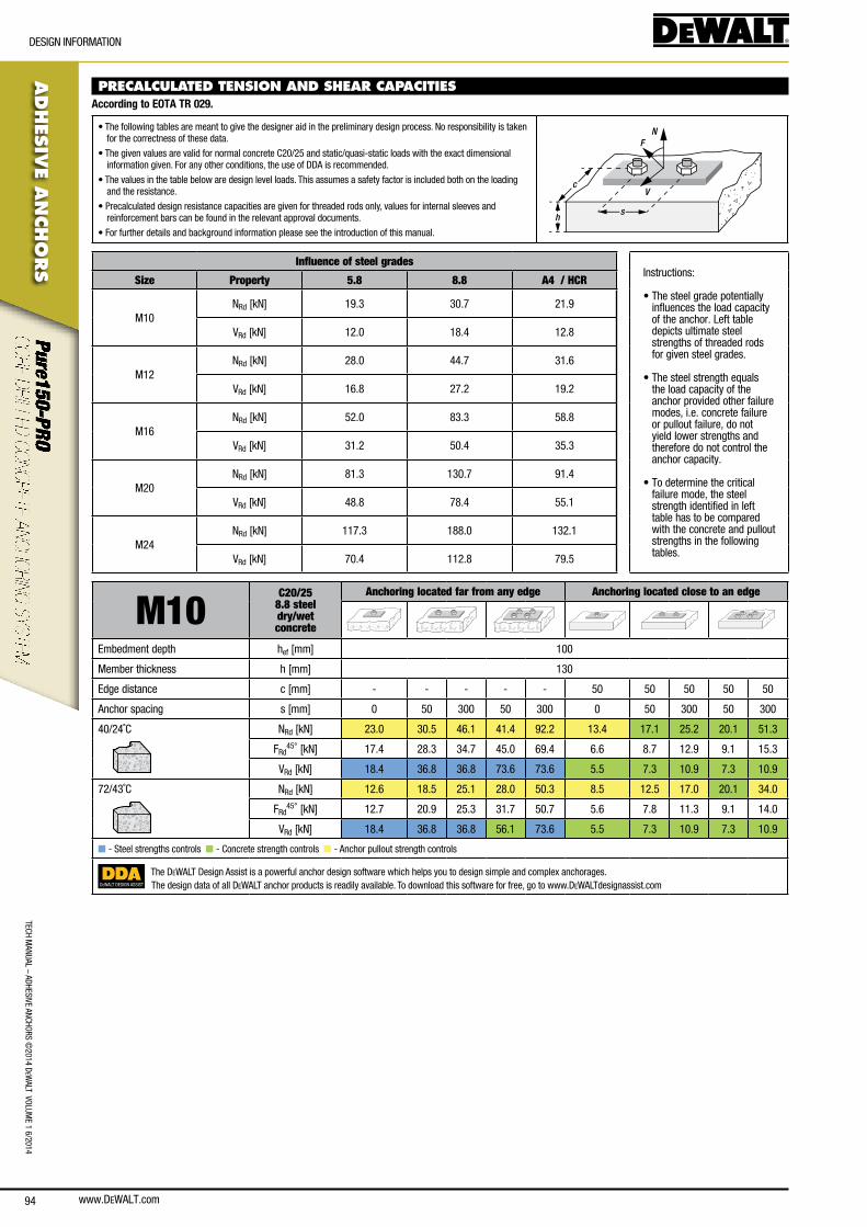
www.DEWALT.com94
TecH ManUal – aDHesIVe ancHoRs ©
2014 DeW
alT VolUMe 1 6/2014
ADHES
IVE A
NCHO
RS
DesIGn InfoRMaTIon
PRECALCULATED TENSION AND SHEAR CAPACITIES According to EOTA TR 029.
• The following tables are meant to give the designer aid in the preliminary design process. no responsibility is taken for the correctness of these data.
• The given values are valid for normal concrete c20/25 and static/quasi-static loads with the exact dimensional information given. for any other conditions, the use of DDa is recommended.
• The values in the table below are design level loads. This assumes a safety factor is included both on the loading and the resistance.
• Precalculated design resistance capacities are given for threaded rods only, values for internal sleeves and reinforcement bars can be found in the relevant approval documents.
• for further details and background information please see the introduction of this manual.
N
V
F
sh
c
Influence of steel gradesInstructions:
• The steel grade potentially influences the load capacity of the anchor. left table depicts ultimate steel strengths of threaded rods for given steel grades.
• The steel strength equals the load capacity of the anchor provided other failure modes, i.e. concrete failure or pullout failure, do not yield lower strengths and therefore do not control the anchor capacity.
• To determine the critical failure mode, the steel strength identified in left table has to be compared with the concrete and pullout strengths in the following tables.
Size Property 5.8 8.8 A4 / HCR
M10nRd [kn] 19.3 30.7 21.9
VRd [kn] 12.0 18.4 12.8
M12nRd [kn] 28.0 44.7 31.6
VRd [kn] 16.8 27.2 19.2
M16nRd [kn] 52.0 83.3 58.8
VRd [kn] 31.2 50.4 35.3
M20nRd [kn] 81.3 130.7 91.4
VRd [kn] 48.8 78.4 55.1
M24nRd [kn] 117.3 188.0 132.1
VRd [kn] 70.4 112.8 79.5
M10C20/25
8.8 steel dry/wetconcrete
Anchoring located far from any edge Anchoring located close to an edge
embedment depth hef [mm] 100
Member thickness h [mm] 130
edge distance c [mm] - - - - - 50 50 50 50 50
anchor spacing s [mm] 0 50 300 50 300 0 50 300 50 300
40/24˚c nRd [kn] 23.0 30.5 46.1 41.4 92.2 13.4 17.1 25.2 20.1 51.3
fRd45° [kn] 17.4 28.3 34.7 45.0 69.4 6.6 8.7 12.9 9.1 15.3
VRd [kn] 18.4 36.8 36.8 73.6 73.6 5.5 7.3 10.9 7.3 10.9
72/43˚c nRd [kn] 12.6 18.5 25.1 28.0 50.3 8.5 12.5 17.0 20.1 34.0
fRd45° [kn] 12.7 20.9 25.3 31.7 50.7 5.6 7.8 11.3 9.1 14.0
VRd [kn] 18.4 36.8 36.8 56.1 73.6 5.5 7.3 10.9 7.3 10.9
n - steel strengths controls n - concrete strength controls n - anchor pullout strength controls
DEWALT DESIGN ASSIST
The DeWalT Design assist is a powerful anchor design software which helps you to design simple and complex anchorages.The design data of all DeWalT anchor products is readily available. To download this software for free, go to www.DeWalTdesignassist.com

www.DEWALT.com 95
TecH
Man
Ual
– aD
HesI
Ve a
ncHo
Rs ©
2014
DeW
alT
Vol
UMe
1 6/
2014
ADHES
IVE
AN
CHO
RS
DesIGn InfoRMaTIon
M12 C20/25 8.8 steel dry/wetconcrete
Anchoring located far from any edge Anchoring located close to an edge
embedment depth hef [mm] 120
Member thickness h [mm] 150
edge distance c [mm] - - - - - 60 60 60 60 60
anchor spacing s [mm] 0 60 360 60 360 0 60 360 60 360
40/24˚c nRd [kn] 25.1 33.5 50.3 45.8 100.5 14.9 18.8 27.6 22.0 56.2
fRd45° [kn] 22.2 35.2 44.3 54.7 88.7 8.5 11.0 16.5 11.6 20.0
VRd [kn] 27.2 54.4 54.4 108.8 108.8 7.5 10.0 15.0 10.0 15.0
72/43˚c nRd [kn] 15.1 22.1 30.2 33.3 60.3 10.2 14.9 20.4 22.0 40.8
fRd45° [kn] 16.5 26.4 32.9 39.8 65.9 7.3 10.1 14.6 11.6 18.6
VRd [kn] 27.2 53.0 54.4 79.8 108.8 7.5 10.0 15.0 10.0 15.0
n - steel strengths controls n - concrete strength controls n - anchor pullout strength controls
M16C20/25
8.8 steel dry/wetconcrete
Anchoring located far from any edge Anchoring located close to an edge
embedment depth hef [mm] 160
Member thickness h [mm] 196
edge distance c [mm] - - - - - 80 80 80 80 80
anchor spacing s [mm] 0 80 480 80 480 0 80 480 80 480
40/24˚c nRd [kn] 44.7 57.9 89.4 76.6 178.7 26.2 28.9 42.5 33.9 86.5
fRd45° [kn] 40.2 62.4 80.4 91.8 160.8 14.2 17.7 26.4 18.7 32.4
VRd [kn] 50.4 100.8 100.8 183.9 201.6 12.2 16.3 24.5 16.3 24.5
72/43˚c nRd [kn] 24.6 36.1 49.1 54.5 98.3 17.0 25.0 34.1 33.9 68.1
fRd45° [kn] 28.0 43.2 56.1 65.2 112.1 12.1 16.8 24.2 18.7 30.6
VRd [kn] 50.4 86.5 100.8 130.7 201.6 12.2 16.3 24.5 16.3 24.5
n - steel strengths controls n - concrete strength controls n - anchor pullout strength controls
DEWALT DESIGN ASSIST
The DeWalT Design assist is a powerful anchor design software which helps you to design simple and complex anchorages.The design data of all DeWalT anchor products is readily available. To download this software for free, go to www.DeWalTdesignassist.com
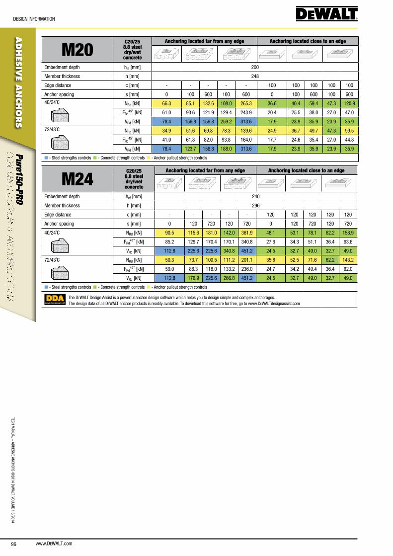
www.DEWALT.com96
TecH ManUal – aDHesIVe ancHoRs ©
2014 DeW
alT VolUMe 1 6/2014
ADHES
IVE A
NCHO
RS
DesIGn InfoRMaTIon
M20C20/25
8.8 steel dry/wetconcrete
Anchoring located far from any edge Anchoring located close to an edge
embedment depth hef [mm] 200
Member thickness h [mm] 248
edge distance c [mm] - - - - - 100 100 100 100 100
anchor spacing s [mm] 0 100 600 100 600 0 100 600 100 600
40/24˚c nRd [kn] 66.3 85.1 132.6 108.0 265.3 36.6 40.4 59.4 47.3 120.9
fRd45° [kn] 61.0 93.6 121.9 129.4 243.9 20.4 25.5 38.0 27.0 47.0
VRd [kn] 78.4 156.8 156.8 259.2 313.6 17.9 23.9 35.9 23.9 35.9
72/43˚c nRd [kn] 34.9 51.6 69.8 78.3 139.6 24.9 36.7 49.7 47.3 99.5
fRd45° [kn] 41.0 61.8 82.0 93.8 164.0 17.7 24.6 35.4 27.0 44.8
VRd [kn] 78.4 123.7 156.8 188.0 313.6 17.9 23.9 35.9 23.9 35.9
n - steel strengths controls n - concrete strength controls n - anchor pullout strength controls
M24C20/25
8.8 steel dry/wetconcrete
Anchoring located far from any edge Anchoring located close to an edge
embedment depth hef [mm] 240
Member thickness h [mm] 296
edge distance c [mm] - - - - - 120 120 120 120 120
anchor spacing s [mm] 0 120 720 120 720 0 120 720 120 720
40/24˚c nRd [kn] 90.5 115.6 181.0 142.0 361.9 48.1 53.1 78.1 62.2 158.9
fRd45° [kn] 85.2 129.7 170.4 170.1 340.8 27.6 34.3 51.1 36.4 63.6
VRd [kn] 112.8 225.6 225.6 340.8 451.2 24.5 32.7 49.0 32.7 49.0
72/43˚c nRd [kn] 50.3 73.7 100.5 111.2 201.1 35.8 52.5 71.6 62.2 143.2
fRd45° [kn] 59.0 88.3 118.0 133.2 236.0 24.7 34.2 49.4 36.4 62.0
VRd [kn] 112.8 176.9 225.6 266.8 451.2 24.5 32.7 49.0 32.7 49.0
n - steel strengths controls n - concrete strength controls n - anchor pullout strength controls
DEWALT DESIGN ASSIST
The DeWalT Design assist is a powerful anchor design software which helps you to design simple and complex anchorages.The design data of all DeWalT anchor products is readily available. To download this software for free, go to www.DeWalTdesignassist.com
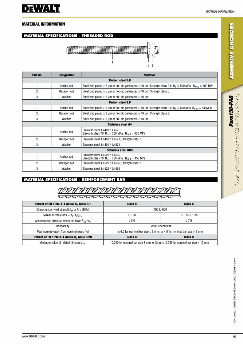
www.DEWALT.com 97
TecH
Man
Ual
– aD
HesI
Ve a
ncHo
Rs ©
2014
DeW
alT
Vol
UMe
1 6/
2014
ADHES
IVE
AN
CHO
RS
MaTeRIal InfoRMaTIon
MATERIAL INFORMATION
MATERIAL SPECIFICATIONS - THREADED ROD
231
Part no. Designation Material
Carbon steel 5.8
1 anchor rod steel zinc plated ≥ 5 μm or hot-dip galvanized ≥ 40 μm; strength class 5.8, Rm = 500 MPa ; Rp 0.2 = 400 MPa
2 Hexagon nut steel zinc plated ≥ 5 μm or hot-dip galvanized ≥ 40 μm; strength class 5
3 Washer steel zinc plated ≥ 5 μm or hot-dip galvanized ≥ 40 μm
Carbon steel 8.8
1 anchor rod steel zinc plated ≥ 5 μm or hot-dip galvanized ≥ 40 μm; strength class 8.8, Rm = 800 MPa; Rp 0.2 = 640MPa
2 Hexagon nut steel zinc plated ≥ 5 μm or hot-dip galvanized ≥ 40 μm; strength class 8
3 Washer steel zinc plated ≥ 5 μm or hot-dip galvanized ≥ 40 μm
Stainless steel A4
1 anchor rod stainless steel 1.4401 / 1.457strength class 70, Rm = 700 MPa ; Rp 0.2 = 450 MPa
2 Hexagon nut stainless steel 1.4401 / 1.4571; strength class 70
3 Washer stainless steel 1.4401 / 1.4571
Stainless steel HCR
1 anchor rod stainless steel 1.4529 / 1.4565strength class 70, Rm = 700 MPa ; Rp 0.2 = 450 MPa
2 Hexagon nut stainless steel 1.4529 / 1.4565; strength class 70
3 Washer stainless steel 1.4529 / 1.4565
MATERIAL SPECIFICATIONS - REINFORCEMENT BAR
Extract of EN 1992-1-1 Annex C, Table C.1 Class B Class C
characteristic yield strength fyk or f0.2k [MPa] 400 to 600
Minimum value of k = (ft / fy)k [-] ≥ 1.08 ≥ 1.15 < 1.35
characteristic strain at maximum force euk [%] ≥ 5.0 ≥ 7.5
bendability bend/Rebend test
Maximum deviation from nominal mass [%] ± 6.0 for nominal bar size ≤ 8 mm; ± 4.5 for nominal bar size > 8 mm
Extract of EN 1992-1-1 Annex C, Table C.2N Class B Class C
Minimum value of related rib area fR,min 0.040 for nominal bar size 8 mm to 12 mm; 0.056 for nominal bar size > 12 mm
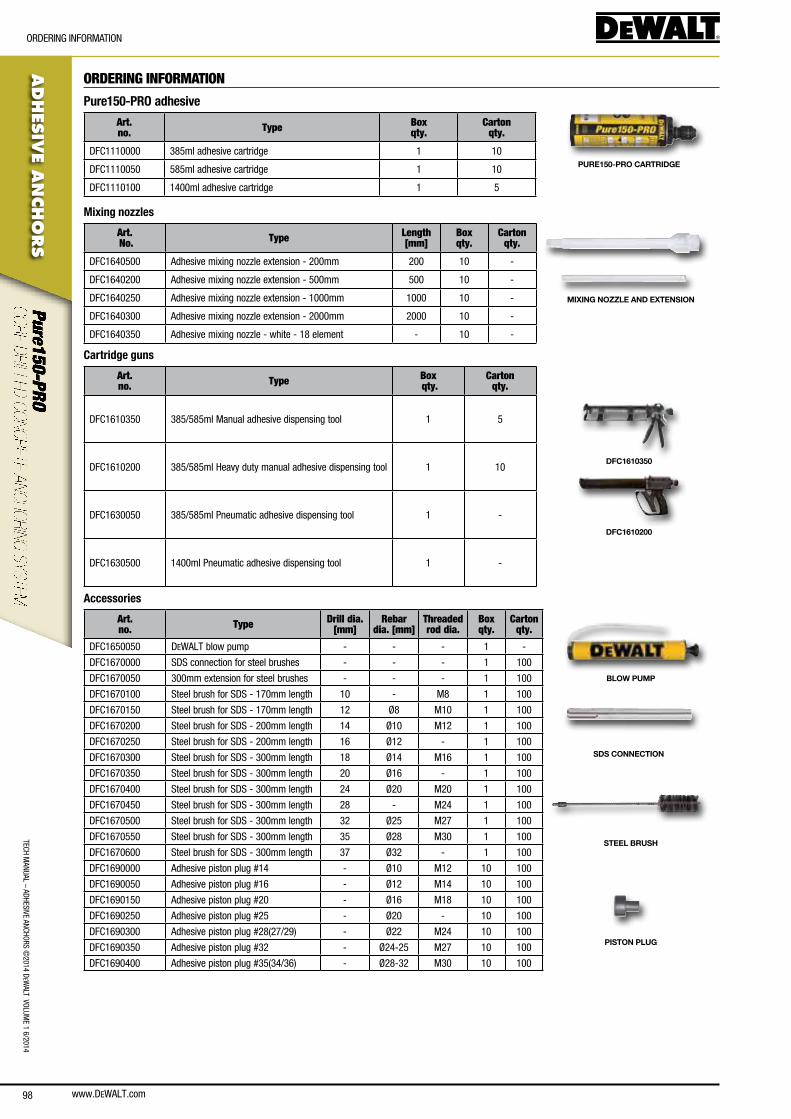
www.DEWALT.com98
TecH ManUal – aDHesIVe ancHoRs ©
2014 DeW
alT VolUMe 1 6/2014
ADHES
IVE A
NCHO
RS
oRDeRInG InfoRMaTIon
ORDERING INFORMATION
Pure150-PRO adhesive
Art. no. Type Box
qty.Carton
qty.
Dfc1110000 385ml adhesive cartridge 1 10
Dfc1110050 585ml adhesive cartridge 1 10
Dfc1110100 1400ml adhesive cartridge 1 5
PURE150-PRO CARTRIDGE
Mixing nozzles
Art. No. Type Length
[mm] Box qty.
Carton qty.
Dfc1640500 adhesive mixing nozzle extension - 200mm 200 10 -
Dfc1640200 adhesive mixing nozzle extension - 500mm 500 10 -
Dfc1640250 adhesive mixing nozzle extension - 1000mm 1000 10 -
Dfc1640300 adhesive mixing nozzle extension - 2000mm 2000 10 -
Dfc1640350 adhesive mixing nozzle - white - 18 element - 10 -
MIXING NOZZLE AND EXTENSION
Cartridge guns
Art. no. Type Box
qty.Carton
qty.
Dfc1610350 385/585ml Manual adhesive dispensing tool 1 5
Dfc1610200 385/585ml Heavy duty manual adhesive dispensing tool 1 10
Dfc1630050 385/585ml Pneumatic adhesive dispensing tool 1 -
Dfc1630500 1400ml Pneumatic adhesive dispensing tool 1 -
DFC1610350
DFC1610200
Accessories
Art. no. Type Drill dia.
[mm]Rebar
dia. [mm]Threaded rod dia.
Box qty.
Carton qty.
Dfc1650050 DeWalT blow pump - - - 1 -
Dfc1670000 sDs connection for steel brushes - - - 1 100
Dfc1670050 300mm extension for steel brushes - - - 1 100
Dfc1670100 steel brush for sDs - 170mm length 10 - M8 1 100
Dfc1670150 steel brush for sDs - 170mm length 12 Ø8 M10 1 100
Dfc1670200 steel brush for sDs - 200mm length 14 Ø10 M12 1 100
Dfc1670250 steel brush for sDs - 200mm length 16 Ø12 - 1 100
Dfc1670300 steel brush for sDs - 300mm length 18 Ø14 M16 1 100
Dfc1670350 steel brush for sDs - 300mm length 20 Ø16 - 1 100
Dfc1670400 steel brush for sDs - 300mm length 24 Ø20 M20 1 100
Dfc1670450 steel brush for sDs - 300mm length 28 - M24 1 100
Dfc1670500 steel brush for sDs - 300mm length 32 Ø25 M27 1 100
Dfc1670550 steel brush for sDs - 300mm length 35 Ø28 M30 1 100
Dfc1670600 steel brush for sDs - 300mm length 37 Ø32 - 1 100
Dfc1690000 adhesive piston plug #14 - Ø10 M12 10 100
Dfc1690050 adhesive piston plug #16 - Ø12 M14 10 100
Dfc1690150 adhesive piston plug #20 - Ø16 M18 10 100
Dfc1690250 adhesive piston plug #25 - Ø20 - 10 100
Dfc1690300 adhesive piston plug #28(27/29) - Ø22 M24 10 100
Dfc1690350 adhesive piston plug #32 - Ø24-25 M27 10 100
Dfc1690400 adhesive piston plug #35(34/36) - Ø28-32 M30 10 100
BLOW PUMP
SDS CONNECTION
STEEL BRUSH
PISTON PLUG
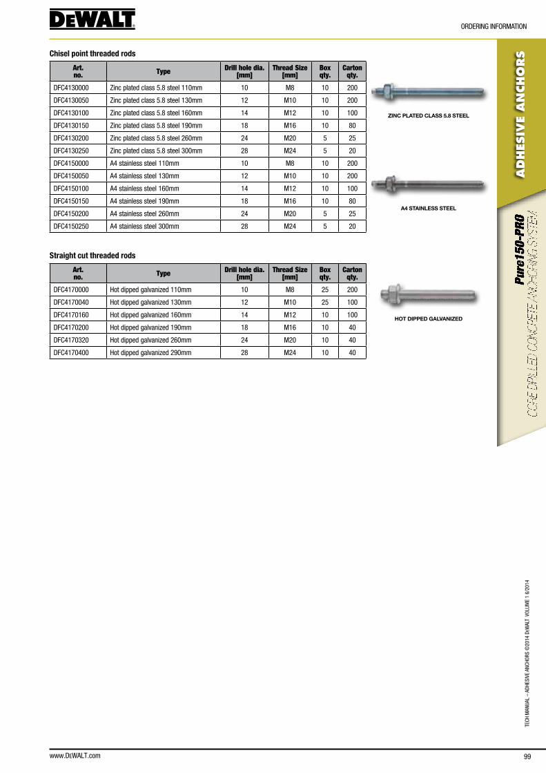
www.DEWALT.com 99
TecH
Man
Ual
– aD
HesI
Ve a
ncHo
Rs ©
2014
DeW
alT
Vol
UMe
1 6/
2014
ADHES
IVE
AN
CHO
RS
oRDeRInG InfoRMaTIon
Chisel point threaded rods
Art. no. Type Drill hole dia.
[mm]Thread Size
[mm]Box qty.
Carton qty.
Dfc4130000 Zinc plated class 5.8 steel 110mm 10 M8 10 200
Dfc4130050 Zinc plated class 5.8 steel 130mm 12 M10 10 200
Dfc4130100 Zinc plated class 5.8 steel 160mm 14 M12 10 100
Dfc4130150 Zinc plated class 5.8 steel 190mm 18 M16 10 80
Dfc4130200 Zinc plated class 5.8 steel 260mm 24 M20 5 25
Dfc4130250 Zinc plated class 5.8 steel 300mm 28 M24 5 20
Dfc4150000 a4 stainless steel 110mm 10 M8 10 200
Dfc4150050 a4 stainless steel 130mm 12 M10 10 200
Dfc4150100 a4 stainless steel 160mm 14 M12 10 100
Dfc4150150 a4 stainless steel 190mm 18 M16 10 80
Dfc4150200 a4 stainless steel 260mm 24 M20 5 25
Dfc4150250 a4 stainless steel 300mm 28 M24 5 20
Straight cut threaded rods
Art. no. Type Drill hole dia.
[mm]Thread Size
[mm]Box qty.
Carton qty.
Dfc4170000 Hot dipped galvanized 110mm 10 M8 25 200
Dfc4170040 Hot dipped galvanized 130mm 12 M10 25 100
Dfc4170160 Hot dipped galvanized 160mm 14 M12 10 100
Dfc4170200 Hot dipped galvanized 190mm 18 M16 10 40
Dfc4170320 Hot dipped galvanized 260mm 24 M20 10 40
Dfc4170400 Hot dipped galvanized 290mm 28 M24 10 40
ZINC PLATED CLASS 5.8 STEEL
A4 STAINLESS STEEL
HOT DIPPED GALVANIZED
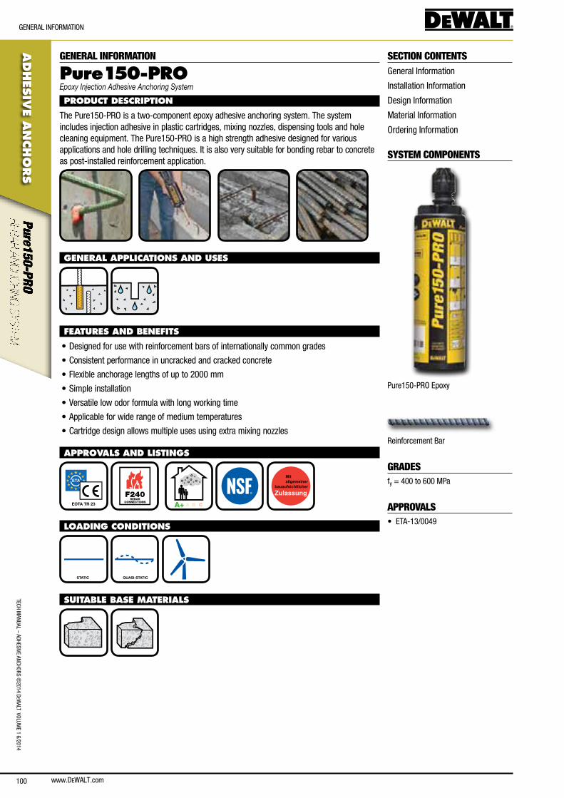
www.DEWALT.com100
TecH ManUal – aDHesIVe ancHoRs ©
2014 DeW
alT VolUMe 1 6/2014
ADHES
IVE A
NCHO
RS
GeneRal InfoRMaTIon
SECTION CONTENTSGeneral Information
Installation Information
Design Information
Material Information
ordering Information
SYSTEM COMPONENTS
Pure150-PRo epoxy
Reinforcement bar
GRADESfy = 400 to 600 MPa
APPROVALS• eTa-13/0049
GENERAL INFORMATION
Pure15 0-PROEpoxy Injection Adhesive Anchoring System
PRODUCT DESCRIPTION
The Pure150-PRo is a two-component epoxy adhesive anchoring system. The system includes injection adhesive in plastic cartridges, mixing nozzles, dispensing tools and hole cleaning equipment. The Pure150-PRo is a high strength adhesive designed for various applications and hole drilling techniques. It is also very suitable for bonding rebar to concrete as post-installed reinforcement application.
GENERAL APPLICATIONS AND USES
FEATURES AND BENEFITS
• Designed for use with reinforcement bars of internationally common grades
• consistent performance in uncracked and cracked concrete
• flexible anchorage lengths of up to 2000 mm
• simple installation
• Versatile low odor formula with long working time
• applicable for wide range of medium temperatures
• cartridge design allows multiple uses using extra mixing nozzles
APPROVALS AND LISTINGS
EOTA TR 23 F240
REBARCONNECTIONS
A+ A B C
LOADING CONDITIONS
STATIC QUASI-STATIC
SUITABLE BASE MATERIALS
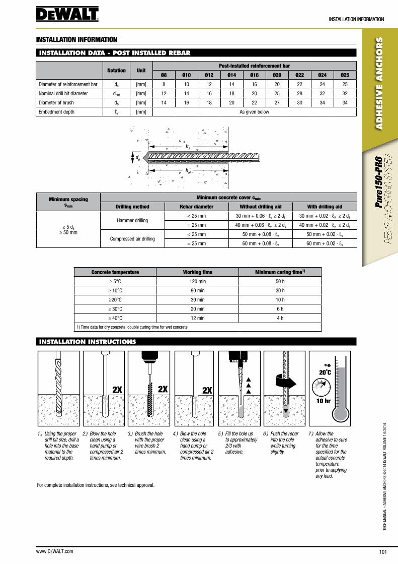
www.DEWALT.com 101
ADHES
IVE
AN
CHO
RS
InsTallaTIon InfoRMaTIon
TecH
Man
Ual
– aD
HesI
Ve a
ncHo
Rs ©
2014
DeW
alT
Vol
UMe
1 6/
2014
InsTallaTIon InfoRMaTIon
INSTALLATION INFORMATION
INSTALLATION DATA - POST INSTALLED REBAR
Notation UnitPost-installed reinforcement bar
Ø8 Ø10 Ø12 Ø14 Ø16 Ø20 Ø22 Ø24 Ø25
Diameter of reinforcement bar ds [mm] 8 10 12 14 16 20 22 24 25
nominal drill bit diameter dcut [mm] 12 14 16 18 20 25 28 32 32
Diameter of brush db [mm] 14 16 18 20 22 27 30 34 34
embedment depth ℓv [mm] as given below
hef
d0
h1
Minimum spacingsmin
Minimum concrete cover cmin
Drilling method Rebar diameter Without drilling aid With drilling aid
≥ 5 ds≥ 50 mm
Hammer drilling< 25 mm 30 mm + 0.06 · ℓv ≥ 2 ds 30 mm + 0.02 · ℓv ≥ 2 ds
= 25 mm 40 mm + 0.06 · ℓv ≥ 2 ds 40 mm + 0.02 · ℓv ≥ 2 ds
compressed air drilling< 25 mm 50 mm + 0.08 · ℓv 50 mm + 0.02 · ℓv
= 25 mm 60 mm + 0.08 · ℓv 60 mm + 0.02 · ℓv
Concrete temperature Working time Minimum curing time1)
≥ 5°c 120 min 50 h
≥ 10°c 90 min 30 h
≥20°c 30 min 10 h
≥ 30°c 20 min 6 h
≥ 40°c 12 min 4 h
1) Time data for dry concrete, double curing time for wet concrete
INSTALLATION INSTRUCTIONS
2X 2X 2X
e.g.
20˚C
10 hr
1.) Using the proper drill bit size, drill a hole into the base material to the required depth.
2.) Blow the hole clean using a hand pump or compressed air 2 times minimum.
3.) Brush the hole with the proper wire brush 2 times minimum.
4.) Blow the hole clean using a hand pump or compressed air 2 times minimum.
5.) Fill the hole up to approximately 2/3 with adhesive.
6.) Push the rebar into the hole while turning slightly.
7.) Allow the adhesive to cure for the time specified for the actual concrete temperature prior to applying any load.
for complete installation instructions, see technical approval.
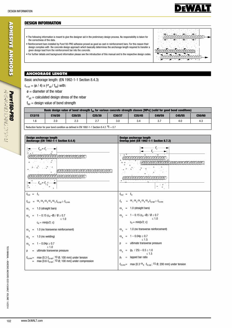
www.DEWALT.com102
TecH ManUal – aDHesIVe ancHoRs ©
2014 DeW
alT VolUMe 1 6/2014
ADHES
IVE A
NCHO
RS
DesIGn InfoRMaTIon
DESIGN INFORMATION
• The following information is meant to give the designer aid in the preliminary design process. no responsibility is taken for the correctness of the data.
• Reinforcement bars installed by Pure150-PRo adhesive proved as good as cast-in reinforcement bars. for this reason their design complies with the concrete design approach which basically determines the anchorage length required to transfer a given design load from the reinforcement bar into the concrete.
• for further details and background information please see the introduction of this manual and to the respective design codes.
ANCHORAGE LENGTH
basic anchorage length: (en 1992-1-1 section 8.4.3)
ℓb,rqd = (ø / 4) x (ssd / fbd) with:
ø = diameter of the rebar
ssd = calculated design stress of the rebar
fbd = design value of bond strength
Basic design value of bond strength fbd for various concrete strength classes [MPa] (valid for good bond conditons)
C12/15 C16/20 C20/25 C25/30 C30/37 C35/45 C49/59 C45/55 C50/60
1.6 2.0 2.3 2.7 3.0 3.4 3.7 4.0 4.3
Reduction factor for poor bond condition as defined in en 1992-1-1 section 8.4.2: h = 0.7
Design anchorage lengthAnchorage (EN 1992-1-1 Section 8.4.4)
Design anchorage lengthOverlap joint (EN 1992-1-1 Section 8.7.3)
ℓb,d = ℓv
ℓb,d = ℓv
ℓvℓ0
ℓb,d = ℓv
ℓb,d = a
1 a
2 a
3 a
4 a
5 ℓb,rqd ≥ ℓb,min
a1 = 1.0 (straight bars)
a2 = 1 – 0.15 (cd –Ø) / Ø ≥ 0.7
≤ 1.0 cd = min{s/2; c}
a3 = 1.0 (no transverse reinforcement)
a4 = 1.0 (no welding)
a5 = 1 – 0.04p ≥ 0.7
≤ 1.0p = ultimate transverse pressure
ℓb,min = max {0.3 ℓb,rqd ; 10 Ø; 100 mm} under tension = max {0.6 ℓb,rqd ; 10 Ø; 100 mm} under compression
ℓb,d = ℓo
ℓo = a
1 a
2 a
3 a
5 a
6 ℓb,rqd ≥ ℓ0,min
a1 = 1.0 (straight bars)
a2 = 1 – 0.15 (cd –Ø) / Ø ≥ 0.7
≤ 1.0 cd = min{s/2; c}
a3 = 1.0 (no transverse reinforcement)
a4 = 1 – 0.04p ≥ 0.7
≤ 1.5p = ultimate transverse pressure
a5 = (pt / 25) – 0.5 ≥ 1.0
≤ 1.5pt = lapped bar ratio
ℓ0,min = max {0.3 a6 ℓb,rqd ; 15 Ø; 200 mm} under tension
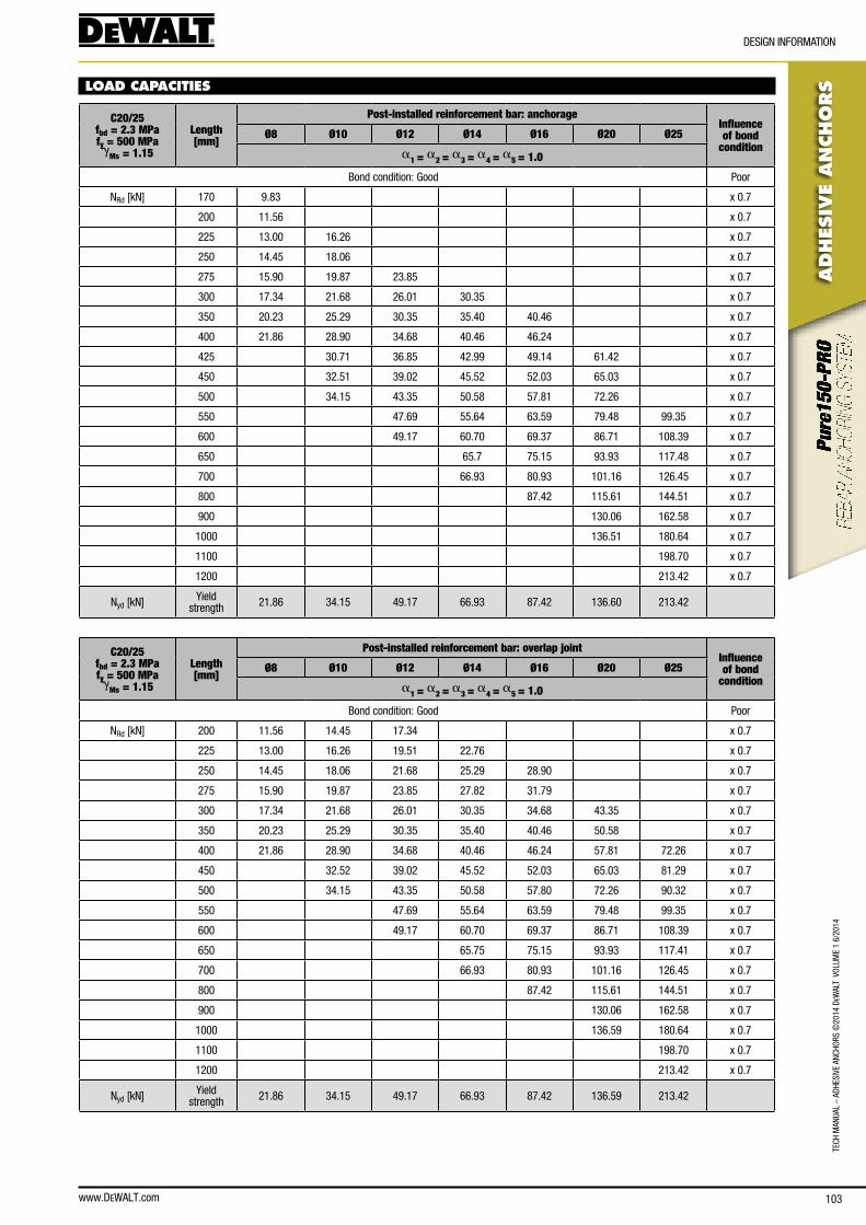
www.DEWALT.com 103
TecH
Man
Ual
– aD
HesI
Ve a
ncHo
Rs ©
2014
DeW
alT
Vol
UMe
1 6/
2014
ADHES
IVE
AN
CHO
RS
DesIGn InfoRMaTIon
LOAD CAPACITIES
C20/25fbd = 2.3 MPa fy = 500 MPa g
Ms = 1.15
Length [mm]
Post-installed reinforcement bar: anchorageInfluence of bond
conditionØ8 Ø10 Ø12 Ø14 Ø16 Ø20 Ø25
a1 = a2 = a3 = a4 = a5 = 1.0
bond condition: Good Poor
nRd [kn] 170 9.83 x 0.7
200 11.56 x 0.7
225 13.00 16.26 x 0.7
250 14.45 18.06 x 0.7
275 15.90 19.87 23.85 x 0.7
300 17.34 21.68 26.01 30.35 x 0.7
350 20.23 25.29 30.35 35.40 40.46 x 0.7
400 21.86 28.90 34.68 40.46 46.24 x 0.7
425 30.71 36.85 42.99 49.14 61.42 x 0.7
450 32.51 39.02 45.52 52.03 65.03 x 0.7
500 34.15 43.35 50.58 57.81 72.26 x 0.7
550 47.69 55.64 63.59 79.48 99.35 x 0.7
600 49.17 60.70 69.37 86.71 108.39 x 0.7
650 65.7 75.15 93.93 117.48 x 0.7
700 66.93 80.93 101.16 126.45 x 0.7
800 87.42 115.61 144.51 x 0.7
900 130.06 162.58 x 0.7
1000 136.51 180.64 x 0.7
1100 198.70 x 0.7
1200 213.42 x 0.7
nyd [kn] yield strength 21.86 34.15 49.17 66.93 87.42 136.60 213.42
C20/25fbd = 2.3 MPa fy = 500 MPa g
Ms = 1.15
Length [mm]
Post-installed reinforcement bar: overlap jointInfluence of bond
conditionØ8 Ø10 Ø12 Ø14 Ø16 Ø20 Ø25
a1 = a2 = a3 = a4 = a5 = 1.0
bond condition: Good Poor
nRd [kn] 200 11.56 14.45 17.34 x 0.7
225 13.00 16.26 19.51 22.76 x 0.7
250 14.45 18.06 21.68 25.29 28.90 x 0.7
275 15.90 19.87 23.85 27.82 31.79 x 0.7
300 17.34 21.68 26.01 30.35 34.68 43.35 x 0.7
350 20.23 25.29 30.35 35.40 40.46 50.58 x 0.7
400 21.86 28.90 34.68 40.46 46.24 57.81 72.26 x 0.7
450 32.52 39.02 45.52 52.03 65.03 81.29 x 0.7
500 34.15 43.35 50.58 57.80 72.26 90.32 x 0.7
550 47.69 55.64 63.59 79.48 99.35 x 0.7
600 49.17 60.70 69.37 86.71 108.39 x 0.7
650 65.75 75.15 93.93 117.41 x 0.7
700 66.93 80.93 101.16 126.45 x 0.7
800 87.42 115.61 144.51 x 0.7
900 130.06 162.58 x 0.7
1000 136.59 180.64 x 0.7
1100 198.70 x 0.7
1200 213.42 x 0.7
nyd [kn] yield strength 21.86 34.15 49.17 66.93 87.42 136.59 213.42
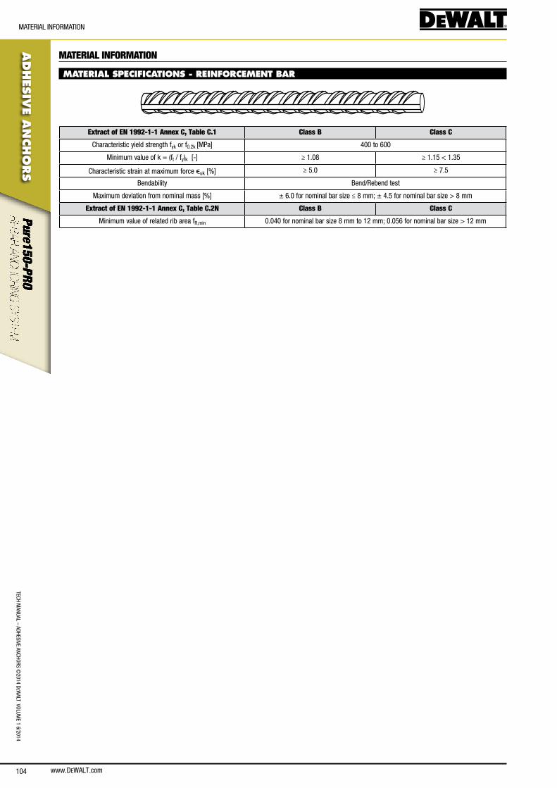
www.DEWALT.com104
TecH ManUal – aDHesIVe ancHoRs ©
2014 DeW
alT VolUMe 1 6/2014
ADHES
IVE A
NCHO
RS
MaTeRIal InfoRMaTIon
MATERIAL INFORMATION
MATERIAL SPECIFICATIONS - REINFORCEMENT BAR
Extract of EN 1992-1-1 Annex C, Table C.1 Class B Class C
characteristic yield strength fyk or f0.2k [MPa] 400 to 600
Minimum value of k = (ft / fy)k [-] ≥ 1.08 ≥ 1.15 < 1.35
characteristic strain at maximum force euk [%] ≥ 5.0 ≥ 7.5
bendability bend/Rebend test
Maximum deviation from nominal mass [%] ± 6.0 for nominal bar size ≤ 8 mm; ± 4.5 for nominal bar size > 8 mm
Extract of EN 1992-1-1 Annex C, Table C.2N Class B Class C
Minimum value of related rib area fR,min 0.040 for nominal bar size 8 mm to 12 mm; 0.056 for nominal bar size > 12 mm

www.DEWALT.com 105
TecH
Man
Ual
– aD
HesI
Ve a
ncHo
Rs ©
2014
DeW
alT
Vol
UMe
1 6/
2014
ADHES
IVE
AN
CHO
RS
oRDeRInG InfoRMaTIon
ORDERING INFORMATION
Pure150-PRO adhesive
Art. no. Type Box
qty.Carton
qty.
Dfc1110000 385ml adhesive cartridge 1 10
Dfc1110050 585ml adhesive cartridge 1 10
Dfc1110100 1400ml adhesive cartridge 1 5
PURE150-PRO CARTRIDGE
Mixing nozzles
Art. No. Type Length
[mm]Box qty.
Carton qty.
Dfc1640500 adhesive mixing nozzle extension - 200mm 200 10 -
Dfc1640200 adhesive mixing nozzle extension - 500mm 500 10 -
Dfc1640250 adhesive mixing nozzle extension - 1000mm 1000 10 -
Dfc1640300 adhesive mixing nozzle extension - 2000mm 2000 10 -
Dfc1640350 adhesive mixing nozzle - white - 18 element - 10 -
MIXING NOZZLE AND EXTENSION
Cartridge guns
Art. no. Type Box
qty.Carton
qty.
Dfc1610350 385/585ml Manual adhesive dispensing tool 1 5
Dfc1610200 385/585ml Heavy duty manual adhesive dispensing tool 1 10
Dfc1630050 385/585ml Pneumatic adhesive dispensing tool 1 -
Dfc1630500 1400ml Pneumatic adhesive dispensing tool 1 -
DFC1610350
DFC1610200
Accessories
Art. no. Type Drill dia.
[mm]Rebar
dia. [mm]Threaded rod dia.
Box qty.
Carton qty.
Dfc1650050 DeWalT blow pump - - - 1 -
Dfc1670000 sDs connection for steel brushes - - - 1 100
Dfc1670050 300mm extension for steel brushes - - - 1 100
Dfc1670100 steel brush for sDs - 170mm length 10 - M8 1 100
Dfc1670150 steel brush for sDs - 170mm length 12 Ø8 M10 1 100
Dfc1670200 steel brush for sDs - 200mm length 14 Ø10 M12 1 100
Dfc1670250 steel brush for sDs - 200mm length 16 Ø12 - 1 100
Dfc1670300 steel brush for sDs - 300mm length 18 Ø14 M16 1 100
Dfc1670350 steel brush for sDs - 300mm length 20 Ø16 - 1 100
Dfc1670400 steel brush for sDs - 300mm length 24 Ø20 M20 1 100
Dfc1670450 steel brush for sDs - 300mm length 28 - M24 1 100
Dfc1670500 steel brush for sDs - 300mm length 32 Ø25 M27 1 100
Dfc1670550 steel brush for sDs - 300mm length 35 Ø28 M30 1 100
Dfc1670600 steel brush for sDs - 300mm length 37 Ø32 - 1 100
Dfc1690000 adhesive piston plug #14 - Ø10 M12 10 100
Dfc1690050 adhesive piston plug #16 - Ø12 M14 10 100
Dfc1690150 adhesive piston plug #20 - Ø16 M18 10 100
Dfc1690250 adhesive piston plug #25 - Ø20 - 10 100
Dfc1690300 adhesive piston plug #28(27/29) - Ø22 M24 10 100
Dfc1690350 adhesive piston plug #32 - Ø24-25 M27 10 100
Dfc1690400 adhesive piston plug #35(34/36) - Ø28-32 M30 10 100
BLOW PUMP
SDS CONNECTION
STEEL BRUSH
PISTON PLUG
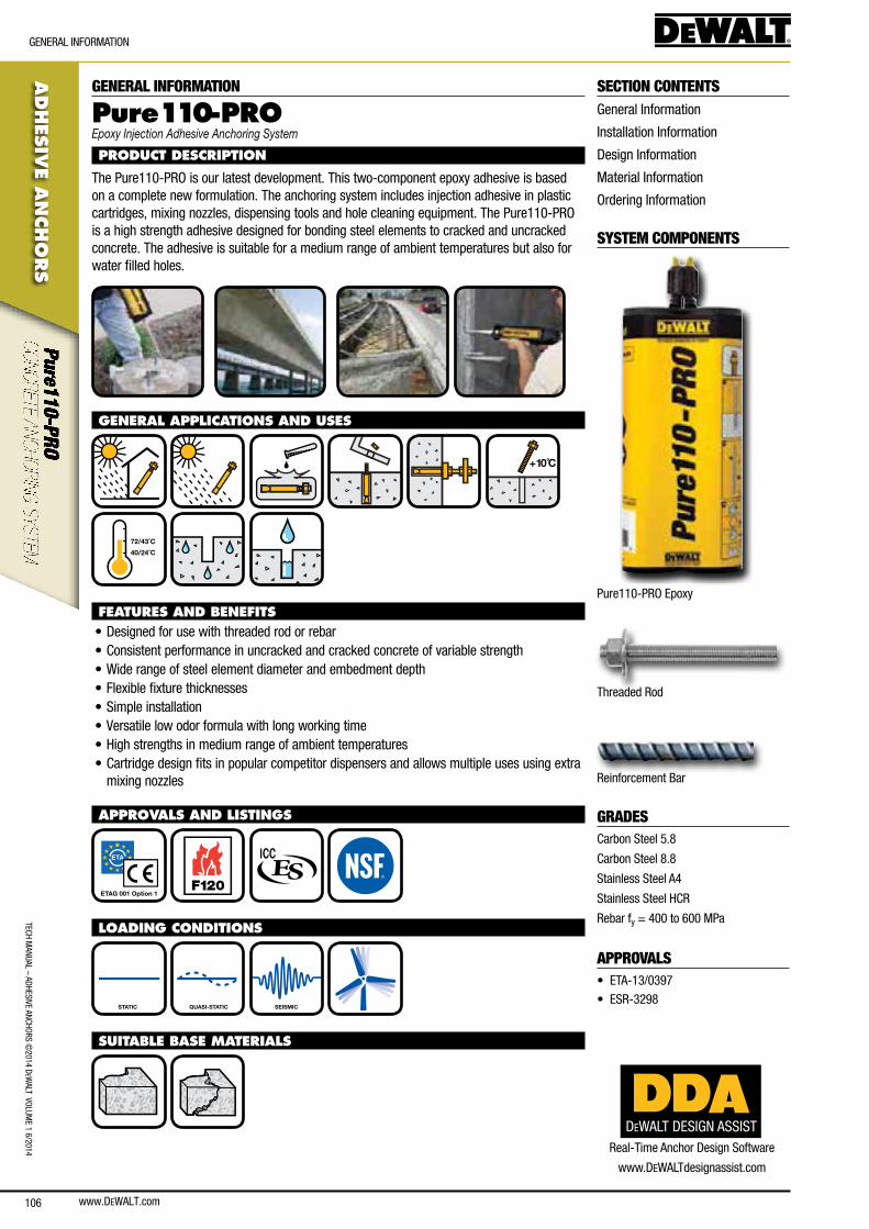
106
TecH ManUal – aDHesIVe ancHoRs ©
2014 DeW
alT VolUMe 1 6/2014
ADHES
IVE A
NCHO
RS
GeneRal InfoRMaTIon
GENERAL INFORMATION
Pure110-PROEpoxy Injection Adhesive Anchoring System
PRODUCT DESCRIPTION
The Pure110-PRo is our latest development. This two-component epoxy adhesive is based on a complete new formulation. The anchoring system includes injection adhesive in plastic cartridges, mixing nozzles, dispensing tools and hole cleaning equipment. The Pure110-PRo is a high strength adhesive designed for bonding steel elements to cracked and uncracked concrete. The adhesive is suitable for a medium range of ambient temperatures but also for water filled holes.
GENERAL APPLICATIONS AND USES
+10C̊
40/24˚C
72/43˚C
FEATURES AND BENEFITS• Designed for use with threaded rod or rebar• consistent performance in uncracked and cracked concrete of variable strength• Wide range of steel element diameter and embedment depth• flexible fixture thicknesses• simple installation• Versatile low odor formula with long working time• High strengths in medium range of ambient temperatures• cartridge design fits in popular competitor dispensers and allows multiple uses using extra
mixing nozzles
APPROVALS AND LISTINGS
ETAG 001 Option 1 F120
LOADING CONDITIONS
STATIC QUASI-STATIC SEISMIC
SUITABLE BASE MATERIALS
SECTION CONTENTSGeneral Information
Installation Information
Design Information
Material Information
ordering Information
SYSTEM COMPONENTS
Pure110-PRo epoxy
Threaded Rod
Reinforcement bar
GRADEScarbon steel 5.8
carbon steel 8.8
stainless steel a4
stainless steel HcR
Rebar fy = 400 to 600 MPa
APPROVALS• eTa-13/0397
• esR-3298
www.DeWalT.com
DEWALT DESIGN ASSISTReal-Time anchor Design software
www.DeWalTdesignassist.com
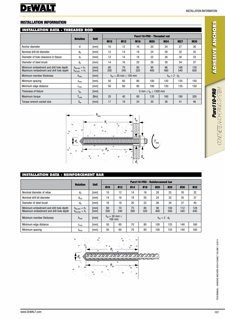
www.DEWALT.com 107
ADHES
IVE
AN
CHO
RS
InsTallaTIon InfoRMaTIon
TecH
Man
Ual
– aD
HesI
Ve a
ncHo
Rs ©
2014
DeW
alT
Vol
UMe
1 6/
2014
INSTALLATION INFORMATION
INSTALLATION DATA - THREADED ROD
Notation UnitPure110-PRO - Threaded rod
M10 M12 M16 M20 M24 M27 M30
anchor diameter d [mm] 10 12 16 20 24 27 30
nominal drill bit diameter d0 [mm] 12 14 18 24 28 32 35
Diameter of hole clearance in fixture df [mm] 12 14 18 22 26 30 33
Diameter of steel brush db [mm] 14 16 20 26 30 34 37
Minimum embedment and drill hole depth Maximum embedment and drill hole depth
hef,min = h1 hef,min = h1
[mm] [mm]
60 200
70 240
80 320
90 400
96 480
108 540
120 600
Minimum member thickness hmin [mm] hef + 30 mm ≥ 100 mm hef + 2 · d0
Minimum spacing smin [mm] 50 60 80 100 120 135 150
Minimum edge distance cmin [mm] 50 60 80 100 120 135 150
Thickness of fixture tfix [mm] 0 mm ≤ tfix ≤ 1500 mm
Maximum torque Tmax [nm] 20 40 80 120 160 180 200
Torque wrench socket size sw [mm] 17 19 24 30 36 41 46
hmin
h1
hef
d0
Sw
Tmax
df
tfix
INSTALLATION DATA - REINFORCEMENT BAR
Notation UnitPure110-PRO - Reinforcement bar
Ø10 Ø12 Ø14 Ø16 Ø20 Ø25 Ø30 Ø32
nominal diameter of rebar d0 [mm] 10 12 14 16 20 25 30 32
nominal drill bit diameter dcut [mm] 14 16 18 20 24 32 35 37
Diameter of steel brush db [mm] 16 18 20 22 26 34 37 40
Minimum embedment and drill hole depth Maximum embedment and drill hole depth
hef,min = h1 hef,max = h1
[mm] [mm]
60 200
70 240
75 280
80 320
90 400
100 500
112 540
128 640
Minimum member thickness hmin [mm] hef + 30 mm ≥ 100 mm hef + 2 · d0
Minimum edge distance cmin [mm] 50 60 70 80 100 125 140 160
Minimum spacing smin [mm] 50 60 70 80 100 125 140 160
hef
d0
h1
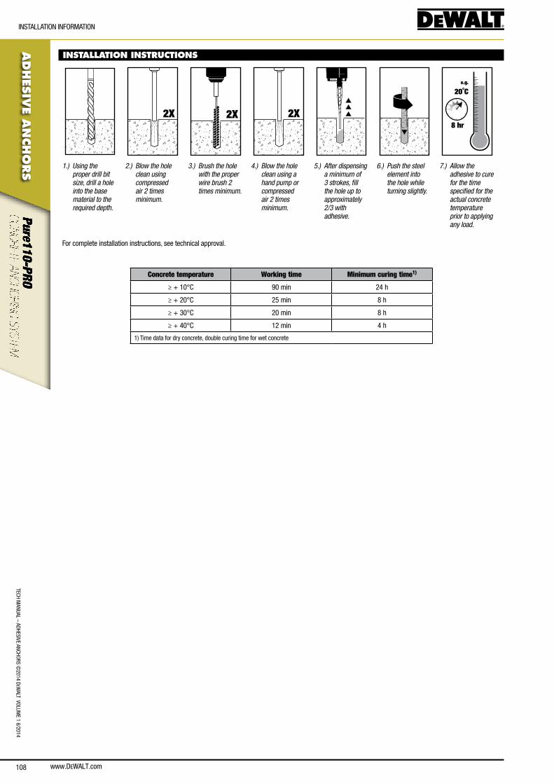
108
ADHES
IVE A
NCHO
RS
InsTallaTIon InfoRMaTIon
TecH ManUal – aDHesIVe ancHoRs ©
2014 DeW
alT VolUMe 1 6/2014
www.DeWalT.com
INSTALLATION INSTRUCTIONS
2X 2X 2X
e.g.
20˚C
8 hr
1.) Using the proper drill bit size, drill a hole into the base material to the required depth.
2.) Blow the hole clean using compressed air 2 times minimum.
3.) Brush the hole with the proper wire brush 2 times minimum.
4.) Blow the hole clean using a hand pump or compressed air 2 times minimum.
5.) After dispensing a minimum of 3 strokes, fill the hole up to approximately 2/3 with adhesive.
6.) Push the steel element into the hole while turning slightly.
7.) Allow the adhesive to cure for the time specified for the actual concrete temperature prior to applying any load.
for complete installation instructions, see technical approval.
Concrete temperature Working time Minimum curing time1)
≥ + 10°c 90 min 24 h
≥ + 20°c 25 min 8 h
≥ + 30°c 20 min 8 h
≥ + 40°c 12 min 4 h
1) Time data for dry concrete, double curing time for wet concrete
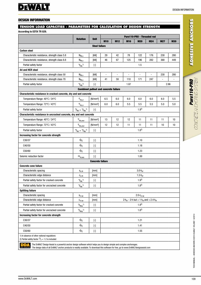
www.DEWALT.com 109
TecH
Man
Ual
– aD
HesI
Ve a
ncHo
Rs ©
2014
DeW
alT
Vol
UMe
1 6/
2014
ADHES
IVE
AN
CHO
RS
DesIGn InfoRMaTIon
DESIGN INFORMATION
TENSION LOAD CAPACITIES - PARAMETERS FOR CALCULATION OF DESIGN STRENGTHAccording to EOTA TR 029.
Notation UnitPure110-PRO - Threaded rod
M10 M12 M16 M20 M24 M27 M30
Steel failure
Carbon steel
characteristic resistance, strength class 5.8 nRk,s [kn] 29 42 78 122 176 230 280
characteristic resistance, strength class 8.8 nRk,s [kn] 46 67 125 196 282 368 449
Partial safety factor gMs
1) [-] 1.5
A4 and HCR steel
characteristic resistance, strength class 50 nRk,s [kn] - - - - - 230 280
characteristic resistance, strength class 70 nRk,s [kn] 41 59 110 171 247 - -
Partial safety factor gMs
1) [-] 1.87 2.86
Combined pullout and concrete failure
Characteristic resistance in cracked concrete, dry and wet concrete
Temperature Range: 40°c / 24°c tRk,cr [n/mm²] 6.5 6.0 6.0 6.0 6.0 6.0 5.5
Temperature Range: 72°c / 43°c tRk,cr [n/mm²] 6.0 6.0 5.5 5.5 5.5 5.0 5.0
Partial safety factor gMc = gMp
1) [-] 1.92)
Characteristic resistance in uncracked concrete, dry and wet concrete
Temperature Range: 40°c / 24°c tRk,uncr [n/mm²] 13 12 12 11 11 11 10
Temperature Range: 72°c / 43°c tRk,uncr [n/mm²] 12 12 11 11 11 10 10
Partial safety factor gMc = gMp
1) [-] 1.82)
Increasing factor for concrete strength
c30/37 cc [-] 1.10
c40/50 cc [-] 1.18
c50/60 cc [-] 1.23
seismic reduction factor an,seis [-] 1.00
Concrete failure
Concrete cone failure
characteristic spacing scr,n [mm] 3.0·hef
characteristic edge distance ccr,n [mm] 1.5·hef
Partial safety factor for cracked concrete gMc
1) [-] 1.92)
Partial safety factor for uncracked concrete gMc
1) [-] 1.82)
Splitting failure
characteristic spacing scr,sp [mm] 2.0·ccr,sp
characteristic edge distance ccr,sp [mm] 2·hef - 2·h but ≥ 1·hef and ≤ 2.4·hef
Partial safety factor for cracked concrete gMsp
1) [-] 1.92)
Partial safety factor for uncracked concrete gMsp
1) [-] 1.82)
Increasing factor for concrete strength
c30/37 cc [-] 1.21
c40/50 cc [-] 1.41
c50/60 cc [-] 1.55
1) In absence of other national regulations
2) Partial safety factor g2 = 1.2 is included
DEWALT DESIGN ASSIST
The DeWalT Design assist is a powerful anchor design software which helps you to design simple and complex anchorages.The design data of all DeWalT anchor products is readily available. To download this software for free, go to www.DeWalTdesignassist.com
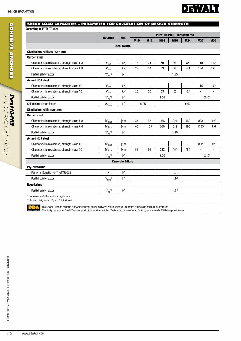
www.DEWALT.com110
TecH ManUal – aDHesIVe ancHoRs ©
2014 DeW
alT VolUMe 1 6/2014
ADHES
IVE A
NCHO
RS
DesIGn InfoRMaTIon
SHEAR LOAD CAPACITIES - PARAMETER FOR CALCULATION OF DESIGN STRENGTHAccording to EOTA TR 029.
Notation UnitPure110-PRO - Threaded rod
M10 M12 M16 M20 M24 M27 M30
Steel failure
Steel failure without lever arm
Carbon steel
characteristic resistance, strength class 5.8 VRk,s [kn] 15 21 39 61 88 115 140
characteristic resistance, strength class 8.8 VRk,s [kn] 23 34 63 98 141 184 224
Partial safety factor gMs
1) [-] 1.25
A4 and HCR steel
characteristic resistance, strength class 50 VRk,s [kn] - - - - - 115 140
characteristic resistance, strength class 70 VRk,s [kn] 20 30 55 86 124 - -
Partial safety factor gMs
1) [-] 1.56 2.17
seismic reduction factor aV,seis [-] 0.95 0.93
Steel failure with lever arm
Carbon steel
characteristic resistance, strength class 5.8 M0Rk,s [nm] 37 65 166 324 560 833 1123
characteristic resistance, strength class 8.8 M0Rk,s [nm] 60 105 266 519 896 1333 1797
Partial safety factor gMs
1) [-] 1.25
A4 and HCR steel
characteristic resistance, strength class 50 M0Rk,s [nm] - - - - - 832 1125
characteristic resistance, strength class 70 M0Rk,s [nm] 52 92 232 454 784 - -
Partial safety factor gMs
1) [-] 1.56 2.17
Concrete failure
Pry-out failure
factor in equation (5.7) of TR 029 k [-] 2
Partial safety factor gMcp
1) [-] 1.52)
Edge failure
Partial safety factor gMc
1) [-] 1.52)
1) In absence of other national regulations
2) Partial safety factor g2 = 1.2 is included
DEWALT DESIGN ASSIST
The DeWalT Design assist is a powerful anchor design software which helps you to design simple and complex anchorages.The design data of all DeWalT anchor products is readily available. To download this software for free, go to www.DeWalTdesignassist.com
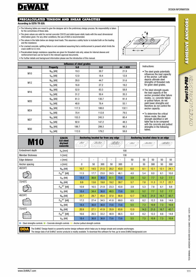
www.DEWALT.com 111
TecH
Man
Ual
– aD
HesI
Ve a
ncHo
Rs ©
2014
DeW
alT
Vol
UMe
1 6/
2014
ADHES
IVE
AN
CHO
RS
DesIGn InfoRMaTIon
PRECALCULATED TENSION AND SHEAR CAPACITIES According to EOTA TR 029.
• The following tables are meant to give the designer aid in the preliminary design process. no responsibility is taken for the correctness of these data.
• The given values are valid for normal concrete c20/25 and static/quasi-static loads with the exact dimensional information given. for any other conditions, the use of DDa is recommended.
• The values in the table below are design level loads. This assumes a safety factor is included both on the loading and the resistance.
• for cracked concrete, splitting failure is not considered assuming that a reinforcement is present which limits the crack width to 0.3 mm.
• Precalculated design resistance capacities are given for threaded rods only, values for internal sleeves and reinforcement bars can be found in the relevant approval documents.
• for further details and background information please see the introduction of this manual.
N
V
F
sh
c
Influence of steel gradesInstructions:
• The steel grade potentially influences the load capacity of the anchor. left table depicts ultimate steel strengths of threaded rods for given steel grades.
• The steel strength equals the load capacity of the anchor provided other failure modes, i.e. concrete failure or pullout failure, do not yield lower strengths and therefore do not control the anchor capacity.
• To determine the critical failure mode, the steel strength identified in left table has to be compared with the concrete and pullout strengths in the following tables.
Size Property 5.8 8.8 A4 / HCR
M10nRd [kn] 19.3 30.7 21.9
VRd [kn] 12.0 18.4 12.8
M12nRd [kn] 28.0 44.7 31.6
VRd [kn] 16.8 27.2 19.2
M16nRd [kn] 52.0 83.3 58.8
VRd [kn] 31.2 50.4 35.3
M20nRd [kn] 81.3 130.7 91.4
VRd [kn] 48.8 78.4 55.1
M24nRd [kn] 117.3 188.0 132.1
VRd [kn] 70.4 112.8 79.5
M27nRd [kn] 153.3 245.3 80.4
VRd [kn] 92.0 147.2 48.3
M30nRd [kn] 186.7 299.3 98.3
VRd [kn] 112.0 179.2 58.8
M10C20/25
8.8 steel dry/wetconcrete
Anchoring located far from any edge Anchoring located close to an edge
embedment depth hef [mm] 100
Member thickness h [mm] 130
edge distance c [mm] - - - - - 50 50 50 50 50
anchor spacing s [mm] 0 50 300 50 300 0 50 300 50 300
40/24˚c nRd [kn] 10.7 14.5 21.5 20.2 43.0 6.0 8.1 12.1 12.1 24.1
fRd45° [kn] 11.5 17.7 23.0 24.5 46.1 4.0 5.4 8.0 6.1 10.0
VRd [kn] 18.4 36.8 36.8 51.1 73.6 3.9 5.2 7.7 5.2 7.7
72/43˚c nRd [kn] 9.9 13.6 19.8 19.2 39.7 5.7 7.8 11.3 11.7 22.7
fRd45° [kn] 10.9 16.5 21.9 23.3 43.8 3.9 5.3 7.8 6.1 9.8
VRd [kn] 18.4 34.4 36.8 48.5 73.6 3.9 5.2 7.7 5.2 7.7
40/24˚c nRd [kn] 22.7 28.7 45.4 37.0 90.8 12.7 14.3 21.0 16.7 42.7
fRd45° [kn] 17.2 27.4 34.5 41.8 69.0 6.5 8.2 12.2 8.6 14.8
VRd [kn] 18.4 36.8 36.8 73.6 73.6 5.5 7.3 10.9 7.3 10.9
72/43˚c nRd [kn] 20.9 27.1 41.9 35.9 83.8 12.0 14.3 21.0 16.7 42.7
fRd45° [kn] 16.6 26.5 33.2 40.9 66.5 6.4 8.2 12.2 8.6 14.8
VRd [kn] 18.4 36.8 36.8 73.6 73.6 5.5 7.3 10.9 7.3 10.9
n - steel strengths controls n - concrete strength controls n - anchor pullout strength controls
DEWALT DESIGN ASSIST
The DeWalT Design assist is a powerful anchor design software which helps you to design simple and complex anchorages.The design data of all DeWalT anchor products is readily available. To download this software for free, go to www.DeWalTdesignassist.com
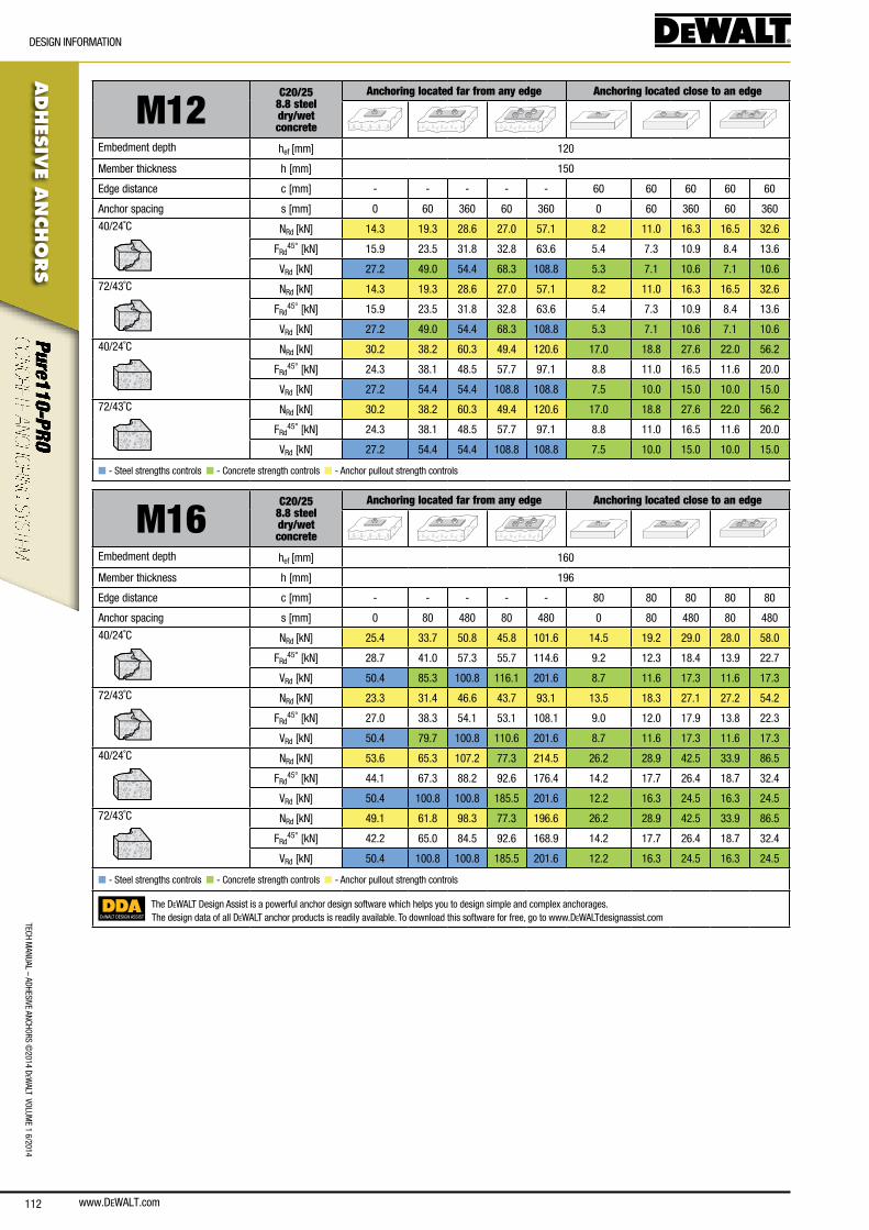
www.DEWALT.com112
TecH ManUal – aDHesIVe ancHoRs ©
2014 DeW
alT VolUMe 1 6/2014
ADHES
IVE A
NCHO
RS
DesIGn InfoRMaTIon
M12C20/25
8.8 steel dry/wetconcrete
Anchoring located far from any edge Anchoring located close to an edge
embedment depth hef [mm] 120
Member thickness h [mm] 150
edge distance c [mm] - - - - - 60 60 60 60 60
anchor spacing s [mm] 0 60 360 60 360 0 60 360 60 360
40/24˚c nRd [kn] 14.3 19.3 28.6 27.0 57.1 8.2 11.0 16.3 16.5 32.6
fRd45° [kn] 15.9 23.5 31.8 32.8 63.6 5.4 7.3 10.9 8.4 13.6
VRd [kn] 27.2 49.0 54.4 68.3 108.8 5.3 7.1 10.6 7.1 10.6
72/43˚c nRd [kn] 14.3 19.3 28.6 27.0 57.1 8.2 11.0 16.3 16.5 32.6
fRd45° [kn] 15.9 23.5 31.8 32.8 63.6 5.4 7.3 10.9 8.4 13.6
VRd [kn] 27.2 49.0 54.4 68.3 108.8 5.3 7.1 10.6 7.1 10.6
40/24˚c nRd [kn] 30.2 38.2 60.3 49.4 120.6 17.0 18.8 27.6 22.0 56.2
fRd45° [kn] 24.3 38.1 48.5 57.7 97.1 8.8 11.0 16.5 11.6 20.0
VRd [kn] 27.2 54.4 54.4 108.8 108.8 7.5 10.0 15.0 10.0 15.0
72/43˚c nRd [kn] 30.2 38.2 60.3 49.4 120.6 17.0 18.8 27.6 22.0 56.2
fRd45° [kn] 24.3 38.1 48.5 57.7 97.1 8.8 11.0 16.5 11.6 20.0
VRd [kn] 27.2 54.4 54.4 108.8 108.8 7.5 10.0 15.0 10.0 15.0
n - steel strengths controls n - concrete strength controls n - anchor pullout strength controls
M16C20/25
8.8 steel dry/wetconcrete
Anchoring located far from any edge Anchoring located close to an edge
embedment depth hef [mm] 160
Member thickness h [mm] 196
edge distance c [mm] - - - - - 80 80 80 80 80
anchor spacing s [mm] 0 80 480 80 480 0 80 480 80 480
40/24˚c nRd [kn] 25.4 33.7 50.8 45.8 101.6 14.5 19.2 29.0 28.0 58.0
fRd45° [kn] 28.7 41.0 57.3 55.7 114.6 9.2 12.3 18.4 13.9 22.7
VRd [kn] 50.4 85.3 100.8 116.1 201.6 8.7 11.6 17.3 11.6 17.3
72/43˚c nRd [kn] 23.3 31.4 46.6 43.7 93.1 13.5 18.3 27.1 27.2 54.2
fRd45° [kn] 27.0 38.3 54.1 53.1 108.1 9.0 12.0 17.9 13.8 22.3
VRd [kn] 50.4 79.7 100.8 110.6 201.6 8.7 11.6 17.3 11.6 17.3
40/24˚c nRd [kn] 53.6 65.3 107.2 77.3 214.5 26.2 28.9 42.5 33.9 86.5
fRd45° [kn] 44.1 67.3 88.2 92.6 176.4 14.2 17.7 26.4 18.7 32.4
VRd [kn] 50.4 100.8 100.8 185.5 201.6 12.2 16.3 24.5 16.3 24.5
72/43˚c nRd [kn] 49.1 61.8 98.3 77.3 196.6 26.2 28.9 42.5 33.9 86.5
fRd45° [kn] 42.2 65.0 84.5 92.6 168.9 14.2 17.7 26.4 18.7 32.4
VRd [kn] 50.4 100.8 100.8 185.5 201.6 12.2 16.3 24.5 16.3 24.5
n - steel strengths controls n - concrete strength controls n - anchor pullout strength controls
DEWALT DESIGN ASSIST
The DeWalT Design assist is a powerful anchor design software which helps you to design simple and complex anchorages.The design data of all DeWalT anchor products is readily available. To download this software for free, go to www.DeWalTdesignassist.com
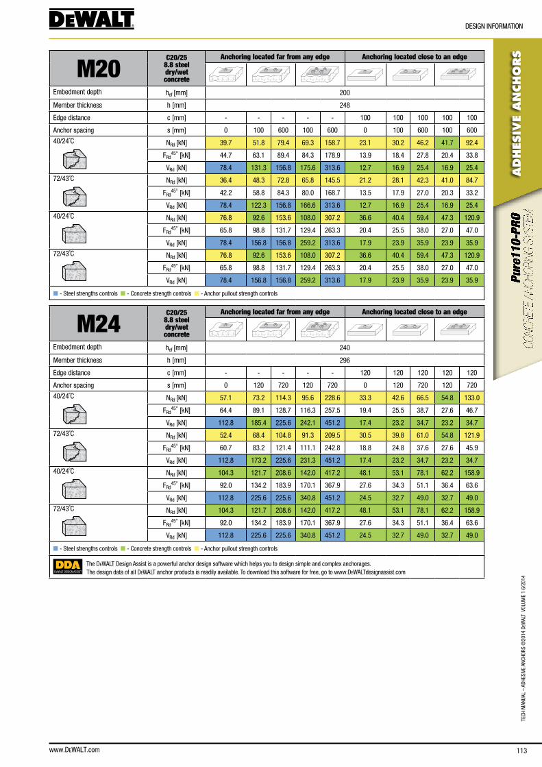
www.DEWALT.com 113
TecH
Man
Ual
– aD
HesI
Ve a
ncHo
Rs ©
2014
DeW
alT
Vol
UMe
1 6/
2014
ADHES
IVE
AN
CHO
RS
DesIGn InfoRMaTIon
M20C20/25
8.8 steel dry/wetconcrete
Anchoring located far from any edge Anchoring located close to an edge
embedment depth hef [mm] 200
Member thickness h [mm] 248
edge distance c [mm] - - - - - 100 100 100 100 100
anchor spacing s [mm] 0 100 600 100 600 0 100 600 100 600
40/24˚c nRd [kn] 39.7 51.8 79.4 69.3 158.7 23.1 30.2 46.2 41.7 92.4
fRd45° [kn] 44.7 63.1 89.4 84.3 178.9 13.9 18.4 27.8 20.4 33.8
VRd [kn] 78.4 131.3 156.8 175.6 313.6 12.7 16.9 25.4 16.9 25.4
72/43˚c nRd [kn] 36.4 48.3 72.8 65.8 145.5 21.2 28.1 42.3 41.0 84.7
fRd45° [kn] 42.2 58.8 84.3 80.0 168.7 13.5 17.9 27.0 20.3 33.2
VRd [kn] 78.4 122.3 156.8 166.6 313.6 12.7 16.9 25.4 16.9 25.4
40/24˚c nRd [kn] 76.8 92.6 153.6 108.0 307.2 36.6 40.4 59.4 47.3 120.9
fRd45° [kn] 65.8 98.8 131.7 129.4 263.3 20.4 25.5 38.0 27.0 47.0
VRd [kn] 78.4 156.8 156.8 259.2 313.6 17.9 23.9 35.9 23.9 35.9
72/43˚c nRd [kn] 76.8 92.6 153.6 108.0 307.2 36.6 40.4 59.4 47.3 120.9
fRd45° [kn] 65.8 98.8 131.7 129.4 263.3 20.4 25.5 38.0 27.0 47.0
VRd [kn] 78.4 156.8 156.8 259.2 313.6 17.9 23.9 35.9 23.9 35.9
n - steel strengths controls n - concrete strength controls n - anchor pullout strength controls
M24C20/25
8.8 steel dry/wetconcrete
Anchoring located far from any edge Anchoring located close to an edge
embedment depth hef [mm] 240
Member thickness h [mm] 296
edge distance c [mm] - - - - - 120 120 120 120 120
anchor spacing s [mm] 0 120 720 120 720 0 120 720 120 720
40/24˚c nRd [kn] 57.1 73.2 114.3 95.6 228.6 33.3 42.6 66.5 54.8 133.0
fRd45° [kn] 64.4 89.1 128.7 116.3 257.5 19.4 25.5 38.7 27.6 46.7
VRd [kn] 112.8 185.4 225.6 242.1 451.2 17.4 23.2 34.7 23.2 34.7
72/43˚c nRd [kn] 52.4 68.4 104.8 91.3 209.5 30.5 39.8 61.0 54.8 121.9
fRd45° [kn] 60.7 83.2 121.4 111.1 242.8 18.8 24.8 37.6 27.6 45.9
VRd [kn] 112.8 173.2 225.6 231.3 451.2 17.4 23.2 34.7 23.2 34.7
40/24˚c nRd [kn] 104.3 121.7 208.6 142.0 417.2 48.1 53.1 78.1 62.2 158.9
fRd45° [kn] 92.0 134.2 183.9 170.1 367.9 27.6 34.3 51.1 36.4 63.6
VRd [kn] 112.8 225.6 225.6 340.8 451.2 24.5 32.7 49.0 32.7 49.0
72/43˚c nRd [kn] 104.3 121.7 208.6 142.0 417.2 48.1 53.1 78.1 62.2 158.9
fRd45° [kn] 92.0 134.2 183.9 170.1 367.9 27.6 34.3 51.1 36.4 63.6
VRd [kn] 112.8 225.6 225.6 340.8 451.2 24.5 32.7 49.0 32.7 49.0
n - steel strengths controls n - concrete strength controls n - anchor pullout strength controls
DEWALT DESIGN ASSIST
The DeWalT Design assist is a powerful anchor design software which helps you to design simple and complex anchorages.The design data of all DeWalT anchor products is readily available. To download this software for free, go to www.DeWalTdesignassist.com
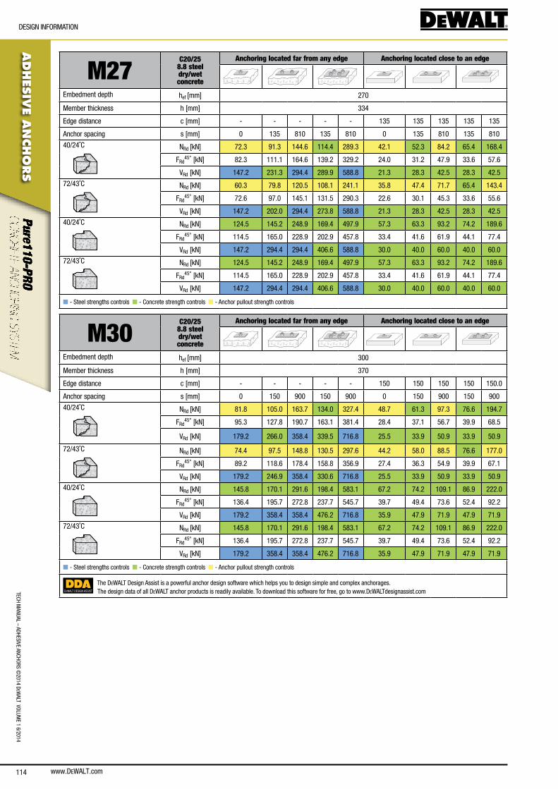
www.DEWALT.com114
TecH ManUal – aDHesIVe ancHoRs ©
2014 DeW
alT VolUMe 1 6/2014
ADHES
IVE A
NCHO
RS
DesIGn InfoRMaTIon
M27C20/25
8.8 steel dry/wetconcrete
Anchoring located far from any edge Anchoring located close to an edge
embedment depth hef [mm] 270
Member thickness h [mm] 334
edge distance c [mm] - - - - - 135 135 135 135 135
anchor spacing s [mm] 0 135 810 135 810 0 135 810 135 810
40/24˚c nRd [kn] 72.3 91.3 144.6 114.4 289.3 42.1 52.3 84.2 65.4 168.4
fRd45° [kn] 82.3 111.1 164.6 139.2 329.2 24.0 31.2 47.9 33.6 57.6
VRd [kn] 147.2 231.3 294.4 289.9 588.8 21.3 28.3 42.5 28.3 42.5
72/43˚c nRd [kn] 60.3 79.8 120.5 108.1 241.1 35.8 47.4 71.7 65.4 143.4
fRd45° [kn] 72.6 97.0 145.1 131.5 290.3 22.6 30.1 45.3 33.6 55.6
VRd [kn] 147.2 202.0 294.4 273.8 588.8 21.3 28.3 42.5 28.3 42.5
40/24˚c nRd [kn] 124.5 145.2 248.9 169.4 497.9 57.3 63.3 93.2 74.2 189.6
fRd45° [kn] 114.5 165.0 228.9 202.9 457.8 33.4 41.6 61.9 44.1 77.4
VRd [kn] 147.2 294.4 294.4 406.6 588.8 30.0 40.0 60.0 40.0 60.0
72/43˚c nRd [kn] 124.5 145.2 248.9 169.4 497.9 57.3 63.3 93.2 74.2 189.6
fRd45° [kn] 114.5 165.0 228.9 202.9 457.8 33.4 41.6 61.9 44.1 77.4
VRd [kn] 147.2 294.4 294.4 406.6 588.8 30.0 40.0 60.0 40.0 60.0
n - steel strengths controls n - concrete strength controls n - anchor pullout strength controls
M30C20/25
8.8 steel dry/wetconcrete
Anchoring located far from any edge Anchoring located close to an edge
embedment depth hef [mm] 300
Member thickness h [mm] 370
edge distance c [mm] - - - - - 150 150 150 150 150.0
anchor spacing s [mm] 0 150 900 150 900 0 150 900 150 900
40/24˚c nRd [kn] 81.8 105.0 163.7 134.0 327.4 48.7 61.3 97.3 76.6 194.7
fRd45° [kn] 95.3 127.8 190.7 163.1 381.4 28.4 37.1 56.7 39.9 68.5
VRd [kn] 179.2 266.0 358.4 339.5 716.8 25.5 33.9 50.9 33.9 50.9
72/43˚c nRd [kn] 74.4 97.5 148.8 130.5 297.6 44.2 58.0 88.5 76.6 177.0
fRd45° [kn] 89.2 118.6 178.4 158.8 356.9 27.4 36.3 54.9 39.9 67.1
VRd [kn] 179.2 246.9 358.4 330.6 716.8 25.5 33.9 50.9 33.9 50.9
40/24˚c nRd [kn] 145.8 170.1 291.6 198.4 583.1 67.2 74.2 109.1 86.9 222.0
fRd45° [kn] 136.4 195.7 272.8 237.7 545.7 39.7 49.4 73.6 52.4 92.2
VRd [kn] 179.2 358.4 358.4 476.2 716.8 35.9 47.9 71.9 47.9 71.9
72/43˚c nRd [kn] 145.8 170.1 291.6 198.4 583.1 67.2 74.2 109.1 86.9 222.0
fRd45° [kn] 136.4 195.7 272.8 237.7 545.7 39.7 49.4 73.6 52.4 92.2
VRd [kn] 179.2 358.4 358.4 476.2 716.8 35.9 47.9 71.9 47.9 71.9
n - steel strengths controls n - concrete strength controls n - anchor pullout strength controls
DEWALT DESIGN ASSIST
The DeWalT Design assist is a powerful anchor design software which helps you to design simple and complex anchorages.The design data of all DeWalT anchor products is readily available. To download this software for free, go to www.DeWalTdesignassist.com
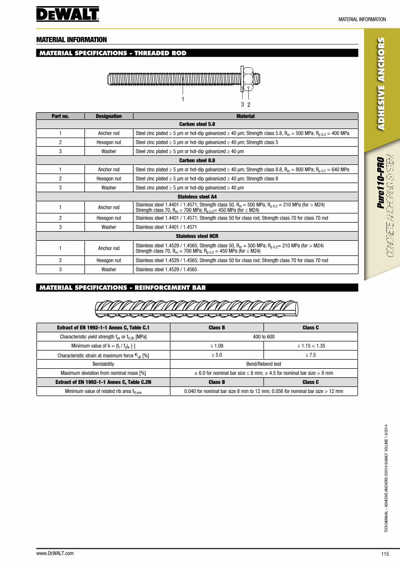
www.DEWALT.com 115
TecH
Man
Ual
– aD
HesI
Ve a
ncHo
Rs ©
2014
DeW
alT
Vol
UMe
1 6/
2014
ADHES
IVE
AN
CHO
RS
MaTeRIal InfoRMaTIon
MATERIAL INFORMATION
MATERIAL SPECIFICATIONS - THREADED ROD
231
Part no. Designation MaterialCarbon steel 5.8
1 anchor rod steel zinc plated ≥ 5 μm or hot-dip galvanized ≥ 40 μm; strength class 5.8, Rm = 500 MPa; Rp 0.2 = 400 MPa
2 Hexagon nut steel zinc plated ≥ 5 μm or hot-dip galvanized ≥ 40 μm; strength class 5
3 Washer steel zinc plated ≥ 5 μm or hot-dip galvanized ≥ 40 μm
Carbon steel 8.8
1 anchor rod steel zinc plated ≥ 5 μm or hot-dip galvanized ≥ 40 μm; strength class 8.8, Rm = 800 MPa; Rp 0.2 = 640 MPa
2 Hexagon nut steel zinc plated ≥ 5 μm or hot-dip galvanized ≥ 40 μm; strength class 8
3 Washer steel zinc plated ≥ 5 μm or hot-dip galvanized ≥ 40 μm
Stainless steel A4
1 anchor rod stainless steel 1.4401 / 1.4571; strength class 50, Rm = 500 MPa; Rp 0.2 = 210 MPa (for > M24)strength class 70, Rm = 700 MPa; Rp 0.2= 450 MPa (for ≤ M24)
2 Hexagon nut stainless steel 1.4401 / 1.4571; strength class 50 for class rod; strength class 70 for class 70 rod
3 Washer stainless steel 1.4401 / 1.4571
Stainless steel HCR
1 anchor rod stainless steel 1.4529 / 1.4565; strength class 50, Rm = 500 MPa; Rp 0.2= 210 MPa (for > M24)strength class 70, Rm = 700 MPa; Rp 0.2 = 450 MPa (for ≤ M24)
2 Hexagon nut stainless steel 1.4529 / 1.4565; strength class 50 for class rod; strength class 70 for class 70 rod
3 Washer stainless steel 1.4529 / 1.4565
MATERIAL SPECIFICATIONS - REINFORCEMENT BAR
Extract of EN 1992-1-1 Annex C, Table C.1 Class B Class C
characteristic yield strength fyk or f0.2k [MPa] 400 to 600
Minimum value of k = (ft / fy)k [-] ≥ 1.08 ≥ 1.15 < 1.35
characteristic strain at maximum force euk [%] ≥ 5.0 ≥ 7.5
bendability bend/Rebend test
Maximum deviation from nominal mass [%] ± 6.0 for nominal bar size ≤ 8 mm; ± 4.5 for nominal bar size > 8 mm
Extract of EN 1992-1-1 Annex C, Table C.2N Class B Class C
Minimum value of related rib area fR,min 0.040 for nominal bar size 8 mm to 12 mm; 0.056 for nominal bar size > 12 mm
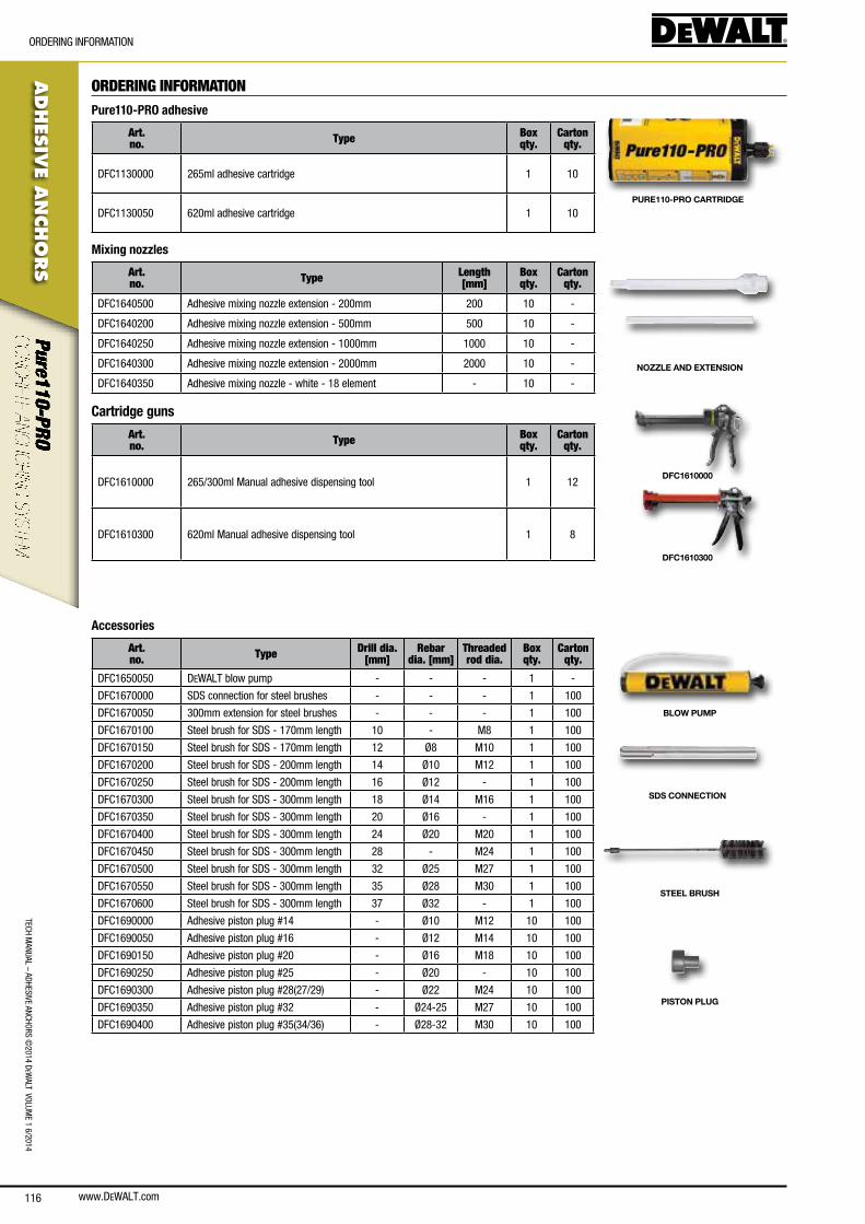
www.DEWALT.com116
TecH ManUal – aDHesIVe ancHoRs ©
2014 DeW
alT VolUMe 1 6/2014
ADHES
IVE A
NCHO
RS
oRDeRInG InfoRMaTIon
ORDERING INFORMATIONPure110-PRO adhesive
Art. no. Type Box
qty.Carton
qty.
Dfc1130000 265ml adhesive cartridge 1 10
Dfc1130050 620ml adhesive cartridge 1 10PURE110-PRO CARTRIDGE
Mixing nozzles
Art. no. Type Length
[mm]Box qty.
Cartonqty.
Dfc1640500 adhesive mixing nozzle extension - 200mm 200 10 -
Dfc1640200 adhesive mixing nozzle extension - 500mm 500 10 -
Dfc1640250 adhesive mixing nozzle extension - 1000mm 1000 10 -
Dfc1640300 adhesive mixing nozzle extension - 2000mm 2000 10 -
Dfc1640350 adhesive mixing nozzle - white - 18 element - 10 -
NOZZLE AND EXTENSION
Cartridge guns
Art. no. Type Box
qty.Carton
qty.
Dfc1610000 265/300ml Manual adhesive dispensing tool 1 12
Dfc1610300 620ml Manual adhesive dispensing tool 1 8
DFC1610000
DFC1610300
Accessories
Art. no. Type Drill dia.
[mm]Rebar
dia. [mm]Threaded rod dia.
Box qty.
Carton qty.
Dfc1650050 DeWalT blow pump - - - 1 -
Dfc1670000 sDs connection for steel brushes - - - 1 100
Dfc1670050 300mm extension for steel brushes - - - 1 100
Dfc1670100 steel brush for sDs - 170mm length 10 - M8 1 100
Dfc1670150 steel brush for sDs - 170mm length 12 Ø8 M10 1 100
Dfc1670200 steel brush for sDs - 200mm length 14 Ø10 M12 1 100
Dfc1670250 steel brush for sDs - 200mm length 16 Ø12 - 1 100
Dfc1670300 steel brush for sDs - 300mm length 18 Ø14 M16 1 100
Dfc1670350 steel brush for sDs - 300mm length 20 Ø16 - 1 100
Dfc1670400 steel brush for sDs - 300mm length 24 Ø20 M20 1 100
Dfc1670450 steel brush for sDs - 300mm length 28 - M24 1 100
Dfc1670500 steel brush for sDs - 300mm length 32 Ø25 M27 1 100
Dfc1670550 steel brush for sDs - 300mm length 35 Ø28 M30 1 100
Dfc1670600 steel brush for sDs - 300mm length 37 Ø32 - 1 100
Dfc1690000 adhesive piston plug #14 - Ø10 M12 10 100
Dfc1690050 adhesive piston plug #16 - Ø12 M14 10 100
Dfc1690150 adhesive piston plug #20 - Ø16 M18 10 100
Dfc1690250 adhesive piston plug #25 - Ø20 - 10 100
Dfc1690300 adhesive piston plug #28(27/29) - Ø22 M24 10 100
Dfc1690350 adhesive piston plug #32 - Ø24-25 M27 10 100
Dfc1690400 adhesive piston plug #35(34/36) - Ø28-32 M30 10 100
BLOW PUMP
SDS CONNECTION
STEEL BRUSH
PISTON PLUG
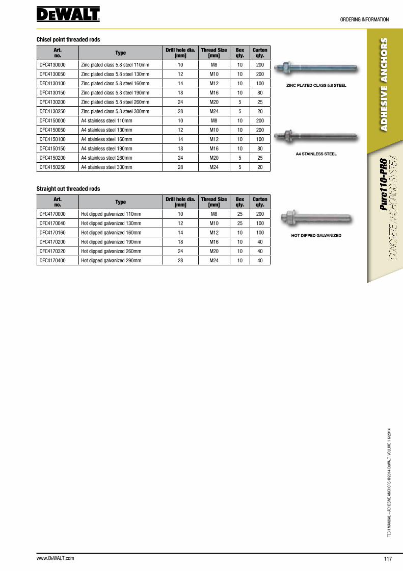
www.DEWALT.com 117
TecH
Man
Ual
– aD
HesI
Ve a
ncHo
Rs ©
2014
DeW
alT
Vol
UMe
1 6/
2014
ADHES
IVE
AN
CHO
RS
oRDeRInG InfoRMaTIon
Chisel point threaded rods
Art. no. Type Drill hole dia.
[mm]Thread Size
[mm]Box qty.
Carton qty.
Dfc4130000 Zinc plated class 5.8 steel 110mm 10 M8 10 200
Dfc4130050 Zinc plated class 5.8 steel 130mm 12 M10 10 200
Dfc4130100 Zinc plated class 5.8 steel 160mm 14 M12 10 100
Dfc4130150 Zinc plated class 5.8 steel 190mm 18 M16 10 80
Dfc4130200 Zinc plated class 5.8 steel 260mm 24 M20 5 25
Dfc4130250 Zinc plated class 5.8 steel 300mm 28 M24 5 20
Dfc4150000 a4 stainless steel 110mm 10 M8 10 200
Dfc4150050 a4 stainless steel 130mm 12 M10 10 200
Dfc4150100 a4 stainless steel 160mm 14 M12 10 100
Dfc4150150 a4 stainless steel 190mm 18 M16 10 80
Dfc4150200 a4 stainless steel 260mm 24 M20 5 25
Dfc4150250 a4 stainless steel 300mm 28 M24 5 20
Straight cut threaded rods
Art. no. Type Drill hole dia.
[mm]Thread Size
[mm]Box qty.
Carton qty.
Dfc4170000 Hot dipped galvanized 110mm 10 M8 25 200
Dfc4170040 Hot dipped galvanized 130mm 12 M10 25 100
Dfc4170160 Hot dipped galvanized 160mm 14 M12 10 100
Dfc4170200 Hot dipped galvanized 190mm 18 M16 10 40
Dfc4170320 Hot dipped galvanized 260mm 24 M20 10 40
Dfc4170400 Hot dipped galvanized 290mm 28 M24 10 40
ZINC PLATED CLASS 5.8 STEEL
A4 STAINLESS STEEL
HOT DIPPED GALVANIZED
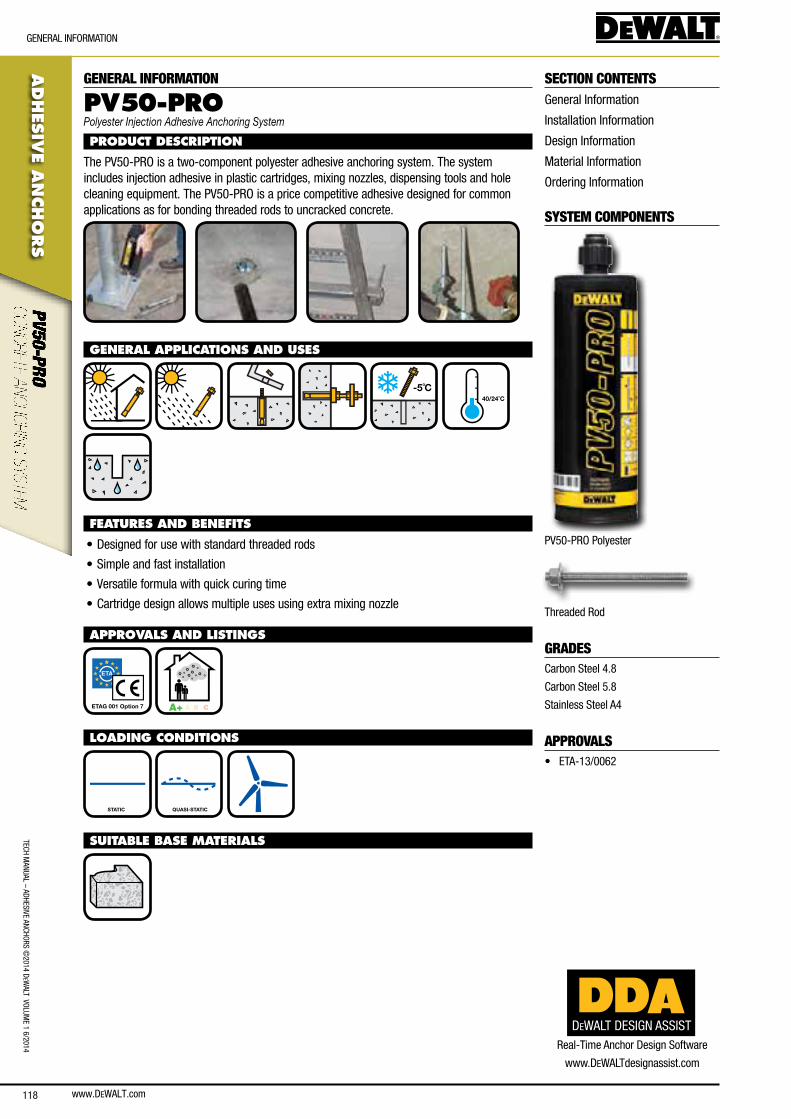
www.DEWALT.com118
TecH ManUal – aDHesIVe ancHoRs ©
2014 DeW
alT VolUMe 1 6/2014
ADHES
IVE A
NCHO
RS
GeneRal InfoRMaTIon
GENERAL INFORMATION
PV5 0-PROPolyester Injection Adhesive Anchoring System
PRODUCT DESCRIPTION
The PV50-PRo is a two-component polyester adhesive anchoring system. The system includes injection adhesive in plastic cartridges, mixing nozzles, dispensing tools and hole cleaning equipment. The PV50-PRo is a price competitive adhesive designed for common applications as for bonding threaded rods to uncracked concrete.
GENERAL APPLICATIONS AND USES
-5˚C
40/24˚C
FEATURES AND BENEFITS
• Designed for use with standard threaded rods
• simple and fast installation
• Versatile formula with quick curing time
• cartridge design allows multiple uses using extra mixing nozzle
APPROVALS AND LISTINGS
ETAG 001 Option 7 A+ A B C
LOADING CONDITIONS
STATIC QUASI-STATIC
SUITABLE BASE MATERIALS
SECTION CONTENTSGeneral Information
Installation Information
Design Information
Material Information
ordering Information
SYSTEM COMPONENTS
PV50-PRo Polyester
Threaded Rod
GRADEScarbon steel 4.8
carbon steel 5.8
stainless steel a4
APPROVALS• eTa-13/0062
DEWALT DESIGN ASSISTReal-Time anchor Design software
www.DeWalTdesignassist.com
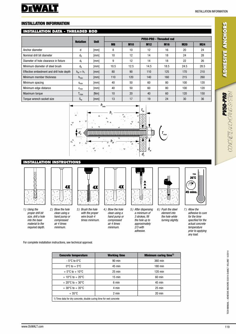
www.DEWALT.com 119
TecH
Man
Ual
– aD
HesI
Ve a
ncHo
Rs ©
2014
DeW
alT
Vol
UMe
1 6/
2014
ADHES
IVE
AN
CHO
RS
InsTallaTIon InfoRMaTIon
INSTALLATION INFORMATION
INSTALLATION DATA - THREADED ROD
Notation UnitPV50-PRO - Threaded rod
M8 M10 M12 M16 M20 M24
anchor diameter d [mm] 8 10 12 16 20 24
nominal drill bit diameter d0 [mm] 10 12 14 18 24 28
Diameter of hole clearance in fixture df [mm] 9 12 14 18 22 26
Minimum diameter of steel brush db [mm] 10.5 12.5 14.5 18.5 24.5 28.5
effective embedment and drill hole depth hef = h1 [mm] 80 90 110 125 170 210
Minimum member thickness hmin [mm] 110 120 140 160 215 260
Minimum spacing smin [mm] 40 50 60 80 100 120
Minimum edge distance cmin [mm] 40 50 60 80 100 120
Maximum torque Tmax [nm] 10 20 40 60 120 150
Torque wrench socket size sw [mm] 13 17 19 24 30 36
hmin
h1
hef
d0
Sw
Tmax
df
tfix
INSTALLATION INSTRUCTIONS
4X 4X 4X
e.g.
20˚C
45 mins.
1.) Using the proper drill bit size, drill a hole into the base material to the required depth.
2.) Blow the hole clean using a hand pump or compressed air 4 times minimum.
3.) Brush the hole with the proper wire brush 4 times minimum.
4.) Blow the hole clean using a hand pump or compressed air 4 times minimum.
5.) After dispensing a minimum of 3 strokes, fill the hole up to approximately 2/3 with adhesive.
6.) Push the steel element into the hole while turning slightly.
7.) Allow the adhesive to cure for the time specified for the actual concrete temperature prior to applying any load.
for complete installation instructions, see technical approval.
Concrete temperature Working time Minimum curing time1)
- 5°c to 0°c 90 min 360 min
0°c to + 5°c 45 min 180 min
+ 5°c to + 10°c 25 min 120 min
+ 10°c to + 20°c 15 min 60 min
+ 20°c to + 30°c 6 min 45 min
+ 30°c to + 35°c 4 min 25 min
+ 35°c 2 min 20 min
1) Time data for dry concrete, double curing time for wet concrete
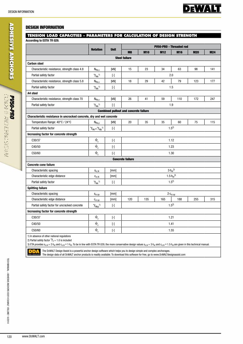
www.DEWALT.com120
ADHES
IVE A
NCHO
RS
DesIGn InfoRMaTIon
TecH ManUal – aDHesIVe ancHoRs ©
2014 DeW
alT VolUMe 1 6/2014
DESIGN INFORMATION
TENSION LOAD CAPACITIES - PARAMETERS FOR CALCULATION OF DESIGN STRENGTHAccording to EOTA TR 029.
Notation UnitPV50-PRO - Threaded rod
M8 M10 M12 M16 M20 M24
Steel failure
Carbon steel
characteristic resistance, strength class 4.8 nRk,s [kn] 15 23 34 63 98 141
Partial safety factor gMs
1) [-] 2.0
characteristic resistance, strength class 5.8 nRk,s [kn] 18 29 42 79 123 177
Partial safety factor gMs
1) [-] 1.5
A4 steel
characteristic resistance, strength class 70 nRk,s [kn] 26 41 59 110 172 247
Partial safety factor gMs
1) [-] 1.9
Combined pullout and concrete failure
Characteristic resistance in uncracked concrete, dry and wet concrete
Temperature Range: 40°c / 24°c nRk,p [kn] 20 35 35 60 75 115
Partial safety factor gMc=g
Mp1) [-] 1.52)
Increasing factor for concrete strength
c30/37 cc [-] 1.12
c40/50 cc [-] 1.23
c50/60 cc [-] 1.30
Concrete failure
Concrete cone failure
characteristic spacing scr,n [mm] 3·hef3)
characteristic edge distance ccr,n [mm] 1.5·hef3)
Partial safety factor gMc
1) [-] 1.52)
Splitting failure
characteristic spacing scr,sp [mm] 2·ccr,sp
characteristic edge distance ccr,sp [mm] 120 135 165 188 255 315
Partial safety factor for uncracked concrete gMsp
1) [-] 1.52)
Increasing factor for concrete strength
c30/37 cc [-] 1.21
c40/50 cc [-] 1.41
c50/60 cc [-] 1.55
1) In absence of other national regulations
2) Partial safety factor g2 = 1.0 is included
3) eTa provides scr,n = 2·hef and ccr,n = 1·hef. To be in line with eoTa TR 029, the more conservative design values scr,n = 3·hef and ccr,n = 1.5·hef are given in this technical manual.
DEWALT DESIGN ASSIST
The DeWalT Design assist is a powerful anchor design software which helps you to design simple and complex anchorages.The design data of all DeWalT anchor products is readily available. To download this software for free, go to www.DeWalTdesignassist.com
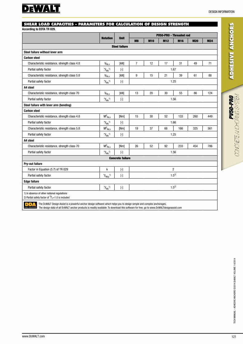
www.DEWALT.com 121
TecH
Man
Ual
– aD
HesI
Ve a
ncHo
Rs ©
2014
DeW
alT
Vol
UMe
1 6/
2014
ADHES
IVE
AN
CHO
RS
DesIGn InfoRMaTIon
SHEAR LOAD CAPACITIES - PARAMETERS FOR CALCULATION OF DESIGN STRENGTHAccording to EOTA TR 029.
Notation UnitPV50-PRO - Threaded rod
M8 M10 M12 M16 M20 M24
Steel failure
Steel failure without lever arm
Carbon steel
characteristic resistance, strength class 4.8 VRk,s [kn] 7 12 17 31 49 71
Partial safety factor gMs
1) [-] 1.67
characteristic resistance, strength class 5.8 VRk,s [kn] 9 15 21 39 61 88
Partial safety factor gMs
1) [-] 1.25
A4 steel
characteristic resistance, strength class 70 VRk,s [kn] 13 20 30 55 86 124
Partial safety factor gMs
1) [-] 1.56
Steel failure with lever arm (bending)
Carbon steel
characteristic resistance, strength class 4.8 M0Rk,s [nm] 15 30 52 133 260 449
Partial safety factor gMs
1) [-] 1.66
characteristic resistance, strength class 5.8 M0Rk,s [nm] 19 37 66 166 325 561
Partial safety factor gMs
1) [-] 1.25
A4 steel
characteristic resistance, strength class 70 M0Rk,s [nm] 26 52 92 233 454 786
Partial safety factor gMs
1) [-] 1.56
Concrete failure
Pry-out failure
factor in equation (5.7) of TR 029 k [-] 2
Partial safety factor gMcp
1) [-] 1.52)
Edge failure
Partial safety factor gMc
1) [-] 1.52)
1) In absence of other national regulations
2) Partial safety factor of g2=1.0 is included
DEWALT DESIGN ASSIST
The DeWalT Design assist is a powerful anchor design software which helps you to design simple and complex anchorages.The design data of all DeWalT anchor products is readily available. To download this software for free, go to www.DeWalTdesignassist.com
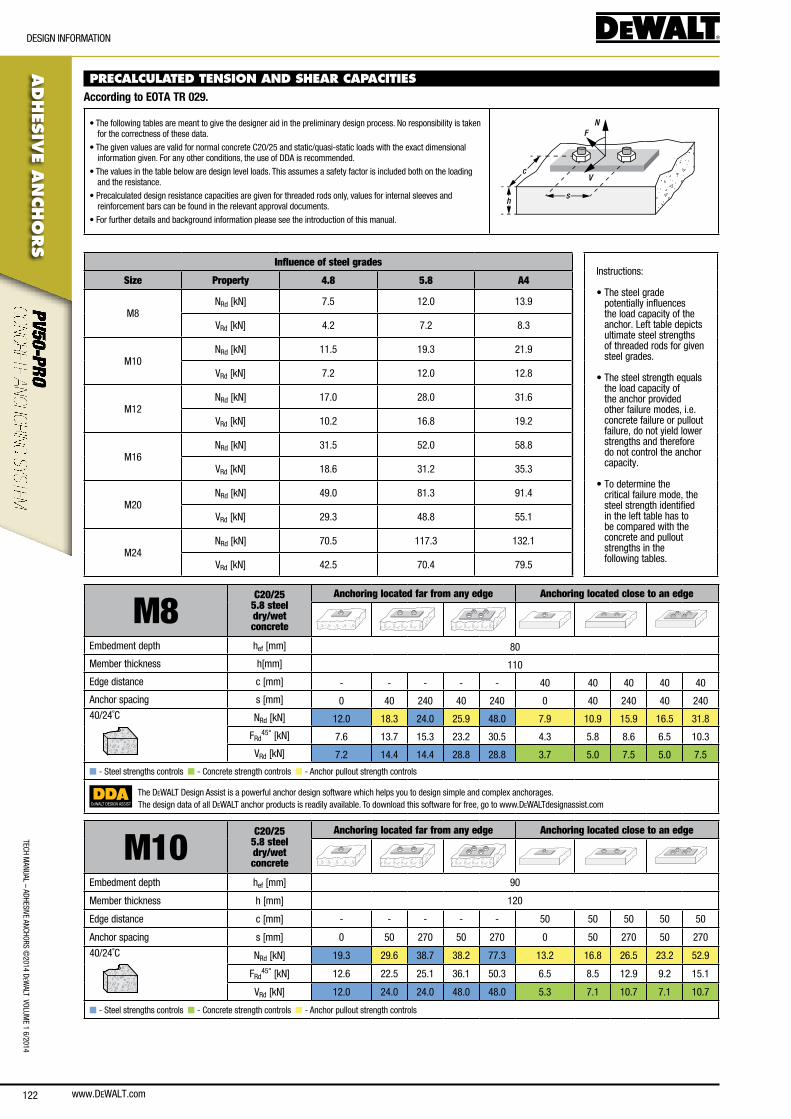
www.DEWALT.com122
TecH ManUal – aDHesIVe ancHoRs ©
2014 DeW
alT VolUMe 1 6/2014
ADHES
IVE A
NCHO
RS
DesIGn InfoRMaTIon
PRECALCULATED TENSION AND SHEAR CAPACITIES According to EOTA TR 029.
• The following tables are meant to give the designer aid in the preliminary design process. no responsibility is taken for the correctness of these data.
• The given values are valid for normal concrete c20/25 and static/quasi-static loads with the exact dimensional information given. for any other conditions, the use of DDa is recommended.
• The values in the table below are design level loads. This assumes a safety factor is included both on the loading and the resistance.
• Precalculated design resistance capacities are given for threaded rods only, values for internal sleeves and reinforcement bars can be found in the relevant approval documents.
• for further details and background information please see the introduction of this manual.
N
V
F
sh
c
Influence of steel gradesInstructions:
• The steel grade potentially influences the load capacity of the anchor. left table depicts ultimate steel strengths of threaded rods for given steel grades.
• The steel strength equals the load capacity of the anchor provided other failure modes, i.e. concrete failure or pullout failure, do not yield lower strengths and therefore do not control the anchor capacity.
• To determine the critical failure mode, the steel strength identified in the left table has to be compared with the concrete and pullout strengths in the following tables.
Size Property 4.8 5.8 A4
M8nRd [kn] 7.5 12.0 13.9
VRd [kn] 4.2 7.2 8.3
M10nRd [kn] 11.5 19.3 21.9
VRd [kn] 7.2 12.0 12.8
M12nRd [kn] 17.0 28.0 31.6
VRd [kn] 10.2 16.8 19.2
M16nRd [kn] 31.5 52.0 58.8
VRd [kn] 18.6 31.2 35.3
M20nRd [kn] 49.0 81.3 91.4
VRd [kn] 29.3 48.8 55.1
M24nRd [kn] 70.5 117.3 132.1
VRd [kn] 42.5 70.4 79.5
M8C20/25
5.8 steel dry/wetconcrete
Anchoring located far from any edge Anchoring located close to an edge
embedment depth hef [mm] 80
Member thickness h[mm] 110
edge distance c [mm] - - - - - 40 40 40 40 40
anchor spacing s [mm] 0 40 240 40 240 0 40 240 40 24040/24˚c nRd [kn] 12.0 18.3 24.0 25.9 48.0 7.9 10.9 15.9 16.5 31.8
fRd45° [kn] 7.6 13.7 15.3 23.2 30.5 4.3 5.8 8.6 6.5 10.3
VRd [kn] 7.2 14.4 14.4 28.8 28.8 3.7 5.0 7.5 5.0 7.5
n - steel strengths controls n - concrete strength controls n - anchor pullout strength controls
DEWALT DESIGN ASSIST
The DeWalT Design assist is a powerful anchor design software which helps you to design simple and complex anchorages.The design data of all DeWalT anchor products is readily available. To download this software for free, go to www.DeWalTdesignassist.com
M10C20/25
5.8 steel dry/wetconcrete
Anchoring located far from any edge Anchoring located close to an edge
embedment depth hef [mm] 90
Member thickness h [mm] 120
edge distance c [mm] - - - - - 50 50 50 50 50
anchor spacing s [mm] 0 50 270 50 270 0 50 270 50 270
40/24˚c nRd [kn] 19.3 29.6 38.7 38.2 77.3 13.2 16.8 26.5 23.2 52.9
fRd45° [kn] 12.6 22.5 25.1 36.1 50.3 6.5 8.5 12.9 9.2 15.1
VRd [kn] 12.0 24.0 24.0 48.0 48.0 5.3 7.1 10.7 7.1 10.7
n - steel strengths controls n - concrete strength controls n - anchor pullout strength controls
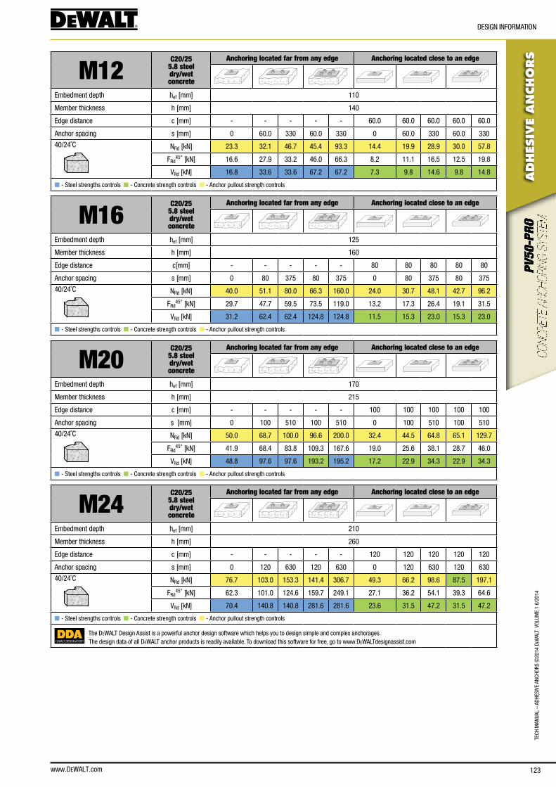
www.DEWALT.com 123
TecH
Man
Ual
– aD
HesI
Ve a
ncHo
Rs ©
2014
DeW
alT
Vol
UMe
1 6/
2014
ADHES
IVE
AN
CHO
RS
DesIGn InfoRMaTIon
M12C20/25
5.8 steel dry/wetconcrete
Anchoring located far from any edge Anchoring located close to an edge
embedment depth hef [mm] 110
Member thickness h [mm] 140
edge distance c [mm] - - - - - 60.0 60.0 60.0 60.0 60.0
anchor spacing s [mm] 0 60.0 330 60.0 330 0 60.0 330 60.0 330
40/24˚c nRd [kn] 23.3 32.1 46.7 45.4 93.3 14.4 19.9 28.9 30.0 57.8
fRd45° [kn] 16.6 27.9 33.2 46.0 66.3 8.2 11.1 16.5 12.5 19.8
VRd [kn] 16.8 33.6 33.6 67.2 67.2 7.3 9.8 14.6 9.8 14.8
n - steel strengths controls n - concrete strength controls n - anchor pullout strength controls
M16C20/25
5.8 steel dry/wetconcrete
Anchoring located far from any edge Anchoring located close to an edge
embedment depth hef [mm] 125
Member thickness h [mm] 160
edge distance c[mm] - - - - - 80 80 80 80 80
anchor spacing s [mm] 0 80 375 80 375 0 80 375 80 375
40/24˚c nRd [kn] 40.0 51.1 80.0 66.3 160.0 24.0 30.7 48.1 42.7 96.2
fRd45° [kn] 29.7 47.7 59.5 73.5 119.0 13.2 17.3 26.4 19.1 31.5
VRd [kn] 31.2 62.4 62.4 124.8 124.8 11.5 15.3 23.0 15.3 23.0
n - steel strengths controls n - concrete strength controls n - anchor pullout strength controls
M20C20/25
5.8 steel dry/wetconcrete
Anchoring located far from any edge Anchoring located close to an edge
embedment depth hef [mm] 170
Member thickness h [mm] 215
edge distance c [mm] - - - - - 100 100 100 100 100
anchor spacing s [mm] 0 100 510 100 510 0 100 510 100 510
40/24˚c nRd [kn] 50.0 68.7 100.0 96.6 200.0 32.4 44.5 64.8 65.1 129.7
fRd45° [kn] 41.9 68.4 83.8 109.3 167.6 19.0 25.6 38.1 28.7 46.0
VRd [kn] 48.8 97.6 97.6 193.2 195.2 17.2 22.9 34.3 22.9 34.3
n - steel strengths controls n - concrete strength controls n - anchor pullout strength controls
M24C20/25
5.8 steel dry/wetconcrete
Anchoring located far from any edge Anchoring located close to an edge
embedment depth hef [mm] 210
Member thickness h [mm] 260
edge distance c [mm] - - - - - 120 120 120 120 120
anchor spacing s [mm] 0 120 630 120 630 0 120 630 120 630
40/24˚c nRd [kn] 76.7 103.0 153.3 141.4 306.7 49.3 66.2 98.6 87.5 197.1
fRd45° [kn] 62.3 101.0 124.6 159.7 249.1 27.1 36.2 54.1 39.3 64.6
VRd [kn] 70.4 140.8 140.8 281.6 281.6 23.6 31.5 47.2 31.5 47.2
n - steel strengths controls n - concrete strength controls n - anchor pullout strength controls
DEWALT DESIGN ASSIST
The DeWalT Design assist is a powerful anchor design software which helps you to design simple and complex anchorages.The design data of all DeWalT anchor products is readily available. To download this software for free, go to www.DeWalTdesignassist.com
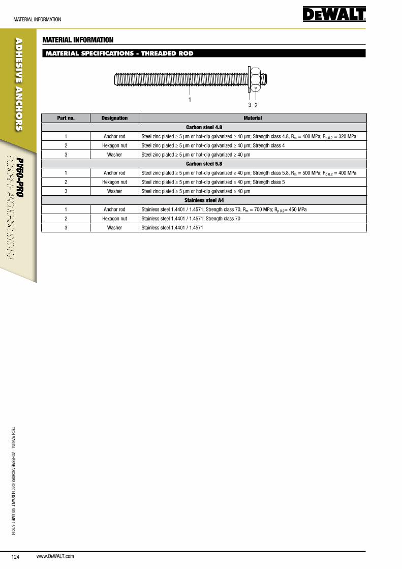
www.DEWALT.com124
TecH ManUal – aDHesIVe ancHoRs ©
2014 DeW
alT VolUMe 1 6/2014
ADHES
IVE A
NCHO
RS
MaTeRIal InfoRMaTIon
MATERIAL INFORMATION
MATERIAL SPECIFICATIONS - THREADED ROD
231
Part no. Designation Material
Carbon steel 4.8
1 anchor rod steel zinc plated ≥ 5 μm or hot-dip galvanized ≥ 40 μm; strength class 4.8, Rm = 400 MPa; Rp 0.2 = 320 MPa
2 Hexagon nut steel zinc plated ≥ 5 μm or hot-dip galvanized ≥ 40 μm; strength class 4
3 Washer steel zinc plated ≥ 5 μm or hot-dip galvanized ≥ 40 μm
Carbon steel 5.8
1 anchor rod steel zinc plated ≥ 5 μm or hot-dip galvanized ≥ 40 μm; strength class 5.8, Rm = 500 MPa; Rp 0.2 = 400 MPa
2 Hexagon nut steel zinc plated ≥ 5 μm or hot-dip galvanized ≥ 40 μm; strength class 5
3 Washer steel zinc plated ≥ 5 μm or hot-dip galvanized ≥ 40 μm
Stainless steel A4
1 anchor rod stainless steel 1.4401 / 1.4571; strength class 70, Rm = 700 MPa; Rp 0.2= 450 MPa
2 Hexagon nut stainless steel 1.4401 / 1.4571; strength class 70
3 Washer stainless steel 1.4401 / 1.4571

www.DEWALT.com 125
TecH
Man
Ual
– aD
HesI
Ve a
ncHo
Rs ©
2014
DeW
alT
Vol
UMe
1 6/
2014
ADHES
IVE
AN
CHO
RS
oRDeRInG InfoRMaTIon
ORDERING INFORMATIONPV50-PRO adhesive
Art. no. Type Box
qty.Carton
qty.
Dfc1310000 300ml cartridge 1 10
Dfc1310150 360ml cartridge 1 10
Dfc1310100 410ml cartridge 1 10
PV50-PRO CARTRIDGE
Mixing nozzles
Art. no. Type Length
[mm]Box qty.
Carton qty.
Dfc1640500 adhesive mixing nozzle extension - 200mm 200 10 -
Dfc1640200 adhesive mixing nozzle extension - 500mm 500 10 -
Dfc1640250 adhesive mixing nozzle extension - 1000mm 1000 10 -
Dfc1640300 adhesive mixing nozzle extension - 2000mm 2000 10 -
Dfc1640450 adhesive mixing nozzle - black - 14 element - 10 -
ADHESIVE MIXING NOZZLE EXTENSION
ADHESIVE MIXING NOZZLE - BLACK
Cartridge guns
Art. no. Type Box
qty.Carton
Qty.
Dfc1610000 300ml Manual adhesive dispensing tool 1 12
Dfc1610050 345 / 360ml Manual adhesive dispensing tool 1 10
Dfc1610100 410ml Manual adhesive dispensing tool 1 10
Dfc1610150 410ml Heavy duty manual adhesive dispensing tool 1 10
Dfc1630250 410ml Pneumatic adhesive dispensing tool 1 -
DFC1610000
DFC1610100
DFC1610150
Accessories
Art. no. Type Drill dia.
[mm]Rebar
dia. [mm]Threaded rod dia.
Box qty.
Carton qty.
Dfc1650050 DeWalT blow pump - - - 1 -
Dfc1670000 sDs connection for steel brushes - - - 1 100
Dfc1670050 300mm extension for steel brushes - - - 1 100
Dfc1670100 steel brush for sDs - 170mm length 10 - M8 1 100
Dfc1670150 steel brush for sDs - 170mm length 12 Ø8 M10 1 100
Dfc1670200 steel brush for sDs - 200mm length 14 Ø10 M12 1 100
Dfc1670250 steel brush for sDs - 200mm length 16 Ø12 - 1 100
Dfc1670300 steel brush for sDs - 300mm length 18 Ø14 M16 1 100
Dfc1670350 steel brush for sDs - 300mm length 20 Ø16 - 1 100
Dfc1670400 steel brush for sDs - 300mm length 24 Ø20 M20 1 100
Dfc1670450 steel brush for sDs - 300mm length 28 - M24 1 100
Dfc1670500 steel brush for sDs - 300mm length 32 Ø25 M27 1 100
Dfc1670550 steel brush for sDs - 300mm length 35 Ø28 M30 1 100
Dfc1670600 steel brush for sDs - 300mm length 37 Ø32 - 1 100
BLOW PUMP
SDS CONNECTION
STEEL BRUSH

www.DEWALT.com126
TecH ManUal – aDHesIVe ancHoRs ©
2014 DeW
alT VolUMe 1 6/2014
ADHES
IVE A
NCHO
RS
oRDeRInG InfoRMaTIon
Chisel point threaded rods
Art. no. Type Drill hole dia.
[mm]Thread Size
[mm]Box qty.
Carton qty.
Dfc4130000 Zinc plated class 5.8 steel 110mm 10 M8 10 200
Dfc4130050 Zinc plated class 5.8 steel 130mm 12 M10 10 200
Dfc4130100 Zinc plated class 5.8 steel 160mm 14 M12 10 100
Dfc4130150 Zinc plated class 5.8 steel 190mm 18 M16 10 80
Dfc4130200 Zinc plated class 5.8 steel 260mm 24 M20 5 25
Dfc4130250 Zinc plated class 5.8 steel 300mm 28 M24 5 20
Dfc4150000 a4 stainless steel 110mm 10 M8 10 200
Dfc4150050 a4 stainless steel 130mm 12 M10 10 200
Dfc4150100 a4 stainless steel 160mm 14 M12 10 100
Dfc4150150 a4 stainless steel 190mm 18 M16 10 80
Dfc4150200 a4 stainless steel 260mm 24 M20 5 25
Dfc4150250 a4 stainless steel 300mm 28 M24 5 20
Straight cut threaded rods
Art. no. Type Drill hole dia.
[mm]Thread Size
[mm]Box qty.
Carton qty.
Dfc4170000 Hot dipped galvanized 110mm 10 M8 25 200
Dfc4170040 Hot dipped galvanized 130mm 12 M10 25 100
Dfc4170160 Hot dipped galvanized 160mm 14 M12 10 100
Dfc4170200 Hot dipped galvanized 190mm 18 M16 10 40
Dfc4170320 Hot dipped galvanized 260mm 24 M20 10 40
Dfc4170400 Hot dipped galvanized 290mm 28 M24 10 40
ZINC PLATED CLASS 5.8 STEEL
A4 STAINLESS STEEL
HOT DIPPED GALVANIZED
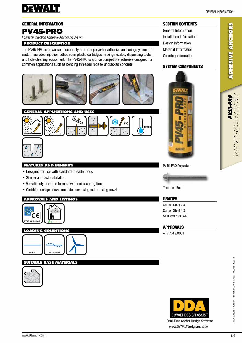
www.DEWALT.com 127
TecH
Man
Ual
– aD
HesI
Ve a
ncHo
Rs ©
2014
DeW
alT
Vol
UMe
1 6/
2014
ADHES
IVE
AN
CHO
RS
GeneRal InfoRMaTIon
SECTION CONTENTSGeneral Information
Installation Information
Design Information
Material Information
ordering Information
SYSTEM COMPONENTS
PV45-PRo Polyester
Threaded Rod
GRADEScarbon steel 4.8
carbon steel 5.8
stainless steel a4
APPROVALS• eTa-13/0061
GENERAL INFORMATION
PV45-PROPolyester Injection Adhesive Anchoring System
PRODUCT DESCRIPTION
The PV45-PRo is a two-component styrene-free polyester adhesive anchoring system. The system includes injection adhesive in plastic cartridges, mixing nozzles, dispensing tools and hole cleaning equipment. The PV45-PRo is a price competitive adhesive designed for common applications such as bonding threaded rods to uncracked concrete.
GENERAL APPLICATIONS AND USES
-5˚C
40/24˚C
FEATURES AND BENEFITS
• Designed for use with standard threaded rods
• simple and fast installation
• Versatile styrene-free formula with quick curing time
• cartridge design allows multiple uses using extra mixing nozzle
APPROVALS AND LISTINGS
ETAG 001 Option 7 A+ A B C
LOADING CONDITIONS
STATIC QUASI-STATIC
SUITABLE BASE MATERIALS
DEWALT DESIGN ASSISTReal-Time anchor Design software
www.DeWalTdesignassist.com
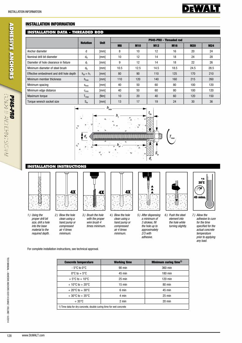
www.DEWALT.com128
TecH ManUal – aDHesIVe ancHoRs ©
2014 DeW
alT VolUMe 1 6/2014
ADHES
IVE A
NCHO
RS
InsTallaTIon InfoRMaTIon
INSTALLATION INFORMATION
INSTALLATION DATA - THREADED ROD
Notation UnitPV45-PRO - Threaded rod
M8 M10 M12 M16 M20 M24
anchor diameter d [mm] 8 10 12 16 20 24
nominal drill bit diameter d0 [mm] 10 12 14 18 24 28
Diameter of hole clearance in fixture df [mm] 9 12 14 18 22 26
Minimum diameter of steel brush db [mm] 10.5 12.5 14.5 18.5 24.5 28.5
effective embedment and drill hole depth hef = h1 [mm] 80 90 110 125 170 210
Minimum member thickness hmin [mm] 110 120 140 160 215 260
Minimum spacing smin [mm] 40 50 60 80 100 120
Minimum edge distance cmin [mm] 40 50 60 80 100 120
Maximum torque Tmax [nm] 10 20 40 60 120 150
Torque wrench socket size sw [mm] 13 17 19 24 30 36
hmin
h1
hef
d0
Sw
Tmax
df
tfix
INSTALLATION INSTRUCTIONS
4X 4X 4X
e.g.
20˚C
45 mins.
1.) Using the proper drill bit size, drill a hole into the base material to the required depth.
2.) Blow the hole clean using a hand pump or compressed air 4 times minimum.
3.) Brush the hole with the proper wire brush 4 times minimum.
4.) Blow the hole clean using a hand pump or compressed air 4 times minimum.
5.) After dispensing a minimum of 3 strokes, fill the hole up to approximately 2/3 with adhesive.
6.) Push the steel element into the hole while turning slightly.
7.) Allow the adhesive to cure for the time specified for the actual concrete temperature prior to applying any load.
for complete installation instructions, see technical approval.
Concrete temperature Working time Minimum curing time1)
- 5°c to 0°c 90 min 360 min
0°c to + 5°c 45 min 180 min
+ 5°c to + 10°c 25 min 120 min
+ 10°c to + 20°c 15 min 80 min
+ 20°c to + 30°c 6 min 45 min
+ 30°c to + 35°c 4 min 25 min
+ 35°c 2 min 20 min
1) Time data for dry concrete, double curing time for wet concrete
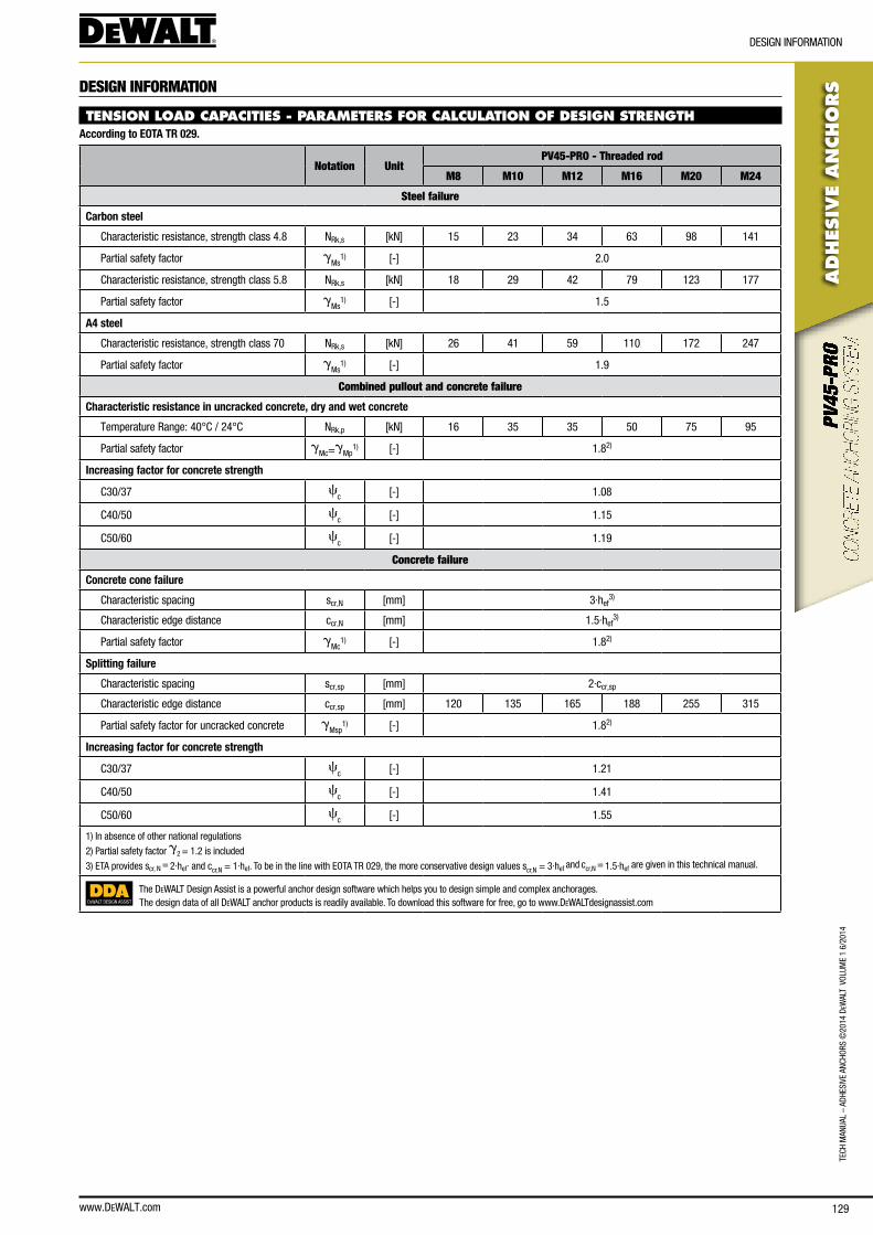
www.DEWALT.com 129
TecH
Man
Ual
– aD
HesI
Ve a
ncHo
Rs ©
2014
DeW
alT
Vol
UMe
1 6/
2014
ADHES
IVE
AN
CHO
RS
DesIGn InfoRMaTIon
DESIGN INFORMATION
TENSION LOAD CAPACITIES - PARAMETERS FOR CALCULATION OF DESIGN STRENGTHAccording to EOTA TR 029.
Notation UnitPV45-PRO - Threaded rod
M8 M10 M12 M16 M20 M24
Steel failure
Carbon steel
characteristic resistance, strength class 4.8 nRk,s [kn] 15 23 34 63 98 141
Partial safety factor gMs
1) [-] 2.0
characteristic resistance, strength class 5.8 nRk,s [kn] 18 29 42 79 123 177
Partial safety factor gMs
1) [-] 1.5
A4 steel
characteristic resistance, strength class 70 nRk,s [kn] 26 41 59 110 172 247
Partial safety factor gMs
1) [-] 1.9
Combined pullout and concrete failure
Characteristic resistance in uncracked concrete, dry and wet concrete
Temperature Range: 40°c / 24°c nRk,p [kn] 16 35 35 50 75 95
Partial safety factor gMc=g
Mp1) [-] 1.82)
Increasing factor for concrete strength
c30/37 cc [-] 1.08
c40/50 cc [-] 1.15
c50/60 cc [-] 1.19
Concrete failure
Concrete cone failure
characteristic spacing scr,n [mm] 3·hef3)
characteristic edge distance ccr,n [mm] 1.5·hef3)
Partial safety factor gMc
1) [-] 1.82)
Splitting failure
characteristic spacing scr,sp [mm] 2·ccr,sp
characteristic edge distance ccr,sp [mm] 120 135 165 188 255 315
Partial safety factor for uncracked concrete gMsp
1) [-] 1.82)
Increasing factor for concrete strength
c30/37 cc [-] 1.21
c40/50 cc [-] 1.41
c50/60 cc [-] 1.55
1) In absence of other national regulations
2) Partial safety factor g2 = 1.2 is included
3) eTa provides scr, n = 2·hef· and ccr,n = 1·hef. To be in the line with eoTa TR 029, the more conservative design values scr,n = 3·hef and ccr,n = 1.5·hef are given in this technical manual.
DEWALT DESIGN ASSIST
The DeWalT Design assist is a powerful anchor design software which helps you to design simple and complex anchorages.The design data of all DeWalT anchor products is readily available. To download this software for free, go to www.DeWalTdesignassist.com
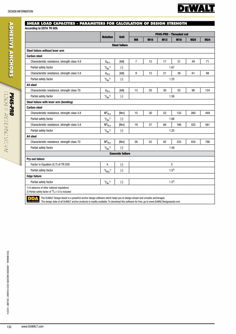
www.DEWALT.com130
ADHES
IVE A
NCHO
RS
DesIGn InfoRMaTIon
TecH ManUal – aDHesIVe ancHoRs ©
2014 DeW
alT VolUMe 1 6/2014
SHEAR LOAD CAPACITIES - PARAMETERS FOR CALCULATION OF DESIGN STRENGTHAccording to EOTA TR 029.
Notation UnitPV45-PRO - Threaded rod
M8 M10 M12 M16 M20 M24
Steel failure
Steel failure without lever arm
Carbon steel
characteristic resistance, strength class 4.8 VRk,s [kn] 7 12 17 31 49 71
Partial safety factor gMs
1) [-] 1.67
characteristic resistance, strength class 5.8 VRk,s [kn] 9 15 21 39 61 88
Partial safety factor gMs
1) [-] 1.25
A4 steel
characteristic resistance, strength class 70 VRk,s [kn] 13 20 30 55 86 124
Partial safety factor gMs
1) [-] 1.56
Steel failure with lever arm (bending)
Carbon steel
characteristic resistance, strength class 4.8 M0Rk,s [nm] 15 30 52 133 260 449
Partial safety factor gMs
1) [-] 1.66
characteristic resistance, strength class 5.8 M0Rk,s [nm] 19 37 66 166 325 561
Partial safety factor gMs
1) [-] 1.25
A4 steel
characteristic resistance, strength class 70 M0Rk,s [nm] 26 52 92 233 454 786
Partial safety factor gMs
1) [-] 1.56
Concrete failure
Pry-out failure
factor in equation (5.7) of TR 029 k [-] 2
Partial safety factor gMcp
1) [-] 1.52)
Edge failure
Partial safety factor gMc
1) [-] 1.52)
1) In absence of other national regulations
2) Partial safety factor of g2=1.0 is included
DEWALT DESIGN ASSIST
The DeWalT Design assist is a powerful anchor design software which helps you to design simple and complex anchorages.The design data of all DeWalT anchor products is readily available. To download this software for free, go to www.DeWalTdesignassist.com
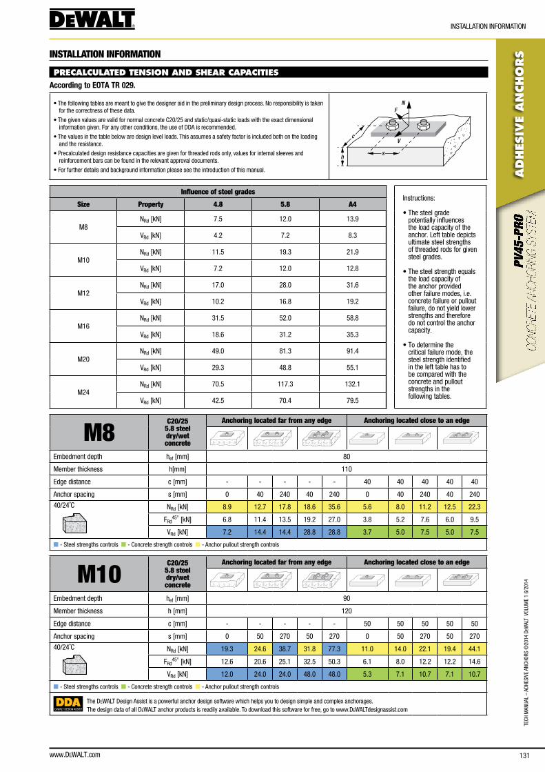
www.DEWALT.com 131
TecH
Man
Ual
– aD
HesI
Ve a
ncHo
Rs ©
2014
DeW
alT
Vol
UMe
1 6/
2014
ADHES
IVE
AN
CHO
RS
InsTallaTIon InfoRMaTIon
INSTALLATION INFORMATION
PRECALCULATED TENSION AND SHEAR CAPACITIES According to EOTA TR 029.
• The following tables are meant to give the designer aid in the preliminary design process. no responsibility is taken for the correctness of these data.
• The given values are valid for normal concrete c20/25 and static/quasi-static loads with the exact dimensional information given. for any other conditions, the use of DDa is recommended.
• The values in the table below are design level loads. This assumes a safety factor is included both on the loading and the resistance.
• Precalculated design resistance capacities are given for threaded rods only, values for internal sleeves and reinforcement bars can be found in the relevant approval documents.
• for further details and background information please see the introduction of this manual.
N
V
F
sh
c
Influence of steel gradesInstructions:
• The steel grade potentially influences the load capacity of the anchor. left table depicts ultimate steel strengths of threaded rods for given steel grades.
• The steel strength equals the load capacity of the anchor provided other failure modes, i.e. concrete failure or pullout failure, do not yield lower strengths and therefore do not control the anchor capacity.
• To determine the critical failure mode, the steel strength identified in the left table has to be compared with the concrete and pullout strengths in the following tables.
Size Property 4.8 5.8 A4
M8nRd [kn] 7.5 12.0 13.9
VRd [kn] 4.2 7.2 8.3
M10nRd [kn] 11.5 19.3 21.9
VRd [kn] 7.2 12.0 12.8
M12nRd [kn] 17.0 28.0 31.6
VRd [kn] 10.2 16.8 19.2
M16nRd [kn] 31.5 52.0 58.8
VRd [kn] 18.6 31.2 35.3
M20nRd [kn] 49.0 81.3 91.4
VRd [kn] 29.3 48.8 55.1
M24nRd [kn] 70.5 117.3 132.1
VRd [kn] 42.5 70.4 79.5
M8C20/25
5.8 steel dry/wetconcrete
Anchoring located far from any edge Anchoring located close to an edge
embedment depth hef [mm] 80
Member thickness h[mm] 110
edge distance c [mm] - - - - - 40 40 40 40 40
anchor spacing s [mm] 0 40 240 40 240 0 40 240 40 240
40/24˚c nRd [kn] 8.9 12.7 17.8 18.6 35.6 5.6 8.0 11.2 12.5 22.3
fRd45° [kn] 6.8 11.4 13.5 19.2 27.0 3.8 5.2 7.6 6.0 9.5
VRd [kn] 7.2 14.4 14.4 28.8 28.8 3.7 5.0 7.5 5.0 7.5
n - steel strengths controls n - concrete strength controls n - anchor pullout strength controls
M10C20/25
5.8 steel dry/wetconcrete
Anchoring located far from any edge Anchoring located close to an edge
embedment depth hef [mm] 90
Member thickness h [mm] 120
edge distance c [mm] - - - - - 50 50 50 50 50
anchor spacing s [mm] 0 50 270 50 270 0 50 270 50 270
40/24˚c nRd [kn] 19.3 24.6 38.7 31.8 77.3 11.0 14.0 22.1 19.4 44.1
fRd45° [kn] 12.6 20.6 25.1 32.5 50.3 6.1 8.0 12.2 12.2 14.6
VRd [kn] 12.0 24.0 24.0 48.0 48.0 5.3 7.1 10.7 7.1 10.7
n - steel strengths controls n - concrete strength controls n - anchor pullout strength controls
DEWALT DESIGN ASSIST
The DeWalT Design assist is a powerful anchor design software which helps you to design simple and complex anchorages.The design data of all DeWalT anchor products is readily available. To download this software for free, go to www.DeWalTdesignassist.com
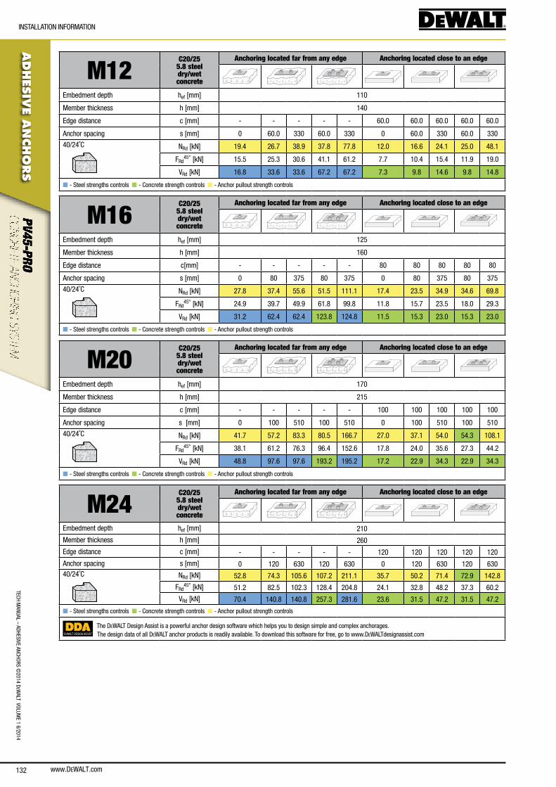
www.DEWALT.com132
TecH ManUal – aDHesIVe ancHoRs ©
2014 DeW
alT VolUMe 1 6/2014
ADHES
IVE A
NCHO
RS
InsTallaTIon InfoRMaTIon
M12C20/25
5.8 steel dry/wetconcrete
Anchoring located far from any edge Anchoring located close to an edge
embedment depth hef [mm] 110
Member thickness h [mm] 140
edge distance c [mm] - - - - - 60.0 60.0 60.0 60.0 60.0
anchor spacing s [mm] 0 60.0 330 60.0 330 0 60.0 330 60.0 330
40/24˚c nRd [kn] 19.4 26.7 38.9 37.8 77.8 12.0 16.6 24.1 25.0 48.1
fRd45° [kn] 15.5 25.3 30.6 41.1 61.2 7.7 10.4 15.4 11.9 19.0
VRd [kn] 16.8 33.6 33.6 67.2 67.2 7.3 9.8 14.6 9.8 14.8
n - steel strengths controls n - concrete strength controls n - anchor pullout strength controls
M16C20/25
5.8 steel dry/wetconcrete
Anchoring located far from any edge Anchoring located close to an edge
embedment depth hef [mm] 125
Member thickness h [mm] 160
edge distance c[mm] - - - - - 80 80 80 80 80
anchor spacing s [mm] 0 80 375 80 375 0 80 375 80 375
40/24˚c nRd [kn] 27.8 37.4 55.6 51.5 111.1 17.4 23.5 34.9 34.6 69.8
fRd45° [kn] 24.9 39.7 49.9 61.8 99.8 11.8 15.7 23.5 18.0 29.3
VRd [kn] 31.2 62.4 62.4 123.8 124.8 11.5 15.3 23.0 15.3 23.0
n - steel strengths controls n - concrete strength controls n - anchor pullout strength controls
M20C20/25
5.8 steel dry/wetconcrete
Anchoring located far from any edge Anchoring located close to an edge
embedment depth hef [mm] 170
Member thickness h [mm] 215
edge distance c [mm] - - - - - 100 100 100 100 100
anchor spacing s [mm] 0 100 510 100 510 0 100 510 100 510
40/24˚c nRd [kn] 41.7 57.2 83.3 80.5 166.7 27.0 37.1 54.0 54.3 108.1
fRd45° [kn] 38.1 61.2 76.3 96.4 152.6 17.8 24.0 35.6 27.3 44.2
VRd [kn] 48.8 97.6 97.6 193.2 195.2 17.2 22.9 34.3 22.9 34.3
n - steel strengths controls n - concrete strength controls n - anchor pullout strength controls
M24C20/25
5.8 steel dry/wetconcrete
Anchoring located far from any edge Anchoring located close to an edge
embedment depth hef [mm] 210
Member thickness h [mm] 260
edge distance c [mm] - - - - - 120 120 120 120 120
anchor spacing s [mm] 0 120 630 120 630 0 120 630 120 63040/24˚c nRd [kn] 52.8 74.3 105.6 107.2 211.1 35.7 50.2 71.4 72.9 142.8
fRd45° [kn] 51.2 82.5 102.3 128.4 204.8 24.1 32.8 48.2 37.3 60.2
VRd [kn] 70.4 140.8 140.8 257.3 281.6 23.6 31.5 47.2 31.5 47.2
n - steel strengths controls n - concrete strength controls n - anchor pullout strength controls
DEWALT DESIGN ASSIST
The DeWalT Design assist is a powerful anchor design software which helps you to design simple and complex anchorages.The design data of all DeWalT anchor products is readily available. To download this software for free, go to www.DeWalTdesignassist.com
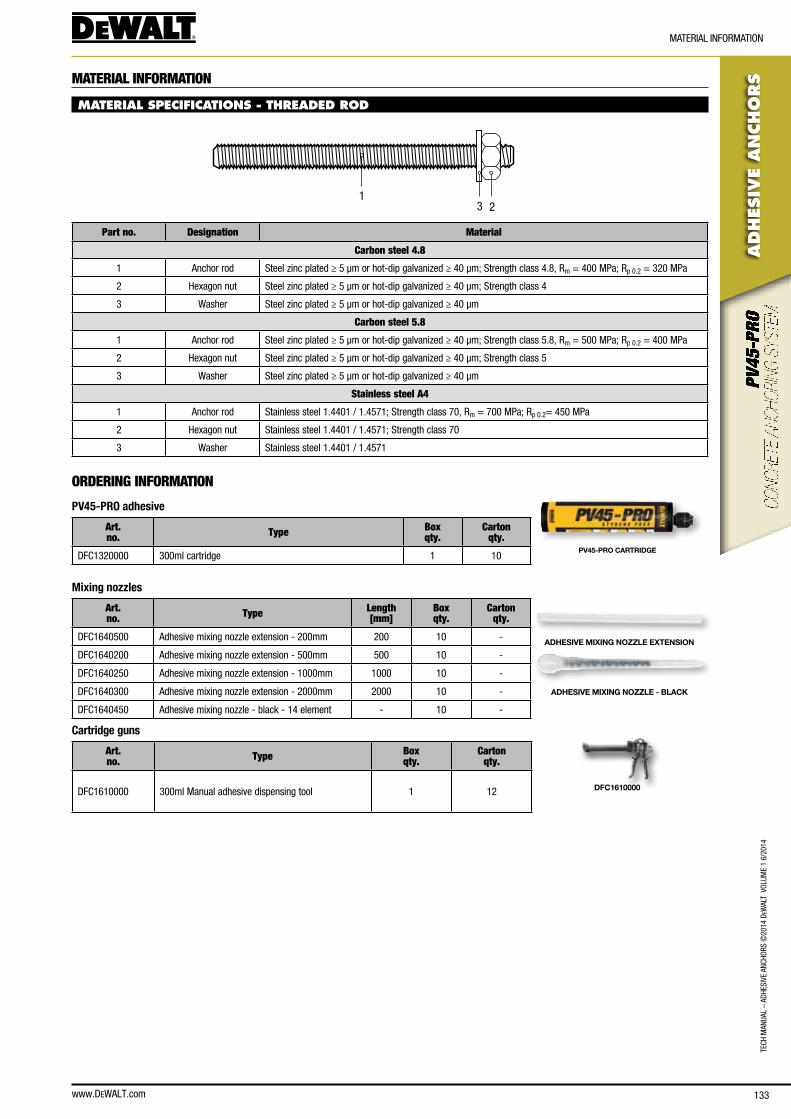
www.DEWALT.com 133
TecH
Man
Ual
– aD
HesI
Ve a
ncHo
Rs ©
2014
DeW
alT
Vol
UMe
1 6/
2014
ADHES
IVE
AN
CHO
RS
MaTeRIal InfoRMaTIon
MATERIAL INFORMATION
MATERIAL SPECIFICATIONS - THREADED ROD
231
Part no. Designation Material
Carbon steel 4.8
1 anchor rod steel zinc plated ≥ 5 μm or hot-dip galvanized ≥ 40 μm; strength class 4.8, Rm = 400 MPa; Rp 0.2 = 320 MPa
2 Hexagon nut steel zinc plated ≥ 5 μm or hot-dip galvanized ≥ 40 μm; strength class 4
3 Washer steel zinc plated ≥ 5 μm or hot-dip galvanized ≥ 40 μm
Carbon steel 5.8
1 anchor rod steel zinc plated ≥ 5 μm or hot-dip galvanized ≥ 40 μm; strength class 5.8, Rm = 500 MPa; Rp 0.2 = 400 MPa
2 Hexagon nut steel zinc plated ≥ 5 μm or hot-dip galvanized ≥ 40 μm; strength class 5
3 Washer steel zinc plated ≥ 5 μm or hot-dip galvanized ≥ 40 μm
Stainless steel A4
1 anchor rod stainless steel 1.4401 / 1.4571; strength class 70, Rm = 700 MPa; Rp 0.2= 450 MPa
2 Hexagon nut stainless steel 1.4401 / 1.4571; strength class 70
3 Washer stainless steel 1.4401 / 1.4571
ORDERING INFORMATION
PV45-PRO adhesive
Art. no. Type Box
qty.Carton
qty.
Dfc1320000 300ml cartridge 1 10PV45-PRO CARTRIDGE
Mixing nozzles
Art. no. Type Length
[mm]Box qty.
Carton qty.
Dfc1640500 adhesive mixing nozzle extension - 200mm 200 10 -
Dfc1640200 adhesive mixing nozzle extension - 500mm 500 10 -
Dfc1640250 adhesive mixing nozzle extension - 1000mm 1000 10 -
Dfc1640300 adhesive mixing nozzle extension - 2000mm 2000 10 -
Dfc1640450 adhesive mixing nozzle - black - 14 element - 10 -
ADHESIVE MIXING NOZZLE EXTENSION
ADHESIVE MIXING NOZZLE - BLACK
Cartridge guns
Art. no. Type Box
qty.Carton
qty.
Dfc1610000 300ml Manual adhesive dispensing tool 1 12 DFC1610000
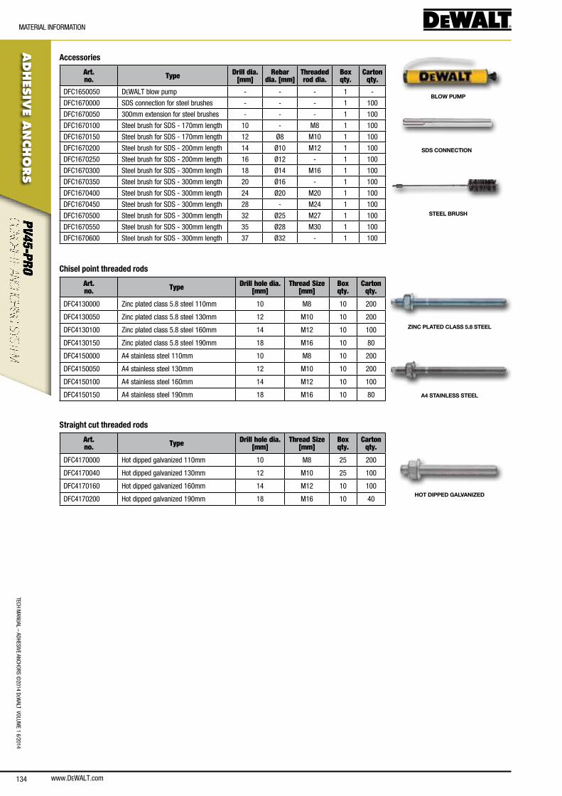
www.DEWALT.com134
TecH ManUal – aDHesIVe ancHoRs ©
2014 DeW
alT VolUMe 1 6/2014
ADHES
IVE A
NCHO
RS
MaTeRIal InfoRMaTIon
Accessories
Art. no. Type Drill dia.
[mm]Rebar
dia. [mm]Threaded rod dia.
Box qty.
Carton qty.
Dfc1650050 DeWalT blow pump - - - 1 -
Dfc1670000 sDs connection for steel brushes - - - 1 100
Dfc1670050 300mm extension for steel brushes - - - 1 100
Dfc1670100 steel brush for sDs - 170mm length 10 - M8 1 100
Dfc1670150 steel brush for sDs - 170mm length 12 Ø8 M10 1 100
Dfc1670200 steel brush for sDs - 200mm length 14 Ø10 M12 1 100
Dfc1670250 steel brush for sDs - 200mm length 16 Ø12 - 1 100
Dfc1670300 steel brush for sDs - 300mm length 18 Ø14 M16 1 100
Dfc1670350 steel brush for sDs - 300mm length 20 Ø16 - 1 100
Dfc1670400 steel brush for sDs - 300mm length 24 Ø20 M20 1 100
Dfc1670450 steel brush for sDs - 300mm length 28 - M24 1 100
Dfc1670500 steel brush for sDs - 300mm length 32 Ø25 M27 1 100
Dfc1670550 steel brush for sDs - 300mm length 35 Ø28 M30 1 100
Dfc1670600 steel brush for sDs - 300mm length 37 Ø32 - 1 100
BLOW PUMP
SDS CONNECTION
STEEL BRUSH
Chisel point threaded rods
Art. no. Type Drill hole dia.
[mm]Thread Size
[mm]Box qty.
Carton qty.
Dfc4130000 Zinc plated class 5.8 steel 110mm 10 M8 10 200
Dfc4130050 Zinc plated class 5.8 steel 130mm 12 M10 10 200
Dfc4130100 Zinc plated class 5.8 steel 160mm 14 M12 10 100
Dfc4130150 Zinc plated class 5.8 steel 190mm 18 M16 10 80
Dfc4150000 a4 stainless steel 110mm 10 M8 10 200
Dfc4150050 a4 stainless steel 130mm 12 M10 10 200
Dfc4150100 a4 stainless steel 160mm 14 M12 10 100
Dfc4150150 a4 stainless steel 190mm 18 M16 10 80
Straight cut threaded rods
Art. no. Type Drill hole dia.
[mm]Thread Size
[mm]Box qty.
Carton qty.
Dfc4170000 Hot dipped galvanized 110mm 10 M8 25 200
Dfc4170040 Hot dipped galvanized 130mm 12 M10 25 100
Dfc4170160 Hot dipped galvanized 160mm 14 M12 10 100
Dfc4170200 Hot dipped galvanized 190mm 18 M16 10 40
ZINC PLATED CLASS 5.8 STEEL
A4 STAINLESS STEEL
HOT DIPPED GALVANIZED
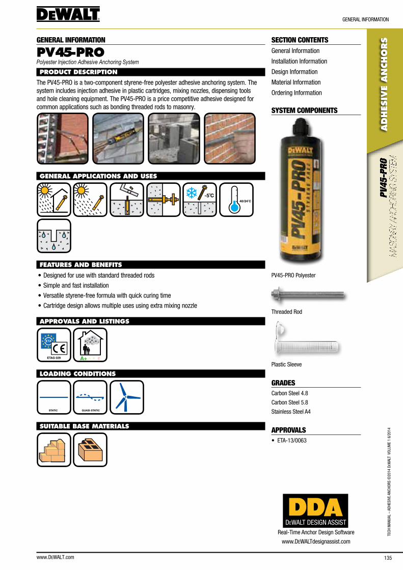
www.DEWALT.com 135
TecH
Man
Ual
– aD
HesI
Ve a
ncHo
Rs ©
2014
DeW
alT
Vol
UMe
1 6/
2014
ADHES
IVE
AN
CHO
RS
GeneRal InfoRMaTIon
SECTION CONTENTSGeneral Information
Installation Information
Design Information
Material Information
ordering Information
SYSTEM COMPONENTS
PV45-PRo Polyester
Threaded Rod
Plastic sleeve
GRADEScarbon steel 4.8
carbon steel 5.8
stainless steel a4
APPROVALS• eTa-13/0063
GENERAL INFORMATION
PV45-PROPolyester Injection Adhesive Anchoring System
PRODUCT DESCRIPTION
The PV45-PRo is a two-component styrene-free polyester adhesive anchoring system. The system includes injection adhesive in plastic cartridges, mixing nozzles, dispensing tools and hole cleaning equipment. The PV45-PRo is a price competitive adhesive designed for common applications such as bonding threaded rods to masonry.
GENERAL APPLICATIONS AND USES
-5˚C
40/24˚C
FEATURES AND BENEFITS
• Designed for use with standard threaded rods
• simple and fast installation
• Versatile styrene-free formula with quick curing time
• cartridge design allows multiple uses using extra mixing nozzle
APPROVALS AND LISTINGS
ETAG 029 A+ A B C
LOADING CONDITIONS
STATIC QUASI-STATIC
SUITABLE BASE MATERIALS
DEWALT DESIGN ASSISTReal-Time anchor Design software
www.DeWalTdesignassist.com

www.DEWALT.com136
TecH ManUal – aDHesIVe ancHoRs ©
2014 DeW
alT VolUMe 1 6/2014
ADHES
IVE A
NCHO
RS
InsTallaTIon InfoRMaTIon
INSTALLATION INFORMATION
INSTALLATION DATA - THREADED ROD
Notation UnitPV45-PRO - Solid bricks, without sleeve
M8 M10 M12 M16
anchor diameter d [mm] 8 10 12 16
nominal drill bit diameter d0 [mm] 10 12 14 18
Diameter of hole clearance in fixture df [mm] ≤ 9 ≤ 11 ≤ 13 ≤ 17
Minimum diameter of nylon brush db [mm] ≥ 11 ≥ 14 ≥ 16 ≥ 18
embedment depth hef [mm] 80 90 100 100
bore hole depth h1 [mm] 80 90 100 100
Minimum spacing for solid bricks smin [mm] 50 50 50 54
Minimum edge distance for solid bricks cmin [mm] 50 50 50 54
Maximum torque Tmax [nm] 2 2 2 2
Torque wrench socket size sw [mm] 13 17 19 24
h1
hef
d0
Sw
Tmax
df
tfix
INSTALLATION DATA - SOLID AND HOLLOW BRICKS, WITH SLEEVE
Notation UnitSolid and hollow bricks, with sleeve
M8 M10 M12
sleeve type sH 12x80 sH 16x85 sH 20x185
anchor diameter d [mm] 8 8 10
nominal drill bit diameter d0 [mm] 12 16 20
Diameter of hole clearance in fixture df [mm] ≤ 9 ≤ 11 ≤ 13
Diameter of nylon brush db [mm] ≥ 14 ≥ 18 ≥ 22
embedment depth hef [mm] 80 85 85
embedment depth sleeve ℓs [mm] 80 85 85
bore hole depth h1 [mm] 85 90 90
Minimum spacing for solid bricks smin [mm] 50 50 50
Minimum spacing for hollow bricks smin [mm] 100 100 120
Minimum edge distance for solid bricks cmin [mm] 50 50 50
Minimum edge distance for hollow brick cmin [mm] 100 100 120
Maximum torque Tmax [nm] 2 2 2
Torque wrench socket size sw [mm] 13 17 19
h1
hef
d0
Sw
Tmax
df
tfix
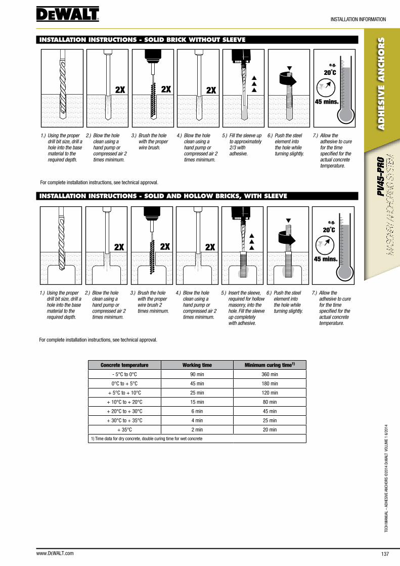
www.DEWALT.com 137
TecH
Man
Ual
– aD
HesI
Ve a
ncHo
Rs ©
2014
DeW
alT
Vol
UMe
1 6/
2014
ADHES
IVE
AN
CHO
RS
InsTallaTIon InfoRMaTIon
INSTALLATION INSTRUCTIONS - SOLID BRICK WITHOUT SLEEVE
2X 2X 2X
e.g.
20˚C
45 mins.
1.) Using the proper drill bit size, drill a hole into the base material to the required depth.
2.) Blow the hole clean using a hand pump or compressed air 2 times minimum.
3.) Brush the hole with the proper wire brush.
4.) Blow the hole clean using a hand pump or compressed air 2 times minimum.
5.) Fill the sleeve up to approximately 2/3 with adhesive.
6.) Push the steel element into the hole while turning slightly.
7.) Allow the adhesive to cure for the time specified for the actual concrete temperature.
for complete installation instructions, see technical approval.
INSTALLATION INSTRUCTIONS - SOLID AND HOLLOW BRICKS, WITH SLEEVE
2X 2X 2X
e.g.
20˚C
45 mins.
1.) Using the proper drill bit size, drill a hole into the base material to the required depth.
2.) Blow the hole clean using a hand pump or compressed air 2 times minimum.
3.) Brush the hole with the proper wire brush 2 times minimum.
4.) Blow the hole clean using a hand pump or compressed air 2 times minimum.
5.) Insert the sleeve, required for hollow masonry, into the hole. Fill the sleeve up completely with adhesive.
6.) Push the steel element into the hole while turning slightly.
7.) Allow the adhesive to cure for the time specified for the actual concrete temperature.
for complete installation instructions, see technical approval.
Concrete temperature Working time Minimum curing time1)
- 5°c to 0°c 90 min 360 min
0°c to + 5°c 45 min 180 min
+ 5°c to + 10°c 25 min 120 min
+ 10°c to + 20°c 15 min 80 min
+ 20°c to + 30°c 6 min 45 min
+ 30°c to + 35°c 4 min 25 min
+ 35°c 2 min 20 min
1) Time data for dry concrete, double curing time for wet concrete
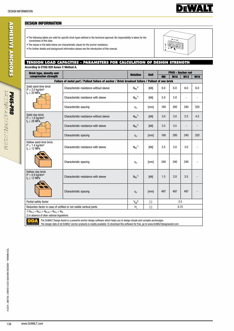
www.DEWALT.com138
ADHES
IVE A
NCHO
RS
DesIGn InfoRMaTIon
TecH ManUal – aDHesIVe ancHoRs ©
2014 DeW
alT VolUMe 1 6/2014
DESIGN INFORMATION
• The following tables are valid for specific brick types defined in the technical approval. no responsibility is taken for the correctness of this data.
• The values in the table below are characteristic values for the anchor resistance.
• for further details and background information please see the introduction of this manual. NV
s
c
TENSION LOAD CAPACITIES - PARAMETERS FOR CALCULATION OF DESIGN STRENGTHAccording to ETAG 029 Annex C Method A.
Brick type, density and compressive strength Notation Unit
PV45 - Anchor rodM8 M10 M12 M16
Failure of metal part / Pullout failure of anchor / Brick breakout failure / Pullout of one brick
solid sand-lime brickr ≥ 2.0 kg/dm³fb ≥ 20 MPa
characteristic resistance without sleeve nRk1) [kn] 6.0 6.0 6.0 6.0
characteristic resistance with sleeve nRk1) [kn] 5.0 5.0 - -
characteristic spacing scr [mm] 160 200 240 320
solid clay brickr ≥ 1.8 kg/dm³fb ≥ 28 MPa
characteristic resistance without sleeve nRk1) [kn] 3.0 3.0 2.5 4.5
characteristic resistance with sleeve nRk1) [kn] 3.5 3.5 - -
characteristic spacing scr [mm] 160 200 240 320
Hollow sand-lime brickr ≥ 1.4 kg/dm³fb ≥ 12 MPa characteristic resistance with sleeve nRk
1) [kn] 3.5 3.0 3.0 -
characteristic spacing scr [mm] 240 240 240 -
Hollow clay brickr ≥ 0.9 kg/dm³fb ≥ 12 MPa
characteristic resistance with sleeve nRk1) [kn] 1.5 2.0 3.5 -
characteristic spacing scr [mm] 497 497 497 -
Partial safety factor gM
2) [-] 2.5
Reduction factor in case of unfilled or not visible vertical joints aj [-] 0.75
1) nRk,p = nRk,b = nRk,pb = nRk,s = nRk
2) In absence of other national regulations
DEWALT DESIGN ASSIST
The DeWalT Design assist is a powerful anchor design software which helps you to design simple and complex anchorages.The design data of all DeWalT anchor products is readily available. To download this software for free, go to www.DeWalTdesignassist.com

www.DEWALT.com 139
TecH
Man
Ual
– aD
HesI
Ve a
ncHo
Rs ©
2014
DeW
alT
Vol
UMe
1 6/
2014
ADHES
IVE
AN
CHO
RS
DesIGn InfoRMaTIon
SHEAR LOAD CAPACITIES - PARAMETERS FOR CALCULATION OF DESIGN STRENGTHAccording to ETAG 029 Annex C Method A.
Brick type, density and compressive strength Notation Unit
PV45 - Anchor rodM8 M10 M12 M16
Failure of metal part / Pullout failure of anchor / Brick breakout failure / Pullout of one brick
solid sand-lime brickr ≥ 2.0 kg/dm³fb ≥ 20 MPa
characteristic resistance without sleeve VRk1) [kn] 4.0 3.5 5.0 5.0
characteristic resistance with sleeve VRk1) [kn] 5.0 4.0 - -
characteristic spacing scr [mm] 160 200 240 320
solid clay brickr ≥ 1.8 kg/dm³fb ≥ 28 MPa
characteristic resistance without sleeve VRk1) [kn] 3.0 3.0 2.5 4.5
characteristic resistance with sleeve VRk1) [kn] 3.5 3.5 - -
characteristic spacing scr [mm] 160 200 240 320
Hollow sand-lime brickr ≥ 1.4 kg/dm³fb ≥ 12 MPa characteristic resistance with sleeve VRk
1) [kn] 2.5 2.5 2.5 -
characteristic spacing scr [mm] 240 240 240 -
Hollow clay brickr ≥ 0.9 kg/dm³fb ≥ 12 MPa
characteristic resistance with sleeve VRk1) [kn] 1.5 2.0 2.5 -
characteristic spacing scr [mm] 497 497 497 -
Partial safety factor gM
4) [-] 2.5
Failure of metal part, shear load with lever arm
Carbon steel, Characteristic resistance, strength class 4.8 M0Rk,s [nm] 15 30 52 133
gMs
4) - 1.25
Carbon steel, Characteristic resistance, strength class 5.8 M0Rk,s [nm] 19 37 66 166
gMs
4) - 1.25
Stainless steel, Characteristic resistance, strength class 70 M0Rk,s [nm] 26 52 92 233
gMs
4) - 1.561) VRk,b = VRk,s = VRk
2) VRk,c = 0.45 (d0)0.5 (hef / d0 )0.2 (fb)0.5 c11.5; c1 = edge distance
3) VRk,c = VRk
4) In absence of other national regulations
DEWALT DESIGN ASSIST
The DeWalT Design assist is a powerful anchor design software which helps you to design simple and complex anchorages.The design data of all DeWalT anchor products is readily available. To download this software for free, go to www.DeWalTdesignassist.com
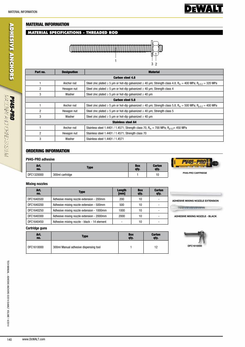
www.DEWALT.com140
TecH ManUal – aDHesIVe ancHoRs ©
2014 DeW
alT VolUMe 1 6/2014
ADHES
IVE A
NCHO
RS
MaTeRIal InfoRMaTIon
MATERIAL INFORMATION
MATERIAL SPECIFICATIONS - THREADED ROD
231
Part no. Designation Material
Carbon steel 4.8
1 anchor rod steel zinc plated ≥ 5 μm or hot-dip galvanized ≥ 40 μm; strength class 4.8, Rm = 400 MPa; Rp 0.2 = 320 MPa
2 Hexagon nut steel zinc plated ≥ 5 μm or hot-dip galvanized ≥ 40 μm; strength class 4
3 Washer steel zinc plated ≥ 5 μm or hot-dip galvanized ≥ 40 μm
Carbon steel 5.8
1 anchor rod steel zinc plated ≥ 5 μm or hot-dip galvanized ≥ 40 μm; strength class 5.8, Rm = 500 MPa; Rp 0.2 = 400 MPa
2 Hexagon nut steel zinc plated ≥ 5 μm or hot-dip galvanized ≥ 40 μm; strength class 5
3 Washer steel zinc plated ≥ 5 μm or hot-dip galvanized ≥ 40 μm
Stainless steel A4
1 anchor rod stainless steel 1.4401 / 1.4571; strength class 70, Rm = 700 MPa; Rp 0.2= 450 MPa
2 Hexagon nut stainless steel 1.4401 / 1.4571; strength class 70
3 Washer stainless steel 1.4401 / 1.4571
ORDERING INFORMATION
PV45-PRO adhesive
Art. no. Type Box
qty.Carton
qty.
Dfc1320000 300ml cartridge 1 10PV45-PRO CARTRIDGE
Mixing nozzles
Art. no. Type Length
[mm]Box qty.
Carton qty.
Dfc1640500 adhesive mixing nozzle extension - 200mm 200 10 -
Dfc1640200 adhesive mixing nozzle extension - 500mm 500 10 -
Dfc1640250 adhesive mixing nozzle extension - 1000mm 1000 10 -
Dfc1640300 adhesive mixing nozzle extension - 2000mm 2000 10 -
Dfc1640450 adhesive mixing nozzle - black - 14 element - 10 -
ADHESIVE MIXING NOZZLE EXTENSION
ADHESIVE MIXING NOZZLE - BLACK
Cartridge guns
Art. no. Type Box
qty.Carton
qty.
Dfc1610000 300ml Manual adhesive dispensing tool 1 12 DFC1610000
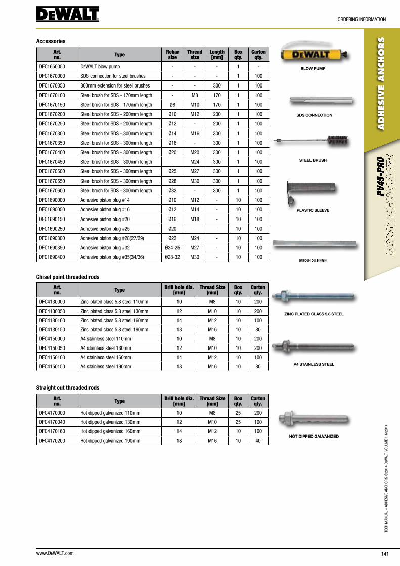
www.DEWALT.com 141
TecH
Man
Ual
– aD
HesI
Ve a
ncHo
Rs ©
2014
DeW
alT
Vol
UMe
1 6/
2014
ADHES
IVE
AN
CHO
RS
oRDeRInG InfoRMaTIon
Accessories
Art. no. Type Rebar
sizeThread
sizeLength[mm]
Box qty.
Carton qty.
Dfc1650050 DeWalT blow pump - - - 1 -
Dfc1670000 sDs connection for steel brushes - - - 1 100
Dfc1670050 300mm extension for steel brushes - - 300 1 100
Dfc1670100 steel brush for sDs - 170mm length - M8 170 1 100
Dfc1670150 steel brush for sDs - 170mm length Ø8 M10 170 1 100
Dfc1670200 steel brush for sDs - 200mm length Ø10 M12 200 1 100
Dfc1670250 steel brush for sDs - 200mm length Ø12 - 200 1 100
Dfc1670300 steel brush for sDs - 300mm length Ø14 M16 300 1 100
Dfc1670350 steel brush for sDs - 300mm length Ø16 - 300 1 100
Dfc1670400 steel brush for sDs - 300mm length Ø20 M20 300 1 100
Dfc1670450 steel brush for sDs - 300mm length - M24 300 1 100
Dfc1670500 steel brush for sDs - 300mm length Ø25 M27 300 1 100
Dfc1670550 steel brush for sDs - 300mm length Ø28 M30 300 1 100
Dfc1670600 steel brush for sDs - 300mm length Ø32 - 300 1 100
Dfc1690000 adhesive piston plug #14 Ø10 M12 - 10 100
Dfc1690050 adhesive piston plug #16 Ø12 M14 - 10 100
Dfc1690150 adhesive piston plug #20 Ø16 M18 - 10 100
Dfc1690250 adhesive piston plug #25 Ø20 - - 10 100
Dfc1690300 adhesive piston plug #28(27/29) Ø22 M24 - 10 100
Dfc1690350 adhesive piston plug #32 Ø24-25 M27 - 10 100
Dfc1690400 adhesive piston plug #35(34/36) Ø28-32 M30 - 10 100
BLOW PUMP
SDS CONNECTION
STEEL BRUSH
PLASTIC SLEEVE
MESH SLEEVE
Chisel point threaded rods
Art. no. Type Drill hole dia.
[mm]Thread Size
[mm]Box qty.
Carton qty.
Dfc4130000 Zinc plated class 5.8 steel 110mm 10 M8 10 200
Dfc4130050 Zinc plated class 5.8 steel 130mm 12 M10 10 200
Dfc4130100 Zinc plated class 5.8 steel 160mm 14 M12 10 100
Dfc4130150 Zinc plated class 5.8 steel 190mm 18 M16 10 80
Dfc4150000 a4 stainless steel 110mm 10 M8 10 200
Dfc4150050 a4 stainless steel 130mm 12 M10 10 200
Dfc4150100 a4 stainless steel 160mm 14 M12 10 100
Dfc4150150 a4 stainless steel 190mm 18 M16 10 80
Straight cut threaded rods
Art. no. Type Drill hole dia.
[mm]Thread Size
[mm]Box qty.
Carton qty.
Dfc4170000 Hot dipped galvanized 110mm 10 M8 25 200
Dfc4170040 Hot dipped galvanized 130mm 12 M10 25 100
Dfc4170160 Hot dipped galvanized 160mm 14 M12 10 100
Dfc4170200 Hot dipped galvanized 190mm 18 M16 10 40
ZINC PLATED CLASS 5.8 STEEL
A4 STAINLESS STEEL
HOT DIPPED GALVANIZED
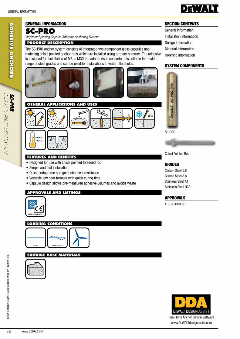
www.DEWALT.com142
TecH ManUal – aDHesIVe ancHoRs ©
2014 DeW
alT VolUMe 1 6/2014
ADHES
IVE A
NCHO
RS
GeneRal InfoRMaTIon
GENERAL INFORMATION
SC-PROVinylester Spinning Capsule Adhesive Anchoring System
PRODUCT DESCRIPTION
The sc-PRo anchor system consists of integrated two-component glass capsules and matching chisel pointed anchor rods which are installed using a rotary hammer. The adhesive is designed for installation of M8 to M30 threaded rods in concrete. It is suitable for a wide range of steel grades and can be used for installations in water filled holes.
GENERAL APPLICATIONS AND USES
-5˚C
40/24˚C
80/50˚C
FEATURES AND BENEFITS• Designed for use with chisel pointed threaded rod• simple and fast installation• Quick curing time and good chemical resistance• Versatile low odor formula with quick curing time• capsule design allows pre-measured adhesive volumes and avoids waste
APPROVALS AND LISTINGS
ETAG 001 Option 7
LOADING CONDITIONS
STATIC QUASI-STATIC
SUITABLE BASE MATERIALS
SECTION CONTENTSGeneral Information
Installation Information
Design Information
Material Information
ordering Information
SYSTEM COMPONENTS
sc-PRo
chisel Pointed Rod
GRADEScarbon steel 5.8
carbon steel 8.8
stainless steel a4
stainless steel HcR
APPROVALS• eTa-13/0051
DEWALT DESIGN ASSISTReal-Time anchor Design software
www.DeWalTdesignassist.com
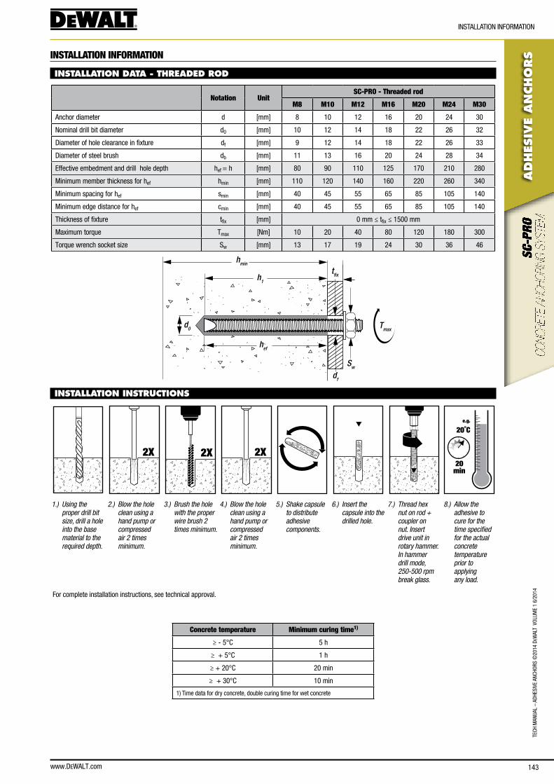
www.DEWALT.com 143
TecH
Man
Ual
– aD
HesI
Ve a
ncHo
Rs ©
2014
DeW
alT
Vol
UMe
1 6/
2014
ADHES
IVE
AN
CHO
RS
InsTallaTIon InfoRMaTIon
INSTALLATION INFORMATION
INSTALLATION DATA - THREADED ROD
Notation UnitSC-PRO - Threaded rod
M8 M10 M12 M16 M20 M24 M30
anchor diameter d [mm] 8 10 12 16 20 24 30
nominal drill bit diameter d0 [mm] 10 12 14 18 22 26 32
Diameter of hole clearance in fixture df [mm] 9 12 14 18 22 26 33
Diameter of steel brush db [mm] 11 13 16 20 24 28 34
effective embedment and drill hole depth hef = h [mm] 80 90 110 125 170 210 280
Minimum member thickness for hef hmin [mm] 110 120 140 160 220 260 340
Minimum spacing for hef smin [mm] 40 45 55 65 85 105 140
Minimum edge distance for hef cmin [mm] 40 45 55 65 85 105 140
Thickness of fixture tfix [mm] 0 mm ≤ tfix ≤ 1500 mm
Maximum torque Tmax [nm] 10 20 40 80 120 180 300
Torque wrench socket size sw [mm] 13 17 19 24 30 36 46
hmin
h1
hef
d0
Sw
Tmax
df
tfix
INSTALLATION INSTRUCTIONS
2X 2X 2X
e.g.
20˚C
20min
1.) Using the proper drill bit size, drill a hole into the base material to the required depth.
2.) Blow the hole clean using a hand pump or compressed air 2 times minimum.
3.) Brush the hole with the proper wire brush 2 times minimum.
4.) Blow the hole clean using a hand pump or compressed air 2 times minimum.
5.) Shake capsule to distribute adhesive components.
6.) Insert the capsule into the drilled hole.
7.) Thread hex nut on rod + coupler on nut. Insert drive unit in rotary hammer. In hammer drill mode, 250-500 rpm break glass.
8.) Allow the adhesive to cure for the time specified for the actual concrete temperature prior to applying any load.
for complete installation instructions, see technical approval.
Concrete temperature Minimum curing time1)
≥ - 5°c 5 h
≥ + 5°c 1 h
≥ + 20°c 20 min
≥ + 30°c 10 min
1) Time data for dry concrete, double curing time for wet concrete

www.DEWALT.com144
TecH ManUal – aDHesIVe ancHoRs ©
2014 DeW
alT VolUMe 1 6/2014
ADHES
IVE A
NCHO
RS
DesIGn InfoRMaTIon
DESIGN INFORMATION
TENSION LOAD CAPACITIES - PARAMETERS FOR CALCULATION OF DESIGN STRENGTHAccording to EOTA TR 029.
Notation UnitSC-PRO - Threaded rod
M8 M10 M12 M16 M20 M24 M30
Steel failure
Carbon steel
characteristic resistance, strength class 5.8 nRk,s [kn] 18 29 42 78 123 177 281
characteristic resistance, strength class 8.8 nRk,s [kn] 29 46 67 126 196 282 449
Partial safety factor gMs
1) [-] 1.50
A4 and HCR steel
characteristic resistance, strength class 50 nRk,s [kn] - - - - - - 281
characteristic resistance, strength class 70 nRk,s [kn] 26 40 59 110 172 247 -
Partial safety factor gMs
1) [-] 1.87 2.86
Combined pullout and concrete failure
Characteristic resistance in uncracked concrete, dry and wet concrete
Temperature Range: 40°c / 24°c tRk,uncr [n/mm²] 12 12 12 12 11 11 10
Temperature Range: 80°c / 50°c tRk,uncr [n/mm²] 10 10 10 10 9.5 9.5 9
Partial safety factor gMc = gMp
1) [-] 1.52) 1.83)
Increasing factor for concrete strength
c30/37 cc [-] 1.14
c40/50 cc [-] 1.26
c50/60 cc [-] 1.34
Concrete failure
Concrete cone failure
characteristic spacing scr,n [mm] 3.0·hef
characteristic edge distance ccr,n [mm] 1.5·hef
Partial safety factor gMc
1) [-] 1.52) 1.83)
Splitting failure
characteristic spacing scr,sp [mm] 2·ccr,sp
characteristic edge distance ccr,sp [mm] 160 135 140 160 215 265 350
Partial safety factor for uncracked concrete gMsp
1) [-] 1.52) 1.83)
Increasing factor for concrete strength
c30/37 cc [-] 1.21
c40/50 cc [-] 1.41
c50/60 cc [-] 1.55
1) In absence of other national regulations
2) Partial safety factor g2 = 1.0 is included
3) Partial safety factor g2 = 1.2 is included
DEWALT DESIGN ASSIST
The DeWalT Design assist is a powerful anchor design software which helps you to design simple and complex anchorages.The design data of all DeWalT anchor products is readily available. To download this software for free, go to www.DeWalTdesignassist.com
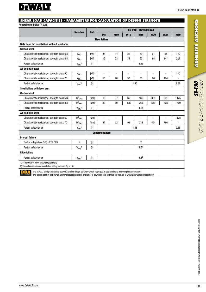
www.DEWALT.com 145
ADHES
IVE
AN
CHO
RS
DesIGn InfoRMaTIon
TecH
Man
Ual
– aD
HesI
Ve a
ncHo
Rs ©
2014
DeW
alT
Vol
UMe
1 6/
2014
SHEAR LOAD CAPACITIES - PARAMETERS FOR CALCULATION OF DESIGN STRENGTHAccording to EOTA TR 029.
Notation UnitSC-PRO - Threaded rod
M8 M10 M12 M16 M20 M24 M30
Steel failure
Data base for steel failure without level arm
Carbon steel
characteristic resistance, strength class 5.8 VRk,s [kn] 9 14 21 39 61 88 140
characteristic resistance, strength class 8.8 VRk,s [kn] 15 23 34 63 98 141 224
Partial safety factor gMs
1) [-] 1.25
A4 and HCR steel
characteristic resistance, strength class 50 VRk,s [kn] - - - - - - 140
characteristic resistance, strength class 70 VRk,s [kn] 13 20 30 55 86 124 -
Partial safety factor gMs
1) [-] 1.56 2.38
Steel failure with level arm
Carbon steel
characteristic resistance, strength class 5.8 M0Rk,s [nm] 19 37 65 166 325 561 1125
characteristic resistance, strength class 8.8 M0Rk,s [nm] 30 60 105 266 519 898 1799
Partial safety factor gMs
1) [-] 1.25
A4 and HCR steel
characteristic resistance, strength class 50 M0Rk,s [nm] - - - - - - 1125
characteristic resistance, strength class 70 M0Rk,s [nm] 26 52 92 233 454 786 -
Partial safety factor gMs
1) [-] 1.56 2.38
Concrete failure
Pry-out failure
factor in equation (5.7) of TR 029 k [-] 2
Partial safety factor gMcp
1) [-] 1.52)
Edge failure
Partial safety factor gMc
1) [-] 1.52)
1) In absence of other national regulations
2) The value contains an installation safety factor of g2 = 1.0
DEWALT DESIGN ASSIST
The DeWalT Design assist is a powerful anchor design software which helps you to design simple and complex anchorages.The design data of all DeWalT anchor products is readily available. To download this software for free, go to www.DeWalTdesignassist.com
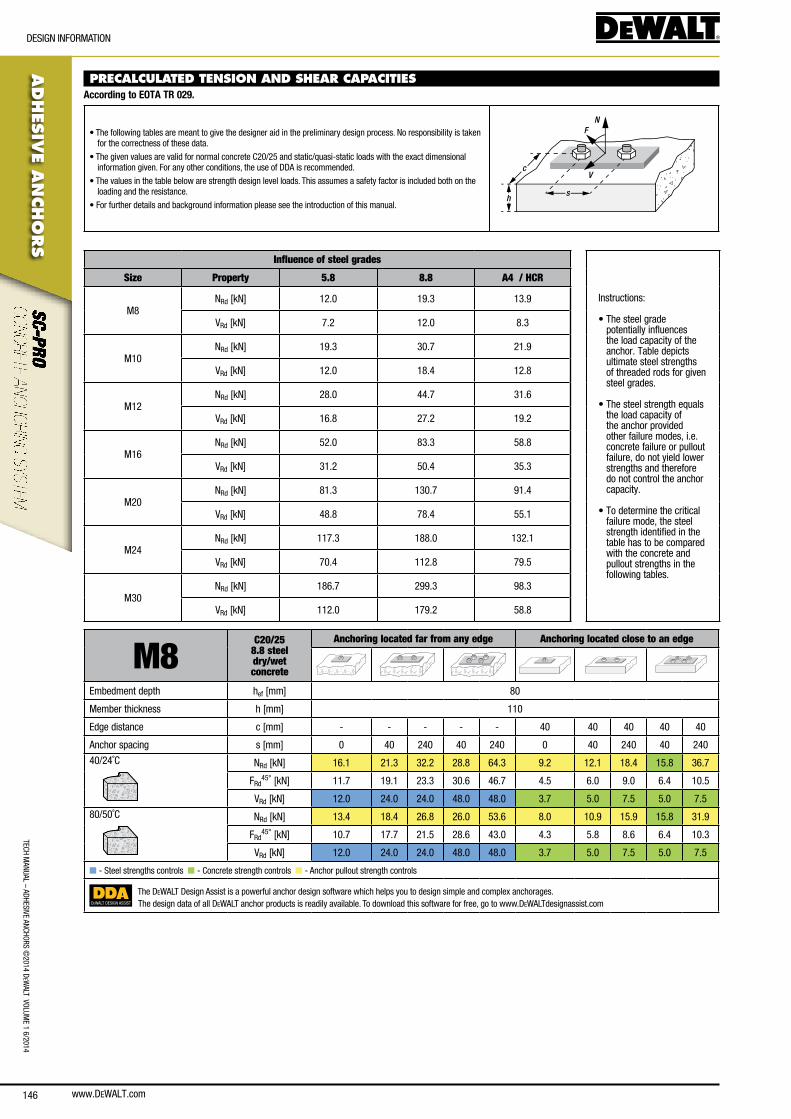
www.DEWALT.com146
ADHES
IVE A
NCHO
RS
DesIGn InfoRMaTIon
TecH ManUal – aDHesIVe ancHoRs ©
2014 DeW
alT VolUMe 1 6/2014
PRECALCULATED TENSION AND SHEAR CAPACITIES According to EOTA TR 029.
• The following tables are meant to give the designer aid in the preliminary design process. no responsibility is taken for the correctness of these data.
• The given values are valid for normal concrete c20/25 and static/quasi-static loads with the exact dimensional information given. for any other conditions, the use of DDa is recommended.
• The values in the table below are strength design level loads. This assumes a safety factor is included both on the loading and the resistance.
• for further details and background information please see the introduction of this manual.
N
V
F
sh
c
Influence of steel grades
Instructions:
• The steel grade potentially influences the load capacity of the anchor. Table depicts ultimate steel strengths of threaded rods for given steel grades.
• The steel strength equals the load capacity of the anchor provided other failure modes, i.e. concrete failure or pullout failure, do not yield lower strengths and therefore do not control the anchor capacity.
• To determine the critical failure mode, the steel strength identified in the table has to be compared with the concrete and pullout strengths in the following tables.
Size Property 5.8 8.8 A4 / HCR
M8nRd [kn] 12.0 19.3 13.9
VRd [kn] 7.2 12.0 8.3
M10nRd [kn] 19.3 30.7 21.9
VRd [kn] 12.0 18.4 12.8
M12nRd [kn] 28.0 44.7 31.6
VRd [kn] 16.8 27.2 19.2
M16nRd [kn] 52.0 83.3 58.8
VRd [kn] 31.2 50.4 35.3
M20nRd [kn] 81.3 130.7 91.4
VRd [kn] 48.8 78.4 55.1
M24nRd [kn] 117.3 188.0 132.1
VRd [kn] 70.4 112.8 79.5
M30nRd [kn] 186.7 299.3 98.3
VRd [kn] 112.0 179.2 58.8
M8C20/25
8.8 steel dry/wetconcrete
Anchoring located far from any edge Anchoring located close to an edge
embedment depth hef [mm] 80
Member thickness h [mm] 110
edge distance c [mm] - - - - - 40 40 40 40 40
anchor spacing s [mm] 0 40 240 40 240 0 40 240 40 240
40/24˚c nRd [kn] 16.1 21.3 32.2 28.8 64.3 9.2 12.1 18.4 15.8 36.7
fRd45° [kn] 11.7 19.1 23.3 30.6 46.7 4.5 6.0 9.0 6.4 10.5
VRd [kn] 12.0 24.0 24.0 48.0 48.0 3.7 5.0 7.5 5.0 7.5
80/50˚c nRd [kn] 13.4 18.4 26.8 26.0 53.6 8.0 10.9 15.9 15.8 31.9
fRd45° [kn] 10.7 17.7 21.5 28.6 43.0 4.3 5.8 8.6 6.4 10.3
VRd [kn] 12.0 24.0 24.0 48.0 48.0 3.7 5.0 7.5 5.0 7.5
n - steel strengths controls n - concrete strength controls n - anchor pullout strength controls
DEWALT DESIGN ASSIST
The DeWalT Design assist is a powerful anchor design software which helps you to design simple and complex anchorages.The design data of all DeWalT anchor products is readily available. To download this software for free, go to www.DeWalTdesignassist.com
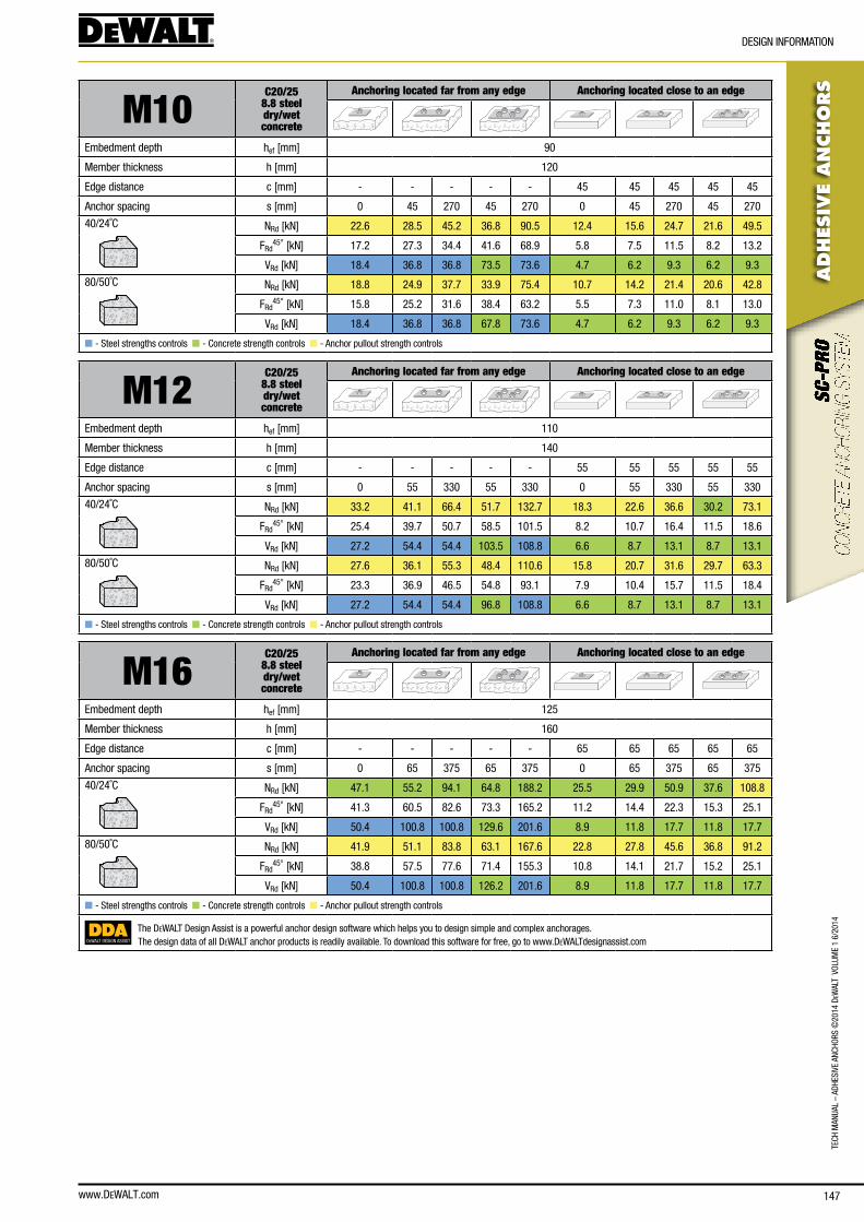
www.DEWALT.com 147
ADHES
IVE
AN
CHO
RS
DesIGn InfoRMaTIon
TecH
Man
Ual
– aD
HesI
Ve a
ncHo
Rs ©
2014
DeW
alT
Vol
UMe
1 6/
2014
M10C20/25
8.8 steel dry/wetconcrete
Anchoring located far from any edge Anchoring located close to an edge
embedment depth hef [mm] 90
Member thickness h [mm] 120
edge distance c [mm] - - - - - 45 45 45 45 45
anchor spacing s [mm] 0 45 270 45 270 0 45 270 45 270
40/24˚c nRd [kn] 22.6 28.5 45.2 36.8 90.5 12.4 15.6 24.7 21.6 49.5
fRd45° [kn] 17.2 27.3 34.4 41.6 68.9 5.8 7.5 11.5 8.2 13.2
VRd [kn] 18.4 36.8 36.8 73.5 73.6 4.7 6.2 9.3 6.2 9.3
80/50˚c nRd [kn] 18.8 24.9 37.7 33.9 75.4 10.7 14.2 21.4 20.6 42.8
fRd45° [kn] 15.8 25.2 31.6 38.4 63.2 5.5 7.3 11.0 8.1 13.0
VRd [kn] 18.4 36.8 36.8 67.8 73.6 4.7 6.2 9.3 6.2 9.3
n - steel strengths controls n - concrete strength controls n - anchor pullout strength controls
M12C20/25
8.8 steel dry/wetconcrete
Anchoring located far from any edge Anchoring located close to an edge
embedment depth hef [mm] 110
Member thickness h [mm] 140
edge distance c [mm] - - - - - 55 55 55 55 55
anchor spacing s [mm] 0 55 330 55 330 0 55 330 55 330
40/24˚c nRd [kn] 33.2 41.1 66.4 51.7 132.7 18.3 22.6 36.6 30.2 73.1
fRd45° [kn] 25.4 39.7 50.7 58.5 101.5 8.2 10.7 16.4 11.5 18.6
VRd [kn] 27.2 54.4 54.4 103.5 108.8 6.6 8.7 13.1 8.7 13.1
80/50˚c nRd [kn] 27.6 36.1 55.3 48.4 110.6 15.8 20.7 31.6 29.7 63.3
fRd45° [kn] 23.3 36.9 46.5 54.8 93.1 7.9 10.4 15.7 11.5 18.4
VRd [kn] 27.2 54.4 54.4 96.8 108.8 6.6 8.7 13.1 8.7 13.1
n - steel strengths controls n - concrete strength controls n - anchor pullout strength controls
M16C20/25
8.8 steel dry/wetconcrete
Anchoring located far from any edge Anchoring located close to an edge
embedment depth hef [mm] 125
Member thickness h [mm] 160
edge distance c [mm] - - - - - 65 65 65 65 65
anchor spacing s [mm] 0 65 375 65 375 0 65 375 65 375
40/24˚c nRd [kn] 47.1 55.2 94.1 64.8 188.2 25.5 29.9 50.9 37.6 108.8
fRd45° [kn] 41.3 60.5 82.6 73.3 165.2 11.2 14.4 22.3 15.3 25.1
VRd [kn] 50.4 100.8 100.8 129.6 201.6 8.9 11.8 17.7 11.8 17.7
80/50˚c nRd [kn] 41.9 51.1 83.8 63.1 167.6 22.8 27.8 45.6 36.8 91.2
fRd45° [kn] 38.8 57.5 77.6 71.4 155.3 10.8 14.1 21.7 15.2 25.1
VRd [kn] 50.4 100.8 100.8 126.2 201.6 8.9 11.8 17.7 11.8 17.7
n - steel strengths controls n - concrete strength controls n - anchor pullout strength controls
DEWALT DESIGN ASSIST
The DeWalT Design assist is a powerful anchor design software which helps you to design simple and complex anchorages.The design data of all DeWalT anchor products is readily available. To download this software for free, go to www.DeWalTdesignassist.com
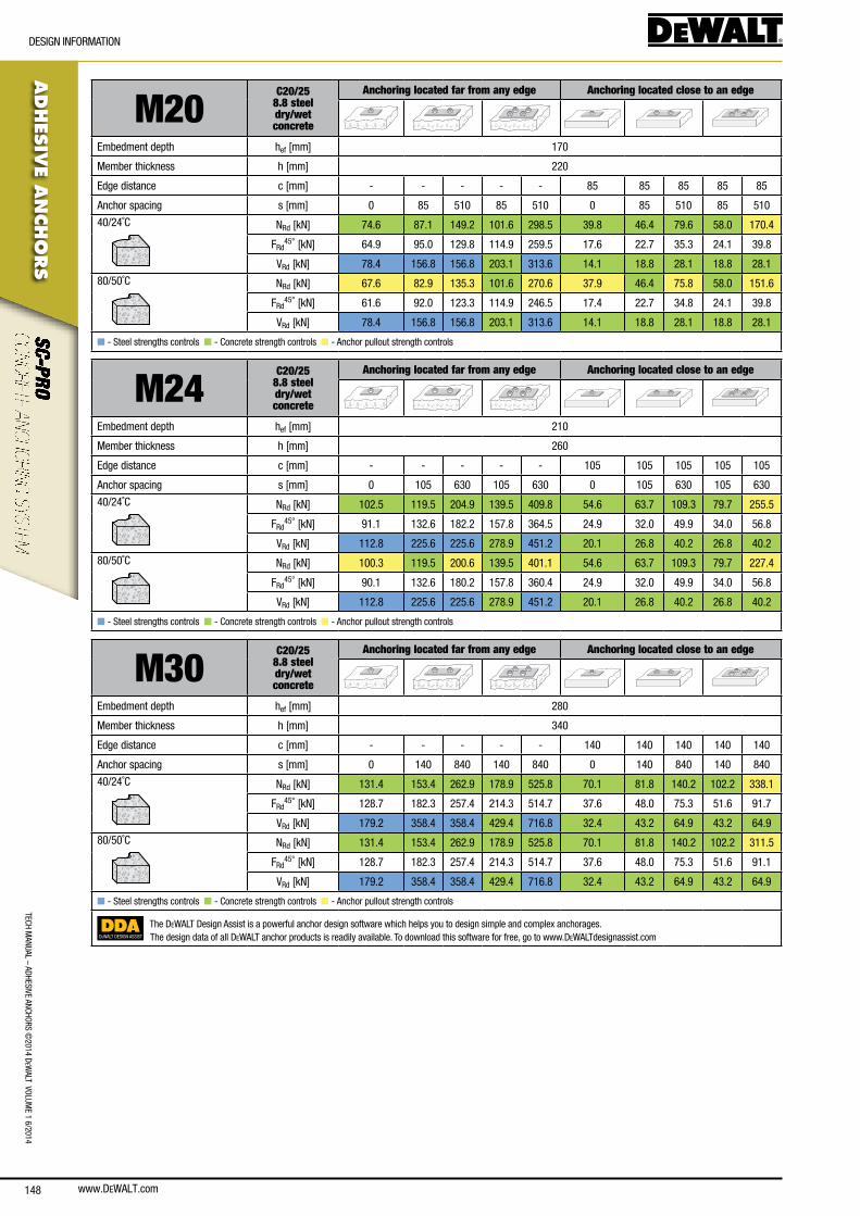
148
ADHES
IVE A
NCHO
RS
DesIGn InfoRMaTIon
TecH ManUal – aDHesIVe ancHoRs ©
2014 DeW
alT VolUMe 1 6/2014
www.DeWalT.com
M20C20/25
8.8 steel dry/wetconcrete
Anchoring located far from any edge Anchoring located close to an edge
embedment depth hef [mm] 170
Member thickness h [mm] 220
edge distance c [mm] - - - - - 85 85 85 85 85
anchor spacing s [mm] 0 85 510 85 510 0 85 510 85 510
40/24˚c nRd [kn] 74.6 87.1 149.2 101.6 298.5 39.8 46.4 79.6 58.0 170.4
fRd45° [kn] 64.9 95.0 129.8 114.9 259.5 17.6 22.7 35.3 24.1 39.8
VRd [kn] 78.4 156.8 156.8 203.1 313.6 14.1 18.8 28.1 18.8 28.1
80/50˚c nRd [kn] 67.6 82.9 135.3 101.6 270.6 37.9 46.4 75.8 58.0 151.6
fRd45° [kn] 61.6 92.0 123.3 114.9 246.5 17.4 22.7 34.8 24.1 39.8
VRd [kn] 78.4 156.8 156.8 203.1 313.6 14.1 18.8 28.1 18.8 28.1
n - steel strengths controls n - concrete strength controls n - anchor pullout strength controls
M24C20/25
8.8 steel dry/wetconcrete
Anchoring located far from any edge Anchoring located close to an edge
embedment depth hef [mm] 210
Member thickness h [mm] 260
edge distance c [mm] - - - - - 105 105 105 105 105
anchor spacing s [mm] 0 105 630 105 630 0 105 630 105 630
40/24˚c nRd [kn] 102.5 119.5 204.9 139.5 409.8 54.6 63.7 109.3 79.7 255.5
fRd45° [kn] 91.1 132.6 182.2 157.8 364.5 24.9 32.0 49.9 34.0 56.8
VRd [kn] 112.8 225.6 225.6 278.9 451.2 20.1 26.8 40.2 26.8 40.2
80/50˚c nRd [kn] 100.3 119.5 200.6 139.5 401.1 54.6 63.7 109.3 79.7 227.4
fRd45° [kn] 90.1 132.6 180.2 157.8 360.4 24.9 32.0 49.9 34.0 56.8
VRd [kn] 112.8 225.6 225.6 278.9 451.2 20.1 26.8 40.2 26.8 40.2
n - steel strengths controls n - concrete strength controls n - anchor pullout strength controls
M30C20/25
8.8 steel dry/wetconcrete
Anchoring located far from any edge Anchoring located close to an edge
embedment depth hef [mm] 280
Member thickness h [mm] 340
edge distance c [mm] - - - - - 140 140 140 140 140
anchor spacing s [mm] 0 140 840 140 840 0 140 840 140 840
40/24˚c nRd [kn] 131.4 153.4 262.9 178.9 525.8 70.1 81.8 140.2 102.2 338.1
fRd45° [kn] 128.7 182.3 257.4 214.3 514.7 37.6 48.0 75.3 51.6 91.7
VRd [kn] 179.2 358.4 358.4 429.4 716.8 32.4 43.2 64.9 43.2 64.9
80/50˚c nRd [kn] 131.4 153.4 262.9 178.9 525.8 70.1 81.8 140.2 102.2 311.5
fRd45° [kn] 128.7 182.3 257.4 214.3 514.7 37.6 48.0 75.3 51.6 91.1
VRd [kn] 179.2 358.4 358.4 429.4 716.8 32.4 43.2 64.9 43.2 64.9
n - steel strengths controls n - concrete strength controls n - anchor pullout strength controls
DEWALT DESIGN ASSIST
The DeWalT Design assist is a powerful anchor design software which helps you to design simple and complex anchorages.The design data of all DeWalT anchor products is readily available. To download this software for free, go to www.DeWalTdesignassist.com

www.DEWALT.com 149
TecH
Man
Ual
– aD
HesI
Ve a
ncHo
Rs ©
2014
DeW
alT
Vol
UMe
1 6/
2014
ADHES
IVE
AN
CHO
RS
MaTeRIal InfoRMaTIon
MATERIAL INFORMATION
MATERIAL SPECIFICATIONS - CHISEL POINTED THREADED ROD
231
Part no. Designation Material
Carbon steel 5.8
1 anchor rod steel zinc plated ≥ 5 μm or hot-dip galvanized ≥ 40 μm; strength class 5.8, Rm = 500 MPa; Rp 0.2 = 400 MPa
2 Hexagon nut steel zinc plated ≥ 5 μm or hot-dip galvanized ≥ 40 μm; strength class 5
3 Washer steel zinc plated ≥ 5 μm or hot-dip galvanized ≥ 40 μm
Carbon steel 8.8
1 anchor rod steel zinc plated ≥ 5 μm or hot-dip galvanized ≥ 40 μm; strength class 8.8, Rm = 800 MPa; Rp 0.2 = 640 MPa
2 Hexagon nut steel zinc plated ≥ 5 μm or hot-dip galvanized ≥ 40 μm; strength class 8
3 Washer steel zinc plated ≥ 5 μm or hot-dip galvanized ≥ 40 μm
Stainless steel A4
1 anchor rod stainless steel 1.4401 / 1.4571; strength class 50, Rm = 500 MPa; Rp 0.2= 210 MPa (for > M24)strength class 70, Rm = 700 MPa; Rp 0.2= 450 MPa (for ≤ M24)
2 Hexagon nut stainless steel 1.4401 / 1.4571; strength class 50 for class 50 rod; strength class 70 for class 70 rod
3 Washer stainless steel 1.4401 / 1.4571
Stainless steel HCR
1 anchor rod stainless steel 1.4529 / 1.4565; strength class 50, Rm = 500 MPa; Rp 0.2= 210 MPa (for > M24)strength class 70, Rm = 700 MPa; Rp 0.2= 450 MPa (for ≤ M24)
2 Hexagon nut stainless steel 1.4529 / 1.4565; strength class 50 for class 50 rod; strength class 70 for class 70 rod
3 Washer stainless steel 1.4529 / 1.4565
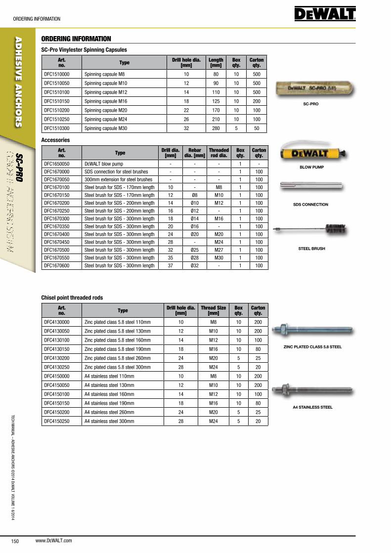
www.DEWALT.com150
TecH ManUal – aDHesIVe ancHoRs ©
2014 DeW
alT VolUMe 1 6/2014
ADHES
IVE A
NCHO
RS
oRDeRInG InfoRMaTIon
ORDERING INFORMATIONSC-Pro Vinylester Spinning Capsules
Art. no. Type Drill hole dia.
[mm]Length[mm]
Box qty.
Carton qty.
Dfc1510000 spinning capsule M8 10 80 10 500
Dfc1510050 spinning capsule M10 12 90 10 500
Dfc1510100 spinning capsule M12 14 110 10 500
Dfc1510150 spinning capsule M16 18 125 10 200
Dfc1510200 spinning capsule M20 22 170 10 100
Dfc1510250 spinning capsule M24 26 210 10 100
Dfc1510300 spinning capsule M30 32 280 5 50
SC-PRO
Accessories
Art. no. Type Drill dia.
[mm]Rebar
dia. [mm]Threaded rod dia.
Box qty.
Carton qty.
Dfc1650050 DeWalT blow pump - - - 1 -
Dfc1670000 sDs connection for steel brushes - - - 1 100
Dfc1670050 300mm extension for steel brushes - - - 1 100
Dfc1670100 steel brush for sDs - 170mm length 10 - M8 1 100
Dfc1670150 steel brush for sDs - 170mm length 12 Ø8 M10 1 100
Dfc1670200 steel brush for sDs - 200mm length 14 Ø10 M12 1 100
Dfc1670250 steel brush for sDs - 200mm length 16 Ø12 - 1 100
Dfc1670300 steel brush for sDs - 300mm length 18 Ø14 M16 1 100
Dfc1670350 steel brush for sDs - 300mm length 20 Ø16 - 1 100
Dfc1670400 steel brush for sDs - 300mm length 24 Ø20 M20 1 100
Dfc1670450 steel brush for sDs - 300mm length 28 - M24 1 100
Dfc1670500 steel brush for sDs - 300mm length 32 Ø25 M27 1 100
Dfc1670550 steel brush for sDs - 300mm length 35 Ø28 M30 1 100
Dfc1670600 steel brush for sDs - 300mm length 37 Ø32 - 1 100
BLOW PUMP
SDS CONNECTION
STEEL BRUSH
Chisel point threaded rods
Art. no. Type Drill hole dia.
[mm]Thread Size
[mm]Box qty.
Carton qty.
Dfc4130000 Zinc plated class 5.8 steel 110mm 10 M8 10 200
Dfc4130050 Zinc plated class 5.8 steel 130mm 12 M10 10 200
Dfc4130100 Zinc plated class 5.8 steel 160mm 14 M12 10 100
Dfc4130150 Zinc plated class 5.8 steel 190mm 18 M16 10 80
Dfc4130200 Zinc plated class 5.8 steel 260mm 24 M20 5 25
Dfc4130250 Zinc plated class 5.8 steel 300mm 28 M24 5 20
Dfc4150000 a4 stainless steel 110mm 10 M8 10 200
Dfc4150050 a4 stainless steel 130mm 12 M10 10 200
Dfc4150100 a4 stainless steel 160mm 14 M12 10 100
Dfc4150150 a4 stainless steel 190mm 18 M16 10 80
Dfc4150200 a4 stainless steel 260mm 24 M20 5 25
Dfc4150250 a4 stainless steel 300mm 28 M24 5 20
ZINC PLATED CLASS 5.8 STEEL
A4 STAINLESS STEEL

www.DEWALT.com 151
TecH
Man
Ual
– aD
HesI
Ve a
ncHo
Rs ©
2014
DeW
alT
Vol
UMe
1 6/
2014
www.DEWALT.com152
TecH ManUal – aDHesIVe ancHoRs ©
2014 DeW
alT VolUMe 1 6/2014
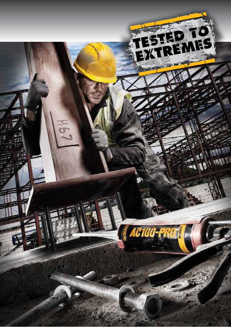

06/2014 MP16771-GB


![DEWALT DW708 12 Double-Bevel Sliding Compound Miter Manual[1]](https://static.cupdf.com/doc/110x72/55cf9ded550346d033afe25e/dewalt-dw708-12-double-bevel-sliding-compound-miter-manual1.jpg)