L:\Projects\Elcon\1065\EV171065.01\Part B\Final\Section N\N-All.docx\saq N-ii
TABLE OF CONTENTS
SECTION N SUBPART BB EQUIPMENT LEAKS N-1
N-1 APPLICABILITY N-1
N-1a Applicability N-1
N-1b Definition of Equipment N-6
N-1c Equipment Excluded N-6
N-2 PUMPS IN LIGHT LIQUID SERVICE N-6
N-2a Monthly Monitoring for Leaks N-6
N-2b Visual Inspection for Pump Seal Leaks N-6
N-2c Leak Detection N-7
N-2d Leak Repair as Soon As Practicable N-7
N-2e Specific Exceptions to These Standards N-7
N-3 COMPRESSORS N-8
N-4 PRESSURE RELIEF DEVICES IN GAS/VAPOR SERVICE N-9
N-4a No Detectable Emissions N-9
N-4b Return to No Detectable Emissions N-9
N-4c Specific Exceptions to These Standards N-9
N-5 SAMPLING CONNECTION SYSTEMS N-9
N-5a Closed Sampling Connection Systems N-9
N-5b Exemption for Qualified Sampling Systems N-10
N-6 OPEN ENDED VALVES OR LINES N-10
N-6a Open-Ended Valve or Line N-10
N-6b Second Valve N-10
N-7 VALVES IN GAS/VAPOR SERVICE OR IN LIGHT LIQUID SERVICE N-10
N-7A Exceptions to the Monitoring Schedule N-11
N-8 PRESSURE RELIEF DEVICES, FLANGES, AND OTHER CONNECTORS N-12
N-8a Monitoring N-13
N-8b Leak Detection N-13
N-8c Leak Repair As Soon As Practicable N-13
N-8d Inaccessible Connectors N-14
N-9 ALLOWANCES FOR DELAY OF REPAIR N-14
N-10 CLOSED-VENT SYSTEMS AND CONTROL DEVICES N-15

L:\Projects\Elcon\1065\EV171065.01\Part B\Final\Section N\N-All.docx\saq N-iii
N-11 ALTERNATIVE MONITORING PROGRAM N-15
N-12 ALTERNATIVE WORK PRACTICE N-16
N-13 RECORDKEEPING REQUIREMENTS N-16
N-13a Semiannual Report N-20
N-13b Implementation Schedule N-21
N-13c Performance Test Plan N-21
N-14 TEST METHODS AND PROCEDURES N-21
TABLES
TABLE N-1 - EQUIPMENT SUBJECT TO LEAK REQUIREMENTS N-3
TABLE N-2 - OVERVIEW OF EQUIPMENT SUBJECT TO SUBPART BB N-5
FIGURES
FIGURE N-1 – APPLICABILITY OF SUBPART BB REGULATIONS N-2
APPENDICES
APPENDIX N-1 – EXAMPLES OF EQUIPMENT SUBJECT TO SUBPART BB
REGULATIONS

L:\Projects\Elcon\1065\EV171065.01\Part B\Final\Section N\N-All.docx\saq N-1
SECTION N
SUBPART BB EQUIPMENT LEAKS
N-1 APPLICABILITY
N-1a Applicability
The information presented in this section is being submitted as required under 40 CFR 264
Subpart BB, and applies to equipment that contains or is in contact with hazardous waste with
organic concentrations of at least 10% by weight associated with hazardous waste treatment or
storage systems. While incoming waste streams will average about 3% organics by weight,
equipment in portions of the treatment facility will exceed the 10% concentration since the
organic constituents are more concentrated in the incoming waste stream or are concentrated as
the constituents are removed from the waste stream as part of the treatment process. Equipment
leak emission standards apply to equipment in these areas.
The EPA definition of a leak for most of the equipment subject to the RCRA leak detection
program is 10,000 ppm or greater. Elcon is voluntarily agreeing to lower this threshold to 500
ppm.
The equipment identified in this section is subject to permitting requirements under the RCRA
program.
Figure N-1 is a simplified facility diagram that shows the portions of the Elcon facility waste
treatment system to which 40 CFR 264 Subpart BB applies.
Equipment subject to 40 CFR Subpart BB includes pumps, pressure relief valves, sampling
connection lines, open-ended valves or lines, and valves in gas/vapor or in light liquid service in
the following process areas:
Incoming waste storage tank T-20357 in the flammable containment areas at the
unloading point and equipment in the process train (heat exchanger H-203XX) through
the exhaust to the thermal oxidizer
Incoming waste storage tanks T-23100 and T-23101 in the flammable containment area
at the unloading point and equipment in the process train up to the Flash Evaporative
Distillation (FED) unit. The process train varies depending on the waste stream.
There are no compressors proposed for the facility that will process organic materials above
10%.
Figure N-1 indicates which streams (and thus which equipment) are in vapor service and which
are in liquid service. These liquid streams will qualify as light liquid service.

Holding Tanks
Unit 20
Sludge 5%
solids
Sludge OvenSteam
to Power
Solids disposal
Holding Tanks
Unit 21
Filtrate
water
Holding Tanks
Unit 12
Holding Tanks
Unit 23
Organic vapor
Filtrate
return
Thermal oxidizer+
Waste heat boiler
Filtrate water+Salts+organics
Steamfromboiler
Raw wastewater
Raw wastewater
Raw wastewater
Steam +organics
Chemical-
Physical
Pre-treatment
Chemical-
Physical
Pre-treatment
DistilledCondensate
water
FlashEvaporationDistillation
To atmosphere
SaltsCrystallizer
SaltsDryer/Thin
Film Evaporator
Solid SaltsDisposal
Biologicaltreatment
R.O. Scrubber
system
Use for cooling towers
Treatment Process/
Distillation Column
Vapors toThermal oxidizer
Filter Press
Treated Water
Option: To
Biological
Treatment
Vapors
Vapors to Thermal Oxidizer
Vapors to Thermal Oxidizer
Vapors to Thermal Oxidizer
10-30% organics
Heat ExchangerOrganic vaporRaw wastewater
>30% organics
Chemical-
Physical
Pre-treatment
FIGURE N-1Equipment Subject to Equipment Leak Requirements
KEY- Equipment (Valves, flanges, etc) Subject to
Subpart BB requirements

L:\Projects\Elcon\1065\EV171065.01\Part B\Final\Section N\N-All.docx\saq N-3
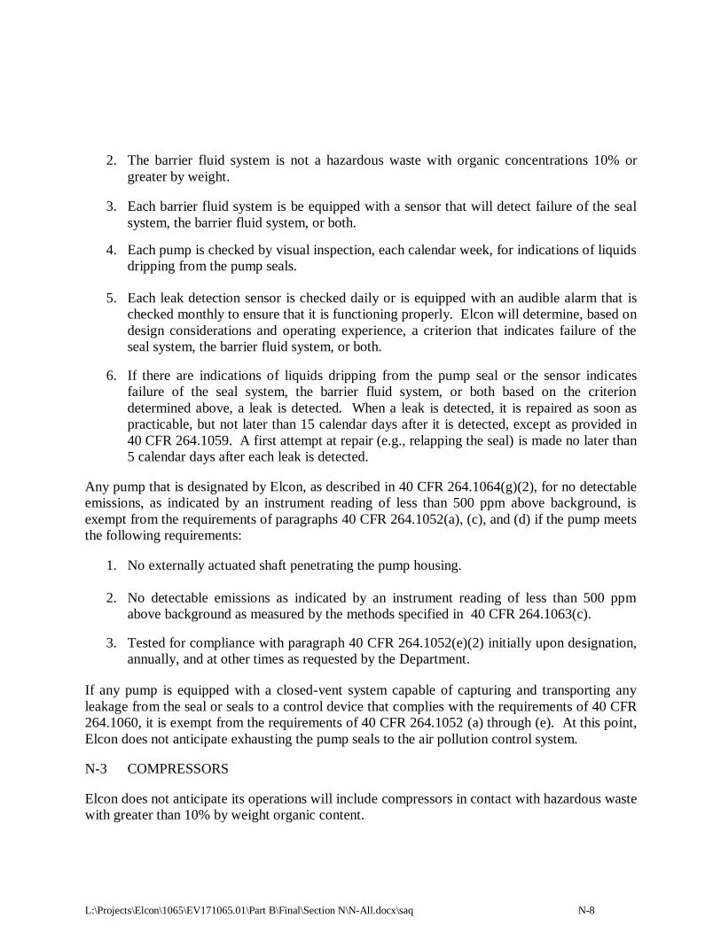
TABLE N-1
EQUIPMENT SUBJECT TO LEAK REQUIREMENTS
Starting Unit1 Starting
Unit ID
Process Train
Description
PFD Nos.2 P&ID Nos.
3
Storage tank (>
30% organics)
T-20357 Equipment from tank
unloading through heat
exchanger (H-203XX) and exhaust to thermal
oxidizer
USA-20100-01-100
USA-20300-01-101
USA 23100-01-001
USA-20300-01-002
USA-20300-01-011 USA-20300-01-012
Storage tanks (10-
30% organics)
T-23100
T-23101
Equipment from tank
unloading to Flash Evaporative Distillation
(FED) unit with option
from filter press (FP-20218C) to C-23344
and exhaust to oxidizer
USA-20100-01-100
USA-23100-01-100 USA-23200-01-100
USA-20200-01-104
USA-20300-01-100 USA-20200-01-100
USA-20400-01-100
USA-20200-01-101 USA-20300-01-101
USA-20100-01-001
USA-23100-01-001 USA-23200-01-001
USA-20200-01-003
USA-20200-01-006
USA-20400-01-001A USA-20400-01-001B
USA-20300-01-012
1 Includes lines and equipment in the process train associated with each piece of equipment listed, such as
(but not limited to) in-process tanks, reactors, heat exchangers, valves, flanges, and pumps. Final
determination of applicability of individual piece of equipment will be made at start-up. 2 See Appendix D-8 of Section D of this application.
3 See Appendix D-7 of Section D of this application.
The process train units that are subject to Subpart BB are shown on Table N-1. This table also
provides the references to process flow diagrams (PFDs) and piping and instrumentation
diagrams (P&IDs) that are included in Appendices D-7 and D-8 in Section D of this application
that provide additional details on the process and equipment. The P&IDs show the equipment
number and hazardous waste unit identification.
The PFDs and P&IDs referenced on Table N-1 are preliminary designs. Elcon expects that there
will be approximately 120 pumps, 1,000 valves, 120 blind flanges, and 2,300 regular flanges in
the facility, although not all of these will be subject to Subpart BB requirements because of the
low organic content of some of the treatment process (e.g., pH neutralization).
The equipment that is subject to Subpart BB is located within the flammable secondary
containment area for storage tanks (Area 6) or the Treatment Building (Area 5) on Figure D-1 in
Section D of this application. Drawings C-101 and C-102 in Appendix B-1 of Section B of this
application provide additional details of the facility layout and the equipment location. Drawings
S104 (incoming storage tanks) and S102A through S102D (equipment in the Treatment

L:\Projects\Elcon\1065\EV171065.01\Part B\Final\Section N\N-All.docx\saq N-4
Building) in Appendix D-1 of Section D of this application show the specific locations of the
individual pieces of equipment that are subject to Subpart BB.
Table N-2 provides an overview of the equipment involved, compliance standard, and other
information indicated under 40 CFR Part 270.25(a) for equipment subject to Subpart BB.
Appendix N-2 provides examples of the various types of equipment that is subject to Subpart
BB.
The reference to 40 CFR 270.25(b) and (c) for this section on the Department’s checklist is not
applicable to Elcon’s operations. The required equipment will be in place prior to start-up; an
implementation plan is not required under 40 CFR 270.25(b). A performance plan is not
required under 270.25(c) since Elcon is not seeking to use an alternate control technology.
Information related to 40 CFR 270.25(d) demonstrating compliance with 40 CFR 264.1052 to
264.1059, excluding 264.1053 is provided in Sections N-2 through N-9 below. The records that
will be maintained to document compliance are identified in Section N-13. Attachment N-1 to
this section provides examples of typical equipment that will be used at the proposed facility.
Information related to 40 CFR 270.25(e), related to documentation for compliance with 40 CFR
264.1060 (standards: closed-vent systems and control devices) is provided in Section M of this
application, including a signed statement from Elcon’s owner.
Once the facility is operational, Elcon will mark the equipment subject to Subpart BB such that it
is readily distinguishable from other pieces of equipment.

L:\Projects\Elcon\1065\EV171065.01\Part B\Final\Section N\N-All.docx\saq N-5
TABLE N-2
OVERVIEW OF EQUIPMENT SUBJECT TO SUBPART BB
Type of Equipment1 ID Numbers Organic
Content (%)
Material
State
Proposed
Method of
Compliance
Storage Tank T-20357 Unloading through Thermal Oxidizer
Light liquid pumps P-23102, P-20358 30% - 70% liquid Visual
inspection/LDAR2
Gas/vapor pressure relief
devices PSV for H-203XX 30% - 70% gas/vapor LDAR
Sampling connection
systems 1 30% - 70% liquid LDAR
Open-ended valves or
lines3
21 30% - 70% various LDAR
Gas/vapor or light liquid
valves3
71 30% - 70% various LDAR
Light liquid pressure
relief devices None NA NA NA
Storage Tanks T-23100 and T-23101 Unloading through FED Unit
Light liquid pumps
P-23102, P-20358, P-
20111, P-20114, P-
23202, P-23204, P-
23205, P-23207, P-20207A, P-20207B, P-
20247, P-20208, P-
20219, P-20425, P-20412, P-20413, P-20405
10% -30% liquid Visual inspection/LDAR
Gas/vapor pressure relief
devices
PSV for H-203XX, PSV-
233221, PSV-204146 10% - 30% gas/vapor LDAR
Sampling connection systems
2 10% - 30% liquid LDAR
Open-ended valves or
lines3
60 10% - 30% various LDAR
Gas/vapor or light liquid valves
3
252 10% - 30% various LDAR
Light liquid pressure
relief devices
PSV-233232, PSV-
233233 10% - 30% liquid LDAR
1 Details on the flanges are not available at this point as discussed with the Department during
the pre-application meeting. However, ultimately, the flanges will comply with Subpart BB
requirements. Final determination of applicability of individual pieces of equipment will be
made at start-up. Elcon anticipates demonstrating compliance by visual inspection, LDAR,
or other regulatory-approved method. 2 LDAR – leak detection and repair program 3 Not including check valves and valves on lines containing non-organic materials (e.g., plant,
water, ultrafiltration water), nitrogen, and plant air.

L:\Projects\Elcon\1065\EV171065.01\Part B\Final\Section N\N-All.docx\saq N-6
N-1b Definition of Equipment
Under 40 CFR 264.1031, equipment means each valve, pump, compressor, pressure relief
device, sampling connection system, open-ended valve or line, or flange or other connector, and
any control devices or systems required by this subpart. Elcon will use equipment subject to
Subpart BB that meets this definition. Elcon will not operate any compressors that are subject to
Subpart BB requirements.
Information related to 40 CFR 270.25 on the Department’s checklist is provided in other
locations in this Section.
N-1c Equipment Excluded
Elcon’s process does not include any equipment that contains hazardous waste with an organic
concentration of at least 10 percent by weight for a period of less than 300 hours per calendar
year or equipment with an organic concentration of at least 10 percent in vacuum service.
N-2 PUMPS IN LIGHT LIQUID SERVICE
Elcon’s operations will include pumps in light liquid service. As required by 40 CFR 270.25(d),
related to compliance demonstration, this section contains information related to compliance
with the elements of 40 CFR 264.1052. Information related to documentation that will be
maintained to demonstrate compliance is provided in Section N-13.
N-2a Monthly Monitoring For Leaks
The equipment identified during final design for monitoring under 40 CFR 264 Subpart BB will
be monitored as required by the regulations for the type of equipment and the type of service.
Since the equipment used in the Elcon process will be exposed to wastes of varying types, the
equipment will be monitored for light liquid service, which is the most stringent monitoring
program. The test method will be Reference Method 21 in 40 CFR Part 60 in accordance with 40
CFR Part 264.1063.
When a leak is detected during leak monitoring, the leaking equipment will be tagged with a
weatherproof and readily visible identification tag. The identification tag will specify the
equipment identification number and the date when the leak was detected. The tag will remain
on the equipment until the leak is repaired. For valves, the tag will remain on the equipment
until it has been monitored for two successive months following the repair with no leaks
detected.
N-2b Visual Inspection for Pump Seal Leaks
Elcon will have a comprehensive preventive inspection and maintenance program for the facility
that will include visual inspections for all pump seals for leakage on at least a calendar week
basis. The inspection will check for indications of liquids dripping from the pump seal.

L:\Projects\Elcon\1065\EV171065.01\Part B\Final\Section N\N-All.docx\saq N-7
N-2c Leak Detection
The Elcon leak detection program will indicate a leak is detected if one of the following occurs:
1) the leak detection instrument reads 500 parts per million (ppm), or greater, or 2) there are
indications of liquid dripping from the pump seal. Leak detection monitoring will comply with
the requirements outlined in 40 CFR 264.1063 and 40 CFR Part 60 Reference Method 21 as
further described in Section N-14.
N-2d Leak Repair as Soon as Practicable
Elcon will ensure repairs are made to any leaks detected as soon as practicable, but no later than
15 calendar days after detection. As allowed under 40 CFR 264.1059, extensions to the time
allowed for repair may occur under the following conditions:
If the repair is technically infeasible without a hazardous waste management unit
shutdown. In this case, repair of the equipment will occur before the end of the next
hazardous waste management unit shutdown.
If the equipment needing repair is isolated from the hazardous waste management unit
and does not continue to contain or contact hazardous waste with organic concentrations
at least 10% by weight.
For pumps:
o If repair requires the use of a dual mechanical seal system that includes a barrier
fluid system
o If repair is completed as soon as practicable, but not later than 6 months after the
leak was detected.
N-2e Specific Exemptions to These Standards
Each pump equipped with a dual mechanical seal system that includes a barrier fluid system is
exempt from the requirements of paragraph 40 CFR.1052(a), related to monthly monitoring,
provided that Elcon meets the following requirements:
1. Each dual mechanical seal system is:
Operated with the barrier fluid at a pressure that is at all times greater than the pump
stuffing box pressure, or
Equipped with a barrier fluid degassing reservoir that is connected by a closed-vent
system to a control device that complies with the requirements of §264.1060, or
Equipped with a system that purges the barrier fluid into a hazardous waste stream
with no detectable emissions to the atmosphere.
L:\Projects\Elcon\1065\EV171065.01\Part B\Final\Section N\N-All.docx\saq N-8
2. The barrier fluid system is not a hazardous waste with organic concentrations 10% or
greater by weight.
3. Each barrier fluid system is be equipped with a sensor that will detect failure of the seal
system, the barrier fluid system, or both.
4. Each pump is checked by visual inspection, each calendar week, for indications of liquids
dripping from the pump seals.
5. Each leak detection sensor is checked daily or is equipped with an audible alarm that is
checked monthly to ensure that it is functioning properly. Elcon will determine, based on
design considerations and operating experience, a criterion that indicates failure of the
seal system, the barrier fluid system, or both.
6. If there are indications of liquids dripping from the pump seal or the sensor indicates
failure of the seal system, the barrier fluid system, or both based on the criterion
determined above, a leak is detected. When a leak is detected, it is repaired as soon as
practicable, but not later than 15 calendar days after it is detected, except as provided in
40 CFR 264.1059. A first attempt at repair (e.g., relapping the seal) is made no later than
5 calendar days after each leak is detected.
Any pump that is designated by Elcon, as described in 40 CFR 264.1064(g)(2), for no detectable
emissions, as indicated by an instrument reading of less than 500 ppm above background, is
exempt from the requirements of paragraphs 40 CFR 264.1052(a), (c), and (d) if the pump meets
the following requirements:
1. No externally actuated shaft penetrating the pump housing.
2. No detectable emissions as indicated by an instrument reading of less than 500 ppm
above background as measured by the methods specified in 40 CFR 264.1063(c).
3. Tested for compliance with paragraph 40 CFR 264.1052(e)(2) initially upon designation,
annually, and at other times as requested by the Department.
If any pump is equipped with a closed-vent system capable of capturing and transporting any
leakage from the seal or seals to a control device that complies with the requirements of 40 CFR
264.1060, it is exempt from the requirements of 40 CFR 264.1052 (a) through (e). At this point,
Elcon does not anticipate exhausting the pump seals to the air pollution control system.
N-3 COMPRESSORS
Elcon does not anticipate its operations will include compressors in contact with hazardous waste
with greater than 10% by weight organic content.

L:\Projects\Elcon\1065\EV171065.01\Part B\Final\Section N\N-All.docx\saq N-9
N-4 PRESSURE RELIEF DEVICES IN GAS/VAPOR SERVICE
Elcon’s operations will include pressure relief valves in gas/vapor service. As required by 40
CFR 270.25(d), related to compliance demonstration, this section contains information related
compliance with the elements of 40 CFR 264.1054. Information related to documentation that
will be maintained to demonstrate compliance is provided in Section N-13.
N-4a No Detectable Emissions
Pressure relief devices will be set such that emissions from pressure relief devices will be less
than a 500-ppm instrument reading above background levels unless there is a reason for the
pressure relief valve to activate. Measurements will be made in accordance with the monitoring
requirements of 40 CFR 264.1063(c) as described in Section N-14.
N-4b Return to No Detectable Emissions
Elcon will take appropriate measures within 5 calendar days to ensure that no detectable
emissions will occur from a pressure release device that has been activated. To accomplish this,
Elcon will re-set the pressure relief device to ensure emissions are less than 500 ppm above
background levels. The relief valve will be monitored within 5 calendar days after a pressure
relief in accordance with the monitoring requirements of 40 CFR 264.1063(c) as described in
Section N-14.
N-4c Specific Exemptions to These Standards
Certain closed vent systems are exempted from these requirements if the pressure relief vents to
an air pollution control device. In Elcon’s process, the pressure relief vents from the four
flammable liquid storage tanks will be vented to the thermal oxidizer.
N-5 SAMPLING CONNECTION SYSTEMS
Elcon’s operations will include sampling connections. As required by 40 CFR 270.25(d), related
to compliance demonstration, this section contains information related to compliance with the
elements of 40 CFR 264.1054. Information related to documentation that will be maintained to
demonstrate compliance is provided in Section N-13.
N-5a Closed Sampling Connection Systems
At Elcon, each sampling connection system will be equipped with a closed-purge, closed-loop,
or closed-vent system. Each of these systems will either: 1) return the purged process fluid
directly to a process line, 2) collect and recycle purged process liquid, or 3) be designed and
operated to capture and transport all purged process fluid to a waste management unit that
complies with the requirements of 40 CFR 264.1084 to .1086 or a control device that meets the
requirements of 40 CFR 264.1060. Elcon is proposing to use sampling systems as described in
item 1 or 2.

L:\Projects\Elcon\1065\EV171065.01\Part B\Final\Section N\N-All.docx\saq N-10
N-5b Exemption for Qualified Sampling Systems
Under 40 CFR 264.1055(c), any in-situ sampling systems and sampling systems without purges
that Elcon installs are exempt from the requirements of 40 CFR 264.1055(a) and(b).
N-6 OPEN-ENDED VALVES OR LINES
Elcon’s operations will have open-ended valves or lines. As required by 40 CFR 270.25(d),
related to compliance demonstration, this section contains information related to compliance
with the elements of 40 CFR 264.1056. Information related to documentation that will be
maintained to demonstrate compliance is provided in Section N-13.
N-6a Open-ended Valve or Line Requirements
Each open-ended valve or line will be equipped with a cap, blind flange, plug, or a second valve.
The cap, blind flange, plug, or second valve will seal the open end at all times except during
operations requiring hazardous waste stream flow through the open-ended valve or line.
When a double block and bleed system is being used, the bleed valve or line may remain open
during operations that require venting the line between the block valves but will comply with the
requirements of the above paragraph at all other times.
N-6b Second Valve
Each open-ended valve or line equipped with a second valve will be operated in a manner such
that the valve on the hazardous waste stream end is closed before the second valve is closed.
N-7 VALVES IN GAS/VAPOR SERVICE OR LIGHT LIQUID SERVICE
Elcon’s operations will include valves in gas/vapor service or light liquid service. As required
by 40 CFR 270.25(d), related to compliance demonstration, this section contains information
related to compliance with the elements of 40 CFR 264.1057. Information related to
documentation that will be maintained to demonstrate compliance is provided in Section N-13.
Each valve in gas/vapor or light liquid service shall be monitored monthly to detect leaks by the
methods specified in 40 CFR 264.1063(b) as discussed under Section N-14. Specifically,
Elcon’s monitoring program will include the following:
1. If an instrument reading of 500 ppm or greater is measured, a leak is detected.
2. Any valve for which a leak is not detected for two successive months may be monitored
the first month of every succeeding quarter, beginning with the next quarter, until a leak
is detected. If a leak is detected, the valve will be monitored monthly until a leak is not
detected for two successive months

L:\Projects\Elcon\1065\EV171065.01\Part B\Final\Section N\N-All.docx\saq N-11
3. When a leak is detected, it will be repaired as soon as practicable, but no later than 15
calendar days after the leak is detected, except as provided in 40 CFR 264.1059. The
first attempt at repair will be made no later than 5 calendar days after each leak is
detected.
4. First attempts at repair include, but are not limited to, the following best practices where
practicable: 1) tightening of bonnet bolts, 2) replacement of bonnet bolts, 3) tightening of
packing gland nuts, and 4) injection of lubricant into lubricated packing.
N-7a Exceptions to the Monitoring Schedule
Any valve that is designated, as described in 40 CFR 264.1064(g)(2), for no detectable
emissions, as indicated by an instrument reading of less than 500 ppm above background, is
exempt from the monthly requirements of 40 CFR 264.1057(a) if the valve:
1. Has no external actuating mechanism in contact with the hazardous waste stream.
2. Is operated with emissions less than 500 ppm above background as determined by the
method specified in §264.1063(c).
3. Is tested for compliance with paragraph (f)(2) of this section initially upon designation,
annually, and at other times as requested by the Department.
Elcon does not anticipate any unsafe-to-monitor valves in its operations. However, in the event
that there are, any valve that is designated, as described in 40 CFR 264.1064(h)(1), as an unsafe-
to-monitor valve is exempt from the requirements of 40 CFR 264.1057(a) if:
1. Elcon determines that the valve is unsafe-to-monitor because monitoring personnel would
be exposed to an immediate danger as a consequence of complying with the monitoring
requirements.
2. Elcon adheres to a written plan that requires monitoring of the valve as frequently as
practicable during safe-to-monitor times.
Any valve that is designated, as described in §264.1064(h)(2), as a difficult-to-monitor
valve is exempt from the monitoring requirements if:
Elcon determines that the valve cannot be monitored without elevating the monitoring
personnel more than 2 meters above a support surface.
Elcon follows a written plan that requires monitoring of the valve at least once per
calendar year.
As allowed under 40 CFR 264.1061, related to valves in gas/vapor service or in light liquid
service, Elcon may elect to have all valves within a hazardous waste management unit comply
with an alternative standard that allows no greater than 2% of the valves to leak. Elcon will meet

L:\Projects\Elcon\1065\EV171065.01\Part B\Final\Section N\N-All.docx\saq N-12
the following requirements if it decides to comply with the alternative standard of allowing 2%
of valves to leak:
1. A performance test will be conducted initially upon designation, annually, and at other
times requested by the Department.
2. If a valve leak is detected, it will be repaired in accordance with 40 CFR 264.1057(d) and
(e).
3. Performance tests will be conducted in the following manner:
All valves subject to the requirements in §264.1057 within the hazardous waste
management unit will be monitored within 1 week by the methods specified in 40
CFR 264.1063(b).
If an instrument reading of 500 ppm or greater is measured, a leak is detected.
The leak percentage shall be determined by dividing the number of valves subject to
the requirements in 40 CFR 264.1057 for which leaks are detected by the total
number of valves subject to the requirements in 40 CFR 264.1057 within the
hazardous waste management unit.
As allowed under 40 CFR 264.1062, related to valves in gas/vapor service or in light liquid
service: skip period for leak detection and repair, Elcon may elect for all valves within a
hazardous waste management unit to comply with one of the alternative work practices specified
below:
1. After two consecutive quarterly leak detection periods with the percentage of valves
leaking equal to or less than 2%, an owner or operator may begin to skip one of the
quarterly leak detection periods (i.e., monitor for leaks once every six months) for the
valves subject to the requirements in 40 CFR 264.1057.
2. After five consecutive quarterly leak detection periods with the percentage of valves
leaking equal to or less than 2%, Elcon may begin to skip three of the quarterly leak
detection periods (i.e., monitor for leaks once every year) for the valves subject to the
requirements in 40 CFR 264.1057 of this subpart
3. If the percentage of valves leaking is greater than 2%, Elcon will monitor monthly in
compliance with the requirements in 40 CFR 264.1057, but may again elect to use
this section after meeting the requirements of 40 264.1057(c)(1).
N-8 PRESSURE RELIEF DEVICES, FLANGES, AND OTHER CONNECTORS
Elcon’s operations will include pressure relief devices in light liquid service as well as flanges
and other connectors. As required by 40 CFR 270.25(d), related to compliance demonstration,
this section contains information related to compliance with the elements of 40 CFR 264.1058.

L:\Projects\Elcon\1065\EV171065.01\Part B\Final\Section N\N-All.docx\saq N-13
Information related to documentation that will be maintained to demonstrate compliance is
provided in Section N-13.
N-8a Monitoring
Elcon will perform the monitoring specified by 40 CFR 264.1063(b) (Reference Method 21 in 40
CFR Part 60) within 5 days after a leak is found by sight, sound, smell or other detection method
on the pressure relief devices in light liquid service and flanges and other connectors. Elcon
does not expect to have any equipment in heavy liquid service.
Leak detection monitoring will comply with the following requirements:
1. Monitoring will comply with Reference Method 21 in 40 CFR part 60.
2. The detection instrument will meet the performance criteria of Reference Method 21.
3. The instrument will be calibrated before use on each day of its use by the procedures
specified in Reference Method 21.
4. Calibration gases will be:
a. Zero air (less than 10 ppm of hydrocarbon in air).
b. A mixture of methane or n-hexane and air at a concentration of approximately,
but less than, 500 ppm methane or n-hexane.
5. The instrument probe will be traversed around all potential leak interfaces as close to the
interface as possible as described in Reference Method 21.
N-8b Leak Detection
If an instrument reading of 500 ppm or greater is measured, a leak is detected.
N-8c Leak Repair as Soon as Practicable
When a leak is detected it will be repaired as soon as practicable, but not later than 15 days after
the leak is detected unless the repair is technically infeasible without shutting down the process.
The first attempt at repair will be made no later than 5 calendar days after each leak is detected.
First attempts at repairs include, but are not limited to, the following best practices where
practicable: 1) tightening of bonnet bolts, 2) replacement of bonnet bolts, 3) tightening of
packing gland nuts, and 4) injection of lubricant into lubricated packing.
As allowed under 40 CFR 264.1059, extensions to the time allowed for repair may occur under
the following conditions:

L:\Projects\Elcon\1065\EV171065.01\Part B\Final\Section N\N-All.docx\saq N-14
If the repair is technically infeasible without a hazardous waste management unit
shutdown. In this case, repair of the equipment will occur before the end of the next
hazardous waste management unit shutdown.
If the equipment needing repair is isolated from the hazardous waste management unit
and that does not continue to contain or contact hazardous waste with organic
concentrations at least 10% by weight.
For valves:
o If Elcon determines that emissions of purged materials resulting from immediate
repair are greater than the emissions likely to result from delay of repair.
o If, when repair procedures are effected, the purged materials are collected and
destroyed or recovered in a control device complying with Subpart BB.
Delay of repair beyond a hazardous waste management unit shutdown will be allowed for
a valve if the valve assembly replacement is necessary during the hazardous waste
management unit shutdown, valve assembly supplies have been depleted, and valve
assembly supplies had been sufficiently stocked before the supplies were depleted. Delay
of repair beyond the next hazardous waste management unit shutdown will not occur
unless the next hazardous waste management unit shutdown occurs sooner than 6 months
after the first hazardous waste management unit shutdown.
N-8d Inaccessible Connectors
Elcon will operate any inaccessible connectors or ceramic or ceramic-lined connectors as exempt
from the monitoring requirements of 40 CFR Part 264.1058(a) and 40 CFR Part 264.1064.
However, at this point, Elcon does not anticipate having any inaccessible connectors or any
ceramic or ceramic-lined connectors.
N-9 ALLOWANCES FOR DELAY OF REPAIR
As required by 40 CFR 270.25(d), related to compliance demonstration, this section contains
information related to compliance with the elements of 40 CFR 264.1059. Information related to
documentation that will be maintained to demonstrate compliance is provided in Section N-13.
Elcon will operate according to the allowances for delay of repair as specified in 40 CFR
264.1059. Specifically, delays of repair for equipment identified to have a leak will be allowed
if the repair is technically infeasible without a shutdown. In this case, the repair will occur
during the next process shutdown.
Delay of repair for equipment identified to have a leak will be allowed if the equipment is
isolated from contact with hazardous waste with organic concentrations of at least 10% by
weight.

L:\Projects\Elcon\1065\EV171065.01\Part B\Final\Section N\N-All.docx\saq N-15
Delay of repair will also be allowed for leaks identified in which Elcon determines that
emissions of purged material during the repair resulting from immediate repair are greater than
emissions resulting from delaying the repair. When repair procedures are performed, the purged
material will be collected and “destroyed” processing it through Elcon’s treatment system.
Delay of repair for pumps will be allowed if the repair requires the use of a dual mechanical seal
system that includes a barrier fluid system and the repair is completed as soon as practicable, but
no later than 6 months after the detection of the leak.
Delay of repair beyond a process shutdown will be allowed for a valve if the valve assembly
replacement is necessary during the process shutdown, valve assembly supplies have been
depleted, and valve assembly supplies had been sufficiently stocked prior to supplies being
depleted. Delay of repair beyond the next process shutdown will not be allowed unless the next
process shutdown occurs sooner than 6 months after the initial process shutdown.
N-10 CLOSED-VENT SYSTEMS AND CONTROL DEVICES
Pressure on organic-containing tanks and process vessels is managed through the use of the
thermal oxidizer system, which is a closed-vent system. The closed-vent system will operate in
accordance with as specified in Section M, including 40 CFR 264.1033. See Section M for the
details on the closed-vent system and control device.
Although not required by the air program or RCRA rules, Elcon will operate a carbon adsorption
system as a back-up to the thermal oxidizer in the event that the thermal oxidizer is shut down.
The carbon adsorption system will continue to control breathing losses from tanks and vessels
that may still contain organic materials. The backup will be designed with an organic removal
efficiency of greater than 95%.
Both the thermal oxidizer and the backup carbon adsorption units will be installed prior to the
start of operations.
The elements of 40 CFR 270.25(e) are addressed in Section N-1a above.
N-11 ALTERNATIVE MONITORING PROGRAM
As allowed under 40 CFR 264.1061, related to valves in gas/vapor service or in light liquid
service, Elcon may elect to have all valves within a hazardous waste management unit comply
with an alternative standard that allows no greater than 2% of the valves to leak.
Elcon will meet the following requirements if it decides to comply with the alternative standard
of allowing 2% of valves to leak:
1. A performance test will be conducted initially upon designation, annually, and at other
times requested by the Department.

L:\Projects\Elcon\1065\EV171065.01\Part B\Final\Section N\N-All.docx\saq N-16
2. If a valve leak is detected, it will be repaired in accordance with 40 CFR 264.1057(d) and
(e).
Performance tests will be conducted in the following manner:
1. All valves subject to the requirements in 40 CFR 264.1057 within the hazardous waste
management unit will be monitored within 1 week by the methods specified in 40 CFR
264.1063(b).
2. If an instrument reading of 500 ppm or greater is measured, a leak is detected.
3. The leak percentage shall be determined by dividing the number of valves subject to the
requirements in 40 CFR 264.1057 for which leaks are detected by the total number of
valves subject to the requirements in 40 CFR 264.1057 within the hazardous waste
management unit.
The elements of 40 CFR 270.25(e) are addressed in Section N-1a above.
N-12 ALTERNATIVE WORK PRACTICE
As allowed under 40 CFR 264.1062, related to valves in gas/vapor service or in light liquid
service: skip period for leak detection and repair, Elcon may elect for all valves within a
hazardous waste management unit to comply with one of the alternative work practices specified
below:
1. After two consecutive quarterly leak detection periods with the percentage of valves
leaking equal to or less than 2%, an owner or operator may begin to skip one of the
quarterly leak detection periods (i.e., monitor for leaks once every six months) for the
valves subject to the requirements in 40 CFR 264.1057.
2. After five consecutive quarterly leak detection periods with the percentage of valves
leaking equal to or less than 2%, Elcon may begin to skip three of the quarterly leak
detection periods (i.e., monitor for leaks once every year) for the valves subject to the
requirements in 40 CFR 264.1057 of this subpart
3. If the percentage of valves leaking is greater than 2%, Elcon will monitor monthly in
compliance with the requirements in 40 CFR 264.1057, but may again elect to use
this section after meeting the requirements of 40 CFR 264.1057(c)(1).
The elements of 40 CFR 270.25(e) are addressed in Section N-1a above.
N-13 RECORDKEEPING REQUIREMENTS
Elcon will use a single recordkeeping system for its operations.

L:\Projects\Elcon\1065\EV171065.01\Part B\Final\Section N\N-All.docx\saq N-17
Recordkeeping will be conducted as required by 40 CFR 264.1064. The recorded information
will be included in the facility’s operating record.
Under 40 CFR 270.25(a) and 40 CFR 264.1064(b)(1), records will include the following for each
piece of equipment to which 40 CFR 264 Subpart BB applies:
Equipment identification number and hazardous waste management unit identification.
Approximate locations within the facility (e.g., identify the hazardous waste management
unit on a facility plot plan).
Type of equipment (e.g., a pump or pipeline valve).
Percent-by-weight total organics in the hazardous waste stream at the equipment.
Hazardous waste state at the equipment (e.g., gas/vapor or liquid).
Method of compliance with the standard (e.g., “monthly leak detection and repair” or
“equipped with dual mechanical seals”).
The provisions of 40 CFR 264.1064(b)(2) do not apply since an implementation plan is not
required; Elcon will comply with 40 CFR 264.1033(a)(2) at startup.
The provisions of 40 CFR 264.1064(b)(3), related to testing of the thermal oxidizer, are
addressed in Section M.
The provisions of 40 CFR 264.1064(b)(4), related to document of compliance with closed-vent
systems and control devices, are addressed in Section M.
When a leak is detected as specified under 40 CFR 264.1052, .1057, and .1058, Elcon will
complete the following:
A weatherproof and readily visible identification, marked with the equipment
identification number, the date evidence of a potential leak was found in accordance with
40 CFR 264.1058(a), and the date the leak was detected, will be attached to the leaking
equipment.
The identification on equipment, except on a valve, may be removed after it has been
repaired.
The identification on a valve may be removed after it has been monitored for 2
successive months as specified in 40 CFR 264.1057(c) and no leak has been detected
during those 2 months.

L:\Projects\Elcon\1065\EV171065.01\Part B\Final\Section N\N-All.docx\saq N-18
When a leak is detected as specified under 40 CFR 264.1052, .1057, and .1058, the following
information will be kept on an inspection log in the operating record:
The instrument and operator identification numbers and the equipment identification
number.
The date evidence of a potential leak was found.
The date the leak was detected and the dates of each attempt to repair the leak.
Repair methods applied in each attempt to repair the leak.
“Above 500” if the maximum instrument reading measured by the methods specified in
40 CFR 264.1063(b) after each repair attempt is equal to or greater than 500 ppm.
If repairs cannot be accomplished within 15 days after discovery of the leak, the inspection log in
the operating record will also include the following information:
The words “repair delayed” and the reason for the delay.
Documentation supporting the delay of repair of a valve in compliance with 40 CFR
264.1059(c).
The signature of Elcon’s owner or operator (or designate) whose decision it was that
repair could not be effected without a hazardous waste management unit shutdown.
The expected date of successful repair of the leak if a leak is not repaired within 15
calendar days.
The date of successful repair of the leak.
Design documentation and monitoring, operating, and inspection information for the closed-vent
system and the thermal oxidizer will be recorded and kept up-to-date in the facility operating
record as specified in 40 CFR 264.1035(c). Design documentation as specified in §264.1035
(c)(1) and (c)(2) and monitoring, operating, and inspection information in §264.1035 (c)(3)-
(c)(8), excluding (c)(6) and (c)(7), will be maintained. Additional information related to
compliance with these requirements is provided in Section M of this application.
Elcon will record the following information in a log in the facility operating record for the
equipment subject to the requirements in 40 CFR 264.1052 through 264.1060, excluding
264.1053:
1. A list of identification numbers for equipment (except welded fittings) subject to the
requirements of this subpart.

L:\Projects\Elcon\1065\EV171065.01\Part B\Final\Section N\N-All.docx\saq N-19
2. A list of identification numbers for equipment that the Elcon elects to designate for no
detectable emissions, as indicated by an instrument reading of less than 500 ppm
above background, under the provisions of 40 CFR 264.1052(e) and 264.1057(f).
The designation of this equipment as subject to the requirements of 40 CFR
264.1052(e) or 264.1057(f) will be signed by Elcon’s owner or operator.
3. A list of equipment identification numbers for pressure relief devices required to
comply with 40 CFR 264.1054(a).
4. The dates of each compliance test required in 40 CFR 264.1052(e), 264.1054, and
264.1057(f). The background level measured during each compliance test. The
maximum instrument reading measured at the equipment during each compliance
test.
5. A list of identification numbers for equipment in vacuum service. (Elcon does not
anticipate equipment in vacuum service.)
6. Identification, either by list or location (area or group) of equipment that contains or
contacts hazardous waste with an organic concentration of at least 10 percent by
weight for less than 300 hours per calendar year. (Elcon does not anticipate
equipment falling into this category.)
Although Elcon does not anticipate having equipment that is difficult or unsafe-to-monitor, the
following information pertaining to all valves subject to the requirements of 40 CFR 264.1057
(g) and (h) will be recorded in a log that is kept in the facility operating record, if necessary:
1. A list of identification numbers for valves that are designated as unsafe to monitor, an
explanation for each valve stating why the valve is unsafe-to-monitor, and the plan
for monitoring each valve.
2. A list of identification numbers for valves that are designated as difficult-to-monitor,
an explanation for each valve stating why the valve is difficult to monitor, and the
planned schedule for monitoring each valve.
If Elcon elects to follow the alternative standard for valves in gas/vapor service or light liquid
service under 40 CFR 264.1062, Elcon will record the following in the facility operating record:
1) a schedule of monitoring and 2) the percent of valves found leaking during each monitoring
period.
Elcon will maintain information in a log that is kept in the facility operating records, criteria that
indicates a failure of a seal system, the barrier fluid, or both, and any changes to these criteria
and the reasons for the changes.

L:\Projects\Elcon\1065\EV171065.01\Part B\Final\Section N\N-All.docx\saq N-20
The following information will be recorded in a log that is kept in the facility operating record
for use in determining exemptions as provided in the applicability section of Subpart BB and
other specific subparts:
1. An analysis determining the design capacity of the hazardous waste management unit.
2. A statement listing the hazardous waste influent to and effluent from each hazardous
waste management unit subject to the requirements in 40 CFR 264.1052 through
264.1060, excluding 264.1053, and an analysis determining whether these hazardous
wastes are heavy liquids. Elcon is making the conservative assumption that all
liquids are light liquids.
3. An up-to-date analysis and the supporting information and data used to determine
whether or not equipment is subject to the requirements in 40 CFR 264.1052 through
264.1060, excluding 264.1053. The record will include supporting documentation as
required by 40 CFR 264.1063(d)(3) when application of the knowledge of the nature
of the hazardous waste stream or the process by which it was produced is used. If
Elcon takes any action (e.g., changing the process that produced the waste) that could
result in an increase in the total organic content of the waste contained in or contacted
by equipment determined not to be subject to the requirements in 40 CFR 264.1052
through 264.1060, excluding 264.1053, then a new determination is required.
Records of the equipment leak information required by 40 CFR 264.1064(d) and the operating
information required by 40 CFR 264.1064(e) will be maintained for 3 years.
N-13a Semi-Annual Report
A semi-annual report is required if leaks from equipment have gone unrepaired or a control
device operates outside the design specifications. If required, Elcon will submit a semi-annual
report to the Department (and EPA, as needed) by dates specified by the Department. For
simplicity, Elcon requests that the two separate reports cover the periods January 1 through June
30 and July 1 through December 31 of each year with the report due 30 days following the end
of each reporting period.
If necessary, the semi-annual report will include the following information:
1. The Environmental Protection Agency identification number, name, and address of
the facility.
2. For each month during the semi-annual reporting period: 1) the equipment
identification number of each valve for which a leak was not repaired as required in
40 CFR 264.1057(d), and 2) the equipment identification number of each pump for
which a leak was not repaired as required in 40 CFR 264.1052 (c) and (d)(6).
3. Dates of hazardous waste management unit shutdowns that occurred within the semi-
annual reporting period.

L:\Projects\Elcon\1065\EV171065.01\Part B\Final\Section N\N-All.docx\saq N-21
4. For each month during the semi-annual reporting period, dates when the thermal
oxidizer device exceeded or operated outside of the design specifications as defined
in 40 CFR 264.1064(e) and as indicated by the control device monitoring required by
40 CFR 264.1060 and was not corrected within 24 hours, the duration and cause of
each exceedance, and any corrective measures taken.
The requirements of 40 CFR 270.25(a) are addressed under Section N-12
N-13b Implementation Schedule
Elcon will comply with the requirements of this subpart at startup. An implementation schedule
is not required under 40 CFR 270.25(b).
N-13c Performance Test Plan
Elcon’s process will include a thermal oxidizer as the control device. A performance test plan
will be provided as required by the air permit for the thermal oxidizer. However, since Elcon’s
process includes a thermal oxidizer, a performance test is not required under the RCRA program
under 40 CFR 270.25(c).
N-14 TEST METHODS AND PROCEDURES
Elcon will be subject to the testing requirements under 40 CFR 264.1063 and it will comply with
the applicable provisions as provided in this section.
Elcon will comply with the leak detection monitoring, as required in 40 CFR 264.1052-
264.1062, excluding 264.1053, as follows:
1. Monitoring will comply with Reference Method 21 in 40 CFR Part 60.
2. The detection instrument will meet the performance criteria of Reference Method 21.
3. The instrument will be calibrated before use on each day of its use by the procedures
specified in Reference Method 21.
4. Calibration gases will be:
a. Zero air (less than 10 ppm of hydrocarbon in air).
b. A mixture of methane or n-hexane and air at a concentration of approximately,
but less than, 500 ppm methane or n-hexane.
5. The instrument probe will be traversed around all potential leak interfaces as close to
the interface as possible as described in Reference Method 21.
L:\Projects\Elcon\1065\EV171065.01\Part B\Final\Section N\N-All.docx\saq N-22
When equipment is tested for compliance with no detectable emissions, as required in 40 CFR
264.1052(e), 264.1054, and 264.1057(f), the test will comply with the following requirements:
1. The requirements of Items 1 through 4 above will be met.
2. The background level will be determined as set forth in Reference Method 21.
3. The instrument probe will be traversed around all potential leak interfaces as close to
the interface as possible as described in Reference Method 21.
4. The arithmetic difference between the maximum concentration indicated by the
instrument and the background level will be compared with 500 ppm for determining
compliance.
In accordance with the Waste Analysis Plan required by 40 CFR 264.13(b) and included in
Appendix C-1 of Section C of this application, Elcon will make a determination for each piece of
equipment, whether the equipment contains or contacts a hazardous waste with organic
concentration that equals or exceeds 10% by weight. Elcon proposes to use its knowledge of the
nature of its processes and waste streams to make these determinations; however, analysis
methods are described in the Waste Analysis Plan (WAP), if necessary.
If Elcon determines that a piece of equipment contains or contacts a hazardous waste with
organic concentrations at least 10 percent by weight, the determination will be revised only after
following one of the analysis procedures in the WAP.
If Elcon and the Department (or EPA) do not agree on whether a piece of equipment contains or
contacts a hazardous waste with organic concentrations at least 10 percent by weight, the
analysis procedures provided in the WAP will be used to resolve the dispute. Samples used in
determining the percent organic content will be representative of the highest total organic content
hazardous waste that is expected to be contained in or contact the equipment.
If necessary to determine if pumps or valves are in light liquid service, the vapor pressures of
constituents may be obtained from standard reference texts or may be determined by ASTM D-
2879-86 (incorporated by reference under §260.11). However, Elcon is making the conservative
assumption that for the equipment exposed to 10%, by weight, or more of organics, they are light
liquids.
Performance tests to determine if a control device achieves 95 weight percent organic emission
reduction will be conducted in accordance with Section M.

L:\Projects\Elcon\1065\EV171065.01\Part B\Final\Section N\N-All.docx
APPENDIX N-1
EXAMPLES OF EQUIPMENT SUBJECT TO SUBPART BB REGULATIONS


sandpiperpump.com
HDB1½ / HDB40 Heavy Duty Ball Valve Design Level 7
Certified Quality
2.23 57
9.96 253
10.63 270
15.50 394
13.87 352
.19 5
*
*
*
8.71 221
9.15 232
11.00 279
6.81 173
14.84 377
1.18 30
12.06 306
7.67 195
8.63 219
9.00 229
4X .47 12
1 1/2" NPT (1 1/2" BSP TAPERED)DISCHARGE PORT
1 1/2" NPT (1 1/2" BSP TAPERED)SUCTION PORT
MOUNTING HOLES
AIR EXHAUST3/4" NPT
AIR INLET 3/4" NPT
* INDICATES DIMENSIONS WITH SUCTION AND DISCHARGE PORTS ROTATED 180° TO A VERTICAL POSITION
Warren Rupp, Inc.A Unit of IDEX Corporation
800 N. Main St., Mansfield, Ohio 44902 USA Telephone (419) 524.8388
Fax (419) 522.7867SANDPIPERPUMP.COM
©2016 Warren Rupp, Inc.
Quality SystemISO 9001 Certified
Environmental Management System ISO 14001 Certified
DATA SHEETSpecifications & Performance

sandpiperpump.com1 • Model HDB1½/HDB40 hdb15dl7ds-rev0316
Explanation of Pump Nomenclature
ATEX Detail
Diaphragm Check Valve Materials B Nitrile C FKM with PTFE F FDA Accepted White Nitrile GN Neoprene Backup with PTFE Overlay and PTFE Check Balls GR Hytrel Backup w/ PTFE Overlay/PTFE Balls GZ PTFE/Nitrile Bonded One-Piece/PTFE Balls H EPDM with PTFE I EPDM N Neoprene R Hytrel S Santoprene U Santoprene with PTFE V FKM
Design Level 7
Construction A Aluminum Wetted, Aluminum Air CI Cast Iron Wetted, Aluminum Air II Cast Iron Wetted, Cast Iron Air SI Stainless Steel Wetted, Cast Iron Air SS Stainless Steel Wetted, Aluminum Air HC Alloy-C Wetted, Aluminum Air HI Alloy-C Wetted, Cast Iron Air
Pump Series HD Heavy Duty
Pump Design B Solid Ball
Pump Size & Options 1 1/2" P1 Intrinsically Safe ATEX Compliant Pulse Output
Discharge Porting Position D Down Ported S Side
Your Serial #: (fill in from pump nameplate) _____________________________________
__ __ _____ __ ___ __ __
Pump Pump Pump Size Discharge Diaphragm/ Design Construction Series Design and Options Porting Valve Level
XX X XXXXXX, XX XXX X XXModel #:
(fill in from pump nameplate)
Your Model #:
ATEX Detail Construction OptionsII 1G c T5 II 1D c T100°C I M1 c I M2 c
II, SI, HI N/A
II 2G c T5 II 2D c T100°C
A, CI, II, HI, HC, SI, SS N/A
II 2GD T5
MODEL SPECIFIC

sandpiperpump.com Model HDB1½/HDB40 • 2hdb15dl7ds-rev0316
PerformanceHDB1½/HDB40
SUCTION/DISCHARGE PORT SIZE• HDB1½: 1½ NPT• HDB40: 1½ BSP (Tapered)
CAPACITY• 0 to 105 gallons per minute (0 to 397 liters per minute)
AIR DISTRIBUTION VALVE• No-lube, no-stall design
SOLIDS-HANDLING• Up to .25 in. (6.3mm)
HEADS UP TO• 125 psi or 289 ft. of water(8.8 Kg/cm2 or 88 meters)
MAXIMUM OPERATING PRESSURE• 125 psi (8.6 bar)
DISPLACEMENT/STROKE• .37 Gallon / 1.4 liter
SHIPPING WEIGHT• Aluminum 75 lbs. (34kg)• Cast Iron 104 lbs. (47kg) • Stainless Steel 107 lbs. (48kg)
100
90
80
70
60
50
40
30
20
10
00 10 20 30 40 50 60 70 80 90 100 110
0 100 150 200 250 350
BA
R
50 300 400
0
1
2
3
4
5
6
7
PS
I
10(17) 20(34)30(51)
80 PSI
100 PSI
60 PSI
40 PSI
(5.44 BAR)
(6.8 BAR)
(4.08 BAR)
(2.72 BAR)
(1.36 BAR)
40(68)50(85)
60(101.9)70(118.9)
100(170)
90(152.9)80(135.9)
Liters per minute
U.S. Gallons per minute
CAPACITY
AIR CONSUMPTION SCFM (M3/hr)
HE
AD
MODEL HDB1½ Performance CurvePerformance based on the following: elastomer fitted pump, flooded suction,
water at ambient conditions. The use of other materials and varying hydraulicconditions may result in deviations in excess of 5%.
20 PSI Air Inlet Pressure
MaterialsMaterial Profile: Operating
Temperatures:Max. Min.
Conductive Acetal: Tough, impact resistant, ductile. Good abrasion resistance and low friction surface. Generally inert, with good chemical resistance except for strong acids and oxidizing agents.
190°F88°C
-20°F-29°C
EPDM: Shows very good water and chemical resistance. Has poor resistance to oils and solvents, but is fair in ketones and alcohols.
280°F138°C
-40°F-40°C
FKM: (Fluorocarbon) Shows good resistance to a wide range of oils and solvents; especially all aliphatic, aromatic and halogenated hydrocarbons, acids, animal and vegetable oils. Hot water or hot aqueous solutions (over 70°F(21°C)) will attack FKM.
350°F177°C
-40°F-40°C
Hytrel®: Good on acids, bases, amines and glycols at room temperatures only.
220°F104°C
-20°F-29°C
Neoprene: All purpose. Resistance to vegetable oils. Generally not affected by moderate chemicals, fats, greases and many oils and solvents. Generally attacked by strong oxidizing acids, ketones, esters and nitro hydrocarbons and chlorinated aromatic hydrocarbons.
200°F93°C
-10°F-23°C
Nitrile: General purpose, oil-resistant. Shows good solvent, oil, water and hydraulic fluid resistance. Should not be used with highly polar solvents like acetone and MEK, ozone, chlorinated hydrocarbons and nitro hydrocarbons.
190°F88°C
-10°F-23°C
Nylon: 6/6 High strength and toughness over a wide temperature range. Moderate to good resistance to fuels, oils and chemicals.
180°F82°C
32°F0°C
Polypropylene: A thermoplastic polymer. Moderate tensile and flex strength. Resists stong acids and alkali. Attacked by chlorine, fuming nitric acid and other strong oxidizing agents.
180°F82°C
32°F0°C
PVDF: (Polyvinylidene Fluoride) A durable fluoroplastic with excellent chemical resistance. Excellent for UV applications. High tensile strength and impact resistance.
250°F121°C
0°F-18°C
Santoprene®: Injection molded thermoplastic elastomer with no fabric layer. Long mechanical flex life. Excellent abrasion resistance.
275°F135°C
-40°F-40°C
UHMW PE: A thermoplastic that is highly resistant to a broad range of chemicals. Exhibits outstanding abrasion and impact resistance, along with environmental stress-cracking resistance.
180°F82°C
-35°F-37°C
Urethane: Shows good resistance to abrasives. Has poor resistance to most solvents and oils.
150°F66°C
32°F0°C
Virgin PTFE: (PFA/TFE) Chemically inert, virtually impervious. Very few chemicals are known to chemically react with PTFE; molten alkali metals, turbulent liquid or gaseous fluorine and a few fluoro-chemicals such as chlorine trifluoride or oxygen difluoride which readily liberate free fluorine at elevated temperatures.
220°F104°C
-35°F-37°C
Maximum and Minimum Temperatures are the limits for which these materials can be operated. Temperatures coupled with pressure affect the longevity of diaphragm pump components. Maximum life should not be expected at the extreme limits of the temperature ranges.
Metals:Alloy C: Equal to ASTM494 CW-12M-1 specification for nickel and nickel alloy.Stainless Steel: Equal to or exceeding ASTM specification A743 CF-8M for corrosion resistant iron chromium, iron chromium nickel and nickel based alloy castings for general applications. Commonly referred to as 316 Stainless Steel in the pump industry.
For specific applications, always consult the Chemical Resistance Chart.
CAUTION! Operating temperature limitations are as follows:
Ambient temperature range: -20°C to +40°C Process temperature range: -20°C to +80°C for models rated as category 1 equipment -20°C to +100°C for models rated as category 2 equipmentIn addition, the ambient temperature range and the process temperature range do not exceed the operating temperature range of the applied non-metallic parts as listed in the manuals of the pumps.
ATEX Detail
MODEL SPECIFIC UNIVERSAL ALL AODD

sandpiperpump.com3 • Model HDB1½/HDB40 hdb15dl7ds-rev0316
HDB1 1/2 & HDB40, Side Ported Dimensions are ± .13" (3mm). Figures in parenthesis = millimeters
Model HDB1½-A features 1½" NPT threaded connections.Model HDB40-A features 1½" BSP Tapered connections.
2.23 57
9.96 253
10.63 270
15.50 394
13.87 352
.19 5
*
*
*
8.71 221
9.15 232
11.00 279
6.81 173
14.84 377
1.18 30
12.06 306
7.67 195
8.63 219
9.00 229
4X .47 12
1 1/2" NPT (1 1/2" BSP TAPERED)DISCHARGE PORT
1 1/2" NPT (1 1/2" BSP TAPERED)SUCTION PORT
MOUNTING HOLES
AIR EXHAUST3/4" NPT
AIR INLET 3/4" NPT
* INDICATES DIMENSIONS WITH SUCTION AND DISCHARGE PORTS ROTATED 180° TO A VERTICAL POSITION
Dimensional Drawings
MODEL SPECIFIC

sandpiperpump.com Model HDB1½/HDB40 • 4hdb15dl7ds-rev0316
HDB1 1/2 & HDB40, Down Ported Dimensions are ± .13" (3mm). Figures in parenthesis = millimeters
Model HDB1½-A features 1½" NPT threaded connections.Model HDB40-A features 1½" BSP Tapered connections.
12.04 306
14.50 368
16.26 413
.18 5
5.22 132
17.28 439
10.55 268
11.59 294
17.72 450
6.27 159
9.96 253
23.31 592
15.81 401
10.64 270
*
*
*
12.50 318
10.50 267
8.64 219
8X .44 11
AIR EXHAUST3/4" NPT
1 1/2" NPT (1 1/2" BSP TAPERED)SUCTION PORT
1 1/2" NPT (1 1/2" BSP TAPERED)DISCHARGE PORT
MOUNTING HOLES
AIR INLET 3/4" NPT
* INDICATES DIMENSIONS WITH SUCTION AND DISCHARGE PORTS ROTATED 180° TO A VERTICAL POSITION
Dimensional Drawings

Declaration of Conformity
Signature of authorized person Date of issue
Printed name of authorized person
Revision Level: F
TitleDavid Roseberry Engineering Manager
October 20, 2005
Date of revisionAugust 23, 2012
Manufacturer: Warren Rupp, Inc., 800 N. Main StreetMansfield, Ohio, 44902 USA
Certifies that Air-Operated Double Diaphragm Pump Series: HDB, HDF, M Non-Metallic, S Non-Metallic, M Metallic, S Metallic, T Series, G Series, U Series, EH and SH High Pressure,
RS Series, W Series, SMA and SPA Submersibles, and Tranquilizer® Surge Suppressors comply with the European Community Directive 2006/42/EC on Machinery, according to Annex VIII.
This product has used Harmonized Standard EN809:1998+A1:2009, Pumps and Pump Units for Liquids - Common Safety Requirements, to verify conformance.
5 - YEAR Limited Product WarrantyWarren Rupp, Inc. (“Warren Rupp”) warrants to the original end-use purchaser that no product sold by
Warren Rupp that bears a Warren Rupp brand shall fail under normal use and service due to a defect in materialor workmanship within five years from the date of shipment from Warren Rupp’s factory. Warren Rupp brands
include Warren Rupp®,SANDPIPER®, MARATHON®, PortaPump®, SludgeMaster™ and Tranquilizer ®.
~ See sandpiperpump.com/content/warranty-certifications for complete warranty, including terms and conditions, limitations and exclusions. ~
UNIVERSAL ALL SP
Manufacturer:Warren Rupp, Inc.A Unit of IDEX Corportion800 North Main StreetP.O. Box 1568Mansfield, OH 44902 USA
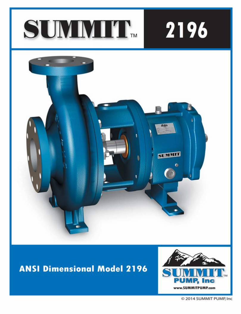
EC / EU Declaration of ConformityThe objective of the declaration described is in conformity with the relevant Union harmonisation
legislation: Directive 94/9/EC (until April 19, 2016) and Directive 2014/34/EU (from April 20, 2016).
The harmonised standards have been compared to the applicable standards used for certification purposes and no changes in the state of the art technical knowledge apply to the listed equipment.
AODD Pumps and Surge SuppressorsTechnical File No.: 203104000-1410/MER
AODD (Air-Operated Double Diaphragm) PumpsEC Type Examination Certificate No. Pumps: KEMA 09ATEX0071 X
DEKRA Certification B.V. (0344)Meander 10516825 MJ ArnhemThe Netherlands
Applicable Standard:EN13463-1: 2001EN13463-5: 2003EN60079-25: 2004Harmonised Standard:EN13463-1: 2009EN13463-5: 2011EN60079-25:2010
David Roseberry, Director of EngineeringDATE/APPROVAL/TITLE:18 March 2016
Hazardous Locations Applied:I M1 c II 2 G Ex ia c IIC T5II 2 D Ex c iaD 20 IP67 T100°CII 2 G Eex m c II T5II 2 D c IP65 T100°C
II 1 G c T5II 1 D c T100°CII 2 G c T5II 2 D c T100°C
UNIVERSAL ALL SP


Model L3/L3-L Bronze Safety Valves, Low
Lift

Inquiry PREV Favorite
Product Description
Product Description
Product Name:
Model L3 Bronze Safety Valves, With Sealing, Low Lift
Model L3-L Bronze Safety Valves, With Lever, Low Lift
Feature:
1. First jet and blowout almost happen at the same time.
2. Valve disc with fine minor polish has an incredible performance in anti-leakage.

Specification:
Size: 1/2” ~ 2”
Valve Body: Cast Bronze
Valve Seat: Forging Brass
Disc: Forging Brass
Spring: Steel
Stem: Brass
Working Pressure: 0.3-10 kgf/c㎡, 11-20 kgf/c㎡
Working Temp.: -45℃ to 185℃
Working Fluid: Noncorrosive Gas, Air, Steam
Dimensions (Unit:mm)
L3S
Inlet
B
Outlet
C
Valve
Seat
Orifice
D
E
F
Lift Wt.
kg
L3-LS
Wt.
kg
1/2” 138 1/2” 1/2” 13 29 50 0.52 0.52 1/2” 161 0.59
3/4” 150 3/4” 3/4” 19 36 58 0.76 0.66 3/4” 172 0.74
1” 180 1” 1” 25 40 70 1.00 1.09 1” 202 1.19
1-1/4” 206 1-1/4” 1-1/4” 32 50 82 1.28 1.90 1-1/4” 222 1.94
1-1/2” 231 1-1/2” 1-1/2” 38 54 93 1.52 2.35 1-1/2” 246 2.39
2” 265 2” 2” 50 67 102 2.00 3.85 2” 282 4.11
Safety/ Quality Approvals:
ISO 9001 Certificate


Inspired By Challenge
Flanged valves
1

2
Floating Ball Valves
Flanged valves
IntroductionHabonim's rugged flanged valves provide high durability and exceptional performance even under the most extreme conditions. The Habonim line of flanged valves includes end connections that comply with ANSI B16.5 class 150 and class 300 (in both standard port and full port) and EN 1092 (DIN flanged valves) PN16 and PN40 in full port.
Technical summarySize range ½"- 8" (DN15 - DN200)Flange connection 31 series - ANSI 150 Standard port
32 series - ANSI 300 Standard port73 series - ANSI 150 full port74 series - ANSI 300 full port77 series - DIN PN16 full port78 series - DIN PN40 full port
Pressure range Vacuum 10-6 Tor to 50 bar (750 psi)Temperature range -60 °C to +260 °C (-76 °F to +500 °F)Materials Stainless steel A351 CF8M, carbon steel A216 WCB, bronze, alloy C22, alloy C276, duplex, super
duplex, 254SMO, inconel 625, monel 400 and more End connections FlangedOperation Lever or gear operated, pneumatic or electric actuatedService Chemical, petrochemical, oil and gas, energy, pulp & paper and others
Standards of complianceFactory certification ISO 9001-2008 Quality management systemValve design and tests ANSI B16.34, API 6D / ISO 14313,
ISO 17292Valve design
ANSI B16.5, EN 1092 Pt 1&2 Flange dimensionsANSI B16.10, EN 558 Face-to-Face dimensionsNACE MR-0175, ISO 15156-1/2/3 Materials for use in H2S-containing environments in oil and
gas production
EN 12266-1, API 598 Testing of metallic valves - Pressure tests, test procedures and acceptance criteria.
Certifications API 607, ISO 10497 Testing of valves - Fire type-testing requirementsISO 15848-1 Industrial valves - measurement, test and qualification
procedures for fugitive emissions
PED 97/23/EC Module H Pressure equipment directiveATEX 94/9/EC Equipment and protective systems intended for use in
potentially explosive atmospheres (optional for actuated unit only)
IEC 61508-2 SIL 2/3 Safety integrity level - Functional safety of electrical/electronic/programmable electronic safety-related systems (optional for actuated unit only)
Documentation EN 10204 2.2 / 3.1 / 3.2 Metallic materials - types of inspection documents
Flanged valves General HermetiX™ HermetiX™ Fire-safe
HermetiX™Graphite-free fire-safe
Ordering code system

3
Flanged valves
Flanged valves
General
Design features
Body• One-and two-piece valve design• Cast body-flange connection• Full compliance with ASME B16.34 and API 6D• Spiral groove flange face to 3.2-6.3 Ra• Tongue and groove design for DIN flanges as per EN1092
Pt. 1&2 or Russian GOST standard GOST 12815-80 • Top mounting platform compliant with ISO 5211 for easy
mounting of actuator and other accessories• Carbon steel valves are phosphate to MIL-DTL-13924D
standard or available in epoxy paint finish upon request• Stainless steel and high alloy valves provided with
natural finish• Steam jacket - upon request
Ball • Mirror polished solid ball• Pressure equalizing hole in the stem slot• Variety of materials and designs
Stem• One-piece solid stem• Blowout-proof design• Antistatic device • Fire-lip
HermetiX™ stem seal• ISO 15848-1 certified• High endurance up to 500 cycles• Graphite-free fire-safe certified stem seal• Anti-abrasion mechanism• Live loaded
Seats and seals• Flexible seat design • Reduced wear • Low torque• Rate A leakage tightness• Self-relief seat (SRS) - upon request• Variety of materials and designs
Seats
BodyBall
HermetiX™ stem seal
Body sealStemCF PEEK thrust seal

ø Ball port
A
H
B
DC
S
ø W
TxL threadF PCD
Preparationfor actuation
M
N thread
PP
Stem flatsshow valveball position
½”without nut
¾" - 2”with nut
1
35
66A
5
7
4
2021
17
15
13
16
8
14
12
10
9
11
7a
2
6
Floating Ball Valves
Flanged valves
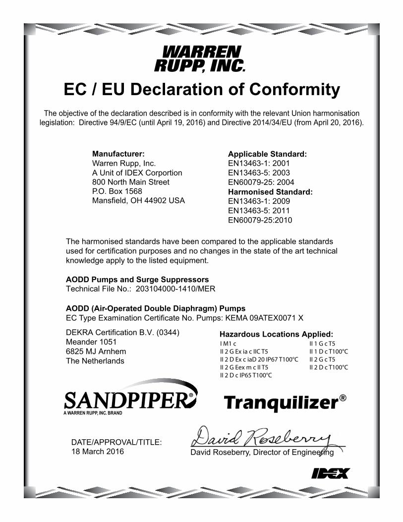
Valve dimensions
Size 1⁄2”-2” | DN15-DN50 | ANSI Class 150/300 | 31X/32X, 31P(1)/32P(1) Series
Std. port Unit Ball
portA
B C D H S W
M N P F TxLWeight kg/lb Kv
150 300 150 300 150 300 Cv
DN15 mm 11.15 108.00 140.00 46.00 29.00 38.00 92.00 151.00 88.90 95.25 5.54 3/8 -24 UNF-2A
11.10 (F03) 36.00M5x10
1.70 2.40 71/2” inch 0.44 4.25 5.50 1.81 1.14 1.50 3.62 5.94 3.50 3.75 0.22 0.43 1.42 3.80 5.30 8
DN20 mm 14.30 117.00 152.00 49.00 31.40 40.30 94.00 151.00 98.55 163.07 5.54 3/8 -24 UNF-2A
11.10 (F03) 36.00M5x10
2.30 3.30 103/4” inch 0.56 4.61 6.00 1.93 1.24 1.59 3.70 5.94 3.88 6.42 0.21 0.43 1.42 5.10 7.30 12
DN25 mm 20.60 127.00 165.00 57.00 38.20 55.60 103.50 170.00 107.95 123.95 7.54 7/16 -20 UNF-2A
15.40 (F04) 42.00M5x10
3.10 4.60 27
1" inch 0.81 5.00 6.50 2.25 1.50 2.19 4.07 6.69 4.25 4.88 - 0.60 1.65 7.30 10.20 32
DN40 mm 31.80 165.00 190.00 62.00 43.60 73.10 119.20 220.50 127.00 155.52 8.70 9/16 -18 UNF-2A
19.60 (F05) 50.00M6x12
5.50 8.70 70
11/2” inch 1.25 6.50 7.50 2.44 1.72 2.88 4.70 8.68 5.00 6.10 0.34 0.77 1.97 12.20 19.30 82
DN50 mm 38.20 178.00 216.00 68.00 48.30 77.80 123.90 220.50 152.40 165.10 8.70 9/16 -18 UNF-2A
19.60 (F05) 50.00M6x12
8.10 10.80 103
2" inch 1.50 7.00 8.50 2.67 1.90 3.06 4.88 8.68 6.00 6.50 0.34 0.77 1.97 18.00 24.00 120
Flanged valves General HermetiX™ HermetiX™ Fire-safe
HermetiX™Graphite-free fire-safe
Ordering code system

ø Ball port
A
H
B
DC
S
ø W
TxL threadF PCD
Preparationfor actuation
M
N thread
PP
Stem flatsshow valveball position
½”without nut
¾" - 2”with nut
1
35
66A
5
7
4
2021
17
15
13
16
8
14
12
10
9
11
7a
2
7
Flanged valves
Flanged valves
Components & materials
Item Description Material specification Qty.
7* Stem thrust seal PEEK, CF PEEK, PCTFE (KEL-F), TFM (2), CF PTFE (2) 17a** Anti-abrasion ring PEEK, CF PEEK, PCTFE (KEL-F), TFM (2), CF PTFE (2) 18 Stop pin A582 303 19* Stem seal CF PTFE, TFM, Graphite (2) 110 Follower B783 316L, B164 N04400 111 Disc spring A693 631 17-7PH 212 Stem nut A194 8M, EN3506-2 A4-80 113 Locking clip A164 8, 8A 114 Handle C.St. A29 G10200 Zinc plate, A240 430 115 Serrated washer A194 6 116 Handle nut A194 8M, EN3506-2 A4-80 117 Sleeve PVC 120 Antistatic spring A313 302 121 Antistatic plunger A479 304 123 Tag (not shown) A167 304 1
* Repair kit components** Only with HermetiX™ stem seal- Only with graphite body seal
Item Description Material specification Qty.
1Body A351 CF8M, A216 WCB, A351 CN7M, A494
M-35-1, A494 CW-12MW, A494 CX-2MW, A351 CK3MCuN, A995 CD3MN 4A, A995 CE3MN 5A
1
2Plug A351 CF8M, A216 WCB, A351 CN7M, A494
M-35-1, A494 CW-12MW, A494 CX-2MW, A351 CK3MCuN, A995 CD3MN 4A, A995 CE3MN 5A
1
3Ball A351 CF8M, B473 N08020, B164 N04400, B574
N06022, B574 N10276, A479 S31254, A479 S31803, A479 S32750
1
4Stem A479 316L, A564 Gr 630 H1150D 17-4PH, B473
N08020, B164 N04400, B574 N06022, B574 N10276, A479 S31254, A479 S31803, A479 S32750
1
5* Seat PTFE, RPTFE, CF PTFE, PEEK, CF PEEK, TFM, UHMWPE, VESPEL, PVDF, DELRIN, PCTFE (KEL-F) 2
6* Body seal PTFE, RPTFE, TFM, UHMWPE, Graphite 1
6A-Support ring A479 316L, B473 N08020, B164 N04400, B574
N06022, B574 N10276, A479 S31254, A479 S31803, A479 S32750
1
Size 1⁄2”-2” | DN15-DN50 | ANSI Class 150/300 | 31X/32X, 31P(1)/32P(1) Series
(1) 31P/32P Series is Habonim's standard valve design without the HermetiX™ stem seal construction.
(2) This material can only be used as part of the 31P/32P design.

ø W
TxL threadF PCD
C
H
S
D
B
A
ø Ball port
Preparationfor actuation
M
N thread
PP
Stem flatsshow valveball position
½”without nut
¾" - 1”with nut
15
13
16
8
14
17
12
10
9
11
7a
1
3
5
6
2
5
7
4
2021
10
Floating Ball Valves
Flanged valves
Valve dimensions
Size 1⁄2”-1” | DN15-DN25 | ANSI Class 150/300 | 73X/74X, 73P(1)/74P(1) Series
Std. port Unit Ball
portA
B C D H SØW
M N P F TxLWeight kg/lb Kv
150 300 150 300 150 300 Cv
DN15 mm 14.30 108.00 140.00 47.00 31.40 40.50 94.00 151.00 89.00 95.00 5.54 3/8 -24 UNF-2A
11.10 (F03)36.00M5x10
1.80 2.30 261/2" inch 0.56 4.25 5.51 1.85 1.24 1.59 3.70 5.95 3.50 3.74 0.22 0.44 1.42 4.00 5.10 30
DN20 mm 20.60 117.00 152.00 57.00 38.20 55.60 103.50 170.00 98.00 117.00 7.54 3/8 -24 UNF-2A
15.40 (F04)42.00M5x10
2.20 3.30 433/4” inch 0.81 4.61 5.98 2.24 1.50 2.19 4.08 6.69 3.86 4.61 0.30 0.61 1.65 4.80 7.30 50
DN25 mm 25.40 127.00 165.00 62.00 42.70 60.30 108.00 170.00 108.00 124.00 7.54 7/16 -20 UNF-2A
15.40 (F04)42.00M5x10
3.20 4.60 85
1" inch 1.00 5.00 6.50 2.44 1.68 2.37 4.25 6.69 4.25 4.88 0.30 0.61 1.65 7.00 10.10 100
Flanged valves General HermetiX™ HermetiX™ Fire-safe
HermetiX™Graphite-free fire-safe
Ordering code system

ø W
TxL threadF PCD
C
H
S
D
B
A
ø Ball port
Preparationfor actuation
M
N thread
PP
Stem flatsshow valveball position
½”without nut
¾" - 1”with nut
15
13
16
8
14
17
12
10
9
11
7a
1
3
5
6
2
5
7
4
2021
11
Flanged valves
Flanged valves
Components & materials
Size 1⁄2”-1” | DN15-DN25 | ANSI Class 150/300 | 73X/74X, 73P(1)/74P(1) Series
Item Description Material specification Qty.
7a** Anti-abrasion ring PEEK, CF PEEK, PCTFE (KEL-F), TFM (2), CF PTFE (2) 18 Stop pin A582 303 19* Stem seal CF PTFE, TFM, Graphite (2) 110 Follower B783 316L, B164 N04400 111 Disc spring A693 631 17-7PH 212 Stem nut A194 8M, EN3506-2 A4-80 113 Locking clip A164 8, 8A 114 Handle C.St. A29 G10200 Zinc plate, A240 430 115 Serrated washer A194 6 116 Handle nut A194 8M, EN3506-2 A4-80 117 Sleeve PVC 120 Antistatic spring A313 302 121 Antistatic plunger A479 304 123 Tag (not shown) A167 304 1
* Repair kit components** Only with HermetiX™ stem seal
Item Description Material specification Qty.
1Body A351 CF8M, A216 WCB, A351 CN7M, A494
M-35-1, A494 CW-12MW, A494 CX-2MW, A351 CK3MCuN, A995 CD3MN 4A, A995 CE3MN 5A
1
2Insert A351 CF8M, A216 WCB, A351 CN7M, A494
M-35-1, A494 CW-12MW, A494 CX-2MW, A351 CK3MCuN, A995 CD3MN 4A, A995 CE3MN 5A
1
3Ball A351 CF8M, B473 N08020, B164 N04400,
B574 N06022, B574 N10276, A479 S31254, A479 S31803, A479 S32750
1
4
Stem A479 316L, A564 Gr 630 H1150D 17-4PH, B473 N08020, B164 N04400, B574 N06022, B574 N10276, A479 S31254, A479 S31803, A479 S32750
1
5* Seat PTFE, RPTFE, CF PTFE, PEEK, TFM, UHMWPE, VESPEL, PVDF, DELRIN, PCTFE (KEL-F)
2
6* Body seal PTFE, RPTFE, TFM, UHMWPE, Graphite 17* Stem thrust seal PEEK, CF PEEK, PCTFE (KEL-F), TFM (2), CF PTFE (2) 1
(1) 73P/74P Series is Habonim's standard valve design without the HermetiX™ stem seal construction.
(2) This material can only be used as part of the 73P/74P design.

ø W
TxL threadF PCD
C
H
S
D
BA
ø Ball port
N thread
Preparationfor actuation
M
PP
Stem flatsshow valveball position
2"without nut
1½"with nut
17
15
13
16
8
14
12
10
9
11
7a
1
3
5
6
2
5
7
4
2021
18
19
12
Floating Ball Valves
Flanged valves
Valve dimensions
Size 11⁄2”-2” | DN40-DN50 | ANSI Class 150/300 | 73X/74X, 73P(1)/74P(1) Series
Std. port Unit Ball
portA B
C D H SØW
M N P F TxLWeight kg/lb Kv
150 300 150 300 150 300 150 300 Cv
DN40 mm 38.10 165.00 190.00 97.00 110.00 48.30 77.80 124.00 220.50 127.00 156.00 8.7 9/16 -18 UNF-2A
19.6 (F05) 50.00M6x12
6.60 9.80 214
11/2” inch 1.50 6.50 7.50 3.82 4.33 1.90 3.06 4.88 6.68 5.00 6.14 0.34 0.77 1.97 14.50 21.50 250
DN50 mm 50.00 178.00 216.00 109.00 141.00 70.00 88.00 134.20 220.50 152.00 165.00 8.7 9/16 -18 UNF-2A
19.6 (F07) 70.00M8x12
13.00 15.00 410
2" inch 2.00 7.00 8.50 4.29 5.55 2.75 3.46 5.28 6.68 5.98 6.50 0.34 0.77 2.76 28.60 33.00 480
Flanged valves General HermetiX™ HermetiX™ Fire-safe
HermetiX™Graphite-free fire-safe
Ordering code system

ø W
TxL threadF PCD
C
H
S
D
BA
ø Ball port
N thread
Preparationfor actuation
M
PP
Stem flatsshow valveball position
2"without nut
1½"with nut
17
15
13
16
8
14
12
10
9
11
7a
1
3
5
6
2
5
7
4
2021
18
19
13
Flanged valves
Flanged valves
Components & materials
Size 11⁄2”-2” | DN40-DN50 | ANSI Class 150/300 | 73X/74X, 73P(1)/74P(1) Series
Item Description Material specification Qty.
8 Stop pin A582 303 19* Stem seal CF PTFE, TFM, Graphite (2) 110 Follower B783 316L, B164 N04400 111 Disc spring A693 631 17-7PH 212 Stem nut A194 8M, EN3506-2 A4-80 113 Locking clip A164 8, 8A 114 Handle C.St. A29 G10200 Zinc plate, A240 430 115 Serrated washer A194 6 116 Handle nut A193 B8, B8A 117 Sleeve PVC 118 Body bolts A193 B8, EN3506-1 A2-70 419 Body nuts A194 8M, EN3506-2 A4-80 420 Antistatic spring A313 302 121 Antistatic plunger A479 304 123 Tag (not shown) A167 304 1
* Repair kit components** Only with HermetiX™ stem seal
Item Description Material specification Qty.
1Body A351 CF8M, A216 WCB, A351 CN7M, A494
M-35-1, A494 CW-12MW, A494 CX-2MW, A351 CK3MCuN, A995 CD3MN 4A, A995 CE3MN 5A
1
2End A351 CF8M, A216 WCB, A351 CN7M, A494
M-35-1, A494 CW-12MW, A494 CX-2MW, A351 CK3MCuN, A995 CD3MN 4A, A995 CE3MN 5A
1
3Ball A351 CF8M, B473 N08020, B164 N04400,
B574 N06022, B574 N10276, A479 S31254, A479 S31803, A479 S32750
1
4
Stem A479 316L, A564 Gr 630 H1150D 17-4PH, B473 N08020, B164 N04400, B574 N06022, B574 N10276, A479 S31254, A479 S31803, A479 S32750
1
5* Seat PTFE, RPTFE, CF PTFE, PEEK, TFM, UHMWPE, VESPEL, PVDF, DELRIN, PCTFE (KEL-F)
2
6* Body seal PTFE, RPTFE, TFM, UHMWPE, Graphite 17* Stem thrust seal PEEK, CF PEEK, PCTFE (KEL-F), TFM (2), CF PTFE (2) 17a** Anti-abrasion ring PEEK, CF PEEK, PCTFE (KEL-F), TFM (2), CF PTFE (2) 1
(1) 73P/74P Series is Habonim's standard valve design without the HermetiX™ stem seal construction.
(2) This material can only be used as part of the 73P/74P design.

S
CD
BA
H
ø W
ø Ball port
TxL threadF PCD
M
N thread
P
Stem flatsshow valveball position
½" - 1”
Preparationfor actuation
7
4
2021
35
6
2
5
1
15
13
16
8
14
17
12
10
9
11
7a
16
Floating Ball Valves
Flanged valves
Valve dimensions
Size 1⁄2”-1” | Class DN15-DN25 | DIN PN40 | 78X, 78P(1) Series
Std. port Unit Ball
portA
B C D H M N P S ØW F TxLWeight kg/lb Kv
F1 F4 F1 F4 Cv
DN15 mm 14.30 130.00 115.00 48.00 31.50 40.50 98.60 5.54 3/8 -24 UNF-2A
11.10 160.00 95.00 (F03)36.00M5x10
2.20 2.10 261/2” inch 0.56 5.12 4.53 1.89 1.24 1.59 3.88 0.22 0.44 6.30 3.74 1.42 4.80 4.60 30
DN20 mm 20.60 150.00 120.00 58.00 38.30 56.50 105.00 7.54 7/16 -20 UNF-2A
15.40 170.00 105.00 (F04)42.00M5x10
3.20 3.00 433/4” inch 0.81 5.91 4.72 2.28 1.51 2.22 4.13 0.30 0.61 6.69 4.13 1.65 7.00 6.60 50
DN25 mm 25.40 160.00 125.00 63.50 41.80 61.00 108.00 7.54 7/16 -20 UNF-2A
15.40 170.00 115.00 (F04)42.00M5x10
4.20 4.00 85
1" inch 1.00 6.30 4.92 2.50 1.65 2.40 4.25 0.30 0.61 6.69 4.53 1.65 9.20 8.80 100
Flanged valves General HermetiX™ HermetiX™ Fire-safe
HermetiX™Graphite-free fire-safe
Ordering code system

S
CD
BA
H
ø W
ø Ball port
TxL threadF PCD
M
N thread
P
Stem flatsshow valveball position
½" - 1”
Preparationfor actuation
7
4
2021
35
6
2
5
1
15
13
16
8
14
17
12
10
9
11
7a
17
Flanged valves
Flanged valves
Components & materials
Size 1⁄2”-1” | Class DN15-DN25 | DIN PN40 | 78X, 78P(1) Series
Item Description Material specification Qty.
7* Stem thrust seal PEEK, CF PEEK, PCTFE (KEL-F), TFM (2), CF PTFE (2) 17a** Anti-abrasion ring PEEK, CF PEEK, PCTFE (KEL-F), TFM (2), CF PTFE (2) 18 Stop pin NiCr19NbMo (2.4668) 19* Stem seal CF PTFE, TFM, Graphite (2) 110 Follower B783 316L, B164 N04400 111 Disc spring A693 631 17-7PH 212 Stem nut A194 8M, EN3506-2 A4-80 113 Locking clip A164 8, 8A 114 Handle C.St. A29 G10200 Zinc plate, A240 430 115 Serrated washer A194 6 116 Handle nut A194 8M, EN3506-2 A4-80 117 Sleeve PVC 120 Antistatic spring A313 302 121 Antistatic plunger A479 304 123 Tag (not shown) A167 304 1
* Repair kit components** Only with HermetiX™ stem seal
Item Description Material specification Qty.
1
Body X 2 CrNiMo 17 13 2 (1.4404), GS-C25 (DIN1.0619), NiCr20CuMo (2.4660), NiCu30Fe (2.4360), NiCr16Mo15W(2.4819), NiCr21Mo14W(2.4602), X1CrNiMoCuN20-18-7 (1.4547), X2CrNiMoN 22-5-3 (1.4462), X2CrNiMoN25-7-4 (1.4410)
1
2
Plug X 2 CrNiMo 17 13 2 (1.4404), GS-C25 (DIN1.0619), NiCr20CuMo (2.4660), NiCu30Fe (2.4360), NiCr16Mo15W(2.4819), NiCr21Mo14W(2.4602), X1CrNiMoCuN20-18-7 (1.4547), X2CrNiMoN 22-5-3 (1.4462), X2CrNiMoN25-7-4 (1.4410)
1
3Ball A351 CF8M, B473 N08020, B164 N04400, B574
N06022, B574 N10276, A479 S31254, A479 S31803, A479 S32750
1
4Stem A479 316L, A564 Gr.630 H1150D 17-4PH, B473
N08020, B164 N04400, B574 N06022, B574 N10276, A479 S31254, A479 S31803, A479 S32750
1
5* Seat PTFE, RPTFE, CF PTFE, PEEK, TFM, UHMWPE, VESPEL, PVDF, DELRIN, PCTFE (KEL-F)
2
6* Body seal PTFE, RPTFE, TFM, UHMWPE, Graphite 1(1) 78P Series is Habonim's standard valve design without the HermetiX™
stem seal construction.(2) This material can only be used as part of the 78P design.
TxL threadF PCD
ø W
S
H
C
B
A
ø Ball port
D
Preparationfor actuation
M
N thread
PP
Stem flatsshow valveball position
2"without nut
1½"with nut
1
12
10
9
11
15
13
16
3
5
6
2
5
8
14
19
18
17
7a
7
4
2021
18
Floating Ball Valves
Flanged valves
Valve dimensions
Size 11⁄2”-2” | DN40-DN50 | DIN PN40 | 78X, 78P(1) Series
Std. port Unit Ball
port
AC B D H S ØW M N P F TxL
Weight kg/lb Kv
150 300 F1, F5 PN40 F4 PN40 Cv
DN40 mm 38.10 200.00 140.00 48.30 65.90 77.80 124.00 122.00 150.00 8.70 9/16 -18 UNF-2A
19.60 (F05) 50.00M6x12
10.90 10.30 214
11/2” inch 1.50 7.87 5.51 1.90 2.59 3.06 4.88 4.81 5.91 0.34 0.77 1.97 24.00 22.70 250
DN50 mm 50.00 230.00 150.00 78.00 60.70 119.00 137.30 240.00 165.00 8.70M16
11.00 (F07) 70.00M8x12
15.00 13.00 410
2" inch 2.00 9.06 5.91 3.07 2.39 4.69 5.41 9.45 6.50 0.34 0.43 2.76 33.00 28.60 480
Flanged valves General HermetiX™ HermetiX™ Fire-safe
HermetiX™Graphite-free fire-safe
Ordering code system

TxL threadF PCD
ø W
S
H
C
B
A
ø Ball port
D
Preparationfor actuation
M
N thread
PP
Stem flatsshow valveball position
2"without nut
1½"with nut
1
12
10
9
11
15
13
16
3
5
6
2
5
8
14
19
18
17
7a
7
4
2021
19
Flanged valves
Flanged valves
Components & materials
Size 11⁄2”-2” | DN40-DN50 | DIN PN40 | 78X, 78P(1) Series
Item Description Material specification Qty.
7* Stem thrust seal PEEK, CF PEEK, PCTFE (KEL-F), TFM (2), CF PTFE (2) 17a** Anti-abrasion ring PEEK, CF PEEK, PCTFE (KEL-F), TFM (2), CF PTFE (2) 18 Stop pin A582 303 19* Stem seal CF PTFE, TFM, Graphite (2) 110 Follower B783 316L, B164 N04400 111 Disc spring A693 631 17-7PH 212 Stem nut A194 8M, EN3506-2 A4-80 113 Locking clip A164 8, 8A 114 Handle C.St. A29 G10200 Zinc plate, A240 430 115 Serrated washer A194 6 116 Handle nut A193 B8, B8A 117 Sleeve PVC 118 Body bolts A193 B8, EN3506-1 A2-70 419 Body nuts A194 8M, EN3506-2 A4-80 420 Antistatic spring A313 302 121 Antistatic plunger A479 304 123 Tag (not shown) A167 304 1
* Repair kit components** Only with HermetiX™ stem seal
Item Description Material specification Qty.
1
Body X 2 CrNiMo 17 13 2 (1.4404), GS-C25 (DIN1.0619), NiCr20CuMo (2.4660), NiCu30Fe (2.4360), NiCr16Mo15W(2.4819), NiCr21Mo14W(2.4602), X1CrNiMoCuN20-18-7 (1.4547), X2CrNiMoN 22-5-3 (1.4462), X2CrNiMoN25-7-4 (1.4410)
1
2
End X 2 CrNiMo 17 13 2 (1.4404), GS-C25 (DIN1.0619), NiCr20CuMo (2.4660), NiCu30Fe (2.4360), NiCr16Mo15W(2.4819), NiCr21Mo14W(2.4602), X1CrNiMoCuN20-18-7 (1.4547), X2CrNiMoN 22-5-3 (1.4462), X2CrNiMoN25-7-4 (1.4410)
1
3Ball A351 CF8M, B473 N08020, B164 N04400, B574
N06022, B574 N10276, A479 S31254, A479 S31803, A479 S32750
1
4Stem A479 316L, A564 Gr 630 H1150D 17-4PH, B473
N08020, B164 N04400, B574 N06022, B574 N10276, A479 S31254, A479 S31803, A479 S32750
1
5* Seat PTFE, RPTFE, CF PTFE, PEEK, TFM, UHMWPE, VESPEL, PVDF, DELRIN, PCTFE (KEL-F)
2
6* Body seal PTFE, RPTFE, TFM, UHMWPE, Graphite 1(1) 78P Series is Habonim's standard valve design without the HermetiX™
stem seal construction.(2) This material can only be used as part of the 78P design.