T61 Smart Modem
Hardware User Guide V1.3
Supporting: Firmware Version: V20017 Model: T61-EHS5 T61-BGS2
Date: 2014-07-21

Copyright 2014, TCAM Technology Pte Ltd. All Rights Reserved.
This document (T61 Smart Modem Hardware User Guide) contains information that is proprietary to TCAM Technology Pte Ltd. No part of this document may be copied, or reproduced in any form or by any means, or transferred to any third party without prior written consent of TCAM Technology Pte Ltd. The content of this document may be revised without prior notice.
T61 Smart Modem Page 3 of 53 Hardware User Guide V1.3
Contents 1 Introduction ................................................................................................................................. 5
1.1 Related Documents ...................................................................................................................... 5
1.2 Product Label ............................................................................................................................... 5
1.3 Certification Test .......................................................................................................................... 6
2 Device Overview ........................................................................................................................... 7
2.1 Key Specification at a glance ......................................................................................................... 7
2.2 Block Diagram .............................................................................................................................. 9
3 Special Features ......................................................................................................................... 10
3.1 Dual IP Connection ..................................................................................................................... 10
3.2 Self-Recovery ............................................................................................................................. 10
3.3 DDNS IP Update .......................................................................................................................... 11
3.4 Schedule to Connect ................................................................................................................... 11
4 Hardware Interface Description .................................................................................................. 12
4.1 Overview .................................................................................................................................... 12
4.2 Interface Variant ........................................................................................................................ 13
4.3 4-Pin Micro-Fit Interface ............................................................................................................. 14
4.4 SIM Interface .............................................................................................................................. 14
4.5 Status LED .................................................................................................................................. 15
4.6 Antenna Interface....................................................................................................................... 15
5 Mechanics, Mounting and Packaging .......................................................................................... 16
5.1 Mechanical Dimensions .............................................................................................................. 16
5.2 Mounting T61 Smart Modem ...................................................................................................... 17
5.3 Packaging ................................................................................................................................... 17
6 Get Started ................................................................................................................................. 19
6.1 Box Open .................................................................................................................................... 19
7 Device Configuration .................................................................................................................. 20
7.1 Initial Setup ................................................................................................................................ 20
7.2 Switching Between Smart Modem Mode and Normal Modem Mode ......................................... 23
7.2.1 Switch to Normal Modem Mode ............................................................................................ 23
7.2.2 Switch to Smart Modem Mode .............................................................................................. 26
7.3 Smart Modem Configuration ...................................................................................................... 27
7.3.1 General Guidelines for Smart Modem Configuration.............................................................. 27
7.3.2 Mobile Network Operator (MNO) .......................................................................................... 29
T61 Smart Modem Page 4 of 53 Hardware User Guide V1.3
7.3.3 T61 Device Information ......................................................................................................... 30
7.3.4 Data Service Center (DSC) ...................................................................................................... 32
7.3.5 Command Service Center (CSC) ............................................................................................. 34
7.3.6 Schedule to Connect Settings ................................................................................................ 35
7.3.7 Serial Port Setup .................................................................................................................... 36
7.3.8 Recovery Setup ...................................................................................................................... 38
7.3.9 I/O Setup ............................................................................................................................... 40
7.3.10 Utilities ............................................................................................................................... 42
7.4 Default Settings .......................................................................................................................... 43
7.5 SMS Functions ............................................................................................................................ 44
8 Migration from TMA-M37i, TMA-M55i and TMN-51T ................................................................. 45
8.1 Normal Modem Mode ................................................................................................................ 45
8.2 Smart Modem ............................................................................................................................ 45
9 Application Notes ....................................................................................................................... 47
9.1 T61 Firmware Update ................................................................................................................. 47
9.1.1 Direct Wire Firmware Update ................................................................................................ 47
9.1.2 Firmware Update Over-The-Air .............................................................................................. 48
9.2 T61 Digital Input Configuration ................................................................................................... 49
9.2.1 Connection ............................................................................................................................ 49
9.2.2 Configuration ........................................................................................................................ 49
9.2.3 Testing 49
9.3 T61 SMS Features ....................................................................................................................... 50
9.3.1 Reset T61 .............................................................................................................................. 50
9.3.2 Turn ON Digital Output .......................................................................................................... 50
9.3.3 Turn OFF Digital Output ......................................................................................................... 50
9.3.4 Configure Server IP and Port .................................................................................................. 51
9.4 T61 Schedule to Connect ............................................................................................................ 51
9.4.1 Start a Connection ................................................................................................................. 51
9.4.2 End of a Connection .............................................................................................................. 52
9.4.3 “Sleeping” Mode ................................................................................................................... 52
T61 Smart Modem Page 5 of 53 User Guide V1.2
1 Introduction This document explains the hardware related features and functionalities of T61 Smart Modem. It
can be applied to all variants of T61 models with minimum differences. The scope of this documents
includes a brief device overview, detailed feature description, step-by-step device configuration
tutorial.
1.1 Related Documents
[1] T61 Smart Modem Hardware User Guide
[2] T61 Normal Modem PC Setup Manual
[3] Centre Manager User Guide
[4] Cinterion® BGS2-W AT Command Set 01.301
[5] Cinterion® EHS5-E AT Command Set 02.000
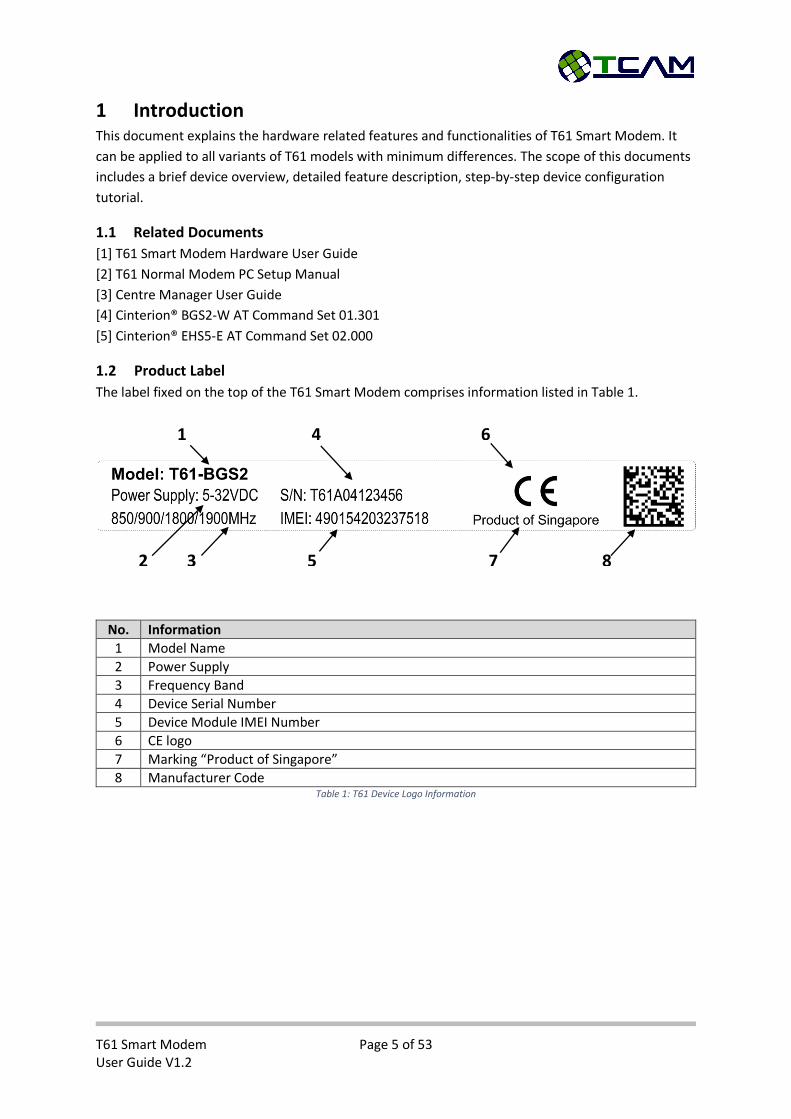
1.2 Product Label
The label fixed on the top of the T61 Smart Modem comprises information listed in Table 1.
No. Information
1 Model Name
2 Power Supply
3 Frequency Band
4 Device Serial Number
5 Device Module IMEI Number
6 CE logo
7 Marking “Product of Singapore”
8 Manufacturer Code Table 1: T61 Device Logo Information
1
2 3
4
5
6
7 8
T61 Smart Modem Page 6 of 53 User Guide V1.2
1.3 Certification Test
T61 is certified for Safety, Emission, ESD, Immunity, RF, EMC, Water/Dust Proof etc, according to the follow standard:
EN60950-1:2006+A11:2009+A1:2010+A12:2011+AC:2011 EN55022:2010/AC:2011 EN55024:2010 EN61000-3-2:2006 + A1:2009+A2:2009 EN61000-3-3:2008 EN62311:2008 EN301 489-7 V1.3.1 (2005-11) EN301 489-1 V1.9.2 (2011-09) EN301 489-24 V1.5.1 (2010-10) EN301 511 V9.0.2 (2003-03) EN301 908-1 V5.2.1 (2011-05) EN301 908-2 V5.2.1 (2011-07) IEC60529:2013 – IP51 Water-proof and Dust Proof
T61 Smart Modem Page 7 of 53 User Guide V1.2
2 Device Overview T61 is a smart gateway connecting serial devices with RS232 or RS485 interfaces to GSM/GPRS/HSPA
network. It is integrated with a 32bit ARM Cortex-M0+ core processor and a Gemalto 2G or 3G
modem module. Equipped with comprehensive features, T61 smart gateway provides industrial
standard flexibility, scalability and data reliability.
T61 Smart Modem has two operation modes, namely Normal Modem Mode and Smart Modem
Mode. In Normal Modem Mode, T61 functions as a standard 2G or 3G modem by providing a direct
serial access to a Gemalto BGS2 or EHS5 module. User could send AT command to achieve various
functions, such as SMS, GSM/GPRS/3G connections for data transfer. In Smart Modem Mode, T61
provides a transparent channel from remote end devices to their dedicated data centers. It can be
configured as server or client, accept SIM card with dynamic IP or static IP, support TCP/UDP,
schedule to connect, connect on demand or “always on” connection, and with Auto Recovery, Re-
connection and Redundancy mechanisms.
As compare to PSTN or GSM dial up line or lease line, T61 smart gateway allows you to migrate your
remote device from traditional serial communication system to the advance GPRS or 3G link,
without tedious application development or in depth knowledge of AT command or GPRS/3G. You
can view this device as the “virtual serial wire over the air”, that links all your remote equipment to
the central PC. It can be a full transparent, protocol independent gateway, used for AMR, SCADA,
general remote monitoring, control and data exchange applications. It is designed for mission critical
industrial applications.
Two operation modes:
Normal Modem: The Data Terminal Equipment (DTE, such as PC, PLC, energy meters,
controller etc.) is intelligent and can issue various AT commands to T61 normal modem as
DCE (Data Communication Equipment) to establish SMS send /receive, GSM/GPRS/HSPA dial
up connection etc.
Smart Modem: In this mode, T61 Smart Modem can be configured with all essential
parameters to manage connections. It connects to assigned data centre server automatically
upon power up and sets up a transparent serial-to-wireless communication channel
between remote devices and data centre. During operation, T61 Smart Modem can maintain
the wireless connection and re-establish connection to data centre server in case of
connection lost. It can monitor site conditions or connections status, such as signal strength,
online/offline etc. It shall be an easy retro-fit solution for existing wired system to 2G/3G
mission critical wireless system.
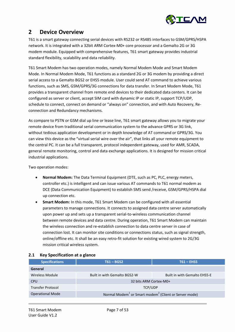
2.1 Key Specification at a glance
Specifications T61 – BGS2 T61 – EHS5
General
Wireless Module Built in with Gemalto BGS2-W Built in with Gemalto EHS5-E
CPU 32 bits ARM Cortex-M0+
Transfer Protocol TCP/UDP
Operational Mode Normal Modem1 or Smart modem
2 (Client or Server mode)

T61 Smart Modem Page 8 of 53 User Guide V1.2
SIM card 1.8V/3V, dynamic or static IP
Internet Connections Primary : Data line
Secondary : Command line
Data logging memory* 3M Bytes
RF Specifications
Frequency Band GSM/GPRS 850/900/1800/1900MHz GSM/GPRS/EDGE 900/1800MHz UMTS/HSPA 900/2100MHz
Output Power 2W for GSM 850/900MHz
1W for GSM 1800/1900MHz
2W for GSM/GPRS/EDGE 900MHz 1W for GSM/GPRS/EDGE 1800MHz
0.25W for UMTS/HSPA (900/2100MHz)
GPRS Multi-slot 10 (quad band) Full PBCCH support
Mobile Station Class B
Coding Scheme 1 – 4
Multi-slot class 12 Full PBCCH support
Mobile Station Class B
Coding Scheme 1 – 4
Data Rate DL: max. 85.6 kbps, UL: max. 42.8 kbps DL: Up to 174kbps, UL: Up to 174 kbps
Antenna Interface SMA Female 50ohm
Serial Specification
Electrical Standard RS232 (DB9 Pin 1,2,3,4,5,7,8) or RS485 (Pin 6,9)
Connector type DB9 Female
Baud Rate RS232: 300 –
230400bps
RS485: 300 –
115200bps
RS232: 300 –
921600bps
RS485: 300 –
115200bps
Flow Control None or
Hardware RTS, CTS, DTR, DCD (RS232 only)
None or
Hardware RTS, CTS, DTR, DCD (RS232 only)
Other Interfaces
DI / AI 1 x DI or AI Configurable
DO 1 x DO open collector, max rating 1A, 48VDC
Status LED 3mm Red
Power Supply
Connector Interface Micro-Fit 3.0- 4pins
Supply Voltage 5-32 VDC
Supply Current (Ave) @5VDC @32VDC @5VDC @32VDC
Idle 50mA 10mA 55mA 10mA
Data Transfer (worst case) 380mA 60mA 850mA 150mA
Mechanical
Enclosure Material Polycarbonate
Dimension
(Enclosure L x W x H)
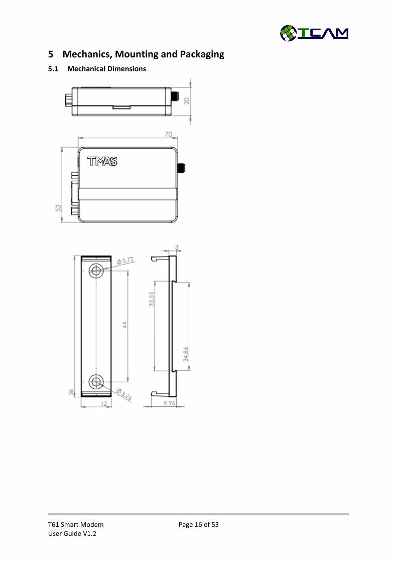
70x53x20mm
Weight 60g
Mounting Clip with Din Rail or screw mounting
Environmental
Operating Temperature -25 to +85 °C
Relative Humidity 90%
Water and Dust Proof IP51
* Features are optional.
T61 Smart Modem Page 9 of 53 User Guide V1.2
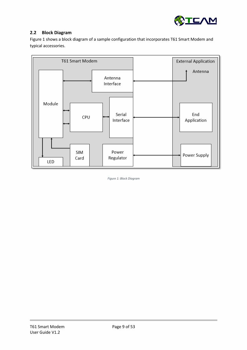
2.2 Block Diagram
Figure 1 shows a block diagram of a sample configuration that incorporates T61 Smart Modem and
typical accessories.
Figure 1: Block Diagram
T61 Smart Modem Page 10 of 53 User Guide V1.2
3 Special Features In this section, some of the new features of T61 Smart Modem are discussed in detail. This is for
better understanding of the device operation in smart modem mode. If your device is utilized in
normal modem mode, please skip this section.
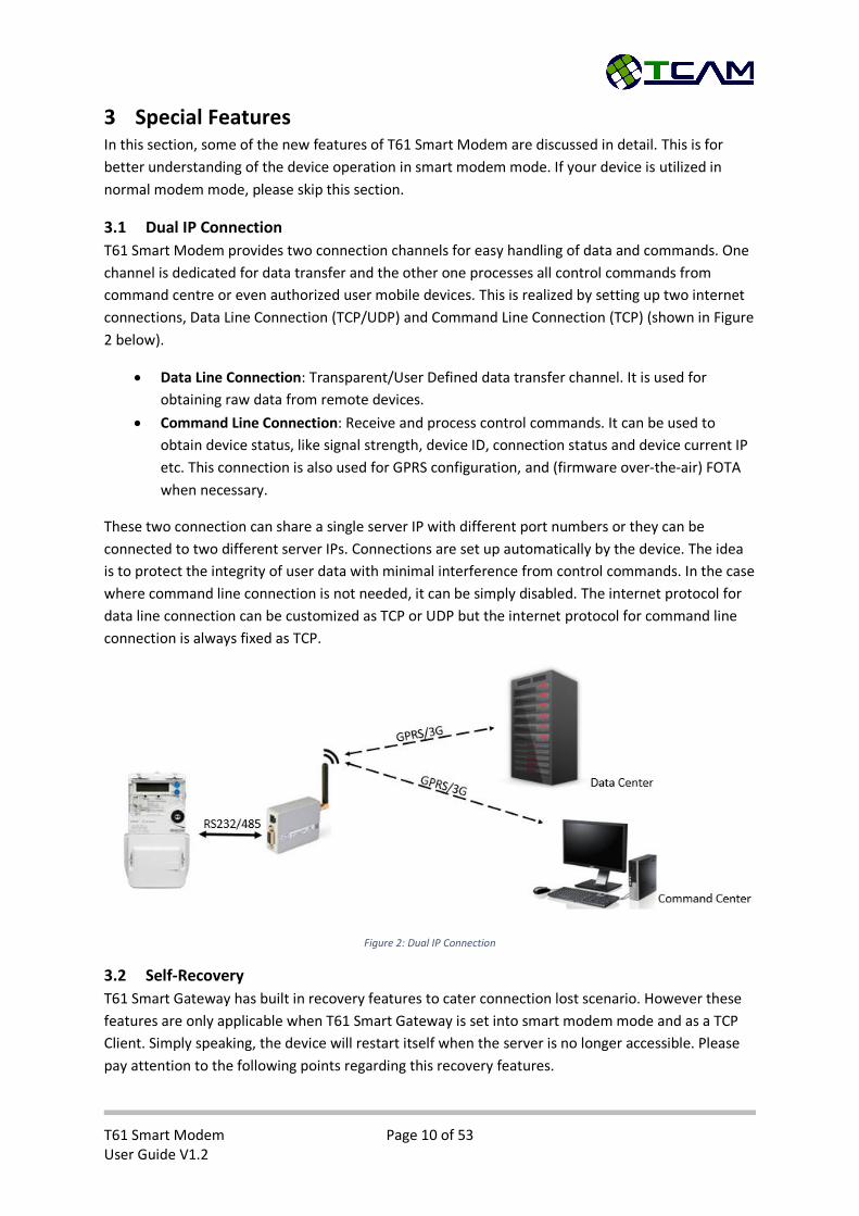
3.1 Dual IP Connection
T61 Smart Modem provides two connection channels for easy handling of data and commands. One
channel is dedicated for data transfer and the other one processes all control commands from
command centre or even authorized user mobile devices. This is realized by setting up two internet
connections, Data Line Connection (TCP/UDP) and Command Line Connection (TCP) (shown in Figure
2 below).
Data Line Connection: Transparent/User Defined data transfer channel. It is used for
obtaining raw data from remote devices.
Command Line Connection: Receive and process control commands. It can be used to
obtain device status, like signal strength, device ID, connection status and device current IP
etc. This connection is also used for GPRS configuration, and (firmware over-the-air) FOTA
when necessary.
These two connection can share a single server IP with different port numbers or they can be
connected to two different server IPs. Connections are set up automatically by the device. The idea
is to protect the integrity of user data with minimal interference from control commands. In the case
where command line connection is not needed, it can be simply disabled. The internet protocol for
data line connection can be customized as TCP or UDP but the internet protocol for command line
connection is always fixed as TCP.
Figure 2: Dual IP Connection
3.2 Self-Recovery
T61 Smart Gateway has built in recovery features to cater connection lost scenario. However these
features are only applicable when T61 Smart Gateway is set into smart modem mode and as a TCP
Client. Simply speaking, the device will restart itself when the server is no longer accessible. Please
pay attention to the following points regarding this recovery features.

T61 Smart Modem Page 11 of 53 User Guide V1.2
Data Line Connection has higher priority. This setting is to safe guard the integrity of user
data communication. Once the device detect the data center is not accessible, it will restart
itself and try to reconnect back to the data center. In the meantime, command line
connection will break due to the reset.
Self-recovery will take effect immediately if connection lost is due to closing Center Manager
or losing GSM/GPRS/3G signal. It may take longer time if the connection lost is due to
abnormal sever shut down (i.e. connection is not properly closed).
3.3 DDNS IP Update
In order to connect the remote device to data server, IP address of data server is needed. This
becomes an issue when IP address is dynamic and changes over time. Dynamic Domain Name Sever
IP Update is implemented in T61 Smart Modem to resolve this issue. A domain name is used instead
of IP address. This is demonstrated in Figure 3.
When there is a change in IP address, device or server will update the new IP to our Domain Name
Server so that this new IP will be mapped to the domain name configured inside the device.
Therefore, even though the IP address is dynamic, device is always able to connect the correct IP
using domain name.
3.4 Schedule to Connect
T61 Smart Modem is able connect to data server with user defined intervals, for instance, every
hour, every 6 hours, once per day or even once per week. After successfully connected to the server,
end application should initiate and perform programmed tasks with remote device. When T61 Smart
Modem detects that there is no more activity or traffic for more than 1 minute, it will close the
connection and go into idle mode and wait for the next wake-up timing. This feature is especially
suitable for light data server, in which case all remote devices will queue up for connection and
become idle for next round after communicating with the server. Please refer to the application
notes for more details.
Figure 3: Domain Name as Server Address
T61 Smart Modem Page 12 of 53 User Guide V1.2
4 Hardware Interface Description
4.1 Overview
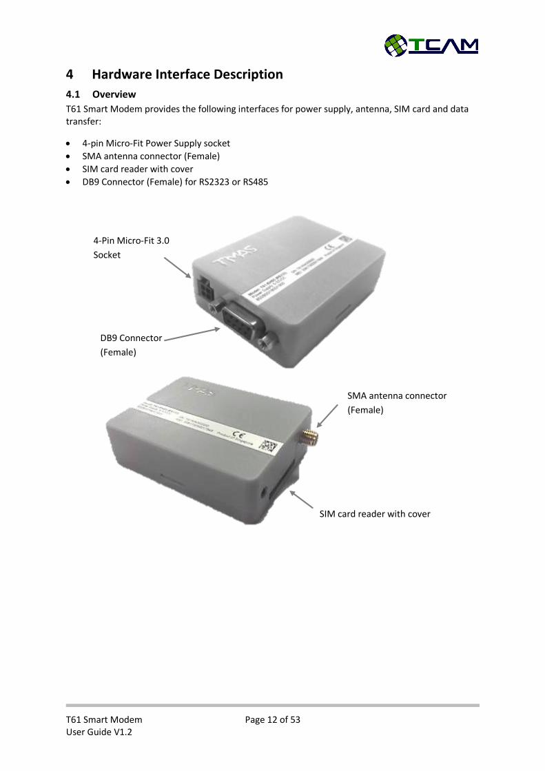
T61 Smart Modem provides the following interfaces for power supply, antenna, SIM card and data transfer:
4-pin Micro-Fit Power Supply socket
SMA antenna connector (Female)
SIM card reader with cover
DB9 Connector (Female) for RS2323 or RS485
4-Pin Micro-Fit 3.0
Socket
DB9 Connector
(Female)
SMA antenna connector
(Female)
SIM card reader with cover
T61 Smart Modem Page 13 of 53 User Guide V1.2
4.2 Interface Variant
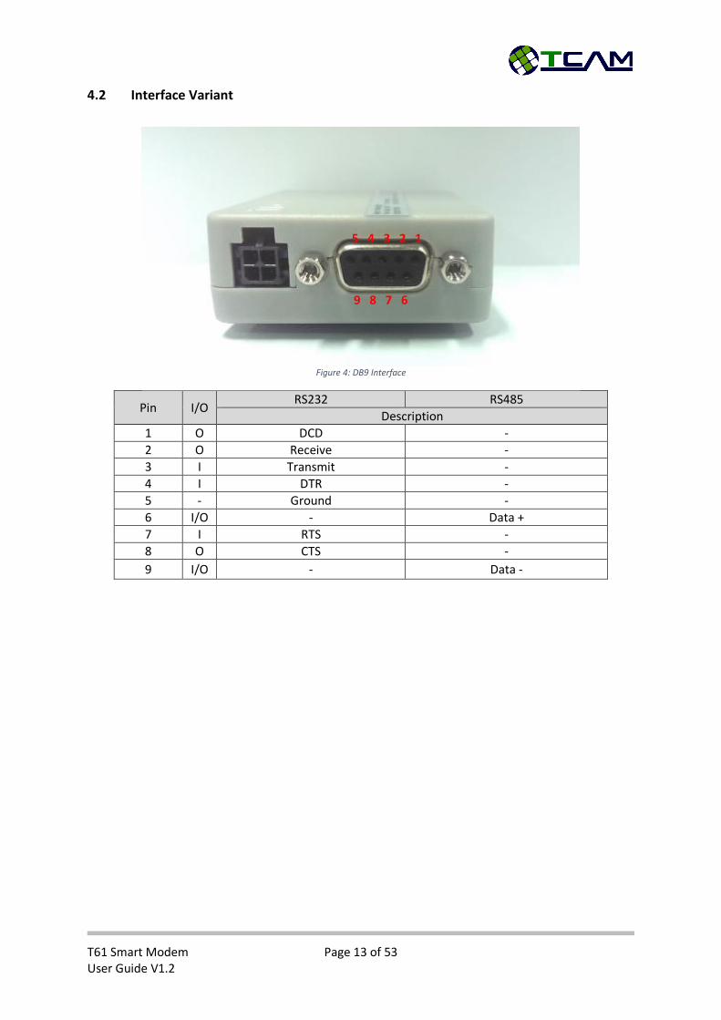
Pin I/O RS232 RS485
Description
1 O DCD -
2 O Receive -
3 I Transmit -
4 I DTR -
5 - Ground -
6 I/O - Data +
7 I RTS -
8 O CTS -
9 I/O - Data -
5 4 3 2 1
9 8 7 6
Figure 4: DB9 Interface

T61 Smart Modem Page 14 of 53 User Guide V1.2
4.3 4-Pin Micro-Fit Interface
T61 Smart Modem is powered by a DC with range of 5-32VDC, via 4-pin micro-Fit connector (shown in Figure 5). The other two pins are one digital/anolog input and one digital output. Detailed pin assignment please refer to Table below.
Pin Description
1 VCC: 5-32 VDC
2 Ground
3 Digital Input/Analog Input
4 Digital Output
4.4 SIM Interface
The SIM – with the circuit side facing upwards – is inserted by gently pushing into the SIM card until it snaps hold. After that, close the SIM cover for protection. The process is demonstrated above.
The SIM card cover is designed for tight locking. To open it, please open from the left side of the
cover.
To extract out the SIM card, push the SIM card inward to unlock the SIM card.
Figure 5: 4-Pin Micro Fit Interface
1 2
3 4
3 4
SIM extracted SIM inserted SIM covered
T61 Smart Modem Page 15 of 53 User Guide V1.2
4.5 Status LED
T61 Smart Modem has one red LED indicating the device and network status. When the device
detects no SIM card inserted or no antenna or not yet connected to network, the LED will blink fast
at approximately every one second. The detail “ON/OFF” timing of the LED is presented in the
following table.
LED mode Operating status of T61
Permanently off T61 is not powered on or T61 is in Hyper-terminal Configuration
50ms ON/990ms OFF Data Call in progress
50ms ON/1990ms OFF During data transfer
50ms ON/3990ms OFF Registered to a network. No call, no data transfer
500ms ON/500ms OFF Limited Network Services (e.g. because no SIM/USIM, no PIN or during network search)
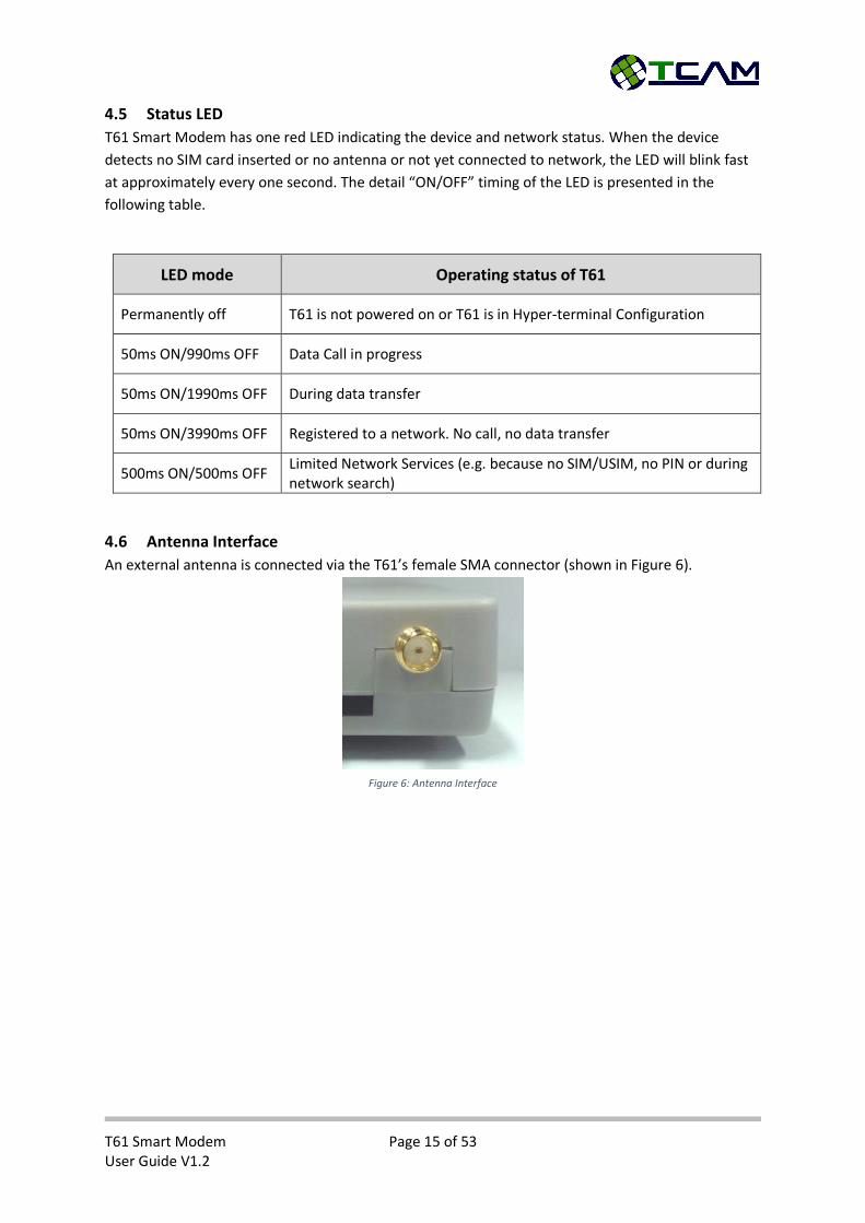
4.6 Antenna Interface
An external antenna is connected via the T61’s female SMA connector (shown in Figure 6).
Figure 6: Antenna Interface
T61 Smart Modem Page 16 of 53 User Guide V1.2
5 Mechanics, Mounting and Packaging
5.1 Mechanical Dimensions

T61 Smart Modem Page 17 of 53 User Guide V1.2
5.2 Mounting T61 Smart Modem
T61 is equipped with a mounting clip as shown in Figure 7.
To mount the device, first please fix the mounting clip on the wall or a DIN rail and then attach the
T61 device to the clip.
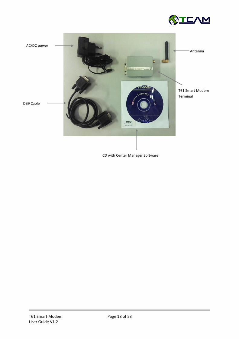
5.3 Packaging
T61 Smart Modem is available as a standalone terminal. It can be ordered without any accessories.
T61 Smart Modem Kit Set is also available.
T61 Smart Modem Kit Set includes all necessary accessories:
T61 Smart Modem Terminal
AC/DC power adapter with 4-pins Micro-Fit plug, DC 12V, 0.5A
Female-to-male DB9 modem cable
Quad-band Antenna (2dBi)
CD with TMAS Center Manager Software
Mounting Clip
M3 Mounting Holes
Figure 7: T61 with mounting clip
T61 Smart Modem Page 18 of 53 User Guide V1.2
AC/DC power
adapter Antenna
T61 Smart Modem
Terminal
DB9 Cable
CD with Center Manager Software
T61 Smart Modem Page 19 of 53 User Guide V1.2
6 Get Started T61 Smart Modem is a plug-and-play device. After simple configuration it will be ready to carry out
its mission. This section will guide you step-by-step to setup your device. For a more intuitive setup
guide, you can also watch our video guide online (https://www.youtube.com/watch?v=0YXLVhjDXEA).
The video guide is also included in the Center Manager Installation CD.
6.1 Box Open
T61 Smart Modem Kit Set will be delivered with all necessary accessories inside.
Before starting the setup, please make sure your SIM card and power socket is ready. Unpack everything from the box and follow the steps below:
Step 1: Open the SIM card cover from left using a sharp pointer.
Step 2: Insert your SIM card into the tray with circuit side facing upwards. Close the SIM cover.
Step 3: Screw the antenna to the SMA connector. Please be gentle, over screwing may cause damage to the device.
Step 4: Off your socket power and plug in the adapter. Connect the square head to the device’s power socket.
Now your device is ready to power up.
T61 Smart Modem Page 20 of 53 User Guide V1.2
7 Device Configuration T61 Smart Modem is robust and comprehensive. Most of its properties are configurable to cater
different requirements. In this chapter, all configuration options will be discussed.
There are two ways to configure T61 Smart Modem. One way is using TMAS Center Manager
software (Refer to the Center Manager User Guide). The other way is to use serial terminal software.
And terminal software will do the job, while HyperTerminal and Hercules are recommended. A
configuration menu is embedded inside T61 smart gateway. User can easily configure the device via
serial port. In this chapter, we will focus on the serial port configuration method. All screenshots are
taken using HyperTerminal.
7.1 Initial Setup
To configure T61 smart gateway, serial terminal software should be configured as followed:
Baud Rate: 115200bps
Data Bits: 8
Parity Bit: None
Flow Control: None
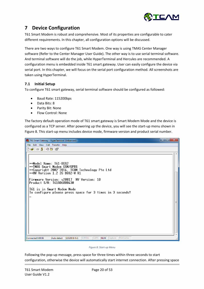
The factory default operation mode of T61 smart gateway is Smart Modem Mode and the device is
configured as a TCP server. After powering up the device, you will see the start-up menu shown in
Figure 8. This start-up menu includes device mode, firmware version and product serial number.
Figure 8: Start-up Menu
Following the pop-up message, press space for three times within three seconds to start
configuration, otherwise the device will automatically start internet connection. After pressing space
T61 Smart Modem Page 21 of 53 User Guide V1.2
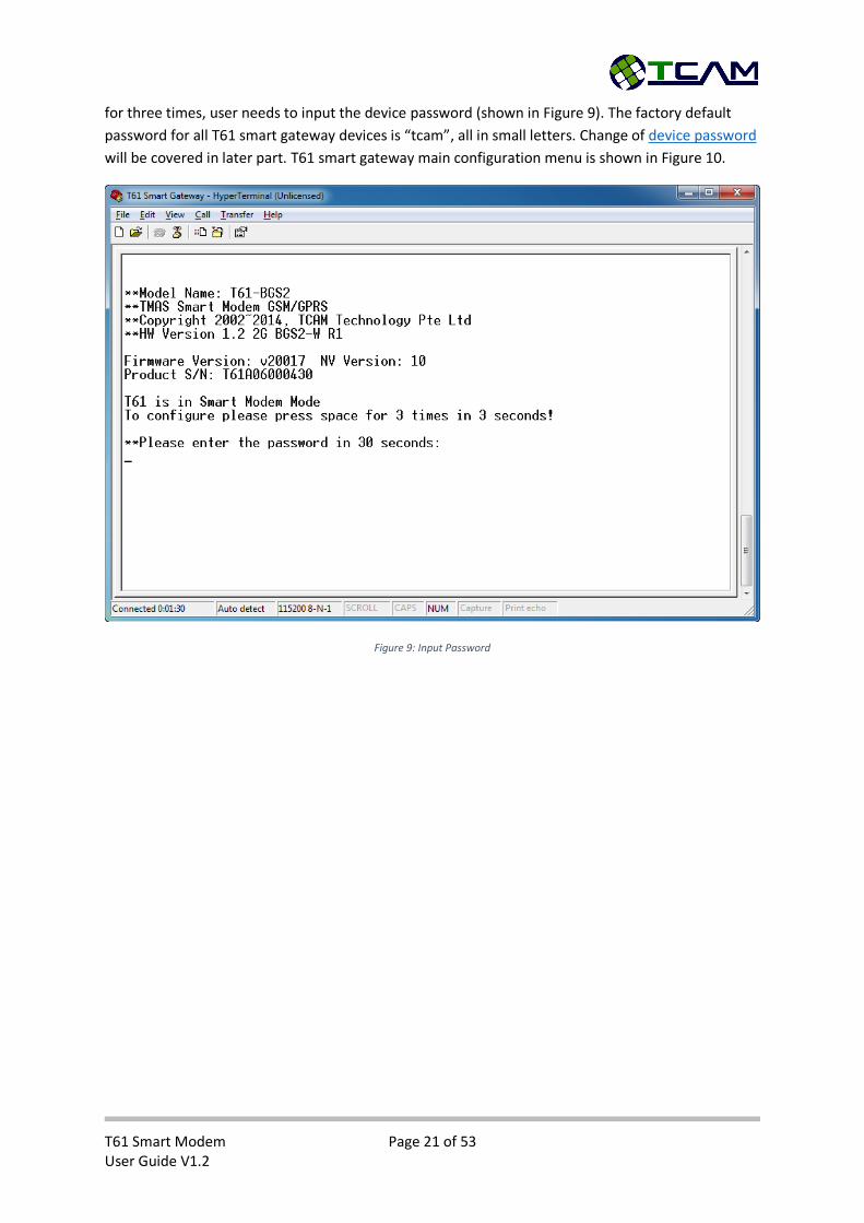
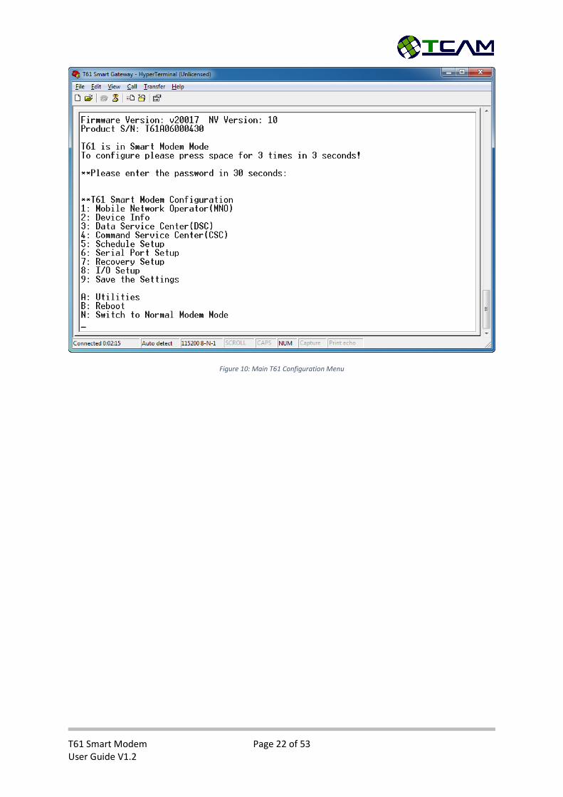
for three times, user needs to input the device password (shown in Figure 9). The factory default
password for all T61 smart gateway devices is “tcam”, all in small letters. Change of device password
will be covered in later part. T61 smart gateway main configuration menu is shown in Figure 10.
Figure 9: Input Password
T61 Smart Modem Page 22 of 53 User Guide V1.2
Figure 10: Main T61 Configuration Menu

T61 Smart Modem Page 23 of 53 User Guide V1.2
7.2 Switching Between Smart Modem Mode and Normal Modem Mode
7.2.1 Switch to Normal Modem Mode
If your T61 devices are utilized as normal modem, you need to switch them to Normal Modem
Mode. At the main T61 configuration menu, select option “N: Switch to Normal Modem Mode”
(shown in Figure 11) by pressing “n” or “N”.
Figure 11: Switch to Normal Modem Mode
T61 Smart Modem Page 24 of 53 User Guide V1.2
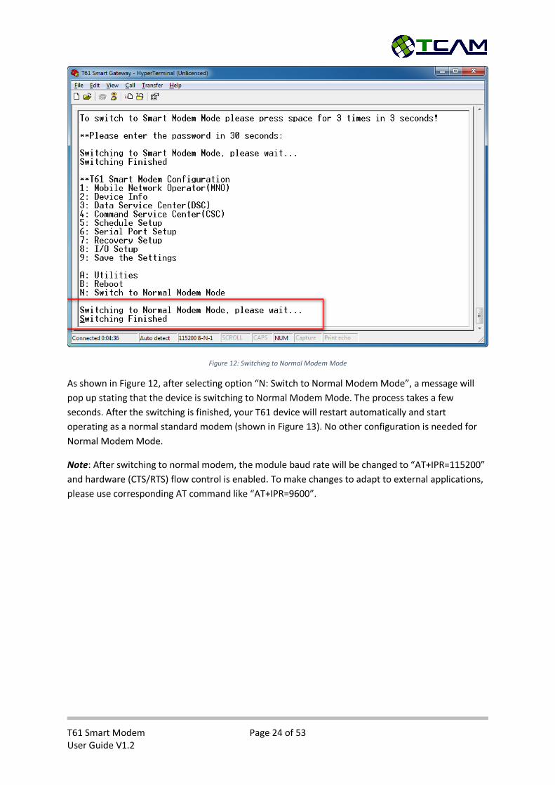
Figure 12: Switching to Normal Modem Mode
As shown in Figure 12, after selecting option “N: Switch to Normal Modem Mode”, a message will
pop up stating that the device is switching to Normal Modem Mode. The process takes a few
seconds. After the switching is finished, your T61 device will restart automatically and start
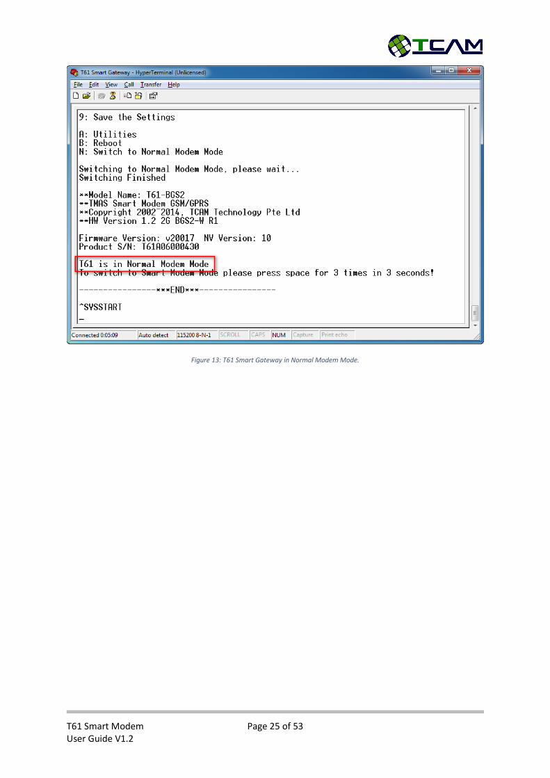
operating as a normal standard modem (shown in Figure 13). No other configuration is needed for
Normal Modem Mode.
Note: After switching to normal modem, the module baud rate will be changed to “AT+IPR=115200”
and hardware (CTS/RTS) flow control is enabled. To make changes to adapt to external applications,
please use corresponding AT command like “AT+IPR=9600”.
T61 Smart Modem Page 25 of 53 User Guide V1.2
Figure 13: T61 Smart Gateway in Normal Modem Mode.
T61 Smart Modem Page 26 of 53 User Guide V1.2
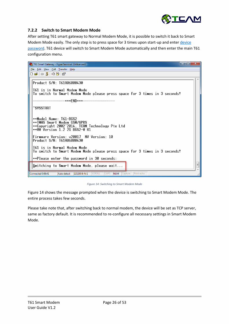
7.2.2 Switch to Smart Modem Mode
After setting T61 smart gateway to Normal Modem Mode, it is possible to switch it back to Smart
Modem Mode easily. The only step is to press space for 3 times upon start-up and enter device
password. T61 device will switch to Smart Modem Mode automatically and then enter the main T61
configuration menu.
Figure 14: Switching to Smart Modem Mode
Figure 14 shows the message prompted when the device is switching to Smart Modem Mode. The
entire process takes few seconds.
Please take note that, after switching back to normal modem, the device will be set as TCP server,
same as factory default. It is recommended to re-configure all necessary settings in Smart Modem
Mode.
T61 Smart Modem Page 27 of 53 User Guide V1.2
7.3 Smart Modem Configuration
T61 smart gateway is flexible. Most of its parameters are configurable to suit various requirements.
The configuration procedure is simple and intuitive. Devices only need to configure once upon the
first usage. Afterwards, the device will memorize all settings in its non-volatile memory.
The following section will start with generation guidelines for configuration using serial terminal
software, such as general keys, saving procedure, reboot options and etc. Then it will focus on the
major settings including network operator settings, serial interface settings, data center and
command center settings and etc.
7.3.1 General Guidelines for Smart Modem Configuration
The following is some general guidelines applicable to most of the menu settings.
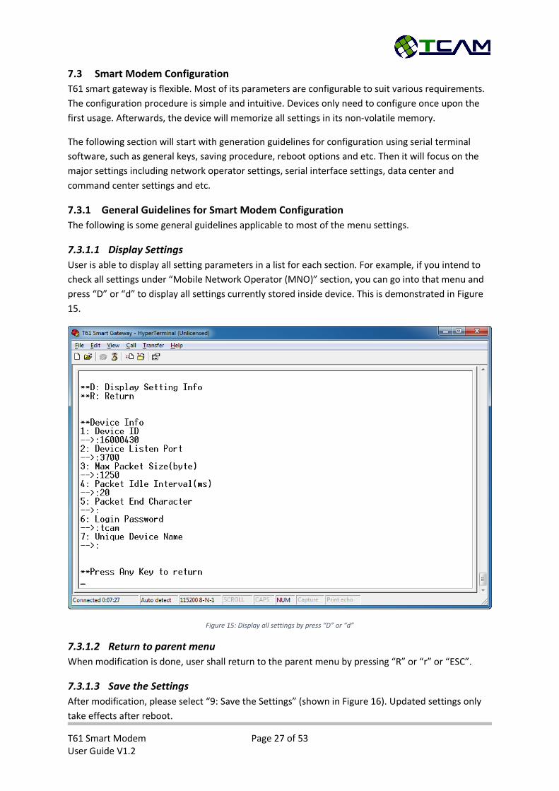
7.3.1.1 Display Settings
User is able to display all setting parameters in a list for each section. For example, if you intend to
check all settings under “Mobile Network Operator (MNO)” section, you can go into that menu and
press “D” or “d” to display all settings currently stored inside device. This is demonstrated in Figure
15.
Figure 15: Display all settings by press “D” or “d”
7.3.1.2 Return to parent menu
When modification is done, user shall return to the parent menu by pressing “R” or “r” or “ESC”.
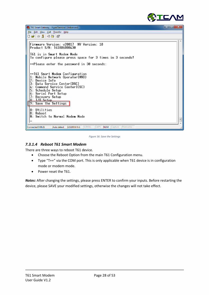
7.3.1.3 Save the Settings
After modification, please select “9: Save the Settings” (shown in Figure 16). Updated settings only
take effects after reboot.
T61 Smart Modem Page 28 of 53 User Guide V1.2
Figure 16: Save the Settings
7.3.1.4 Reboot T61 Smart Modem
There are three ways to reboot T61 device.
Choose the Reboot Option from the main T61 Configuration menu.
Type “T++” via the COM port. This is only applicable when T61 device is in configuration
mode or modem mode.
Power reset the T61.
Notes: After changing the settings, please press ENTER to confirm your inputs. Before restarting the
device, please SAVE your modified settings, otherwise the changes will not take effect.
T61 Smart Modem Page 29 of 53 User Guide V1.2
7.3.2 Mobile Network Operator (MNO)
This section is more related to the SIM card network operator. Some settings can be very crucial for
T61 Smart Modem to function properly, like Access Point Name (APN).
7.3.2.1 GPRS Dial-Up Number
This parameter is not utilized by T61 device. It is a reference for user when the device is used as
standard dial-up modem.
String *99***1# (Default) This is the default dial-up number for standard modem
7.3.2.2 PPP User Name & PPP Password
These two parameters are optional and may be required by certain SIM card for internet connection.
The factory default values for these two parameters are blank.
7.3.2.3 Access Point Name (APN)
This parameter is crucial to most of network operators. SIM cards need this parameter to be in place
in order to access the internet.
String Internet This parameter is mandatory for internet access
7.3.2.4 SIM PIN
If the SIM card is PIN protected, the module will not able to access the SIM card functions without a
correct PIN number. Please contact the mobile network operator to check whether your SIM card is
PIN protected.
String Default setting is blank
T61 Smart Modem Page 30 of 53 User Guide V1.2
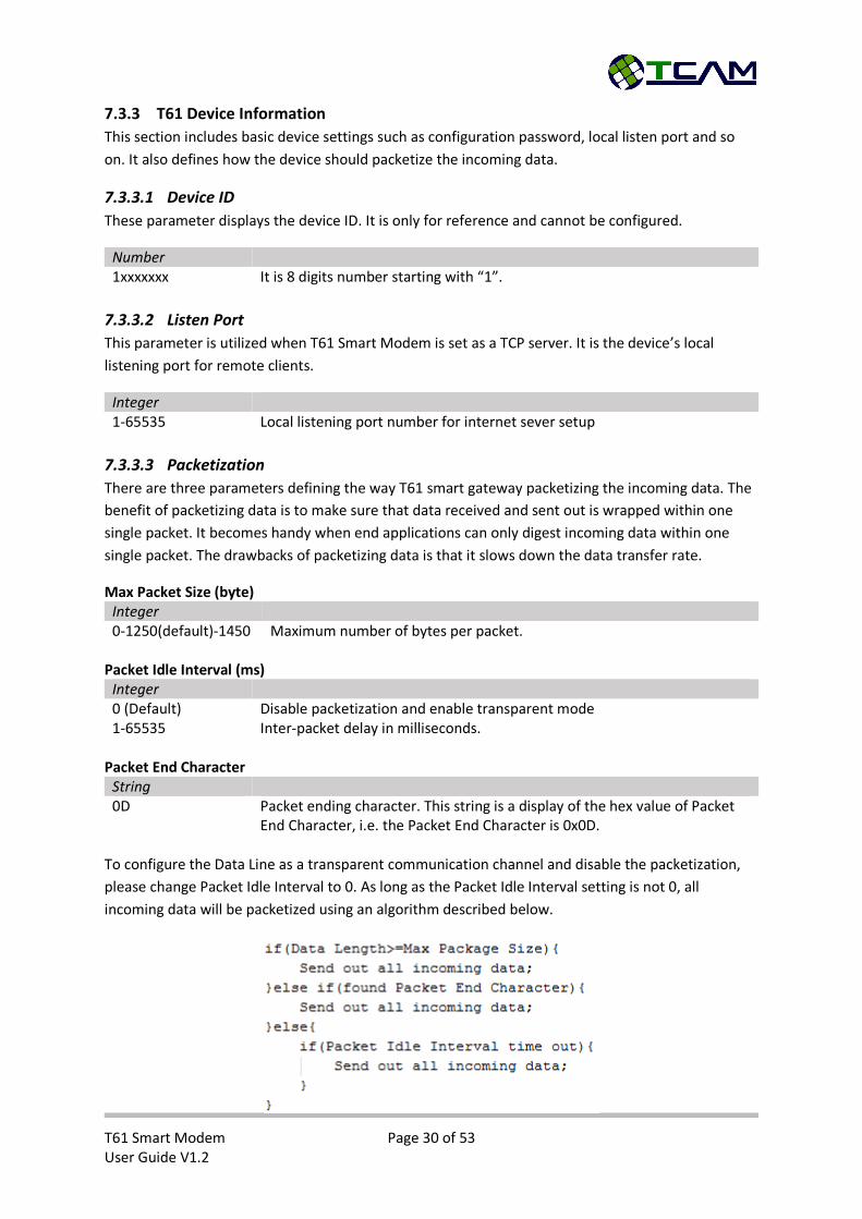
7.3.3 T61 Device Information
This section includes basic device settings such as configuration password, local listen port and so
on. It also defines how the device should packetize the incoming data.
7.3.3.1 Device ID
These parameter displays the device ID. It is only for reference and cannot be configured.
Number 1xxxxxxx It is 8 digits number starting with “1”.
7.3.3.2 Listen Port
This parameter is utilized when T61 Smart Modem is set as a TCP server. It is the device’s local
listening port for remote clients.
Integer 1-65535 Local listening port number for internet sever setup
7.3.3.3 Packetization
There are three parameters defining the way T61 smart gateway packetizing the incoming data. The
benefit of packetizing data is to make sure that data received and sent out is wrapped within one
single packet. It becomes handy when end applications can only digest incoming data within one
single packet. The drawbacks of packetizing data is that it slows down the data transfer rate.
Max Packet Size (byte) Integer 0-1250(default)-1450 Maximum number of bytes per packet.
Packet Idle Interval (ms)
Integer 0 (Default) Disable packetization and enable transparent mode 1-65535 Inter-packet delay in milliseconds.
Packet End Character
String 0D Packet ending character. This string is a display of the hex value of Packet
End Character, i.e. the Packet End Character is 0x0D. To configure the Data Line as a transparent communication channel and disable the packetization,
please change Packet Idle Interval to 0. As long as the Packet Idle Interval setting is not 0, all
incoming data will be packetized using an algorithm described below.

T61 Smart Modem Page 31 of 53 User Guide V1.2
7.3.3.4 Login Password
This parameter defines the password required to enter T61 Configuration menus. The factory default
password is “tcam”, all in small letters. User can change this password upon first login or leave as
default.
String tcam This is the default password, user can change to another one with
maximum length of 8 bytes
7.3.3.5 Unique Device Name
This parameter is the same as the device name recorded in Center Manager if it is in use. It can be
configured to user defined device name or different serial number assigned by customers for
applications. This device name will be used for SMS alert.
String Device Name A name string up to 18 characters.
T61 Smart Modem Page 32 of 53 User Guide V1.2
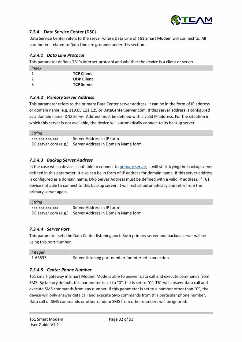
7.3.4 Data Service Center (DSC)
Data Service Center refers to the server where Data Line of T61 Smart Modem will connect to. All
parameters related to Data Line are grouped under this section.
7.3.4.1 Data Line Protocol
This parameter defines T61’s internet protocol and whether the device is a client or server.
Index 1 TCP Client 2 UDP Client 3 TCP Server
7.3.4.2 Primary Server Address
This parameter refers to the primary Data Center server address. It can be in the form of IP address
or domain name, e.g. 119.65.111.125 or DataCenter.server.com. If this server address is configured
as a domain name, DNS Server Address must be defined with a valid IP address. For the situation in
which this server is not available, the device will automatically connect to its backup server.
String xxx.xxx.xxx.xxx Server Address in IP form DC.server.com (e.g.) Server Address in Domain Name form
7.3.4.3 Backup Server Address
In the case which device is not able to connect to primary server, it will start trying the backup server
defined in this parameter. It also can be in form of IP address for domain name. If this server address
is configured as a domain name, DNS Server Address must be defined with a valid IP address. If T61
device not able to connect to this backup server, it will restart automatically and retry from the
primary server again.
String xxx.xxx.xxx.xxx Server Address in IP form DC.server.com (e.g.) Server Address in Domain Name form
7.3.4.4 Server Port
This parameter sets the Data Center listening port. Both primary server and backup server will be
using this port number.
Integer 1-65535 Server listening port number for internet connection
7.3.4.5 Center Phone Number
T61 smart gateway in Smart Modem Mode is able to answer data call and execute commands from
SMS. By factory default, this parameter is set to “0”. If it is set to “0”, T61 will answer data call and
execute SMS commands from any number. If this parameter is set to a number other than “0”, the
device will only answer data call and execute SMS commands from this particular phone number.
Data call or SMS commands or other random SMS from other numbers will be ignored.
T61 Smart Modem Page 33 of 53 User Guide V1.2
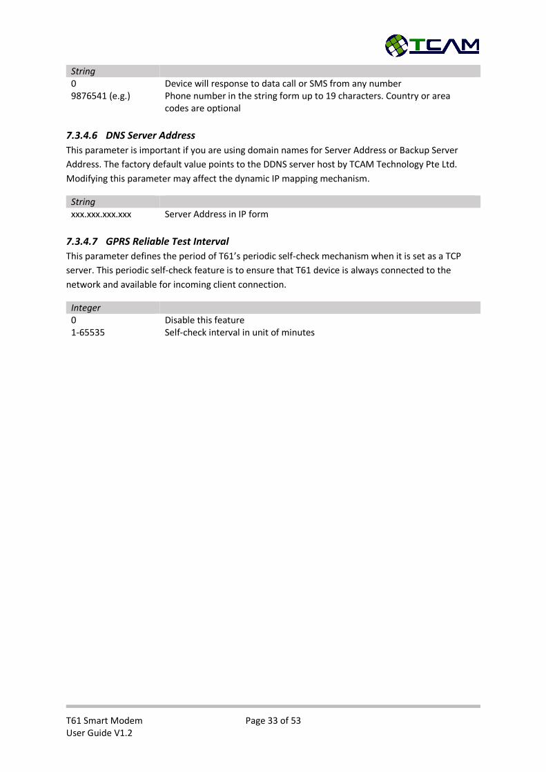
String 0 Device will response to data call or SMS from any number 9876541 (e.g.) Phone number in the string form up to 19 characters. Country or area
codes are optional
7.3.4.6 DNS Server Address
This parameter is important if you are using domain names for Server Address or Backup Server
Address. The factory default value points to the DDNS server host by TCAM Technology Pte Ltd.
Modifying this parameter may affect the dynamic IP mapping mechanism.
String xxx.xxx.xxx.xxx Server Address in IP form
7.3.4.7 GPRS Reliable Test Interval
This parameter defines the period of T61’s periodic self-check mechanism when it is set as a TCP
server. This periodic self-check feature is to ensure that T61 device is always connected to the
network and available for incoming client connection.
Integer 0 Disable this feature 1-65535 Self-check interval in unit of minutes

T61 Smart Modem Page 34 of 53 User Guide V1.2
7.3.5 Command Service Center (CSC)
Command Service Center is where Command Line connects to. It can be enabled or disable by
configuring the Server IP Address.
7.3.5.1 Server IP Address
This parameter defines the IP address of the Command Service Center. If it is set to empty,
Command Line Connection will be disabled.
String xxx.xxx.xxx.xxx Server Address in IP form DC.server.com (e.g.) Server Address in Domain Name form Change it to empty to disable Command Line Connection
7.3.5.2 Server Port Number
This parameter defines the port number of the Command Service Center. It cannot be set to empty
or 0 otherwise device will encounter a problem during connection setup.
Integer 1-65535 Server listening port number for internet connection. This is mandatory.
7.3.5.3 Heartbeat Interval
This parameter refers to the time interval in seconds for device to send a heartbeat via Command
Line to the Command Service Center. The heartbeat will report the device current status including
signal strength, IP address and whether the data line is still online. Every heartbeat is 11 bytes long.
The Command Service Center will judge whether the remote device is still functioning by observing
its heartbeat. This parameter is not applicable if Command Service Center option is configured as
disabled.
Integer 0 Disable this feature (Not recommended) 10-65535 Heartbeat interval in the unit of a second

T61 Smart Modem Page 35 of 53 User Guide V1.2
7.3.6 Schedule to Connect Settings
These settings are only applicable if the Activation Method of T61 Smart Modem is set to schedule
to connect.
7.3.6.1 Module ON/OFF when IDLE
There are two idle modes of the T61 Smart Modem when utilizes Schedule to Connect. T61 will enter
idle mode after 1 minute lack of activity. User can configure whether the device should shut down
the module or not during idle mode. If this parameter is set to 0, module will be powered down
before T61 device entering idle mode. Otherwise, T61 device only closes the connection but leaves
the module on. If the module remains on, T61 device is able to respond to incoming data call or SMS
control commands. If the module is shut down, the device is not reachable until it wakes up from
idle mode.
Index 0 Module OFF when IDLE 1 Module ON when IDLE
7.3.6.2 Device Time Zone & Connection Time
These two parameters are currently not applicable.
7.3.6.3 Connection Interval (Minutes)
This parameter defines the interval time between two successive connections. If T61 device is
configured to connect on schedule, it will only wake up upon multiple of the interval timing. For
instance, if connection interval is set to 5 minutes, it will start its connection at the 0th minute. If
there is no activity (no data from serial and module interfaces) for more than 1 minute, the device
will enter idle mode and wake up at the 5th minute. If the data service center is not available, it will
keep trying until successfully connect to data service center. T61 device will not enter idle mode
when it is connecting to data center or communicating with data center, even when it is at multiple
of the interval timing.
Integer 5-65535 Connection interval in minutes

T61 Smart Modem Page 36 of 53 User Guide V1.2
7.3.7 Serial Port Setup
Serial interface settings are also very important for external applications. T61 smart gateway in
Smart Modem Mode can accept a wild range of baud rates.
7.3.7.1 Baud Rate
T61-EHS5 and T61-BGS2 have different ranges of baud rates. Currently autobauding is not supported
by T61-EHS5 or T61-BGS2.
Index 0 300 1 1200 2 2400 3 4800 4 9600 5 19200 6 38400 7 57600 8 115200 9 230400 A (T61-EHS5 only) 460800
7.3.7.2 Data Bits
T61 smart gateway in Smart Modem Mode is able to accept 7 data bits with odd/even/mark/none
parity bit. It also support 8 data bits without any parity bit. For the current firmware version, if the
device is set to 8 data bits, the parity bit must be set to none.
Index 7 7 Data bits 8 8 Data bits
7.3.7.3 Parity Bit
Four parity bit options are available:
Index 0 None parity bit 1 Odd 2 Even 3 Mark
7.3.7.4 Stop Bit
T61 smart gateway in Smart Modem Mode supports 1 or 2 stop bits.
Index 1 1 stop bit 2 2 stop bits
T61 Smart Modem Page 37 of 53 User Guide V1.2
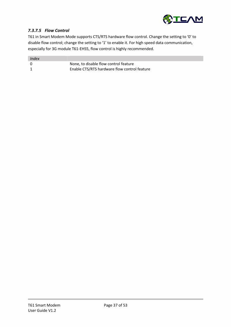
7.3.7.5 Flow Control
T61 in Smart Modem Mode supports CTS/RTS hardware flow control. Change the setting to ‘0’ to
disable flow control; change the setting to ‘1’ to enable it. For high speed data communication,
especially for 3G module T61-EHS5, flow control is highly recommended.
Index 0 None, to disable flow control feature 1 Enable CTS/RTS hardware flow control feature

T61 Smart Modem Page 38 of 53 User Guide V1.2
7.3.8 Recovery Setup
This section includes parameters related to recovery and redundancy mechanisms. User is able to
define when to activate the data line connection, how to recover from data line connection lost and
how frequent the device resets itself to avoid malfunctioning.
7.3.8.1 Activation Option
This parameter defines the condition for T61 Smart Modem to start its data line connection. If this
parameter is not 0, the device will become idle after powering up and wait for the activation
condition to be satisfied.
Index 0 Automatic – Start connection automatically upon power-up 1 Wait for SMS – Start connection after receiving a SMS from the Center
Phone Number. 2 Wait for Call – Start connection after receiving a Call from the Center
Phone Number. 3 Wait for Control SMS – Start connection after receiving a predefined SMS. 4 Connect on Schedule – Start connection periodically with a defined
interval. The only way to activate “Schedule to Connect” feature is to configure this “Activation Option” to be “Connect on Schedule”.
7.3.8.2 Recovery Option
This parameter defines how T61 device should restart the connection when there is connection lost.
Index 0 Constant Retry – T61 device will keep retrying to connect to Data Service
Center without any waiting time. 1 Gradually Retry – T61 device keep retrying to connect to Data Service
Center after a waiting interval. This waiting interval will increase exponentially according to the number times device resets.
2 Wait for SMS – Upon connection lost, T61 device will retry its connection to data center for three times. If the connection is still failed, it will become idle and be waiting for a SMS from the Center Phone Number to restart its connection.
3 Wait for Call – Upon connection lost, T61 device will retry its connection to data center for three times. If the connection is still failed, it will become idle and be waiting for a Call from the Center Phone Number to restart its connection.
7.3.8.3 IP Address Report
If this feature is enabled and the device will update its latest IP when it is available via either SMS or
DDNS update.
Boolean 0 Disable IP report function 1 Enable SMS report function. When device obtains a new IP it will send a
SMS to the Center Phone Number if it is not “0”. 2 Enable IP DDNS update. When device obtains a new IP it will update its IP
to a DDNS server to update its domain name, T61AXXXXXXXX.tmas.com
T61 Smart Modem Page 39 of 53 User Guide V1.2
using http protocol. Please contact TCAM Technology if you want this feature to be enabled.
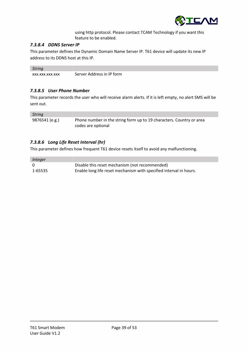
7.3.8.4 DDNS Server IP
This parameter defines the Dynamic Domain Name Server IP. T61 device will update its new IP
address to its DDNS host at this IP.
String xxx.xxx.xxx.xxx Server Address in IP form
7.3.8.5 User Phone Number
This parameter records the user who will receive alarm alerts. If it is left empty, no alert SMS will be
sent out.
String 9876541 (e.g.) Phone number in the string form up to 19 characters. Country or area
codes are optional
7.3.8.6 Long Life Reset Interval (hr)
This parameter defines how frequent T61 device resets itself to avoid any malfunctioning.
Integer 0 Disable this reset mechanism (not recommended) 1-65535 Enable long life reset mechanism with specified interval in hours.
T61 Smart Modem Page 40 of 53 User Guide V1.2
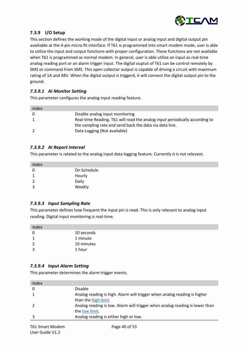
7.3.9 I/O Setup
This section defines the working mode of the digital input or analog input and digital output pin
availiable at the 4-pin micro-fit interface. If T61 is programmed into smart modem mode, user is able
to utilize the input and output functions with proper configuration. These functions are not available
when T61 is programmed as normal modem. In general, user is able utilize an input as real-time
analog reading port or an alarm trigger input. The digital ouptut of T61 can be control remotely by
SMS or command from SMS. This open collector output is capable of driving a circuit with maximum
rating of 1A and 48V. When the digital output is triggerd, it will connect the digital output pin to the
ground.
7.3.9.1 AI Monitor Setting
This parameter configures the analog input reading feature.
Index 0 Disable analog input monitoring 1 Real-time Reading. T61 will read the analog input periodically according to
the sampling rate and send back the data via data line. 2 Data Logging (Not available)
7.3.9.2 AI Report Interval
This parameter is related to the analog input data logging feature. Currently it is not relevant.
Index 0 On Schedule 1 Hourly 2 Daily 3 Weekly
7.3.9.3 Input Sampling Rate
This parameter defines how frequent the input pin is read. This is only relevant to analog input
reading. Digital input monitoring is real-time.
Index 0 10 seconds 1 1 minute 2 10 minutes 3 1 hour
7.3.9.4 Input Alarm Setting
This parameter determines the alarm trigger events.
Index 0 Disable 1 Analog reading is high. Alarm will trigger when analog reading is higher
than the high limit. 2 Analog reading is low. Alarm will trigger when analog reading is lower than
the low limit. 3 Analog reading is either high or low.
T61 Smart Modem Page 41 of 53 User Guide V1.2
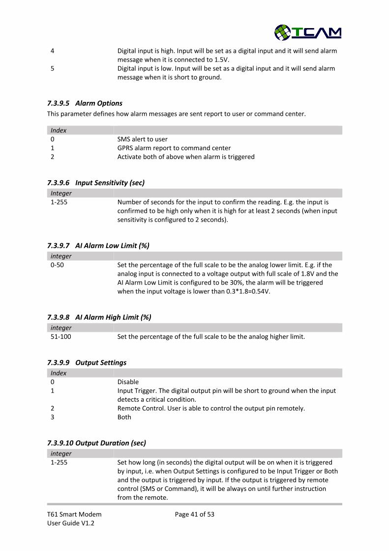
4 Digital input is high. Input will be set as a digital input and it will send alarm message when it is connected to 1.5V.
5 Digital input is low. Input will be set as a digital input and it will send alarm message when it is short to ground.
7.3.9.5 Alarm Options
This parameter defines how alarm messages are sent report to user or command center.
Index 0 SMS alert to user 1 GPRS alarm report to command center 2 Activate both of above when alarm is triggered
7.3.9.6 Input Sensitivity (sec)
Integer 1-255 Number of seconds for the input to confirm the reading. E.g. the input is
confirmed to be high only when it is high for at least 2 seconds (when input sensitivity is configured to 2 seconds).
7.3.9.7 AI Alarm Low Limit (%)
integer 0-50 Set the percentage of the full scale to be the analog lower limit. E.g. if the
analog input is connected to a voltage output with full scale of 1.8V and the AI Alarm Low Limit is configured to be 30%, the alarm will be triggered when the input voltage is lower than 0.3*1.8=0.54V.
7.3.9.8 AI Alarm High Limit (%)
integer 51-100 Set the percentage of the full scale to be the analog higher limit.
7.3.9.9 Output Settings
Index 0 Disable 1 Input Trigger. The digital output pin will be short to ground when the input
detects a critical condition. 2 Remote Control. User is able to control the output pin remotely. 3 Both
7.3.9.10 Output Duration (sec)
integer 1-255 Set how long (in seconds) the digital output will be on when it is triggered
by input, i.e. when Output Settings is configured to be Input Trigger or Both and the output is triggered by input. If the output is triggered by remote control (SMS or Command), it will be always on until further instruction from the remote.

T61 Smart Modem Page 42 of 53 User Guide V1.2
7.3.10 Utilities
T61 Smart Modem provide some basic and handy utility functions for users.
Options 1 Load Default Setting – This is to load the factory default settings back to the
device. 2 Firmware Info – T61 device will display the current firmware version. 3 Setting Restore – This feature is to send a configuration binary file to the
device using Xmodem 1K protocol. It will be useful to restore the device to user defined default settings.
4 Setting Backup – By selecting this function, T61 device will output its current settings as a binary file using Xmodem 1K protocol. User needs to use Xmodem 1K protocol to receive the file. This feature is useful to obtain user defined default settings and to restore devices when needed.
5 Recover Smart Modem Baud Rate – This is a backup recovery option for the situations in which CPU can no longer talk to module. It will set module baud rate to be 230400bps for T61-BGS2 or 460800bps for T61-EHS5.
T61 Smart Modem Page 43 of 53 User Guide V1.2
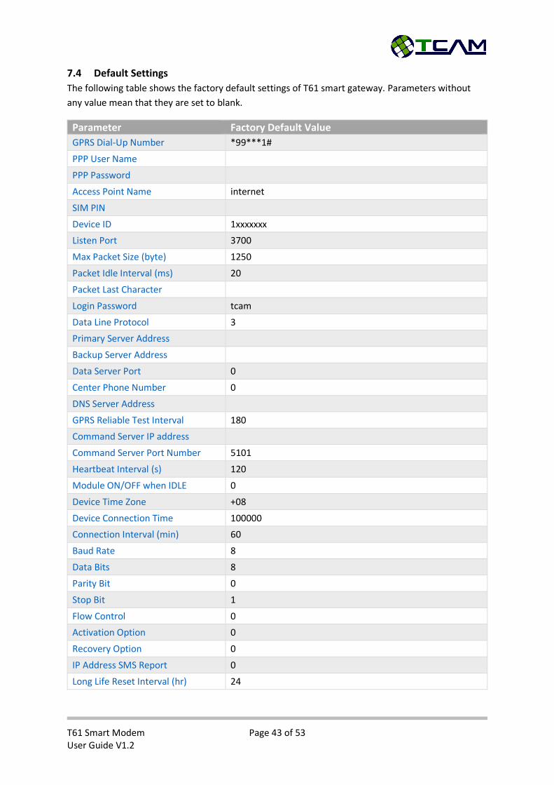
7.4 Default Settings
The following table shows the factory default settings of T61 smart gateway. Parameters without
any value mean that they are set to blank.
Parameter Factory Default Value
GPRS Dial-Up Number *99***1#
PPP User Name
PPP Password
Access Point Name internet
SIM PIN
Device ID 1xxxxxxx
Listen Port 3700
Max Packet Size (byte) 1250
Packet Idle Interval (ms) 20
Packet Last Character
Login Password tcam
Data Line Protocol 3
Primary Server Address
Backup Server Address
Data Server Port 0
Center Phone Number 0
DNS Server Address
GPRS Reliable Test Interval 180
Command Server IP address
Command Server Port Number 5101
Heartbeat Interval (s) 120
Module ON/OFF when IDLE 0
Device Time Zone +08
Device Connection Time 100000
Connection Interval (min) 60
Baud Rate 8
Data Bits 8
Parity Bit 0
Stop Bit 1
Flow Control 0
Activation Option 0
Recovery Option 0
IP Address SMS Report 0
Long Life Reset Interval (hr) 24
T61 Smart Modem Page 44 of 53 User Guide V1.2
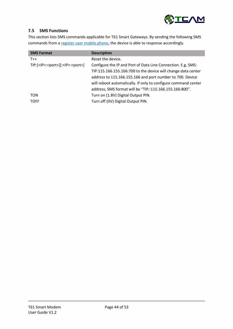
7.5 SMS Functions
This section lists SMS commands applicable for T61 Smart Gateways. By sending the following SMS
commands from a register user mobile phone, the device is able to response accordingly.
SMS Format Description
T++ Reset the device.
TIP:[<IP>:<port>][:<IP>:<port>] Configure the IP and Port of Data Line Connection. E.g. SMS:
TIP:115.166.155.166:700 to the device will change data center
address to 115.166.155.166 and port number to 700. Device
will reboot automatically. If only to configure command center
address, SMS format will be “TIP::115.166.155.166:800”.
TON Turn on (1.8V) Digital Output PIN.
TOFF Turn off (0V) Digital Output PIN.
T61 Smart Modem Page 45 of 53 User Guide V1.2
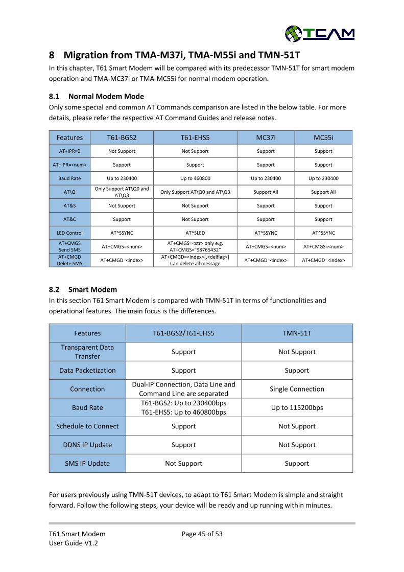
8 Migration from TMA-M37i, TMA-M55i and TMN-51T In this chapter, T61 Smart Modem will be compared with its predecessor TMN-51T for smart modem
operation and TMA-MC37i or TMA-MC55i for normal modem operation.
8.1 Normal Modem Mode
Only some special and common AT Commands comparison are listed in the below table. For more
details, please refer the respective AT Command Guides and release notes.
Features T61-BGS2 T61-EHS5 MC37i MC55i
AT+IPR=0 Not Support Not Support Support Support
AT+IPR=<num> Support Support Support Support
Baud Rate Up to 230400 Up to 460800 Up to 230400 Up to 230400
AT\Q Only Support AT\Q0 and
AT\Q3 Only Support AT\Q0 and AT\Q3 Support All Support All
AT&S Not Support Not Support Support Support
AT&C Support Not Support Support Support
LED Control AT^SSYNC AT^SLED AT^SSYNC AT^SSYNC
AT+CMGS Send SMS
AT+CMGS=<num> AT+CMGS=<str> only e.g. AT+CMGS=”98765432”
AT+CMGS=<num> AT+CMGS=<num>
AT+CMGD Delete SMS
AT+CMGD=<index> AT+CMGD=<index>[,<delflag>]
Can delete all message AT+CMGD=<index> AT+CMGD=<index>
8.2 Smart Modem
In this section T61 Smart Modem is compared with TMN-51T in terms of functionalities and
operational features. The main focus is the differences.
Features T61-BGS2/T61-EHS5 TMN-51T
Transparent Data Transfer
Support Not Support
Data Packetization Support Support
Connection Dual-IP Connection, Data Line and
Command Line are separated Single Connection
Baud Rate T61-BGS2: Up to 230400bps T61-EHS5: Up to 460800bps
Up to 115200bps
Schedule to Connect Support Not Support
DDNS IP Update Support Not Support
SMS IP Update Not Support Support
For users previously using TMN-51T devices, to adapt to T61 Smart Modem is simple and straight
forward. Follow the following steps, your device will be ready and up running within minutes.
T61 Smart Modem Page 46 of 53 User Guide V1.2
Step 1: Request from us the latest Center Manager Software
Step 2: Configure the serial interface to your desired settings.
Step 3: Set Data Service Address & Port Number same as your original data center IP address
and port.
Step 4: Set Command Service Address same as your original data center IP addresses well.
Step 5: Open one additional internet port at your data center and configure that port
number as Command Service Center Port Number.
Step 6: Configure other relevant settings as your original TMN-51T device.
Step 7: Save your settings and reboot.
Now your T61 Smart Modem is ready for operation.
T61 Smart Modem Page 47 of 53 User Guide V1.2
9 Application Notes
9.1 T61 Firmware Update
For the cases that there is a need to patch up the firmware of T61 devices, Center Manager software
provides two convenient ways of doing it. One way is to use direct wire. It is a faster way but devices
need to be connected to Center Manager using RS232 cable. Another way is to update via TCP
connection. This is a slower but it becomes very handy if the devices are deployed at remote. In both
cases, Center Manager software is mandatory. Please refer to the following sections for more
details.
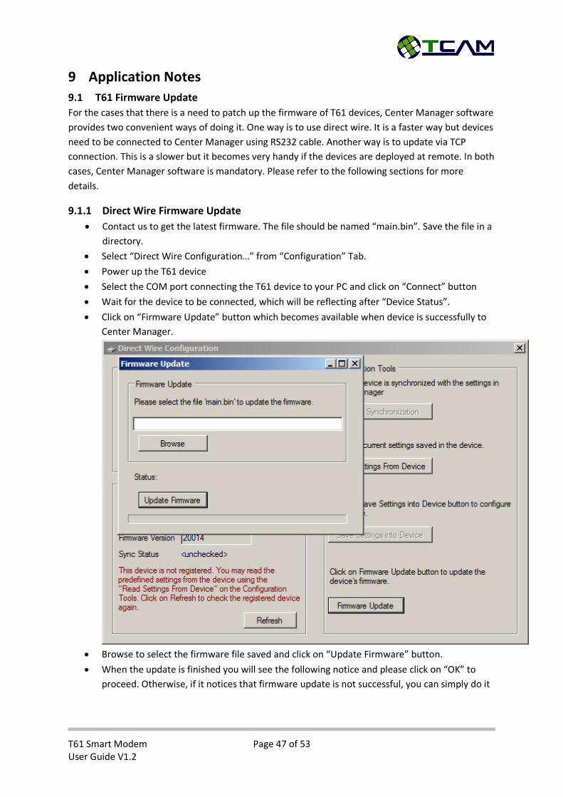
9.1.1 Direct Wire Firmware Update
Contact us to get the latest firmware. The file should be named “main.bin”. Save the file in a
directory.
Select “Direct Wire Configuration…” from “Configuration” Tab.
Power up the T61 device
Select the COM port connecting the T61 device to your PC and click on “Connect” button
Wait for the device to be connected, which will be reflecting after “Device Status”.
Click on “Firmware Update” button which becomes available when device is successfully to
Center Manager.
Browse to select the firmware file saved and click on “Update Firmware” button.
When the update is finished you will see the following notice and please click on “OK” to
proceed. Otherwise, if it notices that firmware update is not successful, you can simply do it
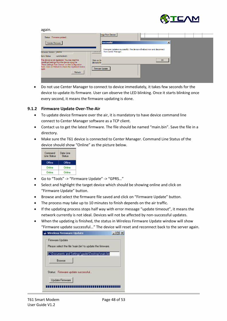
T61 Smart Modem Page 48 of 53 User Guide V1.2
again.
Do not use Center Manager to connect to device immediately, it takes few seconds for the
device to update its firmware. User can observe the LED blinking. Once it starts blinking once
every second, it means the firmware updating is done.
9.1.2 Firmware Update Over-The-Air
To update device firmware over the air, it is mandatory to have device command line
connect to Center Manager software as a TCP client.
Contact us to get the latest firmware. The file should be named “main.bin”. Save the file in a
directory.
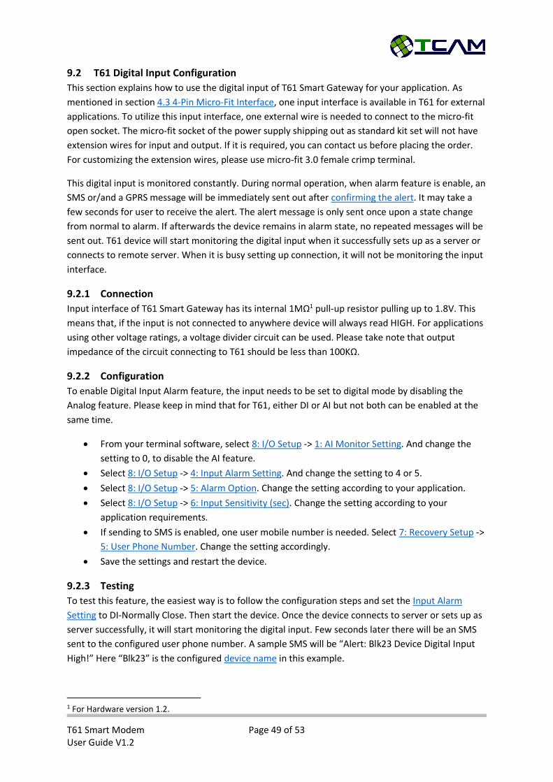
Make sure the T61 device is connected to Center Manager. Command Line Status of the
device should show “Online” as the picture below.
Go to “Tools” -> “Firmware Update” -> “GPRS…”
Select and highlight the target device which should be showing online and click on
“Firmware Update” button.
Browse and select the firmware file saved and click on “Firmware Update” button.
The process may take up to 10 minutes to finish depends on the air traffic.
If the updating process stops half way with error message “update timeout”, it means the
network currently is not ideal. Devices will not be affected by non-successful updates.
When the updating is finished, the status in Wireless Firmware Update window will show
“Firmware update successful…” The device will reset and reconnect back to the server again.
T61 Smart Modem Page 49 of 53 User Guide V1.2
9.2 T61 Digital Input Configuration
This section explains how to use the digital input of T61 Smart Gateway for your application. As
mentioned in section 4.3 4-Pin Micro-Fit Interface, one input interface is available in T61 for external
applications. To utilize this input interface, one external wire is needed to connect to the micro-fit
open socket. The micro-fit socket of the power supply shipping out as standard kit set will not have
extension wires for input and output. If it is required, you can contact us before placing the order.
For customizing the extension wires, please use micro-fit 3.0 female crimp terminal.
This digital input is monitored constantly. During normal operation, when alarm feature is enable, an
SMS or/and a GPRS message will be immediately sent out after confirming the alert. It may take a
few seconds for user to receive the alert. The alert message is only sent once upon a state change
from normal to alarm. If afterwards the device remains in alarm state, no repeated messages will be
sent out. T61 device will start monitoring the digital input when it successfully sets up as a server or
connects to remote server. When it is busy setting up connection, it will not be monitoring the input
interface.
9.2.1 Connection
Input interface of T61 Smart Gateway has its internal 1MΩ1 pull-up resistor pulling up to 1.8V. This
means that, if the input is not connected to anywhere device will always read HIGH. For applications
using other voltage ratings, a voltage divider circuit can be used. Please take note that output
impedance of the circuit connecting to T61 should be less than 100KΩ.
9.2.2 Configuration
To enable Digital Input Alarm feature, the input needs to be set to digital mode by disabling the
Analog feature. Please keep in mind that for T61, either DI or AI but not both can be enabled at the
same time.
From your terminal software, select 8: I/O Setup -> 1: AI Monitor Setting. And change the
setting to 0, to disable the AI feature.
Select 8: I/O Setup -> 4: Input Alarm Setting. And change the setting to 4 or 5.
Select 8: I/O Setup -> 5: Alarm Option. Change the setting according to your application.
Select 8: I/O Setup -> 6: Input Sensitivity (sec). Change the setting according to your
application requirements.
If sending to SMS is enabled, one user mobile number is needed. Select 7: Recovery Setup ->
5: User Phone Number. Change the setting accordingly.
Save the settings and restart the device.
9.2.3 Testing
To test this feature, the easiest way is to follow the configuration steps and set the Input Alarm
Setting to DI-Normally Close. Then start the device. Once the device connects to server or sets up as
server successfully, it will start monitoring the digital input. Few seconds later there will be an SMS
sent to the configured user phone number. A sample SMS will be “Alert: Blk23 Device Digital Input
High!” Here “Blk23” is the configured device name in this example.
1 For Hardware version 1.2.

T61 Smart Modem Page 50 of 53 User Guide V1.2
9.3 T61 SMS Features
When T61 Smart Gateway is programmed as smart modem, it is able to accept simple SMS control
and configuration. This feature will be in place provided that SIM cards applied in applications are
SMS enabled. Please make sure that do not flood T61 devices with SMSs. When module memory is
full, it will not able to receive any SMS until a reset. Incoming SMS will be stored at the first SMS
memory slot and will be deleted after being read by T61 device. Please take note that SMS feature
will only be functioning when the device is not setting up connection. When device is busy setting up
connections, incoming SMS may interfere with the process. To avoid disturbance from random SMS,
SMS features are disabled during connection setup.
9.3.1 Reset T61
Command:
o “T++”
Requirement:
o Center Phone Number is configured as “0” OR
o Center Phone Number is not empty and incoming phone number matches it OR
o User Phone Number is not empty and incoming phone number matches it.
Effects:
o T61 device will reset itself automatically
Replay:
o “OK”
9.3.2 Turn ON Digital Output
Command:
o “TON”
Requirement:
o Digital output is not disabled AND
Center Phone Number is configured as “0” OR
Center Phone Number is not empty and incoming phone number matches it
OR
User Phone Number is not empty and incoming phone number matches it.
Effects:
o Application PIN connected to digital output will be connected to ground.
Replay:
o “OK”
9.3.3 Turn OFF Digital Output
Command:
o “TOFF”
Requirement:
o Digital output is not disabled AND
Center Phone Number is configured as “0” OR
Center Phone Number is not empty and incoming phone number matches it
OR
User Phone Number is not empty and incoming phone number matches it.
T61 Smart Modem Page 51 of 53 User Guide V1.2
Effects:
o Application PIN connected to digital output will be left open.
o If the digital output is configured as input trigger, the alarm will be disarmed when
receiving “TOFF” SMS.
Replay:
o “OK”
9.3.4 Configure Server IP and Port
In the following, DC stands for Data Center, CC stands for Command Center.
Command:
o “TIP:<DC IP>:<DC Port>:<CC IP>:<CC Port>” (Configure both connection)
o “TIP::<CC IP>:<CC Port>” (Configure Command Line connection)
o “TIP:<DC IP>:<DC Port>” (Configure Data Line connection)
Requirement:
o Center Phone Number is not empty OR “0” AND sender phone number matches
Center Phone Number OR
o User Phone Number is not empty AND sender phone number matches User Phone
Number
Effects:
o Device will save the settings in flash memory and reboot
o If device is in TCP server mode, device will change setting to TCP Client and save in
flash memory before reboot
Replay:
o “OK”
9.4 T61 Schedule to Connect
T61 Smart Gateway can be configured to make connections according to a schedule. This feature is
to reduce data usage in maintaining always on connections and also to reduce connection load on
server side. When this mode is activated, the device will only connect to server at certain timing and
perform data communication. After that, device will fall “asleep” to wait for the next connection
timing. To activate this mode, please change activation setting to schedule to connect. There are few
parameters needed in this operation mode. Please refer to Schedule to Connect Settings for more
details.
9.4.1 Start a Connection
To ensure the connection time is predictable, a reference connection time is required. By default it is
10:00:00. T61 uses this parameter to calculate the next connection timing. For instance, if the
connection interval is configured as 60 (minutes), the device will make connections at 00:00:00,
01:00:00 …, 09:00:00, 10:00:00, 11:00:00 …, 23:00:00. There is no RTC module inside T61 device. It is
necessary for T61 to make the first connection to server to synchronize its internal clock with server.
After that it will follow the schedule defined by the reference connection time and connection
interval. Every time T61 successfully connects to command center, it will perform time
synchronization and time drift will be corrected.
T61 Smart Modem Page 52 of 53 User Guide V1.2
9.4.2 End of a Connection
When data communication is done, remove server is able to send a command to inform T61 that it’s
time to “sleep”. After receiving this command, T61 device will actively disconnect from both data
center server and command center server and wait for the next connection timing. If T61 fails to
receive any command from server side for one minute, i.e. the connection has been idle for one
minute, the device will also actively disconnect from the server and fall “asleep”. Thus, it is necessary
to make sure that data communication interval for applications is not larger than one minute.
9.4.3 “Sleeping” Mode
To save power, it is recommended to shut down the module when T61 device is in “sleeping” mode,
waiting for the next connection timing. However, this also means that the device will not be
accessible by any means. If application requires the device to remain accessible all the time, user can
configure the device so that the module will not be powered off when it is waiting for the next
connection timing. In this case, it can be accessed by SMS or Data Call but not GPRS/3G connection.

For more information, please visit
http://www.tcam.com.sg or https://www.facebook.com/TcamTechnology
TCAM TECHNOLOGY PTE LTD 2 Kaki Bukit Ave 1 #05-04 Singapore 417938
Tel: (65) 67461930; Fax: (65) 67461938; Website: www.tcam.com.sg; Company Reg No: 200103565N; GST Reg No: 20-0103565-N