Dynamic Article LinksC<Journal ofMaterials Chemistry
Cite this: DOI: 10.1039/c1jm13512k
www.rsc.org/materials PAPER
Dow
nloa
ded
by C
entr
o de
Inv
estig
acio
nes
Cie
ntíf
icas
Isl
a de
la C
artu
ja o
n 22
Nov
embe
r 20
11Pu
blis
hed
on 2
1 N
ovem
ber
2011
on
http
://pu
bs.r
sc.o
rg |
doi:1
0.10
39/C
1JM
1351
2KView Online / Journal Homepage
Superhydrophobic supported Ag-NPs@ZnO-nanorods with photoactivity inthe visible range†
Manuel Macias-Montero,a Ana Borras,*a Zineb Saghi,b Pablo Romero-Gomez,a Juan R. Sanchez-Valencia,a
Juan C. Gonzalez,a Angel Barranco,a Paul Midgley,b Jose Cotrinoc and Agustin R. Gonzalez-Elipea
Received 23rd July 2011, Accepted 24th October 2011
DOI: 10.1039/c1jm13512k
In this article we present a new type of 1D nanostructures consisting of supported hollow ZnO
nanorods (NRs) decorated with Ag nanoparticles (NPs). The 3D reconstruction by high-angle annular
dark field scanning transmission electron microscopy (HAADF-STEM) electron tomography reveals
that the Ag NPs are distributed along the hollow interior of the ZnO NRs. Supported and vertically
aligned Ag-NPs@ZnO-NRs grow at low temperature (135 �C) by plasma enhanced chemical vapour
deposition on heterostructured substrates fabricated by sputtered deposition of silver on flat surfaces of
Si wafers, quartz slides or ITO. The growth mechanisms of these structures and their wetting behavior
before and after visible light irradiation are critically discussed. The as prepared surfaces are
superhydrophobic with water contact angles higher than 150�. These surfaces turn into
superhydrophilic with water contact angles lower than 10� after prolonged irradiation under both
visible and UV light. The evolution rate of the wetting angle and its dependence on the light
characteristics are related to the nanostructure and the presence of silver embedded within the ZnO
NRs.
Introduction
ZnO is a wide band-gap semiconductor which deserves the
attention of many investigations because of its outstanding
optical, electronic, acoustic or catalytic properties.1 Particularly
interesting in this field are the works devoted to the fabrication
and the specific properties of ZnO 1D nanostructures.1–9 Thus,
ZnO materials formed by a high number of deposited nanowires
have been demonstrated to present quite interesting properties
for applications such as nanosensors, solar cells and photovol-
taics, photonic devices, photocatalysis and, very recently, as
active components in microfluidics.6–11 On the other hand, the
recent literature on 1D nanostructures of ZnO decorated with
silver nanoparticles shows the high performance of these heter-
ostructures in photocatalysis12,13 and antibacterial applications.14
One of the main roles of the 1D nanostructures in microfluidics
relies on the formation of superhydrophobic surfaces, i.e.
surfaces with water contact angles higher than 150�.15–17 With the
aNanotechnology on Surfaces Laboratory, Materials Science Institute ofSeville (ICMSE), CSIC-University of Seville, C/Americo Vespucio 49,41092 Seville, Spain. E-mail: [email protected] of Materials Science and Metallurgy, University ofCambridge, Pembroke Street, CB2 3QZ, Cambridge, UKcDepartment of Atomic and Nuclear Physics, University of Seville, Avda.Reina Mercedes s/n, 41012 Seville, Spain
† Electronic supplementary information (ESI) available: Further TEM,SEM and STEM characterization; contact angle modelling and 3Dreconstruction of the Ag-NPs@ZnO-NRs. See DOI: 10.1039/c1jm13512k
This journal is ª The Royal Society of Chemistry 2011
development of smart and laboratory-on-a-chip devices, a key
characteristic of the surfaces is their reversible transformation
from superhydrophobic into superhydrophilic (WCA close to
0�). Different approaches have been followed for this purpose as,
for example, the use of electric field,11,18–20 controlled heating
treatments21,22 or by irradiation with UV and recovery under VIS
light.10,23 The latter approach is advantageous when using 1D
supported nanostructures since their manufacturing is usually
compatible with the use of masks for patterning hydrophobic/
hydrophilic surfaces, fast hydrophilic conversion, low energy
cost and compatibility with a large number of substrates. In the
present work we show a new type of ZnO based 1D nano-
structures formed by supported hollow polycrystalline ZnO
nanorods (NRs) decorated in their interior by silver nano-
particles (AgNPs). As will be discussed below, the surface formed
by these Ag-NPs@ZnO-NRs, vertically aligned and high-
density, deposited on any substrate surface, undergoes a super-
hydrophobic to superhydrophilic conversion under irradiation
with visible light. As far as we know this is the first time that
wetting photoactivity in the visible range is reported for ZnO 1D
nanostructures. The application of plasma related techniques for
the synthesis and process of nanomaterials has experienced an
important development during the last few years.24 The sup-
ported Ag-NPs@ZnO-NRs were fabricated by plasma enhanced
chemical vapour deposition (PECVD) at low temperatures. A
similar approach has been recently employed for the growth of
randomly oriented core@shell Ag@TiO2 nanofibers (NFs) by
using metallic silver as the substrate.25–27 Those nanostructures
J. Mater. Chem.

Fig. 1 Supported Ag-NPs@ZnO NRs grown by PECVD on a hetero-
structured Ag/Si(100) substrate. (a–d) Cross-section SEM micrographs
recorded for secondary electrons (a and c) and for backscattered electrons
(b and d); (e) normal view SEM image showing the high density of
supported nanostructures prepared by this method; (f) GA-XRD pattern
of the nanostructures.
Dow
nloa
ded
by C
entr
o de
Inv
estig
acio
nes
Cie
ntíf
icas
Isl
a de
la C
artu
ja o
n 22
Nov
embe
r 20
11Pu
blis
hed
on 2
1 N
ovem
ber
2011
on
http
://pu
bs.r
sc.o
rg |
doi:1
0.10
39/C
1JM
1351
2K
View Online
consisted of a core formed by a single crystalline thread of silver
surrounded by a TiO2 shell. Their formation was accounted for
by a volcano-like mechanism where the main driving force is the
release of the surface tension accumulated in a plasma oxidized
silver substrate by the formation of silver threads. By using
a slightly modified experimental approach in this work we have
been able to deposit on any support vertically aligned Ag-
NPs@ZnO-NRs which present a unique hollow nanostructure.
To characterize this hollow structure and the distribution of
silver within the NRs we have made use of the electron tomog-
raphy (ET) in high-angle annular dark field scanning trans-
mission electron microscopy (HAADF-STEM) mode. ET
consists of reconstruction of 3D objects from a series of 2D
projections acquired at different angles. The technique, originally
developed for biological applications,28 has been recently trans-
ferred to materials science and applied to various nanoscale
structures, such as catalysts and semiconductor devices.29,30
HAADF-STEM imaging mode was chosen here for two reasons:
firstly, the HAADF-STEM signal is insensitive to diffraction
contrast, and therefore provides the projection linearity needed
for a reliable tomographic reconstruction; secondly, by choosing
a large enough collection angle, the intensity in the HAADF-
STEM images is approximately proportional to Z2 (Z being the
atomic number of the scattering atom).31 HAADF-STEM mode
is therefore ideal for imaging structures composed of elements
with a large difference in Z, such as catalyst nanoparticles
embedded in a light support.32 We take advantage here of the
high Z difference between silver (ZAg ¼ 47) and ZnO (ZZn ¼ 30,
ZO ¼ 8) to highlight the 3D distribution of the particles within
the wire.
The unique information supplied by this technique has
provided a deep insight into the structure of the Ag-NPs@ZnO-
NRs which, in turn, has allowed us to figure out their formation
by plasma deposition at low temperatures. The proposed
mechanism has similarities with the volcano-like process claimed
by us to account for the formation of the Ag@TiO2 NFs, but
differs completely from the classical vapour–liquid–solid (VLS)
mechanism generally responsible for the formation of 1D
nanostructures in the presence of metal nanoparticles.2–4,32–35
Although still subjected to some discussion, we have also related
the light-induced wetting behaviour of the surfaces formed by the
aligned Ag-NPs@ZnO-NRs with its internal nanostructure as
determined by HAADS-STEM.
Fig. 2 (a) TEM micrograph and SAED pattern (inset) of a single
Ag@ZnO-NW. (b) HRTEM micrograph of the ZnO nanocrystal
showing the growth direction of the ZnO.
Results and discussion
Ag-NPs@ZnO-NR formation and 3D reconstruction
Fig. 1 shows several FESEMmicrographs of the layer formed by
Ag-NPs@ZnO-NRs grown on a Si(100) wafer previously deco-
rated with silver particles deposited by DC sputtering (see the
Experimental section and Fig. S1 in the ESI†). Fig. 1(a)–(d) show
clearly that this layer consists of a continuous set of separated
and vertically aligned NRs supported on the silicon substrate,
with typical surface densities of �109 NRs cm�2 (Fig. 1e). A
statistical analysis of the images renders a mean diameter of �40
nm and a height of �900 nm for the NRs, i.e., an aspect ratio of
20. Both the diameter and length of the NRs are controlled by the
experimental parameters, particularly the deposition time. The
J. Mater. Chem.
number of NRs is determined by both the distribution of silver
particles on the substrate and the precursor arrival rate to the
surface. A thorough study of the factors controlling the forma-
tion of the Ag-NPs@ZnO-NRs is outside the scope of this
communication and will be the subject of a forthcoming work.
The crystal structure of these 1D heterostructures determined by
GA-XRD for incident angles lower than 1� (Fig. 1f) consisted of
the wurtzite structure of this oxide.36 The pattern in Fig. 1(f) also
shows the characteristic (111) and (200) reflections of the crys-
talline silver. Further characterization by HRTEM and SAED
(Fig. 2) has shown the preferential growth of the ZnO following
the [002] direction. Texture studies by XRD in Bragg–Brentano
configuration might confirm that, however, the high porosity of
the Ag@ZnO system hampers such a kind of characterization,
resulting in a low intensity pattern predominantly dominated by
the substrate peaks.
This journal is ª The Royal Society of Chemistry 2011
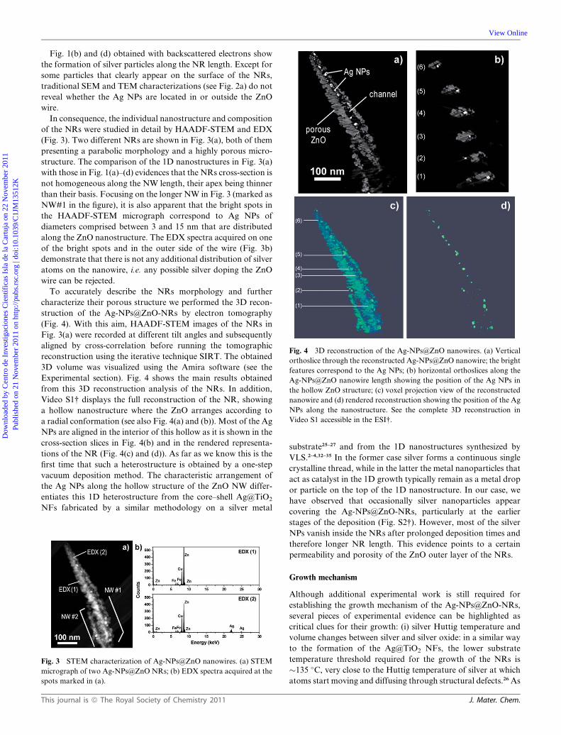
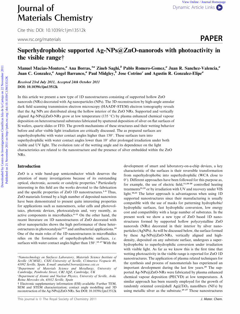
Fig. 4 3D reconstruction of the Ag-NPs@ZnO nanowires. (a) Vertical
orthoslice through the reconstructed Ag-NPs@ZnO nanowire; the bright
features correspond to the Ag NPs; (b) horizontal orthoslices along the
Ag-NPs@ZnO nanowire length showing the position of the Ag NPs in
the hollow ZnO structure; (c) voxel projection view of the reconstructed
nanowire and (d) rendered reconstruction showing the position of the Ag
NPs along the nanostructure. See the complete 3D reconstruction in
Video S1 accessible in the ESI†.
Dow
nloa
ded
by C
entr
o de
Inv
estig
acio
nes
Cie
ntíf
icas
Isl
a de
la C
artu
ja o
n 22
Nov
embe
r 20
11Pu
blis
hed
on 2
1 N
ovem
ber
2011
on
http
://pu
bs.r
sc.o
rg |
doi:1
0.10
39/C
1JM
1351
2K
View Online
Fig. 1(b) and (d) obtained with backscattered electrons show
the formation of silver particles along the NR length. Except for
some particles that clearly appear on the surface of the NRs,
traditional SEM and TEM characterizations (see Fig. 2a) do not
reveal whether the Ag NPs are located in or outside the ZnO
wire.
In consequence, the individual nanostructure and composition
of the NRs were studied in detail by HAADF-STEM and EDX
(Fig. 3). Two different NRs are shown in Fig. 3(a), both of them
presenting a parabolic morphology and a highly porous micro-
structure. The comparison of the 1D nanostructures in Fig. 3(a)
with those in Fig. 1(a)–(d) evidences that the NRs cross-section is
not homogeneous along the NW length, their apex being thinner
than their basis. Focusing on the longer NW in Fig. 3 (marked as
NW#1 in the figure), it is also apparent that the bright spots in
the HAADF-STEM micrograph correspond to Ag NPs of
diameters comprised between 3 and 15 nm that are distributed
along the ZnO nanostructure. The EDX spectra acquired on one
of the bright spots and in the outer side of the wire (Fig. 3b)
demonstrate that there is not any additional distribution of silver
atoms on the nanowire, i.e. any possible silver doping the ZnO
wire can be rejected.
To accurately describe the NRs morphology and further
characterize their porous structure we performed the 3D recon-
struction of the Ag-NPs@ZnO-NRs by electron tomography
(Fig. 4). With this aim, HAADF-STEM images of the NRs in
Fig. 3(a) were recorded at different tilt angles and subsequently
aligned by cross-correlation before running the tomographic
reconstruction using the iterative technique SIRT. The obtained
3D volume was visualized using the Amira software (see the
Experimental section). Fig. 4 shows the main results obtained
from this 3D reconstruction analysis of the NRs. In addition,
Video S1† displays the full reconstruction of the NR, showing
a hollow nanostructure where the ZnO arranges according to
a radial conformation (see also Fig. 4(a) and (b)). Most of the Ag
NPs are aligned in the interior of this hollow as it is shown in the
cross-section slices in Fig. 4(b) and in the rendered representa-
tions of the NR (Fig. 4(c) and (d)). As far as we know this is the
first time that such a heterostructure is obtained by a one-step
vacuum deposition method. The characteristic arrangement of
the Ag NPs along the hollow structure of the ZnO NW differ-
entiates this 1D heterostructure from the core–shell Ag@TiO2
NFs fabricated by a similar methodology on a silver metal
Fig. 3 STEM characterization of Ag-NPs@ZnO nanowires. (a) STEM
micrograph of two Ag-NPs@ZnO NRs; (b) EDX spectra acquired at the
spots marked in (a).
This journal is ª The Royal Society of Chemistry 2011
substrate25–27 and from the 1D nanostructures synthesized by
VLS.2–4,32–35 In the former case silver forms a continuous single
crystalline thread, while in the latter the metal nanoparticles that
act as catalyst in the 1D growth typically remain as a metal drop
or particle on the top of the 1D nanostructure. In our case, we
have observed that occasionally silver nanoparticles appear
covering the Ag-NPs@ZnO-NRs, particularly at the earlier
stages of the deposition (Fig. S2†). However, most of the silver
NPs vanish inside the NRs after prolonged deposition times and
therefore longer NR length. This evidence points to a certain
permeability and porosity of the ZnO outer layer of the NRs.
Growth mechanism
Although additional experimental work is still required for
establishing the growth mechanism of the Ag-NPs@ZnO-NRs,
several pieces of experimental evidence can be highlighted as
critical clues for their growth: (i) silver Huttig temperature and
volume changes between silver and silver oxide: in a similar way
to the formation of the Ag@TiO2 NFs, the lower substrate
temperature threshold required for the growth of the NRs is
�135 �C, very close to the Huttig temperature of silver at which
atoms start moving and diffusing through structural defects.26 As
J. Mater. Chem.

Fig. 5 Superhydrophobicity to superhydrophilicity conversion by light
irradiation. Changes in the water contact angle induced by irradiation
with UV (a) and VIS light (b), respectively.
Dow
nloa
ded
by C
entr
o de
Inv
estig
acio
nes
Cie
ntíf
icas
Isl
a de
la C
artu
ja o
n 22
Nov
embe
r 20
11Pu
blis
hed
on 2
1 N
ovem
ber
2011
on
http
://pu
bs.r
sc.o
rg |
doi:1
0.10
39/C
1JM
1351
2K
View Online
previously shown, at this temperature and under oxidizing
plasma conditions the silver behaves as a molten phase subjected
to strong density changes because of the difference in specific
volume between the silver and silver oxide phases. A suitable way
to release such a surface stress is the formation of whiskers or
segregated NPs. In this regard it is interesting that the mean
diameter of the Ag-NPs inside the Ag-NPs@ZnO-NRs is much
smaller than that of the corresponding silver particles on the
substrate before the ZnO deposition (see also Fig. S1†). (ii) The
parabolic shape of the NRs: the long conical morphology of
the Ag-NPs@ZnO-NRs is a characteristic of the growth of 1D
nanostructures by PECVD because the ions coming from the
plasma phase are selectively focused first on the silver particles
and then on the tips of the growing NRs.37 Lateral inhomoge-
neities in the electrical field distribution associated with the
Ag/ZnO growth must be a consequence of such behavior. (iii)
High homogeneity in the NR length and diameter: even if the
initial silver particle size distribution on the substrate is quite
broad (Fig. S1†), the NR length and diameter are very homo-
geneous (cf. Fig. 1). These two features altogether with point (i)
support the formation during the NR growth of a very mobile
intermediate state of silver/silver oxide similar to a molten phase.
A previous article by Xing et al.38 has demonstrated the effective
growth of ultra-thin ZnO nanobelts in the presence of silver. In
that case the formation of the ZnO nanobelts was produced by
transport and supersaturation of Zn vapor on a 2 nm Ag film at
470 �C. Xing et al. proposed a growth process involving both
substantial precursor migration and effective mass redistribu-
tion, where Ag in its melting state may serve as a soft template to
assist the vapor condensation and the subsequent nanobelt
growth. Although in our case, a plasma assisted process, the
number of factors contributing to the formation of the NRs
increases the complexity of the growth mechanism, a similar role
can be applied to the silver/silver oxide particles. Thus, supported
on the experimental evidence, we tentatively propose a modified
volcano mechanism for the formation of the Ag-NPs@ZnO-
NRs. The main differences between the growth processes of Ag-
NPs@ZnO-NRs and Ag@TiO2 NFs are the different amounts of
silver available for the formation of the core and likely a stronger
influence of the ions coming from the plasma in the case of ZnO
deposition. Under the present experimental conditions the
amount of silver contained in the thin substrate layer is not
enough to produce compact silver wires or threads. However, as
it has been demonstrated by the 3D reconstruction, silver diffu-
sion still occurs inside the nanowire, where silver NPs close to or
at the tip of the NRs seem to favor their vertical growth by
moving in its interior simultaneously to the supply of material
from the plasma phase (i.e., by ‘‘drilling’’ the hollow space inside
the NW). The process occurs in such a way that ZnO grows as
a porous shell while diffusing silver/silver oxide segregates from
the substrate and moves through the interior of the NR. This
surface diffusion is the result of the surface stress produced for
the density changes between silver and the silver oxide (rAg ¼9.32 g cm�3, rAg2O ¼ 7.14 g cm�3) formed in a highly oxidized
plasma environment.26 Once the mobilization and oxidizing
conditions (oxygen plasma and substrate temperature) are
switched off the silver and/or the silver oxide fragments
agglomerate and form the silver NPs that decorate the channel
inside the 1D nanostructure.
J. Mater. Chem.
Wetting behavior
A common approach for the fabrication of superhydrophobic
coatings is the formation of highly rough surfaces of hydro-
phobic or partially hydrophobic materials, i.e. low surface energy
materials.39 Supported nanofiber arrangements have also been
reported to depict a superhydrophobic behavior.23,39,40 Similarly,
the water contact angle (WCA) of a surface formed by a high
density arrangement of Ag-NPs@ZnO-NRs (Fig. 1e) is higher
than > 150� (i.e., superhydrophobic, see insets in Fig. 5). Since
the WCA of a flat ZnO reference thin film deposited under the
same conditions on a Si(100) substrate is �110�, we must relate
the superhydrophobicity found for the NR surfaces to their
highly rough nanostructure,23,39,40 namely with the number of
NRs per unit area, their length and diameter.39,40
The Wenzel and Cassie–Baxter39,41 models try to correlate the
actual WCAs measured on a rough surface with the angle that
would be measured on an ideally flat surface of the same
composition. We have applied the two models to our NR
surfaces and found that while the Wenzel formula does not
account properly for the experimental results, the Cassie–Baxter
model permits to explain their superhydrophobic behavior by
using a quite simple geometrical model to determine the rough-
ness of the samples (see ESI†). The procedure implies the
determination of the solid fraction fS in contact with the drop
under the assumption that, at the interface, water is also in
contact with the air confined between NRs (since the air–water
WCA is 180�). According to this simple approximation the drop
in contact with the surface follows the profile depicted in Scheme
S1 in the ESI†, i.e. the water contact line with the NW does not
reach the substrate. Although a more accurate model should take
into account the shape of the water meniscus, from the simple
calculations gathered in the ESI† we can conclude that the drop
only wets the tips of the NRs and penetrates within the inter-NW
space to a depth of the order of 300 nm.
Previous works have demonstrated that ZnO-NR surfaces
become superhydrophilic (i.e.WCA < 10�) under UV irradiation
because the surface of this material becomes photon activated
and the water may then smoothly spread over the whole internal
surface of the wire structure.10 A similar behavior is depicted by
the system Ag-NPs@ZnO-NRs where the conversion from
a superhydrophobic to superhydrophilic state under UV illumi-
nation is completed after 8 min of irradiation under our
This journal is ª The Royal Society of Chemistry 2011

Dow
nloa
ded
by C
entr
o de
Inv
estig
acio
nes
Cie
ntíf
icas
Isl
a de
la C
artu
ja o
n 22
Nov
embe
r 20
11Pu
blis
hed
on 2
1 N
ovem
ber
2011
on
http
://pu
bs.r
sc.o
rg |
doi:1
0.10
39/C
1JM
1351
2K
View Online
experimental conditions (Fig. 4a). In agreement with ref. 10 and
42 the surface recovered its superhydrophobic character after
keeping the samples in the dark (full recovery after 5 days). A
close look at the WCA evolution in Fig. 5(a) evidences the
existence of an inflexion point at around 2 min which denotes
that a second mechanism has been triggered after irradiating for
this time. A similar superhydrophobic–superhydrophilic
conversion was found when this surface was irradiated with
visible (VIS) light (cf. Fig. 5b). The WCA decreases under the
VIS illumination until reaching a superhydrophilic state (WCA
lower than 10�). Visible illumination is much less effective since
a WCA < 10� is only reached after irradiating for �150 min.
However, this activation process permits the clear confirmation
of the existence of a drastic change in the wetting transformation
process that now is triggered after irradiating for approximately
80 min. Visible light activation of ZnO can be surprising since
this material is a band gap semiconductor which requires UV
photons (E z 3.2 eV) for excitation. However, partial hydro-
phobic to hydrophilic conversion has been found in ZnO and
other semiconducting oxides when irradiated with VIS light in
a process that has been associated with the surface excitation of
surface defect states in the gap.42,43 On the other hand, it is
already established that the deposition of noble metals on
semiconductors promotes an enhancement in their photo-
catalytic activity by indirect influence on the interfacial charge
transfer process.12,13,44,45 In these cases, silver can act as electron
scavenger and charge store. Enhanced photocatalytic activity
has been reported previously for Ag/ZnO systems comprising
ZnO 1D nanostructures decorated with silver fabricated by
different methods.12,13,44 Wang et al.12 have concluded that the
presence of Ag nanoparticles increases the hydroxyl contents at
the surface of ZnO microspheres formed by ZnO nanorods.
Pillai et al.44 have also shown the enhanced photocatalytic
activity for a critical amount of silver in ZnO nanoparticles in
the degradation of rhodamine 6G. Those experiments further
demonstrated that the presence of silver facilitated the interfacial
charge transfer processes in such a way to utilize the conduction
band electrons for enhancing the photocatalytic activity. In
particular, superoxides and OH radicals were formed by the Ag
discharged of the stored electrons into the solution where they
reacted with the dissolved oxygen. Similar excitation processes
can be invoked here with the peculiarity that they lead to
a complete superhydrophilic transformation, probably
promoted by the very particular architecture of the poly-
crystalline hollow Ag-NPs@ZnO-NRs. The 3D tomographic
reconstruction performed by HAADF-STEM has shown that
the ZnO shell presents a highly porous structure (Fig. 4). We can
expect that the ZnO close to the Ag particles behaves as
a superhydrophilic surface because of the enhanced hydroxyl
enrichment under irradiation. It is also important to remark that
for both UV and VIS illumination the inflexion point for the
curves in Fig. 5 is ca. 110�. These results might indicate that the
porous polycrystalline surface of the NRs becomes super-
hydrophilic by gradual conversion of different crystal planes in
a similar way to for the TiO2 surface in the amphiphilic
model.41,46 Once all the different crystal planes are converted the
water contact angle would change drastically by combination
with the photocatalytic enhancement because of the presence of
Ag. Under such conditions the system would partially behave as
This journal is ª The Royal Society of Chemistry 2011
a sponge, implying that the Cassie–Baxter assumptions do not
apply any more.
Experimental section
Sample preparation
Heterostructured Ag substrates are fabricated by DC sputtering
from a 99.99% purity Ag wire in argon (in the range between 1.5
and 2 mbar) at room temperature. Typical substrates were Si
(100) wafers, fused silica, quartz slides and ITO. The hetero-
structured substrates were located in a PECVD reactor for the
deposition of ZnO. The PECVD system consists of a high
vacuum chamber attached to a microwave electron–cyclotron-
resonance (MW-ECR) SLAN I plasma source according to
a downstream configuration, i.e. out of the plasma discharge.
The ZnO precursor, diethyl zinc (DEZ), was purchased from
Aldrich. It was dosed in the vacuum chamber through a mass
flow controller and distributed between the plasma discharge and
the substrate surface by a shower-like dispenser. The Ag-
NPs@ZnO-NRs are formed under oxygen plasma at 4 � 10�3
Torr operated at 400W and a substrate temperature of 135 �C. Inorder to improve the density and homogeneity of the Ag-
NPs@ZnO-NRs, the Ag substrates are first pre-treated in pure
oxygen plasma (4 � 10�3 Torr) at 135 �C for 1 hour.
Sample characterization
Cross-section and normal view SEM images were acquired in
a Hitachi S4800 microscope. GAXRD studies were performed in
an X’Pert Pro from PANalytical for X-ray angles <1�. For theTEM characterization Ag-NPs@ZnO nanowires were removed
from the substrates by scratching and dispersion in ethanol and
then ‘‘fished’’ in a holey carbon grid (from Plano). Bright field
TEMwas carried out in a CM200 from Phillips. HAADF-STEM
electron tomography was performed on a FEI Tecnai F20 field-
emission gun transmission electron microscope operated at 200
kV. Data collection was carried out by tilting the specimen about
a single axis from �64� to +62� with a 2� increment, using
a Fischione ultrahigh-tilt tomography holder, and acquiring the
images with the FEI software package Xplore3D. The tilt series
was then exported to the FEI software Inspect3D for the cross-
correlation alignment and the tomographic reconstruction using
the iterative routine SIRT. Slice viewing and surface rendering
after a global thresholding were undertaken using Amira soft-
ware. Static water contact angle measurements were carried out
by the Young method with droplet volumes of �5 ml with
a CAM100 instrument (KSV Instruments Ltd., Finland). The
samples were irradiated with and without a visible filter with a Xe
lamp. An additional infrared filter was utilized in order to
prevent the heating of the samples. The photon intensity at the
position of the samples was 2 W cm�2 for the UV irradiation
experiments (also including the VIS light photons) and 1.6 W
cm�2 when operated with the visible filter.
Conclusions
In summary, herein we have reported on the PECVD synthesis of
a high density film formed by separated Ag-NPs@ZnO-NRs.
The characterization of these NRs by the HAADF-STEM
J. Mater. Chem.
Dow
nloa
ded
by C
entr
o de
Inv
estig
acio
nes
Cie
ntíf
icas
Isl
a de
la C
artu
ja o
n 22
Nov
embe
r 20
11Pu
blis
hed
on 2
1 N
ovem
ber
2011
on
http
://pu
bs.r
sc.o
rg |
doi:1
0.10
39/C
1JM
1351
2K
View Online
tomographic reconstruction has demonstrated their unique
morphology consisting of a hollow ZnO structure in whose
interior are distributed Ag NPs of different sizes. This
morphology has been discussed in terms of a growth model that
would be a modification of the so-called ‘‘Volcano’’-like mech-
anism proposed previously to account for the formation of
Ag@TiO2 nanofibers. We have also investigated the wetting
behaviour of the Ag-NPs@ZnO-NR surfaces and found that the
surface formed by a high density of NRs presents WCA > 150�.An outstanding property of these surfaces is the possibility to
change its WCA from a superhydrophobic to a superhydrophilic
state by using VIS light, a characteristic that we attribute to the
particular morphology of the NRs and to the incorporation of
Ag NPs in its interior. We expect these results to be of great
interest in microfluidic and photocatalysis in the VIS range.
Acknowledgements
This work was funded by the EU (project NMP3-CT-2006-
032583), the Spanish MICINN (projects MAT2010-21228,
MAT2010-18447 and Consolider CSD2008-00023) and JUNTA
de Andaluc�ıa (projects P09-TEP-5283, CTS-5189). JCG thanks
the Spanish Scientific Research Council (CSIC) for his JAE-Doc
contract (2009-2012) at the ICMSE-CSIC-US. ZS and PAM
acknowledge financial support from the European Union under
the Framework 6 program under a contract for an Integrated
Infrastructure Initiative, Reference 026019 ESTEEM.
Notes and references
1 Z. L. Wang, Mater. Sci. Eng., R, 2009, 64, 33.2 Y. Tak, K. Yong and C. Park, J. Electrochem. Soc., 2005, 152, G794.3 M. Haupt, A. Ladenburger, R. Sauer, K. Thonke, R. Glass, W. Roos,J. P. Spatz, H. Rauscher, S. Riethmuller and M. Moller, J. Appl.Phys., 2003, 93, 6252.
4 D. Ito,M. L. Jespersen and J. E. Hutchison,ACSNano, 2008, 2, 2001.5 J. Elias, R. Tena-Zaera, G.-Y. Wang and C. Levy-Clement, Chem.Mater., 2008, 20, 6633.
6 W.-Y. Wu, J.-M. Ting and P.-J. Huang,Nanoscale Res. Lett., 2009, 4,513.
7 M. H. Huang, S. Mao, H. Feick, H. Yan, Y. Wu, H. Kind, E. Weber,R. Russo and P. Yang, Science, 2001, 292, 1897.
8 M. Law, L. E. Greene, J. C. Johnson, R. Saykally and P. Yang, Nat.Mater., 2005, 4, 455.
9 H. Koga, T. Kitaoka and H. Wariishi, J. Mater. Chem., 2009, 19,2135.
10 X. Feng, L. Feng, M. Jin, J. Zhai, L. Jiang and D. Zhu, J. Am. Chem.Soc., 2004, 126, 62.
11 J. L. Campbell, M. Breedon, K. Latham and K. Kalantar-Zadeh,Langmuir, 2008, 24, 5091.
12 W. Lu, S. Gao and J. Wang, J. Phys. Chem. C, 2008, 112, 16792.13 D. Lin, H. Wu, R. Zhang and W. Pan, Chem. Mater., 2009, 21, 3479.14 H.Koga, T.Kitaoka andH.Wariishi, J.Mater. Chem., 2009, 19, 2135.15 A. Marmur, Langmuir, 2009, 25, 1277.
J. Mater. Chem.
16 M. Ma, R. M. Hill and G. C. Rutledge, J. Adhes. Sci. Technol., 2008,22, 1799.
17 J. Yuan, X. Liu, O. Akbulut, J. Hu, S. L. Suib, J. Kong andF. Stellacci, Nat. Nanotechnol., 2008, 3, 332.
18 B. Kakade, R. Mehta, A. Durge, S. Kulkarni and V. Pillai, NanoLett., 2008, 8, 2693.
19 N. Verplanck, E. Galopin, J. C. Camart, V. Thomy, Y. Coffinier andR. Boukherroub, Nano Lett., 2007, 7, 813.
20 T. N. Krupenkin, J. A. Taylor, T. M. Schneider and S. Yang,Langmuir, 2004, 20, 3824.
21 H. Z. Wang, Z. P. Huang, Q. J. Cai, K. Kulkarni, C.-L. Chen,D. Carnahan and Z. F. Ren, Carbon, 2010, 48, 868.
22 J. Yang, Z. Zhang, X. Men, X. Xu and X. Zhu, Carbon, 2011, 49, 19–23.
23 A. Borras, A. Barranco and A. R. Gonzalez-Elipe, Langmuir, 2008,24, 8021.
24 K. Ostrikov, U. Cvelbar and A. B. Murphy, J. Phys. D: Appl. Phys.,2011, 44, 174001.
25 A. Borras, A. Barranco, F. Yubero and A. R. Gonzalez-Elipe,Nanotechnology, 2006, 17, 3518.
26 A. Borras, A. Barranco, J. P. Espinos, J. Cotrino, J. P. Holgado andA. R. Gonzalez-Elipe, Plasma Processes Polym., 2007, 4, 515.
27 A. Borras, M. Macias-Montero, P. Romero-Gomez andA. R. Gonzalez-Elipe, J. Phys. D: Appl. Phys., 2011, 44, 174016.
28 W. Baumeister, R. Grimm and J. Walz, Trends Cell Biol., 1999, 9, 81.29 P. A.Midgley,M.Weyland andH. Stegmann,Advanced Tomographic
Methods in Materials Research and Engineering, ed. J. Banhart, OUP,Oxford, United Kingdom, 2007, pp. 335–373.
30 C. Kubel, A. Voigt, R. Schoenmakers, M. Otten, D. Su, T. C. Lee,A. Carlsson and J. Bradley, Microsc. Microanal., 2005, 11, 378.
31 P. A. Midgley and M. Weyland, Ultramicroscopy, 2003, 96, 413.32 P. A. Midgley, M. Weyland, J. M. Thomas and B. F. G. Johnson,
Chem. Commun., 2001, 18, 907.33 C. N. R. Rao, F. L. Deepak, G. Gundiahn and A. Govindaraj, Prog.
Solid State Chem., 2003, 31, 5.34 N. S. Ramgir, K. Subanna, Y. Yang, R. Grimm, R. Michiels and
M. Zacharias, J. Phys. Chem. C, 2010, 114, 10323.35 V. G. Dubrovskii, G. E. Cirlin, N. V. Sibirev, F. Jabeen,
J. C. Harmand and P. Werner, Nano Lett., 2011, 11, 1247.36 P. Romero-Gomez, J. Toudert, J. R. Sanchez-Valencia, A. Borras,
A. Barranco and A. R. Gonzalez-Elipe, J. Phys. Chem. C, 2010,114, 290932.
37 I. Levchenko, K. Ostrikov, M. Keidar and S. Xu, Appl. Phys. Lett.,2006, 89, 033109.
38 G. Z. Xing, X. S. Fang, Z. Zhang, D. D. Wang, X. Huang, J. Guo,L. Liao, Z. Zheng, H. R. Xu, T. Yu, Z. X. Shen, C. H. A. Huan,T. C. Sum, H. Zhang and T. Wu, Nanotechnology, 2010, 21, 255701.
39 A. Lafuma and D. Quere, Nat. Mater., 2003, 2, 457.40 A. Borras, P. Groening, J. R. Sanchez-Valencia, A. Barranco,
J. P. Espinos and A. R. Gonzalez-Elipe, Langmuir, 2010, 26, 1487.41 A. Borras and A. R. Gonzalez-Elipe, Langmuir, 2010, 26, 15875.42 V. Rico, C. Lopez, A. Borras, J. P. Espinos and A. R. Gonzalez-Elipe,
Sol. Energy Mater. Sol. Cells, 2006, 90, 2944.43 P. Romero-Gomez, S. Hamad, J. C. Gonzalez, A. Barranco,
J. P. Espinos, J. Cotrino and A. R. Gonzalez-Elipe, J. Phys. Chem.C, 2010, 114, 22546.
44 R. Georgekutty, M. K. Seery and S. C. Pillai, J. Phys. Chem. C, 2008,112, 13563.
45 M. K. Seery, R. george, P. Floris and S. C. pillai, J. Photochem.Photobiol., A, 2007, 189, 258.
46 R.Wang, N. Sakai, A. Fujishima, T. Watanabe and K. Hashimoto, J.Phys. Chem. B, 1999, 103, 2188.
This journal is ª The Royal Society of Chemistry 2011