Study of the Human View
By: Pasi A Linnosto
October 2013
Key Words: Enterprise Architecture, Human View, Generalised Enterprise Reference Architecture and
Methodology (GERAM) Lifecycle and Personnel Pentagon.

Study of the Human View
Pasi A Linnosto Page 1
TABLE OF CONTENT
1. INTRODUCTION 3
2. LITERATUREREVIEW 6
3. METHODOLOGY 17
4. REVIEWOFTHEHUMANVIEW&GERAM 234.1.THENATOHUMANVIEW 234.2.THECANADIANHUMANVIEW 284.3.GERAMLIFECYCLE 32
5. HUMANVIEWMAPPEDTOGERAM 375.1.1. IDENTIFICATION 395.1.2. CONCEPT 435.1.3. REQUIREMENTS 465.1.4. PRELIMINARYDESIGN 595.1.5. DETAILDESIGN 655.1.6. IMPLEMENTATION 695.1.7. OPERATE 715.1.8. DECOMMISSION 73
6. CONCLUSION 75

Study of the Human View
Pasi A Linnosto Page 2
FIGURES Figure 1: Mapping Method .................................................................................................................................... 22Figure 2: NATO Human View Metamodel ........................................................................................................... 24Figure 3: GERAM Life Cycle ............................................................................................................................... 33Figure 4: GERAM Lifecycle Activity ................................................................................................................... 35Figure 5: Requirements to HV Mapping ............................................................................................................... 48Figure 6: HV-3 Standard Figures .......................................................................................................................... 51Figure 7: Risk Bow-Tie ......................................................................................................................................... 56Figure 8: Three Point Estimate .............................................................................................................................. 58Figure 9: Preliminary Design to HV Mapping ...................................................................................................... 59Figure 10: Organisations Personnel Plot ............................................................................................................... 61Figure 11: HV-E Role to Task Mapping ............................................................................................................... 65Figure 12: Detail Design to HV Mapping ............................................................................................................. 66Figure 13: Human Dynamic View schema ............................................................................................................ 70Figure 14: Career Projection Example .................................................................................................................. 72Figure 15: Decommission to HV Mapping ........................................................................................................... 74
TABLE Table 1: HV Outline of the Canadian .................................................................................................................... 29Table 2: List of HV-6 Data Elements .................................................................................................................... 31Table 3: Human View Reference Chart ................................................................................................................. 38Table 4: System HV-2 Establishment Model ........................................................................................................ 46Table 5: System Requirements and HV-9 Human Tasks ...................................................................................... 49Table 6: HV-4 model for ATM site-A ................................................................................................................... 52Table 7: HV-8 Risk Assessment Table .................................................................................................................. 57Table 8: HV-5 Physical Characteristics Flight Strip Control ................................................................................ 62Table 9: Sample HV-5 model for RAPCON Operator .......................................................................................... 63Table 10: Canadian HV-5 Example ....................................................................................................................... 64Table 11: List of Acronyms ................................................................................................................................... 78

Study of the Human View
Pasi A Linnosto Page 3
1. INTRODUCTION It is assumed that all engineered systems have a human aspect and it’s difficult to think of a system that does not
need a human element to exist. Every system from piloted to unmanned aircraft, a bank’s deposit system, to the
standalone ATM requires people to design, build, maintain and control its function during its life history;
therefore it is difficult to think of any system that doesn’t need some form of human interaction during its life.
The reason why we study the human element in Enterprise Architecture (EA) is because humans play a
significant role in the system. The significance of the human element can be calculated as a cost Handley
concluded in one of her papers’ by stating that “Over the life cycle of most system the human element is
considered the most costly resource” (H. Handley & Smillie, 2010), and the efficient use of resources within a
system can reduce cost across the enterprises’ lifecycle. By ignoring the human element we risk developing
flawed systems.
In July 2007 the North Atlantic Treaty Organization (NATO) Research and Technology Organisation created a
panel to discuss the purpose of multi nation human activities and the role they play in a system. The panel was
named “Human Factors and Medicine Panel 155” was formed to workshop this idea and develop a way to
explicitly represent of unique human attributes. The result was a NATO-wide Human View (HV) model
independent of any specific architectural framework. Because the study into Human Views is relatively new to
the defence Enterprise Architecture frameworks, most of the current military frameworks do not have the
panel’s findings incorporated into their frameworks and therefore do not adequately account for the human
element in their lifecycles (H. Handley & Smillie, 2008). By continuing the study into human view products and
elements, the participants have refined the original NATO findings to a form that could be used to complement
other established defence frameworks such as the Department of Defence Architectural framework (DoDAF)
(Defense, 18 May 2009), Ministry of Defence Architecture Framework (MoDAF) (MoD, 2008) and Department
of National Defence and the Canadian Forces Architecture Framework (DNDAF) (Framework, 2011).
The motivation for conducting this study came from the defence frameworks failure to capture human-centric
design aspects for systems operation and maintenance (H. A. Handley, 2012). The evolution of the study into
Human View for Architectural Frameworks for the military followed with the idea of incorporating elements
and viewpoints for the human aspect into other architectural frameworks.

Study of the Human View
Pasi A Linnosto Page 4
Research on the Human View (HV) has predominantly been carried for the defence industries to partially map
Human Views to existing Architectural frameworks including MoDAF (Bruseberg, 2010), DoDAF (H. A.
Handley, 2012) and DNDAF (Coats C, 2013). These efforts delivered ontological models (in form of
metamodels, but not full blown ontological theories), which can be used to mandate specific model types to
populate the human view of the system of interest. The question is therefore, weather non-military Architectural
Frameworks are amenable to use of these human view related concepts, and is so how?
The specific aim of this paper is to take one further step and discover if the ongoing study into Human View is
adaptable to the GREAM lifecycle framework, given its status as the ISO 15704 standard, which describes the
requirements that architectural frameworks should satisfy. To clarify the question: while ISO 15704 clearly
mandates the representation of the human element on an equal footing to the automated element of a system, the
question remains how the Defence Architectural Frameworks’ new development relates to this requirement.
The reason for selecting an enterprise architecture framework for mapping was to cover the widest possible
range for human activities and human interaction across the entire life cycle of the system of interest. During an
enterprise lifecycle the human elements (people / employees / enlisted personnel) will be called upon to plan,
execute, test, monitor and complete actions on the system; therefore the current study into human views should
consider all human activities that take place during the lifecycle of an enterprise. An enterprise lifecycle (i.e. the
lifecycle of the enterprise-as-a-system) comprises many system lifecycles (FAWG, Feb 2001) and it is not
possible to discuss in detail all types of system lifecycles in one dissertation; therefore this study will map
existing HV elements to the GERAM Lifecycle activities and give examples using an Air Traffic Control
System as one example of a system lifecycle where practical examples are needed.
The goal for mapping the HV into a GERAM Lifecycle will be to see if the current study into Human Views is
complete, by mapping human elements to lifecycles an established framework entity such as the ones illustrated
in GERAM. The reason for choosing GERAM as the preferred EA framework was because it mandates the
consideration of both Human and Machine elements in each lifecycle activity for each entity in the enterprise
(called ‘enterprise entity’ in GERAM), thereby enabling this research to be affixed to an established EA
baseline.
A number of HV studies will be considered during this study before selecting the most suitable and
comprehensive Human View concepts to map. (Later in this dissertation we may refer to ‘Human View

Study of the Human View
Pasi A Linnosto Page 5
entities’, meaning the human view related concepts in the human view ontology, this is not to be confused with
the concept of ‘enterprise entity’).
The technique used in this paper can be described as Conceptual Analytical Research (Järvinen, 2004). Because
the research compares concepts by using logical arguments and analytical thinking, along with established an
architectural framework (GERAM lifecycle), with the theoretical findings of Human Views research performed
by military architectural framework developers.
This paper will advance the research in Human Views by identifying gaps in the current study suggest clearer
methods or approaches to aid understanding of what is required in each Human View. The answer is likely to
i) Shed light on possible further development that may be needed for ISO15704 and GERAM; and
ii) Identify possible gaps of completeness in the effort of Defence Framework developers, thus the
conclusion of this dissertation may be of use for both communities.

Study of the Human View
Pasi A Linnosto Page 6
2. LITERATURE REVIEW This study will review several efforts to incorporate the Human View (HV) and Architectural Frameworks with
the focus being on the human element in the system, including:
• Human View Products developed by Defence Research and Development Canada (Defence R&D
Canada).
• Generalised Enterprise Reference Architecture and Methodology (GERAM) Version 1.6.3 of 1999,
which is also Annex to ISO15704
• North Atlantic Treaty Organization (NATO) Human View (HV)
• Human View for Ministry of Defence Architecture Framework (MoDAF), United Kingdom
Other HV ontological (and associated views), which formed part of Handleys’ earlier work (H. Handley &
Smillie, 2008) were also reviewed but, not used in this thesis because of their lack of available detailed material.
Ø Maritime Headquarters with Maritime Operations Centre (MHQwMOC) Concept Based Assessment
US
Ø Royal Netherlands Navy (RNLN) Manning Program
Ø Human Systems Integration Human View Dynamic Architect (HIS HVDA) US
Terms used in Enterprise Architecture are not always easily understood. For the purpose of clarification the
following section will define commonly used in the paper and expand on their definition.
Architecture is defined in ANSI/IEE Std 1471-2000 as, “The fundamental organization of a system,
embodied in its components, their relationships to each other and the environment, and the principles
governing its design and evolution”. Architecture is also defined as, “the structure of components, their
interrelationships, and the principles and guidance governing their design and evolution over time” (IEEE
1990) (Stewart, Baker, Pogue, & Ramotar, 2008).
DNDAF Version 1.8 defines Enterprise Architecture as “A collection of strategic information that defines
a business, the information and technologies necessary to operate the business, and the transitional

Study of the Human View
Pasi A Linnosto Page 7
processes necessary for implementing new technologies in response to the changing needs of the business.
It is represented through a set of integrated blueprints” (Annex A p13 (Framework, 2011)).
Human Factor Integration (HFI) in the UK, which is the same as Human System Integration (HSI) in
the US, puts people at the centre of attention. The main question asked by practitioners in this field is, “Can
this person/these people, in this job, with this training, perform these tasks, using this equipment, to these
standards, under these conditions?” HFI is a bottom up structure; with the exception of the so-called
‘cognitive work analysis’ (CWA: Vicente 1999: Naikar et al 2003) (Paragraph 3.5 p27 (Bruseberg, 2010)).
Systems Engineering (SE) there are twelve systems engineering roles described by INCOSE. Of the
twelve roles five are Life-Cycle roles and five are Program Management roles, the remaining two are
neither (Sheard, 1996), each of the twelve roles or billet’s are described as a job that has a defined structure
with a one-to one correspondence. Billets may be allocated amongst a group on system engineers who
specialise in a subsystem or a software component. For example, architects ask (and respond to) the
question “ Can these capability requirements be achieved through these operational
activities/nodes/information networks, fulfilled with these technology functions and structure, over these
timescales, given these connectivity standards, technology trends, and organizational structure?”(Paragraph
3.5 p27 (Bruseberg, 2010)).
Architectural Viewpoint: systems of interest need to be considered by various stakeholders, each with a
set of concerns regarding the system. An architectural viewpoint (as defined by IEEE 42010:2011, and
GERAM v1.5 (Bernus & Noran, 2010)) can be used to determine what representation of the system and to
what level is appropriate to answer such stakeholder concerns. The content (or type) of models, which are
necessary to give answers to the questions defined by the viewpoint can be expressed using an ontology that
is often expressed as a metamodel.
A particular set of concerns is the consideration of the role of the human in the system, and may be called a
‘Human Viewpoint’ (using ISO42010 terminology), or using old terminology ‘Human View’ (see below).
An Architectural Product is a specific representation of a particular aspect of that perspective and
typically represented by graphical, textural and tabular items that result from the process of building the
architectural description or model (H. Handley & Smillie, 2008).
Study of the Human View
Pasi A Linnosto Page 8
An Architectural View represents a perspective on a given architecture (H. Handley & Smillie, 2008), as
required to be seen by a stakeholder who needs answers to some particular set of concerns.
It is also important to note that an Architectural View will consist of one or more Architectural Products (H.
Handley & Smillie, 2008).
Human View’s (HV) provide a link between SE and HFI combining the two together. A model that is
populated with architectural data is called a view. An organised collection of views is given the name
viewpoints (H. Handley & Smillie, 2008).
According to (H. Handley & Smillie, 2008) an “Architectural framework defines a common approach for
development, presentation and integration of architectural description”. However it is important to note that
using the same architecture framework in different context (different stakeholders and concerns) the actual
architecture viewpoint, products and views may be markedly different, and consequently so would be the
ontologies to be adopted.
The history of Enterprise Architecture in the defence context began in 1996 when the US Department of
Defence Architectural framework was derived as the foundation of a method to design and commission large-
scale system engineering projects. Other nations also developed similar Architectural frameworks to DoDAF
specific for their own military needs such as the Ministry of Defence Architectural Framework United
Kingdome MoDAF and Canadian Department of National Defence Architectural Framework DNDAF.
Typically, these frameworks adopted an integrated metamodel based on the typical architecture viewpoint
considered important for the design and commission of large-scale system engineering projects and their
products. By developing integrated metamodel EA practitioners are able to ensure that data elements defined in
one architectural product are considered in other applicable products. Linking the viewpoints and views in this
fashion ensures that everything is considered for the entire project (H. Handley & Smillie, 2008).
A literature review of the NATO HV metamodel was conducted to find common descriptions for elements that
could be used during the Mapping phase of this paper.
The history of the study into Human View came about with the introduction of a NATO Human View
metamodel that sort to include the Human aspect of systems that was missing in these architectural Frameworks.

Study of the Human View
Pasi A Linnosto Page 9
The NATO RTO HFM 155 Human View Workshop panel was formed to formulate an approach to include
Human factors into current Enterprise Architecture (H. Handley & Smillie, 2008).
The Panel’s aim was to document the unique implications humans bring to the system design, which in turn
provided the following five benefits to including the Human View into Enterprise frameworks:
• Enables an understanding of the human role in enterprise architecture
• Provides linkage between manpower, personnel, training and human communication
• Early recognition of human effort in the system being proposed
• Universal acceptance of human elements across international forces
• An improved framework provides a more complete set of attributes for system data.
The results of the NATO RTO HFM 155 Human View Workshop in July of 2008 were the creation of a Human
View (point), which will be discussed in greater detail in section 4.1 of this paper.
In 2004, there was an attempt to incorporate human aspects into Operational View products, as well as similar
attempts both in Canada and the United Kingdom to include Human activity as part of their frameworks was
made. HFI’s were consulted to add manpower, personnel, training, and business factors engineering aspects to
the study. The addition of Dynamic models then showed how the model would change over time and respond to
external stimuli (H. Handley & Smillie, 2008).
The first attempt to utilise the NATO HV model was to build elements that complement MoDAF, to assist in the
creation of a socio-technical system.
The results of the study suggested the inclusion of seven (7) initial elements to represent the Human View (H.
Handley & Smillie, 2008) which are as follows:
HV-A. Capability Constraints - the impact on the system from human factors, ie work hours, training
human endurance.
HV-B. HFI Quality objectives and metrics – A repository of priorities, values and performance criteria to
metrics and targets.
HV-C. Social network structure – Information exchange between human-human, groups and teams.

Study of the Human View
Pasi A Linnosto Page 10
HV-D. Organisational dependencies – The individuals positions in the organisation what he/she can and
cannot do.
HV-E. Human function definitions – Defines specific human functions in the system.
HV-F. Human functions to role and competency mapping – Specified requirements and high-level
solutions for Human Resources.
HV-G. Human performance dynamics – Creates predictions, or a set of predictions, for external stimuli
and career growth.
For the next NATO HV model the panel consisted of many different country representatives; all of who used
different architectural approaches tailored to their individual needs. During the workshop similarities between
the architectural approaches were collected to form the NATO Human View products.
The purpose of the NATO Human View is to define human centric roles in a system, by creating a repository of
human operation activities, tasks and communications to complete a task to supports the operational
requirements.
Ms Anne Bruseberg was the next evolution of the Human View metamodel in 2010. The paper significantly
expanded the understanding of Human View with an aim to build elements that complement MoDAF that
would assist in the creation of a socio-technical system (Paragraph 4.1 p31 (Bruseberg, 2010)).
The NATO HV Metamodel discussed in this paper was published by Ms Anna Bruseberg in 2010 for BAE
systems (Bruseberg, 2010). The publication aligns the NATO HV Metamodel to MoDAF and are as follows: -
HV-A. Personnel Availability
HV-B. Quality Objectives and Metrics
HV-C. Human Interaction Structure
HV-D. Organisation
HV-E. Human Functions and Tasks
HV-F. Roles and Competencies
HV-G. Dynamic Drivers of Human Behaviour.

Study of the Human View
Pasi A Linnosto Page 11
The NATO HV Metamodel described by Bruseberg has three (3) distinct groups. The first group refers to the
Human Structure and Process and combines HV-A, HV-D to HV-F. The second group refers to the human
aspects of technology and infrastructure (i.e. what to build), which is described in both HV-C, HV-E. The third
group refers to the overarching design aspects in HV-B and HV-G (Page 31 (Bruseberg, 2010)).
Bruseberg described each of the seven NATO viewpoints (Part 2 Table 8 & Section 5.3 to 5.7 (Bruseberg,
2010)) as follows: -
i. The first NATO viewpoint is HV-A Personnel Availability and as the name suggests the central question
asked is, Who could be made available and what personnel process is required?
Bruseberg conducts an analysis in HV-A and defines requirements and formal processes to ensure that
actual people with the right characteristics and in the right numbers are available to fill human roles as part
of a posting or a job.
The HV-A element can be used as a starting point to integrate Human Viewpoints into an existing
Architectural framework’s mandatory metamodel or audit an entity and improve human aspects.
The HV-A viewpoint can also used to determine at the onset what capabilities are available within the
organisation thus highlighting any shortcomings. There may be an excess of employees in the organisation
or a deficiency.
ii. The second NATO viewpoint HV-B Quality Objectives & Metrics asks the central question asked is, How
may human related benefits be expressed and measured? We conduct analysis of HV-B to create a higher
level, specifying the non-functional human-related design objectives in support of the enterprise metrics,
which is critical to cover all needs and to drive HF design efforts from early stages.
Again HV-B is not a good starting point for beginning a project because it requires functional inputs to
analyse. In this view defining suitable quantifiable metrics early is essential for non-functional requirements
specification, and updating is needed as more information becomes available.
iii. The third NATO viewpoint HV-C Human Interaction Structure asks the central question, What are the
human integration structures to be supported by technology solutions? We conduct analysis of HV-C to
discover potential role interaction requirements as the foundation for defining the need for technology
supporting information use, transfer and sharing.

Study of the Human View
Pasi A Linnosto Page 12
HV-C provides high-level structural requirements primarily in response to location constraints.
iv. The fourth NATO viewpoint HV-D Organisation asks the central question, What are the required changes
to formal organisational structures and processes? We conduct analysis of HV-D to understand current
post definitions, rank and structure along with unit and team membership.
v. The fifth NATO viewpoint HV-E Human Function and Tasks defines roles between Human and Systems
and asks the question, Which human activities are to be supported by technology functions, and how should
humans and technology complement each other? We conduct analysis of HV-E in order to balance
automation decisions and as the basis for either human design requirements or equipment requirements.
If a human task is not understood the role cannot be defined. Human behaviour metrics are grounded in
human tasks.
vi. The sixth NATO viewpoint HV-F Roles and Competencies asks the central question, Which human role,
skills and characteristics need to be supported, based on the task demands? We conduct analysis of HV-F
to define roles and formally organise post definitions.
vii. The seventh and final NATO viewpoint HV-G Dynamic Drivers of Human Behaviour asks the central
question. What are the time structures, conditions, and scenarios to be supported for different
configurations? We conduct analysis of HV-G to design human related dynamic properties and constraints,
which are closely intertwined with all other design decisions.
A literature review of the Canadian HV metamodel was conducted to find common descriptions for products
that could be used during the Mapping phase of this paper. Some of the publications about Human View
products are not readily available to the public; the most current information is still under development and was
sourced from the Canadian Department of Defence as draft documents.
In 2008 the first Canadian human view metamodel was built for DNDAF under a defence contract and
contained four elements HV-1 to HV-4 (Stewart et al., 2008):
HV-1. The manpower projections – Illustrates the predicted manpower requirements for supporting
projects and programs.
HV-2. The Career Progression Roadmap – Illustrates the potential career progression in the field.

Study of the Human View
Pasi A Linnosto Page 13
HV-3. The Individual Training Roadmap – Architectural product illustrates the instruction or education
needed to provide individual employees their job requirements.
HV-4. The Established Inventory – defines the current number of military personnel by rank and job
within each CF establishment.
The 4 products are interdependent; however HV-4 is used to forecast HV-1. Similarly HV-2 and HV-3 products
are interdependent because career path may anticipate job requirements.
The Canadian HV metamodel presented a compact approach to HV while still implementing many of the
previous HV viewpoints found in the NATO Metamodel.
The Canadian approach to Human View was to limit the number of HV products in the architecture and
specifically target decision perspectives on manpower, career progression and training. The intent of these
changes was to help define and describe the role of the human within the system (Stewart et al., 2008).
The System perspective: How do humans impact the system’s automated component?
• Mission performance, safety, supportability and cost
The Human perspective: How does the automated component of the system impact the human component?
• Trade structure, skill gap and training requirements, manning level, career progression, selection and
retention, workload and morale.
The first Defence R&D Canada publication described each of the four Canadian elements as (Stewart et al.,
2008):
i. The first viewpoint HV-1 describes manpower projections; this illustrates the predicted manpower
requirements for supporting projects and programs.
Manpower projections are represented using a Gant chart to show all project groups planned along with
system groups, planned projects.
This information can be used to determine the amount of manpower required by the organization over the
years.

Study of the Human View
Pasi A Linnosto Page 14
ii. The second viewpoint is HV-2 the Career Progression Roadmap – Illustrates the potential career
progression in the field.
The first step in producing a career map for the program is to define product data elements for each ‘job’
for decision makers to determine an appropriate strategic career path for personnel in the organization.
The Canadian Military used Military Occupational Structure Analysis, Redesign & Tailoring Project
(MOSART) to create a structure a roadmap. The same approach may not work as easily in civilian life
because people have the freedom to change employers.
iii. The third viewpoint is HV-3 the Individual Training Roadmap – this Architectural product illustrates the
instruction or education needed to provide individual employees their job requirements.
1. Identifying what an individual learns to meet requirements of the task and duty
2. Define performance objectives
3. Determine a learning suitable programed, and environment
4. Identify those who need the qualified learning
When considering learning we also need to determine what contributions learning will make to the project,
and weigh that against cost of the project.
Across the life of the project how will the learning program change, what can be training, what can be
reused and can we leverage off other programs with similar training.
iv. The fourth viewpoint is HV-4 the Established Inventory – defines the current number of military personnel
by rank and job within each CF establishment.
1. The HV-4 product is used to
2. Support forecasting for training
3. Personnel availability. To identify the right person at right time with the right qualifications
Identify gaps in personnel availability, which can be addressed through training, transfers and recruitment
drives.

Study of the Human View
Pasi A Linnosto Page 15
For the organisation the total number is often constrained by the Total Paid Strength (TPS) number, which
translates into the amount of budget the organisation, has for the project. It is not cost effective to have an
oversupply of human resource on a single project, or to have an oversupply of personnel waiting to be assigned
an activity. HVs will need to support decision-making on this trade-off allowing the explicit consideration of
supportability of programs across the organisation.
The four viewpoints in the Canadian metamodel are now being superseded by an updated version with ten
elements. Note that NATO and Canadian Human Views discussed in this chapter were eventually not
considered adequate and complete to map into the generalised architectural framework. Although Bruseberg
found that the NATO HV model presented was compatible with MoDAF, I was unable to map the model to
GERAM because they did not possess critical elements described in the first NATO HV Metamodel such as the
Concept element. For this study I used the first NATO Human View model in Section 4.1 and the Canadian
Human View in section 4.2 to map to the Enterprise lifecycle of GERAM described in section 4.3. The method
used to do the mapping is described next in the Methodology section of this paper.
The final part of the literature review was conducted on Handleys’ publication which mapped HV to select
DoDAF viewpoints (H. A. Handley, 2012). In this study Handley was using a ‘data based approach’ with a
focus on data needed to design the system. Architectural products from previous versions were referred to as
models and range from spread sheets, documents, and graphs that make the information easier to understand for
the recipient (because it was in a format common to what was previously used). The Human View would
provide an additional viewpoint in the DoDAF 2.0 model, suggesting that DoDAF 2.0 did not adequately
represent the HV in its current form.
Handley explains that ‘the DoDAF Meta Model (DM2) provides a high-level view of the data normally
collected, organized and maintained in an Architectural Description’.
The DM2 has three (3) levels of abstraction:
1. The Conceptual Data Model (CDM) – high level data
2. The Logical Data Model (LDM) – which adds technical information for clarity
3. The Physical Exchange Specification (PES) – Data types and implementation attributes

Study of the Human View
Pasi A Linnosto Page 16
Handley work focuses on CDM to incorporate HV into DoDAF Version 2.0 which is understandable, because it
is normally only for the automated part of the system of interest that an exact specification is necessary of the
form of representation (LDM and PES); for human-interpreted information the conceptual definition has
primacy, the form of representation is often, but not always, less important (e.g. take for example multinational
forces).

Study of the Human View
Pasi A Linnosto Page 17
3. METHODOLOGY As described during the introduction of this study the technique used in this paper is a conceptual analytical
research method (Järvinen, 2004). Normative examples will be used throughout the paper to describe the ‘as is’
HV element mapped to the ‘ought to’ GERAM lifecycle activity and its deliverables. This means that during the
mapping exercise in section 4, the study will examine each HV element against an established Architectural
Framework (the ‘GERAM lifecycle’) to determine if the HV element description is complete or if the HV
element requires additional information to comply with the GERAM / ISO 15704 requirements.
In my research, an initial attempt was made to gather real data, by analysing an upcoming project with the
Australian Defence Department AIR5431 (Defence, 2013) The AIR5431 project is a three phase project to
replacement for the existing Australian Defence Air Traffic System (ADATS), however due to constraints
outside of my control I was unable to attain some of the data.
After reviewing several HV metamodels in section 2, it is now possible to begin the exercise of describing the
main components of the HV study to be mapped to the GERAM Lifecycle.
Before this is done, it has to be clarified what is the relationship of the EA framework (such as GERAM) and
the metamodel(s) investigated.
An EA framework specifies the scope of modelling: e.g. GERAM/ISO 15704 mandates that all aspects of
enterprise need to be representable, whether implemented by automated means of by humans, including
anything done to perform the enterprise’s mandate (the ‘service’), or its management, and whether it is done by
‘hardware’ (i.e., the human with available skills and knowledge) or ‘software’ (i.e., the instructions, policies,
etc.) that control the performance of the human action.
This scope definition does not, however, mandate any particular HV metamodel – it only mandates that for any
particular context one must have a metamodel covering the concerns of stakeholders, and allowing an
integration of facts across architecture viewpoints.
The next section of the study (4) will review the NATO and Canadian Human View metamodels and relate it to
the scope definition of the GERAM lifecycle model. At the time this study was conducted the Canadian Human
View metamodel (selected as most relevant) was still under development. As a result the HV elements were
changed from the original 2008 model (Stewart et al., 2008) for the 2013 model (Coats C, 2013). It is important

Study of the Human View
Pasi A Linnosto Page 18
to note that the 2013 model was in draft during the development of this paper and that it could change in the
future. Descriptions from 2008 were applied (where applicable) to the 2013 model where clarification was
required, for instance the individual training roadmap described in HV-3 in the 2008 paper shares similarities
with the 2013 HV-6 training needs and could therefore be utilised to gain a better understanding of training
needs. Again sections from each paper were used to elaborate on the Human View element being described in
the mapping of the HV to GERAM.
The next section (5) will map the human view elements to the GERAM framework and describes how the
militarised NATO military HV and the Canadian HV models related to the GERAM Lifecycle model. During
the mapping exercise attention will be drawn on any gaps in the current study of the human view in military
AFs.
The inclusion of Human View elements into any enterprise lifecycle cannot be viewed as a one size fits all
exercise. GERAM gives us a method to consider many different viewpoints to building or improving a system
throughout its enterprise lifecycle.
Human View elements are considered somewhat independent to one another, that is to say there is no particular
HV element considered to be a starting point or a formal sequence of events the architectural practitioner needs
to follow. However some HV elements do rely on information established in other views as a prerequisite to
completion. Relevant information may already exist in other parts of the organisation and can be used to support
creation of architecture descriptions and, where this is the case we needn’t reproduce the work if it is deemed
adequate by the EA model.
Refer to Figure 1 to see the logical organisation of HV elements between four levels of a lifecycle. Each slither
(level) represents a phase of the lifecycle. ‘Decision level’ incorporates Identification and Concept lifecycle
activities of the GERAM lifecycle.
Essentially, the HV architecture descriptions (products) are produced by life cycle activities, and as such
mapped as deliverables onto the GERAM life cycle.
The main components (HV products) considered in the decision level are HV-1 and HV-2 that is shown grouped
together in a circle.

Study of the Human View
Pasi A Linnosto Page 19
The second slither concentrates on the Requirements lifecycle activity in GERAM; again the main products are
HV-3, HV-4, HV-8 and HV-9.
The next slither groups GERAM Preliminary Design (or architectural design) and Detailed Design having HV-
5, HV-6, HV-7 and HV-10 as the main components.
The Manufacture and Operate slither incorporates Build and Operate life cycle activities in the GERAM
lifecycle and captures the NATO HV elements HV-G, HV-H and HV-B2.
The final slither is named Decommission or Replacement has no new HV elements identified, however all HV
elements can be considered depending on the scale of activity and the specifics described in a replacement plan.
The decommission slither is a potential extension target for an integrated defence AF’s metamodel.
Human view elements are present on several levels of the lifecycle model. During the decision level shown in
Figure 1 HV-1 Concept and HV-2 Establishment are the main elements, but we need to also be cognisant of
certain elements within HV-4, HV-9 and HV-10.
Some aspects of HV-4 Manpower Projection have an impact on projects size. Corporate support entities, like
Payroll and Human Resources, provide a service on behalf of an organisation to maintain a healthy work
environment. The difference between supporting a small project with ten people and supporting a large program
with fifty people needs to be identified at the decision level to gauge the level of rigour needed during the
lifecycle. For instance a corporation can apply a monetary test to projects to gauge the level of involvement
necessary. A project below $100k may commence with departmental approval, and projects over $100k require
CEO approval, and projects beyond $1M would need board approval before company commitment can be
made.
Some aspects of HV-9 Human Task need to be considered at the decision level to see if the project is viable,
given strategic direction. Consideration needs to be given at senior levels to determine if the project lies within
the scope of the expertise. An extreme example would be a machine manufacturing company would not
consider diversifying into banking because the staff knowledge and skill requirements are vastly different.
The transmitting of information between people on the project is initially considered in the decision level and
later at the design level. Efficient communication HV-10 ensures people working on the project have the ability
to exchange instructions and ideas easily. For example a company with many offices in different states may
Study of the Human View
Pasi A Linnosto Page 20
have skilled management in one city, separate to its primary workforce in another city. This limits their ability
to communicate via emails and telephone but is necessary to understand the cost implications. By merging the
two disciplines into one facility may improve communication but at what cost. High-level HV-10
communication metamodels need to be set up during the Decision level phase of a project.
Later in the Design phase HV-9 Human Task will be refined to accommodate the specific needs of the project.
Personnel will need to adopt new roles and carry out new tasks possibly with a different toolset. For instance an
IT Internet business acquires a project to implement change from Lotus notes to Windows based email. The
Information Technician will need to acquire new skills to work in a Windows based environment.
On the requirements level of the HV-5 Personnel Characteristics along with HV-6 Training, need to be captured
as requirements are verified against the design later during the test phase.
Requirements for physical, sensory and psychological characteristics in HV-5 are captured to identify specific
human skills needed to operate equipment. For example personnel working as ‘Flight Data Controllers’ needs to
exhibit a psychomotor skill to type a twenty-five-letter code into a desktop computer every time a flight strip is
presented by the machine interface. The accuracy needed to reproducing a flight strip is critical; therefore each
reproduction of the flight strip needs a cursory check by a controller before he/she can act upon the command.
In order to minimise the need to correct problems a Flight Data controller needs to produce X amount of flight
strips in Y amount of time with 98% accuracy.
The development of a new system may require some training, not only for the contractor but also for the
customer. Any specific requirements for training needs identified in HV-6 can be captured here.
Requirements set out for HV-9 Human Task will be refined in the design level. As the system is being designed,
refinements to the human interface may be made. For instance during design the developers discover that an
automated system will halve the workload for the human operator checking licence information on a system.
The improvement to the system changes a job description from tracking licences on a system from a four hour
task every month to a one hour task every three months.
On the Design level HV-7 System Safety is considered and then applied and maintained in testing and
manufacture. System developers are cognisant of designing safe systems however this is not always as
straightforward as it sounds, the designs of a system can be inherently unsafe. Take for instance a pair of
scissors; the design of the scissor is inherently unsafe only the correct use of the design will ensure safety. The

Study of the Human View
Pasi A Linnosto Page 21
same would apply to manufacturers in defence armament, which are designed to be unsafe to the enemy;
therefore HV-7 System Safety needs to be considered on Design/Test and monitored during the
Manufacture/Operate level.
The final level described in this paper deals with the decommissioning or replacement of the system. Lessons
learned throughout the system lifecycle should be captured and studied before embarking on a replacement
program. The decision to replace a system may be considered in the operational stage of a system lifecycle, the
customer monitoring the effectiveness of the system can make a determination when the existing system needs
to be decommissioned and if necessary replaced (partially or entirely). The same needs to be considered with the
human view; to what level will humans play a role in the next generation system? From conclusions drawn at
this point in the lifecycle, new Identification and Concepts will be formulated, repeating the system lifecycle
activities once again.
Legal descriptions such as Federal, State and Local Government policy along with Military Policy and Doctrine
along with some Occupational Structures and Job Descriptions are not discussed in this paper. System Safety is
not described in great detail because it can be specific to the individual countries’ legislation. Safety will be
discussed generically but ultimately it should be tailored to each location because this study deals with
Enterprise models that can be adopted in any country.
The Human View products have been adopted for program and project oriented work. Corporate entities such as
Human Resources, Finance, Legal services and Leadership positions at the corporate level are referenced for
their existing best practice applications, but not included as activities to be included in this study, and it is
possible that the metamodel and associated architecture descriptions / models would have to be extended to be
able to describe the human aspect of such enterprise activities.

Study of the Human View
Pasi A Linnosto Page 22
Figure 1: Mapping Method

Study of the Human View
Pasi A Linnosto Page 23
4. REVIEW OF THE HUMAN VIEW & GERAM Two Human View metamodels the 2008 NATO Human View Metamodel devised by NATO RTO HRM-155
Human View Workshop 2008 (H. Handley & Smillie, 2010) and the most recent Canadian Human View (Coats
C, 2013) are to be examined and mapped against GERAM in this study. Specifically, these two HV metamodel
elements and associated work products, will be examined and mapped to the GERAM Lifecycle model (Bernus,
Nemes, & Schmidt, 2003). This chapter will examine the NATO elements and Canadian HV products along
with GERAM Lifecycle activities prior to mapping them in chapter 5.
4.1. The NATO Human View The NATO Human View Metamodel considered in this paper will be based on the NATO Metamodel described
by the NATO HFM 155 Panel in (H. Handley & Smillie, 2008) paper. Figure 2 shows a graphical representation
of the NATO Human View and describes how each product interacts with others. The interaction between the
two HV metamodels (NATO HV metamodel and the Canadian HV metamodel) are not discussed in great detail
in this paper, instead products from NATO HV are used to reinforce the understanding of the Canadian HV
elements.
The HV-A Concept product of the Human View is considered as the starting point in Figure 2. It represents a
high level component of the architecture description, to visualise and facilitate the understanding of the human
aspect of the system under consideration. The aim is to understand how the human element will impact the
system performance, and to incorporate the human element into system design for operational context (pages
161-163 (H. Handley & Smillie, 2008)).

Study of the Human View
Pasi A Linnosto Page 24
Figure 2: NATO Human View Metamodel
Elements of HV-A include:
• A graphical or pictorial presentation of the human element in the system
• A high level Interface Control Document (ICD) for human machine interaction
• A textural description of the overall human component of the system.
HV-B is the Constraints product that lists the operational human limitations within the system. The reason why
we need to consider constraints is because of the expectations of a design that may exceed the human operator
limitations. This product derives a set of constraint that needs to be documented and understood prior to the
system being developed (page 161).

Study of the Human View
Pasi A Linnosto Page 25
The sub products of HV-B include:
HV-B1. Manpower projection; Determine the amount of manpower needed to support and operate the
system being considered.
HV-B2. Career projection: This is unique to the human element because machines do not have aspirations
to better themselves. This sub element describes the number of possible career changes an employee or
enlisted man may follow during the systems life history.
HV-B3. Establishment inventory: Define the as is system by listing all personnel on the current or legacy
system.
HV-B4. Health hazards: Emphasise any significant threats and risks that may result in personnel illness,
injury or death.
HV-B5. Human Characteristics: Illustrate physical characteristics of a human existing in the work
environment.
HV-B6. Personnel Policy: A collection of other significant personnel policies captured in Governance
metrics and the Human Resource department.
HV-C Task, or sometimes referred to as the Function, this product describes the activity or function assigned to
personnel working during the systems life (page 161).
Elements of HV-C include:
• Determine what are the human-related functions in the system
• Justify why functions are to be allocated to a human element or a machine
• Organise the functions in architectural language so we can map human functions and human roles
(HV-D Roles)
• Describe human function (tasks) in terms of Knowledge Skill and Ability (KSA) requirements
• Produce a matrix to illustrate tasks that can be mapped to roles
• Create interface design guidelines on the basis of task requirements.

Study of the Human View
Pasi A Linnosto Page 26
In the HV-D Roles product we assign a role to the human interaction within the system, the role represents a job
function that defines authority, responsibility and competencies required to fulfil the position by defining an
individuals position within organisation structure (page 162).
The HV-D element may define attributes such as
• Responsibilities – a form of accountability and commitment. The role will be defined by their
responsibilities
• Authority – access to authority based on the degree of responsibility
• Competencies – Knowledge, skills and attributes that are tangible and measurable
• Multiplicity – Single or multiple human entities. Here the role described may be for a group or team of
individuals
The human network product HV-E refers to communication networks set up between humans in the system. The
presence of a human network can be either set up deliberately by design defined by roles and responsibilities or
the ad-hoc formation of teams between individuals as part of their working relationship (page 162).
HV-E elements include
• Role grouping or team formed - Teams may form by design for example grouping a set of individuals
together or virtual by group of people performing the same function separately.
• Type of interaction –Including, but not limited to collaborate with others, coordinate and supervise
groups or individuals
• Team cohesiveness indicators – trust, share
• Team performance impacts – Group synchronisation along with individuals’ level of engagement.
• Team dependencies – how often members of a team need to interact
• Communication/Technology impact to the team network. Distributed cognition, shared awareness,
common operational picture.

Study of the Human View
Pasi A Linnosto Page 27
HV-F product details training requirements; strategy and implementation plan for humans in the system (page
162).
HV-F elements include
• Evaluate as-is training resources for suitability
• Risk of to-be operational and system demands
• Cost and maturity of training for a trade-off analysis
• Address impacts of alternative system and capability designs against the training impacts
• Requirement building to achieve necessary knowledge, skills and ability to support career progression
• Differentiation of basic, intermediate or advanced job training:
o Operational vs. System specific
o Individual vs. Team Training
The metrics product HV-G provides a repository for human related data in the Metamodel. HV-G is a
standalone product that can be incorporated into the Architectural Metamodel from lessons learned on the
legacy project other similar projects (page 162).
Elements of HV-G include
• Human factor value definition levels
• Human performance metrics describing where metrics should be measured
• Acceptable target values
• Human Function to metrics mapping
• Value definition link
• Value to design element mapping
• Methods of compliance

Study of the Human View
Pasi A Linnosto Page 28
The 8th Human Dynamic products HV-H provides a strategic perspective of how humans will operate in the
system, when they are presented with an external stimulus that could manifest itself as a change in technology
or management methods. HV-H describes the dynamic behaviour of human in a system and their affect on other
views. According to Handley and Smillie these dynamic aspects may change over time in state, aspects,
conditions, configuration, performance or as a result of varying conditions and triggering events. The results of
HV-H model determine if the system design meets the strategic performance expectations of the human
resource and “it (HV-H) pulls together definitions from across the human view to be able to communicate
enterprise behaviour” (page 163).
HV-H elements include
• States and state changes
• Conditions – triggering events or situation scenarios. Operational constraints that can be physical like
heat or extreme cold. Time constraints are also taken into consideration at this stage.
• Time units – Timeline, gate process etc.
• Performance measures – workload, decision speed team interaction style, trust and quality of shared
communication.
4.2. The Canadian Human View The latest Canadian Metamodel has been applied to a practical case study (Coats C, 2013) and at the time of this
paper was still in draft form. It was used because the previous version had only four elements to the metamodel
and as discussed during the Literature Review 2 was not mappable to GERAM, however some aspects such as
the Manpower Projection described does contain information useful to this study.
The HV supplies a taxonomy and defines data elements to be maintained relating to facts about humans, and
their inter-relationships. The Canadian HV does not use propose to use one prescribed modelling language to
create an architectural product. So long as the architectural product (facts) contains the required instance of data
elements and relationships specified in the metamodel, it satisfies the need.
There are ten (10) elements in the Canadian Forces Human View metamodel, each of these views are
summarised in Table 1 and then described in full after the table.

Study of the Human View
Pasi A Linnosto Page 29
Table 1: HV Outline of the Canadian
Human View Description HV-1 Concept A high level pictorial depiction of the human component in the enterprise interest. HV-2 Establishment A complete list of personnel requirements for the enterprise, including for example
operators, maintainers, trainers, and any other type of primary and supportive staff required for the proper functioning of the enterprise.
HV-3 Organisation A chart diagram that depicts the organization of all individuals in the enterprise. An optional tubular depiction of the role, duties and responsibilities, authorities for key individual in the organization.
HV-4 Manpower Projection
A graphical or tabular view that describes manpower forecast over the life cycle of an enterprise.
HV-5 Personal Characteristics
A tabular depiction of the personal characteristics of all (or key) individuals in the enterprise, including physical, sensory, psychological, sociological attributes, as well as knowledge, skills and abilities that are required by the roles to which these individuals are assigned.
HV-6 Training Needs A tabular summary of individual training and education (IT&E) requirements for all (or key) individuals in the enterprise.
HV-7 System Safety A tabular summary of safety related management and engineering tasks that are required to identify prominent and foreseeable risk that may lead to potential acci-dents or mishaps and threaten the function of the enterprise.
HV-8 Health Hazards A tabular summary of prominent and foreseeable factors that may cause reduced job performance, illness, injury, and disability for key personnel in the enterprise.
HV-9 Human Tasks A graphical and/or tabular description of the operator tasks that all (or key) indi-viduals need to perform.
HV-10 Communication A graphical and/or tabular description of key communication requirements for supporting team functions and performance in the enterprise.
Source: Human View Modelling of the V-CAOC
The author prefers to display a concept of HV-1 as a picture. The HV-2 element is represented as a picture to
allow practicing architects the flexibility to present either a solution or describe the concept of operation and
highlight the main aspects.
As common in most Architectural frameworks the top-level concept models is typically shown as a pictorial
diagram. In some instances the top-level concept model can comprise of a 3D model showing a mock-up of the
final enterprise. The audience for a top-level architectural model is often senior managers or high-ranking
members of the armed forces.
The purpose for a HV-1 model is to provide an overview for the architectural concept being proposed,
highlighting the key human dimension as integrated into the system. Each sub view should identify technology;
infrastructure and business purpose showing how human elements will operate within the system environment.
Consideration needs to be given to both primary and supportive personnel. The types of personnel to be
represented in a specific HV-2 model depend on the purpose of the architecture model. Several basic attributes
such as occupation and rank or classification need to be identified as part of HV-2.

Study of the Human View
Pasi A Linnosto Page 30
The purpose for producing an HV-2 model is to describe the basic elements of a socio-technical system, or in
other words, to describe who the individuals within the enterprise are. There are four (4) architectural elements
that need to be identified in HV-4
1. Establishment: a hierarchical structure that list all the people in the enterprise.
2. Position: a portion of the work scope that has been narrowed down for one person to perform as a set
of tasks.
3. Occupation: A grouping of similar duties and tasks having the same competencies.
4. Qualification Level and Rank: Describes the minimum knowledge or skillset that is required by an
individual to fulfil the role that performs a task. Qualification Level refers to the level of formal
training required to hold the position.
There are three (3) suggested steps required to create a HV-2 model:
1. Determine who should be represented in the HV-2 model
2. Generate a list of positions required to support the enterprise
3. Assign a set of attributes required for each position
This view displayed as a chart diagram describes the organisational form, reporting structure or chain of
command. It is recommended that the model including in tabular form duties, responsibilities, and authority for
key individuals in the organisation.
A project lifecycle forecast for the number of positions required to fill all the roles in the enterprise. We should
also take into consideration any HV-4 demand fluctuations during the enterprise lifecycle that will affect
personnel and staffing levels.
The purpose of the HV-4 is to provide a forecast for personnel requirements based on anticipated operational
demands along a timeline horizon. Stakeholders should become involved in the HR planning activity. In this
sub-view forecasts are made at an individual level.

Study of the Human View
Pasi A Linnosto Page 31
HV-5 characterised every individual during the enterprise for planning, training and education purposes. HV-5
does this to characterise physical, sensory, physiological and sociological attributes along with Knowledge,
Skill and Abilities (KSA) required to fill each role within the enterprise.
The author acknowledges that existing means of training military personnel is at a high enough level not to
warrant any change. Training in a mature governed organisation will have process and procedures Enterprise
Architects can leverage to create a HV-6 model.
The following three steps are used to create a HV-6 model
1. Identify the position using information in HV-2
2. Collect requirement data on the position from HV-9. See for a list of data elements.
3. Describe the necessary qualifications, skills and experience required for each position.
Table 2: List of HV-6 Data Elements
Data Element Description Position The name of the position in the enterprise being analysed. The information is availa-
ble from the corresponding HV-2 model. Rank / Level The required rank level of the position. The information is available from the corre-
sponding HV-2 model. Occupation (eg MO-SID)
The Military Occupational Structure Identification Code. The information is available from the corresponding HV-2 model.
Task/ Sub-Task A list of the tasks a position incumbent is expected to conduct. The mapping between positions and tasks are available from the HV-9 model.
Qualification Any unique qualifications that are required to perform the tasks expected of the posi-tion. The analyst can write these in either plain text or they can be captured as either the military occupational qualifications (e.g., ADFR for a MARS Officer, MOSID 00207) or occupational specialty specifications (e.g., AEEG – Surface Ship Com-mand).
Skill Any unique skills that will be required to perform the roles/tasks expected of the posi-tion beyond those expected for a person of the Rank/QL and MOSID.
Experience Any unique experience that will be required to perform the roles/tasks expected of the position beyond those expected for a person of the Rank/QL and MOSID.
Source: Canadian HV Handbook
HV-7 summarises safety related management and engineering tasks required under the countries general and
legal safety codes. HV-7 is created with a focus to support reporting and tracking functions for System Safety
related issues.

Study of the Human View
Pasi A Linnosto Page 32
This sub-view provides a summary of factors that may cause reduced job performance, illness, injury and
disability to personnel working in the enterprise. The health hazard elements are identified and classified as a
risk assessment task (Coats C, 2013).
The HV-9 Human task viewpoint element provides a decomposition of operational activities into tasks. A
description of technologies used to assist the task and the operators title. Mission, Function, Task Analysis
(MFTA) (Baker & Youngson, 2007) information is needed to develop HV-9 models.
For HV-9 teamwork reflects a subset of operational tasks where multiple operators are required to work
interdependently to achieving a common set of operational objectives.
4.3. GERAM Life Cycle The GERAM framework includes the human aspect in every life cycle phase. As described earlier, this study
aims to determine how it is possible to incorporate defence Human View products into the GERAM lifecycle
framework and more precisely the GERA modelling framework. To do this we need to understand how
GERAM represents the role of the Human in an enterprise entity’s lifecycle.
The GERAM framework is broad in nature so it can describe a wide range of enterprises. Not all views in the
GERAM Lifecycle and associated Modelling Framework need to be used to describe a system instead, the
practicing EA will be able to expand views to describe in detail what is needed and summarise other views
where detail is not required.
The life cycle of an Enterprise is represented in GERAM by a simple diagram shown in Figure 3, which
describes the enterprise life cycle activities of a system. That is from the initial Identification view to the final
decommissioning view for any enterprise (Bernus et al., 2003).
In GERAM all aspects of the Enterprise both Human and Machine are represented, including everything related
to management (command and Control), and operation and whether these are implemented as ‘software’ or
‘hardware’ (notion of software/hardware is extended to both machine and human software/hardware).

Study of the Human View
Pasi A Linnosto Page 33
Figure 3: GERAM Life Cycle
Each view needs to be considered in the correct context. When discussing a Software view for Operation in the
Human context we refer to perhaps a procedure that needs to be followed by an operator of a machine reading a
procedure. In contract when discussing the same view for Machine the reference could be to written computer
code.
The first lifecycle activity is the Identification of an activity within enterprise. This phase of the enterprise goes
to determine if for instance a project is suitable for the company to undertake, or if a new technology identified
in the field would warrant further pursuit. The Identification life cycle activity included a set of activities that
describe the boundaries of the enterprise entity (system of interest) and its relationship to of the internal and
external environment. For instance an Aeronautical company may determine that a project to build a new airport
is not in their scope or field of excellence, however the aircraft maintenance and logistical control part of the
project is. When identifying new technologies it is important to define what capabilities your company and

Study of the Human View
Pasi A Linnosto Page 34
system have, technology based companies perusing leading edge of technology for an advantage should not over
step their capabilities and end up at the bleeding edge of technology.
The concept phase of the life cycle consists of a set of activities designed to determine (as the name suggests)
the concept of the underlying enterprise. During this phase the identified concept is examined by determining
the vision, values, strategies, objectives, operational concepts, politics, policies and principles, value analysis,
business model and often more.
The requirements phase describes the operational requirements for the activity. This includes both service
and/or manufacturing requirements (both functional information, organisational, and non-functional, such as
legal, ethical or human resources requirements, along with mechanical, control and data management /
command and control requirements.
The Architectural design phase for the enterprise is the phase where planning and preliminary designing
activates is carried out.
The detail design phase is an extension of Design where more design activates are carried out. In most cases the
process will be broken out into several phases, which could include prototyping or partial build cycles along
with test phases, and other activates. The detail design phase takes most of the effort in terms of engineering
manpower, needed in a project to generate a successful outcome.
The Build or Implementation phase generates product of some kind in the life cycle. The activity implements all
the above work to produce a product that meets the original concept. In other words, the activity brings the
concept to life. This may be either by producing hardware from the detail design or producing a working
process/procedure on paper as the final product that will be presented to the customer.
The operation phase sets the design to work in the environment it was intended. This is usually thought of as the
product or machine that operates to produces product.
At the end of the typical lifecycle the enterprise will be decommissioned. In some cases the decommissioning
phase removes the entire project, but more often only some modules are disposed and others are retained,
reused, re-cycled, transferred or re-mission.

Study of the Human View
Pasi A Linnosto Page 35
Figure 4: GERAM Lifecycle Activity
When we examine Figure 4we see there are several dimensions or views to the modelling framework of
GERAM and its life cycle model.
Note that the original GERAM document calls these views, which correspond to viewpoints in ISO42010 and
the version 2.0 of the GERAM metamodel. Essentially these ‘views’ specify on a high level, what aspect of the
enterprise entity to model, i.e., the scope of modelling. These view specifications do not determine in detail
exactly what facts about this aspect are necessary to model. This is because which facts are relevant depend on
the context and application. A given application domain, such as defence systems design and commissioning,
will have relevant stakeholder questions, which in turn determine what is the minimum ontology to be shared
among stakeholders. In turn the ontology can be expressed (as a minimum) as a standard metamodel, allowing
the repository of model artefacts to be stored in a repository. What is note worthy is that the metamodel is
therefore essentially the database (conceptual) schema of this repository.
Returning to the GERAM ‘view’ each of the views is there to determine the scope of modelling – i.e. what
needed to be (or may need to be) modelled. Accordingly there are two distinct Purpose Views:
• Customer Service and Production: This sub-view describes if the tasks and everything associated with
those tasks that contribute to the systems mission.
• Management and Control: (Command and Control): This sub-view describes the tasks and everything
associated with those tasks that manage & control the carrying out of the mission.

Study of the Human View
Pasi A Linnosto Page 36
Figure 4 also illustrates that model / description of our system of interest must cover as content the following
types of system characterisation (called Model Content Views):
• Organisation: What in the organisation is required to carry out this operation (organisation here means
how the resources of the system of interest map to the function of the system of interest – essentially
the relationship between resources and function (and related information))
• Resource: What Human and/or Machine elements are needed to carry out the task. (Whether it is a
service or management task)
• Information: What information is being used and produced by the system of interest: and what special
instruction is needed by the machine (software code) or human (e.g. policy or procedure)
• Function: What are the transformations of information and material that are involved (e.g. tasks,
processes, procedures, etc…)? This includes forms of operation performed by human and/or machine
conduct to complete the goal of the task
An additional two Manifestation Views in Figure 4 exist laterally which are:
• Hardware: This described any aspect of the physical resource needed to perform the operation that
carries out the enterprise task. This can also be the person who carries out an operation.
• Software: The information resource controlling the execution of the operation. This includes sets of
instruction needed by a human element to carry out the operation.
Within each of the views GERAM in Figure 4 will describe two constituents of any system:
• Machine element: the automated constituents of the system of interest
• Human element: the human constituents of the system of interest (such as an individual, or aggregation
thereof, such as a committee, a team, etc.)
Of particular interest to this dissertation is the description of the Human element of GERAM, with the note that
the above scope definitions define on a high level, what aspects of the Human element are to be considered
(without providing a normative metamodel, which as explained above, is the matter for an application domain,
or context).

Study of the Human View
Pasi A Linnosto Page 37
5. HUMAN VIEW MAPPED TO GERAM A way to map the reviewed defence Human View products and elements to the GERAM modelling framework
is to shown how these products describe a particular view, or combination of views, in GERAM.
The practical use of this mapping is to demonstrate how the latest developments in Human View concepts in
defence satisfy the ISO15704 requirements for architecture frameworks, but equally importantly, the mapping
may be able to highlight avenues for further development – be it the identification of gaps, requiring an
extension to the present HV metamodel, or indeed its simplification.
The 2013 Canadian views in section 4.2 were used in this paper because it was the most recent and up to date
HV study.
The NATO HV Metamodel discussed in section 4.1 was also used to expand the understanding of the HV
element being discussed through the GERAM modelling framework, wherever it was needed for clarity.
NATO HV metamodel elements were also used to when corresponding Canadian HV elements where absent,
showing gaps in the study later.
Where no Human View products or elements were available, GERAM Views were used to highlight the need to
address a gap in HV study and offer a plausible method to address the shortfall.
The GERAM Lifecycle model comprises of eight lifecycle activity types (colloquially called ‘life cycle
phases’), which essentially consider the system of interest on different levels of abstraction.
The Human View Reference chart (Table 3) is a summary of the mapped results for section 5 that shows each
GERAM life cycle activity and associated views mapped to the Canadian and NATO HV metamodel elements
and products.
The reader should note that an Alphanumeric designator symbolise the NATO products (HV-A to HV-G) whilst
a Numeric designator refers to the Canadian elements (HV-1 to HV-10).
A GERAM lifecycle model was followed using a top down approach, starting at Identification activity and
ending with the Decommissioning activity. HV elements from the Canadian model were placed on each
GERAM life cycle level to show how human aspects are modelled across the lifecycle of a system of interest.

Study of the Human View
Pasi A Linnosto Page 38
Table 3: Human View Reference Chart
GERAM Lifecycle
Activity
Canadian HV Elements NATO HV Products
Identification Nil Nil
Concept HV-1 Concept HV-A Concept
HV-2 Establishment HV-B3 Establish Inventory
Requirements HV-3 Organisation HV-E Human Network
HV-4 Manpower Projection HV-B1 Manpower Projection
HV-8 Health Hazards HV-B4 Health Hazards
HV-9 Human Tasks HV-C Human Task (Function)
Preliminary Design HV-5 Personnel Characteristics HV-B5 Human Characteristics
HV-D Roles
HV-7 System Safety
Detail Design HV-6 Training Needs HV-F Training
HV-10 Communication HV-E Human Network
Build HV-H Dynamics Nil
Operation Nil HV-B2 Career Projection
HV-G Metrics
Decommission Nil Nil

Study of the Human View
Pasi A Linnosto Page 39
5.1.1. Identification The Canadian and NATO Human View products do not capture Identification information as required in the
GERAM modelling framework’s scope definition. A review of multiple Human View metamodels and
descriptions in section 4 found that non of the Human View metamodels fully considered the Identification
activity or its equivalent in any adequately to satisfy GERAM modelling framework.
During Identification the practicing architect needs to consider the environment and boundaries of the system
being constructed, and different organisation styles may evoke different EA methodologies (approaches). For
instance a Holonic and Fractal organisation will operate differently to a Bionic organisation (Tharumarajah,
Wells, & Nemes, 1998), with different emphasis on the human component.
The nature of the business and how the business operates should be considered to determine if the enterprise
entity presented fits the company’s mode of operation, and the consideration of the human component is
necessary to make such decision. E.g. a surveillance service entity (as a system of interest) may be identified as
being completely automated in its service delivery, with humans only being involved in the management and
control of the service entity (essentially a drone-based surveillance service), or a service based on a manned
aircraft. The suitability of this choice to the intended service regime must be assessed, and one would
obviously consider whether the entity in question is to be completely unmanned or not – the consideration being
made in the context of the entity fitting into a larger system (of systems).
The basic organisational principles based on which a system of interest is envisioned define types of
organisation, and therefore the decision to incorporate in the embedding system and entity of this type is not
solely determined by local optimisation and requirements, but rather by the fact and expectation that the system
of interest should fit into a larger context of systems. Examples of such organisational style choices that may be
made on the identification level are discussed below.
Bionic organisations coordinate tasks much in the same was as cells in the body, where enzymes speed up a
reaction and hormones secretions transform the body to exhibit a reaction. Similar self-managed changes to the
operation performed on the factory floor may be summarised into policies and strategies and revised on a need
to basis, whereupon each level of the organisation is supported by its adjacent level much in the same way cells
are formed in the body, using a bottom up approach in system management (Tharumarajah et al., 1998).

Study of the Human View
Pasi A Linnosto Page 40
Fractal organisations can be described as self-organising; self-optimising with self-similarity this again
conforming to a bottom up approach in operation. In a fractal organisation target goals are checked regularly to
ensure all entities within the organisation are closely aligned to meet the set goal (Tharumarajah et al., 1998), an
importantly, the system of interest is expected to fit into the organisational style or the embedding system, and
comply with design principles that would otherwise (from the functional point of view) be seen as arbitrary
constraints.
Holonic organisations can be described as being autonomous where a set of fixed rules or combinations are
applied so as to ensure that higher level autonomous entities are created for autonomous entities (etc.
recursively).
Arthur Koestler coined the term ‘holon’ to describe the fundamental features of complex systems and the
relationship between autonomous wholes and parts. When the environment changes a Holonic organisation will
self-regulate and report back to a central position that in turn adjusts to a new environment. Holonic
organisations utilise both bottom up and top down approaches in systems management (Mathews, 1996),
(Tharumarajah et al., 1998).
Change Management techniques may need to be used when building an Identification model for the system of
interest including the consideration of the human element.
By identifying the type of organisation and the system of interest, we can apply one of several Change
Management techniques to the system. Defence forces typically have the ability to order enlisted personnel to
perform a new task or work on a new system. However the common techniques used by Human Resource
Managers to change an organisation (as described in ‘Leading Change (Kotter, 1996)’) also have a role in
defence circles, the Kotter method could also be applied in Bionic, Fractal and Holonic organisations.
In Leading Change Kotter describes eight steps to successfully applying change, steps one and two are
performed during Identification, later vision and strategy will be considered during Concept, while the
remainder will run in conjunction with the GERAM modelling framework: -
1. Establish a Sense of Urgency, by examining the marketplace and discussing potential crisis along with
any opportunities

Study of the Human View
Pasi A Linnosto Page 41
2. Forming a Guiding Coalition, by encouraging like-minded leaders in the organisation to lead the
change
3. Create a Vision, to direct the change effort and help developing strategies
4. Communicate the vision, by using any vehicle available to broadcast the vision to employees
5. Empower others to act on the vision, by removing obstacles which may undermine the change
6. Planning for and creating short term wins, by recognising employees involvement in the improvements
7. Consolidating improvements and producing still more change, by hiring, promoting and developing
staff.
8. Institutionalising the change, by articulating connections between the new behaviour and corporate
success.
Kotters’ approach to Change management may not be suitable for all companies seeking change. For
organisations that take a social approaches to change and consider cultural intellect, may choose to follow the
change management story described in ‘Ubuntu’ (Lundin, 2010), which is the ancient African philosophy that
draws on the fact that we are one human family.
First. It starts with me! Ubuntu needs provocation; each member needs to be provoked in some way to follow
Ubuntu.
First. Build trust by demonstrating respect! A leader puts ‘first things first’.
Second. In Ubuntu the next point is to establish a sense of common purpose.
Third. Build relationships with key employees! By initially targeting those who are already in line with
Ubuntu Think or ‘low hanging fruit’.
Fourth. Lighten up and have fun! Play can energise the workplace for everyone
Fifth. Aims to improve quality of life at work.
When mapping HV products to the GERAM lifecycle we must first consider the type of organisation and the
type of system being built, along with the needs of the particular entity. Conceptual development will take
differing paths depending of the structure of the organisation. Analogues concepts for application definitions in

Study of the Human View
Pasi A Linnosto Page 42
Holonic Manufacturing System (HMS) and Fractal Factory (FF) organisations are less direct to the organic
applications of Bionic Manufacturing System (BMS). An example would be the Virtual Combined Aerospace
Operations Centre (VCOAC) project (Wenbu & Curtis, 2013), could be described as BMS where grouped
individuals have multiple operational roles and each group is to a degree is self-managed. Each group works
with a fixed set of guidelines or instructions in process and procedures. In contrast self-organising and self-
regulated organisations of HMS and FF require agile models for conceptual development (Tharumarajah et al.,
1998).
The decision to go ahead with the project is made by considering at the Identification view both the customer
service and product view for the project. For instance there is currently a need to update the Australian Air
Traffic Control System (Defence, 2013), the type of system will depend on the customer’s needs, which is in
this case the Royal Australian Air Force (RAAF). Other interested parties may include but are not limited to the
Australian Government, Air Services Australia (AsA), the Civil Aviation Safety Authority (CASA), relevant
Airport Authorities and the Airline industry. The options for replacing the system can range from, building a
new system to replace the existing system, combining Civil and Military Air Traffic Management (ATM)
systems in Australia, updating legacy hardware or adding additional capability to the current system. These
factors could lead to very different outcomes in system development and impact the way in which the system of
interest is built.
Study of the Human View
Pasi A Linnosto Page 43
5.1.2. Concept The Concept level description is common to all three models mapped in Table 3; the GERAM lifecycle
describes the concept phase as the second level in a lifecycle model, whilst the Canadian HV models list
Concept as the highest level viewpoint that occurs in step one.
It should be noted that the life cycle activity Concept developed in GERAM include the development products
such as Vision, Values, Strategies, Operational Concepts, Policies and Business Plans governing principles to
which the design of the system of interest must adheres.
As listed but in paragraph 4.2 there exist sub-views required for HV-1 that identify technology, infrastructure
and business purpose.
The Concept description in HV-1 offers a high level pictorial description of the system of interest’s human
element but does not offer sufficient detail to cover the vision, values, strategies policies / principles and
business plans. In some instances when architecting organisations with a high maturity level of governance may
already have described / documents / models / etc in place to satisfy Concept development. In this case architect
only needs to confirm and acknowledge the corporate strategy and include them in the products of the lifecycle
framework.
After reviewing the Canadian Human view product it seems that there is a need to generate a HV-2
Establishment table earlier in the lifecycle rather than later.
Several Canadian HV products require the Establishment step of HV-2 as a prerequisite to determine the
workforce structure (Paragraph 2.2.3 (Coats C, 2013)).
There are four (4) elements that need to be identified in HV-2
1. Establishment: a hierarchical structure that list all the people in the enterprise.
2. Position: a portion of the work scope that has been narrowed down so one person can perform all tasks.
3. Occupation: A grouping of similar duties and tasks having the same competencies.
4. Qualification Level and Rank: Describes the minimum knowledge or skillset that is required by an
individual to fulfil the role that performs a task. Qualification Level refers to the level of formal
training required to hold the position.

Study of the Human View
Pasi A Linnosto Page 44
There are three (3) suggested steps required to create a HV-2 model.
1. Determine who should be represented in the HV-2 model.
2. Generate a list of positions required to support the enterprise.
3. Assign a set of attributes required for each position.
HV-B3 Establish Inventory maps to HV-2 because it defines the as-is state of the enterprise by listing all
personnel within the organisation prior to change. As-Is architecture models are models that describe baseline
architecture for what exists today. To-Be architectural models or target architecture represents a desired future
state for the architecture. The To-Be model should represent the strategic direction for the project and consist of
a series of milestones that are needed in order to reach the next state; therefore strategic information derived
from as-is data can be used in the Concept activity to form a strategy.
The four architectural products describe an operational concept for the human element; here we can see where
to expand the HV model to conform to the GERAM lifecycle by describing the architectural Vision, Values,
Strategies, Policies and Business Plans. As stated before a mature organisation may have a vision and values
statement as part of the corporate charter that could be used to populate the Concept activity. A Strategic plan
and a Business Plan may also exist and could be incorporated into the Concept activity to align the project with
the enterprise under consideration. The architect will need to determine if suitable principles and policies are in
place before completing this activity.
Principles are higher-level instructions driven by standards that all entities in the organisation should conform
with, for instance the Engineering division of an organisation may have an existing Engineering Management
Plan (EMP) that sets out how engineering work is conducted in the organisation. From the EMP a sub set of
procedures are derived to conduct engineering activities such as rules in the EMP that state that an Engineer
shall conduct design and modification activities for Class 1 and Class 2 Engineering Change Proposals (ECP) in
accordance with an applicable standard. An Engineering Policy should identify how this will occur and who
should be involved. For principles and policy HV-2 correctly identifies who should carry out work but does not
offer sufficient detail on work policy and or business plans.
Once all the GERAM activities are described the mapping will be complete and would strategically align the
enterprise with system to corporate vision, values and goals. When considering the Concept activity in GERAM

Study of the Human View
Pasi A Linnosto Page 45
the software component of the model will map to a human element through managing Information Technology.
There are many Governance models that businesses can use to aligning business with Information Technology,
on example is the Luftman model which aligns Information Technology to other functional organisations in
order to achieve a higher level of corporate maturity (Luftman, 2003).
Some organisations may choose to utilise existing policies that are similar to the project under development. In
this case a review of the policies should be made before a decision is made to reuse a policy. Level-5 of the
Luftman model describes an organisation at the highest level of maturity, with scope and architecture that are
optimised using evolved patterns that can be used universally adopted across many platforms. Level-2 of the
Luftman model describes a committed process that is at a lower level of maturity, with scope and architecture
classified as transaction, and only functional integration exists (page 11 (Luftman, 2003)). At a level-2 maturity
organisation processes may look similar on the surface but upon closer inspection are tailored to a single type of
system. An aircraft platform may seem similar to an Air Traffic Management and Control system, however care
must be taken when writing procedures not to tailor the procedures to a single platform. Otherwise the results in
detailed design produce later in the lifecycle will contain ‘not applicable’ or ‘other’ statements in the template
where the engineer cannot find suitable matches to describe the design.
Efficient communication HV-10 should be considered as part of the Concept activity to ensure people working
on the project has the ability to exchange ideas and any known barriers are overcome. This may include
collocating resources in the same building.
An extract tabular representation for a Mock As-Is Air Traffic Control & Management system at an Australian
Deference Air Force installation depicting an HV-2 model is given as an example in Table 4. The table
describes each position, Occupation or Military Rank of the individual, their occupation or title in the
organisation. The last column on the right lists the relevant policy governing each position.

Study of the Human View
Pasi A Linnosto Page 46
Table 4: System HV-2 Establishment Model
ID Position Occupation or Rank
Occupation Policy
01 RAPCON Director SQNLDR Senior Air Traffic Controller Officer Directors Manual 02 TWR Supervisor SQNLDR Air Traffic Controller Officer Controllers Handbook 03 RAPCON Supervisor SQNLDR Air Traffic Controller Officer Controllers Handbook 04 TWR Controller SQNLDR Air Traffic Controller Officer Controllers Handbook 05 RAPCON Controller SQNLDR Air Traffic Controller Officer Controllers Handbook 09 Technical Supervisor FLTSGT Air Traffic Controller Officer TAMM 10 Automation Techni-
cian FLTSGT Technical Officer TAMM
16 Radar Technician FLTSGT Technical Officer TAMM 17 Voice Communication
Technician FLTSGT Technical Officer TAMM
Source: Modified example using Canadian HV Handbook
5.1.3. Requirements Many of the Human View products are touched upon in the Requirements activity. When developing a list of
requirements for a system it is common to develop the Top-level System Specification (TSS) to capture the
higher order products of the system first. The same can be said for Human View elements of the TSS, the
System Engineer delegated to the role of requirements owner (Sheard, 1996) needs to engage in writing high-
level human system specification for the project in parallel with machine view products TSS.
Figure 5 shows all GERAM Sub View can be mapped to Human View products.
• HV-3 Organisation can be mapped to GERAM lifecycle activities purpose view Customer Service and
Product, because it forms part of the product. HV-3 specifies each individual in the enterprise that can
be considered as the relevant content of the enterprise activities operation that will lead to an
operational result. HV-E Human Networks are also partially mapped to this activity because it
describes the integration between humans in the project. The remaining functions of HV-E are later
described in 5.1.5 Detail Design.
• HV-4 Manpower Projection, maps to Resource model content view, in Management and Control
because it describes strategic human resource management structure. HV-4 provides a projection of a
human resource necessary to the enterprise over time. By managing the human element, GERAM
Study of the Human View
Pasi A Linnosto Page 47
purpose view activities is satisfied because the content relevant to the view is being managing as it
operates (Chapter 2 par 2.3.1.5.2.2 (Bernus et al., 2003)).
• HV-8 & HV-B4 Health Hazards, maps to Information model content view, in Management and Control
Technology, because it describes mechanising of management and control functions that maintain
human health. Hazards are described as a constraint factors that may reduce job performance (H.
Handley & Smillie, 2010) the information contained in HV-B4 fits the Management and Control
Technology purpose view again because the content relevant to the view is being managing as a risk as
it operates.
• HV-9 & HV-E Human Function and Task, maps to function model content view, in Management and
Control because it describes mechanising of management and control functions for human tasks.
Human Function & Tasks describe what people do relevant to the system function (Bruseberg, 2010)
which is managed and controlled to produce an outcome. By managing the human functions the
GERAM purpose view activities is satisfied, because the content relevant to the view is being
managing as it operates.
GERAM describes the Requirements activity as the development of system operational requirements for the
enterprise. This includes the systems behaviour, informational, process and capability needs for both human and
machine. In section 3 Methodology we discussed how multiple HV products were mapped to the requirements
level in Figure 1.
System requirements for HV-9 Human Task product can be described in tabular form using a simple spread
sheet. For more complex projects, a database can be developed or purchased from a software vendor. Table 5
gives a simple example for System Specification Requirements mapped to Human Task requirements. The
example shows the TSS requirements for an Air Traffic Management & Control system, showing the Human
View requirement for each Machine View requirement.
TSS requirement 12.1 in Table 5 will later be expanded to describe what happens to the system products both
Human and Machine at Decommissioning. HV-9 Human Tasks requires a disposal plan be developed to remove
and environmentally dispose of the machine hardware. This should also describe the number and type of people
needed to remove and dispose of the hardware in a safe manner.

Study of the Human View
Pasi A Linnosto Page 48
Figure 5: Requirements to HV Mapping
TSS requirement 12.2 Table 5 in will also be expanded to describe what parts of the system should be retained
for the next generation system. HV-9 requires a transition plan be devised to transfer personnel from the
decommissioned system to the next generation system. This may remain a top-level requirement for now given
that the system is not due for decommissioning until it reaches its fifteenth year mark. Even after fifteen years
the customer may extend the decommissioning date if the system meets the current operational requirements
and can be maintained without degradation in performance.
There are two physical Manifestation views shown in Figure 5 that describe the Hardware and Software views
of the human element. The Hardware view describes a set of instructions for the human by defining skill set
necessary to carry out an activity or work on the system. The Software view describes an employee with the
skillset necessary to operate the system (Chapter 2 par 2.3.1.5.2.4 (Bernus et al., 2003)). The Human Task HV-9
and Human Network HV-E describe requirements necessary to operate or manage the system that satisfies
GERAM physical manifestation views. The views are limited to Requirements, Design and finally during the
Decommission activities in GERAM as shown in the methodical map in Figure 1.

Study of the Human View
Pasi A Linnosto Page 49
Table 5: System Requirements and HV-9 Human Tasks
System TSS Requirements Human Factor (Human View) System
(Machine View) No Description No Description Sub Task
1 The system shall have a Tower A The Tower shall be manned 15 hours per day Automation
Certified Air Traffic Controllers Formal class and hours of operation
Controllers are to take 15 break every 45 min Break room close to tower
Controllers are to be briefed before every shift
Briefing room close to tower
1.1 There will be a Tower Opera-tor position A.1 Tower Controller
(TWR) TWR controller to be certified for the position
Formal class and hours of operation
TWR Controllers are to com-municate with RAPCON and Air Traffic
Radio, Call Answer Call, Hotline
1.2 There will be a Surface Movement position A.2 Surface Movement
Controller (SMC) SMC controller to be certified for the position
Formal class and hours of operation
TWR Controllers are to com-municate with RAPCON and Surface movement traffic
Radio, Call Answer Call, Hotline
2 There will be a RAPCON B The RAPCON shall be manned 20 hours per day Automation
Certified Air Traffic Controllers Formal class and hours of operation
Controllers are to take 15 break every 45 min Break room close to tower
Controllers are to be briefed before every shift
Briefing room close to tower
2.5 There shall be an Approach position B.5 Approach Controller
(APP) APP controller to be certified for the position
Formal class and hours of operation
APP Controllers are to com-municate with TWR and ap-proaching air craft
Radio, Call Answer Call, Hotline
7 Voice and Data shall be rec-orded Automation
7.1 The system shall be capable of playing back Voice and Data communication
G.1 The Technical Super-visor console shall be manned
Manned while Controllers are on duty PABX
7.2 The Voice Data recording system shall be maintained G.2 Voice and Data Me-
dium shall be stored
Duty Tech shall archive Voice and Data medium once capacity has been reached
Storage Data Base
8 The system shall conform to Health Hazard code (Aust/NZ XXXX.xx)
H.1 Personnel shall not be exposed to airborne asbestoses dust
Asbestoses shall be contained IAW Aust/Nz code of operation xxxx.xx
Work Environment
12.1 The system shall operate for min 15 years L.1 Disposal Team Operate IAW (Aust/Nz XXX.xx) Disposal Plan
12.2 L.2 Transition Operational personnel shall be relocated to an appropriate posi-tion
Training Plan

Study of the Human View
Pasi A Linnosto Page 50
Writing requirements for a project can be difficult; the requirements owner must ensure the requirements are
written in a way the requirement cannot be reinterpreted to mean something different. Each requirement must be
singular and be robust enough to describe the requirement as a whole. For example an ATM system should not
have a machine requirement that says a ‘… the system shall produce a gong sound…’ does not describe what
the gong should sound like, how load, how long, what tone and pitch. The Machine requirement will need to be
defined in lower level requirements that define the gong’s volume, frequency, duration and pitch suitable for
human hearing.
A requirement must be broad enough so it does not define a single vendor or vendor type. When writing
requirements care must be taken to put in realistic values so as to avoid confusion. For instance a machine
requirement for radar to say ‘Primary Radar Range shall be 0 to 60nmi’ would be insufficient for traditional
parabolic radar dish because in radar the beam is not formed until it reaches 0.6nmi. A better way to express the
requirement would be to specify the range as 0.6nmi to 60nmi.
HV-4 Manpower projections (paragraph 2.4 (Coats C, 2013)) which was also described as HV-1 in an earlier
Canadian Metamodel (Stewart et al., 2008) and HV-B1 in the NATO Metamodel (H. Handley & Smillie, 2008)
can be mapped to the Requirements lifecycle activity. By accurately forecasting the manpower requirements for
the project entitles, the architect will be able to match Machine-to-Human interface expectations for the
workforce available.
The HV-3 Organisation product (paragraph 2.3 (Coats C, 2013)) is described as a chart diagram for the
organisations reporting structure or chain of command. HV-3 should identify all individuals in the system and
represent them in the chart diagram within this sub-view; HV-3 is different to other organisational charts that
describe the organisational configuration in terms of functional groups. HV-E Human Network is also present
chart diagram showing formal avenues of communication between people within the organisation. Formal teams
may form by design that is to group a set of individuals together in an office or virtually with groups of people
performing the same function in different locations.
It is recommended that four (4) graphical elements be used to identify specific functions in an Organisation
chart Figure 6 shows the four elements used to create a HV-3 product (Coats C, 2013).

Study of the Human View
Pasi A Linnosto Page 51
• Diamond: Enterprise of interest
• Hexagon: Organisational subdivision where a number in the bottom right corner represents the number
of people
• Rectangle: the individual
• Stacked Rectangle: Multiple individuals who share a role and responsibilities
Source: Canadian HV Handbook
Figure 6: HV-3 Standard Figures
There are four (4) suggested steps required to create a HV-3 model.
1. Obtain functional grouping information.
2. Obtain personnel positions from HV-2
3. Assess personnel positions information against functional grouping
4. Create a personnel organisational chart.
The purpose of the HV-3 product is to depict the structure of the organisation, where an individual can see
his/her position in the system. Once the individual position has been located he/she can see the position interacts
with other positions in the system. Once HV-3 is complete we can move onto projecting Manpower
requirements in HV-4. During the operational life of a project there will be fluctuations in manpower that need
to be taken into consideration because of their effect on personnel and levels of staff. HV-3 Organisational
structure will finally be affected when the system or parts of the system are decommissioned.
The purpose of the HV-4 is to provide a forecast for personnel requirements based on anticipated operational
demands. Operational stakeholders should become involved in requirements planning when projecting
manpower requirements. In this sub-view forecasts are made at an individual level. There are three (3)
suggested steps required to create a HV-4 model (paragraph 2.4.3 (Coats C, 2013)).

Study of the Human View
Pasi A Linnosto Page 52
1. Identify states against which manpower forecasts are required
2. Provide a start date for the enterprise
3. Based on HV-2 specify the type and number of personnel required
In an example given in Table 6 of a two-year period showing the personnel demands for an Air Traffic Control
and Management system. There is a seasonal expectation that the summer months will require more Ait Traffic
Controllers place a higher demand on the automation system and support staff at the facility. During the winter
months when demand drops, there is time to carry out system optimization and training. During the training
quarter all staff are required on site for training before the summer demand.
Table 6: HV-4 model for ATM site-A
Operational Demand Winter Summer Winter
Occupation Rank Q1 Q2 Q3 Q4 Q1 Q2 Q3 Q4
SATCO SQNLDR 1 1 1 1 1 1 1 1
ATO SQNLDR 8 7 6 8 8 6 8 8
Technician FLTSGT 5 4 4 5 5 4 5 5
Optimiser FLTSGT 1 1
Trainer SQNLDR 1 1
HVAC rep Civilian 1 1
In Defence, where personnel are drawn from the enlisted ranks, it would be beneficial to utilise everybody so to
avoid a standing army. We also need to be cognisant and avoid building systems that require the armed forces to
recruit additional personnel for critical roles. A balance must be struck when building a system, to utilise
manpower to its fullest.
It is typically not feasible to understand an entire forecast for manning based on one project. However an
organisation running projects whether it is military or civilian should be able to forecast peaks and troughs in

Study of the Human View
Pasi A Linnosto Page 53
the activity. As one project life start and another project life finish there may be a pool of personnel with active
roles and personnel with inactive roles. The armed forces have a unique need to keep all personnel gainfully
engaged in duties during their enlistment, because unlike commercial enterprise they do not have the ability to
release or make redundant personnel when the project lifecycle diminishes; therefore there is a need to move
people from inactive projects to active projects. Ideally a HV-4 manpower model should be flexible enough to
absorb more personnel during times of need and shed manpower when demand drops.
The strategic evolution for manpower requirements of the system would see the workforce expand and contract,
and HV-4 considers the expansion and contraction of the workforce within the systems life history, but is
incomplete when considering the system in relation to an enterprise lifecycle. In order to consider manpower
projections within an enterprise lifecycle the manpower requirements from other life histories would need to be
considered because they could affect manpower availability in the system under consideration (paragraph 2.5
page 8 (FAWG, Feb 2001)).
Agility in an Enterprise framework benefits from knowing where and when the human activity is expanded and
contracted. In the example given in Table 6 the human element is static from two years; if there is a need to
increase or decrease the workforce because of an external influence the model can indicate the best and worst
times to implement this change. In this example the highlighted column (Winter Q2) represents the best time to
implement change for the human element, because it's a time of low activity where staffing requirements at the
Air Traffic Control facility is at its lowest. The following quarter sees low activity except for mandatory staff
training; this is why the second winter quarter would not impact on Airspace operations, so if staff levels were
changed new staff would be trained in the following quarter before the summer peak.
Confusion may exist when describing the Human Function and Task element in NATO HV. There was a
naming convention change between the earlier work (H. Handley & Smillie, 2008) to the current version
(Bruseberg, 2010) originally Handley and Smillie described HV-C as Human Task, later Bruseberg used HV-E
to describe Human Function and Task. This paper uses the most descriptive definition found in Brusebergs’
paper to describe the element, but will remain true to the NATO HV Metamodel naming convention.
By defining the function as being a component of the Human or Machine the architect is determining who owns
the function. The appropriate System Engineer can then build the system in such a way as to meet the proposed
human requirement, and other activities in the organisation such as Management and Human Resources can

Study of the Human View
Pasi A Linnosto Page 54
build the workforce within the organisation to meet this new human requirement (page 74 paragraph 5.5.1
(Bruseberg, 2010)).
In the HV-E view the architect is instructed to:-
Ø Begins by describing or classifying the resources into different group’s types (e.g. human, technical,
biological). The results are translated into requirements for the functions they need to fill.
Ø Make a determination if the function being performed is unique to machine (automated software
function) or Human.
Ø Find an instance where the first level of the Allocation of Function (AoF) definitions, by describing
human-specific activities that are to be carried out by a human resources. This needs to be defined
without specifying the exact nature or structure of the resources.
Ø Avoid technology-focused AoF decisions by capturing the Human functions explicitly, and alongside
the system functions, thus complementing definitions of system functions.
Ø Identifies the need for human-computer interfaces as a functional system requirement.
Ø Is the basis for human role and competency specifications underlying post/job definitions and
personnel requirements
An example showing defined distinction between Human and Machine activity is illustrated at TSS requirement
number seven in Table 5. In this example there is a requirement to record all data streams on an Air Traffic
Management & Control system 24 hour a day from all active radar data feeds in the. Equipment maintenance is
the only human intervention required over time falls into a different field; therefore this recoding requirement
can be fully automated because of its criticality to the environment and has such a low reliance on the human
element.
The HV-8 Health Hazards sub-view provides a summary of factors that may cause reduced job performance,
illness, injury and disability to personnel. The health hazard product is identified and classified as a risk
assessment task. The purpose of the HV-8 is to identify health hazards to an operator imposed by the system’s
equipment (Coats C, 2013). In the example given in Table 5, the human product has a requirement based on
national standards for exposure to environmental asbestoses. Asbestoses are still present in some Australian

Study of the Human View
Pasi A Linnosto Page 55
defence installations although it has been identified as a health hazard for many years. This requirement ‘8 or H-
1’ in Table 5 alerts the design engineers to a specific health hazard, which in this example is asbestos.
The following five steps are used to create an HV-8 model (paragraph 2.8 (Coats C, 2013)).
1. Review HV-9 model to find health hazard risks in operator tasks.
2. Add system and equipment information for each operator task identified in step one
3. Classify the hazards in types
4. Identify the frequency, severity of hazard exposure to assess risk level see Table 7.
5. Determine if detailed HHA is required.
The NATO Human View Metamodel HV-B4 also describes Health Hazards (H. Handley & Smillie, 2008). The
NATO approach highlights the need to address Health and Safety needs in order to minimise the chance of lost
time by personnel through the provision of a requirement with budget implications.
This study uses risk analysis techniques derived from Risk and Opportunity Management, sometimes referred to
as Risk and Value Management, based on Risk Decisions Management solutions ‘Predict ™‘ techniques ("Risk
Decisions Management soulutions,").
In order to establish a risk to Health hazards the technique used first establishes probable threat to human health
that would be caused by the system or the system environment. Next step is to from all the various sources and
perspectives collate the treats together into single risks and then instigate control methods covering the risk as a
preventative measure to mitigate risk.
The bow-tie analysis method shown in Figure 7 of establishing risks collects all the causes relating to the risk,
attempts to reduce the treats by applying controls to reduce the likelihood, then isolates one single risk
associated with the threats before evaluating the identified health hazard risk and uncover the consequences on
the overall project (Sridhar, 2011).

Study of the Human View
Pasi A Linnosto Page 56
http://www.reliancerisk.com.au/using-bow-tie-analysis-to-simplify-risk-management/
Figure 7: Risk Bow-Tie
The method for identifying risks is called risk parsing where the individual hazards or threats are listed in
parsing sentence structure. To create a parsing statement the following rule will be applied:
There is a threat that (event: something will happen) because of (cause: resulting in) which has the consequence
of (consequence: doing something).
The threats need to have a tangible and measurable goal, for example: There is a threat that installation will stop
because of asbestoses in the cable ducts, which will have the consequence of installation staff, contracting
asbestosis. There is a need to avoid what can be coined as Chicken Little risk ‘the sky is falling’, where nothing
can be done, and clearly identify the threat. Threats can then be collected into like categories and summarised
into a Risk.
For each of the risks identified we then classify the risks level from Low to Extreme as shown in Table 7 by
looking at each of the risks likelihood and the consequence should that risk arise (p283 (Haimes, Kaplan, &
Lambert, 2002)).

Study of the Human View
Pasi A Linnosto Page 57
Table 7: HV-8 Risk Assessment Table
The vertical column in Table 7 to the left categorises the likelihood of the risk. The likelihood of the risk
occurring is assessed and ranked into the categories of, Rare for the lowest level, Unlikely, Possible, Likely and
Almost Certain as the highest level.
Once all the Health Hazard risks have been identified and characterised a Systems Analyst (Sheard, 1996)
should take time to expand on the risk captured by showing how it may impact on the project in a practical
sense. A practical method could be to estimate schedule risk, that is how much time would be lost if the risk was
realised during the project.
There are three methods used to determine risk on schedule.
1. Single point estimates are rarely used in risk assessing because they implies 100% accuracy, on behalf of the
risk assessor, where the outcome known without question. (McConnell, 2009)
2. Uniformed distribution is also rarely used in risk assessing because they don't take into account variations,
only events that happen without variation can be measured this way.
3. The best method for measuring risk is the 3-point estimate shown in Figure 8 because of its higher degree of
accuracy. The result of the triangulated three-point estimate is loaded and displayed in Distribution Monte Carlo
Simulation for an accurate representation when estimating schedule risk.
Risk Level
Likelihood
Almost Certain
Medium Medium High High Extreme
Likely Medium Medium Medium High Extreme
Possible Low Medium Medium High High
Unlikely Low Low Medium Medium High
Rare Low Low Low Medium Medium
Insignificant Minor Moderate Major Severe
Consequences

Study of the Human View
Pasi A Linnosto Page 58
http://herdingcats.typepad.com/my_weblog/2010/03/why-3-point-estimates-create-false-optimism.html
Figure 8: Three Point Estimate
• a = Low value or the best case estimate: meaning how long would it take to complete the task is
nothing went wrong.
• m = Most likely impact of schedule: meaning how long would it take to complete the task given some
incite based on what we know from previous experiences and case studies.
• b = High value or worst case effect on schedule: meaning how long it would take to complete the task
if everything we know went wrong.
The result would be calculated with E= (a+4m+b)/6 and given as the three point estimate.
We can then use this data to display each risk at the time it would most likely occur in the schedule as a trigger
to instigate a risk mitigation plan. Also by using the three point estimates, a more accurate distribution cure can
be built with tools such as Distribution Monte Carlo Simulation to represent schedule risk.
Once the risks have been identified they are handed over to the Technical Manager and managed under a risk
management plan (Sheard, 1996).

Study of the Human View
Pasi A Linnosto Page 59
5.1.4. Preliminary Design Now that the requirements have been set the next step in a systems life cycle is the preliminary design that is
also referred to as architectural design. Preliminary design as describes by GERAM as the fundamental
organisation of the system and the component relationships to each other. As the system matures into the design
phase, less emphasis is placed on human roles in the system and more emphasis is placed on the human tasks.
The Human View for preliminary design can be described as the systems relationship to the human elements,
and the interaction between humans and machine that need to take place in order for the system to function
(Bernus et al., 2003). The preliminary design can be mapped to Canadian HV-5 Personnel Characteristics that
also aligns with NATO HV-B5 Human Characteristics along with HV-7 System Safety as shown in Figure 9.
The preliminary design scope for this GERAM activity is to conceive a system that will satisfy the requirements
for customer service and management control purpose views performed by both human and machine (Chapter 2
par 2.3.1.3.1.4 (Bernus et al., 2003) ). The design of an operational system requires, most of the information
gathered at the Concept activity stage approved. Procedures may need to be written and prototypes may need to
be built which will all require human effort and also attract cost.
Figure 9: Preliminary Design to HV Mapping

Study of the Human View
Pasi A Linnosto Page 60
Figure 9 shows the GERAM Sub View that can be mapped to the Human View products
• HV-5 Personnel Characteristics and HV-B5 Human Characteristics maps to Resource model content
view, in Management and Control because it describes the human resource controlling the system.
• HV-7 System Safety is also mapped to Resource model content view, in Management and Control
because it describes how human resource is managed and controlled to avoid injury.
In an effort to describe where an individual fits into the projects, Figure 10 shows personnel positions and their
relationships to the other positions and the organisation. Note that the pentagon identifiers Legal and Finance
are shown but not elaborated upon in this paper because their descriptions change from country to country. This
paper will discuss the upper quadrant of the pentagon, which is the top three corporate identifiers Leadership,
Technology and Support.
Upon closer examination of the pentagon we can see that an Engineer, Science Researcher and both specialise to
varying degree in technology. What distinguishes the roles and therefore separates them in the pentagon is their
function within the organisation. A Science researcher works closer to the Technology than an Engineer, whilst
a Human Factor Integrator works equally on Technology and Support. An Enterprise Architect support
technologists and has most leadership responsibilities.
The circle in the middle of the Hexagon reminds us that there should be no position description that requires an
individual to have knowledge and responsibility of everything in an organisation.
The Personnel Pentagon once populated can describe an organisation’s function. If an organisation has a large
proposition of its employees in Finance, then we can assume it is an organisation involved in banking. If an
organisation has a large proposition of its employees in the Technology section, then we can assume it is an
organisation involved in production while as maintenance organisations may populate the Support Quadrant.
We can also gauge the health of an organisation using the Pentagon to see if too many employees are engaged in
functions in line with corporate direction.

Study of the Human View
Pasi A Linnosto Page 61
Figure 10: Organisations Personnel Plot
During the Concept stage we completed HV-2 and then during the requirements phase we completed HV-9, data
from both can now be used to build the architectural design activity where we will design a human system that
encompass the following personnel characteristics for HV-5 (Coats C, 2013):
• Physical Characteristics– Speed of typing, response times to audio and visual stimuli, manual dexterity
o Medical – Including strength, body size, weight and health.
o Anthropometric the measurement of man - typically for ergonomic design. Mechanical
properties of joints along with human posture.
• Sensory characteristics – visual and audible abilities, including field of vision, response to colour, and
audio range

Study of the Human View
Pasi A Linnosto Page 62
• Physiological attributes – Fitness level, heat tolerance, lung capacity, working memory capacity,
cognitive skills
• KSA (Knowledge, Skill and Abilities) – Communication skills, management skills, emotional stability,
multi-tasking skills, generic and technical qualifications such as computer literacy.
These HV attributes are captured to describe the person beyond identifying an occupational specification.
By considering physical characteristics along with system requirements the System Design (SD) Engineer
(Sheard, 1996) will be able to identify a need during the design phase of a system. The example given in Table 8
shows how a TSS requirement for Automated and Manual flight strips would trigger an investigation into the
ergonomic design of a console.
Table 8: HV-5 Physical Characteristics Flight Strip Control TSS Identifier
Human View Design Restrictions Medical Anthropo-
metric Measure
Sensory Physiological KSA
The system shall provide for Manual and Automated Flight Strips
Manual Flight Strip Tower operators shall be able to transfer flight strips from the tower cab to the RAP-CON
Throw flight strip into chute
Flight strip shall be available at working level
Operator will be certified for manual flight strip handling
Operator will be able to store and manage flight strips
Operator will be able to see min xx flight strips
Operator will be able to manage flight strips
Source: Modified for ATM example using Canadian HV Handbook
The current Australian Defence Air Traffic Control System Automation system design did not adequately
consider the design for operator workstations. Final adjustments needed to be made to the operator consoles to
accommodate flight strips before the system would be commissioned. The flat working space provided for
operators was modified to accommodate and manage flight strips. By considering the five physical
characteristics identified in HV-5, Systems Engineers are better able to design the system with an Air Traffic
Control Operator in mind.
HV-5 model is analogous to a Target Audience Description (TAD). TAD is commonly used in acquisition
projects to document personal characteristics of a future system’s intended users (paragraph 2.5.3 (Coats C,
2013)).

Study of the Human View
Pasi A Linnosto Page 63
The following five steps are used to create a HV-5 model
1. Identify a group or list of personnel characteristics that are relevant to the architectural project
2. Describe how each characteristic should be measures
3. Refer to the HV-2 model and extract positions to fit the list of characteristic
4. Specify criteria for each characteristic
An example for one RAPCON Operator is given in Table 9. Each individual will have an HV-5 model built for
every position in the ATM system.
Table 9: Sample HV-5 model for RAPCON Operator
Attribute Criteria Position RAPCON Operator Rank SQNLDR Occupation SQNLDR Strength Average Fitness Average Endurance Average Confined spaces No Right handedness No Visual acuity Excellent Colour vision Good Auditory acuity Certified Air Traffic Control Operator Decision making Excellent Concentration Excellent Attitude Good Sociability Good Language abilities Certified Air Traffic Control Operator
Source: Modified for ATM example using Canadian HV Handbook
HV-7 System Safety is also applied to the architectural build activity, where the human product needs to be
considered throughout the life history if the system. Rather than making system safety a specific requirement
best practice calls for an engineer’s building the system to keep system safety in mind during the design, build
operation and ultimately decommissioning phases of the lifecycle. The way in which system safety is captured
in the enterprise metamodel will be to record the policy during the Concepts stage of the lifecycle.
The purpose of the HV-7 is to identify, plan and possibly avoid system hazards so as to reduce accidents,
minimise personal suffering and financial losses as well as contribute to moral and wellbeing of all personnel.

Study of the Human View
Pasi A Linnosto Page 64
The development of HV-7 model requires domain experts to identify System Safety analyses applicable to the
Nation, State and Project.
The Canadian Handbook sets out a table for suggested data products to describe HV-7. Remembering that they
may only apply to Canadian projects. HV-7 is specific to country and state legislation and therefore needs to be
tailored at each location. Table 10 show some generic system safety fields that should apply to most countries
and states.
Table 10: Canadian HV-5 Example
Data Element Description System Safety Task The specific task related to system safety. OPI Officer of Principal Interest. The individual or group responsible for the specific sys-
tem safety task. Date Started The start date of the task. Dated Completed The completion date of the task. Remarks Any remarks or comments related to the specific task. This can also contain a link to
the completed or draft document. Source: Canadian HV Handbook
The following four steps are used to create a HV-7 model
• Identify the System Safety tasks
• Appoint an Officer of Principle Interest for each task
• Build a schedule with start and stop dates
• Maintain comments throughout the schedule as required.
NATO HV-D Roles (H. Handley & Smillie, 2008) were renamed later in the NATO Metamodel to HV-F Roles
and Competencies (Bruseberg, 2010) were used to determine the workforce structure. Role assignment is an
important element where we assign roles to each human activity; the role represents a job function that defines
authority responsibility competencies required to fulfil the position.
Each individual in HV-F will have a unique role set and task assignment structure. The role to task mapping
structure in example Figure 11 describes pictorially individuals’ title and maps role and competencies to the new
task being described.

Study of the Human View
Pasi A Linnosto Page 65
Figure 11: HV-E Role to Task Mapping
5.1.5. Detail Design During the Detailed Design phase of the GERAM lifecycle the architect engages the Systems Design (SD)
Engineers (Sheard, 1996) and System Matter Experts (SME) to apply the design concepts to the requirements
identified to build the system. Human roles set out in previous lifecycle activity are now refined during detail
design. Engineers working on the system will clearly identify all function performed by humans & machines
and their description, their interaction during detail design.
By incorporating the Human View product HV-6 Training Needs, HV-10 Communication and NATO HV-F
Training into detail design for the lifecycle model, we will be covering the final components of the Canadian
HV metamodel prior to Building the system. Thereby assuring that all the Human View products have been

Study of the Human View
Pasi A Linnosto Page 66
satisfied before the system goes into construction. Figure 12 depicts the Training product as a Management and
Control Resource because it’s instruction of what the resource needs to fill the Detail Design activity, and
Communication as a function of Customer Service because it of the action is an interface between the system
and the internal and external customers during Design.
Figure 12: Detail Design to HV Mapping
Figure 12 shows the GERAM Sub View that can be mapped to the Human View products
• HV-6 Training needs and HV-F Training maps to Resource model content view, in Management and
Control because it describes the controlling mechanism required for the human resource in the system.
• HV-6 Training needs and HV-E Human Network is mapped to GERAM lifecycle activities purpose
view Customer Service and Product, because it describes the human means to transfer knowledge
between a variety of customers both internal and external within the system.
Canadian HV-6 Training Needs and NATO HV-F Training have moved around considerably during the
development of the Human View Metamodels. Both seem to agree that training is necessary and needs to be
addressed during the lifecycle of any project. The most logical place I believe training should be addressed is
prior to building the system, so personnel are aware of their intended role in the system prior to work. Best
Study of the Human View
Pasi A Linnosto Page 67
practice calls for training to take place during the ‘plan’ cycle of a Deming-wheel (Platje & Wadman, 1998) and
before the ‘do’ cycle where the training action is needed.
Training HV-6 and HV-F will later be affected during the decommissioning phase of the system lifecycle.
According to the HV Requirement L.2 in Table 5 a transition plan will be drawn up to transition personnel to an
appropriate position, this could be to the next generation ATM system or some other system.
In the NATO Human View Metamodel, HV-F identifies the training needs for each individual in the enterprise
and then presents a strategy for implementation plan for humans in the system. HV-F elements considers the
following (Paragraph 5.6 (H. Handley & Smillie, 2008)):
• Evaluate As-is training resources for suitability
• Risk of to-be operational and system demands
• Cost and maturity of training for a trade-off analysis
• Address impacts of alternative system and capability designs against the training impacts
• Requirement building to achieve necessary KSA to support career progression
• Differentiation of basic, intermediate or advanced job training:
o Operational vs. System specific
o Individual vs. Team Training
HV-10 Communication relates to teamwork and subset of operational tasks where multiple operators are
required to work interdependently to achieving a common set of operational objectives (paragraph 2.10 (Coats
C, 2013)).
‘HV-10’ model is a description of the characteristics for each communication link between a pair of operators.
The HV-10 goes further than HV-9 to specify links within each task where communication is required showing
each link to have the following sub-view attributes (paragraph 2.10.3 (Coats C, 2013)):
• Originator: the source of the transmitted message
• Receiver: the end point for the transmitted message

Study of the Human View
Pasi A Linnosto Page 68
• Frequency: How often the message is transmitted, which determines the architectural needs in the
project
• Criticality: The importunacy of the message being communicated
• Synchronicity: A determination confirming the message was delivered successfully
• Feedback: explicit acknowledgement needed to confirm the message was received successfully
• Medium: Terminology intermediary that facilitates the transmission of a message
• Channel: the human sensory channel required for processing the transmitted message
• Co-Location requirements: Does the transmitter and receiver of the message need to be co-located.
A pictorial representation is also suggested for the graphical description of HV-10. A circular node represents
individual and connecting lines between two nodes shows the communication lines. Each communication link
should be identified and coded using line colour, shape, width and so on.
Active-Centric: depicts all communication requirements needed for a specific operational activity. It is
particular useful for discovering bottlenecks in activities.
Individual-Central: shows communication requirements for specific operational activity. This representation
assists communication workload assessment for individual operation.
With some advancement in the field of Force Intelligence, Networking, Command and Control (FINC) analysis
it may be possible to measure delay factors in communication networks and numerically represent the efficiency
of a network. This research has shown that communication via a low bandwidth networks is considered less
desirably than face-to-face communication, this is because the time for the receiver to comprehend the sender’s
message is lower in face-to-face. FINC analysis measures the orient-observe decide-act (OODA) loop or
decision cycle in different communication networks (Dekker, 2002). By measuring delays in various network
types, System Analysis may be able to select fast networks for critical communication needs and slower
networks for less critical needs.
The NATO HV-E Human Network element description is completed during detail design. All other forms of
communication not defined during formal representations in the Concepts activity can be described here. Due to

Study of the Human View
Pasi A Linnosto Page 69
the Ad-Hoc nature of the commutation networks described in the detail design only real life examples of ad-hoc
communication can be offered, this study does not provide actual examples. The presence of a human network
can be either set up deliberately by design defined by roles and responsibilities or the ad-hoc formation of teams
between individuals as part of their working relationship (H. Handley & Smillie, 2008).
• Type of interaction – collaborate, coordinate, supervise etc.
• Team cohesiveness indicators – trust, share etc.
• Team dependencies – how often members of a team need to interact
• Communication/Technology impact to the team network. Distributed cognition, shared awareness,
common operational picture.
HV-B2 Career Projection can be established during detail design and later implemented during the next
lifecycle phase. The HV-B elements of the NATO Metamodel is an investigation of Human element constraints
relating to career projection is unique to the NATO Human View Metamodel and not directly addressed in other
architectural frameworks. In the most current version of the NATO Human View Metamodel (Bruseberg, 2010)
the author groups Career Projection, Training and Recruiting in HV-A to avoid potential skill degradation (Part
2 section 5.1.4). Planning for career progression needs to happen during the detail design phase of the lifecycle
now that all the roles, tasks and functions have been identified for individuals, and then later followed up during
the implementation activity.
5.1.6. Implementation The Implementation activity sees the transition from planning to action, where the system is built or re-built; for
this reason the Implementation activity can also referred to as the Build activity. Actions such as purchasing
equipment, hiring personnel, executing a training program, making changes to the legacy program or
organisational structure will take place during the implementation phase of the system lifecycle. As part of the
implementation activity of the system life cycle Dynamic Drivers of Human behaviour will be tested while the
system is being built. This presents an opportunity for planner to engage the workforce during the build process
to assess the Human Dynamic behaviour in the systems intended environment.
Provide specifics on the Human Dynamic products (HV-H) that were produced to provide a repository for
stimuli and design aspects. States, aspects, conditions and performance parameters will change over time and

Study of the Human View
Pasi A Linnosto Page 70
need to be considered for the longevity of the HV model. The results of HV-H model determine if the system
design meets the strategic performance expectations of the human resource.
Hartley and Smillie propose a Human View Dynamic Figure 13 showing the relationships between the products
of the Human View having the greatest impact on the system. Numbering shows the flow of data through the
HV Schema as the 8th element HV-H (H. Handley & Smillie, 2010).
1. Triggers: The environment triggers the task
2. Responsibility: Task HV-C determines the Role HV-D within human constraints HV-B
3. Coordination: Role HV-D coordinates the formation of Team HV-E with human manpower constraints
HV-B, this is coordinate communication and information exchange in the system
4. Utilise: Role HV-D utilises the system resource tasks HV-C through training inputs HV-F. The way the
task proceeds depends on the person HV-B and the training he/she receives HV-F.
5. Performs: The system resource HV-C preforms the Task HV-C
6. Impacts: Which impacts the environment thereby producing metrics Human Dynamic.
Source: (H. Handley & Smillie, 2010)
Figure 13: Human Dynamic View schema
Although Human Dynamics were not tested, we can liken an event that took place on an Air traffic control
system installed in Australia in 2002 as a Human Dynamic. In this example it was found that operators manning
the Tower at Williamtown found the visual wobble of an Obstruction light mounted on the outer edge of the

Study of the Human View
Pasi A Linnosto Page 71
Radar distractive at night. The new radar tower was placed directly in line with the runway and control tower.
The solution was to re-position the Obstruction light so it was in the middle of the radar axis of rotation and
illuminating the wobble. An analysis of the ATM problem can be described using the Human Dynamic schema
in Figure 13. (1) Trigger (5) Performance and (6) Impact; for this example the design meet machine
requirements but an external environmental event triggers the performance of the system human resources
Function HV-C to carry out his/her Task HV-C during the night to impacted on night flying activity. During the
build phase of the project, buy monitoring the activity of controlling air traffic at night; Planner would be able to
evaluate the problem affecting the human entity while carrying out his/her Task and alert Design Engineers that
an operational test during integration of human to machine will now trigger a change the design before the
system goes into operation.
5.1.7. Operate GERAM Operate activity asks to monitor, control and evaluate the system during the Operational phase of
system lifecycle (Chapter 2 paragraph 2.3.1.3.1.6 (Bernus et al., 2003)). Regular personnel evaluation during
system operation allows for change and growth to occur. In some situations this can also lead to changes to
requirements requiring a redesign of the sub-system.
Career projection HV-B2 that began at detail design and was tested during implementation can now be
monitored during the operational life of the system. In Figure 14 below shows two of the many career streams
for a Technician in the Air Traffic Control environment. Each role identified as a square box represents an
individual’s airman position within the enterprise. There should be multiple scenarios for promotion within the
two disciplines; either directly upstream from Duty Tech to Site Lead in the same discipline or via designated
paths that may cross from one discipline to another.

Study of the Human View
Pasi A Linnosto Page 72
Figure 14: Career Projection Example
Career progression is unique to the human element. Machines do not aspire to better their career rather they
execute their pre-determined order of operation for the life of the sub-system. This is not the same for the human
element; the human element will aspire to do his or her job better, easier or with less effort than before. In
essence humans will aspire to better themselves. This may be through promotion in the workplace or achieving
the best they can in their chosen field of expertise. GERAM Lifecycle does not seem to adequately satisfy the
Human trait for career progression. In the example shown in Figure 14 a duty tech in radar may aspire to
become a better Duty Tech instead of becoming a team lead. A scientist may wish to better his or her career by
contributing to the field of science and becoming recognised by being rewarded in prestigious accolades. This
scenario is not identified clearly in the NATO Human View HV-B2 for career progression and could be
expanded upon to encompass this unique human trait.
Agility can also be considered for career projection, an airman may wish to change his/her career path from
technician at an ATM facility to something else. Most organisations allow for career growth outside of the
operational program through a careers councillor or Human Resource office, which allow the individual to
transition into his/her new career path.

Study of the Human View
Pasi A Linnosto Page 73
HV-G Metrics (H. Handley & Smillie, 2008) are maintained throughout the life of the enterprise. The metrics
product provides a repository for human relates data in the Metamodel. HV-G is a stand-alone product that can
be incorporated into other Architectural Metamodel. Elements of HV-G include but are not limited to:
• Human factor value definition levels
• Human performance metrics
• Target values
• Human Function to metrics mapping
• Value definition link
• Value to design element mapping
• Methods of compliance
The importance of collecting matric information throughout the life history of the system is to gauge how well
we are doing and also make necessary adjustments to human factors as time progresses. Matric data estimated
during the planning and design phases are now tracked for accuracy and applicability.
5.1.8. Decommission Decommissioning activity sees the end of life for the system or parts of the system. There are several factors
that shall be considered during Decommissioning.
• Has the system or parts of the system come to the end of their useful operational life
• How the system or sub-system can be disposed of
o Will those who dispose of the system require new skill
o Are there any safety implications with disposal
o Are there any desirable (e.g. precious metals) or non-desirable (e.g. caustic elements)
components in the system
o Where will the disposed components go
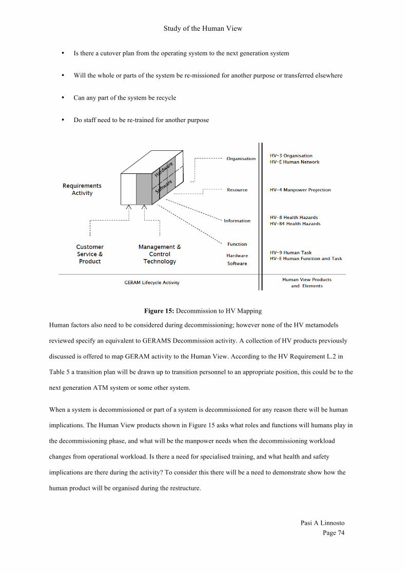
Study of the Human View
Pasi A Linnosto Page 74
• Is there a cutover plan from the operating system to the next generation system
• Will the whole or parts of the system be re-missioned for another purpose or transferred elsewhere
• Can any part of the system be recycle
• Do staff need to be re-trained for another purpose
Figure 15: Decommission to HV Mapping
Human factors also need to be considered during decommissioning; however none of the HV metamodels
reviewed specify an equivalent to GERAMS Decommission activity. A collection of HV products previously
discussed is offered to map GERAM activity to the Human View. According to the HV Requirement L.2 in
Table 5 a transition plan will be drawn up to transition personnel to an appropriate position, this could be to the
next generation ATM system or some other system.
When a system is decommissioned or part of a system is decommissioned for any reason there will be human
implications. The Human View products shown in Figure 15 asks what roles and functions will humans play in
the decommissioning phase, and what will be the manpower needs when the decommissioning workload
changes from operational workload. Is there a need for specialised training, and what health and safety
implications are there during the activity? To consider this there will be a need to demonstrate show how the
human product will be organised during the restructure.

Study of the Human View
Pasi A Linnosto Page 75
6. CONCLUSION The study into the Human View and its evolution has given Human Factor Integrators a better understanding the
nature of a human element as it is integrating into a system.
The reason why we considering humans as part of the system development in an enterprise is because; their
skills and abilities can be assessed as part of the system and the interface between the technological components.
Over the life cycle of any system the human element is considered the most costly resource, so efficient use of
resources within a system can reduce cost across the enterprise lifecycle (Defense, 18 May 2009; H. Handley &
Smillie, 2010). By considering the human resource across an Enterprise lifecycle, costs associated with the
system can be controlled.
By comparing the Human Views to the GERAM lifecycle this research has shown that there are areas within the
current HV study that can be enhanced without abandoning existing work.
It remains unclear from this study why the fundamental the human view products founded in the NATO
Metamodel were changed for the Canadian Human View. The products and elements in both metamodels seem
to be defined in much the same way when they were present in both instances. It is also unclear why NATO HV
refers to (HV-A to HV-H) as products and the Canadian HV refer to (HV-1 to HV-10) as elements. However
because this paper’s primary interest is mapping the terminology and the previously mapped components was
retained unless otherwise stated.
In order to map NATO elements to GERAM this paper chose to take a different approach to the method
developed in the Canadian Approach. By splitting HV-B5 Health Hazards and HV-7 System Safety into
Requirements and Preliminary Design activities of GERAM Lifecycle, Health Hazards could be defined as a
requirement against a specific standard, whilst System Safety could be applied by individuals during their day-
to-day activity.
Missing from the Canadian Human View Reference Chart were some of the NATO HV elements. I was able to
include HV-H Human Dynamics into the Build activity of GERAM Lifecycle where Human Dynamic networks
would be most evident. I was also able to map HV-B2 Career Projection and HV-G Metrics into the Operation
activity of GERAM Lifecycle where they could be used to define the Human element during a systems
operation.

Study of the Human View
Pasi A Linnosto Page 76
By mapping the two metamodels to GERAM lifecycle I was able to theoretical define all the Canadian HV
elements and all but one of the NATO HV products (HV-B6 Personnel Policy). The reason for not mapping the
HV-B4 Personnel Policy element was because of differing legal descriptions between federal, state and local
laws.
By taking one step further and mapping HV to the GERAM lifecycle I have shown how the generalised
framework is better able to identify gaps in the current study than previously studied defence architectural
frameworks.
Further work may be performed to improve the HV framework (essentially a metamodel of human-related
concepts) of defence AFs by assessing whether these metamodels are appropriate for every typical life history
stage of a system of interest. E.g. when the system of interest is in an initial feasibility study stage, the models
(‘architecture products’) describing the HV are likely to be different from the HV models that are of importance
in the support stage. This is because the stakeholder concerns regarding the system of interest are likely to
change, thus requiring new, or changed, architecture descriptions. Even if the metamodel included all necessary
concepts (covering the entire life history of a system), the question still remains, which HV products are useful /
necessary in each respective stage of a system’s life. However, the present thesis has not investigated answers
to this question.
By mapping HV elements to GERAM framework we have identified areas in the Human View study that do not
map completely to the GERAM lifecycle. By making modest improvements to the presentation of data during
requirements and design activities value is added to the HV study.
By examining GERAM Lifecycle Identification activity we can see that none of the defence oriented the Human
View metamodels consider entering the lifecycle before beginning to development concepts and other
developmental activities. I may theorise that this could be due to the inherent nature of working in a military
environment. Projects of interest are identified by defence acquisition office prior to selecting a suitable
government entity or contractor to complete the work. Defence contractors would find benefits in applying
Enterprise Architecture to the Human Views as part of the decision-making process to ‘go’ or ‘not go’ ahead
with the project in its current form. Equally defence acquisition office’s may benefit from the inclusion of an
Enterprise Architect Human View study as part of the decision making process.
Study of the Human View
Pasi A Linnosto Page 77
Gaps identified in the Concept activity study could be expanded upon to include satisfy mission vision, values
and strategy along with the appropriate level of clarity in Policy, Process and Business Plan. Although the
statements and plans may exist in an organisation it is not satisfactory to assume that the statements and plans
are axiomatic to the system being considered. Benefits may be drawn from the inclusion of an Enterprise
Architect Human View study as part of concept development.
Gaps identified in the Operate activity study could be expanded upon to identify career progression in the
GERAM lifecycle activity. The current Canadian HV study does not include career progression that was present
in the original NATO HV study as HV-B2 (H. Handley & Smillie, 2008). In this study we found that HV-B2
did not adequately satisfy a Human trait for self-satisfying career betterment by becoming better at ones current
job or post.
GERAM is one of many Architectural standard that could have been used to map the Human Views, future
studies may choose to utilise another Architectural framework such as TOGAF or the Zachman Framework, or
even a combination of Enterprise Architectural to further understand the strengths and limitations of the Human
View field.
Note: The next new research underway is to map the Canadian HV and Zachman. The research may add
additional value to the study in the Human View that was not evident at the commencement to this study.
This study was conceptual analytical research that led to a Tabula Rasa view of the subject. Future direction
could be to expand the field with empirical research that would involve gathering data from system matter
experts developing an enterprise, identifying relevant human information about the system and derive wisdom
from the information to develop HV meta-models relevant to an architectural standard.
Direction this empirical research could take would be to compare the organisational structure of the military unit
working within the normal organisational constraints of the armed forces and comparing this to an autonomous
group such as a Special Military Forces group who operate autonomously within the armed forces.

Study of the Human View
Pasi A Linnosto Page 78
Table 11: List of Acronyms
ACCE Air Component Coordination Element ADATS
Australian Defence Air Traffic System
AoF
Allocation of Function ASA
Air Services Australia
ATM Air Traffic Management ATO
Air Tasking Order
BMS
Bionic Manufacturing System C2
Command and Control
CAOC Combined Aerospace Operations Centre CASA
Civil Aviation Safety Authority
CDM
Conceptual Data Model CFAWAC
Canadian Forces Aerospace Warfare Centre
DNDAF Department of National Defence and the Canadian Forces Architecture Framework DODAF
Department of Defence Architectural framework
EA Enterprise Architecture EMP
Engineering Management Plan
FELP Force Element Lead Planner FF
Fractal Factory
FINC
Force Intelligence, Networking and C2 GERAM The Generalised Enterprise Reference Architecture and Methodology HFI Human Factor Integration HFM Human Factors and Medicine HIS Human System Integration HIS HVDA Human Systems Integration Human View Dynamic Architect HMS
Holonic Manufacturing System
HV Human View INCOSE
International Council on Systems Engineering
JAOP Joint Air Operations Plan JTFC Joint Task Force Command LDM
Logical Data Model
MAAP
Master Aerospace Action Plan MFTA Mission, Function, Task Analysis MHQwMOC Maritime Headquarters with Maritime Operations Centre MoDAF Ministry of Defence Architecture Framework NATO North Atlantic Treaty Organization NORAD North American Aerospace Defence Command OODA
Orient observe decide act
PES
Physical Exchange Specification RAAF
Royal Australian Air Force
RAPCON
Radar Approach Control RNLN Royal Netherlands Navy RTO Research and Technology Organisation SAR Search and Rescue
Study of the Human View
Pasi A Linnosto Page 79
SE System Engineering SME
System Matter Expert
SS
System Specification TAD
Target Audience Description
TAMM
Technical Airworthiness Management Manual TARM Total Air Resource Management TOGAF
The Open Group Architecture Framework
TSS
Top Level System Specification USAF
United States Air Force
V-CAOC Virtual Combined Aerospace Operations Centre YFR Yearly Flying Rate

Study of the Human View
Pasi A Linnosto Page 80
Bibliography Baker, K., & Youngson, G. (2007). Advanced Integrated Multi-sensor Surveillance (AIMS). Mission,
Function, Task Analysis: DTIC Document. Bernus, P., Nemes, L., & Schmidt, G. (2003). Handbook on Enterprise Architecture.
Berlin,Heidelberg,NY: Springer Verlag. Bernus, P., & Noran, O. (2010). A Metamodel for Enterprise Architecture Enterprise Architecture,
Integration and Interoperability (pp. 56-65): Springer. Bruseberg, A. (2010). The Human View Handbook for MODAF. (2). Coats C, S. A., Wang W. (2013). Canadian Human View Handbook. Defence, A. G. D. o. (2013). AIR5431, from http://www.defence.gov.au/dmo/id/dcp/html/air/AIR5431.html Defense, D. o. (18 May 2009). Department of Defense Architecture Framework. [Manager's Guide].
(Version 2.0). Dekker, A. (2002). C4ISR architectures, social network analysis and the FINC methodology: an
experiment in military organisational structure: DTIC Document. FAWG. (Feb 2001). Federal Enterprise Architecture. (1.0). Framework, D. o. N. D. a. t. C. F. A. (2011). DND Architectural Framework Version 1.8. Haimes, Y. Y., Kaplan, S., & Lambert, J. H. (2002). Risk filtering, ranking, and management framework
using hierarchical holographic modeling. Risk Analysis, 22(2), 383-397. Handley, H., & Smillie, R. (2008). Architecture framework human view: The NATO approach. Systems
Engineering, 11(2), 156-164. Handley, H., & Smillie, R. (2010). Human view dynamics - The NATO approach. Systems Engineering,
13(1), 72-79. Handley, H. A. (2012). Incorporating the NATO Human View in the DoDAF 2.0 Meta Model. Systems
Engineering, 15(1), 108-117. Järvinen, P. (2004). On research methods. (3rd). Kotter, J. P. (1996). Leading change: Harvard Business Press. Luftman, J. (2003). Assessing IT/business alignment. Information Strategy, 20(1), 7-7. Lundin, S., Nelson B. (2010). Ubuntu. [Book]. 132. Mathews, J. (1996). Holonic organisational architectures. Human Systems Management, 15(1), 27. McConnell, S. (2009). Software Estimation: Demystifying the Black Art: Demystifying the Black Art:
Microsoft press. MoD, U. (2008). Ministry of defence architecture framework: Versions. Platje, A., & Wadman, S. (1998). From Plan-Do-Check-Action to PIDCAM: the further evolution of the
Deming-wheel. International Journal of Project Management, 16(4), 201-208. Risk Decisions Management soulutions. from http://www.riskdecisions.com Sheard, S. A. (1996). Twelve systems engineering roles. Paper presented at the Proceedings of INCOSE. Sridhar, N. (2011). Risk Assessment of Corrodible Systems-An Overview. Materials Performance, 50(6),
32-38. Stewart, A., Baker, K., Pogue, C., & Ramotar, R. (2008). Human Views: Extensions to the Department of
Defense Architecture Framework: CAE PROFESSIONAL SERVICES OTTAWA (ONTARIO). Tharumarajah, A., Wells, A., & Nemes, L. (1998). Comparison of emerging manufacturing concepts. Paper
presented at the Systems, Man, and Cybernetics, 1998. 1998 IEEE International Conference on. Wenbu, W., & Curtis, C. (2013). Human View Modelling of the Virtual - Combined Areospace
Operations Centre (V-CAOC) Draft. [Technical Report]. Defence R&D Canada - Toronto.