2016/06 AO-SM-60-20 REV 2.0
For Parts or Technical Assistance:
USA: 1-800-327-0770
Operation/Maintenance Manual
Stryker Air™
Pump 2861
2016/06 AO-SM-60-20 REV 2.0 Page 2 of 24
Table of Contents
Page
Symbols and Definitions
Symbols ………………………………………...…………………………………………………………………. 3
Warning / Caution Definitions ….………...……………………………………………………………………… 4
Introduction
Intended Use of the Product ...…………………………………………………………………………………. 5
Product Description …………….………………………………………………………………………………… 5
Operating Principle ……………………………………………………………………………………………….. 5
Specifications …………….……………………………………………………………………………………….. 6
Contact Information …………….………………………………………………………………………………… 7
Product Serial Number Location/Format…………….………………………………………………………..... 7
Summary of Safety Precautions …………….…………………………………………………………………. 8-9
Pump Assembly …………………………………………………………………………………………….…….. 10
Pump Operation
Control Panel ……………………………………………………………………………………………………... 11
Key Functions …………………………………………………………………………………………………….. 11
Alarm Function …………………………………………………………………………………………………… 11
Procedure:
Installation/Operation of the Stryker AirTM
Pump with the SPRPlusTM
Support Surface …….….…………. 12
Installation/Operation of the Stryker AirTM
Pump with the IsoFlexLALTM
Support Surface……….…….... 13
Troubleshooting
Troubleshooting Guide.………………………………………..…………………………….…………………… 14
Alarm Priority Table ………….……………………………………………………………………………….….. 14
Cleaning and Disinfection ………………………………………………………………………………...…….. 15
Service Information
Circuit Breaker Reset …………….………………………………………………………….…………………… 16
Hose Assembly Replacement ………………………………………………………………………………...... 16
Preventive Maintenance
Checklist and Maintenance Record …………………………………..……………………………………....... 17
Quick Reference Replacement Parts List …………………………………………………………………….. 18
Product Compliance Declarations
Guidance and Manufacturer’s Declaration – Electromagnetic Emissions………………...………………... 19
Guidance and Manufacturer’s Declaration – Electromagnetic Immunity …………………………………... 19
Guidance and Manufacturer’s Declaration – Electromagnetic Immunity – Non Life Supporting …….….. 20
Guidance and Manufacturer’s Declaration – Recommended Separation Distances …………..……..…. 21
Warranty
Limited Warranty …………………………………………………………………………………………………. 22
Conditions and Limitations ………………………………………………………………………………………. 22
To Obtain Parts and Service ………………………………………………………………………………......... 22
Return Authorization …………………………………………………………………………………………....... 22
Damaged Merchandise ………………………………………………………………………………………….. 22
2016/06 AO-SM-60-20 REV 2.0 Page 3 of 24
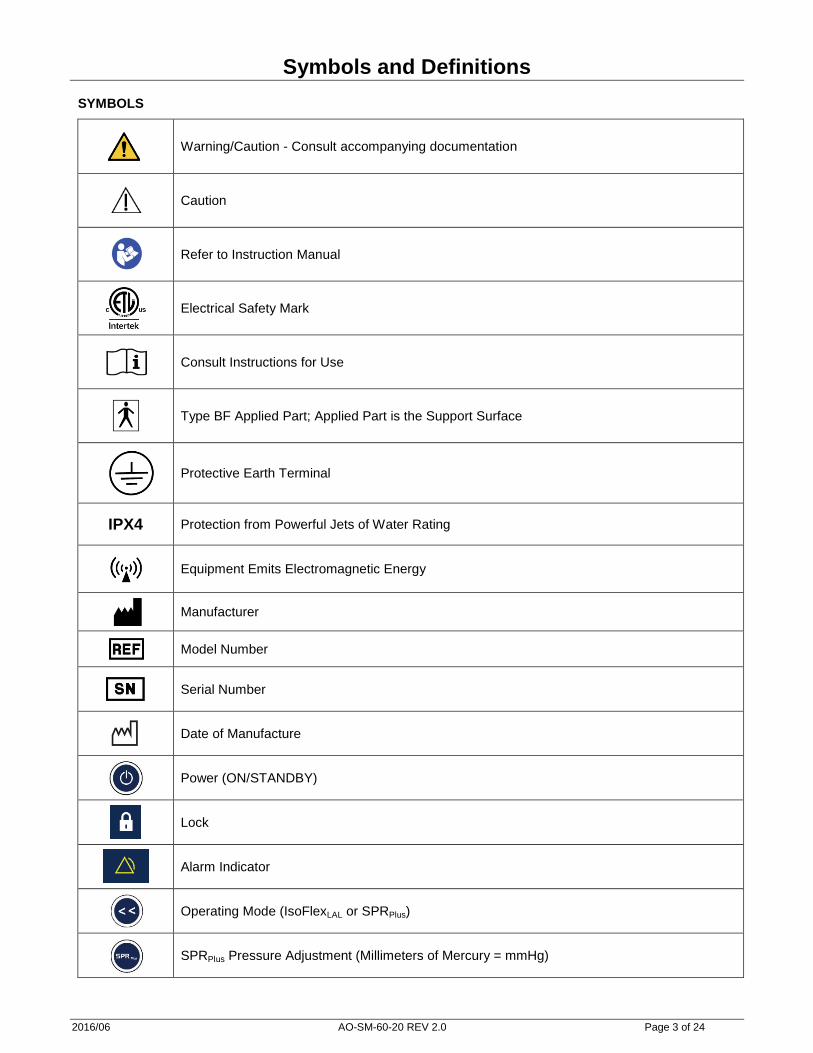
Symbols and Definitions SYMBOLS
Warning/Caution - Consult accompanying documentation
Caution
Refer to Instruction Manual
Electrical Safety Mark
Consult Instructions for Use
Type BF Applied Part; Applied Part is the Support Surface
Protective Earth Terminal
IPX4 Protection from Powerful Jets of Water Rating
Equipment Emits Electromagnetic Energy
Manufacturer
Model Number
Serial Number
Date of Manufacture
Power (ON/STANDBY)
Lock
Alarm Indicator
Operating Mode (IsoFlexLAL or SPRPlus)
SPRPlus Pressure Adjustment (Millimeters of Mercury = mmHg)

2016/06 AO-SM-60-20 REV 2.0 Page 4 of 24
Symbols and Definitions
WARNING / CAUTION
The words WARNING and CAUTION carry special meanings and should be carefully reviewed.
WARNING Alerts the reader about a situation which, if not avoided, could result in death or serious injury. It may also
describe potential serious adverse reactions and safety hazards.
CAUTION Alerts the reader of a potentially hazardous situation which, if not avoided, may result in minor or moderate
injury to the user or patient or damage to the equipment or other property. This includes special care necessary
for the safe and effective use of the device and the care necessary to avoid damage to a device that may occur
as a result of use or misuse.

2016/06 AO-SM-60-20 REV 2.0 Page 5 of 24
Introduction
This manual is designed to assist with the operation and maintenance of the Stryker AirTM
Pump (“Pump”) that
is used to power both the Stryker SPRPlusTM
Single Patient Use Low Air Loss Overlay System (“SPRPlus”) and
IsoFlexLALTM
Support Surface. The SPRPlus is only for use in the United States.
Carefully read this entire manual before using or beginning maintenance on the Pump. To ensure safe
operation of this equipment, it is recommended that methods and procedures are established for educating and
training staff on the safe operation of the Pump.
INTENDED USE OF THE PRODUCT
The Pump is an accessory used with the SPRPlus and IsoFlexLAL Support Surface to assist in the prevention and
treatment of pressure ulcers. This therapy is recommended to be used in combination with clinical evaluation of
risk factors and skin assessments made by a health care professional. Patients may be excluded due to some
medical conditions such as unstabilized spinal cord injuries or other conditions as determined by the facilities
professional staff.
This Pump is intended to be used:
− With the Stryker SPRPlus or IsoFlexLAL Support Surface only.
− With the hosing and connector assembly provided (Part Number 2861-001-001).
− In acute care, general hospital care, or other locations as prescribed by a physician.
This product is not intended to be used in a home health care environment.
PRODUCT DESCRIPTION
The Pump provides Low Air Loss Therapy and when used in conjunction with SPRPlus or IsoFlexLAL Support
Surface assists in the prevention and treatment of pressure ulcers and includes the following features:
- The Pump is a versatile accessory that may be used with either the SPRPlus or the IsoFlexLAL Support
Surface.
- Easily attaches to the Footboard of the Bed Frame.
- Incorporates an alarm for detection of hose disconnection from the Pump.
- Designed with a “User-Friendly” Control Panel.
OPERATING PRINCIPLE
The Stryker Air Pump is designed to work with either the IsoFlexLAL (Low Air Loss) mattress or the SPRPlus
mattress overlay. When used with the IsoFlexLAL mattress, the Pump provides a continuous flow of air to the
mattress for the Low Air Loss feature of the mattress. Air flows inside the mattress to the underside of the cover
to remove moisture. The mattress, by itself, provides all the necessary support for the patient. The Pump does
not provide support of the patient.
When the Pump is used with the SPRPlus mattress overlay, the Pump provides air for patient support and Low Air
Loss. The patient is supported by air pressure in the mattress overlay. The Pump adjusts its air output to obtain
the pressure value selected by the user. Small pin holes in the top side of the mattress overlay “leak” air to
achieve the Low Air Loss therapy.

2016/06 AO-SM-60-20 REV 2.0 Page 6 of 24
Introduction
SPECIFICATIONS
Pump
Dimensions Height: 8.5 in / 21.6 cm Width: 8 in / 20.3 cm Depth: 5 in/ 12.7 cm
Weight 6 lbs/ 2.7kgs
Input Voltage AC 110 - 127 Volts
Input Frequency 50 - 60 Hz
Current Consumption 0.25 Amps
Power Consumption < 60 VA
Circuit Protection Dual Circuit Breakers, 240V, 1.0A
Mode of Operation Continuous
Protection Against Electrical Shock Class I, Type BF Applied Part
Air Output − 12.5 Liters / Minute @ 30 mmHg
− 25 Liters / Minute @ 20 mmHg
Pressure Settings (mmHg) 18 to 30 mmHg in 3 mmHg Increments
Power Cord 3 ft/ 0.91m (For Bed Frame Outlet) 15 ft / 4.6m; (For Wall Outlet)
Air Hose 56 in / 142 cm
Air Hose Connection 3/8 Inch Flow Quick Coupling
Packaging 1 Piece per Box
Latex Content User accessible parts of the Pump are not made with natural rubber latex.
Alarms (See Page 14):
Sound Pressure Level 63.1 dB(A)
Hose Disconnection Alarm (Low Priority Alarm)
− Indicated after 15 minutes for hose disconnection from Pump
(SPRPlus Mode)
Hose Disconnection / High Pressure Alarm (Medium Priority Alarm)
− Indicated after 30 minutes for hose disconnection from Pump
(SPRPlus Mode)
− Indicated after 30 seconds for excessive Pump pressure
System Alarm (Medium Priority Alarm)
− If system error is detected
− Stuck Button
Operating Conditions:
Ambient Temperature 40 to 90 o
F / 5 to 32 o
C
Relative Humidity 30 to 75 % Non-Condensing
Atmospheric Pressure 700 to 1060 hPa
Storage and Shipping Conditions:
Ambient Temperature -40 to158 oF / -40 to 70
oC
Relative Humidity 10 to 95 %, Non-Condensing
Atmospheric Pressure 500 to 1060 hPa
Protection Against Harmful Ingress of Liquids:
Liquid Ingress Protection IPX4
Product Compliance:
Medical Equipment IEC 60601-1 (3
rd Edition)
UL 60601-1 CAN/CSA C22.2 No. 60601-1-08
Collateral Standards Electromagnetic Compatibility IEC 60601-1-2 (See Pages 19-21)
Usability IEC 60601-1-6
Stryker reserves the right to change specifications without notice.

2016/06 AO-SM-60-20 REV 2.0 Page 7 of 24
Introduction
CONTACT INFORMATION
Contact Stryker Customer Service or Technical Support at: (800) 327-0770 or (269) 324-6500.
Stryker Medical
3800 E. Centre Avenue
Portage, MI 49002
USA
Please have the serial number of your Stryker product available when calling Stryker Customer Service or
Technical Support. Include the serial number in all written communication.
SERIAL NUMBER LOCATION
The serial number is located on the back of the Pump, on the rear label.
SERIAL NUMBER FORMAT (8 DIGITS):
Serial Number Example: 15J00234
1 5 J 0 0 2 3 4
Manufacture Date (YY/M): 2015 September Sequential Number (NNNNN): 00234
Month Legend (M)
January A
February B
March C
April D
May E
June F
July G
August H
September J
October K
November L
December M
Year Legend (YY)
2015 15
2016 16
2017 17
2018 18
2019 19
Sequential # Legend (NNNNN)
00001 - 99999
Y M N N Y N N N

2016/06 AO-SM-60-20 REV 2.0 Page 8 of 24
Summary of Safety Precautions
Carefully read and strictly follow the warnings and cautions listed in this section.
WARNING
− Before operating this medical equipment:
Read this manual to understand the operating instructions and safety precautions. Failure to do
this could result in patient injury and/or damage to the product.
To avoid the risk of electric shock inspect Pump and power cord for damage. If damage is
observed, take the Air Supply Unit out of operation immediately and contact Customer Service.
(See Page 7 for Contact Information).
Pump is only to be used with the SPRPlus or IsoFlexLAL Support Surface mattresses. Read the
User’s Manual for the SPRPlus or IsoFlexLAL Support Surface before using it with the Pump.
Entrapment and Falls: Consult the instructions for use of the compatible support surface and
overlay for additional cautions and warnings. Failure to do so could result in injury or death.
− Do not modify or change this device. Service should only be completed by qualified personnel. Failure
to do so could result in injury and void warranty.
− This equipment radiates radio frequency energy and, if not installed and used in accordance with the
instructions, may cause harmful interference to other devices in the vicinity (See Pages 19-21).
However, there is no guarantee that interference will not occur in a particular installation. If this
equipment does cause harmful interference to other devices, which can be determined by turning the
equipment off and on, the user is encouraged to try to correct the interference by one or more of the
following measures:
Reorient or relocate the receiving device.
Increase the separation between the Pump and other equipment.
Connect the equipment into an outlet on a circuit different from that to which other device(s) are
connected.
Consult with Stryker Technical Support for assistance.
− Grounding reliability can only be achieved when the Pump is connected to Hospital Grade receptacle.
Failure to provide proper grounding could result in a risk of electric shock.
− Do not use multiple socket outlets or extensions.
− Improper use, or handling, of the power cord could result in damage. If damage has occurred to the
power cord, remove from use and call qualified maintenance personnel for replacement (See Page 7).
− Only use approved Hospital Grade power cords. Use of unapproved power cords could result in a risk of
fire or electric shock.
− Do not use in the presence of flammable anesthetics, nitrous oxide, or in oxygen-rich environments. Risk
of explosion can result.
− Exposure of the Pump to any liquid while it is plugged in could result in a severe electrical hazard.
− Risk of Electric Shock. Do not open or attempt to repair or service the electronic Pump. Repairs and
service should only be done by authorized personnel. If the Pump is not functioning properly, or has been
damaged, unplug the unit and take it out of service immediately and contact Technical Support. See
Page 7 for contact information.
− There are no batteries in the unit, if power fails the product will not work nor continue air flow.
− If the SPRPlus is not inflating properly, inspect the hose connection to overlay to ensure connection is
seated properly.
− To avoid damage to the Pump or potential injury, only trained personnel should open the Pump.
− When hanging the controller on the foot board, ensure the hangers are seated as the hangers are not
spring loaded and may come dislodged if not properly hung.

2016/06 AO-SM-60-20 REV 2.0 Page 9 of 24
Summary of Safety Precautions (continued)
− Do not spray disinfectant directly on the electrical Pump, or immerse the Pump in any type of liquid. This
could result in a severe electrical hazard.
− Initiate deflation of the SPRPlus Overlay before starting CPR. Failure to do so may result in ineffective
CPR.
− SPRPlus is a mattress overlay and should not be used as a mattress replacement. Failure to use the
SPRPlus on a mattress may result in damage to the overlay or injury to the patient. Refer to SPRPlus
Support Surface User’s Manual.
CAUTION
− The Pump is a precision electronic product. Use care when handling or transporting. Dropping, or other
sudden impacts, may result in damage to the Pump.
− After exposure to extreme high or low temperatures, allow the Pump to equilibrate for at least one (1)
hour before operating.
− The Pump circulates room air during operation. Exposure to smoke may cause the Pump to fail.
Therefore, smoking by patients, or visitors, while using this product is contraindicated.
− The power cord to the Pump should be positioned to avoid a tripping hazard and/or damage to the cord.
Stryker recommends placing the cord under the bed frame and plugging it into an electrical outlet by the
head end of the bed.
− Before plugging in the Pump, check the power cord for electrical hazards, e.g., cuts, exposed wires, worn
insulation, etc. If hazards are present, remove from use immediately and contact Customer Service (See
Page 7 for Contact Information).
− To ensure optimal performance electrical-safety testing of your Pump should be performed at least
annually. Contact Technical Support, Page 7, for service information.
− Disinfect the Pump and Hosing Assembly between patient installations and when servicing, utilizing
standard hospital protocol and disinfectants. Failure to disinfect may risk cross-contamination and
infection.
− Do not return a Pump for any reason without first contacting Customer Service to obtain authorization.
− Consult your local regulations to properly dispose of electronic equipment

2016/06 AO-SM-60-20 REV 2.0 Page 10 of 24
Pump Assembly
The location of features and connections on the Pump are presented below. Please refer to these during
installation, set up and operation of the Pump.
FRONT VIEW –
Sound Dampening
Bumpers
Control Panel
Adjustable Pump
Hangers
Air Hose Outlet
Air Hose Outlet Power Cord Inlet
Protective Ground
Test Point
Circuit Breakers
Hanger
Adjustment
Pins
BACK VIEW -
2016/06 AO-SM-60-20 REV 2.0 Page 11 of 24
Pump Operation
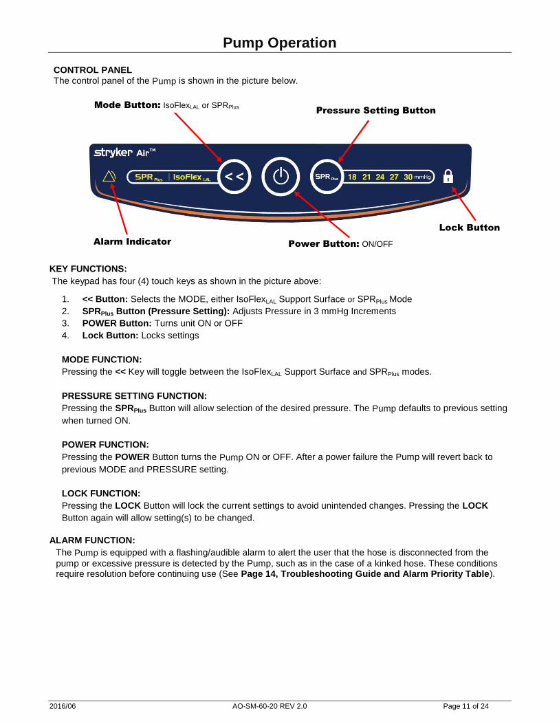
CONTROL PANEL The control panel of the Pump is shown in the picture below.
KEY FUNCTIONS:
The keypad has four (4) touch keys as shown in the picture above:
1. << Button: Selects the MODE, either IsoFlexLAL Support Surface or SPRPlus Mode
2. SPRPlus Button (Pressure Setting): Adjusts Pressure in 3 mmHg Increments
3. POWER Button: Turns unit ON or OFF
4. Lock Button: Locks settings
MODE FUNCTION:
Pressing the << Key will toggle between the IsoFlexLAL Support Surface and SPRPlus modes.
PRESSURE SETTING FUNCTION:
Pressing the SPRPlus Button will allow selection of the desired pressure. The Pump defaults to previous setting
when turned ON.
POWER FUNCTION:
Pressing the POWER Button turns the Pump ON or OFF. After a power failure the Pump will revert back to
previous MODE and PRESSURE setting.
LOCK FUNCTION:
Pressing the LOCK Button will lock the current settings to avoid unintended changes. Pressing the LOCK
Button again will allow setting(s) to be changed.
ALARM FUNCTION:
The Pump is equipped with a flashing/audible alarm to alert the user that the hose is disconnected from the
pump or excessive pressure is detected by the Pump, such as in the case of a kinked hose. These conditions require resolution before continuing use (See Page 14, Troubleshooting Guide and Alarm Priority Table).
Power Button: ON/OFF Alarm Indicator
Pressure Setting Button
Lock Button
Mode Button: IsoFlexLAL or SPRPlus

2016/06 AO-SM-60-20 REV 2.0 Page 12 of 24
Pump Operation
PROCEDURE
Installation and Operation of the Stryker Air Pump for Use With the SPRPlus Support Surface
Step Installation Procedure Cautions and Warnings
1 Refer to the SPRPlus User’s Manual for installation of the Support Surface. WARNING
− Consult the user’s manual for the SPRPlus Support Surface before attaching it to the Pump. Failure to do so could result in patient injury and/or improper therapy.
− Grounding reliability can only be achieved when the Pump is connected to a Hospital Grade Receptacle. Failure to provide proper grounding could result in a risk of electric shock.
− Do not use in the presence of flammable anesthetics, nitrous oxide, or oxygen-rich environments. Risk of explosion can result.
− Exposure of the electronic Pump to any liquid while it is plugged in could result in a severe electrical hazard.
− The Pump radiates radio
frequency energy and, if not installed and used in accordance with the instructions, may cause harmful interference to other devices in the vicinity.
− If “Button-Click” sound is not heard during Step 1 of the Operation Procedure, remove from use.
− Only use SPRPlus Overlay on a mattress.
CAUTION
− After exposure to extreme high or low temperatures, allow the Pump to equilibrate for at least one (1) hour before operating.
− Before plugging in the Pump,
check the power cord for
electrical hazards, e.g., cuts,
exposed wires, worn
insulation, etc.
2 Installing the Pump:
1) Hang the unit on the foot panel of the bed. 2) The Pump is equipped with a detachable power cord. To apply power, the cord
must be attached to the Pump and the electrical outlet on the wall. To disconnect power, the cord may be detached from either the Pump or the wall outlet.
3) Stretch the power cord beneath the bed to an outlet at the head end of the bed, making sure the cord is out of the way.
4) If you are installing the Support Surface on a Stryker bed frame, use the optional power outlet located under the foot end of the frame and the short power cord provided. Ensure the outlet is a Hospital Grade receptacle.
3 Screw the Red Hose Connector Cap tightly onto the Support Surface connector as
shown below. Use caution so as not to cross the threads of the connector.
4 Attach other end of hose to the Pump using the Quick-Disconnect connector.
Step Operation Procedure
1 While standing in front of the Pump, press the POWER Button located on the Control
Panel to turn the Pump ON. Listen for a “Button-Click” sound to verify operation of audio-
alarm system. If controller lights do not come on, see Troubleshooting Page 14.
2 Select the SPRPlus mode using the << key The“SPRPlus” will then be illuminated. The
Pump will start inflating the cushion. The cushion will inflate in approximately 10 minutes.
Start with the pressure set to 18mmHg.
3 The SPRPlus Pump is capable of adjusting the cushion pressure to five set points over a
range of 18 to 30 mmHg. The five set points can be adjusted directly by the SPRPlus
Button. The settings will return to the last used setting if the unit experiences a loss of
power.
4 The only way to assure that the patient is getting the proper therapy is with periodic
HAND CHECKS to establish the correct pressure setting. Please refer to the SPRPlus
User’s Manual for how to perform the HAND CHECK.
Step CPR
1 Refer to the SPRPlus User’s Manual for CPR procedure.
2 Disconnect hose from the Pump using the Quick-Disconnect connector.
2016/06 AO-SM-60-20 REV 2.0 Page 13 of 24
Pump Operation
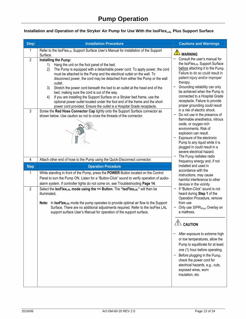
Installation and Operation of the Stryker Air Pump for Use With the IsoFlexLAL Plus Support Surface
Step Installation Procedure Cautions and Warnings
1 Refer to the IsoFlexLAL Support Surface User’s Manual for installation of the Support Surface. WARNING
− Consult the user’s manual for the IsoFlexLAL Support Surface before attaching it to the Pump. Failure to do so could result in patient injury and/or improper therapy.
− Grounding reliability can only be achieved when the Pump is connected to a Hospital Grade receptacle. Failure to provide proper grounding could result in a risk of electric shock.
− Do not use in the presence of flammable anesthetics, nitrous oxide, or oxygen-rich environments. Risk of explosion can result.
− Exposure of the electronic Pump to any liquid while it is plugged in could result in a severe electrical hazard.
− The Pump radiates radio
frequency energy and, if not installed and used in accordance with the instructions, may cause harmful interference to other devices in the vicinity.
− If “Button-Click” sound is not heard during Step 1 of the Operation Procedure, remove from use
− Only use SPRPlus Overlay on a mattress.
CAUTION − After exposure to extreme high
or low temperatures, allow the
Pump to equilibrate for at least
one (1) hour before operating.
− Before plugging in the Pump,
check the power cord for
electrical hazards, e.g., cuts,
exposed wires, worn
insulation, etc.
2 Installing the Pump:
1) Hang the unit on the foot panel of the bed. 2) The Pump is equipped with a detachable power cord. To apply power, the cord
must be attached to the Pump and the electrical outlet on the wall. To disconnect power, the cord may be detached from either the Pump or the wall outlet.
3) Stretch the power cord beneath the bed to an outlet at the head end of the bed, making sure the cord is out of the way.
4) If you are installing the Support Surface on a Stryker bed frame, use the optional power outlet located under the foot end of the frame and the short power cord provided. Ensure the outlet is a Hospital Grade receptacle.
3 Screw the Red Hose Connector Cap tightly onto the Support Surface connector as shown below. Use caution so not to cross the threads of the connector.
4 Attach other end of hose to the Pump using the Quick-Disconnect connector.
Step Operation Procedure
1 While standing in front of the Pump, press the POWER Button located on the Control
Panel to turn the Pump ON. Listen for a “Button-Click” sound to verify operation of audio-
alarm system. If controller lights do not come on, see Troubleshooting Page 14.
2 Select the IsoFlexLAL mode using the << Button. The “IsoFlexLAL“ will then be illuminated. Note: In IsoFlexLAL mode the pump operates to provide optimal air flow to the Support
Surface. There are no additional adjustments required. Refer to the IsoFlex LAL support surface User’s Manual for operation of the support surface.
2016/06 AO-SM-60-20 REV 2.0 Page 14 of 24
Troubleshooting
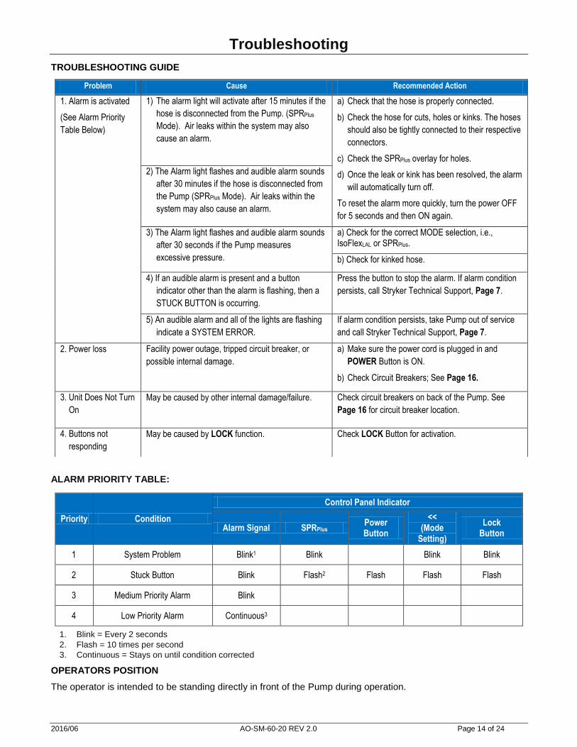
TROUBLESHOOTING GUIDE
ALARM PRIORITY TABLE:
Priority Condition
Control Panel Indicator
Alarm Signal SPRPlus Power Button
<< (Mode
Setting)
Lock Button
1 System Problem Blink1 Blink Blink Blink
2 Stuck Button Blink Flash2 Flash Flash Flash
3 Medium Priority Alarm Blink
4 Low Priority Alarm Continuous3
1. Blink = Every 2 seconds 2. Flash = 10 times per second 3. Continuous = Stays on until condition corrected
OPERATORS POSITION
The operator is intended to be standing directly in front of the Pump during operation.
Problem Cause Recommended Action
1. Alarm is activated
(See Alarm Priority
Table Below)
1) The alarm light will activate after 15 minutes if the
hose is disconnected from the Pump. (SPRPlus
Mode). Air leaks within the system may also
cause an alarm.
a) Check that the hose is properly connected.
b) Check the hose for cuts, holes or kinks. The hoses
should also be tightly connected to their respective
connectors.
c) Check the SPRPlus overlay for holes.
d) Once the leak or kink has been resolved, the alarm
will automatically turn off.
To reset the alarm more quickly, turn the power OFF
for 5 seconds and then ON again.
2) The Alarm light flashes and audible alarm sounds
after 30 minutes if the hose is disconnected from
the Pump (SPRPlus Mode). Air leaks within the
system may also cause an alarm.
3) The Alarm light flashes and audible alarm sounds
after 30 seconds if the Pump measures
excessive pressure.
a) Check for the correct MODE selection, i.e., IsoFlexLAL or SPRPlus.
b) Check for kinked hose.
4) If an audible alarm is present and a button
indicator other than the alarm is flashing, then a
STUCK BUTTON is occurring.
Press the button to stop the alarm. If alarm condition
persists, call Stryker Technical Support, Page 7.
5) An audible alarm and all of the lights are flashing
indicate a SYSTEM ERROR.
If alarm condition persists, take Pump out of service
and call Stryker Technical Support, Page 7.
2. Power loss Facility power outage, tripped circuit breaker, or
possible internal damage.
a) Make sure the power cord is plugged in and
POWER Button is ON.
b) Check Circuit Breakers; See Page 16.
3. Unit Does Not Turn
On
May be caused by other internal damage/failure. Check circuit breakers on back of the Pump. See
Page 16 for circuit breaker location.
4. Buttons not
responding
May be caused by LOCK function. Check LOCK Button for activation.
2016/06 AO-SM-60-20 REV 2.0 Page 15 of 24
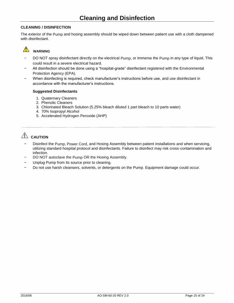
Cleaning and Disinfection CLEANING / DISINFECTION
The exterior of the Pump and hosing assembly should be wiped down between patient use with a cloth dampened
with disinfectant.
WARNING
− DO NOT spray disinfectant directly on the electrical Pump, or immerse the Pump in any type of liquid. This
could result in a severe electrical hazard.
− All disinfection should be done using a “hospital-grade” disinfectant registered with the Environmental
Protection Agency (EPA).
− When disinfecting is required, check manufacturer’s instructions before use, and use disinfectant in
accordance with the manufacturer’s instructions.
Suggested Disinfectants
1. Quaternary Cleaners 2. Phenolic Cleaners 3. Chlorinated Bleach Solution (5.25% bleach diluted 1 part bleach to 10 parts water) 4. 70% Isopropyl Alcohol 5. Accelerated Hydrogen Peroxide (AHP)
CAUTION
− Disinfect the Pump, Power Cord, and Hosing Assembly between patient installations and when servicing,
utilizing standard hospital protocol and disinfectants. Failure to disinfect may risk cross-contamination and infection.
− DO NOT autoclave the Pump OR the Hosing Assembly.
− Unplug Pump from its source prior to cleaning.
− Do not use harsh cleansers, solvents, or detergents on the Pump. Equipment damage could occur.

2016/06 AO-SM-60-20 REV 2.0 Page 16 of 24
Service Information
CIRCUIT BREAKER RESET
Tools Required:
None Procedure:
1. Locate the circuit breakers on the lower back cover. 2. Press each circuit breaker to RESET.
HOSE ASSEMBLY REPLACEMENT
CAUTION!
Disinfect the Pump and Hosing Assembly between patient installations and when servicing, utilizing standard
hospital protocol and disinfectants. Failure to disinfect may risk cross-contamination and infection.
Tools Required:
None Procedure:
1. Wipe the hosing assembly down between patients with a cloth dampened with disinfectant.
2. Disconnect the air hose from the Quick Disconnect fitting on the Pump.
3. Loosen the RED Hose Connector Cap from the Support Surface connector by turning it COUNTER
CLOCKWISE.
4. Discard old hose assembly in accordance with hospital waste management policy.
5. Open the new Air Hosing Assembly (Part Number 2861-001-001).
6. Connect the air hose with the Quick Disconnect fitting to the Pump.
7. Thread the RED Hose Connector Cap onto the Support Surface connector by turning it CLOCKWISE (See
Figure Below). Tighten firmly by hand, but do not over tighten and cross the threads.
2016/06 AO-SM-60-20 REV 2.0 Page 17 of 24
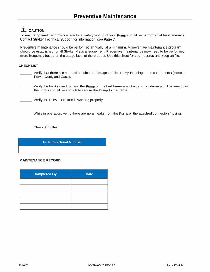
Preventive Maintenance
CAUTION!
To ensure optimal performance, electrical safety testing of your Pump should be performed at least annually.
Contact Stryker Technical Support for information, see Page 7.
Preventive maintenance should be performed annually, at a minimum. A preventive maintenance program
should be established for all Stryker Medical equipment. Preventive maintenance may need to be performed
more frequently based on the usage level of the product. Use this sheet for your records and keep on file.
CHECKLIST
Verify that there are no cracks, holes or damages on the Pump Housing, or its components (Hoses,
Power Cord, and Case).
Verify the hooks used to hang the Pump on the bed frame are intact and not damaged. The tension in
the hooks should be enough to secure the Pump to the frame.
Verify the POWER Button is working properly.
While in operation, verify there are no air leaks from the Pump or the attached connectors/hosing.
Check Air Filter.
Air Pump Serial Number
MAINTENANCE RECORD
Completed By: Date
2016/06 AO-SM-60-20 REV 2.0 Page 18 of 24
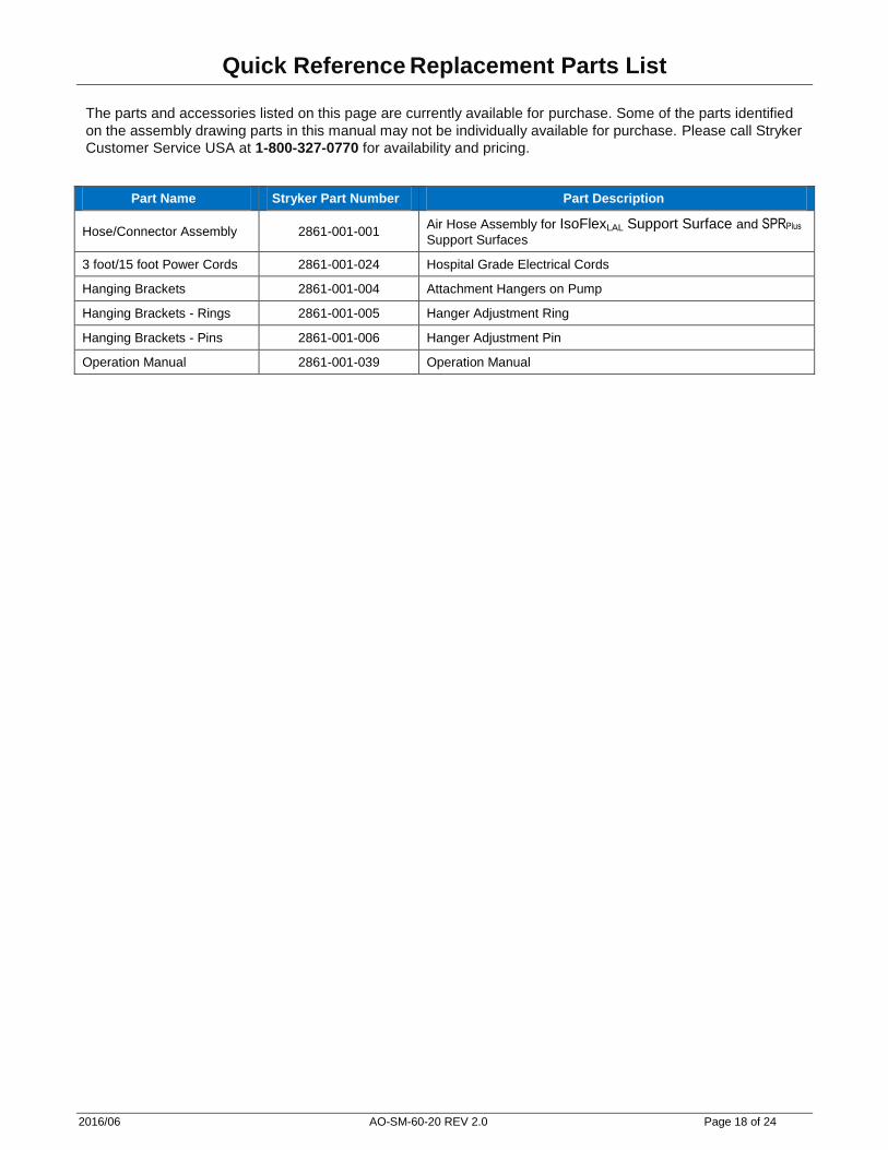
Quick Reference Replacement Parts List
The parts and accessories listed on this page are currently available for purchase. Some of the parts identified
on the assembly drawing parts in this manual may not be individually available for purchase. Please call Stryker
Customer Service USA at 1-800-327-0770 for availability and pricing.
Part Name Stryker Part Number Part Description
Hose/Connector Assembly 2861-001-001 Air Hose Assembly for IsoFlexLAL Support Surface and SPRPlus Support Surfaces
3 foot/15 foot Power Cords 2861-001-024 Hospital Grade Electrical Cords
Hanging Brackets 2861-001-004 Attachment Hangers on Pump
Hanging Brackets - Rings 2861-001-005 Hanger Adjustment Ring
Hanging Brackets - Pins 2861-001-006 Hanger Adjustment Pin
Operation Manual 2861-001-039 Operation Manual
2016/06 AO-SM-60-20 REV 2.0 Page 19 of 24
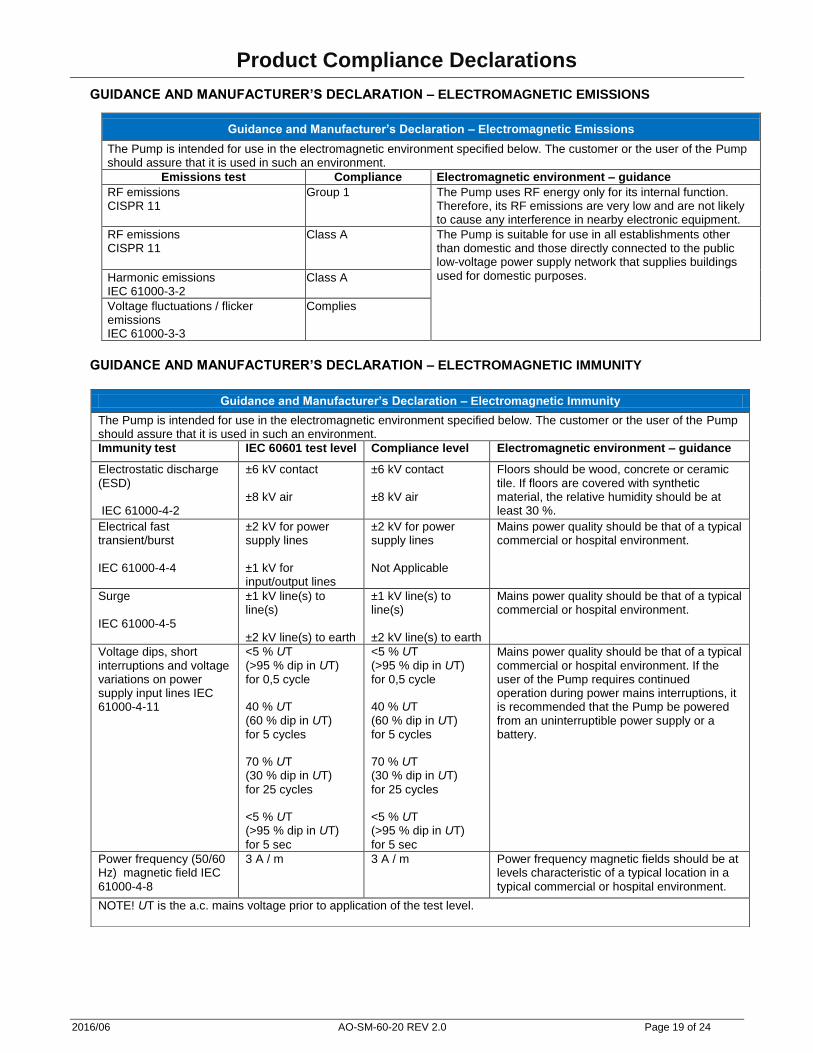
Product Compliance Declarations
GUIDANCE AND MANUFACTURER’S DECLARATION – ELECTROMAGNETIC EMISSIONS
Guidance and Manufacturer’s Declaration – Electromagnetic Emissions
The Pump is intended for use in the electromagnetic environment specified below. The customer or the user of the Pump should assure that it is used in such an environment.
Emissions test Compliance Electromagnetic environment – guidance
RF emissions CISPR 11
Group 1 The Pump uses RF energy only for its internal function. Therefore, its RF emissions are very low and are not likely to cause any interference in nearby electronic equipment.
RF emissions CISPR 11
Class A The Pump is suitable for use in all establishments other than domestic and those directly connected to the public low-voltage power supply network that supplies buildings used for domestic purposes. Harmonic emissions
IEC 61000-3-2 Class A
Voltage fluctuations / flicker emissions IEC 61000-3-3
Complies
GUIDANCE AND MANUFACTURER’S DECLARATION – ELECTROMAGNETIC IMMUNITY
Guidance and Manufacturer’s Declaration – Electromagnetic Immunity
The Pump is intended for use in the electromagnetic environment specified below. The customer or the user of the Pump should assure that it is used in such an environment.
Immunity test IEC 60601 test level Compliance level Electromagnetic environment – guidance
Electrostatic discharge (ESD) IEC 61000-4-2
±6 kV contact ±8 kV air
±6 kV contact ±8 kV air
Floors should be wood, concrete or ceramic tile. If floors are covered with synthetic material, the relative humidity should be at least 30 %.
Electrical fast transient/burst IEC 61000-4-4
±2 kV for power supply lines ±1 kV for input/output lines
±2 kV for power supply lines Not Applicable
Mains power quality should be that of a typical commercial or hospital environment.
Surge IEC 61000-4-5
±1 kV line(s) to line(s) ±2 kV line(s) to earth
±1 kV line(s) to line(s) ±2 kV line(s) to earth
Mains power quality should be that of a typical commercial or hospital environment.
Voltage dips, short interruptions and voltage variations on power supply input lines IEC 61000-4-11
<5 % UT (>95 % dip in UT) for 0,5 cycle 40 % UT (60 % dip in UT) for 5 cycles 70 % UT (30 % dip in UT)
for 25 cycles <5 % UT (>95 % dip in UT)
for 5 sec
<5 % UT (>95 % dip in UT) for 0,5 cycle 40 % UT (60 % dip in UT) for 5 cycles 70 % UT (30 % dip in UT)
for 25 cycles <5 % UT (>95 % dip in UT)
for 5 sec
Mains power quality should be that of a typical commercial or hospital environment. If the user of the Pump requires continued operation during power mains interruptions, it is recommended that the Pump be powered from an uninterruptible power supply or a battery.
Power frequency (50/60 Hz) magnetic field IEC 61000-4-8
3 A / m 3 A / m Power frequency magnetic fields should be at levels characteristic of a typical location in a typical commercial or hospital environment.
NOTE! UT is the a.c. mains voltage prior to application of the test level.
2016/06 AO-SM-60-20 REV 2.0 Page 20 of 24
Product Compliance Declarations
GUIDANCE AND MANUFACTURER’S DECLARATION – ELECTROMAGNETIC IMMUNITY - NON LIFE
SUPPORTING
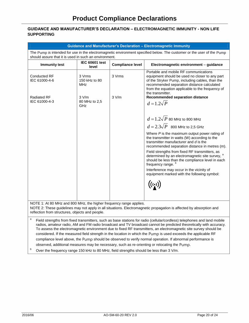
Guidance and Manufacturer’s Declaration – Electromagnetic Immunity
The Pump is intended for use in the electromagnetic environment specified below. The customer or the user of the Pump
should assure that it is used in such an environment.
Immunity test IEC 60601 test
level Compliance level Electromagnetic environment – guidance
Conducted RF IEC 61000-4-6 Radiated RF IEC 61000-4-3
3 Vrms 150 kHz to 80 MHz 3 V/m 80 MHz to 2,5 GHz
3 Vrms 3 V/m
Portable and mobile RF communications equipment should be used no closer to any part of the Stryker Pump, including cables, than the recommended separation distance calculated from the equation applicable to the frequency of the transmitter. Recommended separation distance
Pd 2.1
Pd 2.1 80 MHz to 800 MHz
Pd 3.2 800 MHz to 2,5 GHz
Where P is the maximum output power rating of the transmitter in watts (W) according to the transmitter manufacturer and d is the
recommended separation distance in metres (m).
Field strengths from fixed RF transmitters, as determined by an electromagnetic site survey,
a
should be less than the compliance level in each frequency range.
b
Interference may occur in the vicinity of equipment marked with the following symbol:
NOTE 1: At 80 MHz and 800 MHz, the higher frequency range applies.
NOTE 2: These guidelines may not apply in all situations. Electromagnetic propagation is affected by absorption and reflection from structures, objects and people.
a Field strengths from fixed transmitters, such as base stations for radio (cellular/cordless) telephones and land mobile
radios, amateur radio, AM and FM radio broadcast and TV broadcast cannot be predicted theoretically with accuracy. To assess the electromagnetic environment due to fixed RF transmitters, an electromagnetic site survey should be
considered. If the measured field strength in the location in which the Pump is used exceeds the applicable RF
compliance level above, the Pump should be observed to verify normal operation. If abnormal performance is
observed, additional measures may be necessary, such as re-orienting or relocating the Pump. b Over the frequency range 150 kHz to 80 MHz, field strengths should be less than 3 V/m.
2016/06 AO-SM-60-20 REV 2.0 Page 21 of 24
Product Compliance Declarations
GUIDANCE AND MANUFACTURER’S DECLARATION – RECOMMENDED SEPARATION DISTANCES
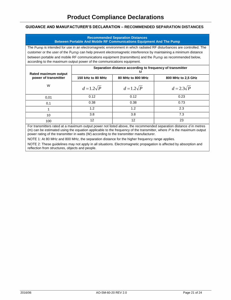
Recommended Separation Distances Between Portable And Mobile RF Communications Equipment And The Pump
The Pump is intended for use in an electromagnetic environment in which radiated RF disturbances are controlled. The
customer or the user of the Pump can help prevent electromagnetic interference by maintaining a minimum distance
between portable and mobile RF communications equipment (transmitters) and the Pump as recommended below,
according to the maximum output power of the communications equipment.
Rated maximum output power of transmitter
W
Separation distance according to frequency of transmitter
M
150 kHz to 80 MHz 80 MHz to 800 MHz 800 MHz to 2,5 GHz
Pd 2.1 Pd 2.1 Pd 3.2
0,01 0.12 0.12 0.23
0,1 0.38 0.38 0.73
1 1.2 1.2 2.3
10 3.8 3.8 7.3
100 12 12 23
For transmitters rated at a maximum output power not listed above, the recommended separation distance d in metres (m) can be estimated using the equation applicable to the frequency of the transmitter, where P is the maximum output power rating of the transmitter in watts (W) according to the transmitter manufacturer.
NOTE 1: At 80 MHz and 800 MHz, the separation distance for the higher frequency range applies.
NOTE 2: These guidelines may not apply in all situations. Electromagnetic propagation is affected by absorption and reflection from structures, objects and people.
2016/06 AO-SM-60-20 REV 2.0 Page 22 of 24
Warranty
LIMITED WARRANTY The Stryker Air™ Pump has a warranty of THREE (3) YEARS under normal use, conditions, and with appropriate periodic maintenance as described in this manual. The Stryker Air™ Pump has an expected service life of FIVE (5) YEARS. This statement constitutes Stryker’s entire warranty with respect to the aforesaid equipment. Stryker makes no other warranty or representation, either expressed or implied, except as set forth herein. There is no warranty of merchantability and there are no warranties of fitness for any particular purpose. In no event shall Stryker be liable here under for incidental or consequential damages arising from or in any manner related to sales or use of any such equipment. CONDITIONS AND LIMITATIONS This statement constitutes Stryker’s entire warranty with respect to the aforesaid equipment. Stryker makes no other warranty or representation, either expressed or implied, except as set forth herein. There is no warranty of merchantability and there are no warranties of fitness for any particular purpose. This warranty does not extend to, nor cover:
− Normal wear and tear; or
− Damage or product failure due to causes beyond Stryker’s control such as, but not limited to abuse, theft, fire, flood, wind, lightning, freezing, clogging of support surface pores due to tobacco smoke, unusual atmosphere conditions, material degradation due to exposure to moisture; or
− Damage to support surface or support surface handles through the use of the support surface for patient transfer or transport.
Normal use is defined as normal hospital or facility usage. Damages arising from abnormal use such as those caused by needle punctures, burns, chemicals, negligent use or improper care or improper cleaning or staining resulting from it are exempt from warranty coverage. TO OBTAIN PARTS AND SERVICE Stryker products are supported by a nationwide network of dedicated Stryker Field Service Representatives. These representatives are factory trained, available locally, and carry a substantial spare parts inventory to minimize repair time. Simply call your local representative or call Stryker Customer Service USA at (800) 327-0770 or (269) 324-6500. RETURN AUTHORIZATION Merchandise cannot be returned without approval from the Stryker Customer Service Department. An authorization number will be provided which must be printed on the returned merchandise. Stryker reserves the right to charge shipping and restocking fees on returned items. Special, modified, or discontinued items not subject to return. DAMAGED MERCHANDISE ICC Regulations require that claims for damaged merchandise must be made with the carrier within fifteen (15) days of receipt of merchandise. Do not accept damaged shipments unless such damage is noted on the delivery receipt at the time of receipt. Upon prompt notification, Stryker will file a freight claim with the appropriate carrier for damages incurred. Claim will be limited in amount to the actual replacement cost. In the event that this information is not received by Stryker within the fifteen (15) day period following the delivery of the merchandise, or the damage was not noted on the delivery receipt at the time of receipt, the customer will be responsible for payment of the original invoice in full. Claims for any short shipment must be made within thirty (30) days of invoice.

2016/06 AO-SM-60-20 REV 2.0 Page 23 of 24
Notes

2016/06 AO-SM-60-20 REV 2.0 Page 24 of 24
Distributed By:
Stryker Medical
3800 E. Centre Ave.
Portage, Michigan 49002
USA


![T/PUMP - Stryker Corporation · T/PUMP COMPONENTS FIGURE 3 - T/PUMP COMPONENTS TOP BOTTOM [11] [10] SERVICE MANUAL TP472 T/PUMP Disconnect pad. Connect ends of the connector hoses](https://static.cupdf.com/doc/110x72/5f12357fec82d372f528b461/tpump-stryker-corporation-tpump-components-figure-3-tpump-components-top.jpg)