300
300
300
A
in cast iron frame
Cast iron swing grate
K&C
vehicle cutdown
Chamber location in
Gutter
House
Stormwater Pipe
Flow
Boundary
Downpipe
Roadway
500
GL (Driveway)
Min. 1200 deep
Chamber for 100Ø outlet
800mm x 300 ID Concrete
450 Min.
700 Min.
Min.
300
K&C
Grass Berm
Footpath
Roadway
House
Stormwater pipe
REGIONAL INFRASTRUCTURE TECHNICAL SPECIFICATION Version: AUGUST 2016Version: AUGUST 2016
CHAMBER PLANSECTION A
SITE PLAN
LONGITUDINAL SECTION
inlet
Nominal 90 mm
Vehicle Crossing
400mm or 600mm deep
Available chamber depths
300x300 ID concrete chamber.
D4.1
uPVC SN16 in berm
STORMWATER BUBBLE UP PIT
outlet as Drawing D6.8
Double catchpit for 225Ø
Drawing D6.9 for 150Ø outlet.
Single catchpit generally as

Road Reserve
Boundary
Kerb and channel
300
20 MPa Concrete
min.
25
Kerb and Channel
Existing
Mountable Option
Boundary
with 'kerb adaptor'
Sweated spigot
with face of kerb
Trim adaptor to make flush
or approved similar
SureCast Metals HCC Kerb Adaptor
100 Ø SN16 uPVC
1.0m
0.3m to
To Fit
20MPa concrete
Cutout - mortar infill
Kerb Outlet
min.
1000
Vehicle Crossing
Depressed Kerb at
Channel Invert
drainage system
Private
if present
Footpath
to channel invert
pipe kerb connection
Cast galvanised steel
with epoxy mortar
Reinstate kerb
Sealed end cap
at Grade 1 in 100
100mm SN16 uPVC pipe
NOTE: DRAWINGS D3.4.2 AND D4.2 HAVE BEEN COMBINED
Version: AUGUST 2016REGIONAL INFRASTRUCTURE TECHNICAL SPECIFICATION
KERB CONNECTION D4.2
KERB ENTRY
VERTICAL KERB
LONGITUDINAL SECTION
35 min.

Water Level
cle
ar of norm
al flo
w
Base of outlet
DN100 SN16 uPVC
Glued or screwed
Factory "T"
REGIONAL INFRASTRUCTURE TECHNICAL SPECIFICATION Version: AUGUST 2016
D4.3
(preferably rip rap, rock or concrete)
Hardening of bank required anti-scour material
uPVC
DN100 SN16
100mm spacings
DN20 holes at
DN 100 STORMWATER OUTLET

50mm Min. 75mm Max.
Gap for flow under fence
H5 200 X 50
100
mm
600
mm Min.
1500mm MIN.
Boundary
100
mm
Note 1
@ 2.4m Spacing (Max.)
Version: AUGUST 2016REGIONAL INFRASTRUCTURE TECHNICAL SPECIFICATION
D4.4- PRIVATE PROPERTY
STORMWATER SECONDARY FLOW PATH TREATMENT
NOTES:
For 10 year ARI flow velocities:
>1.5 m/s Hardening is required
1.0 - 1.5 m/s reinforcing is required
< 1.0 m/s grass cover is sufficient1.
50mm

K&
C
Gutter
House
Stormwater Pipe
Downpipe
sealed surface
Grate inlet for
House
overland flow path
To connection or
Porous well liner
Porous well liner
Porous well liner
Downpipe
Downpipe
REGIONAL INFRASTRUCTURE TECHNICAL SPECIFICATION Version: AUGUST 2016
D4.5PRIVATE PROPERTY
GROUNDWATER RECHARGING DEVICES
SITE PLAN
LONGITUDINAL SECTION
Stormwater connection
Council Storm
water
with overflow
Soakage Catchpit

Footpath
2500 radius (approx.)
Invert
Footpath dish channel in berm.
200 200
700 Min.
500 Min.
200
Footpath
1500 (Typical)
In-situ concrete base
225
150
In-situ concrete apron
225Ø RCRRJ - class 4 pipe
1500 (
Typical)
300
475
1500 400 1500
REGIONAL INFRASTRUCTURE TECHNICAL SPECIFICATION Version: AUGUST 2016
D4.6FOOTPATH BERM CATCHPIT DETAILS
SECTION A
A
PLAN
RCRRJ pipe. See Note 1.
Cast iron grate to fit socket of 225Ø
grade (Min.)
Type HS2 bedding 1:100
150Ø uPVC pipe on NOTES:
2.
1.
minimum 28 day strength of 20MPa.
All in-situ concrete shall have a
of dish channel.
iron grate set 25mm below invert
Top of 225Ø RCRRJ pipe and cast
Concrete haunching
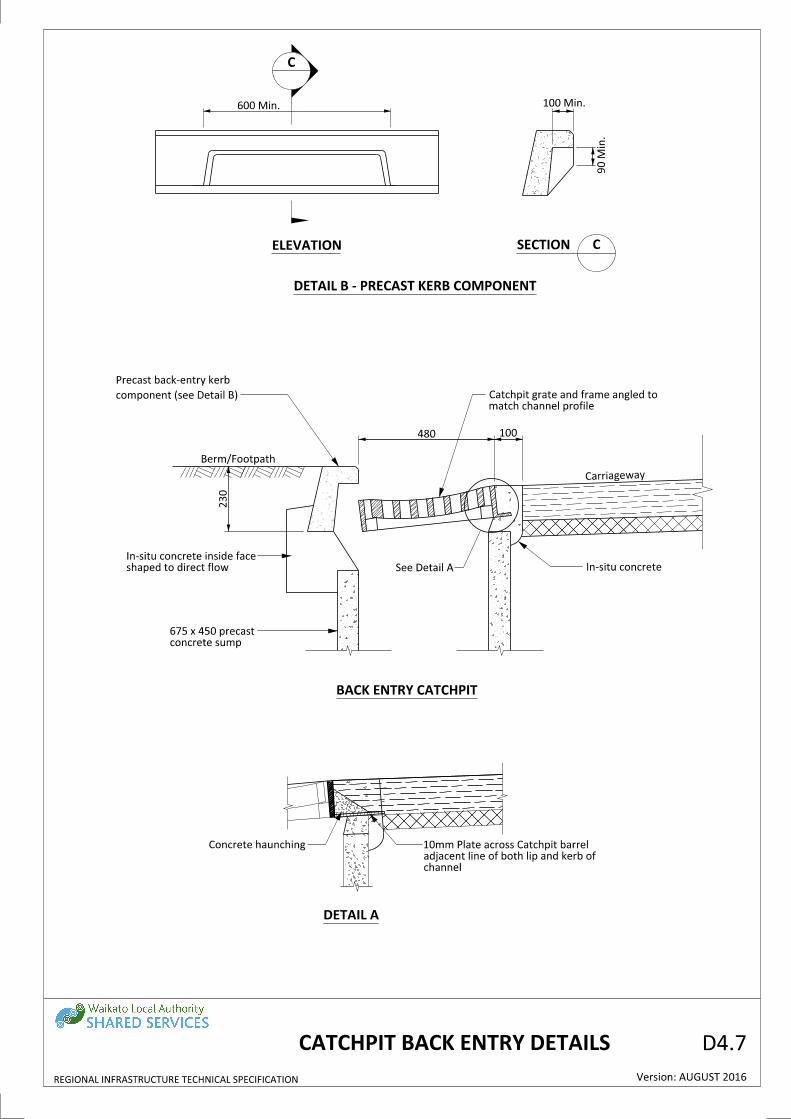
480 100
230
Carriageway
In-situ concrete
concrete sump
675 x 450 precast
Berm/Footpath
600 Min. 100 Min.
90 Min.
REGIONAL INFRASTRUCTURE TECHNICAL SPECIFICATION Version: AUGUST 2016
CATCHPIT BACK ENTRY DETAILS D4.7
DETAIL A
BACK ENTRY CATCHPIT
ELEVATION
See Detail A
match channel profile
Catchpit grate and frame angled to
channel
adjacent line of both lip and kerb of
10mm Plate across Catchpit barrel
DETAIL B - PRECAST KERB COMPONENT
component (see Detail B)
Precast back-entry kerb
C
SECTION C
shaped to direct flow
In-situ concrete inside face

kerb component
Precast back entry
(Perpendicular slots), for cycle routes
Alternative cast iron grate configuration
KERB
CHANNEL
500Steel plate
FALL
central over pipe)
(i.e. back of grate
300 to ID
WATER LEVEL
pipe outlet
1800
225
150
150450
700 Min.
400 Cast insitu concrete base
REGIONAL INFRASTRUCTURE TECHNICAL SPECIFICATION Version: AUGUST 2016
D4.8DOUBLE SUMP CATCHPIT DESIGN
PLAN
SECTION
upstream pit only
component with no bar on
Precast back-entry kerb
See Drawing D4.10
fish (Giant Kokopu)
Degreased aluminium
(on upstream pit)
with no back-entry cavity
Precast kerb component
Min.
600
precast unit
or 675 X 450
600 Ø Class 2
RC pipe
Min. 300 Ø
See Drawing D6.9
Floatables baffle
See Drawing D6.7
Construction details
NOTES:
For details see Drawing D6.7
strength of 20MPa
All in-situ concrete shall have a minimum 28 day
epoxy or approved equivalent.
Epoxy product to be "ramset epcon C6" 2 pot
Cast iron grate with parallel slots shown in drawing.
4.
3.
2.
1.

B
B
SCALE 1:25
A A
Steel Sheet
1.6mm Stainless
(perpendicular slots) for cycle routes
Alternative cast iron grate configuration
225mm Ø
Minimum outlet
Top of Kerb
Carriageway
1800
600 min
150
Carriageway
Channel
Kerb
500
225
150
600 Min.
150
REGIONAL INFRASTRUCTURE TECHNICAL SPECIFICATION Version: AUGUST 2016
D4.9VERTICAL ENTRY CATCHPIT
50
600
normal grade
Grate set flush with
precast unit
675 x 450
600Ø Class 2 or
and Frame
Catchpit Sump Grate
rod alignment
Holes to match
See Drawing D4.10
clean prior to fixing fish icon.
(Giant Kokopu) Stiff brush
Degreased Aluminium Fish
SECTION A-A
Not to Scale
FLOATABLES BAFFLE DETAIL
SCALE 1:25
PLAN
epoxied into sump wall
nut and spring washer,
6mm galvanised rods,
to chamber wall with
Floatables baffle fixed
soffit of outlet
top to be level with
Floatables baffle
SECTION B-B
SCALE 1:25
NOTES:
3.
2.
1.
strength of 20MPa
All in-situ concrete shall have a minimum 28 day
epoxy or approved equivalent.
Epoxy product to be "Ramset Epcon C6" 2 pot
Cast iron grate with parallel slots shown in drawing.

REGIONAL INFRASTRUCTURE TECHNICAL SPECIFICATION Version: AUGUST 2016
D4.10FISH SYMBOLS FOR CATCHPITS
GIANT KOKOPU
70
- 8
0m
m
220 mm
SOAK AWAY
BUBBLE UP
75
mm
75
mm
250mm
50
mm
50
mm
BLUE NZ NATIVE KOKOPU
NOTES:
Plates to be orientated for reading from road side.
Giant Kokopu Plate to be cast in aluminium - from catchpit suppliers.
5.
4.
3.
2.
1.

A
Carraige
way
Edge of seal
Footp
ath
Berm
0.25mm polypropylene liner
Subsoil drain
Carriageway
Edge of sealFootpath
Min. 900 Min. 600 Min. 900
If mownIf planted
3
1 15
Topsoil
Filter cloth
50 min.
50 min.
Section 4.2.24
Plant following
Section 4.2.18
per m where required in accordance with
min. 100mm PVC with 8 x 10mmØ holes
Slope dependent gravel underdrain with
50 min.
pipe network
Connection to
8 x 10mm Ø holes per meter
with min. 100mm PVC with
Optional gravel underdrain
REGIONAL INFRASTRUCTURE TECHNICAL SPECIFICATION Version: AUGUST 2016
D4.11SWALE PLAN AND SECTION
PLAN
SECTION A
Min. 0.5
% Gra
de
Refer Drawing D.3.3.3
Edge restraint
liner for detention only applications
Optional 0.25mm polypropylene
300
with scruffy dome
DN1050mm Manhole
Refer Drawing D3.3.3
Edge restraint with haunching
Min. 900 Min. 600 Min. 900
NOTES:
4.
3.
2.
1.
Preferred water main location is at edge of footpath.
Private sites on same side of road as swale shall discharge via pipe to invert of swale.
Private sites shall have on-site retention.
For single sloping carriageway, private discharge on opposite side of road shall be kerb discharge.
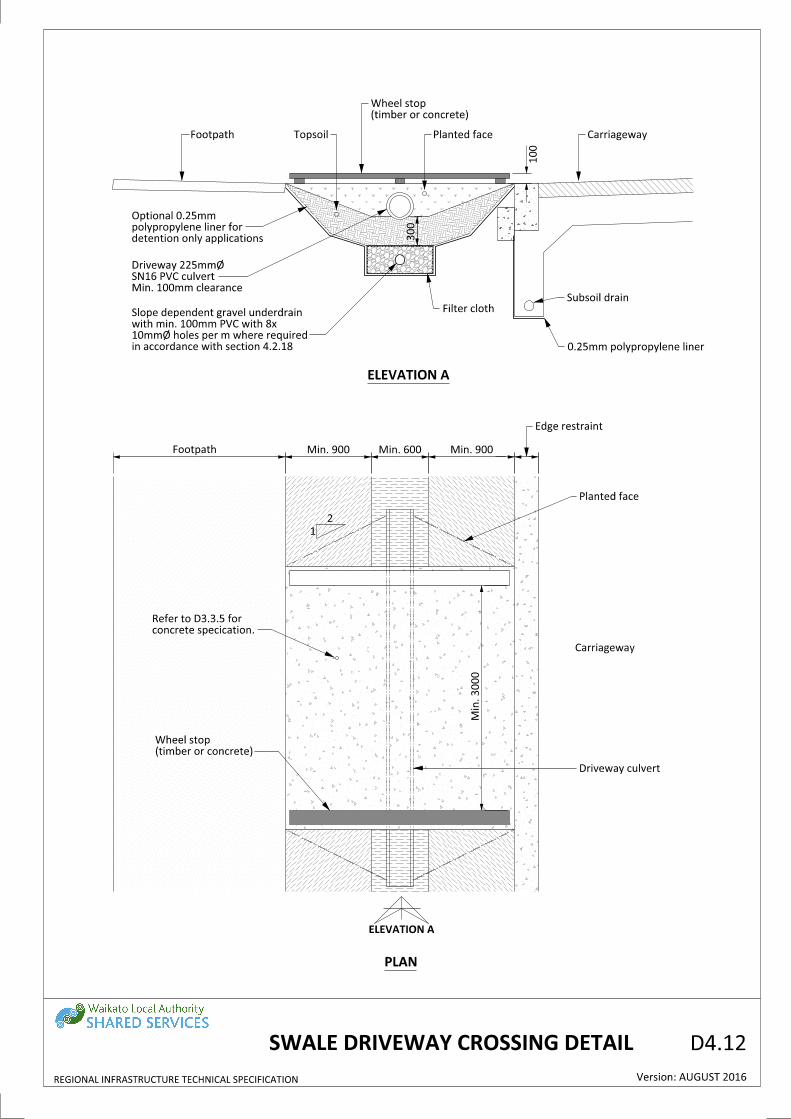
TopsoilFootpath Planted face Carriageway
Subsoil drain
0.25mm polypropylene liner
Filter cloth
Planted face
Driveway culvert
(timber or concrete)
Wheel stop
concrete specication.
Refer to D3.3.5 for
2
1
Edge restraint
Carriageway
Min. 900Min. 600Min. 900Footpath
Min. 3000
(timber or concrete)
Wheel stop
detention only applications
polypropylene liner for
Optional 0.25mm
Min. 100mm clearance
SN16 PVC culvert
Driveway 225mmØ
in accordance with section 4.2.18
10mmØ holes per m where required
with min. 100mm PVC with 8x
Slope dependent gravel underdrain
300
REGIONAL INFRASTRUCTURE TECHNICAL SPECIFICATION Version: AUGUST 2016
D4.12SWALE DRIVEWAY CROSSING DETAIL
PLAN
ELEVATION A
ELEVATION A
100

A
Footpath
Vegetation
Carriageway Footpath
100mmØ
point minimum
Capped flushing
invert of channel
Standard catchpit at
Vertical kerb & channel
protection during construction
Temporary timber barrier for
invert of Channel
Standard catchpit at
champher at each end
to lip of channel with 45°
Vertical kerb champhered
Rip rap armour
4.14
PLAN
UNDERDRAIN LONG SECTION
B
B
Refer to Drawing D3.3.3
channel surround
Vertical kerb and
Parking Bays
Parking Bays
channel profile
to raised kerb and sloped
Champhered kerb and channel
Not to Scale
Refer Detail B Drawing 4.14
Raised kerb with sloped channel
Capped flushing point
Perforated underdrain
Perforated underdrain
optional tree
In-situ soil with
REGIONAL INFRASTRUCTURE TECHNICAL SPECIFICATION
D4.13
Version: AUGUST 2016
UNDERDRAIN LONG SECTION
RAIN GARDEN PLAN AND

85
75
125
200
425
Standard kerb & channel
Carriageway
Rip rap armourFootpath
150mm
Rip rap armourFootpath
150mm
Concrete sides (Precast)
Carraigeway
Standard kerb & channel
on media surface
Non floating mulchRefer detail
Sloped kerb
refer to HCC guideline
media. For specification
Min. 500mm deep
drainage layer
rock 16mm to 40mm
Min. 300mm washed drain
sand transition layer
Cleaned well graded
underdrain
100mm PVC
Perforateddetention only applications
polypropylene liner for
Optional 0.25mm
polypropylene liner
Subsoil drain and 0.25mm
transition layer
well graded sand
Min. 100mm cleaned
on media surface
Non floating mulch
HCC guideline
For specification refer to
Min. 500mm deep media.
holes per m
with 8 x 10mm Ø
PVC underdrain
Perforated 100mm
detention only applications
polypropelene liner for
Optional 0.25mm
drainage layer
rock 16mm to 40mm
Min. 300mm washed drain
polypropylene liner
Subsoil drain and 0.25mm
side
Precast concrete
Refer detail
Sloped kerb
REGIONAL INFRASTRUCTURE TECHNICAL SPECIFICATION Version: AUGUST 2016
D4.14SECTIONS AND KERB DETAIL
RAIN GARDEN CROSS
50 Min.
50 Min.
A
Not to Scale
CROSS SECTION - VERTICAL SIDES
A
Not to Scale
CROSS SECTION - SLOPED SIDES
Not to Scale
DETAIL B - KERB WITH SLOPED CHANNEL
A
-
Footpath
High flow bypass
Road centre lin
e
Kerb a
nd c
hannel
Kerb a
nd c
hannel
Pro
pert
y b
oundary
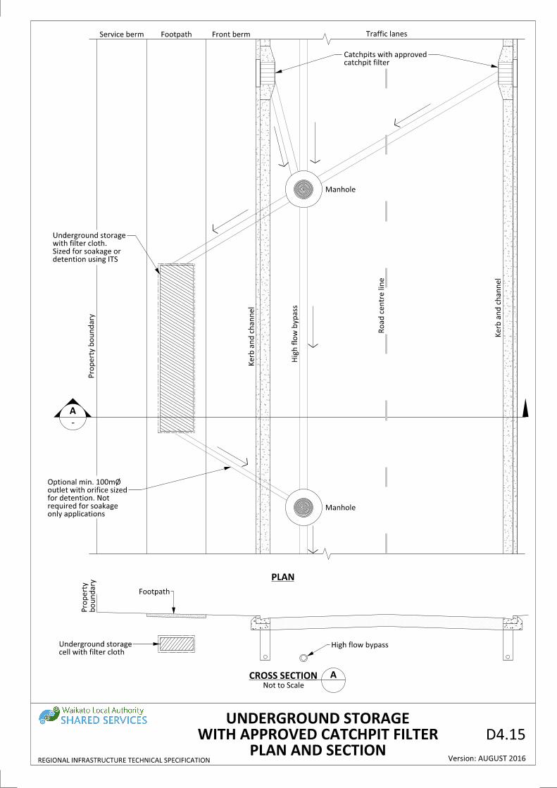
Traffic lanesFront bermFootpathService berm
Manhole
boundary
Pro
pert
y
cell with filter cloth
Underground storage
Manhole
catchpit filter
Catchpits with approved
only applications
required for soakage
for detention. Not
outlet with orifice sized
Optional min. 100mØ
Hig
h flo
w b
ypass
ACROSS SECTIONNot to Scale
PLAN
detention using ITS
Sized for soakage or
with filter cloth.
Underground storage
REGIONAL INFRASTRUCTURE TECHNICAL SPECIFICATION
D4.15
Version: AUGUST 2016PLAN AND SECTION
WITH APPROVED CATCHPIT FILTER
UNDERGROUND STORAGE

Manhole
High flow bypass
Manhole
catc
hpit filter
Catc
hpit with a
ppro
ved
pipe to underground storage
Bypass invert set at soffit of
or detention using ITS.
filter cloth. Sized for soakage
Underground storage cell with
applications.
Not required for soakage only
with orifice sized for detention.
Optional minimum 100mmØ outlet
REGIONAL INFRASTRUCTURE TECHNICAL SPECIFICATION Version: AUGUST 2016
D4.16CATCHPIT FILTER LONG SECTION
UNDERGROUND STORAGE WITH APPROVED
conditions are suitable for soakage.
conditions are suitable. Consult a Geotechnical Engineer to determine if ground
Underground storage can provide soakage and detention requirement if ground
Note:

REGIONAL INFRASTRUCTURE TECHNICAL SPECIFICATION Version: AUGUST 2016
D4.17LONG SECTION
UNDERGROUND STORAGE WITH GROSS POLLUTANT TRAP
conditions are suitable for soakage.
conditions are suitable. Consult a Geotechnical Engineer to determine if ground
Underground storage can provide soakage and detention requirement if ground
Note:
Manhole
trap
Gro
ss p
olluta
nt
Catc
hpit
High flow bypass
applications.
Not required for soakage only
with orifice sized for detention.
Optional minimum 100mmØ outlet
or detention using ITS.
filter cloth. Sized for soakage
Underground storage cell with
pipe to underground storage
Bypass invert set at soffit of
Manhole

D4.18STORMWATER CONNECTIONS LAYOUT
REGIONAL INFRASTRUCTURE TECHNICAL SPECIFICATION Version: AUGUST 2016
Council OwnershipKEY: Private Ownership
soakage trench
soakhole or
Privately owned
Property boundaries
Soakage
SINGLE PROPERTY SINGLE PROPERTY
Service Pipe
Property boundaries
at boundary
Point of discharge
Stormwater Main
measure (WEM)
SINGLE PROPERTY
Service Pipe
Property boundaries
stub. See D4.5
Point of discharge
MainStormwater
measure (WEM)
SUBDIVISION
boundaries
the serviced
discharge at
Point of
Point of discharge at the
buildings
run underneath
as services cannot
de-commisioned,
Old service pipe
pipe
New service
Stormwater Main
dwelling
for new Lot/
Retain original
House
New
House
WEM
WEM
Accessway
5+ CUSTOMERS
boundaries
Point of discharge at
Stormwater Main
of blockages
Manhole required for
Single Lot
5+ CUSTOMERS
anoth
er
manhole
is r
equir
ed
If g
reate
r th
an 1
20m
, th
en
Stormwater Main
WEM
catchpit
Stormwater
at boundary
discharge
Point of
soakage trench if possible
Privately owned soakhole or

31
1050Ø Chimney
Slab
Chamber
Manhole
450
450
1800 Length m
ax
23
450
250
150
Precast flanged base
150
(Max)600
(Max)600
80
300
300
Manhole top slab
Precast flanged base
DETAILS DN1350 AND OVER MANHOLES
Manhole top slab
31
450
DROP MANHOLES
top slabManhole
top slab
Manhole
Precast flanged base
DN1050 - DN1350 MANHOLES
DETAILS DN1050 & DN1200 MANHOLES
ground.
length 300mm into undisturbed
100deep with 4/12 bars min.
Concrete slab 450wide x
NOTES:
90° PVC junction
jointing
BM100
150
do not sponge
trowel finish,
Smooth steel
above sewer)
(invert minimum 100mm
50mm channel in benching
Internal PVC drop
pattern (detail required)
Cover to be HCC standard
extension 300mm
Maximum neck
section
pre-cast
2.4m
to be
First lift
THROUGH MANHOLE
TYPICAL PLAN CURVE
Version: AUGUST 2016
Ladder rung
REGIONAL INFRASTRUCTURE TECHNICAL SPECIFICATION
(Min)
225
Radius minimum 2.5 x Pipe Ømm
D4.21
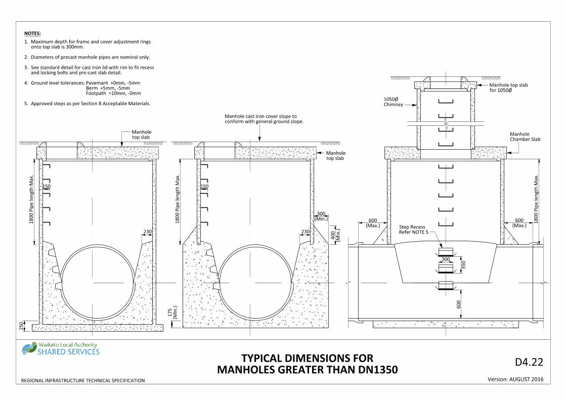
Footpath +10mm, -0mm
Berm +5mm, -5mm
Pavemant +0mm, -5mmGround level tolerances:
and locking bolts and pre-cast slab detail.
See standard detail for cast iron lid with rim to fit recess
Stormwater manholes may use concrete.
Wastewater manholes to use ceramic for channelling.
Diameters of precast manhole pipes are nominal only.
4.
3.
2.
1.
with ground slope.
Cover slope to conform
Chamber Slab
Manhole
Chimney
1050Ø
1800 Pip
e length M
ax.
150
230
(Min.)
300
(Min.)
400
for 1050Ø
Manhole top slab
Refer NOTE 5.
Step Recess (Max.)
600 1800 Pip
e length M
ax.
300
350
600
250
1800 Pip
e length M
ax.
150
230
top slab
Manhole
top slab
Manhole
(Min.)
175
(Max.)
600
MANHOLES GREATER THAN DN1350
TYPICAL DIMENSIONS FOR
Version: AUGUST 2016
NOTES:
Approved steps as per Section 8 Acceptable Materials.
Footpath +10mm, -0mm
Berm +5mm, -5mm
Pavemant +0mm, -5mmGround level tolerances:
and locking bolts and pre-cast slab detail.
See standard detail for cast iron lid with rim to fit recess
Diameters of precast manhole pipes are nominal only.
onto top slab is 300mm.
Maximum depth for frame and cover adjustment rings
5.
4.
3.
2.
1.
REGIONAL INFRASTRUCTURE TECHNICAL SPECIFICATION
conform with general ground slope.
Manhole cast iron cover slope to
D4.22

1
1
shallow chamber
Top slab for DN750
75 75
872
DN750
DN750 INTERNAL SHALLOW CHAMBER
TOP SLAB FOR DN750 SHALLOW CHAMBER
and where depth of invert is less than 1000mm
To be used only on pipes of DN100 to DN300
Version: AUGUST 2016
SHALLOW MANHOLE/CHAMBER
585Ø (Min.)
(Min.)
250
reinforcing bars
2/12Ø Circular 320 lap
1000 (
Max.)
cover with rim to fit recess
Standard HCC pattern cast iron
No steps
REGIONAL INFRASTRUCTURE TECHNICAL SPECIFICATION
D4.23
Footpath +10mm, -0mm
Berm +5mm, -5mm
Pavemant +0mm, -5mmGround level tolerances:
NOTES:
1.
(refer to Note 1)
Ground level tolerances

LATERAL CONNECTION
Plain bend
Road B
dy
Boundary
Ground level
Ground level
'Y' junction
BoundaryFlow
Trench
Trench
Main
Main
uPVC Pipes
Min. fall 1 in 60 (1.667%)
100mm Ø lateral
Green = Stormwater
Red = Wastewater
Seal end with painted screw on end cap
Green = Stormwater
Red = Wastewater
Seal end with painted screw on end cap
Green = Stormwater
Red = Wastewater
Seal end with painted screw on end cap
uPVC Pipes
the Lot the connection serves.
fitting when main is located within
(1) Public pipe to end of junction
Min. fall 1 in 60 (1.667%)
100mm Ø lateral
uPVC Pipes
Version: AUGUST 2016
RAMP RISER CONNECTION WITH A DEPTH TO INVERT GREATER THAN 2500mm - SECTION
CL
CL
STANDARD CONNECTION WITH A DEPTH TO INVERT LESS THAN 2500mm - SECTION
Lot the connection serves.
when main is located outside the
(2) Public pipe to road boundary
POINT OF DISCHARGE: PUBLIC AND PRIVATE INFRASTRUCTURE
Main
POINT
*ACCESS
access points.
Building Code for the allowable types of
* Rodding point shown. Refer New Zealand
POINT
*ACCESS
access points.
Building Code for the allowable types of
* Rodding point shown. Refer New Zealand
1.0m Max.
300mm Min.
1.0m Max.
300mm Min.
Length varies
2500 m
ax
Gre
ater th
an 2
500
Length varies
REGIONAL INFRASTRUCTURE TECHNICAL SPECIFICATION
D4.24
green (Stormwater)
Top 100mm of post painted red (Wastewater) or
from connection to 300mm above ground level.
50 x 50 wooden marker and marker tape to extend
London junction
green (Stormwater)
Top 100mm of post painted red (Wastewater) or
from connection to 300mm above ground level.
50 x 50 wooden marker and marker tape to extend
London junction
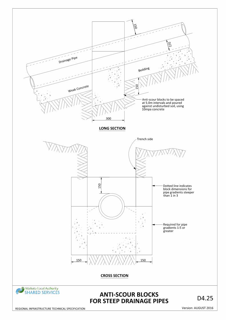
Bedding
300
D/2
150
150
Drainag
e Pipe
Trench side
150
150150
Weak Con
crete
CROSS SECTION
LONG SECTION
Version: AUGUST 2016
10mpa concrete
against undisturbed soil, using
at 5.0m intervals and poured
Anti-scour blocks to be spaced
than 1 in 3
pipe gradients steeper
block dimensions for
Dotted line indicates
greater
gradients 1:5 or
Required for pipe
FOR STEEP DRAINAGE PIPES
ANTI-SCOUR BLOCKS
REGIONAL INFRASTRUCTURE TECHNICAL SPECIFICATION
D4.25

NOTES:
1.
2.
3.
4.
5.
6.All piles located within the 45° influence envelope shall be drilled.
pipe for the first row of piles.
appropriate) outside of the 45° influence envelope and below the invert level of the sewer
wastewater/stormwater assets. All structural loads shall be absorbed (by means of piles where
No structural loads shall be placed on, or be transferred to the public pipelines, or other public
as a result of any work close to or over Council's assets.
Closed Circuit Television (CCTV) inspections shall be required of Council's assets before and after
Building is not permitted over manholes or connections under any circumstances.
See section ABC & XYZ for more information.
or renewed in place with approved pipe materials at a cost to the development.
Where required by Council, the affected public pipelines or structures shall either be relocated
be so designed that they act independently of the public sewer or stormwater network.
by Council so shall be avoided. Where this is not possible, the building and development shall
Building or other works over public sewer or stormwater pipelines is not a practice supported
Manhole
Piles
Ground Level
Ground Level
influence lin
e
1000 Min. belo
w
influence lin
e
1000 Min. belo
w
pip
e invert
1000 Min. belo
w
clearance
1500 Min. Pile
clearance
1500 Min. Pile
Manholemanhole structure
Outside wall of the
ZONE OF INFLUENCE
See Note 2.
manhole structure
Outside wall of the
Public Main
Public Main
clearance
Pile
1500 Min.
Version: AUGUST 2016
Retaining Post
First row of piles
of piles
Subsequent row
Piles
PLAN: BUILDING OVER A PUBLIC MAINPLAN: BUILDING ADJACENT TO A PUBLIC MAIN
(Only permitted if an alternative alignment is not possible)
Building envelope Building envelope
45° Influ
ence Lin
e
ELEVATION
InvertPipe
pip
e invert
1000 Min. belo
w
clearancepile
1500 Min.
clearancepile
1500 Min.
Founding Level
Founding Level
as shown
supported by piles founded
All superstructures shall be
cleara
nce
2000 Min.
cleara
nce
2000 Min.
Founding Level
PUBLIC WASTEWATER OR STORMWATER PIPELINES
BUILDING OVER AND ADJACENT TO
REGIONAL INFRASTRUCTURE TECHNICAL SPECIFICATION
D4.26


![Telecommunication Products - Trendtek jointing pits.pdf · [01] UG2006 - P6 Pit UG2007 - P7 Pit UG2008 - P8 Pit UG2900 - P9 Pit UG2001 - P1 Pit UG2002 - P2 Pit UG2003 - P3 Pit UG2004](https://static.cupdf.com/doc/110x72/5a7969077f8b9ab9308d3433/telecommunication-products-jointing-pitspdf01-ug2006-p6-pit-ug2007-p7-pit.jpg)