GESTRASteam Traps and Steam Trap Testing
For all applications
2
The GESTRA Steam Trap Range
The three different steam trap types
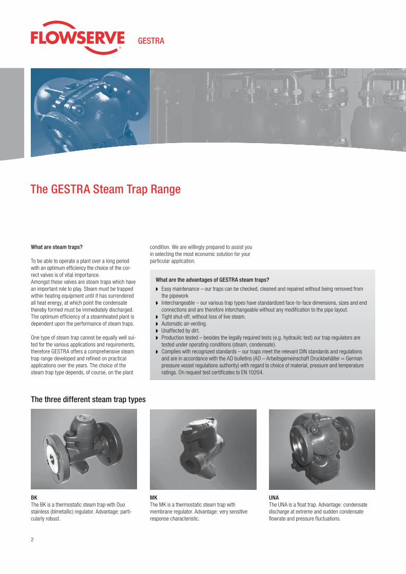
BKThe BK is a thermostatic steam trap with Duo stainless (bimetallic) regulator. Advantage: parti-cularly robust.
MKThe MK is a thermostatic steam trap with mem brane regulator. Advantage: very sensitive response characteristic.
UNAThe UNA is a float trap. Advantage: condensate discharge at extreme and sudden condensate flowrate and pressure fluctuations.
condition. We are willingly pre pared to assist you in selecting the most economic solution for your parti cular application.
What are steam traps?
To be able to operate a plant over a long period with an optimum efficiency the choice of the cor-rect valves is of vital im portance.Amongst these valves are steam traps which have an important role to play. Steam must be trapped within heating equipment until it has surrendered all heat energy, at which point the condensate thereby formed must be imme diately dis charged. The optimum efficiency of a steam heated plant is dependent upon the performance of steam traps.
One type of steam trap cannot be equally well sui-ted for the various applications and requirements, therefore GESTRA offers a com prehensive steam trap range develop ed and refined on practical appli ca tions over the years. The choice of the steam trap type depends, of course, on the plant
What are the advantages of GESTRA steam traps?
◗ Easy maintenance – our traps can be checked, cleaned and repaired without being removed from the pipework
◗ Interchangeable – our various trap types have standardized face-to-face dimen sions, sizes and end connections and are therefore interchangeable without any modification to the pipe layout.
◗ Tight shut-off, without loss of live steam.◗ Automatic air-venting.◗ Unaffected by dirt.◗ Production tested – besides the legally required tests (e.g. hydraulic test) our trap regulators are tested under operating conditions (steam, condensate).◗ Complies with recognized standards – our traps meet the relevant DIN stand ards and regulations
and are in accord ance with the AD bulletins (AD – Arbeits ge mein schaft Druckbehälter = German pres sure vessel regulations authority) with regard to choice of material, pres sure and temperature ratings. On request test certificates to EN 10204.
3
Criteria
Steam trap typesTr
ap ty
pe B
K w
ith b
imet
allic
re
gula
tor
Trap
type
MK
with
mem
bran
e re
gula
tor
Ball
float
trap
type
UN
A w
ith D
uple
x co
ntro
l
Ball
float
trap
type
UN
A w
ith S
impl
ex
cont
rol
Please note
1. Operation with different condensates
2. Different modes of operation
3. Operation with back pressure
4. Sensitivity to dirt
5. Air-venting
6. Condensate discharge at definite temperatures
7. Frost resistance
8. Condensate discharge without loss of live steam
9. Resistance to waterhammer
10. Non-return valve action
11. Application in vacuum
12. Installation in any position
13. Easy of maintenance
14. Service life of control unit
15. Use with superheated steam
Condensate from steam
Condensate from compressed air
Condensate, distillate from chemical products
Continuous operation: Constant formation of condensate; flowrate and pressure vary
Discontinuous operation: Intermittent formation of condensate; flowrate and pressure vary strongly
Any operation: Heat exchanger may becontrolled on the steam side
Up to approx. 30% of upstream pressure
From 30 % to 60 % of upstream pressure
More than 60 % of upstream pressure
Highly contaminated condensate
Automatic
Condensate temperature nearly boiling temperature
Condensate undercooling approx. 30 K (required)
Condensate undercooling adjustable
Intermittent condensate formation
Reduced condensate formation (< 10 kg/h)
Continuous condensate formation (> 10 kg/h)
1
–
–
2
2
3**
1
3*
3*
1
1
2*
1*
2*
1
1
1
1
1
1
3
1
1
1
1
1
–
–
1
1
2
1
1
1
1
1
2**
1**
–
1
1
1
1
1*
1*
2
1
1
2
3
1
–
–
1
1
1
1
1
1
1
1
1
–
–
1*
1
1
1
3*
–*
1
–*
1
1
3*
1
1
1
1
3*
3*
1
1
1
1
3*
1
–
–
3*
1
1
1
3*
–*
1
–*
1
1
1
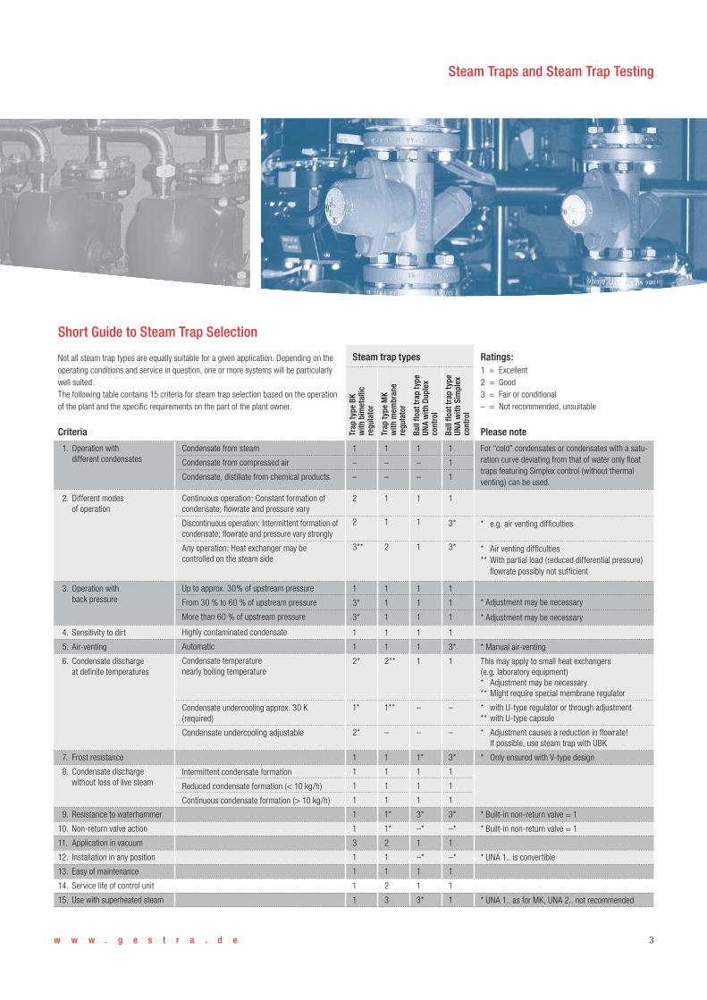
For “cold” condensates or condensates with a satu-ration curve deviating from that of water only float traps featuring Simplex control (without thermal venting) can be used.
* e.g. air venting difficulties
* Air venting difficulties** With partial load (reduced differential pressure) flowrate possibly not sufficient
* Adjustment may be necessary
* Adjustment may be necessary
* Manual air-venting
This may apply to small heat exchangers (e.g. laboratory equipment)* Adjustment may be necessary** Might require special membrane regulator
* with U-type regulator or through adjustment** with U-type capsule
* Adjustment causes a reduction in flowrate! If possible, use steam trap with UBK
* Only ensured with V-type design
* Built-in non-return valve = 1
* Built-in non-return valve = 1
* UNA 1.. is convertible
* UNA 1.. as for MK, UNA 2.. not recommended
Ratings:1 = Excellent2 = Good3 = Fair or conditional– = Not recommended, unsuitable
Not all steam trap types are equally suitable for a given application. Depending on the operating conditions and service in question, one or more systems will be particularly well suited.The following table contains 15 criteria for steam trap selection based on the operation of the plant and the specifi c requirements on the part of the plant owner.
Short Guide to Steam Trap Selection
w w w . g e s t r a . d e
Steam Traps and Steam Trap Testing

4
Thermostatic steam traps with Duo stainless steel (bimetallic) regulator Pressure ratings up to PN 630.
For roughest operating conditions. Unexcelled service life.
Operating principle resulting in a sturdy design unaffected by water hammer and frost.
May also be used as air vents.
Operation
Opening and closing are controlled by the tempe-rature sensor of Duo stainless steel plates and the stage nozzle operating together. During start-up of the plant and in the presence of cold condensate and air the Duo stainless steel plates are flat. The service pressure acts in the opening direction, the valve is completely open.
With rising condensate temperature the plates de-flect and draw the stage nozzle towards the closed position (a thermostatic process). The service pressure and the pressure built up in the stage-nozzle chamber by flashing produce an opposite force (a thermodynamic process). The orifice area is determined by the prevailing state of equilibrium between the temperature-dependent closing force and the pressure-related opening force.
Immediately below saturation temperature (boiling temperature) the plates are deflected to such an extent that the stage nozzle is almost closed. As a consequence the pressure in the stage-nozzle chamber decreases and breaks down as the flashing across the stage nozzle then closes.The deflection of the Duo stainless steel plates created by the temperature is not sufficient to produce, over the complete pressure range, the force required to count eract the force acting on the stage nozzle in the opening direction. The plates are therefore arranged in a stack which acts as a spring having a characteristic that adapts itself to the force acting on the stage nozzle varying with the service pressure. Thermostatic and spring cha-racteristics are balanced so that the opening and closing temperatures are always just a few degrees below saturation temperature.
Duo Steam Traps BK

5
Thermovit regulator ◗
Light and compact regulator unit, replace-able without removing body from pipeline. Withstands waterhammer and freezing. Easy maintenance
Large-surface strainer ◗
Stage nozzle ◗
Thermodynamic control. Wear resistant. Freely mounted for non-return valve action
Temperature feeler ofDuo stainless steel plates ◗
Thermostatic control. Corrosion-resistant throughout, fatigue-free, not subject to ageing
Rhombus-shaped cover ◗
secured with only two bolts, which are easy to insert and easy to use in restricted spaces
Metal base bushing◗
Recessed flat gasket for superior sealing
◗
w w w . g e s t r a . d e
Steam Traps and Steam Trap Testing

6
BK Types and Connections
The BK traps at a glance
Type
BK 45
BK 15
BK 46
BK 37
BK 27 N
BK 28
BK 29
BK 212-F91
BK 37-ASTM
BK 28-ASTM
BK 29-ASTM
BK 212-ASTM
Max. differ- ential pressurebar (psi)Material
Connections, DN
Flanged Screwed Socket-weld Butt-weld
1.0460
1.0460
1.5415
1.5415
1.5415
1.5415
1.7335
1.7383/1.4903
A182-F-12
A182-F-12
A182-F-12
A182-F-22
22 (320)
22 (320)
32 (465)
45 (650)
45 (650)
85 (1230)
110 (1600)
250 (3625)
45 (650)
85 (1230)
110 (1600)
250 (3625)
15–25 mm (1/2"–1")
40–50 mm (1 1/2"–2")
15–25 mm (1/2"–1")
15–25 mm (1/2"–1")
40–50 mm (1 1/2"–2")
15–25 mm (1/2"–1")
15–25 mm (1/2"–1")
15–25 mm (1/2"–1")
15–25 mm (1/2"–1")
15–25 mm (1/2"–1")
15–25 mm (1/2"–1")
15–25 mm (1/2"–1")
1/2"–1"
11/2"–2"
1/2"–1"
11/2"–2"1/2"–1"1/2"–1"
11/2"–2"1/2"–1"1/2"–1"1/2"–1"1/2"–1"1/2"–1"1/2"–1"1/2"–1"
15–25 mm (1/2"–1")
40–50 mm (1 1/2"–2")
15–25 mm (1/2"–1")
15–25 mm (1/2"–1")
40–50 mm (1 1/2"–2")
15–25 mm (1/2"–1")
15–25 mm (1/2"–1")
15–25 mm (1/2"–1")
15–25 mm (1/2"–1")
15–25 mm (1/2"–1")
15–25 mm (1/2"–1")
15–25 mm (1/2"–1")
BK 15 BK 27 NBK 45, BK 46

w w w . g e s t r a . d e 7
BK 212-ASTM
Steam trap BK used on autoclaves in an insulating block worksas a thermostatic air vent
BK 37, BK 28, BK 29
Screwed socketsButt-weld ends
Socket-weld endsFlanged ends
Steam Traps and Steam Trap Testing
8
sule from waterhammer. The asbestos-free cover gasket is maintenance-free. The large-surface strainer protects the trap from dirt ensuring longer maintenance intervals. For particularly aggressive condensate and special hygienic requirements the MK 45 A is available made completely of stainless steel.
Operation Membrane regulator
Opening: The capsule of the membrane regulator is filled with a liquid having an evaporation temperature which is just a few degrees below the saturation temperature of water. During shut-down or start-up of the plant, i.e. if cold condensate is present, the liquid filling is completely condensed. The pressure in the capsule is lower than the surrounding pres-sure (service pressure); the membrane with the valve disc is pushed in the opening direction.
Closing:With rising condensate temperature, the liquid filling starts to evaporate.The pressure in the capsule rises; the membrane with the valve disc is moved in the closing direc-tion. Just before the condensate has reached its saturation temperature, the trap is closed completely.
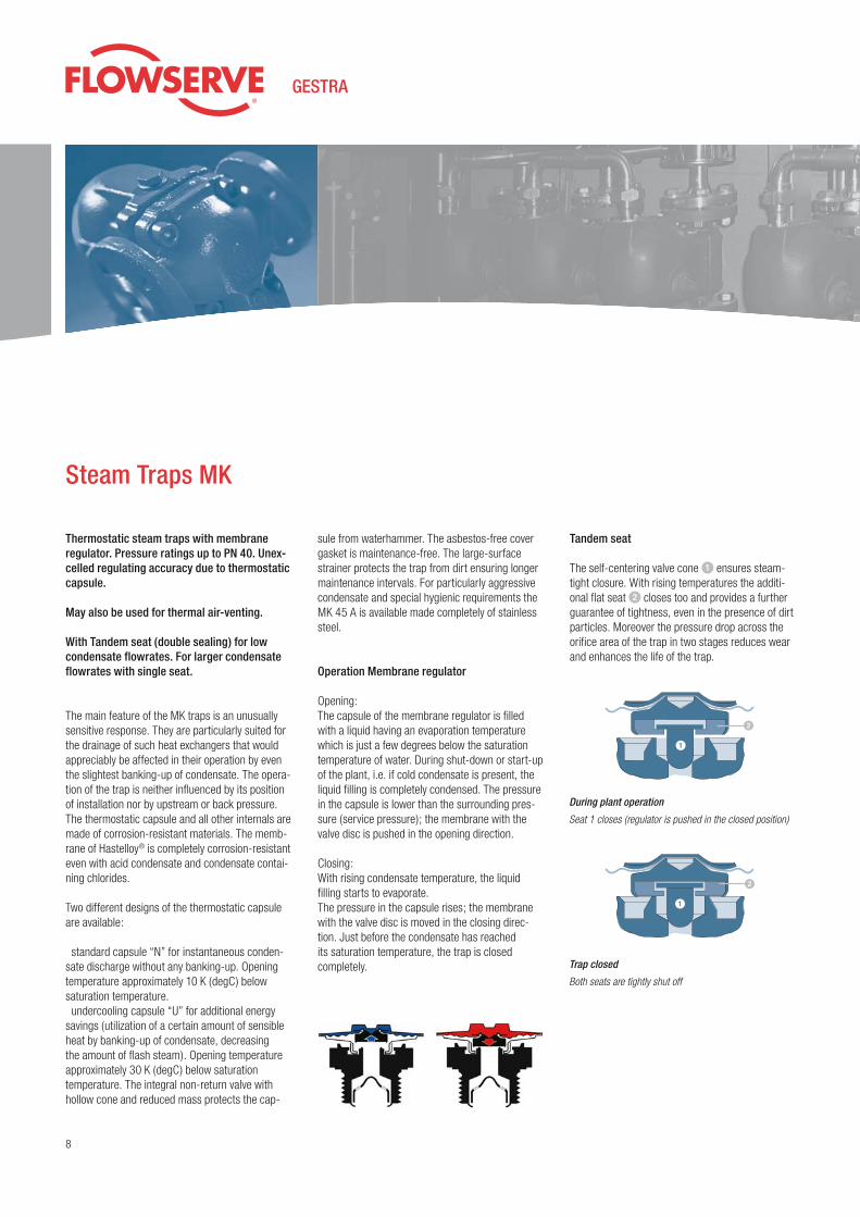
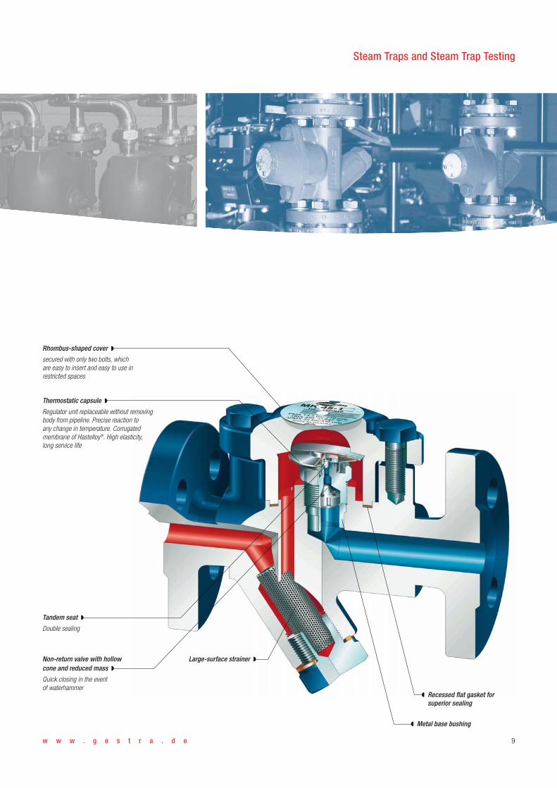
Tandem seat
The self-centering valve cone � ensures steam-tight closure. With rising temperatures the additi-onal flat seat � closes too and provides a further guarantee of tightness, even in the presence of dirt particles. Moreover the pressure drop across the orifice area of the trap in two stages reduces wear and enhances the life of the trap.
Steam Traps MK
Thermostatic steam traps with mem brane regulator. Pressure ratings up to PN 40. Unex-celled regulating accuracy due to thermostatic capsule.
May also be used for thermal air-venting.
With Tandem seat (double sealing) for low condensate flow rates. For larger conden sate flowrates with single seat.
The main feature of the MK traps is an unusually sensitive response. They are particularly suited for the drainage of such heat exchangers that would appreciably be affected in their operation by even the slightest banking-up of condensate. The opera-tion of the trap is neither influenced by its position of installation nor by upstream or back pressure. The thermostatic capsule and all other internals are made of corrosion-resistant materials. The memb-rane of Hastelloy® is completely corrosion-resistant even with acid condensate and condensate contai-ning chlorides.
Two different designs of the thermostatic capsule are available:
standard capsule “N” for instantaneous conden-sate discharge without any banking-up. Opening temperature approximately 10 K (degC) below saturation tempera ture. undercooling capsule “U” for additional energy
savings (utilization of a certain amount of sensible heat by banking-up of condensate, de creasing the amount of flash steam). Opening temperature approximately 30 K (degC) below saturation temperature. The integral non-return valve with hollow cone and reduced mass protects the cap-
During plant operation
Seat 1 closes (regulator is pushed in the closed position)
Trap closed
Both seats are tightly shut off
�
�
�
�
w w w . g e s t r a . d e 9
Tandem seat ◗
Double sealing
Large-surface strainer ◗Non-return valve with hollow cone and reduced mass ◗
Quick closing in the event of waterhammer
Thermostatic capsule ◗
Regulator unit replaceable without removing body from pipeline. Precise reaction to any change in temperature. Corrugated membrane of Hastelloy®. High elasticity, long service life
Rhombus-shaped cover ◗
secured with only two bolts, which are easy to insert and easy to use in restricted spaces
Metal base bushing◗
Recessed flat gasket for superior sealing
◗
Steam Traps and Steam Trap Testing
10
MK Types and Connections
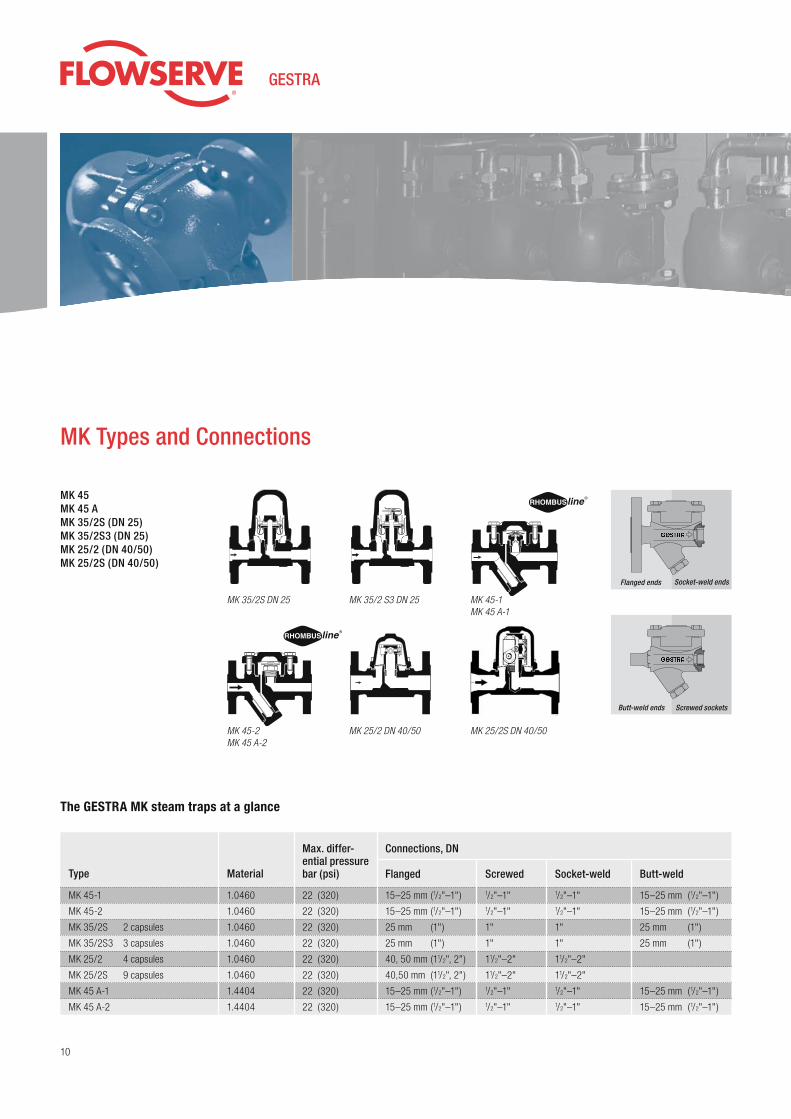
MK 45MK 45 AMK 35/2S (DN 25)MK 35/2S3 (DN 25)MK 25/2 (DN 40/50)MK 25/2S (DN 40/50)
The GESTRA MK steam traps at a glance
Type
MK 45-1
MK 45-2
MK 35/2S 2 capsules
MK 35/2S3 3 capsules
MK 25/2 4 capsules
MK 25/2S 9 capsules
MK 45 A-1
MK 45 A-2
Max. differ- ential pressurebar (psi)Material
Connections, DN
Flanged Screwed Socket-weld Butt-weld
1.0460
1.0460
1.0460
1.0460
1.0460
1.0460
1.4404
1.4404
22 (320)
22 (320)
22 (320)
22 (320)
22 (320)
22 (320)
22 (320)
22 (320)
15–25 mm (1/2"–1")
15–25 mm (1/2"–1")
25 mm (1")
25 mm (1")
40, 50 mm (11/2", 2")
40,50 mm (11/2", 2")
15–25 mm (1/2"–1")
15–25 mm (1/2"–1")
1/2"–1"1/2"–1"
1"
1"
11/2"–2"
11/2"–2"1/2"–1"1/2"–1"
1/2"–1"1/2"–1"
1"
1"
11/2"–2"
11/2"–2"1/2"–1"1/2"–1"
Socket-weld endsFlanged ends
MK 35/2S DN 25 MK 45-1MK 45 A-1
MK 35/2 S3 DN 25
MK 45-2MK 45 A-2
MK 25/2S DN 40/50
Screwed socketsButt-weld ends
MK 25/2 DN 40/50
15–25 mm (1/2"–1")
15–25 mm (1/2"–1")
25 mm (1")
25 mm (1")
15–25 mm (1/2"–1")
15–25 mm (1/2"–1")
w w w . g e s t r a . d e 11
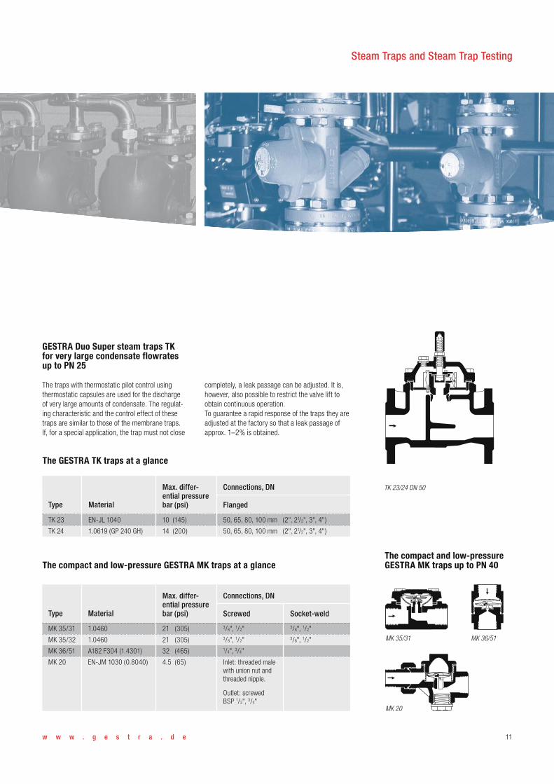
completely, a leak passage can be adjusted. It is, however, also possible to restrict the valve lift to obtain continuous operation.To guarantee a rapid response of the traps they are adjusted at the factory so that a leak passage of approx. 1–2% is obtained.
The compact and low-pressure GESTRA MK traps up to PN 40
GESTRA Duo Super steam traps TK for very large condensate flowrates up to PN 25
The traps with thermostatic pilot control using thermostatic capsules are used for the discharge of very large amounts of condensate. The regulat-ing characteristic and the control effect of these traps are similar to those of the membrane traps. If, for a special application, the trap must not close
The GESTRA TK traps at a glance
Type
TK 23
TK 24
Material Flanged
EN-JL 1040
1.0619 (GP 240 GH)
Max. differ- ential pressurebar (psi)
10 (145)
14 (200)
Connections, DN
50, 65, 80, 100 mm (2", 21/2", 3", 4")
50, 65, 80, 100 mm (2", 21/2", 3", 4")
MK 36/51MK 35/31
MK 20
The compact and low-pressure GESTRA MK traps at a glance
Type Material Screwed
Max. differ- ential pressurebar (psi)
Connections, DN
MK 35/31
MK 35/32
MK 36/51
MK 20
1.0460
1.0460
A182 F304 (1.4301)
EN-JM 1030 (0.8040)
Socket-weld
3/8", 1/2"3/8", 1/2"1/4", 3/4"
Inlet: threaded male with union nut and threaded nipple.
Outlet: screwedBSP 1/2", 3/4"
21 (305)
21 (305)
32 (465)
4.5 (65)
3/8", 1/2"3/8", 1/2"
TK 23/24 DN 50
Steam Traps and Steam Trap Testing

12
Ball Float Traps UNA
UNA 14 PN 25, UNA 16 PN 40compact trap for small condensate flowrates. Design “h” for horizontal and design “v” for vertical pipework. A conversion of “h” design to “v” design or vice versa is possible by repositioning body and control unit to suit the pipework layout.
UNA 23 PN 16, UNA 25 PN 40,UNA 26 PN 40For large condensate flowrates. Design “h” for horizontal and design “v” for vertical pipework.
For particularly aggressive fluids or special hygie-nic requirements the UNA 26 and UNA 15 are also available made completely of stainless steel.
UNA 27h PN 63For differential pressures up to 45 bar. Installation in horizontal pipework.
UNA 38 PN 100, UNA 39 PN 160Float trap controlled by the float, only for smaller flowrates.
UNA 38, 80 max. orifice, PN 100UNA 39, 140 max. orifice, PN 160 The trap operates with pilot control (with out auxili-ary power). It therefore dis charges large amounts of condensate at high pressures without requiring a large trap body.
UNA Special, PN 16–63 Float trap without pilot control for very large con-densate flowrates.
OperationPressure ratings up to PN 160For condensate discharge without banking-up even with load and pressure fluctuations
Ball fl oat traps are also suitable for the discharge of cold condensates, distillates and condensate derived from chemical products. They operate without any banking-up even with considerable load and pressure fl uctuations and at any back pressure.
Compared with other trap types, they are the least affected by dirt. The traps are supplied with “Duplex” control (thermostatic bellows for automatic air-venting), alternatively with “Simplex” control (without bellows) and hand vent valve. The control unit is easily accessible after removing the trap cover, and can be changed as a complete unit without removing the trap from the line.
The rolling ball valve produces very little friction and can be operated with a minimum of force. This results in small, light traps but with large capacities.
Air-venting when system is cold (start-up condition).
Air-venting during operation (temperature lower than standard steam temperature).
Discharge of boiling hot condensate (temperature equals saturation temperature).

w w w . g e s t r a . d e 13
Bolted cover ◗
Closed or sightglass cover (water-level indicator)
Upper plug ◗
Installation of manual vent valve or air balance possible
Thermostatic bellows ◗
for automatic air-venting (“Duplex” control). Without bellows (“Simplex” control) for cold fluids
Control unit ◗
Easy maintenance after opening cover. Complete unit may be changed without removing body from pipeline
Closing unit (orifice) ◗
A selection of orifice sizes for high and low pressure applications
Deflector ◗
guarantees the deflection of the condensate stream and reduces wear on the trap body
Rolling ball valve ◗
Low friction
Lower plug ◗
Draining of trap or for installation of lifting lever
Closed ball float ◗
Steam Traps and Steam Trap Testing

14
UNA Types and Connections
UNA 2...hUNA 2...v
UNA 27 h UNA 38
UNA 1...hUNA 1...v

w w w . g e s t r a . d e 15
UNA 39 UNA Special
UNA ball float traps at a glance
Type Material
Connections, DN
Flanged
UNA 14h / UNA 14v
UNA 16h / UNA 16v
UNA 16A h / UNA 16A v
Stainless steel
UNA 23h / UNA 23v
UNA 25h / UNA 25v
UNA 26h
UNA 26v
UNA 26h
Stainless steel
UNA 27
UNA 38h / UNA 38v
UNA 39
UNA Special
Body 1.0460 / Cover EN JS1049
Body 1.0460 / Cover 1.0619
Body 1.4404
Cover 1.4308
EN-JL1040
EN-JS1049
Body 1.0460
Cover 1.0619
1.4408
1.5419
Body 1.5415 / Cover 1.7357
1.7335
EN-JL1040, 1.0619, 1.5419
Screwed
1/2"–1"1/2"–1"1/2"–1"
1/2"–2"
1/2"–2"
Max. differ- ential pressurebar (psi)
13 (188)
22 (320)
22 (320)
13 (188)
32 (465)
32 (465)
32 (465)
45 (650)
80 (1160)
140 (2030)
16–45 (232–650)
Butt-weld
15–25 mm (1/2"–1")
15–50 mm (1/2"–2")
15–50 mm (1/2"–2")
25, 40, 50 mm (1", 11/2", 2")
15–50 mm (1/2"–2")
15, 25, 50 mm (1/2", 1", 2")
Socket-weld
1/2"–1"
1/2"–2"
1/2"–2"
1", 11/2", 2" 1/2"–2"
15–25 mm (1/2"–1")
15–25 mm (1/2"–1")
15–25 mm (1/2"–1")
15–50 mm (1/2"–2")
15–50 mm (1/2"–2")
15–50 mm (1/2"–2")
15–50 mm (1/2"–2")
25, 40, 50 mm (1", 11/2", 2")
15–50 mm (1/2"–2")
15, 25, 50 mm (1/2", 1", 2")
50–100 mm (2"–4")
Steam Traps and Steam Trap Testing

16
Compact, maintenance-free steam trap of stainless steel for use with a universal swivel connector.
The main area of application is the drainage of steam lines and tracing systems. The functional unit is mounted to the universal connector by mean of two hexagon screws (sup-plied together with the connector). With connectors already installed in the plant, the existing screws can be used.
Steam Traps ECONOline
The ECONOline steam trap is available with three different time-tested functional units:
BK 36A/7 Functional unit „thermostatic bimetallic“ with corrosion-resistant Duo stainlesssteel regulator unaffected by waterhammer, for automatic venting and drainage practically without any banking-up.
MK 36A/7 Functional unit „thermostatic capsule“ with corrosion-resistant membrane regulator 5N1 that is unaffected by wa ter-hammer, for automatic venting and drainage practically without any banking-up.
DK 36A/7 Functional unit „thermodyna-mic“ for drainage practically without any banking-up.
Your benefits at a glance
• Mounting in any positione• Integrated gaskets for connector fitting• Rapid installation, thanks to 2-screw mounting• All functional units can be supplied with a universal connector as an option (separate component)
The ECONOline steam traps at a glance
Type
BK 36A/7
MK 36A/7
DK 36A/7
Max. differential pressure bar (psi)Material
Connections, universal connector, size (DN)
Screwed Socket-weld Butt-weld
1.4408
1.4408
1.4408
29 (420)
29 (420)
29 (420)
1/2"–1"1/2"–1"1/2"–1"
1/2"–1"1/2"–1"1/2"–1"
1/2"–1"1/2"–1"1/2"–1"
Functional unit at anexisting universal connector
Universalconnector UCY

w w w . g e s t r a . d e 17
Automatic drain valve for rapid condensate dis-charge during the start-up of steam plants and for draining the remaining condensate at shut-down. The formation of a vacuum and possible frost da-mage are prevented. To avoid freezing of the AK, the drain line should be kept as short as possible and the valve be included in the thermal insulation. The valve is controlled only by the pressure. It re-places a manually operated by-pass valve.
Draining a steam line at start-up
At start-up of the steam line the pressure in the line is initally zero, although steam is already con-densing. However, the condensate formed cannot be discharged by the steam trap into the rising condensate line, as there is not yet any differential pressure available to lift the condensate. In this case, in the past a by-pass valve mounted at the lowest point of the system had to be openend by hand, so that the condensate could drain freely. As shown in the schematic representation, the drain valve AK 45 ensures automatic condensate discharge until the pressure in the steam line has reached 0.8 bar (11.6 psi) (factory-set closing
pressure). This pressure in the steam line is suffici-ent for the steam trap to discharge the condensate into the condensate-return line.
At this pressure the AK 45 closes instantaneously and automatically. When the steam system is shut down, the pressure in the steam line drops slowly. As soon as the pressure has dropped below 0.8 bar, the AK 45 opens, discharges the remaining condensate and prevents the formation of vacuum.
Condensate drain valve AKPressure ratings up to PN 40
Steam ◗
AK 45
Condensat
The AK condensate drain valve at a glance
Type Material Flanged
Max. differ- ential pressurebar (psi)
0.8 (11.6)
Connections, DN
AK 45 1.0460
Screwed
1/2"–1"15–25 mm (1/2"–1")
Other Traps for Special Applications
Steam Traps and Steam Trap Testing

18
Other Traps for Special Applications
Pressure rating PN 40
The UBK 46 is a special version of the BK range of traps designed to save energy by holding back the condensate until it has cooled down to the adjus-table discharge temperature, thus permitting the utiliza tion of the sensible heat of the condensate
and avoiding flash steam. The Duo stainless steel thermostat is corrosion-resistant and unaffected by waterhammer. Installation in any position.
With large-surface Y-type strainer: Main field of application: steam heated tracing systems.
The UBK trap at a glance
Type Material Flanged
Max. differ- ential pressurebar (psi)
32 (465)
Connections, DN
UBK 46 1.0460
Screwed
1/2"–1"15–25 mm (1/2"–1")
Socket-weld
1/2"–1"
The SMK trap at a glance
Type Material Butt-weld ends
Max. differ- ential pressurebar (psi)
6 (87)
Connections, DN
SMK 22 1.4435
Clamp
3/8", 1/2", 3/4", 1"
Screwed
Steam trap UBK 46
SMK 22 Pressure rating PN 10
The thermostatic steam trap features minimum stagnant area and a corrosion-resistant membrane regulator unaffected by waterhammer. Used for discharging of condensate and air venting of steam in sterile and aseptic applications.
The membrane regula tor features a self-centering valve cone that can move freely, thereby ensuring steamtight shut-off unaffected by particulate mat-
ter. High sensitivi ty thanks to reduced dimensions of the regulator (evaporation thermostat). Automa-tic air-venting and discharge of condensate without any banking-up within the rated pressure/ tempe-rature range. The opening temperature is approx. 5 K below the boiling point. All parts in contact with the fluid are made of stainless steel and the body gasket is of EPDM (O-ring) in accordance with the regulations speci fied by the Food and Drug Adminis tra tion (FDA). The surface roughness Ra of the wetted surfaces is ≤ 0.8 µm.

w w w . g e s t r a . d e 19
The liquid drainer at a glance
Type Material Flanged
Max. differentialpressure bar (psi)(density 1 kg/dm3)
16 (130)
Connections, DN
UNA 14 P, h+v EN-JL1040
Screwed
1/2", 3/4", 1"15, 20, 25 mm (1/2"–1")
UNA 14 P
Air or gas line ◗
Collectingpocket ◗
with or without valve;valve spindle horizontal
Air-balance pipe
Float trap for hori-zontal installation
◗
◗
Liquid drainer for compressed-air and gas systems PN 25
For continuous draining of gas and compressed-air systems, float traps with “Simplex” control units (i.e. without thermostatic air vent) are used.
To ensure perfect drainage, the air traps can be fit-ted with a balance pipe which allows air in the trap body to escape so that it cannot obstruct the flow of condensate into the trap. A balance pipe is not necessary if the trap is installed directly below the equip ment to be drained and if the drain line runs vertically. In this instance the pipe leading to the trap should be of sufficient size so that any air can
escape by bubb ling through the condensate. All air traps are equipped with a plug allowing a balance line to be connected, and are fitted with a float lifting lever to facilitate manual purging of the valve area. UNA traps are fitted with a perbunan rubber valve ball to provide tight closure; a stainless steel valve ball may be specified for higher temperatures and pres sures.
In the case of very small conden sate flowrates the tightness of the valve closure should be con-sidered.
Steam Traps and Steam Trap Testing

20
Pressure ratings up to PN 40
The GESTRA VAPOSCOPE allows visual supervi-sion of flow conditions in pipelines. These double-sided sightglasses can be used for checking heat exchangers and condensate systems, so that disturbances are immediately recognized and loss of production avoided.
Operation
As the specific gravity of gaseous media (steam) is lower than that of liquids (conden sate), the steam will pass over the condensate. This fact is used in the VAPOSCOPE to distin guish between steam and conden sate. Condensate, steam and air are directed by a rigid deflector through the water seal
formed by the condensate in the VAPOSCOPE. Steam and gas pass over the condensate and depress the con densate level. The following condi-tions can be observed in the sightglass.
Steam Trap Testing
VAPOSKOP VK
Sightglass
Steam or air passing through the VAPOSCOPE depress the level of the condensate below the deflector. The steam which is invisible fills the space between deflector and water level. A mixture of water and steam may lead to a strong formation of bubbles together with turbulence. Possible cau-ses for live steam loss: Contamination or failure of steam traps.
The VAPOSCOPE is completely flooded. If the VAPOSCOPE is installed immediately downstream of the heat exchanger it is to be expected that the condensate is banking up into the heat exchanger. Possible causes for banking-up of condensate: Start-up of plant, heat exchanger operates with additional undercooling, changed operating con-ditions (e.g. extremely high heat consumption), steam trap size not sufficient, blockage or failure of steam trap.
Perfect operation of steam trap and heating sur-face. The deflector is im mersed in the water level. The formation of small bubbles or a slight turbu-lence are effects that can be ignored.
Loss of live steam Banking-up of condensateNormal service condition

w w w . g e s t r a . d e 21
Test set VKE
Test set for monitoring steam traps Pressure ratings up to PN 40
The test set VKE is used for monitoring steam traps to detect the leakage of live steam and the ban-king-up of condensate. A separate test chamber fitted with measuring electrode is installed directly upstream of the steam trap to be monitored. The electrode is then linked either to the remote test unit or to the handheld test unit. The VKE test system with test chamber can be used for steam traps of all types and makes.
Operation
The electrode signals the states “condensate” or “steam” to the test unit NRA 1-3 (automatic remote monitoring) or to the handheld test unit (measuring in situ). If the steam trap operates correctly, cond-ensate flows around the electrode. In the case of
Handheldtest unit
VK and VKE at a glance
Type Material
Connections, DN
Flanged Screwed Socket-weld
VK 14
VK 16
VKE 16 (with test chamber)
VKE 16 A (with test chamber)
VKE 26 (with test chamber)
EN-JL1040
1.0460
1.0619
1.4571
1.0460
15–50 mm (1/2"–2")
15–50 mm (1/2"–2")
15–50 mm (1/2"–2")
15–50 mm (1/2"–2")
1/2"–2"1/2"–2"
3/8"
1/2"–2"
steam losses across the trap, the condensate is displaced until the electrode is surrounded by steam. The condition is indicated accordingly. The test unit NRA 1-3 has channels for up to 16steam traps. Each of the connected steam traps can be monitored for live steam losses and ban-king-up of condensate. Through various modes and inclusion of the plant temperature, the limit values are adapted automatically and faults are detected instantaneously. The maintenance interval is signalled on the front panel of the test unit, and a potential-free relay contact is used for signalling an alarm condition. The test unit is supplied in a case for wall mounting or a case for panel mounting.The VKE 26 test chamber is used for reliable monitoring of the installation for banking-up of condensate.
Remote test unit NRA 1-3
Steam Traps and Steam Trap Testing

22
Steam Trap Testing Units
VAPOPHONE ultrasonic detector VKP 10
The portable ultrasonic detector is specially desi-gned for detecting steam loss through steam traps and stop valves.Live steam leakage is detected by sound in the ultrasonic range caused by flowing steam. The mechanical ultrasonic vibrations are detected by the probe and converted into electric signals which are amplified in the measuring instrument and indi-cated on a meter.The VKP 10 must not be used in potentially explo-sive areas. Degree of protection IP 41.
TRAPtest VKP 40 / VKP 40Ex
Faulty steam traps are a major source of waste in a steam distribution system. A trap that is blowing live steam is the worst offender and the decreased efficiency results in lost production.
Systematically checking steam traps for loss of live steam and consequent heat loss is therefore a matter of prime importance. This is easy to do with all types and makes of steam traps by using GESTRA’s steam trap monitoring, recording and evaluation system VKP 40 / VKP 40Ex, which de-tects and assesses ultrasonic vibrations transmit-ted through the trap body by live steam flowing through the trap. The visual display of the terminal shows all signals received during the test in the form of a graph, clearly distinguishing between a trap working correctly and one passing even very small amounts of steam.As part of the test procedure, the temperature prevailing at the steam trap is also recorded. In conjunction with specified service pressures, this makes it possible for the system to identify steam
traps which are obstructed (causing the conden-sate to bank up).All test results obtained by the hand-held terminal can be stored, evaluated and organized on the PC. The TRAPtest VKP 40 / VKP 40Ex consists of themeasuring transducer VKPS 40, the portable ter- minal VKPN 40 / VKPN 40Ex and the correspon-ding software for data management by PC.
It is well known that steam losses through trap fai-lure, dirt in the steam trap, wrong use of traps or incorrectly installed equipment can easily waste thousands of euros a year. An optimized steam system is therefore essential and can even nowa-days save up to 30% of the energy capacity. Call us in for a full mechanical and electrical service inspection of your steam and condensate system – our team of engineers are on hand to keep your installation working at peak efficiency, to maximise your maintenance budget and optimise the overall plant efficiency.
Hand-held terminal VKPN 40Exfor use in potentially explosive areas◗ Approval BVS 04 ATEX E 149◗ CE 0158 Ex II 2G EEX ib IIC T4
Monitoring, recording and evalua tion system TRAPtest VKP 40 (or VKP 40Ex) for checking all makes and types of steam traps for steam losses and banking-up of condensate.

w w w . g e s t r a . d e 23
Further Valves Suitable for Condensate Discharge
ZK 29BA 46GK 11, 21
GK Super steam trap
Steam trap with stage nozzle for dischargingvery large condensate flowrates. With integrated VAPOSCOPE for optimum trap adjustment.
Regulating steam trap:Continuous blowdown valve BA 46 Pressure ratings up to PN 40
The valve can also be used as thermodynamic steam trap with stage nozzle (without sampling valve).
Control valves ZK with radialstage nozzle Pressure ratings up to PN 630
The valve can also be used for injection-cooling, level and leak-off control, as well as for drainage duties.
BK 45 with integratedtemperature sensor
Innovations in Steam Trap Technology
RHOMBUSline with new possibilities
Available on request for the RHOMBUSline steam traps BK 45, BK 46, MK 45 and UBK 46:
◗ Integrated measuring probe for monitoring the system for live steam losses and (in con - junction with a handheld test unit or test unit NRA 1-3). Without strainer.
◗ Integrated temperature measurement (PT-100 element with terminal box), for monitoring against banking-up. With strainer.
Steam Traps and Steam Trap Testing

GESTRA AGMünchener Str. 77, D-28215 BremenP.O. Box 10 54 60, D-28054 BremenTelephone +49 (0) 421-35 03-0Telefax +49 (0) 421-35 03-393E-mail [email protected] www.gestra.de
810124-04/806 EMA · © 2006 · GESTRA AG · Bremen · Printed in Germany With Energy into the Future