Standard Releasing Spear
Manual B215

RELEASINg SPEAR STOP Sub ASSEMbLY
OVERVIEWThe Logan Releasing Spear Stop Sub Assembly is an accessory designed to convert a releasing spear with a flush-type mandrel into a shouldered type spear. It is installed in the box connec-tion at the top of the mandrel when the use of a positive stop is desired or required.
A stop ring can be added to increase shoulder diameter. All stop rings are furnished with left-hand threads.
When ordering, please specify:(1) O.D. of Stop Sub (2) Length from stop to threaded connection (3) Top and bottom connection desired (4) Assembly number of spear on which the stop sub will be run (5) O.D. of Stop Ring
STANDARD STOP SUB & FLUSH MANDREL OD 3-1/8 3-1/4 3-5/8 4-1/32 5STOP SUB ASSEMBLY Logan Part No. 400-064 400-063 400-050 400-051 400-052STOP SUB (2 PCS. REQ’D)UPPER SECTION 18" LENGTH Logan Part No. F110002-A F110005-A F11000-A F11001-A F11002-ALOWER SECTION 12" LENGTH Logan Part No. F110002-B F110005-B F11000-B F11001-B F11002-BSTOP RING Logan Part No. F120002 F120005 F12000 F12001 F12002
Minimum O.D. 4-1/8 4-1/8 4-1/2 5 6
STANDARD STOP SUB & FLUSH MANDREL O.D. 5-3/4 7-1/4 7-3/4 8-1/4 11-3/4STOP SUB ASSEMBLY Logan Part No. 400-053 400-054 400-062 400-065 400-056STOP SUB (2 PCS. REQ’D)UPPER SECTION 18" LENGTH Logan Part No. F11003-A F11004-A F11005-A F11015-A F11006-ALOWER SECTION 12" LENGTH Logan Part No. F11003-B F11004-B F11005-B F11015-B F11006-BSTOP RING Logan Part No. F12003 F12004 F12005 F12015 F12006
Minimum O.D. 7 8-5/8 9-5/8 9-5/8 13-3/8
Logan Oil Tools reserves the right to change or discontinue designs without notice.
Top Section
Stop Ring
Bottom Section
Logan Releasing Spear Stop Sub Assembly • 33
NOTES
Logan Standard Releasing Spear
Page 1 • Standard Releasing Spear • Manual B215
Logan St andard Releas ing Spear • 1
Cont ent s
Standard Releasing SpearOverview................................................................................ 2Use ........................................................................................ 2Construction .......................................................................... 2Illustrations
Spear Assembly with Flush-Type Mandrel......................... 3Spear Assembly with Shoulder-Type Mandrel ................... 3Optional Nuts ..................................................................... 3
Operation............................................................................... 2Precautions........................................................................ 2Internal Cutting................................................................... 4Engaging a Fish................................................................. 4Releasing a Fish ................................................................ 4
Assembly ............................................................................... 4Assembly of Releasing Spear............................................ 4Assembly of Spear Pack-off............................................... 4
Maintenance.......................................................................... 4Disassembly of Releasing Spear ....................................... 5Disassembly of Spear Pack-off.......................................... 5
Principal Dimensions....................................................... 6 – 7Complete Assemblies and Parts Lists ............................8 – 11Recommended Tightening Torques..................................... 12Releasing Spear Grapple Range Charts ..................... 15 – 23Calculated Strengths ................................................... 24 – 28
Segmented Spear Grapple AssemblyIllustration ............................................................................ 13Complete Assemblies and Parts Lists ......................... 13 – 14
Releasing Spear Pack-off AssemblyAssembly ............................................................................... 4Maintenance.......................................................................... 4
Disassembly....................................................................... 5Illustration .............................................................................. 5Replacement Packing Cups and Thimbles.................. 29 – 32
Releasing Spear Stop Sub AssemblyIllustration ............................................................................ 33Complete Assemblies and Parts Lists ................................. 33
LEGAL NOTICEAll references to Bowen® part numbers in this literature are used to identify interchangeable tools and parts. Reference to such tools and parts does not imply that Logan Oil Tools is a licensee or is in any way affiliated with National Oilwell Varco.Logan Oil Tools does not sell, or offer to sell, National Oilwell Varco (Bowen) products.
“Bowen” is a registered trademark of National Oilwell Varco.
2nd Printing, August 2012. Rev. 1

Manual B215 • Standard Releasing Spear • Page 2
2 • Logan St andard Releas ing Spear
OVERVIEW
Logan Standard Releasing Spears provide a positive means to internally engage and retrieve a fish from the well. The design of this rugged, dependable, and inexpensive internal catch fishing tool ensures positive engagement, easy release, and re-engagement.
USE
The Logan Standard Releasing Spear can engage and retrieve tubing, cas-ing, and drill pipe of all sizes. It may be used with other equipment such as spear pack-off assemblies and internal cutters.
CONSTRUCTION
The Logan Standard Releasing Spear consists of a mandrel, grapple, releas-ing ring, and a bull nose nut. The size and type of the upper box connection is furnished according to customer specification.
MandrelThe mandrel type may be specified as either flush or shoulder. Flush-type mandrels are designed to completely enter the fish. Shoulder-type mandrels provide a positive landing position on top of the fish. The mandrel is made of high strength, specially heat-treated alloy steel. The lower end is threaded to accept a bull nose nut, or the optional sub, mill, and sidehill type nuts.
Standard Spear GrappleOne-piece spear grapples are designed and manufactured to engage a specific size and weight of tubing, casing, or drill pipe to ensure maximum surface engagement and minimum fish distor-tion.
Segment-Type Spear GrappleThe segment-type spear grapple enhances the spear’s usefulness by providing an extended catching range
beyond the maximum range of the standard one-piece grapple. The Logan Segment-Type Spear Grapple consists of a grapple body, eight grapple seg-ments, two retainer rings, four retainer ring screws, six retainer ring spacers, and sixteen grapple segment screws. Refer to the illustration on page 12.
Release RingThe cammed release ring matches the cammed nut ensuring a positive locking device that will not freeze or jam. It isa standard component of the releasing spear.
NutThe standard bottom nut is a bull nose nut. Optional nut types — sub, mill, and sidehill — are available. Refer to the illustrations on page 3.
When other tools, such as a spear pack-off assembly or internal cutters, will be utilized below the releasing spear, the sub type nut replaces the standard bull nose nut to provide the required connection.
The mill type nut mills away jagged ends of a fish to ensure entry into the fish. It can also effectively drill out sand from a plugged fish.
A sidehill type nut is used to align the Releasing Spear with a fish that is im-bedded in the side wall of the hole.
Heavy Duty Releasing SpearsLogan Heavy Duty Releasing Spears (assemblies designated as “HD” in the parts lists) are used in situations where a swelling of the fish presents a prob-lem. These assemblies have relatively longer mandrels and grapples than standard (STD) spears resulting in more supported wickered area to engage the fish. The longer mandrel and grap-ple distribute the swelling forces over a greater area, thereby substantially reducing those forces.
Heavy Duty Releasing Spears are less prone to damage from swelling of the fish and are actually stronger than a Standard Releasing Spear even though the tensile strength of the mandrels are the same.
Stop Sub AssemblyThe Logan Releasing Spear Stop Sub Assembly is an accessory designed to convert a releasing spear with a flush-type mandrel into a shouldered type spear. It is installed in the box con-nection at the top of the mandrel when the use of a positive stop is desired or required.
A stop ring can be added to increase shoulder diameter. All stop rings are furnished with left-hand threads. Seepage 32 for more information.
Spear Pack-off AssemblyPack-off assemblies are available for all Logan Standard Releasing Spear As-semblies and are designed to efficiently pack off all sizes of drill pipe, tubing and casing. Circulation through the fish is enabled by attaching the Spear Pack-off Assembly to the bottom of the spear with a sub type nut. See pages 28 – 31 for more information.
OPERATION
PrecautionsAlways maintain a moderate upward strain on the fishing string when rotating either to the left or right during oper-ation.
It may be necessary to rotate the fish-ing string more than a full turn to setor release the Releasing Spear in deep or crooked holes. Additional moderate rotation does not harm the Releasing Spear or the operation.
Always bump down the full weight of the fishing string before beginning the releasing operation.

Page 3 • Standard Releasing Spear • Manual B215 Logan St andard Releas ing Spear • 3
Flush-Type Mandrel
Spear Grapple
Release Ring
Bull Nose Nut
Spear Assembly with Flush Type Mandrel
Spear Assembly with Shoulder Type Mandrel
SidehillType Nut
MillType Nut
SubType Nut
Optional Nuts
Shoulder-Type Mandrel
Spear Grapple
Release Ring
Bull Nose Nut

Manual B215 • Standard Releasing Spear • Page 4
Thoroughly clean and lubricate parts. If the tool will be stored for a long period, paint or lubricate the exterior surfaces to prevent corrosion.
Refer to the illustration on page 3 andproceed with assembly as follows:
1. Clamp the Releasing Spear horizon-tally into a suitable vise, securing the upper mandrel joint end.
CAUTION: Use only enough grip-ping action in the vise to break the connections. Avoid making heavy tool marks.
2. Heavily grease the helix of the mandrel.
3. Install the spear grapple on the lower pin end of the mandrel, screw-
ing it on with left-hand (counter- clockwise) rotation. Grease the
interior of the grapple if it is large.
4. Slip the release ring onto the man- drel with the cams facing downward towards the nut.
5. Apply thread dope or lubricant to the threads on the lower end of the mandrel. Install the nut and tighten.
6. Screw the grapple down the helix until it rests against the release ringand nut. Hand tighten.
7. Paint or lubricate exterior surfaces to prevent corrosion.
8. Tighten all connections to the rec- ommended torque before running the Standard Releasing Spear in the hole. Refer to the Recommended Tightening Torque tables on page 12.
Assembly is now complete and the tool is ready for service.
Assembly of Spear Pack-offRefer to the illustration on page 5 and proceed with assembly as follows:
1. Clamp the assembly horizontally intoa suitable vise, securing the lower end of the pack-off mandrel.
CAUTION: Use only enough grip-ping action in the vise to break the connections. Avoid making heavy tool marks.
2. Slide the stabilizer onto the mandrel.
3. Slide the packing cup onto the mandrel with the large open end facing downward. Make sure it is seated properly on the mandrel shoulder.
4. Slide the thimble onto the mandrel and onto the packing cup. Force it down tightly around the upper end of the packing cup.
5. Apply thread dope or grease to the mandrel threads. Install the adapter sub onto the mandrel and tighten.
6. Paint or lubricate the exterior metal surfaces of the assembly.
NOTE: Do not paint or lubricate the packing cup. Paint, sunlight, sol-vents, and most lubricants are harm-ful to rubber products.
Assembly is now complete.
MAINTENANCE
Maintenance of the Standard Releasing Spear and Spear Pack-off Assembly is simple, but important.
After each use, the tools should be completely disassembled, thoroughly inspected, and repaired as required.
Before reassembling, inspect all parts, especially the grapple. Check the wick-ers for damage and wear to ensure safe operation. Clean and lubricate parts as they are reassembled. Grease or paint the exterior to prevent corrosion.
Examine the packing cup of the Releas-ing Spear Pack-off Assembly for wear or damage. Replace the packing cup if necessary. (Refer to pages 29 – 32 for packing cup and thimble part numbers.)
Internal CuttingWhen running an internal cutter below the releasing Spear, replace the bull-nose nut with a sub type nut. Pipe between the internal cutter and Releas-ing Spear enables the Spear to remain above the fish during the cutting oper-ation. The Spear is lowered into the cut-off section to retrieve it after the cut has been completed.
Engaging a FishThe Logan Releasing Spear is made up to the bottom of the fishing string and lowered to the desired depth into the fish. Rotate the mandrel one full rotation to the left to turn the mandrel through the spear grapple and move the spear grapple into engaging position. Pulling straight up will cause the tapers on the mandrel to expand the spear grapple and allow it to positively engage the fish.
Releasing a FishTo release the fish, bump down and make two to three rotations to the right. This right-hand rotation allows the man-drel to move up through the spear grap-ple thereby placing the spear grapple against the release ring and putting the spear in release position. Combined right-hand rotation with straight upward pull will release the spear from the fish. Continue with slow, right-hand rotation until the Releasing Spear is clear of the fish.
ASSEMBLY
Assembly of Releasing SpearThe Logan Standard Releasing Spear can easily be assembled at the rig site where it will be used.
Check all parts to ensure that they are in good working condition before beginning assembly. Make sure the Releasing Spear is the proper size for the operation. (Refer to the Releasing Spear Grapple Range Charts on pages 15 – 23.)
4 • Logan St andard Releas ing Spear

Page 5 • Standard Releasing Spear • Manual B215
Logan St andard Releas ing Spear • 5
NOTE: Do not paint or lubricate the packing cup. Paint, sunlight, solvents, and most lubricants are harmful to rubber products.
Disassembly of Releasing SpearRefer to the illustration at right and proceed with disassembly as follows:
1. Clamp the Releasing Spear horizon-tally into a suitable vise and secure the upper mandrel joint end.
CAUTION: Use only enough grip-ping action in the vise to break the connections. Avoid making heavy tool marks.
2. Loosen and remove the nut or spear pack-off-assembly.
3. Slide the release ring from the mandrel.
4. Remove the spear grapple by screwing it down the helix with right-
hand (clockwise) rotation.
Disassembly is now complete.
Disassembly of Spear Pack-offRefer to illustration at right and proceed with disassembly as follows:
1. Clamp the assembly horizontally intoa suitable vise and secure the lower end of the pack-off mandrel.
CAUTION: Use only enough grip-ping action in the vise to break the connections. Avoid making heavy tool marks.
2. Loosen and remove the adapter sub.
3. Slide off the thimble.
4. Remove the packing cup.
5. Remove the stabilizer.
Disassembly is now complete.
Adapter Sub
Thimble
Packing Cup
Stabilizer (remov-able)
Pack-off Mandrel
Logan Releasing Spear Pack-off Assembly

Manual B215 • Standard Releasing Spear • Page 6
6 • Logan St andard Releas ing Spears Pr inc ipa l Dim ensions
B C E G
A
J
H
I
F
STANDARD RELEASING SPEARS PRINCIPAL DIMENSIONS
Notes:1) For Flush or Shoulder type, specify O.D. of shoulder, “A”2) Mandrel length desired, “C”
SHOULDER TYPE
SPEAR SHOULDER FLUSHTYPE ONLY TYPE ONLY
MANDREL SPEAR SIZE CLASS ID A B C D EF1000 1.050 OD Pipe Standard … 1-1/2 4-1/8 6 … 2-3/8F1001 1.313 OD Pipe Standard … 1-5/8 3 3 … 3-5/16F1002 1.660 OD Tubing Standard … 1-13/16 3 3 3-25/32 3-5/16F1004 1.900 OD Tubing Standard … 2-1/2 5 3 7 5-1/16F1005 2-3/8 OD Drill Pipe Standard … 3-1/8 7 3 7 5-29/32F1007 2-3/8 OD Tubing Standard 3/8 3-1/8 7 3 7 6-3/4F1008 2-3/8 OD Tubing Standard 3/8 3-1/8 7 3 7 9F1009 2-7/8 OD Tubing Standard 3/8 3-3/4 7 3 7-1/4 6-3/4F1010 2-7/8 OD Tubing Heavy Duty 3/8 3-3/4 7 3 7-1/4 9F1012 3-1/2 OD Tubing Standard 1/2 3-3/4 7 3-1/2 10-1/2 12F1013 3-1/2 OD Drill Pipe Heavy Duty 1/2 3-3/8 7 3-1/2 10-1/2 9-3/4F1014 4 OD Tubing Light Duty 3/4 3-3/4 7-1/2 3 10-3/8 8-1/8F1015 4 OD Tubing Standard 3/4 4-1/8 7-1/2 3 10-1/2 12F1016 4-1/2 OD Tubing Light Duty 3/4 4-1/2 8 3-1/2 3-3/4 9-3/4F1017 4-1/2 OD Tubing Standard 3/4 4-1/2 8 3-1/2 9-1/2 14-1/4F1018 5 OD Casing Light Duty 7/8 4-3/8 8 3-1/2 9-1/2 9-3/4F1019 5 OD Casing Standard 7/8 5 8 3-1/2 12 14-1/4F1022 6 OD Casing Light Duty 1 6 8 5-1/2 12 13F1023 6 OD Casing Standard 1 6 8 5-1/2 12 13F1024 7 OD Casing Standard 2 7 10 6-1/2 16-1/2 14-5/8F1026 7 OD Casing Heavy Duty 2 7 10 6-1/2 13-1/2 21-3/8F1029 8-5/8 OD Casing Standard 2-3/4 8-5/8 14 7 20-7/8 14-5/8F1030 8-5/8 OD Casing Heavy Duty 2-3/4 8-5/8 … … 20-7/8 21-3/8F1032 9-5/8 OD Casing Standard 2-13/16 9-5/8 15-3/8 7 20-7/8 14-5/8F1034 9-5/8 OD Casing Standard 2-13/16 9-5/8 … … 20-7/8 21-3/8F1035 13-3/8 OD Casing Standard 3-1/2 13-3/8 17-7/8 7 22-3/8 16-7/8
Logan Oil Tools reserves the right to change or discontinue designs without notice.

Page 7 • Standard Releasing Spear • Manual B215
Logan St andard Releas ing Spears Pr inc ipa l Dim ensions • 7
L
D E G
H
K
H
M F
SPEAR SHOULDER FLUSH TYPE ONLY TYPE ONLY
MANDREL F G H I J K L MF1000 7/8 2-3/8 11/16 9-5/8 15-1/4 … … 3/16F1001 1-3/8 2-1/2 15/16 7-11/16 11-13/16 … … 1/4F1002 1-3/8 2-1/2 1-1/8 7-11/16 11-13/16 … … 3/8F1004 2-1/4 5-5/8 1-3/8 10-5/16 18-11/16 … … 7/16F1005 2-1/4 6-17/32 1-11/16 … … 19-7/16 … 5/8F1007 2-1/4 6-5/8 1-7/8 12 23-3/8 23-3/8 … 5/8F1008 2-1/4 6-5/8 1-7/8 14-1/4 25-5/8 22-5/8 … 5/8F1009 2-1/2 7 2-5/16 12-1/4 23-3/4 21 … 5/8F1010 2-1/2 7 2-5/16 14-1/2 26 23-1/4 … 5/8F1012 3-1/2 9 2-13/16 19 31-1/2 32-1/2 … 5/8F1013 3-5/8 8-1/8 2-1/2 16-5/8 31-1/8 … … 5/8F1014 2-1/2 8 3-1/4 13-5/8 26-5/8 26-1/2 … 5/8F1015 3-1/2 9 3-1/4 18-1/2 31-1/2 31-1/2 … 5/8F1016 3-1/2 10-3/4 3-5/8 16-3/4 32 32 … 1F1017 3-1/2 10 3-5/8 21-1/4 35-3/4 33-3/4 … 3/4F1018 3-1/2 10-5/8 4-1/32 16-3/4 31-7/8 29-7/8 … 13/16F1019 3-1/2 10-5/8 4-1/32 21-1/4 36-3/8 36-7/8 … 13/16F1022 3-1/2 12 5 16-3/8 39-3/16 37-11/16 3-5/16 1-1/4F1023 3-1/2 12 5 16-3/8 … 43 3-5/16 1-1/4F1024 3-1/2 12-3/4 5-11/16 … … 40-1/4 3-1/2 1-5/8F1026 3-1/2 12-3/4 5-11/16 31-3/8 53-3/8 47 3-1/2 1-5/8F1029 4-1/2 13-3/4 7-1/4 26-1/8 53-7/8 49-1/4 5 1-5/8F1030 4-1/2 13-3/4 7-1/4 … … 56 5-3/4 1-5/8F1032 3-1/2 14 8-1/4 25-1/8 51 49-1/4 6-1/4 1-5/8F1034 3-1/2 13-3/4 8-1/4 … … 56 6-1/4 1-5/8F1035 3-1/2 12 11-3/4 27-3/8 53-3/4 51-1/4 7-3/4 1-5/8
Logan Oil Tools reserves the right to change or discontinue designs without notice.
Notes:1) For Flush or Shoulder type, specify O.D. of shoulder, “A”2) Mandrel length desired, “C”
FLUSH TYPE
STANDARD RELEASING SPEARS PRINCIPAL DIMENSIONS

Manual B215 • Standard Releasing Spear • Page 8
8 • Logan St andard Releas ing Spear
LOGAN STANDARD RELEASING SPEAR
NOMINAL CATCH SIZE O.D. 1.050 1.313 1.660 1.900 2-3/8 2-3/8 2-3/8SPEAR O.D. 11/16 7/8 NOM 1-1/8 1-3/8 1-11/16 1-7/8 1-7/8SPEAR I.D. … … … … … 3/8 3/8DUTY CLASS STD STD STD STD STD STD STDCOMPLETE ASSEMBLY Logan Part No. 202-001 202-002 202-003 202-004 202-036 202-005 202-006
Bowen No. 16455 19350 11195 9915 9645 1344 17228
REPLACEMENT PARTS
TOP SUB Logan Part No. F1000-A F1001-A F1002-A … … … …Bowen No. 16456A 19351A 11196A … … … …
MANDREL (FLUSH TYPE) Logan Part No. F1000 F1001 F1002 F1004 F1005 F1007 F1008Bowen No. 16456B 19351B 11196B 9916 9646 1345 17229
GRAPPLE* Logan Part No. F3000 F3001 F3002 F3004 F3005 F3007 F3008Bowen No. 16457 19352 11197 9917 9647 1348 17230
RELEASE RING Logan Part No. F4000 F4001 F4002 F4004 F4005 F4007 F4007Bowen No. 16458 19353 11198 9918 9649 1347 1347
BULL NOSE NUT Logan Part No. F5000 F5001 F5002 F5004 F5005 F5007 F5007Bowen No. 16459 19354 11199 9919 9648 1346 1346
OPTIONAL PARTS
MANDREL (SHOULDER TYPE) Logan Part No. F1000 F1001 F1002 F1004 F1005 F1007 F1008
Bowen No. 16456 19351 11196 9916 9646 1345 17229MANDREL EXTRA LENGTHPER INCH (C & D)
ACCESSORIES
MILL TYPE NUT Logan Part No. F5000-A F5001-A F5002-A F5004-A F5005-A F5007-A F5007-A
Bowen No. 16459-A 19354-A 11199-A 9919-A 9648-A 1346-A 1346-ASUB TYPE NUT Logan Part No. F5000-B F5001-B F5002-B F5004-B F5005-B F5007-B F5007-B
Bowen No. 16459-B 19354-B 11199-B 9919-B 9648-B 1346-B 1346-BSIDE HILL NUT Logan Part No. F5000-C F5001-C F5002-C F5004-C F5005-C F5007-C F5007-C
Bowen No. 16459-C 19354-C 11199-C 9919-C 9648-C 1346-C 1346-C
Logan Oil Tools reserves the right to change or discontinue designs without notice.
When ordering, please specify:(1) Name and part number of assembly or part (2) Size and type of top connection (3) Size and weight(s) of pipe to catch (4) Flush or Shoulder type (specify O.D. of shoulder, “A”)(5) Mandrel length desired “C” (6) Thread size and type of nut, if wanted
Recommended Spare Parts:(1) 2 Grapples for each catch size
LEGAL NOTICEAll references to Bowen® part numbers in this literature are used to identify interchangeable tools and parts. Reference to such tools and parts does not imply that Logan Oil Tools is a licensee or is in any way affiliated with National Oilwell Varco. Logan Oil Tools does not sell, or offer to sell, National Oilwell Varco (Bowen) products.
“Bowen” is a registered trademark of National Oilwell Varco.

Page 9 • Standard Releasing Spear • Manual B215
Logan St andard Releas ing Spear • 9
LOGAN STANDARD RELEASING SPEAR
NOMINAL CATCH SIZE O.D. 2-7/8 2-7/8 2-7/8 3-1/2 3-1/2 4 4SPEAR O.D. 2-5/16 2-5/16 2-5/16 2-13/16 2-1/2 3-1/4 3-1/4SPEAR I.D. 3/8 3/8 3/8 1/2 1/2 3/4 3/4DUTY CLASS STD STD LH HD STD HD LD STDCOMPLETE ASSEMBLY Logan Part No. 202-007 202-022 202-008 202-009 202-010 202-024 202-011
Bowen No. 1227 62198 17231 9410 9945 530 9485
REPLACEMENT PARTS
TOP SUB Logan Part No. … … … … … … …Bowen No. … … … … … … …
MANDREL (FLUSH TYPE) Logan Part No. F1009 F10095 F1010 F1012 F1013 F1014 F1015Bowen No. 1231 62199 17232 9411 9946 531 9486
GRAPPLE * Logan Part No. F3009 F30095 F3010 F3012 F3013 F3014 F3015Bowen No. 1230 49888 17233 9412 9947 532 9487
RELEASE RING Logan Part No. F4009 F4009 F4009 F4012 F4013 F4015 F4015Bowen No. 1229 1229 1229 1584 9948 534 534
BULL NOSE NUT Logan Part No. F5009 F50095 F5009 F5012 F5013 F5014 F5015Bowen No. 1228 62200 1228 9413 9949 533 9488
OPTIONAL
MANDREL (SHOULDER TYPE) Logan Part No. F1009 F10095 F1010 F1012 F1013 F1014 F1015Bowen No. 1231 62199 17232 9411 9946 531 9486
MANDREL EXTRA LENGTHPER INCH (C & D)
ACCESSORIES
MILL TYPE NUT Logan Part No. F5009-A F50095-A F5010-A F5012-A F5013-A F5014-A F5015-ABowen No. 1228-A … 1228-A 9413-A … 533-A 9488-A
SUB TYPE NUT Logan Part No. F5009-B F50095-B F5009-B F5012-B F5013-B F5014-B F5015-BBowen No. 1228-B … 1228-B 9413-B … 533-B 9488-B
SIDE HILL NUT Logan Part No. F5009-C F50095-C F5009-C F5012-C F5013-C F5014-C F5015-ABowen No. 1228-C … 1228-C 9413-C … 533-C 9488-C
Logan Oil Tools reserves the right to change or discontinue designs without notice.
When ordering, please specify:(1) Name and part number of assembly or part (2) Size and type of top connection (3) Size and weight(s) of pipe to catch (4) Flush or Shoulder type (specify O.D. of shoulder, “A”)(5) Mandrel length desired “C” (6) Thread size and type of nut, if wanted
Recommended Spare Parts:(1) 2 Grapples for each catch size
LEGAL NOTICEAll references to Bowen® part numbers in this literature are used to identify interchangeable tools and parts. Reference to such tools and parts does not imply that Logan Oil Tools is a licensee or is in any way affiliated with National Oilwell Varco. Logan Oil Tools does not sell, or offer to sell, National Oilwell Varco (Bowen) products.
“Bowen” is a registered trademark of National Oilwell Varco.

Manual B215 • Standard Releasing Spear • Page 10
10 • Logan St andard Releas ing Spear
LOGAN STANDARD RELEASING SPEAR
NOMINAL CATCH SIZE O.D. 4-1/2 4-1/2 5 5 6 6 7SPEAR O.D. 3-5/8 3-5/8 4-1/32 4-1/32 5 5 5-3/4SPEAR I.D. 3/4 3/4 7/8 1 1 1 2DUTY CLASS LD STD LD STD LD STD STDCOMPLETE ASSEMBLY Logan Part No. 202-017 202-012 202-035 202-013 202-023 202-014 202-015
Bowen No. 13200 17475 1332 9680 9715 17234 9266
REPLACEMENT PARTS
TOP SUB Logan Part No. … … … … … … …Bowen No. … … … … … … …
MANDREL (FLUSH TYPE) Logan Part No. F1016 F1017 F1018 F1019 F1022 F1023 F1024Bowen No. 13201 17476 1333 9681 9716 17235 9267
GRAPPLE * Logan Part No. F3016 F3017 F3018 F3019 F3022 F3023 F3024Bowen No. 13202 17477 1334 9682 9717 17236 9268
RELEASE RING Logan Part No. F4017 F4017 F4019 F4019 F4023 F4023 F4024Bowen No. 13183 13183 1336 1336 9718 9718 9279
BULL NOSE NUT Logan Part No. F5017 F5017 F5019 F5019 F5023 F5023 F5024Bowen No. 13184 13184 1335 1335 9719 9719 9269
OPTIONAL PARTS
MANDREL (SHOULDER TYPE) Logan Part No. F1016 F1017 F1018 F1019 F1022 F1023 F1024
Bowen No. 13201 17476 1333 9681 9716 17235 9267MANDREL EXTRA LENGTH Logan Part No. … … … … … … …PER INCH (C & D) Bowen No. … … … … … … …
ACCESSORIES
MILL TYPE NUT Logan Part No. F5017-A F5017-A F5019-A F5019-A F5023-A F5023-A F5024-A
Bowen No. 13184-A 13184-A 1335-A 1335-A 9719-A 9719-A 9269-ASUB TYPE NUT Logan Part No. F5017-B F5017-B F5019-B F5019-B F5023-B F5023-B F5024-B
Bowen No. 13184-B 13184-B 1335-B 1335-B 9719-B 9719-B 9269-BSIDE HILL NUT Logan Part No. F5017-C F5017-C F5019-C F5019-C F5023-C F5023-C F5024-C
Bowen No. 13184-C 13184-C 1335-C 1335-C 9719-C 9719-C 9269-C
Logan Oil Tools reserves the right to change or discontinue designs without notice.
When ordering, please specify:(1) Name and part number of assembly or part (2) Size and type of top connection (3) Size and weight(s) of pipe to catch (4) Flush or Shoulder type (specify O.D. of shoulder, “A”)(5) Mandrel length desired “C” (6) Thread size and type of nut, if wanted
Recommended Spare Parts:(1) 2 Grapples for each catch size
LEGAL NOTICEAll references to Bowen® part numbers in this literature are used to identify interchangeable tools and parts. Reference to such tools and parts does not imply that Logan Oil Tools is a licensee or is in any way affiliated with National Oilwell Varco. Logan Oil Tools does not sell, or offer to sell, National Oilwell Varco (Bowen) products.
“Bowen” is a registered trademark of National Oilwell Varco.
Page 11 • Standard Releasing Spear • Manual B215
LEGAL NOTICEAll references to Bowen® part numbers in this literature are used to identify interchangeable tools and parts. Reference to such tools and parts does not imply that Logan Oil Tools is a licensee or is in any way affiliated with National Oilwell Varco. Logan Oil Tools does not sell, or offer to sell, National Oilwell Varco (Bowen) products.
“Bowen” is a registered trademark of National Oilwell Varco.
Logan St andard Releas ing Spear • 11
LOGAN STANDARD RELEASING SPEAR
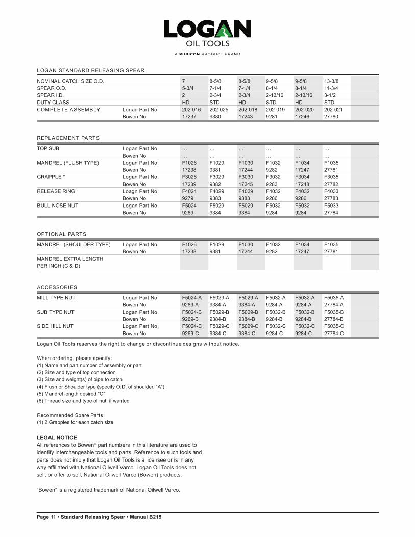
NOMINAL CATCH SIZE O.D. 7 8-5/8 8-5/8 9-5/8 9-5/8 13-3/8SPEAR O.D. 5-3/4 7-1/4 7-1/4 8-1/4 8-1/4 11-3/4SPEAR I.D. 2 2-3/4 2-3/4 2-13/16 2-13/16 3-1/2DUTY CLASS HD STD HD STD HD STDCOMPLETE ASSEMBLY Logan Part No. 202-016 202-025 202-018 202-019 202-020 202-021
Bowen No. 17237 9380 17243 9281 17246 27780
REPLACEMENT PARTS
TOP SUB Logan Part No. … … … … … …Bowen No. … … … … … …
MANDREL (FLUSH TYPE) Logan Part No. F1026 F1029 F1030 F1032 F1034 F1035Bowen No. 17238 9381 17244 9282 17247 27781
GRAPPLE * Logan Part No. F3026 F3029 F3030 F3032 F3034 F3035Bowen No. 17239 9382 17245 9283 17248 27782
RELEASE RING Loagn Part No. F4024 F4029 F4029 F4032 F4032 F4033Bowen No. 9279 9383 9383 9286 9286 27783
BULL NOSE NUT Logan Part No. F5024 F5029 F5029 F5032 F5032 F5033Bowen No. 9269 9384 9384 9284 9284 27784
OPTIONAL PARTS
MANDREL (SHOULDER TYPE) Logan Part No. F1026 F1029 F1030 F1032 F1034 F1035
Bowen No. 17238 9381 17244 9282 17247 27781MANDREL EXTRA LENGTHPER INCH (C & D)
ACCESSORIES
MILL TYPE NUT Logan Part No. F5024-A F5029-A F5029-A F5032-A F5032-A F5035-A
Bowen No. 9269-A 9384-A 9384-A 9284-A 9284-A 27784-ASUB TYPE NUT Logan Part No. F5024-B F5029-B F5029-B F5032-B F5032-B F5035-B
Bowen No. 9269-B 9384-B 9384-B 9284-B 9284-B 27784-BSIDE HILL NUT Logan Part No. F5024-C F5029-C F5029-C F5032-C F5032-C F5035-C
Bowen No. 9269-C 9384-C 9384-C 9284-C 9284-C 27784-C
Logan Oil Tools reserves the right to change or discontinue designs without notice.
When ordering, please specify:(1) Name and part number of assembly or part (2) Size and type of top connection (3) Size and weight(s) of pipe to catch (4) Flush or Shoulder type (specify O.D. of shoulder, “A”)(5) Mandrel length desired “C” (6) Thread size and type of nut, if wanted
Recommended Spare Parts:(1) 2 Grapples for each catch size

Manual B215 • Standard Releasing Spear • Page 10
10 • Logan St andard Releas ing Spear
LOGAN STANDARD RELEASING SPEAR
NOMINAL CATCH SIZE O.D. 4-1/2 4-1/2 5 5 6 6 7SPEAR O.D. 3-5/8 3-5/8 4-1/32 4-1/32 5 5 5-3/4SPEAR I.D. 3/4 3/4 7/8 1 1 1 2DUTY CLASS LD STD LD STD LD STD STDCOMPLETE ASSEMBLY Logan Part No. 202-017 202-012 202-035 202-013 202-023 202-014 202-015
Bowen No. 13200 17475 1332 9680 9715 17234 9266
REPLACEMENT PARTS
TOP SUB Logan Part No. … … … … … … …Bowen No. … … … … … … …
MANDREL (FLUSH TYPE) Logan Part No. F1016 F1017 F1018 F1019 F1022 F1023 F1024Bowen No. 13201 17476 1333 9681 9716 17235 9267
GRAPPLE * Logan Part No. F3016 F3017 F3018 F3019 F3022 F3023 F3024Bowen No. 13202 17477 1334 9682 9717 17236 9268
RELEASE RING Logan Part No. F4017 F4017 F4019 F4019 F4023 F4023 F4024Bowen No. 13183 13183 1336 1336 9718 9718 9279
BULL NOSE NUT Logan Part No. F5017 F5017 F5019 F5019 F5023 F5023 F5024Bowen No. 13184 13184 1335 1335 9719 9719 9269
OPTIONAL PARTS
MANDREL (SHOULDER TYPE) Logan Part No. F1016 F1017 F1018 F1019 F1022 F1023 F1024
Bowen No. 13201 17476 1333 9681 9716 17235 9267MANDREL EXTRA LENGTH Logan Part No. … … … … … … …PER INCH (C & D) Bowen No. … … … … … … …
ACCESSORIES
MILL TYPE NUT Logan Part No. F5017-A F5017-A F5019-A F5019-A F5023-A F5023-A F5024-A
Bowen No. 13184-A 13184-A 1335-A 1335-A 9719-A 9719-A 9269-ASUB TYPE NUT Logan Part No. F5017-B F5017-B F5019-B F5019-B F5023-B F5023-B F5024-B
Bowen No. 13184-B 13184-B 1335-B 1335-B 9719-B 9719-B 9269-BSIDE HILL NUT Logan Part No. F5017-C F5017-C F5019-C F5019-C F5023-C F5023-C F5024-C
Bowen No. 13184-C 13184-C 1335-C 1335-C 9719-C 9719-C 9269-C
Logan Oil Tools reserves the right to change or discontinue designs without notice.
When ordering, please specify:(1) Name and part number of assembly or part (2) Size and type of top connection (3) Size and weight(s) of pipe to catch (4) Flush or Shoulder type (specify O.D. of shoulder, “A”)(5) Mandrel length desired “C” (6) Thread size and type of nut, if wanted
Recommended Spare Parts:(1) 2 Grapples for each catch size
LEGAL NOTICEAll references to Bowen® part numbers in this literature are used to identify interchangeable tools and parts. Reference to such tools and parts does not imply that Logan Oil Tools is a licensee or is in any way affiliated with National Oilwell Varco. Logan Oil Tools does not sell, or offer to sell, National Oilwell Varco (Bowen) products.
“Bowen” is a registered trademark of National Oilwell Varco.
Manual B215 • Standard Releasing Spear • Page 12
MAK EUP TORQUE STRENGTH – LOGAN RELEASING SPEAR PACKOFF
RECOMMENDED MAKE UP TORQUE50% OF MAXIMUM MAKE UP TORQUE IN FT/LBS
ASSEMBLY ADAPTOR MANDREL RECOMMENDED MAXIMUM
400-037 F6001 F7001 100 200400-038 F6002 F7002 200 400400-039 F6003 F7003 175 350400-040 F6004 F7004 550 1,100400-041 F6005 F7005 1,250 2,500400-042 F6006 F7006 1,100 2,200400-043 F6007 F7006 1,100 2,200400-044 F6008 F7007 2,750 5,500400-045 F6009 F7007 2,750 5,500400-046 F6011 F7009 7,000 14,000400-047 F6011 F7009 7,000 14,000400-048 F6013 F7009 7,000 14,000400-055 F6013 F7009 7,000 14,000400-049 F6013 F7009 7,000 14,000400-066 F6013 F7009 7,000 14,000400-067 F6013 F7009 7,000 14,000400-068 F6013 F7009 7,000 14,000
Tool joint compound should be used on all connections before makeup. These torques are theoretical yield strengths and maximum recommended values. Thread life can be extended by using lower values.
12 • Logan St andard Releas ing Spear
MAK EUP TORQUE STRENGTH – LOGAN RELEASING SPEAR
MAX. MAKE UP TORQUE 50% OF YIELD IN FT-LBS LOAD CAPACITY AT YIELD POINT IN FT-LBSASSEMBLY MANDREL BULL NOSE NUT SUB TYPE NUT BULL NOSE NUT SUB TYPE NUT
202-001 F1000 12 12 24 24202-002 F1001 30 30 60 60202-003 F1002 45 45 90 90202-004 F1004 90 90 180 180202-036 F1005 210 210 420 420202-005 F1007 350 350 700 700202-006 F1008 350 350 700 700202-007 F1009 900 900 1,800 1,800202-008 F1010 900 900 1,800 1,800202-009 F1012 1,450 1,450 2,900 2,900202-011 F1015 3,000 3,000 6,000 6,000202-012 F1017 3,900 3,900 7,800 7,800202-035 F1018 5,900 5,900 11,800 11,800202-013 F1019 6,000 6,000 12,000 12,000202-023 F1022 10,000 10,000 20,000 20,000202-014 F1023 10,000 10,000 20,000 20,000202-015 F1024 8,750 8,750 17,500 17,500202-016 F1026 8,750 8,750 17,500 17,500202-025 F1029 21,000 21,000 42,000 42,000202-018 F1030 21,000 21,000 42,000 42,000202-019 F1032 9,500 35,000 19,000 70,000202-020 F1034 9,500 35,000 19,000 70,000202-021 F1035 25,000 100,000 50,000 200,000
Tool joint compound should be used on all connections before makeup. These torques are theoretical yield strengths and maximum recommended values. These are not required torques and thread life can be extended by using lower values.

Page 13 • Standard Releasing Spear • Manual B215
LOGAN SEGMENTED SPEAR GRAPPLE ASSEMBLY
Segment Body
Retainer Ring2 required
Retainer Ring Screw Spacer4 required
Grapple Segments 8 required
Grapple Segment Screw 16 required
Retainer Ring Screw 4 required
Logan Segm ent ed Spear Grapple Assem bly • 13
LOGAN SEGMENTED SPEAR GRAPPLE ASSEMBLY
ASSEMBLES TO SPEAR Logan Part No. 202-025 202-018Bowen No. 9380 17243
CATCH SIZE (PIPE SIZE) 10-3/4 11-3/4 12-3/4 13-3/8 10-3/4 11-3/4 12-3/4 13-3/8PIPE WEIGHT 32.75 38.00 45.45 48.00 32.75 38.00 45.45 48.60
48.00 54.00 66.72 68.00 48.00 54.00 66.72 68.0040.00 47.00 … 61.00 40.00 47.00 … 61.0055.50 60.00 … 85.00 55.50 60.00 … 85.00
COMPLETE ASSEMBLY Logan Part No. 205-000 205-001Bowen No. 9382 17245
GRAPPLE BODY Logan Part No. F3029-A F3030-ABowen No. 9382-A 17245-A
GRAPPLE SEGMENT Logan Part No. F3029-B F3030-B(8 per 1 set) Bowen No. 9382-B 17245-BSEGMENT SCREW Logan Part No. T3000 T3000
Bowen No. 12198 12198No. Req’d 16 16
RETAINER RING Logan Part No. T4000 T4000Bowen No. 56855 56855No. Req’d 2 2
RETAINER RING SCREW Logan Part No. T5000 T5000Bowen No. 23535 23535No. Req’d 4 4
RETAINER RING SCREW Logan Part No. T6000 T6000SPACER Bowen No. 56979 56979
No. Req’d 4 4LEGAL NOTICEAll references to Bowen® part numbers in this literature are used to identify interchangeable tools and parts. Reference to such tools and parts does not imply that Logan Oil Tools is a licensee or is in any way affiliated with National Oilwell Varco. Logan Oil Tools does not sell, or offer to sell, National Oilwell Varco (Bowen) products.
“Bowen” is a registered trademark of National Oilwell Varco.
LOGAN SEGMENTED SPEAR GRAPPLE ASSEMBLY
Segment Body
Retainer Ring2 required
Retainer Ring Screw Spacer4 required
Grapple Segments 8 required
Grapple Segment Screw 16 required
Retainer Ring Screw 4 required
Logan Segm ent ed Spear Grapple Assem bly • 13
LOGAN SEGMENTED SPEAR GRAPPLE ASSEMBLY
ASSEMBLES TO SPEAR Logan Part No. 202-025 202-018Bowen No. 9380 17243
CATCH SIZE (PIPE SIZE) 10-3/4 11-3/4 12-3/4 13-3/8 10-3/4 11-3/4 12-3/4 13-3/8PIPE WEIGHT 32.75 38.00 45.45 48.00 32.75 38.00 45.45 48.60
48.00 54.00 66.72 68.00 48.00 54.00 66.72 68.0040.00 47.00 … 61.00 40.00 47.00 … 61.0055.50 60.00 … 85.00 55.50 60.00 … 85.00
COMPLETE ASSEMBLY Logan Part No. 205-000 205-001Bowen No. 9382 17245
GRAPPLE BODY Logan Part No. F3029-A F3030-ABowen No. 9382-A 17245-A
GRAPPLE SEGMENT Logan Part No. F3029-B F3030-B(8 per 1 set) Bowen No. 9382-B 17245-BSEGMENT SCREW Logan Part No. T3000 T3000
Bowen No. 12198 12198No. Req’d 16 16
RETAINER RING Logan Part No. T4000 T4000Bowen No. 56855 56855No. Req’d 2 2
RETAINER RING SCREW Logan Part No. T5000 T5000Bowen No. 23535 23535No. Req’d 4 4
RETAINER RING SCREW Logan Part No. T6000 T6000SPACER Bowen No. 56979 56979
No. Req’d 4 4

Manual B215 • Standard Releasing Spear • Page 14
14 • Logan Segm ent ed Spear Grapple Assem bly
LOGAN SEGMENTED SPEAR GRAPPLE ASSEMBLY
ASSEMBLES TO SPEAR Logan Part No. 202-021Bowen No. 27780
CATCH SIZE (PIPE SIZE) 16 18-5/8 20PIPE WEIGHT 55.00 … 90.00
65.00 … 94.0084.00 … 133.00
COMPLETE ASSEMBLY Logan Part No. 205-004Bowen No. 27782
GRAPPLE BODY Logan Part No. F3035-ABowen No. 27782A
GRAPPLE SEGMENT Logan Part No. F3035-B(8 per 1 set) Bowen No. 27782BSEGMENT SCREW Logan Part No. T3002
Bowen No. 12019No. Req’d 16
RETAINER RING Logan Part No. T4002Bowen No. 56858No. Req’d 2
RETAINER Logan Part No. T5002RING SCREW Bowen No. 56859
No. Req’d 4RETAINER RING Logan Part No. T6000SCREW SPACER Bowen No. 56979
No. Req’d 4
Logan Oil Tools reserves the right to change or discontinue designs without notice.
LOGAN SEGMENTED SPEAR GRAPPLE ASSEMBLY
ASSEMBLES TO SPEAR Logan Part No. 202-019 202-020Bowen No. 9281 17246
CATCH SIZE (PIPE SIZE) 13-3/8 14 16 18-5/8 20 13-3/8 14 16 18-5/8 20PIPE WEIGHT 48.00 42.00 55.00 90.00 90.00 48.00 42.00 55.00 … 90.00
68.00 57.00 65.00 106.50 94.00 68.00 57.00 65.00 … 94.0061.00 … 84.00 … 106.00 61.00 … 84.00 … 133.0085.00 … 109.00 … 133.00 85.00 … … … …
COMPLETE ASSEMBLY Logan Part No. 205-002 205-003Bowen No. 9283 17248
GRAPPLE BODY Logan Part No. F3032-A F3034-ABowen No. 9283-A 17248-A
GRAPPLE SEGMENT Logan Part No. F3032-B F3034-B(8 per 1 set) Bowen No. 9283-B 17248-BSEGMENT SCREW Logan Part No. T3001 T3001
Bowen No. 23020 23020No. Req’d 16 16
RETAINER RING Logan Part No. T4001 T4001Bowen No. 56409 56409No. Req’d 2 2
RETAINER RING SCREW Logan Part No. T5001 T5001Bowen No. 56813 56813No. Req’d 4 4
RETAINER RING Logan Part No. T6000 T6000SCREW SPACER Bowen No. 56979 56979
No. Req’d 4 4
LEGAL NOTICEAll references to Bowen® part numbers in this literature are used to identify interchangeable tools and parts. Reference to such tools and parts does not imply that Logan Oil Tools is a licensee or is in any way affiliated with National Oilwell Varco. Logan Oil Tools does not sell, or offer to sell, National Oilwell Varco (Bowen) products.
“Bowen” is a registered trademark of National Oilwell Varco.
14 • Logan Segm ent ed Spear Grapple Assem bly
LOGAN SEGMENTED SPEAR GRAPPLE ASSEMBLY
ASSEMBLES TO SPEAR Logan Part No. 202-021Bowen No. 27780
CATCH SIZE (PIPE SIZE) 16 18-5/8 20PIPE WEIGHT 55.00 … 90.00
65.00 … 94.0084.00 … 133.00
COMPLETE ASSEMBLY Logan Part No. 205-004Bowen No. 27782
GRAPPLE BODY Logan Part No. F3035-ABowen No. 27782A
GRAPPLE SEGMENT Logan Part No. F3035-B(8 per 1 set) Bowen No. 27782BSEGMENT SCREW Logan Part No. T3002
Bowen No. 12019No. Req’d 16
RETAINER RING Logan Part No. T4002Bowen No. 56858No. Req’d 2
RETAINER Logan Part No. T5002RING SCREW Bowen No. 56859
No. Req’d 4RETAINER RING Logan Part No. T6000SCREW SPACER Bowen No. 56979
No. Req’d 4
Logan Oil Tools reserves the right to change or discontinue designs without notice.
LOGAN SEGMENTED SPEAR GRAPPLE ASSEMBLY
ASSEMBLES TO SPEAR Logan Part No. 202-019 202-020Bowen No. 9281 17246
CATCH SIZE (PIPE SIZE) 13-3/8 14 16 18-5/8 20 13-3/8 14 16 18-5/8 20PIPE WEIGHT 48.00 42.00 55.00 90.00 90.00 48.00 42.00 55.00 … 90.00
68.00 57.00 65.00 106.50 94.00 68.00 57.00 65.00 … 94.0061.00 … 84.00 … 106.00 61.00 … 84.00 … 133.0085.00 … 109.00 … 133.00 85.00 … … … …
COMPLETE ASSEMBLY Logan Part No. 205-002 205-003Bowen No. 9283 17248
GRAPPLE BODY Logan Part No. F3032-A F3034-ABowen No. 9283-A 17248-A
GRAPPLE SEGMENT Logan Part No. F3032-B F3034-B(8 per 1 set) Bowen No. 9283-B 17248-BSEGMENT SCREW Logan Part No. T3001 T3001
Bowen No. 23020 23020No. Req’d 16 16
RETAINER RING Logan Part No. T4001 T4001Bowen No. 56409 56409No. Req’d 2 2
RETAINER RING SCREW Logan Part No. T5001 T5001Bowen No. 56813 56813No. Req’d 4 4
RETAINER RING Logan Part No. T6000 T6000SCREW SPACER Bowen No. 56979 56979
No. Req’d 4 4

Page 15 • Standard Releasing Spear • Manual B215
Logan Releas ing Spear Grapple Range Char t • 15
LOGAN RELEASING SPEAR GRAPPLE RANGE CHART
LOGAN SPEAR GRAPPLE Logan Part No. F3000 F3000 F3000 F3000 F3000 F3000 F3000Bowen No. 16457 16457 16457 16457 16457 16457 16457
ACTUAL CATCHING RANGE: MINIMUM ID .725 .799 .850 .912 .932NOMINAL CATCH SIZE .742 .813 .864 .924 .944MAXIMUM ID .750 .824 .875 .937 .957OLD NOMINAL SIZE (INCHES) 3/4 ID & 3/4 Std Pipe .875 to .864 ID .937 ID .957 ID
3/4 X-STG .824 ID 1.0 to 2.25# 1" X-STG Pipe CS Hydril Pipe
LOGAN SPEAR GRAPPLE Logan Part No. F3000 F3000 F3000 F3000 F3001 F3001 F3001Bowen No. 16457 16457 16457 16457 19352 19352 19352
ACTUAL CATCHING RANGE: MINIMUM ID .955 .975 1.033 1.100 .913 .956 1.005NOMINAL CATCH SIZE .967 .987 1.049 1.112 .937 .978 1.027MAXIMUM ID .982 1.000 1.058 1.125 .957 1.000 1.049OLD NOMINAL SIZE (INCHES) .982 ID 1" ID 1" Std Pipe 1-1/8 ID .957 ID 1" ID 1.045 ID
1.049 ID 1" X-STG Pipe 1" Std Pipe
LOGAN SPEAR GRAPPLE Logan Part No. F3001 F3001 F3002 F3002 F3002 F3002 F3002
Bowen No. 19352 19352 11197 11197 11197 11197 11197
ACTUAL CATCHING RANGE: MINIMUM ID 1.050 1.081 1.137 1.180 1.211 1.242 1.273NOMINAL CATCH SIZE 1.072 1.103 1.170 1.215 1.246 1.277 1.308MAXIMUM ID 1.093 1.125 1.207 1.250 1.281 1.312 1.342OLD NOMINAL SIZE (INCHES) 1.093 ID 1.250 ID 1.187 ID 1.250 to 1.281 to 1.312 to 1.343 to
1.219 ID 1.250 ID 1.281 ID 1.312 ID
LOGAN SPEAR GRAPPLE Logan Part No. F3002 F3002 F3002 F3002 F3002 F3002 F3002Bowen No. 11197 11197 11197 11197 11197 11197 11197
ACTUAL CATCHING RANGE: MINIMUM ID 1.332 1.394 1.430 1.580 1.481 1.519 1.650NOMINAL CATCH SIZE 1.367 1.429 1.465 1.615 1.516 1.554 1.687MAXIMUM ID 1.402 1.464 1.500 1.652 1.551 1.589 1.720OLD NOMINAL SIZE (INCHES) 1-3/8 ID 1.438 ID 1.500 to 1-1/2 Std Pipe 1.531 ID 1 9/16 ID 1.687 to
1-1/4 Tbg 1.469 ID & 1-5/8 ID 1.700 ID
LOGAN SPEAR GRAPPLE Logan Part No. F3002 F3002 F3002 F3002 F3002 F3002 F3004
Bowen No. 11197 11197 11197 11197 11197 11197 9917
ACTUAL CATCHING RANGE: MINIMUM ID 1.722 1.771 1.836 1.895 1.957 2.024 1.441NOMINAL CATCH SIZE 1.757 1.806 1.875 1.930 1.992 2.061 1.470MAXIMUM ID 1.792 1.841 1.906 1.965 2.027 2.094 1.500OLD NOMINAL SIZE (INCHES) 1-3/4 to 1.815 ID 1-7/8 to 1-15/16 ID 2 ID 2.067 ID 1.500 ID to
1-25/32 ID 1-29/32 1-1/2 X-STG Pipe
Note: Grapples are stenciled with nominal catch size.
Logan Oil Tools reserves the right to change or discontinue designs without notice.
LEGAL NOTICEAll references to Bowen® part numbers in this literature are used to identify interchangeable tools and parts. Reference to such tools and parts does not imply that Logan Oil Tools is a licensee or is in any way affiliated with National Oilwell Varco. Logan Oil Tools does not sell, or offer to sell, National Oilwell Varco (Bowen) products.
“Bowen” is a registered trademark of National Oilwell Varco.

Manual B215 • Standard Releasing Spear • Page 16
LOGAN RELEASING SPEAR GRAPPLE RANGE CHART
LOGAN SPEAR GRAPPLE Logan Part No. F3004 F3004 F3004 F3004 F3004 F3004 F3004Bowen No. 9917 9917 9917 9917 9917 9917 9917
ACTUAL CATCHING RANGE: MINIMUM ID 1.470 1.472 1.553 1.566 1.598 1.612 1.673NOMINAL CATCH SIZE 1.500 1.502 1.583 1.596 1.628 1.642 1.700MAXIMUM ID 1.527 1.529 1.610 1.625 1.657 1.670 1.750OLD NOMINAL SIZE (INCHES) 1-1/2 Std Pipe 1-5/8 ID 1.657 ID 1.670 ID 1-3/4
to 1.610 ID 1.700 ID
LOGAN SPEAR GRAPPLE Logan Part No. … … … … … … …Bowen No. … … … … … … …Price … … … … … … …
LOGAN SPEAR GRAPPLE Logan Part No. F3004 F3004 F3004 F3004 F3004 F3005 F3005Bowen No. 9917 9917 9917 9917 9917 9647 9647
ACTUAL CATCHING RANGE: MINIMUM ID 1.707 1.742 1.817 1.881 1.942 1.677 1.742NOMINAL CATCH SIZE 1.737 1.772 1.847 1.911 1.972 1.719 1.778MAXIMUM ID 1.781 1.800 1.875 1.939 2.000 1.750 1.815OLD NOMINAL SIZE (INCHES) 1.781 ID 1.800 ID 1-7/8 ID 1.939 ID 2 ID 1.719 to 2-3/8 Drill
1.750 ID Pipe, 65.5#
LOGAN SPEAR GRAPPLE Logan Part No. … … … F3007 F3007 F3007 F3007Bowen No. … … … 1348 1348 1348 1348
LOGAN SPEAR GRAPPLE Logan Part No. F3005 F3005 F3005 F3008 F3008 F3008 F3008Bowen No. 9647 9647 9647 17230 17230 17230 17230
ACTUAL CATCHING RANGE: MINIMUM ID 1.802 1.864 1.968 1.788 1.796 1.889 1.952NOMINAL CATCH SIZE 1.838 1.900 2.004 1.828 1.836 1.929 1.992MAXIMUM ID 1.875 1.937 2.041 1.867 1.876 1.968 2.041OLD NOMINAL SIZE (INCHES) 1-7/8 & 1.875 to 2-3/8 Tbg, 1.867 ID 1.875 ID 1.937 to 2-3/8 Tbg,
1-27/32 ID 1.937 ID 4 to 4.7# Turn Body Turn Body 1.968 ID 4 to 4.7# Down Down
LOGAN SPEAR GRAPPLE Logan Part No. F3007 F3007 F3007 F3007 F3007 F3007 F3007Bowen No. 1348 1348 1348 1348 1348 1348 1348
LOGAN SPEAR GRAPPLE Logan Part No. F3008 F3008 F3008 F3008 F3008 F3008 F3008Bowen No. 17230 17230 17230 17230 17230 17230 17230
ACTUAL CATCHING RANGE: MINIMUM ID 1.983 2.045 2.091 2.170 2.186 2.233 2.249NOMINAL CATCH SIZE 2.023 2.085 2.131 2.211 2.226 2.273 2.289MAXIMUM ID 2.062 2.125 2.172 2.250 2.266 2.312 2.329OLD NOMINAL SIZE (INCHES) 2.000 to 2-1/8 ID 2-7/8 DP, 2-1/4 to 2-17/64 ID 2-5/16 ID 2-7/8 OD
2.062 ID 9.75 to 10.4# 2-3/16 ID 7.8 to 8.35# DP
Note: Grapples are stenciled with nominal catch size.
Logan Oil Tools reserves the right to change or discontinue designs without notice.
16 • Logan Releas ing Spear Grapple Range Char t
LEGAL NOTICEAll references to Bowen® part numbers in this literature are used to identify interchangeable tools and parts. Reference to such tools and parts does not imply that Logan Oil Tools is a licensee or is in any way affiliated with National Oilwell Varco. Logan Oil Tools does not sell, or offer to sell, National Oilwell Varco (Bowen) products.
“Bowen” is a registered trademark of National Oilwell Varco.

Page 17 • Standard Releasing Spear • Manual B215
Logan Releas ing Spear Grapple Range Char t • 17
LOGAN RELEASING SPEAR GRAPPLE RANGE CHART
LOGAN SPEAR GRAPPLE Logan Part No. F3007 F3007 F3007 F3007 F3007 F3007 F3007Bowen No. 1348 1348 1348 1348 1348 1348 1348
LOGAN SPEAR GRAPPLE Logan Part No. F3008 F3008 F3008 F3008 F3008 F3008 F3008Bowen No. 17230 17230 17230 17230 17230 17230 17230
ACTUAL CATCHING RANGE: MINIMUM ID 2.295 2.358 2.390 2.420 2.556 2.608 2.670NOMINAL CATCH SIZE 2.335 2.398 2.430 2.460 2.596 2.648 2.710MAXIMUM ID 2.375 2.438 2.469 2.500 2.625 2.688 2.750OLD NOMINAL SIZE (INCHES) 2-3/8 ID NX 2-3/8 ID 2-7/8 Tbg 2-7/16 ID 2-5/8 ID & 2-5/8 ID & 2-3/4 ID
1/2 Rod 2-7/16 ID 6.25-6.5#, 2-1/2 ID 2-9/16 ID 2-11/16 ID 2-7/8 OD
LOGAN SPEAR GRAPPLE Logan Part No. F3007 F3007 F3007 F3007 F3009 F3009 F3009
Bowen No. 1348 1348 1348 1348 1230 1230 1230
LOGAN SPEAR GRAPPLE Logan Part No. F3008 F3008 F3008 F3008 F3010 F3010 F3010Bowen No. 17230 17230 17230 17230 17233 17233 17233
ACTUAL CATCHING RANGE: MINIMUM ID 2.921 3.046 3.170 3.264 2.280 2.351 2.390NOMINAL CATCH SIZE 2.961 3.086 3.210 3.304 2.328 2.399 2.438MAXIMUM ID 3.000 3.126 3.250 3.344 2.375 2.446 2.487OLD NOMINAL SIZE (INCHES) 3 ID & 3-1/16 ID 3-1/4 ID & 3-11/32 ID 2-3/8 ID 2-3/8 to 2-7/8 Tbg
2-15/16 ID & 3-1/8 ID 3-3/16 ID & 3-9/32 ID 2-7/16 ID 6.25-6.5#, - NX DRIVE 2-7/8 OD
LOGAN SPEAR GRAPPLE Logan Part No. F3009 F3009 F3009 F3009 F3009 F3009 F3009
Bowen No. 1230 1230 1230 1230 1230 1230 1230
LOGAN SPEAR GRAPPLE Logan Part No. F3010 F3010 F3010 F3010 F3010 F3010 F3010Bowen No. 17233 17233 17233 17233 17233 17233 17233
ACTUAL CATCHING RANGE: MINIMUM ID 2.468 2.515 2.593 2.671 2.700 2.827 2.843NOMINAL CATCH SIZE 2.516 2.562 2.641 2.718 2.748 2.875 2.891MAXIMUM ID 2.563 2.610 2.688 2.766 2.813 2.922 2.938OLD NOMINAL SIZE (INCHES) 2.562 to 3-1/2 OD 2-11/16 3-1/2 OD 2-13/16 ID & 3-1/2 OD 2-7/8 to
2-15/32 ID 15.5# Drill 2-5/8 ID 12.4 to 13.3# 2-3/4 ID 10.2 to 11.2# 2-15/16 IDPipe Drill Pipe Drill Pipe
Note: Grapples are stenciled with nominal catch size.
Logan Oil Tools reserves the right to change or discontinue designs without notice.
LEGAL NOTICEAll references to Bowen® part numbers in this literature are used to identify interchangeable tools and parts. Reference to such tools and parts does not imply that Logan Oil Tools is a licensee or is in any way affiliated with National Oilwell Varco. Logan Oil Tools does not sell, or offer to sell, National Oilwell Varco (Bowen) products.
“Bowen” is a registered trademark of National Oilwell Varco.
Manual B215 • Standard Releasing Spear • Page 18
LOGAN RELEASING SPEAR GRAPPLE RANGE CHART
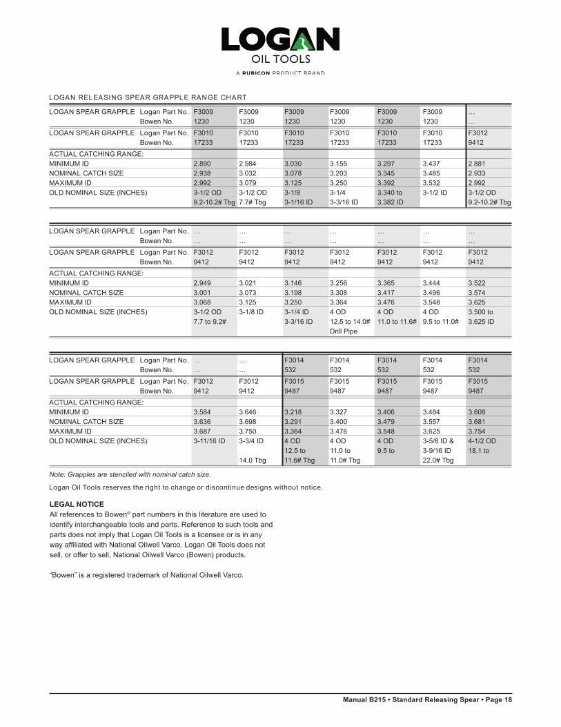
LOGAN SPEAR GRAPPLE Logan Part No. F3009 F3009 F3009 F3009 F3009 F3009 …Bowen No. 1230 1230 1230 1230 1230 1230 …
LOGAN SPEAR GRAPPLE Logan Part No. F3010 F3010 F3010 F3010 F3010 F3010 F3012Bowen No. 17233 17233 17233 17233 17233 17233 9412
ACTUAL CATCHING RANGE: MINIMUM ID 2.890 2.984 3.030 3.155 3.297 3.437 2.881NOMINAL CATCH SIZE 2.938 3.032 3.078 3.203 3.345 3.485 2.933MAXIMUM ID 2.992 3.079 3.125 3.250 3.392 3.532 2.992OLD NOMINAL SIZE (INCHES) 3-1/2 OD 3-1/2 OD 3-1/8 3-1/4 3.340 to 3-1/2 ID 3-1/2 OD
9.2-10.2# Tbg 7.7# Tbg 3-1/16 ID 3-3/16 ID 3.382 ID 9.2-10.2# Tbg
LOGAN SPEAR GRAPPLE Logan Part No. … … … … … … …
Bowen No. … … … … … … …
LOGAN SPEAR GRAPPLE Logan Part No. F3012 F3012 F3012 F3012 F3012 F3012 F3012Bowen No. 9412 9412 9412 9412 9412 9412 9412
ACTUAL CATCHING RANGE: MINIMUM ID 2.949 3.021 3.146 3.256 3.365 3.444 3.522NOMINAL CATCH SIZE 3.001 3.073 3.198 3.308 3.417 3.496 3.574MAXIMUM ID 3.068 3.125 3.250 3.364 3.476 3.548 3.625OLD NOMINAL SIZE (INCHES) 3-1/2 OD 3-1/8 ID 3-1/4 ID 4 OD 4 OD 4 OD 3.500 to
7.7 to 9.2# 3-3/16 ID 12.5 to 14.0# 11.0 to 11.6# 9.5 to 11.0# 3.625 IDDrill Pipe
LOGAN SPEAR GRAPPLE Logan Part No. … … F3014 F3014 F3014 F3014 F3014
Bowen No. … … 532 532 532 532 532
LOGAN SPEAR GRAPPLE Logan Part No. F3012 F3012 F3015 F3015 F3015 F3015 F3015Bowen No. 9412 9412 9487 9487 9487 9487 9487
ACTUAL CATCHING RANGE: MINIMUM ID 3.584 3.646 3.218 3.327 3.406 3.484 3.608NOMINAL CATCH SIZE 3.636 3.698 3.291 3.400 3.479 3.557 3.681MAXIMUM ID 3.687 3.750 3.364 3.476 3.548 3.625 3.754OLD NOMINAL SIZE (INCHES) 3-11/16 ID 3-3/4 ID 4 OD 4 OD 4 OD 3-5/8 ID & 4-1/2 OD
12.5 to 11.0 to 9.5 to 3-9/16 ID 18.1 to14.0 Tbg 11.6# Tbg 11.0# Tbg 22.0# Tbg
Note: Grapples are stenciled with nominal catch size.
Logan Oil Tools reserves the right to change or discontinue designs without notice.
18 • Logan Releas ing Spear Grapple Range Char t
LEGAL NOTICEAll references to Bowen® part numbers in this literature are used to identify interchangeable tools and parts. Reference to such tools and parts does not imply that Logan Oil Tools is a licensee or is in any way affiliated with National Oilwell Varco. Logan Oil Tools does not sell, or offer to sell, National Oilwell Varco (Bowen) products.
“Bowen” is a registered trademark of National Oilwell Varco.
Page 19 • Standard Releasing Spear • Manual B215
Logan Releas ing Spear Grapple Range Char t • 19
LOGAN RELEASING SPEAR GRAPPLE RANGE CHART
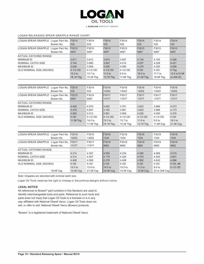
LOGAN SPEAR GRAPPLE Logan Part No. F3014 F3014 F3014 F3014 F3014 F3014 F3014Bowen No. 532 532 532 532 532 532 532
LOGAN SPEAR GRAPPLE Logan Part No. F3015 F3015 F3015 F3015 F3015 F3015 F3015Bowen No. 9487 9487 9487 9487 9487 9487 9487
ACTUAL CATCHING RANGE: MINIMUM ID 3.671 3.812 3.874 3.937 4.134 4.155 4.358NOMINAL CATCH SIZE 3.744 3.885 3.947 4.010 4.207 4.228 4.431MAXIMUM ID 3.826 3.958 4.026 4.090 4.276 4.300 4.506OLD NOMINAL SIZE (INCHES) 4-1/2 OD 4-1/2 OD 4-1/2 OD 4-1/2 OD 5 OD 5 OD 5 Tbg
15.3 to 13.7 to 11.0 to 9.5 to 18.0 to 17.7 to 12.6 to15.0# 18.1# Tbg 15.3# Tbg 13.7# Tbg 11.6# Tbg 21.0# Tbg 18.0# Tbg (4.408 ID)
LOGAN SPEAR GRAPPLE Logan Part No. F3014 F3014 F3016 F3016 F3016 F3016 F3016Bowen No. 532 532 13202 13202 13202 13202 13202
LOGAN SPEAR GRAPPLE Logan Part No. F3015 F3015 F3017 F3017 F3017 F3017 F3017Bowen No. 9487 9487 17477 17477 17477 17477 17477
ACTUAL CATCHING RANGE: MINIMUM ID 4.406 4.874 3.682 3.761 3.823 3.886 4.073NOMINAL CATCH SIZE 4.479 4.947 3.782 3.861 3.923 3.986 4.173MAXIMUM ID 4.560 5.012 3.881 3.958 4.026 4.090 4.276OLD NOMINAL SIZE (INCHES) 5 OD 5-1/2 OD 4-1/2 OD 4-1/2 OD 4-1/2 OD 4-1/2 OD 5 OD
11.5# Tbg 14.0 to 15.3 to 13.7 to 11.0 to 9.5 to 18.0 to17.0# Tbg 18.1# Tbg 15.3# Tbg 13.7# Tbg 11.6# Csg 21.0# Csg
LOGAN SPEAR GRAPPLE Logan Part No. F3016 F3016 F3018 F3018 F3018 F3018 F3018
Bowen No. 13202 13202 1334 1334 1334 1334 1334
LOGAN SPEAR GRAPPLE Logan Part No. F3017 F3017 F3019 F3019 F3019 F3019 F3019Bowen No. 17477 17477 9682 9682 9682 9682 9682
ACTUAL CATCHING RANGE: MINIMUM ID 4.214 4.307 4.093 4.234 4.390 4.469 4.515NOMINAL CATCH SIZE 4.314 4.407 4.179 4.320 4.476 4.555 4.601MAXIMUM ID 4.408 4.506 4.276 4.408 4.562 4.642 4.696OLD NOMINAL SIZE (INCHES) 5 OD 5 OD 5 OD 5 OD 5 OD 5 OD 5 OD, 8#
15.0 to 12.6 to 18.0 to 15.0 to 11.5 to 9.0 to 5-1/2 OD 18.0# Csg 15.0# Csg 21.0# Csg 18.0# Csg 15.0# Csg 13.0# Csg 23 to 25# Csg
Note: Grapples are stenciled with nominal catch size.
Logan Oil Tools reserves the right to change or discontinue designs without notice.
LEGAL NOTICEAll references to Bowen® part numbers in this literature are used to identify interchangeable tools and parts. Reference to such tools and parts does not imply that Logan Oil Tools is a licensee or is in any way affiliated with National Oilwell Varco. Logan Oil Tools does not sell, or offer to sell, National Oilwell Varco (Bowen) products.
“Bowen” is a registered trademark of National Oilwell Varco.

Manual B215 • Standard Releasing Spear • Page 20
LOGAN RELEASING SPEAR GRAPPLE RANGE CHART
LOGAN SPEAR GRAPPLE Logan Part No. F3018 F3018 F3018 F3018 F3018 F3018 F3018Bowen No. 1334 1334 1334 1334 1334 1334 1334
LOGAN SPEAR GRAPPLE Logan Part No. F3019 F3019 F3019 F3019 F3019 F3019 F3019Bowen No. 9682 9682 9682 9682 9682 9682 9682
ACTUAL CATCHING RANGE: MINIMUM ID 4.609 4.719 4.875 4.922 5.015 5.124 5.218NOMINAL CATCH SIZE 4.695 4.805 4.961 5.008 5.101 5.210 5.304MAXIMUM ID 4.782 4.892 5.048 5.095 5.192 5.297 5.390OLD NOMINAL SIZE (INCHES) 5 1/2 OD 5-1/2 OD 5-1/2 OD 5-3/4 OD 5-3/4, 5-3/4 OD 6 OD
20.0 to 17.0 to 14.0 to 19.5 to 17-19.5# 14.0 to 20.0# Csg to23.0# Csg 20.0# Csg 17.0# Csg 22.5# Csg 5 1/2 OD 17.0 Csg 23.0# Csg
9.0 to 13.0# Csg
LOGAN SPEAR GRAPPLE Logan Part No. F3018 F3018 F3018 F3022 F3022 F3022 F3022Bowen No. 1334 1334 1334 9717 9717 9717 9717
LOGAN SPEAR GRAPPLE Logan Part No. F3019 F3019 F3019 F3023 F3023 F3023 F3023Bowen No. 9682 9682 9682 17236 17236 17236 17236
ACTUAL CATCHING RANGE: MINIMUM ID 5.281 5.375 5.500 5.000 5.093 5.187 5.280NOMINAL CATCH SIZE 5.367 5.461 5.586 5.134 5.227 5.321 5.414MAXIMUM ID 5.454 5.552 5.675 5.266 5.360 5.454 5.547OLD NOMINAL SIZE (INCHES) 6 OD 6 OD 6-5/8 OD 6 OD 6 OD 6 OD 6 OD
17.0 to 14.0 to 32.0 to 23.0 to 20.0 to 17.0 to 14.0 to20.0# Csg 17.0# Csg 34.0# Csg 26.0# Csg 23.0# Csg 20.0# Csg 17.0# Csg
LOGAN SPEAR GRAPPLE Logan Part No. F3022 F3022 F3022 F3022 F3022 F3022 F3022Bowen No. 9717 9717 9717 9717 9717 9717 9717
LOGAN SPEAR GRAPPLE Logan Part No. F3023 F3023 F3023 F3023 F3023 F3023 F3023Bowen No. 17236 17236 17236 17236 17236 17236 17236
ACTUAL CATCHING RANGE: MINIMUM ID 5.406 5.530 5.593 5.656 5.671 5.781 5.796NOMINAL CATCH SIZE 5.540 5.664 5.727 5.790 5.805 5.915 5.930MAXIMUM ID 5.675 5.797 5.860 5.923 5.938 6.049 6.063OLD NOMINAL SIZE (INCHES) 6 OD 6-5/8 OD 6-5/8 OD 6-5/8 OD 7 OD 6-5/8 OD 7 OD
10.5 to 28.0 to 26.0 to 24.0 to 38.0 to 20.0 to 33.7 to 14.0# Csg 32.0# Csg 29.0# Csg 28.0# Csg 40.0# Csg 24.0# Csg 38.0# Csg
Note: Grapples are stenciled with nominal catch size.
Logan Oil Tools reserves the right to change or discontinue designs without notice.
20 • Logan Releas ing Spear Grapple Range Char t
LEGAL NOTICEAll references to Bowen® part numbers in this literature are used to identify interchangeable tools and parts. Reference to such tools and parts does not imply that Logan Oil Tools is a licensee or is in any way affiliated with National Oilwell Varco. Logan Oil Tools does not sell, or offer to sell, National Oilwell Varco (Bowen) products.
“Bowen” is a registered trademark of National Oilwell Varco.

Page 21 • Standard Releasing Spear • Manual B215
Logan Releas ing Spear Grapple Range Char t • 21
LOGAN RELEASING SPEAR GRAPPLE RANGE CHART
LOGAN SPEAR GRAPPLE Logan Part No. F3022 F3022 F3022 F3022 F3022 F3022 F3024Bowen No. 9717 9717 9717 9717 9717 9717 9268
LOGAN SPEAR GRAPPLE Logan Part No. F3023 F3023 F3023 F3023 F3023 F3023 F3026Bowen No. 17236 17236 17236 17236 17236 17236 17239
ACTUAL CATCHING RANGE: MINIMUM ID 5.875 5.937 6.015 6.140 6.202 6.281 5.770NOMINAL CATCH SIZE 6.009 6.071 6.149 6.274 6.335 6.415 5.970MAXIMUM ID 6.142 6.204 6.282 6.407 6.469 6.548 6.173OLD NOMINAL SIZE (INCHES) 6-5/8 OD 7 OD 7 OD 7 OD 7 OD 7 OD 7" 30.0-40.0#
17.0 to 29.0 to 26.0 to 22.0 to 20.0 to 17.0 to & 6-5/8 22.0# Csg 33.7# Csg 29.0# Csg 26.0# Csg 23.0# Csg 20.0# Csg 24.0# Csg
LOGAN SPEAR GRAPPLE Logan Part No. F3024 F3024 F3024 F3024 F3024 F3024 F3024Bowen No. 9268 9268 9268 9268 9268 9268 9268
LOGAN SPEAR GRAPPLE Logan Part No. F3026 F3026 F3026 F3026 F3026 F3026 F3026Bowen No. 17239 17239 17239 17239 17239 17239 17239
ACTUAL CATCHING RANGE: MINIMUM ID 5.895 6.020 6.270 6.364 6.567 6.864 6.987NOMINAL CATCH SIZE 6.095 6.220 6.470 6.564 6.767 7.064 7.187MAXIMUM ID 6.297 6.423 6.673 6.765 6.969 7.263 7.391OLD NOMINAL SIZE (INCHES) 7 OD 7 OD 7 OD 7-5/8 OD 7-5/8 OD 7-5/8 OD 8-1/8 OD
26.0 to 22.0 to 13.0 to 33.7 to 26.4 to 14.7 to 32.0 to35.0# Csg 33.7# Csg 24.0# Csg 45.0# Csg 39.0# Csg 26.4# Csg 42.0#Csg
LOGAN SPEAR GRAPPLE Logan Part No. F3024 F3024 F3024 F3024 F3024 F3024 F3024Bowen No. 9268 9268 9268 9268 9268 9268 9268
LOGAN SPEAR GRAPPLE Logan Part No. F3026 F3026 F3026 F3026 F3026 F3026 F3026Bowen No. 17239 17239 17239 17239 17239 17239 17239
ACTUAL CATCHING RANGE: MINIMUM ID 7.225 7.239 7.489 7.755 7.911 7.958 8.692NOMINAL CATCH SIZE 7.425 7.439 7.689 7.955 8.111 8.158 8.892MAXIMUM ID 7.628 7.642 7.892 8.157 8.313 8.360 9.094OLD NOMINAL SIZE (INCHES) 8 OD 7-9/16 ID 8-5/8 OD 8-5/8 24.0- 8-5/8 OD 9 OD 9-5/8 OD
16.0 to 34.0 to 38.0#, 17.6 to 34.0 to 29.3 to26.0# Csg 48.0# Csg 9" 55# Csg 29.3# Csg 45.0# Csg 42.0# Csg
Note: Grapples are stenciled with nominal catch size.
Logan Oil Tools reserves the right to change or discontinue designs without notice.
LEGAL NOTICEAll references to Bowen® part numbers in this literature are used to identify interchangeable tools and parts. Reference to such tools and parts does not imply that Logan Oil Tools is a licensee or is in any way affiliated with National Oilwell Varco. Logan Oil Tools does not sell, or offer to sell, National Oilwell Varco (Bowen) products.
“Bowen” is a registered trademark of National Oilwell Varco.

Manual B215 • Standard Releasing Spear • Page 22
LOGAN RELEASING SPEAR GRAPPLE RANGE CHART
LOGAN SPEAR GRAPPLE Logan Part No. F3024 F3029 F3029 F3029 F3029 F3029 F3029Bowen No. 9268 9382 9382 9382 9382 9382 9382
LOGAN SPEAR GRAPPLE Logan Part No. F3026 F3030 F3030 F3030 F3030 F3030 F3030Bowen No. 17239 17245 17245 17245 17245 17245 17245
ACTUAL CATCHING RANGE: MINIMUM ID 8.442 7.537 7.729 7.981 8.435 8.535 8.760NOMINAL CATCH SIZE 8.642 7.690 7.882 8.134 8.588 8.688 8.913MAXIMUM ID 8.884 7.846 8.034 8.315 8.755 8.846 9.065OLD NOMINAL SIZE (INCHES) 9-5/8 OD 8-5/8 OD 8-5/8 28.0 to 8-5/8 17.5 to 9 OD 19.0# 9-5/8 OD 9-5/8 OD
43.5 to 36.0 to 38.0#, 9 OD 29.3#, 9 OD & 9-5/8 OD 40.0 to 29.3 to53.5# Csg 48.0# Csg 45.0 to 34.0 to 43.5 to 53.5# Csg 42.0# Csg
55.0# Csg 45.0# Csg 58.0# Csg
LOGAN SPEAR GRAPPLE Logan Part No. F3029 205-000 * 205-000 * 205-000 * 205-000 * 205-000 * 205-000 *Bowen No. 9382 9382 9382 9382 9382 9382 9382
LOGAN SPEAR GRAPPLE Logan Part No. 205-001 * 205-001 * 205-001 * 205-001 * 205-001 * 205-001 * 205-001 *Bowen No. 17245 17245 17245 17245 17245 17245 17245
ACTUAL CATCHING RANGE: MINIMUM ID 9.479 9.760 9.885 10.729 10.854 12.228 12.415NOMINAL CATCH SIZE 9.632 9.913 10.038 10.882 11.007 12.381 12.568MAXIMUM ID 9.784 10.065 10.192 11.034 11.159 12.534 12.721OLD NOMINAL SIZE (INCHES) 10-3/4 OD 10-3/4 OD 10-3/4 OD 11-3/4 OD 11-3/4 OD 13-3/8 OD 13-3/8 OD
55.5 to 40.0 to 32.7 to 47.0 to 38.0 to 61.0 to 48.0 to65.7# Csg 55.5# Csg 48.0# Csg 60.0# Csg 54.0# Csg 85.0# Csg 68.0# Csg
LOGAN SPEAR GRAPPLE Logan Part No. F3032 F3032 F3032 F3032 F3032 F3032 F3032Bowen No. 9283 9283 9283 9283 9283 9283 9283
LOGAN SPEAR GRAPPLE Logan Part No. F3034 F3034 F3034 F3034 F3034 F3034 F3034Bowen No. 17248 17248 17248 17248 17248 17248 17248
ACTUAL CATCHING RANGE: MINIMUM ID 8.435 8.519 8.596 8.738 9.738 9.867 9.225NOMINAL CATCH SIZE 8.597 8.681 8.758 8.900 9.900 10.029 9.387MAXIMUM ID 8.755 8.844 8.921 9.063 10.063 10.192 9.550OLD NOMINAL SIZE (INCHES) 9-5/8 OD 9-5/8 OD 9-5/8 OD 9-5/8 OD 10-3/4 OD 10-3/4 OD 10-3/4 OD
43.5 to 40.0 to 36.0 to 29.3 to 40.0 to 32.7 to 71.0 to58.0# Csg 53.5# Csg 43.5# Csg 40.0# Csg 55.5# Csg 48.0# Csg 76.0# Csg
Note: Grapples are stenciled with nominal catch size
* Segmented grapples.
Logan Oil Tools reserves the right to change or discontinue designs without notice.
22 • Logan Releas ing Spear Grapple Range Char t
LEGAL NOTICEAll references to Bowen® part numbers in this literature are used to identify interchangeable tools and parts. Reference to such tools and parts does not imply that Logan Oil Tools is a licensee or is in any way affiliated with National Oilwell Varco. Logan Oil Tools does not sell, or offer to sell, National Oilwell Varco (Bowen) products.
“Bowen” is a registered trademark of National Oilwell Varco.

Page 23 • Standard Releasing Spear • Manual B215
Logan Releas ing Spear Grapple Range Char t • 23
LOGAN RELEASING SPEAR GRAPPLE RANGE CHART
LOGAN SPEAR GRAPPLE Logan Part No. 205-002 * F3032 F3032 F3032 F3032 205-002 * 205-002 *Bowen No. 9283 9283 9283 9283 9283 9283 9283
LOGAN SPEAR GRAPPLE Logan Part No. 205-003 * F3034 F3034 F3034 F3034 205-003 * 205-003 *Bowen No. 17248 17248 17248 17248 17248 17248 17248
ACTUAL CATCHING RANGE: MINIMUM ID 11.206 10.581 10.832 10.612 10.675 11.643 11.674NOMINAL CATCH SIZE 11.369 10.743 10.994 10.774 10.837 11.805 11.837MAXIMUM ID 11.531 10.906 11.157 10.937 11.000 11.968 12.000OLD NOMINAL SIZE (INCHES) 11.5 ID 11-3/4 OD 11-3/4 OD 11-3/4 OD 11-3/4 OD 13-3/8 OD 13-3/8 OD
54.0 to 38.0 to 60.0# Csg 47.0 to 11.937 ID 96.0#, 11.97565.0# Csg 54.0# Csg 60.0# Csg Csg ID Csg
LOGAN SPEAR GRAPPLE Logan Part No. 205-002 * 205-002 * 205-002 * 205-002 * 205-002 * 205-002 * 205-002 *Bowen No. 9283 9283 9283 9283 9283 9283 9283
LOGAN SPEAR GRAPPLE Logan Part No. 205-003 * 205-003 * 205-003 * 205-003 * 205-003 * 205-003 * 205-003 *Bowen No. 17248 17248 17248 17248 17248 17248 17248
ACTUAL CATCHING RANGE: MINIMUM ID 12.022 12.393 12.455 13.143 13.312 13.330 15.112NOMINAL CATCH SIZE 12.184 12.555 12.617 13.305 13.474 13.492 15.274MAXIMUM ID 12.347 12.718 12.780 13.468 13.637 13.655 15.437OLD NOMINAL SIZE (INCHES) 13-3/8 OD 13-3/8 OD 12-3/4 OD 14 OD 13.599 to 13-5/8 ID 16 OD
72.0 to 48.0 to 12-3/4 ID 42.0 to 13.609 ID 55.0 to85.0# Csg 68.0# Csg 57.0# Csg 75.0# Csg
LOGAN SPEAR GRAPPLE Logan Part No. 205-002 * 205-002 * 205-002 * 205-002 *Bowen No. 9283 9283 9283 9283
LOGAN SPEAR GRAPPLE Logan Part No. 205-003 * 205-003 * 205-003 * 205-003 *Bowen No. 17248 17248 17248 17248
ACTUAL CATCHING RANGE: MINIMUM ID 14.925 17.331 18.862 17.487NOMINAL CATCH SIZE 15.087 17.493 19.024 17.650MAXIMUM ID 15.250 17.656 19.187 17.812OLD NOMINAL SIZE (INCHES) 16 OD 17-1/2 ID 20 OD 18-5/8 OD
65.0 to 90.0 to 87.0# Csg 84.0# Csg 106.5# Csg
Note: Grapples are stenciled with nominal catch size
* Segmented grapples.
Logan Oil Tools reserves the right to change or discontinue designs without notice.
LEGAL NOTICEAll references to Bowen® part numbers in this literature are used to identify interchangeable tools and parts. Reference to such tools and parts does not imply that Logan Oil Tools is a licensee or is in any way affiliated with National Oilwell Varco. Logan Oil Tools does not sell, or offer to sell, National Oilwell Varco (Bowen) products.
“Bowen” is a registered trademark of National Oilwell Varco.

Manual B215 • Standard Releasing Spear • Page 24
* Grapples were marked with this description.
The strengths shown are theoretical calculations based on yield strength of the material used in each case. The strengths shown are therefore accurate, plus or minus 20% of the figures shown, only.
These figures do not constitute a guarantee, actual or implied. They are meant to serve only as a guide and appropriate safety factor allowance must be made in use.
ACTUAL CATCHING RANGE TENSILE STRENGTH LOGAN BOWEN MIN. NOMINAL MAX. GRAPPLE O.D. OF BODYASSY. NO. NO. I.D. CATCH SIZE I.D. OLD NOMINAL SIZE (INCHES) * – .000 / + .005 YIELD STRENGTH (lbs)
0.725 0.742 0.750 3/4 ID & 3/4 X-STG Pipe 0.7700.799 0.813 0.824 3/4 Std Pipe, .824 ID 0.8440.850 0.864 0.875 .875 to .864 ID, 1 to 2.25# CS Hydril 0.8950.912 0.924 0.937 .937 ID 0.957
F3000 16457 0.932 0.944 0.957 .957 ID, 1" X-STG Pipe 0.977 20,8000.955 0.967 0.982 .982 ID 1.0000.975 0.987 1.000 1 ID 1.0201.033 1.049 1.058 1.049 ID, 1" Std Pipe 1.0781.100 1.112 1.125 1-1/8 ID 1.1450.913 0.937 0.957 .957 ID – 1" X-STG Pipe 0.9880.956 0.978 1.000 1 ID 1.031
F3001 19352 1.005 1.027 1.049 1.045 ID, 1" Std Pipe 1.080 29,4001.050 1.072 1.093 1.093 ID 1.1251.081 1.103 1.125 1.250 ID 1.1561.137 1.170 1.207 1.187 ID 1.2271.180 1.215 1.250 1.250 to 1.219 ID 1.2701.211 1.246 1.281 1.281 to 1.250 ID 1.3011.242 1.277 1.312 1.312 to 1.281 ID 1.3321.273 1.308 1.342 1.343 to 1.312 ID 1.3631.332 1.367 1.402 1-3/8 ID, 1-1/4 Tbg 1.4221.394 1.429 1.464 1.438 ID 1.4841.430 1.465 1.500 1.500 to 1.469 ID 1.520
F3002 11197 1.580 1.615 1.652 1-1/2 Std Pipe & 1-5/8 ID 1.6721.481 1.516 1.551 1.531 ID 1.571 43,6001.519 1.554 1.589 1-9/16 ID 1.6091.650 1.687 1.720 1.687 to 1.700 ID 1.7401.722 1.757 1.792 1-3/4 to 1-25/32 ID 1.8121.771 1.806 1.841 1.815 ID 1.8611.836 1.875 1.906 1-7/8 to 1-29/32 ID 1.9361.895 1.930 1.965 1-15/16 ID 1.9851.957 1.992 2.027 2 ID 2.0472.024 2.061 2.094 2.067 ID 2.1141.441 1.470 1.500 1.500 ID to 1-1/2 X-STG Pipe 1.5461.470 1.500 1.527 … …1.472 1.502 1.529 … …1.553 1.583 1.610 1-1/2 Std Pipe to 1.610 ID 1.6581.566 1.596 1.625 1-5/8 ID 1.6711.598 1.628 1.657 1.657 ID 1.703
F3004 9917 1.612 1.642 1.670 1.670 ID 1.717 62,0001.673 1.700 1.734 1-3/4 1.700 ID 1.7811.707 1.737 1.765 1.781 ID 1.8121.742 1.772 1.800 1.800 ID 1.8471.817 1.847 1.875 1.7/8 ID 1.9221.881 1.911 1.939 1.939 ID 1.9861.942 1.972 2.000 2 ID 2.047
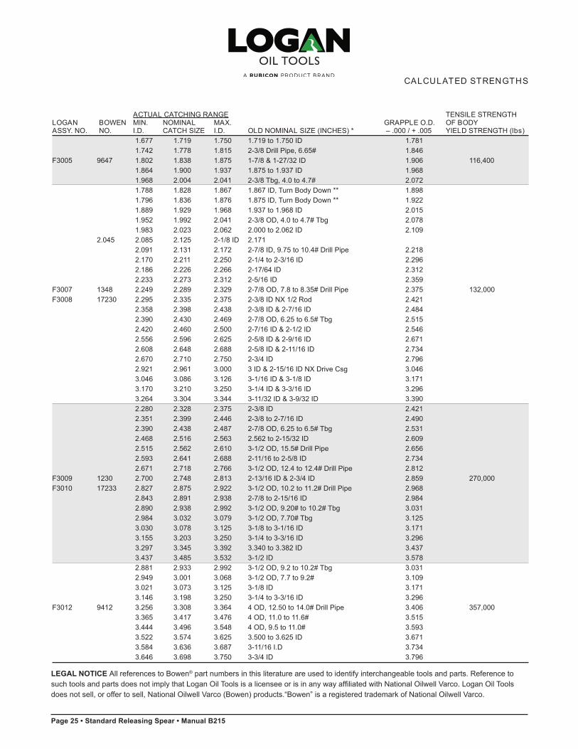
CALCULATED STRENGTHS
24 • Logan St andard Releas ing Spear
LEGAL NOTICE All references to Bowen® part numbers in this literature are used to identify interchangeable tools and parts. Reference to such tools and parts does not imply that Logan Oil Tools is a licensee or is in any way affiliated with National Oilwell Varco. Logan Oil Tools does not sell, or offer to sell, National Oilwell Varco (Bowen) products.“Bowen” is a registered trademark of National Oilwell Varco.
Page 25 • Standard Releasing Spear • Manual B215
Logan St andard Releas ing Spear • 25
CALCULATED STRENGTHS
ACTUAL CATCHING RANGE TENSILE STRENGTH LOGAN BOWEN MIN. NOMINAL MAX. GRAPPLE O.D. OF BODYASSY. NO. NO. I.D. CATCH SIZE I.D. OLD NOMINAL SIZE (INCHES) * – .000 / + .005 YIELD STRENGTH (lbs)
1.677 1.719 1.750 1.719 to 1.750 ID 1.7811.742 1.778 1.815 2-3/8 Drill Pipe, 6.65# 1.846
F3005 9647 1.802 1.838 1.875 1-7/8 & 1-27/32 ID 1.906 116,4001.864 1.900 1.937 1.875 to 1.937 ID 1.9681.968 2.004 2.041 2-3/8 Tbg, 4.0 to 4.7# 2.0721.788 1.828 1.867 1.867 ID, Turn Body Down ** 1.8981.796 1.836 1.876 1.875 ID, Turn Body Down ** 1.9221.889 1.929 1.968 1.937 to 1.968 ID 2.0151.952 1.992 2.041 2-3/8 OD, 4.0 to 4.7# Tbg 2.0781.983 2.023 2.062 2.000 to 2.062 ID 2.109
2.045 2.085 2.125 2-1/8 ID 2.1712.091 2.131 2.172 2-7/8 ID, 9.75 to 10.4# Drill Pipe 2.2182.170 2.211 2.250 2-1/4 to 2-3/16 ID 2.2962.186 2.226 2.266 2-17/64 ID 2.3122.233 2.273 2.312 2-5/16 ID 2.359
F3007 1348 2.249 2.289 2.329 2-7/8 OD, 7.8 to 8.35# Drill Pipe 2.375 132,000F3008 17230 2.295 2.335 2.375 2-3/8 ID NX 1/2 Rod 2.421
2.358 2.398 2.438 2-3/8 ID & 2-7/16 ID 2.4842.390 2.430 2.469 2-7/8 OD, 6.25 to 6.5# Tbg 2.5152.420 2.460 2.500 2-7/16 ID & 2-1/2 ID 2.5462.556 2.596 2.625 2-5/8 ID & 2-9/16 ID 2.6712.608 2.648 2.688 2-5/8 ID & 2-11/16 ID 2.7342.670 2.710 2.750 2-3/4 ID 2.7962.921 2.961 3.000 3 ID & 2-15/16 ID NX Drive Csg 3.0463.046 3.086 3.126 3-1/16 ID & 3-1/8 ID 3.1713.170 3.210 3.250 3-1/4 ID & 3-3/16 ID 3.2963.264 3.304 3.344 3-11/32 ID & 3-9/32 ID 3.3902.280 2.328 2.375 2-3/8 ID 2.4212.351 2.399 2.446 2-3/8 to 2-7/16 ID 2.4902.390 2.438 2.487 2-7/8 OD, 6.25 to 6.5# Tbg 2.5312.468 2.516 2.563 2.562 to 2-15/32 ID 2.6092.515 2.562 2.610 3-1/2 OD, 15.5# Drill Pipe 2.6562.593 2.641 2.688 2-11/16 to 2-5/8 ID 2.7342.671 2.718 2.766 3-1/2 OD, 12.4 to 12.4# Drill Pipe 2.812
F3009 1230 2.700 2.748 2.813 2-13/16 ID & 2-3/4 ID 2.859 270,000F3010 17233 2.827 2.875 2.922 3-1/2 OD, 10.2 to 11.2# Drill Pipe 2.968
2.843 2.891 2.938 2-7/8 to 2-15/16 ID 2.9842.890 2.938 2.992 3-1/2 OD, 9.20# to 10.2# Tbg 3.0312.984 3.032 3.079 3-1/2 OD, 7.70# Tbg 3.1253.030 3.078 3.125 3-1/8 to 3-1/16 ID 3.1713.155 3.203 3.250 3-1/4 to 3-3/16 ID 3.2963.297 3.345 3.392 3.340 to 3.382 ID 3.4373.437 3.485 3.532 3-1/2 ID 3.5782.881 2.933 2.992 3-1/2 OD, 9.2 to 10.2# Tbg 3.0312.949 3.001 3.068 3-1/2 OD, 7.7 to 9.2# 3.1093.021 3.073 3.125 3-1/8 ID 3.1713.146 3.198 3.250 3-1/4 to 3-3/16 ID 3.296
F3012 9412 3.256 3.308 3.364 4 OD, 12.50 to 14.0# Drill Pipe 3.406 357,0003.365 3.417 3.476 4 OD, 11.0 to 11.6# 3.5153.444 3.496 3.548 4 OD, 9.5 to 11.0# 3.5933.522 3.574 3.625 3.500 to 3.625 ID 3.6713.584 3.636 3.687 3-11/16 I.D 3.7343.646 3.698 3.750 3-3/4 ID 3.796
LEGAL NOTICE All references to Bowen® part numbers in this literature are used to identify interchangeable tools and parts. Reference to such tools and parts does not imply that Logan Oil Tools is a licensee or is in any way affiliated with National Oilwell Varco. Logan Oil Tools does not sell, or offer to sell, National Oilwell Varco (Bowen) products.“Bowen” is a registered trademark of National Oilwell Varco.
Manual B215 • Standard Releasing Spear • Page 26
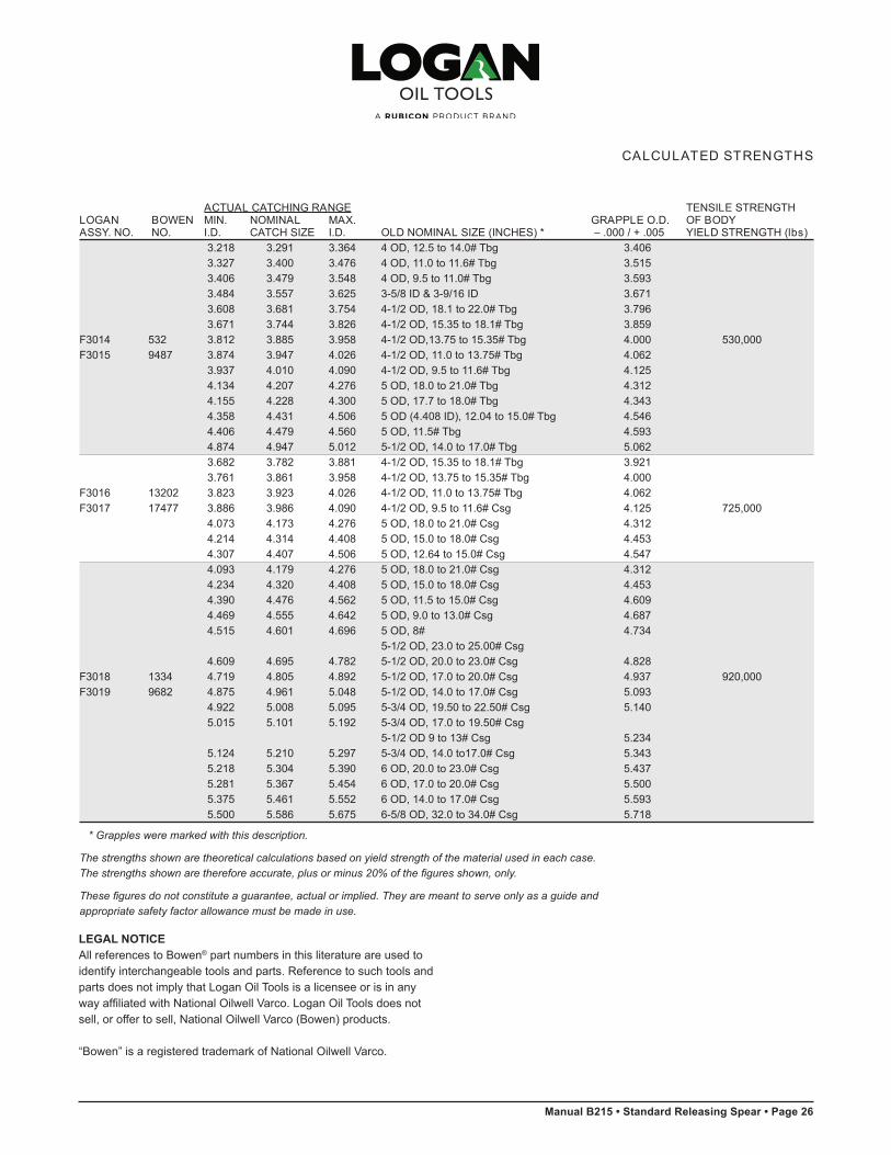
* Grapples were marked with this description.
The strengths shown are theoretical calculations based on yield strength of the material used in each case. The strengths shown are therefore accurate, plus or minus 20% of the figures shown, only.
These figures do not constitute a guarantee, actual or implied. They are meant to serve only as a guide and appropriate safety factor allowance must be made in use.
ACTUAL CATCHING RANGE TENSILE STRENGTH LOGAN BOWEN MIN. NOMINAL MAX. GRAPPLE O.D. OF BODYASSY. NO. NO. I.D. CATCH SIZE I.D. OLD NOMINAL SIZE (INCHES) * – .000 / + .005 YIELD STRENGTH (lbs)
3.218 3.291 3.364 4 OD, 12.5 to 14.0# Tbg 3.4063.327 3.400 3.476 4 OD, 11.0 to 11.6# Tbg 3.5153.406 3.479 3.548 4 OD, 9.5 to 11.0# Tbg 3.5933.484 3.557 3.625 3-5/8 ID & 3-9/16 ID 3.6713.608 3.681 3.754 4-1/2 OD, 18.1 to 22.0# Tbg 3.7963.671 3.744 3.826 4-1/2 OD, 15.35 to 18.1# Tbg 3.859
F3014 532 3.812 3.885 3.958 4-1/2 OD,13.75 to 15.35# Tbg 4.000 530,000 F3015 9487 3.874 3.947 4.026 4-1/2 OD, 11.0 to 13.75# Tbg 4.062
3.937 4.010 4.090 4-1/2 OD, 9.5 to 11.6# Tbg 4.1254.134 4.207 4.276 5 OD, 18.0 to 21.0# Tbg 4.3124.155 4.228 4.300 5 OD, 17.7 to 18.0# Tbg 4.343
4.358 4.431 4.506 5 OD (4.408 ID), 12.04 to 15.0# Tbg 4.546 4.406 4.479 4.560 5 OD, 11.5# Tbg 4.5934.874 4.947 5.012 5-1/2 OD, 14.0 to 17.0# Tbg 5.0623.682 3.782 3.881 4-1/2 OD, 15.35 to 18.1# Tbg 3.9213.761 3.861 3.958 4-1/2 OD, 13.75 to 15.35# Tbg 4.000
F3016 13202 3.823 3.923 4.026 4-1/2 OD, 11.0 to 13.75# Tbg 4.062F3017 17477 3.886 3.986 4.090 4-1/2 OD, 9.5 to 11.6# Csg 4.125 725,000
4.073 4.173 4.276 5 OD, 18.0 to 21.0# Csg 4.3124.214 4.314 4.408 5 OD, 15.0 to 18.0# Csg 4.4534.307 4.407 4.506 5 OD, 12.64 to 15.0# Csg 4.5474.093 4.179 4.276 5 OD, 18.0 to 21.0# Csg 4.3124.234 4.320 4.408 5 OD, 15.0 to 18.0# Csg 4.4534.390 4.476 4.562 5 OD, 11.5 to 15.0# Csg 4.6094.469 4.555 4.642 5 OD, 9.0 to 13.0# Csg 4.6874.515 4.601 4.696 5 OD, 8# 4.734
5-1/2 OD, 23.0 to 25.00# Csg4.609 4.695 4.782 5-1/2 OD, 20.0 to 23.0# Csg 4.828
F3018 1334 4.719 4.805 4.892 5-1/2 OD, 17.0 to 20.0# Csg 4.937 920,000F3019 9682 4.875 4.961 5.048 5-1/2 OD, 14.0 to 17.0# Csg 5.093
4.922 5.008 5.095 5-3/4 OD, 19.50 to 22.50# Csg 5.1405.015 5.101 5.192 5-3/4 OD, 17.0 to 19.50# Csg
5-1/2 OD 9 to 13# Csg 5.2345.124 5.210 5.297 5-3/4 OD, 14.0 to17.0# Csg 5.3435.218 5.304 5.390 6 OD, 20.0 to 23.0# Csg 5.4375.281 5.367 5.454 6 OD, 17.0 to 20.0# Csg 5.5005.375 5.461 5.552 6 OD, 14.0 to 17.0# Csg 5.5935.500 5.586 5.675 6-5/8 OD, 32.0 to 34.0# Csg 5.718
CALCULATED STRENGTHS
26 • Logan St andard Releas ing Spear
LEGAL NOTICEAll references to Bowen® part numbers in this literature are used to identify interchangeable tools and parts. Reference to such tools and parts does not imply that Logan Oil Tools is a licensee or is in any way affiliated with National Oilwell Varco. Logan Oil Tools does not sell, or offer to sell, National Oilwell Varco (Bowen) products.
“Bowen” is a registered trademark of National Oilwell Varco.

Page 27 • Standard Releasing Spear • Manual B215
Logan St andard Releas ing Spear • 27
CALCULATED STRENGTHS
* Grapples were marked with this description.** Segmented grapples
The strengths shown are theoretical calculations based on yield strength of the material used in each case. The strengths shown are therefore accurate, plus or minus 20% of the figures shown, only.
These figures do not constitute a guarantee, actual or implied. They are meant to serve only as a guide and appropriate safety factor allowance must be made in use.
ACTUAL CATCHING RANGE TENSILE STRENGTH LOGAN BOWEN MIN. NOMINAL MAX. GRAPPLE O.D. OF BODYASSY. NO. NO. I.D. CATCH SIZE I.D. OLD NOMINAL SIZE (INCHES) * – .000 / + .005 YIELD STRENGTH (lbs)
5.000 5.134 5.266 6 OD, 23.0 to 26.0# Csg 5.3125.093 5.227 5.360 6 OD, 20.0 to 23.0# Csg 5.4065.187 5.321 5.454 6 OD, 17.0 to 20.0# Csg 5.5005.280 5.414 5.547 6 OD, 14.0 to 17.0# Csg 5.5935.406 5.540 5.675 6 OD, 10.5 to 14.0# Csg 5.7185.530 5.664 5.797 6-5/8 OD, 28.0 to 32.0# Csg 5.8435.593 5.727 5.860 6-5/8 OD, 26.0 to 29.0# Csg 5.906
F3022 9717 5.656 5.790 5.923 6-5/8 OD, 24.0 to 28.0# Csg 5.968 1,175,000F3023 17236 5.671 5.805 5.938 7 OD, 38.0 to 40.0# Csg 5.984
5.781 5.915 6.049 6-5/8 OD, 20.0 to 24.0# Csg 6.0935.796 5.930 6.063 7 OD, 33.7 to 38.0# Csg 6.1095.875 6.009 6.142 6-5/8 OD, 17.0 to 22.0# Csg 6.1875.937 6.071 6.204 7 OD, 29.0 to 33.7# Csg 6.2506.015 6.149 6.282 7 OD, 26.0 to 29.0# Csg 6.3286.140 6.274 6.407 7 OD, 22.0 to 26.0# Csg 6.4536.202 6.335 6.469 7 OD, 20.0 to 23.0# Csg 6.5156.281 6.415 6.548 7 OD, 17.0 to 20.0# Csg 6.5935.770 5.970 6.173 7 OD, 30.0 to 40.0# & 6-5/8 OD, 24.0# Csg 6.2185.895 6.095 6.297 7 OD, 26.0 to 35.0# Csg 6.3436.020 6.220 6.423 7 OD, 22.0 to 33.7# Csg 6.4686.270 6.470 6.673 7 OD, 13.0 to 24.0# Csg 6.7186.364 6.564 6.765 7-5/8 OD, 33.7 to 45.0# Csg 6.8126.567 6.767 6.969 7-5/8 OD, 26.4 to 39.0# Csg 7.0156.864 7.064 7.263 7-5/8 OD, 14.75 to 26.4# Csg 7.312
F3024 9268 6.987 7.187 7.391 8-1/8 OD, 32.0 to 42.0# Csg 7.437 972,000F3026 17329 7.225 7.425 7.628 8 OD, 16.0 to 26.0# Csg 7.673
7.239 7.439 7.642 7-9/16 ID Csg 7.6877.489 7.689 7.892 8-5/8 OD, 34.0 to 48.0# Csg 7.9377.755 7.955 8.157 8-5/8 OD, 24.0 to 38.0# Csg & 8.203
9 OD, 40.0 to 55.0# Csg7.911 8.111 8.313 8-5/8 OD, 17.6 to 29.35# Csg 8.3597.958 8.158 8.360 9 OD, 34.0 to 45.0# Csg 8.4068.692 8.892 9.094 9-5/8 OD, 29.3 to 42.0# Csg 9.1408.442 8.642 8.844 9-5/8 OD, 43.5 to 53.5# Csg 8.890
LEGAL NOTICEAll references to Bowen® part numbers in this literature are used to identify interchangeable tools and parts. Reference to such tools and parts does not imply that Logan Oil Tools is a licensee or is in any way affiliated with National Oilwell Varco. Logan Oil Tools does not sell, or offer to sell, National Oilwell Varco (Bowen) products.
“Bowen” is a registered trademark of National Oilwell Varco.
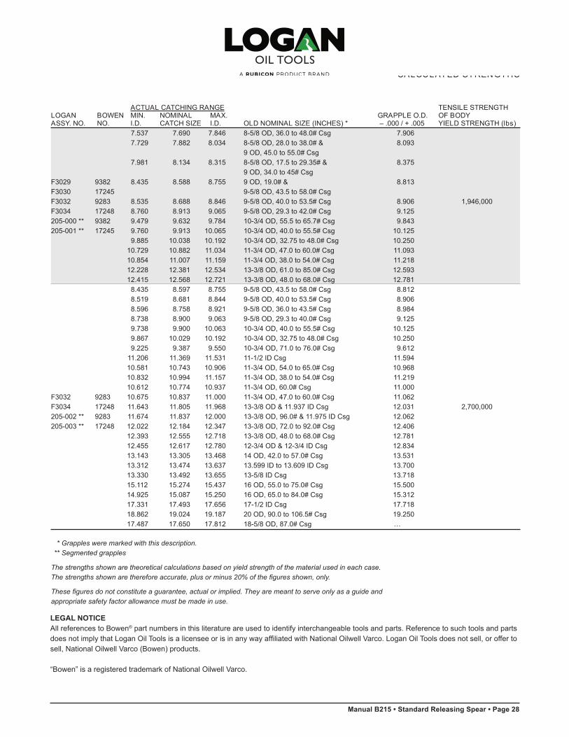
Manual B215 • Standard Releasing Spear • Page 28
LEGAL NOTICEAll references to Bowen® part numbers in this literature are used to identify interchangeable tools and parts. Reference to such tools and parts does not imply that Logan Oil Tools is a licensee or is in any way affiliated with National Oilwell Varco. Logan Oil Tools does not sell, or offer to sell, National Oilwell Varco (Bowen) products.
“Bowen” is a registered trademark of National Oilwell Varco.
28 • Logan St andard Releas ing Spear
CALCULATED STRENGTHS
ACTUAL CATCHING RANGE TENSILE STRENGTH LOGAN BOWEN MIN. NOMINAL MAX. GRAPPLE O.D. OF BODYASSY. NO. NO. I.D. CATCH SIZE I.D. OLD NOMINAL SIZE (INCHES) * – .000 / + .005 YIELD STRENGTH (lbs)
7.537 7.690 7.846 8-5/8 OD, 36.0 to 48.0# Csg 7.9067.729 7.882 8.034 8-5/8 OD, 28.0 to 38.0# & 8.093
9 OD, 45.0 to 55.0# Csg7.981 8.134 8.315 8-5/8 OD, 17.5 to 29.35# & 8.375
9 OD, 34.0 to 45# CsgF3029 9382 8.435 8.588 8.755 9 OD, 19.0# & 8.813F3030 17245 9-5/8 OD, 43.5 to 58.0# CsgF3032 9283 8.535 8.688 8.846 9-5/8 OD, 40.0 to 53.5# Csg 8.906 1,946,000F3034 17248 8.760 8.913 9.065 9-5/8 OD, 29.3 to 42.0# Csg 9.125205-000 ** 9382 9.479 9.632 9.784 10-3/4 OD, 55.5 to 65.7# Csg 9.843205-001 ** 17245 9.760 9.913 10.065 10-3/4 OD, 40.0 to 55.5# Csg 10.125
9.885 10.038 10.192 10-3/4 OD, 32.75 to 48.0# Csg 10.25010.729 10.882 11.034 11-3/4 OD, 47.0 to 60.0# Csg 11.09310.854 11.007 11.159 11-3/4 OD, 38.0 to 54.0# Csg 11.21812.228 12.381 12.534 13-3/8 OD, 61.0 to 85.0# Csg 12.59312.415 12.568 12.721 13-3/8 OD, 48.0 to 68.0# Csg 12.781
8.435 8.597 8.755 9-5/8 OD, 43.5 to 58.0# Csg 8.8128.519 8.681 8.844 9-5/8 OD, 40.0 to 53.5# Csg 8.9068.596 8.758 8.921 9-5/8 OD, 36.0 to 43.5# Csg 8.9848.738 8.900 9.063 9-5/8 OD, 29.3 to 40.0# Csg 9.1259.738 9.900 10.063 10-3/4 OD, 40.0 to 55.5# Csg 10.1259.867 10.029 10.192 10-3/4 OD, 32.75 to 48.0# Csg 10.2509.225 9.387 9.550 10-3/4 OD, 71.0 to 76.0# Csg 9.612
11.206 11.369 11.531 11-1/2 ID Csg 11.59410.581 10.743 10.906 11-3/4 OD, 54.0 to 65.0# Csg 10.96810.832 10.994 11.157 11-3/4 OD, 38.0 to 54.0# Csg 11.21910.612 10.774 10.937 11-3/4 OD, 60.0# Csg 11.000
F3032 9283 10.675 10.837 11.000 11-3/4 OD, 47.0 to 60.0# Csg 11.062F3034 17248 11.643 11.805 11.968 13-3/8 OD & 11.937 ID Csg 12.031 2,700,000205-002 ** 9283 11.674 11.837 12.000 13-3/8 OD, 96.0# & 11.975 ID Csg 12.062205-003 ** 17248 12.022 12.184 12.347 13-3/8 OD, 72.0 to 92.0# Csg 12.406
12.393 12.555 12.718 13-3/8 OD, 48.0 to 68.0# Csg 12.78112.455 12.617 12.780 12-3/4 OD & 12-3/4 ID Csg 12.83413.143 13.305 13.468 14 OD, 42.0 to 57.0# Csg 13.53113.312 13.474 13.637 13.599 ID to 13.609 ID Csg 13.70013.330 13.492 13.655 13-5/8 ID Csg 13.71815.112 15.274 15.437 16 OD, 55.0 to 75.0# Csg 15.50014.925 15.087 15.250 16 OD, 65.0 to 84.0# Csg 15.31217.331 17.493 17.656 17-1/2 ID Csg 17.71818.862 19.024 19.187 20 OD, 90.0 to 106.5# Csg 19.250 17.487 17.650 17.812 18-5/8 OD, 87.0# Csg …
* Grapples were marked with this description.** Segmented grapples
The strengths shown are theoretical calculations based on yield strength of the material used in each case. The strengths shown are therefore accurate, plus or minus 20% of the figures shown, only.
These figures do not constitute a guarantee, actual or implied. They are meant to serve only as a guide and appropriate safety factor allowance must be made in use.

Page 29 • Standard Releasing Spear • Manual B215
Logan Releas ing Spear Pac k -of f Assem bly • 29
LOGAN RELEASING SPEAR PACK -OFF ASSEMBLY
CASING SIZE TO PACK OFF 1-1/2 Tbg 2-3/8 Tbg 2-3/8 Tbg 2-7/8 Tbg 2-7/8 Tbg 3-1/2 Tbg 3-1/2 Tbg4.6# 6.5# … 8.5–10.2#
OD ADAPTER SUB (INCHES) 1-3/8 1-7/8 1-7/8 1-13/16 1-13/16 2-1/2 2-1/2PACK -OFF ASSEMBLY Logan Part No. 400-036 400-037 400-037 400-038 400-038 400-039 400-039
MANDREL Logan Part No. F6000 F6001 F6001 F6002 F6002 F6003 F6003OD of Mandrel Stem (Inches) … 1.063 1.063 1.327 1.327 1.250 1.250ADAPTER SUB Logan Part No. F7000 F7001 F7001 F7002 F7002 F7003 F7003PACKING CUP Logan Part No. F8000 F8001 F8001-001 F8002 F8002-001 F8003 F8003-001
Reference No. … … 10716 … 10047 … 14960THIMBLE Logan Part No. F9000 F9001 F9001-001 F9002 F9002-001 F9003 F9003-001 ID of Packing Cup & Thimble (Inches) … … 1.094 … 1.344 … 1.344STABILIZER Logan Part No. F10000 F10001 F10001-001 F10002 F10002-001 F10003 F10003-001
CASING SIZE TO PACK OFF 3-1/2 Tbg 4 Tbg 4 Tbg 4-1/2 Tbg, 4-1/2 Tbg 4-1/2 Tbg 5 Csg12.8–13.7# 9.5–11.6# 1/2 Csg & 9.5–12.6# 13.5–18.1# 3/4 Csg & 4-3/4 16#
OD ADAPTER SUB (INCHES) 2-1/2 3-1/4 3-1/4 3-1/2 3-1/2 3-1/2 4PACK -OFF ASSEMBLY Logan Part No. 400-039 400-040 400-040 400-041 400-041 400-041 400-042
MANDREL Logan Part No. F6003 F6004 F6004 F6005 F6005 F6005 F6006OD of Mandrel Stem (Inches) 1.250 1.906 1.906 2.375 2.375 2.375 2.375ADAPTER SUB Logan Part No. F7003 F7004 F7004 F7005 F7005 F7005 F7006PACKING CUP Logan Part No. F8003-001 F8004 F8004-001 F8005 F8005-001 F8005-002 F8006
Reference No. 14082 … 14036 … 30509 10430 …THIMBLE Logan Part No. F9003-001 F9004 F9004-001 F9005 F9005-001 F9005-002 F9006ID of Packing Cup & Thimble (Inches) 1.344 … 1.94 … 2.41 2.41 …STABILIZER Logan Part No. F10003 F10004 F10004-001 F10005 F10005-001 F10005-002 F10006
CASING SIZE TO PACK OFF 5 Csg 5 Csg 5-1/2 & 5-1/2 Csg 5-1/2 Csg 5-1/2 Csg 5-3/4 Csg13–15# 18–21# 5-3/4 Csg 13–15# & 15.5–17# 17–23# 14–18# & 5-3/4 Csg 6 Csg 20# 19.5–22.5#
OD ADAPTER SUB (INCHES) 4 4 4 4 4 4 4PACK -OFF ASSEMBLY Logan Part No. 400-042 400-042 400-043 400-043 400-043 400-043 400-043
MANDREL Logan Part No. F6006 F6006 F6007 F6007 F6007 F6007 F6007OD of Mandrel Stem (Inches) 2.375 2.375 2.900 2.900 2.900 2.900 …ADAPTER SUB Logan Part No. F7006 F7006 F7006 F7006 F7006 F7006 F7006PACKING CUP Logan Part No. F8006-002 F8006-001 F8007 F8007-001 F8007-003 F8007-002 F8007-005
Reference No. 25389 17831 … 22624 22626 19710 14714THIMBLE Logan Part No. F9006-*** F9006-001 F9007 F9007-001 F9007-001 F9007-001 F9007-003ID of Packing Cup & Thimble (Inches) 2.41 2.41 … 2.91 2.91 2.91 2.91STABILIZER Logan Part No. F10006 F10006-001 F10007 F10007 * F10007-002 F10007-002 F10007-002
Logan Oil Tools reserves the right to change or discontinue designs without notice.
* Sequence number to be determined
When ordering, please specify:(1) Name and part number of assembly or part (2) Size and type of top connection (3) Size and weight of pipe to be run in
Recommended Spare Parts:(1) 2 Packers for each size (2) 1 Thimble for each size

Manual B215 • Standard Releasing Spear • Page 30
LOGAN RELEASING SPEAR PACK -OFF ASSEMBLY
CASING SIZE TO PACK OFF 6 Csg 6 Csg 6-5/8, 7 & 6-5/8 Csg 6-5/8 Csg 6-5/8 7 Csg14–18# 7-5/8 Csg 20–22# & 24–29# & 32# 17–20#
7 Csg 7 Csg 38# 32–35.3#
OD ADAPTER SUB (INCHES) 4-3/4 4-3/4 4-3/4 4-3/4 4-3/4 4-3/4 4-3/4PACK -OFF ASSEMBLY Logan Part No. 400-044 400-044 400-045 400-045 400-045 400-045 400-045
MANDREL Logan Part No. F6008 F6008 F6009 F6009 F6009 F6009 F6009OD of Mandrel Stem (Inches) … … 3.500 3.500 3.500 3.500 3.500ADAPTER SUB Logan Part No. F7007 F7007 F7007 F7007 F7007 F7007 F7007PACKING CUP Logan Part No. F8008 F8008-002 F8009 F8009-002 F8009-003 F8009-017 F8009-009
Reference No. … 14721 … 19389 19277 19278 17819THIMBLE Logan Part No. F9008 F9008-001 F9009 F9009-001 F9009-001 F9009-001 F9009-004ID of Packing Cup & Thimble (Inches) … 2.91 … 3.53 3.53 3.53 3.53STABILIZER Logan Part No. F10008 F10007-003 F10009 F10009-002 F10009-002 F10009-002 F10009-002
CASING SIZE TO PACK OFF 7 Csg 7 Csg 7-5/8 Csg 7-5/8 Csg 7-5/8 Csg 8-1/8 Csg 8-1/8 Csg22–24# 26–30# 26.4–29.7# 29.7–33.7# 39–42.8# 35.5# WP 39.5# WP
OD ADAPTER SUB (INCHES) 4-3/4 4-3/4 4-3/4 4-3/4 4-3/4 4-3/4 4-3/4PACK -OFF ASSEMBLY Logan Part No. 400-045 400-045 400-045 400-045 400-045 400-045 400-045
MANDREL Logan Part No. F6009 F6009 F6009 F6009 F6009 F6009 F6009OD of Mandrel Stem (Inches) 3.500 3.500 3.500 3.500 3.500 3.500 3.500ADAPTER SUB Logan Part No. F7007 F7007 F7007 F7007 F7007 F7007 F7007PACKING CUP Logan Part No. F8009-008 F8009-001 F8009-004 F8009-005 F8009-006 F8009-011 F8009-018
Reference No. 17461 17356 13931 21293 23051 … E107581 WR35318
THIMBLE Logan Part No. F9009-004 F9009-002 F9009-003 F9009-003 F9009-003 F9009-006 F9009-006ID of Packing Cup & Thimble (Inches) 3.53 3.53 3.53 3.53 3.53 3.53 3.53STABILIZER Logan Part No. F10009-002 F10009 F10009-003 F10009-003 F10009-003 F10009-004 F10009 *
CASING SIZE TO PACK OFF 8-5/8 Csg 8, 8-5/8 8-5/8 Csg 8-5/8 Csg 8-5/8 Csg 9-5/8 Csg 9-5/8 Csg20–24# & 9 Csg 28–36# 36–40# 40–49# 36–43.5# & 10-3/4 Csg 99.5#
OD ADAPTER SUB (INCHES) 4-3/4 6-1/8 6-1/8 6-1/8 6-1/8 6-3/8 6-3/8PACK -OFF ASSEMBLY Logan Part No. 400-045 400-046 400-046 400-046 400-046 400-047 400-047
MANDREL Logan Part No. F6009 F6011 F6011 F6011 F6011 F6011 F6011OD of Mandrel Stem (Inches) 3.500 4.500 4.500 4.500 4.500 4.500 4.500ADAPTER SUB Logan Part No. F7007 F7009 F7009 F7009 F7009 F7009 F7009PACKING CUP Logan Part No. F8009-010 F8010 F8009-014-001F8009-019 F8009-013 F8011 F8011-001
Reference No. … … 16111 16113 16115 … 10354THIMBLE Logan Part No. F9009-006 F9010 F9010 F9010 F9009-007 F9011 F9011-001 ID of Packing Cup & Thimble (Inches) 3.53 4.53 4.53 4.53 4.53 4.53 4.53STABILIZER Logan Part No. F10009 * F10011 F10011 F10011 F10011 F10011 F10011-001
Logan Oil Tools reserves the right to change or discontinue designs without notice.
* Sequence number to be determined
When ordering, please specify:(1) Name and part number of assembly or part (2) Size and type of top connection (3) Size and weight of pipe to be run in
Recommended Spare Parts:(1) 2 Packers for each size (2) 1 Thimble for each size
30 • Logan Releas ing Spear Pac k -of f Assem bly

Page 31 • Standard Releasing Spear • Manual B215
Logan Releas ing Spear Pac k -of f Assem bly • 31
LOGAN RELEASING SPEAR PACK -OFF ASSEMBLY
CASING SIZE TO PACK OFF 9-5/8 Csg 10-3/4 Csg 10-3/4 Csg 10-3/4 Csg 11-3/4 Csg 11-3/4 Csg 11-3/4 Csg 47–59.4# & 32.75–55.5# 55.5–65.7# 38–60# 65#9-7/8 Csg 62.8#
OD ADAPTER SUB (INCHES) 6-3/8 8 8 8 8 8 8PACK -OFF ASSEMBLY Logan Part No. 400-047 400-048 400-048 400-048 400-055 400-055 400-055
MANDREL Logan Part No. F6011 F6013 F6013 F6013 F6013 F6013 F6013OD of Mandrel Stem (Inches) 4.500 4.500 4.500 4.500 4.500 4.500 4.500ADAPTER SUB Logan Part No. F7009 F7009 F7009 F7009 F7009 F7009 F7009PACKING CUP Logan Part No. F8011-002 F8012 F8012-001 F8012-002 F80125 F80125-001 F80125-002
Reference No. 33850 … 13197 13198 … 14246 E111751 WR45318
THIMBLE Logan Part No. F9011-002 F9012 F9012-001 F9012-002 F90125 F90125-001 F90125-001ID of Packing Cup & Thimble (Inches) 4.53 4.53 4.53 4.53 4.53 4.53 4.53STABILIZER Logan Part No. F10011-001 F10012 F10012-001 F10012-003 F100125 F100125-001 F100125 *
CASING SIZE TO PACK OFF 11-3/4 Csg 11-7/8 Csg 13-3/8 & 13-3/8 Csg 13-3/8 Csg 14 Csg 16 Csg71# 71.8# 13-5/8 Csg 48–72# & 72–85# 101# 13-5/8 88.2#
OD ADAPTER SUB (INCHES) 8 8 8 8 8 8 8PACK -OFF ASSEMBLY Logan Part No. 400-055 400-055 400-049 400-049 400-049 400-049 400-066
MANDREL Logan Part No. F6013 F6013 F6013 F6013 F6013 F6013 F6013OD of Mandrel Stem (Inches) 4.500 4.500 4.500 4.500 4.500 4.500 4.500ADAPTER SUB Logan Part No. F7009 F7009 F7009 F7009 F7009 F7009 F7009PACKING CUP Logan Part No. F80125-004 F80125-003 F8013 F8013-001 F8013-002 F8013-003 F8014
Reference No. E111751 E111783 … 16298 * * E116065WR45318 ECP45318 45318
THIMBLE Logan Part No. F90125-001 F90125-001 F9013 F9013-001 F9013-001 F90013-001 Not Req’dID of Packing Cup & Thimble (Inches) 4.53 4.53 4.53 4.53 4.53 4.53 …STABILIZER Logan Part No. F100125 * F100125 * F10013 F10013-001 F10013 * F10013 * F10014
Logan Oil Tools reserves the right to change or discontinue designs without notice.
* Sequence number to be determined
When ordering, please specify:(1) Name and part number of assembly or part (2) Size and type of top connection (3) Size and weight of pipe to be run in
Recommended Spare Parts:(1) 2 Packers for each size (2) 1 Thimble for each size

Manual B215 • Standard Releasing Spear • Page 32
32 • Logan Releas ing Spear Pac k -of f Assem bly
CASING SIZE TO PACK OFF 20 Csg 20 Csg 20 Csg 20 Csg94# 106# 133# 203.11#
OD ADAPTER SUB (INCHES) 8 8 8 8PACK -OFF ASSEMBLY Logan Part No. 400-068 400-068 400-068 400-068
MANDREL Logan Part No. F6013 F6013 F6013 F6013OD of Mandrel Stem (Inches) 4.500 4.500 4.500 4.500ADAPTER SUB Logan Part No. F7009 F7009 F7009 F7009PACKING CUP Logan Part No. F8016-002 F8016-001 F8016-003 F8016-004
Reference No. * * * *THIMBLE Logan Part No. Not Req’d Not Req’d Not Req’d Not Req’dID of Packing Cup & Thimble (Inches) … … … …STABILIZER Logan Part No. F10016-001 F10016-001 F10016-001 F10016 *
Logan Oil Tools reserves the right to change or discontinue designs without notice.
* Sequence number to be determined
When ordering, please specify:(1) Name and part number of assembly or part (2) Size and type of top connection (3) Size and weight of pipe to be run in
Recommended Spare Parts:(1) 2 Packers for each size (2) 1 Thimble for each size
LOGAN RELEASING SPEAR PACK -OFF ASSEMBLY
CASING SIZE TO PACK OFF 16 Csg 16 Csg 16 Csg 16 Csg 18-5/8 Csg 18-5/8 Csg 20 Csg65# 84# 97# 109# 87.5#
OD ADAPTER SUB (INCHES) 8 8 8 8 8 8 8PACK -OFF ASSEMBLY Logan Part No. 400-066 400-066 400-066 400-066 400-067 400-067 400-068
MANDREL Logan Part No. F6013 F6013 F6013 F6013 F6013 F6013 F6013OD of Mandrel Stem (Inches) 4.500 4.500 4.500 4.500 4.500 4.500 4.500ADAPTER SUB Logan Part No. F7009 F7009 F7009 F7009 F7009 F7009 F7009PACKING CUP Logan Part No. F8014-002 F8014-001 F8014-004 F8014-003 F8015 F8015-001 F8016
Reference No. E116065 E116084 * * … … *45318 45318
THIMBLE Logan Part No. Not Req’d Not Req’d Not Req’d Not Req’d Not Req’d Not Req’d Not Req’dID of Packing Cup & Thimble (Inches) … … … … … … …STABILIZER Logan Part No. F10014 * F10014-001 F10014 * F10014 * F10015 F10015-001 F10016

Page 33 • Standard Releasing Spear • Manual B215
RELEASING SPEAR STOP SUB ASSEMBLY
OVERVIEW
The Logan Releasing Spear Stop Sub Assembly is an accessory designed to convert a releasing spear with a flush-type mandrel into a shouldered type spear. It is installed in the box connec-tion at the top of the mandrel when the use of a positive stop is desired or required.
A stop ring can be added to increase shoulder diameter. All stop rings are furnished with left-hand threads.
When ordering, please specify:(1) O.D. of Stop Sub (2) Length from stop to threaded connection (3) Top and bottom connection desired (4) Assembly number of spear on which the stop sub will be run (5) O.D. of Stop Ring
STANDARD STOP SUB & FLUSH MANDREL OD 3-1/8 3-1/4 3-5/8 4-1/32 5STOP SUB ASSEMBLY Logan Part No. 400-064 400-063 400-050 400-051 400-052STOP SUB (2 PCS. REQ’D)UPPER SECTION 18" LENGTH Logan Part No. F110002-A F110005-A F11000-A F11001-A F11002-ALOWER SECTION 12" LENGTH Logan Part No. F110002-B F110005-B F11000-B F11001-B F11002-BSTOP RING Logan Part No. F120002 F120005 F12000 F12001 F12002
Minimum O.D. 4-1/8 4-1/8 4-1/2 5 6
STANDARD STOP SUB & FLUSH MANDREL O.D. 5-3/4 7-1/4 7-3/4 8-1/4 11-3/4STOP SUB ASSEMBLY Logan Part No. 400-053 400-054 400-062 400-065 400-056STOP SUB (2 PCS. REQ’D)UPPER SECTION 18" LENGTH Logan Part No. F11003-A F11004-A F11005-A F11015-A F11006-ALOWER SECTION 12" LENGTH Logan Part No. F11003-B F11004-B F11005-B F11015-B F11006-BSTOP RING Logan Part No. F12003 F12004 F12005 F12015 F12006
Minimum O.D. 7 8-5/8 9-5/8 9-5/8 13-3/8
Logan Oil Tools reserves the right to change or discontinue designs without notice.
Top Section
Stop Ring
Bottom Section
Logan Releas ing Spear St op Sub Assem bly • 33
NOTES
Logan St andard Releas ing Spear

©2014 Logan Oil Tools12/2014
CORPORATE HEADQUARTERS
Logan International Inc. 7850 North Sam Houston Parkway West, Suite 100Houston, Texas 77064+1 832 386 2500
635 8th Avenue SouthwestSuite 850Calgary, Canada T2P 3M3 403 930 6810 | Fax 403 930 6811
U.S. SALES OFFICES
California 3155 Pegasus Drive Bakersfield, CA 93308-6800 661.387.1449 I Fax 661.387.1624
Louisiana 103 Bluffwood Drive Broussard , LA 70518-3310 337.839.2331 I Fax 337.839.2334
118 Common Court Houma, LA 70360-7982 985.868.7333 I Fax 985.868.7007
North Dakota 4925 Highway 85 South Williston , ND 58801 701.572.0565 I Fax 701.572.0644
Oklahoma 424 South Eagle Lane Oklahoma City, OK 73128-4225 405.782.0625 I Fax 405.782.0760
Pennsylvania 244 Grey Fox Drive, Suite 1 Montoursville , PA 17754-9572 570.546.1066 I Fax 570.546.0388
Texas 1519 South Flournoy Alice TX,78332 361.396.0139 I Fax 361.396.0112
11610 Cutten Road Houston, TX 77066-3008 832.602.2134 I Fax 832.286.4117
11006 Lucerne Street Houston, Texas 77016-1920 281.219.6613 I Fax 281.219.6638
1305 Energy Drive Kilgore, TX 75662-5539 903.984.6700 I Fax 903.984.6755
601 McDonald Odessa, TX 79761-6106 432.580.7414 I Fax 432.580.7656
Utah 1369 South 1100 East Vernal, UT 84078-8600 435.781.2856 I Fax 435.781.2858
INTERNATIONAL STOCKING DISTRIBUTORS
Canada Logan Oil Tools 9755 45th Avenue NW Edmonton , Alberta T6E 5V8 780.433.9957 I Fax 780.468.1979
Colombia Logan Oil Tools Sucursal Colombia Calle 113 No. 7-21 Edificio Teleport Business Park Torre A, Oficina 915 Bogota, Colombia (57.1 ).629.1995 I Fax (57.1 ).612.8357
A Singapore Logan Oil Tools Pte Ltd 54 Loyang Way Singapore 508747 65.65428422 I Fax 65.65420477
United Arab Emirates Logan Oil Tools Jebel Ali Free Zone (South) P.O. Box 23724 Dubai, UAE 971.4.813.8000 I Fax 971.4.813.8001
Woodhouse International P.O. Box 23724 Dubai, UAE 971.4.347.2300 I Fax 971.4.347.4642
United Kingdom Logan Oil Tools, U.K. Ltd. Unit C1 Kintore Business Park Kintore, lnverurie Aberdeenshire AB51 OYQ Scotland +44.1467.631190