Spring-assisted, Non-slam, Axial Flow, Silent Check Valves
®
2 www.dft-valves.com [email protected]
DFT in-line check valves began over 70 years ago with a customer’s need for a small metal-seated check valve that could be installed in any position while providing tight shutoff. The Basic-Check® valve was developed to satisfy that need. Over the following decades, other customers’ needs led to the development of the ALC®, DLC®, DSV®, Excalibur®, GLC®, PDC®, SCV®, WLC® and Y-Calibur® styles of axial flow, non-slam silent check valves. Each of these DFT check valves addresses the particular needs of today’s customer. DFT’s objective is to diagnose check valve problems, provide solutions and prevent failures. DFT has learned by listening to customers like you that each industry has special needs that can exceed other check valve designs. We specialize in providing in-line check valves that meet customer requirements as opposed to simply meeting line size. In some cases, minor modifications to our valves have solved customer problems while improving performance and extending service life. The Check Valve Doctor™ continues to grow as a result of satisfying these needs and solving problems, supported by quick response manufacturing and relentless quality control. That’s why DFT non-slam check valves are known around the world as the valve to use to prevent or eliminate water hammer problems. Whatever your size, pressure or piping configurations, DFT has a check valve for you. Thank you for considering DFT for your check valve requirements.
The Check Valve Doctor™
Table of ContentsITEM PAGEIntroduction ...................................... 2Water Hammer................................ 3Features............................................... 4Valve Selection Chart ................... 5
Threaded ValvesBasic-Check® ..................................... 6Restrictor Check.............................. 8SCV® .....................................................10SCV-R® ................................................12Vacuum Breaker ...........................14
Flanged ValvesDLC® ....................................................16Excalibur® .........................................18
ITEM PAGENickel-Aluminum Bronze ValvesExcalibur®- NAB ...........................38GLC®- NAB ......................................39
Codes and Standards ................40NACE ...................................................41Pressure-Temperature Ratings ...............................................42Flange Dimensions .....................44Valve Data Sheet ..........................45Applications ....................................47Warranty ...........................................47
ITEM PAGEGLC® ....................................................20GLC®-Cast Iron ..............................22PDC® ....................................................24
Sanitary ValvesDSV® ....................................................26
Wafer ValvesALC® ....................................................28FBC® .....................................................30WLC® ...................................................32WLC®-Cast Iron ..............................34
In-Line Repairable ValveY-Calibur® .........................................36
Hastelloy® is a Registered Trademark of Haynes International Inc.; Inconel® and Monel® are Registered Trademarks of Special Metal Corporation; Rulon® is a Registered Trademark of Dixon Industries Corporation; Teflon® and Viton® are Registered Trademarks of The Chemours Company; Tuf-Flex® is a Registered Trademark of Rubber Fab Inc. ALC®, Basic-Check®, DFT®, DLC®, DSV®, Excalibur®, FBC®, GLC®, PDC®, SCV®, SCV-R®, WLC®, Y-Calibur®, Zelon® are Registered Trademarks of DFT Inc. and Check Valve Doctor™ is a trademark of DFT Inc. All other trademarks are the properties of their respective owners and are used for purposes of identification only.
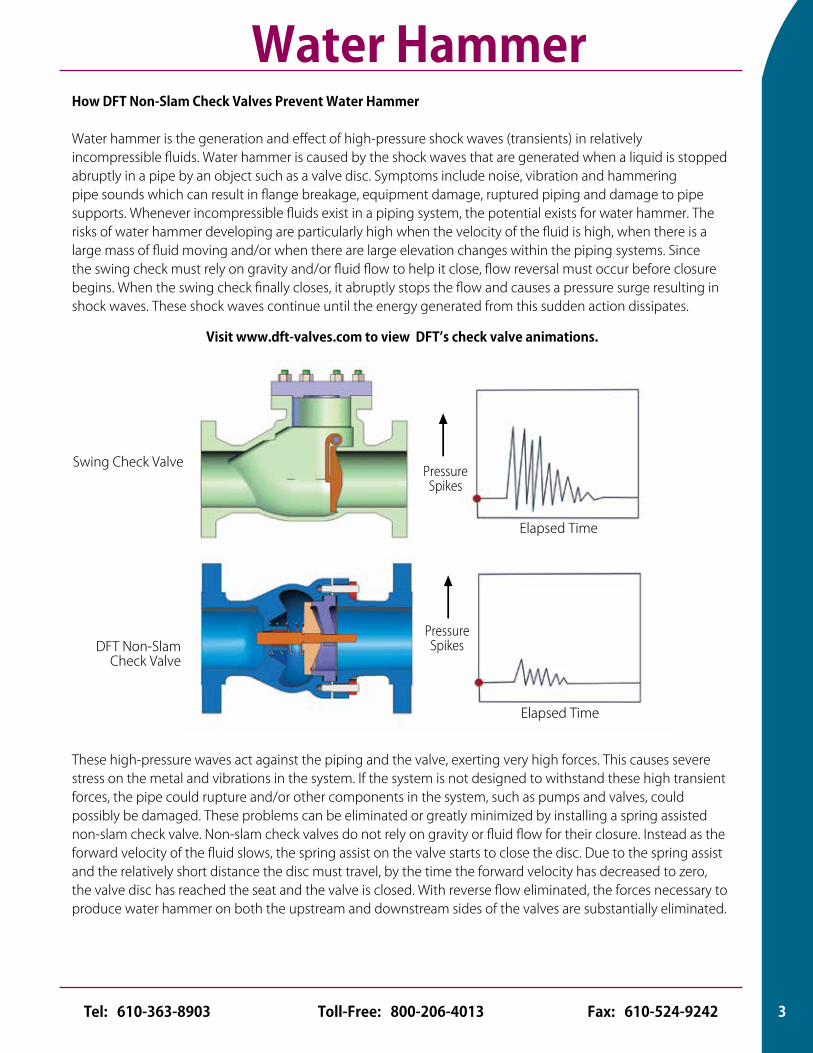
How DFT Non-Slam Check Valves Prevent Water Hammer
Water hammer is the generation and effect of high-pressure shock waves (transients) in relatively incompressible fluids. Water hammer is caused by the shock waves that are generated when a liquid is stopped abruptly in a pipe by an object such as a valve disc. Symptoms include noise, vibration and hammering pipe sounds which can result in flange breakage, equipment damage, ruptured piping and damage to pipe supports. Whenever incompressible fluids exist in a piping system, the potential exists for water hammer. The risks of water hammer developing are particularly high when the velocity of the fluid is high, when there is a large mass of fluid moving and/or when there are large elevation changes within the piping systems. Since the swing check must rely on gravity and/or fluid flow to help it close, flow reversal must occur before closure begins. When the swing check finally closes, it abruptly stops the flow and causes a pressure surge resulting in shock waves. These shock waves continue until the energy generated from this sudden action dissipates.
Water Hammer
These high-pressure waves act against the piping and the valve, exerting very high forces. This causes severe stress on the metal and vibrations in the system. If the system is not designed to withstand these high transient forces, the pipe could rupture and/or other components in the system, such as pumps and valves, could possibly be damaged. These problems can be eliminated or greatly minimized by installing a spring assisted non-slam check valve. Non-slam check valves do not rely on gravity or fluid flow for their closure. Instead as the forward velocity of the fluid slows, the spring assist on the valve starts to close the disc. Due to the spring assist and the relatively short distance the disc must travel, by the time the forward velocity has decreased to zero, the valve disc has reached the seat and the valve is closed. With reverse flow eliminated, the forces necessary to produce water hammer on both the upstream and downstream sides of the valves are substantially eliminated.
Swing Check Valve
DFT Non-Slam Check Valve
Pressure Spikes
Elapsed Time
#
#
Elapsed Time
Pressure Spikes
Visit www.dft-valves.com to view DFT’s check valve animations.
3Toll-Free: 800-206-4013 Fax: 610-524-9242Tel: 610-363-8903
Designed to prevent “Water Hammer.”The spring-assisted, axial flow, in-line, nozzle style, non-slam design featured in all DFT® check valves insures that as the forward flow in a pipeline decreases, the disc begins moving closer to the seat. By the time the flow stops, the disc is closed against the seat preventing flow reversal. This prevents the valve from slamming closed which can cause “Water Hammer” and the resultant noise and damage to piping systems.
Designed to open at approx. 0.5 psi differential pressure and fully open at 1.0 psi differential pressure. See product tables for specific cracking pressures.
Can be installed in ANY position.Including vertical with flow up or down. (Special springs may be required)
MSS SP 126-2000 Steel Non-slam Spring-Assisted Center Guided Check Valves Standard DFT carbon steel, stainless steel and alloy valves meet this standard. (Does not apply to the Basic-Check, Restrictor Check or Vacuum Breaker)
API 6D- Pipeline ValvesAPI 6D 24th edition specification holds hydrostatic and pneumatic testing to an elite new standard. Unlike the base API 598 testing, API 6D testing requires increased pressure testing durations, rust inhibitor, medium PH testing and more stringent design and manufacturing process controls. Contact DFT about products that meet API 6D.
API 6FD- Fire Test for Check ValvesASME Class 150 and 300 GLC meet API 6FD. (Line sizes 2-24”)
Meet or exceed MSS SP-61 leakage requirements. Metal-to-metal seating is standard in all DFT non-slam check valves. Cast iron valves meet AWWA seat leakage requirements. DFT’s standard test medium is water and meets or exceeds testing requirements.
Available with soft seats for bubble-tight shutoff. Soft seat material selected based on operating temperature and chemical compatibility. See page 42 for available options.
Dual-guided stems.The stem is guided upstream and downstream to guard against vibrations and insure proper disc seating. (Does not apply to the ALC®, Basic-Check®, DLC®, DSV® (1/2”-2”), Restrictor Check, SCV®, SCV-R® or Vacuum Breaker)
Custom sizing available.The following DFT check valves can be sized to the appropriate flow conditions: ALC®, Excalibur®, GLC®, WLC®, and Y-Calibur®.
Pulse-damping design.The DFT Model PDC® is specifically designed for use on the discharge of reciprocating air or gas compressors. The design includes a pulse-damping chamber to protect against premature seat wear due to chattering.
Liquids, gas or steam.All DFT non-slam check valves provide positive shutoff for applications involving liquids, gas or steam and can be used in most industries including oil and gas, petrochemical, pulp and paper, textiles, food and beverage and commercial construction. Applications include chemical lines, fluid injection, condensate recovery, steam, nitrogen, pump and compressor discharge, chiller and boiler feed systems. See page 47 for additional information.
NACEOptional body and trim materials to meet the NACE standards MR0103-2003 and MR0175/ISO 15156. See page 41.
Maintenance and Installation guides available for all DFT non-slam check valves.
Features
4 www.dft-valves.com [email protected]
Notes: 1. NPT x SW available.2. CWP RATING BSS, BSA, BSE, BSSV, Restrictor Check: 450 to 2500 CWP
depending on size; BSSH6, BSSV6: 450 to 6000 CWP depending on size. BSSH7: 800 to 6000 CWP depending on size. DSV: ASME/ANSI Class 108.
3. API 2000 and 5000 ARE AVAILABLE. Contact DFT for sizes.4. TRIM MATERIAL: BRONZE OR 316 SS
5. BODY & SEAT: BSE, BSS, BSSV. Restrictor Check: 303 SS, BSA: 416 SS, BSSH6, BSSH7, BSSV6: 316 SS, DSV:316L SS
6. Inconel® X-750 spring is standard.
* CF8M is the cast grade of 316 SS.
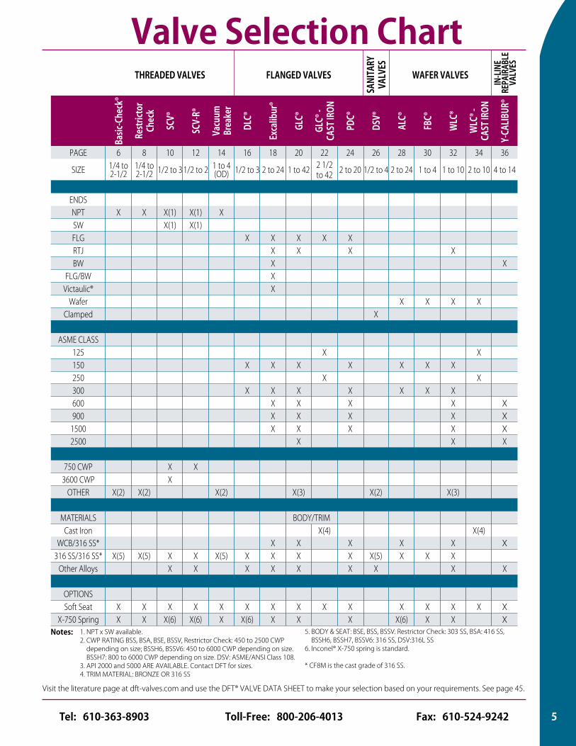
Valve Selection ChartTHREADED VALVES FLANGED VALVES
SANI
TARY
VA
LVES
WAFER VALVES
Basic
-Che
ck®
Restr
ictor
Ch
eck
SCV®
SCV-
R®
Vacu
um
Brea
ker
DLC®
Exca
libur
®
GLC®
GLC®
- CA
ST IR
ON
PDC®
DSV®
ALC®
FBC®
WLC
®
WLC
® -CA
ST IR
ON
Y-CA
LIBUR
®
PAGE 6 8 10 12 14 16 18 20 22 24 26 28 30 32 34 36
SIZE 1/4 to 2-1/2
1/4 to 2-1/2 1/2 to 3 1/2 to 2 1 to 4
(OD) 1/2 to 3 2 to 24 1 to 42 2 1/2 to 42 2 to 20 1/2 to 4 2 to 24 1 to 4 1 to 10 2 to 10 4 to 14
ENDSNPT X X X(1) X(1) XSW X(1) X(1)FLG X X X X XRTJ X X X XBW X X
FLG/BW XVictaulic® X
Wafer X X X XClamped X
ASME CLASS125 X X150 X X X X X X X250 X X300 X X X X X X X600 X X X X X900 X X X X X
1500 X X X X X2500 X X X
750 CWP X X3600 CWP X
OTHER X(2) X(2) X(2) X(3) X(2) X(3)
MATERIALS BODY/TRIMCast Iron X(4) X(4)
WCB/316 SS* X X X X X X316 SS/316 SS* X(5) X(5) X X X(5) X X X X X(5) X X X
Other Alloys X X X X X X X X X
OPTIONSSoft Seat X X X X X X X X X X X X X X X
X-750 Spring X X X(6) X(6) X X(6) X X X X(6) X X X
Visit the literature page at dft-valves.com and use the DFT® VALVE DATA SHEET to make your selection based on your requirements. See page 45.
IN-L
INE
REPA
IRAB
LEVA
LVES
5Toll-Free: 800-206-4013 Fax: 610-524-9242Tel: 610-363-8903
Consult pages 42 and 43 for Pressure/Temperature ratings and soft seat materials.
THRE
ADED
VAL
VES
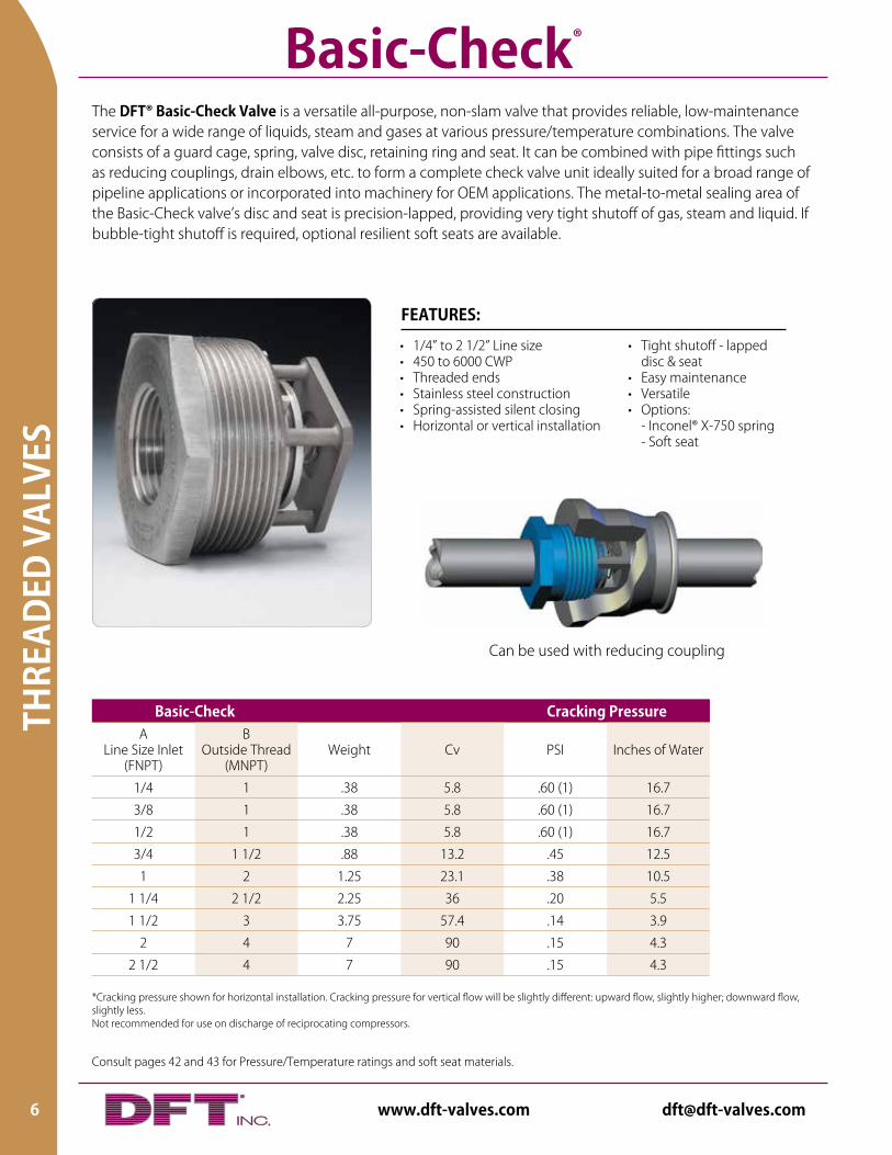
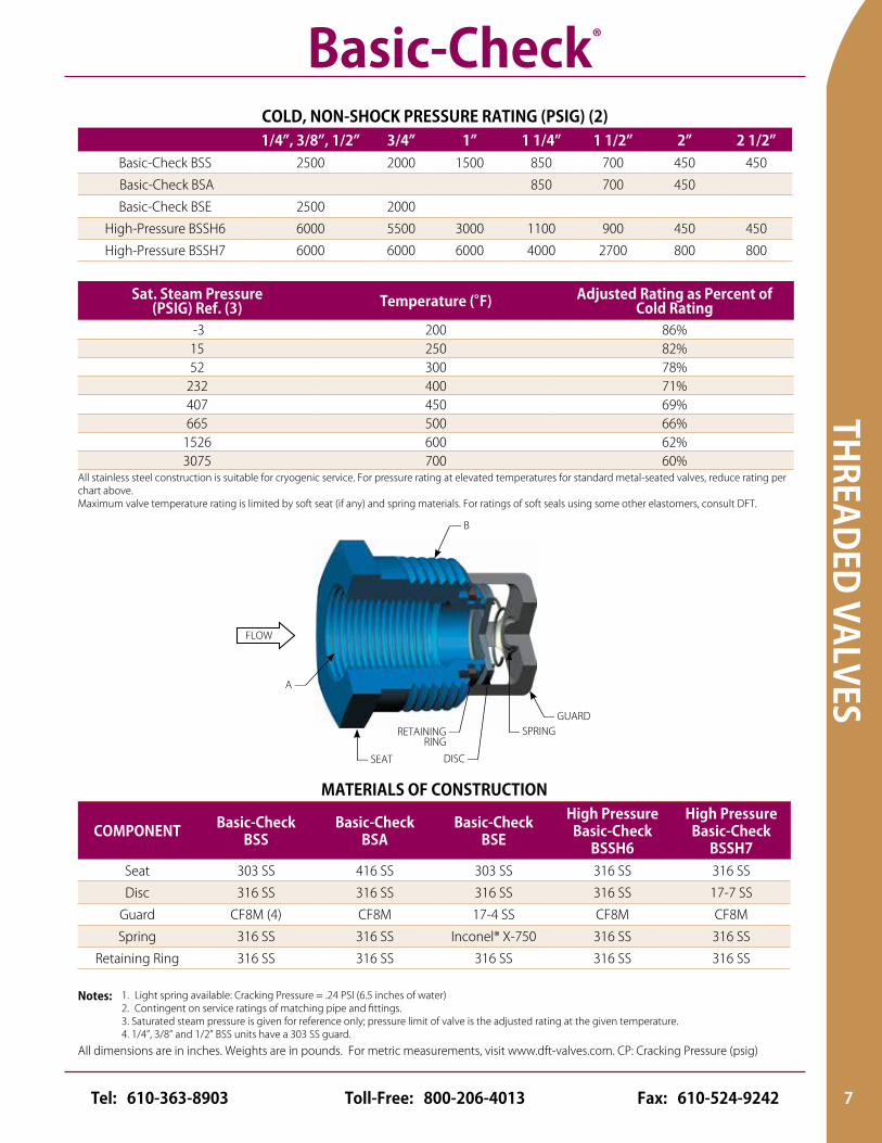
The DFT® Basic-Check Valve is a versatile all-purpose, non-slam valve that provides reliable, low-maintenance service for a wide range of liquids, steam and gases at various pressure/temperature combinations. The valve consists of a guard cage, spring, valve disc, retaining ring and seat. It can be combined with pipe fittings such as reducing couplings, drain elbows, etc. to form a complete check valve unit ideally suited for a broad range of pipeline applications or incorporated into machinery for OEM applications. The metal-to-metal sealing area of the Basic-Check valve’s disc and seat is precision-lapped, providing very tight shutoff of gas, steam and liquid. If bubble-tight shutoff is required, optional resilient soft seats are available.
Basic-Check Cracking PressureA
Line Size Inlet (FNPT)
B Outside Thread
(MNPT)Weight Cv PSI Inches of Water
1/4 1 .38 5.8 .60 (1) 16.7
3/8 1 .38 5.8 .60 (1) 16.7
1/2 1 .38 5.8 .60 (1) 16.7
3/4 1 1/2 .88 13.2 .45 12.5
1 2 1.25 23.1 .38 10.5
1 1/4 2 1/2 2.25 36 .20 5.5
1 1/2 3 3.75 57.4 .14 3.9
2 4 7 90 .15 4.3
2 1/2 4 7 90 .15 4.3
Basic-Check®
• 1/4” to 2 1/2” Line size• 450 to 6000 CWP• Threaded ends• Stainless steel construction• Spring-assisted silent closing• Horizontal or vertical installation
• Tight shutoff - lapped disc & seat• Easy maintenance• Versatile• Options: - Inconel® X-750 spring - Soft seat
FEATURES:
*Cracking pressure shown for horizontal installation. Cracking pressure for vertical flow will be slightly different: upward flow, slightly higher; downward flow, slightly less.Not recommended for use on discharge of reciprocating compressors.
Can be used with reducing coupling
6 www.dft-valves.com [email protected]
THREADED VALVES
All dimensions are in inches. Weights are in pounds. For metric measurements, visit www.dft-valves.com. CP: Cracking Pressure (psig)
All stainless steel construction is suitable for cryogenic service. For pressure rating at elevated temperatures for standard metal-seated valves, reduce rating per chart above.Maximum valve temperature rating is limited by soft seat (if any) and spring materials. For ratings of soft seals using some other elastomers, consult DFT.
COLD, NON-SHOCK PRESSURE RATING (PSIG) (2)1/4”, 3/8”, 1/2” 3/4” 1” 1 1/4” 1 1/2” 2” 2 1/2”
Basic-Check BSS 2500 2000 1500 850 700 450 450
Basic-Check BSA 850 700 450
Basic-Check BSE 2500 2000
High-Pressure BSSH6 6000 5500 3000 1100 900 450 450
High-Pressure BSSH7 6000 6000 6000 4000 2700 800 800
Sat. Steam Pressure (PSIG) Ref. (3) Temperature (°F) Adjusted Rating as Percent of
Cold Rating -3 200 86%15 250 82%52 300 78%
232 400 71%407 450 69%665 500 66%
1526 600 62%3075 700 60%
MATERIALS OF CONSTRUCTION
COMPONENT Basic-Check BSS
Basic-Check BSA
Basic-Check BSE
High Pressure Basic-Check
BSSH6
High Pressure Basic-Check
BSSH7Seat 303 SS 416 SS 303 SS 316 SS 316 SS
Disc 316 SS 316 SS 316 SS 316 SS 17-7 SS
Guard CF8M (4) CF8M 17-4 SS CF8M CF8M
Spring 316 SS 316 SS Inconel® X-750 316 SS 316 SS
Retaining Ring 316 SS 316 SS 316 SS 316 SS 316 SS
1. Light spring available: Cracking Pressure = .24 PSI (6.5 inches of water)2. Contingent on service ratings of matching pipe and fittings.3. Saturated steam pressure is given for reference only; pressure limit of valve is the adjusted rating at the given temperature. 4. 1/4”, 3/8” and 1/2” BSS units have a 303 SS guard.
Notes:
Basic-Check®
FLOW
— B
— GUARD— SPRING
DISC —
RETAINING — RING
— SEAT
A —
7Toll-Free: 800-206-4013 Fax: 610-524-9242Tel: 610-363-8903
Consult pages 42 and 43 for Pressure/Temperature ratings and soft seat materials.
THRE
ADED
VAL
VES
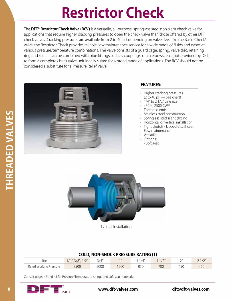
COLD, NON-SHOCK PRESSURE RATING (1)Size 1/4”, 3/8”, 1/2” 3/4” 1” 1 1/4” 1 1/2” 2” 2 1/2”
Rated Working Pressure 2500 2000 1500 850 700 450 450
The DFT® Restrictor Check Valve (RCV) is a versatile, all-purpose, spring-assisted, non-slam check valve for applications that require higher cracking pressures to open the check valve than those offered by other DFT check valves. Cracking pressures are available from 2 to 40 psi depending on valve size. Like the Basic-Check® valve, the Restrictor Check provides reliable, low maintenance service for a wide range of fluids and gases at various pressure/temperature combinations. The valve consists of a guard cage, spring, valve disc, retaining ring and seat. It can be combined with pipe fittings such as couplings, drain elbows, etc. (not provided by DFT) to form a complete check valve unit ideally suited for a broad range of applications. The RCV should not be considered a substitute for a Pressure Relief Valve.
• Higher cracking pressures (2 to 40 psi — See chart)
• 1/4” to 2 1/2” Line size• 450 to 2500 CWP• Threaded ends• Stainless steel construction• Spring-assisted silent closing• Horizontal or vertical installation• Tight shutoff - lapped disc & seat• Easy maintenance• Versatile• Options: - Soft seat
FEATURES:
Restrictor Check
Typical Installation
8 www.dft-valves.com [email protected]
THREADED VALVES
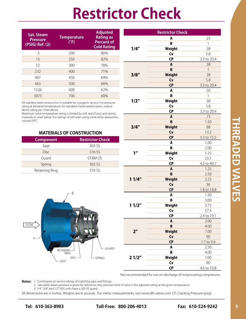
All dimensions are in inches. Weights are in pounds. For metric measurements, visit www.dft-valves.com. CP: Cracking Pressure (psig)
All stainless steel construction is suitable for cryogenic service. For pressure rating at elevated temperatures for standard metal-seated valves, reduce above rating per chart above.Maximum valve temperature rating is limited by soft seal (if any) and spring materials in chart below. For ratings of soft seals using some other elastomers, consult DFT.
MATERIALS OF CONSTRUCTIONComponent Restrictor Check
Seat 303 SS
Disc 316 SS
Guard CF8M (3)
Spring 302 SS
Retaining Ring 316 SS
Sat. Steam Pressure
(PSIG) Ref. (2)
Temperature (°F)
Adjusted Rating as
Percent of Cold Rating
-3 200 86%
15 250 82%
52 300 78%
232 400 71%
407 450 69%
665 500 66%
1526 600 62%
3075 700 60%
Not recommended for use on discharge of reciprocating compressors.
1. Contingent on service ratings of matching pipe and fittings.2. Saturated steam pressure is given for reference only; pressure limit of valve is the adjusted rating at the given temperature.3. 1/4”, 3/8” and 1/2” BSS units have a 303 SS guard.
Notes:
Restrictor Check
FLOW
— B
DISC — — SPRING
— GUARD
A —
— SEAT
RETAINING — RING
Restrictor Check
1/4”
A .25B 1
Weight .38Cv 5.8CP 3.3 to 20.4
3/8”
A .38B 1
Weight .38Cv 5.8CP 3.3 to 20.4
1/2”
A .50B 1
Weight .38Cv 5.8CP 3.3 to 20.4
3/4”
A .75B 1.50
Weight .88Cv 13.2CP 3.3 to 15.5
1”
A 1.00B 2.00
Weight 1.25Cv 23.1CP 4.2 to 40.7
1 1/4”
A 1.25B 2.50
Weight 2.25Cv 36CP 1.8 to 18.8
1 1/2”
A 1.50B 3.00
Weight 3.75Cv 57.4CP 2.4 to 19.1
2”
A 2.00B 4.00
Weight 7.00Cv 90CP 1.7 to 9.4
2 1/2”
A 2.50B 4.00
Weight 7.00Cv 90CP 4.6 to 10.8
9Toll-Free: 800-206-4013 Fax: 610-524-9242Tel: 610-363-8903
Consult pages 42 and 43 for Pressure/Temperature ratings and soft seat materials.
THRE
ADED
VAL
VES
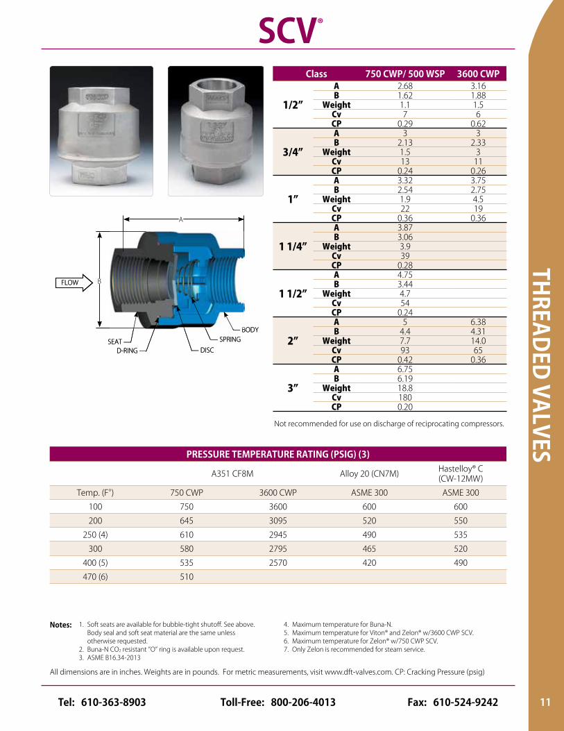
MATERIALS OF CONSTRUCTIONCOMPONENT 750 CWP 3600 CWP
Body A351 CF8M A351 CF8MSeat (1) A351 CF8M A351 CF8M
Disc A240 316 A240 316Spring Inconel® X-750 Inconel® X-750
Body Seal (7) Standard: Zelon (470°F max.) Standard: Zelon (400°F max.)(2)Option: Body seal weld (700°F max.) Option: Body seal weld (700°F max.)
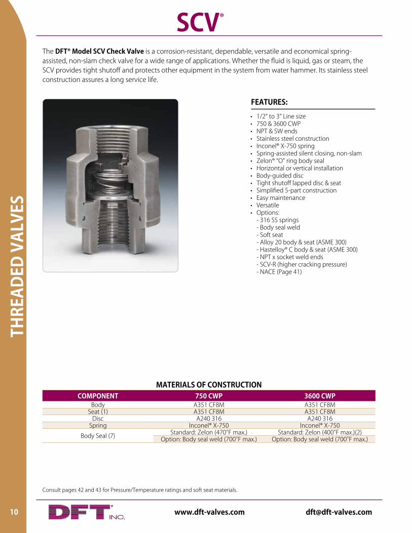
The DFT® Model SCV Check Valve is a corrosion-resistant, dependable, versatile and economical spring-assisted, non-slam check valve for a wide range of applications. Whether the fluid is liquid, gas or steam, the SCV provides tight shutoff and protects other equipment in the system from water hammer. Its stainless steel construction assures a long service life.
• 1/2” to 3” Line size• 750 & 3600 CWP• NPT & SW ends• Stainless steel construction• Inconel® X-750 spring• Spring-assisted silent closing, non-slam• Zelon® “O” ring body seal• Horizontal or vertical installation• Body-guided disc• Tight shutoff lapped disc & seat• Simplified 5-part construction • Easy maintenance • Versatile• Options: - 316 SS springs - Body seal weld - Soft seat - Alloy 20 body & seat (ASME 300) - Hastelloy® C body & seat (ASME 300) - NPT x socket weld ends - SCV-R (higher cracking pressure) - NACE (Page 41)
FEATURES:
SCV®
10 www.dft-valves.com [email protected]
THREADED VALVES
All dimensions are in inches. Weights are in pounds. For metric measurements, visit www.dft-valves.com. CP: Cracking Pressure (psig)
SCV®
FLOW
D-RING — — DISC
— SPRING— BODY
SEAT —
A
BFLOW
D-RING — — DISC
— SPRINGSEAT —
A
B
— BODY
Class 750 CWP/ 500 WSP 3600 CWP
1/2”
A 2.68 3.16B 1.62 1.88
Weight 1.1 1.5Cv 7 6CP 0.29 0.62
3/4”
A 3 3B 2.13 2.33
Weight 1.5 3Cv 13 11CP 0.24 0.26
1”
A 3.32 3.75B 2.54 2.75
Weight 1.9 4.5Cv 22 19CP 0.36 0.36
1 1/4”
A 3.87B 3.06
Weight 3.9Cv 39CP 0.28
1 1/2”
A 4.75B 3.44
Weight 4.7Cv 54CP 0.24
2”
A 5 6.38B 4.4 4.31
Weight 7.7 14.0Cv 93 65CP 0.42 0.36
3”
A 6.75B 6.19
Weight 18.8Cv 180CP 0.20
PRESSURE TEMPERATURE RATING (PSIG) (3)
A351 CF8M Alloy 20 (CN7M) Hastelloy® C (CW-12MW)
Temp. (F°) 750 CWP 3600 CWP ASME 300 ASME 300
100 750 3600 600 600
200 645 3095 520 550
250 (4) 610 2945 490 535
300 580 2795 465 520
400 (5) 535 2570 420 490
470 (6) 510
1. Soft seats are available for bubble-tight shutoff. See above. Body seal and soft seat material are the same unless otherwise requested.2. Buna-N CO2 resistant ”O” ring is available upon request.3. ASME B16.34-2013
Notes: 4. Maximum temperature for Buna-N. 5. Maximum temperature for Viton® and Zelon® w/3600 CWP SCV.6. Maximum temperature for Zelon® w/750 CWP SCV.7. Only Zelon is recommended for steam service.
Not recommended for use on discharge of reciprocating compressors.
11Toll-Free: 800-206-4013 Fax: 610-524-9242Tel: 610-363-8903
Consult pages 42 and 43 for Pressure/Temperature ratings and soft seat materials.
THRE
ADED
VAL
VES
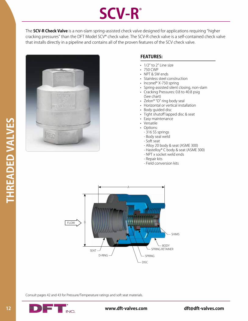
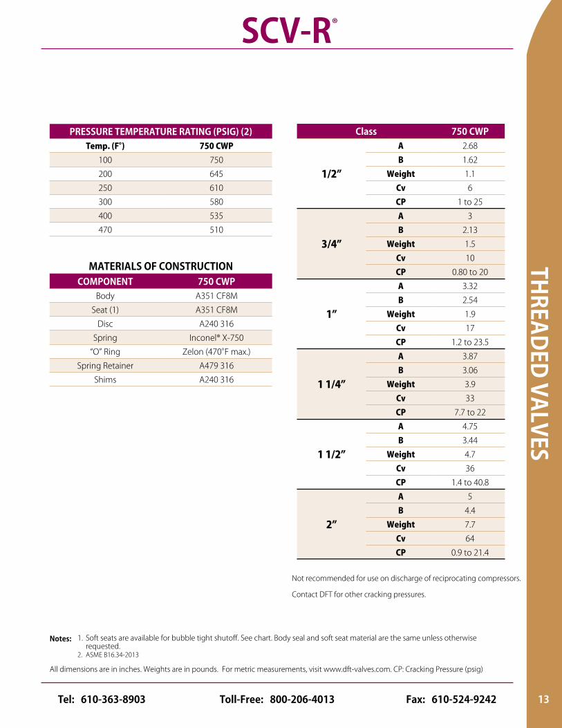
The SCV-R Check Valve is a non-slam spring-assisted check valve designed for applications requiring “higher cracking pressures” than the DFT Model SCV® check valve. The SCV-R check valve is a self-contained check valve that installs directly in a pipeline and contains all of the proven features of the SCV check valve.
• 1/2” to 2” Line size• 750 CWP• NPT & SW ends• Stainless steel construction• Inconel® X-750 spring• Spring-assisted silent closing, non-slam• Cracking Pressures: 0.8 to 40.8 psig (See chart)• Zelon® “O” ring body seal• Horizontal or vertical installation• Body guided disc• Tight shutoff lapped disc & seat• Easy maintenance• Versatile• Options: - 316 SS springs - Body seal weld - Soft seat - Alloy 20 body & seat (ASME 300) - Hastelloy® C body & seat (ASME 300) - NPT x socket weld ends - Repair kits - Field conversion kits
FEATURES:
SCV-R®
FLOW B
— DISC
— BODY
A
— SHIMS
SEAT —
D-RING — — SPRING
— SPRING RETAINER
12 www.dft-valves.com [email protected]
THREADED VALVES
All dimensions are in inches. Weights are in pounds. For metric measurements, visit www.dft-valves.com. CP: Cracking Pressure (psig)
Contact DFT for other cracking pressures.
Class 750 CWP
1/2”
A 2.68
B 1.62
Weight 1.1
Cv 6
CP 1 to 25
3/4”
A 3
B 2.13
Weight 1.5
Cv 10
CP 0.80 to 20
1”
A 3.32
B 2.54
Weight 1.9
Cv 17
CP 1.2 to 23.5
1 1/4”
A 3.87
B 3.06
Weight 3.9
Cv 33
CP 7.7 to 22
1 1/2”
A 4.75
B 3.44
Weight 4.7
Cv 36
CP 1.4 to 40.8
2”
A 5
B 4.4
Weight 7.7
Cv 64
CP 0.9 to 21.4
MATERIALS OF CONSTRUCTIONCOMPONENT 750 CWP
Body A351 CF8M
Seat (1) A351 CF8M
Disc A240 316
Spring Inconel® X-750
“O” Ring Zelon (470°F max.)
Spring Retainer A479 316
Shims A240 316
PRESSURE TEMPERATURE RATING (PSIG) (2)Temp. (F°) 750 CWP
100 750
200 645
250 610
300 580
400 535
470 510
1. Soft seats are available for bubble tight shutoff. See chart. Body seal and soft seat material are the same unless otherwise requested.2. ASME B16.34-2013
Notes:
SCV-R®
Not recommended for use on discharge of reciprocating compressors.
13Toll-Free: 800-206-4013 Fax: 610-524-9242Tel: 610-363-8903
Consult pages 42 and 43 for Pressure/Temperature ratings and soft seat materials.
THRE
ADED
VAL
VES
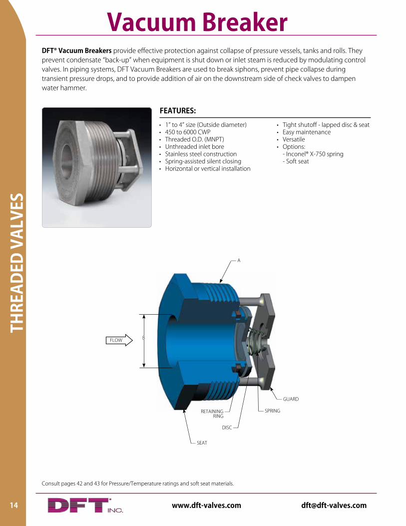
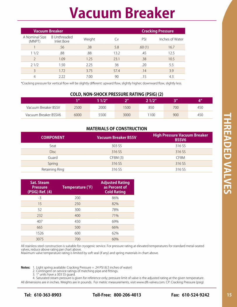
DFT® Vacuum Breakers provide effective protection against collapse of pressure vessels, tanks and rolls. They prevent condensate “back-up” when equipment is shut down or inlet steam is reduced by modulating control valves. In piping systems, DFT Vacuum Breakers are used to break siphons, prevent pipe collapse during transient pressure drops, and to provide addition of air on the downstream side of check valves to dampen water hammer.
Vacuum Breaker
• Tight shutoff - lapped disc & seat• Easy maintenance• Versatile• Options: - Inconel® X-750 spring - Soft seat
• 1” to 4” size (Outside diameter)• 450 to 6000 CWP• Threaded O.D. (MNPT)• Unthreaded inlet bore• Stainless steel construction• Spring-assisted silent closing• Horizontal or vertical installation
FEATURES:
FLOW B
— GUARD
— SPRING
DISC —
— SEAT
— A
RETAINING — RING
14 www.dft-valves.com [email protected]
THREADED VALVES
All dimensions are in inches. Weights are in pounds. For metric measurements, visit www.dft-valves.com. CP: Cracking Pressure (psig)
Vacuum Breaker Cracking PressureA Nominal Size
(MNPT)B Unthreaded
Inlet Bore Weight Cv PSI Inches of Water
1 .56 .38 5.8 .60 (1) 16.7
1 1/2 .88 .88 13.2 .45 12.5
2 1.09 1.25 23.1 .38 10.5
2 1/2 1.50 2.25 36 .20 5.5
3 1.72 3.75 57.4 .14 3.9
4 2.22 7.00 90 .15 4.3
*Cracking pressure for vertical flow will be slightly different: upward flow, slightly higher; downward flow, slightly less.
COLD, NON-SHOCK PRESSURE RATING (PSIG) (2)1” 1 1/2” 2” 2 1/2” 3” 4”
Vacuum Breaker BSSV 2500 2000 1500 850 700 450
Vacuum Breaker BSSV6 6000 5500 3000 1100 900 450
Sat. Steam Pressure
(PSIG) Ref. (4)Temperature (°F)
Adjusted Rating as Percent of Cold Rating
-3 200 86%
15 250 82%
52 300 78%
232 400 71%
407 450 69%
665 500 66%
1526 600 62%
3075 700 60%
All stainless steel construction is suitable for cryogenic service. For pressure rating at elevated temperatures for standard metal-seated valves, reduce above rating per chart above.Maximum valve temperature rating is limited by soft seal (if any) and spring materials in chart above.
1. Light spring available: Cracking Pressure = .24 PSI (6.5 inches of water)2. Contingent on service ratings of matching pipe and fittings.3. 1” units have a 303 SS guard.4. Saturated steam pressure is given for reference only; pressure limit of valve is the adjusted rating at the given temperature.
Notes:
Vacuum Breaker
MATERIALS OF CONSTRUCTION
COMPONENT Vacuum Breaker BSSV High Pressure Vacuum Breaker BSSV6
Seat 303 SS 316 SS
Disc 316 SS 316 SS
Guard CF8M (3) CF8M
Spring 316 SS 316 SS
Retaining Ring 316 SS 316 SS
15Toll-Free: 800-206-4013 Fax: 610-524-9242Tel: 610-363-8903
FLAN
GED
VALV
ES
16 www.dft-valves.com [email protected]
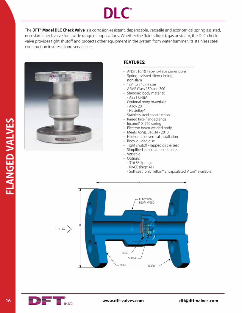
The DFT® Model DLC Check Valve is a corrosion-resistant, dependable, versatile and economical spring assisted, non-slam check valve for a wide range of applications. Whether the fluid is liquid, gas or steam, the DLC check valve provides tight shutoff and protects other equipment in the system from water hammer. Its stainless steel construction insures a long service life.
• ANSI B16.10 Face-to-Face dimensions• Spring-assisted silent closing, non-slam• 1/2” to 3” Line size• ASME Class 150 and 300• Standard body material: - A351 CF8M• Optional body materials: - Alloy 20 - Hastelloy®• Stainless steel construction• Raised face flanged ends• Inconel® X-750 spring• Electron beam welded body• Meets ASME B16.34 - 2013• Horizontal or vertical installation• Body-guided disc• Tight shutoff - lapped disc & seat• Simplified construction - 4 parts• Versatile• Options: - 316 SS Springs - NACE (Page 41) - Soft seat (only Teflon® Encapsulated Viton® available)
FEATURES:
DLC®
FLOWB
— ELECTRON BEAM WELD
SPRING —
DISC —
A
— SEAT BODY —

FLANGED VALVES
All dimensions are in inches. Weights are in pounds. For metric measurements, visit www.dft-valves.com. CP: Cracking Pressure (psig)
MATERIALS OF CONSTRUCTIONCOMPONENT
Body A351 CF8M
Seat A351 CF8M
Disc 316 SS
Spring Inconel® X-750
PRESSURE TEMPERATURE RATING (PSIG) (1)
A351 CF8M Alloy 20 (CN7M)
Hastelloy® C (CW-12MW)
Temp. (°F) ASME 150 ASME 300 Temp. (°F) ASME 150 ASME 300 ASME 150 ASME 300
-460 275 720 -325 230 600 230 600
100 275 720 100 230 600 230 600
200 235 620 200 200 520 210 550
300 215 560 300 180 465 200 520
400 195 515 400 160 420 190 490
500 170 480 500 150 390 170 465
600 140 450 600 140 360 140 440
700 110 435 700 110 420
Class 150 RF 300 RF
1/2”
A 4.25 6.00B 3.50 3.75
Weight 3.2 4.5Cv 7 7CP 0.29 0.29
3/4”
A 4.62 7.00B 3.88 4.62
Weight 4.5 7.2Cv 13 13CP 0.24 0.24
1”
A 5.00 8.50B 4.25 4.88
Weight 6.0 9.9Cv 22 22CP 0.36 0.36
1 1/2”
A 6.50 9.50B 5.00 6.12
Weight 11.7 18.5Cv 54 54CP 0.24 0.24
2”
A 8.00 10.50B 6.00 6.50
Weight 19.1 24.3Cv 93 93CP 0.42 0.23
3”
A 9.50 12.50B 7.50 8.25
Weight 39.2 50.5Cv 180 180CP 0.20 0.20
1. Pressure/temperature ratings in accordance with ASME/ANSI B16.34-2013. Notes:
DLC®
17Toll-Free: 800-206-4013 Fax: 610-524-9242Tel: 610-363-8903
Consult pages 42 and 43 for Pressure/Temperature ratings and soft seat materials.
FLAN
GED
VALV
ES
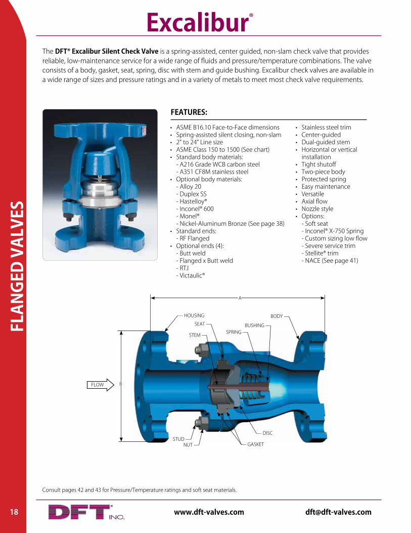
The DFT® Excalibur Silent Check Valve is a spring-assisted, center guided, non-slam check valve that provides reliable, low-maintenance service for a wide range of fluids and pressure/temperature combinations. The valve consists of a body, gasket, seat, spring, disc with stem and guide bushing. Excalibur check valves are available in a wide range of sizes and pressure ratings and in a variety of metals to meet most check valve requirements.
• Stainless steel trim • Center-guided• Dual-guided stem• Horizontal or vertical installation• Tight shutoff• Two-piece body• Protected spring• Easy maintenance• Versatile• Axial flow• Nozzle style• Options: - Soft seat - Inconel® X-750 Spring - Custom sizing low flow - Severe service trim - Stellite® trim - NACE (See page 41)
• ASME B16.10 Face-to-Face dimensions• Spring-assisted silent closing, non-slam• 2” to 24” Line size• ASME Class 150 to 1500 (See chart)• Standard body materials: - A216 Grade WCB carbon steel - A351 CF8M stainless steel• Optional body materials: - Alloy 20 - Duplex SS - Hastelloy® - Inconel® 600 - Monel® - Nickel-Aluminum Bronze (See page 38)• Standard ends: - RF Flanged• Optional ends (4): - Butt weld - Flanged x Butt weld - RTJ - Victaulic®
FEATURES:
Excalibur®
A
FLOW B
— DISC
SEAT —
STUD —
— HOUSING
STEM — SPRING —BUSHING —
BODY —
NUT — — GASKET
18 www.dft-valves.com [email protected]
FLANGED VALVES
All dimensions are in inches. Weights are in pounds. For metric measurements, visit www.dft-valves.com. CP: Cracking Pressure (psig)
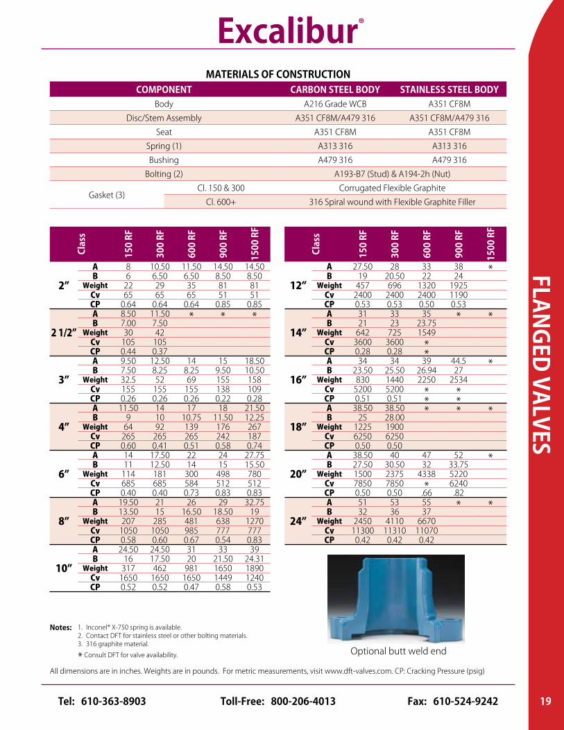
MATERIALS OF CONSTRUCTIONCOMPONENT CARBON STEEL BODY STAINLESS STEEL BODY
Body A216 Grade WCB A351 CF8M
Disc/Stem Assembly A351 CF8M/A479 316 A351 CF8M/A479 316
Seat A351 CF8M A351 CF8M
Spring (1) A313 316 A313 316
Bushing A479 316 A479 316
Bolting (2) A193-B7 (Stud) & A194-2h (Nut)
Gasket (3)Cl. 150 & 300 Corrugated Flexible Graphite
Cl. 600+ 316 Spiral wound with Flexible Graphite Filler
Clas
s
150
RF
300
RF
600
RF
900
RF
1500
RF
2”
A 8 10.50 11.50 14.50 14.50B 6 6.50 6.50 8.50 8.50
Weight 22 29 35 81 81Cv 65 65 65 51 51CP 0.64 0.64 0.64 0.85 0.85
2 1/2”
A 8.50 11.50 * * *B 7.00 7.50Weight 30 42
Cv 105 105CP 0.44 0.37
3”
A 9.50 12.50 14 15 18.50B 7.50 8.25 8.25 9.50 10.50
Weight 32.5 52 69 155 158Cv 155 155 155 138 109CP 0.26 0.26 0.26 0.22 0.28
4”
A 11.50 14 17 18 21.50B 9 10 10.75 11.50 12.25
Weight 64 92 139 176 267Cv 265 265 265 242 187CP 0.60 0.41 0.51 0.58 0.74
6”
A 14 17.50 22 24 27.75B 11 12.50 14 15 15.50
Weight 114 181 300 498 780Cv 685 685 584 512 512CP 0.40 0.40 0.73 0.83 0.83
8”
A 19.50 21 26 29 32.75B 13.50 15 16.50 18.50 19
Weight 207 285 481 638 1270Cv 1050 1050 985 777 777CP 0.58 0.60 0.67 0.54 0.83
10”
A 24.50 24.50 31 33 39B 16 17.50 20 21.50 24.31
Weight 317 462 981 1650 1890Cv 1650 1650 1650 1449 1240CP 0.52 0.52 0.47 0.58 0.53
Clas
s
150
RF
300
RF
600
RF
900
RF
1500
RF
12”
A 27.50 28 33 38 *B 19 20.50 22 24Weight 457 696 1320 1925
Cv 2400 2400 2400 1190CP 0.53 0.53 0.50 0.53
14”
A 31 33 35 * *B 21 23 23.75Weight 642 725 1549
Cv 3600 3600 *CP 0.28 0.28 *
16”
A 34 34 39 44.5 *B 23.50 25.50 26.94 27Weight 830 1440 2250 2534
Cv 5200 5200 * *CP 0.51 0.51 * *
18”
A 38.50 38.50 * * *B 25 28.00Weight 1225 1900
Cv 6250 6250CP 0.50 0.50
20”
A 38.50 40 47 52 *B 27.50 30.50 32 33.75Weight 1500 2375 4338 5220
Cv 7850 7850 * 6240CP 0.50 0.50 .66 .82
24”
A 51 53 55 * *B 32 36 37Weight 2450 4110 6670
Cv 11300 11310 11070CP 0.42 0.42 0.42
1. Inconel® X-750 spring is available.2. Contact DFT for stainless steel or other bolting materials.3. 316 graphite material.
* Consult DFT for valve availability.
Notes:
Excalibur®
Optional butt weld end
19Toll-Free: 800-206-4013 Fax: 610-524-9242Tel: 610-363-8903
Consult pages 42 and 43 for Pressure/Temperature ratings and soft seat materials.
FLAN
GED
VALV
ES
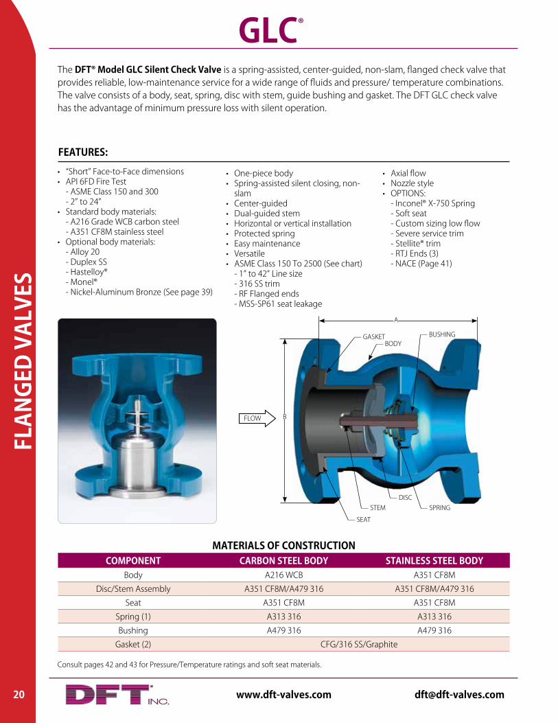
The DFT® Model GLC Silent Check Valve is a spring-assisted, center-guided, non-slam, flanged check valve that provides reliable, low-maintenance service for a wide range of fluids and pressure/ temperature combinations. The valve consists of a body, seat, spring, disc with stem, guide bushing and gasket. The DFT GLC check valve has the advantage of minimum pressure loss with silent operation.
GLC®
• “Short” Face-to-Face dimensions• API 6FD Fire Test - ASME Class 150 and 300 - 2” to 24”• Standard body materials: - A216 Grade WCB carbon steel - A351 CF8M stainless steel • Optional body materials: - Alloy 20 - Duplex SS - Hastelloy® - Monel® - Nickel-Aluminum Bronze (See page 39)
FEATURES:
• One-piece body• Spring-assisted silent closing, non-
slam• Center-guided• Dual-guided stem• Horizontal or vertical installation• Protected spring• Easy maintenance• Versatile• ASME Class 150 To 2500 (See chart) - 1” to 42” Line size - 316 SS trim - RF Flanged ends - MSS-SP61 seat leakage
• Axial flow• Nozzle style• OPTIONS: - Inconel® X-750 Spring - Soft seat - Custom sizing low flow - Severe service trim - Stellite® trim - RTJ Ends (3) - NACE (Page 41)
FLOW B
— GASKET
— SPRING— DISC
— SEAT
A
— STEM
— BODY— BUSHING
MATERIALS OF CONSTRUCTIONCOMPONENT CARBON STEEL BODY STAINLESS STEEL BODY
Body A216 WCB A351 CF8M
Disc/Stem Assembly A351 CF8M/A479 316 A351 CF8M/A479 316
Seat A351 CF8M A351 CF8M
Spring (1) A313 316 A313 316
Bushing A479 316 A479 316
Gasket (2) CFG/316 SS/Graphite
20 www.dft-valves.com [email protected]
FLANGED VALVES
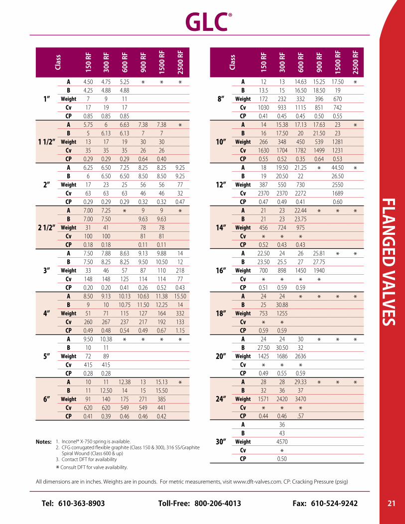
All dimensions are in inches. Weights are in pounds. For metric measurements, visit www.dft-valves.com. CP: Cracking Pressure (psig)
Clas
s
150
RF
300
RF
600
RF
900
RF
1500
RF
2500
RF
1”
A 4.50 4.75 5.25 * * *B 4.25 4.88 4.88
Weight 7 9 11Cv 17 19 17CP 0.85 0.85 0.85
1 1/2”
A 5.75 6 6.63 7.38 7.38 *B 5 6.13 6.13 7 7
Weight 13 17 19 30 30Cv 35 35 35 26 26CP 0.29 0.29 0.29 0.64 0.40
2”
A 6.25 6.50 7.25 8.25 8.25 9.25B 6 6.50 6.50 8.50 8.50 9.25
Weight 17 23 25 56 56 77Cv 63 63 63 46 46 32CP 0.29 0.29 0.29 0.32 0.32 0.47
2 1/2”
A 7.00 7.25 * 9 9 *B 7.00 7.50 9.63 9.63
Weight 31 41 78 78Cv 100 100 81 81CP 0.18 0.18 0.11 0.11
3”
A 7.50 7.88 8.63 9.13 9.88 14B 7.50 8.25 8.25 9.50 10.50 12
Weight 33 46 57 87 110 218Cv 148 148 125 114 114 77CP 0.20 0.20 0.41 0.26 0.52 0.43
4”
A 8.50 9.13 10.13 10.63 11.38 15.50B 9 10 10.75 11.50 12.25 14
Weight 51 71 115 127 164 332Cv 260 267 237 217 192 133CP 0.49 0.48 0.54 0.49 0.67 1.15
5”
A 9.50 10.38 * * * *B 10 11
Weight 72 89Cv 415 415CP 0.28 0.28
6”
A 10 11 12.38 13 15.13 *B 11 12.50 14 15 15.50
Weight 91 140 175 271 385Cv 620 620 549 549 441CP 0.41 0.39 0.46 0.46 0.42
Clas
s
150
RF
300
RF
600
RF
900
RF
1500
RF
2500
RF
8”
A 12 13 14.63 15.25 17.50 *B 13.5 15 16.50 18.50 19
Weight 172 232 332 396 670Cv 1030 933 1115 851 742CP 0.41 0.45 0.45 0.50 0.55
10”
A 14 15.38 17.13 17.63 23 *B 16 17.50 20 21.50 23
Weight 266 348 450 539 1281Cv 1630 1704 1782 1499 1231CP 0.55 0.52 0.35 0.64 0.53
12”
A 18 19.50 21.25 * 44.50 *B 19 20.50 22 26.50
Weight 387 550 730 2550Cv 2370 2370 2272 1689CP 0.47 0.49 0.41 0.60
14”
A 21 23 22.44 * * *B 21 23 23.75
Weight 456 724 975Cv * * *CP 0.52 0.43 0.43
16”
A 22.50 24 26 25.81 * *B 23.50 25.5 27 27.75
Weight 700 898 1450 1940Cv * * * *CP 0.51 0.59 0.59
18”
A 24 24 * * * *B 25 30.88
Weight 753 1255Cv * *CP 0.59 0.59
20”
A 24 24 30 * * *B 27.50 30.50 32
Weight 1425 1686 2636Cv * * *CP 0.49 0.55 0.59
24”
A 28 28 29.33 * * *B 32 36 37
Weight 1571 2420 3470Cv * * *CP 0.44 0.46 .57
30”
A 36B 43
Weight 4570Cv *CP 0.50
1. Inconel® X-750 spring is available.2. CFG corrugated flexible graphite (Class 150 & 300), 316 SS/Graphite Spiral Wound (Class 600 & up)3. Contact DFT for availability
* Consult DFT for valve availability.
Notes:
GLC®
21Toll-Free: 800-206-4013 Fax: 610-524-9242Tel: 610-363-8903
Consult pages 42 and 43 for Pressure/Temperature ratings and soft seat materials.
FLAN
GED
VALV
ES
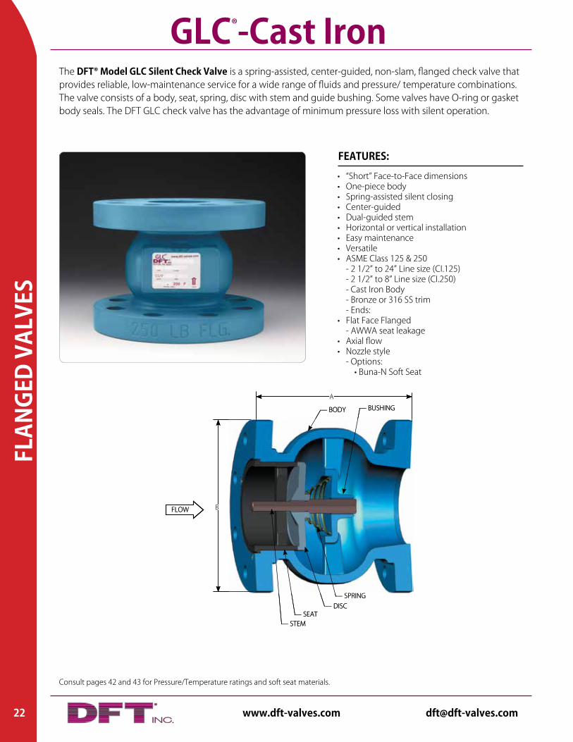
The DFT® Model GLC Silent Check Valve is a spring-assisted, center-guided, non-slam, flanged check valve that provides reliable, low-maintenance service for a wide range of fluids and pressure/ temperature combinations. The valve consists of a body, seat, spring, disc with stem and guide bushing. Some valves have O-ring or gasket body seals. The DFT GLC check valve has the advantage of minimum pressure loss with silent operation.
GLC®-Cast Iron
• “Short” Face-to-Face dimensions• One-piece body• Spring-assisted silent closing• Center-guided• Dual-guided stem• Horizontal or vertical installation• Easy maintenance• Versatile• ASME Class 125 & 250 - 2 1/2” to 24” Line size (CI.125) - 2 1/2” to 8” Line size (CI.250) - Cast Iron Body - Bronze or 316 SS trim - Ends:• Flat Face Flanged - AWWA seat leakage• Axial flow• Nozzle style - Options: • Buna-N Soft Seat
FEATURES:
FLOW B
— STEM
— SPRING— DISC
— SEAT
— BUSHING
A
— BODY
FLOW B
— STEM
— SPRING— DISC
— SEAT
— BUSHING
A
— BODY
22 www.dft-valves.com [email protected]
FLANGED VALVES
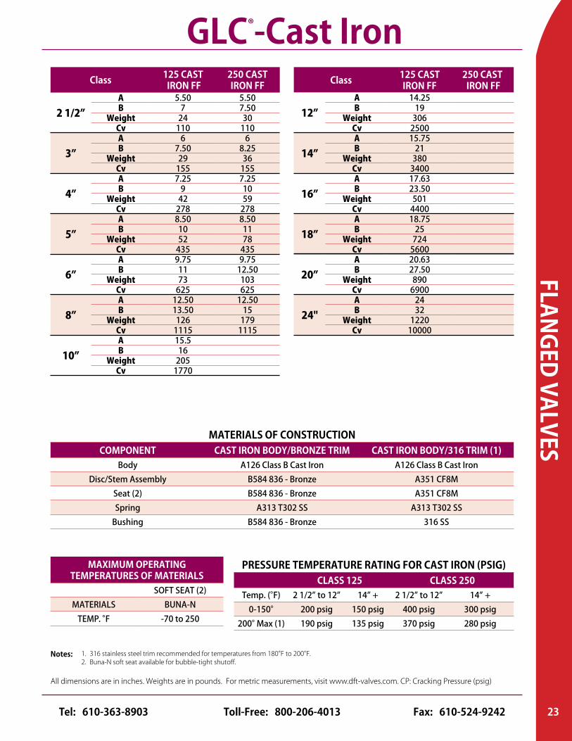
All dimensions are in inches. Weights are in pounds. For metric measurements, visit www.dft-valves.com. CP: Cracking Pressure (psig)
Class 125 CAST IRON FF
250 CAST IRON FF
2 1/2”A 5.50 5.50B 7 7.50
Weight 24 30Cv 110 110
3”A 6 6B 7.50 8.25
Weight 29 36Cv 155 155
4”A 7.25 7.25B 9 10
Weight 42 59Cv 278 278
5”A 8.50 8.50B 10 11
Weight 52 78Cv 435 435
6”A 9.75 9.75B 11 12.50
Weight 73 103Cv 625 625
8”A 12.50 12.50B 13.50 15
Weight 126 179Cv 1115 1115
10”A 15.5B 16
Weight 205Cv 1770
PRESSURE TEMPERATURE RATING FOR CAST IRON (PSIG)CLASS 125 CLASS 250
Temp. (°F) 2 1/2” to 12” 14” + 2 1/2” to 12” 14” +0-150° 200 psig 150 psig 400 psig 300 psig
200° Max (1) 190 psig 135 psig 370 psig 280 psig
MATERIALS OF CONSTRUCTIONCOMPONENT CAST IRON BODY/BRONZE TRIM CAST IRON BODY/316 TRIM (1)
Body A126 Class B Cast Iron A126 Class B Cast IronDisc/Stem Assembly B584 836 - Bronze A351 CF8M
Seat (2) B584 836 - Bronze A351 CF8MSpring A313 T302 SS A313 T302 SS
Bushing B584 836 - Bronze 316 SS
MAXIMUM OPERATING TEMPERATURES OF MATERIALS
SOFT SEAT (2)MATERIALS BUNA-N
TEMP. °F -70 to 250
1. 316 stainless steel trim recommended for temperatures from 180°F to 200°F.2. Buna-N soft seat available for bubble-tight shutoff.
Notes:
GLC®-Cast IronClass 125 CAST
IRON FF250 CAST IRON FF
12”A 14.25B 19
Weight 306Cv 2500
14”A 15.75B 21
Weight 380Cv 3400
16”A 17.63B 23.50
Weight 501Cv 4400
18”A 18.75B 25
Weight 724Cv 5600
20”A 20.63B 27.50
Weight 890Cv 6900
24"A 24B 32
Weight 1220Cv 10000
23Toll-Free: 800-206-4013 Fax: 610-524-9242Tel: 610-363-8903
Consult pages 42 and 43 for Pressure/Temperature ratings and soft seat materials.
FLAN
GED
VALV
ES
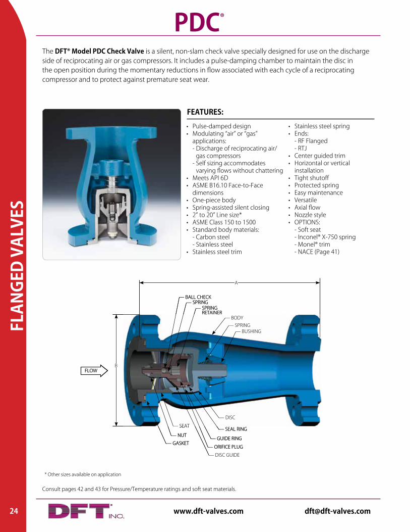
The DFT® Model PDC Check Valve is a silent, non-slam check valve specially designed for use on the discharge side of reciprocating air or gas compressors. It includes a pulse-damping chamber to maintain the disc in the open position during the momentary reductions in flow associated with each cycle of a reciprocating compressor and to protect against premature seat wear.
PDC®
• Pulse-damped design• Modulating “air” or “gas” applications: - Discharge of reciprocating air/
gas compressors - Self sizing accommodates
varying flows without chattering• Meets API 6D• ASME B16.10 Face-to-Face
dimensions• One-piece body• Spring-assisted silent closing• 2” to 20” Line size*• ASME Class 150 to 1500• Standard body materials: - Carbon steel - Stainless steel• Stainless steel trim
FEATURES:
• Stainless steel spring• Ends: - RF Flanged - RTJ• Center guided trim• Horizontal or vertical
installation• Tight shutoff• Protected spring• Easy maintenance• Versatile• Axial flow• Nozzle style• OPTIONS: - Soft seat - Inconel® X-750 spring - Monel® trim - NACE (Page 41)
FLOWB
— NUT
— SEAT
— BUSHING
A
— SEAL RING
— GASKET— ORIFICE PLUG
— GUIDE RING
— SPRING RETAINER
— DISC GUIDE
— BALL CHECK— SPRING
— BODY— SPRING
— DISC
FLOWB
— NUT
— SEAT
— BUSHING
A
— SEAL RING
— GASKET— ORIFICE PLUG
— GUIDE RING
— SPRING RETAINER
— DISC GUIDE
— BALL CHECK— SPRING
— BODY— SPRING
— DISC
* Other sizes available on application
24 www.dft-valves.com [email protected]
FLANGED VALVES
All dimensions are in inches. Weights are in pounds. For metric measurements, visit www.dft-valves.com. CP: Cracking Pressure (psig)
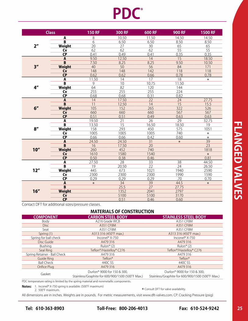
Class 150 RF 300 RF 600 RF 900 RF 1500 RF
2”
A 8 10.50 11.50 14.50 14.50B 6 6.50 6.50 8.50 8.50
Weight 20 27 30 65 65Cv 62 62 62 55 55CP 0.41 0.49 0.41 0.35 0.35
3”
A 9.50 12.50 14 15 18.50B 7.50 8.25 8.25 9.50 10.50
Weight 40 50 56 84 171Cv 148 148 142 118 118CP 0.62 0.62 0.66 0.78 0.78
4”
A 11.50 14 17 18 *B 9 10 10.75 11.50Weight 64 82 120 144
Cv 255 255 255 224CP 0.68 0.68 0.31 0.82
6”
A 14 17.50 22 24 27.75B 11 12.50 14 15 15.5
Weight 105 152 265 322 526Cv 660 660 660 567 567CP 0.51 0.51 0.49 0.63 0.63
8”
A 19.50 21 26 29 32.75B 13.50 15 16.50 18.50 19
Weight 158 293 450 575 1051Cv 1005 1005 1005 740 *CP 0.66 0.66 0.42 0.60 *
10”
A 24.50 24.50 31 * 39B 16 17.50 20 23
Weight 260 452 740 1818Cv 1610 1580 1540 *CP 0.50 0.38 0.46 0.81
12”
A 27.50 28 33 38 44.50B 19 20.50 22 24 26.50
Weight 445 673 1021 1940 2590Cv 2300 2300 2300 1990 1590CP 0.29 0.29 0.29 .70 0.70
MATERIALS OF CONSTRUCTIONCOMPONENT CARBON STEEL BODY STAINLESS STEEL BODY
Body A216 Grade WCB A351 CF8MDisc A351 CF8M A351 CF8MSeat A351 CF8M A351 CF8M
Spring (1) A313 316 (450°F max.) A313 316 (450°F max.)Spring for ball check Inconel® X-750 Inconel® X-750
Disc Guide A479 316 A479 316Bushing Rulon® (2) Rulon® (2)Seal Ring Teflon®/Hastelloy® C276 Teflon®/Hastelloy® C276
Spring Retainer - Ball Check A479 316 A479 316Guide Ring Teflon® Teflon®Ball Check 440C SS 440C SS
Orifice Plug A479 316 A479 316
GasketDurlon® 9000 for 150 & 300,
Stainless/Graphite for 600/900/1500 (500°F Max.) Durlon® 9000 for 150 & 300,
Stainless/Graphite for 600/900/1500 (500°F Max.)PDC temperature rating is limited by the spring material and nonmetallic components.
1. Inconel® X-750 spring is available. (500°F maximum)2. 500°F maximum.
Notes:
PDC®
Contact DFT for additional sizes/pressure classes.
* Consult DFT for valve availability.
16”
A * 34 39 44.5 *B 25.5 27 27.75Weight 1352 2041 2797
Cv 5100 5100 3170CP 0.51 0.46 0.60
25Toll-Free: 800-206-4013 Fax: 610-524-9242Tel: 610-363-8903
Consult pages 42 and 43 for Pressure/Temperature ratings and soft seat materials.
SAN
ITAR
Y VA
LVES
Horizontal
1/2”
A 2.50B (Dia.) 1.50D (Dia.) .98Weight 1.4
C .44Cv 2.4CP .29
3/4”
A 2.50B 1.50
D (Dia.) .98Weight 1.4
C .31Cv 7CP .29
1”
A 3.48B (Dia.) 3.00D (Dia.) 1.98Weight 3.7
C .50Cv 12CP .36
1 1/2”
A 3.67B (Dia.) 3.12D (Dia.) 1.98Weight 4.0
C .50Cv 36CP .28
*Edge/Center Guided Disc
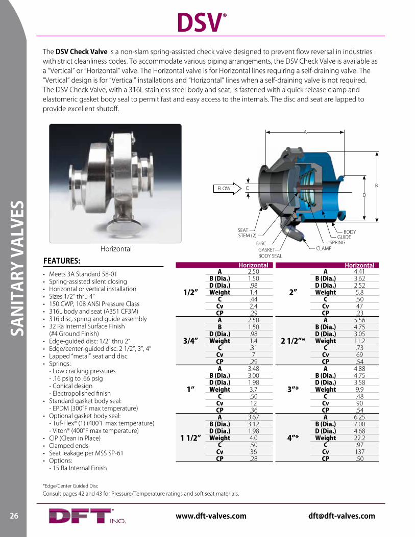
The DSV Check Valve is a non-slam spring-assisted check valve designed to prevent flow reversal in industries with strict cleanliness codes. To accommodate various piping arrangements, the DSV Check Valve is available as a “Vertical” or “Horizontal” valve. The Horizontal valve is for Horizontal lines requiring a self-draining valve. The “Vertical” design is for “Vertical” installations and “Horizontal” lines when a self-draining valve is not required. The DSV Check Valve, with a 316L stainless steel body and seat, is fastened with a quick release clamp and elastomeric gasket body seal to permit fast and easy access to the internals. The disc and seat are lapped to provide excellent shutoff.
DSV®
FEATURES: Horizontal
2”
A 4.41B (Dia.) 3.62D (Dia.) 2.52Weight 5.8
C .50Cv 47CP .23
2 1/2”*
A 5.56B (Dia.) 4.75D (Dia.) 3.05Weight 11.2
C .73Cv 69CP .54
3”*
A 4.88B (Dia.) 4.75D (Dia.) 3.58Weight 9.9
C .48Cv 90CP .54
4”*
A 6.25B (Dia.) 7.00D (Dia.) 4.68Weight 22.2
C .97Cv 137CP .50
Horizontal
FLOW B
D
A
C
SEAT —STEM (2) —
DISC — GASKET— BODY SEAL
— CLAMP— SPRING
— GUIDE— BODY
• Meets 3A Standard 58-01• Spring-assisted silent closing• Horizontal or vertical installation• Sizes 1/2” thru 4”• 150 CWP, 108 ANSI Pressure Class• 316L body and seat (A351 CF3M)• 316 disc, spring and guide assembly• 32 Ra Internal Surface Finish (#4 Ground Finish)• Edge-guided disc: 1/2” thru 2”• Edge/center-guided disc: 2 1/2”, 3”, 4”• Lapped “metal” seat and disc• Springs: - Low cracking pressures - .16 psig to .66 psig - Conical design - Electropolished finish• Standard gasket body seal: - EPDM (300°F max temperature)• Optional gasket body seal: - Tuf-Flex® (1) (400°F max temperature) - Viton® (400°F max temperature)• CIP (Clean in Place)• Clamped ends• Seat leakage per MSS SP-61• Options: - 15 Ra Internal Finish
26 www.dft-valves.com [email protected]
SANITARY VALVES
All dimensions are in inches. Weights are in pounds. For metric measurements, visit www.dft-valves.com. CP: Cracking Pressure (psig)
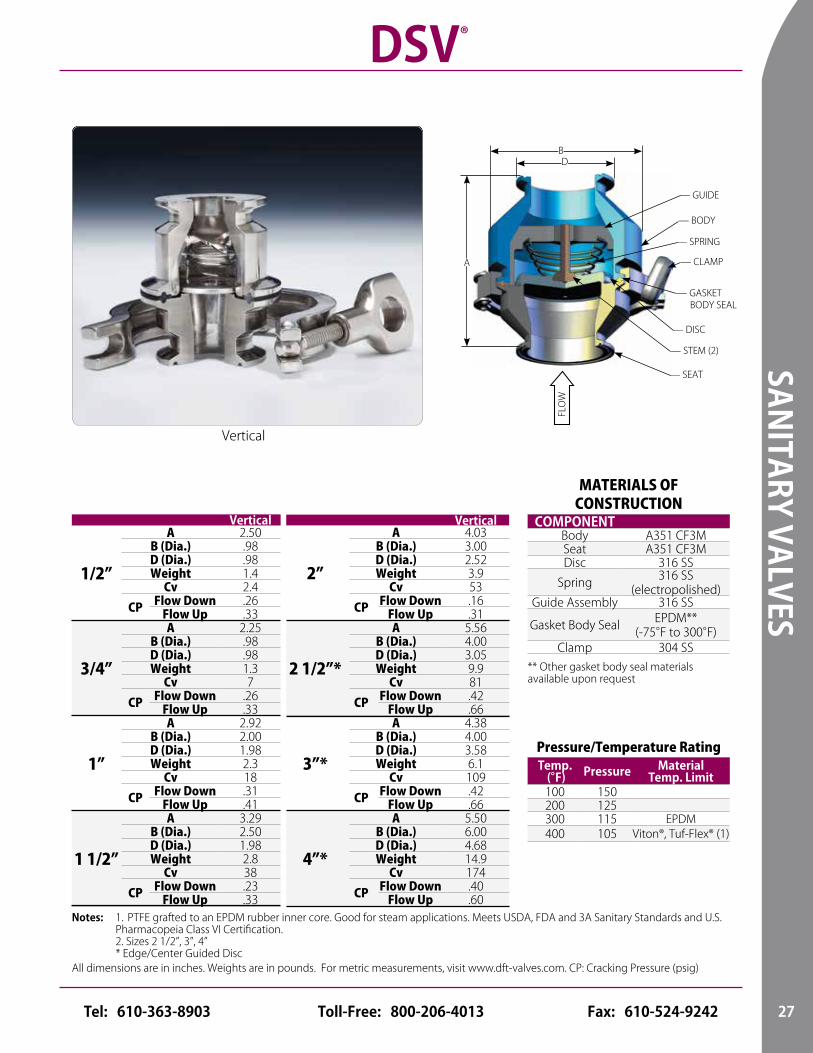
MATERIALS OF CONSTRUCTION
COMPONENTBody A351 CF3MSeat A351 CF3MDisc 316 SS
Spring 316 SS (electropolished)
Guide Assembly 316 SS
Gasket Body Seal EPDM** (-75°F to 300°F)
Clamp 304 SS** Other gasket body seal materials available upon request
Pressure/Temperature RatingTemp.
(°F) Pressure MaterialTemp. Limit
100 150200 125300 115 EPDM400 105 Viton®, Tuf-Flex® (1)
Vertical
1/2”
A 2.50B (Dia.) .98D (Dia.) .98Weight 1.4
Cv 2.4
CP Flow Down .26Flow Up .33
3/4”
A 2.25B (Dia.) .98D (Dia.) .98Weight 1.3
Cv 7
CP Flow Down .26Flow Up .33
1”
A 2.92B (Dia.) 2.00D (Dia.) 1.98Weight 2.3
Cv 18
CP Flow Down .31Flow Up .41
1 1/2”
A 3.29B (Dia.) 2.50D (Dia.) 1.98Weight 2.8
Cv 38
CP Flow Down .23Flow Up .33
1. PTFE grafted to an EPDM rubber inner core. Good for steam applications. Meets USDA, FDA and 3A Sanitary Standards and U.S. Pharmacopeia Class VI Certification.2. Sizes 2 1/2”, 3”, 4” * Edge/Center Guided Disc
Notes:
Vertical
2”
A 4.03B (Dia.) 3.00D (Dia.) 2.52Weight 3.9
Cv 53
CP Flow Down .16Flow Up .31
2 1/2”*
A 5.56B (Dia.) 4.00D (Dia.) 3.05Weight 9.9
Cv 81
CP Flow Down .42Flow Up .66
3”*
A 4.38B (Dia.) 4.00D (Dia.) 3.58Weight 6.1
Cv 109
CP Flow Down .42Flow Up .66
4”*
A 5.50B (Dia.) 6.00D (Dia.) 4.68Weight 14.9
Cv 174
CP Flow Down .40Flow Up .60
Vertical
DSV®
FLO
W
— STEM (2)
— CLAMP
— DISC
— SEAT
A
— GASKET BODY SEAL
BD
— GUIDE
— BODY
— SPRING
27Toll-Free: 800-206-4013 Fax: 610-524-9242Tel: 610-363-8903
Consult pages 42 and 43 for Pressure/Temperature ratings and soft seat materials.
WAF
ER V
ALVE
S
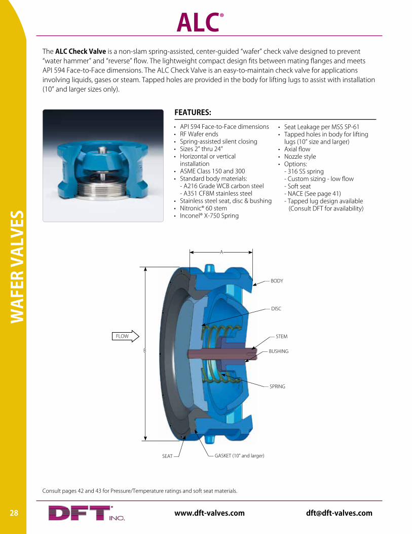
The ALC Check Valve is a non-slam spring-assisted, center-guided “wafer” check valve designed to prevent “water hammer” and “reverse” flow. The lightweight compact design fits between mating flanges and meets API 594 Face-to-Face dimensions. The ALC Check Valve is an easy-to-maintain check valve for applications involving liquids, gases or steam. Tapped holes are provided in the body for lifting lugs to assist with installation (10” and larger sizes only).
ALC®
• Seat Leakage per MSS SP-61• Tapped holes in body for lifting
lugs (10” size and larger)• Axial flow• Nozzle style• Options: - 316 SS spring - Custom sizing - low flow - Soft seat - NACE (See page 41) - Tapped lug design available (Consult DFT for availability)
• API 594 Face-to-Face dimensions• RF Wafer ends• Spring-assisted silent closing• Sizes 2” thru 24”• Horizontal or vertical
installation• ASME Class 150 and 300• Standard body materials: - A216 Grade WCB carbon steel - A351 CF8M stainless steel • Stainless steel seat, disc & bushing• Nitronic® 60 stem• Inconel® X-750 Spring
FEATURES:
FLOW — STEM
SEAT — — GASKET (10” and larger)
B
A
— SPRING
— BUSHING
— DISC
— BODY
28 www.dft-valves.com [email protected]
WAFER VALVES
All dimensions are in inches. Weights are in pounds. For metric measurements, visit www.dft-valves.com. CP: Cracking Pressure (psig)
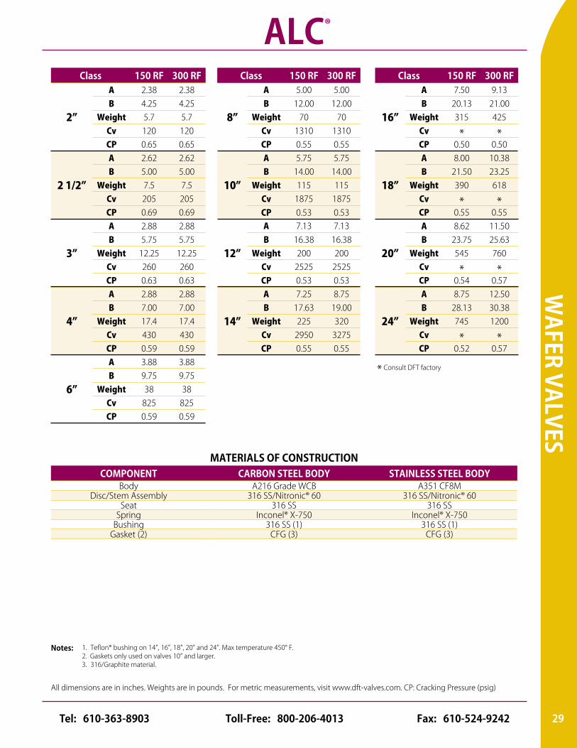
MATERIALS OF CONSTRUCTIONCOMPONENT CARBON STEEL BODY STAINLESS STEEL BODY
Body A216 Grade WCB A351 CF8MDisc/Stem Assembly 316 SS/Nitronic® 60 316 SS/Nitronic® 60
Seat 316 SS 316 SSSpring Inconel® X-750 Inconel® X-750
Bushing 316 SS (1) 316 SS (1)Gasket (2) CFG (3) CFG (3)
1. Teflon® bushing on 14”, 16”, 18”, 20” and 24”. Max temperature 450° F.2. Gaskets only used on valves 10” and larger. 3. 316/Graphite material.
Notes:
ALC®
Class 150 RF 300 RF
2”
A 2.38 2.38B 4.25 4.25
Weight 5.7 5.7Cv 120 120CP 0.65 0.65
2 1/2”
A 2.62 2.62B 5.00 5.00
Weight 7.5 7.5Cv 205 205CP 0.69 0.69
3”
A 2.88 2.88B 5.75 5.75
Weight 12.25 12.25Cv 260 260CP 0.63 0.63
4”
A 2.88 2.88B 7.00 7.00
Weight 17.4 17.4Cv 430 430CP 0.59 0.59
6”
A 3.88 3.88B 9.75 9.75
Weight 38 38Cv 825 825CP 0.59 0.59
Class 150 RF 300 RF
16”
A 7.50 9.13B 20.13 21.00
Weight 315 425Cv * *CP 0.50 0.50
18”
A 8.00 10.38B 21.50 23.25
Weight 390 618Cv * *CP 0.55 0.55
20”
A 8.62 11.50B 23.75 25.63
Weight 545 760Cv * *CP 0.54 0.57
24”
A 8.75 12.50B 28.13 30.38
Weight 745 1200Cv * *CP 0.52 0.57
Class 150 RF 300 RF
8”
A 5.00 5.00B 12.00 12.00
Weight 70 70Cv 1310 1310CP 0.55 0.55
10”
A 5.75 5.75B 14.00 14.00
Weight 115 115Cv 1875 1875CP 0.53 0.53
12”
A 7.13 7.13B 16.38 16.38
Weight 200 200Cv 2525 2525CP 0.53 0.53
14”
A 7.25 8.75B 17.63 19.00
Weight 225 320Cv 2950 3275CP 0.55 0.55
* Consult DFT factory
29Toll-Free: 800-206-4013 Fax: 610-524-9242Tel: 610-363-8903
Consult pages 42 and 43 for Pressure/Temperature ratings and soft seat materials.
WAF
ER V
ALVE
S
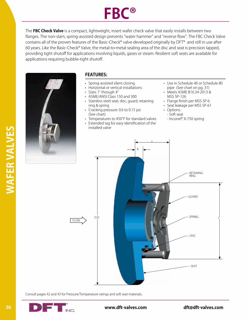
The FBC Check Valve is a compact, lightweight, insert wafer check valve that easily installs between two flanges. The non-slam, spring-assisted design prevents “water hammer” and “reverse flow”. The FBC Check Valve contains all of the proven features of the Basic-Check® valve developed originally by DFT® and still in use after 60 years. Like the Basic-Check® Valve, the metal-to-metal sealing area of the disc and seat is precision lapped, providing tight shutoff for applications involving liquids, gases or steam. Resilient soft seats are available for applications requiring bubble-tight shutoff.
FBC®
• Use in Schedule 40 or Schedule 80 pipe (See chart on pg. 31)• Meets ASME B16.34-2013 & MSS SP-126• Flange finish per MSS SP-6• Seat leakage per MSS SP-61• Options: - Soft seat - Inconel® X-750 spring
• Spring-assisted silent closing• Horizontal or vertical installations• Sizes 1” through 4”• ASME/ANSI Class 150 and 300• Stainless steel seat, disc, guard, retaining ring & spring• Cracking pressure: 0.6 to 0.15 psi (See chart)• Temperatures to 450°F for standard valves• Extended tag for easy identification of the installed valve
FEATURES:
FLOWO.D.
B
A
C
— SEAT
— DISC
— SPRING
— GUARD
— RETAINING RING
30 www.dft-valves.com [email protected]
WAFER VALVES
All dimensions are in inches. Weights are in pounds. For metric measurements, visit www.dft-valves.com. CP: Cracking Pressure (psig)
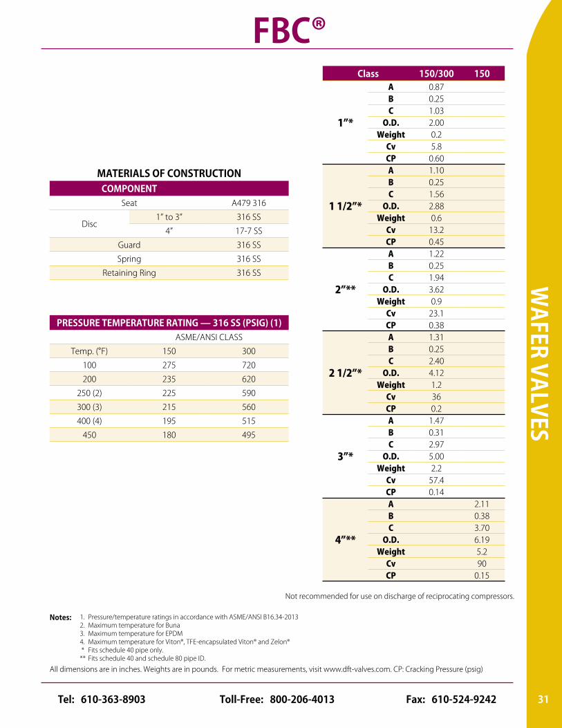
Class 150/300 150
1”*
A 0.87B 0.25C 1.03
O.D. 2.00Weight 0.2
Cv 5.8CP 0.60
1 1/2”*
A 1.10B 0.25C 1.56
O.D. 2.88Weight 0.6
Cv 13.2CP 0.45
2”**
A 1.22B 0.25C 1.94
O.D. 3.62Weight 0.9
Cv 23.1CP 0.38
2 1/2”*
A 1.31B 0.25C 2.40
O.D. 4.12Weight 1.2
Cv 36CP 0.2
3”*
A 1.47B 0.31C 2.97
O.D. 5.00Weight 2.2
Cv 57.4CP 0.14
4”**
A 2.11B 0.38C 3.70
O.D. 6.19Weight 5.2
Cv 90CP 0.15
MATERIALS OF CONSTRUCTIONCOMPONENT
Seat A479 316
Disc1” to 3” 316 SS
4” 17-7 SS
Guard 316 SS
Spring 316 SS
Retaining Ring 316 SS
1. Pressure/temperature ratings in accordance with ASME/ANSI B16.34-20132. Maximum temperature for Buna3. Maximum temperature for EPDM4. Maximum temperature for Viton®, TFE-encapsulated Viton® and Zelon® * Fits schedule 40 pipe only.** Fits schedule 40 and schedule 80 pipe ID.
Notes:
FBC®
PRESSURE TEMPERATURE RATING — 316 SS (PSIG) (1)ASME/ANSI CLASS
Temp. (°F) 150 300
100 275 720
200 235 620
250 (2) 225 590
300 (3) 215 560
400 (4) 195 515
450 180 495
Not recommended for use on discharge of reciprocating compressors.
31Toll-Free: 800-206-4013 Fax: 610-524-9242Tel: 610-363-8903
Consult pages 42 and 43 for Pressure/Temperature ratings and soft seat materials.
WAF
ER V
ALVE
S
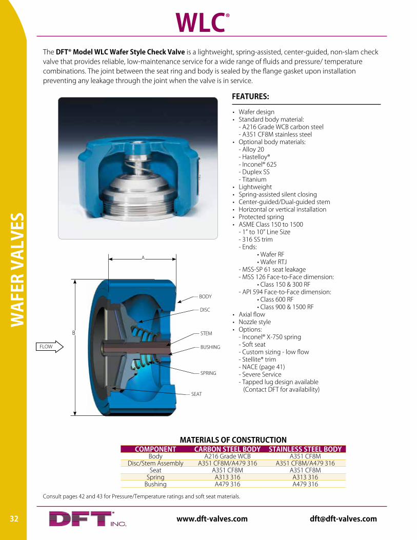
The DFT® Model WLC Wafer Style Check Valve is a lightweight, spring-assisted, center-guided, non-slam check valve that provides reliable, low-maintenance service for a wide range of fluids and pressure/ temperature combinations. The joint between the seat ring and body is sealed by the flange gasket upon installation preventing any leakage through the joint when the valve is in service.
WLC®
MATERIALS OF CONSTRUCTIONCOMPONENT CARBON STEEL BODY STAINLESS STEEL BODY
Body A216 Grade WCB A351 CF8MDisc/Stem Assembly A351 CF8M/A479 316 A351 CF8M/A479 316
Seat A351 CF8M A351 CF8MSpring A313 316 A313 316
Bushing A479 316 A479 316
• Wafer design• Standard body material: - A216 Grade WCB carbon steel - A351 CF8M stainless steel• Optional body materials: - Alloy 20 - Hastelloy® - Inconel® 625 - Duplex SS - Titanium• Lightweight• Spring-assisted silent closing• Center-guided/Dual-guided stem• Horizontal or vertical installation• Protected spring• ASME Class 150 to 1500 - 1” to 10” Line Size - 316 SS trim - Ends: • Wafer RF • Wafer RTJ - MSS-SP 61 seat leakage - MSS 126 Face-to-Face dimension: • Class 150 & 300 RF - API 594 Face-to-Face dimension: • Class 600 RF • Class 900 & 1500 RF• Axial flow• Nozzle style• Options: - Inconel® X-750 spring - Soft seat - Custom sizing - low flow - Stellite® trim - NACE (page 41) - Severe Service - Tapped lug design available (Contact DFT for availability)
FEATURES:
FLOW
— STEM
— BUSHING
— DISC
— SEAT
— BODY
— SPRING
A
B
32 www.dft-valves.com [email protected]
WAFER VALVES
All dimensions are in inches. Weights are in pounds. For metric measurements, visit www.dft-valves.com. CP: Cracking Pressure (psig)
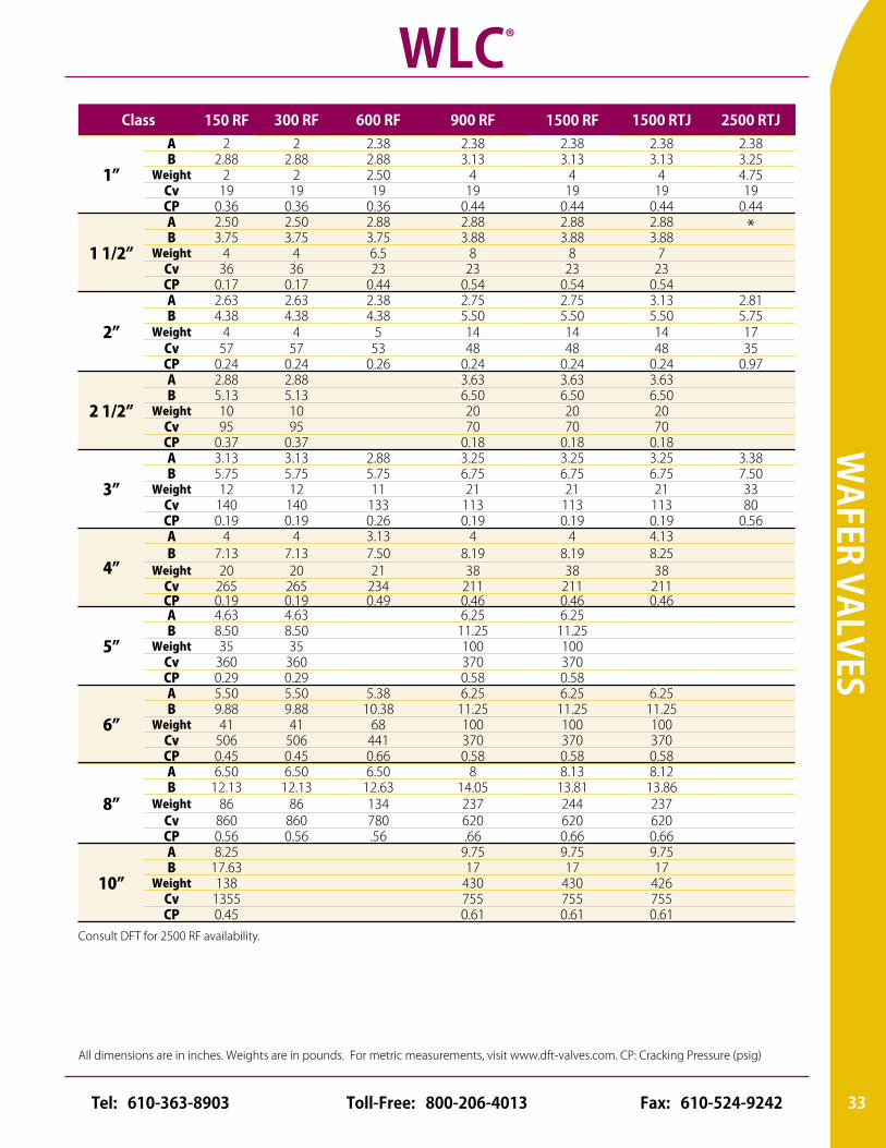
Class 150 RF 300 RF 600 RF 900 RF 1500 RF 1500 RTJ 2500 RTJ
1”
A 2 2 2.38 2.38 2.38 2.38 2.38B 2.88 2.88 2.88 3.13 3.13 3.13 3.25
Weight 2 2 2.50 4 4 4 4.75Cv 19 19 19 19 19 19 19CP 0.36 0.36 0.36 0.44 0.44 0.44 0.44
1 1/2”
A 2.50 2.50 2.88 2.88 2.88 2.88 *B 3.75 3.75 3.75 3.88 3.88 3.88
Weight 4 4 6.5 8 8 7Cv 36 36 23 23 23 23CP 0.17 0.17 0.44 0.54 0.54 0.54
2”
A 2.63 2.63 2.38 2.75 2.75 3.13 2.81B 4.38 4.38 4.38 5.50 5.50 5.50 5.75
Weight 4 4 5 14 14 14 17Cv 57 57 53 48 48 48 35CP 0.24 0.24 0.26 0.24 0.24 0.24 0.97
2 1/2”
A 2.88 2.88 3.63 3.63 3.63B 5.13 5.13 6.50 6.50 6.50
Weight 10 10 20 20 20Cv 95 95 70 70 70CP 0.37 0.37 0.18 0.18 0.18
3”
A 3.13 3.13 2.88 3.25 3.25 3.25 3.38B 5.75 5.75 5.75 6.75 6.75 6.75 7.50
Weight 12 12 11 21 21 21 33Cv 140 140 133 113 113 113 80CP 0.19 0.19 0.26 0.19 0.19 0.19 0.56
4”
A 4 4 3.13 4 4 4.13B 7.13 7.13 7.50 8.19 8.19 8.25
Weight 20 20 21 38 38 38Cv 265 265 234 211 211 211CP 0.19 0.19 0.49 0.46 0.46 0.46
5”
A 4.63 4.63 6.25 6.25B 8.50 8.50 11.25 11.25
Weight 35 35 100 100Cv 360 360 370 370CP 0.29 0.29 0.58 0.58
6”
A 5.50 5.50 5.38 6.25 6.25 6.25B 9.88 9.88 10.38 11.25 11.25 11.25
Weight 41 41 68 100 100 100Cv 506 506 441 370 370 370CP 0.45 0.45 0.66 0.58 0.58 0.58
8”
A 6.50 6.50 6.50 8 8.13 8.12B 12.13 12.13 12.63 14.05 13.81 13.86
Weight 86 86 134 237 244 237Cv 860 860 780 620 620 620CP 0.56 0.56 .56 .66 0.66 0.66
10”
A 8.25 9.75 9.75 9.75B 17.63 17 17 17
Weight 138 430 430 426Cv 1355 755 755 755CP 0.45 0.61 0.61 0.61
WLC®
Consult DFT for 2500 RF availability.
33Toll-Free: 800-206-4013 Fax: 610-524-9242Tel: 610-363-8903
Consult pages 42 and 43 for Pressure/Temperature ratings and soft seat materials.
WAF
ER V
ALVE
S
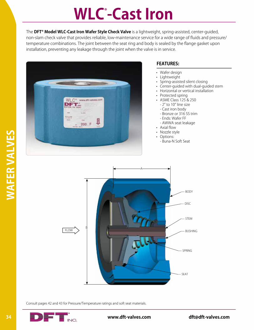
The DFT® Model WLC-Cast Iron Wafer Style Check Valve is a lightweight, spring-assisted, center-guided, non-slam check valve that provides reliable, low-maintenance service for a wide range of fluids and pressure/ temperature combinations. The joint between the seat ring and body is sealed by the flange gasket upon installation, preventing any leakage through the joint when the valve is in service.
WLC®-Cast Iron
• Wafer design• Lightweight• Spring-assisted silent closing• Center-guided with dual-guided stem• Horizontal or vertical installation• Protected spring• ASME Class 125 & 250 - 2” to 10” line size - Cast iron body - Bronze or 316 SS trim - Ends: Wafer FF - AWWA seat leakage• Axial flow• Nozzle style• Options: - Buna-N Soft Seat
FEATURES:
FLOW
— STEM
— BUSHING
— DISC
— SEAT
— BODY
— SPRING
B
A
34 www.dft-valves.com [email protected]
WAFER VALVES
All dimensions are in inches. Weights are in pounds. For metric measurements, visit www.dft-valves.com. CP: Cracking Pressure (psig)
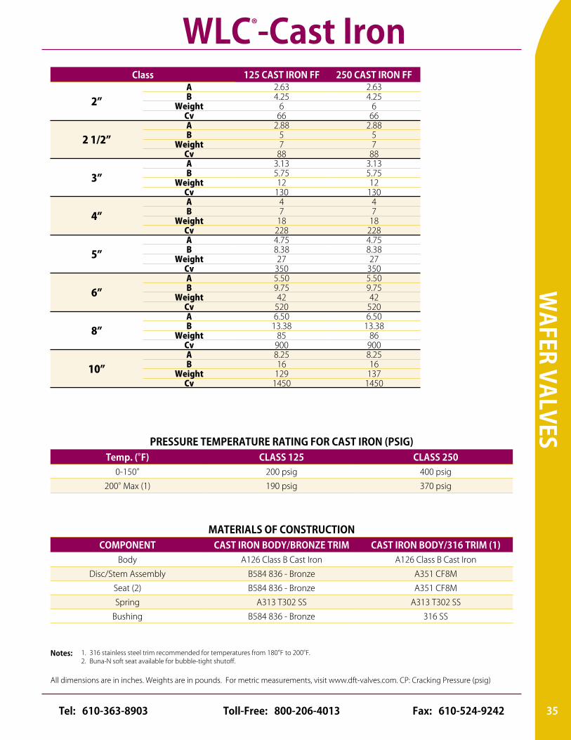
Class 125 CAST IRON FF 250 CAST IRON FF
2”A 2.63 2.63B 4.25 4.25
Weight 6 6Cv 66 66
2 1/2”A 2.88 2.88B 5 5
Weight 7 7Cv 88 88
3”A 3.13 3.13B 5.75 5.75
Weight 12 12Cv 130 130
4”A 4 4B 7 7
Weight 18 18Cv 228 228
5”A 4.75 4.75B 8.38 8.38
Weight 27 27Cv 350 350
6”A 5.50 5.50B 9.75 9.75
Weight 42 42Cv 520 520
8”A 6.50 6.50B 13.38 13.38
Weight 85 86Cv 900 900
10”A 8.25 8.25B 16 16
Weight 129 137Cv 1450 1450
PRESSURE TEMPERATURE RATING FOR CAST IRON (PSIG)Temp. (°F) CLASS 125 CLASS 250
0-150° 200 psig 400 psig
200° Max (1) 190 psig 370 psig
MATERIALS OF CONSTRUCTIONCOMPONENT CAST IRON BODY/BRONZE TRIM CAST IRON BODY/316 TRIM (1)
Body A126 Class B Cast Iron A126 Class B Cast Iron
Disc/Stem Assembly B584 836 - Bronze A351 CF8M
Seat (2) B584 836 - Bronze A351 CF8M
Spring A313 T302 SS A313 T302 SS
Bushing B584 836 - Bronze 316 SS
1. 316 stainless steel trim recommended for temperatures from 180°F to 200°F.2. Buna-N soft seat available for bubble-tight shutoff.
Notes:
WLC®-Cast Iron
35Toll-Free: 800-206-4013 Fax: 610-524-9242Tel: 610-363-8903
Consult pages 42 and 43 for Pressure/Temperature ratings and soft seat materials.
IN-L
INE
REPA
IRAB
LE V
ALVE
S
36 www.dft-valves.com [email protected]
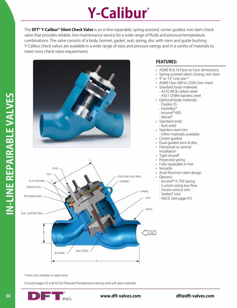
The DFT® Y-Calibur® Silent Check Valve is an in line repairable, spring-assisted, center guided, non-slam check valve that provides reliable, low-maintenance service for a wide range of fluids and pressure/temperature combinations. The valve consists of a body, bonnet, gasket, seat, spring, disc with stem and guide bushing. Y-Calibur check valves are available in a wide range of sizes and pressure ratings and in a variety of materials to meet most check valve requirements.
• ASME B16.10 Face-to-Face dimensions• Spring-assisted silent closing, non-slam• 4” to 14” Line size *• ASME Class 600 to 2500 (See chart)• Standard body materials: - A216 WCB carbon steel - A351 CF8M stainless steel• Optional body materials: - Duplex SS - Hastelloy® - Inconel® 600 - Monel®• Standard ends: - Butt weld• Stainless steel trim - Other materials available • Center-guided• Dual-guided stem & disc• Horizontal or vertical installation• Tight shutoff• Protected spring• Fully repairable in-line• Versatile• Axial flow/non-slam design• Options: - Inconel® X-750 Spring - Custom sizing low flow - Severe service trim - Stellite® trim - NACE (See page 41)
FEATURES:
Y-Calibur®
* other sizes available on application
A
FLOWB
—BODY
— BONNET
— PRESSURE SEAL RING
— SPRING
— SEAT
STUD —
NUT —
FLAT WASHER —
RETAINING RING —
SEAL SUPPORT RING —
C
DRAW PLATE —
DISC/STEM —BUSHING —
IN-LIN
E REPAIRABLE VALVES
All dimensions are in inches. Weights are in pounds. For metric measurements, visit www.dft-valves.com. CP: Cracking Pressure (psig)
37Toll-Free: 800-206-4013 Fax: 610-524-9242Tel: 610-363-8903
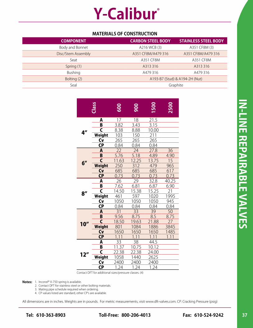
Clas
s
600
900
1500
2500
4”
A 17 18 21.5B 3.82 3.43 3.15C 8.38 8.88 10.00
Weight 103 150 211Cv 265 265 265CP 0.84 0.84 0.84
6”
A 22 24 27.8 36B 5.76 5.18 4.89 4.90C 11.63 12.25 13.75 15
Weight 250 312 479 965Cv 685 685 685 617CP 0.73 0.73 0.73 0.73
8”
A 26 29 32.8 40.25B 7.62 6.81 6.87 6.90C 14.50 15.38 15.25 21
Weight 461 597 1020 1995Cv 1050 1050 1050 945CP 0.84 0.84 0.84 0.84
10”
A 31 33 39 50B 9.56 8.75 8.5 8.75C 18.50 19.63 21.88 27
Weight 801 1084 1886 3845Cv 1650 1650 1650 1485CP 1.11 1.11 1.11 1.11
12”
A 33 38 44.5B 11.37 10.75 10.12C 22.38 22.38 24.00
Weight 1058 1440 2625Cv 2400 2400 2400CP 1.24 1.24 1.24
Contact DFT for additional sizes/pressure classes. (4)
MATERIALS OF CONSTRUCTIONCOMPONENT CARBON STEEL BODY STAINLESS STEEL BODY
Body and Bonnet A216 WCB (3) A351 CF8M (3)
Disc/Stem Assembly A351 CF8M/A479 316 A351 CF8M/A479 316
Seat A351 CF8M A351 CF8M
Spring (1) A313 316 A313 316
Bushing A479 316 A479 316
Bolting (2) A193-B7 (Stud) & A194-2H (Nut)
Seal Graphite
1. Inconel® X-750 spring is available.2. Contact DFT for stainless steel or other bolting materials.3. Mating pipe schedule required when ordering.4. CP values listed are standard, other CP’s are available.
Notes:
Y-Calibur®
Consult pages 42 and 43 for Pressure/Temperature ratings and soft seat materials.
NIC
KEL-
ALUM
INUM
BRO
NZE
VAL
VES
38 www.dft-valves.com [email protected]
GLC® - NAB
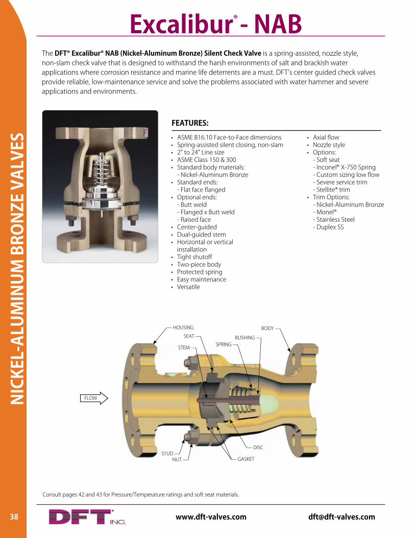
The DFT® Excalibur® NAB (Nickel-Aluminum Bronze) Silent Check Valve is a spring-assisted, nozzle style, non-slam check valve that is designed to withstand the harsh environments of salt and brackish water applications where corrosion resistance and marine life deterrents are a must. DFT’s center guided check valves provide reliable, low-maintenance service and solve the problems associated with water hammer and severe applications and environments.
Excalibur® - NAB
• Axial flow• Nozzle style• Options: - Soft seat - Inconel® X-750 Spring - Custom sizing low flow - Severe service trim - Stellite® trim • Trim Options: - Nickel-Aluminum Bronze - Monel® - Stainless Steel - Duplex SS
• ASME B16.10 Face-to-Face dimensions• Spring-assisted silent closing, non-slam• 2” to 24” Line size• ASME Class 150 & 300• Standard body materials: - Nickel-Aluminum Bronze• Standard ends: - Flat face flanged• Optional ends: - Butt weld - Flanged x Butt weld - Raised face• Center-guided• Dual-guided stem• Horizontal or vertical installation• Tight shutoff• Two-piece body• Protected spring• Easy maintenance• Versatile
FEATURES:
FLOW
— DISC
SEAT —
STUD —
— HOUSING
STEM — SPRING —BUSHING —
BODY —
NUT — — GASKET
NICKEL-ALUM
INUM
BRON
ZE VALVES
All dimensions are in inches. Weights are in pounds. For metric measurements, visit www.dft-valves.com. CP: Cracking Pressure (psig)
39Toll-Free: 800-206-4013 Fax: 610-524-9242Tel: 610-363-8903
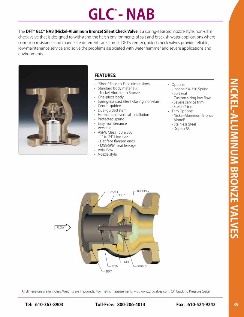
• “Short” Face-to-Face dimensions• Standard body materials: - Nickel-Aluminum Bronze• One-piece body• Spring-assisted silent closing, non-slam• Center-guided• Dual-guided stem• Horizontal or vertical installation• Protected spring• Easy maintenance• Versatile• ASME Class 150 & 300 - 1” to 24” Line size - Flat face flanged ends - MSS-SP61 seat leakage• Axial flow• Nozzle style
FEATURES:
• Options: - Inconel® X-750 Spring - Soft seat - Custom sizing low flow - Severe service trim - Stellite® trim• Trim Options: - Nickel-Aluminum Bronze - Monel® - Stainless Steel - Duplex SS
The DFT® GLC® NAB (Nickel-Aluminum Bronze) Silent Check Valve is a spring-assisted, nozzle style, non-slam check valve that is designed to withstand the harsh environments of salt and brackish water applications where corrosion resistance and marine life deterrents are a must. DFT’s center guided check valves provide reliable, low-maintenance service and solve the problems associated with water hammer and severe applications and environments.
GLC® - NAB
FLOW
— GASKET
— SPRING— DISC
— SEAT
— STEM
— BODY— BUSHING
Excalibur® - NAB
CODES & STANDARDS
ALC®
Basic
-Che
ck®
DLC
®
DSV
®
Exca
libur
®
FBC®
GLC
® &
GLC
-Cas
t Iro
n
PDC®
Rest
ricto
r Ch
eck
SCV®
SCV-
R®
Vacu
um
Brea
ker
WLC
®&
WLC
-Cas
t Iro
n
Y-Ca
libur
®
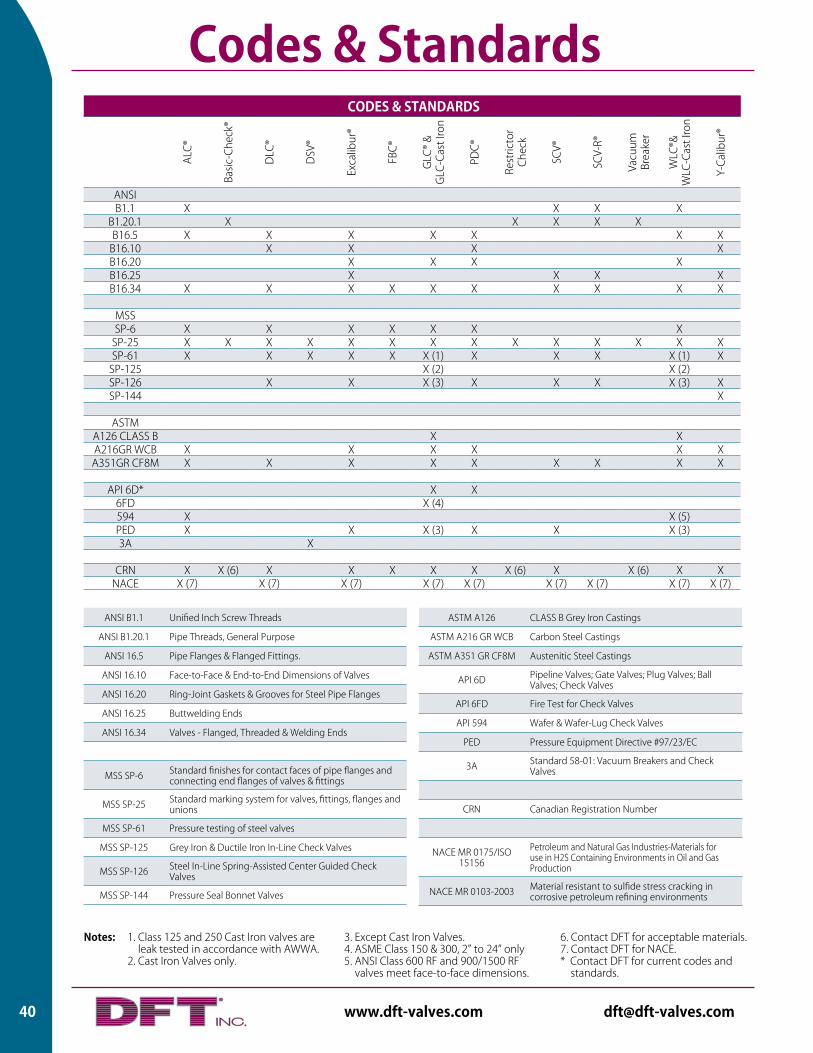
ANSIB1.1 X X X X
B1.20.1 X X X X XB16.5 X X X X X X X
B16.10 X X X XB16.20 X X X XB16.25 X X X XB16.34 X X X X X X X X X X
MSSSP-6 X X X X X X X
SP-25 X X X X X X X X X X X X X XSP-61 X X X X X X (1) X X X X (1) X
SP-125 X (2) X (2)SP-126 X X X (3) X X X X (3) XSP-144 X
ASTMA126 CLASS B X XA216GR WCB X X X X X XA351GR CF8M X X X X X X X X X
API 6D* X X6FD X (4)594 X X (5)PED X X X (3) X X X (3)3A X
CRN X X (6) X X X X X X (6) X X (6) X XNACE X (7) X (7) X (7) X (7) X (7) X (7) X (7) X (7) X (7)
Codes & Standards
1. Class 125 and 250 Cast Iron valves are leak tested in accordance with AWWA.
2. Cast Iron Valves only.
Notes: 3. Except Cast Iron Valves. 4. ASME Class 150 & 300, 2” to 24” only5. ANSI Class 600 RF and 900/1500 RF
valves meet face-to-face dimensions.
6. Contact DFT for acceptable materials. 7. Contact DFT for NACE. * Contact DFT for current codes and standards.
ANSI B1.1 Unified Inch Screw Threads
ANSI B1.20.1 Pipe Threads, General Purpose
ANSI 16.5 Pipe Flanges & Flanged Fittings.
ANSI 16.10 Face-to-Face & End-to-End Dimensions of Valves
ANSI 16.20 Ring-Joint Gaskets & Grooves for Steel Pipe Flanges
ANSI 16.25 Buttwelding Ends
ANSI 16.34 Valves - Flanged, Threaded & Welding Ends
MSS SP-6 Standard finishes for contact faces of pipe flanges and connecting end flanges of valves & fittings
MSS SP-25 Standard marking system for valves, fittings, flanges and unions
MSS SP-61 Pressure testing of steel valves
MSS SP-125 Grey Iron & Ductile Iron In-Line Check Valves
MSS SP-126 Steel In-Line Spring-Assisted Center Guided Check Valves
MSS SP-144 Pressure Seal Bonnet Valves
ASTM A126 CLASS B Grey Iron Castings
ASTM A216 GR WCB Carbon Steel Castings
ASTM A351 GR CF8M Austenitic Steel Castings
API 6D Pipeline Valves; Gate Valves; Plug Valves; Ball Valves; Check Valves
API 6FD Fire Test for Check Valves
API 594 Wafer & Wafer-Lug Check Valves
PED Pressure Equipment Directive #97/23/EC
3A Standard 58-01: Vacuum Breakers and Check Valves
CRN Canadian Registration Number
NACE MR 0175/ISO 15156
Petroleum and Natural Gas Industries-Materials for use in H2S Containing Environments in Oil and Gas Production
NACE MR 0103-2003 Material resistant to sulfide stress cracking in corrosive petroleum refining environments
40 www.dft-valves.com [email protected]
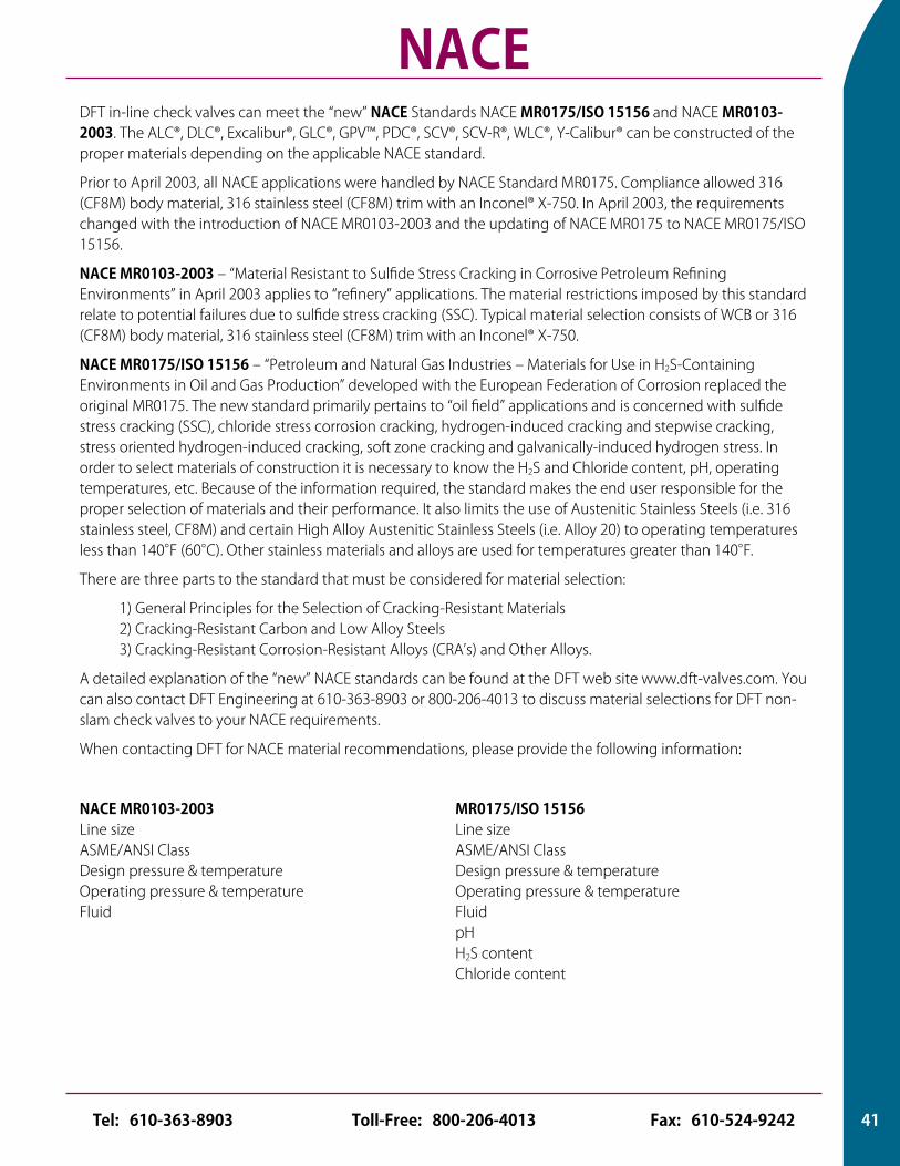
NACEDFT in-line check valves can meet the “new” NACE Standards NACE MR0175/ISO 15156 and NACE MR0103-2003. The ALC®, DLC®, Excalibur®, GLC®, GPV™, PDC®, SCV®, SCV-R®, WLC®, Y-Calibur® can be constructed of the proper materials depending on the applicable NACE standard.
Prior to April 2003, all NACE applications were handled by NACE Standard MR0175. Compliance allowed 316 (CF8M) body material, 316 stainless steel (CF8M) trim with an Inconel® X-750. In April 2003, the requirements changed with the introduction of NACE MR0103-2003 and the updating of NACE MR0175 to NACE MR0175/ISO 15156.
NACE MR0103-2003 – “Material Resistant to Sulfide Stress Cracking in Corrosive Petroleum Refining Environments” in April 2003 applies to “refinery” applications. The material restrictions imposed by this standard relate to potential failures due to sulfide stress cracking (SSC). Typical material selection consists of WCB or 316 (CF8M) body material, 316 stainless steel (CF8M) trim with an Inconel® X-750.
NACE MR0175/ISO 15156 – “Petroleum and Natural Gas Industries – Materials for Use in H2S-Containing Environments in Oil and Gas Production” developed with the European Federation of Corrosion replaced the original MR0175. The new standard primarily pertains to “oil field” applications and is concerned with sulfide stress cracking (SSC), chloride stress corrosion cracking, hydrogen-induced cracking and stepwise cracking, stress oriented hydrogen-induced cracking, soft zone cracking and galvanically-induced hydrogen stress. In order to select materials of construction it is necessary to know the H2S and Chloride content, pH, operating temperatures, etc. Because of the information required, the standard makes the end user responsible for the proper selection of materials and their performance. It also limits the use of Austenitic Stainless Steels (i.e. 316 stainless steel, CF8M) and certain High Alloy Austenitic Stainless Steels (i.e. Alloy 20) to operating temperatures less than 140°F (60°C). Other stainless materials and alloys are used for temperatures greater than 140°F.
There are three parts to the standard that must be considered for material selection:
1) General Principles for the Selection of Cracking-Resistant Materials 2) Cracking-Resistant Carbon and Low Alloy Steels 3) Cracking-Resistant Corrosion-Resistant Alloys (CRA’s) and Other Alloys.
A detailed explanation of the “new” NACE standards can be found at the DFT web site www.dft-valves.com. You can also contact DFT Engineering at 610-363-8903 or 800-206-4013 to discuss material selections for DFT non-slam check valves to your NACE requirements.
When contacting DFT for NACE material recommendations, please provide the following information:
NACE MR0103-2003 Line size ASME/ANSI Class Design pressure & temperature Operating pressure & temperature Fluid
MR0175/ISO 15156 Line size ASME/ANSI Class Design pressure & temperature Operating pressure & temperature Fluid pH H2S content Chloride content
41Toll-Free: 800-206-4013 Fax: 610-524-9242Tel: 610-363-8903
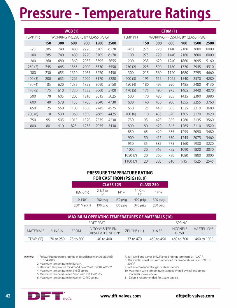
WCB (1)TEMP. (°F) WORKING PRESSURE BY CLASS (PSIG)
150 300 600 900 1500 2500-20 285 740 1480 2220 3705 6170
100 285 740 1480 2220 3705 6170
200 260 680 1360 2035 3395 5655
250 (2) 245 665 1335 2000 3330 5550
300 230 655 1310 1965 3270 5450
400 (3) 200 635 1265 1900 3170 5280
450 (4) 185 620 1235 1855 3090 5150
470 (5) 175 610 1220 1835 3060 5100
500 170 605 1205 1810 3015 5025
600 140 570 1135 1705 2840 4730
650 125 550 1100 1650 2745 4575
700 (6) 110 530 1060 1590 2665 4425
750 95 505 1015 1520 2535 4230
800 80 410 825 1235 2055 3430
CF8M (1)TEMP. (°F) WORKING PRESSURE BY CLASS (PSIG)
150 300 600 900 1500 2500-462 275 720 1440 2160 3600 6000
100 275 720 1440 2160 3600 6000
200 235 620 1240 1860 3095 5160
250 (2) 225 590 1180 1770 2945 4910
300 215 560 1120 1680 2795 4660
400 (3) 195 515 1025 1540 2570 4280
450 (4) 180 495 990 1485 2480 4130
470 (5) 175 490 975 1465 2440 4070
500 170 480 955 1435 2390 3980
600 140 450 900 1355 2255 3760
650 125 440 885 1325 2210 3680
700 (6) 110 435 870 1305 2170 3620
750 95 425 855 1280 2135 3560
800 80 420 845 1265 2110 3520
850 65 420 835 1255 2090 3480
900 50 415 830 1245 2075 3460
950 35 385 775 1160 1930 3220
1000 20 365 725 1090 1820 3030
1050 (7) 20 360 720 1080 1800 3000
1100 (7) 20 305 610 915 1525 2545
1. Pressure/temperature ratings in accordance with ASME/ANSI B16.34-2013.
2. Maximum temperature for Buna-N. 3. Maximum temperature for Viton® & Zelon® with 3600 CWP SCV. 4. Maximum temperature for 316 SS spring. 5. Maximum temperature for Zelon with 750 CWP SCV. 6. Maximum temperature for Inconel® X-750 spring.
Notes: 7. Butt weld end valves only. Flanged ratings terminate at 1000° F. 8. 316 stainless steel trim recommended for temperatures from 180°F to
200° F. 9. Not recommended for gas or steam service 10. Maximum valve temperature rating is limited by seal and spring
materials shown above. 11. Zelon is recommended for steam service.
PRESSURE TEMPERATURE RATING FOR CAST IRON (PSIG) (8, 9)
CLASS 125 CLASS 250
TEMP. (°F) 2 1/2 to 12” 14” + 2 1/2 to
12” 14” +
0-150° 200 psig 150 psig 400 psig 300 psig
200° Max (1) 190 psig 135 psig 370 psig 280 psig
MAXIMUM OPERATING TEMPERATURES OF MATERIALS (10)SOFT SEAT SPRING
MATERIALS BUNA-N EPDM VITON® & TFE-EN-CAPSULATED VITON® ZELON® (11) 316 SS INCONEL®
X-750HASTELLOY®
C
TEMP. (°F) -70 to 250 -75 to 300 -40 to 400 37 to 470 -460 to 450 -460 to 700 -460 to 1000
Pressure - Temperature Ratings
42 www.dft-valves.com [email protected]
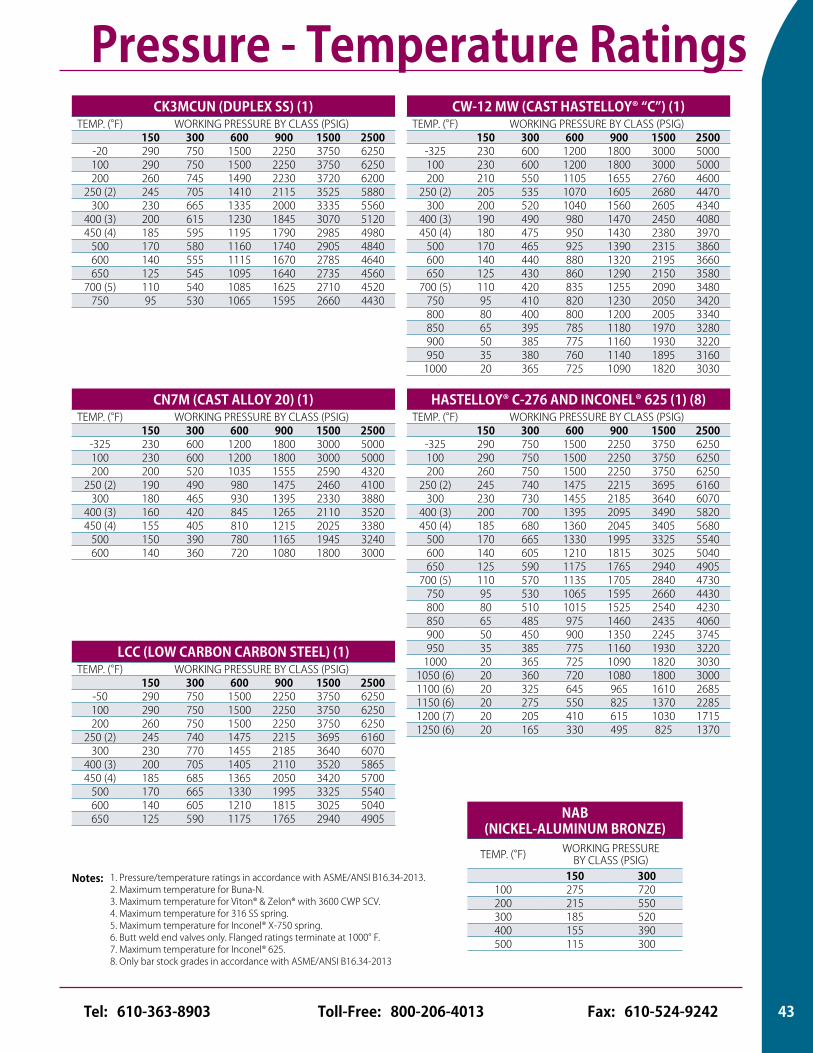
CK3MCUN (DUPLEX SS) (1)TEMP. (°F) WORKING PRESSURE BY CLASS (PSIG)
150 300 600 900 1500 2500-20 290 750 1500 2250 3750 6250100 290 750 1500 2250 3750 6250200 260 745 1490 2230 3720 6200
250 (2) 245 705 1410 2115 3525 5880300 230 665 1335 2000 3335 5560
400 (3) 200 615 1230 1845 3070 5120450 (4) 185 595 1195 1790 2985 4980
500 170 580 1160 1740 2905 4840600 140 555 1115 1670 2785 4640650 125 545 1095 1640 2735 4560
700 (5) 110 540 1085 1625 2710 4520750 95 530 1065 1595 2660 4430
CN7M (CAST ALLOY 20) (1)TEMP. (°F) WORKING PRESSURE BY CLASS (PSIG)
150 300 600 900 1500 2500-325 230 600 1200 1800 3000 5000100 230 600 1200 1800 3000 5000200 200 520 1035 1555 2590 4320
250 (2) 190 490 980 1475 2460 4100300 180 465 930 1395 2330 3880
400 (3) 160 420 845 1265 2110 3520450 (4) 155 405 810 1215 2025 3380
500 150 390 780 1165 1945 3240600 140 360 720 1080 1800 3000
CW-12 MW (CAST HASTELLOY® “C”) (1)TEMP. (°F) WORKING PRESSURE BY CLASS (PSIG)
150 300 600 900 1500 2500-325 230 600 1200 1800 3000 5000100 230 600 1200 1800 3000 5000200 210 550 1105 1655 2760 4600
250 (2) 205 535 1070 1605 2680 4470300 200 520 1040 1560 2605 4340
400 (3) 190 490 980 1470 2450 4080450 (4) 180 475 950 1430 2380 3970
500 170 465 925 1390 2315 3860600 140 440 880 1320 2195 3660650 125 430 860 1290 2150 3580
700 (5) 110 420 835 1255 2090 3480750 95 410 820 1230 2050 3420800 80 400 800 1200 2005 3340850 65 395 785 1180 1970 3280900 50 385 775 1160 1930 3220950 35 380 760 1140 1895 3160
1000 20 365 725 1090 1820 3030
LCC (LOW CARBON CARBON STEEL) (1)TEMP. (°F) WORKING PRESSURE BY CLASS (PSIG)
150 300 600 900 1500 2500-50 290 750 1500 2250 3750 6250100 290 750 1500 2250 3750 6250200 260 750 1500 2250 3750 6250
250 (2) 245 740 1475 2215 3695 6160300 230 770 1455 2185 3640 6070
400 (3) 200 705 1405 2110 3520 5865450 (4) 185 685 1365 2050 3420 5700
500 170 665 1330 1995 3325 5540600 140 605 1210 1815 3025 5040650 125 590 1175 1765 2940 4905
HASTELLOY® C-276 AND INCONEL® 625 (1) (8)TEMP. (°F) WORKING PRESSURE BY CLASS (PSIG)
150 300 600 900 1500 2500-325 290 750 1500 2250 3750 6250100 290 750 1500 2250 3750 6250200 260 750 1500 2250 3750 6250
250 (2) 245 740 1475 2215 3695 6160300 230 730 1455 2185 3640 6070
400 (3) 200 700 1395 2095 3490 5820450 (4) 185 680 1360 2045 3405 5680
500 170 665 1330 1995 3325 5540600 140 605 1210 1815 3025 5040650 125 590 1175 1765 2940 4905
700 (5) 110 570 1135 1705 2840 4730750 95 530 1065 1595 2660 4430800 80 510 1015 1525 2540 4230850 65 485 975 1460 2435 4060900 50 450 900 1350 2245 3745950 35 385 775 1160 1930 3220
1000 20 365 725 1090 1820 30301050 (6) 20 360 720 1080 1800 30001100 (6) 20 325 645 965 1610 26851150 (6) 20 275 550 825 1370 22851200 (7) 20 205 410 615 1030 17151250 (6) 20 165 330 495 825 1370
1. Pressure/temperature ratings in accordance with ASME/ANSI B16.34-2013. 2. Maximum temperature for Buna-N. 3. Maximum temperature for Viton® & Zelon® with 3600 CWP SCV. 4. Maximum temperature for 316 SS spring. 5. Maximum temperature for Inconel® X-750 spring.6. Butt weld end valves only. Flanged ratings terminate at 1000° F. 7. Maximum temperature for Inconel® 625.8. Only bar stock grades in accordance with ASME/ANSI B16.34-2013
Notes:
Pressure - Temperature Ratings
NAB (NICKEL-ALUMINUM BRONZE)
TEMP. (°F) WORKING PRESSURE BY CLASS (PSIG)
150 300100 275 720200 215 550300 185 520400 155 390500 115 300
43Toll-Free: 800-206-4013 Fax: 610-524-9242Tel: 610-363-8903
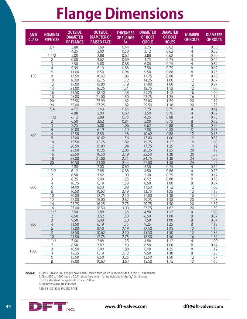
ANSI CLASS
NOMINAL PIPE SIZE
OUTSIDE DIAMETER OF FLANGE
OUTSIDE DIAMETER OF RAISED FACE
THICKNESS OF FLANGE
tf
DIAMETER OF BOLT CIRCLE
DIAMETER OF BOLT HOLES
NUMBER OF BOLTS
DIAMETER OF BOLTS
150
3/4 3.88 1.69 0.44 2.75 0.62 4 0.501 4.25 2.00 0.50 3.12 0.62 4 0.50
1 1/2 5.00 2.88 0.62 3.88 0.62 4 0.502 6.00 3.62 0.69 4.75 0.75 4 0.623 7.50 5.00 0.88 6.00 0.75 4 0.624 9.99 6.19 0.88 7.50 0.75 8 0.626 11.00 8.50 0.94 9.50 0.88 8 0.758 13.50 10.62 1.06 11.75 0.88 8 0.75
10 16.00 12.75 1.12 14.25 1.00 12 0.8712 19.00 15.00 1.19 17.00 1.00 12 0.8714 21.00 16.25 1.31 18.75 1.12 12 1.0016 23.50 18.50 1.38 21.25 1.12 16 1.0018 25.00 21.00 1.50 22.75 1.25 16 1.1220 27.50 23.99 1.62 25.00 1.25 20 1.1224 32.00 27.25 1.82 29.50 1.38 20 1.25
300
3/4 4.62 1.69 0.56 3.25 0.75 4 0.621 4.88 2.00 0.62 3.50 0.75 4 0.62
1 1/2 6.12 2.88 0.75 4.25 0.88 4 0.752 6.50 3.62 0.81 5.00 0.75 8 0.623 8.25 5.00 1.06 6.62 0.88 8 0.754 10.00 6.19 1.19 7.88 0.88 8 0.756 12.50 8.50 1.38 10.62 0.88 12 0.758 15.00 10.62 1.56 13.00 1.00 12 0.87
10 17.50 12.75 1.82 15.25 1.12 16 1.0012 20.50 15.00 1.94 17.75 1.25 16 1.1214 23.00 16.25 2.06 20.25 1.25 20 1.1216 25.50 18.50 2.19 22.50 1.38 20 1.2518 28.00 21.00 2.31 24.75 1.38 24 1.2520 30.50 23.00 2.44 27.00 1.38 24 1.25
600
1 4.88 2.00 0.69 3.50 0.75 4 0.621 1/2 6.12 2.88 0.88 4.50 0.88 4 0.75
2 6.50 3.62 1.00 5.00 0.75 8 0.623 8.25 5.00 1.25 6.62 0.88 8 0.754 10.75 6.19 1.50 8.50 1.00 8 0.876 14.00 8.50 1.88 11.50 1.12 12 1.008 16.50 10.62 2.19 13.75 1.25 12 1.12
10 20.00 12.75 2.50 17.00 1.38 16 1.2512 22.00 15.00 2.62 19.25 1.38 20 1.2514 23.75 16.25 2.75 20.75 1.50 20 1.3716 27.00 18.50 3.00 23.75 1.62 20 1.50
900
1 1/2 7.00 2.88 1.25 4.88 1.12 4 1.002 8.50 3.62 1.50 6.50 1.00 8 0.873 9.50 5.00 1.50 7.50 1.00 8 0.874 11.50 6.19 1.75 9.25 1.25 8 1.126 15.00 8.50 2.19 12.50 1.25 12 1.128 18.50 10.62 2.50 15.50 1.50 12 1.37
10 21.50 12.75 2.75 18.50 1.50 16 1.37
1500
1 1/2 7.00 2.88 1.25 4.88 1.12 4 1.002 8.50 3.62 1.50 6.50 1.00 8 0.873 10.50 5.00 1.88 8.00 1.25 8 1.124 12.25 6.19 2.12 9.50 1.38 8 1.256 15.50 8.50 3.25 12.50 1.50 12 1.378 19.00 10.62 3.62 15.50 1.75 12 1.62
1. Class 150 and 300 flanges have a 0.06” raised face which is not included in the “tf” dimension.2. Class 600 to 1500 have a 0.25” raised face which is not included in the “tf” dimension.3. DFT’s standard flange finish is 125 - 250 Ra.4. All dimensions are in inches
ASME B16.5-2013 RAISED FACE
Notes:
Flange Dimensions
44 www.dft-valves.com [email protected]
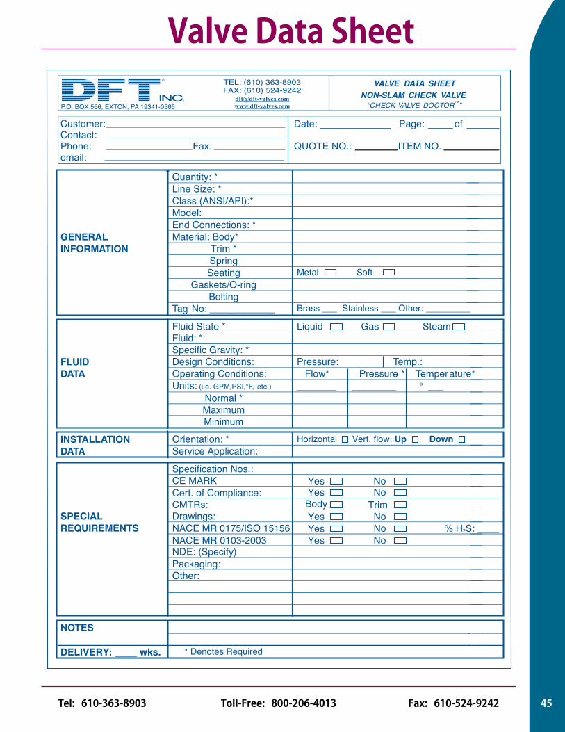
Valve Data SheetVALVE DATA SHEET
NON-SLAM CHECK VALVE“CHECK VALVE DOCTOR™”
Customer: Date: Page: of Contact: Phone: Fax: QUOTE NO.: ITEM NO. email:
Quantity: *Line Size: *Class (ANSI/API):*Model:End Connections: *
GENERAL Material: Body*INFORMATION Trim *
SpringSeating Metal Soft
Gaskets/O-ringBolting
Tag No: ____________ Brass ___ Stainless ___ Other: _________
Fluid State * Liquid Gas SteamFluid: *Specific Gravity: *
FLUID Design Conditions: Pressure: Temp.:DATA Operating Conditions: Flow* Pressure * Temperature*
Units: (i.e. GPM,PSI,°F, etc.) ________ _________ ° ___Normal *MaximumMinimum
INSTALLATION Orientation: * Horizontal Vert. flow: Up DownDATA Service Application:
Specification Nos.:
Cert. CE MARK
of Compliance:
CMTRs:
SPECIALNACE MR 0175/ISO 15156NACE MR 0103-2003
REQUIREMENTS
NDE: (Specify)
Packaging:Other:
NOTES
DELIVERY: ____ wks. * Denotes Required
Body Trim
Yes No % H2S: ____
Yes No Yes No
Yes No
Drawings: Yes No
P.O. BOX 566, EXTON, PA 19341-0566
TEL: (610) 363-8903FAX: (610) 524-9242
39
45Toll-Free: 800-206-4013 Fax: 610-524-9242Tel: 610-363-8903
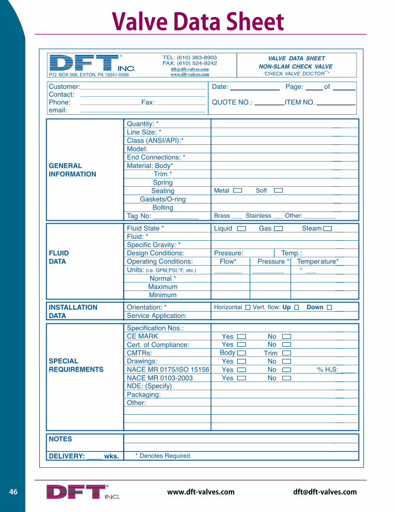
Warranty
VALVE DATA SHEETNON-SLAM CHECK VALVE
“CHECK VALVE DOCTOR™”
Customer: Date: Page: of Contact: Phone: Fax: QUOTE NO.: ITEM NO. email:
Quantity: *Line Size: *Class (ANSI/API):*Model:End Connections: *
GENERAL Material: Body*INFORMATION Trim *
SpringSeating Metal Soft
Gaskets/O-ringBolting
Tag No: ____________ Brass ___ Stainless ___ Other: _________
Fluid State * Liquid Gas SteamFluid: *Specific Gravity: *
FLUID Design Conditions: Pressure: Temp.:DATA Operating Conditions: Flow* Pressure * Temperature*
Units: (i.e. GPM,PSI,°F, etc.) ________ _________ ° ___Normal *MaximumMinimum
INSTALLATION Orientation: * Horizontal Vert. flow: Up DownDATA Service Application:
Specification Nos.:
Cert. CE MARK
of Compliance:
CMTRs:
SPECIALNACE MR 0175/ISO 15156NACE MR 0103-2003
REQUIREMENTS
NDE: (Specify)
Packaging:Other:
NOTES
DELIVERY: ____ wks. * Denotes Required
Body Trim
Yes No % H2S: ____
Yes No Yes No
Yes No
Drawings: Yes No
P.O. BOX 566, EXTON, PA 19341-0566
TEL: (610) 363-8903FAX: (610) 524-9242
39
Valve Data Sheet
46 www.dft-valves.com [email protected]
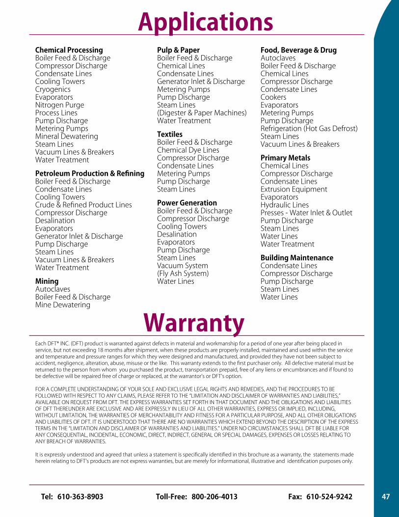
Applications
Each DFT® INC. (DFT) product is warranted against defects in material and workmanship for a period of one year after being placed in service, but not exceeding 18 months after shipment, when these products are properly installed, maintained and used within the service and temperature and pressure ranges for which they were designed and manufactured, and provided they have not been subject to accident, negligence, alteration, abuse, misuse or the like. This warranty extends to the first purchaser only. All defective material must be returned to the person from whom you purchased the product, transportation prepaid, free of any liens or encumbrances and if found to be defective will be repaired free of charge or replaced, at the warrantor’s or DFT’s option.
FOR A COMPLETE UNDERSTANDING OF YOUR SOLE AND EXCLUSIVE LEGAL RIGHTS AND REMEDIES, AND THE PROCEDURES TO BE FOLLOWED WITH RESPECT TO ANY CLAIMS, PLEASE REFER TO THE “LIMITATION AND DISCLAIMER OF WARRANTIES AND LIABILITIES,” AVAILABLE ON REQUEST FROM DFT. THE EXPRESS WARRANTIES SET FORTH IN THAT DOCUMENT AND THE OBLIGATIONS AND LIABILITIES OF DFT THEREUNDER ARE EXCLUSIVE AND ARE EXPRESSLY IN LIEU OF ALL OTHER WARRANTIES, EXPRESS OR IMPLIED, INCLUDING, WITHOUT LIMITATION, THE WARRANTIES OF MERCHANTABILITY AND FITNESS FOR A PARTICULAR PURPOSE, AND ALL OTHER OBLIGATIONS AND LIABILITIES OF DFT. IT IS UNDERSTOOD THAT THERE ARE NO WARRANTIES WHICH EXTEND BEYOND THE DESCRIPTION OF THE EXPRESS TERMS IN THE “LIMITATION AND DISCLAIMER OF WARRANTIES AND LIABILITIES.” UNDER NO CIRCUMSTANCES SHALL DFT BE LIABLE FOR ANY CONSEQUENTIAL, INCIDENTAL, ECONOMIC, DIRECT, INDIRECT, GENERAL OR SPECIAL DAMAGES, EXPENSES OR LOSSES RELATING TO ANY BREACH OF WARRANTIES.
It is expressly understood and agreed that unless a statement is specifically identified in this brochure as a warranty, the statements made herein relating to DFT’s products are not express warranties, but are merely for informational, illustrative and identification purposes only.
Chemical ProcessingBoiler Feed & Discharge Compressor Discharge Condensate LinesCooling Towers Cryogenics Evaporators Nitrogen PurgeProcess LinesPump DischargeMetering Pumps Mineral DewateringSteam LinesVacuum Lines & BreakersWater Treatment
Petroleum Production & RefiningBoiler Feed & DischargeCondensate LinesCooling TowersCrude & Refined Product Lines Compressor DischargeDesalinationEvaporatorsGenerator Inlet & DischargePump DischargeSteam LinesVacuum Lines & BreakersWater Treatment
MiningAutoclaves Boiler Feed & Discharge Mine Dewatering
Pulp & PaperBoiler Feed & DischargeChemical Lines Condensate LinesGenerator Inlet & Discharge Metering Pumps Pump Discharge Steam Lines(Digester & Paper Machines)Water Treatment
TextilesBoiler Feed & DischargeChemical Dye Lines Compressor DischargeCondensate Lines Metering PumpsPump Discharge Steam Lines
Power GenerationBoiler Feed & Discharge Compressor DischargeCooling TowersDesalinationEvaporatorsPump DischargeSteam LinesVacuum System(Fly Ash System)Water Lines
Food, Beverage & DrugAutoclaves Boiler Feed & DischargeChemical Lines Compressor Discharge Condensate Lines CookersEvaporatorsMetering Pumps Pump Discharge Refrigeration (Hot Gas Defrost)Steam LinesVacuum Lines & Breakers
Primary MetalsChemical Lines Compressor Discharge Condensate LinesExtrusion Equipment EvaporatorsHydraulic LinesPresses - Water Inlet & Outlet Pump DischargeSteam LinesWater LinesWater Treatment
Building MaintenanceCondensate LinesCompressor DischargePump DischargeSteam LinesWater Lines
Warranty
Valve Data Sheet
47Toll-Free: 800-206-4013 Fax: 610-524-9242Tel: 610-363-8903
DFT® INC.140 Sheree Blvd., P.O. Box 566, Exton, PA 19341-0566
610-363-8903800-206-4013
FAX 610-524-9242e-mail: [email protected]
internet: www.dft-valves.com
REPRESENTED BY
Printed in U.S.A. Copyright 2008, DFT® Inc., All Rights Reserved 06/08 Rev. #9Printed in U.S.A. Copyright 2016, DFT Inc., All Rights Reserved REV 3 11/16
REPRESENTED BY
DFT® INC.140 Sheree Blvd., P.O. Box 566, Exton, PA 19341-0566
610-363-8903800-206-4013
FAX 610-524-9242e-mail: [email protected]
internet: www.dft-valves.com
®
®
®6D-0885