1
Solar Sail Propulsion
Les Johnson
NASA Marshall Space Flight Center
https://ntrs.nasa.gov/search.jsp?R=20120016691 2018-05-12T12:46:16+00:00Z

2
Sail Module
u
u
1
23
4
5u
u
u
LAUNCH: 3-19-12
C3 = 0.25 km2/S
2
START SAIL PHASE: 3-29-12
START CRANKING PHASE: 7-8-14
END CRANKING PHASE: 3-8-17
START SCIENCE OPERATIONS: 3-8-17
Solar Sails Solar sails use photon “pressure” or
force on thin, lightweight reflective
sheet to produce thrust. Sails can
open up new regions of the solar
system to accessibility for important
science missions, with no propellants
required.
Observatory
150 m
Y

3
Solar SailsPropulsion from Photon Momentum Exchange
Direction
of orbit
Solar sail
Force
component
away from
sun
Incident
SunlightSun
Shrinking
orbit
Force component
back along orbit
Net Force
Component from
solar pressure
Reflecting thephotons forwardalong the directionof motion slows thespacecraft down.
An example of how a solar sail propulsion can change orbits

Solar Sail Control Angles
Thrust vector is dependent on two angles
• Cone Angle (α) (a.k.a. Sun Incidence Angle)
• Clock Angle (δ)
Direction NormalOrbit - ˆ
Direction TangentialOrbit - ˆ
Direction Radial - ˆ
N
T
R
5
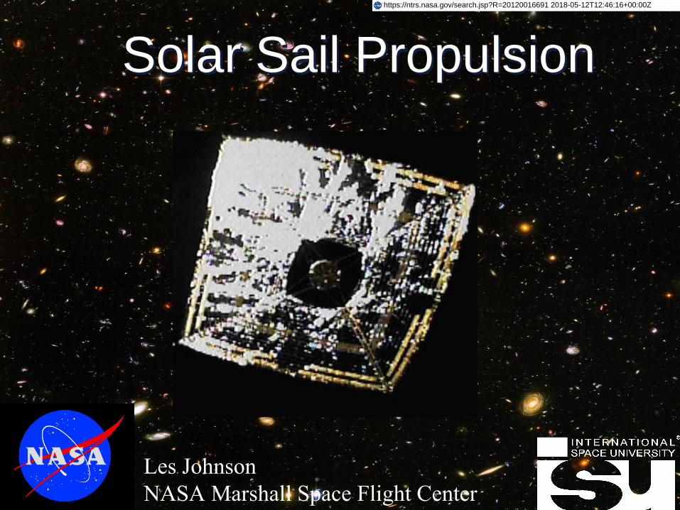
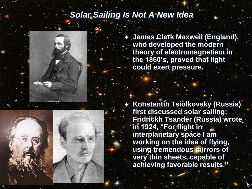
Solar Sailing Is Not A New Idea
James Clerk Maxwell (England), who developed the modern theory of electromagnetism in the 1860’s, proved that light could exert pressure.
Konstantin Tsiolkovsky (Russia) first discussed solar sailing; Fridrickh Tsander (Russia) wrote in 1924, “For flight in interplanetary space I am working on the idea of flying, using tremendous mirrors of very thin sheets, capable of achieving favorable results.”

6
Echo II 1964solar thrust affect on spacecraft orbit
• 135-foot rigidized inflatable balloon satellite
• laminated Mylar plastic and aluminum
• placed in near-polar Orbit
• passive communications experiment by NASA on January 25, 1964.
Spherical shape has no
solar pressure torques –
enabling direct
observation of thrust
effects without regard to
spacecraft attitude
When folded satellite is packed into the 41-inch
diameter canister shown in the foreground

7
Used Since 1962
Solar Sail Technology History
Solar Sailing was initially developed at JPL as a
measure to save the Mariner 10 mission which
had lost a large portion of its propellant margin
when the star tracker locked on to floating debris
instead of Canopus. The mission went on to flyby
Venus and three encounters with Mercury. Its
successful implementation on that mission led to
it being declared a mature technology, ready for
application to future NASA missions in 1978.
Several Comsats (e.g. INSAT 2E) operating today in GEO use solar pressure to unload momentum wheels or offset solar torques on asymmetric solar arrays.
Chosen for Halley Comet Rendezvous in 1985, it was replaced by a chemical rocket in phase B due to launch date/window pressure
Joint NASA/NOAA/USAF proposal to NMP ST5 fell in the 11th hour when USAF/NASA/NOAA partnership collapsed
Planetary society launched a flight experiment and a full system on converted Russian Volna sub-launched missiles. Unfortunately both boosters had stage separation failures.
2010: JAXA launches the world’s first true solar sail on a journey past Venus.
2011: NASA launches a subscale “drag sail” into Low Earth Orbit.
[Stowed Sail] (1991
Mariner 2 Dacron
Solar Sail (1962)solar sails on Mariner IV (1964)
Mariner 10: ”the solar sailing technique for conservation of attitude
control gas was improvised successfully and thereby qualified as a
technique for use in future missions.” – Bruce Murray, Flight to
Mercury, Columbia University Press 1977, page 142.

8
Geostorm: Solar Storm Warning

Use a solar sail to achieve a non-Keplerian orbit near the sun-earth line, twice as far from the
earth as the current warning system, NOAA’s Advanced Composition Explorer (ACE) at the L1
point
Geostorm will double the warning time to enable the reconfiguration and securing of space systems
(and ground electrical power grids) to avoid:
• Complete or partial loss of HF & satellite communications
• Degraded navigational and geo-locational capability
• False returns on ATC and early warning radars
• Satellite system disruption and lock problems
Geostorm, being propellantless, could result in a significantly longer spacecraft lifetime
The Geostorm MissionWarning Earth of Impending Coronal Mass Ejections
Sun
Earth
Geostorm with 70 m sail
Solar radio disk
+
Halo orbit
ACE
0.002 au
1 L
Coronal Mass Ejection (CME)
0.02 AU
0.01 AU
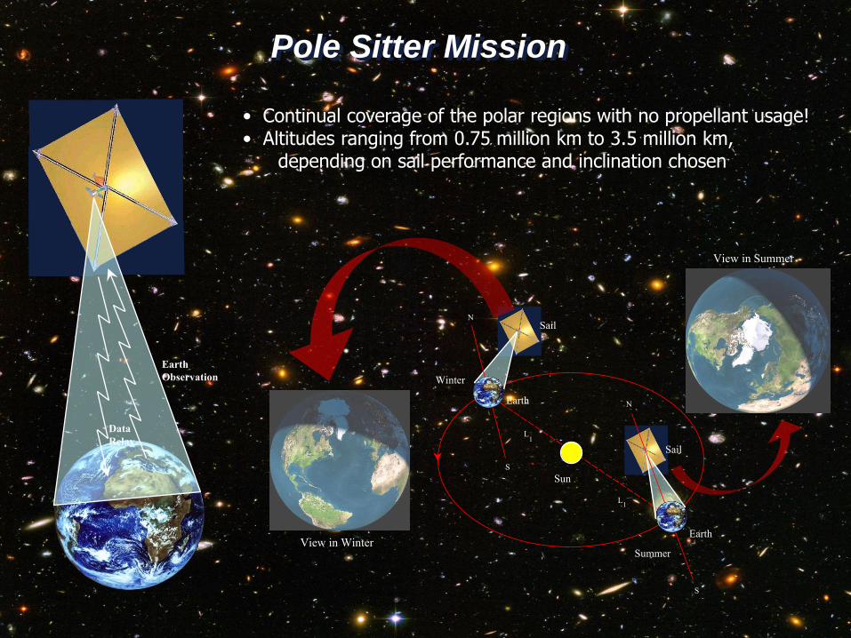
Pole Sitter Mission
Data
Relay
Earth
Observation
Sun
N
S
N
S
Summer
solstice
Winter
solstice
L1
L1
Sail
Earth
Earth
Sail
View in Winter
View in Summer
• Continual coverage of the polar regions with no propellant usage!• Altitudes ranging from 0.75 million km to 3.5 million km,
depending on sail performance and inclination chosen

Pole Sitter Spacecraft
11
Constantly above an Earth
pole
Continuous hemispheric view
of the pole
New vantage point for
telecommunications satellites
and Earth observing satellites

Solar Sail Asteroid Rendezvous Mission (rendezvous with 3 NEO’s in 6 years):
Departure: Aug 2017
Candidate asteroids visited:
NEO Date Observation Period
1999 A010 Mar 2019 35 days
Apophis Dec 2021 30 days
2001 QJ142 July 2023 30 days
• Ground Rules:
• Use existing spacecraft and components
• Use existing instruments
• Use NASA-developed sail technology
• Solar Sail Spacecraft Launch Mass: 328.6 kg
• Mass at destination: 228.4 kg
• Cost: $175M, plus launch vehicle and ops

Missions From Earth
2.12
2.42
2.68
3.25
1.55
2.10
2.382.49
2.86
1.00
1.50
2.00
2.50
3.00
3.50
0 0.05 0.1 0.15 0.2 0.25 0.3
Mis
sio
n E
lap
sed
Tim
e
(Ye
ars
)
Characteristic Acceleration mm/s2
2000 SG344
1999 AO10
Apophis
2009 CV
Note: Launch window constrained between January 1, 2017 to
January 1, 2020

14
Solar Sail Comet Chaser
• Use the unique capabilities of a
solar sail to study the life cycle of a
comet within the inner solar
system
• Place science spacecraft in
a propulsive co-orbit with a
comet
• Acquire the comet between
the orbits of Mars and Jupiter
• Follow the comet through
perihelion and as far out as
possible
15
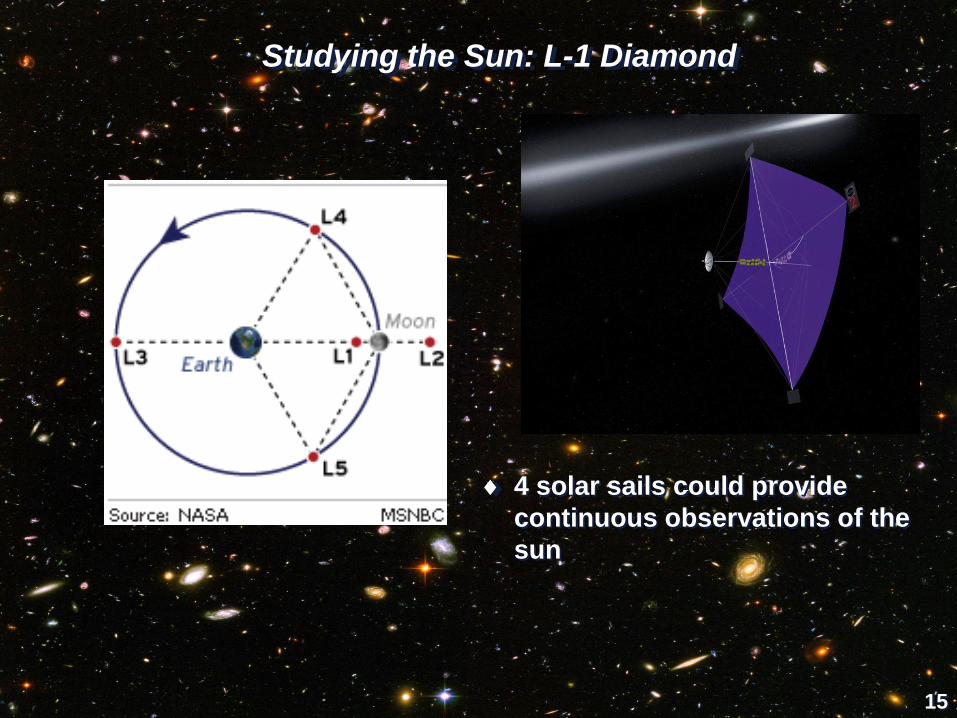
Studying the Sun: L-1 Diamond
4 solar sails could provide
continuous observations of the
sun

16
Solar Far-Side Sentinel
• Far side observations hold promise as an
indicator of upcoming earth side activity
• With opposition orbit the sun blocks
earth communication
• Options include two satellites in ecliptic
or 1 solar sail orbiting above the sun
• Solar sail enables high degree of
flexibility in orbits and mission ops
• Farside Sentinel is 1 of a 6 spacecraft
mission to study 1) the acceleration and
transport of SEPs and 2) the initiation and
evolution of CMEs and interplanetary
shocks in the inner heliosphere.
• Will provide a major advancement toward
the future ability to forecast space weather
events.

17
Solar Sail Cargo Ships
Fleets of propellantless solar sails could be the cargo ships of the future
(Operating within the inner solar system – near the sun)
18
Solar Sails Enable Interstellar Travel

19
Our Solar Neighborhood
20
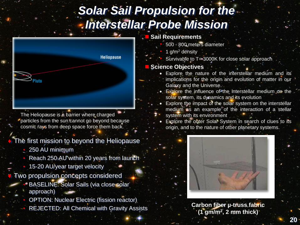
The first mission to beyond the Heliopause
• 250 AU minimum
• Reach 250 AU within 20 years from launch
• 15-20 AU/year target velocity
Two propulsion concepts considered
• BASELINE: Solar Sails (via close solar
approach)
• OPTION: Nuclear Electric (fission reactor)
• REJECTED: All Chemical with Gravity Assists
The Heliopause is a barrier where charged
particles from the sun cannot go beyond because
cosmic rays from deep space force them back.
Carbon fiber µ-truss fabric
(1 gm/m2, 2 mm thick)
Sail Requirements
• 500 - 800 meters diameter
• 1 g/m2 density
• Survivable to T= 3000K for close solar approach
Science Objectives Explore the nature of the interstellar medium and its
implications for the origin and evolution of matter in our
Galaxy and the Universe.
Explore the influence of the interstellar medium on the
solar system, its dynamics and its evolution
Explore the impact of the solar system on the interstellar
medium as an example of the interaction of a stellar
system with its environment
Explore the outer Solar System in search of clues to its
origin, and to the nature of other planetary systems.
Solar Sail Propulsion for the
Interstellar Probe Mission

21
Interstellar Probe Flight ConfigurationFully Deployed Sail
22
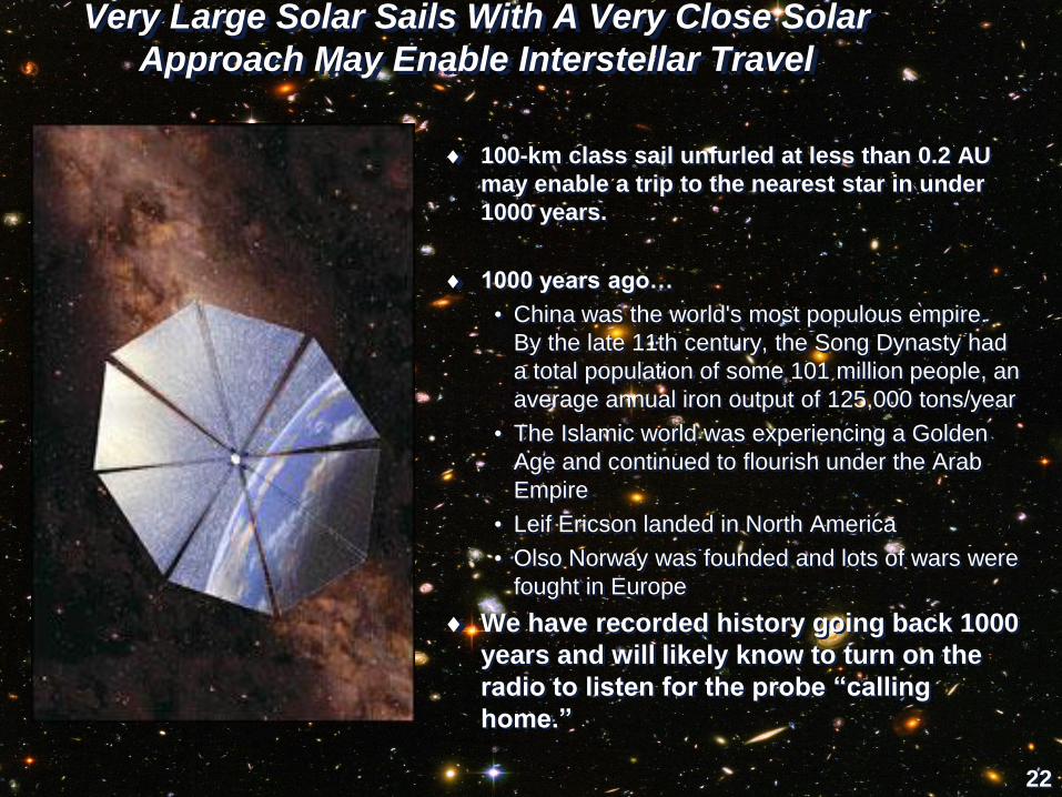
Very Large Solar Sails With A Very Close Solar
Approach May Enable Interstellar Travel
100-km class sail unfurled at less than 0.2 AU
may enable a trip to the nearest star in under
1000 years.
1000 years ago…
• China was the world's most populous empire.
By the late 11th century, the Song Dynasty had
a total population of some 101 million people, an
average annual iron output of 125,000 tons/year
• The Islamic world was experiencing a Golden
Age and continued to flourish under the Arab
Empire
• Leif Ericson landed in North America
• Olso Norway was founded and lots of wars were
fought in Europe
We have recorded history going back 1000
years and will likely know to turn on the
radio to listen for the probe “calling
home.”

23
~ 100-m DIA
= 10 g/m2
150 - 300-m DIA
= 1 - 2.5 g/m2
MID-TERM
SAIL DEMO
4000-m DIA
0.1 g/m 2
1-km DIA
= 0.1 g/m2
ADVANCED
SAIL DEMO and/or
HELIOSPHERE SCIENCE
• SOLAR POLAR IMAGER
• MERCURY ORBITER
• NON-KEPLERIAN EARTH ORBITS
TECH
DEV
TECH
DEV
TECH
DEV
TECH
DEV
TECH
DEV
INTERSTELLAR
MEDIUM EXPLORATION
TRAVEL WITHIN
SOLAR SYSTEM:
DAYS TO WEEKS
Geostorm67-m DIA
= 15 g/m2
(8 m film)
Solar Powered
Laser Powered
= Areal Density (Sail Mass/Sail Area)
4.5 LY
INTERSTELLAR
PROBE FLYBY
40 LY
INTERSTELLAR
PROBE
RENDEZVOUS
• INTERSTELLAR PROBE
• EUROPA LANDERS
• COMET SAMPLE RETURN
• OORT CLOUD
4-km DIA
= 0.1 g/m2
1000-km DIA
= 0.1 g/m2
NEAR-TERM
SAIL DEMO
40 - 70-m DIA
= 20 g/m2
Near-Term Solar Sail Applications Lead to
Interstellar Capability with Laser Sails

24
Light Sail
1000 km
Diameter
Transmitter
Optics
100 km
Diameter
Laser
(1.5µm)
2 L.Y. Coast
Rest
of Way
to Star
INTERSTELLAR FLYBY
1st Stage
(1000 km Dia.)
Accelerated
Out of System
2nd Stage (300 km Dia.)
Stops at Star
6 L.Y.
300 km
Diameter
Laser
(0.5µm)
INTERSTELLAR RENDEZVOUS
Light
Sail
Transmitter
Optics
• Advantages • Perform interstellar missions in < 50 years • Only competitor is antimatter • Use as a solar sail once in orbit about target • Use solar power satellite as driver for robotic flybys
• Disadvantages • Very high laser / microwave powers (0.1-1,000 TW) • Very large optics (100-1,000 km)
• Far-term concept, but one of the few ways to do ''fast'' interstellar missions
Interstellar Light Sail Concept

25
Laser Sails Are BIG

26
Types of Sail Designs
Square Sail Spinning Disk Sail Heliogyro

27
Spinning Solar SailDeployment Sequence

Solar Sail Technology – Many Players
NASA developed 80m class solar
sail propulsion systems to ~TRL-5/6
in the mid-2000’s
• Tested inner 20m sail core under
thermal vacuum conditions in 2005
JAXA is flying a 14m solar sail to
Venus (launched in 2010)
NASA is flying NanoSail-D subscale
solar sail prototype
The Planetary Society’s Cosmos-1
twice suffered launch vehicle
failure; LightSail-1 is their new
project
28

29
NASA Solar Sail Propulsion Technology Status
Technology Area Status:• Two solar sail technologies were designed, fabricated, and tested under
thermal vacuum conditions in 2005: 10 m system ground demonstrators were developed and tested in 2004/2005. 20 m system ground demonstrators designed, fabricated, and tested
• Developed and tested high-fidelity computational models, tools, and diagnostics.
• Multiple efforts completed: materials evaluation, optical properties, long-term environmental effects, charging issues, and assessment of smart adaptive structures.
30
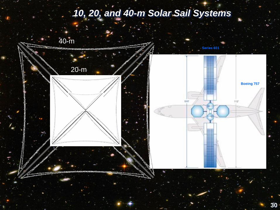
10, 20, and 40-m Solar Sail Systems
Boeing 757
Series 601
10-m
20-m
40-m
31
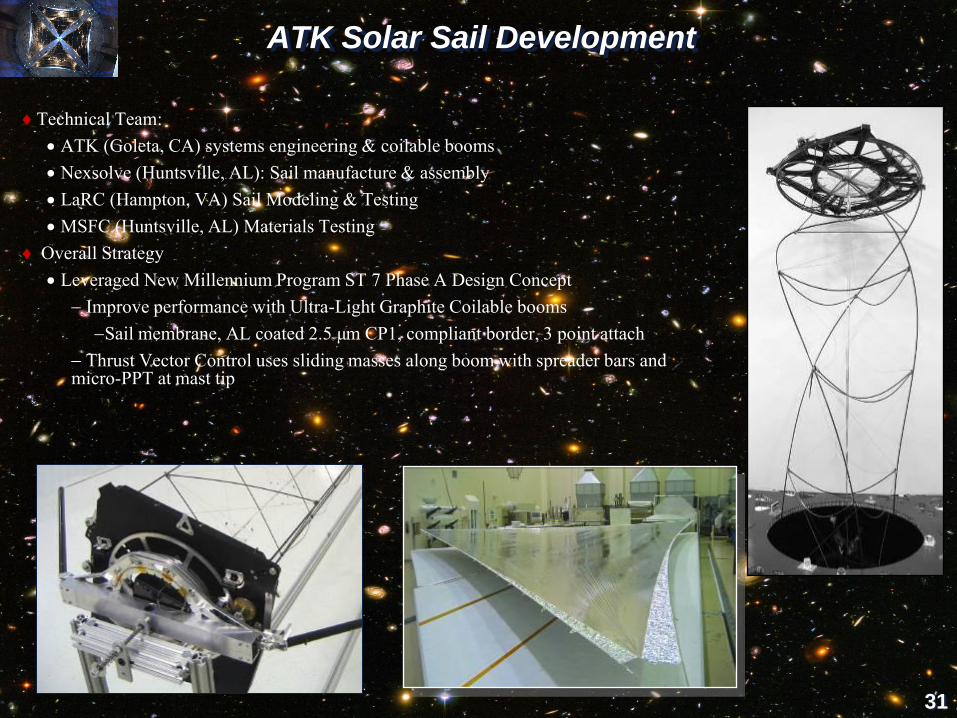
ATK Solar Sail Development
Technical Team:
ATK (Goleta, CA) systems engineering & coilable booms
Nexsolve (Huntsville, AL): Sail manufacture & assembly
LaRC (Hampton, VA) Sail Modeling & Testing
MSFC (Huntsville, AL) Materials Testing
Overall Strategy
Leveraged New Millennium Program ST 7 Phase A Design Concept
Improve performance with Ultra-Light Graphite Coilable booms
Sail membrane, AL coated 2.5 µm CP1, compliant border, 3 point attach
Thrust Vector Control uses sliding masses along boom with spreader bars and micro-PPT at mast tip

32
Longeron(.100-in. sq.)
Batten(Ø.070-in.)
Diagonal(Ø.009-in.)
CoilABLE Mast Linear Mass: ~ 70 g/mStowed CoilABLE
Ø20-in. (50.5 cm)
18.7-in.-tall(<0.55% of length)
Sail Thickness:
2.5 m CP1
Operating Temperature 16°C at .98 au
First Natural Frequency 0.02 Hz
Stowed Package 1.5 m dia. by 0.53 m
System Mass: 108 kg (w/ contingency)
Characteristic acceleration 0.76 mm/s2
0.34 mm/s2 with 130 kg SC
Cut-Away of
Stowed
Package
ATK Solar Sail Development, Continued
33
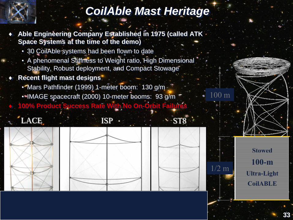
CoilAble Mast Heritage
Able Engineering Company Established in 1975 (called ATK
Space Systems at the time of the demo)
• 30 CoilAble systems had been flown to date
• A phenomenal Stiffness to Weight ratio, High Dimensional
Stability, Robust deployment, and Compact Stowage
Recent flight mast designs
• Mars Pathfinder (1999) 1-meter boom: 130 g/m
• IMAGE spacecraft (2000) 10-meter booms: 93 g/m
100% Product Success Rate With No On-Orbit Failures
Stowed
100-m
Ultra-Light
CoilABLE
1/2 m
100 m
M = 24.0 cm
LS/LD = 0.88%
rL = 34 g/m
M = 39.5 cm
LS/LD = 0.85%
rL = 70 g/m
M = 25.5 cm
LS/LD = 2.0%
rL = 240 g/m
ST8LACE ISP

34
Nexsolve Solar Sail Membrane Features
Membrane Design:4-quadrant planar sail
• Compliant Border interface between edge cable and membrane
• Shear insensitive, Cord/Material CTE mismatch insensitive
• Thermal Gradient insensitive
Sail Material: CP1 Polyimide• High Operating Temperature (>200o C)
• UV Stable
• Essentially Inert
• Soluble (Wet Process), modifiable with variety additives -
improve conductivity and thermal properties
• 2.5 micron polyimide
• Flight Proven --- flying on Numerous GEOCOM satellites
Sail Construction Methods: A gossamer film construction similar to gusseted, reflective
blankets flying on numerous GEOCOM satellites
• Scalable Construction Methods --- current system >20m
• Adhesive less Bonding Methods --- eliminates sticking and
contamination risks.
IMG_1123.J
PG Sail with Compliant
Border
FEM of Parobolic Edge
160 m2 of film per satellite.
Film Is 1 mil material supported
by 5 mil edge designs
SRS CNC Seaming System
Sail Production

35
ATK 20-m System Ground Demonstrator
ATK 20-M SGD CoilABLE MastsCentral Structure
Spreader Bar
Sail Membrane
Translating Mass
36
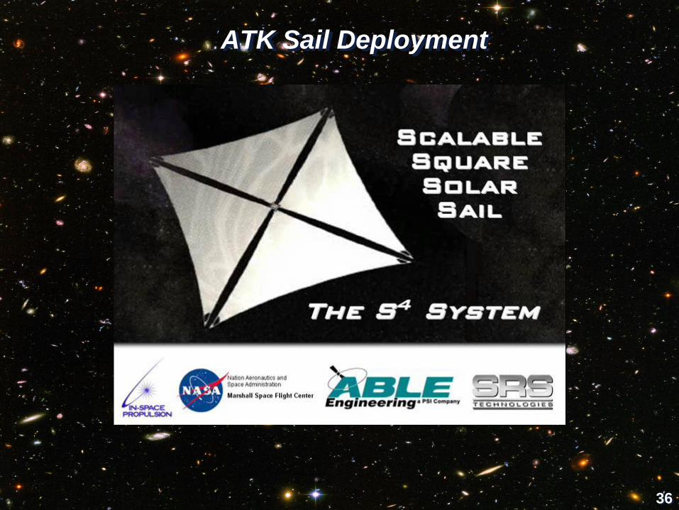
ATK Sail Deployment
37
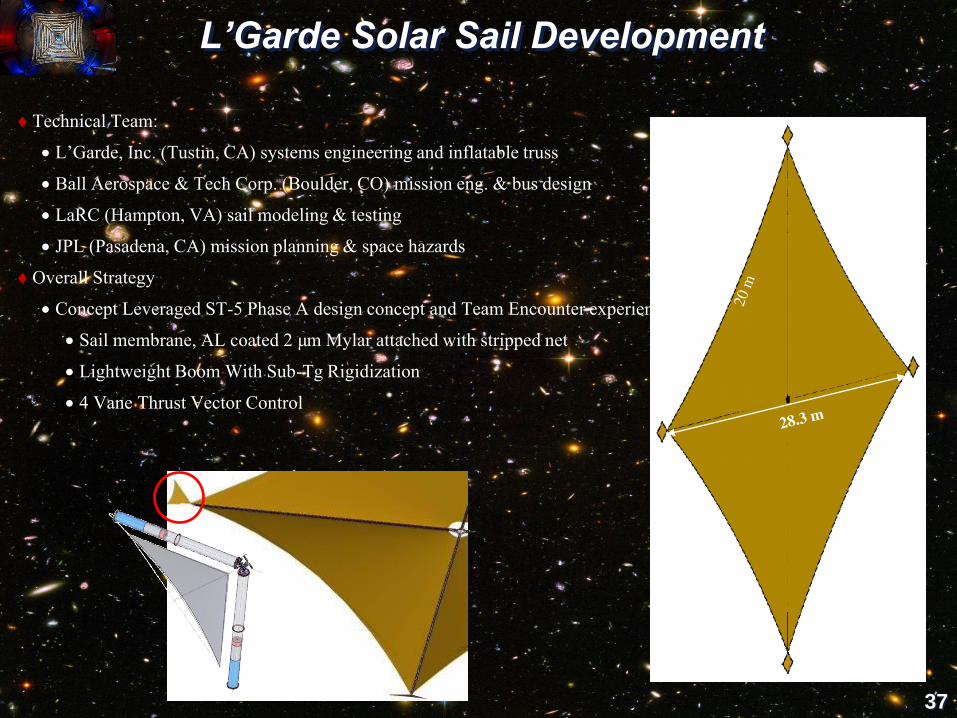
L’Garde Solar Sail Development
Technical Team:
L’Garde, Inc. (Tustin, CA) systems engineering and inflatable truss
Ball Aerospace & Tech Corp. (Boulder, CO) mission eng. & bus design
LaRC (Hampton, VA) sail modeling & testing
JPL (Pasadena, CA) mission planning & space hazards
Overall Strategy
Concept Leveraged ST-5 Phase A design concept and Team Encounter experience
Sail membrane, AL coated 2 µm Mylar attached with stripped net
Lightweight Boom With Sub-Tg Rigidization
4 Vane Thrust Vector Control

38
Beam Characteristics
Load bearing longitudinal uni-directional fibers• Fibers impregnated with resin (rigid below -20o C)• 0.48 AU design requires greater fiber density to withstand loads from the
increased solar fluxSpiral wrap
• Stabilizes longitudinal fibers• Allows over-pressurization for deployment anomalies
Bonded Kapton bladder and Mylar• Encapsulation "skin" carries shear• Aircraft fuselage like structure
Beam Structure• Sail structure is stressed for solar loading in one direction for mass
efficiency• Truss system comprised of mostly tension elements, minimal rigid
components• Highly mass efficient, ~36g/m linear density
Rigid
Spreader
Bars
Rigid Rings
Longeron Lines
Rigidizable
Boom
Solar
Flux
Stowed 7 m boom (~.5 m) Deployed 7 m boom
39
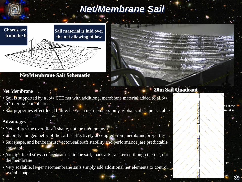
Net/Membrane Sail
20m Sail Quadrant
Net/Membrane Sail Schematic
Net Membrane
• Sail is supported by a low CTE net with additional membrane material added to allow
for thermal compliance
• Sail properties effect local billow between net members only, global sail shape is stable
Advantages
• Net defines the overall sail shape, not the membrane
• Stability and geometry of the sail is effectively decoupled from membrane properties
• Sail shape, and hence thrust vector, sailcraft stability and performance, are predictable
and stable
• No high local stress concentrations in the sail, loads are transferred though the net, not
the membrane
• Very scalable, larger net/membrane sails simply add additional net elements to control
overall shape
Chords are suspended
from the boom ringsSail material is laid over
the net allowing billow
Each stripe adds some
load to the beam, at a
45° angle:
low stress
concentrations
Beam load
accumulates
toward base
Tapered boom is
largest at the
base, where the
load is the highest

40
L’Garde 20-m System Ground Demonstrator
20-M SGD
Sail Membrane
Tip Vane
Vane Mechanism Stowed Configuration
Tip Mandrel
Inflatable Beams

41
L’Garde Inflatable Sail Deployment

42
Solar Sail Subsystem Development
Solar Sail Spaceflight Simulation Software (S5)
Developed an integrated simulation and
analysis software tool for optimal design of
solar sail trajectories and for evaluation of
guidance navigation and control strategies.
Solar radiation
pressureAcceleration
Control torque
Sailcraft trajectory
Optical Diagnostic System (ODS)
Developed a ground integrated
instrumentation package to allow
measurement of sail shape, tension and
temperature; boom & sail vibration modes
and stress; and deployment monitoring.

43
Solar Sail Subsystem Development– cont.
Material Testing
Characterized engineering performance of
candidate SS materials at .5 and 1 AU,
gauging material property tolerances after
exposure to simulated mission-specific
charged-particle and micrometeoroid
environments.
Development of a Lightweight Robust SACS
and a Software Toolkit for Solar Sails
Developed of a highly integrated, low cost, low
mass, low volume, and low power attitude
determination and control system and develop
a high-fidelity multi-body modeling and
simulation software toolkit.
Samples prior to UV exposure

44
Solar Sail Subsystem Development– cont.
Sail Charging Analysis
Developed environmental and sail configuration
models and design guideline criteria for solar sails.
Conduct laboratory assessment of potential for
destructive charging fields and arcing events within
the sail and surrounding environment.
Plasma Flow Model of sail
in the solar wind with the
potentials normalized by
0.25 Te
Smart Adaptive
Structures
Identified nonlinear
mechanism for
existing 40 meter
coilable boom. Assess
potential for control
structures
interactions.
Mounted SAFE Mast Canister System

45
TRL Assessment Process Flowchart
Solar Polar ImagerHeliostorm
L’Garde
On-Orbit Environment
Launch Environment
Ground Environment
Relevant Environment
Definition
TRL 1-9
Technology Readiness
Level (TRL) Definitions/
Requirements
TRL Assessment Tool
ATK
System Ground
Demonstrator (SGD)
Design, Analyses,
Fabrication, Testing
(10 Meter and 20
Meter)
Technology Readiness
Level (TRL)
Assessment
Technology Gaps
TRL Determination
Initial Application
Missions
Input
Input
Technology
Assessment Group
(TAG)
46
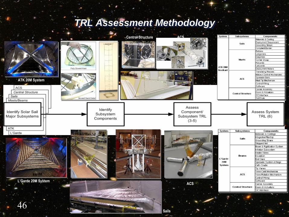
TRL Assessment Methodology
ATK 20M System
Central Structure
Masts
Beams
Sails
Sails
Central Structure
L’Garde 20M System
ACS
ACS

47
TRL Assessment Results Comparison
Vendor
Post 10M
TRL 5
Completion
Average
Post 20M
TRL 5
Completion
Average
Post 10M
TRL 6
Completion
Average
Post 20M
TRL 6
Completion
Average
ATK 76% 89% 60% 86%
L’Garde 75% 84% 68% 78%
ATK L’Garde

48
NanoSail-D Demonstration Solar Sail
Mission Description
• 10 m2 sail
• Made from tested ground
demonstrator hardware
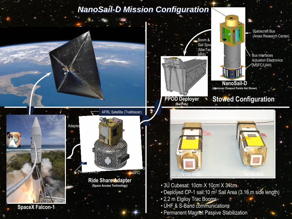
SpaceX Falcon-1
PPOD Deployer(Cal-Poly)
NanoSail-D(Aluminum Closeout Panels Not Shown)
Ride Share Adapter(Space Access Technology)
Spacecraft Bus
(Ames Research Center)Boom &
Sail Spool
(ManTech
SRS) Bus interfaces
Actuation Electronics
(MSFC/UAH)
NanoSail-D
(MSFC)
Stowed Configuration
PreSat (ARC)
NanoSail-D Mission Configuration
• 3U Cubesat: 10cm X 10cm X 34cm
• Deployed CP-1 sail:10 m2 Sail Area (3.16 m side length)
• 2.2 m Elgiloy Trac Booms
• UHF & S-Band communications
• Permanent Magnet Passive Stabilization
AFRL Satellite (Trailblazer)
NSD-001NSD-002
Adapter
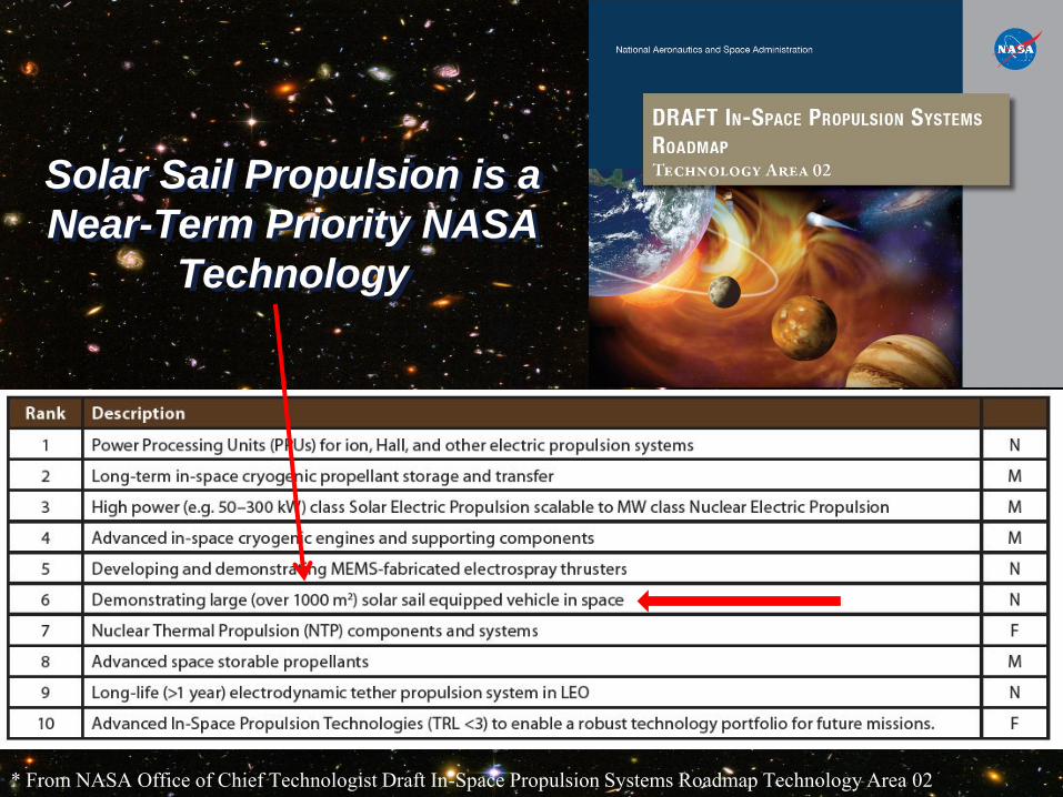
Solar Sail Propulsion is a
Near-Term Priority NASA
Technology
* From NASA Office of Chief Technologist Draft In-Space Propulsion Systems Roadmap Technology Area 02

Interplanetary Kite-craft Accelerated by Radiation Of the Sun (IKAROS)
• IKAROS was launched on May 21, 2010
•The Japan Aerospace Exploration Agency (JAXA) began to
deploy the solar sail on June 3.
• IKAROS has demonstrated deployment of a solar sailcraft,
acceleration by photon pressure and attitude control
• Deployment was by centrifugal force
•Sail membrane is 7.5 mm thick
.
Configuration / Body Diam. 1.6 m x Height 0.8 m (Cylinder shape)
Configuration / Membrane Square 14 m and diagonal 20 m
Weight Mass at liftoff: about 310 kg

LightSail-1 (The Planetary Society) Status
52
Cubesat design
• 4.5 kg
• Two 2-megapixel cameras
• Four sun sensors
• Six accelerometers for measuring solar
acceleration
Sail Material: aluminized 4.5 micron
Mylar film
32 square meters solar sail area fully
deployed
2011 planned launch
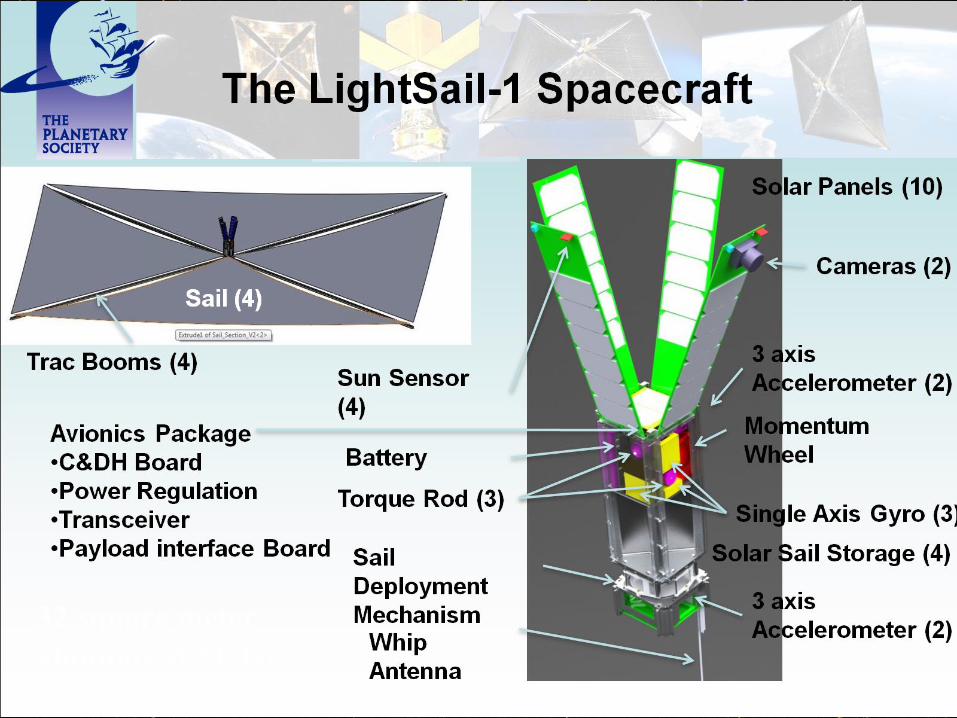
53
32 square meter
aluminized Mylar
sail

54

Solar Sail Technology Status
JAXA has taken solar sail propulsion to TRL-7
NASA’s large first generation solar sails are a
mature technology ready for flight validation
and subsequent mission implementation
• Unless space validation is initiated soon, the TRL will
begin to slip
• Based on 2006 ST-9 studies, a validation mission can be
flown for under $200M
Cubesat scale sails are a mature technology for
selected applications
55