1
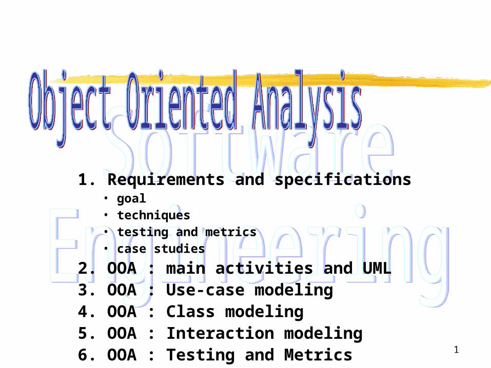
1. Requirements and specifications• goal• techniques• testing and metrics• case studies
2. OOA : main activities and UML3. OOA : Use-case modeling4. OOA : Class modeling5. OOA : Interaction modeling6. OOA : Testing and Metrics
2
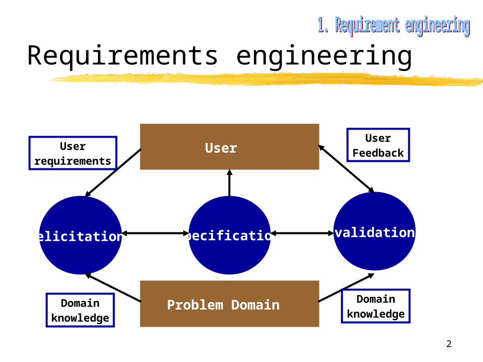
Requirements engineering
User
Problem Domain
elicitation specification validation
Userrequirements
Domainknowledge
Domainknowledge
UserFeedback
3
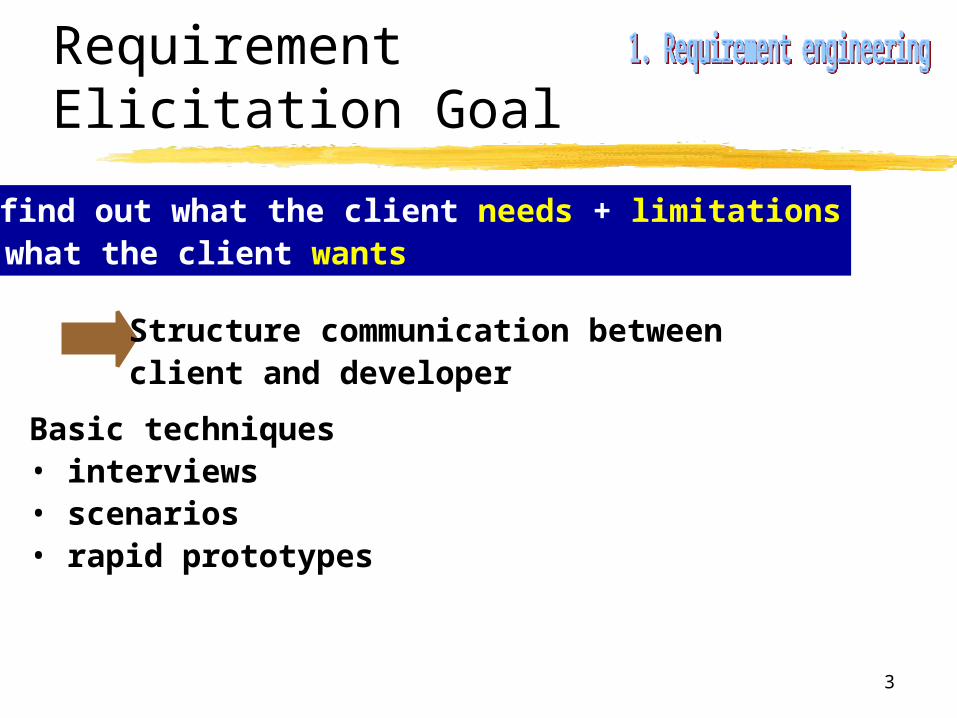
Requirement Elicitation Goal
= find out what the client needs + limitations what the client wants
Structure communication between client and developer
Basic techniques• interviews• scenarios• rapid prototypes
4
Requirement Elicitation techniques
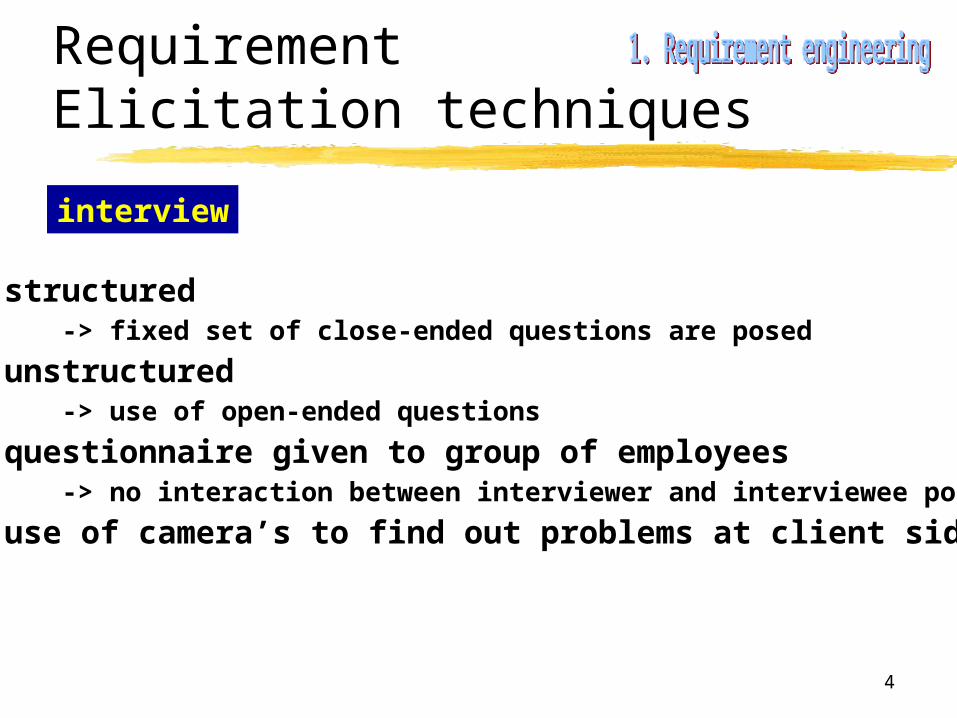
interview
• structured -> fixed set of close-ended questions are posed
• unstructured-> use of open-ended questions
• questionnaire given to group of employees-> no interaction between interviewer and interviewee possible
• use of camera’s to find out problems at client side

5
Requirement Elicitation techniques
scenarios
= a set of “if … then”-clauses
Representations • list actions associated with scenario• give a sequence of expected screen shots in response to action

6
Requirement Elicitation techniques
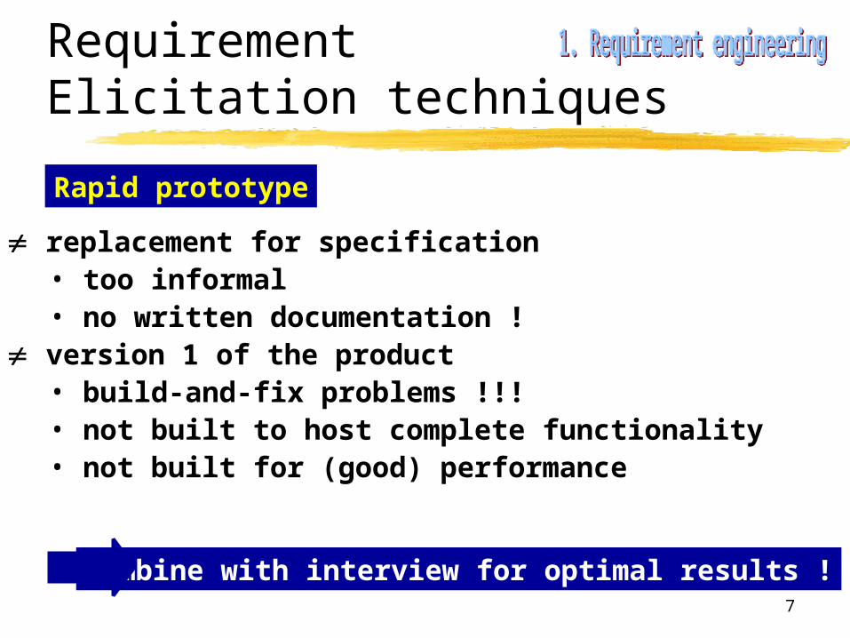
Rapid prototype
build-and-fix for the prototype !
put together a working product, implementing asubset of the expected functionality
• include functionality visible to the usere.g. input screens, reports, ...
• omit complexity not eliciting needse.g. input checks, file updates, consistency checks, layout, ...
modify prototype until client and developer agreethat all client needs are incorporated
7
Requirement Elicitation techniques
Rapid prototype
replacement for specification• too informal• no written documentation !
version 1 of the product• build-and-fix problems !!!• not built to host complete functionality• not built for (good) performance
Combine with interview for optimal results !
8
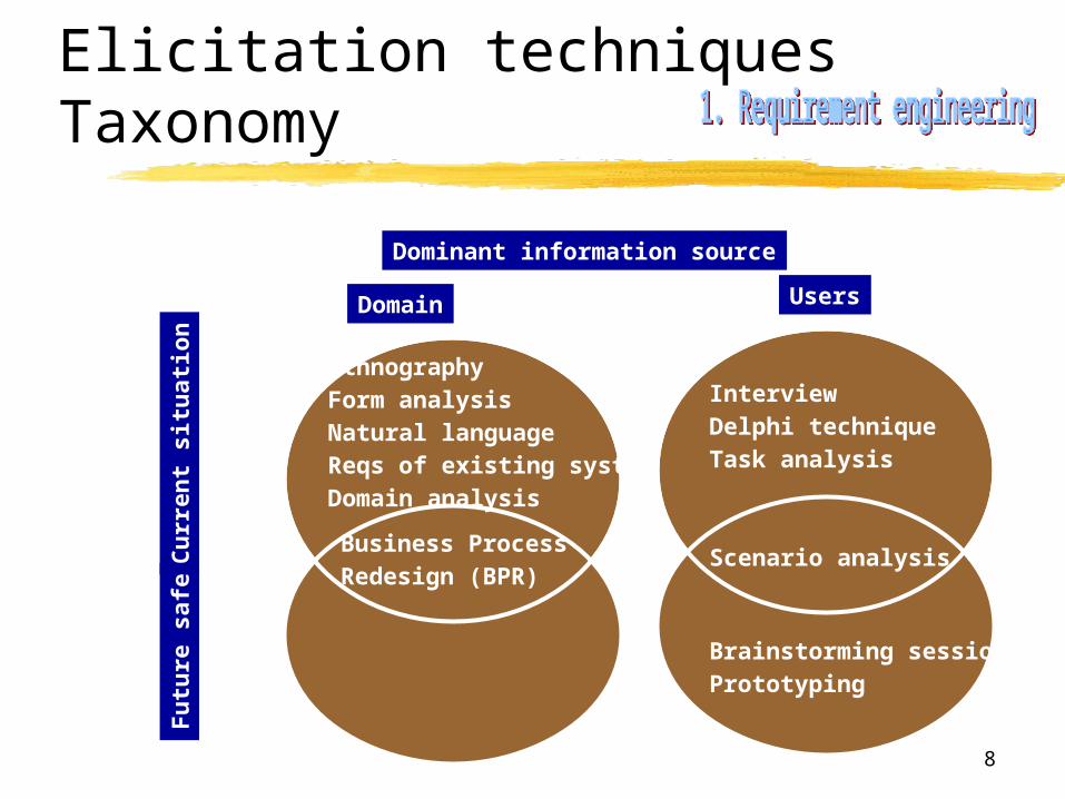
Elicitation techniquesTaxonomy
Dominant information source
UsersDomain
Cu
rren
t si
tuat
ion
Fu
ture
saf
e
InterviewDelphi techniqueTask analysis
Scenario analysis
Brainstorming sessionPrototyping
EthnographyForm analysisNatural language Reqs of existing systemDomain analysis
Business Process Redesign (BPR)

9
Requirement specification
1. Introduction
1. Purpose
2. Scope
3. Definitions, acronyms and abbreviations
4. References
5. Overview
2. Overall Description
1. Product Perspective
2. Product Functions
3. User characteristics
4. Constraints
5. Assumptions and dependencies
6. Requirement subsets
3. Specific Requirements

10
Requirement specification
3. Specific Requirements
3.1 External interface requirements
3.1.1 User interfaces
3.1.2 Hardware interfaces
3.1.3 Software interfaces
3.1.4 Communication interfaces
3.2 Functional requirements
3.2.1 User class 1
3.2.1.1 Functional Requirement 1.1
3.2.1.2 Functional Requirement 1.2
…
3.2.2 User class 2
…
3.3 Performance requirements
3.4 Design constraints
3.5 Software system attributes
3.6 Other requirements
11
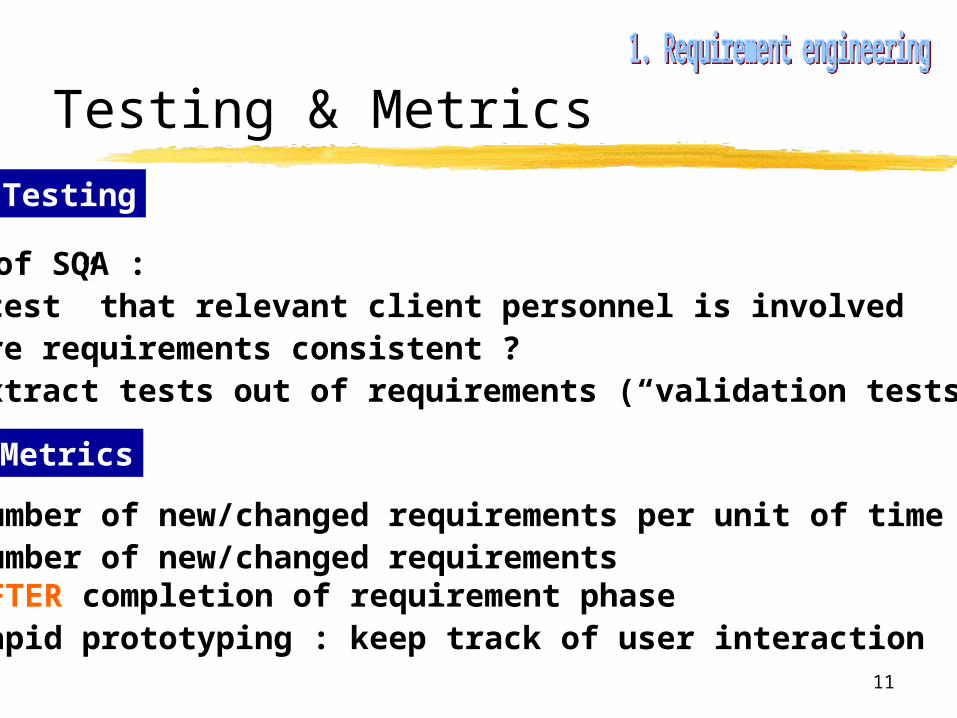
Testing & Metrics
role of SQA : • “test” that relevant client personnel is involved• are requirements consistent ?• extract tests out of requirements (“validation tests”)
Testing
Metrics
• number of new/changed requirements per unit of time• number of new/changed requirements AFTER completion of requirement phase• rapid prototyping : keep track of user interaction
12
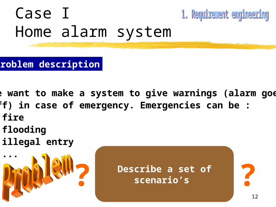
Case I Home alarm system
Problem description
We want to make a system to give warnings (alarm goesoff) in case of emergency. Emergencies can be :• fire• flooding• illegal entry• ...
Describe a set of scenario’s ??

13
Case II The (in)famous elevator problem
Problem description
Software to control an elevator is requested. The elevatoris to serve N floors, and has two types of control buttons :• buttons in the elevator : to select destination floor• buttons in the hall : to request an “elevator service”
Describe a set of scenario’s ??
14
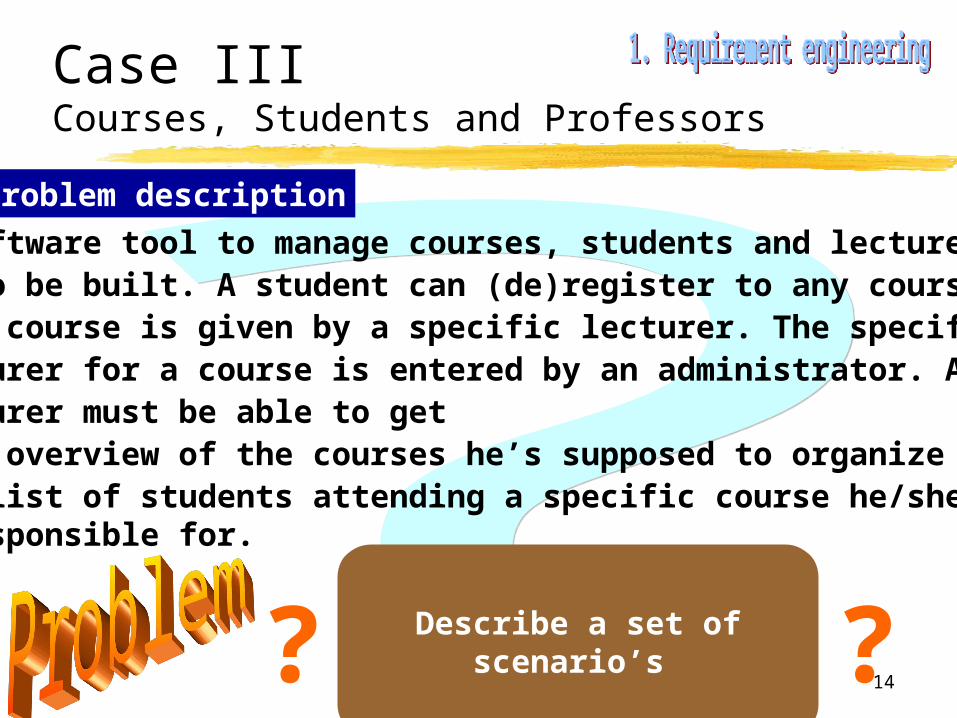
Case III Courses, Students and Professors
Problem description
A software tool to manage courses, students and lecturersis to be built. A student can (de)register to any course, andeach course is given by a specific lecturer. The specificlecturer for a course is entered by an administrator. Anylecturer must be able to get - an overview of the courses he’s supposed to organize and- a list of students attending a specific course he/she is responsible for.
Describe a set of scenario’s ??

15
Goal of OOA
• specify the externals of the product precisely (= specification technique)
• architectural design (class and object identification)
How to do it ?
(1) formalize basic requirements (user-developer)(2) identification of classes(3) identification of class hierarchy(4) find connections between objects(5) modeling of object behavior

16
UML ?Visual modeling of software
Several diagrams to model different aspectsof the software under construction
(1) formalize basic requirements
(2) identification of classes
(3) identification of class hierarchy
(4) find connections between objects
(5) modeling of object behavior
Use-case diagrams
(CRC-modeling)
State diagrams
Class diagrams
Interaction diagrams

17
Concept
Goal
Present requirements as seen from the userin a diagram, unambiguously
= user model view
Use-case diagram =Actor + use-cases
• define functional requirements of the system• describe clear and unambiguously interaction between user and system• provide basis for validation testing
18
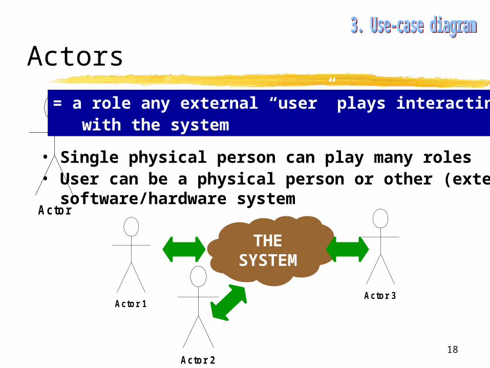
Actors
Actor
= a role any external “user” plays interacting with the system
• Single physical person can play many roles• User can be a physical person or other (external) software/hardware system
THE SYSTEM
Actor 1Actor 3
Actor 2

19
Case IIICourses, Students and Professors
Find the actors !
CourseAdministration
?Actor

20
Case IIICourses, Students and Professors
CourseAdministration
Student
Adm inistrator
Professor
21
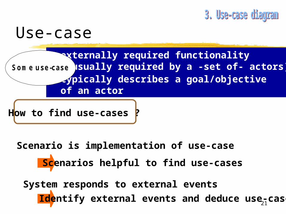
Use-case= externally required functionality (usually required by a -set of- actors)• typically describes a goal/objective of an actor
Som e use-case
Scenario is implementation of use-case
Scenarios helpful to find use-cases
How to find use-cases ?
System responds to external events
Identify external events and deduce use-cases
22
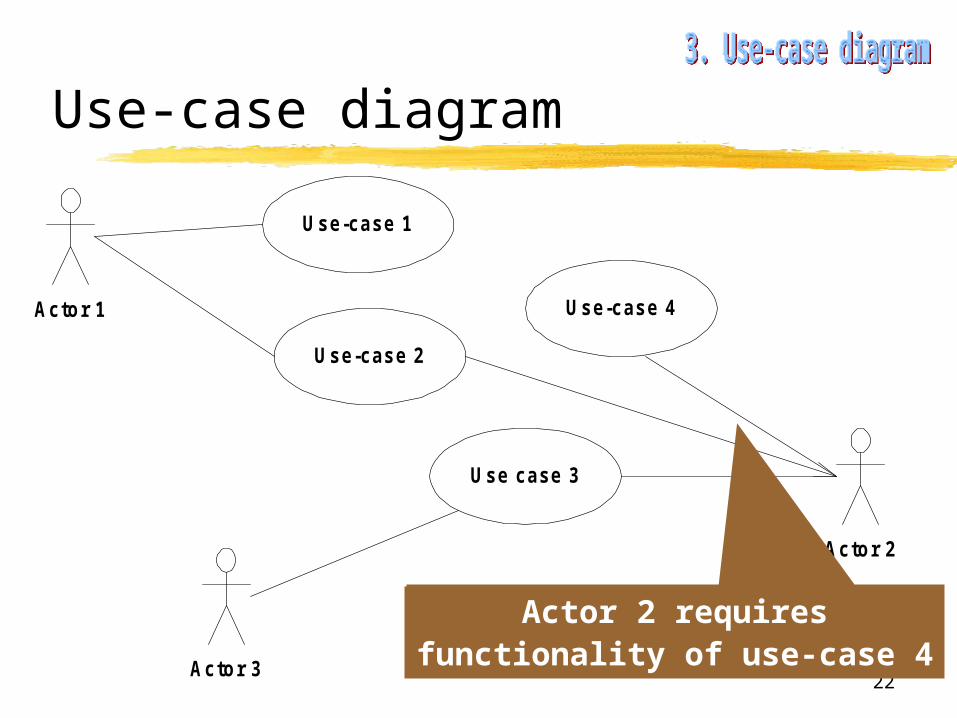
Use-case diagram
Use-case 1
Use-case 2
Use case 3
Use-case 4Actor 1
Actor 2
Actor 3
Actor 2 requiresfunctionality of use-case 4

23
Som e use-case
Case IIICourses, Students and Professors
Find use-cases !?
Actor
Actor
Actor

24
Case IIICourses, Students and Professors
Student
Professor
Administrator
Register tocourse
Deregister tocourse
View class forspecific course
View list ofow n courses
View allstudent lists Change course-
professor couple
View allcourses
25
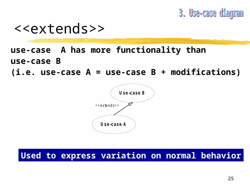
<<extends>>use-case A has more functionality thanuse-case B (i.e. use-case A = use-case B + modifications)
Use-case B
Use-case A
<<extends>>
Used to express variation on normal behavior
26
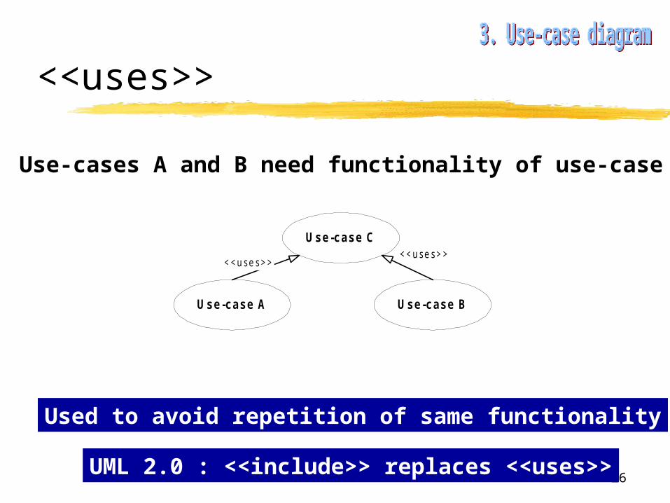
<<uses>>
Use-cases A and B need functionality of use-case C
Used to avoid repetition of same functionality
Use-case C
Use-case A Use-case B
<<uses>><<uses>>
UML 2.0 : <<include>> replaces <<uses>>
27
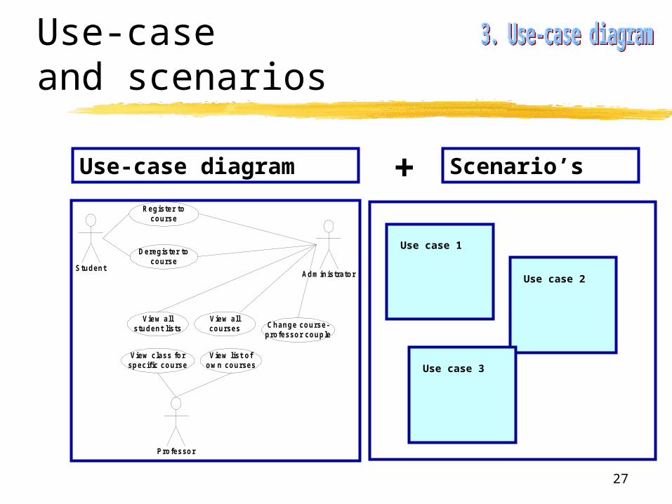
Use-caseand scenarios
Use-case diagram Scenario’s
Student
Professor
Administrator
Register tocourse
Deregister tocourse
View class forspecific course
View list ofow n courses
View allstudent lists Change course-
professor couple
View allcourses
+
Use case 1
Use case 2
Use case 3

28
Use-caseand scenarios
Use case 1
Use case title
Main Success Scenario
1. Step 1
2. Step 2
…
Extensions<MSS-step> [condition for alternative]
.1 : Step 1
.2 : Step 2
. : …
.X : return to MSS step …
<MSS-step> [ …]
…
Pre-conditions
Post-conditions
Triggers
29
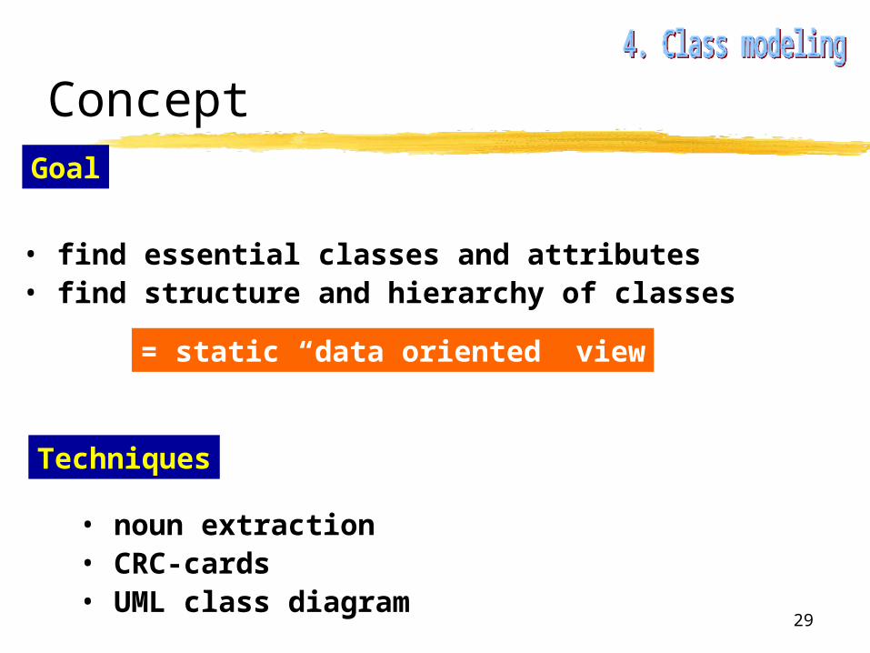
Concept
• find essential classes and attributes• find structure and hierarchy of classes
Goal
= static “data oriented” view
Techniques
• noun extraction• CRC-cards• UML class diagram
30
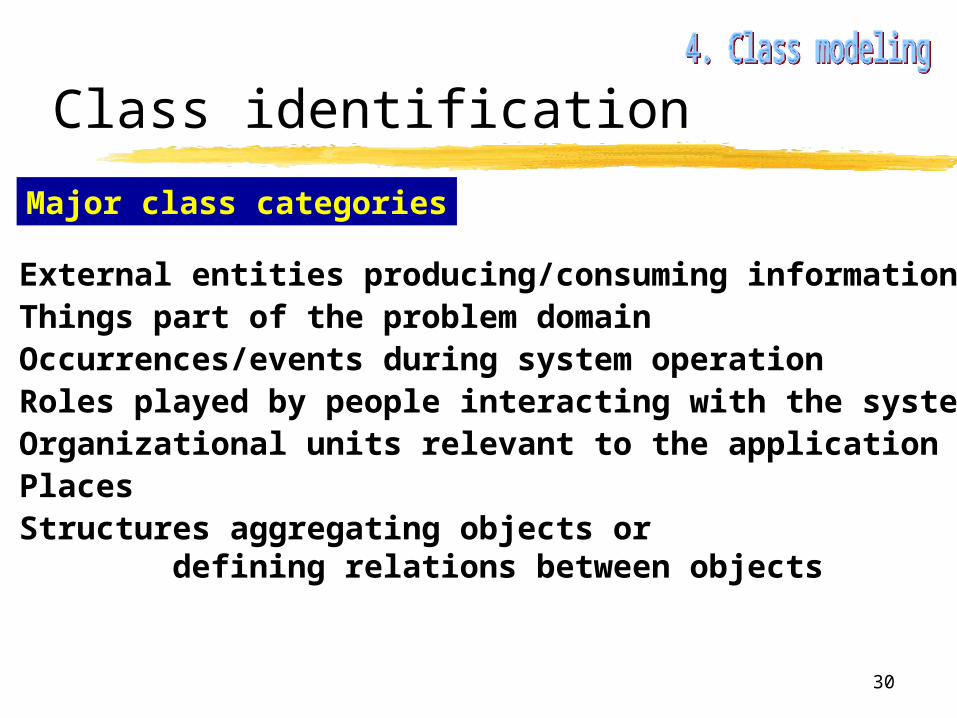
Class identification
Major class categories
• External entities producing/consuming information• Things part of the problem domain• Occurrences/events during system operation• Roles played by people interacting with the system• Organizational units relevant to the application• Places• Structures aggregating objects or
defining relations between objects

31
Class identification
Noun extraction
• Make a small text describing the problem, together with major requirements (10-20 lines).• Isolate all nouns from this text.
class-candidates
Remove :• nouns relating to non-physical, abstract entities• nouns relating to physical entities outside the problem domain
Only first indication !

32
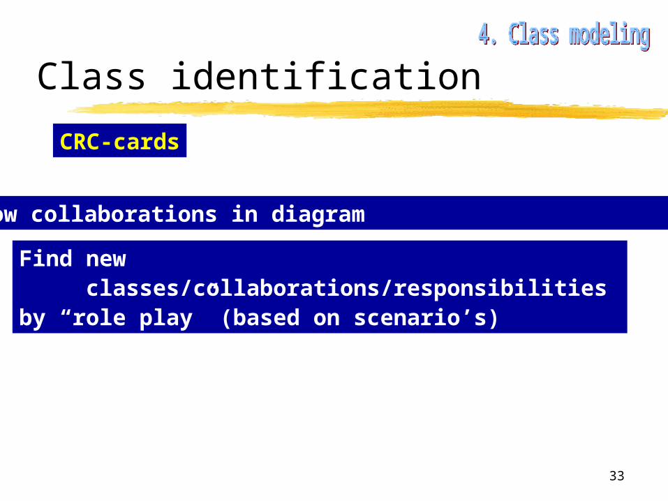
Class identification
CRC-cards
For each class fill in form
= Class-Responsibility-collaboration card
responsibilities : collaborations :
Class name :
Class characteristic :
Class type :
Describe the functionalityof the class
List other classes neededto achieve this functionality
33
Class identification
CRC-cards
Show collaborations in diagram
Find new classes/collaborations/responsibilities
by “role play” (based on scenario’s)

34
Case IIICourses, Students and Professors
Include password based authentication.All users identified by a unique number.• Update use-case diagram !
Identify classes by :• writing small text (10-20 lines)• noun extraction
35
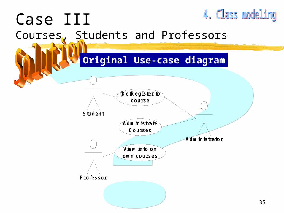
Case IIICourses, Students and Professors
Original Use-case diagram
Student
Professor
Administrator
(De)Register tocourse
View info onow n courses
AdministrateCourses

36
Case IIICourses, Students and Professors
Updated Use-case diagram
Student
Professor
Administrator
(De)Register tocourse
View info onow n courses
AdministrateCourses
AuthenticateUser
ChangeUser Passw ord
ChangeOw n Passw ord
<<uses>>
<<uses>>
<<uses>>
<<uses>>
<<uses>>

37
Case IIICourses, Students and Professors
A system to administrate courses is to be constructed. A userrequesting/supplying information from/to the system must identify himself using a password, which is checked. If found OK,the user gets access to the system and sees a menu.Each user has a unique identification number.The administrator of the system is responsible for defining thecourse-instructor relationship, and has essentially access to allinformation in the system (read and write).Students can register or deregister for any course. A professor canget a list of students for a specific course he teaches, and can alsoget a list of courses he teaches.
Descriptive text (10-20 lines)

38
Case IIICourses, Students and Professors
A system to administrate courses is to be constructed. A userrequesting/supplying information from/to the system must
identify himself using a password, which is checked. If found OK,
the user gets access to the system and sees a menu.
Each user has a unique identification number.
The administrator of the system is responsible for defining the
course-instructor relationship, and has essentially access to all
information in the system (read and write).
Students can register or deregister for any course. A professor can
get a list of students for a specific course he teaches, and can also
get a list of courses he teaches.
Extract nouns

39
Case IIICourses, Students and Professors
Candidate classes
SystemCourseUserInformationPasswordAccessAdministratorInstructorRelationshipStudentProfessorListNumberMenu
Abstract
Abstract
Abstract
Existing class (Vector or [ ])
SAME
CourseAdministration
IDNumber
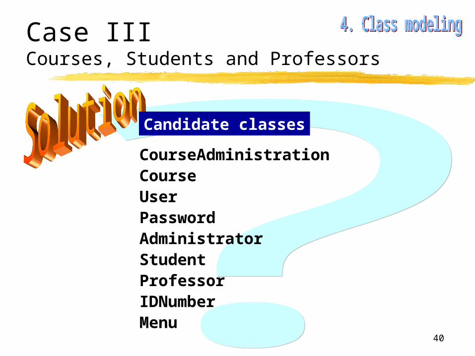
40
Case IIICourses, Students and Professors
Candidate classes
CourseAdministrationCourseUserPasswordAdministratorStudentProfessorIDNumberMenu
41
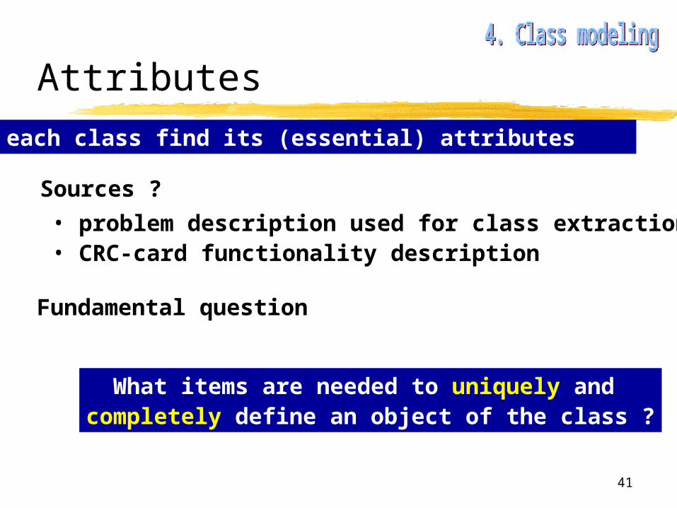
Attributes
For each class find its (essential) attributes
Sources ?
• problem description used for class extraction• CRC-card functionality description
Fundamental question
What items are needed to uniquely and completely define an object of the class ?
42
Case IIICourses, Students and Professors
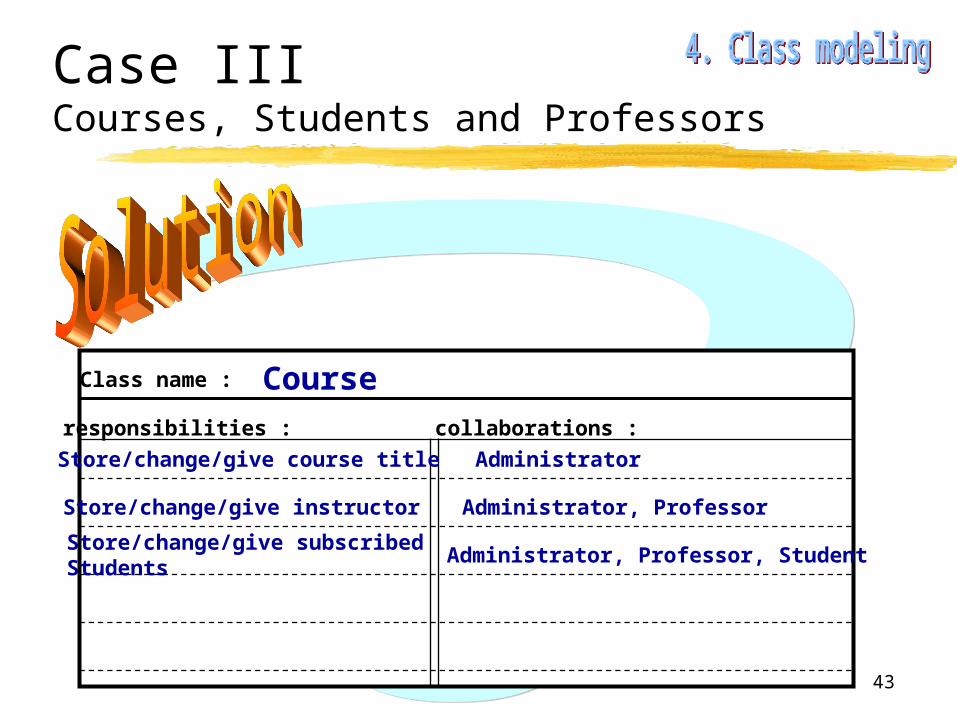
Make a CRC-card for the Course candidate classand find attributes.
43
Case IIICourses, Students and Professors
responsibilities : collaborations :
Class name : Course
Store/change/give course title
Store/change/give instructor
Store/change/give subscribed Students
Administrator
Administrator, Professor
Administrator, Professor, Student
44
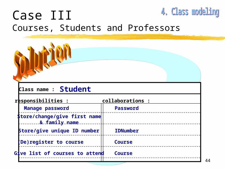
Case IIICourses, Students and Professors
responsibilities : collaborations :
Class name : Student
Manage password
Store/change/give first name& family name
Store/give unique ID number
Password
IDNumber
(De)register to course Course
Give list of courses to attend Course
45
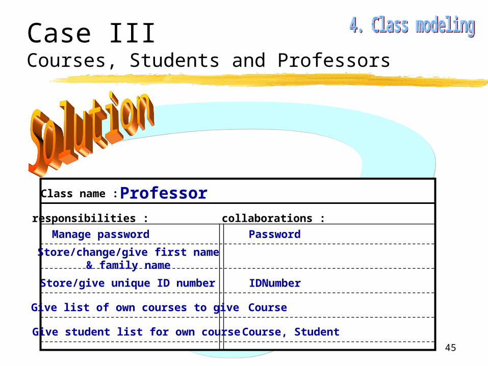
Case IIICourses, Students and Professors
responsibilities : collaborations :
Class name : Professor
Manage password
Store/change/give first name& family name
Store/give unique ID number
Password
IDNumber
Give list of own courses to give Course
Give student list for own course Course, Student
46
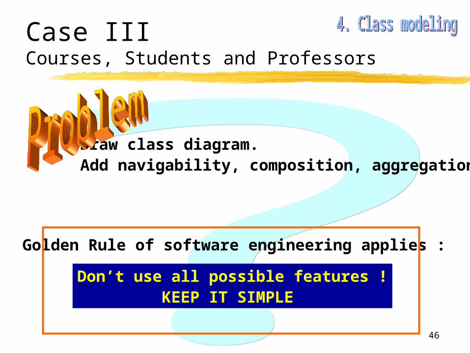
Case IIICourses, Students and Professors
Draw class diagram.Add navigability, composition, aggregation.
Don’t use all possible features !KEEP IT SIMPLE
Golden Rule of software engineering applies :
47
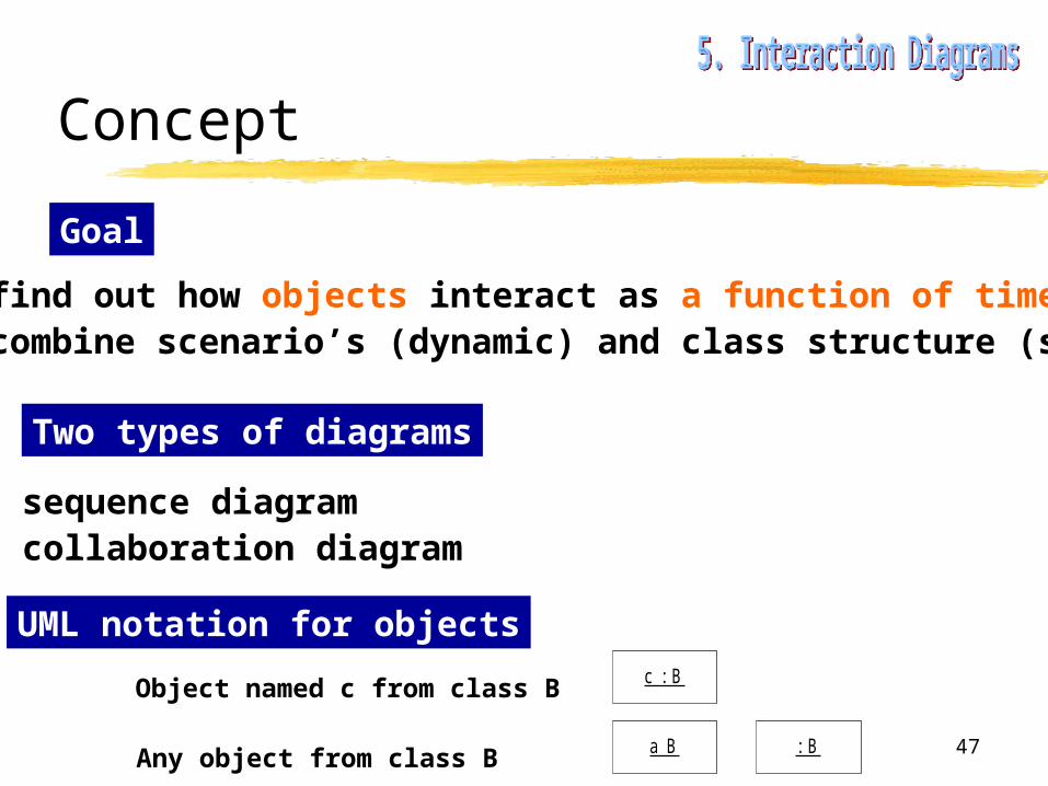
Concept
Goal
• to find out how objects interact as a function of time• to combine scenario’s (dynamic) and class structure (static)
Two types of diagrams
• sequence diagram• collaboration diagram
UML notation for objectsc : BObject named c from class B
Any object from class B a B : B
48
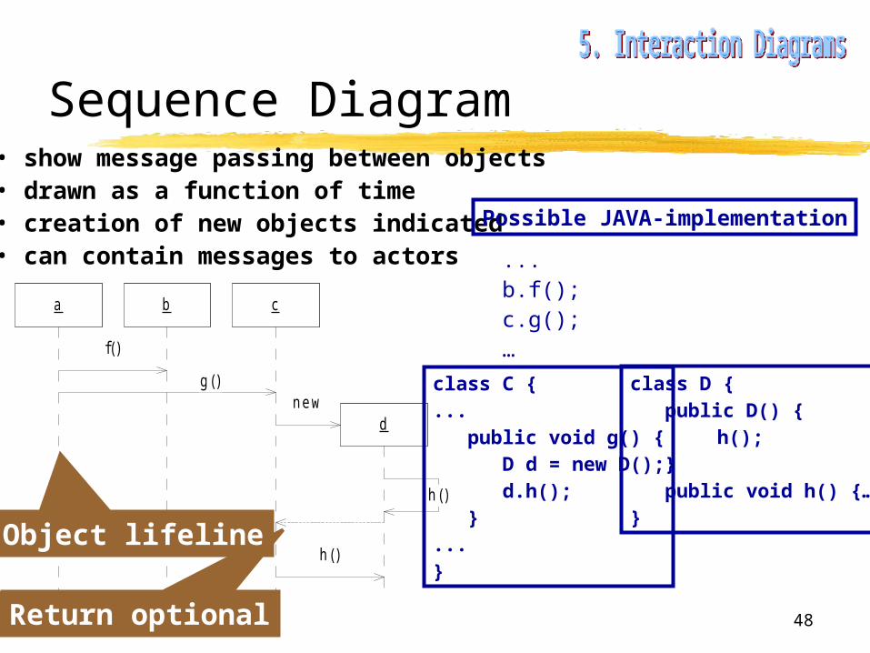
Sequence Diagram• show message passing between objects• drawn as a function of time• creation of new objects indicated• can contain messages to actors
a b c
d
f()
g()new
h()
h()
Possible JAVA-implementation
...b.f();c.g();…
class D { public D() {
h(); } public void h() {…}}
class C {... public void g() { D d = new D(); d.h(); }...}
Return optional
Object lifeline
49
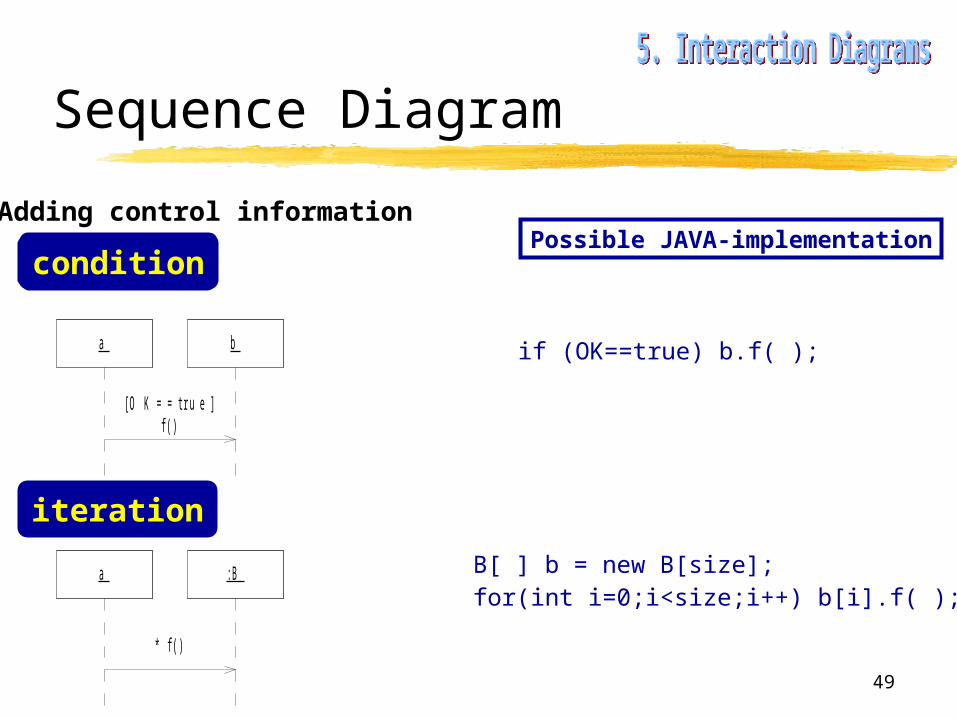
Sequence Diagram
Adding control informationPossible JAVA-implementation
if (OK==true) b.f( );a b
[O K==true]f()
condition
iteration
a :B
* f()
B[ ] b = new B[size];for(int i=0;i<size;i++) b[i].f( );

50
Case IIICourses, Students and Professors
Make a scenario for password authenticationTransform into a sequence diagram.List consequences to CRC-card for Password class.

51
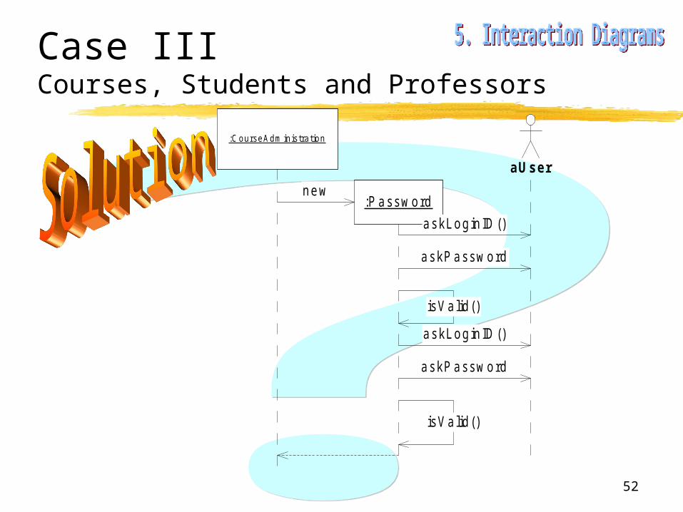
Case IIICourses, Students and Professors
Authentication scenario
0. System starts up, CourseAdministration object created1. Password object created2. Password object asks user for login ID and password3. Password object checks validity -> not valid4. Password object asks user for login ID and password5. Password object checks validity -> valid6. Password object returns
52
Case IIICourses, Students and Professors
:CourseAdm inistration
aUser
new:P assword
askLogin ID ()
askP assword
isV a lid ()
askLogin ID ()
askP assword
isV a lid ()
53
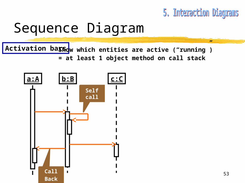
Sequence DiagramActivation bars Show which entities are active (“running”)
= at least 1 object method on call stack
a:A b:B c:C
Self call
CallBack

54
Sequence DiagramFound messages
Destruction
= first message from causing the sequence diagram to “start”
a:A b:B
b:B
implicit
b:B
explicit
55
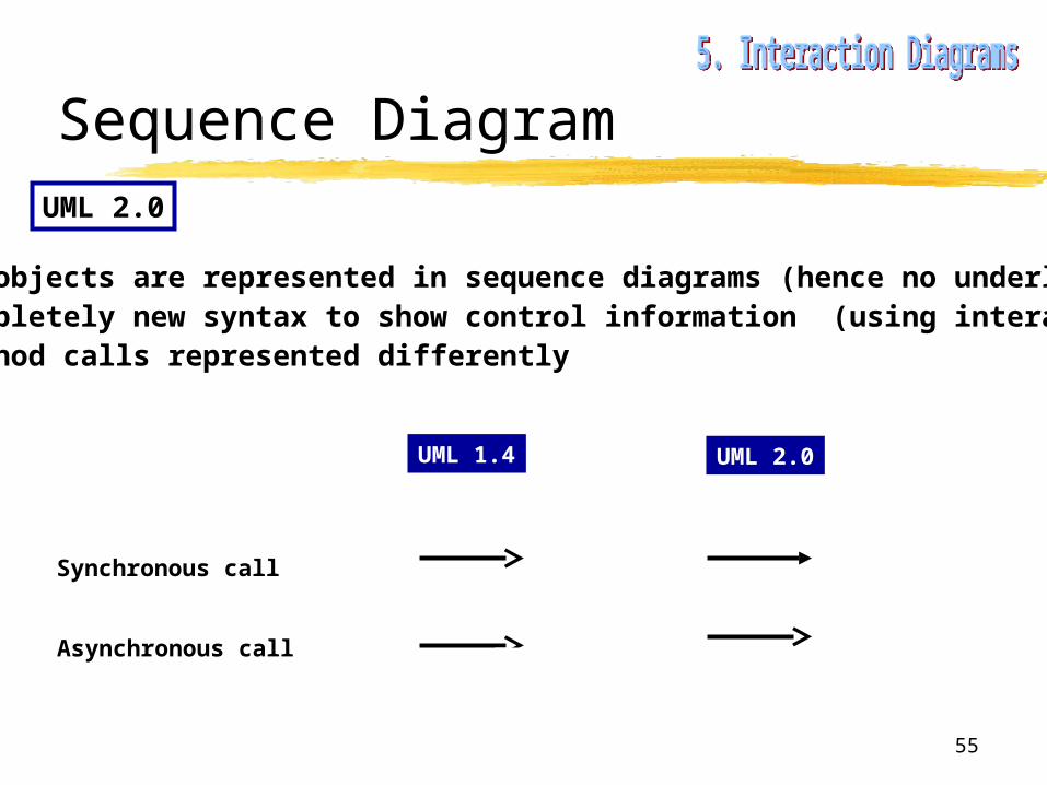
Sequence DiagramUML 2.0
• no objects are represented in sequence diagrams (hence no underlining)• completely new syntax to show control information (using interaction frames)• method calls represented differently
UML 1.4 UML 2.0
Synchronous call
Asynchronous call

56
Collaboration Diagram• shows messages between objects• messages numbered to show sequence• more layout freedom (used to clarify relation between objects)• messages can be labeled with control info (condition and iteration)
a
b
c
d
1:f()
2 :g()
3 :new5:h()
4 :h()
UML 2.0 : “Communication Diagrams”

57
Collaboration Diagram
Alternative numbering scheme to show hierarchy of messages
a
b
c
d
1:f()
2 :g()
2 .1 :new2.2 :h()
2 .1 .1 :h()

58
Goal & Concept
To view the state of an object during the lifetime of the system
Diagram consists of :• object states• transitions (due to events)
Transitions are labeled Event [Guard] / Action
States are labeled do / activity
Not interruptible
Can be interrupted

59
Example Password authentication
Checking IDdo / ask ID
H start
[invalid ID ]
[Valid ID ]
CheckingPassw ord
do / askPassWord
[Invalid Password]
AuthenticationOK
[Valid Passord]

60
Specification
iterating use-casestatic modelingdynamic modeling
Specification document
= diagrams + rigorous description
61
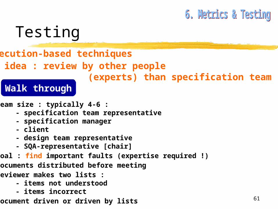
Testing• Nonexecution-based techniques• Basic idea : review by other people (experts) than specification team
Walk through
• team size : typically 4-6 :- specification team representative- specification manager- client- design team representative- SQA-representative [chair]
• goal : find important faults (expertise required !)• documents distributed before meeting• reviewer makes two lists :
- items not understood- items incorrect
• document driven or driven by lists
62
Testing
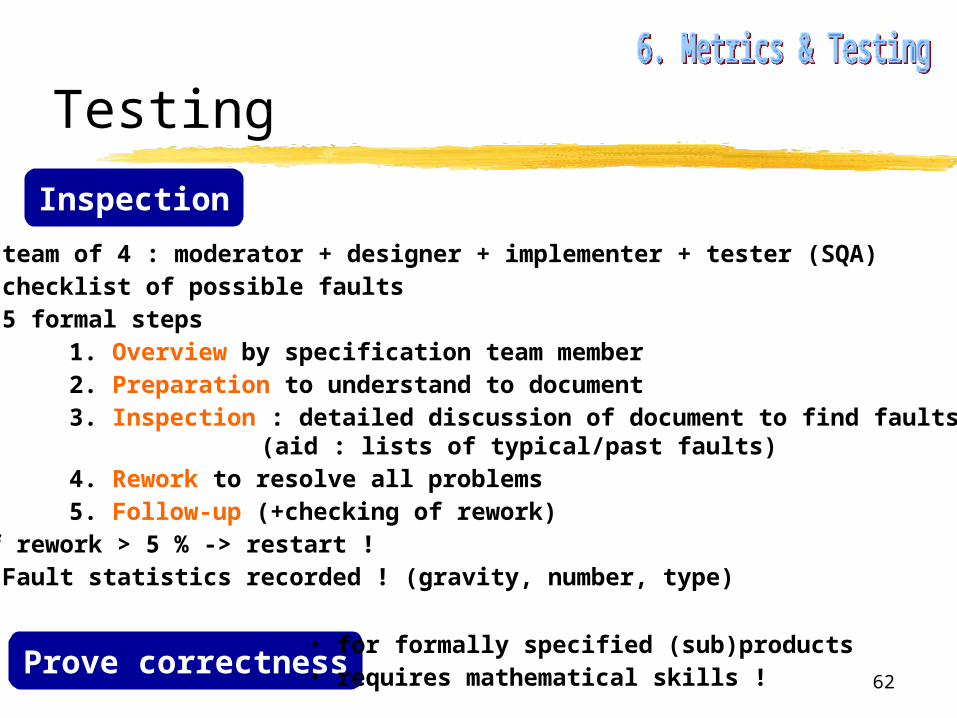
Inspection
• team of 4 : moderator + designer + implementer + tester (SQA)• checklist of possible faults • 5 formal steps
1. Overview by specification team member2. Preparation to understand to document3. Inspection : detailed discussion of document to find faults
(aid : lists of typical/past faults)4. Rework to resolve all problems5. Follow-up (+checking of rework)
if rework > 5 % -> restart !• Fault statistics recorded ! (gravity, number, type)
Prove correctness• for formally specified (sub)products• requires mathematical skills !
63
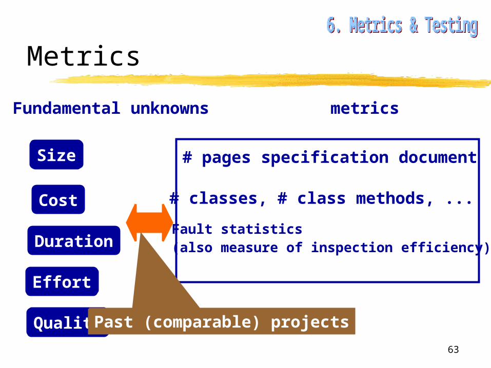
Metrics
Size
Cost
Duration
Effort
Quality
Fundamental unknowns
# pages specification document
Fault statistics(also measure of inspection efficiency)
# classes, # class methods, ...
metrics
Past (comparable) projects
64
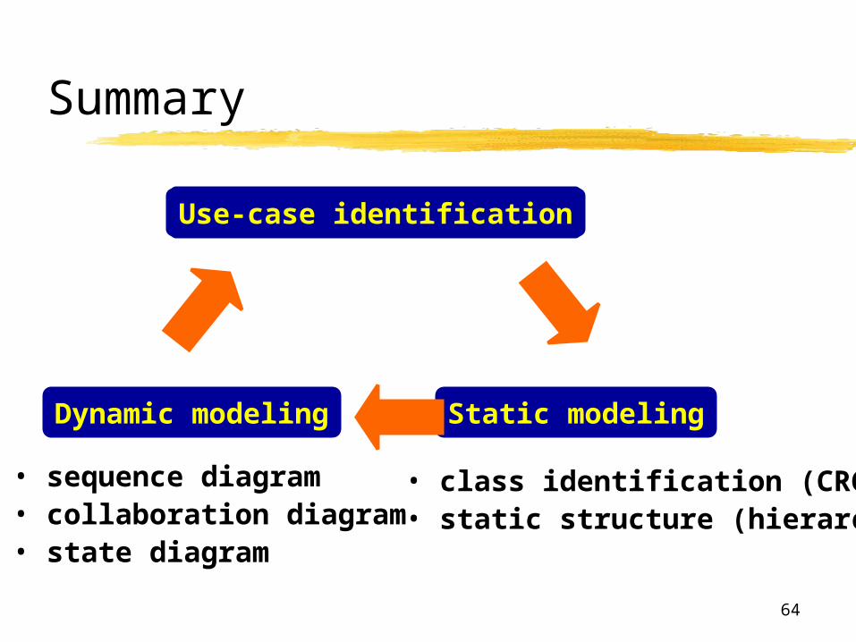
Summary
Use-case identification
Static modelingDynamic modeling
• class identification (CRC)• static structure (hierarchy)
• sequence diagram• collaboration diagram• state diagram