Single Stage High Efficiency Gas Furnaces
INSTALLATION INSTRUCTIONS
*SA UpFLOw / HORIzONTAL FURNACE *SK DOwNFLOw FURNACE
80+ AFUE
DO NOT DESTROY THIS MANUAL. KEEp IN A SAFE pLACE FOR FUTURE REFERENCE.
FIRE OR EXpLOSION HAzARD• Failuretofollowsafetywarningsexactlycould
resultinseriousinjuryorpropertydamage.• Installationandservicemustbeperformed
byaqualifiedinstaller,serviceagencyorthegassupplier.
• Do not store or use gasoline or otherflammablevaporsandliquidsinthevicinityofthisoranyotherappliance.
wHAT TO DO IF YOU SMELL GAS• Donottrytolightanyappliance.• Donot touchanyelectricalswitch;donot
useanyphoneinyourbuilding.• Leavethebuildingimmediately.• Immediately call your gas supplier from a
neighbor’sphone.Followthegassupplier’sinstructions.
• Ifyoucannotreachyourgassupplier,callthefiredepartment.
RISQUED’INCENDIEOUD’EXPLOSION•Le non-respect des avertissements de
sécurité pourrait entraîner des blessuresgraves,lamortoudesdommagesmatériels.
•L’installation et l’entretien doivent êtreeffectués par un installateur qualifié, unorganisme de service ou le fournisseur degazstaller,serviceagencyorthegassupplier.
•Nepasentreposerniutiliserdel’essencenid’autres vapeurs ou liquides inflammablesdanslevoisinagedecetappareil,nidetoutautreappareil.
QUEFAIRES’ILYAUNEODEURDEGAZ•Nepastenterd’allumeraucunappareil.•Netoucheràaucuninterrupteurélectrique;
n’utiliseraucuntéléphonedanslebâtiment.•Évacuerl’immeubleimmédiatement.•Appeler immédiatement le fournisseur de
gazenemployant le téléphoned’unvoisin.Respecter à la lettre les instructions dufournisseurdegaz.
•Sipersonnenerépond,appelerleservicedesincendies.
wARNING AVERTISSEMENT

2
IMpORTANT SAFETY INFORMATION ...................... 3
REQUIREMENTS & CODES ...................................... 3Combustion Air Quality ........................................... 4Clearances to Combustible Materials ..................... 4Heating Load .......................................................... 4Installation in a Garage ........................................... 5Operation of Furnace During Construction ............. 5
COMBUSTION AIR & VENTING REQUIREMENTS ... 6Important Information .............................................. 7Installation in a Confined Space ............................. 7Air From Inside ...................................................... 7Outdoor Air Using a Crawl Space orVented Attic ........................................................... 7Outdoor Air Using Vertical Ducts ........................... 7Outdoor Air Using Horizontal Ducts ...................... 7Air Directly Through an Exterior Wall ................... 8Alternate Method of Providing Air fromOutside .................................................................. 9
Installation in an Unconfined Space ....................... 9Category I Venting .................................................. 9Horizontal Venting ................................................ 10Flexible Vent Systems .......................................... 10
CIRCULATING AIR REQUIREMENTS ..................... 11Plenums & Air Ducts ............................................. 11Return Air Connections ......................................... 11Upflow & Horizontal Furnaces ............................ 11Downflow Furnaces ............................................ 12
Supply Air Connections ........................................ 12Acoustical Treatments .......................................... 12
FURNACE INSTALLATION ...................................... 12About the Furnace ................................................ 12Before you Install the Furnace .............................. 12Locating the Furnace ............................................ 13Upflow Furnaces ................................................... 13Horizontal Furnaces .............................................. 13Downflow Furnaces .............................................. 14Installation on a Concrete Slab ........................... 14
Pressure Switches ................................................ 15Bottom Panel Removal ......................................... 15Alternate Bottom Panel Removal ........................ 15
GAS SUppLY & pIpING ........................................... 16Leak Check .......................................................... 16High-Altitude Application ....................................... 17Conversion to LP / Propane .................................. 19
ELECTRICAL wIRING .............................................. 19Line Voltage Wiring ............................................... 19Grounding ............................................................. 20Thermostat / Low Voltage Connections ................ 21Heat Anticipator .................................................. 21
Twinning ............................................................... 21
START-UP&ADJUSTMENTS .................................. 22Pre-Start Checklist ................................................ 22Start-Up Procedures ............................................. 22Verifying & Adjusting Input Rate ........................... 22Verifying & Adjusting Temperature Rise ............... 23Verifying Burner Operation ................................... 23Verify Operation of the Supply AirLimit Switch ........................................................... 23
OpERATING SEQUENCE ........................................ 23Heating Cycle ....................................................... 23Cooling Cycle ........................................................ 23Fan Mode .............................................................. 24
MAINTENANCE ........................................................ 24
FIGURES & TABLES ................................................ 26Figure 18 - Furnace Dimensions ......................... 26
Airflow Data .......................................................... 27Table 3 - Upflow / Horizontal Gas Furnaces ........ 27Table 4 - Downflow Gas Furnaces ...................... 29
Electrical Information ............................................ 30Figure 19 - Wiring Diagram ................................. 30
Gas Information .................................................... 31Table 5 - Gas Flow Rates .................................... 31Table 6 - Gas Pipe Capacities ............................. 31Table 7 - High Altitude Deration Chart for
Propane Gas ........................................ 32Table 8 - Natural Gas Heating Values ................. 32Table 9 - High Altitude Deration Chart for
Nat. Gas - High Heating Values ............ 33Table 10 - High Altitude Deration Chart for
Nat. Gas - Low Heating Values ........... 33Troubleshooting .................................................... 34Table 11 - Control Board Fault Conditions .......... 34
Furnace Components ........................................... 34Figure 20 - Component Locations ....................... 35
INSTALLATION / pERFORMANCE CHECKLIST .... 36
TABLE OF CONTENTS
3
IMpORTANT SAFETY INFORMATIONINSTALLER: Please read all instructions before servicing this equipment. Pay attention to all safety warnings and any other special notes highlighted in the manual. Safety markings are used frequently throughout this manual to designate a degree or level of seriousness and should not be ignored.
wARNING - indicates a potentially hazardous situation that if not avoided, could result in personal injury or death.
CAUTION - indicates a potentially hazardous situation that if not avoided, may result in minor or moderate injury or property damage.
wARNING:The safety information listed in this manualmust be followed during the installation,service,andoperationofthisunit.Unqualifiedindividualsshouldnotattempttointerprettheseinstructionsorinstallthisequipment.Failuretofollowsafetyrecommendationscouldresultinpossibledamagetotheequipment,seriouspersonalinjuryordeath.
wARNING:Improper installation, service, adjustment,or maintenance may cause explosion, fire,electricalshockorotherhazardousconditionswhichmayresultinpersonalinjuryorpropertydamage. Unless otherwise noted in theseinstructions, only factory authorized kits oraccessoriesmaybeusedwiththisproduct.
wARNING:Unlessotherwisenotedintheseinstructions,onlyfactoryauthorizedkitsoraccessoriesmaybeusedwithorwhenmodifyingthisproduct.
wARNING:Donotinstallthisfurnaceifanyparthasbeensubmerged under water. A flood damagedfurnace is extremely dangerous. Attempts tousethefurnacemayresultinfireorexplosion.Aqualifiedserviceagencyshouldbecontactedtoinspectthefurnaceandtoreplaceanyelectricalorcontrolsystempartsthathavebeenwetorunderwater.
• Tominimizeequipmentfailureorpersonalinjury,itisessential that only qualified individuals install, service, or maintain this equipment. If you do not posses mechanical skills or tools, call your local dealer for assistance.
• Followall precautions in the literature, on tags, andon labels provided with the equipment. Read and thoroughly understand the instructions provided with the equipment prior to performing the installation and operational checkout of the equipment.
• Usecautionwhenhandlingthisapplianceorremovingcomponents. Personal injury can occur from sharp metal edges present in all sheet metal constructed equipment.
• Donotstoreanyofthefollowingon,orincontactwith,the unit: Rags, brooms, vacuum cleaners, or other cleaning tools, spray or aerosol cans, soap powders, bleaches, waxes, cleaning compounds, plastics or plastic containers, paper bags or other paper products, gasoline, kerosene, cigarette lighter fluid, dry cleaning fluids, paint thinners, or other volatile fluids.
• Theinstallershouldbecomefamiliarwiththeunitswiringdiagram before making any electrical connections to the unit. See the unit wiring label or Figure 19 (page 30).
• Alwaysreinstall thedoorsontheindoorblowerafterservicing or cleaning/changing the filters. Do not operate the indoor blower without all doors and covers in place.
REQUIREMENTS & CODES• This furnace must be installed in accordance with
these instructions, all applicable local building codes and the current revision of the National Fuel Gas Code (NFPA54/ANSI Z223.1) or the Natural Gas and Propane Installation Code, CAN/CGA B149.1.
• Useonlywith typeofgasapprovedfor this furnace.Refer to the furnace rating plate.
• Install this furnaceonly ina locationandpositionasspecified on page 5.
• Provideadequatecombustionandventilationairtothefurnace space as specified on pages 6 - 10.
• Combustion products must be discharged outdoors.Connect this furnace to an approved vent system only, as specified on pages 9 - 10.
• Never test for gas leaks with an open flame. Usea commercially available soap solution to check all connections. See pages 16 - 17.
• Thisfurnaceisdesignedtooperatewithamaximumexternal pressure rise of 0.5 inches of water column. Consult Tables 3 & 4 (pages 27 - 29), and the rating plate for the proper circulating air flow and temperature rise. It is important that the duct system be designed to handle the desired flow rate and temperature rise. An improperly designed duct system can result in nuisance shutdowns, and comfort or noise issues.
• Whensupplyductscarryaircirculatedbythefurnaceto areas outside the space containing the furnace, the return air shall also be handled by duct(s) sealed to the furnace casing and terminating outside the space containing the furnace. See pages 11 - 12.
• This furnace may be used for temporary heating ofbuildings or structures under construction. See the guidelines listed on page 5.

4
CombustionAirQuality
CAUTION:Combustion air must not be drawn from acorrosiveatmosphere.
To maximize heat exchanger life, the combustion air must be free of chemicals that can form corrosive acidic compounds in the combustion gases. The recommended source of combustion air is to use outdoor air. However, the use of indoor air in most applications is acceptable except as listed:
ClearancestoCombustibleMaterialsThis furnace is Design Certified in the U.S. and Canada by CSA International for the minimum clearances to combustible materials. NOTE: The furnace is listed for installation on combustible or non-combustible flooring. However, wood is the only combustible flooring allowed for installation. Downflow models must use the appropriate subase kit when installing over a wood floor. To obtain model number and specific clearance information, refer to the furnace rating plate, located inside of the furnace cabinet.
Access for positioning and servicing the unit must be considered when locating unit. The need to provide clearance for access to panels or doors may require clearance distances over and above the requirements. Allow24inchesminimumclearancefromthefrontoftheunit.However36inchesisstronglyrecommended.See Figure 1 (page 5) for minimum clearance requirements.
HeatingLoadThe furnace should be sized to provide the design heating load requirement. Heating load estimates can be made using approved methods available from Air Conditioning Contractors of America (Manual J); American Society of Heating, Refrigerating, and Air Conditioning Engineers; or other approved engineering methods. Excessiveoversizing of the furnace could cause the furnaceand/orventtofailprematurely.
The information listed below is for reference purposes only and does not necessarily have jurisdiction over local or state codes. Always consult with local authorities before installing any gas appliance.
Combustion&VentilationAir• US:NationalFuelGasCode(NFGC),AirforCombustion
and Ventilation• CANADA:NaturalGasandPropaneInstallationCodes
(NSCNGPIC), Venting Systems and Air Supply for Appliances
DuctSystems• USandCANADA:AirConditioningContractorsAssociation
(ACCA) Manual D, Sheet Metal and Air Conditioning Contractors National Association (SMACNA), or American Society of Heating, Refrigeration, and Air Conditioning Engineers (ASHRAE) Fundamentals Handbook
ElectricalConnections• US:NationalElectricalCode(NEC)ANSI/NFPA70• CANADA:CanadianElectricalCodeCSAC22.1
GasPiping&GasPipePressureTesting• US:NFGCandNationalPlumbingCodes• CANADA:NSCNGPIC
GeneralInstallation• US:CurrenteditionoftheNFGCandtheNFPA90B.For
copies, contact the National Fire Protection Association Inc., Batterymarch Park, Quincy, MA 02269; or American Gas Association, 400 N. Capitol, N.W., Washington DC 20001 or www.NFPA.org
• CANADA:NSCNGPIC.Foracopy,contactStandardSales,CSA International, 178 Rexdale Boulevard, Etobicoke (Toronto), Ontario, M9W 1R3 Canada
Safety• US: (NFGC) NFPA 54–1999/ANSI Z223.1 and the
Installation Standards, Warm Air Heating and Air Conditioning Systems ANSI/NFPA 90B.
• CANADA: CAN/CGA-B149.1 and .2–M00 NationalStandard of Canada. (NSCNGPIC)
• Agas-firedfurnaceforinstallationinaresidentialgaragemust be installed as specified on page 5.
• Thisfurnaceisnotapprovedforinstallationinmobilehomes. Installing this furnace in a mobile home could cause fire, property damage, and/or personal injury.
• If the furnace is installed in a confined space, it isrequired that the necessary combustion air come from the outdoors by way of attic, crawl space, air duct, or direct opening. For Installations in confined spaces, see pages 7 - 9 for combustion air requirements.
• Installationsintheselocationsmayrequireoutdoorairfor combustion, due to chemical exposures:
Commercial buildingsBuildings with indoor poolsFurnaces installed in laundry roomsFurnaces installed in hobby or craft roomsFurnaces installed near chemical storage areas
• Exposuretothefollowingsubstancesinthecombustionair supply may require outdoor air for combustion:
Permanent wave solutionsChlorinated waxes and cleanersChlorine based swimming pool chemicalsWater softening chemicalsDe-icing salts or chemicalsCarbon TetrachlorideHalogen type refrigerantsCleaning solvents (perchloroethylene)Printing inks, paint removers, varnishes, etc.Hydrochloric AcidCements and gluesAntistatic fabric softenersMasonry acid washing materials

5
Figure1.MinimumClearancestoCombustibleMaterials
CLEARANCES TO COMBUSTIBLE MATERIALS
Left Side ................. 0 Inches Top ...........................0 Inches
Right Side ............... 0 Inches Front ........................ †4 Inches
Vent ........................ 0 Inches Back ........................ 0 Inches
†Allow24in.minimumclearanceforservicing.Recommendedclearance is 36 in.
UPFLOW & DOWNFLOWAPPLICATIONS
HORIZONTALAPPLICATIONS
BACK
FRONT
LEF
T S
IDE
RIG
HT
SID
E
VE
NT
VE
NT
SIDE
TOP
BO
TTO
M
SIDETOP
FRONT
The ductwork should be appropriately sized to the capacity of the furnace to ensure its proper airflow rating. For installations above 2,000 ft., the furnace should have a sea level input rating large enough that it will meet the heating load after deration for altitude.
InstallationinaGarage
wARNING:Donotplacecombustiblematerialsonoragainstthefurnacecabinetorwithin6 inchesof theventpipe.Donotplacecombustiblematerials,including gasoline or any other flammablevaporsandliquids,inthevicinityofthefurnace.
This gas-fired furnace may be installed in a residential garage with the provision that the burners and igniter are located no less than 18 inches (457mm) above the floor. The furnace must be located or protected to prevent physical damage by vehicles.
OperationofFurnaceDuringConstruction
CAUTION:Failuretofollowtheseinstructionswillvoidthefactorywarrantyandmaysignificantlyreducethelifeortheperformanceofthefurnace,and/or result inotherunsafeconditions. It is theresponsibility of the installing contractor toinsuretheseprovisionsaremet.
Operating gas furnaces in construction environments can cause a variety of problems with the furnace. Proper use of commercial portable space heating equipment during construction is recommended. This gas furnace may be used during construction if it is not in violation of any applicable codes and the following criteria are met:• The installationmustmeetallapplicablecodes.The
furnace must be permanently installed according to the instructions with the furnace including electrical supply, gas supply, duct work and venting. The furnace must be controlled by a thermostat properly installed according to the instructions supplied with the furnace and thermostat. The installation must include a properly installed filter in the return air system with no by-pass air. The filter must be inspected frequently and replaced when necessary.
• Combustion air must be supplied from outside thestructure and located such that dust and gases from construction activity are not introduced into the combustion system.
• Before occupying the structure: The filter must bereplaced or cleaned, the duct work must be inspected and cleaned of any construction debris, and the furnace must be cleaned and/or repaired if found to be dirty, damaged, or malfunctioning in any way by a qualified HVAC technician. The furnace shall be inspected and approved by applicable local authority even if this requires redundant inspections.
• Serialnumbersforfurnacesusedduringconstructionmust be submitted in writing (fax and email also acceptable). This information will be used to track the long-term affects of the use during construction on furnaces. Proof of this submittal shall be available for the final inspection of the furnace prior to occupancy.
• This furnace is designed to operate with return airtemperatures in ranges normally found in occupied residences, including setbacks. Minimum continuous return temperature must not fall below 60° F (15° C). Occasionally a temporary return temperature of 55° F (12° C) is acceptable. However, operation with a return temperature below 55° F (12° C) is not allowed.

6
COMBUSTION AIR & VENTING REQUIREMENTS
RISQUED’EMPOISONNEMENTAUMONOXYDE DE CARBONED
Lenon-respectdesconsignessuivantesportantsurchacundesappareils raccordésausystèmed’évacuation mis en service pourrait entraînerl’empoisennement au monoxyde de carbone oula mort. Les consignes suivantes doivent êtreobservées pour chaque appareil raccordé ausystèmed’évacuationmisenservicesilesautresappareils raccordés au système ne sont pas enservice:
1.Scellertouteouverturenonutiliséedelasystémed’évacuation;
2.S’assurerquelasystémed’évacuationprésentedesdimensionsetunepentehorizontaleconformesàlanormeANSIZ223.1/NFPA54,intituléeNationalFuelGasCodeouauxcodesd’installationCSA-B149.1,ainsi qu’aux présentes instructions. S’assurerquelasystémed’évacuationn’estpasbloquée,restreinte,corrodée,qu’ellenefuitpasetqu’elleneprésenteaucunautredéfautpotentiellementdangereux;
3.Dans la mesure du possible, fermer toutes lesportesetfenêtresdubâtiment,ettouteslesportesentrelapièceoùsetrouvel’appareilraccordéàlasystémed’évacuationetlesautrespiècesdubâtiment.
4.Fermerlesregistresdesfoyers;5.Mettre en service les sécheuses et tout autre
appareil qui n’est pas raccordé à la systémed’évacuation.Fairefonctionneràrégimemaximaltoutventilateurd’évacuation,telqueleshottesdecuisinièreetlesventilateursdesallesdebains.Nepasmettreenservicelesventilateursd’été.
6.Respecterlesinstructionsd’allumage.Mettreenservice l’appareilà l’essai.Régler le thermostatdemanièreàceque l’appareil fonctionnesansinterruption;
7.Vérifiers’ilyadébordementàl’orificed’évacuationducoupetiragedesappareilsdotésd’uncoupetirage 5 minutes après l’allumage du brûleurprincipal. Utiliser la flamme d’une allumette oud’unechandelle.
8.Sil’onconstate,aucoursdel’undesessaisquiprécèdent,quel’évacuationestdéficiente,corrigerlesystèmed’évacuationconformémentàlanormANSIZ223.1/NFPA54,NationalFuelGasCode,et(ou)auxcodesd’installationCSAB149.1.
9.Après avoir déterminé que tous les appareilsraccordés à la systéme d’évacuation évacuentcorrectementtelqueprescritci-dessus,rouvrirlesportesetlesfenêtresetremettrelesventilateursd’évacuation, les registres de foyers et toutautreappareilfonctionnantaugazàleurétatdefonctionnementinitial.
CARBON MONOXIDE pOISONING HAzARDFailure to follow the steps outlined belowforeachapplianceconnectedtotheventingsystem being placed into operation couldresultincarbonmonoxidepoisoningordeath.
The following steps shall be followed witheachindividualapplianceconnectedtotheventing system being placed in operation,whileallotherappliancesconnectedtotheventingsystemarenotinoperation:
1.Sealanyunusedopeningsintheventingsystem.2.Inspecttheventingsystemforpropersizeand
horizontalpitch,asrequiredintheNationalFuelGasCode,ANSIZ223.1/NFPA54ortheCSAB149.1,NaturalGasandPropaneInstallationCodesandthese instructions. Determine that there is noblockageorrestriction, leakage,corrosionandotherdeficiencieswhichcouldcauseanunsafecondition.
3.Asfaraspractical,closeallbuildingdoorsandwindowsandalldoorsbetweenthespaceinwhichtheappliance(s)connectedtotheventingsystemarelocatedandotherspacesofthebuilding.
4.Closefireplacedampers.5.Turn on clothes dryers and any appliance not
connected to the venting system.Turn on anyexhaustfans,suchasrangehoodsandbathroomexhausts, so they are operating at maximumspeed.Donotoperateasummerexhaustfan.
6.Follow the lighting instructions. Place theappliance being inspected into operation.Adjustthethermostatsoapplianceisoperatingcontinuously.
7.Test for spillage from draft hood equippedappliancesatthedrafthoodreliefopeningafter5minutesofmainburneroperation.Usetheflameofamatchorcandle.
8.Ifimproperventingisobservedduringanyoftheabovetests,theventingsystemmustbecorrectedinaccordancewiththeNationalFuelGasCode,ANSIZ223.1/NFPA54and/orCSAB149.1,NaturalGasandPropaneInstallationCodes.
9.Afterithasbeendeterminedthateachapplianceconnectedtotheventingsystemproperlyventswhen tested as outlined above, return doors,windows, exhaust fans, fireplace dampers andany other gas-fired burning appliance to theirpreviousconditionsofuse.
wARNING: AVERTISSEMENT:

7
ImportantInformation• Provisions must be made during the installation
of this furnace that provide an adequate supplyof air for combustion.Furnace installationusingmethodsotherthanthosedescribedinthefollowingsectionsmustcomplywiththeNationalFuelGasCode(NFGC)andallapplicablelocalcodes.
• Instructions for determining the adequacy ofcombustionairforaninstallationcanbefoundinthecurrentrevisionoftheNFGC(ANSIZ223.1/NFPA54).Consultlocalcodesforspecialrequirements.TheserequirementsareforUSinstallationsasfoundinthe NFGC.
• TherequirementsinCanada(B149.1)arestructureddifferently. Consult with B149.1 and local codeofficialsforCanadianinstallations.
CAUTION:Exhaust fans, clothes dryers, fireplaces andotherappliancesthatforceairfromthehousetotheoutdoorscancreateanegativepressureinsidethehouse,resultinginimproperfurnaceoperationorunsafeconditionssuchasflamerollout.Itisimperativethatsufficientairexchangewith the outdoors is provided to preventdepressurization.AdditionalinformationabouthowtotestfornegativepressureproblemscanbefoundintheNFGC.
Air openings on top of the furnace and openings in closet doors or walls must never be restricted. If the furnace is operated without adequate air for combustion, the flame roll-out switch will open, turning off the gas supply to the burners. NOTE:Thissafetydeviceisamanuallyresetswitch. DO NOT install jumper wires across theseswitches todefeat their functionor reset aswitchwithoutidentifyingandcorrectingthefaultcondition.If a switch must be replaced, use only the correct sized part specified in the Replacement Parts List provided online.
InstallationInAConfinedSpaceA confined space is an area with volume less than 50 cubic feet per 1,000 Btuh of the combined input rates of all appliances drawing combustion air from that space. Furnace closets, small equipment rooms and garages are confined spaces. Furnaces installed in a confined space which supply heated air to areas outside the space must draw return air from outside the space and must have the return air ducts tightly sealed to the furnace.
The required sizing of these openings is determined by whether inside or outside air is used to support combustion, the method by which the air is brought to the space, and by the total input rate of all appliances in the space. In all cases, the minimum dimension of any combustion air opening is 3 inches.
Air From InsideIf combustion air is taken from the heated space, the two openings must each have a free area of at least 1 in2 per 1,000 Btuh of total input of all appliances in the confined space, but notlessthan100 in2 of free area. See Figure 2 and the example below.
Example:If the combined input rate of all appliances is less than or equal to 100,000 Btuh, each opening must have a free area of at least 100 in2. If the combined input rate of all appliances is 120,000 Btuh, each opening must have a free area of at least 120 in2.
Outdoor Air from a Crawl Space or Vented AtticWhen the openings can freely exchange air with the outdoors, each opening shall have a minimum free area of 1 in2 per 4,000 Btuh of total appliance input. The openings shall exchange directly, or by ducts, with the outdoor spaces (crawl or attic) that freely exchange with the outdoors (Figure 3, page 8).
Outdoor Air Using Vertical DuctsIf combustion air is taken from outdoors through vertical ducts, the openings and ducts must have a minimum free area of 1in2 per 4,000 Btuh of total appliance input. In installations drawing combustion air from a ventilated attic, both air ducts must extend above the attic insulation. See Figure 4 (page 8).
Outdoor Air Using Horizontal DuctsIf combustion air is taken from outdoors through horizontal ducts, the openings and ducts must have a minimum free area of 1in2 per 2,000 Btuh of total appliance input. See Figure 5 (page 8).
Furnace
12" Max.
WaterHeater
Vent or Chimney
NOTES: Each opening must be at least 100 sq. in.or 1 sq. in. per 1,000 Btuh of total input rating, whichever is greater.
Openings must start atno more than 12 inchesfrom the top and bottomof the enclosure.
12” Max.
See Notes
See Notes
Figure2.CombustionAirDrawnfromInside
TotalInputRating(Btuh)
MinimumFreeArea(EachOpening)
RoundDuctDiameter
40,000 100 in2 12 inches60,000 100 in2 12 inches80,000 100 in2 12 inches
100,000 100 in2 12 inches120,000 120 in2 13 inches140,000 140 in2 14 inches160,000 160 in2 15 inches

8
Figure5.CombustionAirDrawnfromOutsideThroughHorizontalDucts
---------
---------
12" Max
12" Max
Furnace
Vent or Chimney
Water Heater
---------
---------
---------
---------
Air Duct
Air Duct
NOTE: Each opening to outside must be at least 1 sq. in. per 2,000 Btuh of total input rating.
SeeNote
TotalInputRating(Btuh)
MinimumFreeArea(EachOpening)
RoundDuctDiameter
40,000 10 in2 5 inches60,000 15 sin2 6 inches80,000 20 in2 7 inches
100,000 25 in2 8 inches120,000 30 in2 9 inches140,000 35 in2 10 inches160,000 40 in2 10 inches
Figure6.CombustionAirDrawnfromOutsideThroughanExteriorWall
---------
---------
12" Max
12" Max
FurnaceNOTE: Each opening to outside must be at least 1 sq. in. per 4,000 Btuh of total input rating.
Vent or Chimney
Water Heater
See Note
TotalInputRating(Btuh)
MinimumFreeArea(EachOpening)
RoundDuctDiameter
40,000 10 in2 4 inches60,000 15 in2 5 inches80,000 20 in2 5 inches100,000 25 in2 6 inches120,000 30 in2 6 inches140,000 35 in2 7 inches160,000 40 in2 8 inches
Figure4.CombustionAirDrawnfromOutsideThroughVerticalDucts
Inlet Air Duct mustbe at least 1 sq. in.per 4,000 Btuh oftotal input rating.
Inlet and Outlet Ducts must extend aboveattic insulation.
Outlet Air Duct mustbe at least 1 sq. in.per 4,000 Btuh oftotal input rating.
Ventilation Louvers ateach end of attic
AtticInsulation
12" Max
FurnaceWater Heater
Vent orChimney
TotalInputRating(Btuh)
MinimumFreeArea(EachOpening)
RoundDuctDiameter
40,000 100 in2 12 inches60,000 100 in2 12 inches80,000 100 in2 12 inches
100,000 100 in2 12 inches120,000 120 in2 13 inches140,000 140 in2 14 inches160,000 160 in2 15 inches
Figure3.CombustionAirDrawnfromaCrawlSpaceorVentedAttic
AtticInsulation
Crawl SpaceVentilated Louvers for unheated crawl space
Inlet air duct must be at least 1 sq. in. per 4,000 Btuh of total input rating.
Outlet air duct must be at least 1 sq. in. per 4,000 Btuh of total input rating. Must extend above attic insulationWater
Heater Furnace
Vent orChimney
Ventilation louversat each end of attic
Air Directly Through An Exterior WallIf combustion air is provided directly through an exterior wall, the two openings must each have free area of at least 1in2 per 4,000 Btuh of total appliance input. See Figure 6.

9
CategoryIVentingThis furnace is listed as a Category I vented appliance. Category I furnaces generally operate with a slight negative pressure (draft) and must be vented vertically or near vertical. Additionally it is important to guard against excessive condensation.
wARNING:Upon completion of the furnace installation,carefully inspect theentirefluesystembothinsideandoutsidethefurnacetoassureitisproperlysealed.Leaksinthefluesystemcanresultinseriouspersonalinjuryordeathduetoexposureofflueproducts,includingcarbonmonoxide.
wARNING:Venting intoanunlinedmasonrychimneyorconcretechimneyisprohibited.Thismayresultin improper draft and excess condensationforminginthechimney.
• This furnacemustbevented incompliancewiththecurrentrevisionoftheNationalFuelGasCode (ANSI-Z223.1/NFPA54)andtheinstructionsprovidedbelow.Consultlocalcodesforspecialrequirements.
• InCanada,ventingshallconformtotherequirementsofthecurrent(CAN/CGAB149.1or.2)installationcodes.Consultlocalcodesforspecialrequirements.
• CategoryIfurnaceinstallationsmustbeconnectedtoafactorybuiltchimneyorventcomplyingwitharecognizedstandard,oramasonryorconcretechimneylinedwithaliningmaterialacceptabletotheauthorityhavingjurisdiction.
• IntheU.S.,thisfurnacemustneverbeventedtoachimneyorfluethatservicesafireplaceorotherappliancedesignedtoburnsolidfuel.Ifthefurnacevent is to be connected to a chimney serving afireplace,thefireplacemustbesealedofffromthechimney.InCanada,commonventingwithafireplaceispermitted.ConsultB149.1andyourlocalcodeauthority.
• Thisfurnacemaybeventedwithadedicatedventingsystem or common vented with other Category I appliances. The vent system dimensions and material must conform to the NFGC or local Codes. Generally, this means using Type B vent pipe or a lined masonry chimney. When consulting the vent sizing tables in the NFGC, the MAX capacity of the vent must be greater than the furnaces high fire rate. The MIN capacity must be lower than the low fire rate. If the venting system is inappropriate for the furnace, the venting system will need to be modified to comply with NFGC or local
InstallationInAnUnconfinedSpaceAn unconfined space is an area including all rooms not separated by doors with a volume greater than 50 cubic feet per 1,000 Btuh of the combined input rates of all appliances which draw combustion air from that space.
In general, a furnace installed in an unconfined space will not require outside air for combustion. However, in homes built for energy efficiency (low air change rates), it may be necessary to provide outside air to ensure adequate combustion and venting, even though the furnace is located in an unconfined space. See example.
Example:A space with a water heater rated at 45,000 Btuh input and a furnace rated at 75,000 Btuh requires a volume of 6,000 cubic feet [50 x (45 + 75) = 6,000] to be considered unconfined. If the space has an 8 foot ceiling, the floor area of the space must be 750 sq. ft. (6,000 / 8 = 750).
Alternate Method of Providing Air from Outside:If acceptable under local Codes, it is permitted to provide outside air using one opening (See NFGC). Generally, confined spaces must have 2 openings in the space for combustion air. One opening must be within 12 inches of the ceiling, and the other must be within 12 inches of the floor. However, an alternative method recently adopted by the NFGC uses one opening within 12 inches of the top of the space. This method may be used if it is acceptable to the local codes.
Thefollowingconditionsmustbemet:
1. The opening must start within 12” of the top of the structure and connect with the out of doors through vertical or horizontal ducts or be ducted to a crawl or attic space that connects with the out of doors.
2. The opening must have a minimum free area of 1 in2. per 3,000 Btu per hour of the total input rating of all equipment located in the enclosure.
3. The free area must not be less than the sum of all the areas of the vent connectors in the enclosure.

10
codes. Theminimumdiameterofanyventpipeis4inches.
• Theventingsystemshouldbedesigned tohave theminimum number of elbows or turns. All horizontal runs shall slope upwards from the furnace at ¼ inch per running foot of vent. Supports for the vent pipe must be installed a minimum of every five feet along the vent run to ensure no displacement after installation. Under no circumstances shall any portion of the vent system extend into or pass through any return air duct, supply air duct, or plenum.
• Singlewall vent connectorsmaybeusedunder thelimited capacity ranges found in the vent sizing tables. It is recommended that Type B double wall vent be used for the connector whenever possible. An existing masonry chimney should be inspected and relined if necessary.
• SinglewallmetalverticalventsshallnotbeusedforCategory I venting. The furnace vent, if metal, may be insulated if local codes allow. Any part of the vent system, metal vent only, not exposed to weather, but which are exposed to temperatures below 35° F (1° C) must be insulated to prevent condensation. All vent insulation shall be foil backed fiberglass of one inch minimum thickness.
• Sheetmetalfastenersshouldbeusedtosecuretheventpipe to the furnace flue. However, the NFGC states that alternative vent products may be attached according to the vent manufacturers instructions.
• When an existing furnace is removed from a ventsystem serving other appliances, the existing vent system may no longer be sized to properly vent the remaining appliances. An improperly sized venting system can result in the formation of condensate, leakage, or spillage. The existing vent system should also be checked to make sure it remains in compliance with NFGC. If it isn’t, the vent system must be brought into compliance before installing the furnace.
HorizontalVenting• Horizontalventsystemsmustbesealedwithahigh
temperature sealant that can withstand temperatures of 450° F. Recommended sealants: Dow Corning Sealant 736 RTV; GE 106 RTV; High Tech Ind., High TEMP RED.
• This furnace is not approved for horizontal venting without the use of an add-on power venter. Power venters establish negative pressure in the vent piping and the furnace operates as if connected to a Category I vertical vent. The power venter is only for use when exhausting through an exterior wall.
• The power venter must be installed according to the instructions provided by the power venter manufacturer and applicable requirements of local codes. For Canadian installations please refer to the Canadian Installation Code (CAN/CGA-B149.1 or 2) and/or local codes.
• The outlet of the vent must be at least 12 inches above the highest expected snow accumulation.
FlexibleVentSystemsFlexible venting systems are approved for use providing they are listed for the application and meet all local Code requirements. These systems are primarily used to line existing masonry chimneys. They must be sized to the application according to the sizing tables in the National Fuel Gas Code, including the required 20% reduction in maximum capacity.
Flexible venting systems are permitted to be used as the vent connector. However, great care must be taken to ensure that there are no sags in the venting system which could accumulate condensate. The flexible vent system must be supported at no more than 5 foot intervals and maintain a minimum slope of ¼ inch per foot of horizontal run.
11
wARNING:Donotallowcombustionproductstoenterthecirculating air supply. Failure to prevent thecirculation of combustion products into thelivingspacecancreatepotentiallyhazardousconditions including carbon monoxidepoisoningthatcouldresultinpersonalinjuryordeath.
All return ductwork must be secured tothe furnace with sheet metal screws. Forinstallations in confined spaces, all returnductwork must be adequately sealed. Whenreturnairisprovidedthroughthebottomofthefurnace,thejointbetweenthefurnaceandthereturnairplenummustbeairtight.
Thesurfacethatthefurnaceismountedonmustprovidesoundphysicalsupportofthefurnacewithnogaps,cracksorsaggingbetweenthefurnaceandthefloororplatform.
Returnairandcirculatingairductworkmustnotbeconnectedtoanyotherheatproducingdevicesuchasafireplaceinsert,stove,etc.Thismayresultinfire,explosion,carbonmonoxidepoisoning,personalinjury,orpropertydamage.
Plenums&AirDucts• Plenumsandairductsmustbeinstalledinaccordance
with the Standard for the Installation of Air Conditioning and Ventilating Systems (NFPA No. 90A) or the Standard for the Installation of Warm Air Heating and Air Conditioning Systems (NFPA No. 90B).
• Tables4&5 (pages27 -29)contain themaximumairflow and temperature rise data for each furnace input rate. If the maximum airflow is 1,600 CFM or more, it is recommended that two openings be used for return air on upflow furnaces. Downflow furnaces can only use one return opening.
• It is recommended that the outlet duct contain aremovable access panel. The opening should be accessible when the furnace is installed in service and shall be of a size that smoke or reflected light may be observed inside the casing to indicate the presence of leaks in the heat exchanger. The cover for the opening shall be attached in such a manner as to prevent leaks.
• Ifoutsideair isusedas returnair to the furnace forventilation or to improve indoor air quality, the system must be designed so that the return air is not less than 60° F (15° C) during operation. If a combination of indoor
and outdoor air is used, the ducts and damper system must be designed so that the return air supply to the furnace is equal to the return air supply under normal, indoor return air applications.
• When a cooling system is installed which uses thefurnace blower to provide airflow over the indoor coil, the coil must be installed downstream (on the outlet side) of the furnace or in parallel with the furnace.
• If a cooling system is installed in parallel with thefurnace, a damper must be installed to prevent chilled air from entering the furnace and condensing on the heat exchanger. If a manually operated damper is installed, it must be designed so that operation of the furnace is prevented when the damper is in the cooling position and operation of the cooling system is prevented when the damper is in the heating position.
• Seal all connections and joints with industrial gradesealing tape or liquid sealant. Requirements for sealing ductwork vary from region to region. Consult with local codes for requirements specific to your area.
ReturnAirConnections• In applications where the supply ducts carry heated
air to areas outside the space where the furnace is installed, the return air must be delivered to the furnace by duct(s) secured to the furnace casing, running full size and without interruption. Donotusethebackofthefurnaceforreturnair.
• Positionthefurnacewiththereturnairductworkensuringeven alignment of furnace (or coil casing) air opening and return air duct. NOTE: The ductwork must have an opening equal to that of the return air opening of the furnace (or coil casing). See Figure 18 (page 26) for return air opening size.
Upflow & Horizontal Furnaces• The return air ductwork may be connected to the left
side, right side, or bottom of the furnace. NOTE: If using the left or right side of the furnace for return air, the bottom panel (Figure 18) must not be removed from the bottom of the furnace.
wARNING:The bottom panel of the furnace must be inplacewhenthefurnaceisinstalledwithsidereturnairducts.Removalofallorpartofthebasecouldcausecirculationof combustibleproducts into the living space and createpotentially hazardous conditions, includingcarbonmonoxidepoisoningthatcouldresultinpersonalinjuryordeath.
• SideReturnInstallations: To attach the return air duct to the left or right side of the furnace, punch out the 4 knockouts from the side of the furnace (Figure 18).
CIRCULATING AIR REQUIREMENTS

12
Using sharp metal cutters, cut an opening between all 4 knockouts to expose the blower assembly. Position the return air duct over the opening and secure to the side with sheet metal screws.
• BottomReturnInstallations: If using the bottom of the furnace for return air, the bottom panel (Figure 18) must be removed from the bottom of the furnace. See page 15 for removal instructions. Position the furnace over the return air duct and secure together with sheet metal screws. Make sure the screws penetrate the duct and furnace casing.
Downflow Furnaces• Toattachthereturnairducttothedownflowfurnace,
bend the flanges on the furnace upward 90° with wide duct pliers. See Figure 18 (page 26) for furnace flange locations. NOTE: If system installation includes AC coil casing, bend the flanges on the coil casing upward 90° before attaching the return air duct.
• Secure thereturnairductwork to the furnaceorcoilcasing (if installed) with sheet metal screws. Make sure the screws penetrate the sheet metal casing and flanges.
SupplyAirConnections• The supply air must be delivered to the heated space
by duct(s) secured to the furnace or coil box casing, running full size and without interruption.
• To attach the supply air duct to upflow & horizontal furnaces, bend the flanges on the furnace upward 90° with wide duct pliers. See Figure 18 (page 26) for furnace flange locations. NOTE: If system installation includes AC coil casing, bend the flanges on the coil casing upward 90° before attaching the supply air duct.
• Position the supply air ductwork onto the furnace ensuring even alignment of furnace air opening and supply air duct. NOTE: The ductwork must have an opening equal to that of the supply air opening of the furnace. See Figure 18 for supply air opening size.
AcousticalTreatmentsDamping ducts, flexible vibration isolators, or pleated media-style filters on the return air inlet of the furnace may be used to reduce the transmission of equipment noise eminating from the furnace. These treatments can produce a quieter installation, particularly in the heated space. However, they can increase the pressure drop in the duct system. Care must be taken to maintain the proper maximum pressure rise across the furnace, temperature rise and flow rate. This may mean increasing the duct size and/or reducing the blower speed. These treatments must be constructed and installed in accordance with NFPA and SMACNA construction standards. Consult with local codes for special requirements. For best sound performance, be sure to install all the needed gaskets and grommets around penetrations into the furnace, such as for electrical wiring.
FURNACE INSTALLATIONThese Installation procedures are suggested for typical furnace installations. Since each installation is different, the sequence of instructions may differ from the actual installation. OnlyqualifiedHVACtechniciansshouldinstall this furnace.
The installer must be familiar with and comply with all codes and regulations applicable to the installation of these heating appliances and related equipment. In the absence of local codes, the installation must be in accordance with the current provisions of one or more of the following standards.
• AmericanNationalStandard(ANSI-Z223.1/NFPA-54)and/or CAN/CSA B149 for all gas-fired furnace models.
• AmericanNationalStandard(ANSI-C1/NFPA-70)and/orCSA 22.1 Canadian Electric Code Part 1 for all electrical field wiring.
AboutTheFurnaceThe *SA / *SK series furnace is designed only for indoor installations and can be readily connected to the high static duct system of a home. *SA series gas furnaces are shipped ready for installation in the upflow or horizontal right or left positions. *SK series gas furnace may only be used for downflow operation. Units are approved for single / multistory residential structures in freestanding /closet / alcove configurations.
This appliance will provide many years of safe and dependable comfort, providing it is properly installed and maintained. Abuse, improper use, and/or improper maintenance can shorten the life of the appliance and create unsafe hazards. Please read all instructions before installing the unit.
Approved installation, operation, and maintenance of this appliance must be in accordance with the listed specifications contained in these instructions and other documents supplied with the furnace and/or optional air conditioning equipment. Unless it is noted differently in this manual, only use factory authorized kits and accessories on this appliance. Refer to local authorities having jurisdiction for further information.
BeforeYouInstalltheFurnace√ This equipment is securely packaged at the time of
shipment and upon arrival should be carefully inspected for damage prior to installing the equipment at the job site. Claims for damage (apparent or concealed) should be filed immediately with the carrier.
√ Check the electrical supply and verify the power supply is adequate for unit operation. The system must be wired and provided with circuit protection in accordance with local building codes. If there is any question concerning the power supply, contact the local power company.
√ Verify the air delivery of the furnace is adequate to handle the static pressure drop of the coil, filter, and duct work.

13
LocatingtheFurnace• Thedimensionsoftheroomoralcovemustbeableto
accommodate the overall size of the furnace and required clearances to combustible materials listed in Figure 1 (page 5). Access for positioning and servicing must also be considered when locating the unit. To determine the required clearances needed for installation, refer to Figure 18 (page 26) for overall dimensions.
• Thefurnacemustbeinstalledonasolidsurfaceandmustbe level front-to-back and side-to-side at installation. The surface that the furnace is mounted on must provide sound physical support of the unit. Secure the furnace to the floor.
• Thefurnaceshouldbeinstalledasclosetothecenterofthe air distribution system as possible and attached to a properly installed duct system. Donotusethebackofthefurnaceforreturnair.See pages 11 - 12 for circulating requirements.
• The furnace must be installed so that all electricalcomponents are protected from water.
• TheplenumattachedtotheA/Ccoilboxandductworkwithin 3 ft. of the furnace must be installed so that surfaces are at least 1” from combustible construction.
• Wheninstalledinaresidentialgarage,thefurnacemustbe positioned so the burners and the source of the ignition are located no less than 18 inches above the floor and protected from physical damage by vehicles.
• The furnace must be installed upstream from arefrigeration system.
• The furnace requires special venting materials andinstallation procedures. See pages 9 & 10 for venting guidelines and specifications.
UpflowFurnaces
wARNING:Thefurnacemustnotbeinstalleddirectlyoncarpeting,tile,oranycombustiblematerialotherthanwoodflooring.Failuretocomplymayresultinfire,propertydamageorpersonalinjury.
*SA series gas furnaces are shipped with the bottom panel installed as shown in Figure 18 (page 26). If the furnace is installed with side return air, the bottom panel must not be removed. If the furnace is installed with bottom return air, the bottom panel must be removed. See Bottom Panel Removal on page 15.
HorizontalFurnaces
wARNING:Thefurnacemustnotbeinstalleddirectlyoncarpeting,tile,oranycombustiblematerialotherthanwoodflooring.
• The*SAseriesgasfurnacecanbeinstalledhorizontally(Figure 7) in an attic, basement, crawl space or alcove. It can also be suspended from a ceiling in a basement or utility room in either a right to left airflow or left to right airflow as shown in Figure 8.
• *SAseriesfurnacesareshippedwiththebottompanelinstalled. If the furnace is installed horizontally, remove the bottom panel from the furnace before attaching the duct system. See Bottom Panel Removal on page 15.
• Ifinstallingthefurnaceinanattic,itisrequiredthatadrip pan be placed under the furnace. If the installation is on a combustible platform (Figure 7), it is recommended that the drip pan extend at least 12 inches past the top and front of the furnace.
• Ifsuspendingthefurnacefromtheceiling,assembleasupport frame (Figure 8) using slotted iron channel and full threaded rod. Fasten the frame together with nuts, washers, and lockwashers. Secure the support frame to the rafters with lag bolts. The furnace can also be suspended using steel straps around each end of the furnace. The straps should be attached to the furnace with sheet metal screws and to the rafters with bolts.
• Itisrecommendedforfurtherreductionoffirehazardthat cement board or sheet metal be placed between the furnace and the combustible floor and extend 12 inches beyond the front of the door and top of the furnace.
Figure7.*SAHorizontalInstalledonaPlatform
Gas Inlet
Wood or non-combustible
Platform
Type “B” Vent
Coil Plenum
Electrical SupplyConnection

14
Figure8.*SAHorizontallySuspendedinAttic
Threaded Rod
LagBolt
Nuts (x2)
Washer and
Lockwasher
Nuts (x2)
Concrete Floor
Furnace
Sheet Metal
Plenum
Figure9.FurnaceonaConcreteSlab
*SKModels Dim.“A” Dim.“B”
054-23A 13 1/4 19 1/4072-24B 16 5/8 19 1/4090-24B 16 5/8 19 1/4108-35C 20 1/8 19 1/4126-45D 23 5/8 19 1/4
NOTE: Dimensions shown in Inches.
Table1.CutoutDimensions
“A”
“B”
Opening in concrete floor
DownflowInstallationThefurnacemustnotbeinstalleddirectlyoncarpeting,tile, or any combustible material other than woodflooring. To install the furnace on combustible flooring, a special sub-base is required.
wARNING:Failuretoinstallthedownflowsub-basekitmayresultinfire,propertydamageorpersonalinjury.
wARNING:Thedownflowsub-basekitmustnotbeinstalleddirectlyoncarpeting,tile,oranycombustiblematerial other than wood flooring. Failure tocomplymayresultinfire,propertydamageorpersonalinjury.
Downflow sub-base kits are factory supplied accessories and are listed according to the cabinet letter of the furnace. For ‘A’ size cabinets use Sub-Base kit #902974 only. For ‘B’, ‘C’, and ‘D’ size cabinets use Kit #904911. please followtheinstructionsprovidedwiththekit.
A downflow sub-base kit is not necessary if the furnace is installed on a factory or site-built cased air conditioning coil. However, the plenum attached to the coil casing must be installed so that its surfaces are at least 1” from combustible construction.
Installation on a Concrete Slab1. Create an opening in the floor according to the
dimensions in Table 1.2. Position the plenum and the furnace as shown in
Figure 9.
15
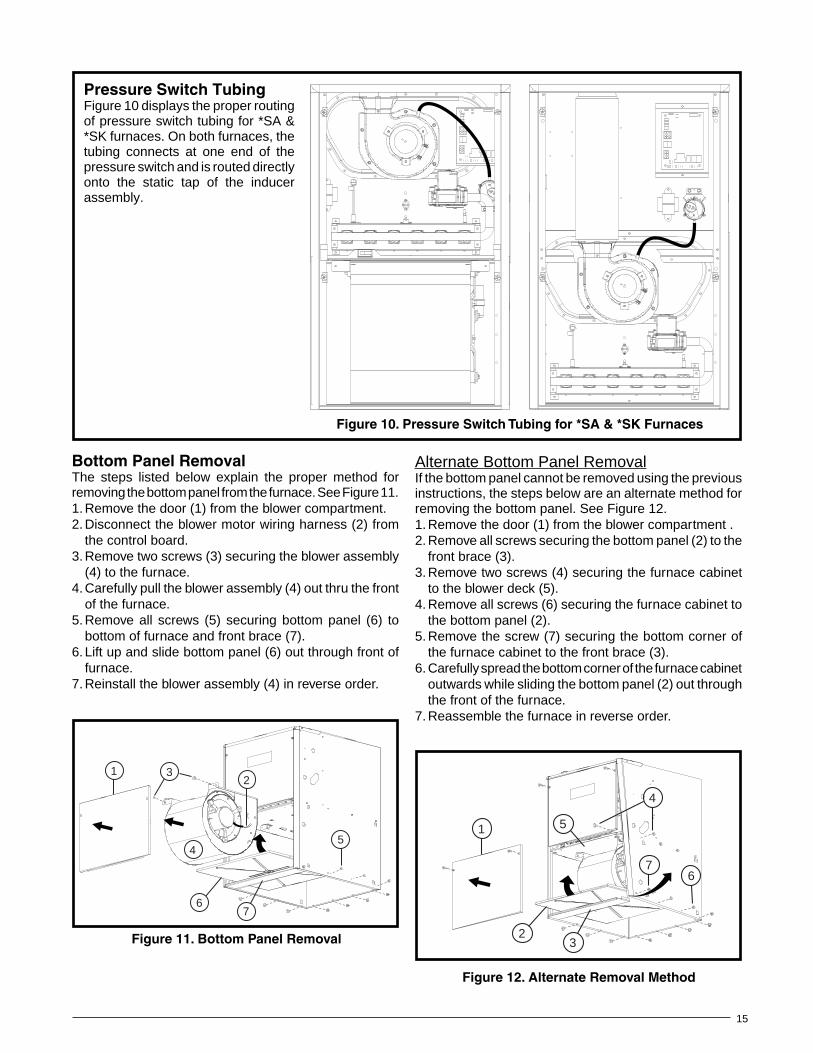
Figure12.AlternateRemovalMethod
1
4
2
7
3
6
5
Alternate Bottom Panel RemovalIf the bottom panel cannot be removed using the previous instructions, the steps below are an alternate method for removing the bottom panel. See Figure 12.1. Remove the door (1) from the blower compartment .2. Remove all screws securing the bottom panel (2) to the
front brace (3).3. Remove two screws (4) securing the furnace cabinet
to the blower deck (5).4. Remove all screws (6) securing the furnace cabinet to
the bottom panel (2).5. Remove the screw (7) securing the bottom corner of
the furnace cabinet to the front brace (3).6. Carefully spread the bottom corner of the furnace cabinet
outwards while sliding the bottom panel (2) out through the front of the furnace.
7. Reassemble the furnace in reverse order.
BottomPanelRemovalThe steps listed below explain the proper method for removing the bottom panel from the furnace. See Figure 11.1. Remove the door (1) from the blower compartment.2. Disconnect the blower motor wiring harness (2) from
the control board.3. Remove two screws (3) securing the blower assembly
(4) to the furnace.4. Carefully pull the blower assembly (4) out thru the front
of the furnace.5. Remove all screws (5) securing bottom panel (6) to
bottom of furnace and front brace (7).6. Lift up and slide bottom panel (6) out through front of
furnace.7. Reinstall the blower assembly (4) in reverse order.
67
5
12
3
4
Figure11.BottomPanelRemoval
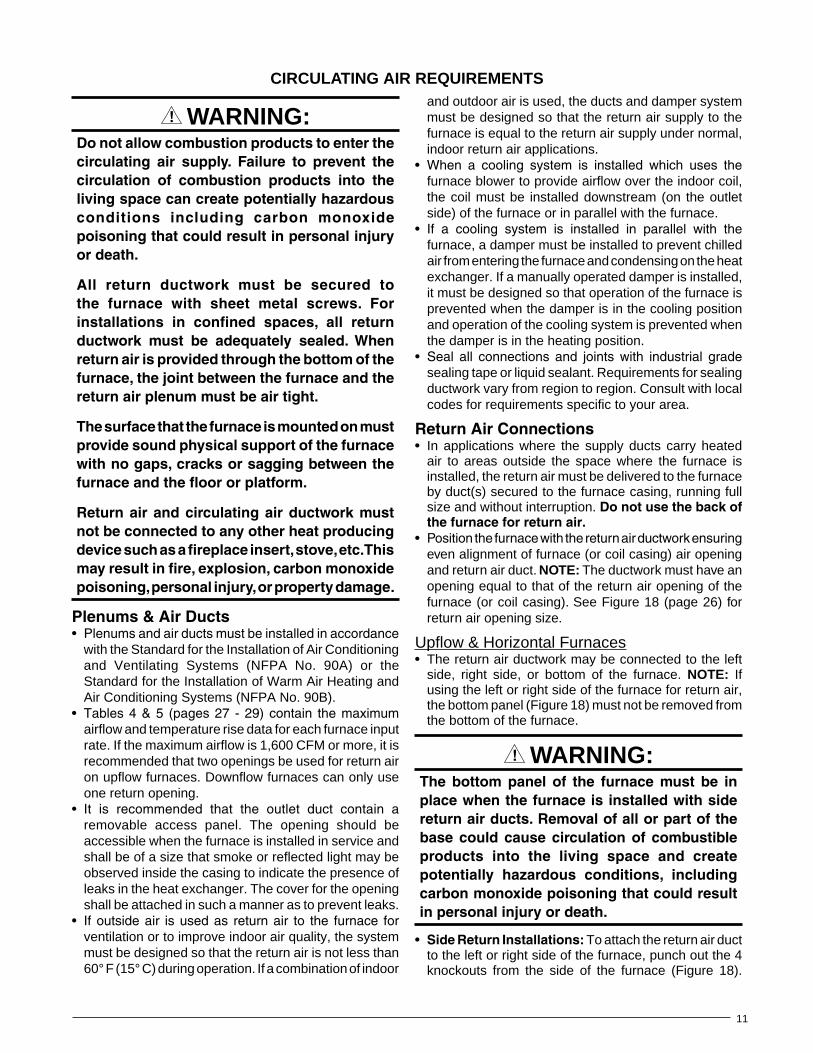
PressureSwitchTubingFigure 10 displays the proper routing of pressure switch tubing for *SA & *SK furnaces. On both furnaces, the tubing connects at one end of the pressure switch and is routed directly onto the static tap of the inducer assembly.
Figure10.PressureSwitchTubingfor*SA&*SKFurnaces

16
• Allgaspipingmustbeinstalledincompliancewithlocalcodesandutilityregulations.IntheabsenceoflocalcodesthegaslineinstallationmustcomplywiththelatesteditionoftheNationalFuelGasCode(ANSIZ223.1)or(CAN/CGAB149.1or.2)InstallationCodes.
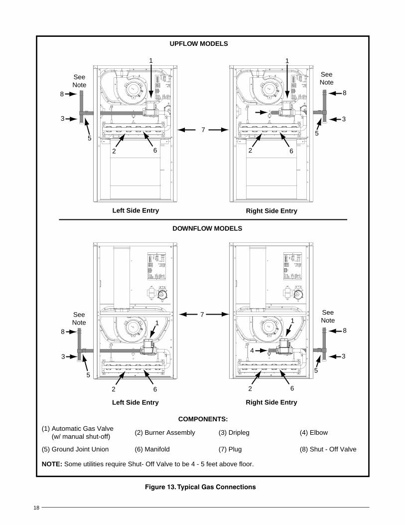
• Some local regulations require the installationofamanualmainshut-offvalveandgroundjointunionexternaltothefurnaceasshowninFigure13 (page 18). The shut-off valve should be readilyaccessible for service and/or emergency use.Consultthelocalutilityorgassupplierforadditionalrequirementsregardingplacementofthemanualmaingasshut-off.
• Gaspipingmustneverruninorthroughairducts,chimneys,gasvents,orelevatorshafts.
• CompoundsusedonthreadedjointsofgaspipingmustberesistanttotheactionsofLPpropanegas.
• Themaingasvalveandmainpowerdisconnecttothefurnacemustbeproperlylabeledbytheinstallerincaseemergencyshutdownisrequired.
• Flexiblegasconnectorsarenotrecommendedforthistypeoffurnacebutmaybeusedifallowedbylocal jurisdiction. Only new flexible connectorsmaybeused.Donotuseaconnectorwhichhaspreviouslyservicedanothergasappliance.
• Adriplegshouldbeinstalledintheverticalpiperuntotheunit(Figure13).
Table 6 (page 31) lists gas pipe capacities for standard pipe sizes as a function of length in typical applications based on nominal pressure drop in the line.
The furnace may be installed for either left or right side gas entry. When connecting the gas supply, provide clearance between the gas supply line and the entry hole in the furnace casing to avoid unwanted noise and/or damage to the furnace. Typical gas hookups are shown in Figure 13.
LeakCheck
GAS SUppLY & pIpING
FIRE OR EXpLOSION HAzARD• Failure to follow safety warnings exactly
could result in serious injury or propertydamage.
• Installationandservicemustbeperformedbyaqualifiedinstaller,serviceagencyorthegassupplier.
• Do not store or use gasoline or otherflammablevaporsandliquidsinthevicinityofthisoranyotherappliance.
wHAT TO DO IF YOU SMELL GAS• Donottrytolightanyappliance.• Donottouchanyelectricalswitch;donot
useanyphoneinyourbuilding.• Leavethebuildingimmediately.• Immediatelycallyourgassupplier froma
neighbor’sphone.Followthegassupplier’sinstructions.
• Ifyoucannotreachyourgassupplier,callthefiredepartment.
wARNING:
RISQUED’INCENDIEOUD’EXPLOSION• Le non-respect des avertissements de
sécurité pourrait entraîner des blessuresgraves,lamortoudesdommagesmatériels.
• L’installation et l’entretien doivent êtreeffectués par un installateur qualifié, unorganisme de service ou le fournisseurde gazstaller, service agency or the gassupplier.
• Nepasentreposerniutiliserdel’essencenid’autresvapeursouliquidesinflammablesdanslevoisinagedecetappareil,nidetoutautreappareil.
QUEFAIRES’ILYAUNEODEURDEGAZ• Nepastenterd’allumeraucunappareil.• Netoucheràaucuninterrupteurélectrique;
n’utiliseraucuntéléphonedanslebâtiment.• Évacuerl’immeubleimmédiatement.• Appeler immédiatement le fournisseur de
gazenemployantletéléphoned’unvoisin.Respecter à la lettre les instructions dufournisseurdegaz.
• Sipersonnenerépond,appelerleservicedesincendies.
AVERTISSEMENT:
FIRE OR EXpLOSION HAzARDFailuretofollowsafetywarningsexactlycouldresultinseriousinjuryorpropertydamage.
Nevertestforgasleakswithanopenflame.Useacommerciallyavailablesoapsolutionmade specifically for the detection of leakstocheckallconnections.Afireorexplosionmayresultcausingpropertydamage,personalinjuryorlossoflife.
wARNING:

17
InstallationExampleElevation: .................................................. 5,000 feetTypeofGas: ...........................................Natural GasLocalHeatingValueofGas: ..............................750
From Table 8, find 750 and follow down the column, stop at the 5,000 feet row. The heating value listed is LOW. Table 10 will be used to determine orifice size and manifold pressure.
After the gas piping to the furnace is complete, all connections must be tested for gas leaks. This includes pipe connections at the main gas valve, emergency shutoff valve and flexible gas connectors (if applicable). The soap and water solution can be applied on each joint or union using a small paintbrush. If any bubbling is observed, the connection is not sealed adequately and must be retightened. Repeat the tightening and soap check process until bubbling ceases.
IMPORTANTNOTE:Whenpressuretestinggassupplylinesatpressuresgreaterthan1/2psig(14inchW.C.),thegassupplypipingsystemmustbedisconnectedfromthefurnacetopreventdamagetothegascontrolvalve.Ifthetestpressureislessthanorequalto1/2psig(14inchW.C.),closethemanualshut-offvalve.
HighAltitudeApplicationHigh altitude conversion with this furnace depends on the installation altitude and the heating value of the gas. Installation of this furnace at altitudes above 2,000 feet shall be in accordance with local codes, or in the absence of local codes, the National Fuel Gas Code, ANSI Z223.1/NFPA 54 or National Standard of Canada, Natural Gas & Propane Installation Code CGA B149.1. Please consult your local code authority.
wARNING:Thereductionofinputratingnecessaryforhighaltitudeinstallationmayonlybeaccomplishedwithfactorysuppliedorifices.Donotattempttodrilloutorificesinthefield.Improperlydrilledorifices may cause fire, explosion, carbonmonoxidepoisoning,personalinjuryordeath.
The furnaces are shipped from the factory with orifices and gas regulator settings for natural gas operation at sea level altitudes. At 2000 feet, the NFGC requires that this appliance be derated 4% for each 1,000 feet of altitude.
For example, at 2,000 feet the input needs to be reduced 8%, at 3,000 feet (12%), etc. This deration is in reference to the input rate and gas heating value at sea level.
To derate the furnace requires knowing the heating value of the gas at the installation site. Heating values at particular job sites vary for two reasons:
1. The chemical mixture of the gas varies across regions and is expressed as the “sea level heating value”.
2. The heating value varies by altitude. For this reason, especially in high altitude areas, the local gas utility specifies the heating value at the residence’s gas meter as the “local value”.
For added flexibility, two tables have been provided for natural gas installations with HIGH or LOW heating values at sea level. Tables 9 & 10 (page 33) contain the orifice sizes and manifold pressure to use at various altitudes. Table 9 (High) is for natural gas installations with a heating value of more than 1,000 Btu per cubic foot and Table 10 (Low) is for less than 1,000 Btu per cubic foot. To determine which table to use:
1. Consult the local utility for the local heating value at your installation site.
2. From Table 8 (page 32), find your local heating value as supplied by the utility company. Follow down the column and stop at your altitude level.
3. If your sea level heating value is HIGH, use Table 9 or if it’s LOW, use Table 10 (page 33).
After changing the regulator pressure or the orifices, it is required that you measure the gas input rate. This may be accomplished in the usual way, by clocking the gas meter and using the local gas heating value. See Verifying and Adjusting the Input Rate section (page 22).
NOTE: Observe the action of the burners to make sure there is no yellowing, lifting or flashback of the flame.
RISQUED’INDENDIEOUD’EXPLOSION
Lenon-respectdesavertissementsdesécuritépourraitd’entraînerdesblessuresgraves,lamortoudesdommagesmatériels.
Ne jamais utiliser une flamme nue porvérifier laprésencedes fuitesdegaz.Pourla vérification de tous les joints, utiliserplutôtunesolutionsavonneusecommercialefabriquéespécifiquementpurladétectiondesfuitesdegaz.Unincendieouuneexplosionpeutentraînerdesdommagesmatériels,desblessuresoulamort.
AVERTISSEMENT:
18
COMpONENTS:(1) Automatic Gas Valve
(w/ manual shut-off)(2) Burner Assembly (3) Dripleg (4) Elbow
(5) Ground Joint Union (6) Manifold (7) Plug (8) Shut - Off Valve
NOTE: Some utilities require Shut- Off Valve to be 4 - 5 feet above floor.
Figure13.TypicalGasConnections
3
5
UPFLOW MODELS
DOWNFLOW MODELS
8
Right Side EntryLeft Side Entry
Right Side EntryLeft Side Entry
6
8
3
57
SeeNote
SeeNote
17
1
SeeNote
4
1
RC
YG
W
STATUS
FLAME
180
CO
OL
HE
AT
1209060
BLOWEROFF
DELAY
LO
WML
MH
HIG
HE
ACL1
XF
MR
HU
M
24V
L1A5
NE
UT
RA
LS
26 3
4 1
789
5 26 3
4 1
FAN
8
3
5
SeeNote
RC
YG
W
STATUS
FLAME
180
CO
OL
HE
AT
1209060
BLOWEROFF
DELAY
LO
WML
MH
HIG
HE
ACL1
XF
MR
HU
M
24V
L1A5
NE
UT
RA
LS
26 3
4 1
789
5 26 3
4 1
FAN
RC
YG
W
STATUS
FLAME
180
CO
OL
HE
AT
1209060
BLOWEROFF
DELAY
LO
WML
MH
HIG
HE
ACL1
XF
MR
HU
M
24V
L1A5
NE
UT
RA
LS
26 3
4 1
789
5 26 3
4 1
FAN
2 62
1
RC
YG
W
STATUS
FLAME
180
CO
OL
HE
AT
1209060
BLOWEROFF
DELAY
LO
WML
MH
HIG
HE
ACL1
XF
MR
HU
M
24V
L1A5
NE
UT
RA
LS
26 3
4 1
789
5 26 3
4 1
FAN
62
3
5
8
62
19
ConversiontoLP/Propane
wARNING:The furnace was shipped from the factoryequippedtooperateonnaturalgas.Conversionto LP / Propane gas must be performed byqualified service personnel using a factorysupplied conversion kit. Failure to use theproperconversionkitcancausefire,explosion,propertydamage,carbonmonoxidepoisoning,personalinjury,ordeath.
Conversion to LP / Propane is detailed in the installation instructions provided with the conversion kit. Generally, this will require the replacement of the burner orifices and the spring found under the cap screw on the pressure regulator. In the U.S. if installation is above 2,000 ft., refer to Table 7 (page 32) to determine the correct orifice size and manifold pressure. See example below.
• Electricalconnectionsmustbeincompliancewithallapplicable local codes and the current revision of the National Electric Code (ANSI/NFPA 70).
• ForCanadian installations theelectrical connectionsand grounding shall comply with the current Canadian Electrical Code (CSA C22.1 and/or local codes).
LineVoltageWiringIt is recommended that the line voltage (115 VAC) to the furnace be supplied from a dedicated branch circuit containing the correct fuse or circuit breaker for the furnace. See Table 2 (page 20).
ELECTRICAL wIRING
InstallationExampleElevation: .................................................. 5,000 feetTypeofGas: .........................................Propane GasInputBTUHofFurnace: ................................72,000
From Table 7 , find 5,000 and follow across the row, stop at the 72,000 feet column. The manifold pressure listed is 10.0 and the orifice size is 57.
When conversion is complete, verify the manifold pressure and input rate are correct as listed in the Tables. Approved conversion kits are listed below:
• TheUnitedStatesLP/PropaneGasSeaLevelandHigh Altitude Conversion Kit (P/N 904914) is for LP / Propane conversion in the United States at altitudes between zero and 10,000 ft. above sea level. please followtheinstructionsprovidedwiththekit.
• TheCanadianLP/PropaneGasSeaLevelandHighAltitude Conversion Kit (P/N 904915) is for LP / Propane conversions in Canada at altitudes between zero and 4,500 ft. above sea level. please followtheinstructionsprovidedwiththekit.
ELECTRICALSHOCK,FIREOREXPLOSIONHAzARD
Failuretofollowsafetywarningsexactlycouldresultinseriousinjuryorpropertydamage.
Improperservicingcouldresultindangerousoperation,serious injury,deathorpropertydamage.
• Beforeservicing,disconnect all electricalpowertofurnace.
• Whenservicingcontrols,labelallwirespriortodisconnecting.Reconnectwirescorrectly.
• Verifyproperoperationafterservicing.”
wARNING:
RISQUEDECHOCÉLECTRIQUE,D’INCENDIEOUD’EXPLOSION
Le non-respect des avertissements de sécuritépourraitentraînerunfonctionnementdangereuxde l’appareil,desblessuresgraves, lamortoudesdommagesmatériels.
Unentretein incorrectpourraitentraînerunfonctionnementdangereuxdel’appareil,desblessuresgraves,lamortoudesdommagesmatériels
• Couper toute alimentation électrique augénérateurd’airchaudavantdeprodéderauxtravauxd’entretein.
• Aumomentdel’entretiendescommandes,étiqueteztouslesfilsavantdelesdébrancher.S’assurerdelesraccordercorrectement.
• S’assurer que l’appareil fonctionneadéquatementaprésl’entretien.
AVERTISSEMENT:

20
F(40°C).Forelectricalspecifications,refertothefurnacenameplateorTable2.
Grounding
wARNING:Tominimizepersonalinjury,thefurnacecabinetmust have an uninterrupted or unbrokenelectrical ground. The controls used in thisfurnace require an earth ground to operateproperly.Acceptablemethodsincludeelectricalwireorconduitapprovedforgroundservice.Donotusegaspipingasanelectricalground!
IMpORTANT NOTES:• Anelectricaldisconnectmustbeinstalledreadily
accessible from and located within sight of thefurnace.SeeFigure14orthewiringdiagramlabelinsideofthecontroldoor.Anyotherwiringmethodsmustbeacceptabletoauthorityhavingjurisdiction.
• Properlinevoltagepolaritymustbemaintainedinorderforthecontrolsystemtooperatecorrectly.Verifytheincomingneutrallineisconnectedtothewhitewireandtheincoming“hot”lineisconnectedtotheblackwire.ThefurnacewillnotoperateunlessthepolarityandgroundareproperlyconnectedasshowninFigure14.
• Ifreplacinganyoftheoriginalwiressuppliedwiththefurnace,thereplacementwiremustbecopperwiringandhaveatemperatureratingofatleast105°
FurnaceModel
*SA/*SK
FurnaceInput(Btuh)
CabinetWidth(in.)
NominalElectrical
Supply
MaximumOperating
Voltage
MinimumOperating
Voltage
MaximumFurnaceAmperes
Minimumwire
Gauge
MaximumFuseorCircuitBreakerAmps*
045C-23A 45,000 14 1/4 115-60-1 127 103 6.3 14 15
054C-23A 54,000 14 1/4 115-60-1 127 103 6.3 14 15
072C-24B 72,000 17 1/2 115-60-1 127 103 9.7 14 20
072C-35C 72,000 21 115-60-1 127 103 9.0 14 15
090C-24B 90,000 17 1/2 115-60-1 127 103 9.7 14 20
090C-35C 90,000 21 115-60-1 127 103 9.0 14 15
108C-35C 108,000 21 115-60-1 127 103 15.2 12 30
126C-45D 126,000 24 1/2 115-60-1 127 103 15.2 12 30
ThermostatWireGaugeRecommendedThermostatWireLength
2-wire-Heating 4or5wire-Cooling
24 55 ft. 25 ft.
22 90 ft. 45 ft.
20 140 ft. 70 ft.
18 225 ft. 110 ft.
* Time-delay fuses or circuit breakers are required.
Table2.WireLength&VoltageSpecifications
Figure14.LineVoltageFieldWiring
Field Supplied Disconnect w/in Sight of Furnace
Field SuppliedPanel Connector
Field SuppliedFused Service
Panel
Black (Hot)
White (Neutral)
Green or Bare(Ground)
Black
White
Black
White
Black
White
Field Line Voltage Wiring
Factory Line Voltage Wiring
Ground Ground
Junction Box (may be int. or ext.to the furnace). These connectionscan be made in the field supplieddisconnect at the furnace.
Ground
21
Figure15.LowVoltageField,Four-wireHeating/CoolingApplications
RC
YG
W
STATUS
FLAMEGREENRED
180
CO
OL
HE
AT
1209060
YELLOW
BLOWEROFF
DELAY
LO
WML
MH
HIG
HE
ACL1
XF
MR
HU
M
CO
M SPEEDSELECT
3 AMPFUSE
24V
5
NE
UT
RA
LS
ROOMTHERMOSTAT
A/C CONDENSING UNIT
CONDENSING UNITCONTROL BOX
EXPANSION PORT(MOTOR CONNECTION)
FIELD WIRINGLOW VOLTAGECONNECTION
RCYGW
NOTE: The “Y” terminal on the control board must be connected to the thermostat for proper cooling mode operation.
ConnectR & W
For Heating Only
2
ELECTRONIC AIR CLEANER
MOTOR SPEED TAPS (NOT USED)
HUMIDIFIER TAP
NEUTRAL LEADS
6 3
4 1
789
5 26 3
4 1
FAN
Thermostat/LowVoltageConnections• Thefurnaceisdesignedtobecontrolledbya24VAC
thermostat. The thermostat’s wiring must comply with the current provisions of the NEC (ANSI/NFPA 70) and with applicable local codes having jurisdiction.
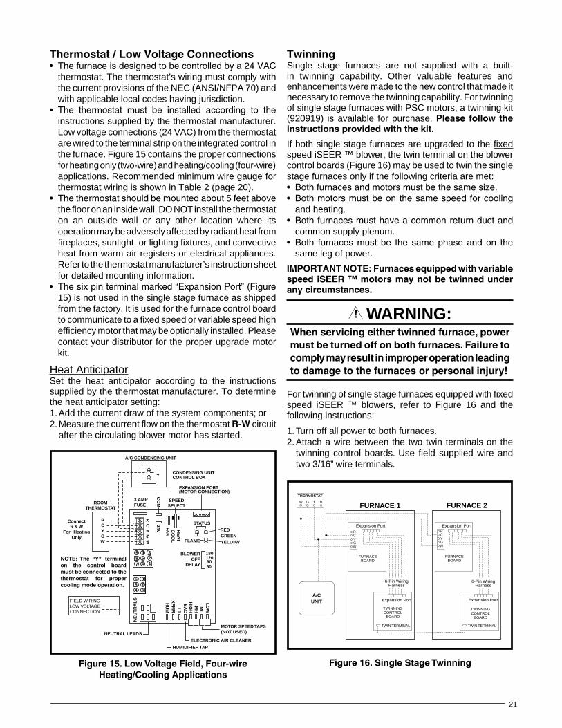
• The thermostat must be installed according to theinstructions supplied by the thermostat manufacturer. Low voltage connections (24 VAC) from the thermostat are wired to the terminal strip on the integrated control in the furnace. Figure 15 contains the proper connections for heating only (two-wire) and heating/cooling (four-wire) applications. Recommended minimum wire gauge for thermostat wiring is shown in Table 2 (page 20).
• Thethermostatshouldbemountedabout5feetabovethe floor on an inside wall. DO NOT install the thermostat on an outside wall or any other location where its operation may be adversely affected by radiant heat from fireplaces, sunlight, or lighting fixtures, and convective heat from warm air registers or electrical appliances. Refer to the thermostat manufacturer’s instruction sheet for detailed mounting information.
• Thesixpinterminalmarked“ExpansionPort”(Figure15) is not used in the single stage furnace as shipped from the factory. It is used for the furnace control board to communicate to a fixed speed or variable speed high efficiency motor that may be optionally installed. Please contact your distributor for the proper upgrade motor kit.
Heat AnticipatorSet the heat anticipator according to the instructions supplied by the thermostat manufacturer. To determine the heat anticipator setting:1. Add the current draw of the system components; or2. Measure the current flow on the thermostat R-W circuit
after the circulating blower motor has started.
TwinningSingle stage furnaces are not supplied with a built-in twinning capability. Other valuable features and enhancements were made to the new control that made it necessary to remove the twinning capability. For twinning of single stage furnaces with PSC motors, a twinning kit (920919) is available for purchase. Please follow theinstructionsprovidedwiththekit.
If both single stage furnaces are upgraded to the fixed speed iSEER ™ blower, the twin terminal on the blower control boards (Figure 16) may be used to twin the single stage furnaces only if the following criteria are met:• Bothfurnacesandmotorsmustbethesamesize.• Bothmotorsmustbeonthesamespeedforcooling
and heating.• Bothfurnacesmusthaveacommonreturnductand
common supply plenum.• Both furnaces must be the same phase and on the
same leg of power.
IMPORTANTNOTE:FurnacesequippedwithvariablespeediSEER™motorsmaynotbetwinnedunderanycircumstances.
wARNING:Whenservicingeithertwinnedfurnace,powermustbeturnedoffonbothfurnaces.Failuretocomplymayresultinimproperoperationleadingtodamagetothefurnacesorpersonalinjury!
For twinning of single stage furnaces equipped with fixed speed iSEER ™ blowers, refer to Figure 16 and the following instructions:
1. Turn off all power to both furnaces.2. Attach a wire between the two twin terminals on the
twinning control boards. Use field supplied wire and two 3/16” wire terminals.
TWIN TERMINAL
FURNACE 1
6-Pin Wiring Harness
TWINNINGCONTROL
BOARD
FURNACEBOARD
FURNACE 2
TWIN TERMINAL
TWINNINGCONTROL
BOARD
FURNACEBOARD
Expansion Port
6-Pin Wiring Harness
Expansion Port
Expansion Port
Expansion Port
WGYCR
THERMOSTAT
W G Y R
A/CUNIT
WGYCR
Figure16.SingleStageTwinning

22
wARNING:Donotattempttodrillthegasorifices.Useonlyfactory supplied orifices. Improperly drilledorifices may cause fire, explosion, carbonmonoxidepoisoning,personalinjuryordeath.
6. Obtain the manifold pressure setting required for this installation by referring to Table 7 (page 32) for Propane or Tables 9 or 10 for Natural Gas (page 33).
Themanifoldpressuremustbesettotheappropriatevalueforeachinstallationbyaqualifiedinstaller,serviceagencyorthegassupplier.
7. Remove the regulator capscrew (Figure 17, page 23) from the INLET side of the regulator.
8. Slowly turn the adjustment screw inside the regulator to obtain the appropriate manifold pressure.
NOTE: Turning the screw clockwise increases the pressure and turning the screw counter-clockwise decreases the pressure. To prevent backing the screw all the way out from the valve, turn the screw slowly.
9. Replace and tighten the regulator capscrew over the adjustment screw.
Verifying&AdjustingTemperatureRiseAfter installation of the furnace, confirm the temperature rise of the furnace is within the limits specified on the rating plate. Any temperature rise outside the specified limits could result in premature failure of the heat exchanger.
START-UP&ADJUSTMENTSPre-StartCheckList√ Verify the polarity of the connections are correct, the
line voltage power leads are securely connected and the furnace is properly grounded.
√ Verify the thermostat wires (R, w, Y, & G) are securely connected to the correct leads on the terminal strip of the circuit board.
√ Verify the gas line service pressure does not exceed 10.0 inches of W.C., and is not less than 4.5 inches W.C. for natural gas. For LP gas the line service pressure must not exceed 14 in. W.C., and must not be less than 11.0 in. W.C.
√ Verify the roll-out and manual reset switch is closed. If necessary, press the red button to reset a switch. DO NOT install a jumper wire across a switch to defeat its function. If a switch reopens on startup, DO NOT reset the switch without identifying and correcting the fault condition.
√ Verify the blower door is in place, closing the door switch in the line voltage circuit.
√ Verify the gas line has been purged and all connections are leak free.
Start-upProceduresDo not perform these steps until all of the checks in the previous steps have been completed:1. Set the thermostat to the lowest setting.2. Turn off all electrical power to the furnace.3. Follow the Operating Instructions on the label attached
to the furnace.4. Set the thermostat above room temperature and verify
the Operating Sequence (Page 23).5. After 5 minutes of operation, set the thermostat below
room temperature and verify steps 9 - 10 of the Operating Sequence.
Example:• Timefor1revolutionofagasmeterwitha1cubic
ft dial = 40 seconds.• FromTable5read90cubicftgasperhr.• Localheatingvalueofthegas(obtainedfromgas
supplier) = 1,040 Btu per cubic ft.• Inputrate=1,040x90=93,600Btuh.
Verifying&AdjustingInputRateThe input rate must be verified for each installation to prevent over-firing of the furnace. NOTE: The input rate must not exceed the rate shown on the furnace rating plate. At altitudes above 2,000 feet, it must not exceed that on the rating plate less 4% for each 1,000 feet. To determine the exact input rate, perform the following procedures:
1. Shut off all other gas fired appliances.2. Start the furnace and run it for at least 3 minutes.3. Measure the time (in seconds) required for the gas
meter to complete one revolution.4. Convert the time per revolution to cubic feet of gas per
hour using Table 5 (page 31).5. Multiply the gas flow rate in cubic ft per hr by the heating
value of the gas in Btu per cubic ft to obtain the input rate in Btuh. See example.
NOTE: One furnace can be used for one stage of heating and the other furnace can be used for the second stage of heating. The installer also has the choice of running one furnace only or both furnaces. In both cases the blowers will run at the same time and at the same speeds:• Single stage heating: The w connection on each furnace
must be connected together and then connected to the w connection of the thermostat. This will allow both furnaces to ignite at the same time for one stage heating.
• Two stage heating: The w connection on one furnace must be connected to the w1 connection of the thermostat. The w connection of the second furnace must be connected to the w2 connection of the thermostat. This will allow one furnace to ignite for one stage of heating and the second furnace to ignite for the second stage of heating.
3. Refer to Figure 16 (page 21) for the remaining thermostat connections. The C connection must be made between the twinned furnaces to ensure proper performance.
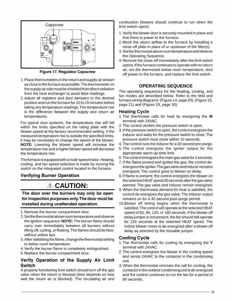
23
1. Place thermometers in the return and supply air stream as close to the furnace as possible. The thermometer on the supply air side must be shielded from direct radiation from the heat exchanger to avoid false readings.
2. Adjust all registers and duct dampers to the desired position and run the furnace for 10 to 15 minutes before taking any temperature readings. The temperature rise is the difference between the supply and return air temperatures.
For typical duct systems, the temperature rise will fall within the limits specified on the rating plate with the blower speed at the factory recommended setting. If the measured temperature rise is outside the specified limits, it may be necessary to change the speed of the blower. NOTE: Lowering the blower speed will increase the temperature rise and a higher blower speed will decrease the temperature rise.
The furnace is equipped with a multi-speed motor. Heating, cooling, and fan speed selection is made by moving the switch on the integrated control located in the furnace.
VerifyingBurnerOperation
CAUTION:Thedoorovertheburnersmayonlybeopenforinspectionpurposesonly.Thedoormustbeinstalledduringunattendedoperation.
1. Remove the burner compartment door.2. Set the thermostat above room temperature and observe
the ignition sequence. NOTE: The burner flame should carry over immediately between all burners without lifting off, curling, or floating. The flames should be blue, without yellow tips.
3. After validating the flame, change the thermostat setting to below room temperature.
4. Verify the burner flame is completely extinguished.5. Replace the burner compartment door.
Verify Operation of the Supply Air LimitSwitchA properly functioning limit switch should turn off the gas valve when the return is blocked (time depends on how well the return air is blocked). The circulating air and
combustion blowers should continue to run when the limit switch opens.
1. Verify the blower door is securely mounted in place and that there is power to the furnace.
2. Block the return airflow to the furnace by installing a close-off plate in place of or upstream of the filter(s).
3. Set the thermostat above room temperature and observe the Operating Sequence.
4. Remove the close-off immediately after the limit switch opens. If the furnace continues to operate with no return air, set the thermostat below room temperature, shut off power to the furnace, and replace the limit switch.
OpERATING SEQUENCEThe operating sequences for the heating, cooling, and fan modes are described below. Refer to the field and furnace wiring diagrams: (Figure 14, page 20), (Figure 15, page 21) and (Figure 19, page 30).
Heating Cycle1. The thermostat calls for heat by energizing the w
terminal with 24VAC.2. The control verifies the pressure switch is open.3. If the pressure switch is open, the control energizes the
inducer and waits for the pressure switch to close. The pressure switch must close within 10 seconds.
4. The control runs the inducer for a 30 second pre-purge.5. The control energizes the igniter output for the
appropriate warm-up time limit.6. The control energizes the main gas valve for 3 seconds.7. If the flame proved and ignites the gas, the control de-
energizes the igniter. The gas valve and inducer remains energized. The control goes to blower on delay.
8. If flame is present, the control energizes the blower on the selected HEAT speed 30 seconds after the gas valve opened. The gas valve and inducer remain energized.
9. When the thermostat demand for heat is satisfied, the control de-energizes the gas valve. The inducer output remains on for a 30 second post-purge period.
10. Blower off timing begins when the thermostat is satisfied. The control will operate at the selected HEAT speed of 60, 90, 120, or 180 seconds. If the blower off delay jumper is not present, the fan should still operate for 120 seconds at the selected HEAT speed. The Indoor blower motor is de-energized after a blower off delay as selected by the movable jumper.
CoolingCycle1. The thermostat calls for cooling by energizing the Y
terminal with 24VAC.2. The control energizes the blower in the cooling speed
and sends 24VAC to the contactor in the condensing unit.
3. When the thermostat removes the call for cooling, the contactor in the outdoor condensing unit is de-energized and the control continues to run the fan for a period of 60 seconds.
Capscrew
Figure17.RegulatorCapscrew
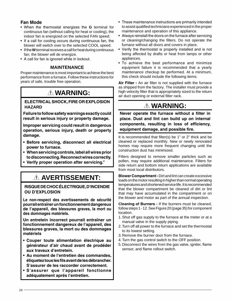
24
FanMode• When the thermostat energizes the G terminal for
continuous fan (without calling for heat or cooling), the indoor fan is energized on the selected FAN speed.
• Ifacallforcoolingoccursduringcontinuousfan,theblower will switch over to the selected COOL speed.
• Ifthew terminal receives a call for heat during continuous fan, the blower will de energize.
• Acallforfanisignoredwhileinlockout.
MAINTENANCEProper maintenance is most important to achieve the best performance from a furnace. Follow these instructions for years of safe, trouble free operation.
ELECTRICALSHOCK,FIREOREXPLOSIONHAzARD
Failuretofollowsafetywarningsexactlycouldresultinseriousinjuryorpropertydamage.
Improperservicingcouldresultindangerousoperation, serious injury, death or propertydamage.
• Before servicing, disconnect all electricalpowertofurnace.
• Whenservicingcontrols,labelallwirespriortodisconnecting.Reconnectwirescorrectly.
• Verifyproperoperationafterservicing.”
wARNING:
RISQUEDECHOCÉLECTRIQUE,D’INCENDIEOUD’EXPLOSION
Le non-respect des avertissements de sécuritépourraitentraînerunfonctionnementdangereuxde l’appareil,desblessuresgraves, lamortoudesdommagesmatériels.
Unentretein incorrectpourraitentraînerunfonctionnementdangereuxdel’appareil,desblessuresgraves,lamortoudesdommagesmatériels
• Couper toute alimentation électrique augénérateurd’airchaudavantdeprodéderauxtravauxd’entretein.
• Aumomentdel’entretiendescommandes,étiqueteztouslesfilsavantdelesdébrancher.S’assurerdelesraccordercorrectement.
• S’assurer que l’appareil fonctionneadéquatementaprésl’entretien.
AVERTISSEMENT:
• Thesemaintenanceinstructionsareprimarilyintendedto assist qualified technicians experienced in the proper maintenance and operation of this appliance.
• Alwaysreinstallthedoorsonthefurnaceafterservicingor cleaning/changing the filters. Do not operate the furnace without all doors and covers in place.
• Verify the thermostat isproperly installedand isnotbeing affected by drafts or heat from lamps or other appliances.
• To achieve the best performance and minimizeequipment failure it is recommended that a yearly maintenance checkup be performed. At a minimum, this check should include the following items:
AirFilter- An air filter is not supplied with the furnace as shipped from the factory. The installer must provide a high velocity filter that is appropriately sized to the return air duct opening or external filter rack.
wARNING:Never operate the furnace without a filter inplace.Dustand lintcanbuildupon internalcomponents, resulting in loss of efficiency,equipmentdamage,andpossiblefire.
It is recommended that filter(s) be 1” or 2” thick and be cleaned or replaced monthly. New or newly renovated homes may require more frequent changing until the construction dust has minimized.
Filters designed to remove smaller particles such as pollen, may require additional maintenance. Filters for side return and bottom return applications are available from most local distributors.
BlowerCompartment- Dirt and lint can create excessive loads on the motor resulting in higher than normal operating temperatures and shortened service life. It is recommended that the blower compartment be cleaned of dirt or lint that may have accumulated in the compartment or on the blower and motor as part of the annual inspection.
CleaningofBurners- If the burners must be cleaned, follow steps 1 - 12. See Figure 20 (page 35) for component location.1. Shut off gas supply to the furnace at the meter or at a
manual valve in the supply piping.2. Turn off all power to the furnace and set the thermostat
to its lowest setting.3. Remove the burner door from the furnace.4. Turn the gas control switch to the OFF position.5. Disconnect the wires from the gas valve, igniter, flame
sensor, and flame rollout switch.
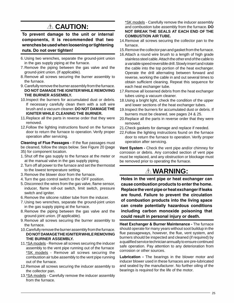
25
CAUTION:To prevent damage to the unit or internalcomponents, it is recommended that twowrenchesbeusedwhenlooseningortighteningnuts.Donotovertighten!
6. Using two wrenches, separate the ground-joint union in the gas supply piping at the furnace.
7. Remove the piping between the gas valve and the ground-joint union. (If applicable).
8. Remove all screws securing the burner assembly to the furnace.
9. Carefully remove the burner assembly from the furnace. DO NOT DAMAGE THE IGNITER wHILE REMOVING THE BURNER ASSEMBLY.
10. Inspect the burners for accumulated dust or debris. If necessary carefully clean them with a soft wire brush and a vacuum cleaner. DO NOT DAMAGE THE IGNITER wHILE CLEANING THE BURNER.
11. Replace all the parts in reverse order that they were removed.
12. Follow the lighting instructions found on the furnace door to return the furnace to operation. Verify proper operation after servicing.
CleaningofFluePassages- If the flue passages must be cleaned, follow the steps below. See Figure 20 (page 35) for component location.1. Shut off the gas supply to the furnace at the meter or
at the manual valve in the gas supply piping.2. Turn off all power to the furnace and set the thermostat
to the lowest temperature setting.3. Remove the blower door from the furnace.4. Turn the gas control switch to the OFF position.5. Disconnect the wires from the gas valve, flame sensor,
inducer, flame roll-out switch, limit switch, pressure switch and igniter.
6. Remove the silicone rubber tube from the inducer.7. Using two wrenches, separate the ground-joint union
in the gas supply piping at the furnace.8. Remove the piping between the gas valve and the
ground-joint union. (If applicable).9. Remove all screws securing the burner assembly to
the furnace.10. Carefully remove the burner assembly from the furnace.
DO NOT DAMAGE THE IGNITER wHILE REMOVING THE BURNER ASSEMBLY.
11. *SA models - Remove all screws securing the inducer assembly to the vent pipe running out of the furnace
*SK models - Remove all screws securing the combustion air tube assembly to the vent pipe running out of the furnace.
12. Remove all screws securing the inducer assembly to the collector pan.
13. *SA models - Carefully remove the inducer assembly from the furnace.
*SK models - Carefully remove the inducer assembly and combustion tube assembly from the furnace. DO NOT BREAK THE SEALS AT EACH END OF THE COMBUSTION AIR TUBE.
14. Remove all screws securing the collector pan to the furnace.
15. Remove the collector pan and gasket from the furnace.16. Attach a round wire brush to a length of high grade
stainless steel cable. Attach the other end of the cable to a variable speed reversible drill. Slowly insert and rotate the cable into the top portion of the heat exchanger. Operate the drill alternating between forward and reverse, working the cable in and out several times to obtain sufficient cleaning. Repeat this sequence for each heat exchanger tube.
17. Remove all loosened debris from the heat exchanger tubes using a vacuum cleaner.
18. Using a bright light, check the condition of the upper and lower sections of the heat exchanger tubes.
19. Inspect the burners for accumulated dust or debris. If burners must be cleaned, see pages 24 & 25.
20. Replace all the parts in reverse order that they were removed.
21. Check gaskets for damage and replace if needed.22. Follow the lighting instructions found on the furnace
door to return the furnace to operation. Verify proper operation after servicing.
VentSystem- Check the vent pipe and/or chimney for corrosion or debris. Any corroded section of vent pipe must be replaced, and any obstruction or blockage must be removed prior to operating the furnace.
wARNING:Holesintheventpipeorheatexchangercancausecombustionproductstoenterthehome.Replacetheventpipeorheatexchangerifleaksare found. Failure to prevent the circulationofcombustionproductsintothelivingspacecan create potentially hazardous conditionsincluding carbon monoxide poisoning thatcouldresultinpersonalinjuryordeath.
HeatExchanger&BurnerMaintenance- The furnace should operate for many years without soot buildup in the flue passageways, however, the flue, vent system, and burners should be inspected and cleaned (if required) by a qualified service technician annually to ensure continued safe operation. Pay attention to any deterioration from corrosion or other sources.
Lubrication - The bearings in the blower motor and inducer blower used in these furnaces are pre-lubricated and sealed by the manufacturer. No further oiling of the bearings is required for the life of the motor.
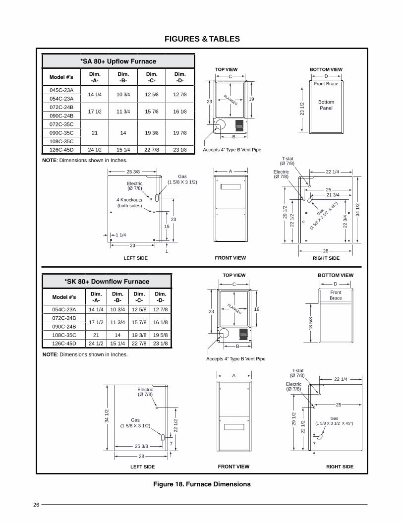
26
FIGURES & TABLES
Figure18.FurnaceDimensions
D
23 1
/2
A
23
15
1
25 3/8
C
19
B
23
22 3
/4
21 3/4
22 1/4
29 1
/2
22 1
/2
25
4 Knockouts(both sides)
LEFT SIDE RIGHT SIDE
BOTTOM VIEWTOP VIEW
Accepts 4” Type B Vent Pipe
23
1 1/4
FLANGES
T-stat(Ø 7/8)
Electric(Ø 7/8)
Gas
(1 5
/8 X 3
1/2
X 45
°)
Gas(1 5/8 X 3 1/2)Electric
(Ø 7/8)
FRONT VIEW
Front Brace
BottomPanel
34 1
/2
28
*SA80+UpflowFurnace
Model#’s Dim.-A-
Dim.-B-
Dim.-C-
Dim.-D-
045C-23A14 1/4 10 3/4 12 5/8 12 7/8
054C-23A
072C-24B17 1/2 11 3/4 15 7/8 16 1/8
090C-24B
072C-35C
21 14 19 3/8 19 7/8090C-35C
108C-35C
126C-45D 24 1/2 15 1/4 22 7/8 23 1/8
NOTE: Dimensions shown in Inches.
18 5
/8
C
7
34 1
/2
22 1
/2
28
25 3/8
22 1
/2
25
22 1/4
29 1
/2
23
B
7
Gas(1 5/8 X 3 1/2 X 45°)
T-stat(Ø 7/8)
Gas(1 5/8 X 3 1/2)
Electric(Ø 7/8)
FrontBrace
D
BOTTOM VIEW
RIGHT SIDELEFT SIDE
TOP VIEW
19
A
FRONT VIEW
FLANGES
Accepts 4” Type B Vent Pipe
Electric(Ø 7/8)
*SK80+DownflowFurnace
Model#’sDim.-A-
Dim.-B-
Dim.-C-
Dim.-D-
054C-23A 14 1/4 10 3/4 12 5/8 12 7/8
072C-24B17 1/2 11 3/4 15 7/8 16 1/8
090C-24B
108C-35C 21 14 19 3/8 19 5/8
126C-45D 24 1/2 15 1/4 22 7/8 23 1/8
NOTE: Dimensions shown in Inches.

27
AIRFLOw DATA
*SA-UPFLOW/HORIZONTALFURNACES-80+AFUEModelNumber
&HeatingInput
(Btuh)
MotorSpeed
ExternalStaticPressure(InchesWaterColumn)
0.1 0.2 0.3 0.4 0.5 0.6 0.7 0.8
CFM Rise CFM Rise CFM Rise CFM Rise CFM Rise CFM Rise CFM Rise CFM Rise
SA045C-23ABottom Return
(45,000)
High* 1,260 26 1,205 28 1,145 29 1,080 31 1,025 33 960 35 890 37 825 40
Med-High 955 35 950 35 940 35 935 36 925 36 860 39 800 42 725 46
Med-Low** 825 40 800 42 760 44 730 46 690 48 650 51 600 56 530 63
Low 655 51 630 53 610 55 580 57 550 61 520 64 480 69 435 77
SA045C-23ASide Return
(45,000)
High* 1,350 25 1,290 26 1,225 27 1,155 29 1,100 30 1,025 33 950 35 885 38
Med-High 1,025 33 1,015 33 1,005 33 1,000 33 990 34 920 36 855 39 775 43
Med-Low** 885 38 855 39 815 41 780 43 740 45 695 48 640 52 565 59
Low 700 48 675 49 655 51 620 54 590 56 555 60 515 65 465 72
SA054C-23ABottom Return
(54,000)
High* 1,260 32 1,205 33 1,145 35 1,080 37 1,025 39 960 42 890 45 825 48
Med-High** 955 42 950 42 940 43 935 43 925 43 860 47 800 50 725 55
Med-Low 825 48 800 50 760 53 730 55 690 58 650 62 600 67 530 75
Low 655 61 630 63 610 66 580 69 550 73 520 77 480 83 435 92
SA054C-23ASide Return
(54,000)
High* 1,350 30 1,290 31 1,225 33 1,155 35 1,100 36 1,025 39 950 42 885 45
Med-High** 1,025 39 1,015 39 1,005 40 1,000 40 990 40 920 43 855 47 775 52
Med-Low 885 45 855 47 815 49 780 51 740 54 695 58 640 63 565 71
Low 700 57 675 59 655 61 620 65 590 68 555 72 515 78 465 86
SA072C)-24BBottom Return
(72,000)
High* 1,685 32 1,640 33 1,605 33 1,565 34 1,515 35 1,475 36 1,415 38 1,345 40
Med-High 1,330 40 1,295 41 1,275 42 1,245 43 1,215 44 1,185 45 1,135 47 1,070 50
Med-Low** 1,175 45 1,155 46 1,125 47 1,100 48 1,075 50 1,045 51 1,010 53 955 56
Low 930 57 895 60 885 60 850 63 825 65 800 67 770 69 740 72
SA072C-24BSide Return
(72,000)
High* 1,770 30 1,720 31 1,685 32 1,645 32 1,590 34 1,550 34 1,485 36 1,415 38
Med-High 1,400 38 1,360 39 1,340 40 1,310 41 1,275 42 1,245 43 1,190 45 1,125 47
Med-Low** 1,235 43 1,215 44 1,180 45 1,155 46 1,130 47 1,100 48 1,060 50 1,005 53
Low 975 55 940 57 930 57 890 60 865 62 840 63 810 66 775 69
SA090C-24BBottom Return
(90,000)
High* 1,610 41 1,575 42 1,530 44 1,485 45 1,440 46 1,385 48 1,340 50 1,275 52
Med-High** 1,295 51 1,260 53 1,235 54 1,220 55 1,175 57 1,135 59 1,095 61 1,015 66
Med-Low 1,155 58 1,130 59 1,100 61 1,070 62 1,035 64 1,015 66 965 69 920 72
Low 880 76 860 78 830 80 800 83 765 87 740 90 675 99 660 101
SA090C-24BSide Return
(90,000)
High* 1,690 39 1,655 40 1,610 41 1,560 43 1,510 44 1,455 46 1,405 47 1,340 50
Med-High** 1,360 49 1,325 50 1,300 51 1,280 52 1,235 54 1,190 56 1,150 58 1,065 63
Med-Low 1,215 55 1,190 56 1,155 58 1,125 59 1,090 61 1,065 63 1,015 66 965 69
Low 925 72 900 74 870 77 840 79 800 83 775 86 710 94 695 96
SA072C-35CBottom Return
(72,000)
High* 1,950 27 1,865 29 1,790 30 1,715 31 1,630 33 1,550 34 1,475 36 1,390 38
Med-High 1,860 29 1,780 30 1,710 31 1,635 33 1,575 34 1,500 36 1,415 38 1,325 40
Med-Low** 1,300 41 1,240 43 1,200 44 1,160 46 1,120 48 1,065 50 995 54 910 59
Low 1,165 46 1,115 48 1,060 50 1,025 52 985 54 940 57 890 60 825 65
SA072C-35CSide Return
(72,000)
High* 2,030 26 1,940 27 1,860 29 1,785 30 1,695 31 1,615 33 1,535 35 1,445 37
Med-High 1,935 28 1,850 29 1,780 30 1,700 31 1,340 40 1,560 34 1,470 36 1,380 39
Med-Low** 1,350 40 1,290 41 1,250 43 1,205 44 1,165 46 1,110 48 1,035 52 945 56
Low 1,215 44 1,160 46 1,105 48 1,065 50 1,025 52 980 54 925 58 860 62
SA072C-35CSide + Bottom
or 2 Sides(72,000)
High* 2,050 26 1,960 27 1,880 28 1,800 30 1,710 31 1,630 33 1,550 34 1,460 37
Med-High 1,955 27 1,870 29 1,800 30 1,715 31 1,655 32 1,575 34 1,485 36 1,390 38
Med-Low** 1,365 39 1,300 41 1,260 42 1,220 44 1,175 45 1,120 48 1,045 51 955 56
Low 1,225 44 1,170 46 1,115 48 1,075 50 1,035 52 985 54 935 57 865 62
Table3.MaximumAirflow&TemperatureRises(°F)-Upflow/HorizontalFurnaces

28
*SA-UPFLOW/HORIZONTALFURNACES-80+AFUE
ModelNumber
HeatingInput(Btuh)
MotorSpeed
ExternalStaticPressure(InchesWaterColumn)
0.1 0.2 0.3 0.4 0.5 0.6 0.7 0.8
CFM Rise CFM Rise CFM Rise CFM Rise CFM Rise CFM Rise CFM Rise CFM Rise
SA090C-35CBottom Return
(90,000)
High* 1,940 34 1,860 36 1,790 37 1,710 39 1,625 41 1,540 43 1,450 46 1,355 49
Med-High** 1,820 37 1,760 38 1,695 39 1,620 41 1,545 43 1,466 45 1,380 48 1,280 52
Med-Low 1,290 52 1,245 54 1,200 56 1,155 58 1,110 60 1,060 63 995 67 915 73
Low 1,145 58 1,110 60 1,070 62 1,035 64 1,000 67 950 70 905 74 835 80
SA090C-35CSide Return
(90,000)
High* 2,020 33 1,935 34 1,860 36 1,780 37 1,690 39 1,600 42 1,510 44 1,410 47
Med-High** 1,895 35 1,830 36 1,765 38 1,685 40 1,610 41 1,525 44 1,435 46 1,330 50
Med-Low 1,345 50 1,295 51 1,250 53 1,200 56 1,155 58 1,100 61 1,035 64 950 70
Low 1,190 56 1,155 58 1,115 60 1,075 62 1,040 64 980 68 940 71 870 77
SA090C-35CSide + Bottom
or 2 Sides(90,000)
High* 2,040 33 1,955 34 1,880 35 1,795 37 1,705 39 1,620 41 1,525 44 1,425 47
Med-High** 1,910 35 1,850 36 1,780 37 1,700 39 1,625 41 1,540 43 1,450 46 1,345 50
Med-Low 1,355 49 1,310 51 1,260 53 1,215 55 1,165 57 1,115 60 1,050 63 960 69
Low 1,205 55 1,165 57 1,125 59 1,085 61 1,050 63 1,000 67 950 70 875 76
SA108C-35CBottom Return
(108,000)
High* 2,205 36 2,150 37 2,095 38 2,030 39 1,970 41 1,900 42 1,830 44 1,740 46
Med-High** 2,050 39 1,995 40 1,955 41 1,895 42 1,840 43 1,775 45 1,700 47 1,610 50
Med-Low 1,700 47 1,680 48 1,645 49 1,610 50 1,565 51 1,525 52 1,460 55 1,375 58
Low 1,390 58 1,370 58 1,355 59 1,320 61 1,300 62 1,270 63 1,225 65 1,175 68
SA108C-35CSide Return(108,000)
High* 2,295 35 2,235 36 2,180 37 2,110 38 2,050 39 1,975 41 1,900 42 1,810 44
Med-High** 2,130 38 2,075 39 2,035 39 1,970 41 1,915 42 1,845 43 1,765 45 1,675 48
Med-Low 1,770 45 1,750 46 1,710 47 1,675 48 1,630 49 1,585 50 1,520 53 1,430 56
Low 1,445 55 1,425 56 1,410 57 1,375 58 1,350 59 1,320 61 1,275 63 1,225 65
SA108C-35CSide + Bottom
or 2 Sides(108,000)
High* 2,315 35 2,260 35 2,200 36 2,130 38 2,070 39 1,995 40 1,925 42 1,825 44
Med-High** 2,155 37 2,095 38 2,055 39 1,990 40 1,930 41 1,865 43 1,785 45 1,690 47
Med-Low 1,785 45 1,765 45 1,725 46 1,690 47 1,645 49 1,600 50 1,535 52 1,445 55
Low 1,460 55 1,440 56 1,425 56 1,385 58 1,365 59 1,335 60 1,285 62 1,235 65
SA126C-45DBottom only
or 2 openings(126,000)
High* 2,255 41 2,200 42 2,125 44 2,065 45 2,010 46 1,935 48 1,855 50 1,755 53
Med-High** 2,075 45 2,025 46 1,970 47 1,940 48 1,875 50 1,810 52 1,750 53 1,680 56
Med-Low 1,720 54 1,695 55 1,655 56 1,630 57 1,580 59 1,520 61 1,455 64 1,390 67
Low 1,360 69 1,375 68 1,365 68 1,315 71 1,310 71 1,300 72 1,260 74 1,230 76
SA126C-45DSide Return(126,000)
High* 2,230 42 2,180 43 2,105 44 2,045 46 1,990 47 1,915 49 1,835 51 1,740 54
Med-High** 2,055 45 2,005 47 1,950 48 1,920 49 1,855 50 1,790 52 1,735 54 1,665 56
Med-Low 1,705 55 1,680 56 1,640 57 1,615 58 1,565 60 1,505 62 1,440 65 1,375 68
Low 1,345 69 1,360 69 1,350 69 1,300 72 1,230 76 1,290 72 1,250 75 1,220 77
NOTES:
* Factory Set Cooling Speed
** Factory Set Heating Speed
1. Two openings are recommended for airflows above 1,600 CFM if filter(s) is(are) adjacent to furnace
2. Temperature rises in the table are approximate. Actual temperature rises may vary.
3. Temperature rises shaded in gray are for reference only. These conditions are not recommended.
Table3.Continued

29
*SK-DOWNFLOWFURNACES-80+AFUE
ModelNumber&
HeatingInput(Btuh)
MotorSpeed
ExternalStaticPressure(InchesWaterColumn)
0.1 0.2 0.3 0.4 0.5 0.6 0.7 0.8
CFM Rise CFM Rise CFM Rise CFM Rise CFM Rise CFM Rise CFM Rise CFM Rise
SK054C-23A(54,000)
High* 1,375 29 1,340 30 1,300 31 1,270 31 1,225 33 1,175 34 1,115 36 1,035 39
Med-High 1,155 35 1,130 35 1,110 36 1,085 37 1,055 38 1,015 39 975 41 910 44
Med-Low** 790 51 775 52 765 52 750 53 730 55 700 57 665 60 610 66
Low 650 62 640 63 630 63 610 66 590 68 565 71 530 75 480 83
SK072C-24B(72,000)
High* 1,675 32 1655 32 1640 33 1620 33 1590 34 1560 35 1520 35 1475 36
Med-High 1,330 40 1315 41 1300 41 1280 42 1255 42 1230 44 1200 44 1150 46
Med-Low** 1,180 45 1165 46 1150 46 1135 47 1115 48 1090 50 1060 50 1010 53
Low 940 57 925 58 900 59 880 61 850 63 825 65 795 67 760 70
SK090C-24B(90,000)
High* 1,610 41 1590 42 1575 42 1560 43 1540 43 1495 46 1460 46 1415 47
Med-High 1,295 51 1275 52 1260 53 1250 53 1220 55 1195 57 1170 57 1120 60
Med-Low** 1,155 58 1235 54 1115 60 1095 61 1065 63 1040 66 1015 66 980 68
Low 910 73 885 75 860 78 835 80 810 82 785 85 765 87 735 91
SK108C-35C(108,000)
High* 2,395 33 2,335 34 2,285 35 2,230 36 2,200 36 2,140 37 2,080 38 2,000 40
Med-High 2,190 37 2,135 37 2,115 38 2,080 38 2,030 39 1,975 41 1,915 42 1,810 44
Med-Low** 1,785 45 1,770 45 1,740 46 1,725 46 1,685 47 1,645 49 1,615 50 1,565 51
Low 1,145 70 1,110 72 1,070 75 1,035 77 1,000 80 950 84 905 88 835 96
SK126C-45D(126,000)
High* 2,445 38 2,395 39 2,385 39 2,330 40 2,275 41 2,225 42 2,130 44 2,015 46
Med-High 2,195 43 2,170 43 2,140 44 2,120 44 2,090 45 2,030 46 1,975 47 1,855 50
Med-Low** 1,795 52 1,780 52 1,770 53 1,760 53 1,725 54 1,690 55 1,655 56 1,610 58
Low 1,480 63 1,475 63 1,450 64 1,440 65 1,440 65 1,415 66 1,405 66 1,375 68
NOTES:
* Factory Set Cooling Speed
** Factory Set Heating Speed
1. Temperature rises in the table are approximate. Actual temperature rises may vary.
2. Temperature rises shaded gray are for reference only. These conditions are not recommended.
Table4.MaximumAirflow&TemperatureRises(°F)-DownflowFurnaces

30
ELECTRICAL INFORMATION
Figure19.WiringDiagramforUpflow&DownflowFurnaces
7109
15C
04/1
1
FIE
LD W
IRIN
G
LEG
EN
D:
LOW
VO
LTA
GE
HIG
H V
OLT
AG
E
WIR
ING
DIA
GR
AM
For
80+
and
90+
Sin
gle
Sta
ge F
urna
ces
Ref
er to
the
Inst
alla
tion
Inst
ruct
ions
prov
ided
with
the
furn
ace
for
the
prop
er h
eatin
g an
d co
olin
g sp
eeds
for
your
app
licat
ion.
If an
y of
the
orig
inal
wir
e as
sup
plie
d w
ithth
e fu
rnac
e m
ust b
e re
plac
ed, i
t mus
t be
repl
aced
with
wir
ing
mat
eria
l hav
ing
ate
mpe
ratu
re o
f at l
east
105
C.
Use
cop
per
cond
ucto
rs o
nly.
Dia
gnos
tic D
escr
iptio
nG
reen
LE
DR
ed L
ED
Con
trol
Fau
lt (N
o P
ower
)O
ffO
ffL1
/ N
eutr
al P
olar
ity F
ault
Fla
shF
lash
1 H
our
Lock
out
nO
nO
noitarepO la
mroN P
ress
ure
Sw
itch
Clo
sed
Fau
ltO
nF
lash
Pre
ssur
e S
witc
h O
pen
Fau
ltF
lash
On
Ope
n Li
mit
Sw
itch
Fau
ltF
lash
Off
Dia
gnos
tic D
escr
iptio
nLo
w F
lam
e S
enso
r S
igna
lF
lam
e P
rese
nt
FAU
LT C
ON
DIT
ION
S
Yel
low
LE
DC
ontin
uous
Fla
shO
n
Alte
rnat
ing
Fla
sh
(Rep
lace
s 71
0915
B)
IGN
ITO
R
IND
UC
ER
FLA
ME
SE
NS
OR
C
BLO
WE
RLI
MIT
DO
OR
SW
ITC
H
R
4 S
PE
ED
MO
TOR
WHITE
RED
BLUE
ORANGE
BLACK
GA
SVA
LVE
H
MH
ML
L
C
FLAMEROLLOUT
SU
PP
LYA
IR L
IMIT
VENT LIMIT SWITCH(ON SELECT MODELS)
R C Y G W
LOW
ML
MH
HIGH
EAC
L1
XFMR
HUM
123
456
789
123
456
CO
M
GR
EE
N YE
LLO
W
RE
D
3 A
MP
FU
SE
24V
12
34
24 V
120
V
WH
ITE
BLA
CK
WH
ITE
W/ B
LK S
TR
IPE
S
BLK
W/ W
HIT
E S
TR
IPE
S
12
34
12
34
RC
TXRXW
COM
11
22
33
44
55
66
77
88
99
L1A
NEUTRALS
1 21 2 1 2
1 2
GR
EE
N
BLA
CK
WH
ITE
OR
AN
GE
BLUE
YE
LLO
W
RE
DO
RA
NG
E
BLA
CK
WH
ITE
BLU
E
ORANGE
BLA
CK
RE
D
BLA
CK B
LAC
KB
LAC
K
BLU
E
BLU
EB
LUE
BLU
E
BLUE
GR
EE
N
BLUE
BLACK
BLO
WE
RD
EC
K L
IMIT
(ON
SE
LEC
TM
OD
ELS
)
BLO
WE
RLI
MIT
PR
ES
SU
RE
SW
ITC
H(O
N S
ELE
CT
MO
DE
LS)
PR
ES
SU
RE
SW
ITC
H
BLUEBLUE
SIN
GLE
STA
GE
TH
ER
MO
STA
T
TO OUTDOOR UNIT
WH
ITE
(N
EU
TR
AL)
BLA
CK
120
VG
RO
UN
D
ORANGE
BLACK
WHITE
BLA
CK
WH
ITE
YE
LLO
W

31
GAS INFORMATION
GAS pIpE CApACITIES
NominalPipeDiameter(IN.)
LengthofPipeRun(Feet)
10 20 30 40 50 60 70 80
1/2 130 90 75 65 55 50 45 40
3/4 280 190 150 130 115 105 95 90
1 520 350 285 245 215 195 180 170
1 1/4 1,050 730 590 500 440 400 370 350
1 1/2 1,600 1,100 890 760 670 610
NOTE: The cubic feet per hour listed in the table above must be greater than the cubic feet per hour of gas flow required by the furnace. To determine the cubic feet per hour of gas flow required by the furnace, divide the input rate of the furnace by the heating value (from gas supplier) of the gas.
Cubic Feet Per Hour Required =Input To Furnace (Btu/hr)
Heating Value of Gas (Btu/Cu. Ft.)
Table6.CapacityofBlackIronGasPipe(cu.ft.perhour)forNaturalGasw/SpecificGravity=0.60
GAS FLOw RATES
TIME FORONE REVOLUTION
(SECONDS)
CUBIC FEET pERREVOLUTION OF GAS METER
1 5 10
10 360 1,800 3,600
12 300 1,500 3,000
14 257 1,286 2,571
16 225 1,125 2,250
18 200 1,000 2,000
20 180 900 1,800
22 164 818 1,636
24 150 750 1,500
26 138 692 1,385
28 129 643 1,286
30 120 600 1,200
32 113 563 1,125
34 106 529 1,059
36 100 500 1,000
38 95 474 947
40 90 450 900
42 86 429 857
44 82 409 818
46 78 391 783
48 75 375 750
50 72 360 720
52 69 346 692
54 67 333 667
56 64 321 643
58 62 310 621
60 60 300 600
62 58 290 581
64 56 281 563
Table5.GasFlowRates(CubicFeetperHour)
GAS FLOw RATES
TIME FORONE REVOLUTION
(SECONDS)
CUBIC FEET pERREVOLUTION OF GAS METER
1 5 10
66 55 273 545
68 53 265 529
70 51 257 514
72 50 250 500
74 49 243 486
76 47 237 474
78 46 231 462
80 45 225 450
82 44 220 439
84 43 214 429
86 42 209 419
88 41 205 409
90 40 200 400
92 39 196 391
94 38 191 383
96 38 188 375
98 37 184 367
100 36 180 360
102 35 176 353
104 35 173 346
106 34 170 340
108 33 167 333
110 33 164 327
112 32 161 321
114 32 158 316
116 31 155 310
118 31 153 305
120 30 150 300

32
Table7.HighAltitudeDerationChartforPropaneGas
pROpANE DERATION CHART
ALTITUDE ABOVE SEA LEVEL
INPUT(BTU)
45,000 54,000 72,000 90,000 108,000 126,000
0to1,999FT57 56 56 56 56 56 ORIFICE SIZE
10.0 10.0 10.0 10.0 10.0 10.0 MANIFOLD PRESSURE
2,000to2,999FT57 56 56 56 56 56 ORIFICE SIZE
9.0 9.0 9.0 9.0 9.0 9.0 MANIFOLD PRESSURE
3,000to4,999FT57 56 56 56 56 56 ORIFICE SIZE
8.5 8.5 8.5 8.5 8.5 8.5 MANIFOLD PRESSURE
5,000to5,999FT59 57 57 57 57 57 ORIFICE SIZE
10.0 10.0 10.0 10.0 10.0 10.0 MANIFOLD PRESSURE
6,000to7,999FT59 57 57 57 57 57 ORIFICE SIZE
9.0 9.0 9.0 9.0 9.0 9.0 MANIFOLD PRESSURE
8,000to10,000FT59 57 57 57 57 57 ORIFICE SIZE
8.5 8.5 8.5 8.5 8.5 8.5 MANIFOLD PRESSURE
LOCAL HEATING VALUES FOR NATURAL GAS
ALTITUDE ABOVE SEA LEVEL
BTU pER CUBIC FOOT
650 700 750 800 850 900 950 1,000 1,050
2,000 FT LOW LOW LOW LOW LOW LOW HIGH HIGH HIGH
3,000 FT LOW LOW LOW LOW LOW LOW HIGH HIGH HIGH
4,000 FT LOW LOW LOW LOW LOW HIGH HIGH HIGH HIGH
5,000 FT LOW LOW LOW LOW LOW HIGH HIGH HIGH HIGH
6,000 FT LOW LOW LOW LOW HIGH HIGH HIGH HIGH HIGH
7,000 FT LOW LOW LOW LOW HIGH HIGH HIGH HIGH HIGH
8,000 FT LOW LOW LOW HIGH HIGH HIGH HIGH HIGH HIGH
9,000 FT LOW LOW LOW HIGH HIGH HIGH HIGH HIGH HIGH
10,000 FT LOW LOW HIGH HIGH HIGH HIGH HIGH HIGH HIGH
Table8.NaturalGasHeatingValues

33
Table9.HighAltitudeDerationChartforNaturalGas-HighHeatingValue
NATURALGASw/HIGHHEATINGVALUE
ALTITUDE ABOVE SEA LEVEL
INPUT(BTU)
45,000 54,000 72,000 90,000 108,000 126,000
0 to 1,999 FT49 47 47 47 47 47 ORIFICE SIZE
3.5 3.5 3.5 3.5 3.5 3.5 MANIFOLD PRESSURE
2,000 to 2,999 FT49 47 47 47 47 47 ORIFICE SIZE
2.9 3.2 3.2 3.2 3.2 3.2 MANIFOLD PRESSURE
3,000 to 3,999 FT49 47 47 47 47 47 ORIFICE SIZE
2.8 3.0 3.0 3.0 3.0 3.0 MANIFOLD PRESSURE
4,000 to 4,999 FT49 47 47 47 47 47 ORIFICE SIZE
2.6 2.8 2.8 2.8 2.8 2.8 MANIFOLD PRESSURE
5,000 to 5,999 FT49 47 47 47 47 47 ORIFICE SIZE
2.5 2.7 2.7 2.7 2.7 2.7 MANIFOLD PRESSURE
6,000 to 6,999 FT51 49 49 49 49 49 ORIFICE SIZE
3.3 3.5 3.5 3.5 3.5 3.5 MANIFOLD PRESSURE
7,000 to 7,999 FT51 49 49 49 49 49 ORIFICE SIZE
3.0 3.3 3.3 3.3 3.3 3.3 MANIFOLD PRESSURE
8,000 to 8,999 FT51 49 49 49 49 49 ORIFICE SIZE
2.8 3.0 3.0 3.0 3.0 3.0 MANIFOLD PRESSURE
9,000 to 9,999 FT51 49 49 49 49 49 ORIFICE SIZE
2.6 2.8 2.8 2.8 2.8 2.8 MANIFOLD PRESSURE
Table10.HighAltitudeDerationChartforNaturalGas-LowHeatingValue
NATURALGASw/LOWHEATINGVALUE
ALTITUDE ABOVE SEA LEVEL
INPUT(BTU)
45,000 54,000 72,000 90,000 108,000 126,000
0 to 1,999 FT49 47 47 47 47 47 ORIFICE SIZE
3.5 3.5 3.5 3.5 3.5 3.5 MANIFOLD PRESSURE
2,000 to 2,999 FT49 47 47 47 47 47 ORIFICE SIZE
3.5 3.5 3.5 3.5 3.5 3.5 MANIFOLD PRESSURE
3,000 to 3,999 FT49 47 47 47 47 47 ORIFICE SIZE
3.1 3.3 3.3 3.3 3.3 3.3 MANIFOLD PRESSURE
4,000 to 4,999 FT49 47 47 47 47 47 ORIFICE SIZE
2.9 3.1 3.1 3.1 3.1 3.1 MANIFOLD PRESSURE
5,000 to 5,999 FT49 47 47 47 47 47 ORIFICE SIZE
2.7 2.9 2.9 2.9 2.9 2.9 MANIFOLD PRESSURE
6,000 to 6,999 FT49 47 47 47 47 47 ORIFICE SIZE
2.6 2.8 2.8 2.8 2.8 2.8 MANIFOLD PRESSURE
7,000 to 7,999 FT51 49 49 49 49 49 ORIFICE SIZE
3.4 3.4 3.4 3.4 3.4 3.4 MANIFOLD PRESSURE
8,000 to 8,999 FT51 49 49 49 49 49 ORIFICE SIZE
3.1 3.2 3.2 3.2 3.2 3.2 MANIFOLD PRESSURE
9,000 to 9,999 FT51 49 49 49 49 49 ORIFICE SIZE
2.9 2.9 2.9 2.9 2.9 2.9 MANIFOLD PRESSURE

34
TROUBLESHOOTINGIfthefurnacefailstooperatecheckthefollowing:• Isthethermostatoperatingproperly?• Aretheblowercompartmentdoor(s)inplace?• Isthefurnacedisconnectclosed?• Hasthecircuitbreakertrippedorthecontrolboardfuse
burnedopen?• Isthegasturnedon?• Areanymanualresetswitchesopen?• Isthefilterdirtyorplugged?• Istheflamesensorcoated?(Removeandcleanwith
steel wool).• ArealltheLED’sonthefurnacecontrolboardconstantly
ON?Ifnot,refertoTable11orthewiringdiagram(Figure19, page 30) to determine fault condition.
IMPORTANTNOTE:Thefurnacewilllockoutafter5failedattemptsfor ignitionandwill tryagaineveryhourifthecallforheatremains.
• Iftheinducerblowerisoperatinganditemsabovehavebeen verified, check the blower limit switch and reset if necessary. See Figure 20 (page 35) for component location.
DiagnosticDescription Green LED RedLED
Control Fault (No Power) Off Off
L1/Neutral Polarity Fault Flash Flash
1 Hour Lockout Alternating Flash
Normal Operation On On
Pressure Switch Closed Fault On Flash
Pressure Switch Open Fault Flash On
Open Limit Switch Fault Flash Off
Motor Fault On Off
DiagnosticDescription YellowLED
Low Flame Sensor Signal Continuous Flash
Flame Present On
Table11.ControlBoardFaultConditions
• Ifthefurnaceoperateswhentheblowerlimitswitchisreset, contact a qualified service technician to identify and repair the problem.
• If the furnace still doesn’t operate, check the flameroll-out switch and reset if necessary. See Figure 20 for component location.
• Ifthefurnaceoperateswhentheflamerolloutswitchisreset, contact a qualified service technician to identify and repair the problem.
FURNACE COMpONENTSThe descriptions below are various functional components that affect the operation and shutting down of this furnace. Some of these components and their locations are shown in Figure 20 (page 35). If any component of the furnace must be replaced, use only factory authorized replacement parts specified in the Replacement Parts List provided online.
BlowerLimitSwitch- Prevents operation when blower is not operational.
FlameSensor-Verifies when a flame has carried over from the igniter to the opposite end burner. If no flame is detected, the furnace will shut down within 4 seconds.
FlameRoll-OutSwitch- Verifies that the burner flames are drawn into the heat exchanger tubes. If the burner flames are not properly drawn into the heat exchanger, the flame roll-out switch will close the gas valve and initiate the shutdown cycle.
GasValve-Controls the flow of gas to the burners. When the gas valve is energized it automatically opens and regulates the gas pressure in the manifold.
InducerAssembly-Vents products of combustion to the outside.
PressureSwitch-Verifies that the inducer is drawing the combustion gases through the heat exchanger. The pressure switch prevents furnace operation with excessive flue blockage or improper inducer operation.
SupplyAirLimitSwitch- Prevents the air temperature leaving the furnace from exceeding the maximum allowable outlet air temperature.

35
Upflow/HorizontalFurnace
Blower Door Switch
Burner Assembly
Flame SensorGas Manifold
Gas Valve
Igniter
Inducer Assembly
Pressure Switch
Roll-Out Switch
Transformer
Blower Assembly
Control Board
Main AirLimit Switch
Figure20.ComponentLocations
Com
bust
ion
Tube
Gas Manifold
Gas Valve
Inducer Assembly
Control Board
Pressure Switch
Transformer
Blower Assembly(behind blower panel)
BurnerAssembly
FlameSensor
Roll-OutSwitch
Igniter
Main Air Limit Switch
Blower Door Switch(behind blower panel)
DownflowFurnace

INSTALLATION / pERFORMANCE CHECK LIST
Specifications & illustrations subject to change without notice or incurring obligations.O’ Fallon, MO | Printed in U.S.A. (06/11) 709044B (Replaces 709044A)
INSTALLER NAME:
CITY: STATE:
INSTALLATION ADDRESS:
CITY: STATE:
UNIT MODEL #
UNIT SERIAL #
Minimum clearances as showni n
Figure 1 (page5)?YES NO
Has the owner’s information been reviewedwiththehome-owner?
YES NO
Has the literature package been leftnearthefurnace?
YES NO
ATTENTION INSTALLERS:It is your responsibility to know this product better than your customer. This includes being able to install the product according to strict safety guidelines and instructing the customer on how to operate and maintain the equipment for the life of the product. Safety should always be the deciding factor when installing this product and us-ing common sense plays an important role as well. Pay attention to all safety warnings and any other special notes highlighted in the manual. Improper installation of the furnace or failure to follow safety warnings could result in serious injury, death, or property damage.
These instructions are primarily intended to assist qualified individuals experienced in the proper installation of this appliance. Some local codes require licensed installation/service personnel for this type of equipment. Please read all instructions carefully before starting the installation. Return these instructions to the customer’s package for future reference.
PROPOSITION 65 WARNING: This productcontains chemicals known to the state ofCalifornia to cause cancer, birth defects orotherreproductiveharm.
wARNING:
ELECTRICAL SYSTEM:
Electricalconnectionstight? YES NO
Linevoltagepolaritycorrect? YES NO
Supply Voltage: ________________________________ VOLTS
Hasthethermostatbeencalibrated? YES NO
Isthethermostatlevel? YES NO
Istheheatanticipatorsettingcorrect? YES NO
GAS SYSTEM:
Gas Type: (circle one)Natural
GasPropane
Gaspipeconnectionsleaktested? YES NO
Gas Line Pressure: ____________________________ (in - W.C.)
Installation Altitude: ______________________________ (FT.)
Deration Percentage: ______________________________ (%)
Furnace Input: _________________________________ (Btuh)
Supply Air Temperature: __________________________ (° F)
Return Air Temperature: __________________________ (° F)
Temperature Rise: _______________________________ (° F)
COMBUSTION AIR & VENTING SYSTEM:
Is there adequate fresh air supply for combustionandventilation?
YES NO
Ventfreefromrestrictions? YES NO
Filter(s)securedinplace? YES NO
Filter(s)clean? YES NO
Flueconnectionstight? YES NO
Isthereproperdraft? YES NO