Preface, Contents
User Information
Product Overview1
Installing and Removing theFM 350-1 2
Wiring the FM 350-1 3Assigning Parameters to theFM 350-1 4
Programming the FM 350-1 5Programming in M7 with theCounter Function Library 6
Starting Up the FM 350-1 7
Reference Information
Operating Modes, Settings,Parameters and Commands
8
Encoder Signals and Their Evaluation
9
DB Assignments10
M7 Reference Counter FunctionLibrary
11
Faults and Diagnostics12
Appendices
Technical SpecificationsA
Spare PartsB
ReferencesC
Glossary, Index
Edition 01/2003A5E00073040-02
FM 350-1 Function Module
Manual
This manual is part of the documentationpackage with the order number:
6ES7350-1AH00-8BG0
SIMATIC
Index-2FM 350-1 Function Module
07/2000
!Danger
indicates that death, severe personal injury or substantial property damage will result if proper precau-tions are not taken.
!Warning
indicates that death, severe personal injury or substantial property damage can result if proper precau-tions are not taken.
!Caution
indicates that minor personal injury or property damage can result if proper precautions are not taken.
Note
draws your attention to particularly important information on the product, handling the product, or to aparticular part of the documentation.
Qualified PersonnelOnly qualified personnel should be allowed to install and work on this equipment. Qualified personsare defined as persons who are authorized to commission, to ground, and to tag circuits, equipment,and systems in accordance with established safety practices and standards.
Correct UsageNote the following:
!Warning
This device and its components may only be used for the applications described in the catalog or thetechnical descriptions, and only in connection with devices or components from other manufacturerswhich have been approved or recommended by Siemens.
This product can only function correctly and safely if it is transported, stored, set up, and installed cor-rectly, and operated and maintained as recommended.
TrademarksSIMATIC , SIMATIC HMI and SIMATIC NET are registered trademarks of SIEMENS AG.
Some of other designations used in these documents are also registered trademarks; the owner’s rightsmay be violated if they are used by third parties for their own purposes.
Safety GuidelinesThis manual contains notices which you should observe to ensure your own personal safety, aswell as to protect the product and connected equipment. These notices are highlighted in themanual by a warning triangle and are marked as follows according to the level of danger:
We have checked the contents of this manual for agreement withthe hardware and software described. Since deviations cannot beprecluded entirely, we cannot guarantee full agreement. However,the data in this manual are reviewed regularly and any necessarycorrections included in subsequent editions. Suggestions for im-provement are welcomed.
Disclaimer of LiabilityCopyright � Siemens AG 2000-2002 All rights reserved
The reproduction, transmission or use of this document or itscontents is not permitted without express written authority.Offenders will be liable for damages. All rights, including rightscreated by patent grant or registration of a utility model or design,are reserved.
Siemens AGBereich Automation and DrivesGeschaeftsgebiet Industrial Automation SystemsPostfach 4848, D- 90327 Nuernberg
Siemens AG 2000-2002Technical data subject to change.
Siemens Aktiengesellschaft A5E00073040-02
iiiFM 350-1 Function ModuleA5E00073040-02
Preface
Purpose of the Manual
This manual gives you a complete overview of FM 350-1 function module. It helpsyou during installation and commissioning. The procedures involved in installation,wiring, parameter assignment and programming are described.
This manual is intended for the programmers of STEP 7 programs and for thoseresponsible for configuring, commissioning, and servicing automation systems.
Required Basic Knowledge
You require a general knowledge in the field of automation engineering to be ableto understand this manual.
In addition, you should know how to use computers or devices with similarfunctions (e.g programming devices) under Windows 95/98/2000 or NT operatingsystems.
Where is this Manual valid?
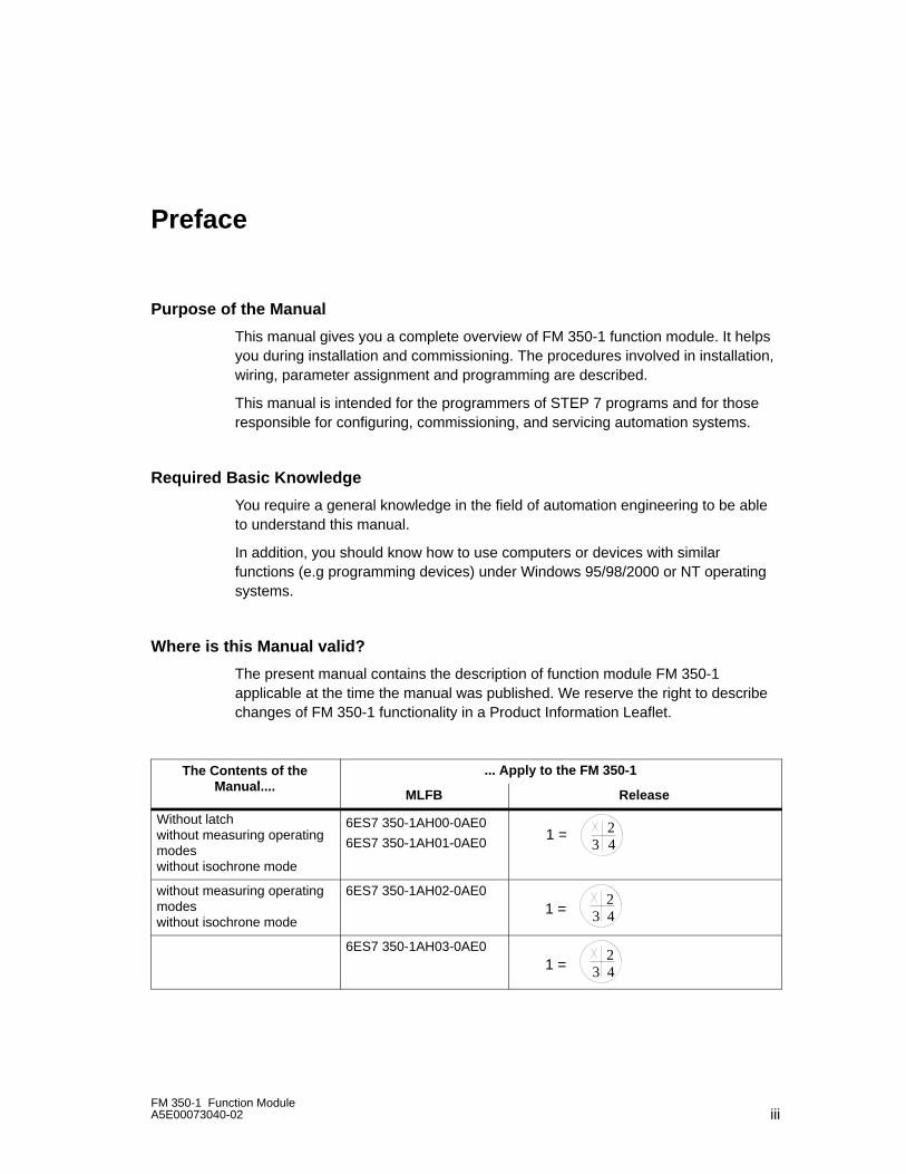
The present manual contains the description of function module FM 350-1applicable at the time the manual was published. We reserve the right to describechanges of FM 350-1 functionality in a Product Information Leaflet.
The Contents of theMan al
... Apply to the FM 350-1Manual....
MLFB Release
Without latch without measuring operatingmodeswithout isochrone mode
6ES7 350-1AH00-0AE0
6ES7 350-1AH01-0AE0 4321 =
without measuring operatingmodeswithout isochrone mode
6ES7 350-1AH02-0AE0
432
1 =
6ES7 350-1AH03-0AE0
432
1 =
Preface
ivFM 350-1 Function Module
A5E00073040-02
Changes compared to the previous version
FM 350-1 features the following enhancements:
• Frequency measurement
• Rotation speed measurement
• Period measurement
• Isochrone mode in a modular slave (ET 200M)
• System modification during operation using CiR /3/
• More latch edges
• Hysteresis for counting modes
• Firmware update
Certification
• Underwriters Laboratories, Inc.: UL 508 registered (Industrial Control Equipment)
• Canadian Standards Association: CSA C22.2 number 142, (Process Control Equipment)
• Factory Mutual Research: Approval Standard Class Number 3611.
CE Labeling
SIMATIC S7-300 products fulfil the requirements and protection guidelines of thefollowing EU directives:
• EC Directive 73/23/EEC “Low-voltage directive”
• EC Directive 89/336/EWG “EMC directive”
CTick Mark
SIMATIC products S7-300 are compliant with requirements of the AS/NZS 2064 (Australian) standard.
Standards
SIMATIC S7-300 products fulfil the requirements and criteria of IEC 61131-2.
Place of this Documentation in the Information Environment
This manual is acomponent of the documentation package 6ES7350-1AH00-8BG0.
Preface
vFM 350-1 Function ModuleA5E00073040-02
Recycling and Disposal
FM 350-1 is recycleable due to its non-toxic materials. Please contact a companycertified in the disposal of electronic scrap for environmentally safe recycling anddisposal of your old device.
Further Support
If you have any technical questions, please get in touch with your Siemensrepresentative or agent responsible.
http://www.siemens.com/automation/partner
Training Centers
Siemens offers a number of training courses to familiarize you with the SIMATIC S7automation system. Please contact your regional training center or our centraltraining center in D 90327 Nuremberg, Germany for details:
Telephone: +49 (911) 895-3200.
Internet: http://www.sitrain.com
Preface
viFM 350-1 Function Module
A5E00073040-02
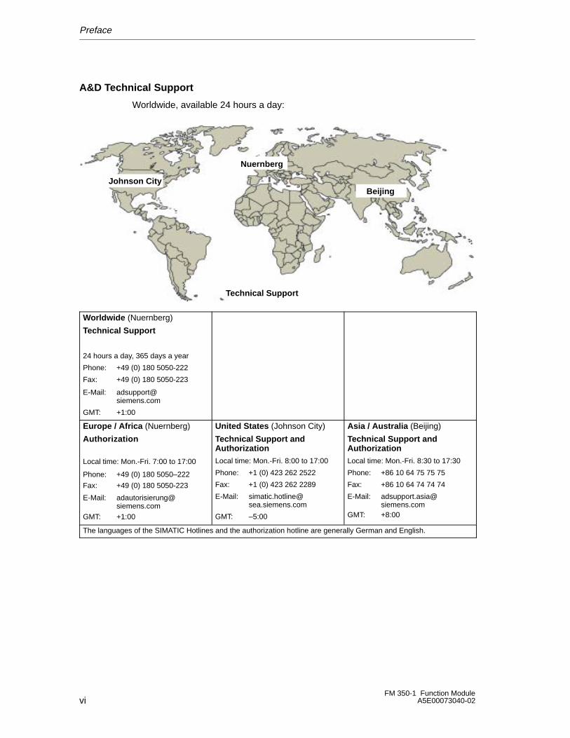
A&D Technical Support
Worldwide, available 24 hours a day:
Johnson City
Nuernberg
Beijing
Technical Support
Worldwide (Nuernberg)
Technical Support
24 hours a day, 365 days a year
Phone: +49 (0) 180 5050-222
Fax: +49 (0) 180 5050-223
E-Mail: [email protected]
GMT: +1:00
Europe / Africa (Nuernberg)
Authorization
Local time: Mon.-Fri. 7:00 to 17:00
Phone: +49 (0) 180 5050–222
Fax: +49 (0) 180 5050-223
E-Mail: [email protected]
GMT: +1:00
United States (Johnson City)
Technical Support andAuthorizationLocal time: Mon.-Fri. 8:00 to 17:00
Phone: +1 (0) 423 262 2522
Fax: +1 (0) 423 262 2289
E-Mail: [email protected]
GMT: –5:00
Asia / Australia (Beijing)
Technical Support andAuthorizationLocal time: Mon.-Fri. 8:30 to 17:30
Phone: +86 10 64 75 75 75
Fax: +86 10 64 74 74 74
E-Mail: [email protected]
GMT: +8:00
The languages of the SIMATIC Hotlines and the authorization hotline are generally German and English.
Preface
viiFM 350-1 Function ModuleA5E00073040-02
Service & Support on the Internet
In addition to our documentation, we offer our Know-how online on the internet at:
http://www.siemens.com/automation/service&support
where you will find the following:
• The newsletter, which constantly provides you with up-to-date information onyour products.
• The right documents via our Search function in Service & Support.
• A forum, where users and experts from all over the world exchange theirexperiences.
• Your local representative for Automation & Drives via our representativesdatabase.
• Information on field service, repairs, spare parts and more under “Services”.

Preface
viiiFM 350-1 Function Module
A5E00073040-02
ixFM 350-1 Function ModuleA5E00073040-02
Contents
1 Product Overview 1-1. . . . . . . . . . . . . . . . . . . . . . . . . . . . . . . . . . . . . . . . . . . . . . . . . . . . . . .
1.1 What Can the FM 350-1 Do? 1-2. . . . . . . . . . . . . . . . . . . . . . . . . . . . . . . . . . . . . .
1.2 Application Areas of the FM 350-1 1-5. . . . . . . . . . . . . . . . . . . . . . . . . . . . . . . . . .
1.3 FM 350-1 Hardware 1-7. . . . . . . . . . . . . . . . . . . . . . . . . . . . . . . . . . . . . . . . . . . . . .
1.4 FM 350-1 Software 1-10. . . . . . . . . . . . . . . . . . . . . . . . . . . . . . . . . . . . . . . . . . . . . . .
2 Installing and Removing the FM 350-1 2-1. . . . . . . . . . . . . . . . . . . . . . . . . . . . . . . . . . . .
2.1 Preparing the Installation 2-2. . . . . . . . . . . . . . . . . . . . . . . . . . . . . . . . . . . . . . . . . .
2.2 Installing and Removing the FM 350-1 2-3. . . . . . . . . . . . . . . . . . . . . . . . . . . . . .
3 Wiring the FM 350-1 3-1. . . . . . . . . . . . . . . . . . . . . . . . . . . . . . . . . . . . . . . . . . . . . . . . . . . . .
3.1 Terminal Assignments of the Front Connector 3-2. . . . . . . . . . . . . . . . . . . . . . . .
3.2 Wiring the Front Connector 3-7. . . . . . . . . . . . . . . . . . . . . . . . . . . . . . . . . . . . . . . .
3.3 Module Status After Switching On 3-10. . . . . . . . . . . . . . . . . . . . . . . . . . . . . . . . . .
4 Assigning Parameters to the FM 350-1 4-1. . . . . . . . . . . . . . . . . . . . . . . . . . . . . . . . . . . .
4.1 Installing and Calling Parameter Assignment Screen Forms 4-2. . . . . . . . . . .
5 Programming the FM 350-1 5-1. . . . . . . . . . . . . . . . . . . . . . . . . . . . . . . . . . . . . . . . . . . . . . .
5.1 The CNT_CTL1 Function (FC 2) 5-3. . . . . . . . . . . . . . . . . . . . . . . . . . . . . . . . . . .
5.2 The CNT_CTL2 Function (FC 3) 5-10. . . . . . . . . . . . . . . . . . . . . . . . . . . . . . . . . . .
5.3 The DIAG_INF Function (FC 1) 5-11. . . . . . . . . . . . . . . . . . . . . . . . . . . . . . . . . . . .
5.4 Application Example 5-12. . . . . . . . . . . . . . . . . . . . . . . . . . . . . . . . . . . . . . . . . . . . . .
5.5 Technical Data for the Blocks 5-15. . . . . . . . . . . . . . . . . . . . . . . . . . . . . . . . . . . . . .
5.6 Programming the FM 350-1 without FCs 5-16. . . . . . . . . . . . . . . . . . . . . . . . . . . . 5.6.1 Control and Check-back Interface for the Count Modes 5-16. . . . . . . . . . . . . . . 5.6.2 Control and Check-back Interface for the Measure Modes 5-24. . . . . . . . . . . . . 5.6.3 Using the Interface with the Complete Acknowledgement Principle 5-31. . . . . 5.6.4 Restart Coordination 5-35. . . . . . . . . . . . . . . . . . . . . . . . . . . . . . . . . . . . . . . . . . . . .
5.7 Reaction to CPU STOP and CPU STOP-RUN 5-36. . . . . . . . . . . . . . . . . . . . . . .
Contents
xFM 350-1 Function Module
A5E00073040-02
6 Programming in M7 with the Counter Function Library 6-1. . . . . . . . . . . . . . . . . . . . .
6.1 Overview 6-2. . . . . . . . . . . . . . . . . . . . . . . . . . . . . . . . . . . . . . . . . . . . . . . . . . . . . . .
6.2 Basic Program Structure 6-4. . . . . . . . . . . . . . . . . . . . . . . . . . . . . . . . . . . . . . . . . .
6.3 Initializing and Parameterizing the Counter Channel 6-5. . . . . . . . . . . . . . . . . .
6.4 Transferring the Load Value and Comparison Values 6-8. . . . . . . . . . . . . . . . .
6.5 Control of the Digital Inputs and Outputs 6-9. . . . . . . . . . . . . . . . . . . . . . . . . . . .
6.6 Starting and Stopping the Counter Channel 6-10. . . . . . . . . . . . . . . . . . . . . . . . .
6.7 Reading the Counter Value and the Load Value, Scanning and Resetting the Status 6-12. . . . . . . . . . . . . . . . . . . . . . . . . . . . . . . . .
6.8 Processing Interrupts 6-13. . . . . . . . . . . . . . . . . . . . . . . . . . . . . . . . . . . . . . . . . . . . .
6.9 Processing Error Messages 6-14. . . . . . . . . . . . . . . . . . . . . . . . . . . . . . . . . . . . . . .
7 Starting Up the FM 350-1 7-1. . . . . . . . . . . . . . . . . . . . . . . . . . . . . . . . . . . . . . . . . . . . . . . . .
7.1 Mechanical Installation Checklist 7-2. . . . . . . . . . . . . . . . . . . . . . . . . . . . . . . . . . .
7.2 Parameter Assignment Checklist 7-4. . . . . . . . . . . . . . . . . . . . . . . . . . . . . . . . . . .
8 Operating Modes, Parameters and Commands 8-1. . . . . . . . . . . . . . . . . . . . . . . . . . . .
8.1 Basic Information on Calling Operating Modes, Settings and Commands 8-2
8.2 Isochrone Mode 8-3. . . . . . . . . . . . . . . . . . . . . . . . . . . . . . . . . . . . . . . . . . . . . . . . .
8.3 Count Modes 8-4. . . . . . . . . . . . . . . . . . . . . . . . . . . . . . . . . . . . . . . . . . . . . . . . . . . . 8.3.1 What are the Count Modes? 8-4. . . . . . . . . . . . . . . . . . . . . . . . . . . . . . . . . . . . . . . 8.3.2 Definitions 8-5. . . . . . . . . . . . . . . . . . . . . . . . . . . . . . . . . . . . . . . . . . . . . . . . . . . . . . 8.3.3 Continuous Counting 8-8. . . . . . . . . . . . . . . . . . . . . . . . . . . . . . . . . . . . . . . . . . . . . 8.3.4 Single Counting 8-10. . . . . . . . . . . . . . . . . . . . . . . . . . . . . . . . . . . . . . . . . . . . . . . . . . 8.3.5 Periodic Counting 8-15. . . . . . . . . . . . . . . . . . . . . . . . . . . . . . . . . . . . . . . . . . . . . . . . 8.3.6 Count Range 8-20. . . . . . . . . . . . . . . . . . . . . . . . . . . . . . . . . . . . . . . . . . . . . . . . . . . . 8.3.7 Command: Open and Close Gate 8-21. . . . . . . . . . . . . . . . . . . . . . . . . . . . . . . . . . 8.3.8 Behavior of the Digital Outputs 8-27. . . . . . . . . . . . . . . . . . . . . . . . . . . . . . . . . . . . . 8.3.9 Command: Set Counter 8-38. . . . . . . . . . . . . . . . . . . . . . . . . . . . . . . . . . . . . . . . . . . 8.3.10 Command: Latch/Retrigger 8-44. . . . . . . . . . . . . . . . . . . . . . . . . . . . . . . . . . . . . . . . 8.3.11 Command: Latch 8-46. . . . . . . . . . . . . . . . . . . . . . . . . . . . . . . . . . . . . . . . . . . . . . . . . 8.3.12 Command: Measure the Times Between two Edges 8-48. . . . . . . . . . . . . . . . . .
8.4 Measure Modes 8-49. . . . . . . . . . . . . . . . . . . . . . . . . . . . . . . . . . . . . . . . . . . . . . . . . 8.4.1 What are the Measure Modes? 8-49. . . . . . . . . . . . . . . . . . . . . . . . . . . . . . . . . . . . 8.4.2 Definitions 8-50. . . . . . . . . . . . . . . . . . . . . . . . . . . . . . . . . . . . . . . . . . . . . . . . . . . . . . 8.4.3 Frequency Measurement 8-55. . . . . . . . . . . . . . . . . . . . . . . . . . . . . . . . . . . . . . . . . . 8.4.4 RPM Measurement 8-57. . . . . . . . . . . . . . . . . . . . . . . . . . . . . . . . . . . . . . . . . . . . . . . 8.4.5 Continuous Periodic Measurement 8-59. . . . . . . . . . . . . . . . . . . . . . . . . . . . . . . . . 8.4.6 Command: Open and Close Gate 8-62. . . . . . . . . . . . . . . . . . . . . . . . . . . . . . . . . . 8.4.7 Behavior of the Digital Outputs 8-66. . . . . . . . . . . . . . . . . . . . . . . . . . . . . . . . . . . . .
8.5 Initiating a Process Interrupt 8-69. . . . . . . . . . . . . . . . . . . . . . . . . . . . . . . . . . . . . . .
Contents
xiFM 350-1 Function ModuleA5E00073040-02
9 Encoder Signals and Their Evaluation 9-1. . . . . . . . . . . . . . . . . . . . . . . . . . . . . . . . . . . .
9.1 Overview 9-2. . . . . . . . . . . . . . . . . . . . . . . . . . . . . . . . . . . . . . . . . . . . . . . . . . . . . . .
9.2 5 V Differential Signals 9-3. . . . . . . . . . . . . . . . . . . . . . . . . . . . . . . . . . . . . . . . . . . .
9.3 24 V Signals 9-5. . . . . . . . . . . . . . . . . . . . . . . . . . . . . . . . . . . . . . . . . . . . . . . . . . . . .
9.4 Pulse Evaluation 9-7. . . . . . . . . . . . . . . . . . . . . . . . . . . . . . . . . . . . . . . . . . . . . . . . .
10 DB Assignments 10-1. . . . . . . . . . . . . . . . . . . . . . . . . . . . . . . . . . . . . . . . . . . . . . . . . . . . . . . .
11 M7 Reference Counter Function Library 11-1. . . . . . . . . . . . . . . . . . . . . . . . . . . . . . . . . . .
11.1 M7CntDisableOut 11-2. . . . . . . . . . . . . . . . . . . . . . . . . . . . . . . . . . . . . . . . . . . . . . . .
11.2 M7CntDisableSet 11-3. . . . . . . . . . . . . . . . . . . . . . . . . . . . . . . . . . . . . . . . . . . . . . . .
11.3 M7CntEnableOut 11-4. . . . . . . . . . . . . . . . . . . . . . . . . . . . . . . . . . . . . . . . . . . . . . . .
11.4 M7CntEnableSet 11-5. . . . . . . . . . . . . . . . . . . . . . . . . . . . . . . . . . . . . . . . . . . . . . . . .
11.5 M7CntInit 11-7. . . . . . . . . . . . . . . . . . . . . . . . . . . . . . . . . . . . . . . . . . . . . . . . . . . . . . .
11.6 M7CntLoadAndStart 11-9. . . . . . . . . . . . . . . . . . . . . . . . . . . . . . . . . . . . . . . . . . . . . .
11.7 M7CntLoadComp 11-11. . . . . . . . . . . . . . . . . . . . . . . . . . . . . . . . . . . . . . . . . . . . . . . .
11.8 M7CntLoadDirect 11-13. . . . . . . . . . . . . . . . . . . . . . . . . . . . . . . . . . . . . . . . . . . . . . . .
11.9 M7CntLoadPrep 11-15. . . . . . . . . . . . . . . . . . . . . . . . . . . . . . . . . . . . . . . . . . . . . . . . .
11.10 M7CntPar 11-17. . . . . . . . . . . . . . . . . . . . . . . . . . . . . . . . . . . . . . . . . . . . . . . . . . . . . . .
11.11 M7CntRead 11-19. . . . . . . . . . . . . . . . . . . . . . . . . . . . . . . . . . . . . . . . . . . . . . . . . . . . .
11.12 M7CntReadDiag 11-21. . . . . . . . . . . . . . . . . . . . . . . . . . . . . . . . . . . . . . . . . . . . . . . . .
11.13 M7CntReadLoadValue 11-22. . . . . . . . . . . . . . . . . . . . . . . . . . . . . . . . . . . . . . . . . . . .
11.14 M7CntReadParError 11-23. . . . . . . . . . . . . . . . . . . . . . . . . . . . . . . . . . . . . . . . . . . . . .
11.15 M7CntReadStatus 11-24. . . . . . . . . . . . . . . . . . . . . . . . . . . . . . . . . . . . . . . . . . . . . . .
11.16 M7CntResetStatus 11-26. . . . . . . . . . . . . . . . . . . . . . . . . . . . . . . . . . . . . . . . . . . . . . .
11.17 M7CntStart 11-27. . . . . . . . . . . . . . . . . . . . . . . . . . . . . . . . . . . . . . . . . . . . . . . . . . . . . .
11.18 M7CntStop 11-28. . . . . . . . . . . . . . . . . . . . . . . . . . . . . . . . . . . . . . . . . . . . . . . . . . . . . .
11.19 M7CntStopAndRead 11-30. . . . . . . . . . . . . . . . . . . . . . . . . . . . . . . . . . . . . . . . . . . . .
11.20 M7CNT_DIAGINFO 11-31. . . . . . . . . . . . . . . . . . . . . . . . . . . . . . . . . . . . . . . . . . . . . .
11.21 M7CNT_PARAM 11-33. . . . . . . . . . . . . . . . . . . . . . . . . . . . . . . . . . . . . . . . . . . . . . . . .
11.22 M7CNT_STATUS 11-36. . . . . . . . . . . . . . . . . . . . . . . . . . . . . . . . . . . . . . . . . . . . . . . .
11.23 Error Codes 11-37. . . . . . . . . . . . . . . . . . . . . . . . . . . . . . . . . . . . . . . . . . . . . . . . . . . . .
Contents
xiiFM 350-1 Function Module
A5E00073040-02
12 Faults and Diagnostics 12-1. . . . . . . . . . . . . . . . . . . . . . . . . . . . . . . . . . . . . . . . . . . . . . . . . .
12.1 Fault Indication via the Group Error LED 12-2. . . . . . . . . . . . . . . . . . . . . . . . . . . .
12.2 Initiation of Diagnostics Interrupts 12-3. . . . . . . . . . . . . . . . . . . . . . . . . . . . . . . . . .
12.3 Data Errors 12-7. . . . . . . . . . . . . . . . . . . . . . . . . . . . . . . . . . . . . . . . . . . . . . . . . . . . . .
12.4 Operator Errors 12-9. . . . . . . . . . . . . . . . . . . . . . . . . . . . . . . . . . . . . . . . . . . . . . . . . .
A Technical Specifications A-1. . . . . . . . . . . . . . . . . . . . . . . . . . . . . . . . . . . . . . . . . . . . . . . . .
B Spare Parts B-1. . . . . . . . . . . . . . . . . . . . . . . . . . . . . . . . . . . . . . . . . . . . . . . . . . . . . . . . . . . . .
C References C-1. . . . . . . . . . . . . . . . . . . . . . . . . . . . . . . . . . . . . . . . . . . . . . . . . . . . . . . . . . . . . .
Glossary Glossary-1. . . . . . . . . . . . . . . . . . . . . . . . . . . . . . . . . . . . . . . . . . . . . . . . . . . . . . . . . .
Index Index-1. . . . . . . . . . . . . . . . . . . . . . . . . . . . . . . . . . . . . . . . . . . . . . . . . . . . . . . . . . . . . . . . .
Contents
xiiiFM 350-1 Function ModuleA5E00073040-02
Figures1-1 Example for Using an FM 350-1 in the S7-300 1-6. . . . . . . . . . . . . . . . . . . . . . . 1-2 FM 350-1 Module View 1-7. . . . . . . . . . . . . . . . . . . . . . . . . . . . . . . . . . . . . . . . . . . 1-3 SIMATIC S7-300 configuration with an FM 350-1 1-10. . . . . . . . . . . . . . . . . . . . . 2-1 Installing the Coding Connector 2-4. . . . . . . . . . . . . . . . . . . . . . . . . . . . . . . . . . . . 3-1 Front Connector of the FM 350-1 3-2. . . . . . . . . . . . . . . . . . . . . . . . . . . . . . . . . . . 3-2 Details Regarding the Connection of an Incremental 5V Encoder 3-7. . . . . . . 3-3 Details Regarding the Connection of an Incremental 24V Encoder 3-8. . . . . . 3-4 FM 350-1 with Shielded Cables and the Shield Support 3-9. . . . . . . . . . . . . . . 5-1 Exchange of Data between the User Program and FM 350-1 with FC‘s 5-2. . 5-2 Complete acknowledgement principle 5-31. . . . . . . . . . . . . . . . . . . . . . . . . . . . . . . 5-3 Transfer of values 5-32. . . . . . . . . . . . . . . . . . . . . . . . . . . . . . . . . . . . . . . . . . . . . . . . 5-4 Resetting the status bits 5-34. . . . . . . . . . . . . . . . . . . . . . . . . . . . . . . . . . . . . . . . . . 5-5 Restart sequence 5-35. . . . . . . . . . . . . . . . . . . . . . . . . . . . . . . . . . . . . . . . . . . . . . . . 8-1 Continuous counting with gate control 8-8. . . . . . . . . . . . . . . . . . . . . . . . . . . . . . 8-2 Single counting without main counting direction; Cancel gate function 8-10. . . 8-3 Single counting without main counting direction; Cancel gate function 8-11. . . 8-4 Single counting with main counting direction down;
Cancel gate function 8-12. . . . . . . . . . . . . . . . . . . . . . . . . . . . . . . . . . . . . . . . . . . . . . 8-5 Single Counting with Load Value and gate control 8-13. . . . . . . . . . . . . . . . . . . . 8-6 Periodic counting without main counting direction 8-15. . . . . . . . . . . . . . . . . . . . 8-7 Periodic counting with main counting direction up 8-16. . . . . . . . . . . . . . . . . . . . 8-8 Periodic counting with main counting direction down 8-17. . . . . . . . . . . . . . . . . . 8-9 Periodic Counting with Load Value and gate control 8-18. . . . . . . . . . . . . . . . . . 8-10 Level-Controlled Opening and Closing of the Hardware Gate 8-21. . . . . . . . . . 8-11 Edge-Controlled Opening and Closing of the Hardware Gate 8-22. . . . . . . . . . 8-12 Opening and Closing of the Software Gate 8-23. . . . . . . . . . . . . . . . . . . . . . . . . . 8-13 Continuous counting, down, Cancel gate function 8-24. . . . . . . . . . . . . . . . . . . . 8-14 Continuous counting, down, Interrupt gate function 8-24. . . . . . . . . . . . . . . . . . . 8-15 Starting and stopping the counting operation
with the SW gate (SW_GATE) 8-25. . . . . . . . . . . . . . . . . . . . . . . . . . . . . . . . . . . . . 8-16 Starting and stopping the counting process
with the HW gate (HW_GATE) 8-25. . . . . . . . . . . . . . . . . . . . . . . . . . . . . . . . . . . . . 8-17 At the start of the counting process, V2 > V1 8-31. . . . . . . . . . . . . . . . . . . . . . . . . 8-18 At the start of the counting process, V1 > V2 8-32. . . . . . . . . . . . . . . . . . . . . . . . . 8-19 Reactions of an output for a pulse duration 0 ms 8-33. . . . . . . . . . . . . . . . . . . . . 8-20 Example showing the effect of hysteresis 8-36. . . . . . . . . . . . . . . . . . . . . . . . . . . . 8-21 Example in response to a change of direction at the comparison value 8-36. . 8-22 Example showing the effect of hysteresis 8-37. . . . . . . . . . . . . . . . . . . . . . . . . . . . 8-23 Single Setting with DI Set 8-40. . . . . . . . . . . . . . . . . . . . . . . . . . . . . . . . . . . . . . . . . 8-24 Multiple Setting with DI Set 8-41. . . . . . . . . . . . . . . . . . . . . . . . . . . . . . . . . . . . . . . . 8-25 Single Setting of the Counter with the Zero Mark 8-42. . . . . . . . . . . . . . . . . . . . . 8-26 Multiple Setting of the Counter with the Zero Mark 8-43. . . . . . . . . . . . . . . . . . . . 8-27 Latch/Retrigger when load value = 0 and a positive edge at Start DI 8-45. . . . 8-28 Latch when load value = 0 and a positive edge at Start DI 8-47. . . . . . . . . . . . . 8-29 Measuring principle 8-50. . . . . . . . . . . . . . . . . . . . . . . . . . . . . . . . . . . . . . . . . . . . . . 8-30 Principle of continuous measurement
(example of a frequency measurement) 8-52. . . . . . . . . . . . . . . . . . . . . . . . . . . . . 8-31 Limit value monitoring in Measure modes 8-53. . . . . . . . . . . . . . . . . . . . . . . . . . . 8-32 Frequency measurement with gate function 8-55. . . . . . . . . . . . . . . . . . . . . . . . . 8-33 RPM measurement with gate function 8-57. . . . . . . . . . . . . . . . . . . . . . . . . . . . . . 8-34 Periodic measurement of the gate function 8-59. . . . . . . . . . . . . . . . . . . . . . . . . .
Contents
xivFM 350-1 Function Module
A5E00073040-02
8-35 Level-controlled opening and closing of the HW gate 8-62. . . . . . . . . . . . . . . . . 8-36 Edge-controlled opening and closing of the HW gate 8-63. . . . . . . . . . . . . . . . . 8-37 Level-controlled opening and closing of the SW gate 8-64. . . . . . . . . . . . . . . . . 8-38 Starting and stopping the counting process
with the SW gate (SW_GATE) 8-65. . . . . . . . . . . . . . . . . . . . . . . . . . . . . . . . . . . . . 8-39 Starting and stopping the counting process
with the HW gate (HW_GATE) 8-65. . . . . . . . . . . . . . . . . . . . . . . . . . . . . . . . . . . . . 9-1 Signals of the Incremental 5 V encoder 9-3. . . . . . . . . . . . . . . . . . . . . . . . . . . . . 9-2 Signals of a 24 V Pulse Encoder with Direction Level 9-5. . . . . . . . . . . . . . . . . 9-3 Single Evaluation 9-7. . . . . . . . . . . . . . . . . . . . . . . . . . . . . . . . . . . . . . . . . . . . . . . . 9-4 Double Evaluation 9-8. . . . . . . . . . . . . . . . . . . . . . . . . . . . . . . . . . . . . . . . . . . . . . . . 9-5 Quadruple Evaluation 9-8. . . . . . . . . . . . . . . . . . . . . . . . . . . . . . . . . . . . . . . . . . . . .
Contents
xvFM 350-1 Function ModuleA5E00073040-02
Tables1-1 Input Filters 1-3. . . . . . . . . . . . . . . . . . . . . . . . . . . . . . . . . . . . . . . . . . . . . . . . . . . . . 3-1 Front Connector Assignments 3-3. . . . . . . . . . . . . . . . . . . . . . . . . . . . . . . . . . . . . 3-2 Input Filters for 24 V Encoder Signals 3-5. . . . . . . . . . . . . . . . . . . . . . . . . . . . . . . 3-3 Input Filters for Digital Inputs 3-6. . . . . . . . . . . . . . . . . . . . . . . . . . . . . . . . . . . . . . 5-1 Parameters for transferring values in the DB (Count modes) 5-8. . . . . . . . . . 5-2 Parameters for transferring values in the DB (Measure modes) 5-9. . . . . . . . 5-3 DIAG_INF function parameters 5-11. . . . . . . . . . . . . . . . . . . . . . . . . . . . . . . . . . . . 5-4 Symbols in Example 5-13. . . . . . . . . . . . . . . . . . . . . . . . . . . . . . . . . . . . . . . . . . . . . 5-5 Control interface for Count modes (outputs) 5-17. . . . . . . . . . . . . . . . . . . . . . . . . 5-6 Explanation of the control bits for the Count modes 5-19. . . . . . . . . . . . . . . . . . 5-7 Check-back interface for Count modes (inputs) 5-20. . . . . . . . . . . . . . . . . . . . . . 5-8 Explanation of the check-back bits for the Count modes 5-22. . . . . . . . . . . . . . 5-9 Control interface for Measure modes (outputs) 5-24. . . . . . . . . . . . . . . . . . . . . . 5-10 Explanation of the control bits for the Measure modes 5-26. . . . . . . . . . . . . . . . 5-11 Check-back interface for Measure modes (inputs) 5-27. . . . . . . . . . . . . . . . . . . 5-12 Explanation of the check-back bits for the Measure modes 5-29. . . . . . . . . . . . 5-13 Data record DS 2 5-34. . . . . . . . . . . . . . . . . . . . . . . . . . . . . . . . . . . . . . . . . . . . . . . . 8-1 The FM 350-1 Count modes 8-4. . . . . . . . . . . . . . . . . . . . . . . . . . . . . . . . . . . . . . 8-2 Starting count 8-6. . . . . . . . . . . . . . . . . . . . . . . . . . . . . . . . . . . . . . . . . . . . . . . . . . . 8-3 The FM 350-1 commands 8-7. . . . . . . . . . . . . . . . . . . . . . . . . . . . . . . . . . . . . . . . 8-4 Output DO0 8-30. . . . . . . . . . . . . . . . . . . . . . . . . . . . . . . . . . . . . . . . . . . . . . . . . . . . . 8-5 Output DO1 8-30. . . . . . . . . . . . . . . . . . . . . . . . . . . . . . . . . . . . . . . . . . . . . . . . . . . . . 8-6 Marginal conditions for the behavior of the digital outputs 8-34. . . . . . . . . . . . . 8-7 Effect of the hysteresis 8-35. . . . . . . . . . . . . . . . . . . . . . . . . . . . . . . . . . . . . . . . . . . 8-8 The FM 350-1 Measure modes 8-49. . . . . . . . . . . . . . . . . . . . . . . . . . . . . . . . . . . . 8-9 Starting count 8-53. . . . . . . . . . . . . . . . . . . . . . . . . . . . . . . . . . . . . . . . . . . . . . . . . . . 8-10 The FM 350-1 commands 8-54. . . . . . . . . . . . . . . . . . . . . . . . . . . . . . . . . . . . . . . . 8-11 Calculating the update time 8-55. . . . . . . . . . . . . . . . . . . . . . . . . . . . . . . . . . . . . . . 8-12 Calculating the update time 8-57. . . . . . . . . . . . . . . . . . . . . . . . . . . . . . . . . . . . . . . 8-13 Calculating the update time 8-59. . . . . . . . . . . . . . . . . . . . . . . . . . . . . . . . . . . . . . . 8-14 Behavior of digital output DO0 8-67. . . . . . . . . . . . . . . . . . . . . . . . . . . . . . . . . . . . . 8-15 Output DO0 8-68. . . . . . . . . . . . . . . . . . . . . . . . . . . . . . . . . . . . . . . . . . . . . . . . . . . . . 8-16 Output DO1 8-68. . . . . . . . . . . . . . . . . . . . . . . . . . . . . . . . . . . . . . . . . . . . . . . . . . . . . 8-17 Assignment of the bits of the variable OB40_POINT_ADDR 8-70. . . . . . . . . . . 9-1 Encoders for the FM 350-1 9-2. . . . . . . . . . . . . . . . . . . . . . . . . . . . . . . . . . . . . . . . 9-2 Count Direction in Dependence on the Input Parameterization 9-6. . . . . . . . . 9-3 Input Filters 9-6. . . . . . . . . . . . . . . . . . . . . . . . . . . . . . . . . . . . . . . . . . . . . . . . . . . . . 10-1 DB Assignments 10-1. . . . . . . . . . . . . . . . . . . . . . . . . . . . . . . . . . . . . . . . . . . . . . . . 11-1 Detailed Specifications of the Parameterization Data 11-34. . . . . . . . . . . . . . . . . 11-2 Operator Errors 11-37. . . . . . . . . . . . . . . . . . . . . . . . . . . . . . . . . . . . . . . . . . . . . . . . . 11-3 Counter Function Errors 11-38. . . . . . . . . . . . . . . . . . . . . . . . . . . . . . . . . . . . . . . . . . 11-4 Parameterization Errors 11-39. . . . . . . . . . . . . . . . . . . . . . . . . . . . . . . . . . . . . . . . . . . 12-1 Assignments of Diagnostics Data Set DS0 12-4. . . . . . . . . . . . . . . . . . . . . . . . . . 12-2 Assignments of the Bits of Bytes 4 to 11 of Diagnostics Data Set 12-5. . . . . . . 12-3 Data Error Numbers and their Meanings 12-7. . . . . . . . . . . . . . . . . . . . . . . . . . . . 12-4 Numbers of the Operator Errors and their Meaning 12-9. . . . . . . . . . . . . . . . . . . B-1 Accessories and Spare Parts B-1. . . . . . . . . . . . . . . . . . . . . . . . . . . . . . . . . . . . .

Contents
xviFM 350-1 Function Module
A5E00073040-02
1-1FM 350-1 Function ModuleA5E00073040-02
Product Overview
Chapter Overview
This chapter gives you an overview of the FM 350-1 function module.
• You will learn what the FM 350-1 can do.
• You will become familiar with the application areas of the FM 350-1 throughexamples.
• You will learn how the FM 350-1 is linked into the S7-300/M7-300programmable controller and you will become familiar with the most importantcomponents of the FM 350-1.
Section Description Page
1.1 What Can the FM 350-1 Do? 1-2
1.2 Application Areas of the FM 350-1 1-5
1.3 FM 350-1 Hardware 1-7
1.4 FM 350-1 Software 1-10
1
Product Overview
1-2FM 350-1 Function Module
A5E00073040-02
1.1 What Can the FM 350-1 Do?
What Can the FM 350-1 Do?
The FM 350-1 function module is a high-speed counter module for use in theS7-300/M7-300 programmable controller. There is one counter on the module thatcan operate in the following ranges:
• 0 to 4,294,967,295 (0 to 232 – 1) or
• – 2,147,483,648 to + 2,147,483,647 (–231 to 231 – 1).
The maximum input frequency of the counter signals is up to 500 kHz dependingon the encoder signal.
You can use the FM 350-1 for the following tasks:
• Continuous counting
• Single counting
• Periodic counting
• Frequency measurement
• Rotational speed measurement
• Period measurement
You can start and stop each mode either via the user program (software gate) orvia external signals (hardware gate).
Comparison Values
You can store two comparison values on the module assigned to the two relevantoutputs on the module. If the counter status reaches one of the two comparisonvalues, the relevant output can be set to initiate control actions direct in theprocess.
Load Value
You can specify a value on the FM 350-1 from which it should begin counting. Thisvalue is called the load value. Any value within the count limits can be set for theload value.
Process Interrupts
The FM 350-1 can trigger a process interrupt in the CPU if the comparison valuesare reached, or in the case of overflow, underflow and/or in the case of zero passof a counter.
Product Overview
1-3FM 350-1 Function ModuleA5E00073040-02
Diagnostics Interrupts
The FM 350-1 can trigger a diagnostics interrupt if any of the following occur:
• Fault in external auxiliary voltage
• Fault in 5.2 VDC encoder supply
• Module not parameterized or errors in parameterization
• Watchdog triggered
• RAM defective
• Process interrupt lost
• Fault in signal A, B or N
Pulse Duration
You can specify a pulse duration for the digital outputs of the FM 350-1. The pulseduration specifies how long the relevant digital output is to be set. You can specifya value between 0 and 500 ms for the pulse duration. This value applies for bothoutputs. You can adapt the FM 350-1 to existing actuators by specifying a pulseduration.
Which Signals can the FM 350-1 Register?
The FM 350-1 can register the signals from the following sources:
• Incremental 5 V encoders
• Incremental 24 V encoders
• 24 V pulse encoders with direction level
• 24 V initiators without direction level for example, light barrier or BERO
• Internal 1 MHz time base
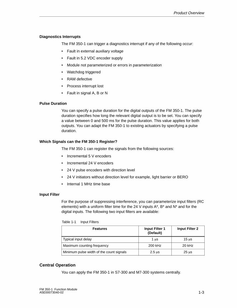
Input Filter
For the purpose of suppressing interference, you can parameterize input filters (RCelements) with a uniform filter time for the 24 V inputs A*, B* and N* and for thedigital inputs. The following two input filters are available:
Table 1-1 Input Filters
Features Input Filter 1(Default)
Input Filter 2
Typical input delay 1 �s 15 �s
Maximum counting frequency 200 kHz 20 kHz
Minimum pulse width of the count signals 2.5 �s 25 �s
Central Operation
You can apply the FM 350-1 in S7-300 and M7-300 systems centrally.
Product Overview
1-4FM 350-1 Function Module
A5E00073040-02
Distributed Operation
You can use the FM 350-1 via IM 153-1, IM 153-2 and IM 153-3 distributed inET 200M. Examples of application are:
• ET 200M with single backplane bus
• ET 200M with active backplane bus
• ET 200M as moduled clocked mode slave
• ET 200M in one-sided mode in an H system
• ET 200M in interconnected mode in an H system
Firmware Update
For upgrades and bugfixes it is possible with the help of STEP 7 HW Config (as ofV 5.2) to download firmware updates to the operating system memory of FM 350-1.
Notice
Starting the firmware updates deletes the old FM 350-1 firmware.
If the firmware update is interupted or terminated by any means, the FM 350-1 willno longer be available.
Please start the firmware update again and wait until it is successfully completed.
CiR
The FM 350-1 is CiR-compatible, i. e. via configuration modification at RUN of theCPU you can change the FM 350-1parameters. Parameter changes resets theFM 350-1 and is essentially a reconfiguration.
FM 350-1 allows parameter changes during operation of the user program (seechapter 4).
Isochrone Mode
Depending on your STEP 7 V 5.2 configuration, you can work with the FM 350-1either in non-isochrone or isochrone mode.
Product Overview
1-5FM 350-1 Function ModuleA5E00073040-02
1.2 Application Areas of the FM 350-1
Where Can You Use the FM 350-1?
The main application area of the FM 350-1 is where signals with high frequenciesare counted and high-speed responses have to be triggered to predefined counterstatuses.
Examples include:
• Packaging plants
• Sorting plants
• Dosing or proportioning plants.
Product Overview
1-6FM 350-1 Function Module
A5E00073040-02
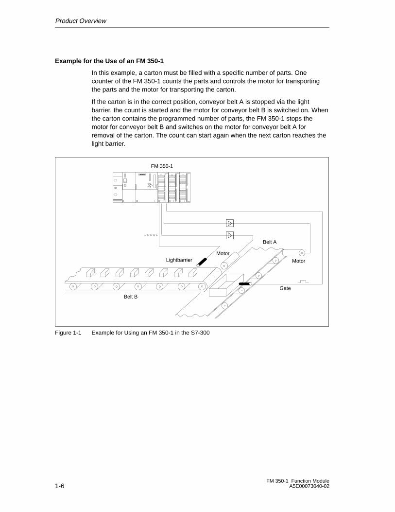
Example for the Use of an FM 350-1
In this example, a carton must be filled with a specific number of parts. Onecounter of the FM 350-1 counts the parts and controls the motor for transportingthe parts and the motor for transporting the carton.
If the carton is in the correct position, conveyor belt A is stopped via the lightbarrier, the count is started and the motor for conveyor belt B is switched on. Whenthe carton contains the programmed number of parts, the FM 350-1 stops themotor for conveyor belt B and switches on the motor for conveyor belt A forremoval of the carton. The count can start again when the next carton reaches thelight barrier.
Gate
Motor
MotorLightbarrier
FM 350-1
Belt A
Belt B
Figure 1-1 Example for Using an FM 350-1 in the S7-300
Product Overview
1-7FM 350-1 Function ModuleA5E00073040-02
1.3 FM 350-1 Hardware
View of Module
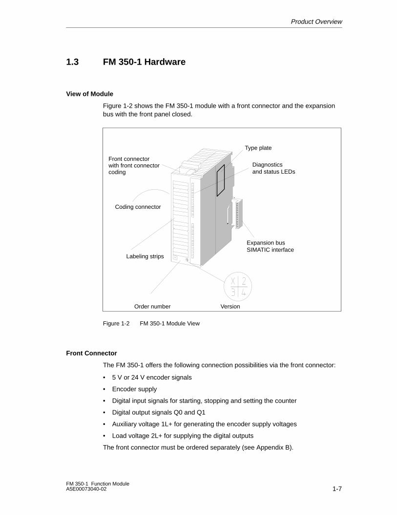
Figure 1-2 shows the FM 350-1 module with a front connector and the expansionbus with the front panel closed.
Labeling strips
Expansion busSIMATIC interface
Version
Coding connector
Diagnosticsand status LEDs
Order number
Front connector with front connectorcoding
Type plate
Figure 1-2 FM 350-1 Module View
Front Connector
The FM 350-1 offers the following connection possibilities via the front connector:
• 5 V or 24 V encoder signals
• Encoder supply
• Digital input signals for starting, stopping and setting the counter
• Digital output signals Q0 and Q1
• Auxiliary voltage 1L+ for generating the encoder supply voltages
• Load voltage 2L+ for supplying the digital outputs
The front connector must be ordered separately (see Appendix B).
Product Overview
1-8FM 350-1 Function Module
A5E00073040-02
Front Connector Coding
When you press the front connector from the wiring position to the operatingposition, the front connector coding engages. Thereafter, this front connector canonly be attached to an FM 350-1 module.
Coding Connector
The coding connector is used to set the FM 350-1 to the encoder signals used. Thefollowing settings are possible:
Coding Connector at Setting... ...Corresponds to the Following Encoder Signals
A 5 V differential signals (state as supplied)
D 24 V signals
The coding connector is located on the left side of the FM 350-1.
Labeling Strips
Enclosed with the module is a labeling strip on which you can write your relevantsignal names.
The pin assignments are printed on the inside of the front panel.
Order Number and Version
The order number and the version of the FM 350-1 are given at the bottom of thefront panel.
Firmware Version
The firmware version indicates the version at the time of delivery. It can be updatedwith a firmware update.
Expansion Bus
Communications within one tier of the S7-300/M7-300 takes place over theexpansion bus. The expansion bus is supplied with the FM 350-1.
Product Overview
1-9FM 350-1 Function ModuleA5E00073040-02
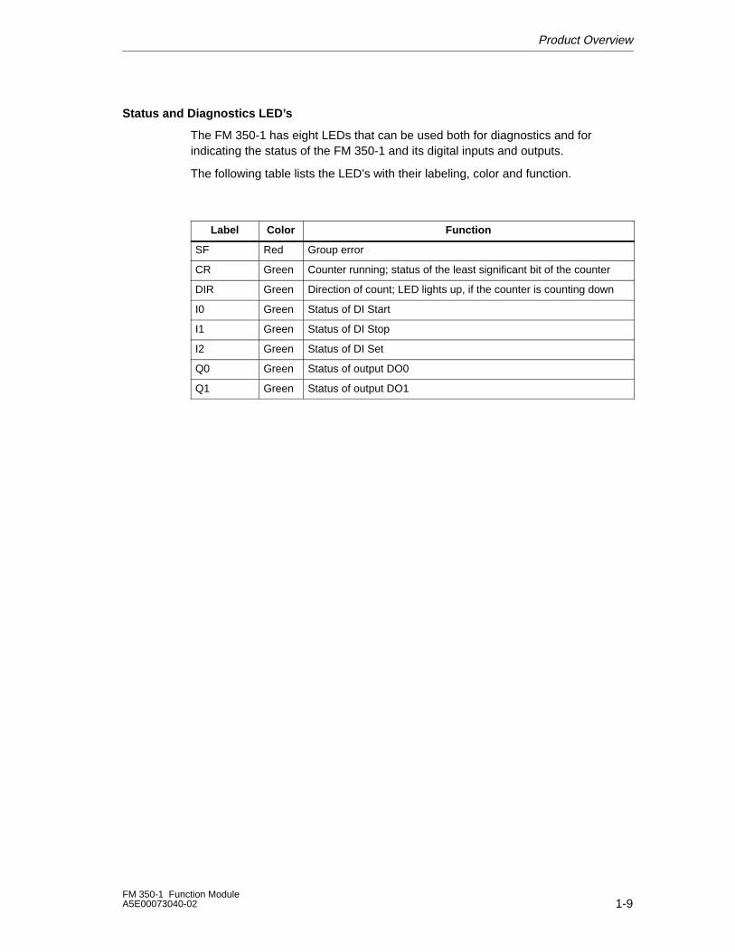
Status and Diagnostics LED’s
The FM 350-1 has eight LEDs that can be used both for diagnostics and forindicating the status of the FM 350-1 and its digital inputs and outputs.
The following table lists the LED’s with their labeling, color and function.
Label Color Function
SF Red Group error
CR Green Counter running; status of the least significant bit of the counter
DIR Green Direction of count; LED lights up, if the counter is counting down
I0 Green Status of DI Start
I1 Green Status of DI Stop
I2 Green Status of DI Set
Q0 Green Status of output DO0
Q1 Green Status of output DO1
Product Overview
1-10FM 350-1 Function Module
A5E00073040-02
1.4 FM 350-1 Software
Configuration Package
To integrate the FM 350-1 into the S7-300, use the configuration package on thesupplied CD . This contains:
• Parameter assignment software with parameter dialogs
• Software for the CPU (blocks)
• Documentation
The software for integrating the FM 350-1 into the M7-300 is described inChapters 6 and 11.
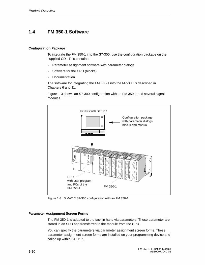
Figure 1-3 shows an S7-300 configuration with an FM 350-1 and several signalmodules.
CPUwith user programand FCs of theFM 350-1 FM 350-1
PC/PG with STEP 7
Configuration packagewith parameter dialogs,blocks and manual
Figure 1-3 SIMATIC S7-300 configuration with an FM 350-1
Parameter Assignment Screen Forms
The FM 350-1 is adapted to the task in hand via parameters. These parameter arestored in an SDB and transferred to the module from the CPU.
You can specify the parameters via parameter assignment screen forms. Theseparameter assignment screen forms are installed on your programming device andcalled up within STEP 7.

Product Overview
1-11FM 350-1 Function ModuleA5E00073040-02
Software for the S7-300 CPU
The software for the CPU consists of the FC CNT_CTL1 function called in the userprogram of the CPU. This FC enables communication between the CPU and theFM 350-1. There is also the FC DIAG_INF function for the FM 350-1, with whichyou can transfer diagnostics information into the DB of the FC CNT_CTL1.

Product Overview
1-12FM 350-1 Function Module
A5E00073040-02
Installing and Removing the FM 350-1
2-1FM 350-1 Function ModuleA5E00073040-02
Installing and Removing the FM 350-1
This Chapter...
This chapter contains information on installing and removing the FM 350-1.
• You will learn what you must look out for when installing. You will get notes andhints on configuring, arranging and installing an FM 350-1.
• You will learn, step-by-step, how to install and remove an FM 350-1.
Chapter Overview
Section Description Page
2.1 Preparing the Installation 2-2
2.2 Installing and Removing the FM 350-1 2-3
2
Installing and Removing the FM 350-1
2-2FM 350-1 Function Module
A5E00073040-02
2.1 Preparing the Installation
Important Safety Rules
There are important rules you must observe for integrating an S7-300 with anFM 350-1 into a plant or a system. These rules and regulations are explained inmanual /1/.
Vertical or Horizontal Arrangement
Horizontal arrangement is preferable. For vertical arrangement, you must observethe restricted ambient temperatures (max. 40° C).
Defining the Slots
The 350-1 function module can be installed like a signal module in any of slots 4 to 11.
Mechanical Configuration
Manual /1/ describes the possibilities open to you for mechanical installation andhow to proceed when configuring. The following gives only a few supplementarynotes.
1. A maximum of eight SMs or FMs are permissible per rack.
2. The maximum number is restricted by the width of the modules or the length ofyour mounting rail. The FM 350-1 requires an installation width of 40 mm.
3. The maximum number is restricted by the total current consumptions of allmodules to the right of the CPU from the 5 V backplane bus supply. The currentconsumption of the FM 350-1 is 160 mA.
4. The maximum number is restricted by the memory required by the CPUsoftware for communications with the FM 350-1.
Installing and Removing the FM 350-1
2-3FM 350-1 Function ModuleA5E00073040-02
2.2 Installing and Removing the FM 350-1
Rules
No special protection measures (ESD guidelines) are required for installing anFM 350-1.
Tools Required
You require a 4.5 mm flat-bladed screwdriver for installing and removing theFM 350-1.
Setting the Signal Type (Coding Key)
Before mounting an FM 350-1 on the mounting rail, you must place the coding keyin the correct position. The following table assigns the position of the coding key tothe signal type used. (refer also to /1/)
Position of the Coding Connector Signal Type
A 5 V differential signals
D 24 V signals
Installing and Removing the FM 350-1
2-4FM 350-1 Function Module
A5E00073040-02
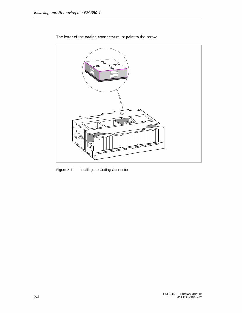
The letter of the coding connector must point to the arrow.
Figure 2-1 Installing the Coding Connector
Installing and Removing the FM 350-1
2-5FM 350-1 Function ModuleA5E00073040-02
Installation Procedure
How to mount the FM 350-1 on the mounting rail:
1. Switch the CPU to the STOP state.
2. The FM 350-1 is supplied with an expansion bus. Plug this into the busconnector of the module to the left of the FM 350-1. (The bus connector islocated on the back and you may have to loosen the neighboring module.)
3. Hang the FM 350-1 onto the rail and swing it down.
4. Tighten the screw on the FM 350-1 (tightening torque approximately 0.8 to 1.1 Nm).
If further modules are to be installed to the right of the FM 350-1, first connectthe expansion bus of the next module to the right-hand backplane busconnector of the FM 350-1.
If the FM 350-1 is the last module in the rack, do not connect an expansionbus!
5. Label the FM 350-1 with its slot number. Use the number wheel supplied withthe CPU for this purpose.
Manual /1/ describes the numbering scheme you must use and how to connectthe slot numbers.
6. Install the shield attachment.
Procedure for Removal/Replacement of Modules
How to remove the FM 350-1:
1. Switch off the auxiliary voltage and the load voltage at the front connector.
2. Switch the CPU to the STOP state.
3. Open the front panel. If necessary, remove the labeling strip.
4. Release the front connector and pull it out.
5. Loosen the fixing screw on the module.
6. Swing the module out of the mounting rail and unhook it.
7. Install the new module if applicable.
Further Notes
Manual /1/ contains further notes on installing and removing modules.

Installing and Removing the FM 350-1
2-6FM 350-1 Function Module
A5E00073040-02
Wiring the FM 350-1
3-1FM 350-1 Function ModuleA5E00073040-02
Wiring the FM 350-1
Chapter Overview
This chapter contains the following information on wiring the FM 350-1:
• Terminal assignments of the front connector.
• The function of the connections.
• Notes on selecting cables.
• The steps you must execute when wiring the front connector.
• The status of the module after wiring and switching on the power supply.
Section Description Page
3.1 Terminal Assignments of the Front Connector 3-2
3.2 Wiring the Front Connector 3-7
3.3 Module Status After Switching On 3-10
3
Wiring the FM 350-1
3-2FM 350-1 Function Module
A5E00073040-02
3.1 Terminal Assignments of the Front Connector
Front Connector
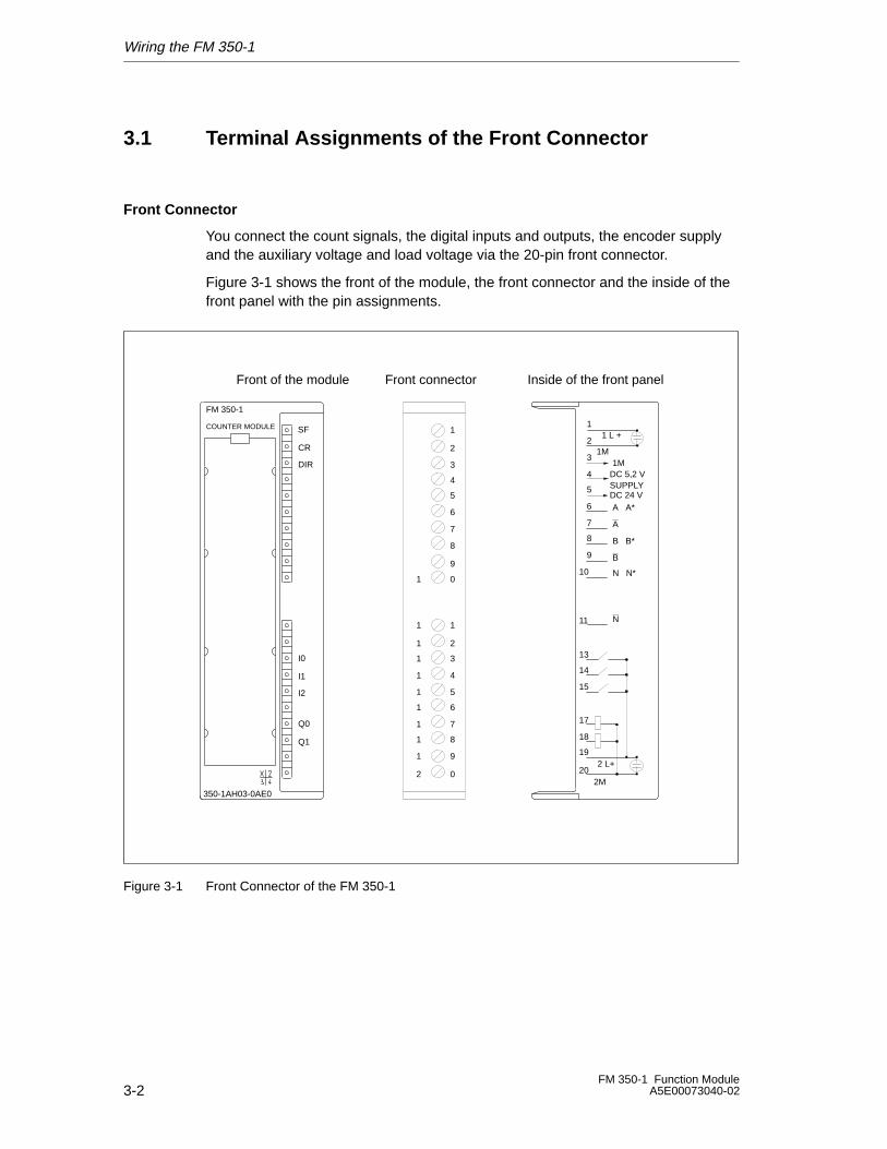
You connect the count signals, the digital inputs and outputs, the encoder supplyand the auxiliary voltage and load voltage via the 20-pin front connector.
Figure 3-1 shows the front of the module, the front connector and the inside of thefront panel with the pin assignments.
DIR
Q1
Q0
I2
I1
I0
1
2
3
4
5
6
7
8
9
0
1
2
3
4
5
6
7
8
9
0
1
1
1
1
1
1
1
1
1
1
2
1
2
3
4
5
6
7
8
9
10
1 L +
1MDC 5,2 VSUPPLYDC 24 VA A*
A
B B*
B
N N*
N
20
19
18
17
15
14
13
11
2 L+
1M
Front connector
2M
CR
350-1AH03-0AE0
COUNTER MODULE
Front of the module Inside of the front panel
SF
FM 350-1
Figure 3-1 Front Connector of the FM 350-1
Wiring the FM 350-1
3-3FM 350-1 Function ModuleA5E00073040-02
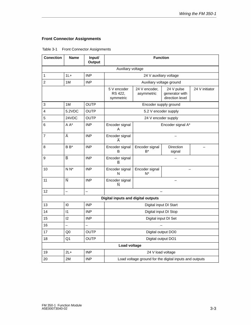
Front Connector Assignments
Table 3-1 Front Connector Assignments
Conection Name Input/Output
Function
Auxiliary voltage
1 1L+ INP 24 V auxiliary voltage
2 1M INP Auxiliary voltage ground
5 V encoderRS 422,
symmetric
24 V encoder,asymmetric
24 V pulsegenerator withdirection level
24 V initiator
3 1M OUTP Encoder supply ground
4 5.2VDC OUTP 5.2 V encoder supply
5 24VDC OUTP 24 V encoder supply
6 A A* INP Encoder signalA
Encoder signal A*
7 A INP Encoder signalA
–
8 B B* INP Encoder signalB
Encoder signalB*
Directionsignal
–
9 B INP Encoder signalB
–
10 N N* INP Encoder signalN
Encoder signalN*
–
11 N INP Encoder signalN
–
12 – – –
Digital inputs and digital outputs
13 I0 INP Digital input DI Start
14 I1 INP Digital input DI Stop
15 I2 INP Digital input DI Set
16 – – –
17 Q0 OUTP Digital output DO0
18 Q1 OUTP Digital output DO1
Load voltage
19 2L+ INP 24 V load voltage
20 2M INP Load voltage ground for the digital inputs and outputs
Wiring the FM 350-1
3-4FM 350-1 Function Module
A5E00073040-02
Note
The circuits for the counter inputs (encoder supply, encoder signals) arenon-isolated to the ground of the CPU, that is, terminal 2 (1M) must have alow-resistance connection to CPU ground.
If you supply the encoders externally, you must also connect the ground of thisexternal voltage with the ground of the CPU.
Auxiliary Voltage 1L+, 1M
Connect a direct voltage of 24 V to the 1L+ and 1M terminals for the voltage supplyof the 5 V and 24 V encoders.
An integral diode protects the module from reverse polarity of the auxiliary voltage.
The module monitors the connection of the auxiliary voltage.
5.2 VDC Encoder Supply
The module generates a voltage of 5.2 V from the auxiliary voltage 1L+/1M at amaximum current of 300 mA that is available at the ‘5.2 VDC’ connection for theshort-circuit-proof supply of a 5 V encoder. The encoder supply is checked forshort-circuit.
24 VDC Encoder Supply
For the 24 V voltage supply of an encoder, the voltage 1L+/1M is made availableand short-circuit proof at the ‘24 VDC’ output. The encoder supply is monitored forshort-circuit.
5 V Encoder Signals A/A, B/B, N and N
You can connect incremental encoders with 5 V differential signals to the frontconnector in accordance with RS 422, that is, incremental encoders with thedifferential signals, A/A, B/B, N and N.
The signals A/A, B/B, N and N are connected via the terminals so labeled.
The signals N and N are only connected if you want to set the counter to the zeromark of the encoder.
The inputs are not electrically isolated from the bus of the S7-300 (refer to the noteon this page).
Wiring the FM 350-1
3-5FM 350-1 Function ModuleA5E00073040-02
24 V Encoder Signals A*, B* and N*
24 V signals are represented by the letters A*, B* and N*.
You can connect three different encoder types to each counter:
• Incremental encoders with 24 V signals:
The signals A*, B* and N* are connected via the terminals so labeled.
• Pulse encoders without direction level:
The signal is connected to terminal A*.
• Pulse encoders with direction level:
The count signal is connected to terminal A*. The direction level is connected toterminal B*.
The inputs are not galvanically isolated from the S7-300 bus (see note onpage 3-3).
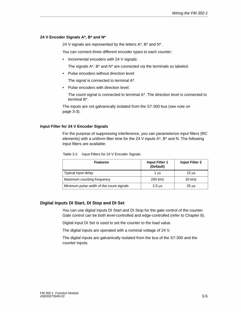
Input Filter for 24 V Encoder Signals
For the purpose of suppressing interference, you can parameterize input filters (RCelements) with a uniform filter time for the 24 V inputs A*, B* and N. The followinginput filters are available:
Table 3-2 Input Filters for 24 V Encoder Signals
Features Input Filter 1(Default)
Input Filter 2
Typical input delay 1 �s 15 �s
Maximum counting frequency 200 kHz 20 kHz
Minimum pulse width of the count signals 2.5 �s 25 �s
Digital Inputs DI Start, DI Stop and DI Set
You can use digital inputs DI Start and DI Stop for the gate control of the counter.Gate control can be both level-controlled and edge-controlled (refer to Chapter 8).
Digital input DI Set is used to set the counter to the load value.
The digital inputs are operated with a nominal voltage of 24 V.
The digital inputs are galvanically isolated from the bus of the S7-300 and thecounter inputs.
Wiring the FM 350-1
3-6FM 350-1 Function Module
A5E00073040-02
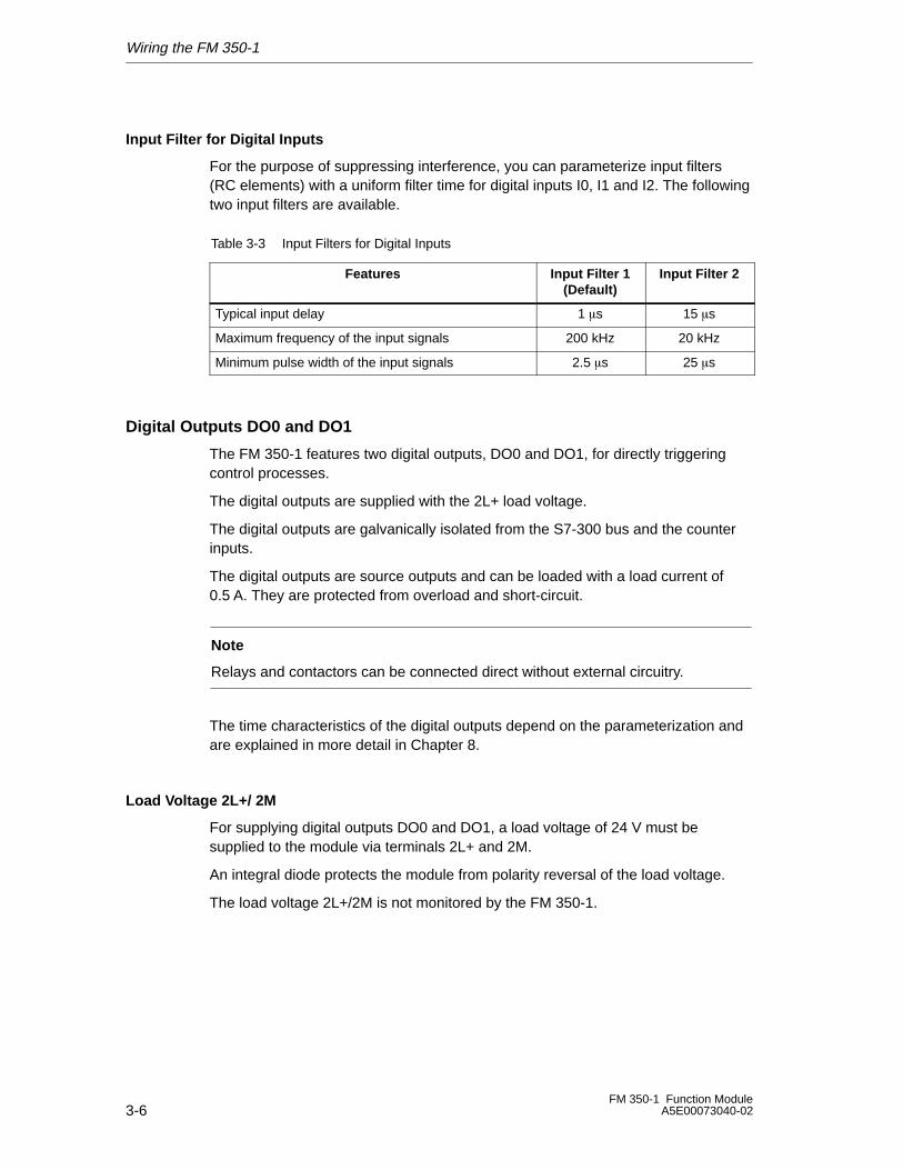
Input Filter for Digital Inputs
For the purpose of suppressing interference, you can parameterize input filters(RC elements) with a uniform filter time for digital inputs I0, I1 and I2. The followingtwo input filters are available.
Table 3-3 Input Filters for Digital Inputs
Features Input Filter 1(Default)
Input Filter 2
Typical input delay 1 �s 15 �s
Maximum frequency of the input signals 200 kHz 20 kHz
Minimum pulse width of the input signals 2.5 �s 25 �s
Digital Outputs DO0 and DO1
The FM 350-1 features two digital outputs, DO0 and DO1, for directly triggeringcontrol processes.
The digital outputs are supplied with the 2L+ load voltage.
The digital outputs are galvanically isolated from the S7-300 bus and the counterinputs.
The digital outputs are source outputs and can be loaded with a load current of0.5 A. They are protected from overload and short-circuit.
Note
Relays and contactors can be connected direct without external circuitry.
The time characteristics of the digital outputs depend on the parameterization andare explained in more detail in Chapter 8.
Load Voltage 2L+/ 2M
For supplying digital outputs DO0 and DO1, a load voltage of 24 V must besupplied to the module via terminals 2L+ and 2M.
An integral diode protects the module from polarity reversal of the load voltage.
The load voltage 2L+/2M is not monitored by the FM 350-1.
Wiring the FM 350-1
3-7FM 350-1 Function ModuleA5E00073040-02
3.2 Wiring the Front Connector
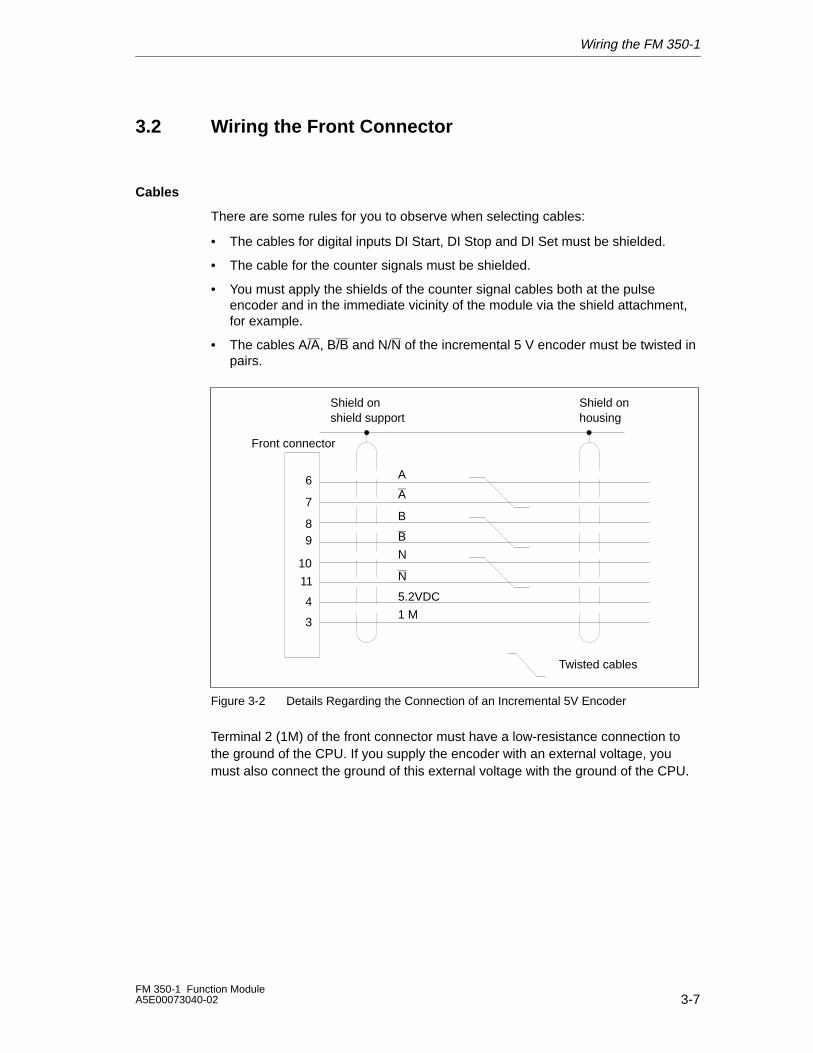
Cables
There are some rules for you to observe when selecting cables:
• The cables for digital inputs DI Start, DI Stop and DI Set must be shielded.
• The cable for the counter signals must be shielded.
• You must apply the shields of the counter signal cables both at the pulseencoder and in the immediate vicinity of the module via the shield attachment,for example.
• The cables A/A, B/B and N/N of the incremental 5 V encoder must be twisted inpairs.
Shield onshield support
Shield onhousing
A
B
N
5.2VDC
1 M
6
7
89
10
Front connector
11
3
4
N
B
A
Twisted cables
Figure 3-2 Details Regarding the Connection of an Incremental 5V Encoder
Terminal 2 (1M) of the front connector must have a low-resistance connection tothe ground of the CPU. If you supply the encoder with an external voltage, youmust also connect the ground of this external voltage with the ground of the CPU.
Wiring the FM 350-1
3-8FM 350-1 Function Module
A5E00073040-02
Shield onshield support
Shield onhousing
A *
B *
N *
24VDC
1 M
6
8
10
5
3
Front connector
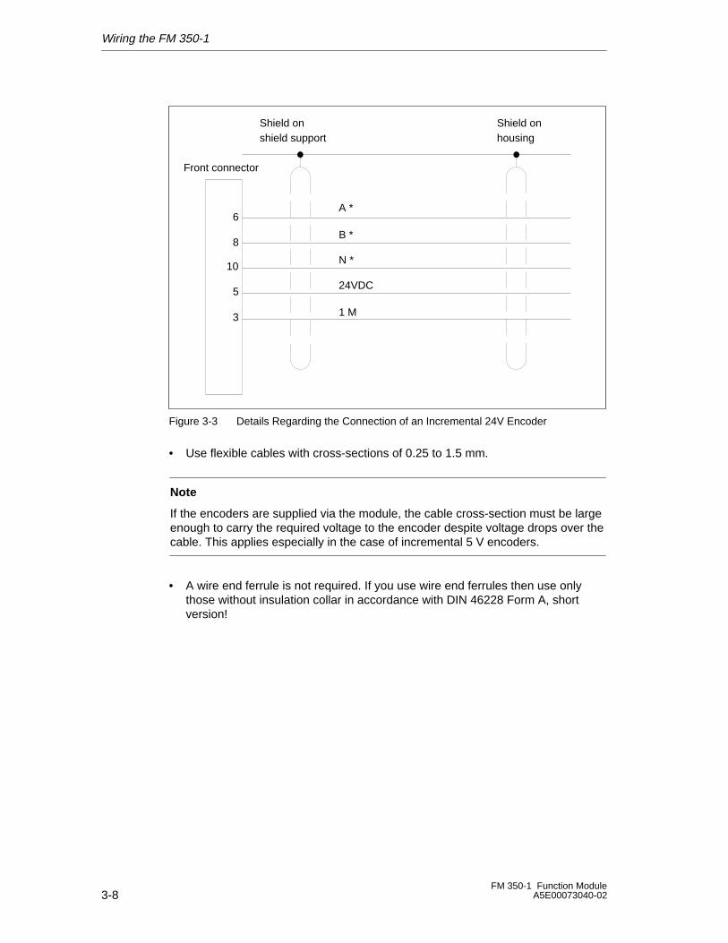
Figure 3-3 Details Regarding the Connection of an Incremental 24V Encoder
• Use flexible cables with cross-sections of 0.25 to 1.5 mm.
Note
If the encoders are supplied via the module, the cable cross-section must be largeenough to carry the required voltage to the encoder despite voltage drops over thecable. This applies especially in the case of incremental 5 V encoders.
• A wire end ferrule is not required. If you use wire end ferrules then use onlythose without insulation collar in accordance with DIN 46228 Form A, shortversion!
Wiring the FM 350-1
3-9FM 350-1 Function ModuleA5E00073040-02
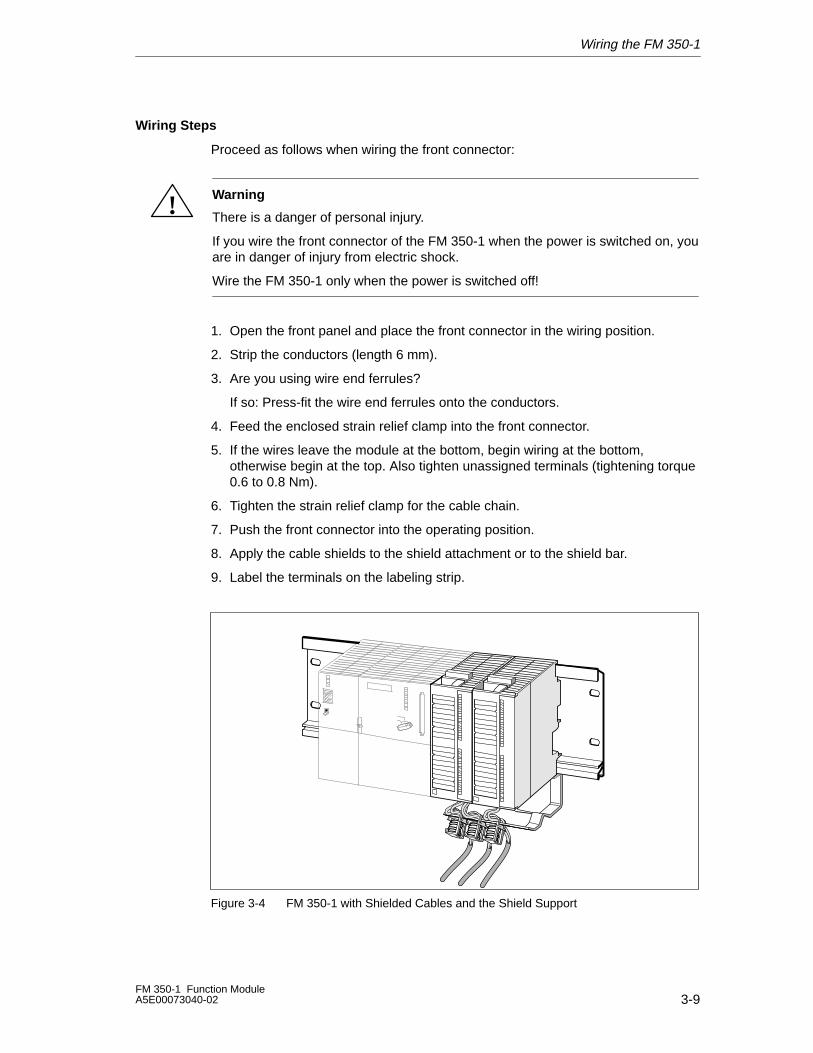
Wiring Steps
Proceed as follows when wiring the front connector:
! Warning
There is a danger of personal injury.
If you wire the front connector of the FM 350-1 when the power is switched on, youare in danger of injury from electric shock.
Wire the FM 350-1 only when the power is switched off!
1. Open the front panel and place the front connector in the wiring position.
2. Strip the conductors (length 6 mm).
3. Are you using wire end ferrules?
If so: Press-fit the wire end ferrules onto the conductors.
4. Feed the enclosed strain relief clamp into the front connector.
5. If the wires leave the module at the bottom, begin wiring at the bottom,otherwise begin at the top. Also tighten unassigned terminals (tightening torque0.6 to 0.8 Nm).
6. Tighten the strain relief clamp for the cable chain.
7. Push the front connector into the operating position.
8. Apply the cable shields to the shield attachment or to the shield bar.
9. Label the terminals on the labeling strip.
Figure 3-4 FM 350-1 with Shielded Cables and the Shield Support
Wiring the FM 350-1
3-10FM 350-1 Function Module
A5E00073040-02
3.3 Module Status After Switching On
Default Setting
The state in which the module is after the power supply is turned on whenparameters are still not being transmitted:
• No gate – in other words, gate open
• Counter inputs with default setting for 5 V differential signals, track B notinverted; single evaluation (see 9-4);
• Count limit 32 bits
• Counter status zero
• Counter setting with input DI Set (and zero mark) inhibited
• Input delay for digital inputs I0, I1 and I2: typically 1 �s(max. frequency: 200 kHz, minimum pulse width: 2.5 �s)
• Input delay for 24 V counter inputs: typically 1 s(max. frequency: 200 kHz, minimum pulse width: 2.5 �s)
• Outputs DO0 and DO1 disabled
• Pulse duration = 0
• No process interrupts set
• Operating mode ’Continuous count’ set
• Status signals are updated
Assigning Parameters to the FM 350-1
4-1FM 350-1 Function ModuleA5E00073040-02
Assigning Parameters to the FM 350-1
Chapter Overview
In this chapter, you will learn how to install and start parameter assignment screenforms.
The parameter assignment screen forms have an integral help function thatsupports you in parameterizing and starting up the FM 350-1.
Section Description Page
4.1 Installing and Calling Parameter Assignment Screen Forms 4-2
4
Assigning Parameters to the FM 350-1
4-2FM 350-1 Function Module
A5E00073040-02
4.1 Installing and Calling Parameter Assignment ScreenForms
Marginal Conditions
The following conditions apply for transferring parameter assignment data to theCPU:
• STEP 7 (≥version 5.0) is correctly installed on your PG.The following instructions refer specifically to STEP 7 (version 5.2)
• The programming device must be correctly connected to the CPU
• The CPU must be in STOP
Note
You must not plug in or remove any S7-300 modules during data exchange overthe MPI!
Installing the Parameter Assignment Screens
The whole configuration package is located on the enclosed CD. To install theconfiguration package, perform the following steps:
1. Uninstall your present configuration package, if any.
2. Insert the CD into the CD drive on your PG or PC.
3. In Windows 95/Windows NT/Windows 98, open the dialog box for installingsoftware by double-clicking on the “Software” icon on the “Control Panel”.
4. In the dialog box, select the CD drive and, in the directory calledFMx50-1\Disk1 , select the Setup.exe file and start the installation operation.
5. Follow the successive instructions displayed by the installation program.
Result: The components of the configuration package are installed in thefollowing directories:
– SIEMENS\STEP7\S7LIBS\FMx50LIB: FCs, UDTs
– SIEMENS\STEP7\S7FCOUNT: configuration software, Readme, online Help
– SIEMENS\STEP7\EXAMPLES: Examples
– SIEMENS\STEP7\S7MANUAL\S7FCOUNT: Getting Started, manuals
NoteIf you selected a directory other than SIEMENS\STEP7 when you installedSTEP 7, that directory will be entered.
Assigning Parameters to the FM 350-1
4-3FM 350-1 Function ModuleA5E00073040-02
Calling the Parameter Assignment Screens
To call the parameter assignment screens of the FM 350-1, perform the followingsteps:
1. Place the order number on a vacant slot.
2. Double-click on the order number.
3. Acknowledge with “OK” any dialog box which may appear and prompt you tosave the configuration.

Assigning Parameters to the FM 350-1
4-4FM 350-1 Function Module
A5E00073040-02
5-1FM 350-1 Function ModuleA5E00073040-02
Programming the FM 350-1
Chapter Overview
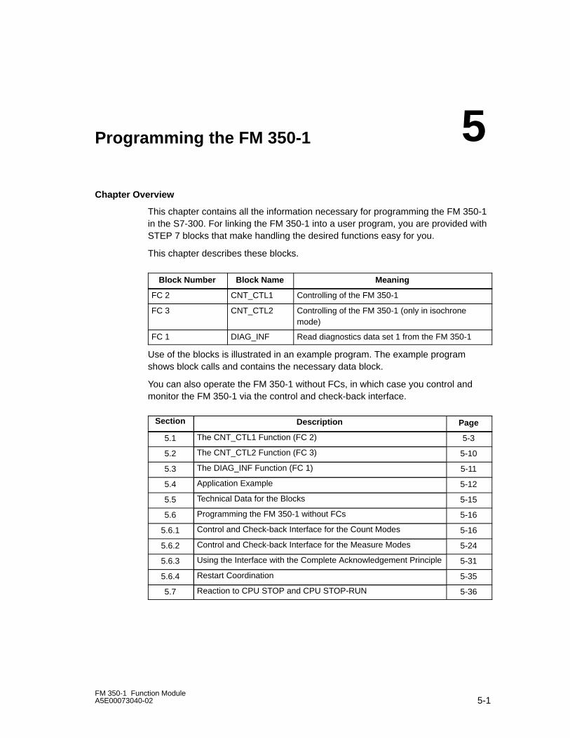
This chapter contains all the information necessary for programming the FM 350-1in the S7-300. For linking the FM 350-1 into a user program, you are provided withSTEP 7 blocks that make handling the desired functions easy for you.
This chapter describes these blocks.
Block Number Block Name Meaning
FC 2 CNT_CTL1 Controlling of the FM 350-1
FC 3 CNT_CTL2 Controlling of the FM 350-1 (only in isochronemode)
FC 1 DIAG_INF Read diagnostics data set 1 from the FM 350-1
Use of the blocks is illustrated in an example program. The example programshows block calls and contains the necessary data block.
You can also operate the FM 350-1 without FCs, in which case you control andmonitor the FM 350-1 via the control and check-back interface.
Section Description Page
5.1 The CNT_CTL1 Function (FC 2) 5-3
5.2 The CNT_CTL2 Function (FC 3) 5-10
5.3 The DIAG_INF Function (FC 1) 5-11
5.4 Application Example 5-12
5.5 Technical Data for the Blocks 5-15
5.6 Programming the FM 350-1 without FCs 5-16
5.6.1 Control and Check-back Interface for the Count Modes 5-16
5.6.2 Control and Check-back Interface for the Measure Modes 5-24
5.6.3 Using the Interface with the Complete Acknowledgement Principle 5-31
5.6.4 Restart Coordination 5-35
5.7 Reaction to CPU STOP and CPU STOP-RUN 5-36
5
Programming the FM 350-1
5-2FM 350-1 Function Module
A5E00073040-02
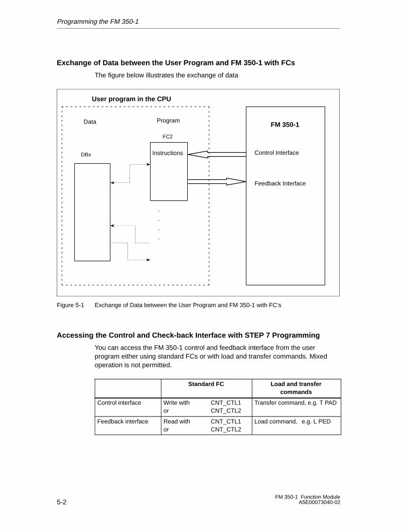
Exchange of Data between the User Program and FM 350-1 with FCs
The figure below illustrates the exchange of data
User program in the CPU
FM 350-1Data
DBx
Program
FC2
Instructions
.
.
.
.
Feedback Interface
Control Interface
Figure 5-1 Exchange of Data between the User Program and FM 350-1 with FC‘s
Accessing the Control and Check-back Interface with STEP 7 Programming
You can access the FM 350-1 control and feedback interface from the userprogram either using standard FCs or with load and transfer commands. Mixedoperation is not permitted.
Standard FC Load and transfercommands
Control interface Write with CNT_CTL1or CNT_CTL2
Transfer command, e.g. T PAD
Feedback interface Read with CNT_CTL1or CNT_CTL2
Load command, e.g. L PED
Programming the FM 350-1
5-3FM 350-1 Function ModuleA5E00073040-02
5.1 The CNT_CTL1 Function (FC 2)
Requirement
The data required for the CNT_CTL1 function is stored in a DB on the CPU. TheCNT_CTL1 function transfers data cyclically from this DB to the FM and fetchesdata from the FM.
You create the DB under STEP 7 as a data block with assigned user-specific datatype. Select UDT 2 as the source file. UDT 2 was copied to the block library called FMx50LIB when the FCs were installed. You must not modify UDT 2. Copy UDT 2together with the FCs into your project. Before programming the FM 350-1, thefollowing valid data must be assigned to the DB of the CNT_CTL1 function:
• Module address
You set the module address (base address of the FM 350-1) when configuringyour hardware.
You can enter the address automatically in the DB by selecting the module inHW Config, and then selecting a data block from the “Properties” dialog byclicking on the “Mod Addr” button.
• Channel address
The channel address is the same as the module address in pointer format.
• User data length
The user data length is 16.
You can save these data by means of a parameter assignment screen (refer to theleaflet “Getting Started with Commissioning”) or by means of the user program inthe DB.
Programming the FM 350-1
5-4FM 350-1 Function Module
A5E00073040-02
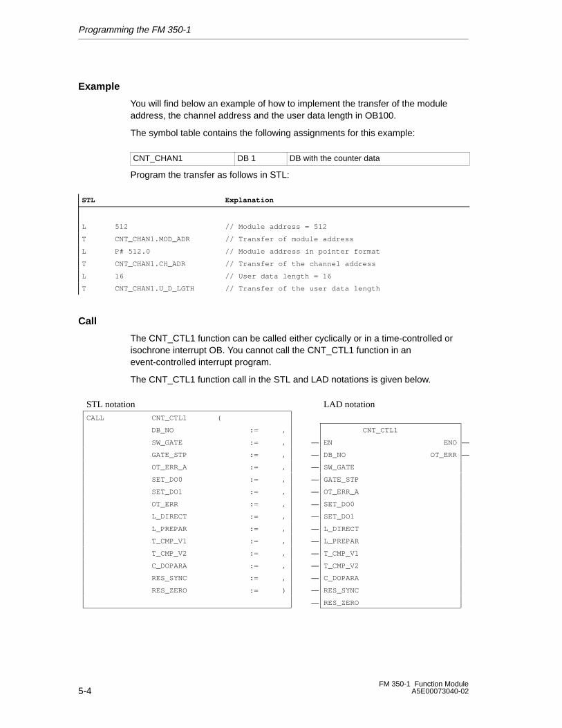
Example
You will find below an example of how to implement the transfer of the moduleaddress, the channel address and the user data length in OB100.
The symbol table contains the following assignments for this example:
CNT_CHAN1 DB 1 DB with the counter data
Program the transfer as follows in STL:
STL Explanation
L 512 // Module address = 512
T CNT_CHAN1.MOD_ADR // Transfer of module address
L P# 512.0 // Module address in pointer format
T CNT_CHAN1.CH_ADR // Transfer of the channel address
L 16 // User data length = 16
T CNT_CHAN1.U_D_LGTH // Transfer of the user data length
Call
The CNT_CTL1 function can be called either cyclically or in a time-controlled orisochrone interrupt OB. You cannot call the CNT_CTL1 function in anevent-controlled interrupt program.
The CNT_CTL1 function call in the STL and LAD notations is given below.
ÁÁÁÁÁÁÁÁÁÁÁÁÁÁÁÁÁÁÁÁÁÁÁÁÁÁÁÁÁÁÁÁÁÁ
STL notation ÁÁÁÁÁÁÁÁÁÁÁÁÁÁÁÁÁÁÁÁÁÁÁÁÁÁÁÁ
LAD notation ÁÁÁÁÁ
ÁÁÁÁÁÁÁÁÁÁÁÁÁÁÁÁÁÁÁÁÁÁÁÁÁÁÁÁÁÁÁÁÁ
CALL CNT_CTL1 ( ÁÁÁÁÁÁÁÁÁÁÁÁÁÁÁÁÁÁÁÁÁÁÁÁÁÁÁÁ
ÁÁÁÁ
ÁÁÁÁÁÁÁÁÁÁÁÁÁÁÁÁÁÁÁÁÁÁÁÁÁÁÁÁÁÁÁÁÁÁDB_NO := ,
ÁÁÁÁÁÁÁÁÁÁÁÁÁÁÁÁÁÁÁÁÁÁÁÁÁÁÁÁCNT_CTL1
ÁÁÁÁÁ
ÁÁÁÁÁÁÁÁÁÁÁÁÁÁÁÁÁÁÁÁÁÁÁÁÁÁÁÁÁÁÁÁÁSW_GATE := ,
ÁÁÁÁÁÁ�ÁÁÁÁÁÁÁÁÁÁÁÁÁÁÁÁÁÁÁÁÁÁEN ENO
ÁÁÁÁ�Á
ÁÁÁÁÁÁÁÁÁÁÁÁÁÁÁÁÁÁÁÁÁÁÁÁÁÁÁÁÁÁÁÁÁ
GATE_STP := ,ÁÁÁÁÁÁ
�ÁÁÁÁÁÁÁÁÁÁÁÁÁÁÁÁÁÁÁÁÁÁ
DB_NO OT_ERRÁÁÁÁ�
ÁÁÁÁÁÁÁÁÁÁÁÁÁÁÁÁÁÁÁÁÁÁÁÁÁÁÁÁÁÁÁÁÁÁ
OT_ERR_A := ,ÁÁÁÁÁÁ
�ÁÁÁÁÁÁÁÁÁÁÁÁÁÁÁÁÁÁÁÁÁÁ
SW_GATE ÁÁÁÁÁ
ÁÁÁÁÁÁÁÁÁÁÁÁÁÁÁÁÁÁÁÁÁÁÁÁÁÁÁÁÁÁÁÁÁ
SET_DO0 := ,ÁÁÁÁÁÁ
�ÁÁÁÁÁÁÁÁÁÁÁÁÁÁÁÁÁÁÁÁÁÁ
GATE_STP ÁÁÁÁÁ
ÁÁÁÁÁÁÁÁÁÁÁÁÁÁÁÁÁÁÁÁÁÁÁÁÁÁÁÁÁÁÁÁÁ
SET_DO1 := ,ÁÁÁÁÁÁ
�ÁÁÁÁÁÁÁÁÁÁÁÁÁÁÁÁÁÁÁÁÁÁ
OT_ERR_A ÁÁÁÁÁ
ÁÁÁÁÁÁÁÁÁÁÁÁÁÁÁÁÁÁÁÁÁÁÁÁÁÁÁÁÁÁÁÁÁ
OT_ERR := ,ÁÁÁÁÁÁ
�ÁÁÁÁÁÁÁÁÁÁÁÁÁÁÁÁÁÁÁÁÁÁ
SET_DO0 ÁÁÁÁÁÁÁÁÁÁÁÁÁÁÁÁÁÁÁÁÁL_DIRECT := ,ÁÁÁ�ÁÁÁÁÁÁÁÁÁÁÁSET_DO1 ÁÁÁ
ÁÁÁÁÁÁÁÁÁÁÁÁÁÁÁÁÁÁÁÁÁÁÁÁÁÁÁÁÁÁÁÁÁL_PREPAR := ,
ÁÁÁÁÁÁ�ÁÁÁÁÁÁÁÁÁÁÁÁÁÁÁÁÁÁÁÁÁÁL_DIRECT
ÁÁÁÁÁ
ÁÁÁÁÁÁÁÁÁÁÁÁÁÁÁÁÁÁÁÁÁÁÁÁÁÁÁÁÁÁÁÁÁ
T_CMP_V1 := ,ÁÁÁÁÁÁ
�
ÁÁÁÁÁÁÁÁÁÁÁÁÁÁÁÁÁÁÁÁÁÁ
L_PREPARÁÁÁÁÁ
ÁÁÁÁÁÁÁÁÁÁÁÁÁÁÁÁÁÁÁÁÁÁÁÁÁÁÁÁÁÁÁÁÁ
T_CMP_V2 := ,ÁÁÁÁÁÁ
�ÁÁÁÁÁÁÁÁÁÁÁÁÁÁÁÁÁÁÁÁÁÁ
T_CMP_V1ÁÁÁÁÁ
ÁÁÁÁÁÁÁÁÁÁÁÁÁÁÁÁÁÁÁÁÁÁÁÁÁÁÁÁÁÁÁÁÁ
C_DOPARA := ,ÁÁÁÁÁÁ
�ÁÁÁÁÁÁÁÁÁÁÁÁÁÁÁÁÁÁÁÁÁÁ
T_CMP_V2 ÁÁÁÁÁ
ÁÁÁÁÁÁÁÁÁÁÁÁÁÁÁÁÁÁÁÁÁÁÁÁÁÁÁÁÁÁÁÁÁ
RES_SYNC := ,ÁÁÁÁÁÁ
�ÁÁÁÁÁÁÁÁÁÁÁÁÁÁÁÁÁÁÁÁÁÁ
C_DOPARA ÁÁÁÁÁ
ÁÁÁÁÁÁÁÁÁÁÁÁÁÁÁÁÁÁÁÁÁÁÁÁÁÁÁÁÁÁÁÁÁ
RES_ZERO := )ÁÁÁÁÁÁ
�ÁÁÁÁÁÁÁÁÁÁÁÁÁÁÁÁÁÁÁÁÁÁ
RES_SYNC ÁÁÁÁÁ
ÁÁÁÁÁÁÁÁÁÁÁÁÁÁÁÁÁÁÁÁÁÁÁÁÁÁÁÁÁÁÁÁÁ
ÁÁÁÁÁÁ
�ÁÁÁÁÁÁÁÁÁÁÁÁÁÁÁÁÁÁÁÁÁÁ
RES_ZERO ÁÁÁÁÁÁÁÁÁÁÁÁÁÁÁÁÁÁÁÁÁÁÁÁÁÁÁÁÁÁÁÁÁÁÁÁÁ
Programming the FM 350-1
5-5FM 350-1 Function ModuleA5E00073040-02
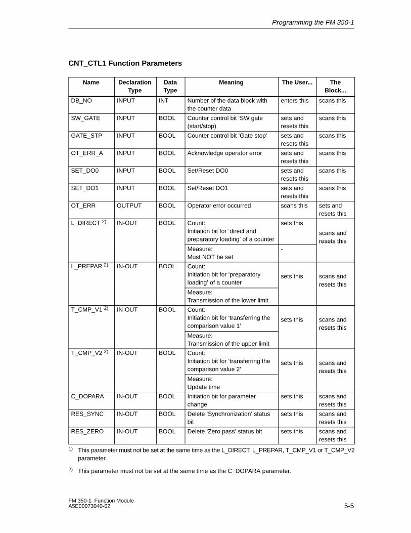
CNT_CTL1 Function Parameters
Name DeclarationType
DataType
Meaning The User... TheBlock...
DB_NO INPUT INT Number of the data block withthe counter data
enters this scans this
SW_GATE INPUT BOOL Counter control bit ‘SW gate(start/stop)
sets andresets this
scans this
GATE_STP INPUT BOOL Counter control bit ‘Gate stop’ sets andresets this
scans this
OT_ERR_A INPUT BOOL Acknowledge operator error sets andresets this
scans this
SET_DO0 INPUT BOOL Set/Reset DO0 sets andresets this
scans this
SET_DO1 INPUT BOOL Set/Reset DO1 sets andresets this
scans this
OT_ERR OUTPUT BOOL Operator error occurred scans this sets andresets this
L_DIRECT 2) IN-OUT BOOL Count:Initiation bit for ‘direct andpreparatory loading’ of a counter
sets this
scans andresets this
Measure: Must NOT be set
-resets this
L_PREPAR 2) IN-OUT BOOL Count:Initiation bit for ‘preparatoryloading’ of a counter
sets this scans andresets this
Measure:Transmission of the lower limit
resets this
T_CMP_V1 2) IN-OUT BOOL Count:Initiation bit for ‘transferring thecomparison value 1’
sets this scans andresets this
Measure:Transmission of the upper limit
resets this
T_CMP_V2 2) IN-OUT BOOL Count:Initiation bit for ‘transferring thecomparison value 2’
sets this scans andresets this
Measure:Update time
resets this
C_DOPARA IN-OUT BOOL Initiation bit for parameterchange
sets this scans andresets this
RES_SYNC IN-OUT BOOL Delete ‘Synchronization’ statusbit
sets this scans andresets this
RES_ZERO IN-OUT BOOL Delete ‘Zero pass’ status bit sets this scans andresets this
1) This parameter must not be set at the same time as the L_DIRECT, L_PREPAR, T_CMP_V1 or T_CMP_V2parameter.
2) This parameter must not be set at the same time as the C_DOPARA parameter.
Programming the FM 350-1
5-6FM 350-1 Function Module
A5E00073040-02
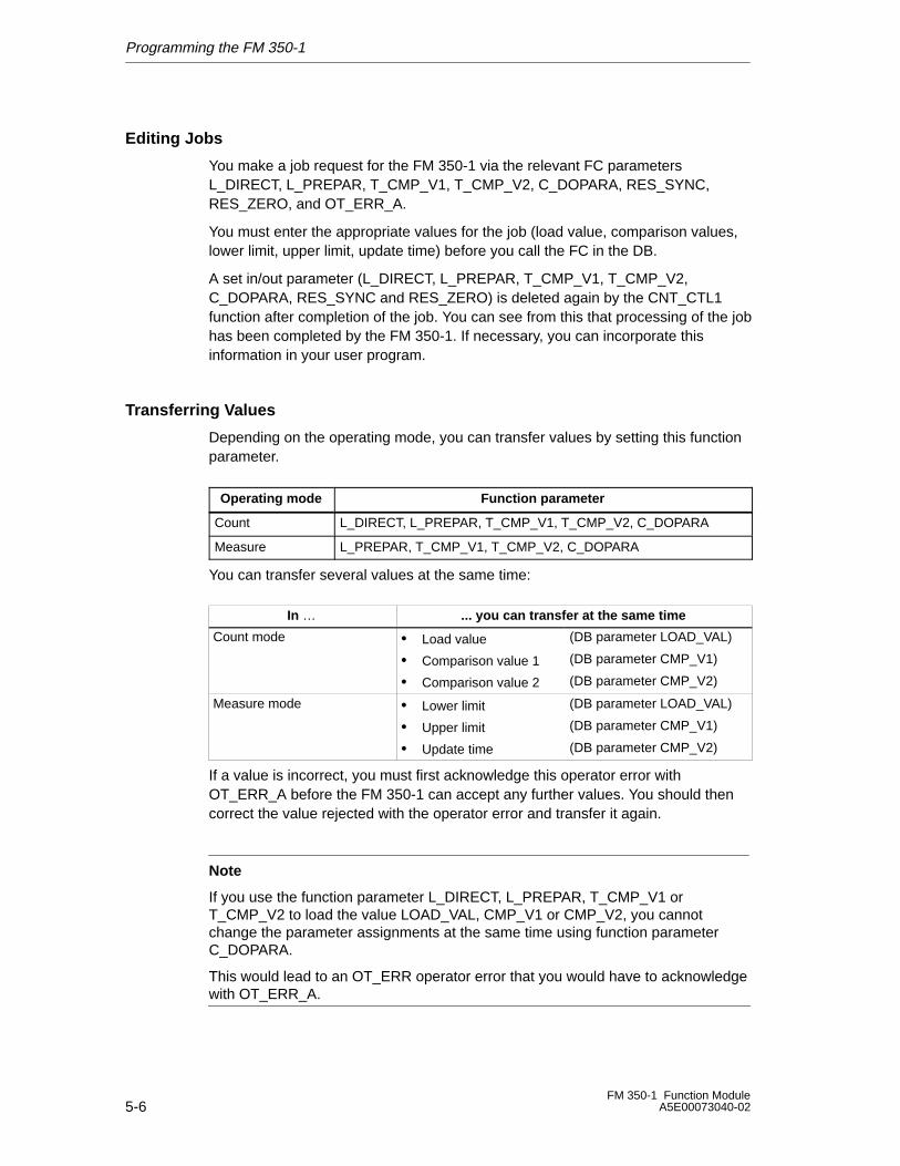
Editing Jobs
You make a job request for the FM 350-1 via the relevant FC parametersL_DIRECT, L_PREPAR, T_CMP_V1, T_CMP_V2, C_DOPARA, RES_SYNC,RES_ZERO, and OT_ERR_A.
You must enter the appropriate values for the job (load value, comparison values,lower limit, upper limit, update time) before you call the FC in the DB.
A set in/out parameter (L_DIRECT, L_PREPAR, T_CMP_V1, T_CMP_V2,C_DOPARA, RES_SYNC and RES_ZERO) is deleted again by the CNT_CTL1function after completion of the job. You can see from this that processing of the jobhas been completed by the FM 350-1. If necessary, you can incorporate thisinformation in your user program.
Transferring Values
Depending on the operating mode, you can transfer values by setting this functionparameter.
Operating mode Function parameter
Count L_DIRECT, L_PREPAR, T_CMP_V1, T_CMP_V2, C_DOPARA
Measure L_PREPAR, T_CMP_V1, T_CMP_V2, C_DOPARA
You can transfer several values at the same time:
In … ... you can transfer at the same time
Count mode • Load value
• Comparison value 1
• Comparison value 2
(DB parameter LOAD_VAL)
(DB parameter CMP_V1)
(DB parameter CMP_V2)
Measure mode • Lower limit
• Upper limit
• Update time
(DB parameter LOAD_VAL)
(DB parameter CMP_V1)
(DB parameter CMP_V2)
If a value is incorrect, you must first acknowledge this operator error withOT_ERR_A before the FM 350-1 can accept any further values. You should thencorrect the value rejected with the operator error and transfer it again.
Note
If you use the function parameter L_DIRECT, L_PREPAR, T_CMP_V1 orT_CMP_V2 to load the value LOAD_VAL, CMP_V1 or CMP_V2, you cannotchange the parameter assignments at the same time using function parameterC_DOPARA.
This would lead to an OT_ERR operator error that you would have to acknowledgewith OT_ERR_A.
Programming the FM 350-1
5-7FM 350-1 Function ModuleA5E00073040-02
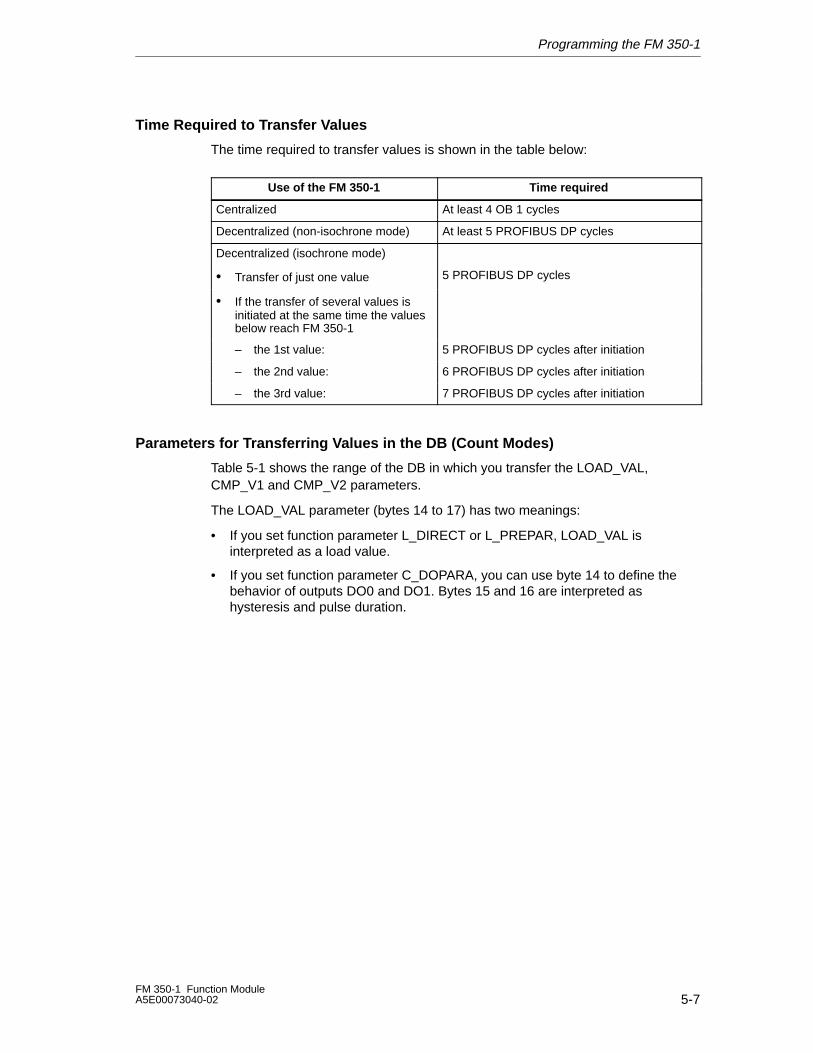
Time Required to Transfer Values
The time required to transfer values is shown in the table below:
Use of the FM 350-1 Time required
Centralized At least 4 OB 1 cycles
Decentralized (non-isochrone mode) At least 5 PROFIBUS DP cycles
Decentralized (isochrone mode)
• Transfer of just one value 5 PROFIBUS DP cycles
• If the transfer of several values isinitiated at the same time the valuesbelow reach FM 350-1
– the 1st value: 5 PROFIBUS DP cycles after initiation
– the 2nd value: 6 PROFIBUS DP cycles after initiation
– the 3rd value: 7 PROFIBUS DP cycles after initiation
Parameters for Transferring Values in the DB (Count Modes)
Table 5-1 shows the range of the DB in which you transfer the LOAD_VAL,CMP_V1 and CMP_V2 parameters.
The LOAD_VAL parameter (bytes 14 to 17) has two meanings:
• If you set function parameter L_DIRECT or L_PREPAR, LOAD_VAL isinterpreted as a load value.
• If you set function parameter C_DOPARA, you can use byte 14 to define thebehavior of outputs DO0 and DO1. Bytes 15 and 16 are interpreted ashysteresis and pulse duration.
Programming the FM 350-1
5-8FM 350-1 Function Module
A5E00073040-02
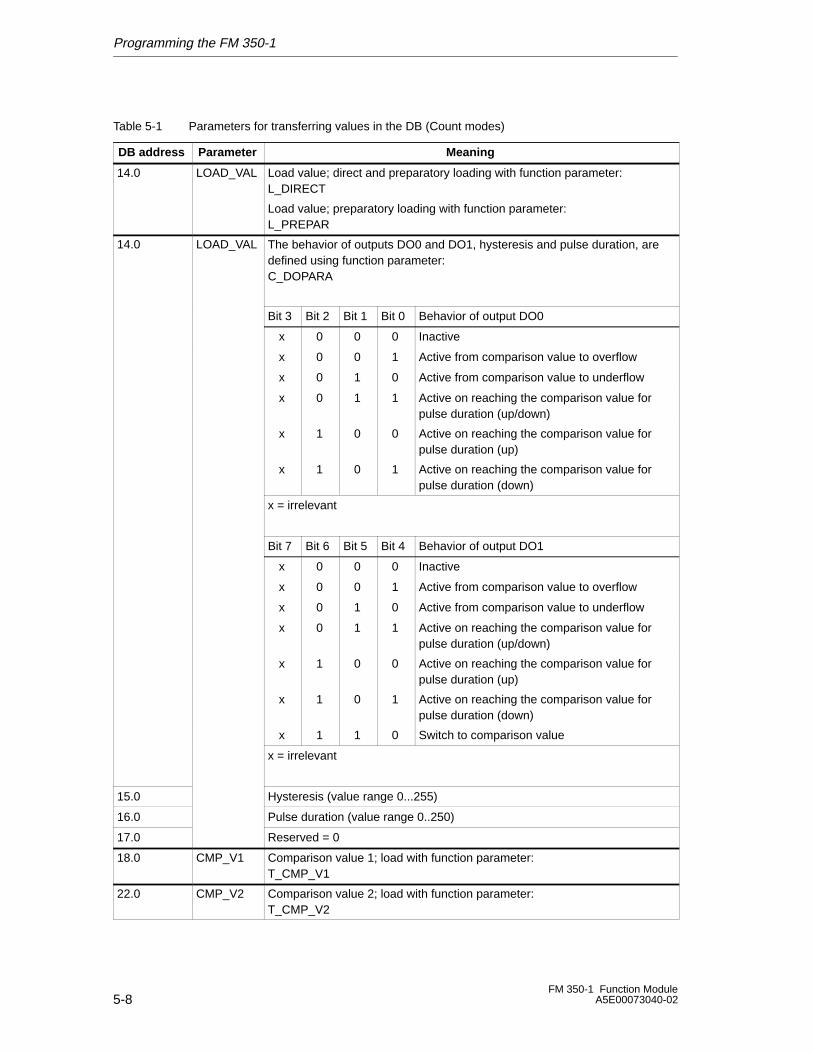
Table 5-1 Parameters for transferring values in the DB (Count modes)
DB address Parameter Meaning
14.0 LOAD_VAL Load value; direct and preparatory loading with function parameter:L_DIRECT
Load value; preparatory loading with function parameter:L_PREPAR
14.0 LOAD_VAL The behavior of outputs DO0 and DO1, hysteresis and pulse duration, aredefined using function parameter:C_DOPARA
Bit 3 Bit 2 Bit 1 Bit 0 Behavior of output DO0
x 0 0 0 Inactive
x 0 0 1 Active from comparison value to overflow
x 0 1 0 Active from comparison value to underflow
x 0 1 1 Active on reaching the comparison value forpulse duration (up/down)
x 1 0 0 Active on reaching the comparison value forpulse duration (up)
x 1 0 1 Active on reaching the comparison value forpulse duration (down)
x = irrelevant
Bit 7 Bit 6 Bit 5 Bit 4 Behavior of output DO1
x 0 0 0 Inactive
x 0 0 1 Active from comparison value to overflow
x 0 1 0 Active from comparison value to underflow
x 0 1 1 Active on reaching the comparison value forpulse duration (up/down)
x 1 0 0 Active on reaching the comparison value forpulse duration (up)
x 1 0 1 Active on reaching the comparison value forpulse duration (down)
x 1 1 0 Switch to comparison value
x = irrelevant
15.0 Hysteresis (value range 0...255)
16.0 Pulse duration (value range 0..250)
17.0 Reserved = 0
18.0 CMP_V1 Comparison value 1; load with function parameter:T_CMP_V1
22.0 CMP_V2 Comparison value 2; load with function parameter:T_CMP_V2
Programming the FM 350-1
5-9FM 350-1 Function ModuleA5E00073040-02
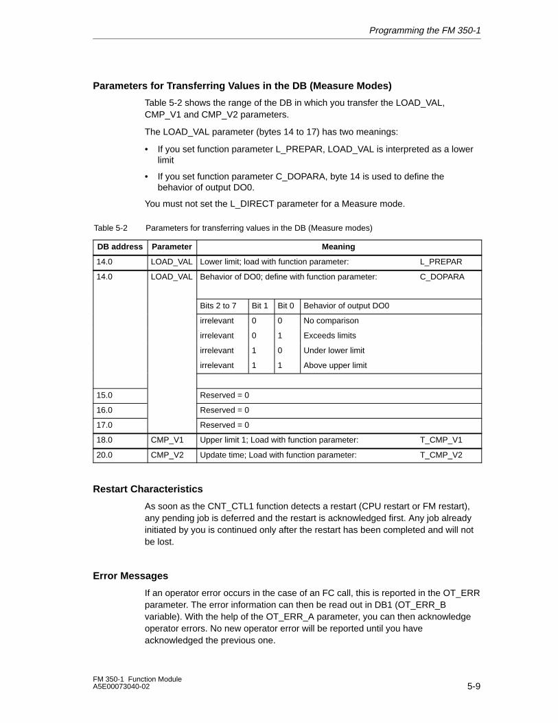
Parameters for Transferring Values in the DB (Measure Modes)
Table 5-2 shows the range of the DB in which you transfer the LOAD_VAL,CMP_V1 and CMP_V2 parameters.
The LOAD_VAL parameter (bytes 14 to 17) has two meanings:
• If you set function parameter L_PREPAR, LOAD_VAL is interpreted as a lowerlimit
• If you set function parameter C_DOPARA, byte 14 is used to define thebehavior of output DO0.
You must not set the L_DIRECT parameter for a Measure mode.
Table 5-2 Parameters for transferring values in the DB (Measure modes)
DB address Parameter Meaning
14.0 LOAD_VAL Lower limit; load with function parameter: L_PREPAR
14.0 LOAD_VAL Behavior of DO0; define with function parameter: C_DOPARA
Bits 2 to 7 Bit 1 Bit 0 Behavior of output DO0
irrelevant 0 0 No comparison
irrelevant 0 1 Exceeds limits
irrelevant 1 0 Under lower limit
irrelevant 1 1 Above upper limit
15.0 Reserved = 0
16.0 Reserved = 0
17.0 Reserved = 0
18.0 CMP_V1 Upper limit 1; Load with function parameter: T_CMP_V1
20.0 CMP_V2 Update time; Load with function parameter: T_CMP_V2
Restart Characteristics
As soon as the CNT_CTL1 function detects a restart (CPU restart or FM restart),any pending job is deferred and the restart is acknowledged first. Any job alreadyinitiated by you is continued only after the restart has been completed and will notbe lost.
Error Messages
If an operator error occurs in the case of an FC call, this is reported in the OT_ERRparameter. The error information can then be read out in DB1 (OT_ERR_Bvariable). With the help of the OT_ERR_A parameter, you can then acknowledgeoperator errors. No new operator error will be reported until you haveacknowledged the previous one.
Programming the FM 350-1
5-10FM 350-1 Function Module
A5E00073040-02
5.2 The CNT_CTL2 Function (FC 3)
Functionality
The CNT_CTL2 function essentially has the same functionality as the CNT_CTL1function (see section 5.1). The differences compared to the CNT_CTL1 functionare explained below.
Possible Uses
The CNT_CTL2 function only works in an isochrone OB.
If you call the CNT_CTL2 function in a non-isochrone OB, you will generateoperator error no. 91. You will then not be able to exchange data with theFM 350-1.
Mode of Operation
The CNT_CTL2 function is particularly suitable for applications in which you wantto send the same job (e.g. “Load comparison value”) to the FM 350-1 several timesin quick succession. While the CNT_CTL1 function is ideally used to initiate a newjob in every fifth PROFIBUS DP cycle, with the CNT_CTL2 function, this occurs inevery second PROFIBUS DP cycle.
The block is ready for a job when the relevant initiation bit is set to 0. Completion ofa job is not displayed separately.
If a communication problem or a data or operator error occurs, it cannot beassigned to a particular job, so the block will stop processing the job and willgenerate an operator error no. 90, which can be acknowledged. Once you haveacknowledged the error by setting the OT_ERR_A parameter, any outstanding jobswill be (further) processed.
Acknowledgement of an operator error is deemed to be successful if the OT_ERRparameter is reset. You should therefore leave the OT_ERR_A parameter set toguarantee acknowledgement. There is no point in initiating further jobs until theacknowledgement is successful.
Note
In isochrone mode, you cannot start several value transfers at the same time usingthe CNT_CTL2 function.
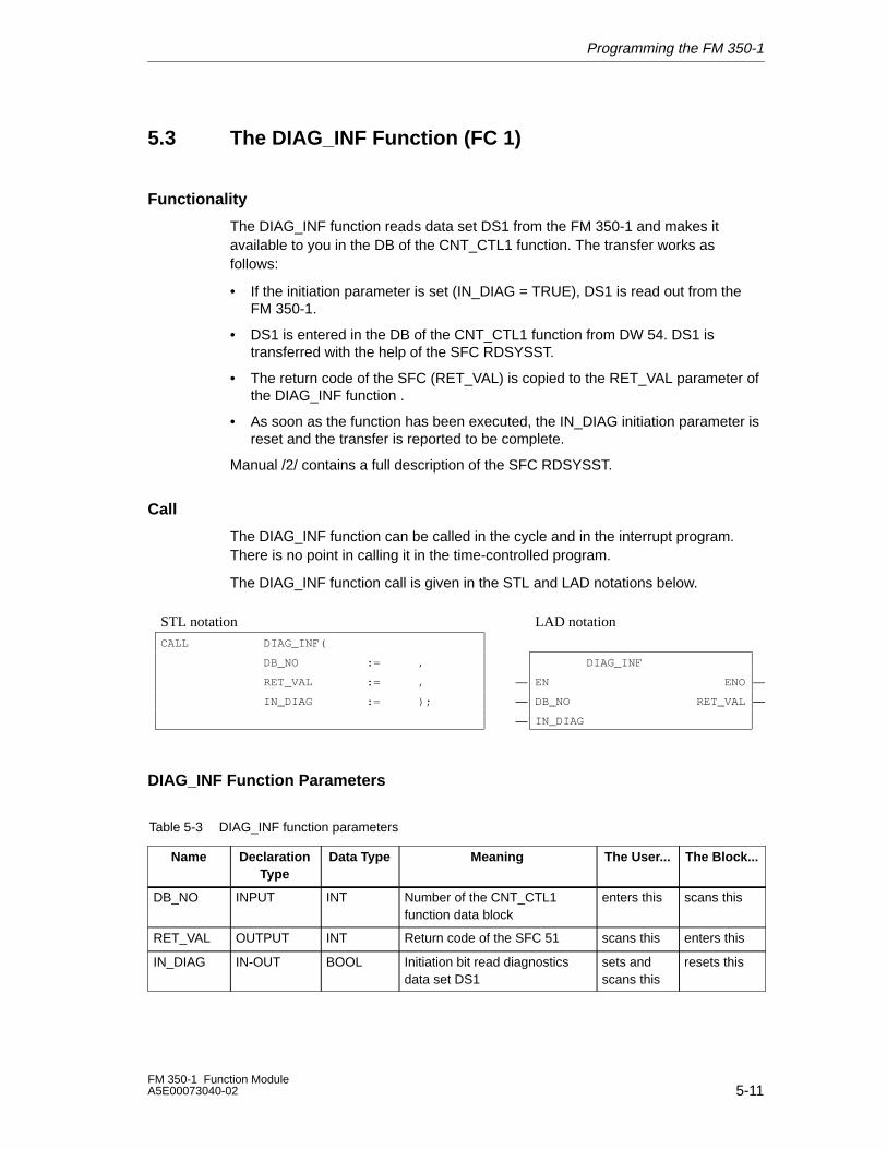
Programming the FM 350-1
5-11FM 350-1 Function ModuleA5E00073040-02
5.3 The DIAG_INF Function (FC 1)
Functionality
The DIAG_INF function reads data set DS1 from the FM 350-1 and makes itavailable to you in the DB of the CNT_CTL1 function. The transfer works asfollows:
• If the initiation parameter is set (IN_DIAG = TRUE), DS1 is read out from theFM 350-1.
• DS1 is entered in the DB of the CNT_CTL1 function from DW 54. DS1 istransferred with the help of the SFC RDSYSST.
• The return code of the SFC (RET_VAL) is copied to the RET_VAL parameter ofthe DIAG_INF function .
• As soon as the function has been executed, the IN_DIAG initiation parameter isreset and the transfer is reported to be complete.
Manual /2/ contains a full description of the SFC RDSYSST.
Call
The DIAG_INF function can be called in the cycle and in the interrupt program.There is no point in calling it in the time-controlled program.
The DIAG_INF function call is given in the STL and LAD notations below.
ÁÁÁÁÁÁÁÁÁÁÁÁÁÁÁÁÁÁÁÁÁÁÁÁÁÁÁÁÁÁÁÁÁÁ
STL notation ÁÁÁÁÁÁÁÁÁÁÁÁÁÁÁÁÁÁÁÁÁÁÁÁÁÁÁÁ
LAD notation ÁÁÁÁÁ
ÁÁÁÁÁÁÁÁÁÁÁÁÁÁÁÁÁÁÁÁÁÁÁÁÁÁÁÁÁÁÁÁÁ
CALL DIAG_INF( ÁÁÁÁÁÁÁÁÁÁÁÁÁÁÁÁÁÁÁÁÁÁÁÁÁÁÁÁ
ÁÁÁÁÁ
ÁÁÁÁÁÁÁÁÁÁÁÁÁÁÁÁÁÁÁÁÁÁÁÁÁÁÁÁÁÁÁÁÁ
DB_NO := , ÁÁÁÁÁÁÁÁÁÁÁÁÁÁÁÁÁÁÁÁÁÁÁÁÁÁÁÁ
DIAG_INF ÁÁÁÁÁ
ÁÁÁÁÁÁÁÁÁÁÁÁÁÁÁÁÁÁÁÁÁÁÁÁÁÁÁÁÁÁÁÁÁ
RET_VAL := , ÁÁÁÁÁÁ
�ÁÁÁÁÁÁÁÁÁÁÁÁÁÁÁÁÁÁÁÁÁÁ
EN ENOÁÁÁÁ�
ÁÁÁÁÁÁÁÁÁÁÁÁÁÁÁÁÁIN_DIAG := ); ÁÁÁ�ÁÁÁÁÁÁÁÁÁÁÁDB_NO RET_VALÁÁ�ÁÁÁÁÁÁÁÁÁÁÁÁÁÁÁÁÁÁÁÁÁÁÁÁÁÁÁÁÁÁÁÁÁÁ
ÁÁÁÁÁÁ�ÁÁÁÁÁÁÁÁÁÁÁÁÁÁÁÁÁÁÁÁÁÁIN_DIAG
ÁÁÁÁÁ
ÁÁÁÁÁÁÁÁÁÁÁÁÁÁÁÁÁÁÁÁÁÁÁÁÁÁÁÁÁÁÁÁÁ
ÁÁÁÁÁÁÁÁÁÁÁÁÁÁÁÁÁÁÁÁÁÁÁÁÁÁÁÁ
ÁÁÁÁ
DIAG_INF Function Parameters
Table 5-3 DIAG_INF function parameters
Name DeclarationType
Data Type Meaning The User... The Block...
DB_NO INPUT INT Number of the CNT_CTL1function data block
enters this scans this
RET_VAL OUTPUT INT Return code of the SFC 51 scans this enters this
IN_DIAG IN-OUT BOOL Initiation bit read diagnosticsdata set DS1
sets andscans this
resets this
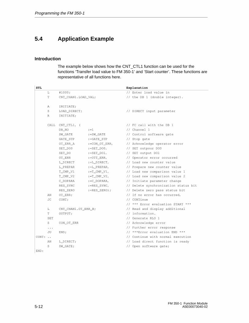
Programming the FM 350-1
5-12FM 350-1 Function Module
A5E00073040-02
5.4 Application Example
Introduction
The example below shows how the CNT_CTL1 function can be used for thefunctions ‘Transfer load value to FM 350-1’ and ‘Start counter’. These functions arerepresentative of all functions here.
STL Explanation
L #1000; // Enter load value in
T CNT_CHAN1.LOAD_VAL; // the DB 1 (double integer).
A INITIATE;
S LOAD_DIRECT; // DIRECT input parameter
R INITIATE;
CALL CNT_CTL1, ( // FC call with the DB 1
DB_NO :=1 // Channel 1
SW_GATE :=SW_GATE // Control software gate
GATE_STP :=GATE_STP // Stop gate
OT_ERR_A :=CON_OT_ERR, // Acknowledge operator error
SET_DO0 :=SET_DO0, // SET outpour DO0
SET_DO :=SET_DO1, // SET output DO1
OT_ERR :=OTT_ERR, // Operator error occurred
L_DIRECT :=L_DIRECT, // Load new counter value
L_PREPAR :=L_PREPAR, // Prepare new counter value
T_CMP_V1 :=T_CMP_V1, // Load new comparison value 1
T_CMP_V2 :=T_CMP_V2, // Load new comparison value 2
C_DOPARA :=C_DOPARA, // Initiate parameter change
RES_SYNC :=RES_SYNC, // Delete synchronization status bit
RES_ZERO :=RES_ZERO); // Delete zero pass status bit
AN OT_ERR; // If no error has occurred,
JC CONT; // CONTinue
// *** Error evaluation START ***
L CNT_CHAN1.OT_ERR_B; // Read and display additional
T OUTPUT; // information.
SET // Generate RLO 1
S CON_OT_ERR // Acknowledge error
... // Further error response
JU END; // ***Error evaluation END ***
CONT: .. // Continue with normal execution
AN L_DIRECT; // Load direct function is ready
S SW_GATE; // Open software gate;
END:
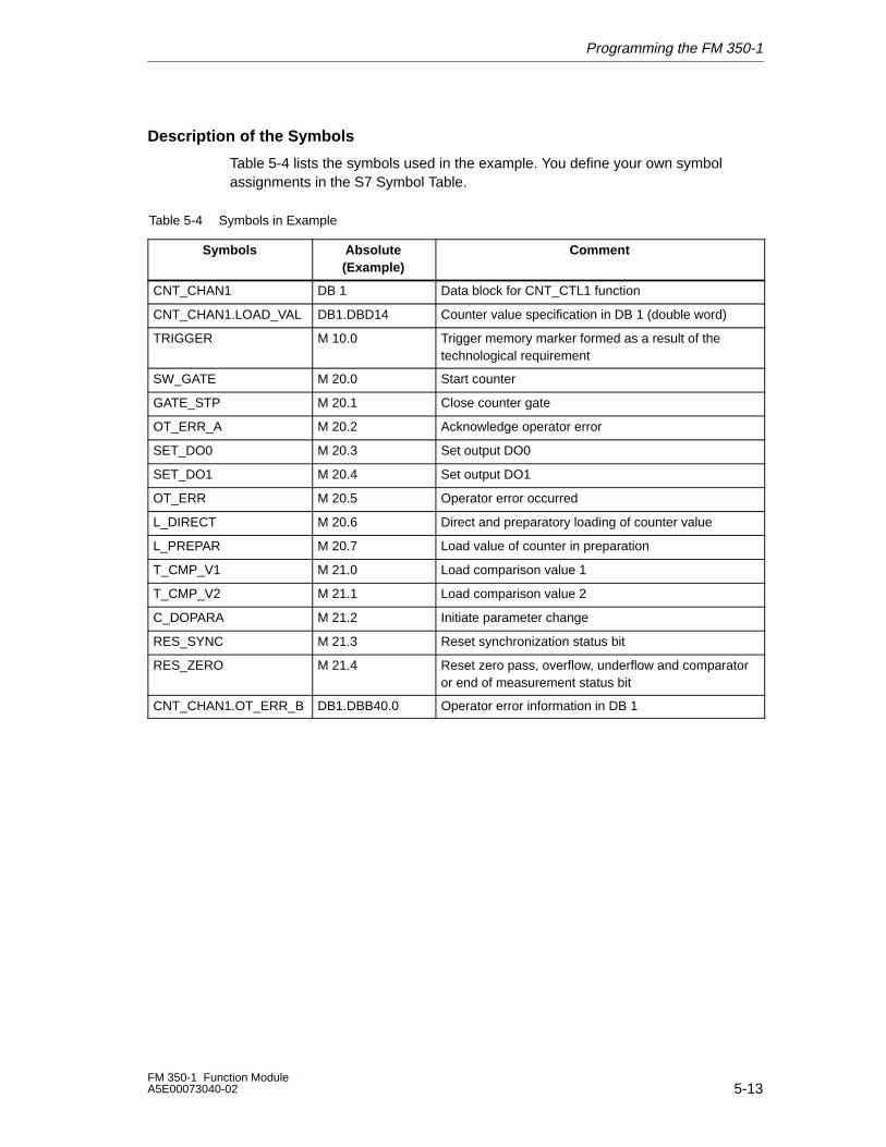
Programming the FM 350-1
5-13FM 350-1 Function ModuleA5E00073040-02
Description of the Symbols
Table 5-4 lists the symbols used in the example. You define your own symbolassignments in the S7 Symbol Table.
Table 5-4 Symbols in Example
Symbols Absolute(Example)
Comment
CNT_CHAN1 DB 1 Data block for CNT_CTL1 function
CNT_CHAN1.LOAD_VAL DB1.DBD14 Counter value specification in DB 1 (double word)
TRIGGER M 10.0 Trigger memory marker formed as a result of thetechnological requirement
SW_GATE M 20.0 Start counter
GATE_STP M 20.1 Close counter gate
OT_ERR_A M 20.2 Acknowledge operator error
SET_DO0 M 20.3 Set output DO0
SET_DO1 M 20.4 Set output DO1
OT_ERR M 20.5 Operator error occurred
L_DIRECT M 20.6 Direct and preparatory loading of counter value
L_PREPAR M 20.7 Load value of counter in preparation
T_CMP_V1 M 21.0 Load comparison value 1
T_CMP_V2 M 21.1 Load comparison value 2
C_DOPARA M 21.2 Initiate parameter change
RES_SYNC M 21.3 Reset synchronization status bit
RES_ZERO M 21.4 Reset zero pass, overflow, underflow and comparatoror end of measurement status bit
CNT_CHAN1.OT_ERR_B DB1.DBB40.0 Operator error information in DB 1
Programming the FM 350-1
5-14FM 350-1 Function Module
A5E00073040-02
Description of the Procedure
Requirement
The value to be transferred must have been entered in DB 1.
Load value is transferred and started
The load value of the channel is transferred to the FM 350-1 by means of the FCcall.
There are two parameters available for transferring the load value to the FM 350-1.When calling the CNT_CTL1 function, the parameter selected is either L_DIRECTor L_PREPAR.
Parameter L_DIRECT defines that the load value is transferred directly and inpreparation to the counter (you set the trigger bit L_DIRECT=1 in your userprogram).
Parameter L_PREPAR defines that the load value is only loaded in preparation(you have to set the trigger bit L_PREPAR=1 in your user program).
The load value loaded in preparation is then applied at the next cause that sets thecounter.
The FC must therefore be called until the FC has reset the selected trigger bit(L_DIRECT or L_PREPAR). The in/out parameter remains set during the transfer.With regard to the exchange of data with the FM, the CNT_CTL1 function does notissue an error message.
If the trigger bit you set has been reset by the CNT_CTL1 function, the FM 350-1has applied the load value. The read load value stored in DB 1 is updated by theCNT_CTL1 function (applicable only if you are working without the latch setting).
It takes at least four FC calls to transfer the load value.
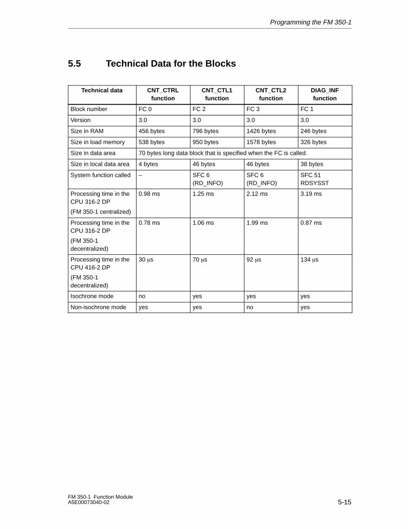
Programming the FM 350-1
5-15FM 350-1 Function ModuleA5E00073040-02
5.5 Technical Data for the Blocks
Technical data CNT_CTRLfunction
CNT_CTL1function
CNT_CTL2function
DIAG_INFfunction
Block number FC 0 FC 2 FC 3 FC 1
Version 3.0 3.0 3.0 3.0
Size in RAM 456 bytes 796 bytes 1426 bytes 246 bytes
Size in load memory 538 bytes 950 bytes 1578 bytes 326 bytes
Size in data area 70 bytes long data block that is specified when the FC is called.
Size in local data area 4 bytes 46 bytes 46 bytes 38 bytes
System function called – SFC 6(RD_INFO)
SFC 6(RD_INFO)
SFC 51RDSYSST
Processing time in theCPU 316-2 DP
(FM 350-1 centralized)
0.98 ms 1.25 ms 2.12 ms 3.19 ms
Processing time in theCPU 316-2 DP
(FM 350-1decentralized)
0.78 ms 1.06 ms 1.99 ms 0.87 ms
Processing time in theCPU 416-2 DP
(FM 350-1decentralized)
30 �s 70 �s 92 �s 134 �s
Isochrone mode no yes yes yes
Non-isochrone mode yes yes no yes
Programming the FM 350-1
5-16FM 350-1 Function Module
A5E00073040-02
5.6 Programming the FM 350-1 without FCs
If you want to operate the FM 350-1 without FCs, you can control and monitor theFM 350-1 directly via the control and check-back interface (working data interface).
The working data interface starts at the module’s starting address and is 16 byteslong.
Load commands allow you to read the check-back interface.
Transfer commands are used to write to the control interface.
Mixed use of load / transfer commands and programming with FCs is notpermitted.
5.6.1 Control and Check-back Interface for the Count Modes
Control Interface for Count Modes
The LOAD_VAL parameter (bytes 0 to 3) has two meanings:
• If you set the L_DIRECT or L_PREPAR bit, LOAD_VAL is interpreted as a loadvalue.
• If you set the C_DOPARA bit, you can use byte 0 to define the behavior ofoutputs DO0 and DO1. Bytes 1 and 2 are interpreted as hysteresis and pulseduration.
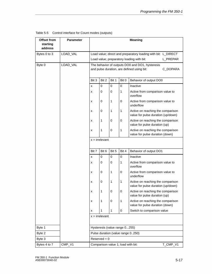
Programming the FM 350-1
5-17FM 350-1 Function ModuleA5E00073040-02
Table 5-5 Control interface for Count modes (outputs)
Offset fromstartingaddress
Parameter Meaning
Bytes 0 to 3 LOAD_VAL Load value; direct and preparatory loading with bit: L_DIRECT
Load value; preparatory loading with bit: L_PREPAR
Byte 0 LOAD_VAL The behavior of outputs DO0 and DO1, hysteresis and pulse duration, are defined using bit: C_DOPARA
Bit 3 Bit 2 Bit 1 Bit 0 Behavior of output DO0
x 0 0 0 Inactive
x 0 0 1 Active from comparison value tooverflow
x 0 1 0 Active from comparison value tounderflow
x 0 1 1 Active on reaching the comparisonvalue for pulse duration (up/down)
x 1 0 0 Active on reaching the comparisonvalue for pulse duration (up)
x 1 0 1 Active on reaching the comparisonvalue for pulse duration (down)
x = irrelevant
Bit 7 Bit 6 Bit 5 Bit 4 Behavior of output DO1
x 0 0 0 Inactive
x 0 0 1 Active from comparison value tooverflow
x 0 1 0 Active from comparison value tounderflow
x 0 1 1 Active on reaching the comparisonvalue for pulse duration (up/down)
x 1 0 0 Active on reaching the comparisonvalue for pulse duration (up)
x 1 0 1 Active on reaching the comparisonvalue for pulse duration (down)
x 1 1 0 Switch to comparison value
x = irrelevant
Byte 1 Hysteresis (value range 0...255)
Byte 2 Pulse duration (value range 0..250)
Byte 3 Reserved = 0
Bytes 4 to 7 CMP_V1 Comparison value 1; load with bit: T_CMP_V1
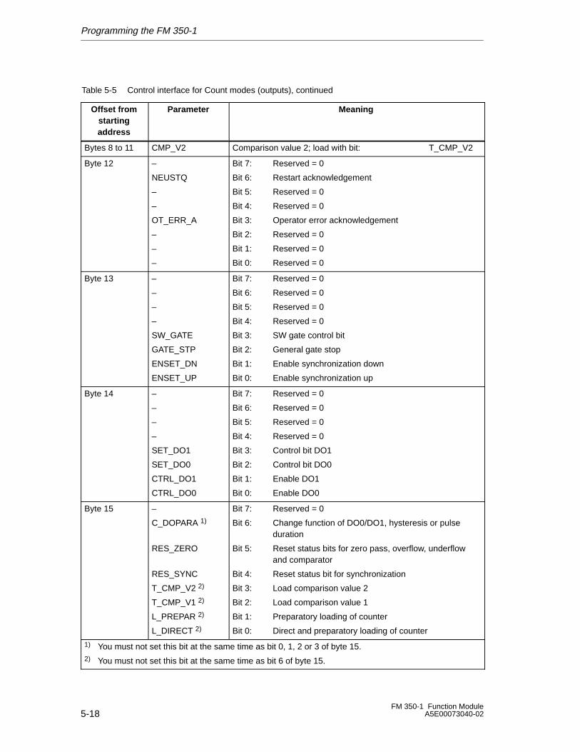
Programming the FM 350-1
5-18FM 350-1 Function Module
A5E00073040-02
Table 5-5 Control interface for Count modes (outputs), continued
Offset fromstartingaddress
MeaningParameter
Bytes 8 to 11 CMP_V2 Comparison value 2; load with bit: T_CMP_V2
Byte 12 –
NEUSTQ
–
–
OT_ERR_A
–
–
–
Bit 7: Reserved = 0
Bit 6: Restart acknowledgement
Bit 5: Reserved = 0
Bit 4: Reserved = 0
Bit 3: Operator error acknowledgement
Bit 2: Reserved = 0
Bit 1: Reserved = 0
Bit 0: Reserved = 0
Byte 13 –
–
–
–
SW_GATE
GATE_STP
ENSET_DN
ENSET_UP
Bit 7: Reserved = 0
Bit 6: Reserved = 0
Bit 5: Reserved = 0
Bit 4: Reserved = 0
Bit 3: SW gate control bit
Bit 2: General gate stop
Bit 1: Enable synchronization down
Bit 0: Enable synchronization up
Byte 14 –
–
–
–
SET_DO1
SET_DO0
CTRL_DO1
CTRL_DO0
Bit 7: Reserved = 0
Bit 6: Reserved = 0
Bit 5: Reserved = 0
Bit 4: Reserved = 0
Bit 3: Control bit DO1
Bit 2: Control bit DO0
Bit 1: Enable DO1
Bit 0: Enable DO0
Byte 15 –
C_DOPARA 1)
RES_ZERO
RES_SYNC
T_CMP_V2 2)
T_CMP_V1 2)
L_PREPAR 2)
L_DIRECT 2)
Bit 7: Reserved = 0
Bit 6: Change function of DO0/DO1, hysteresis or pulse duration
Bit 5: Reset status bits for zero pass, overflow, underflowand comparator
Bit 4: Reset status bit for synchronization
Bit 3: Load comparison value 2
Bit 2: Load comparison value 1
Bit 1: Preparatory loading of counter
Bit 0: Direct and preparatory loading of counter
1) You must not set this bit at the same time as bit 0, 1, 2 or 3 of byte 15.2) You must not set this bit at the same time as bit 6 of byte 15.
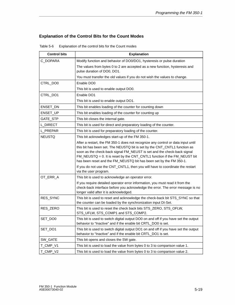
Programming the FM 350-1
5-19FM 350-1 Function ModuleA5E00073040-02
Explanation of the Control Bits for the Count Modes
Table 5-6 Explanation of the control bits for the Count modes
Control bits Explanation
C_DOPARA Modify function and behavior of DO0/DO1, hysteresis or pulse duration
The values from bytes 0 to 2 are accepted as a new function, hysteresis andpulse duration of DO0, DO1.
You must transfer the old values if you do not wish the values to change.
CTRL_DO0 Enable DO0
This bit is used to enable output DO0.
CTRL_DO1 Enable DO1
This bit is used to enable output DO1.
ENSET_DN This bit enables loading of the counter for counting down
ENSET_UP This bit enables loading of the counter for counting up
GATE_STP This bit closes the internal gate.
L_DIRECT This bit is used for direct and preparatory loading of the counter.
L_PREPAR This bit is used for preparatory loading of the counter.
NEUSTQ This bit acknowledges start-up of the FM 350-1.
After a restart, the FM 350-1 does not recognize any control or data input untilthis bit has been set. The NEUSTQ bit is set by the CNT_CNTL1 function assoon as the check-back signal FM_NEUST is set and the check-back signalFM_NEUSTQ = 0. It is reset by the CNT_CNTL1 function if the FM_NEUST bithas been reset and the FM_NEUSTQ bit has been set by the FM 350-1.
If you do not use the CNT_CNTL1, then you will have to coordinate the restartvia the user program.
OT_ERR_A This bit is used to acknowledge an operator error.
If you require detailed operator error information, you must read it from thecheck-back interface before you acknowledge the error. The error message is nolonger valid after it is acknowledged.
RES_SYNC This bit is used to reset and acknowledge the check-back bit STS_SYNC so thatthe counter can be loaded by the synchronization input DI-Set.
RES_ZERO This bit is used to reset the check back bits STS_ZERO, STS_OFLW,STS_UFLW, STS_COMP1 and STS_COMP2.
SET_DO0 This bit is used to switch digital output DO0 on and off if you have set the outputbehavior to “Inactive” and if the enable bit CRTL_DO0 is set.
SET_DO1 This bit is used to switch digital output DO1 on and off if you have set the outputbehavior to “Inactive” and if the enable bit CRTL_DO1 is set.
SW_GATE This bit opens and closes the SW gate.
T_CMP_V1 This bit is used to load the value from bytes 0 to 3 to comparison value 1.
T_CMP_V2 This bit is used to load the value from bytes 0 to 3 to comparison value 2.
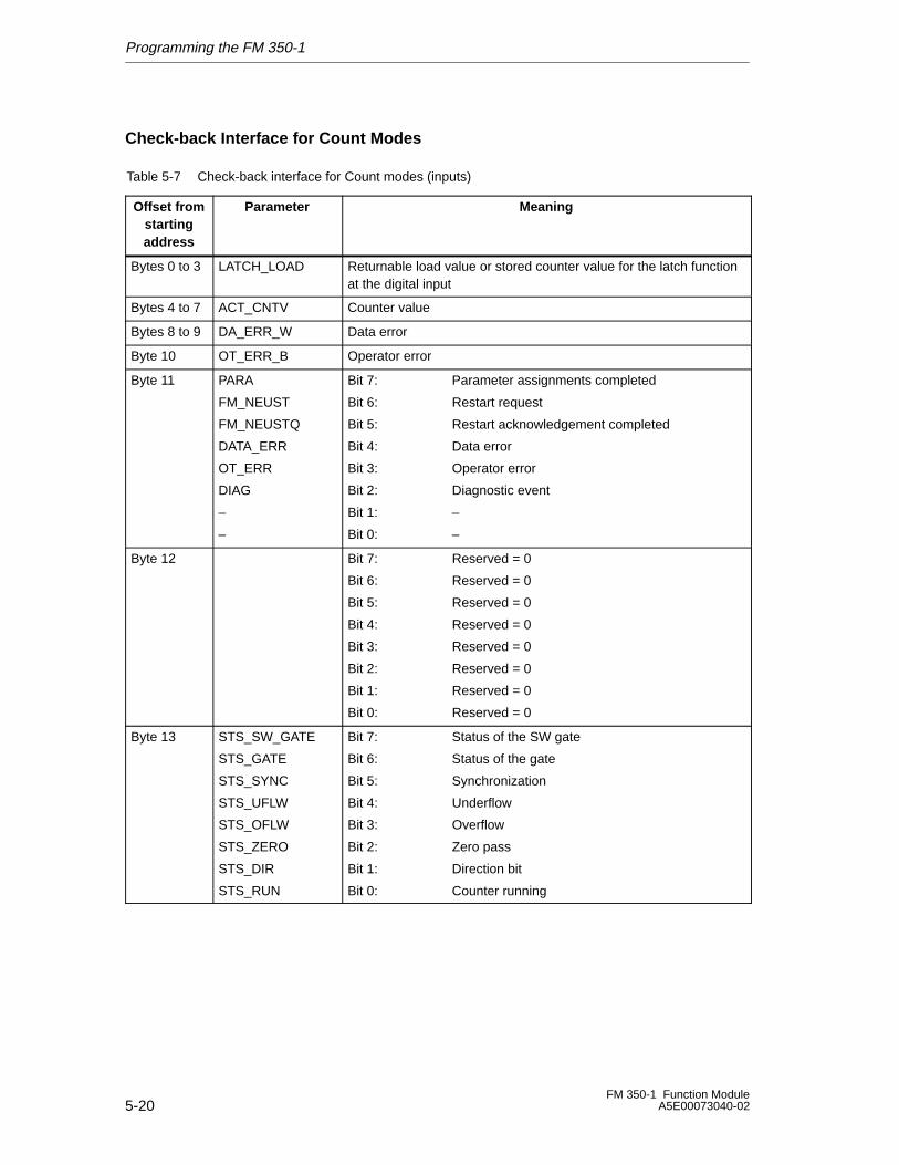
Programming the FM 350-1
5-20FM 350-1 Function Module
A5E00073040-02
Check-back Interface for Count Modes
Table 5-7 Check-back interface for Count modes (inputs)
Offset fromstartingaddress
Parameter Meaning
Bytes 0 to 3 LATCH_LOAD Returnable load value or stored counter value for the latch functionat the digital input
Bytes 4 to 7 ACT_CNTV Counter value
Bytes 8 to 9 DA_ERR_W Data error
Byte 10 OT_ERR_B Operator error
Byte 11 PARA
FM_NEUST
FM_NEUSTQ
DATA_ERR
OT_ERR
DIAG
–
–
Bit 7: Parameter assignments completed
Bit 6: Restart request
Bit 5: Restart acknowledgement completed
Bit 4: Data error
Bit 3: Operator error
Bit 2: Diagnostic event
Bit 1: –
Bit 0: –
Byte 12 Bit 7: Reserved = 0
Bit 6: Reserved = 0
Bit 5: Reserved = 0
Bit 4: Reserved = 0
Bit 3: Reserved = 0
Bit 2: Reserved = 0
Bit 1: Reserved = 0
Bit 0: Reserved = 0
Byte 13 STS_SW_GATE
STS_GATE
STS_SYNC
STS_UFLW
STS_OFLW
STS_ZERO
STS_DIR
STS_RUN
Bit 7: Status of the SW gate
Bit 6: Status of the gate
Bit 5: Synchronization
Bit 4: Underflow
Bit 3: Overflow
Bit 2: Zero pass
Bit 1: Direction bit
Bit 0: Counter running
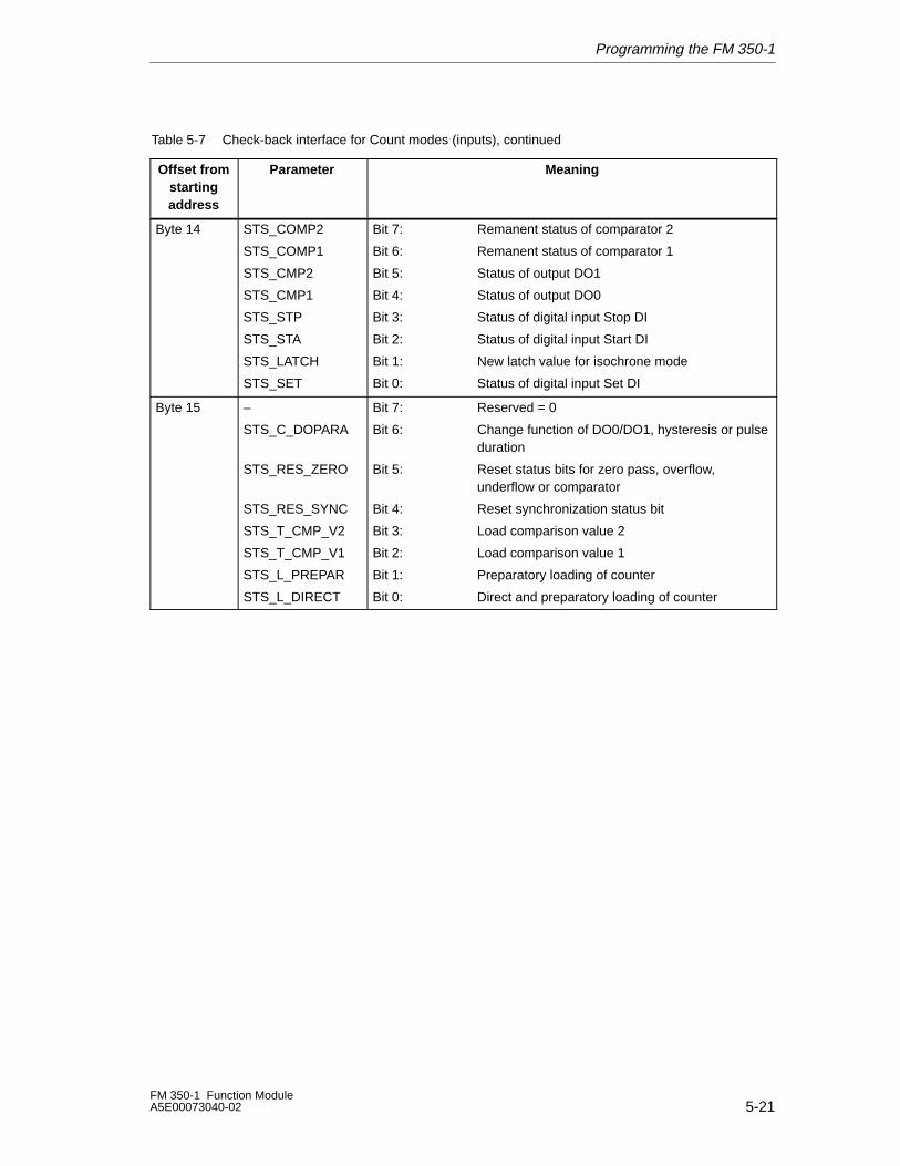
Programming the FM 350-1
5-21FM 350-1 Function ModuleA5E00073040-02
Table 5-7 Check-back interface for Count modes (inputs), continued
Offset fromstartingaddress
MeaningParameter
Byte 14 STS_COMP2
STS_COMP1
STS_CMP2
STS_CMP1
STS_STP
STS_STA
STS_LATCH
STS_SET
Bit 7: Remanent status of comparator 2
Bit 6: Remanent status of comparator 1
Bit 5: Status of output DO1
Bit 4: Status of output DO0
Bit 3: Status of digital input Stop DI
Bit 2: Status of digital input Start DI
Bit 1: New latch value for isochrone mode
Bit 0: Status of digital input Set DI
Byte 15 –
STS_C_DOPARA
STS_RES_ZERO
STS_RES_SYNC
STS_T_CMP_V2
STS_T_CMP_V1
STS_L_PREPAR
STS_L_DIRECT
Bit 7: Reserved = 0
Bit 6: Change function of DO0/DO1, hysteresis or pulseduration
Bit 5: Reset status bits for zero pass, overflow, underflow or comparator
Bit 4: Reset synchronization status bit
Bit 3: Load comparison value 2
Bit 2: Load comparison value 1
Bit 1: Preparatory loading of counter
Bit 0: Direct and preparatory loading of counter
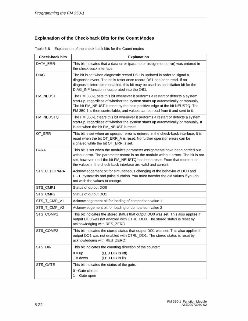
Programming the FM 350-1
5-22FM 350-1 Function Module
A5E00073040-02
Explanation of the Check-back Bits for the Count Modes
Table 5-8 Explanation of the check-back bits for the Count modes
Check-back bits Explanation
DATA_ERR This bit indicates that a data error (parameter assignment error) was entered inthe check-back interface.
DIAG The bit is set when diagnostic record DS1 is updated in order to signal adiagnostic event. The bit is reset once record DS1 has been read. If nodiagnostic interrupt is enabled, this bit may be used as an initiation bit for theDIAG_INF function incorporated into the OB1.
FM_NEUST The FM 350-1 sets this bit whenever it performs a restart or detects a systemstart-up, regardless of whether the system starts up automatically or manually.The bit FM_NEUST is reset by the next positive edge at the bit NEUSTQ. TheFM 350-1 is then controllable, and values can be read from it and sent to it.
FM_NEUSTQ The FM 350-1 clears this bit whenever it performs a restart or detects a systemstart-up, regardless of whether the system starts up automatically or manually. Itis set when the bit FM_NEUST is reset.
OT_ERR This bit is set when an operator error is entered in the check-back interface. It isreset when the bit OT_ERR_A is reset. No further operator errors can besignaled while the bit OT_ERR is set.
PARA This bit is set when the module’s parameter assignments have been carried outwithout error. The parameter record is on the module without errors. The bit is notset, however, until the bit FM_NEUSTQ has been reset. From that moment on,the values in the check-back interface are valid and current.
STS_C_DOPARA Acknowledgement bit for simultaneous changing of the behavior of DO0 andDO1, hysteresis and pulse duration. You must transfer the old values if you donot wish the values to change.
STS_CMP1 Status of output DO0
STS_CMP2 Status of output DO1
STS_T_CMP_V1 Acknowledgement bit for loading of comparison value 1
STS_T_CMP_V2 Acknowledgement bit for loading of comparison value 2
STS_COMP1 This bit indicates the stored status that output DO0 was set. This also applies ifoutput DO0 was not enabled with CTRL_DO0. The stored status is reset byacknowledging with RES_ZERO.
STS_COMP2 This bit indicates the stored status that output DO1 was set. This also applies ifoutput DO1 was not enabled with CTRL_DO1. The stored status is reset byacknowledging with RES_ZERO.
STS_DIR This bit indicates the counting direction of the counter:
0 = up (LED DIR is off) 1 = down (LED DIR is lit)
STS_GATE This bit indicates the status of the gate.
0 =Gate closed1 = Gate open
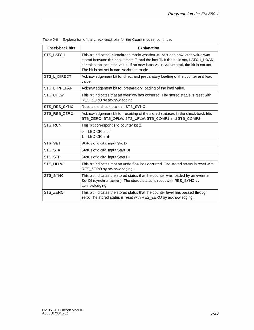
Programming the FM 350-1
5-23FM 350-1 Function ModuleA5E00073040-02
Table 5-8 Explanation of the check-back bits for the Count modes, continued
Check-back bits Explanation
STS_LATCH This bit indicates in isochrone mode whether at least one new latch value wasstored between the penultimate Ti and the last Ti. If the bit is set, LATCH_LOADcontains the last latch value. If no new latch value was stored, the bit is not set.The bit is not set in non-isochrone mode.
STS_L_DIRECT Acknowledgement bit for direct and preparatory loading of the counter and loadvalue.
STS_L_PREPAR Acknowledgement bit for preparatory loading of the load value.
STS_OFLW This bit indicates that an overflow has occurred. The stored status is reset withRES_ZERO by acknowledging.
STS_RES_SYNC Resets the check-back bit STS_SYNC.
STS_RES_ZERO Acknowledgement bit for resetting of the stored statuses in the check-back bitsSTS_ZERO, STS_OFLW, STS_UFLW, STS_COMP1 and STS_COMP2
STS_RUN This bit corresponds to counter bit 2.
0 = LED CR is off 1 = LED CR is lit
STS_SET Status of digital input Set DI
STS_STA Status of digital input Start DI
STS_STP Status of digital input Stop DI
STS_UFLW This bit indicates that an underflow has occurred. The stored status is reset withRES_ZERO by acknowledging.
STS_SYNC This bit indicates the stored status that the counter was loaded by an event atSet DI (synchronization). The stored status is reset with RES_SYNC byacknowledging.
STS_ZERO This bit indicates the stored status that the counter level has passed throughzero. The stored status is reset with RES_ZERO by acknowledging.
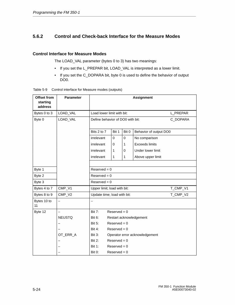
Programming the FM 350-1
5-24FM 350-1 Function Module
A5E00073040-02
5.6.2 Control and Check-back Interface for the Measure Modes
Control Interface for Measure Modes
The LOAD_VAL parameter (bytes 0 to 3) has two meanings:
• If you set the L_PREPAR bit, LOAD_VAL is interpreted as a lower limit.
• If you set the C_DOPARA bit, byte 0 is used to define the behavior of outputDO0.
Table 5-9 Control interface for Measure modes (outputs)
Offset fromstartingaddress
Parameter Assignment
Bytes 0 to 3 LOAD_VAL Load lower limit with bit: L_PREPAR
Byte 0 LOAD_VAL Define behavior of DO0 with bit: C_DOPARA
Bits 2 to 7 Bit 1 Bit 0 Behavior of output DO0
irrelevant 0 0 No comparison
irrelevant 0 1 Exceeds limits
irrelevant 1 0 Under lower limit
irrelevant 1 1 Above upper limit
Byte 1 Reserved = 0
Byte 2 Reserved = 0
Byte 3 Reserved = 0
Bytes 4 to 7 CMP_V1 Upper limit; load with bit: T_CMP_V1
Bytes 8 to 9 CMP_V2 Update time; load with bit: T_CMP_V2
Bytes 10 to11
– –
Byte 12 –
NEUSTQ
–
–
OT_ERR_A
–
–
–
Bit 7: Reserved = 0
Bit 6: Restart acknowledgement
Bit 5: Reserved = 0
Bit 4: Reserved = 0
Bit 3: Operator error acknowledgement
Bit 2: Reserved = 0
Bit 1: Reserved = 0
Bit 0: Reserved = 0
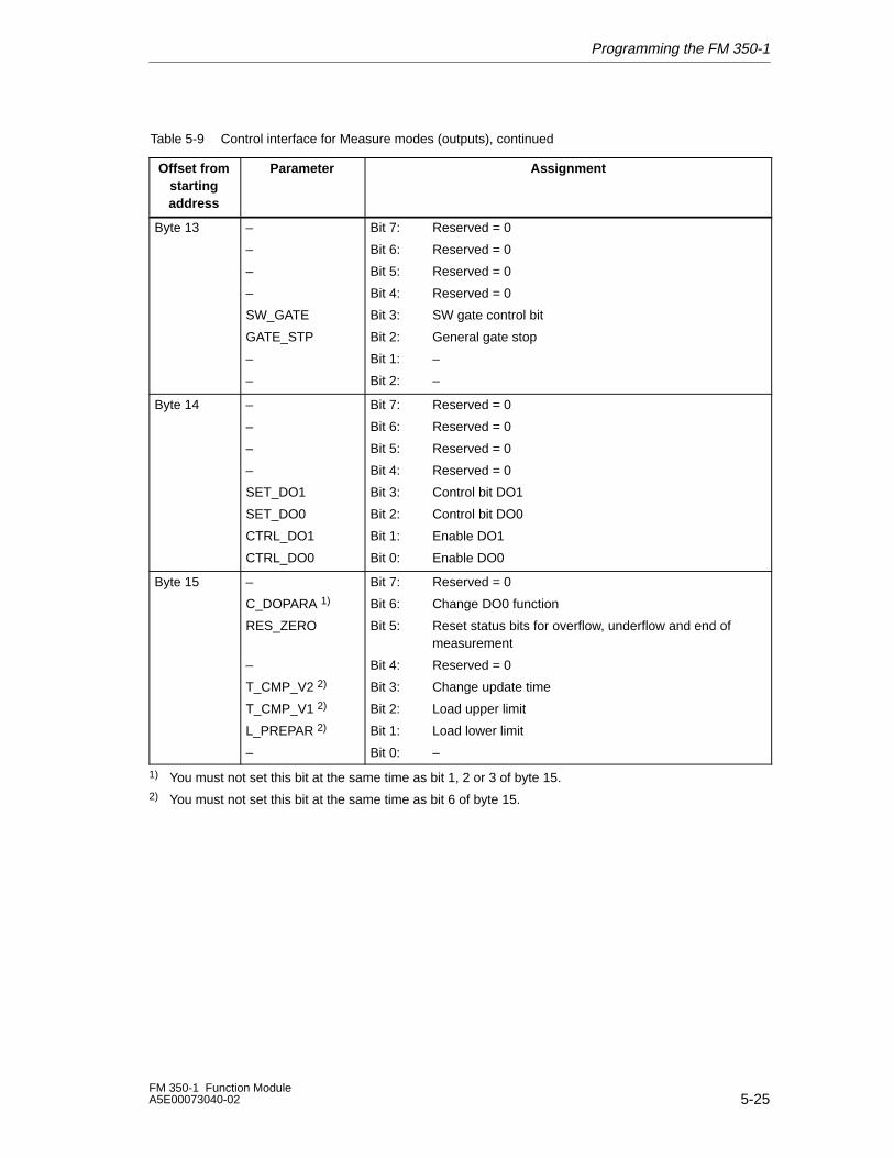
Programming the FM 350-1
5-25FM 350-1 Function ModuleA5E00073040-02
Table 5-9 Control interface for Measure modes (outputs), continued
Offset fromstartingaddress
AssignmentParameter
Byte 13 –
–
–
–
SW_GATE
GATE_STP
–
–
Bit 7: Reserved = 0
Bit 6: Reserved = 0
Bit 5: Reserved = 0
Bit 4: Reserved = 0
Bit 3: SW gate control bit
Bit 2: General gate stop
Bit 1: –
Bit 2: –
Byte 14 –
–
–
–
SET_DO1
SET_DO0
CTRL_DO1
CTRL_DO0
Bit 7: Reserved = 0
Bit 6: Reserved = 0
Bit 5: Reserved = 0
Bit 4: Reserved = 0
Bit 3: Control bit DO1
Bit 2: Control bit DO0
Bit 1: Enable DO1
Bit 0: Enable DO0
Byte 15 –
C_DOPARA 1)
RES_ZERO
–
T_CMP_V2 2)
T_CMP_V1 2)
L_PREPAR 2)
–
Bit 7: Reserved = 0
Bit 6: Change DO0 function
Bit 5: Reset status bits for overflow, underflow and end of measurement
Bit 4: Reserved = 0
Bit 3: Change update time
Bit 2: Load upper limit
Bit 1: Load lower limit
Bit 0: –
1) You must not set this bit at the same time as bit 1, 2 or 3 of byte 15.2) You must not set this bit at the same time as bit 6 of byte 15.
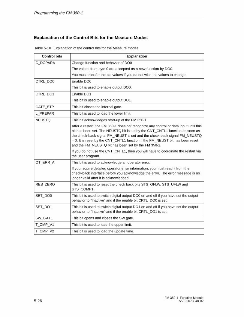
Programming the FM 350-1
5-26FM 350-1 Function Module
A5E00073040-02
Explanation of the Control Bits for the Measure Modes
Table 5-10 Explanation of the control bits for the Measure modes
Control bits Explanation
C_DOPARA Change function and behavior of DO0
The values from byte 0 are accepted as a new function by DO0.
You must transfer the old values if you do not wish the values to change.
CTRL_DO0 Enable DO0
This bit is used to enable output DO0.
CTRL_DO1 Enable DO1
This bit is used to enable output DO1.
GATE_STP This bit closes the internal gate.
L_PREPAR This bit is used to load the lower limit.
NEUSTQ This bit acknowledges start-up of the FM 350-1.
After a restart, the FM 350-1 does not recognize any control or data input until thisbit has been set. The NEUSTQ bit is set by the CNT_CNTL1 function as soon asthe check-back signal FM_NEUST is set and the check-back signal FM_NEUSTQ= 0. It is reset by the CNT_CNTL1 function if the FM_NEUST bit has been resetand the FM_NEUSTQ bit has been set by the FM 350-1.
If you do not use the CNT_CNTL1, then you will have to coordinate the restart viathe user program.
OT_ERR_A This bit is used to acknowledge an operator error.
If you require detailed operator error information, you must read it from thecheck-back interface before you acknowledge the error. The error message is nolonger valid after it is acknowledged.
RES_ZERO This bit is used to reset the check back bits STS_OFLW, STS_UFLW andSTS_COMP1.
SET_DO0 This bit is used to switch digital output DO0 on and off if you have set the outputbehavior to “Inactive” and if the enable bit CRTL_DO0 is set.
SET_DO1 This bit is used to switch digital output DO1 on and off if you have set the outputbehavior to “Inactive” and if the enable bit CRTL_DO1 is set.
SW_GATE This bit opens and closes the SW gate.
T_CMP_V1 This bit is used to load the upper limit.
T_CMP_V2 This bit is used to load the update time.
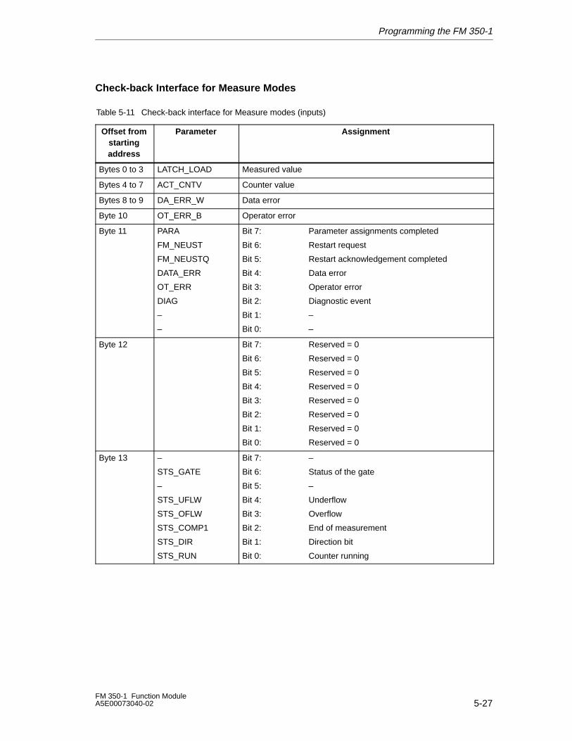
Programming the FM 350-1
5-27FM 350-1 Function ModuleA5E00073040-02
Check-back Interface for Measure Modes
Table 5-11 Check-back interface for Measure modes (inputs)
Offset fromstartingaddress
Parameter Assignment
Bytes 0 to 3 LATCH_LOAD Measured value
Bytes 4 to 7 ACT_CNTV Counter value
Bytes 8 to 9 DA_ERR_W Data error
Byte 10 OT_ERR_B Operator error
Byte 11 PARA
FM_NEUST
FM_NEUSTQ
DATA_ERR
OT_ERR
DIAG
–
–
Bit 7: Parameter assignments completed
Bit 6: Restart request
Bit 5: Restart acknowledgement completed
Bit 4: Data error
Bit 3: Operator error
Bit 2: Diagnostic event
Bit 1: –
Bit 0: –
Byte 12 Bit 7: Reserved = 0
Bit 6: Reserved = 0
Bit 5: Reserved = 0
Bit 4: Reserved = 0
Bit 3: Reserved = 0
Bit 2: Reserved = 0
Bit 1: Reserved = 0
Bit 0: Reserved = 0
Byte 13 –
STS_GATE
–
STS_UFLW
STS_OFLW
STS_COMP1
STS_DIR
STS_RUN
Bit 7: –
Bit 6: Status of the gate
Bit 5: –
Bit 4: Underflow
Bit 3: Overflow
Bit 2: End of measurement
Bit 1: Direction bit
Bit 0: Counter running
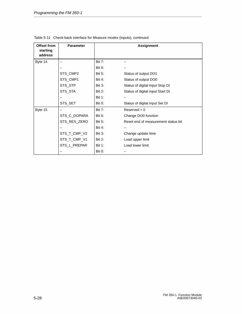
Programming the FM 350-1
5-28FM 350-1 Function Module
A5E00073040-02
Table 5-11 Check-back interface for Measure modes (inputs), continued
Offset fromstartingaddress
AssignmentParameter
Byte 14 –
–
STS_CMP2
STS_CMP1
STS_STP
STS_STA
–
STS_SET
Bit 7: –
Bit 6: –
Bit 5: Status of output DO1
Bit 4: Status of output DO0
Bit 3: Status of digital input Stop DI
Bit 2: Status of digital input Start DI
Bit 1: –
Bit 0: Status of digital input Set DI
Byte 15 –
STS_C_DOPARA
STS_RES_ZERO
–
STS_T_CMP_V2
STS_T_CMP_V1
STS_L_PREPAR
–
Bit 7: Reserved = 0
Bit 6: Change DO0 function
Bit 5: Reset end of measurement status bit
Bit 4: –
Bit 3: Change update time
Bit 2: Load upper limit
Bit 1: Load lower limit
Bit 0: –
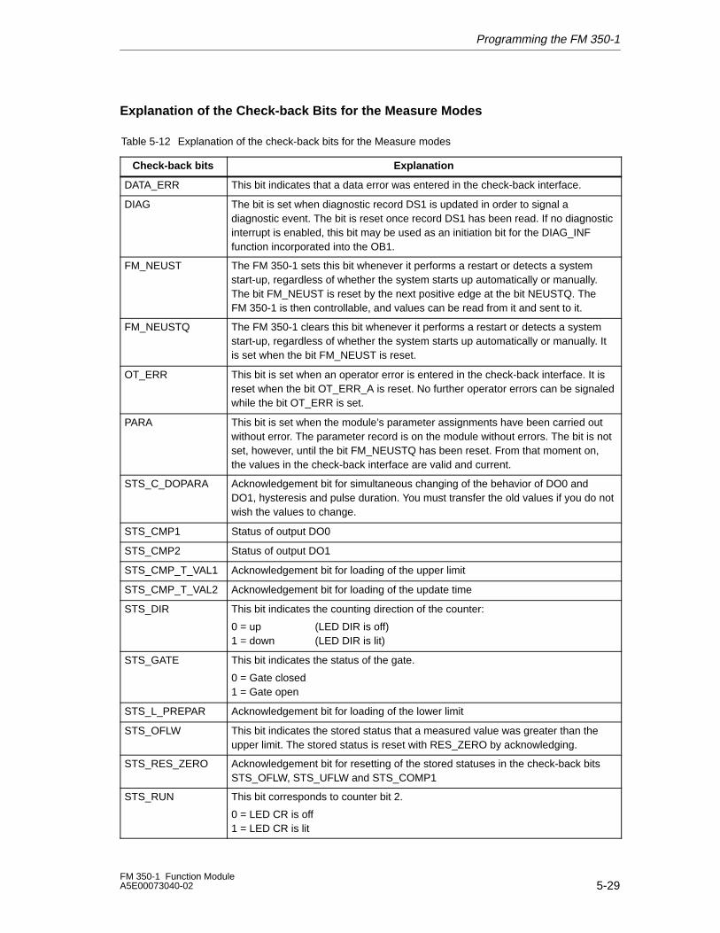
Programming the FM 350-1
5-29FM 350-1 Function ModuleA5E00073040-02
Explanation of the Check-back Bits for the Measure Modes
Table 5-12 Explanation of the check-back bits for the Measure modes
Check-back bits Explanation
DATA_ERR This bit indicates that a data error was entered in the check-back interface.
DIAG The bit is set when diagnostic record DS1 is updated in order to signal adiagnostic event. The bit is reset once record DS1 has been read. If no diagnosticinterrupt is enabled, this bit may be used as an initiation bit for the DIAG_INFfunction incorporated into the OB1.
FM_NEUST The FM 350-1 sets this bit whenever it performs a restart or detects a systemstart-up, regardless of whether the system starts up automatically or manually.The bit FM_NEUST is reset by the next positive edge at the bit NEUSTQ. TheFM 350-1 is then controllable, and values can be read from it and sent to it.
FM_NEUSTQ The FM 350-1 clears this bit whenever it performs a restart or detects a systemstart-up, regardless of whether the system starts up automatically or manually. Itis set when the bit FM_NEUST is reset.
OT_ERR This bit is set when an operator error is entered in the check-back interface. It isreset when the bit OT_ERR_A is reset. No further operator errors can be signaledwhile the bit OT_ERR is set.
PARA This bit is set when the module’s parameter assignments have been carried outwithout error. The parameter record is on the module without errors. The bit is notset, however, until the bit FM_NEUSTQ has been reset. From that moment on,the values in the check-back interface are valid and current.
STS_C_DOPARA Acknowledgement bit for simultaneous changing of the behavior of DO0 andDO1, hysteresis and pulse duration. You must transfer the old values if you do notwish the values to change.
STS_CMP1 Status of output DO0
STS_CMP2 Status of output DO1
STS_CMP_T_VAL1 Acknowledgement bit for loading of the upper limit
STS_CMP_T_VAL2 Acknowledgement bit for loading of the update time
STS_DIR This bit indicates the counting direction of the counter:
0 = up (LED DIR is off) 1 = down (LED DIR is lit)
STS_GATE This bit indicates the status of the gate.
0 = Gate closed 1 = Gate open
STS_L_PREPAR Acknowledgement bit for loading of the lower limit
STS_OFLW This bit indicates the stored status that a measured value was greater than theupper limit. The stored status is reset with RES_ZERO by acknowledging.
STS_RES_ZERO Acknowledgement bit for resetting of the stored statuses in the check-back bitsSTS_OFLW, STS_UFLW and STS_COMP1
STS_RUN This bit corresponds to counter bit 2.
0 = LED CR is off 1 = LED CR is lit
Programming the FM 350-1
5-30FM 350-1 Function Module
A5E00073040-02
Table 5-12 Explanation of the check-back bits for the Measure modes, continued
Check-back bits Explanation
STS_SET Status of digital input Set DI
STS_STA Status of digital input Start DI
STS_STP Status of digital input Stop DI
STS_UFLW This bit indicates the stored status that a measured value was less than the lowerlimit. The stored status is reset with RES_ZERO by acknowledging.
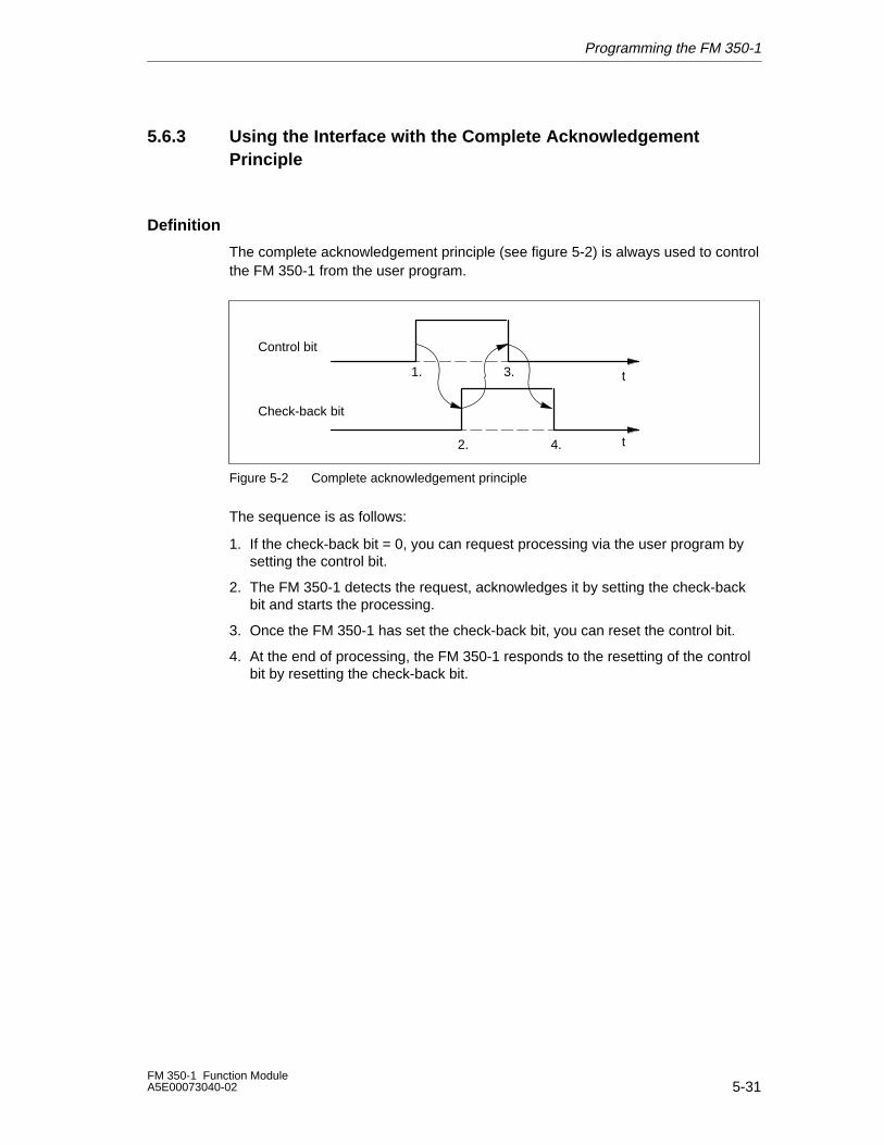
Programming the FM 350-1
5-31FM 350-1 Function ModuleA5E00073040-02
5.6.3 Using the Interface with the Complete AcknowledgementPrinciple
Definition
The complete acknowledgement principle (see figure 5-2) is always used to controlthe FM 350-1 from the user program.
t
Control bit
Check-back bit
t1.
2.
3.
4.
Figure 5-2 Complete acknowledgement principle
The sequence is as follows:
1. If the check-back bit = 0, you can request processing via the user program bysetting the control bit.
2. The FM 350-1 detects the request, acknowledges it by setting the check-backbit and starts the processing.
3. Once the FM 350-1 has set the check-back bit, you can reset the control bit.
4. At the end of processing, the FM 350-1 responds to the resetting of the controlbit by resetting the check-back bit.
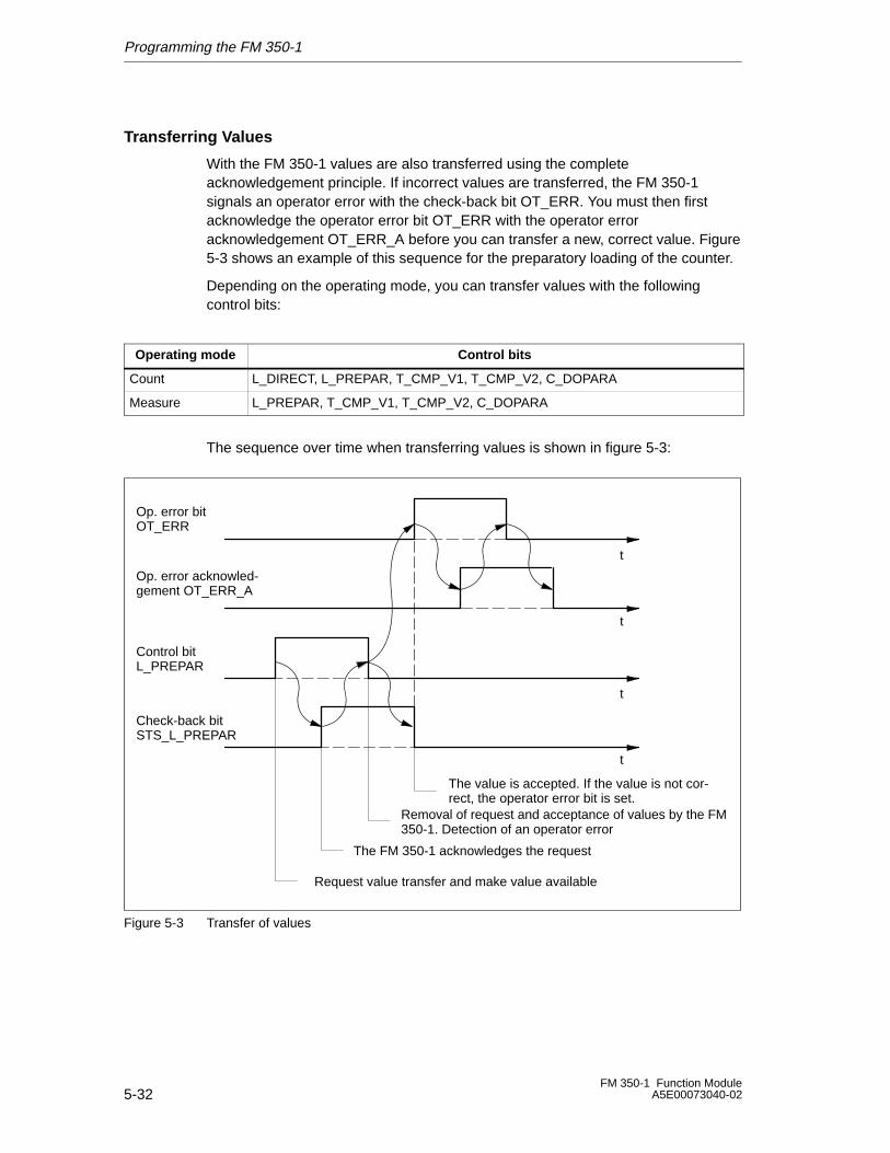
Programming the FM 350-1
5-32FM 350-1 Function Module
A5E00073040-02
Transferring Values
With the FM 350-1 values are also transferred using the completeacknowledgement principle. If incorrect values are transferred, the FM 350-1signals an operator error with the check-back bit OT_ERR. You must then firstacknowledge the operator error bit OT_ERR with the operator erroracknowledgement OT_ERR_A before you can transfer a new, correct value. Figure5-3 shows an example of this sequence for the preparatory loading of the counter.
Depending on the operating mode, you can transfer values with the followingcontrol bits:
Operating mode Control bits
Count L_DIRECT, L_PREPAR, T_CMP_V1, T_CMP_V2, C_DOPARA
Measure L_PREPAR, T_CMP_V1, T_CMP_V2, C_DOPARA
The sequence over time when transferring values is shown in figure 5-3:
t
Control bitL_PREPAR
Check-back bitSTS_L_PREPAR
t
Request value transfer and make value available
The FM 350-1 acknowledges the request
Removal of request and acceptance of values by the FM350-1. Detection of an operator error
The value is accepted. If the value is not cor-rect, the operator error bit is set.
Op. error bitOT_ERR
t
t
Op. error acknowled-gement OT_ERR_A
Figure 5-3 Transfer of values
Programming the FM 350-1
5-33FM 350-1 Function ModuleA5E00073040-02
You can transfer several values at the same time:
In … ... you can transfer at the same time
Count • Load value
• Comparison value 1
• Comparison value 2
(Parameter LOAD_VAL)
(parameter CMP_V1)
(Parameter CMP_V2)
Measure • Lower limit
• Upper limit
• Update time
(Parameter LOAD_VAL)
(parameter CMP_V1)
(Parameter CMP_V2)
If a value is incorrect, you must first acknowledge this operator error withOT_ERR_A before the FM 350-1 can accept any further values. You should thencorrect the value rejected with the operator error and transfer it again.
Note
If you use the control bits L_DIRECT, L_PREPAR, T_CMP_V1 or T_CMP_V2 toload the value LOAD_VAL, CMP_V1 or CMP_V2, you cannot change theparameter assignments at the same time using the C_DOPARA control bit.
This would lead to an OT_ERR operator error that you would have to acknowledgewith OT_ERR_A.
Time Required to Transfer Values
The time required to transfer values is shown in the table below:
Use of the FM 350-1 Time required
Centralized At least 3 OB 1 cycles
Decentralized (non-isochrone mode) At least 4 PROFIBUS DP cycles
Decentralized (isochrone mode)
• Transfer of just one value 4 PROFIBUS DP cycles
• If the transfer of several values isinitiated at the same time the valuesbelow reach FM 350-1
– the 1st value: 4 PROFIBUS DP cycles after initiation
– the 2nd value: 5 PROFIBUS DP cycles after initiation
– the 3rd value: 6 PROFIBUS DP cycles after initiation
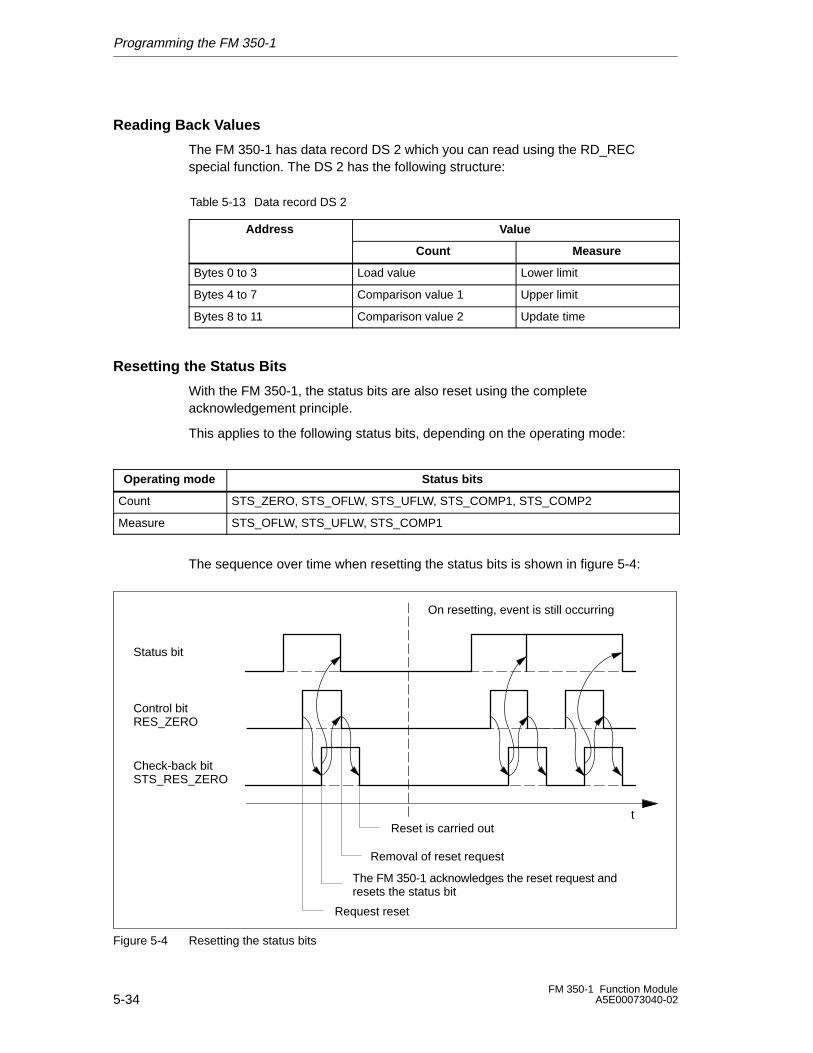
Programming the FM 350-1
5-34FM 350-1 Function Module
A5E00073040-02
Reading Back Values
The FM 350-1 has data record DS 2 which you can read using the RD_RECspecial function. The DS 2 has the following structure:
Table 5-13 Data record DS 2
Address Value
Count Measure
Bytes 0 to 3 Load value Lower limit
Bytes 4 to 7 Comparison value 1 Upper limit
Bytes 8 to 11 Comparison value 2 Update time
Resetting the Status Bits
With the FM 350-1, the status bits are also reset using the completeacknowledgement principle.
This applies to the following status bits, depending on the operating mode:
Operating mode Status bits
Count STS_ZERO, STS_OFLW, STS_UFLW, STS_COMP1, STS_COMP2
Measure STS_OFLW, STS_UFLW, STS_COMP1
The sequence over time when resetting the status bits is shown in figure 5-4:
Status bit
t
Control bitRES_ZERO
Check-back bitSTS_RES_ZERO
On resetting, event is still occurring
Request reset
The FM 350-1 acknowledges the reset request andresets the status bit
Removal of reset request
Reset is carried out
Figure 5-4 Resetting the status bits
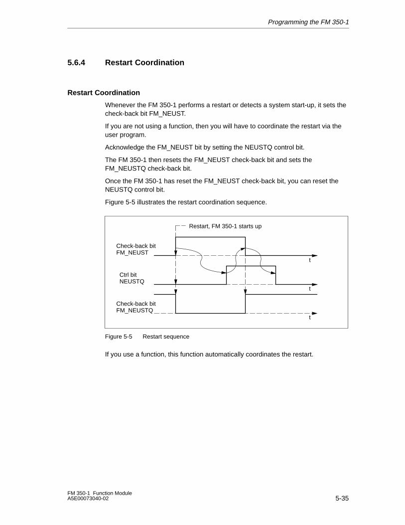
Programming the FM 350-1
5-35FM 350-1 Function ModuleA5E00073040-02
5.6.4 Restart Coordination
Restart Coordination
Whenever the FM 350-1 performs a restart or detects a system start-up, it sets thecheck-back bit FM_NEUST.
If you are not using a function, then you will have to coordinate the restart via theuser program.
Acknowledge the FM_NEUST bit by setting the NEUSTQ control bit.
The FM 350-1 then resets the FM_NEUST check-back bit and sets theFM_NEUSTQ check-back bit.
Once the FM 350-1 has reset the FM_NEUST check-back bit, you can reset theNEUSTQ control bit.
Figure 5-5 illustrates the restart coordination sequence.
Check-back bitFM_NEUST
Check-back bitFM_NEUSTQ
t
Ctrl bitNEUSTQ
Restart, FM 350-1 starts up
t
t
Figure 5-5 Restart sequence
If you use a function, this function automatically coordinates the restart.
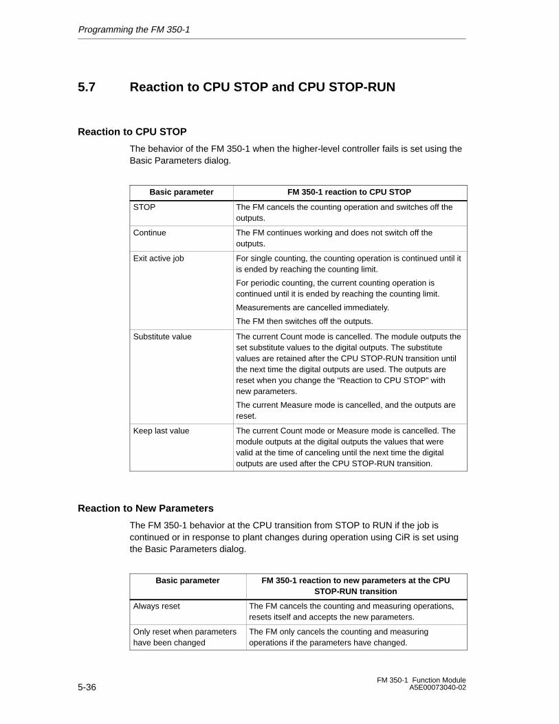
Programming the FM 350-1
5-36FM 350-1 Function Module
A5E00073040-02
5.7 Reaction to CPU STOP and CPU STOP-RUN
Reaction to CPU STOP
The behavior of the FM 350-1 when the higher-level controller fails is set using theBasic Parameters dialog.
Basic parameter FM 350-1 reaction to CPU STOP
STOP The FM cancels the counting operation and switches off theoutputs.
Continue The FM continues working and does not switch off theoutputs.
Exit active job For single counting, the counting operation is continued until itis ended by reaching the counting limit.
For periodic counting, the current counting operation iscontinued until it is ended by reaching the counting limit.
Measurements are cancelled immediately.
The FM then switches off the outputs.
Substitute value The current Count mode is cancelled. The module outputs theset substitute values to the digital outputs. The substitutevalues are retained after the CPU STOP-RUN transition untilthe next time the digital outputs are used. The outputs arereset when you change the “Reaction to CPU STOP” withnew parameters.
The current Measure mode is cancelled, and the outputs arereset.
Keep last value The current Count mode or Measure mode is cancelled. Themodule outputs at the digital outputs the values that werevalid at the time of canceling until the next time the digitaloutputs are used after the CPU STOP-RUN transition.
Reaction to New Parameters
The FM 350-1 behavior at the CPU transition from STOP to RUN if the job iscontinued or in response to plant changes during operation using CiR is set usingthe Basic Parameters dialog.
Basic parameter FM 350-1 reaction to new parameters at the CPUSTOP-RUN transition
Always reset The FM cancels the counting and measuring operations,resets itself and accepts the new parameters.
Only reset when parametershave been changed
The FM only cancels the counting and measuringoperations if the parameters have changed.
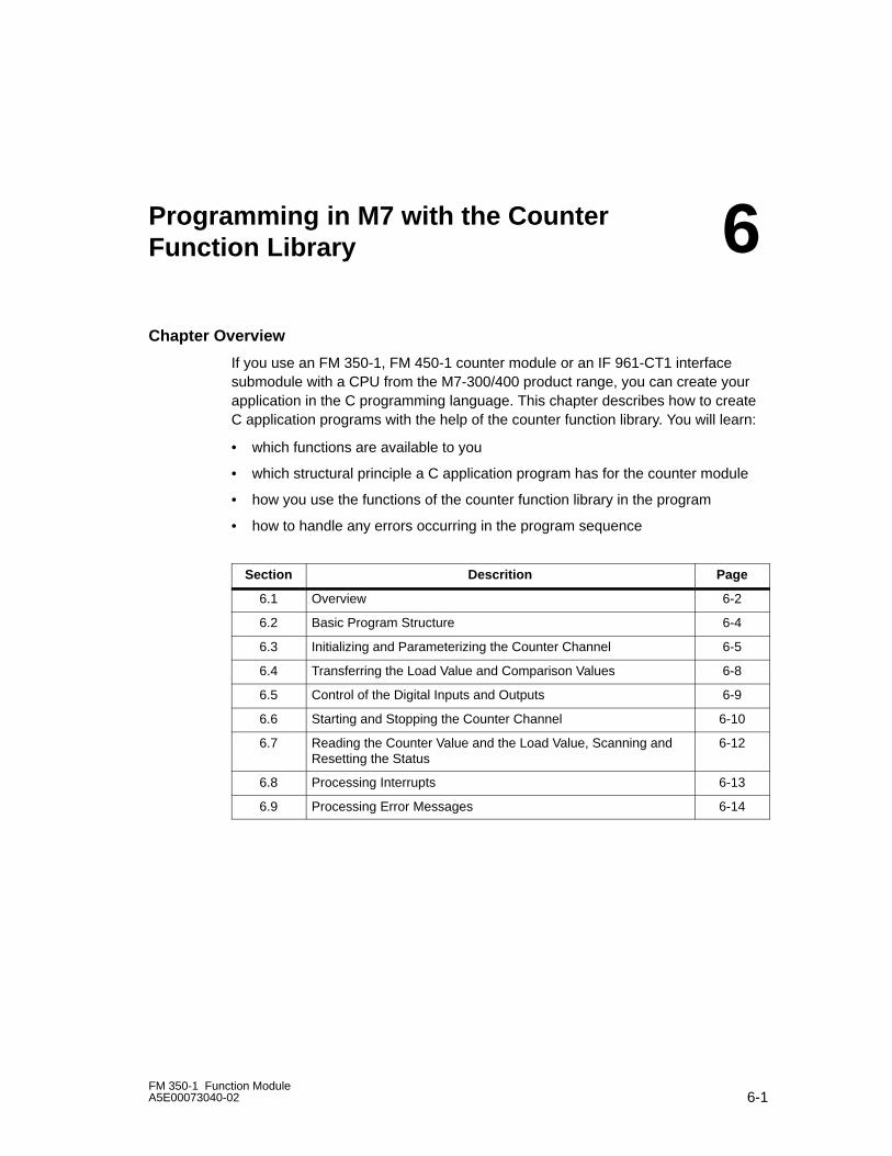
6-1FM 350-1 Function ModuleA5E00073040-02
Programming in M7 with the CounterFunction Library
Chapter Overview
If you use an FM 350-1, FM 450-1 counter module or an IF 961-CT1 interfacesubmodule with a CPU from the M7-300/400 product range, you can create yourapplication in the C programming language. This chapter describes how to createC application programs with the help of the counter function library. You will learn:
• which functions are available to you
• which structural principle a C application program has for the counter module
• how you use the functions of the counter function library in the program
• how to handle any errors occurring in the program sequence
Section Descrition Page
6.1 Overview 6-2
6.2 Basic Program Structure 6-4
6.3 Initializing and Parameterizing the Counter Channel 6-5
6.4 Transferring the Load Value and Comparison Values 6-8
6.5 Control of the Digital Inputs and Outputs 6-9
6.6 Starting and Stopping the Counter Channel 6-10
6.7 Reading the Counter Value and the Load Value, Scanning andResetting the Status
6-12
6.8 Processing Interrupts 6-13
6.9 Processing Error Messages 6-14
6
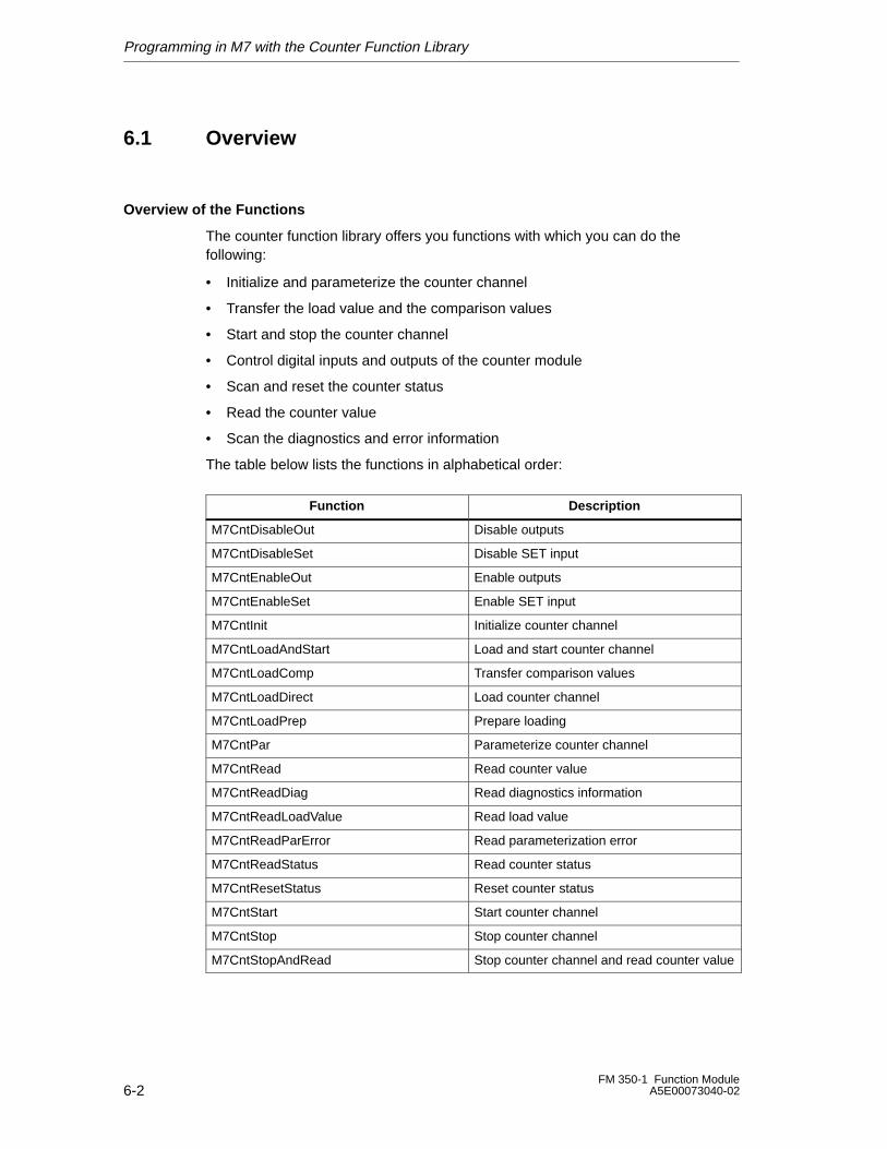
Programming in M7 with the Counter Function Library
6-2FM 350-1 Function Module
A5E00073040-02
6.1 Overview
Overview of the Functions
The counter function library offers you functions with which you can do thefollowing:
• Initialize and parameterize the counter channel
• Transfer the load value and the comparison values
• Start and stop the counter channel
• Control digital inputs and outputs of the counter module
• Scan and reset the counter status
• Read the counter value
• Scan the diagnostics and error information
The table below lists the functions in alphabetical order:
ÁÁÁÁÁÁÁÁÁÁÁÁÁÁÁÁÁÁÁÁÁÁÁÁÁÁ
Function ÁÁÁÁÁÁÁÁÁÁÁÁÁÁÁÁÁÁÁÁÁÁÁÁÁÁ
Description
ÁÁÁÁÁÁÁÁÁÁÁÁÁÁÁÁÁÁÁÁÁÁÁÁÁÁ
M7CntDisableOut ÁÁÁÁÁÁÁÁÁÁÁÁÁÁÁÁÁÁÁÁÁÁÁÁÁÁDisable outputs
ÁÁÁÁÁÁÁÁÁÁÁÁÁÁÁÁÁÁÁÁÁÁÁÁÁÁ
M7CntDisableSet ÁÁÁÁÁÁÁÁÁÁÁÁÁÁÁÁÁÁÁÁÁÁÁÁÁÁDisable SET input
ÁÁÁÁÁÁÁÁÁÁÁÁÁÁÁÁÁÁÁÁÁÁÁÁÁÁ
M7CntEnableOut ÁÁÁÁÁÁÁÁÁÁÁÁÁÁÁÁÁÁÁÁÁÁÁÁÁÁEnable outputs
ÁÁÁÁÁÁÁÁÁÁÁÁÁÁÁÁÁÁÁÁÁÁÁÁÁÁ
M7CntEnableSet ÁÁÁÁÁÁÁÁÁÁÁÁÁÁÁÁÁÁÁÁÁÁÁÁÁÁEnable SET input
ÁÁÁÁÁÁÁÁÁÁÁÁÁÁÁÁÁÁÁÁÁÁÁÁÁÁ
M7CntInit ÁÁÁÁÁÁÁÁÁÁÁÁÁÁÁÁÁÁÁÁÁÁÁÁÁÁInitialize counter channel
ÁÁÁÁÁÁÁÁÁÁÁÁÁÁÁÁÁÁÁÁÁÁÁÁÁÁ
M7CntLoadAndStartÁÁÁÁÁÁÁÁÁÁÁÁÁÁÁÁÁÁÁÁÁÁÁÁÁÁLoad and start counter channel
ÁÁÁÁÁÁÁÁÁÁÁÁÁÁÁÁÁÁÁÁÁÁÁÁÁÁ
M7CntLoadCompÁÁÁÁÁÁÁÁÁÁÁÁÁÁÁÁÁÁÁÁÁÁÁÁÁÁTransfer comparison values
ÁÁÁÁÁÁÁÁÁÁÁÁÁÁÁÁÁÁÁÁÁÁÁÁÁÁ
M7CntLoadDirectÁÁÁÁÁÁÁÁÁÁÁÁÁÁÁÁÁÁÁÁÁÁÁÁÁÁLoad counter channelÁÁÁÁÁÁÁÁÁÁÁÁÁ
ÁÁÁÁÁÁÁÁÁÁÁÁÁM7CntLoadPrepÁÁÁÁÁÁÁÁÁÁÁÁÁÁÁÁÁÁÁÁÁÁÁÁÁÁPrepare loadingÁÁÁÁÁÁÁÁÁÁÁÁÁ
ÁÁÁÁÁÁÁÁÁÁÁÁÁÁÁÁÁÁÁÁÁÁÁÁÁÁ
M7CntParÁÁÁÁÁÁÁÁÁÁÁÁÁÁÁÁÁÁÁÁÁÁÁÁÁÁÁÁÁÁÁÁÁÁÁÁÁÁÁ
Parameterize counter channel
ÁÁÁÁÁÁÁÁÁÁÁÁÁÁÁÁÁÁÁÁÁÁÁÁÁÁ
M7CntRead ÁÁÁÁÁÁÁÁÁÁÁÁÁÁÁÁÁÁÁÁÁÁÁÁÁÁ
Read counter value
ÁÁÁÁÁÁÁÁÁÁÁÁÁÁÁÁÁÁÁÁÁÁÁÁÁÁ
M7CntReadDiag ÁÁÁÁÁÁÁÁÁÁÁÁÁÁÁÁÁÁÁÁÁÁÁÁÁÁRead diagnostics information
ÁÁÁÁÁÁÁÁÁÁÁÁÁÁÁÁÁÁÁÁÁÁÁÁÁÁ
M7CntReadLoadValue ÁÁÁÁÁÁÁÁÁÁÁÁÁÁÁÁÁÁÁÁÁÁÁÁÁÁRead load value
ÁÁÁÁÁÁÁÁÁÁÁÁÁÁÁÁÁÁÁÁÁÁÁÁÁÁ
M7CntReadParError ÁÁÁÁÁÁÁÁÁÁÁÁÁÁÁÁÁÁÁÁÁÁÁÁÁÁRead parameterization error
ÁÁÁÁÁÁÁÁÁÁÁÁÁÁÁÁÁÁÁÁÁÁÁÁÁÁ
M7CntReadStatus ÁÁÁÁÁÁÁÁÁÁÁÁÁÁÁÁÁÁÁÁÁÁÁÁÁÁRead counter status
ÁÁÁÁÁÁÁÁÁÁÁÁÁÁÁÁÁÁÁÁÁÁÁÁÁÁ
M7CntResetStatus ÁÁÁÁÁÁÁÁÁÁÁÁÁÁÁÁÁÁÁÁÁÁÁÁÁÁReset counter status
ÁÁÁÁÁÁÁÁÁÁÁÁÁÁÁÁÁÁÁÁÁÁÁÁÁÁ
M7CntStart ÁÁÁÁÁÁÁÁÁÁÁÁÁÁÁÁÁÁÁÁÁÁÁÁÁÁStart counter channel
ÁÁÁÁÁÁÁÁÁÁÁÁÁÁÁÁÁÁÁÁÁÁÁÁÁÁ
M7CntStop ÁÁÁÁÁÁÁÁÁÁÁÁÁÁÁÁÁÁÁÁÁÁÁÁÁÁStop counter channel
ÁÁÁÁÁÁÁÁÁÁÁÁÁÁÁÁÁÁÁÁÁÁÁÁÁÁ
M7CntStopAndRead ÁÁÁÁÁÁÁÁÁÁÁÁÁÁÁÁÁÁÁÁÁÁÁÁÁÁStop counter channel and read counter value
Programming in M7 with the Counter Function Library
6-3FM 350-1 Function ModuleA5E00073040-02
In the following sections you will learn how to use these functions in the userprogram.
This chapter does not contain a detailed description of the individual parameters orfunction arguments. Please see Chapter 11 for these.
Programming Environment
All the system functions and standard functions of the M7-300/400 system softwareare available to you for programming in the Borland C/C++ developmentenvironment in STEP 7.
System functions support you in the following, for example:
• Task management
• Memory management
• Communications
• Interrupt processing
• Diagnostics processing
• Responding to system states
• Accessing process I/O
In addition, you can use the standard functions of the RMOS CRUN library.
You will find descriptions of these functions in the M7-300/400 system softwaremanuals.
Header File
When creating a C program for counter control, you must link in the header fileM7CNT.H in the declaration section. All other necessary header files are alreadylinked when you work with Borland C programs.
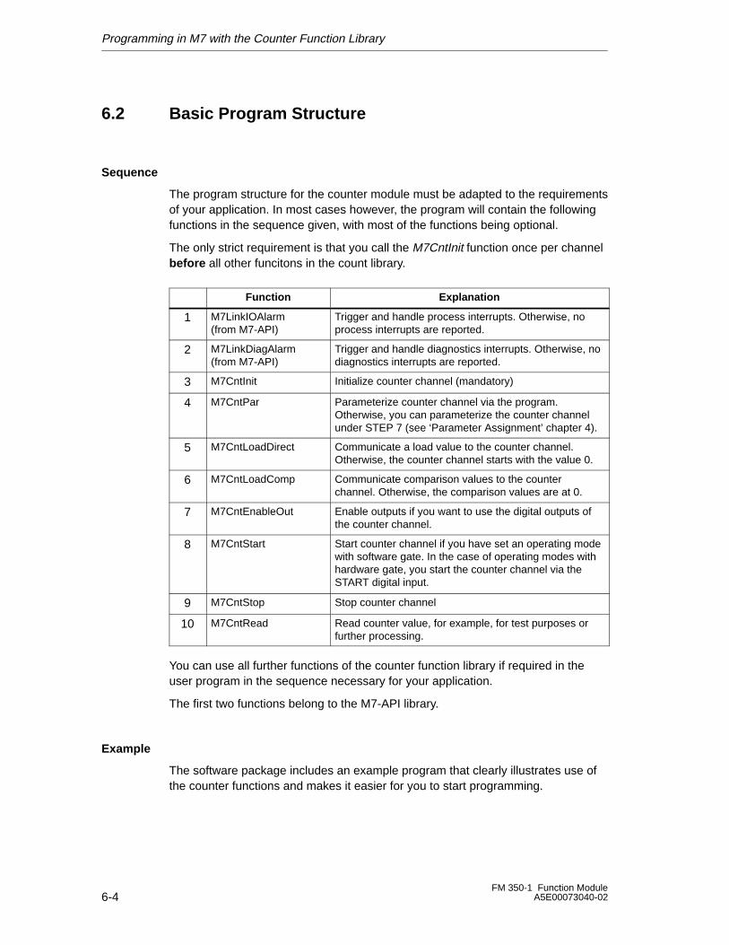
Programming in M7 with the Counter Function Library
6-4FM 350-1 Function Module
A5E00073040-02
6.2 Basic Program Structure
Sequence
The program structure for the counter module must be adapted to the requirementsof your application. In most cases however, the program will contain the followingfunctions in the sequence given, with most of the functions being optional.
The only strict requirement is that you call the M7CntInit function once per channelbefore all other funcitons in the count library.
Function Explanation
1ÁÁÁÁÁÁÁÁÁÁÁÁÁÁÁÁÁÁÁÁÁÁÁÁ
M7LinkIOAlarm (from M7-API)
ÁÁÁÁÁÁÁÁÁÁÁÁÁÁÁÁÁÁÁÁÁÁÁÁÁÁÁÁÁÁÁÁÁÁÁÁÁÁÁÁÁÁÁÁÁÁÁÁ
Trigger and handle process interrupts. Otherwise, noprocess interrupts are reported.
2 ÁÁÁÁÁÁÁÁÁÁÁÁÁÁÁÁÁÁÁÁÁÁÁÁ
M7LinkDiagAlarm(from M7-API)
ÁÁÁÁÁÁÁÁÁÁÁÁÁÁÁÁÁÁÁÁÁÁÁÁÁÁÁÁÁÁÁÁÁÁÁÁÁÁÁÁÁÁÁÁÁÁÁÁ
Trigger and handle diagnostics interrupts. Otherwise, nodiagnostics interrupts are reported.
3 ÁÁÁÁÁÁÁÁÁÁÁÁÁÁÁÁ
M7CntInit ÁÁÁÁÁÁÁÁÁÁÁÁÁÁÁÁÁÁÁÁÁÁÁÁÁÁÁÁÁÁÁÁInitialize counter channel (mandatory)
4 ÁÁÁÁÁÁÁÁÁÁÁÁÁÁÁÁÁÁÁÁÁÁÁÁ
M7CntPar ÁÁÁÁÁÁÁÁÁÁÁÁÁÁÁÁÁÁÁÁÁÁÁÁÁÁÁÁÁÁÁÁÁÁÁÁÁÁÁÁÁÁÁÁÁÁÁÁ
Parameterize counter channel via the program.Otherwise, you can parameterize the counter channelunder STEP 7 (see ‘Parameter Assignment’ chapter 4).
5ÁÁÁÁÁÁÁÁÁÁÁÁÁÁÁÁÁÁÁÁÁÁÁÁ
M7CntLoadDirectÁÁÁÁÁÁÁÁÁÁÁÁÁÁÁÁÁÁÁÁÁÁÁÁÁÁÁÁÁÁÁÁÁÁÁÁÁÁÁÁÁÁÁÁÁÁÁÁ
Communicate a load value to the counter channel.Otherwise, the counter channel starts with the value 0.
6ÁÁÁÁÁÁÁÁÁÁÁÁÁÁÁÁÁÁÁÁÁÁÁÁ
M7CntLoadCompÁÁÁÁÁÁÁÁÁÁÁÁÁÁÁÁÁÁÁÁÁÁÁÁÁÁÁÁÁÁÁÁÁÁÁÁÁÁÁÁÁÁÁÁÁÁÁÁ
Communicate comparison values to the counterchannel. Otherwise, the comparison values are at 0.
7 ÁÁÁÁÁÁÁÁÁÁÁÁÁÁÁÁÁÁÁÁÁÁÁÁ
M7CntEnableOut ÁÁÁÁÁÁÁÁÁÁÁÁÁÁÁÁÁÁÁÁÁÁÁÁÁÁÁÁÁÁÁÁÁÁÁÁÁÁÁÁÁÁÁÁÁÁÁÁ
Enable outputs if you want to use the digital outputs ofthe counter channel.
8 ÁÁÁÁÁÁÁÁÁÁÁÁÁÁÁÁÁÁÁÁÁÁÁÁÁÁÁÁÁÁÁÁ
M7CntStart ÁÁÁÁÁÁÁÁÁÁÁÁÁÁÁÁÁÁÁÁÁÁÁÁÁÁÁÁÁÁÁÁÁÁÁÁÁÁÁÁÁÁÁÁÁÁÁÁÁÁÁÁÁÁÁÁÁÁÁÁÁÁÁÁ
Start counter channel if you have set an operating modewith software gate. In the case of operating modes withhardware gate, you start the counter channel via theSTART digital input.
9 ÁÁÁÁÁÁÁÁÁÁÁÁÁÁÁÁ
M7CntStop ÁÁÁÁÁÁÁÁÁÁÁÁÁÁÁÁÁÁÁÁÁÁÁÁÁÁÁÁÁÁÁÁStop counter channel
10 ÁÁÁÁÁÁÁÁÁÁÁÁÁÁÁÁÁÁÁÁÁÁÁÁ
M7CntRead ÁÁÁÁÁÁÁÁÁÁÁÁÁÁÁÁÁÁÁÁÁÁÁÁÁÁÁÁÁÁÁÁÁÁÁÁÁÁÁÁÁÁÁÁÁÁÁÁ
Read counter value, for example, for test purposes orfurther processing.
You can use all further functions of the counter function library if required in theuser program in the sequence necessary for your application.
The first two functions belong to the M7-API library.
Example
The software package includes an example program that clearly illustrates use ofthe counter functions and makes it easier for you to start programming.
Programming in M7 with the Counter Function Library
6-5FM 350-1 Function ModuleA5E00073040-02
6.3 Initializing and Parameterizing the Counter Channel
M7CntInit Initializing the Counter Channel
Counter channels are initialized via the M7CntInit function. The M7CntInit functionmust be called once for each counter channel used. It assigns a ‘logical’ channelnumber to the address of the counter channel. You specify the address of thecounter channel as a parameter. It consists of the following:
• The module starting address
With M7-300, you can specify the slot-dependent default starting address or anaddress parameterized with STEP 7. With M7-400, you specify the startingaddress parameterized withSTEP 7.
If you have assigned a symbol to the address, you can import this symbol intoyour user program (see ‘ProC/C++ for M7-300/400’ User Manual).
• Input type (always M7IO_IN or M7IO_OUT, it doesn’t matter which)
• Channel number
The channel number can take the following values:
– in the FM 350-1 and IF counters the value is equal to 1 (1 channel)
– in the FM 350-1 the value is {1/2} (2 channels)
Logical Channel Number
The function supplies the ‘logical’ channel number that you use for all furtheraccesses to this counter channel.
Example
M7CntInit (CNTMODULEADDRESS, M7IO_IN, 1, &LogChannel)
The parameter &LogChannel contains the return value of the function, the ‘logical’channel number.
Programming in M7 with the Counter Function Library
6-6FM 350-1 Function Module
A5E00073040-02
Parameterizing the Counter Channel
Parameterizing sets the counter module to the requirements of your application.You select the following, for example:
• The operating mode (with software gate or hardware gate)
• The sensor type (24 V or 5 V)
• The interrupt characteristics of the counter channel, etc.
See Chapter 8 for explanations of the settings.
The counter module must be parameterized. If a counter channel is notparameterized, you will receive an error message. There are two basic methods ofparameterizing the counter channel:
• With STEP 7
• With the M7CntPar function
Parameterizing with STEP 7
You can parameterize the counter module in a user-friendly manner via screenforms in STEP 7 (see Chapter 4). The parameterization data set with STEP 7 aretransferred to the counter module when the M7-300/400 is started up. This meansthat you must execute a SIMATIC M7 restart each time you change theparameterization data.
Note
The parameters valid at any one time cannot be read out using STEP 7.
Parameterizing the Counter Channel with M7CntPar
You can parameterize and reparameterize a counter channel via the user programusing the M7CntPar function. You specify the new parameterization data in theM7CNT_PARAM structure when you call the M7CntPar function (see the functionlibrary). The function transfers the parameterization data to the counter module andthe new settings become effective immediately.
Programming in M7 with the Counter Function Library
6-7FM 350-1 Function ModuleA5E00073040-02
Note
When you call the M7CntPar function, all the current parameterization data arealways completely overwritten and no part parameterizations can be made.
When reparameterizations are made, any previously stored input or outputenables are lost. This means that the M7CntEnableSet and, for example,M7CntEnableOut functions may have to be called again after M7CntPar.
Reparameterization overwrites already set comparison values and the load value.
When reparameterizing with the M7CntPar function, counter pulses can also belost.
Reparameterization does not affect the other counter channel in the FM 350-1.
Parameterization Data
Table 11-1 (page 11-34) shows you the assignments between the components ofthe M7CNT_PARAM structure and the parameterization data, data type, valuerange and default value.
Programming in M7 with the Counter Function Library
6-8FM 350-1 Function Module
A5E00073040-02
6.4 Transferring the Load Value and Comparison Values
Load Value
You can specify a starting value, the load value (LoadVal) to the counter channel.The default load value is 0.
M7CntLoadDirect M7CntLoadPrep
The load value can be transferred direct to the counter channel or it can be storedtemporarily in the counter-internal load register.
The counter channel can be loaded direct with the M7CntLoadDirect function.
With the M7CntLoadPrep function, the load value is not transferred direct to thecounter channel, but stored temporarily in the counter channel. The counterchannel accepts the load value if:
• a hardware pulse exists at the SET or START input
• an overflow or underflow takes place and a periodic operating mode is set
• the M7CntStart function is called
Comparison Values
You can use the comparison values to control the digital outputs and to triggerinterrupts: As soon as the comparison value has been reached, an output can beset, thus triggering a control action. In addition, you can stipulate that a processinterrupt is to be triggered as soon as a specific comparison value has beenreached. You determine the behavior of the digital outputs via parameterization.chapter 8 contains a description of the possible settings and their effects.
If you control the digital outputs with the comparison values, you must enable thedigital outputs with the M7CntEnableOut function. This call is also required afterreparameterization of the counter channel.
M7CntLoadComp
You can transfer one or two comparison values to the counter channel with theM7CntLoadComp.
Programming in M7 with the Counter Function Library
6-9FM 350-1 Function ModuleA5E00073040-02
6.5 Control of the Digital Inputs and Outputs
Digital Inputs
The counter module has the digital inputs START, STOP, RESET (IF 961-CT1 only)and SET.
If an operating mode with hardware gate control has been set, you can control thecounter module via hardware signals.
Using the SET digital input, the counter channel can be set to the load value via anexternal signal (see Chapter 8).
M7CntEnableSet
The SET input is enabled with the M7CntEnableSet function. The SET input (or theassociated loading of the counter channel) can be enabled for the up countdirection, the down count direction or both count directions with only one functioncall.
M7CntDisableSet
Analogously, the SET input can be disabled via the M7CntDisableSet function. TheSET input can be disabled for the up count direction, the down count direction orboth count directions with only one function call in the same way as it could beenabled.
Digital Outputs
The counter module has two digital outputs (per counter channel) that you can useto trigger responses in the process independently of the CPU.
M7CntEnableOut
With the M7CntEnableOut function, one output or two of two possible outputs canbe enabled with a single function call. The function enables the physical output.
M7CntDisableOut
With the M7CntDisableOut function, each output can be disabled individually orboth outputs can be disabled simultaneously with a single function call.
Programming in M7 with the Counter Function Library
6-10FM 350-1 Function Module
A5E00073040-02
6.6 Starting and Stopping the Counter Channel
Starting the Counter Channel
Depending on the operating mode, with hardware or software gate control, thereare two methods of starting the counter channel:
1. Via the software gate with the M7CntStart function
2. Via the hardware gate by a signal at the START digital input.
You set the operating mode via parameterization.
M7CntStart
Using the M7CntStart, the counter channel is started via the software gate. Thefunction opens the software gate.
M7CntLoadAndStart
In addition, the counter channel can be started via the M7CntLoadAndStartfunction. When called, this function transfers a load value direct to the counterchannel. Like M7CntStart, this function also starts the counter channel via thesoftware gate.
Note
In the case of the operating modes with hardware gate control, the M7CntStartand M7CntLoadAndStart functions initiate a message pointing out an operatorerror.
Stopping the Counter Channel
There are two methods of stopping the counter channel:
1. Via the software gate with one of the M7CntStop or M7CntStopandReadfunctions.
2. Via the hardware gate by a signal at the STOP digital input
M7CntStop
The counter channel is stopped with the M7CntStop function. The gate stopfunction of the counter channel is switched on with this function. The functionoperates independent of the method of gate control (hardware gate or softwaregate).
Programming in M7 with the Counter Function Library
6-11FM 350-1 Function ModuleA5E00073040-02
Note
If a counter channel with hardware gate control is stopped with the M7CntStopfunction, the counter channel cannot be started until parameterization orreparameterization (M7CntPar function) has taken place.
M7CntStopAndRead
The counter channel can also be stopped via the M7CntStopAndRead function.This function stops the counter channel and reads the counter status. The functionis possible in all operating modes with gate control.
Programming in M7 with the Counter Function Library
6-12FM 350-1 Function Module
A5E00073040-02
6.7 Reading the Counter Value and the Load Value,Scanning and Resetting the Status
Scanning Information
The functions listed below are used for scanning information such as
• Counter value
• Load value
• Counter status
The counter status can be reset if required.
M7CntRead
The counter status can be read with M7CntRead. The current status of the counterchannel is read and stored in the pActCntV return parameter.
M7CntStop AndRead
The M7CntStopAndRead function stops the counter channel and reads the counterstatus simultaneously. The current counter status is then stored in pActCntV.
M7CntRead LoadValue
The load value of a counter channel can be read with M7CntReadLoadValue.
Scanning the Counter Status
You can scan the status of the counter channel with the M7CntReadStatusfunction. The function returns the counter status. See the description ofM7CntReadStatus in Chapter 11 for the meaning of the individual bits in thecounter status. The function can be used, for example, to scan the zero pass tosee if the counter channel is running, if the counter overflow has taken place, whichcounter direction is in force, etc.
Resetting the Counter Status
Bits that have been set in M7CntReadStatus can be reset again via theM7CntResetStatus, in order, for example, to detect a renewed zero pass or arenewed counter synchronization (multiple setting via SET digital input).
Programming in M7 with the Counter Function Library
6-13FM 350-1 Function ModuleA5E00073040-02
6.8 Processing Interrupts
Registering at the Interrupt Server
Depending on the parameters assigned, the counter module can initiate processinterrupts and/or diagnostics interrupts. In order to receive process interrupts anddiagnostics interrupts, the counter channel must be registered with the interruptserver. For this purpose, you must call the following functions:
• M7LinkIOAlarm, to receive process interrupts
• M7LinkDiagAlarm, to receive diagnostics interrupts
See the System Software for M7-300 and M7-400 Programming Manual for detailsof how to work with the interrupt server.
Evaluating Process Interrupts
Your parameter assignments determine if the counter module is to initiate processinterrupts and if so which process interrupts it is to initiate (see Table11-1). Ifrequired, you define the responses to process interrupts in the program.
Evaluating Diagnostics Interrupts
If a diagnostics interrupt is signaled by the interrupt server you must evaluate thesignal (data set DS0) in order to determine the cause of the interrupt. You can callthe following functions from the counter function library to get additionalinformation:
• M7CntReadDiag, if the diagnosis is ‘Error in one channel’.
• M7CntReadParError, if the diagnosis is ‘Parameter assignment error’.
M7CntReadDiag
By calling the M7CntReadDiag function, you can scan additional information on thechannel error. When the function is called, the diagnostics data set DS1 is read.Data set DS1 contains the additional channel-specific diagnostics information. Thefirst 4 bytes of DS1 contain the current DS0 data set.
The diagnostics interrupts and data sets DS0 and DS1 are explained inChapter 12.
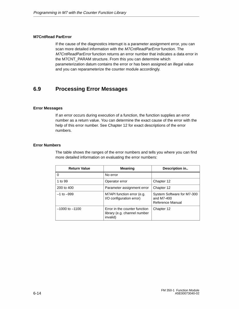
Programming in M7 with the Counter Function Library
6-14FM 350-1 Function Module
A5E00073040-02
M7CntRead ParError
If the cause of the diagnostics interrupt is a parameter assignment error, you canscan more detailed information with the M7CntReadParError function. TheM7CntReadParError function returns an error number that indicates a data error inthe M7CNT_PARAM structure. From this you can determine whichparameterization datum contains the error or has been assigned an illegal valueand you can reparameterize the counter module accordingly.
6.9 Processing Error Messages
Error Messages
If an error occurs during execution of a function, the function supplies an errornumber as a return value. You can determine the exact cause of the error with thehelp of this error number. See Chapter 12 for exact descriptions of the errornumbers.
Error Numbers
The table shows the ranges of the error numbers and tells you where you can findmore detailed information on evaluating the error numbers:
ÁÁÁÁÁÁÁÁÁÁÁÁÁÁÁÁÁÁ
Return Value ÁÁÁÁÁÁÁÁÁÁÁÁÁÁÁÁÁÁ
Meaning ÁÁÁÁÁÁÁÁÁÁÁÁÁÁÁÁÁÁ
Description in..ÁÁÁÁÁÁÁÁÁÁÁÁÁÁÁÁÁÁ
0ÁÁÁÁÁÁÁÁÁÁÁÁÁÁÁÁÁÁ
No errorÁÁÁÁÁÁÁÁÁÁÁÁÁÁÁÁÁÁÁÁÁÁÁÁÁÁÁ
ÁÁÁÁÁÁÁÁÁ1 to 99
ÁÁÁÁÁÁÁÁÁÁÁÁÁÁÁÁÁÁ
Operator errorÁÁÁÁÁÁÁÁÁÁÁÁÁÁÁÁÁÁ
Chapter 12ÁÁÁÁÁÁÁÁÁÁÁÁÁÁÁÁÁÁ200 to 400
ÁÁÁÁÁÁÁÁÁÁÁÁÁÁÁÁÁÁParameter assignment error
ÁÁÁÁÁÁÁÁÁÁÁÁÁÁÁÁÁÁChapter 12ÁÁÁÁÁÁÁÁÁ
ÁÁÁÁÁÁÁÁÁÁÁÁÁÁÁÁÁÁÁÁÁÁÁÁÁÁÁ
–1 to –999ÁÁÁÁÁÁÁÁÁÁÁÁÁÁÁÁÁÁÁÁÁÁÁÁÁÁÁÁÁÁÁÁÁÁÁÁ
M7API function error (e.g.I/O configuration error)
ÁÁÁÁÁÁÁÁÁÁÁÁÁÁÁÁÁÁÁÁÁÁÁÁÁÁÁÁÁÁÁÁÁÁÁÁ
System Software for M7-300and M7-400Reference Manual
ÁÁÁÁÁÁÁÁÁÁÁÁÁÁÁÁÁÁÁÁÁÁÁÁÁÁÁ
–1000 to –1100 ÁÁÁÁÁÁÁÁÁÁÁÁÁÁÁÁÁÁÁÁÁÁÁÁÁÁÁ
Error in the counter functionlibrary (e.g. channel numberinvalid)
ÁÁÁÁÁÁÁÁÁÁÁÁÁÁÁÁÁÁÁÁÁÁÁÁÁÁÁ
Chapter 12
7-1FM 350-1 Function ModuleA5E00073040-02
Starting Up the FM 350-1
Chapter Overview
This chapter contains the checklists for starting up the FM 350-1. These checklistsenable you to:
• check all working steps prior to operating the module
• avoid operating faults in the module
Section Description Page
7.1 Mechanical Installation Checklist 7-2
7.2 Parameter Assignment Checklist 7-4
7
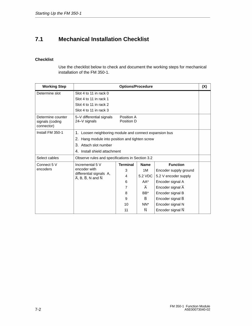
Starting Up the FM 350-1
7-2FM 350-1 Function Module
A5E00073040-02
7.1 Mechanical Installation Checklist
Checklist
Use the checklist below to check and document the working steps for mechanicalinstallation of the FM 350-1.
Working Step Options/Procedure (X)
Determine slot Slot 4 to 11 in rack 0
Slot 4 to 11 in rack 1
Slot 4 to 11 in rack 2
Slot 4 to 11 in rack 3
Determine countersignals (codingconnector)
5–V differential signals Position A24–V signals Position D
Install FM 350-1 1. Loosen neighboring module and connect expansion bus
2. Hang module into position and tighten screw
3. Attach slot number
4. Install shield attachment
Select cables Observe rules and specifications in Section 3.2
Connect 5 Vencoders
Incremental 5 Vencoder withdifferential signals A,A, B, B, N and N
Terminal
3
4
6
7
8
9
10
11
Name
1M
5.2 VDC
AA*
A
BB*
B
NN*
N
Function
Encoder supply ground
5.2 V encoder supply
Encoder signal A
Encoder signal A
Encoder signal B
Encoder signal B
Encoder signal N
Encoder signal N
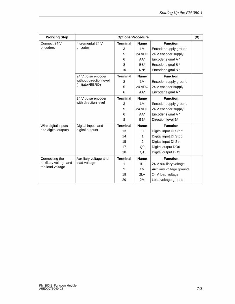
Starting Up the FM 350-1
7-3FM 350-1 Function ModuleA5E00073040-02
Working Step (X)Options/Procedure
Connect 24 Vencoders
Incremental 24 Vencoder
Terminal
3
5
6
8
10
Name
1M
24 VDC
AA*
BB*
NN*
Function
Encoder supply ground
24 V encoder supply
Encoder signal A *
Encoder signal B *
Encoder signal N *
24 V pulse encoderwithout direction level(initiator/BERO)
Terminal
3
5
6
Name
1M
24 VDC
AA*
Function
Encoder supply ground
24 V encoder supply
Encoder signal A *
24 V pulse encoderwith direction level
Terminal
3
5
6
8
Name
1M
24 VDC
AA*
BB*
Function
Encoder supply ground
24 V encoder supply
Encoder signal A *
Direction level B*
Wire digital inputsand digital outputs
Digital inputs anddigital outputs
Terminal
13
14
15
17
18
Name
I0
I1
I2
Q0
Q1
Function
Digital input DI Start
Digital input DI Stop
Digital input DI Set
Digital output DO0
Digital output DO1
Connecting theauxiliary voltage andthe load voltage
Auxiliary voltage andload voltage
Terminal
1
2
19
20
Name
1L+
1M
2L+
2M
Function
24 V auxiliary voltage
Auxiliary voltage ground
24 V load voltage
Load voltage ground
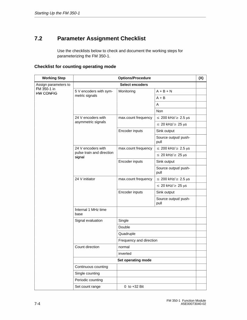
Starting Up the FM 350-1
7-4FM 350-1 Function Module
A5E00073040-02
7.2 Parameter Assignment Checklist
Use the checklists below to check and document the working steps forparameterizing the FM 350-1.
Checklist for counting operating mode
Working Step Options/Procedure (X)
Assign parameters toFM 350 1 in
Select encoders FM 350-1 inHW CONFIG
5 V encoders with sym-metric signals
Monitoring A + B + NHW CONFIGmetric signals
A + B
A
Non
24 V encoders witht i i l
max.count frequency � 200 kHz/� 2.5 �sasymmetric signals
� 20 kHz/� 25 �s
Encoder inputs Sink output
Source output/ push-pull
24 V encoders withp lse train and direction
max.count frequency � 200 kHz/� 2.5 �spulse train and directionsignal � 20 kHz/� 25 �ssignal
Encoder inputs Sink output
Source output/ push-pull
24 V initiator max.count frequency � 200 kHz/� 2.5 �s
� 20 kHz/� 25 �s
Encoder inputs Sink output
Source output/ push-pull
Internal 1 MHz timebase
Signal evaluation Single
Double
Quadruple
Frequency and direction
Count direction normal
inverted
Set operating mode
Continuous counting
Single counting
Periodic counting
Set count range 0 to +32 Bit
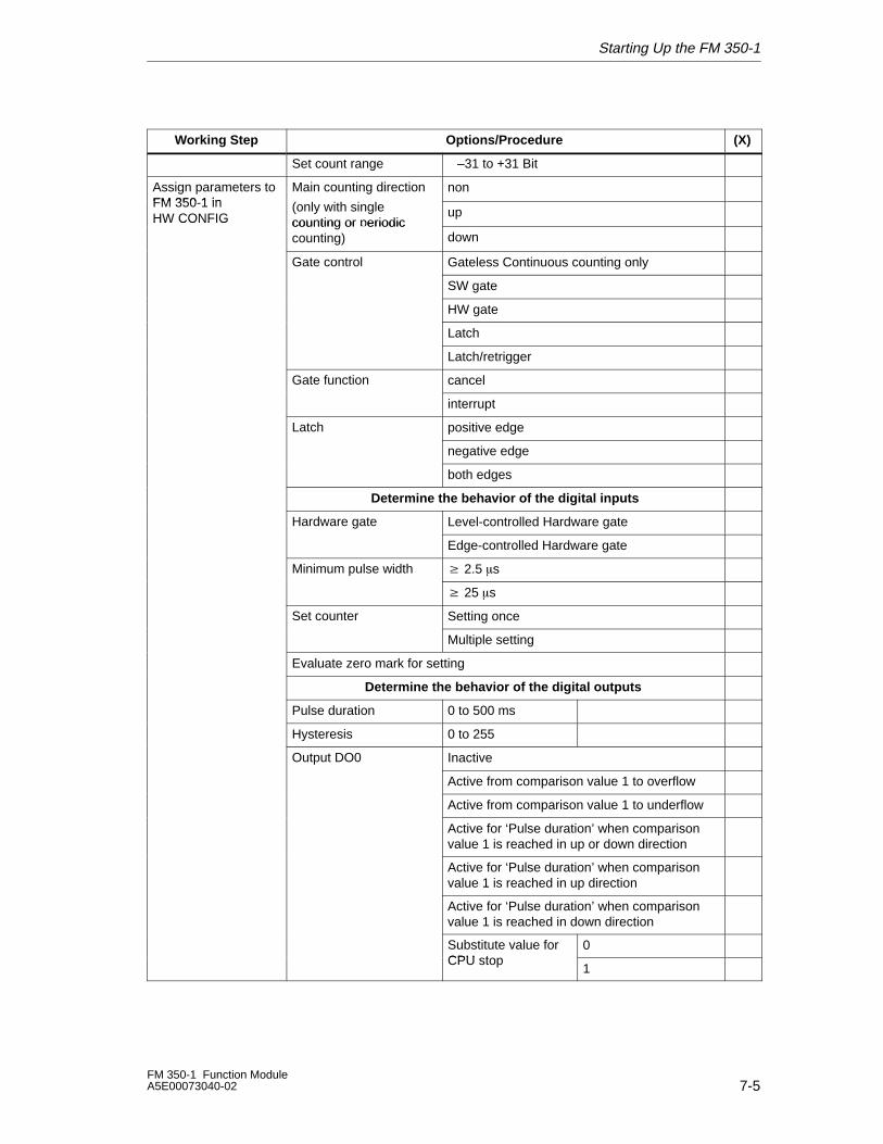
Starting Up the FM 350-1
7-5FM 350-1 Function ModuleA5E00073040-02
(X)Options/ProcedureWorking Step
Set count range –31 to +31 Bit
Assign parameters toFM 350 1 in
Main counting direction nonFM 350-1 inHW CONFIG
(only with single counting or periodic
upHW CONFIG counting or eriodiccounting) down
Gate control Gateless Continuous counting only
SW gate
HW gate
Latch
Latch/retrigger
Gate function cancel
interrupt
Latch positive edge
negative edge
both edges
Determine the behavior of the digital inputs
Hardware gate Level-controlled Hardware gate
Edge-controlled Hardware gate
Minimum pulse width � 2.5 �s
� 25 �s
Set counter Setting once
Multiple setting
Evaluate zero mark for setting
Determine the behavior of the digital outputs
Pulse duration 0 to 500 ms
Hysteresis 0 to 255
Output DO0 Inactive
Active from comparison value 1 to overflow
Active from comparison value 1 to underflow
Active for ‘Pulse duration’ when comparisonvalue 1 is reached in up or down direction
Active for ‘Pulse duration’ when comparisonvalue 1 is reached in up direction
Active for ‘Pulse duration’ when comparisonvalue 1 is reached in down direction
Substitute value forCPU stop
0CPU stop
1
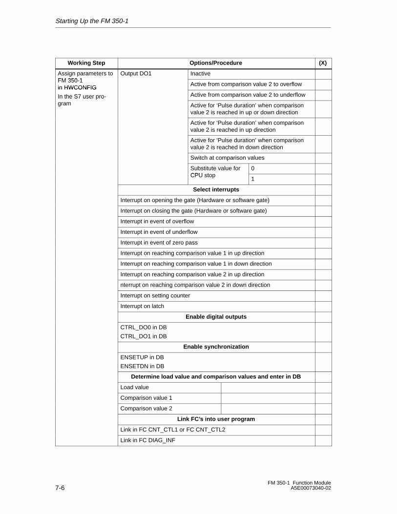
Starting Up the FM 350-1
7-6FM 350-1 Function Module
A5E00073040-02
(X)Options/ProcedureWorking Step
Assign parameters toFM 350 1
Output DO1 InactiveFM 350-1in HWCONFIG Active from comparison value 2 to overflow in HWCONFIG
In the S7 user pro- Active from comparison value 2 to underflow In the S7 user rogram Active for ‘Pulse duration’ when comparison
value 2 is reached in up or down direction
Active for ‘Pulse duration’ when comparisonvalue 2 is reached in up direction
Active for ‘Pulse duration’ when comparisonvalue 2 is reached in down direction
Switch at comparison values
Substitute value forCPU t
0CPU stop
1
Select interrupts
Interrupt on opening the gate (Hardware or software gate)
Interrupt on closing the gate (Hardware or software gate)
Interrupt in event of overflow
Interrupt in event of underflow
Interrupt in event of zero pass
Interrupt on reaching comparison value 1 in up direction
Interrupt on reaching comparison value 1 in down direction
Interrupt on reaching comparison value 2 in up direction
nterrupt on reaching comparison value 2 in down direction
Interrupt on setting counter
Interrupt on latch
Enable digital outputs
CTRL_DO0 in DB
CTRL_DO1 in DB
Enable synchronization
ENSETUP in DB
ENSETDN in DB
Determine load value and comparison values and enter in DB
Load value
Comparison value 1
Comparison value 2
Link FC’s into user program
Link in FC CNT_CTL1 or FC CNT_CTL2
Link in FC DIAG_INF
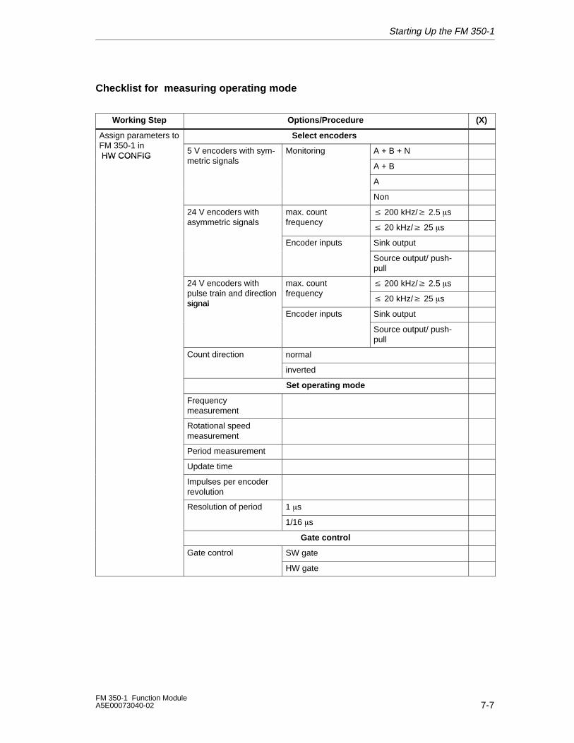
Starting Up the FM 350-1
7-7FM 350-1 Function ModuleA5E00073040-02
Checklist for measuring operating mode
Working Step Options/Procedure (X)
Assign parameters toFM 350 1 i
Select encoders FM 350-1 in HW CONFIG
5 V encoders with sym-t i i l
Monitoring A + B + N HW CONFIGmetric signals
A + B
A
Non
24 V encoders witht i i l
max. countf
� 200 kHz/� 2.5 �sasymmetric signals frequency
� 20 kHz/� 25 �s
Encoder inputs Sink output
Source output/ push-pull
24 V encoders withp lse train and direction
max. countfreq enc
� 200 kHz/� 2.5 �spulse train and directionsignal
frequency� 20 kHz/� 25 �ssignal
Encoder inputs Sink output
Source output/ push-pull
Count direction normal
inverted
Set operating mode
Frequency measurement
Rotational speed measurement
Period measurement
Update time
Impulses per encoderrevolution
Resolution of period 1 �s
1/16 �s
Gate control
Gate control SW gate
HW gate
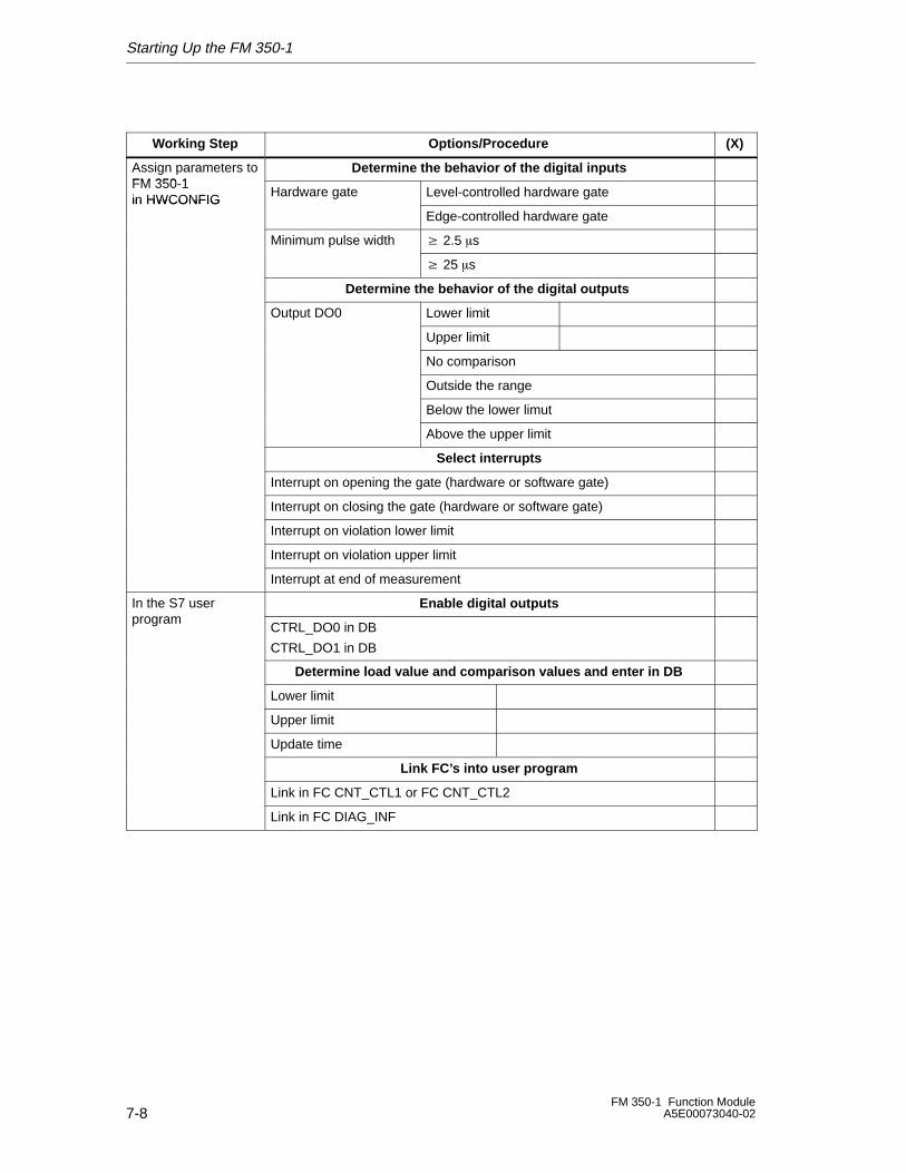
Starting Up the FM 350-1
7-8FM 350-1 Function Module
A5E00073040-02
(X)Options/ProcedureWorking Step
Assign parameters toFM 350 1
Determine the behavior of the digital inputsFM 350-1in HWCONFIG
Hardware gate Level-controlled hardware gatein HWCONFIGEdge-controlled hardware gate
Minimum pulse width � 2.5 �s
� 25 �s
Determine the behavior of the digital outputs
Output DO0 Lower limit
Upper limit
No comparison
Outside the range
Below the lower limut
Above the upper limit
Select interrupts
Interrupt on opening the gate (hardware or software gate)
Interrupt on closing the gate (hardware or software gate)
Interrupt on violation lower limit
Interrupt on violation upper limit
Interrupt at end of measurement
In the S7 user program
Enable digital outputsprogram
CTRL_DO0 in DB
CTRL_DO1 in DB
Determine load value and comparison values and enter in DB
Lower limit
Upper limit
Update time
Link FC’s into user program
Link in FC CNT_CTL1 or FC CNT_CTL2
Link in FC DIAG_INF
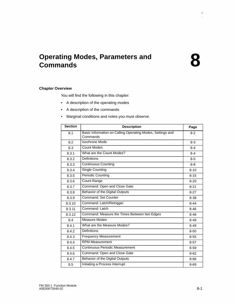
Operating Modes, Parameters and Commands
8-1FM 350-1 Function ModuleA5E00073040-02
Operating Modes, Parameters andCommands
Chapter Overview
You will find the following in this chapter:
• A description of the operating modes
• A description of the commands
• Marginal conditions and notes you must observe.
Section Description Page
8.1 Basic Information on Calling Operating Modes, Settings andCommands
8-2
8.2 Isochrone Mode 8-3
8.3 Count Modes 8-4
8.3.1 What are the Count Modes? 8-4
8.3.2 Definitions 8-5
8.3.3 Continuous Counting 8-8
8.3.4 Single Counting 8-10
8.3.5 Periodic Counting 8-15
8.3.6 Count Range 8-20
8.3.7 Command: Open and Close Gate 8-21
8.3.8 Behavior of the Digital Outputs 8-27
8.3.9 Command: Set Counter 8-38
8.3.10 Command: Latch/Retrigger 8-44
8.3.11 Command: Latch 8-46
8.3.12 Command: Measure the Times Between two Edges 8-48
8.4 Measure Modes 8-49
8.4.1 What are the Measure Modes? 8-49
8.4.2 Definitions 8-50
8.4.3 Frequency Measurement 8-55
8.4.4 RPM Measurement 8-57
8.4.5 Continuous Periodic Measurement 8-59
8.4.6 Command: Open and Close Gate 8-62
8.4.7 Behavior of the Digital Outputs 8-66
8.5 Initiating a Process Interrupt 8-69
8
Operating Modes, Parameters and Commands
8-2FM 350-1 Function Module
A5E00073040-02
8.1 Basic Information on Calling Operating Modes,Settings and Commands
How Do You Select the Operating Modes?
You select the operating modes in the parameter assignment screen forms of theFM 350-1.
The parameter assignment data are saved on the programming device andtransferred automatically to the rack SDB.
You will find information on how to install the parameter assignment screens andassign parameters to the FM 350-1 in the section entitled “Assigning Parameters tothe FM 350-1” and, after the software has been installed, in the online Help as well.
How Do You Change Operating Modes and Settings?
You can change an operating mode or setting in the parameter assignment screenforms. The new operating mode or setting becomes valid after the next FM 350-1start-up.
How Do You Give Commands?
The commands are given either via hardware signals connected to the frontconnector, or you set the relevant input parameter of the FC CNT_CTL1 in the userprogram in order to influence the count. The input parameters are stored as controlbits in the DB of the FC CNT_CTL1.
Control Bits and Status Bits in the DB
In addition to the control bits, there are status bits in the DB that signal the status ofthe counting and measuring processes. The DB has two bytes for the control bitsand two bytes for the status bits (see Chapter 10).
Transferring the Control Bits and the Status Bits
You transfer the status bits and the control bits between the CPU and the modulewith the FC CNT_CTRL that you must link into your user program:
The control bits and status bits should, if possible, be addressed symbolically in theuser program. The symbolic names are used in the description of the FC in thischapter.
You will find the precise description of the FC CNT_CTL1 in ChapterLEERER MERKER, ‘Programming the FM 350-1’ and you will find the DBassignments in Chapter 10.
Operating Modes, Parameters and Commands
8-3FM 350-1 Function ModuleA5E00073040-02
8.2 Isochrone Mode
Note
The principles of isochrone mode are described in a separate manual.
Hardware Requirements
To use the FM 350-1 in isochrone mode, you will need:
• a CPU that supports isochrone mode
• a DP master that support the equidistant bus cycle
Properties
Depending on the configuration, the FM 350-1 works in either non-isochrone orisochrone mode. The default is non-isochrone mode. If configured appropriately,the FM 350-1 automatically switches to isochrone mode without signaling thechange.
In isochrone mode, the exchange of data between the DP master and FM 350-1 isisochronous with the PROFIBUS DP cycle, i.e.:
• All control signals transferred to the FM 350-1 take effect at the time To withinthe same PROFIBUS DP cycle.
• All values and FM 350-1 status bits recorded at the time Ti are made availableat the feedback interface in the same PROFIBUS DP cycle.In isochrone mode, all 16 bytes of the feedback interface are consistent, i.e. thevalues and status bits always match one another.
• The counter value, which is affected by digital input signals, such as
– Load counter by opening the hardware gate,
– Load counter by synchronization,
– Latch and latch/retrigger a counter value
can then only take effect in the same PROFIBUS DP cycle if the event occurredbefore time Ti within this PROFIBUS DP cycle.
A parameter assignment error will prevent the FM 350-1 switching to isochronemode.
If isochrone mode is lost due to a fault or due to failure / delay of Global Control(GC), the FM 350-1 returns to isochrone mode in the next cycle without respondingto the fault.
The feedback interface is not updated if isochrone mode is lost.
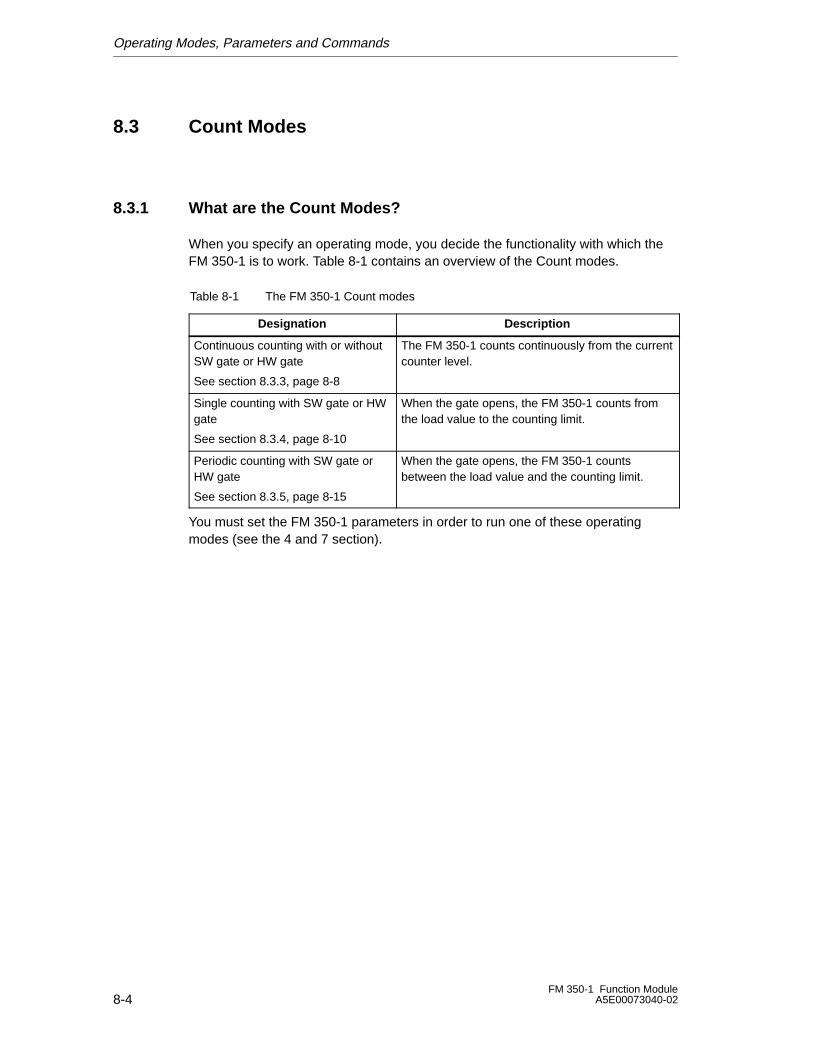
Operating Modes, Parameters and Commands
8-4FM 350-1 Function Module
A5E00073040-02
8.3 Count Modes
8.3.1 What are the Count Modes?
When you specify an operating mode, you decide the functionality with which theFM 350-1 is to work. Table 8-1 contains an overview of the Count modes.
Table 8-1 The FM 350-1 Count modes
Designation Description
Continuous counting with or withoutSW gate or HW gate
See section 8.3.3, page 8-8
The FM 350-1 counts continuously from the currentcounter level.
Single counting with SW gate or HWgate
See section 8.3.4, page 8-10
When the gate opens, the FM 350-1 counts fromthe load value to the counting limit.
Periodic counting with SW gate orHW gate
See section 8.3.5, page 8-15
When the gate opens, the FM 350-1 countsbetween the load value and the counting limit.
You must set the FM 350-1 parameters in order to run one of these operatingmodes (see the 4 and 7 section).
Operating Modes, Parameters and Commands
8-5FM 350-1 Function ModuleA5E00073040-02
8.3.2 Definitions
Load Value
You can assign a load value LOAD_VAL to the FM 350-1 during operation. This willoverwrite the starting count.
You can assign this load value directly (control signal L_DIRECT). It is thenaccepted directly by the FM 350-1 as a new counter value and loaded inpreparation.
You can load the load value in preparation only (control signal L_PREPAR). A loadvalue that is loaded in preparation is accepted by the FM 350-1 as a new countervalue in response to the following events:
In the single counting and periodic counting Count modes
– When the upper or lower limit is reached if no main counting direction is set.
– When the set upper counting limit is reached for main counting direction up.
– When 0 is reached for main counting direction down.
In all Count modes
– The counting process is started by the interrupting SW or HW gate (the loadvalue is not accepted when the counting continues).
– Synchronization
– Latch/retrigger
Gate Control
You can use the hardware gate (HW gate) and software gate (SW gate) to controlthe FM 350-1 counting processes.
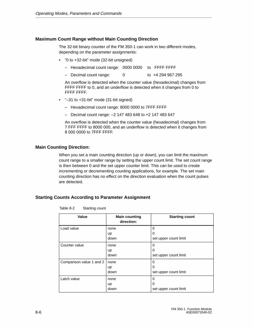
Operating Modes, Parameters and Commands
8-6FM 350-1 Function Module
A5E00073040-02
Maximum Count Range without Main Counting Direction
The 32-bit binary counter of the FM 350-1 can work in two different modes,depending on the parameter assignments:
• “0 to +32-bit” mode (32-bit unsigned)
– Hexadecimal count range: 0000 0000 to FFFF FFFF
– Decimal count range: 0 to +4 294 967 295
An overflow is detected when the counter value (hexadecimal) changes fromFFFF FFFF to 0, and an underflow is detected when it changes from 0 toFFFF FFFF.
• “–31 to +31-bit” mode (31-bit signed)
– Hexadecimal count range: 8000 0000 to 7FFF FFFF
– Decimal count range: –2 147 483 648 to +2 147 483 647
An overflow is detected when the counter value (hexadecimal) changes from7 FFF FFFF to 8000 000, and an underflow is detected when it changes from8 000 0000 to 7FFF FFFF.
Main Counting Direction:
When you set a main counting direction (up or down), you can limit the maximumcount range to a smaller range by setting the upper count limit. The set count rangeis then between 0 and the set upper counter limit. This can be used to createincrementing or decrementing counting applications, for example. The set maincounting direction has no effect on the direction evaluation when the count pulsesare detected.
Starting Counts According to Parameter Assignment
Table 8-2 Starting count
Value Main countingdirection:
Starting count
Load value noneupdown
00set upper count limit
Counter value noneupdown
00set upper count limit
Comparison value 1 and 2 noneupdown
00set upper count limit
Latch value noneupdown
00set upper count limit
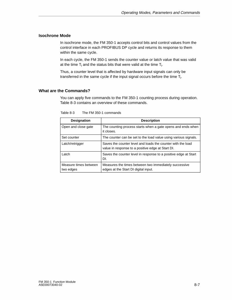
Operating Modes, Parameters and Commands
8-7FM 350-1 Function ModuleA5E00073040-02
Isochrone Mode
In isochrone mode, the FM 350-1 accepts control bits and control values from thecontrol interface in each PROFIBUS DP cycle and returns its response to themwithin the same cycle.
In each cycle, the FM 350-1 sends the counter value or latch value that was validat the time Ti and the status bits that were valid at the time Ti.
Thus, a counter level that is affected by hardware input signals can only betransferred in the same cycle if the input signal occurs before the time Ti.
What are the Commands?
You can apply five commands to the FM 350-1 counting process during operation.Table 8-3 contains an overview of these commands.
Table 8-3 The FM 350-1 commands
Designation Description
Open and close gate The counting process starts when a gate opens and ends whenit closes.
Set counter The counter can be set to the load value using various signals.
Latch/retrigger Saves the counter level and loads the counter with the loadvalue in response to a positive edge at Start DI.
Latch Saves the counter level in response to a positive edge at StartDI.
Measure times betweentwo edges
Measures the times between two immediately successiveedges at the Start DI digital input.
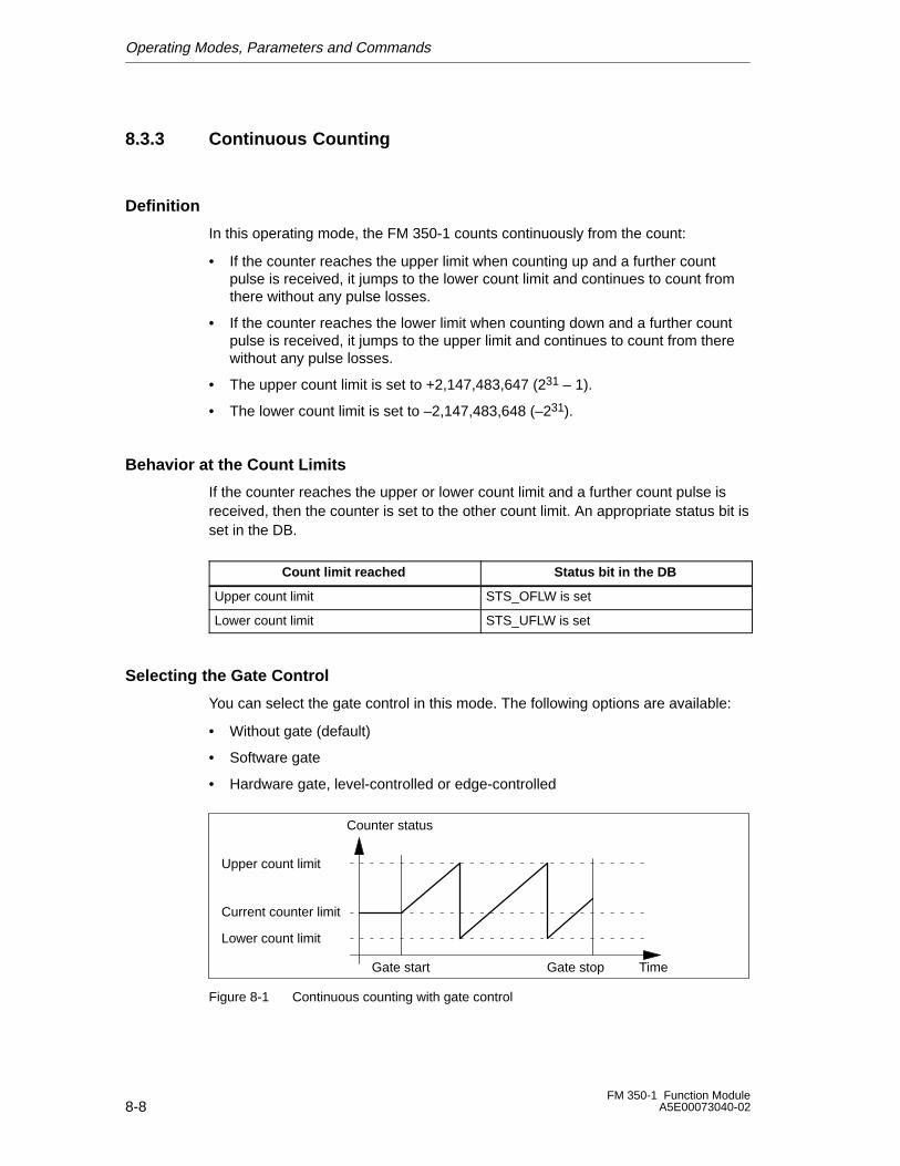
Operating Modes, Parameters and Commands
8-8FM 350-1 Function Module
A5E00073040-02
8.3.3 Continuous Counting
Definition
In this operating mode, the FM 350-1 counts continuously from the count:
• If the counter reaches the upper limit when counting up and a further countpulse is received, it jumps to the lower count limit and continues to count fromthere without any pulse losses.
• If the counter reaches the lower limit when counting down and a further countpulse is received, it jumps to the upper limit and continues to count from therewithout any pulse losses.
• The upper count limit is set to +2,147,483,647 (231 – 1).
• The lower count limit is set to –2,147,483,648 (–231).
Behavior at the Count Limits
If the counter reaches the upper or lower count limit and a further count pulse isreceived, then the counter is set to the other count limit. An appropriate status bit isset in the DB.
Count limit reached Status bit in the DB
Upper count limit STS_OFLW is set
Lower count limit STS_UFLW is set
Selecting the Gate Control
You can select the gate control in this mode. The following options are available:
• Without gate (default)
• Software gate
• Hardware gate, level-controlled or edge-controlled
Upper count limit
Lower count limit
Counter status
TimeGate start Gate stop
Current counter limit
Figure 8-1 Continuous counting with gate control
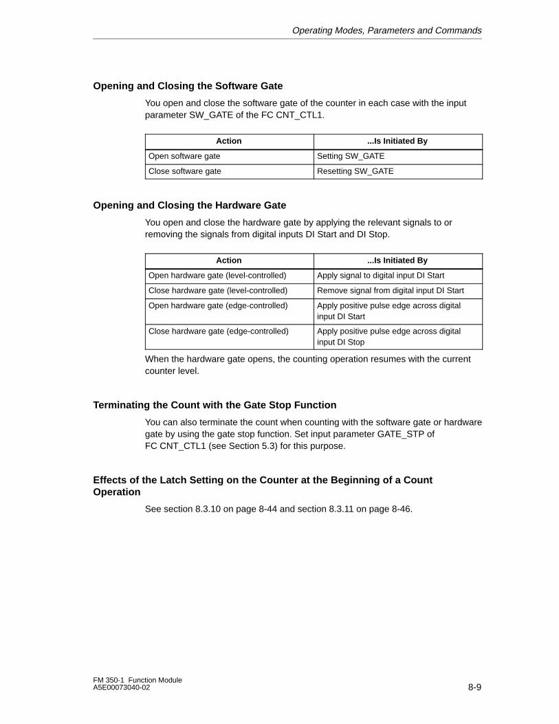
Operating Modes, Parameters and Commands
8-9FM 350-1 Function ModuleA5E00073040-02
Opening and Closing the Software Gate
You open and close the software gate of the counter in each case with the inputparameter SW_GATE of the FC CNT_CTL1.
Action ...Is Initiated By
Open software gate Setting SW_GATE
Close software gate Resetting SW_GATE
Opening and Closing the Hardware Gate
You open and close the hardware gate by applying the relevant signals to orremoving the signals from digital inputs DI Start and DI Stop.
Action ...Is Initiated By
Open hardware gate (level-controlled) Apply signal to digital input DI Start
Close hardware gate (level-controlled) Remove signal from digital input DI Start
Open hardware gate (edge-controlled) Apply positive pulse edge across digitalinput DI Start
Close hardware gate (edge-controlled) Apply positive pulse edge across digitalinput DI Stop
When the hardware gate opens, the counting operation resumes with the currentcounter level.
Terminating the Count with the Gate Stop Function
You can also terminate the count when counting with the software gate or hardwaregate by using the gate stop function. Set input parameter GATE_STP ofFC CNT_CTL1 (see Section 5.3) for this purpose.
Effects of the Latch Setting on the Counter at the Beginning of a CountOperation
See section 8.3.10 on page 8-44 and section 8.3.11 on page 8-46.
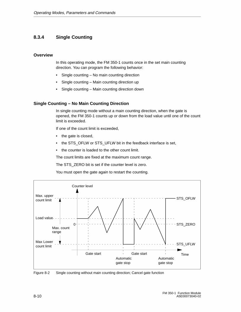
Operating Modes, Parameters and Commands
8-10FM 350-1 Function Module
A5E00073040-02
8.3.4 Single Counting
Overview
In this operating mode, the FM 350-1 counts once in the set main countingdirection. You can program the following behavior:
• Single counting – No main counting direction
• Single counting – Main counting direction up
• Single counting – Main counting direction down
Single Counting – No Main Counting Direction
In single counting mode without a main counting direction, when the gate isopened, the FM 350-1 counts up or down from the load value until one of the countlimit is exceeded.
If one of the count limit is exceeded,
• the gate is closed,
• the STS_OFLW or STS_UFLW bit in the feedback interface is set,
• the counter is loaded to the other count limit.
The count limits are fixed at the maximum count range.
The STS_ZERO bit is set if the counter level is zero.
You must open the gate again to restart the counting.
Max. uppercount limit
Max Lowercount limit
Counter level
Time
STS_OFLW
Gate start
Load value
STS_UFLW
STS_ZERO
Gate startAutomaticgate stop
0
Automaticgate stop
Max. countrange
Figure 8-2 Single counting without main counting direction; Cancel gate function
Operating Modes, Parameters and Commands
8-11FM 350-1 Function ModuleA5E00073040-02
Single Counting - Main Counting Direction Up
In single counting mode with main counting direction up, when the gate is opened,the FM 350-1 counts up or down from the load value until the upper count limit isexceeded.
If the upper count limit is exceeded,
• the gate is closed,
• the STS_OFLW bit in the feedback interface is set,
• the counter is loaded with the load value.
The upper count limit can be set. The load value has a starting count and can bechanged.
You must open the gate again to restart the counting.
Set uppercount limit
Lower countlimit = 0
STS_OFLW
Set count range
Counter level
TimeGate start
Load value
Gate start
Automaticgate stop
Automaticgate stop
Figure 8-3 Single counting without main counting direction; Cancel gate function
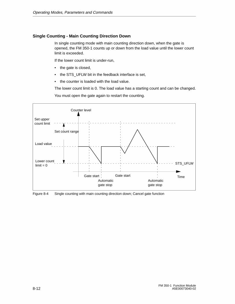
Operating Modes, Parameters and Commands
8-12FM 350-1 Function Module
A5E00073040-02
Single Counting - Main Counting Direction Down
In single counting mode with main counting direction down, when the gate isopened, the FM 350-1 counts up or down from the load value until the lower countlimit is exceeded.
If the lower count limit is under-run,
• the gate is closed,
• the STS_UFLW bit in the feedback interface is set,
• the counter is loaded with the load value.
The lower count limit is 0. The load value has a starting count and can be changed.
You must open the gate again to restart the counting.
STS_UFLW
Set uppercount limit
Lower countlimit = 0
Set count range
Counter level
TimeGate start
Load value
Gate start
Automaticgate stop
Automaticgate stop
Figure 8-4 Single counting with main counting direction down; Cancel gate function
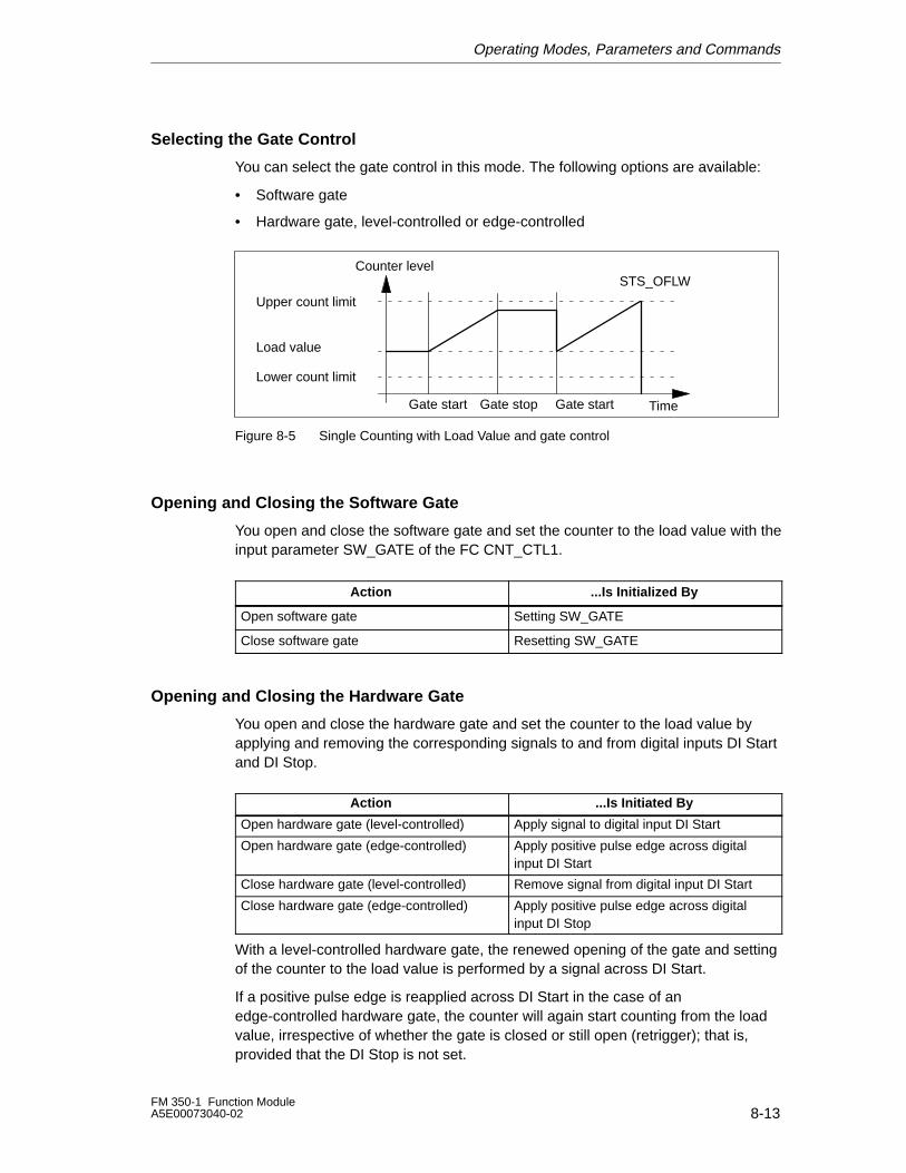
Operating Modes, Parameters and Commands
8-13FM 350-1 Function ModuleA5E00073040-02
Selecting the Gate Control
You can select the gate control in this mode. The following options are available:
• Software gate
• Hardware gate, level-controlled or edge-controlled
Upper count limit
Lower count limit
Counter level
Time
Load value
Gate start Gate stop Gate start
STS_OFLW
Figure 8-5 Single Counting with Load Value and gate control
Opening and Closing the Software Gate
You open and close the software gate and set the counter to the load value with theinput parameter SW_GATE of the FC CNT_CTL1.
Action ...Is Initialized By
Open software gate Setting SW_GATE
Close software gate Resetting SW_GATE
Opening and Closing the Hardware Gate
You open and close the hardware gate and set the counter to the load value byapplying and removing the corresponding signals to and from digital inputs DI Startand DI Stop.
Action ...Is Initiated By
Open hardware gate (level-controlled) Apply signal to digital input DI Start
Open hardware gate (edge-controlled) Apply positive pulse edge across digitalinput DI Start
Close hardware gate (level-controlled) Remove signal from digital input DI Start
Close hardware gate (edge-controlled) Apply positive pulse edge across digitalinput DI Stop
With a level-controlled hardware gate, the renewed opening of the gate and settingof the counter to the load value is performed by a signal across DI Start.
If a positive pulse edge is reapplied across DI Start in the case of anedge-controlled hardware gate, the counter will again start counting from the loadvalue, irrespective of whether the gate is closed or still open (retrigger); that is,provided that the DI Stop is not set.
Operating Modes, Parameters and Commands
8-14FM 350-1 Function Module
A5E00073040-02
Behavior at the Count Limits
If the counter has reached the upper or lower count limit and a further count pulseis received, the counter is set
– to the other count limit when counting without a main counting direction
– to the load value when counting with a main counting direction
The gate is then closed and the count is terminated even if the SW_GATEparameter is still set or the hardware gate is still open. An appropriate status bit isset in the DB.
Count Limit Reached Status bit in the DB
Upper count limit STS_OFLW is set
Lower count limit STS_UFLW is set
If you wish to restart the counter, you must reset the SW_GATE parameter orreopen the HW gate. The counting process is then continued from the load value.
Terminating the Count with the Gate Stop Function
You can also terminate the count at any time with the gate stop function. For thispurpose, set the input parameter GATE_STP of the FC CNT_CTL1.
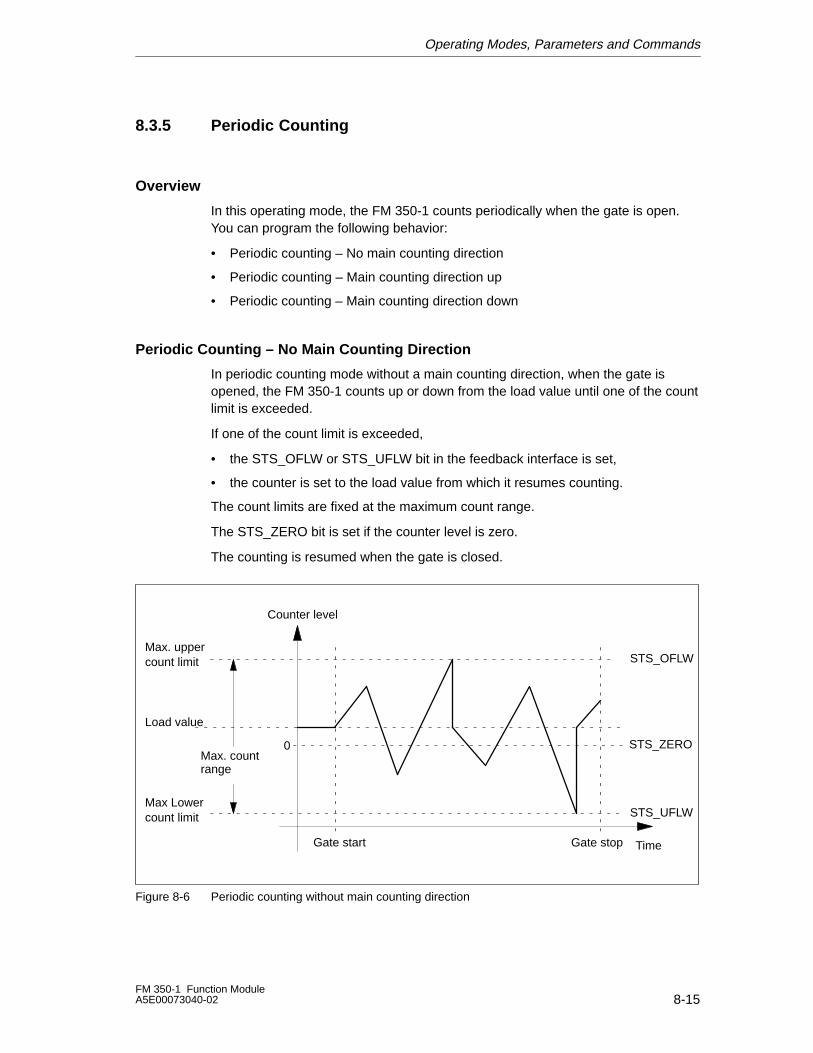
Operating Modes, Parameters and Commands
8-15FM 350-1 Function ModuleA5E00073040-02
8.3.5 Periodic Counting
Overview
In this operating mode, the FM 350-1 counts periodically when the gate is open.You can program the following behavior:
• Periodic counting – No main counting direction
• Periodic counting – Main counting direction up
• Periodic counting – Main counting direction down
Periodic Counting – No Main Counting Direction
In periodic counting mode without a main counting direction, when the gate isopened, the FM 350-1 counts up or down from the load value until one of the countlimit is exceeded.
If one of the count limit is exceeded,
• the STS_OFLW or STS_UFLW bit in the feedback interface is set,
• the counter is set to the load value from which it resumes counting.
The count limits are fixed at the maximum count range.
The STS_ZERO bit is set if the counter level is zero.
The counting is resumed when the gate is closed.
STS_OFLW
STS_UFLW
STS_ZERO0
Max. uppercount limit
Max Lowercount limit
Counter level
TimeGate start
Load value
Max. countrange
Gate stop
Figure 8-6 Periodic counting without main counting direction
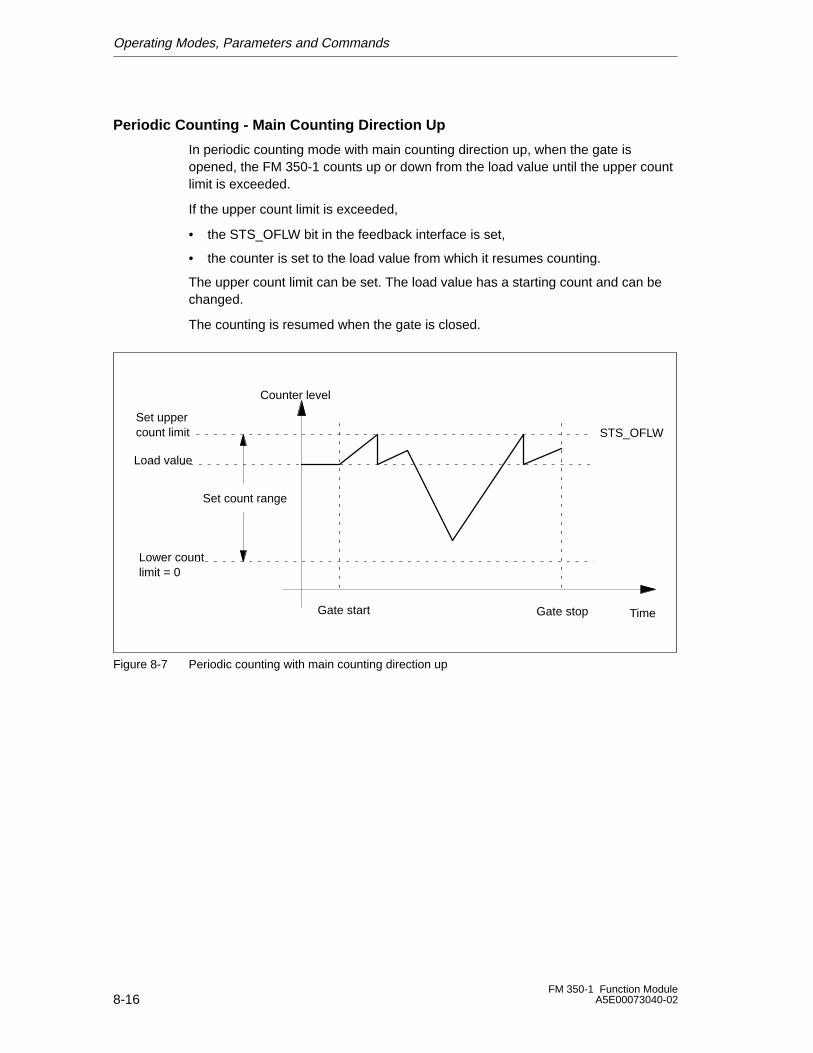
Operating Modes, Parameters and Commands
8-16FM 350-1 Function Module
A5E00073040-02
Periodic Counting - Main Counting Direction Up
In periodic counting mode with main counting direction up, when the gate isopened, the FM 350-1 counts up or down from the load value until the upper countlimit is exceeded.
If the upper count limit is exceeded,
• the STS_OFLW bit in the feedback interface is set,
• the counter is set to the load value from which it resumes counting.
The upper count limit can be set. The load value has a starting count and can bechanged.
The counting is resumed when the gate is closed.
STS_OFLWSet uppercount limit
Lower countlimit = 0
Set count range
Counter level
TimeGate start
Load value
Gate stop
Figure 8-7 Periodic counting with main counting direction up
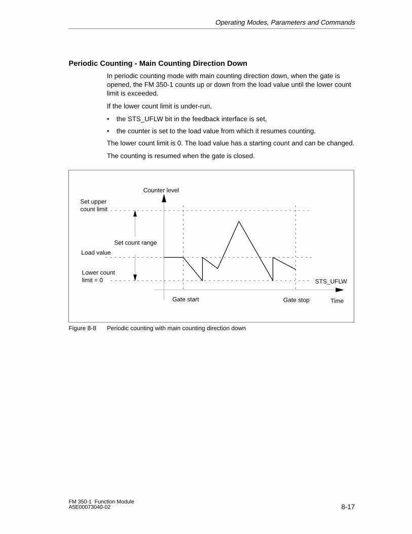
Operating Modes, Parameters and Commands
8-17FM 350-1 Function ModuleA5E00073040-02
Periodic Counting - Main Counting Direction Down
In periodic counting mode with main counting direction down, when the gate isopened, the FM 350-1 counts up or down from the load value until the lower countlimit is exceeded.
If the lower count limit is under-run,
• the STS_UFLW bit in the feedback interface is set,
• the counter is set to the load value from which it resumes counting.
The lower count limit is 0. The load value has a starting count and can be changed.
The counting is resumed when the gate is closed.
STS_UFLW
Set uppercount limit
Lower countlimit = 0
Set count range
Counter level
TimeGate start
Load value
Gate stop
Figure 8-8 Periodic counting with main counting direction down
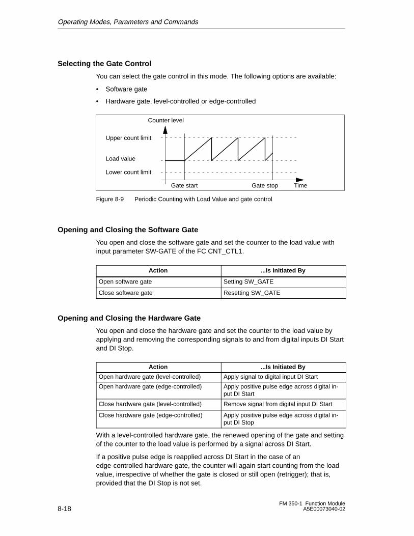
Operating Modes, Parameters and Commands
8-18FM 350-1 Function Module
A5E00073040-02
Selecting the Gate Control
You can select the gate control in this mode. The following options are available:
• Software gate
• Hardware gate, level-controlled or edge-controlled
Upper count limit
Lower count limit
Counter level
Time
Load value
Gate start Gate stop
Figure 8-9 Periodic Counting with Load Value and gate control
Opening and Closing the Software Gate
You open and close the software gate and set the counter to the load value withinput parameter SW-GATE of the FC CNT_CTL1.
Action ...Is Initiated By
Open software gate Setting SW_GATE
Close software gate Resetting SW_GATE
Opening and Closing the Hardware Gate
You open and close the hardware gate and set the counter to the load value byapplying and removing the corresponding signals to and from digital inputs DI Startand DI Stop.
Action ...Is Initiated By
Open hardware gate (level-controlled) Apply signal to digital input DI Start
Open hardware gate (edge-controlled) Apply positive pulse edge across digital in-put DI Start
Close hardware gate (level-controlled) Remove signal from digital input DI Start
Close hardware gate (edge-controlled) Apply positive pulse edge across digital in-put DI Stop
With a level-controlled hardware gate, the renewed opening of the gate and settingof the counter to the load value is performed by a signal across DI Start.
If a positive pulse edge is reapplied across DI Start in the case of anedge-controlled hardware gate, the counter will again start counting from the loadvalue, irrespective of whether the gate is closed or still open (retrigger); that is,provided that the DI Stop is not set.
Operating Modes, Parameters and Commands
8-19FM 350-1 Function ModuleA5E00073040-02
Behavior at the Count Limits
If the counter has reached the upper or lower count limit and a further count pulseis received, the counter is set
– to the other count limit when counting without a main counting direction
– to the load value when counting with a main counting direction
The gate is then closed and the count is terminated even if the SW_GATEparameter is still set or the hardware gate is still open. An appropriate status bit isset in the DB.
Count Limit Reached Status bit in the DB
Upper count limit STS_OFLW is set
Lower count limit STS_UFLW is set
Ending the Counting Operation with the Gate Stop Function
You can also end the counting operation using the gate stop function by setting theGATE_STP input parameters of the CNT_CTL1 function.
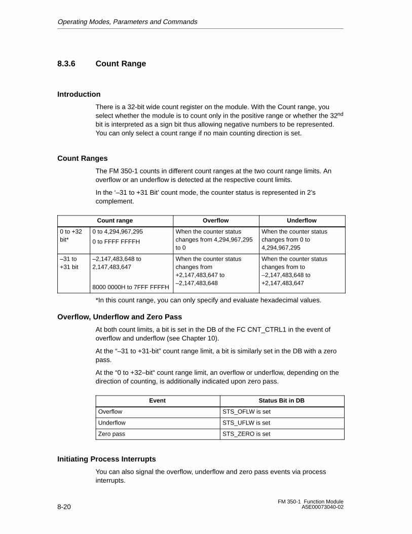
Operating Modes, Parameters and Commands
8-20FM 350-1 Function Module
A5E00073040-02
8.3.6 Count Range
Introduction
There is a 32-bit wide count register on the module. With the Count range, youselect whether the module is to count only in the positive range or whether the 32nd
bit is interpreted as a sign bit thus allowing negative numbers to be represented.You can only select a count range if no main counting direction is set.
Count Ranges
The FM 350-1 counts in different count ranges at the two count range limits. Anoverflow or an underflow is detected at the respective count limits.
In the ‘–31 to +31 Bit’ count mode, the counter status is represented in 2’scomplement.
Count range Overflow Underflow
0 to +32bit*
0 to 4,294,967,295
0 to FFFF FFFFH
When the counter statuschanges from 4,294,967,295to 0
When the counter statuschanges from 0 to4,294,967,295
–31 to+31 bit
–2,147,483,648 to2,147,483,647
8000 0000H to 7FFF FFFFH
When the counter statuschanges from+2,147,483,647 to–2,147,483,648
When the counter statuschanges from to–2,147,483,648 to+2,147,483,647
*In this count range, you can only specify and evaluate hexadecimal values.
Overflow, Underflow and Zero Pass
At both count limits, a bit is set in the DB of the FC CNT_CTRL1 in the event ofoverflow and underflow (see Chapter 10).
At the “–31 to +31-bit” count range limit, a bit is similarly set in the DB with a zeropass.
At the “0 to +32–bit“ count range limit, an overflow or underflow, depending on thedirection of counting, is additionally indicated upon zero pass.
Event Status Bit in DB
Overflow STS_OFLW is set
Underflow STS_UFLW is set
Zero pass STS_ZERO is set
Initiating Process Interrupts
You can also signal the overflow, underflow and zero pass events via processinterrupts.
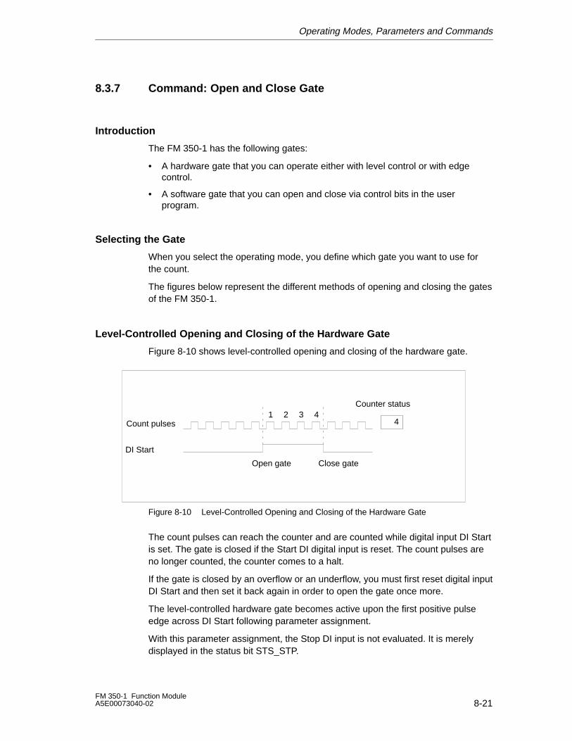
Operating Modes, Parameters and Commands
8-21FM 350-1 Function ModuleA5E00073040-02
8.3.7 Command: Open and Close Gate
Introduction
The FM 350-1 has the following gates:
• A hardware gate that you can operate either with level control or with edgecontrol.
• A software gate that you can open and close via control bits in the userprogram.
Selecting the Gate
When you select the operating mode, you define which gate you want to use forthe count.
The figures below represent the different methods of opening and closing the gatesof the FM 350-1.
Level-Controlled Opening and Closing of the Hardware Gate
Figure 8-10 shows level-controlled opening and closing of the hardware gate.
Open gate Close gate
4
Counter status
Count pulses
DI Start
1 2 3 4
Figure 8-10 Level-Controlled Opening and Closing of the Hardware Gate
The count pulses can reach the counter and are counted while digital input DI Startis set. The gate is closed if the Start DI digital input is reset. The count pulses areno longer counted, the counter comes to a halt.
If the gate is closed by an overflow or an underflow, you must first reset digital inputDI Start and then set it back again in order to open the gate once more.
The level-controlled hardware gate becomes active upon the first positive pulseedge across DI Start following parameter assignment.
With this parameter assignment, the Stop DI input is not evaluated. It is merelydisplayed in the status bit STS_STP.
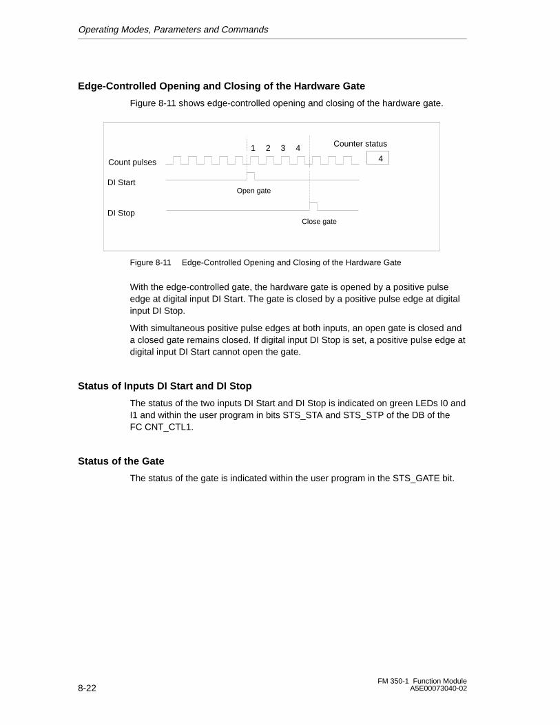
Operating Modes, Parameters and Commands
8-22FM 350-1 Function Module
A5E00073040-02
Edge-Controlled Opening and Closing of the Hardware Gate
Figure 8-11 shows edge-controlled opening and closing of the hardware gate.
4
Counter status
Count pulses
DI Start
DI Stop
Open gate
Close gate
1 2 3 4
Figure 8-11 Edge-Controlled Opening and Closing of the Hardware Gate
With the edge-controlled gate, the hardware gate is opened by a positive pulseedge at digital input DI Start. The gate is closed by a positive pulse edge at digitalinput DI Stop.
With simultaneous positive pulse edges at both inputs, an open gate is closed anda closed gate remains closed. If digital input DI Stop is set, a positive pulse edge atdigital input DI Start cannot open the gate.
Status of Inputs DI Start and DI Stop
The status of the two inputs DI Start and DI Stop is indicated on green LEDs I0 andI1 and within the user program in bits STS_STA and STS_STP of the DB of theFC CNT_CTL1.
Status of the Gate
The status of the gate is indicated within the user program in the STS_GATE bit.
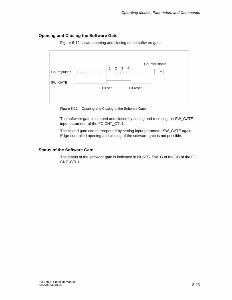
Operating Modes, Parameters and Commands
8-23FM 350-1 Function ModuleA5E00073040-02
Opening and Closing the Software Gate
Figure 8-12 shows opening and closing of the software gate.
Bit set Bit reset
4
Counter status
Count pulses
SW_GATE
1 2 3 4
Figure 8-12 Opening and Closing of the Software Gate
The software gate is opened and closed by setting and resetting the SW_GATEinput parameter of the FC CNT_CTL1.
The closed gate can be reopened by setting input parameter SW_GATE again.Edge-controlled opening and closing of the software gate is not possible.
Status of the Software Gate
The status of the software gate is indicated in bit STS_SW_G of the DB of the FCCNT_CTL1.
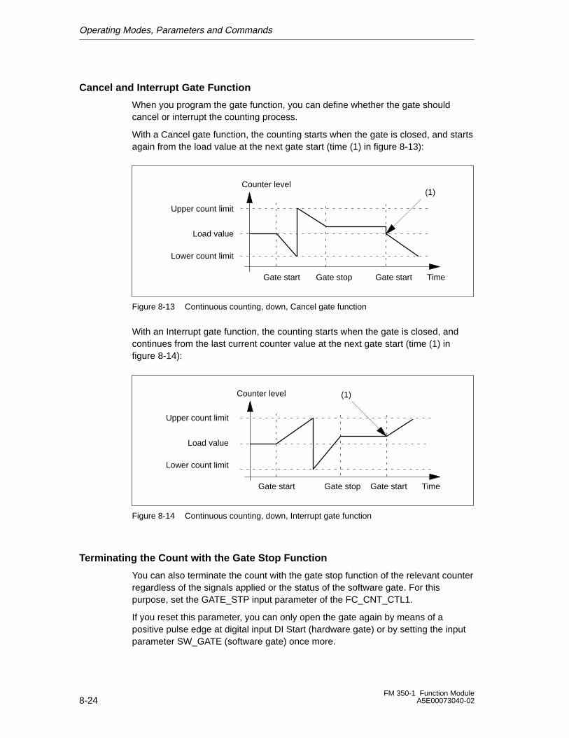
Operating Modes, Parameters and Commands
8-24FM 350-1 Function Module
A5E00073040-02
Cancel and Interrupt Gate Function
When you program the gate function, you can define whether the gate shouldcancel or interrupt the counting process.
With a Cancel gate function, the counting starts when the gate is closed, and startsagain from the load value at the next gate start (time (1) in figure 8-13):
Upper count limit
Lower count limit
Counter level
Load value
TimeGate start Gate stop Gate start
(1)
Figure 8-13 Continuous counting, down, Cancel gate function
With an Interrupt gate function, the counting starts when the gate is closed, andcontinues from the last current counter value at the next gate start (time (1) infigure 8-14):
(1)
Upper count limit
Lower count limit
Counter level
Load value
TimeGate start Gate stop Gate start
Figure 8-14 Continuous counting, down, Interrupt gate function
Terminating the Count with the Gate Stop Function
You can also terminate the count with the gate stop function of the relevant counterregardless of the signals applied or the status of the software gate. For thispurpose, set the GATE_STP input parameter of the FC_CNT_CTL1.
If you reset this parameter, you can only open the gate again by means of apositive pulse edge at digital input DI Start (hardware gate) or by setting the inputparameter SW_GATE (software gate) once more.
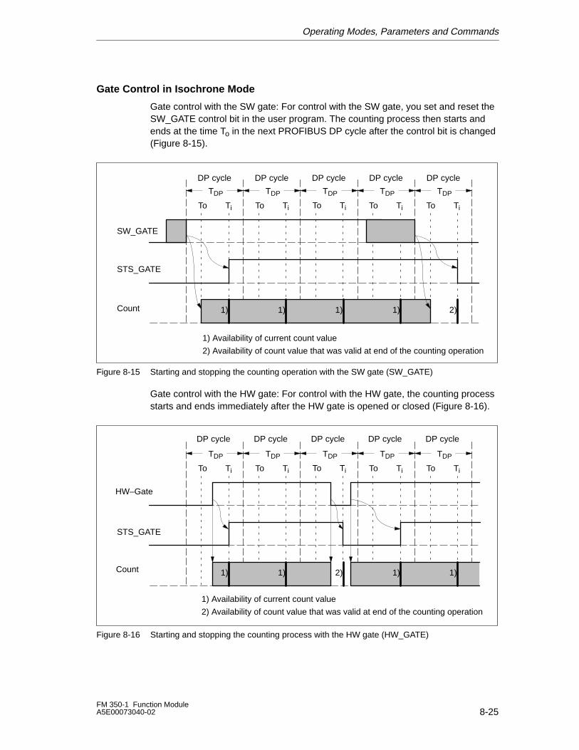
Operating Modes, Parameters and Commands
8-25FM 350-1 Function ModuleA5E00073040-02
Gate Control in Isochrone Mode
Gate control with the SW gate: For control with the SW gate, you set and reset theSW_GATE control bit in the user program. The counting process then starts andends at the time To in the next PROFIBUS DP cycle after the control bit is changed(Figure 8-15).
STS_GATE
SW_GATE
DP cycle DP cycleDP cycleDP cycle
Ti Ti
TDP TDPTDPTDPTDP
TiTi TiTo ToToTo To
DP cycle
Count 1) 1)1)1)
1) Availability of current count value
2)
2) Availability of count value that was valid at end of the counting operation
Figure 8-15 Starting and stopping the counting operation with the SW gate (SW_GATE)
Gate control with the HW gate: For control with the HW gate, the counting processstarts and ends immediately after the HW gate is opened or closed (Figure 8-16).
STS_GATE
HW–Gate
Ti Ti
TDP TDPTDPTDPTDP
TiTi TiTo ToToTo To
1) 1) 1) 1)2)
DP cycle DP cycleDP cycleDP cycle DP cycle
Count
1) Availability of current count value
2) Availability of count value that was valid at end of the counting operation
Figure 8-16 Starting and stopping the counting process with the HW gate (HW_GATE)
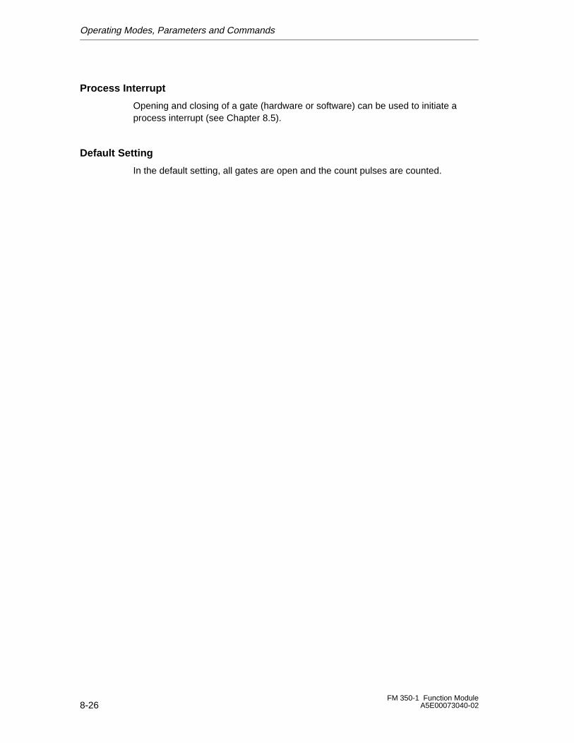
Operating Modes, Parameters and Commands
8-26FM 350-1 Function Module
A5E00073040-02
Process Interrupt
Opening and closing of a gate (hardware or software) can be used to initiate aprocess interrupt (see Chapter 8.5).
Default Setting
In the default setting, all gates are open and the count pulses are counted.
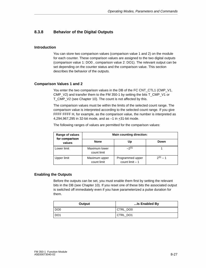
Operating Modes, Parameters and Commands
8-27FM 350-1 Function ModuleA5E00073040-02
8.3.8 Behavior of the Digital Outputs
Introduction
You can store two comparison values (comparison value 1 and 2) on the modulefor each counter. These comparison values are assigned to the two digital outputs(comparison value 1: DO0 , comparison value 2: DO1). The relevant output can beset depending on the counter status and the comparison value. This sectiondescribes the behavior of the outputs.
Comparison Values 1 and 2
You enter the two comparison values in the DB of the FC CNT_CTL1 (CMP_V1,CMP_V2) and transfer them to the FM 350-1 by setting the bits T_CMP_V1 orT_CMP_V2 (see Chapter 10). The count is not affected by this.
The comparison values must be within the limits of the selected count range. Thecomparison value is interpreted according to the selected count range. If you giveFFFF FFFF H, for example, as the comparison value, the number is interpreted as4,294,967,295 in 32-bit mode, and as –1 in +31-bit mode.
The following ranges of values are permitted for the comparison values:
Range of valuesfor comparison
Main counting direction:for compar ison
values None Up Down
Lower limit Maximum lowercount limit
–231 1
Upper limit Maximum uppercount limit
Programmed uppercount limit – 1
231 – 1
Enabling the Outputs
Before the outputs can be set, you must enable them first by setting the relevantbits in the DB (see Chapter 10). If you reset one of these bits the associated outputis switched off immediately even if you have parameterized a pulse duration forthem.
Output ...Is Enabled By
DO0 CTRL_DO0
DO1 CTRL_DO1
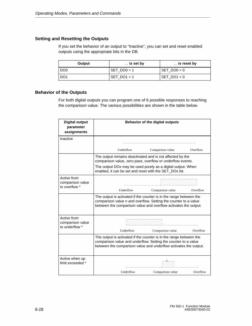
Operating Modes, Parameters and Commands
8-28FM 350-1 Function Module
A5E00073040-02
Setting and Resetting the Outputs
If you set the behavior of an output to “Inactive”, you can set and reset enabledoutputs using the appropriate bits in the DB.
Output … is set by … is reset by
DO0 SET_DO0 = 1 SET_DO0 = 0
DO1 SET_DO1 = 1 SET_DO1 = 0
Behavior of the Outputs
For both digital outputs you can program one of 6 possible responses to reachingthe comparison value. The various possibilities are shown in the table below.
Digital outputparameter
assignments
Behavior of the digital outputs
Inactive
Underflow Comparison value Overflow
The output remains deactivated and is not affected by thecomparison value, zero pass, overflow or underflow events.
The output DOx may be used purely as a digital output. Whenenabled, it can be set and reset with the SET_DOx bit.
Active fromcomparison valueto overflow *
Underflow Comparison value Overflow
The output is activated if the counter is in the range between thecomparison value n and overflow. Setting the counter to a valuebetween the comparison value and overflow activates the output.
Active fromcomparison valueto underflow *
Underflow Comparison value Overflow
The output is activated if the counter is in the range between thecomparison value and underflow. Setting the counter to a valuebetween the comparison value and underflow activates the output.
Active when uplimit exceeded *
t
Underflow Comparison value Overflow
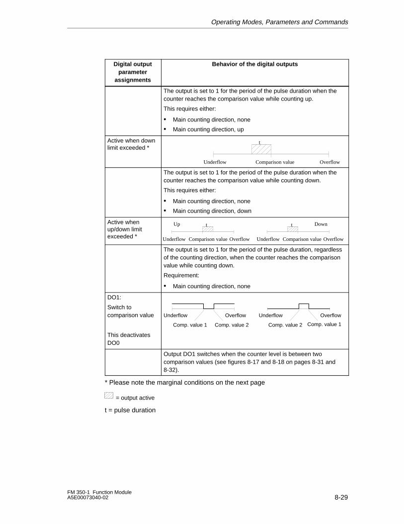
Operating Modes, Parameters and Commands
8-29FM 350-1 Function ModuleA5E00073040-02
Digital outputparameter
assignments
Behavior of the digital outputs
The output is set to 1 for the period of the pulse duration when thecounter reaches the comparison value while counting up.
This requires either:
• Main counting direction, none
• Main counting direction, up
Active when downlimit exceeded *
t
Underflow Comparison value Overflow
The output is set to 1 for the period of the pulse duration when thecounter reaches the comparison value while counting down.
This requires either:
• Main counting direction, none
• Main counting direction, down
Active whenup/down limitexceeded *
t tUp Down
Underflow Comparison value Overflow Underflow Comparison value Overflow
The output is set to 1 for the period of the pulse duration, regardlessof the counting direction, when the counter reaches the comparisonvalue while counting down.
Requirement:
• Main counting direction, none
DO1:
Switch tocomparison value
This deactivatesDO0
Underflow
Comp. value 1
Overflow
Comp. value 2
Underflow
Comp. value 2
Overflow
Comp. value 1
Output DO1 switches when the counter level is between twocomparison values (see figures 8-17 and 8-18 on pages 8-31 and8-32).
* Please note the marginal conditions on the next page
= output active
t = pulse duration
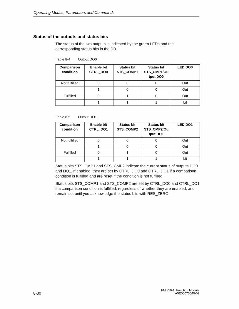
Operating Modes, Parameters and Commands
8-30FM 350-1 Function Module
A5E00073040-02
Status of the outputs and status bits
The status of the two outputs is indicated by the green LEDs and thecorresponding status bits in the DB.
Table 8-4 Output DO0
Comparisoncondition
Enable bitCTRL_DO0
Status bitSTS_COMP1
Status bitSTS_CMP1/Ou
tput DO0
LED DO0
Not fulfilled 0 0 0 Out
1 0 0 Out
Fulfilled 0 1 0 Out
1 1 1 Lit
Table 8-5 Output DO1
Comparisoncondition
Enable bitCTRL_DO1
Status bitSTS_COMP2
Status bitSTS_CMP2/Ou
tput DO1
LED DO1
Not fulfilled 0 0 0 Out
1 0 0 Out
Fulfilled 0 1 0 Out
1 1 1 Lit
Status bits STS_CMP1 and STS_CMP2 indicate the current status of outputs DO0and DO1. If enabled, they are set by CTRL_DO0 and CTRL_DO1 if a comparisoncondition is fulfilled and are reset if the condition is not fulfilled.
Status bits STS_COMP1 and STS_COMP2 are set by CTRL_DO0 and CTRL_DO1if a comparison condition is fulfilled, regardless of whether they are enabled, andremain set until you acknowledge the status bits with RES_ZERO.
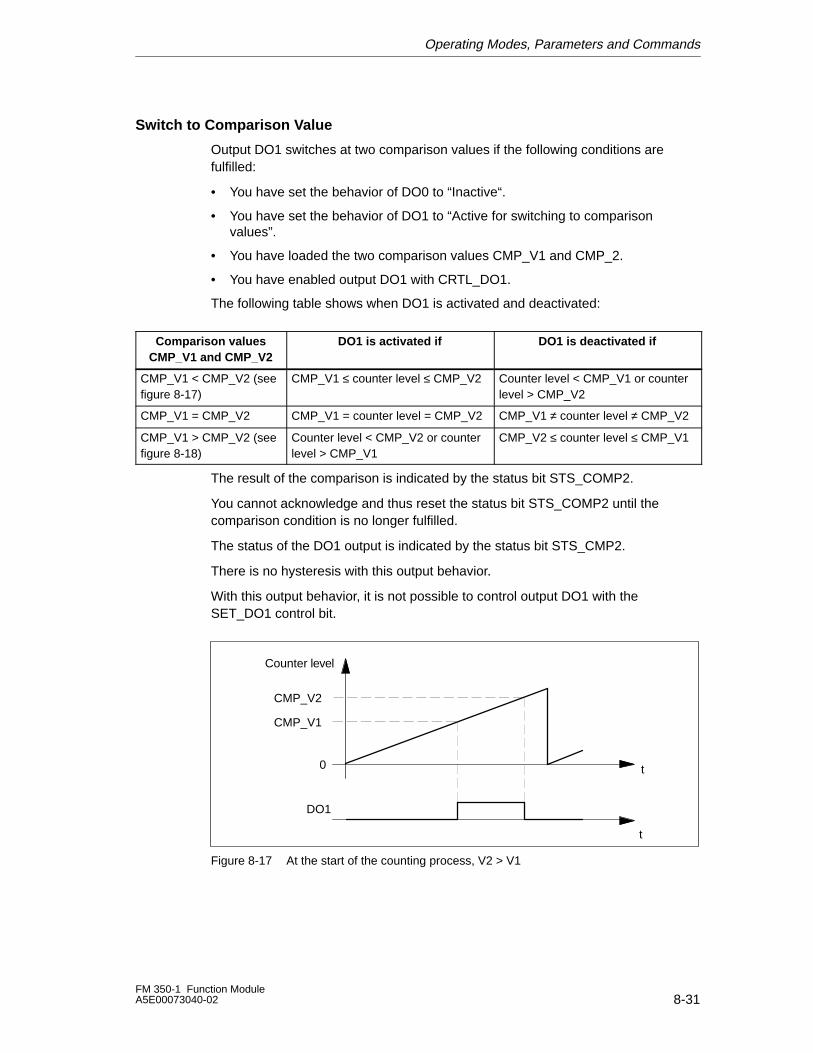
Operating Modes, Parameters and Commands
8-31FM 350-1 Function ModuleA5E00073040-02
Switch to Comparison Value
Output DO1 switches at two comparison values if the following conditions arefulfilled:
• You have set the behavior of DO0 to “Inactive“.
• You have set the behavior of DO1 to “Active for switching to comparisonvalues”.
• You have loaded the two comparison values CMP_V1 and CMP_2.
• You have enabled output DO1 with CRTL_DO1.
The following table shows when DO1 is activated and deactivated:
Comparison valuesCMP_V1 and CMP_V2
DO1 is activated if DO1 is deactivated if
CMP_V1 < CMP_V2 (seefigure 8-17)
CMP_V1 ≤ counter level ≤ CMP_V2 Counter level < CMP_V1 or counterlevel > CMP_V2
CMP_V1 = CMP_V2 CMP_V1 = counter level = CMP_V2 CMP_V1 ≠ counter level ≠ CMP_V2
CMP_V1 > CMP_V2 (seefigure 8-18)
Counter level < CMP_V2 or counterlevel > CMP_V1
CMP_V2 ≤ counter level ≤ CMP_V1
The result of the comparison is indicated by the status bit STS_COMP2.
You cannot acknowledge and thus reset the status bit STS_COMP2 until thecomparison condition is no longer fulfilled.
The status of the DO1 output is indicated by the status bit STS_CMP2.
There is no hysteresis with this output behavior.
With this output behavior, it is not possible to control output DO1 with theSET_DO1 control bit.
Counter level
t
t
CMP_V2
DO1
0
CMP_V1
Figure 8-17 At the start of the counting process, V2 > V1
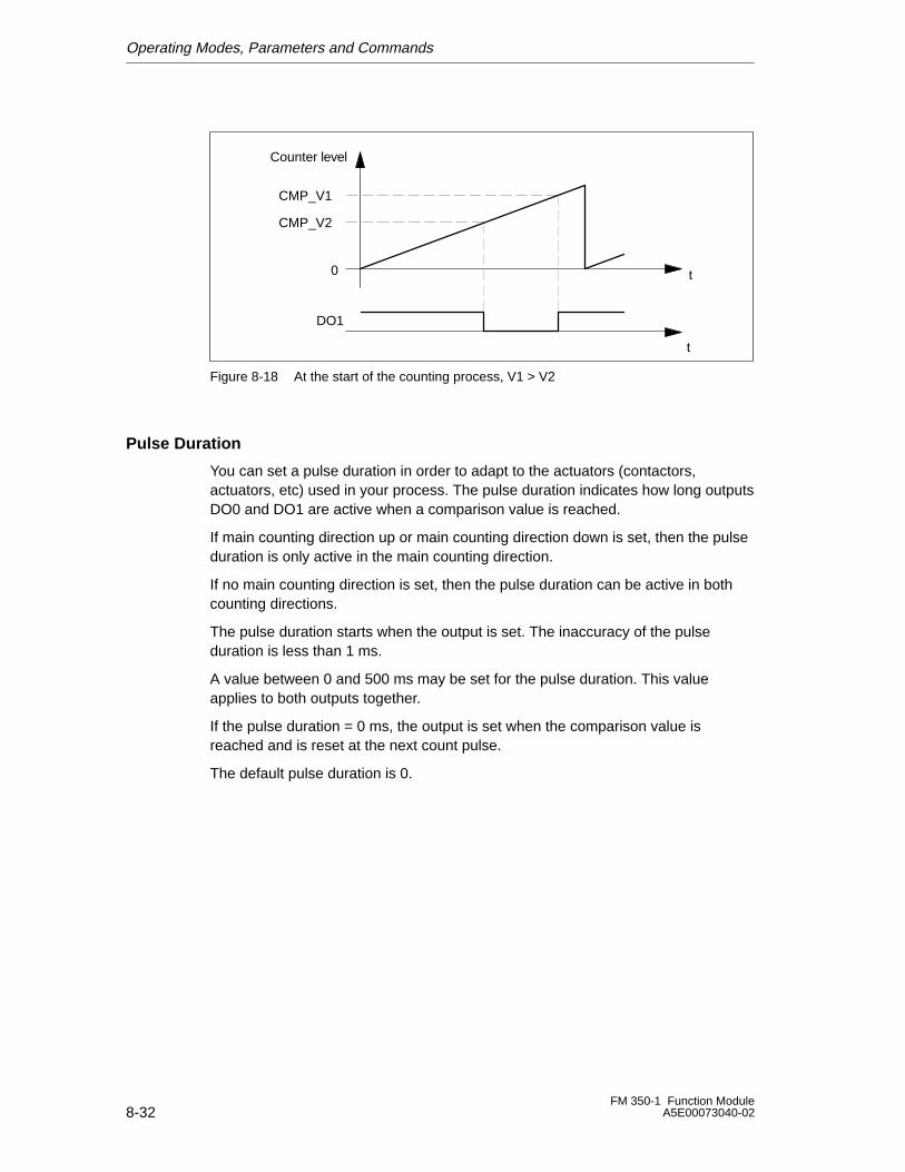
Operating Modes, Parameters and Commands
8-32FM 350-1 Function Module
A5E00073040-02
Counter level
t
t
CMP_V1
DO1
0
CMP_V2
Figure 8-18 At the start of the counting process, V1 > V2
Pulse Duration
You can set a pulse duration in order to adapt to the actuators (contactors,actuators, etc) used in your process. The pulse duration indicates how long outputsDO0 and DO1 are active when a comparison value is reached.
If main counting direction up or main counting direction down is set, then the pulseduration is only active in the main counting direction.
If no main counting direction is set, then the pulse duration can be active in bothcounting directions.
The pulse duration starts when the output is set. The inaccuracy of the pulseduration is less than 1 ms.
A value between 0 and 500 ms may be set for the pulse duration. This valueapplies to both outputs together.
If the pulse duration = 0 ms, the output is set when the comparison value isreached and is reset at the next count pulse.
The default pulse duration is 0.
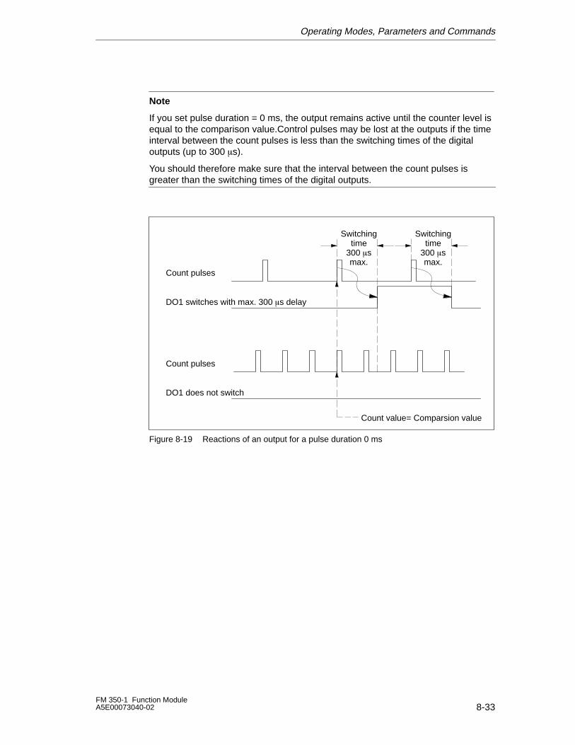
Operating Modes, Parameters and Commands
8-33FM 350-1 Function ModuleA5E00073040-02
Note
If you set pulse duration = 0 ms, the output remains active until the counter level isequal to the comparison value.Control pulses may be lost at the outputs if the timeinterval between the count pulses is less than the switching times of the digitaloutputs (up to 300 �s).
You should therefore make sure that the interval between the count pulses isgreater than the switching times of the digital outputs.
Count pulses
Count pulses
Switchingtime
300 �smax.
Count value= Comparsion value
DO1 switches with max. 300 �s delay
DO1 does not switch
Switchingtime
300 �smax.
Figure 8-19 Reactions of an output for a pulse duration 0 ms
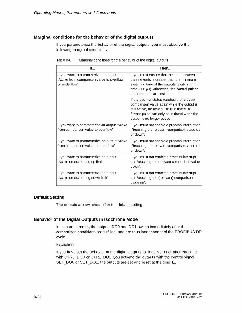
Operating Modes, Parameters and Commands
8-34FM 350-1 Function Module
A5E00073040-02
Marginal conditions for the behavior of the digital outputs
If you parameterize the behavior of the digital outputs, you must observe thefollowing marginal conditions.
Table 8-6 Marginal conditions for the behavior of the digital outputs
If... Then...
...you want to parameterize an output‘Active from comparison value to overflowor underflow’
...you must ensure that the time betweenthese events is greater than the minimumswitching time of the outputs (switchingtime: 300 �s); otherwise, the control pulsesat the outputs are lost.
If the counter status reaches the relevantcomparison value again while the output isstill active, no new pulse is initiated. Afurther pulse can only be initiated when theoutput is no longer active.
...you want to parameterize an output ‘Activefrom comparison value to overflow’
...you must not enable a process interrupt on‘Reaching the relevant comparison value upor down’.
...you want to parameterize an output Activefrom comparison value to underflow’
...you must not enable a process interrupt on‘Reaching the relevant comparison value upor down’.
...you want to parameterize an output‘Active on exceeding up limit’
...you must not enable a process interrupton ‘Reaching the relevant comparison valuedown’.
...you want to parameterize an output‘Active on exceeding down limit’
...you must not enable a process interrupton ‘Reaching the (relevant) comparisonvalue up’.
Default Setting
The outputs are switched off in the default setting.
Behavior of the Digital Outputs in Isochrone Mode
In isochrone mode, the outputs DO0 and DO1 switch immediately after thecomparison conditions are fulfilled, and are thus independent of the PROFIBUS DPcycle.
Exception:
If you have set the behavior of the digital outputs to “inactive“ and, after enablingwith CTRL_DO0 or CTRL_DO1, you activate the outputs with the control signalSET_DO0 or SET_DO1, the outputs are set and reset at the time To.
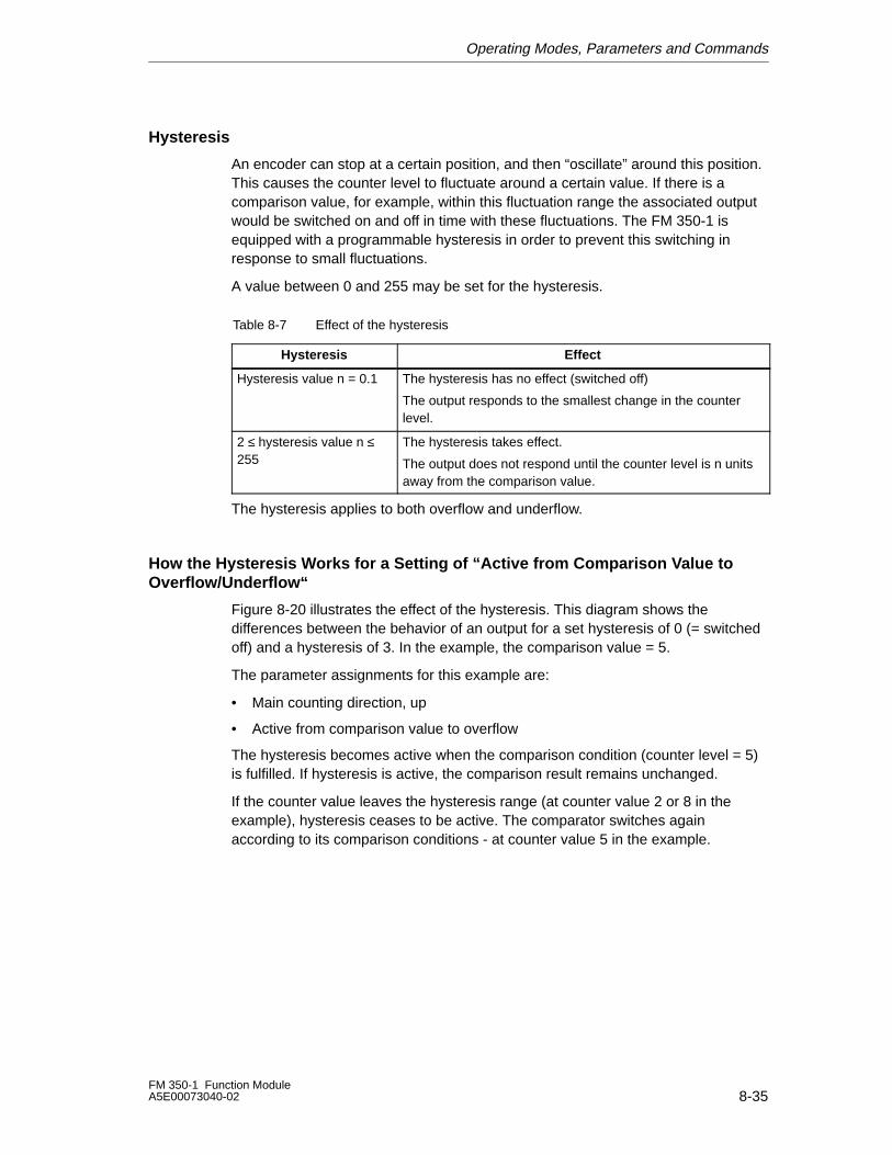
Operating Modes, Parameters and Commands
8-35FM 350-1 Function ModuleA5E00073040-02
Hysteresis
An encoder can stop at a certain position, and then “oscillate” around this position.This causes the counter level to fluctuate around a certain value. If there is acomparison value, for example, within this fluctuation range the associated outputwould be switched on and off in time with these fluctuations. The FM 350-1 isequipped with a programmable hysteresis in order to prevent this switching inresponse to small fluctuations.
A value between 0 and 255 may be set for the hysteresis.
Table 8-7 Effect of the hysteresis
Hysteresis Effect
Hysteresis value n = 0.1 The hysteresis has no effect (switched off)
The output responds to the smallest change in the counterlevel.
2 ≤ hysteresis value n ≤255
The hysteresis takes effect.
The output does not respond until the counter level is n unitsaway from the comparison value.
The hysteresis applies to both overflow and underflow.
How the Hysteresis Works for a Setting of “Active from Comparison Value toOverflow/Underflow“
Figure 8-20 illustrates the effect of the hysteresis. This diagram shows thedifferences between the behavior of an output for a set hysteresis of 0 (= switchedoff) and a hysteresis of 3. In the example, the comparison value = 5.
The parameter assignments for this example are:
• Main counting direction, up
• Active from comparison value to overflow
The hysteresis becomes active when the comparison condition (counter level = 5)is fulfilled. If hysteresis is active, the comparison result remains unchanged.
If the counter value leaves the hysteresis range (at counter value 2 or 8 in theexample), hysteresis ceases to be active. The comparator switches againaccording to its comparison conditions - at counter value 5 in the example.
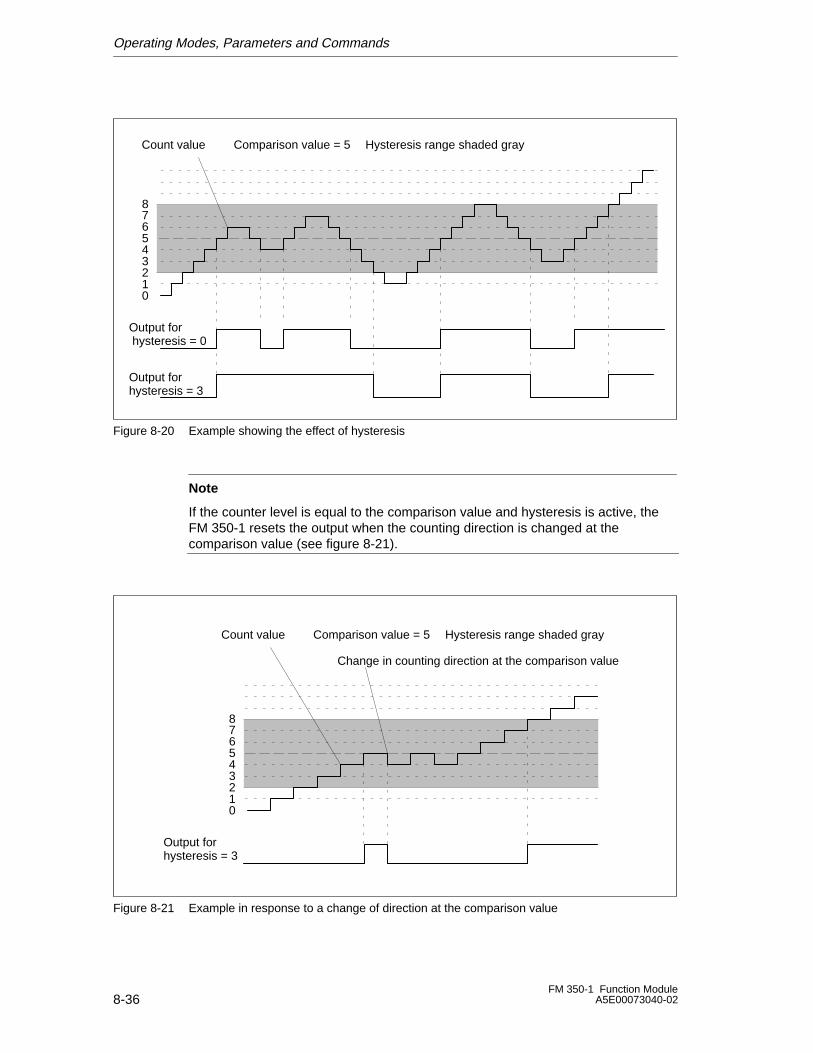
Operating Modes, Parameters and Commands
8-36FM 350-1 Function Module
A5E00073040-02
Count value
Output for hysteresis = 0
876543210
Comparison value = 5
Output for hysteresis = 3
Hysteresis range shaded gray
Figure 8-20 Example showing the effect of hysteresis
Note
If the counter level is equal to the comparison value and hysteresis is active, theFM 350-1 resets the output when the counting direction is changed at thecomparison value (see figure 8-21).
Output for hysteresis = 3
876543210
Change in counting direction at the comparison value
Count value Comparison value = 5 Hysteresis range shaded gray
Figure 8-21 Example in response to a change of direction at the comparison value
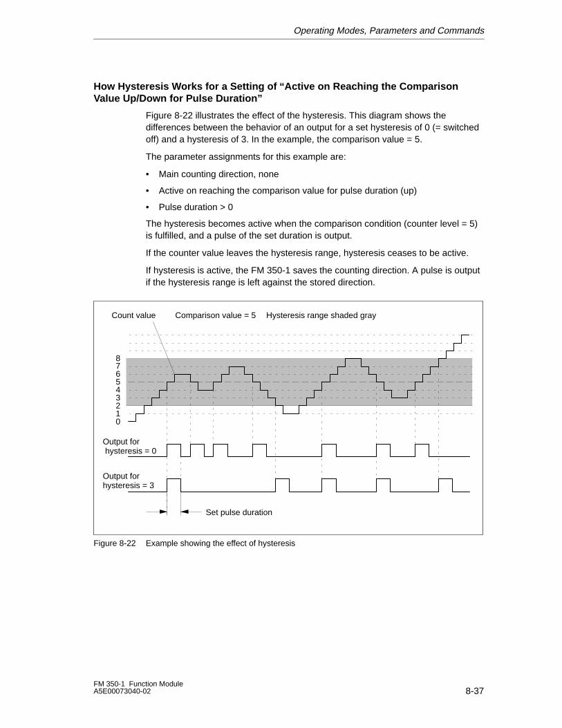
Operating Modes, Parameters and Commands
8-37FM 350-1 Function ModuleA5E00073040-02
How Hysteresis Works for a Setting of “Active on Reaching the ComparisonValue Up/Down for Pulse Duration”
Figure 8-22 illustrates the effect of the hysteresis. This diagram shows thedifferences between the behavior of an output for a set hysteresis of 0 (= switchedoff) and a hysteresis of 3. In the example, the comparison value = 5.
The parameter assignments for this example are:
• Main counting direction, none
• Active on reaching the comparison value for pulse duration (up)
• Pulse duration > 0
The hysteresis becomes active when the comparison condition (counter level = 5)is fulfilled, and a pulse of the set duration is output.
If the counter value leaves the hysteresis range, hysteresis ceases to be active.
If hysteresis is active, the FM 350-1 saves the counting direction. A pulse is outputif the hysteresis range is left against the stored direction.
876543210
Set pulse duration
Count value
Output for hysteresis = 0
Comparison value = 5
Output for hysteresis = 3
Hysteresis range shaded gray
Figure 8-22 Example showing the effect of hysteresis
Operating Modes, Parameters and Commands
8-38FM 350-1 Function Module
A5E00073040-02
8.3.9 Command: Set Counter
Introduction
If you want to start the count from a specific value (the load value), you mustparameterize the signal that is to be used to set this counter to the load value. Youcan set the counter as follows:
• With the L_DIRECT or L_PREPAR input parameter of the FC_CNT_CTL1
• With an external signal, either via the DI Set input or via DI Set in connectionwith the zero pass of the encoder
This section describes the different methods and the time sequence when setting acounter.
Load Value
Any number within the limits of the count range can be set for the count range.
The load value is interpreted according to the selected count range. If, for example,you specify FFFF FFFF H as the load value, this is interpreted as 4 294 967 295within the count range from 0 to +32 bit and as –1 within the count range from–31 to +31 bit.
Enter the load value in the DB of the CNT_CTL1 function and transfer it with theCNT_CTL1 function to the module. The counter is then set to the load value:
• directly and in preparation if input parameter L_DIRECT is set,
• in preparation only if input parameter L_PREPAR is set,
The following ranges of values are permitted for the load value:
Range of valuesf l d l
Main counting direction:for load values None Up Down
Lower limit Maximum lowercount limit
–231 + 1 2
Upper limit Maximum uppercount limit
Programmed uppercount limit –2
231 –1
Setting the Counter via the User Program
You can set a counter with the FC CNT_CTL1 using the L_DIRECT inputparameter regardless of external events. This can also be done while a count is inprogress.
If you set the counter via the FC_CNT_CTL1 call, this can initiate a processinterrupt.
Operating Modes, Parameters and Commands
8-39FM 350-1 Function ModuleA5E00073040-02
Setting the Counter with an External Signal
You can select two different external signals with which you can set a counter tothe load value:
• Input I2 only
• Input I2 and zero mark of the encoder
You use the zero mark of the encoder if you want to synchronize the counter to aspecific counter status at a specific point in your process. This achieves greateraccuracy in the loading operation.
The counter is set independently of the Count mode.
After the counter has been set with an external signal, bit STS_SYNC in the DB isset.
Note
Synchronization of a counter with zero mark only makes sense if the gate is open.If you have only enabled one count direction when setting a counter with anexternal signal, you must note that when the gate is closed the current countdirection is saved (frozen). This enables synchronization of the counter against theenabled count
Process Interrupt
Setting the counter with an external signal can be used to initiate a processinterrupt.
Setting the Counter with DI Set
The counter can be loaded with the load value by means of a rising pulse edgeacross DI Set.
By means of the tags ENSET_UP and ENSET_DN in the DB of the FC CNT_CTL1and by parameter assignment, you can set the response of the FM 350-1 to apositive pulse edge across DI Set.
Bit Behavior of the FM 350-1
ENSET_UP set The counter is only set in the case of up counting
ENSET_DN set The counter is only set in the case of down counting
ENSET_UP andENSET_DN set
The counter is set in the case of up and down counting
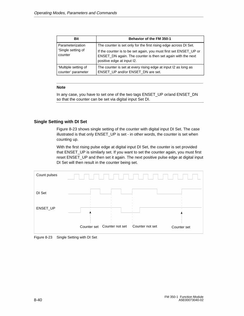
Operating Modes, Parameters and Commands
8-40FM 350-1 Function Module
A5E00073040-02
Bit Behavior of the FM 350-1
Parameterization‘Single setting ofcounter
The counter is set only for the first rising edge across DI Set.
If the counter is to be set again, you must first set ENSET_UP orENSET_DN again. The counter is then set again with the nextpositive edge at input I2.
‘Multiple setting ofcounter’ parameter
The counter is set at every rising edge at input I2 as long asENSET_UP and/or ENSET_DN are set.
Note
In any case, you have to set one of the two tags ENSET_UP or/and ENSET_DNso that the counter can be set via digital input Set DI.
Single Setting with DI Set
Figure 8-23 shows single setting of the counter with digital input DI Set. The caseillustrated is that only ENSET_UP is set - in other words, the counter is set whencounting up.
With the first rising pulse edge at digital input DI Set, the counter is set providedthat ENSET_UP is similarly set. If you want to set the counter again, you must firstreset ENSET_UP and then set it again. The next positive pulse edge at digital inputDI Set will then result in the counter being set.
Count pulses
DI Set
ENSET_UP
Counter set Counter setCounter not set Counter not set
Figure 8-23 Single Setting with DI Set
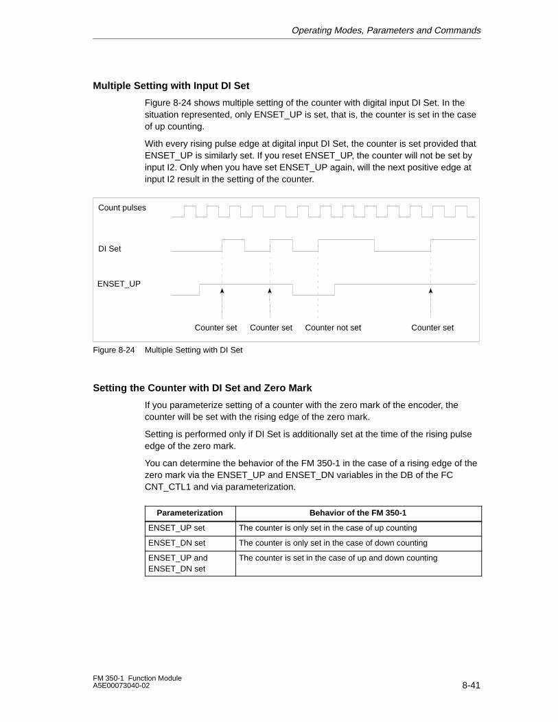
Operating Modes, Parameters and Commands
8-41FM 350-1 Function ModuleA5E00073040-02
Multiple Setting with Input DI Set
Figure 8-24 shows multiple setting of the counter with digital input DI Set. In thesituation represented, only ENSET_UP is set, that is, the counter is set in the caseof up counting.
With every rising pulse edge at digital input DI Set, the counter is set provided thatENSET_UP is similarly set. If you reset ENSET_UP, the counter will not be set byinput I2. Only when you have set ENSET_UP again, will the next positive edge atinput I2 result in the setting of the counter.
Count pulses
DI Set
ENSET_UP
Counter set Counter set Counter setCounter not set
Figure 8-24 Multiple Setting with DI Set
Setting the Counter with DI Set and Zero Mark
If you parameterize setting of a counter with the zero mark of the encoder, thecounter will be set with the rising edge of the zero mark.
Setting is performed only if DI Set is additionally set at the time of the rising pulseedge of the zero mark.
You can determine the behavior of the FM 350-1 in the case of a rising edge of thezero mark via the ENSET_UP and ENSET_DN variables in the DB of the FCCNT_CTL1 and via parameterization.
Parameterization Behavior of the FM 350-1
ENSET_UP set The counter is only set in the case of up counting
ENSET_DN set The counter is only set in the case of down counting
ENSET_UP andENSET_DN set
The counter is set in the case of up and down counting
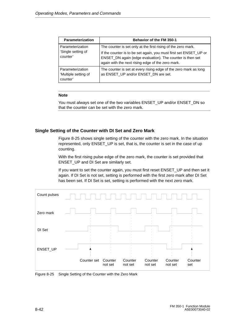
Operating Modes, Parameters and Commands
8-42FM 350-1 Function Module
A5E00073040-02
Parameterization Behavior of the FM 350-1
Parameterization‘Single setting ofcounter’
The counter is set only at the first rising of the zero mark.
If the counter is to be set again, you must first set ENSET_UP orENSET_DN again (edge evaluation). The counter is then setagain with the next rising edge of the zero mark.
Parameterization‘Multiple setting ofcounter’
The counter is set at every rising edge of the zero mark as longas ENSET_UP and/or ENSET_DN are set.
Note
You must always set one of the two variables ENSET_UP and/or ENSET_DN sothat the counter can be set with the zero mark.
Single Setting of the Counter with DI Set and Zero Mark
Figure 8-25 shows single setting of the counter with the zero mark. In the situationrepresented, only ENSET_UP is set, that is, the counter is set in the case of upcounting.
With the first rising pulse edge of the zero mark, the counter is set provided thatENSET_UP and DI Set are similarly set.
If you want to set the counter again, you must first reset ENSET_UP and then set itagain. If DI Set is not set, setting is performed with the first zero mark after DI Sethas been set. If DI Set is set, setting is performed with the next zero mark.
Zero mark
Count pulses
DI Set
ENSET_UP
Counter set Counterset
Counternot set
Counternot set
Counternot set
Counternot set
Figure 8-25 Single Setting of the Counter with the Zero Mark
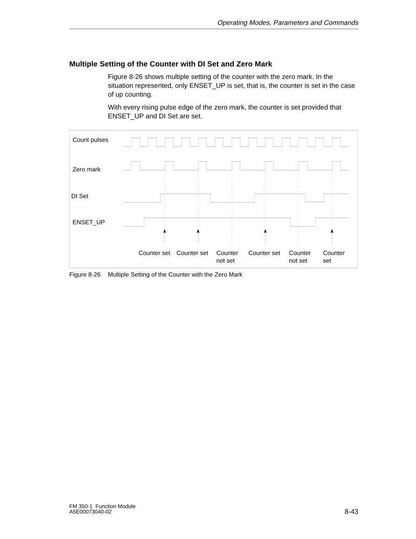
Operating Modes, Parameters and Commands
8-43FM 350-1 Function ModuleA5E00073040-02
Multiple Setting of the Counter with DI Set and Zero Mark
Figure 8-26 shows multiple setting of the counter with the zero mark. In thesituation represented, only ENSET_UP is set, that is, the counter is set in the caseof up counting.
With every rising pulse edge of the zero mark, the counter is set provided thatENSET_UP and DI Set are set.
Zero mark
Count pulses
DI Set
ENSET_UP
Counter set Counter set Counter set Counterset
Counternot set
Counternot set
Figure 8-26 Multiple Setting of the Counter with the Zero Mark
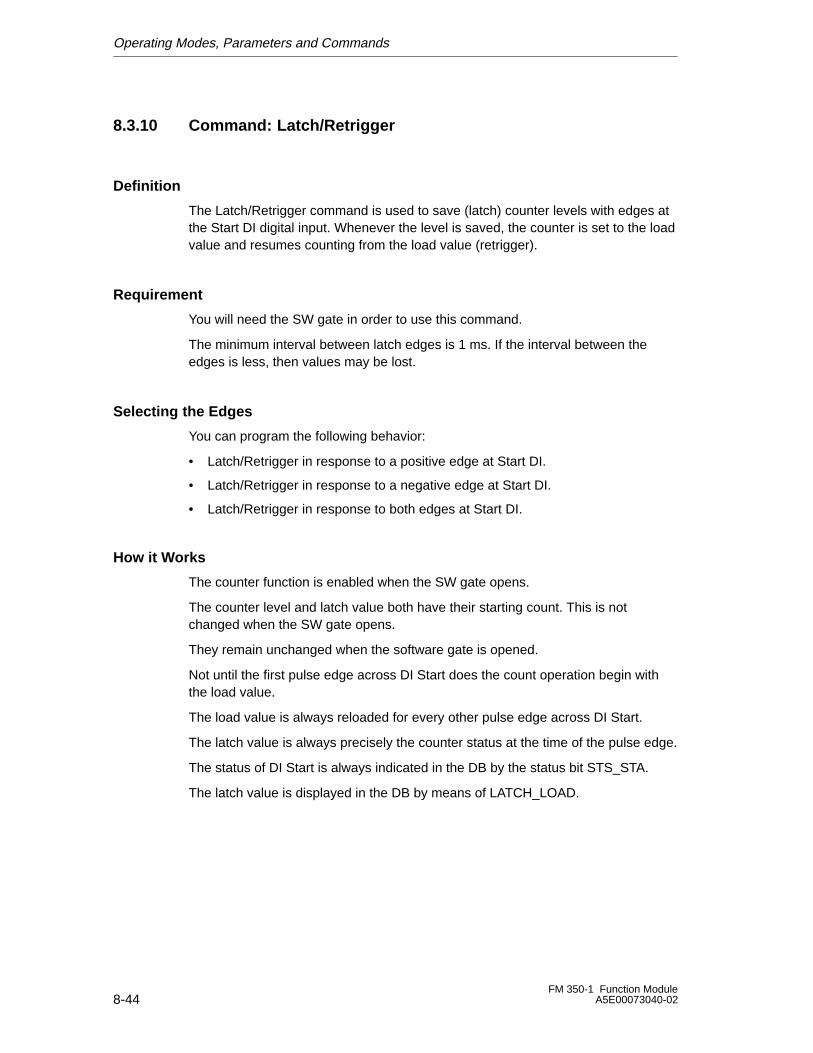
Operating Modes, Parameters and Commands
8-44FM 350-1 Function Module
A5E00073040-02
8.3.10 Command: Latch/Retrigger
Definition
The Latch/Retrigger command is used to save (latch) counter levels with edges atthe Start DI digital input. Whenever the level is saved, the counter is set to the loadvalue and resumes counting from the load value (retrigger).
Requirement
You will need the SW gate in order to use this command.
The minimum interval between latch edges is 1 ms. If the interval between theedges is less, then values may be lost.
Selecting the Edges
You can program the following behavior:
• Latch/Retrigger in response to a positive edge at Start DI.
• Latch/Retrigger in response to a negative edge at Start DI.
• Latch/Retrigger in response to both edges at Start DI.
How it Works
The counter function is enabled when the SW gate opens.
The counter level and latch value both have their starting count. This is notchanged when the SW gate opens.
They remain unchanged when the software gate is opened.
Not until the first pulse edge across DI Start does the count operation begin withthe load value.
The load value is always reloaded for every other pulse edge across DI Start.
The latch value is always precisely the counter status at the time of the pulse edge.
The status of DI Start is always indicated in the DB by the status bit STS_STA.
The latch value is displayed in the DB by means of LATCH_LOAD.
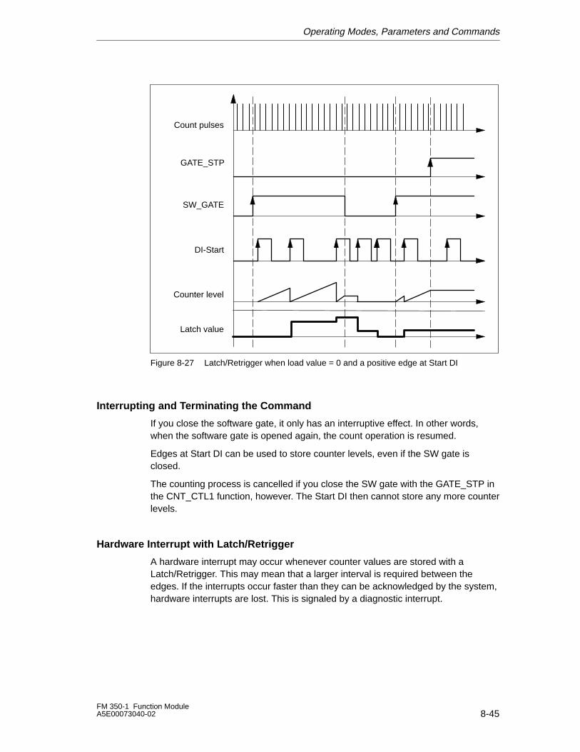
Operating Modes, Parameters and Commands
8-45FM 350-1 Function ModuleA5E00073040-02
Count pulses
GATE_STP
SW_GATE
DI-Start
Counter level
Latch value
Figure 8-27 Latch/Retrigger when load value = 0 and a positive edge at Start DI
Interrupting and Terminating the Command
If you close the software gate, it only has an interruptive effect. In other words,when the software gate is opened again, the count operation is resumed.
Edges at Start DI can be used to store counter levels, even if the SW gate isclosed.
The counting process is cancelled if you close the SW gate with the GATE_STP inthe CNT_CTL1 function, however. The Start DI then cannot store any more counterlevels.
Hardware Interrupt with Latch/Retrigger
A hardware interrupt may occur whenever counter values are stored with aLatch/Retrigger. This may mean that a larger interval is required between theedges. If the interrupts occur faster than they can be acknowledged by the system,hardware interrupts are lost. This is signaled by a diagnostic interrupt.
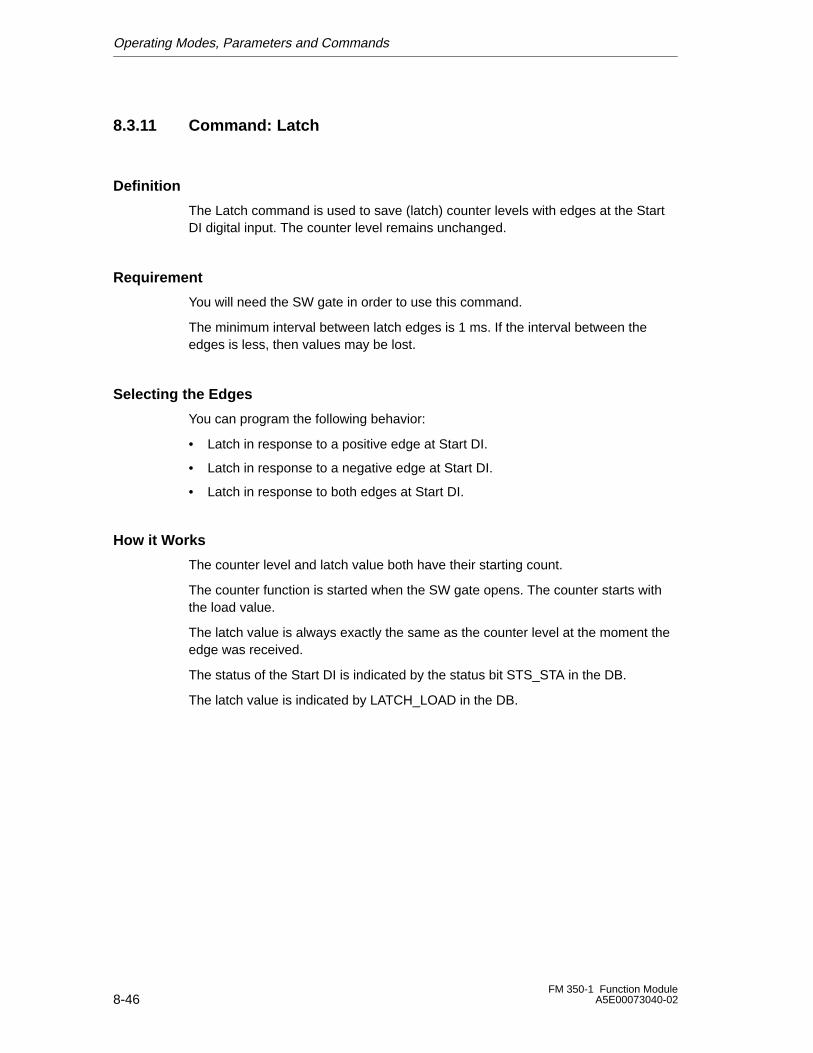
Operating Modes, Parameters and Commands
8-46FM 350-1 Function Module
A5E00073040-02
8.3.11 Command: Latch
Definition
The Latch command is used to save (latch) counter levels with edges at the StartDI digital input. The counter level remains unchanged.
Requirement
You will need the SW gate in order to use this command.
The minimum interval between latch edges is 1 ms. If the interval between theedges is less, then values may be lost.
Selecting the Edges
You can program the following behavior:
• Latch in response to a positive edge at Start DI.
• Latch in response to a negative edge at Start DI.
• Latch in response to both edges at Start DI.
How it Works
The counter level and latch value both have their starting count.
The counter function is started when the SW gate opens. The counter starts withthe load value.
The latch value is always exactly the same as the counter level at the moment theedge was received.
The status of the Start DI is indicated by the status bit STS_STA in the DB.
The latch value is indicated by LATCH_LOAD in the DB.
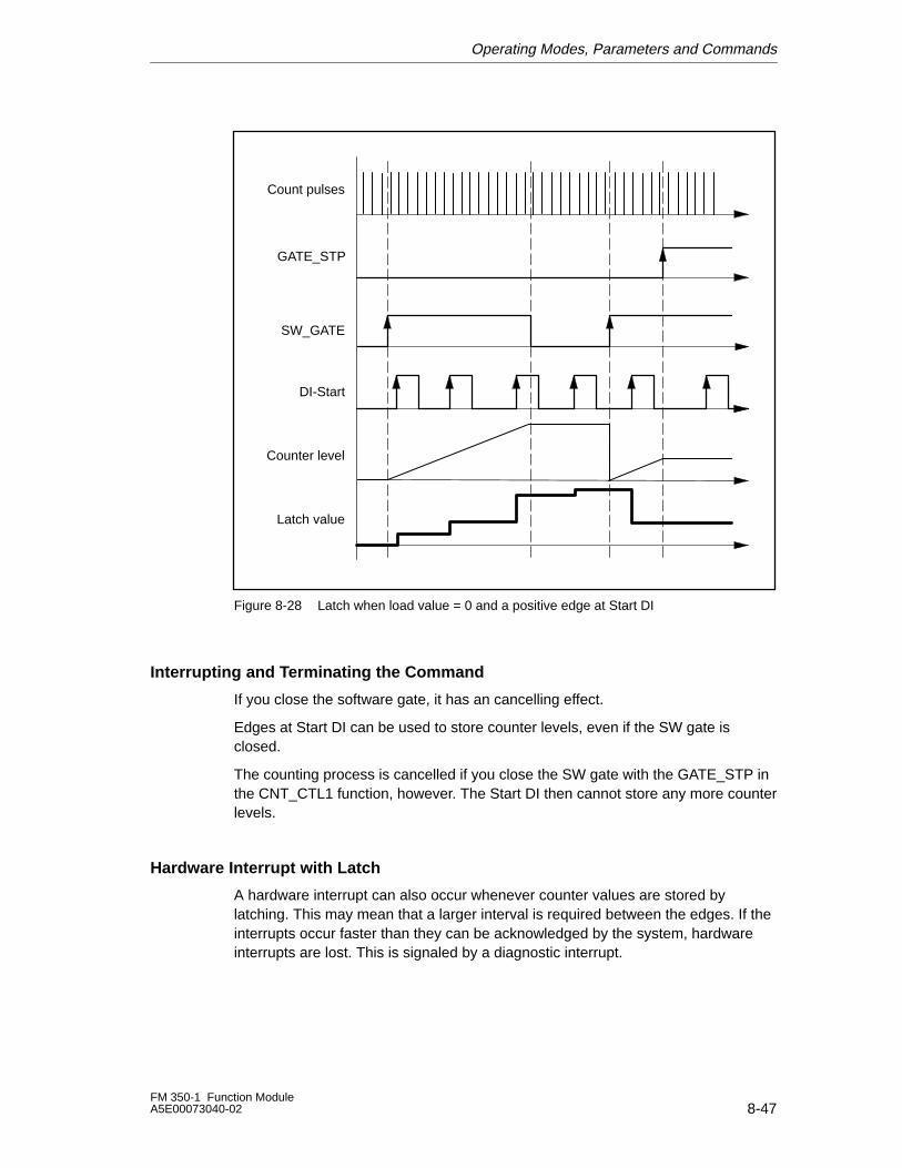
Operating Modes, Parameters and Commands
8-47FM 350-1 Function ModuleA5E00073040-02
Count pulses
SW_GATE
DI-Start
Counter level
Latch value
GATE_STP
Figure 8-28 Latch when load value = 0 and a positive edge at Start DI
Interrupting and Terminating the Command
If you close the software gate, it has an cancelling effect.
Edges at Start DI can be used to store counter levels, even if the SW gate isclosed.
The counting process is cancelled if you close the SW gate with the GATE_STP inthe CNT_CTL1 function, however. The Start DI then cannot store any more counterlevels.
Hardware Interrupt with Latch
A hardware interrupt can also occur whenever counter values are stored bylatching. This may mean that a larger interval is required between the edges. If theinterrupts occur faster than they can be acknowledged by the system, hardwareinterrupts are lost. This is signaled by a diagnostic interrupt.
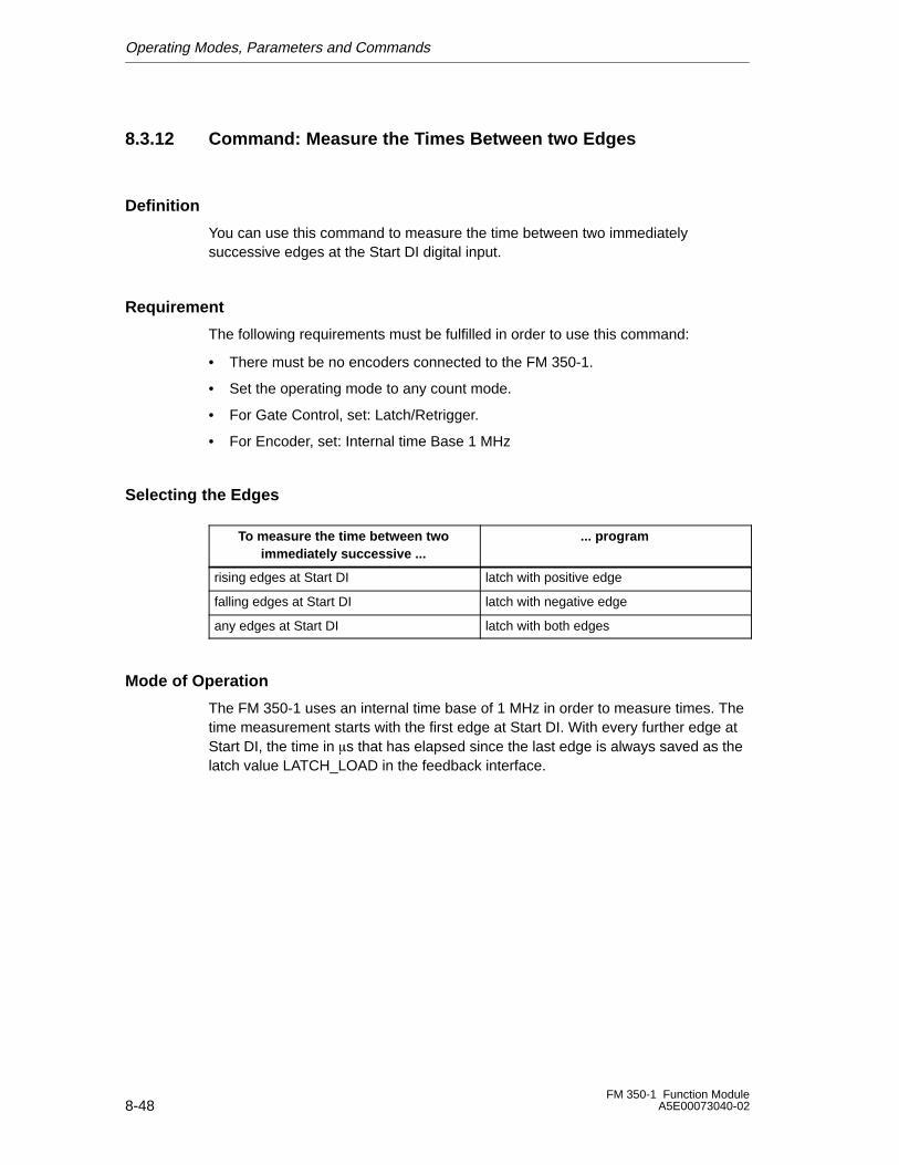
Operating Modes, Parameters and Commands
8-48FM 350-1 Function Module
A5E00073040-02
8.3.12 Command: Measure the Times Between two Edges
Definition
You can use this command to measure the time between two immediatelysuccessive edges at the Start DI digital input.
Requirement
The following requirements must be fulfilled in order to use this command:
• There must be no encoders connected to the FM 350-1.
• Set the operating mode to any count mode.
• For Gate Control, set: Latch/Retrigger.
• For Encoder, set: Internal time Base 1 MHz
Selecting the Edges
To measure the time between twoimmediately successive ...
... program
rising edges at Start DI latch with positive edge
falling edges at Start DI latch with negative edge
any edges at Start DI latch with both edges
Mode of Operation
The FM 350-1 uses an internal time base of 1 MHz in order to measure times. Thetime measurement starts with the first edge at Start DI. With every further edge atStart DI, the time in �s that has elapsed since the last edge is always saved as thelatch value LATCH_LOAD in the feedback interface.
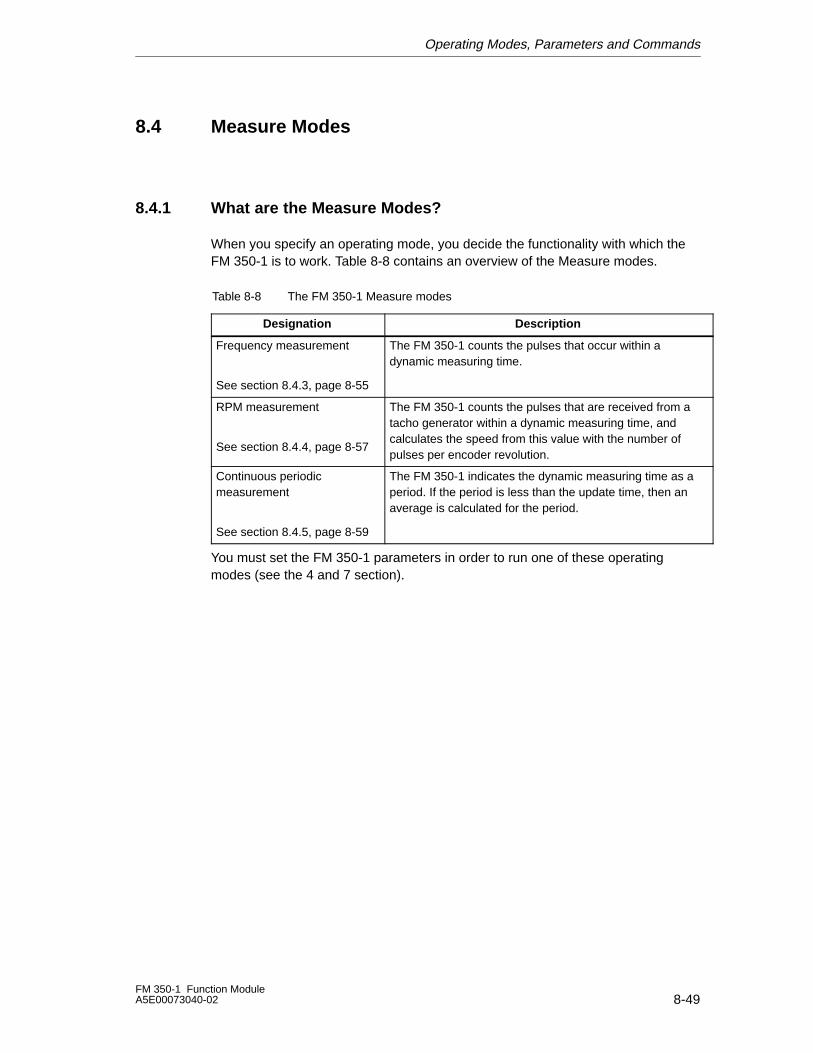
Operating Modes, Parameters and Commands
8-49FM 350-1 Function ModuleA5E00073040-02
8.4 Measure Modes
8.4.1 What are the Measure Modes?
When you specify an operating mode, you decide the functionality with which theFM 350-1 is to work. Table 8-8 contains an overview of the Measure modes.
Table 8-8 The FM 350-1 Measure modes
Designation Description
Frequency measurement
See section 8.4.3, page 8-55
The FM 350-1 counts the pulses that occur within adynamic measuring time.
RPM measurement
See section 8.4.4, page 8-57
The FM 350-1 counts the pulses that are received from atacho generator within a dynamic measuring time, andcalculates the speed from this value with the number ofpulses per encoder revolution.
Continuous periodicmeasurement
See section 8.4.5, page 8-59
The FM 350-1 indicates the dynamic measuring time as aperiod. If the period is less than the update time, then anaverage is calculated for the period.
You must set the FM 350-1 parameters in order to run one of these operatingmodes (see the 4 and 7 section).
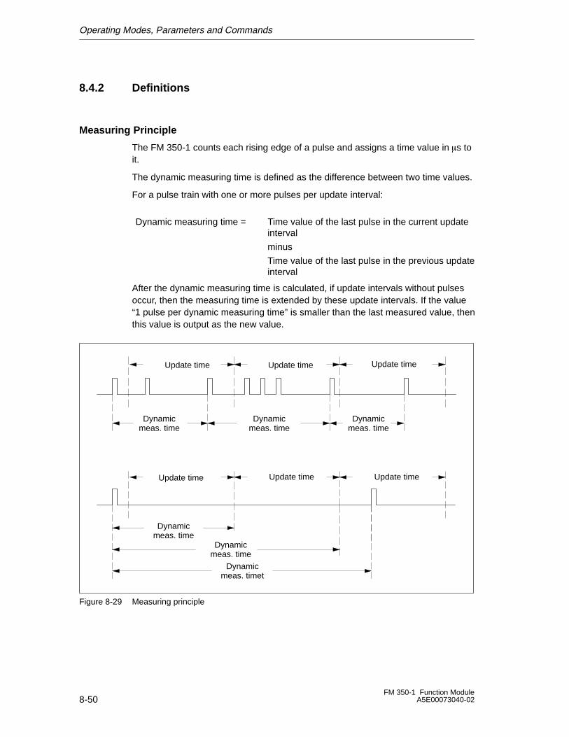
Operating Modes, Parameters and Commands
8-50FM 350-1 Function Module
A5E00073040-02
8.4.2 Definitions
Measuring Principle
The FM 350-1 counts each rising edge of a pulse and assigns a time value in �s toit.
The dynamic measuring time is defined as the difference between two time values.
For a pulse train with one or more pulses per update interval:
Dynamic measuring time = Time value of the last pulse in the current updateinterval
minus
Time value of the last pulse in the previous updateinterval
After the dynamic measuring time is calculated, if update intervals without pulsesoccur, then the measuring time is extended by these update intervals. If the value“1 pulse per dynamic measuring time” is smaller than the last measured value, thenthis value is output as the new value.
Update time Update timeUpdate time
Dynamicmeas. time
Dynamicmeas. time
Dynamicmeas. time
Update time Update timeUpdate time
Dynamicmeas. time
Dynamicmeas. timet
Dynamicmeas. time
Figure 8-29 Measuring principle
Operating Modes, Parameters and Commands
8-51FM 350-1 Function ModuleA5E00073040-02
Measurement Sequence
The FM 350-1 measures continuously. When you assign the parameters, youspecify an update time.
The value “-1” is returned in the time up to the end of the first elapsed update time.The first update time starts when the gate is opened.
The continuous measurement starts when the gate is opened with the first pulse ofthe pulse train to be measured. The first measured value can be calculated noearlier than after the second pulse.
Whenever the update time expires, a measured value is output at the feedbackinterface (frequency, period or speed). The end of a measurement is signaled bythe STS_COMP1 status bit. This bit is reset by the RES_ZERO andSTS_RES_ZERO bits using the complete acknowledgement principle.
If a change of direction occurs during an update time, the measured value is notdetermined for this measurement period. You can respond to any irregularities inthe process by evaluating the feedback bit STS_DIR (direction evaluation).
Figure 8-30 illustrates the principle of continuous measurement with reference to afrequency measurement.
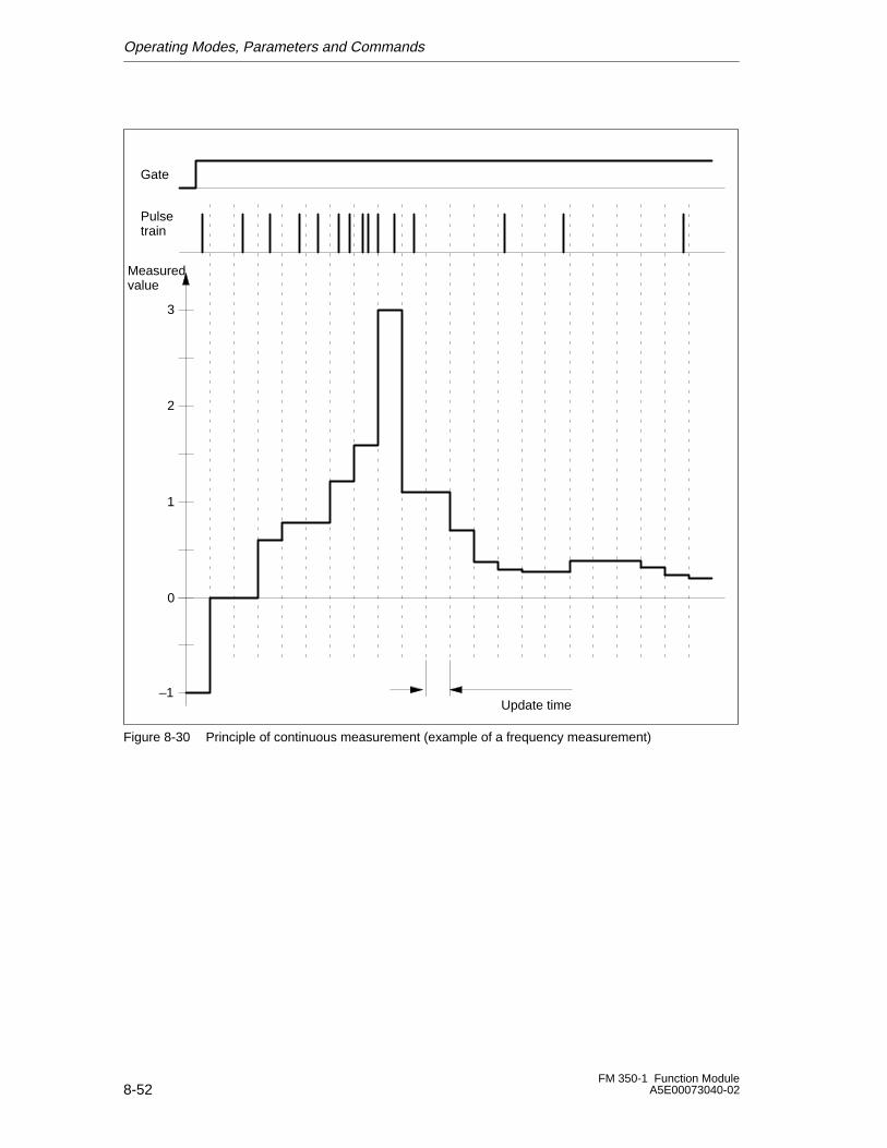
Operating Modes, Parameters and Commands
8-52FM 350-1 Function Module
A5E00073040-02
Measuredvalue
Pulsetrain
0
1
2
3
–1Update time
Gate
Figure 8-30 Principle of continuous measurement (example of a frequency measurement)
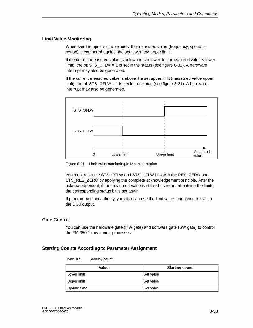
Operating Modes, Parameters and Commands
8-53FM 350-1 Function ModuleA5E00073040-02
Limit Value Monitoring
Whenever the update time expires, the measured value (frequency, speed orperiod) is compared against the set lower and upper limit.
If the current measured value is below the set lower limit (measured value < lowerlimit), the bit STS_UFLW = 1 is set in the status (see figure 8-31). A hardwareinterrupt may also be generated.
If the current measured value is above the set upper limit (measured value upperlimit), the bit STS_OFLW = 1 is set in the status (see figure 8-31). A hardwareinterrupt may also be generated.
Lower limit Upper limitMeasuredvalue0
STS_OFLW
STS_UFLW
Figure 8-31 Limit value monitoring in Measure modes
You must reset the STS_OFLW and STS_UFLW bits with the RES_ZERO andSTS_RES_ZERO by applying the complete acknowledgement principle. After theacknowledgement, if the measured value is still or has returned outside the limits,the corresponding status bit is set again.
If programmed accordingly, you also can use the limit value monitoring to switchthe DO0 output.
Gate Control
You can use the hardware gate (HW gate) and software gate (SW gate) to controlthe FM 350-1 measuring processes.
Starting Counts According to Parameter Assignment
Table 8-9 Starting count
Value Starting count
Lower limit Set value
Upper limit Set value
Update time Set value
Operating Modes, Parameters and Commands
8-54FM 350-1 Function Module
A5E00073040-02
Isochrone Mode
In isochrone mode, the FM 350-1 accepts the control signals from the controlinterface at time To in every PROFIBUS DP cycle. As a result, all the controllers runin isochrone mode and take effect at the time To. The response to the controller isreturned in the same PROFIBUS DP cycle.
The FM 350-1 provides a measured value and the status bits at time Ti in everyPROFIBUS DP cycle.
Each measurement starts and ends at time Ti.
Note
In non-isochrone mode, you can specify the update time in integer multiples of10 ms, compared to integer multiples of the PROFIBUS DP cycle time in isochronemode, so you must always adapt the Update time parameter when you switchbetween the two modes if you wish to retain the actual update time. See alsotables 8-11, 8-12 and 8-13 on pages 8-55, 8-57 and 8-59.
What are the Commands?
You can apply the following commands to the FM 350-1 measuring process.
Table 8-10 The FM 350-1 commands
Designation Description
Open and close gate The measuring process starts when a gate opens and endswhen it closes.
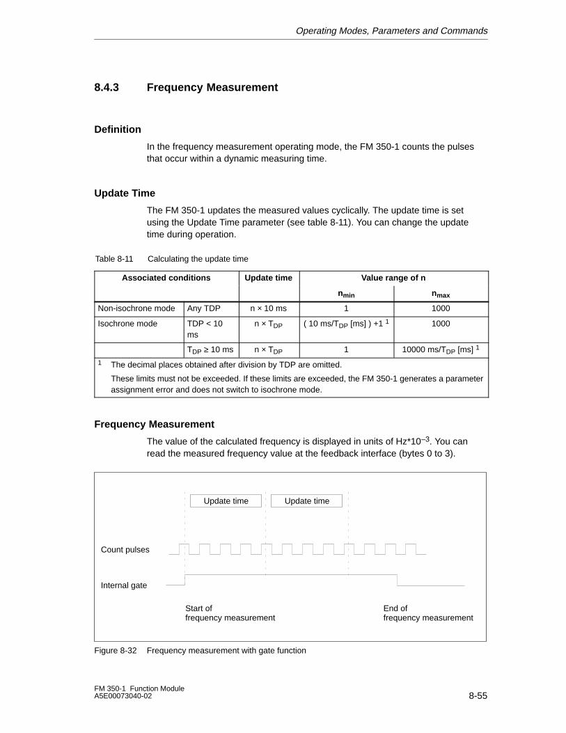
Operating Modes, Parameters and Commands
8-55FM 350-1 Function ModuleA5E00073040-02
8.4.3 Frequency Measurement
Definition
In the frequency measurement operating mode, the FM 350-1 counts the pulsesthat occur within a dynamic measuring time.
Update Time
The FM 350-1 updates the measured values cyclically. The update time is setusing the Update Time parameter (see table 8-11). You can change the updatetime during operation.
Table 8-11 Calculating the update time
Associated conditions Update time Value range of n
nmin nmax
Non-isochrone mode Any TDP n × 10 ms 1 1000
Isochrone mode TDP < 10ms
n × TDP ( 10 ms/TDP [ms] ) +1 1 1000
TDP ≥ 10 ms n × TDP 1 10000 ms/TDP [ms] 1
1 The decimal places obtained after division by TDP are omitted.
These limits must not be exceeded. If these limits are exceeded, the FM 350-1 generates a parameterassignment error and does not switch to isochrone mode.
Frequency Measurement
The value of the calculated frequency is displayed in units of Hz*10–3. You canread the measured frequency value at the feedback interface (bytes 0 to 3).
Count pulses
Internal gate
Start offrequency measurement
Update time
End offrequency measurement
Update time
Figure 8-32 Frequency measurement with gate function
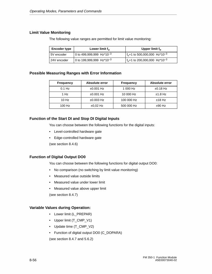
Operating Modes, Parameters and Commands
8-56FM 350-1 Function Module
A5E00073040-02
Limit Value Monitoring
The following value ranges are permitted for limit value monitoring:
Encoder type Lower limit f u Upper limit f o
5V encoder 0 to 499,999,999 Hz*10–3 fu+1 to 500,000,000 Hz*10–3
24V encoder 0 to 199,999,999 Hz*10–3 fu+1 to 200,000,000 Hz*10–3
Possible Measuring Ranges with Error Information
Frequency Absolute error Frequency Absolute error
0.1 Hz ±0.001 Hz 1 000 Hz ±0.18 Hz
1 Hz ±0.001 Hz 10 000 Hz ±1.8 Hz
10 Hz ±0.003 Hz 100 000 Hz ±18 Hz
100 Hz ±0,02 Hz 500 000 Hz ±90 Hz
Function of the Start DI and Stop DI Digital Inputs
You can choose between the following functions for the digital inputs:
• Level-controlled hardware gate
• Edge-controlled hardware gate
(see section 8.4.6)
Function of Digital Output DO0
You can choose between the following functions for digital output DO0:
• No comparison (no switching by limit value monitoring)
• Measured value outside limits
• Measured value under lower limit
• Measured value above upper limit
(see section 8.4.7)
Variable Values during Operation:
• Lower limit (L_PREPAR)
• Upper limit (T_CMP_V1)
• Update time (T_CMP_V2)
• Function of digital output DO0 (C_DOPARA)
(see section 8.4.7 and 5.6.2)
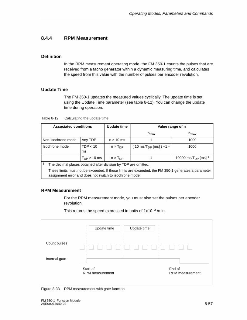
Operating Modes, Parameters and Commands
8-57FM 350-1 Function ModuleA5E00073040-02
8.4.4 RPM Measurement
Definition
In the RPM measurement operating mode, the FM 350-1 counts the pulses that arereceived from a tacho generator within a dynamic measuring time, and calculatesthe speed from this value with the number of pulses per encoder revolution.
Update Time
The FM 350-1 updates the measured values cyclically. The update time is setusing the Update Time parameter (see table 8-12). You can change the updatetime during operation.
Table 8-12 Calculating the update time
Associated conditions Update time Value range of n
nmin nmax
Non-isochrone mode Any TDP n × 10 ms 1 1000
Isochrone mode TDP < 10ms
n × TDP ( 10 ms/TDP [ms] ) +1 1 1000
TDP ≥ 10 ms n × TDP 1 10000 ms/TDP [ms] 1
1 The decimal places obtained after division by TDP are omitted.
These limits must not be exceeded. If these limits are exceeded, the FM 350-1 generates a parameterassignment error and does not switch to isochrone mode.
RPM Measurement
For the RPM measurement mode, you must also set the pulses per encoderrevolution.
This returns the speed expressed in units of 1x10⁻³ /min.
Update timeUpdate time
Count pulses
Internal gate
Start ofRPM measurement
End ofRPM measurement
Figure 8-33 RPM measurement with gate function
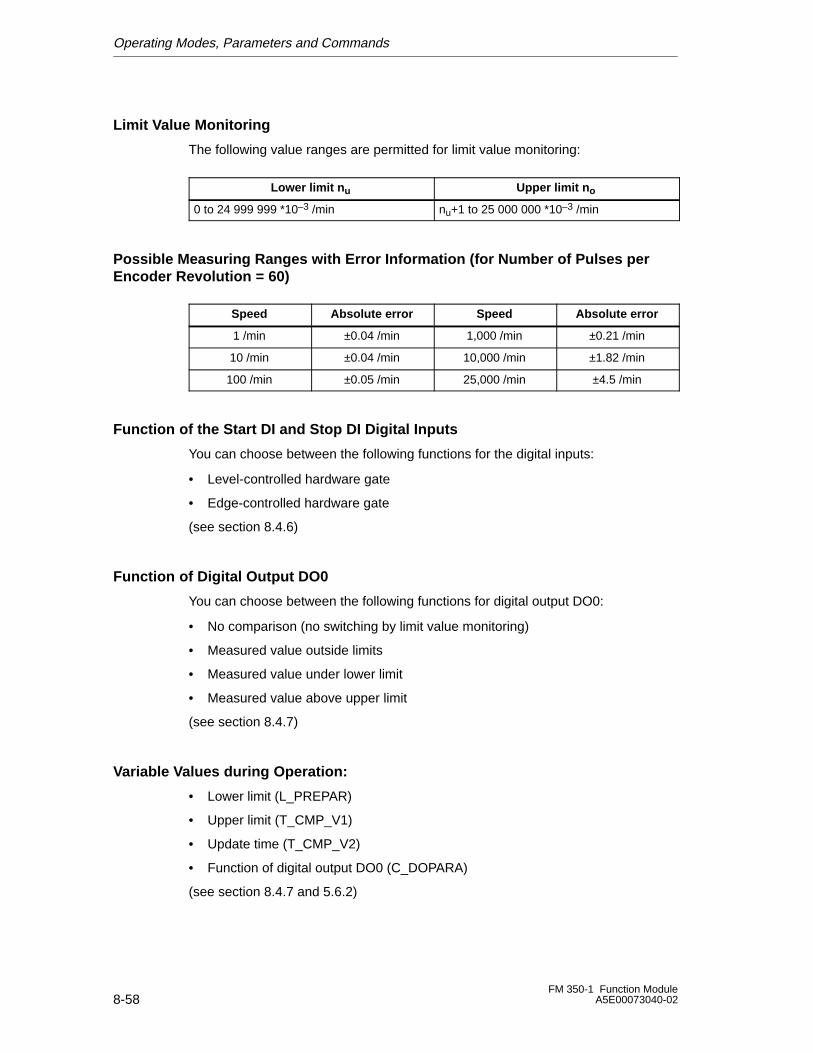
Operating Modes, Parameters and Commands
8-58FM 350-1 Function Module
A5E00073040-02
Limit Value Monitoring
The following value ranges are permitted for limit value monitoring:
Lower limit n u Upper limit n o
0 to 24 999 999 *10–3 /min nu+1 to 25 000 000 *10–3 /min
Possible Measuring Ranges with Error Information (for Number of Pulses perEncoder Revolution = 60)
Speed Absolute error Speed Absolute error
1 /min ±0.04 /min 1,000 /min ±0.21 /min
10 /min ±0.04 /min 10,000 /min ±1.82 /min
100 /min ±0.05 /min 25,000 /min ±4.5 /min
Function of the Start DI and Stop DI Digital Inputs
You can choose between the following functions for the digital inputs:
• Level-controlled hardware gate
• Edge-controlled hardware gate
(see section 8.4.6)
Function of Digital Output DO0
You can choose between the following functions for digital output DO0:
• No comparison (no switching by limit value monitoring)
• Measured value outside limits
• Measured value under lower limit
• Measured value above upper limit
(see section 8.4.7)
Variable Values during Operation:
• Lower limit (L_PREPAR)
• Upper limit (T_CMP_V1)
• Update time (T_CMP_V2)
• Function of digital output DO0 (C_DOPARA)
(see section 8.4.7 and 5.6.2)

Operating Modes, Parameters and Commands
8-59FM 350-1 Function ModuleA5E00073040-02
8.4.5 Continuous Periodic Measurement
Definition
In the continuous periodic measurement operating mode, the FM 350-1 indicatesthe dynamic measuring time as a period. If the period is less than the update time,then an average is calculated for the period.
Update Time
The FM 350-1 updates the measured values cyclically. The update time is setusing the Update Time parameter (see table 8-13). You can change the updatetime during operation.
Table 8-13 Calculating the update time
Associated conditions Update time Value range of n
nmin nmax
Non-isochrone mode Any TDP n × 10 ms 1 12000
Isochrone mode TDP < 10ms
n × TDP ( 10 ms/TDP [ms] ) +1 1 12000
TDP ≥ 10 ms n × TDP 1 120000 ms/TDP [ms] 1
1 The decimal places obtained after division by TDP are omitted.
These limits must not be exceeded. If these limits are exceeded, the FM 350-1 generates a parameterassignment error and does not switch to isochrone mode.
Continuous Periodic Measurement
The value of the calculated period is displayed in units of 1 �s and 1/16 �s. You canread the measured period at the feedback interface (bytes 0 to 3).
Period
Update timeUpdate time
Count pulses
Internal gate
Start of continuousperiodic measurement
End of continuousperiodic measurement
Figure 8-34 Periodic measurement of the gate function
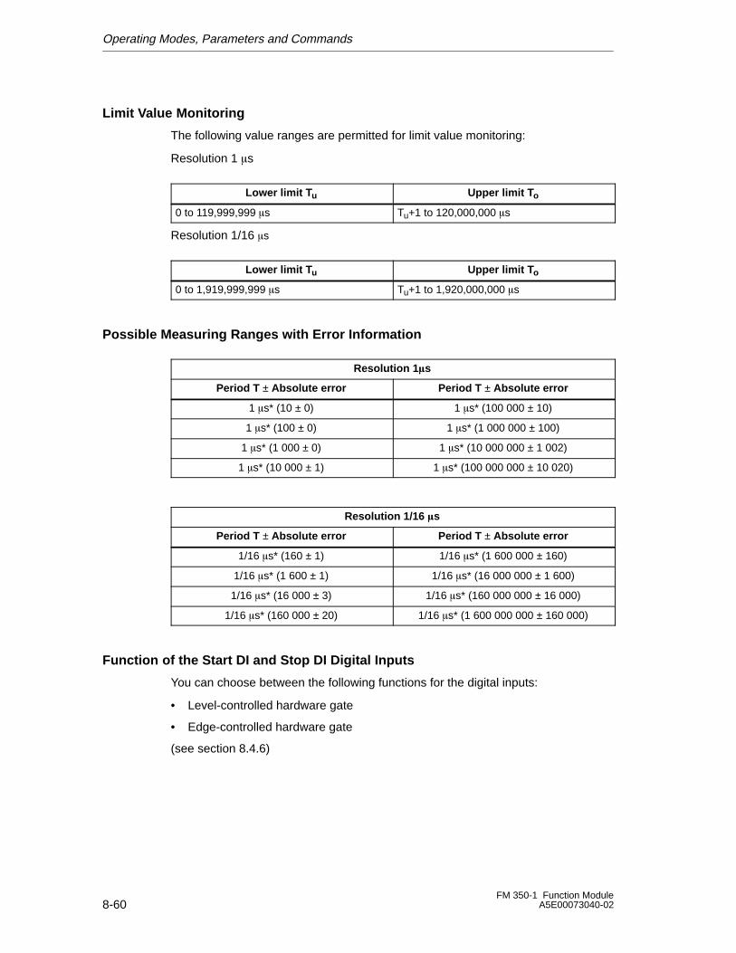
Operating Modes, Parameters and Commands
8-60FM 350-1 Function Module
A5E00073040-02
Limit Value Monitoring
The following value ranges are permitted for limit value monitoring:
Resolution 1 �s
Lower limit T u Upper limit T o
0 to 119,999,999 �s Tu+1 to 120,000,000 �s
Resolution 1/16 �s
Lower limit T u Upper limit T o
0 to 1,919,999,999 �s Tu+1 to 1,920,000,000 �s
Possible Measuring Ranges with Error Information
Resolution 1 �s
Period T ± Absolute error Period T ± Absolute error
1 �s* (10 ± 0) 1 �s* (100 000 ± 10)
1 �s* (100 ± 0) 1 �s* (1 000 000 ± 100)
1 �s* (1 000 ± 0) 1 �s* (10 000 000 ± 1 002)
1 �s* (10 000 ± 1) 1 �s* (100 000 000 ± 10 020)
Resolution 1/16 �s
Period T ± Absolute error Period T ± Absolute error
1/16 �s* (160 ± 1) 1/16 �s* (1 600 000 ± 160)
1/16 �s* (1 600 ± 1) 1/16 �s* (16 000 000 ± 1 600)
1/16 �s* (16 000 ± 3) 1/16 �s* (160 000 000 ± 16 000)
1/16 �s* (160 000 ± 20) 1/16 �s* (1 600 000 000 ± 160 000)
Function of the Start DI and Stop DI Digital Inputs
You can choose between the following functions for the digital inputs:
• Level-controlled hardware gate
• Edge-controlled hardware gate
(see section 8.4.6)
Operating Modes, Parameters and Commands
8-61FM 350-1 Function ModuleA5E00073040-02
Function of Digital Output DO0
You can choose between the following functions for digital output DO0:
• No comparison (no switching by limit value monitoring)
• Measured value outside limits
• Measured value under lower limit
• Measured value above upper limit
(see section 8.4.7)
Variable Values during Operation:
• Lower limit (L_PREPAR)
• Upper limit (T_CMP_V1)
• Update time (T_CMP_V2)
• Function of digital output DO0 (C_DOPARA)
(see section 8.4.7 and 5.6.2)
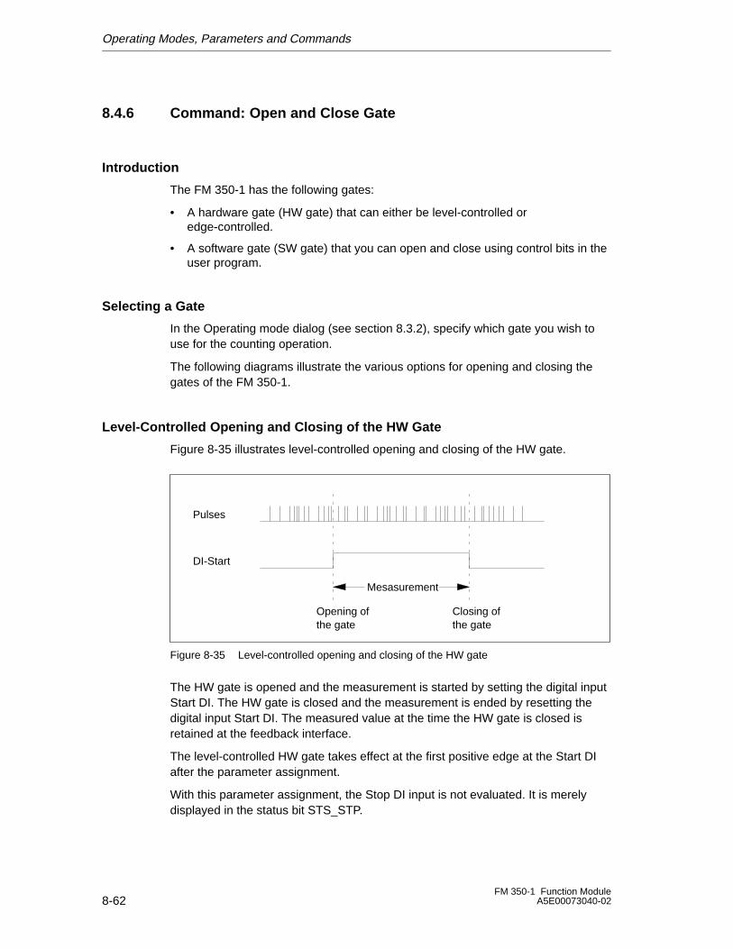
Operating Modes, Parameters and Commands
8-62FM 350-1 Function Module
A5E00073040-02
8.4.6 Command: Open and Close Gate
Introduction
The FM 350-1 has the following gates:
• A hardware gate (HW gate) that can either be level-controlled oredge-controlled.
• A software gate (SW gate) that you can open and close using control bits in theuser program.
Selecting a Gate
In the Operating mode dialog (see section 8.3.2), specify which gate you wish touse for the counting operation.
The following diagrams illustrate the various options for opening and closing thegates of the FM 350-1.
Level-Controlled Opening and Closing of the HW Gate
Figure 8-35 illustrates level-controlled opening and closing of the HW gate.
Opening ofthe gate
Closing ofthe gate
Pulses
DI-Start
Mesasurement
Figure 8-35 Level-controlled opening and closing of the HW gate
The HW gate is opened and the measurement is started by setting the digital inputStart DI. The HW gate is closed and the measurement is ended by resetting thedigital input Start DI. The measured value at the time the HW gate is closed isretained at the feedback interface.
The level-controlled HW gate takes effect at the first positive edge at the Start DIafter the parameter assignment.
With this parameter assignment, the Stop DI input is not evaluated. It is merelydisplayed in the status bit STS_STP.
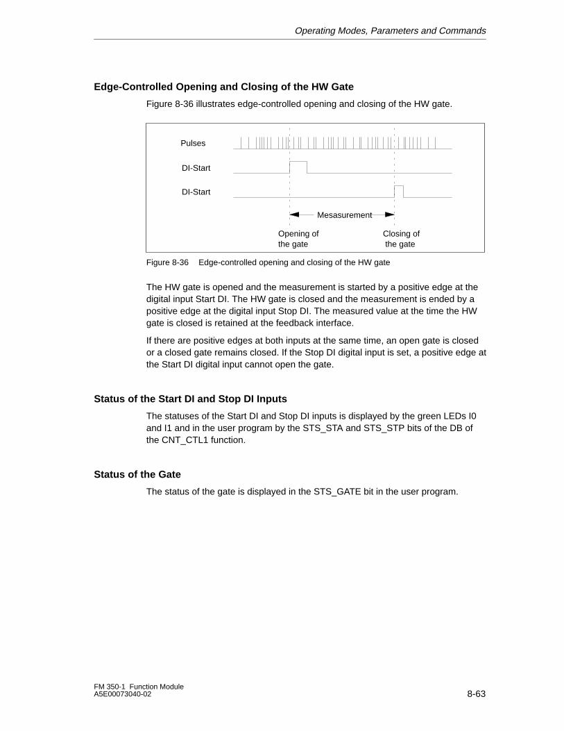
Operating Modes, Parameters and Commands
8-63FM 350-1 Function ModuleA5E00073040-02
Edge-Controlled Opening and Closing of the HW Gate
Figure 8-36 illustrates edge-controlled opening and closing of the HW gate.
DI-Start
DI-Start
Opening ofthe gate
Closing of the gate
Pulses
Mesasurement
Figure 8-36 Edge-controlled opening and closing of the HW gate
The HW gate is opened and the measurement is started by a positive edge at thedigital input Start DI. The HW gate is closed and the measurement is ended by apositive edge at the digital input Stop DI. The measured value at the time the HWgate is closed is retained at the feedback interface.
If there are positive edges at both inputs at the same time, an open gate is closedor a closed gate remains closed. If the Stop DI digital input is set, a positive edge atthe Start DI digital input cannot open the gate.
Status of the Start DI and Stop DI Inputs
The statuses of the Start DI and Stop DI inputs is displayed by the green LEDs I0and I1 and in the user program by the STS_STA and STS_STP bits of the DB ofthe CNT_CTL1 function.
Status of the Gate
The status of the gate is displayed in the STS_GATE bit in the user program.
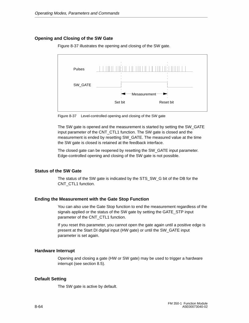
Operating Modes, Parameters and Commands
8-64FM 350-1 Function Module
A5E00073040-02
Opening and Closing of the SW Gate
Figure 8-37 illustrates the opening and closing of the SW gate.
Pulses
SW_GATE
Mesasurement
Set bit Reset bit
Figure 8-37 Level-controlled opening and closing of the SW gate
The SW gate is opened and the measurement is started by setting the SW_GATEinput parameter of the CNT_CTL1 function. The SW gate is closed and themeasurement is ended by resetting SW_GATE. The measured value at the timethe SW gate is closed is retained at the feedback interface.
The closed gate can be reopened by resetting the SW_GATE input parameter.Edge-controlled opening and closing of the SW gate is not possible.
Status of the SW Gate
The status of the SW gate is indicated by the STS_SW_G bit of the DB for theCNT_CTL1 function.
Ending the Measurement with the Gate Stop Function
You can also use the Gate Stop function to end the measurement regardless of thesignals applied or the status of the SW gate by setting the GATE_STP inputparameter of the CNT_CTL1 function.
If you reset this parameter, you cannot open the gate again until a positive edge ispresent at the Start DI digital input (HW gate) or until the SW_GATE inputparameter is set again.
Hardware Interrupt
Opening and closing a gate (HW or SW gate) may be used to trigger a hardwareinterrupt (see section 8.5).
Default Setting
The SW gate is active by default.
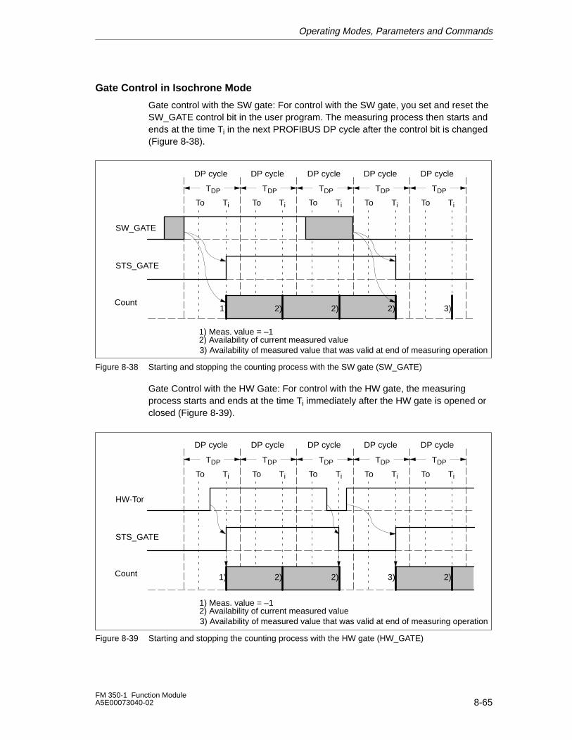
Operating Modes, Parameters and Commands
8-65FM 350-1 Function ModuleA5E00073040-02
Gate Control in Isochrone Mode
Gate control with the SW gate: For control with the SW gate, you set and reset theSW_GATE control bit in the user program. The measuring process then starts andends at the time Ti in the next PROFIBUS DP cycle after the control bit is changed(Figure 8-38).
STS_GATE
SW_GATE
Ti Ti
TDP TDPTDPTDPTDP
TiTi TiTo ToToTo To
2)2)2) 3)1)
DP cycle DP cycleDP cycleDP cycle DP cycle
Count
1) Meas. value = –12) Availability of current measured value3) Availability of measured value that was valid at end of measuring operation
Figure 8-38 Starting and stopping the counting process with the SW gate (SW_GATE)
Gate Control with the HW Gate: For control with the HW gate, the measuringprocess starts and ends at the time Ti immediately after the HW gate is opened orclosed (Figure 8-39).
STS_GATE
HW-Tor
Ti Ti
TDP TDPTDPTDPTDP
TiTi TiTo ToToTo To
2) 3) 2)2)1)
DP cycle DP cycleDP cycleDP cycle DP cycle
Count
1) Meas. value = –12) Availability of current measured value3) Availability of measured value that was valid at end of measuring operation
Figure 8-39 Starting and stopping the counting process with the HW gate (HW_GATE)
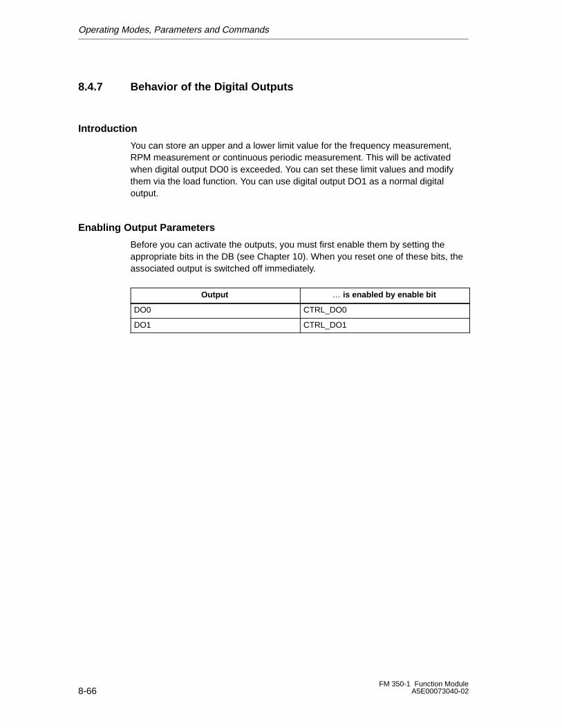
Operating Modes, Parameters and Commands
8-66FM 350-1 Function Module
A5E00073040-02
8.4.7 Behavior of the Digital Outputs
Introduction
You can store an upper and a lower limit value for the frequency measurement,RPM measurement or continuous periodic measurement. This will be activatedwhen digital output DO0 is exceeded. You can set these limit values and modifythem via the load function. You can use digital output DO1 as a normal digitaloutput.
Enabling Output Parameters
Before you can activate the outputs, you must first enable them by setting theappropriate bits in the DB (see Chapter 10). When you reset one of these bits, theassociated output is switched off immediately.
Output … is enabled by enable bit
DO0 CTRL_DO0
DO1 CTRL_DO1
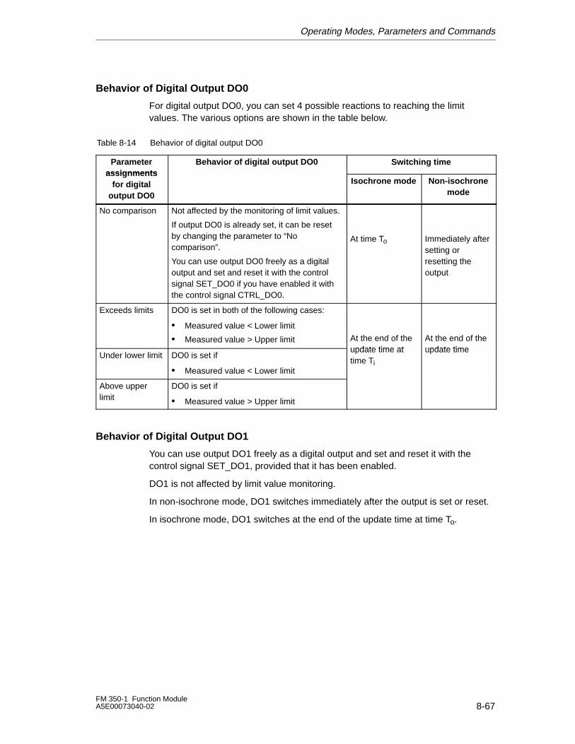
Operating Modes, Parameters and Commands
8-67FM 350-1 Function ModuleA5E00073040-02
Behavior of Digital Output DO0
For digital output DO0, you can set 4 possible reactions to reaching the limitvalues. The various options are shown in the table below.
Table 8-14 Behavior of digital output DO0
Parameterassignments
Behavior of digital output DO0 Switching timeass ignmen ts
for digitaloutput DO0
Isochrone mode Non-isochronemode
No comparison Not affected by the monitoring of limit values.
If output DO0 is already set, it can be resetby changing the parameter to “Nocomparison”.
You can use output DO0 freely as a digitaloutput and set and reset it with the controlsignal SET_DO0 if you have enabled it withthe control signal CTRL_DO0.
At time To Immediately aftersetting orresetting theoutput
Exceeds limits DO0 is set in both of the following cases:
• Measured value < Lower limit
• Measured value > Upper limit At the end of theupdate time at
At the end of theupdate time
Under lower limit DO0 is set if
• Measured value < Lower limit
update time attime Ti
update time
Above upperlimit
DO0 is set if
• Measured value > Upper limit
Behavior of Digital Output DO1
You can use output DO1 freely as a digital output and set and reset it with thecontrol signal SET_DO1, provided that it has been enabled.
DO1 is not affected by limit value monitoring.
In non-isochrone mode, DO1 switches immediately after the output is set or reset.
In isochrone mode, DO1 switches at the end of the update time at time To.
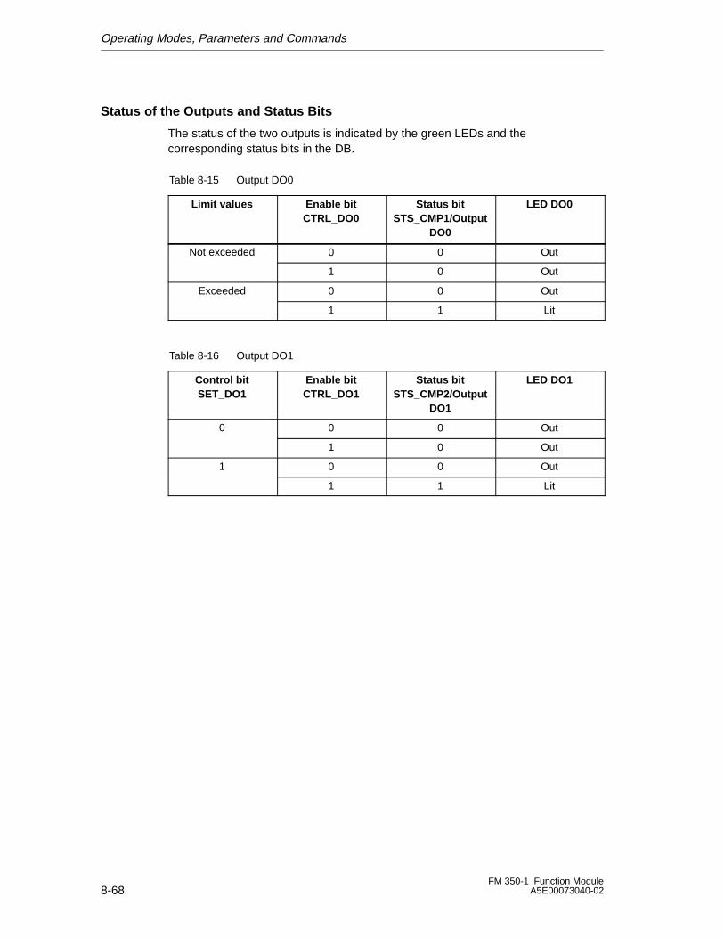
Operating Modes, Parameters and Commands
8-68FM 350-1 Function Module
A5E00073040-02
Status of the Outputs and Status Bits
The status of the two outputs is indicated by the green LEDs and thecorresponding status bits in the DB.
Table 8-15 Output DO0
Limit values Enable bitCTRL_DO0
Status bitSTS_CMP1/Output
DO0
LED DO0
Not exceeded 0 0 Out
1 0 Out
Exceeded 0 0 Out
1 1 Lit
Table 8-16 Output DO1
Control bitSET_DO1
Enable bitCTRL_DO1
Status bitSTS_CMP2/Output
DO1
LED DO1
0 0 0 Out
1 0 Out
1 0 0 Out
1 1 Lit
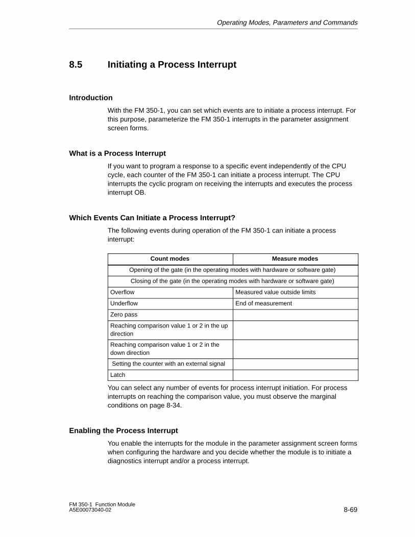
Operating Modes, Parameters and Commands
8-69FM 350-1 Function ModuleA5E00073040-02
8.5 Initiating a Process Interrupt
Introduction
With the FM 350-1, you can set which events are to initiate a process interrupt. Forthis purpose, parameterize the FM 350-1 interrupts in the parameter assignmentscreen forms.
What is a Process Interrupt
If you want to program a response to a specific event independently of the CPUcycle, each counter of the FM 350-1 can initiate a process interrupt. The CPUinterrupts the cyclic program on receiving the interrupts and executes the processinterrupt OB.
Which Events Can Initiate a Process Interrupt?
The following events during operation of the FM 350-1 can initiate a processinterrupt:
Count modes Measure modes
Opening of the gate (in the operating modes with hardware or software gate)
Closing of the gate (in the operating modes with hardware or software gate)
Overflow Measured value outside limits
Underflow End of measurement
Zero pass
Reaching comparison value 1 or 2 in the updirection
Reaching comparison value 1 or 2 in thedown direction
Setting the counter with an external signal
Latch
You can select any number of events for process interrupt initiation. For processinterrupts on reaching the comparison value, you must observe the marginalconditions on page 8-34.
Enabling the Process Interrupt
You enable the interrupts for the module in the parameter assignment screen formswhen configuring the hardware and you decide whether the module is to initiate adiagnostics interrupt and/or a process interrupt.
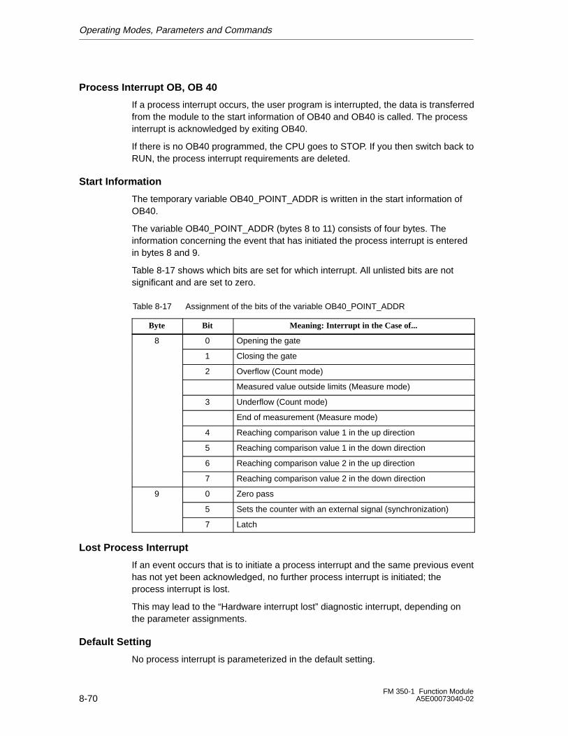
Operating Modes, Parameters and Commands
8-70FM 350-1 Function Module
A5E00073040-02
Process Interrupt OB, OB 40
If a process interrupt occurs, the user program is interrupted, the data is transferredfrom the module to the start information of OB40 and OB40 is called. The processinterrupt is acknowledged by exiting OB40.
If there is no OB40 programmed, the CPU goes to STOP. If you then switch back toRUN, the process interrupt requirements are deleted.
Start Information
The temporary variable OB40_POINT_ADDR is written in the start information ofOB40.
The variable OB40_POINT_ADDR (bytes 8 to 11) consists of four bytes. Theinformation concerning the event that has initiated the process interrupt is enteredin bytes 8 and 9.
Table 8-17 shows which bits are set for which interrupt. All unlisted bits are notsignificant and are set to zero.
Table 8-17 Assignment of the bits of the variable OB40_POINT_ADDR
Byte Bit Meaning: Interrupt in the Case of...
8 0 Opening the gate
1 Closing the gate
2 Overflow (Count mode)
Measured value outside limits (Measure mode)
3 Underflow (Count mode)
End of measurement (Measure mode)
4 Reaching comparison value 1 in the up direction
5 Reaching comparison value 1 in the down direction
6 Reaching comparison value 2 in the up direction
7 Reaching comparison value 2 in the down direction
9 0 Zero pass
5 Sets the counter with an external signal (synchronization)
7 Latch
Lost Process Interrupt
If an event occurs that is to initiate a process interrupt and the same previous eventhas not yet been acknowledged, no further process interrupt is initiated; theprocess interrupt is lost.
This may lead to the “Hardware interrupt lost” diagnostic interrupt, depending onthe parameter assignments.
Default Setting
No process interrupt is parameterized in the default setting.
Encoder Signals and Their Evaluation
9-1FM 350-1 Function ModuleA5E00073040-02
Encoder Signals and Their Evaluation
This Chapter...
This chapter describes the following:
• The encoders you can connect to the counters of the FM 350-1.
• The time sequence of the signals of the different encoders.
• How the FM 350-1 can perform multiple evaluations of the encoder signals.
• How the module monitors the different encoder signals.
• The signals for which you can parameterize input filters.
Chapter Overview
Section Description Page
9.1 Overview 9-2
9.2 5 V Differential Signals 9-3
9.3 24 V Signals 9-5
9.4 Pulse Evaluation 9-7
9
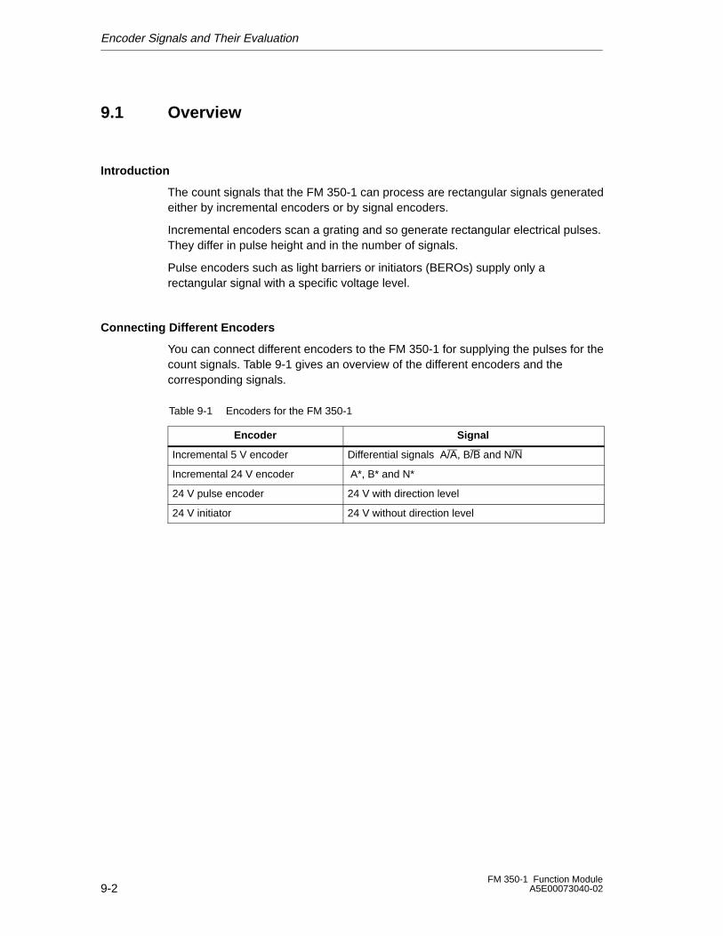
Encoder Signals and Their Evaluation
9-2FM 350-1 Function Module
A5E00073040-02
9.1 Overview
Introduction
The count signals that the FM 350-1 can process are rectangular signals generatedeither by incremental encoders or by signal encoders.
Incremental encoders scan a grating and so generate rectangular electrical pulses.They differ in pulse height and in the number of signals.
Pulse encoders such as light barriers or initiators (BEROs) supply only arectangular signal with a specific voltage level.
Connecting Different Encoders
You can connect different encoders to the FM 350-1 for supplying the pulses for thecount signals. Table 9-1 gives an overview of the different encoders and thecorresponding signals.
Table 9-1 Encoders for the FM 350-1
Encoder Signal
Incremental 5 V encoder Differential signals A/A, B/B and N/N
Incremental 24 V encoder A*, B* and N*
24 V pulse encoder 24 V with direction level
24 V initiator 24 V without direction level
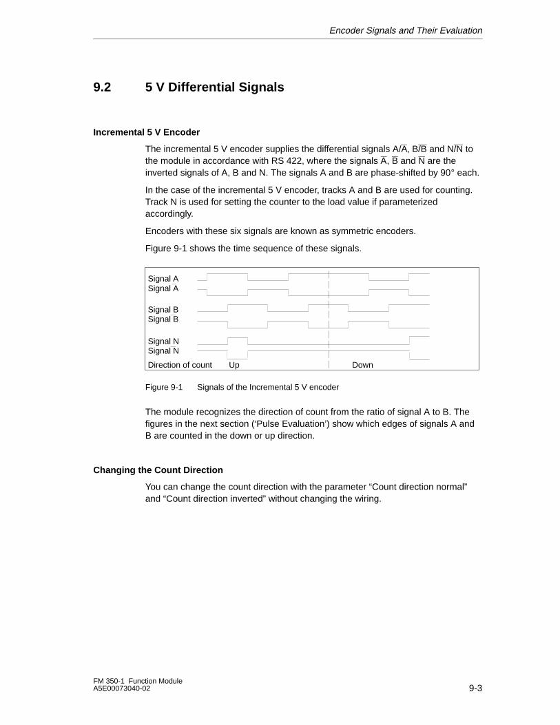
Encoder Signals and Their Evaluation
9-3FM 350-1 Function ModuleA5E00073040-02
9.2 5 V Differential Signals
Incremental 5 V Encoder
The incremental 5 V encoder supplies the differential signals A/A, B/B and N/N tothe module in accordance with RS 422, where the signals A, B and N are theinverted signals of A, B and N. The signals A and B are phase-shifted by 90° each.
In the case of the incremental 5 V encoder, tracks A and B are used for counting.Track N is used for setting the counter to the load value if parameterizedaccordingly.
Encoders with these six signals are known as symmetric encoders.
Figure 9-1 shows the time sequence of these signals.
Signal A
Signal B
Direction of count Up Down
Signal A
Signal B
Signal NSignal N
Figure 9-1 Signals of the Incremental 5 V encoder
The module recognizes the direction of count from the ratio of signal A to B. Thefigures in the next section (‘Pulse Evaluation’) show which edges of signals A andB are counted in the down or up direction.
Changing the Count Direction
You can change the count direction with the parameter “Count direction normal”and “Count direction inverted” without changing the wiring.
Encoder Signals and Their Evaluation
9-4FM 350-1 Function Module
A5E00073040-02
How are the Signals Monitored?
The module monitors for cable connection and for wirebreak or short-circuit.
Via parameterization, you can determine which of the three signal pairs aremonitored. You therefore need not wire unused signals if diagnostics for this signalpair has been switched off via parameterization (set counter with zero mark).
If all three signals report errors, either the encoder is defective, there is ashort-circuit in the “5.2 VDC” encoder supply or there is no encoder connected.
If the module detects an error after you have assigned your parameters, an entry ismade in the diagnostics data sets DS0 and DS1. This can result in a diagnosticsinterrupt if the relevant parameters have been assigned.
Coding Connector
For this encoder, you must set the coding connector to position A.
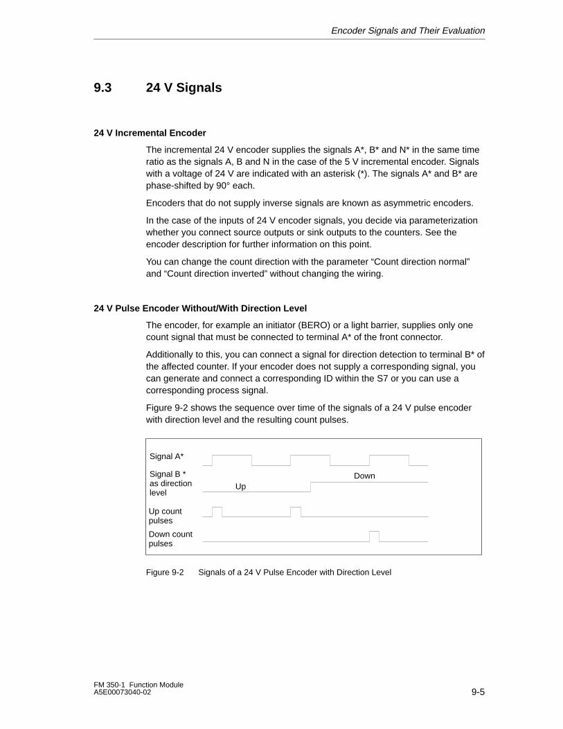
Encoder Signals and Their Evaluation
9-5FM 350-1 Function ModuleA5E00073040-02
9.3 24 V Signals
24 V Incremental Encoder
The incremental 24 V encoder supplies the signals A*, B* and N* in the same timeratio as the signals A, B and N in the case of the 5 V incremental encoder. Signalswith a voltage of 24 V are indicated with an asterisk (*). The signals A* and B* arephase-shifted by 90° each.
Encoders that do not supply inverse signals are known as asymmetric encoders.
In the case of the inputs of 24 V encoder signals, you decide via parameterizationwhether you connect source outputs or sink outputs to the counters. See theencoder description for further information on this point.
You can change the count direction with the parameter “Count direction normal”and “Count direction inverted” without changing the wiring.
24 V Pulse Encoder Without/With Direction Level
The encoder, for example an initiator (BERO) or a light barrier, supplies only onecount signal that must be connected to terminal A* of the front connector.
Additionally to this, you can connect a signal for direction detection to terminal B* ofthe affected counter. If your encoder does not supply a corresponding signal, youcan generate and connect a corresponding ID within the S7 or you can use acorresponding process signal.
Figure 9-2 shows the sequence over time of the signals of a 24 V pulse encoderwith direction level and the resulting count pulses.
Signal A*
Signal B *as directionlevel
Up countpulses
Down countpulses
UpDown
Figure 9-2 Signals of a 24 V Pulse Encoder with Direction Level
Encoder Signals and Their Evaluation
9-6FM 350-1 Function Module
A5E00073040-02
Parameterization of the Encoder Inputs
The count direction is defined via the parameterization of the encoder inputs. Table9-2 shows the count direction changes in dependence on the parameterization.
Table 9-2 Count Direction in Dependence on the Input Parameterization
Input Parameterization Terminal B* Count Direction
Current sourcing Unswitched Up
24 V connected Down
Current sinking Unswitched Down
Short-circuited to ground Up
For parameterization, select “24 V pulse and direction” for the encoder selection.
Changing direction by inverting the B* signal is not possible with these countsignals.
Note
With this type of evaluation, the count value in the case of an oscillating countsignal can ‘run away’ at the edge since all the signals are added together.
Input Filters for 24 V Count Inputs
To suppress interference, you can parameterize input filters with a uniform filtertime for the 24 V inputs A*, B* and N* and for the digital inputs. The following inputfilters are available:
Table 9-3 Input Filters
Features Input Filter 1(Default)
Input Filter 2
Typical input delay 1 �s 15 �s
Maximum count frequency 200 kHz 20 kHz
Minimum pulse width of the count signals 2.5 �s 25 �s
How are the Signals Monitored?
24 V count signals are not monitored for wirebreak or short-circuit.
Coding Connector
For this encoder, you must set the coding connector to position B.
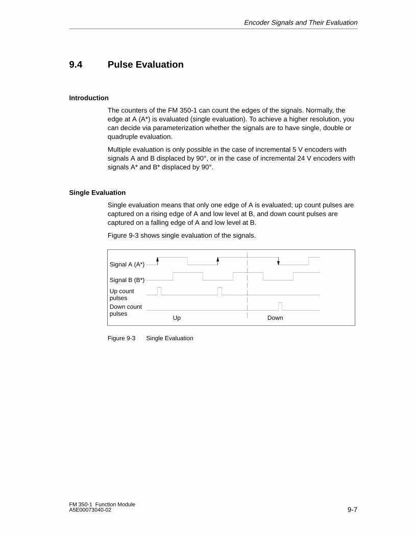
Encoder Signals and Their Evaluation
9-7FM 350-1 Function ModuleA5E00073040-02
9.4 Pulse Evaluation
Introduction
The counters of the FM 350-1 can count the edges of the signals. Normally, theedge at A (A*) is evaluated (single evaluation). To achieve a higher resolution, youcan decide via parameterization whether the signals are to have single, double orquadruple evaluation.
Multiple evaluation is only possible in the case of incremental 5 V encoders withsignals A and B displaced by 90°, or in the case of incremental 24 V encoders withsignals A* and B* displaced by 90°.
Single Evaluation
Single evaluation means that only one edge of A is evaluated; up count pulses arecaptured on a rising edge of A and low level at B, and down count pulses arecaptured on a falling edge of A and low level at B.
Figure 9-3 shows single evaluation of the signals.
Signal A (A*)
Signal B (B*)
Up countpulsesDown countpulses
Up Down
Figure 9-3 Single Evaluation
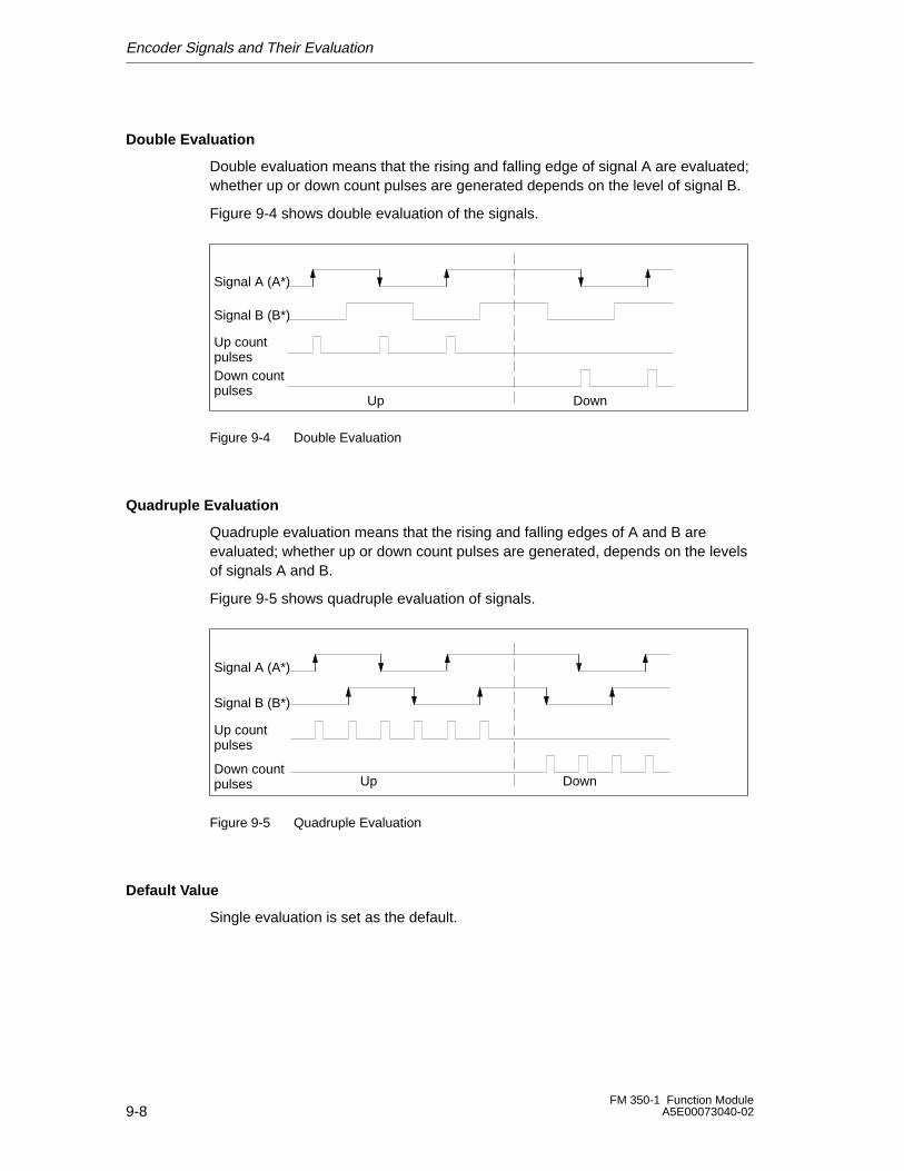
Encoder Signals and Their Evaluation
9-8FM 350-1 Function Module
A5E00073040-02
Double Evaluation
Double evaluation means that the rising and falling edge of signal A are evaluated;whether up or down count pulses are generated depends on the level of signal B.
Figure 9-4 shows double evaluation of the signals.
Signal A (A*)
Signal B (B*)
Up countpulsesDown countpulses
Up Down
Figure 9-4 Double Evaluation
Quadruple Evaluation
Quadruple evaluation means that the rising and falling edges of A and B areevaluated; whether up or down count pulses are generated, depends on the levelsof signals A and B.
Figure 9-5 shows quadruple evaluation of signals.
Signal A (A*)
Signal B (B*)
Up countpulses
Down countpulses Up Down
Figure 9-5 Quadruple Evaluation
Default Value
Single evaluation is set as the default.
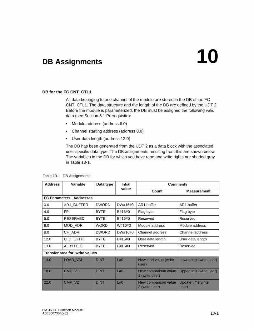
10-1FM 350-1 Function ModuleA5E00073040-02
DB Assignments
DB for the FC CNT_CTL1
All data belonging to one channel of the module are stored in the DB of the FCCNT_CTL1. The data structure and the length of the DB are defined by the UDT 2.Before the module is parameterized, the DB must be assigned the following validdata (see Section 5.1 Prerequisite):
• Module address (address 6.0)
• Channel starting address (address 8.0)
• User data length (address 12.0)
The DB has been generated from the UDT 2 as a data block with the associateduser-specific data type. The DB assignments resulting from this are shown below.The variables in the DB for which you have read and write rights are shaded grayin Table 10-1.
Table 10-1 DB Assignments
Address Variable Data type Intialal e
Commentsvalue
Count Measurement
FC Parameters, Addresses
0.0 AR1_BUFFER DWORD DW#16#0 AR1 buffer AR1 buffer
4.0 FP BYTE B#16#0 Flag byte Flag byte
5.0 RESERVED BYTE B#16#0 Reserved Reserved
6.0 MOD_ADR WORD W#16#0 Module address Module address
8.0 CH_ADR DWORD DW#16#0 Channel address Channel address
12.0 U_D_LGTH BYTE B#16#0 User data length User data length
13.0 A_BYTE_0 BYTE B#16#0 Reserved Reserved
Transfer area for write values
14.0 LOAD_VAL DINT L#0 New load value (writeuser)
Lower limit (write user)
18.0 CMP_V1 DINT L#0 New comparison value1 (write user)
Upper limit (write user)
22.0 CMP_V2 DINT L#0 New comparison value2 (write user)
Update time(writeuser)
10
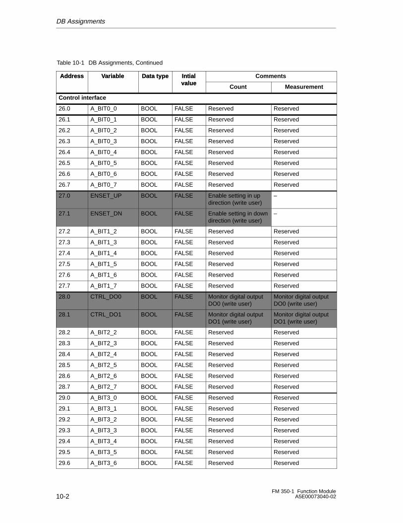
DB Assignments
10-2FM 350-1 Function Module
A5E00073040-02
Table 10-1 DB Assignments, Continued
Address CommentsIntialvalue
Data typeVariable
Measurement
Address
Count
Intialvalue
Data typeVariable
Control interface
26.0 A_BIT0_0 BOOL FALSE Reserved Reserved
26.1 A_BIT0_1 BOOL FALSE Reserved Reserved
26.2 A_BIT0_2 BOOL FALSE Reserved Reserved
26.3 A_BIT0_3 BOOL FALSE Reserved Reserved
26.4 A_BIT0_4 BOOL FALSE Reserved Reserved
26.5 A_BIT0_5 BOOL FALSE Reserved Reserved
26.6 A_BIT0_6 BOOL FALSE Reserved Reserved
26.7 A_BIT0_7 BOOL FALSE Reserved Reserved
27.0 ENSET_UP BOOL FALSE Enable setting in updirection (write user)
–
27.1 ENSET_DN BOOL FALSE Enable setting in downdirection (write user)
–
27.2 A_BIT1_2 BOOL FALSE Reserved Reserved
27.3 A_BIT1_3 BOOL FALSE Reserved Reserved
27.4 A_BIT1_4 BOOL FALSE Reserved Reserved
27.5 A_BIT1_5 BOOL FALSE Reserved Reserved
27.6 A_BIT1_6 BOOL FALSE Reserved Reserved
27.7 A_BIT1_7 BOOL FALSE Reserved Reserved
28.0 CTRL_DO0 BOOL FALSE Monitor digital outputDO0 (write user)
Monitor digital outputDO0 (write user)
28.1 CTRL_DO1 BOOL FALSE Monitor digital outputDO1 (write user)
Monitor digital outputDO1 (write user)
28.2 A_BIT2_2 BOOL FALSE Reserved Reserved
28.3 A_BIT2_3 BOOL FALSE Reserved Reserved
28.4 A_BIT2_4 BOOL FALSE Reserved Reserved
28.5 A_BIT2_5 BOOL FALSE Reserved Reserved
28.6 A_BIT2_6 BOOL FALSE Reserved Reserved
28.7 A_BIT2_7 BOOL FALSE Reserved Reserved
29.0 A_BIT3_0 BOOL FALSE Reserved Reserved
29.1 A_BIT3_1 BOOL FALSE Reserved Reserved
29.2 A_BIT3_2 BOOL FALSE Reserved Reserved
29.3 A_BIT3_3 BOOL FALSE Reserved Reserved
29.4 A_BIT3_4 BOOL FALSE Reserved Reserved
29.5 A_BIT3_5 BOOL FALSE Reserved Reserved
29.6 A_BIT3_6 BOOL FALSE Reserved Reserved
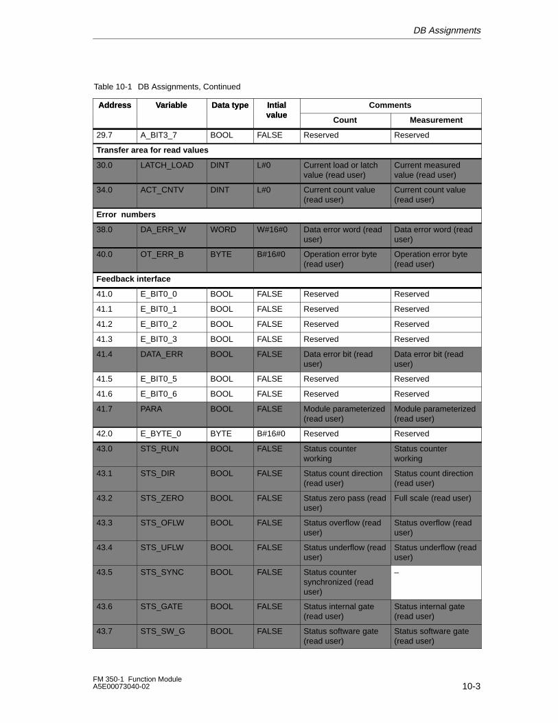
DB Assignments
10-3FM 350-1 Function ModuleA5E00073040-02
Table 10-1 DB Assignments, Continued
Address CommentsIntialvalue
Data typeVariable
Measurement
Address
Count
Intialvalue
Data typeVariable
29.7 A_BIT3_7 BOOL FALSE Reserved Reserved
Transfer area for read values
30.0 LATCH_LOAD DINT L#0 Current load or latchvalue (read user)
Current measuredvalue (read user)
34.0 ACT_CNTV DINT L#0 Current count value(read user)
Current count value(read user)
Error numbers
38.0 DA_ERR_W WORD W#16#0 Data error word (readuser)
Data error word (readuser)
40.0 OT_ERR_B BYTE B#16#0 Operation error byte(read user)
Operation error byte(read user)
Feedback interface
41.0 E_BIT0_0 BOOL FALSE Reserved Reserved
41.1 E_BIT0_1 BOOL FALSE Reserved Reserved
41.2 E_BIT0_2 BOOL FALSE Reserved Reserved
41.3 E_BIT0_3 BOOL FALSE Reserved Reserved
41.4 DATA_ERR BOOL FALSE Data error bit (readuser)
Data error bit (readuser)
41.5 E_BIT0_5 BOOL FALSE Reserved Reserved
41.6 E_BIT0_6 BOOL FALSE Reserved Reserved
41.7 PARA BOOL FALSE Module parameterized(read user)
Module parameterized(read user)
42.0 E_BYTE_0 BYTE B#16#0 Reserved Reserved
43.0 STS_RUN BOOL FALSE Status counterworking
Status counterworking
43.1 STS_DIR BOOL FALSE Status count direction(read user)
Status count direction(read user)
43.2 STS_ZERO BOOL FALSE Status zero pass (readuser)
Full scale (read user)
43.3 STS_OFLW BOOL FALSE Status overflow (readuser)
Status overflow (readuser)
43.4 STS_UFLW BOOL FALSE Status underflow (readuser)
Status underflow (readuser)
43.5 STS_SYNC BOOL FALSE Status countersynchronized (readuser)
–
43.6 STS_GATE BOOL FALSE Status internal gate(read user)
Status internal gate(read user)
43.7 STS_SW_G BOOL FALSE Status software gate(read user)
Status software gate(read user)
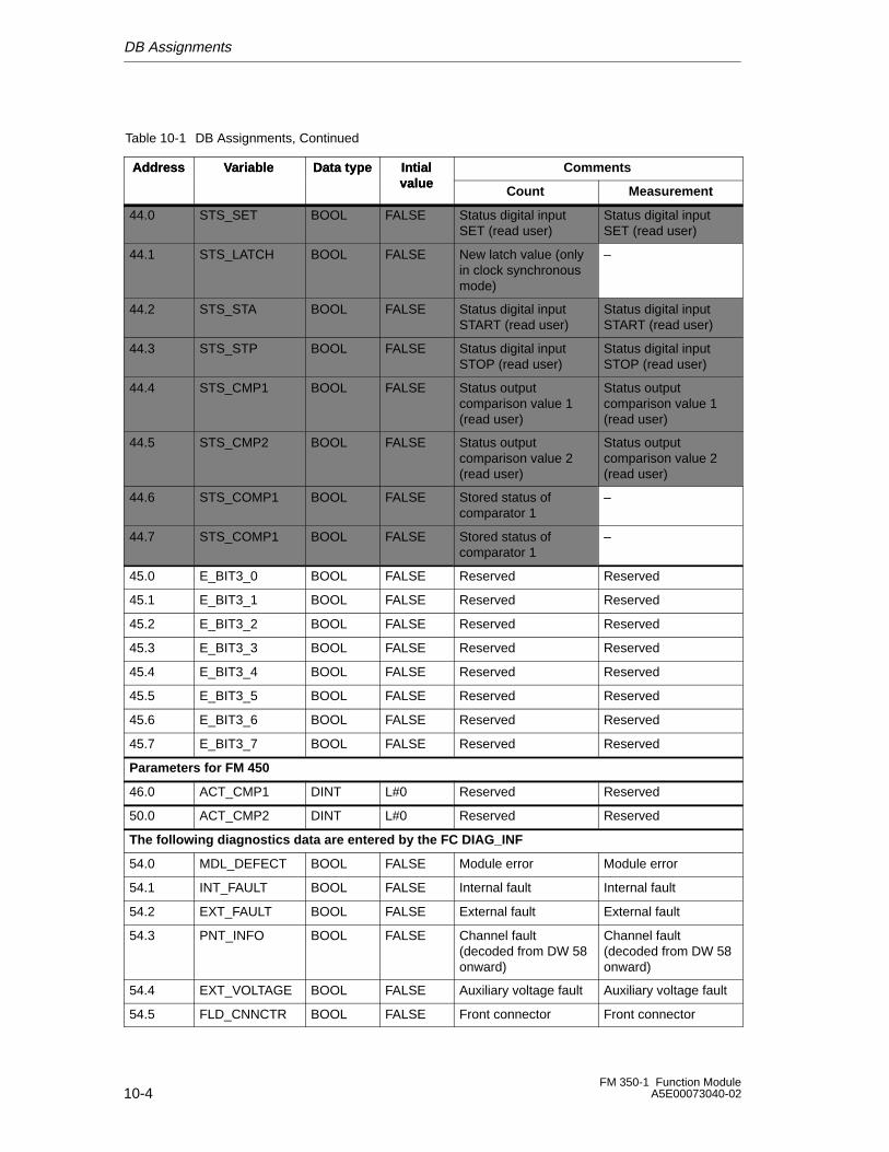
DB Assignments
10-4FM 350-1 Function Module
A5E00073040-02
Table 10-1 DB Assignments, Continued
Address CommentsIntialvalue
Data typeVariable
Measurement
Address
Count
Intialvalue
Data typeVariable
44.0 STS_SET BOOL FALSE Status digital inputSET (read user)
Status digital inputSET (read user)
44.1 STS_LATCH BOOL FALSE New latch value (onlyin clock synchronousmode)
–
44.2 STS_STA BOOL FALSE Status digital inputSTART (read user)
Status digital inputSTART (read user)
44.3 STS_STP BOOL FALSE Status digital inputSTOP (read user)
Status digital inputSTOP (read user)
44.4 STS_CMP1 BOOL FALSE Status outputcomparison value 1(read user)
Status outputcomparison value 1(read user)
44.5 STS_CMP2 BOOL FALSE Status outputcomparison value 2(read user)
Status outputcomparison value 2(read user)
44.6 STS_COMP1 BOOL FALSE Stored status ofcomparator 1
–
44.7 STS_COMP1 BOOL FALSE Stored status ofcomparator 1
–
45.0 E_BIT3_0 BOOL FALSE Reserved Reserved
45.1 E_BIT3_1 BOOL FALSE Reserved Reserved
45.2 E_BIT3_2 BOOL FALSE Reserved Reserved
45.3 E_BIT3_3 BOOL FALSE Reserved Reserved
45.4 E_BIT3_4 BOOL FALSE Reserved Reserved
45.5 E_BIT3_5 BOOL FALSE Reserved Reserved
45.6 E_BIT3_6 BOOL FALSE Reserved Reserved
45.7 E_BIT3_7 BOOL FALSE Reserved Reserved
Parameters for FM 450
46.0 ACT_CMP1 DINT L#0 Reserved Reserved
50.0 ACT_CMP2 DINT L#0 Reserved Reserved
The following diagnostics data are entered by the FC DIAG_INF
54.0 MDL_DEFECT BOOL FALSE Module error Module error
54.1 INT_FAULT BOOL FALSE Internal fault Internal fault
54.2 EXT_FAULT BOOL FALSE External fault External fault
54.3 PNT_INFO BOOL FALSE Channel fault(decoded from DW 58onward)
Channel fault(decoded from DW 58onward)
54.4 EXT_VOLTAGE BOOL FALSE Auxiliary voltage fault Auxiliary voltage fault
54.5 FLD_CNNCTR BOOL FALSE Front connector Front connector
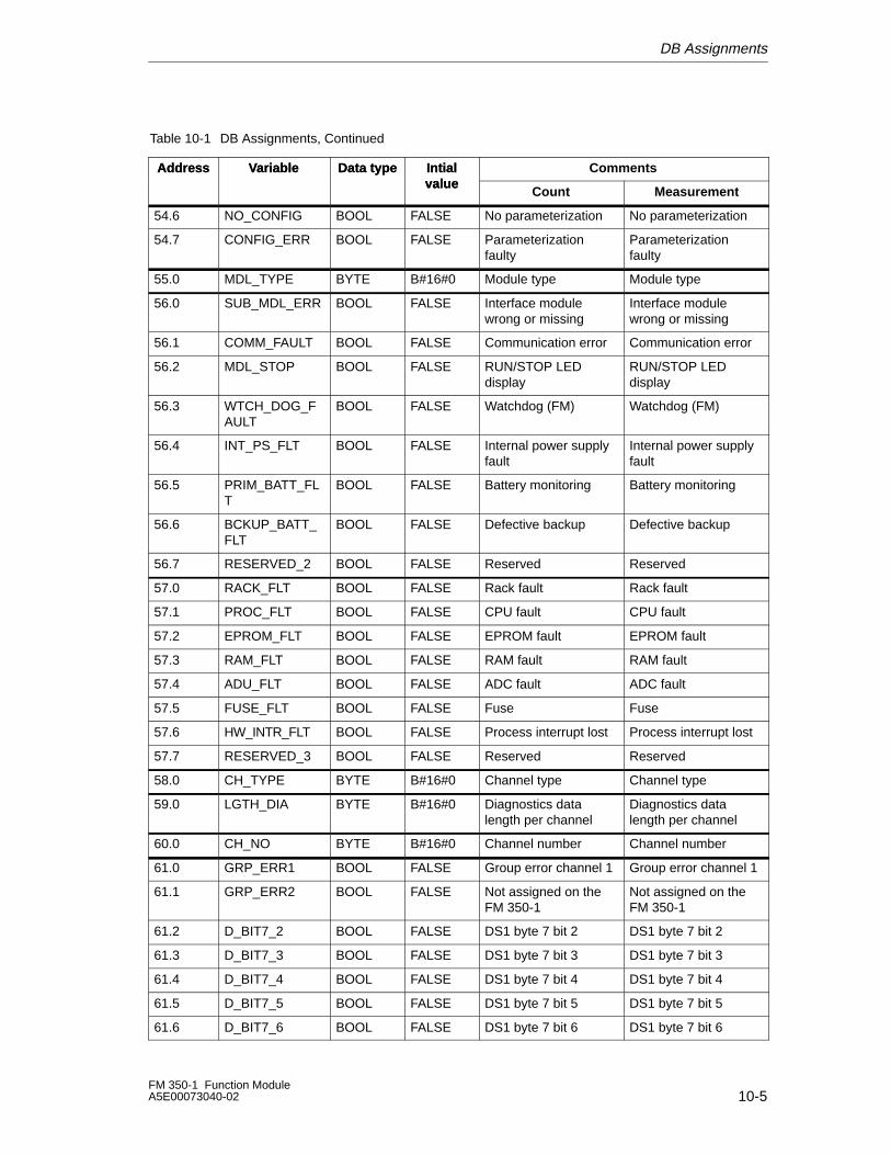
DB Assignments
10-5FM 350-1 Function ModuleA5E00073040-02
Table 10-1 DB Assignments, Continued
Address CommentsIntialvalue
Data typeVariable
Measurement
Address
Count
Intialvalue
Data typeVariable
54.6 NO_CONFIG BOOL FALSE No parameterization No parameterization
54.7 CONFIG_ERR BOOL FALSE Parameterizationfaulty
Parameterizationfaulty
55.0 MDL_TYPE BYTE B#16#0 Module type Module type
56.0 SUB_MDL_ERR BOOL FALSE Interface modulewrong or missing
Interface modulewrong or missing
56.1 COMM_FAULT BOOL FALSE Communication error Communication error
56.2 MDL_STOP BOOL FALSE RUN/STOP LEDdisplay
RUN/STOP LEDdisplay
56.3 WTCH_DOG_FAULT
BOOL FALSE Watchdog (FM) Watchdog (FM)
56.4 INT_PS_FLT BOOL FALSE Internal power supplyfault
Internal power supplyfault
56.5 PRIM_BATT_FLT
BOOL FALSE Battery monitoring Battery monitoring
56.6 BCKUP_BATT_FLT
BOOL FALSE Defective backup Defective backup
56.7 RESERVED_2 BOOL FALSE Reserved Reserved
57.0 RACK_FLT BOOL FALSE Rack fault Rack fault
57.1 PROC_FLT BOOL FALSE CPU fault CPU fault
57.2 EPROM_FLT BOOL FALSE EPROM fault EPROM fault
57.3 RAM_FLT BOOL FALSE RAM fault RAM fault
57.4 ADU_FLT BOOL FALSE ADC fault ADC fault
57.5 FUSE_FLT BOOL FALSE Fuse Fuse
57.6 HW_INTR_FLT BOOL FALSE Process interrupt lost Process interrupt lost
57.7 RESERVED_3 BOOL FALSE Reserved Reserved
58.0 CH_TYPE BYTE B#16#0 Channel type Channel type
59.0 LGTH_DIA BYTE B#16#0 Diagnostics datalength per channel
Diagnostics datalength per channel
60.0 CH_NO BYTE B#16#0 Channel number Channel number
61.0 GRP_ERR1 BOOL FALSE Group error channel 1 Group error channel 1
61.1 GRP_ERR2 BOOL FALSE Not assigned on theFM 350-1
Not assigned on theFM 350-1
61.2 D_BIT7_2 BOOL FALSE DS1 byte 7 bit 2 DS1 byte 7 bit 2
61.3 D_BIT7_3 BOOL FALSE DS1 byte 7 bit 3 DS1 byte 7 bit 3
61.4 D_BIT7_4 BOOL FALSE DS1 byte 7 bit 4 DS1 byte 7 bit 4
61.5 D_BIT7_5 BOOL FALSE DS1 byte 7 bit 5 DS1 byte 7 bit 5
61.6 D_BIT7_6 BOOL FALSE DS1 byte 7 bit 6 DS1 byte 7 bit 6
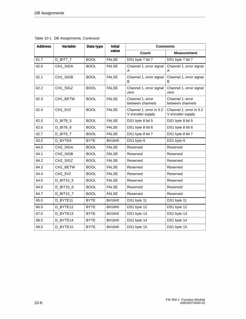
DB Assignments
10-6FM 350-1 Function Module
A5E00073040-02
Table 10-1 DB Assignments, Continued
Address CommentsIntialvalue
Data typeVariable
Measurement
Address
Count
Intialvalue
Data typeVariable
61.7 D_BIT7_7 BOOL FALSE DS1 byte 7 bit 7 DS1 byte 7 bit 7
62.0 CH1_SIGA BOOL FALSE Channel 1, error signalA
Channel 1, error signalA
62.1 CH1_SIGB BOOL FALSE Channel 1, error signalB
Channel 1, error signalB
62.2 CH1_SIGZ BOOL FALSE Channel 1, error signalzero
Channel 1, error signalzero
62.3 CH1_BETW BOOL FALSE Channel 1, errorbetween channels
Channel 1, errorbetween channels
62.4 CH1_5V2 BOOL FALSE Channel 1, error in 5.2V encoder supply
Channel 1, error in 5.2V encoder supply
62.5 D_BIT8_5 BOOL FALSE DS1 byte 8 bit 5 DS1 byte 8 bit 5
62.6 D_BIT8_6 BOOL FALSE DS1 byte 8 bit 6 DS1 byte 8 bit 6
62.7 D_BIT8_7 BOOL FALSE DS1 byte 8 bit 7 DS1 byte 8 bit 7
63.0 D_BYTE9 BYTE B#16#0 DS1 byte 9 DS1 byte 9
64.0 CH2_SIGA BOOL FALSE Reserved Reserved
64.1 CH2_SIGB BOOL FALSE Reserved Reserved
64.2 CH2_SIGZ BOOL FALSE Reserved Reserved
64.3 CH2_BETW BOOL FALSE Reserved Reserved
64.4 CH2_5V2 BOOL FALSE Reserved Reserved
64.5 D_BIT10_5 BOOL FALSE Reserved Reserved
64.6 D_BIT10_6 BOOL FALSE Reserved Reserved
64.7 D_BIT10_7 BOOL FALSE Reserved Reserved
65.0 D_BYTE11 BYTE B#16#0 DS1 byte 11 DS1 byte 11
66.0 D_BYTE12 BYTE B#16#0 DS1 byte 12 DS1 byte 12
67.0 D_BYTE13 BYTE B#16#0 DS1 byte 13 DS1 byte 13
68.0 D_BYTE14 BYTE B#16#0 DS1 byte 14 DS1 byte 14
69.0 D_BYTE15 BYTE B#16#0 DS1 byte 15 DS1 byte 15
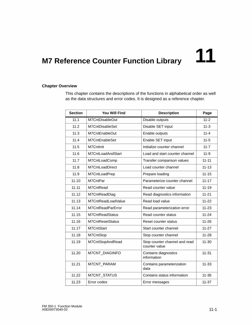
11-1FM 350-1 Function ModuleA5E00073040-02
M7 Reference Counter Function Library
Chapter Overview
This chapter contains the descriptions of the functions in alphabetical order as wellas the data structures and error codes. It is designed as a reference chapter.
Section You Will Find ÁÁÁÁÁÁÁÁÁÁÁÁÁÁÁÁÁÁ
Description Page
11.1 M7CntDisableOut ÁÁÁÁÁÁÁÁÁÁÁÁÁÁÁÁÁÁ
Disable outputs 11-2
11.2 M7CntDisableSet ÁÁÁÁÁÁÁÁÁÁÁÁÁÁÁÁÁÁ
Disable SET input 11-3
11.3 M7CntEnableOut ÁÁÁÁÁÁÁÁÁÁÁÁÁÁÁÁÁÁ
Enable outputs 11-4
11.4 M7CntEnableSetÁÁÁÁÁÁÁÁÁÁÁÁÁÁÁÁÁÁ
Enable SET input 11-5
11.5 M7CntInitÁÁÁÁÁÁÁÁÁÁÁÁÁÁÁÁÁÁ
Initialize counter channel 11-7
11.6 M7CntLoadAndStartÁÁÁÁÁÁÁÁÁÁÁÁÁÁÁÁÁÁLoad and start counter channel 11-9
11.7 M7CntLoadCompÁÁÁÁÁÁÁÁÁÁÁÁÁÁÁÁÁÁTransfer comparison values 11-11
11.8 M7CntLoadDirectÁÁÁÁÁÁÁÁÁÁÁÁÁÁÁÁÁÁÁÁÁÁÁÁÁÁÁ
Load counter channel 11-13
11.9 M7CntLoadPrep ÁÁÁÁÁÁÁÁÁÁÁÁÁÁÁÁÁÁ
Prepare loading 11-15
11.10 M7CntPar ÁÁÁÁÁÁÁÁÁÁÁÁÁÁÁÁÁÁ
Parameterize counter channel 11-17
11.11 M7CntRead ÁÁÁÁÁÁÁÁÁÁÁÁÁÁÁÁÁÁ
Read counter value 11-19
11.12 M7CntReadDiag ÁÁÁÁÁÁÁÁÁÁÁÁÁÁÁÁÁÁ
Read diagnostics information 11-21
11.13 M7CntReadLoadValue ÁÁÁÁÁÁÁÁÁÁÁÁÁÁÁÁÁÁ
Read load value 11-22
11.14 M7CntReadParError ÁÁÁÁÁÁÁÁÁÁÁÁÁÁÁÁÁÁ
Read parameterization error 11-23
11.15 M7CntReadStatus ÁÁÁÁÁÁÁÁÁÁÁÁÁÁÁÁÁÁ
Read counter status 11-24
11.16 M7CntResetStatus ÁÁÁÁÁÁÁÁÁÁÁÁÁÁÁÁÁÁ
Reset counter status 11-26
11.17 M7CntStart ÁÁÁÁÁÁÁÁÁÁÁÁÁÁÁÁÁÁ
Start counter channel 11-27
11.18 M7CntStopÁÁÁÁÁÁÁÁÁÁÁÁÁÁÁÁÁÁ
Stop counter channel 11-28
11.19 M7CntStopAndReadÁÁÁÁÁÁÁÁÁÁÁÁÁÁÁÁÁÁÁÁÁÁÁÁÁÁÁ
Stop counter channel and readcounter value
11-30
11.20 M7CNT_DIAGINFO Contains diagnosticsinformation
11-31
11.21 M7CNT_PARAM Contains parameterizationdata
11-33
11.22 M7CNT_STATUS Contains status information 11-36
11.23 Error codes Error messages 11-37
11
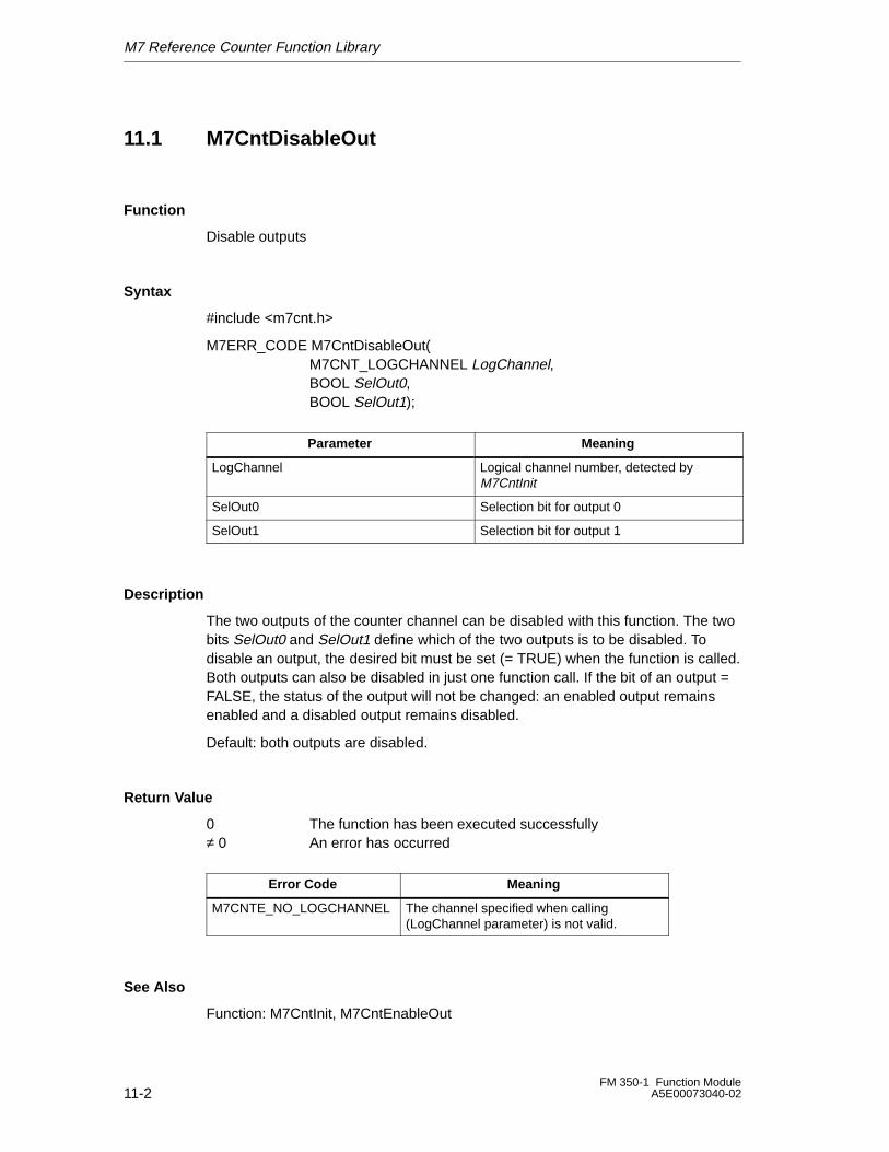
M7 Reference Counter Function Library
11-2FM 350-1 Function Module
A5E00073040-02
11.1 M7CntDisableOut
Function
Disable outputs
Syntax
#include <m7cnt.h>
M7ERR_CODE M7CntDisableOut(M7CNT_LOGCHANNEL LogChannel,BOOL SelOut0, BOOL SelOut1);
ÁÁÁÁÁÁÁÁÁÁÁÁÁÁÁÁÁÁÁÁÁÁÁÁÁÁ
Parameter ÁÁÁÁÁÁÁÁÁÁÁÁÁÁÁÁÁÁÁÁÁÁÁÁÁÁ
Meaning
ÁÁÁÁÁÁÁÁÁÁÁÁÁÁÁÁÁÁÁÁÁÁÁÁÁÁÁÁÁÁÁÁÁÁÁÁÁÁÁ
LogChannel ÁÁÁÁÁÁÁÁÁÁÁÁÁÁÁÁÁÁÁÁÁÁÁÁÁÁÁÁÁÁÁÁÁÁÁÁÁÁÁ
Logical channel number, detected byM7CntInit
ÁÁÁÁÁÁÁÁÁÁÁÁÁÁÁÁÁÁÁÁÁÁÁÁÁÁ
SelOut0 ÁÁÁÁÁÁÁÁÁÁÁÁÁÁÁÁÁÁÁÁÁÁÁÁÁÁ
Selection bit for output 0
ÁÁÁÁÁÁÁÁÁÁÁÁÁÁÁÁÁÁÁÁÁÁÁÁÁÁ
SelOut1 ÁÁÁÁÁÁÁÁÁÁÁÁÁÁÁÁÁÁÁÁÁÁÁÁÁÁ
Selection bit for output 1
Description
The two outputs of the counter channel can be disabled with this function. The twobits SelOut0 and SelOut1 define which of the two outputs is to be disabled. Todisable an output, the desired bit must be set (= TRUE) when the function is called.Both outputs can also be disabled in just one function call. If the bit of an output =FALSE, the status of the output will not be changed: an enabled output remainsenabled and a disabled output remains disabled.
Default: both outputs are disabled.
Return Value
0 The function has been executed successfully≠ 0 An error has occurred
Error Code Meaning
M7CNTE_NO_LOGCHANNEL The channel specified when calling(LogChannel parameter) is not valid.
See Also
Function: M7CntInit, M7CntEnableOut
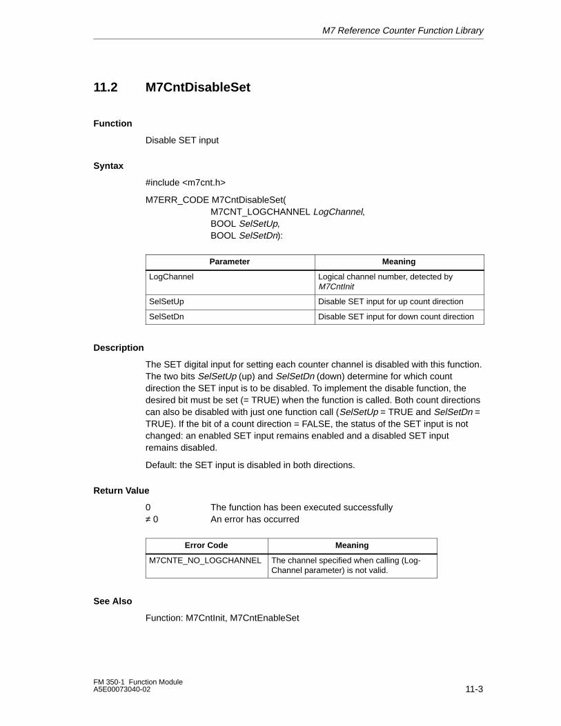
M7 Reference Counter Function Library
11-3FM 350-1 Function ModuleA5E00073040-02
11.2 M7CntDisableSet
Function
Disable SET input
Syntax
#include <m7cnt.h>
M7ERR_CODE M7CntDisableSet(M7CNT_LOGCHANNEL LogChannel,BOOL SelSetUp,BOOL SelSetDn):
ÁÁÁÁÁÁÁÁÁÁÁÁÁÁÁÁÁÁÁÁÁÁÁÁÁÁ
Parameter ÁÁÁÁÁÁÁÁÁÁÁÁÁÁÁÁÁÁÁÁÁÁÁÁÁÁ
Meaning
ÁÁÁÁÁÁÁÁÁÁÁÁÁÁÁÁÁÁÁÁÁÁÁÁÁÁ
LogChannel ÁÁÁÁÁÁÁÁÁÁÁÁÁÁÁÁÁÁÁÁÁÁÁÁÁÁ
Logical channel number, detected byM7CntInitÁÁÁÁÁÁÁÁÁÁÁÁÁ
ÁÁÁÁÁÁÁÁÁÁÁÁÁÁÁÁÁÁÁÁÁÁÁÁÁÁ
SelSetUpÁÁÁÁÁÁÁÁÁÁÁÁÁÁÁÁÁÁÁÁÁÁÁÁÁÁÁÁÁÁÁÁÁÁÁÁÁÁÁ
Disable SET input for up count direction
ÁÁÁÁÁÁÁÁÁÁÁÁÁÁÁÁÁÁÁÁÁÁÁÁÁÁ
SelSetDn ÁÁÁÁÁÁÁÁÁÁÁÁÁÁÁÁÁÁÁÁÁÁÁÁÁÁ
Disable SET input for down count direction
Description
The SET digital input for setting each counter channel is disabled with this function.The two bits SelSetUp (up) and SelSetDn (down) determine for which countdirection the SET input is to be disabled. To implement the disable function, thedesired bit must be set (= TRUE) when the function is called. Both count directionscan also be disabled with just one function call (SelSetUp = TRUE and SelSetDn =TRUE). If the bit of a count direction = FALSE, the status of the SET input is notchanged: an enabled SET input remains enabled and a disabled SET inputremains disabled.
Default: the SET input is disabled in both directions.
Return Value
0 The function has been executed successfully≠ 0 An error has occurred
Error Code Meaning
M7CNTE_NO_LOGCHANNEL The channel specified when calling (Log-Channel parameter) is not valid.
See Also
Function: M7CntInit, M7CntEnableSet
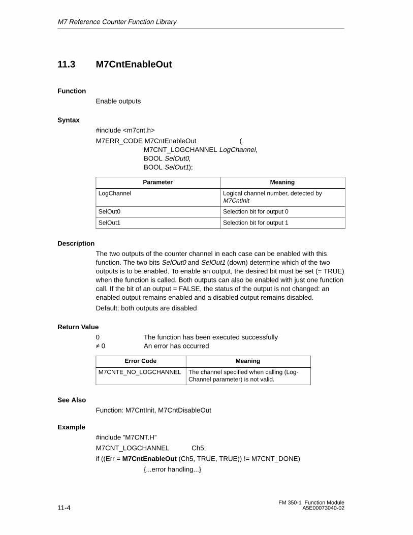
M7 Reference Counter Function Library
11-4FM 350-1 Function Module
A5E00073040-02
11.3 M7CntEnableOut
Function
Enable outputs
Syntax
#include <m7cnt.h>
M7ERR_CODE M7CntEnableOut (M7CNT_LOGCHANNEL LogChannel,BOOL SelOut0, BOOL SelOut1);
ÁÁÁÁÁÁÁÁÁÁÁÁÁÁÁÁÁÁÁÁÁÁÁÁÁÁ
Parameter ÁÁÁÁÁÁÁÁÁÁÁÁÁÁÁÁÁÁÁÁÁÁÁÁÁÁ
Meaning
ÁÁÁÁÁÁÁÁÁÁÁÁÁÁÁÁÁÁÁÁÁÁÁÁÁÁ
LogChannel ÁÁÁÁÁÁÁÁÁÁÁÁÁÁÁÁÁÁÁÁÁÁÁÁÁÁ
Logical channel number, detected byM7CntInitÁÁÁÁÁÁÁÁÁÁÁÁÁ
ÁÁÁÁÁÁÁÁÁÁÁÁÁSelOut0ÁÁÁÁÁÁÁÁÁÁÁÁÁÁÁÁÁÁÁÁÁÁÁÁÁÁSelection bit for output 0ÁÁÁÁÁÁÁÁÁÁÁÁÁ
ÁÁÁÁÁÁÁÁÁÁÁÁÁÁÁÁÁÁÁÁÁÁÁÁÁÁ
SelOut1ÁÁÁÁÁÁÁÁÁÁÁÁÁÁÁÁÁÁÁÁÁÁÁÁÁÁÁÁÁÁÁÁÁÁÁÁÁÁÁ
Selection bit for output 1
Description
The two outputs of the counter channel in each case can be enabled with thisfunction. The two bits SelOut0 and SelOut1 (down) determine which of the twooutputs is to be enabled. To enable an output, the desired bit must be set (= TRUE)when the function is called. Both outputs can also be enabled with just one functioncall. If the bit of an output = FALSE, the status of the output is not changed: anenabled output remains enabled and a disabled output remains disabled.
Default: both outputs are disabled
Return Value
0 The function has been executed successfully≠ 0 An error has occurred
Error Code Meaning
M7CNTE_NO_LOGCHANNEL The channel specified when calling (Log-Channel parameter) is not valid.
See Also
Function: M7CntInit, M7CntDisableOut
Example
#include ”M7CNT.H”
M7CNT_LOGCHANNEL Ch5;
if ((Err = M7CntEnableOut (Ch5, TRUE, TRUE)) != M7CNT_DONE)
{...error handling...}
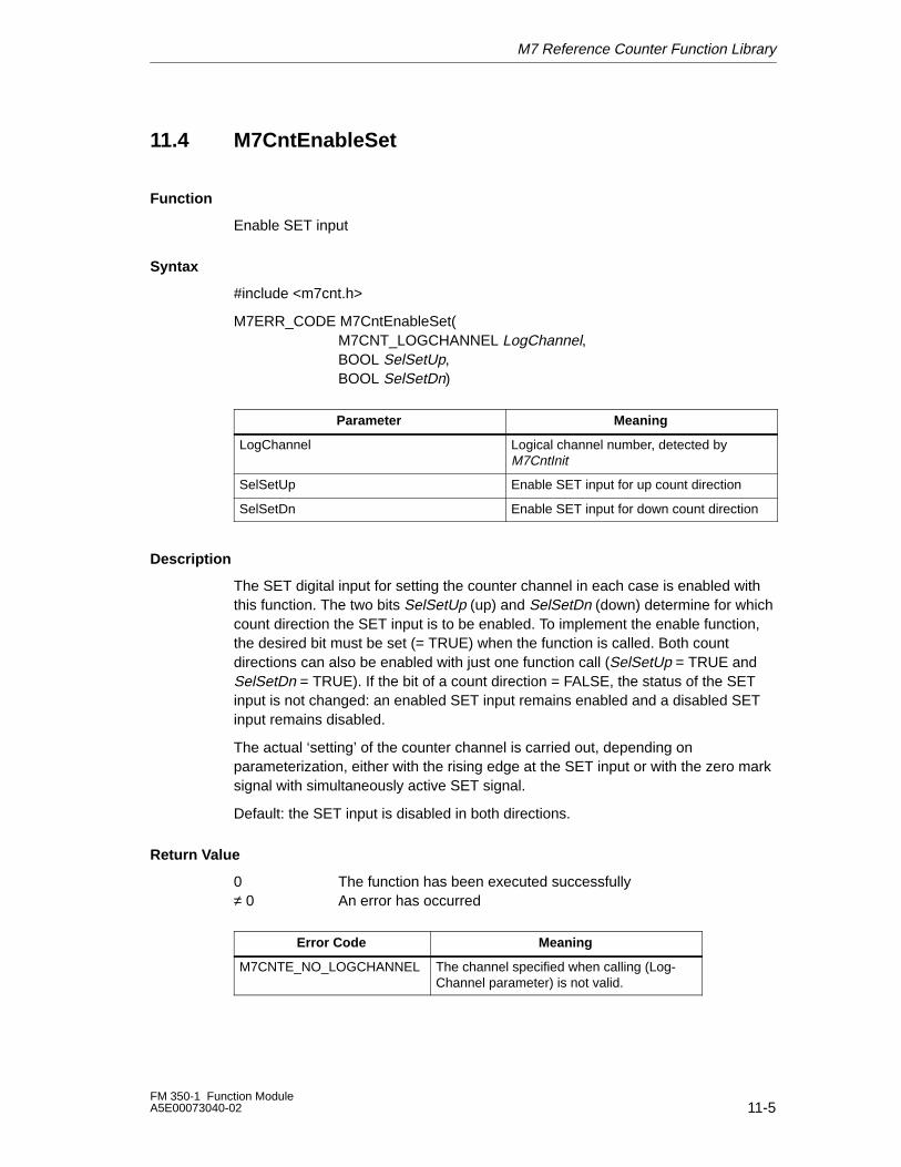
M7 Reference Counter Function Library
11-5FM 350-1 Function ModuleA5E00073040-02
11.4 M7CntEnableSet
Function
Enable SET input
Syntax
#include <m7cnt.h>
M7ERR_CODE M7CntEnableSet(M7CNT_LOGCHANNEL LogChannel,BOOL SelSetUp,BOOL SelSetDn)
ÁÁÁÁÁÁÁÁÁÁÁÁÁÁÁÁÁÁÁÁÁÁÁÁÁÁ
Parameter ÁÁÁÁÁÁÁÁÁÁÁÁÁÁÁÁÁÁÁÁÁÁÁÁÁÁ
Meaning
ÁÁÁÁÁÁÁÁÁÁÁÁÁÁÁÁÁÁÁÁÁÁÁÁÁÁ
LogChannel ÁÁÁÁÁÁÁÁÁÁÁÁÁÁÁÁÁÁÁÁÁÁÁÁÁÁ
Logical channel number, detected byM7CntInitÁÁÁÁÁÁÁÁÁÁÁÁÁ
ÁÁÁÁÁÁÁÁÁÁÁÁÁÁÁÁÁÁÁÁÁÁÁÁÁÁ
SelSetUpÁÁÁÁÁÁÁÁÁÁÁÁÁÁÁÁÁÁÁÁÁÁÁÁÁÁÁÁÁÁÁÁÁÁÁÁÁÁÁ
Enable SET input for up count direction
ÁÁÁÁÁÁÁÁÁÁÁÁÁÁÁÁÁÁÁÁÁÁÁÁÁÁ
SelSetDn ÁÁÁÁÁÁÁÁÁÁÁÁÁÁÁÁÁÁÁÁÁÁÁÁÁÁ
Enable SET input for down count direction
Description
The SET digital input for setting the counter channel in each case is enabled withthis function. The two bits SelSetUp (up) and SelSetDn (down) determine for whichcount direction the SET input is to be enabled. To implement the enable function,the desired bit must be set (= TRUE) when the function is called. Both countdirections can also be enabled with just one function call (SelSetUp = TRUE andSelSetDn = TRUE). If the bit of a count direction = FALSE, the status of the SETinput is not changed: an enabled SET input remains enabled and a disabled SETinput remains disabled.
The actual ‘setting’ of the counter channel is carried out, depending onparameterization, either with the rising edge at the SET input or with the zero marksignal with simultaneously active SET signal.
Default: the SET input is disabled in both directions.
Return Value
0 The function has been executed successfully≠ 0 An error has occurred
Error Code Meaning
M7CNTE_NO_LOGCHANNEL The channel specified when calling (Log-Channel parameter) is not valid.

M7 Reference Counter Function Library
11-6FM 350-1 Function Module
A5E00073040-02
See Also
Function: M7CntInit, M7CntEnableSet
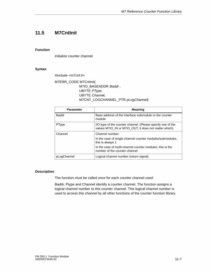
M7 Reference Counter Function Library
11-7FM 350-1 Function ModuleA5E00073040-02
11.5 M7CntInit
Function
Initialize counter channel
Syntax
#include <m7cnt.h>
M7ERR_CODE M7CntInit(M7IO_BASEADDR Baddr , UBYTE PType, UBYTE Channel, M7CNT_LOGCHANNEL_PTR pLogChannel);
ÁÁÁÁÁÁÁÁÁÁÁÁÁÁÁÁ
Parameter ÁÁÁÁÁÁÁÁÁÁÁÁÁÁÁÁÁÁÁÁÁÁÁÁÁÁÁÁÁÁÁÁÁÁÁÁ
Meaning
ÁÁÁÁÁÁÁÁÁÁÁÁÁÁÁÁÁÁÁÁÁÁÁÁ
Baddr ÁÁÁÁÁÁÁÁÁÁÁÁÁÁÁÁÁÁÁÁÁÁÁÁÁÁÁÁÁÁÁÁÁÁÁÁÁÁÁÁÁÁÁÁÁÁÁÁÁÁÁÁÁÁ
Base address of the interface submodule or the countermodule
ÁÁÁÁÁÁÁÁÁÁÁÁÁÁÁÁ
PType ÁÁÁÁÁÁÁÁÁÁÁÁÁÁÁÁÁÁÁÁÁÁÁÁÁÁÁÁÁÁÁÁÁÁÁÁ
I/O type of the counter channel. (Please specify one of thevalues M7IO_IN or M7IO_OUT, it does not matter which)
ÁÁÁÁÁÁÁÁÁÁÁÁÁÁÁÁÁÁÁÁÁÁÁÁÁÁÁÁÁÁÁÁÁÁÁÁÁÁÁÁÁÁÁÁÁÁÁÁ
ChannelÁÁÁÁÁÁÁÁÁÁÁÁÁÁÁÁÁÁÁÁÁÁÁÁÁÁÁÁÁÁÁÁÁÁÁÁÁÁÁÁÁÁÁÁÁÁÁÁÁÁÁÁÁÁÁÁÁÁÁÁÁÁÁÁÁÁÁÁÁÁÁÁÁÁÁÁÁÁÁÁÁÁÁÁÁÁÁÁÁÁÁÁÁÁÁÁÁÁÁÁÁÁÁÁÁÁÁÁ
Channel number:
In the case of single-channel counter modules/submodules,this is always 1
In the case of multi-channel counter modules, this is thenumber of the counter channel
ÁÁÁÁÁÁÁÁÁÁÁÁÁÁÁÁ
pLogChannel ÁÁÁÁÁÁÁÁÁÁÁÁÁÁÁÁÁÁÁÁÁÁÁÁÁÁÁÁÁÁÁÁÁÁÁÁ
Logical channel number (return signal)
Description
The function must be called once for each counter channel used.
Baddr, Ptype and Channel identify a counter channel. The function assigns alogical channel number to this counter channel. This logical channel number isused to access this channel by all other functions of the counter function library.
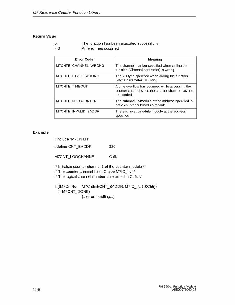
M7 Reference Counter Function Library
11-8FM 350-1 Function Module
A5E00073040-02
Return Value
0 The function has been executed successfully≠ 0 An error has occurred
Error Code Meaning
M7CNTE_CHANNEL_WRONG The channel number specified when calling thefunction (Channel parameter) is wrong
M7CNTE_PTYPE_WRONG The I/O type specified when calling the function(Ptype parameter) is wrong
M7CNTE_TIMEOUT A time overflow has occurred while accessing thecounter channel since the counter channel has notresponded.
M7CNTE_NO_COUNTER The submodule/module at the address specified isnot a counter submodule/module.
M7CNTE_INVALID_BADDR There is no submodule/module at the addressspecified
Example
#include ”M7CNT.H”
#define CNT_BADDR 320
M7CNT_LOGCHANNEL Ch5;
/* Initialize counter channel 1 of the counter module *//* The counter channel has I/O type M7IO_IN.*//* The logical channel number is returned in Ch5. */
if ((M7CntRet = M7CntInit(CNT_BADDR, M7IO_IN,1,&Ch5)) != M7CNT_DONE)
{...error handling...}
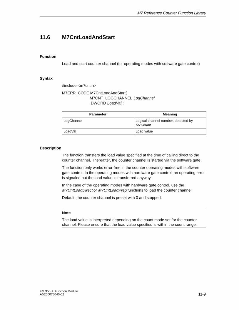
M7 Reference Counter Function Library
11-9FM 350-1 Function ModuleA5E00073040-02
11.6 M7CntLoadAndStart
Function
Load and start counter channel (for operating modes with software gate control)
Syntax
#include <m7cnt.h>
M7ERR_CODE M7CntLoadAndStart(M7CNT_LOGCHANNEL LogChannel, DWORD LoadVal);
ÁÁÁÁÁÁÁÁÁÁÁÁÁÁÁÁÁÁÁÁÁÁÁÁÁÁ
Parameter ÁÁÁÁÁÁÁÁÁÁÁÁÁÁÁÁÁÁÁÁÁÁÁÁÁÁ
MeaningÁÁÁÁÁÁÁÁÁÁÁÁÁÁÁÁÁÁÁÁÁÁÁÁÁÁÁÁÁÁÁÁÁÁÁÁÁÁÁ
LogChannel ÁÁÁÁÁÁÁÁÁÁÁÁÁÁÁÁÁÁÁÁÁÁÁÁÁÁÁÁÁÁÁÁÁÁÁÁÁÁÁ
Logical channel number, detected byM7CntInit
ÁÁÁÁÁÁÁÁÁÁÁÁÁÁÁÁÁÁÁÁÁÁÁÁÁÁ
LoadVal ÁÁÁÁÁÁÁÁÁÁÁÁÁÁÁÁÁÁÁÁÁÁÁÁÁÁ
Load value
Description
The function transfers the load value specified at the time of calling direct to thecounter channel. Thereafter, the counter channel is started via the software gate.
The function only works error-free in the counter operating modes with softwaregate control. In the operating modes with hardware gate control, an operating erroris signaled but the load value is transferred anyway.
In the case of the operating modes with hardware gate control, use theM7CntLoadDirect or M7CntLoadPrep functions to load the counter channel.
Default: the counter channel is preset with 0 and stopped.
Note
The load value is interpreted depending on the count mode set for the counterchannel. Please ensure that the load value specified is within the count range.
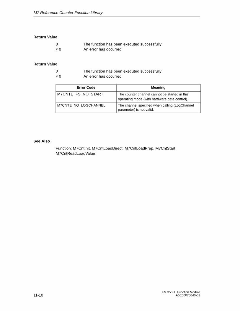
M7 Reference Counter Function Library
11-10FM 350-1 Function Module
A5E00073040-02
Return Value
0 The function has been executed successfully≠ 0 An error has occurred
Return Value
0 The function has been executed successfully≠ 0 An error has occurred
Error Code Meaning
M7CNTE_FS_NO_START The counter channel cannot be started in thisoperating mode (with hardware gate control).
M7CNTE_NO_LOGCHANNEL The channel specified when calling (LogChannelparameter) is not valid.
See Also
Function: M7CntInit, M7CntLoadDirect, M7CntLoadPrep, M7CntStart, M7CntReadLoadValue
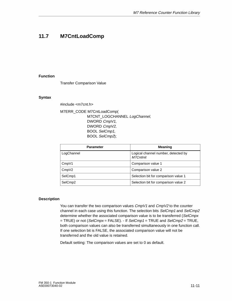
M7 Reference Counter Function Library
11-11FM 350-1 Function ModuleA5E00073040-02
11.7 M7CntLoadComp
Function
Transfer Comparison Value
Syntax
#include <m7cnt.h>
M7ERR_CODE M7CntLoadComp(M7CNT_LOGCHANNEL LogChannel,DWORD CmpV1, DWORD CmpV2,BOOL SelCmp1, BOOL SelCmp2);
ÁÁÁÁÁÁÁÁÁÁÁÁÁÁÁÁÁÁÁÁÁÁÁÁÁÁ
ParameterÁÁÁÁÁÁÁÁÁÁÁÁÁÁÁÁÁÁÁÁÁÁÁÁÁÁ
MeaningÁÁÁÁÁÁÁÁÁÁÁÁÁÁÁÁÁÁÁÁÁÁÁÁÁÁÁÁÁÁÁÁÁÁÁÁÁÁÁ
LogChannelÁÁÁÁÁÁÁÁÁÁÁÁÁÁÁÁÁÁÁÁÁÁÁÁÁÁÁÁÁÁÁÁÁÁÁÁÁÁÁ
Logical channel number, detected byM7CntInit
ÁÁÁÁÁÁÁÁÁÁÁÁÁÁÁÁÁÁÁÁÁÁÁÁÁÁ
CmpV1 ÁÁÁÁÁÁÁÁÁÁÁÁÁÁÁÁÁÁÁÁÁÁÁÁÁÁ
Comparison value 1ÁÁÁÁÁÁÁÁÁÁÁÁÁÁÁÁÁÁÁÁÁÁÁÁÁÁ
CmpV2 ÁÁÁÁÁÁÁÁÁÁÁÁÁÁÁÁÁÁÁÁÁÁÁÁÁÁ
Comparison value 2ÁÁÁÁÁÁÁÁÁÁÁÁÁÁÁÁÁÁÁÁÁÁÁÁÁÁ
SelCmp1ÁÁÁÁÁÁÁÁÁÁÁÁÁÁÁÁÁÁÁÁÁÁÁÁÁÁ
Selection bit for comparison value 1ÁÁÁÁÁÁÁÁÁÁÁÁÁÁÁÁÁÁÁÁÁÁÁÁÁÁ
SelCmp2ÁÁÁÁÁÁÁÁÁÁÁÁÁÁÁÁÁÁÁÁÁÁÁÁÁÁ
Selection bit for comparison value 2
Description
You can transfer the two comparison values CmpV1 and CmpV2 to the counterchannel in each case using this function. The selection bits SelCmp1 and SelCmp2determine whether the associated comparison value is to be transferred (SelCmpx= TRUE) or not (SelCmpx = FALSE). - If SelCmp1 = TRUE and SelCmp2 = TRUE,both comparison values can also be transferred simultaneously in one function call.If one selection bit is FALSE, the associated comparison value will not betransferred and the old value is retained.
Default setting: The comparison values are set to 0 as default.
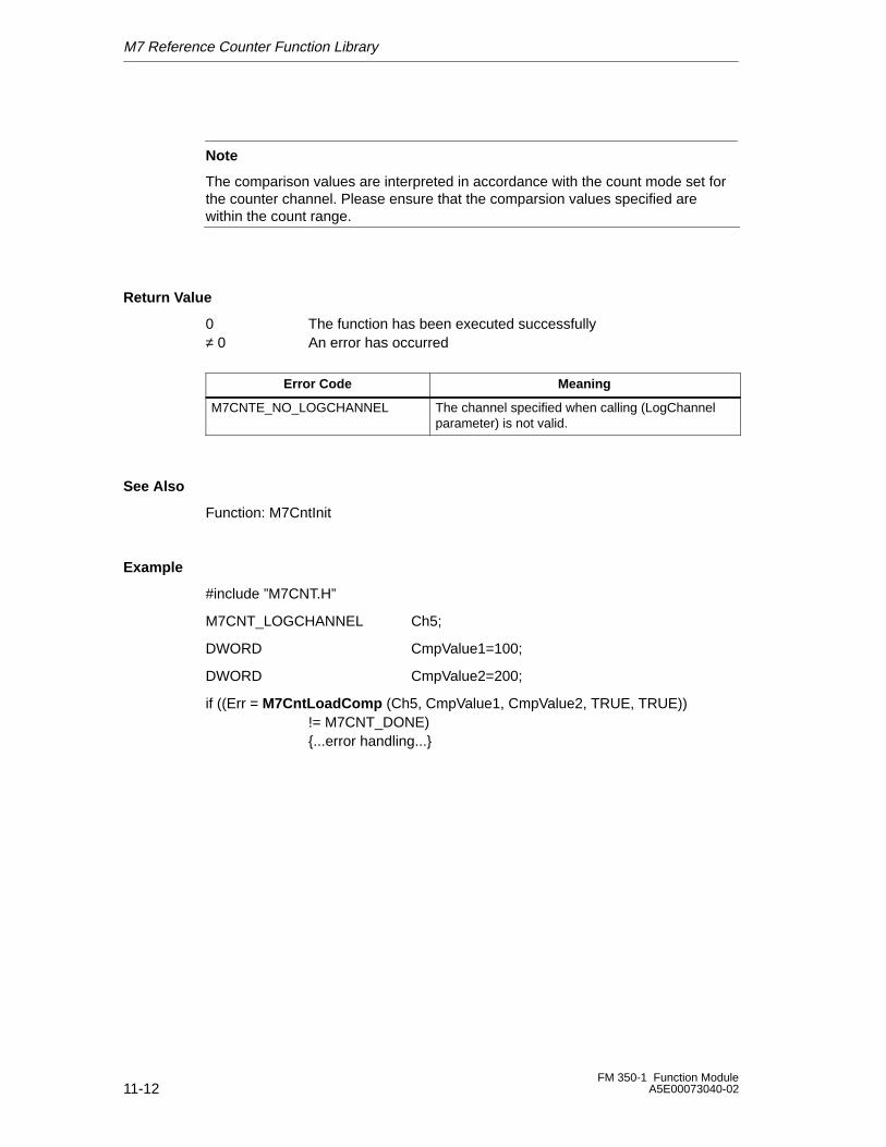
M7 Reference Counter Function Library
11-12FM 350-1 Function Module
A5E00073040-02
Note
The comparison values are interpreted in accordance with the count mode set forthe counter channel. Please ensure that the comparsion values specified arewithin the count range.
Return Value
0 The function has been executed successfully≠ 0 An error has occurred
Error Code Meaning
M7CNTE_NO_LOGCHANNEL The channel specified when calling (LogChannelparameter) is not valid.
See Also
Function: M7CntInit
Example
#include ”M7CNT.H”
M7CNT_LOGCHANNEL Ch5;
DWORD CmpValue1=100;
DWORD CmpValue2=200;
if ((Err = M7CntLoadComp (Ch5, CmpValue1, CmpValue2, TRUE, TRUE))!= M7CNT_DONE){...error handling...}
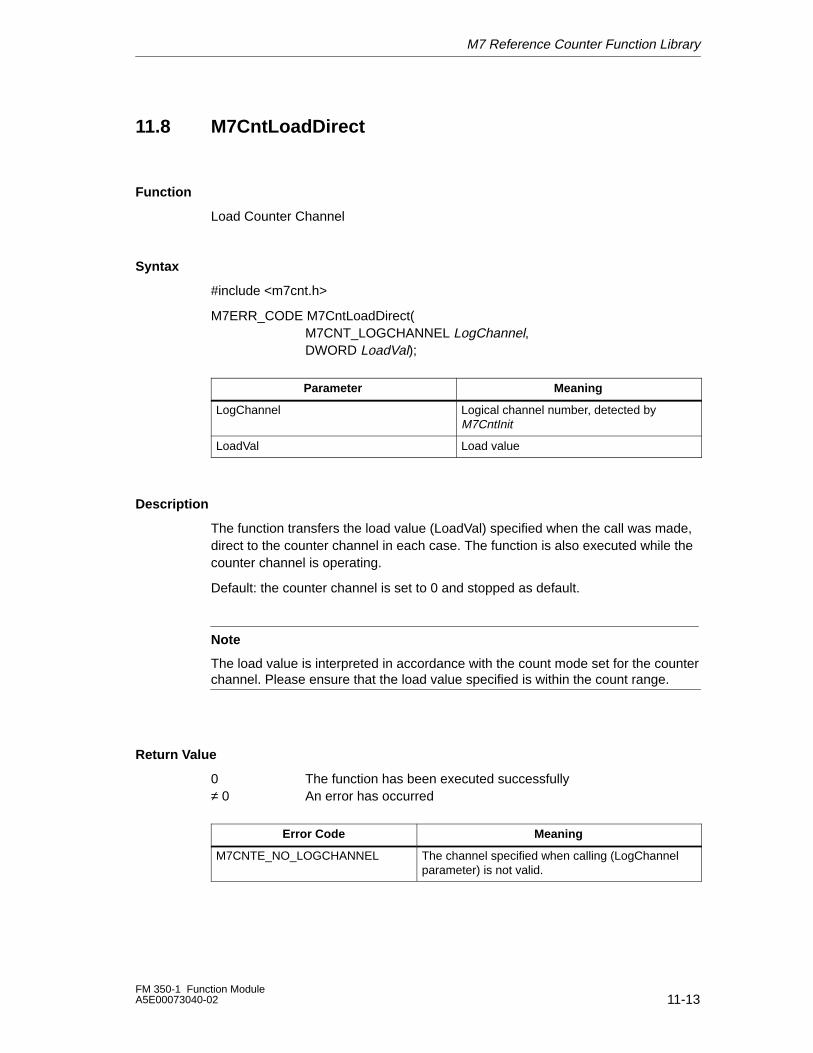
M7 Reference Counter Function Library
11-13FM 350-1 Function ModuleA5E00073040-02
11.8 M7CntLoadDirect
Function
Load Counter Channel
Syntax
#include <m7cnt.h>
M7ERR_CODE M7CntLoadDirect(M7CNT_LOGCHANNEL LogChannel,DWORD LoadVal);
ÁÁÁÁÁÁÁÁÁÁÁÁÁÁÁÁÁÁÁÁÁÁÁÁÁÁ
Parameter ÁÁÁÁÁÁÁÁÁÁÁÁÁÁÁÁÁÁÁÁÁÁÁÁÁÁ
MeaningÁÁÁÁÁÁÁÁÁÁÁÁÁÁÁÁÁÁÁÁÁÁÁÁÁÁÁÁÁÁÁÁÁÁÁÁÁÁÁ
LogChannel ÁÁÁÁÁÁÁÁÁÁÁÁÁÁÁÁÁÁÁÁÁÁÁÁÁÁÁÁÁÁÁÁÁÁÁÁÁÁÁ
Logical channel number, detected byM7CntInit
ÁÁÁÁÁÁÁÁÁÁÁÁÁÁÁÁÁÁÁÁÁÁÁÁÁÁ
LoadVal ÁÁÁÁÁÁÁÁÁÁÁÁÁÁÁÁÁÁÁÁÁÁÁÁÁÁ
Load value
Description
The function transfers the load value (LoadVal) specified when the call was made,direct to the counter channel in each case. The function is also executed while thecounter channel is operating.
Default: the counter channel is set to 0 and stopped as default.
Note
The load value is interpreted in accordance with the count mode set for the counterchannel. Please ensure that the load value specified is within the count range.
Return Value
0 The function has been executed successfully≠ 0 An error has occurred
Error Code Meaning
M7CNTE_NO_LOGCHANNEL The channel specified when calling (LogChannelparameter) is not valid.
M7 Reference Counter Function Library
11-14FM 350-1 Function Module
A5E00073040-02
See Also
Function: M7CntInit, M7CntLoadAndStart, M7CntLoadPrep, M7CntReadLoadValue
Example
#include ”M7CNT.H”
M7CNT_LOGCHANNEL Ch5;
DWORD LoadValue=100;
if ((Err = M7CntLoadDirect (Ch5, LoadValue)) != M7CNT_DONE){...error handling...}
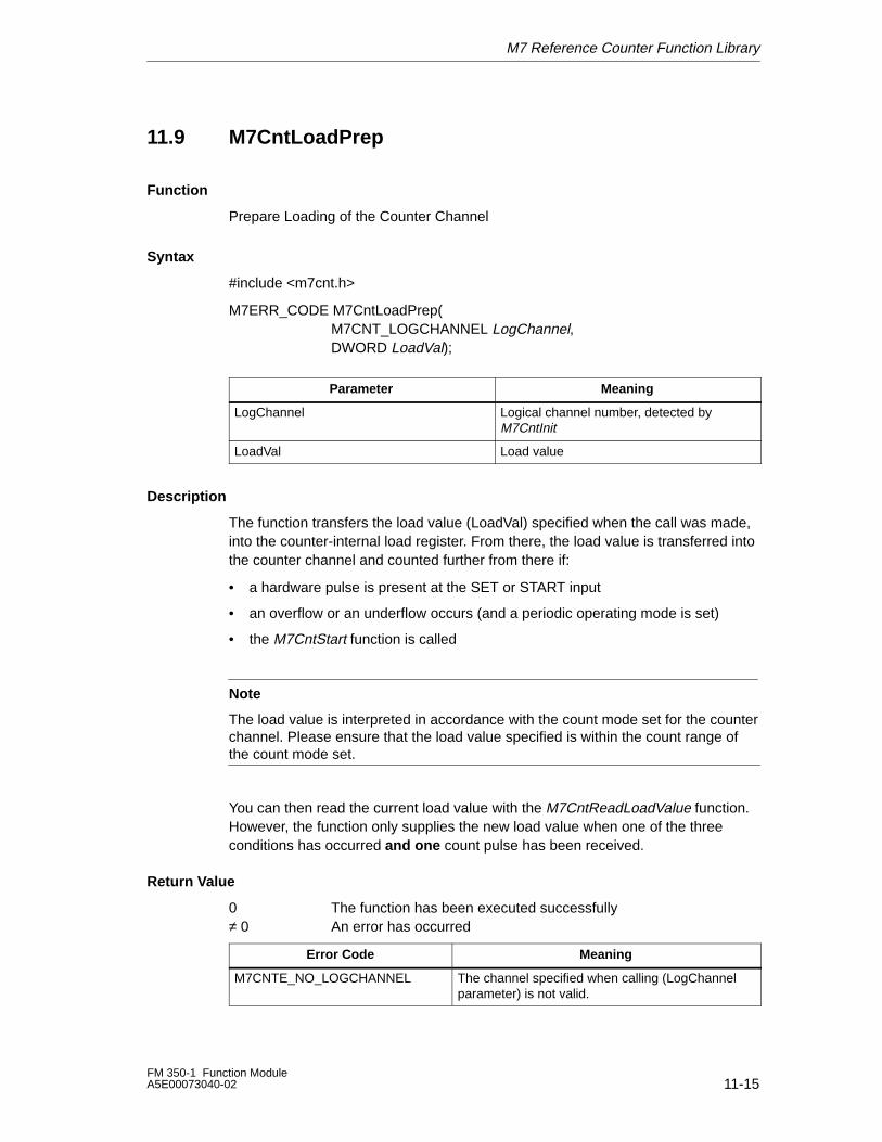
M7 Reference Counter Function Library
11-15FM 350-1 Function ModuleA5E00073040-02
11.9 M7CntLoadPrep
Function
Prepare Loading of the Counter Channel
Syntax
#include <m7cnt.h>
M7ERR_CODE M7CntLoadPrep(M7CNT_LOGCHANNEL LogChannel, DWORD LoadVal);
ÁÁÁÁÁÁÁÁÁÁÁÁÁÁÁÁÁÁÁÁÁÁÁÁÁÁ
Parameter ÁÁÁÁÁÁÁÁÁÁÁÁÁÁÁÁÁÁÁÁÁÁÁÁÁÁ
Meaning
ÁÁÁÁÁÁÁÁÁÁÁÁÁÁÁÁÁÁÁÁÁÁÁÁÁÁ
LogChannel ÁÁÁÁÁÁÁÁÁÁÁÁÁÁÁÁÁÁÁÁÁÁÁÁÁÁ
Logical channel number, detected byM7CntInitÁÁÁÁÁÁÁÁÁÁÁÁÁ
ÁÁÁÁÁÁÁÁÁÁÁÁÁLoadValÁÁÁÁÁÁÁÁÁÁÁÁÁÁÁÁÁÁÁÁÁÁÁÁÁÁLoad value
Description
The function transfers the load value (LoadVal) specified when the call was made,into the counter-internal load register. From there, the load value is transferred intothe counter channel and counted further from there if:
• a hardware pulse is present at the SET or START input
• an overflow or an underflow occurs (and a periodic operating mode is set)
• the M7CntStart function is called
Note
The load value is interpreted in accordance with the count mode set for the counterchannel. Please ensure that the load value specified is within the count range ofthe count mode set.
You can then read the current load value with the M7CntReadLoadValue function.However, the function only supplies the new load value when one of the threeconditions has occurred and one count pulse has been received.
Return Value
0 The function has been executed successfully≠ 0 An error has occurred
Error Code Meaning
M7CNTE_NO_LOGCHANNEL The channel specified when calling (LogChannelparameter) is not valid.

M7 Reference Counter Function Library
11-16FM 350-1 Function Module
A5E00073040-02
See Also
Function: M7CntInit, M7CntLoadAndStart, M7CntLoadDirect, M7CntReadLoadValue
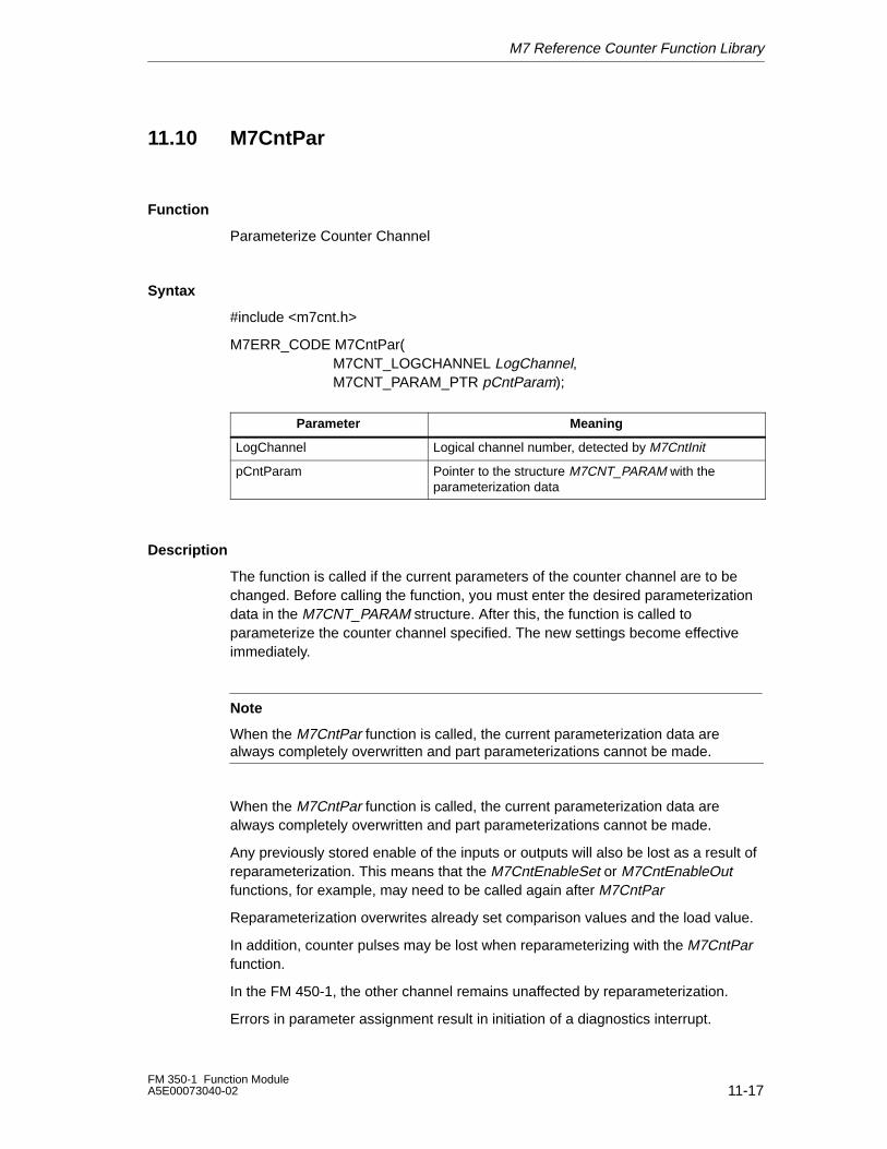
M7 Reference Counter Function Library
11-17FM 350-1 Function ModuleA5E00073040-02
11.10 M7CntPar
Function
Parameterize Counter Channel
Syntax
#include <m7cnt.h>
M7ERR_CODE M7CntPar(M7CNT_LOGCHANNEL LogChannel, M7CNT_PARAM_PTR pCntParam);
ÁÁÁÁÁÁÁÁÁÁÁÁÁÁÁÁÁÁÁÁ
Parameter ÁÁÁÁÁÁÁÁÁÁÁÁÁÁÁÁÁÁÁÁÁÁÁÁÁÁÁÁÁÁÁÁ
MeaningÁÁÁÁÁÁÁÁÁÁÁÁÁÁÁÁÁÁÁÁ
LogChannel ÁÁÁÁÁÁÁÁÁÁÁÁÁÁÁÁÁÁÁÁÁÁÁÁÁÁÁÁÁÁÁÁ
Logical channel number, detected by M7CntInitÁÁÁÁÁÁÁÁÁÁÁÁÁÁÁÁÁÁÁÁÁÁÁÁÁÁÁÁÁÁ
pCntParamÁÁÁÁÁÁÁÁÁÁÁÁÁÁÁÁÁÁÁÁÁÁÁÁÁÁÁÁÁÁÁÁÁÁÁÁÁÁÁÁÁÁÁÁÁÁÁÁ
Pointer to the structure M7CNT_PARAM with theparameterization data
Description
The function is called if the current parameters of the counter channel are to bechanged. Before calling the function, you must enter the desired parameterizationdata in the M7CNT_PARAM structure. After this, the function is called toparameterize the counter channel specified. The new settings become effectiveimmediately.
Note
When the M7CntPar function is called, the current parameterization data arealways completely overwritten and part parameterizations cannot be made.
When the M7CntPar function is called, the current parameterization data arealways completely overwritten and part parameterizations cannot be made.
Any previously stored enable of the inputs or outputs will also be lost as a result ofreparameterization. This means that the M7CntEnableSet or M7CntEnableOutfunctions, for example, may need to be called again after M7CntPar
Reparameterization overwrites already set comparison values and the load value.
In addition, counter pulses may be lost when reparameterizing with the M7CntParfunction.
In the FM 450-1, the other channel remains unaffected by reparameterization.
Errors in parameter assignment result in initiation of a diagnostics interrupt.
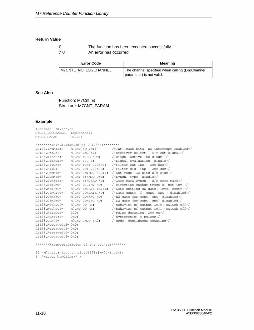
M7 Reference Counter Function Library
11-18FM 350-1 Function Module
A5E00073040-02
Return Value
0 The function has been executed successfully≠ 0 An error has occurred
Error Code Meaning
M7CNTE_NO_LOGCHANNEL The channel specified when calling (LogChannelparameter) is not valid.
See Also
Function: M7CntInitStructure: M7CNT_PARAM
Example
#include <m7cnt.h>M7CNT_LOGCHANNEL LogChannel;M7CNT_PARAM DS128;
/*******Initialization of DS128def*******/DS128.IntMask= M7CNT_NO_INT; /*Int. mask bits: no interrupt enabled*/DS128.EncSel= M7CNT_ENC_5V; /*Receiver select.: 5-V cnt signal*/DS128.WireBrk= M7CNT_WIRE_NON; /*Diagn. active: no diagn.*/DS128.SigEval= M7CNT_SIG_1; /*Signal evaluation: single*/DS128.FilCnt= M7CNT_FCNT_200KHZ; /*Filter cnt inp.: 200 kHz*/DS128.FilDI= M7CNT_FDI_200KHZ; /*Filter dig. inp.: 200 kHz*/DS128.CntMod= M7CNT_CNTMOD_32BIT; /*Cnt mode: 32 bits w/o sign*/DS128.SynMod= M7CNT_SYNMOD_ONE; /*Synch. type: single*/DS128.SynZero= M7CNT_SYNZERO_NO; /*Zero mark synch.: w/o zero mark*/DS128.SigInv= M7CNT_SIGINV_NO; /*Direction change track B: not inv.*/DS128.ModHWG= M7CNT_HWGATE_LEVEL; /*Gate setting HW gate: level-contr.*/DS128.ConGate= M7CNT_CONGATE_NO; /*Gate contr. f. cont. cnt.: disabled*/DS128.ConHWG= M7CNT_CONHWG_NO; /*HW gate for cont. cnt: disabled*/DS128.ConSWG= M7CNT_CONSWG_NO; /*SW gate for cont. cnt: disabled*/DS128.MethDQ0= M7CNT_DQ_AB; /*Behavior of output OUT0: switch off*/DS128.MethDQ1= M7CNT_DQ_AB; /*Behavior of output OUT1: switch off*/DS128.PulsDur= 200; /*Pulse duration: 200 ms*/DS128.HystVal= 0x0; /*Hysteresis: 0 pulses*/DS128.OpMod= M7CNT_CMOD_BA0; /*Mode: continuous counting*/DS128.Reserved12= 0x0;DS128.Reserved13= 0x0;DS128.Reserved14= 0x0;DS128.Reserved15= 0x0;
/******Parameterization of the counter******/
if (M7CntPar(LogChannel,&DS128)!=M7CNT_DONE){ /*error handling*/ }
M7 Reference Counter Function Library
11-19FM 350-1 Function ModuleA5E00073040-02
11.11 M7CntRead
Function
Read Counter Value
Syntax
#include <m7cnt.h>
M7ERR_CODE M7CntRead(M7CNT_LOGCHANNEL LogChannel, DWORD_PTR pActCntV);
ÁÁÁÁÁÁÁÁÁÁÁÁÁÁÁÁÁÁÁÁÁÁÁÁÁÁ
Parameter ÁÁÁÁÁÁÁÁÁÁÁÁÁÁÁÁÁÁÁÁÁÁÁÁÁÁ
Meaning
ÁÁÁÁÁÁÁÁÁÁÁÁÁÁÁÁÁÁÁÁÁÁÁÁÁÁÁÁÁÁÁÁÁÁÁÁÁÁÁ
LogChannel ÁÁÁÁÁÁÁÁÁÁÁÁÁÁÁÁÁÁÁÁÁÁÁÁÁÁÁÁÁÁÁÁÁÁÁÁÁÁÁ
Logical channel number, detected byM7CntInit
ÁÁÁÁÁÁÁÁÁÁÁÁÁÁÁÁÁÁÁÁÁÁÁÁÁÁ
pActCntV ÁÁÁÁÁÁÁÁÁÁÁÁÁÁÁÁÁÁÁÁÁÁÁÁÁÁ
Pointer to current counter status
Description
The current counter status of the counter channel is read and stored in pActCntV.
Return Value
0 The function has been executed successfully≠ 0 An error has occurred
Error Code Meaning
M7CNTE_NO_LOGCHANNEL The channel specified when calling (LogChannel pa-rameter) is not valid.
Note
The macros M7InitISADesc and M7LoadISADWord from the M7-API are availablefor reading the counter status of an IF counter submodule. Access is via thehigh-speed ISA bus.
See Also
Function: M7CntInit, M7CntStopAndRead
M7 Reference Counter Function Library
11-20FM 350-1 Function Module
A5E00073040-02
Example
#include ”M7CNT.H”
M7CNT_LOGCHANNEL Ch5;
DWORD ZaehlerStand;
if ((M7CntRet = M7CntRead (Ch5, &ZaehlerStand)) != M7CNT_DONE){...error handling...}
M7 Reference Counter Function Library
11-21FM 350-1 Function ModuleA5E00073040-02
11.12 M7CntReadDiag
Function
Read Diagnostics Information
Syntax
#include <m7cnt.h>
M7ERR_CODE M7CntReadDiag(M7CNT_LOGCHANNEL LogChannel, M7CNT_DIAGINFO_PTR pDiagInfo);
ÁÁÁÁÁÁÁÁÁÁÁÁÁÁÁÁÁÁÁÁÁÁ
Parameter ÁÁÁÁÁÁÁÁÁÁÁÁÁÁÁÁÁÁÁÁÁÁÁÁÁÁÁÁÁÁ
Meaning
ÁÁÁÁÁÁÁÁÁÁÁÁÁÁÁÁÁÁÁÁÁÁ
LogChannel ÁÁÁÁÁÁÁÁÁÁÁÁÁÁÁÁÁÁÁÁÁÁÁÁÁÁÁÁÁÁ
Logical channel number, detected by M7CntInit
ÁÁÁÁÁÁÁÁÁÁÁÁÁÁÁÁÁÁÁÁÁÁÁÁÁÁÁÁÁÁÁÁÁ
pDiagInfo ÁÁÁÁÁÁÁÁÁÁÁÁÁÁÁÁÁÁÁÁÁÁÁÁÁÁÁÁÁÁÁÁÁÁÁÁÁÁÁÁÁÁÁÁÁ
Pointer to M7CNT_DIAGINFO structure with thediagnostics information
Description
When this function is called, the diagnostics data set DS1 is read and stored inpDiagInfo. You should then call the M7CntReadDiag function if you receive adiagnostics interrupt ‘Error on the channel’ (diagnostics byte 0, bit 3=1). TheM7CNT_DIAGINFO structure supplies you with the diagnostics data set DS1 whichcontains additional channel-specific diagnostics information.
The structure of the diagnostics data set DS1 is explained in Chapter 12.
Return Value
0 The function has been executed successfully≠ 0 An error has occurred
Error Code Meaning
M7CNTE_NO_LOGCHANNEL The channel specified when calling (LogChannelparameter) is not valid.
Example
#include ”M7CNT.H”
M7CNT_LOGCHANNEL Ch5;
M7CNT_DIAGINFO CntDiagInfo;
if ((Err = M7CntReadDiag (Ch5, &CntDiagInfo)) != M7CNT_DONE){...error handling...}
See Also
Function: M7CntInit, M7CntReadParError Structure: M7CNT_DIAGINFO
M7 Reference Counter Function Library
11-22FM 350-1 Function Module
A5E00073040-02
11.13 M7CntReadLoadValue
Function
Read Load Value
Syntax
#include <m7cnt.h>
M7ERR_CODE M7CntReadLoadValue(M7CNT_LOGCHANNEL LogChannel,DWORD_PTR pActLoad);
ÁÁÁÁÁÁÁÁÁÁÁÁÁÁÁÁÁÁÁÁÁÁÁÁÁÁ
Parameter ÁÁÁÁÁÁÁÁÁÁÁÁÁÁÁÁÁÁÁÁÁÁÁÁÁÁ
MeaningÁÁÁÁÁÁÁÁÁÁÁÁÁÁÁÁÁÁÁÁÁÁÁÁÁÁÁÁÁÁÁÁÁÁÁÁÁÁÁ
LogChannel ÁÁÁÁÁÁÁÁÁÁÁÁÁÁÁÁÁÁÁÁÁÁÁÁÁÁÁÁÁÁÁÁÁÁÁÁÁÁÁ
Logical channel number, detected byM7CntInit
ÁÁÁÁÁÁÁÁÁÁÁÁÁÁÁÁÁÁÁÁÁÁÁÁÁÁ
pActLoad ÁÁÁÁÁÁÁÁÁÁÁÁÁÁÁÁÁÁÁÁÁÁÁÁÁÁ
Pointer to the ActLoad load value
Description
The function reads the current load value of the counter channel and stores it inpActLoad.
Return Value
0 The function has been executed successfully≠ 0 An error has occurred
Error Code Meaning
M7CNTE_NO_LOGCHANNEL The channel specified when calling (LogChannelparameter) is not valid.
See Also
Function: M7CntInit, M7CntLoadAndStart, M7CntLoadDirect, M7CntLoadPrep
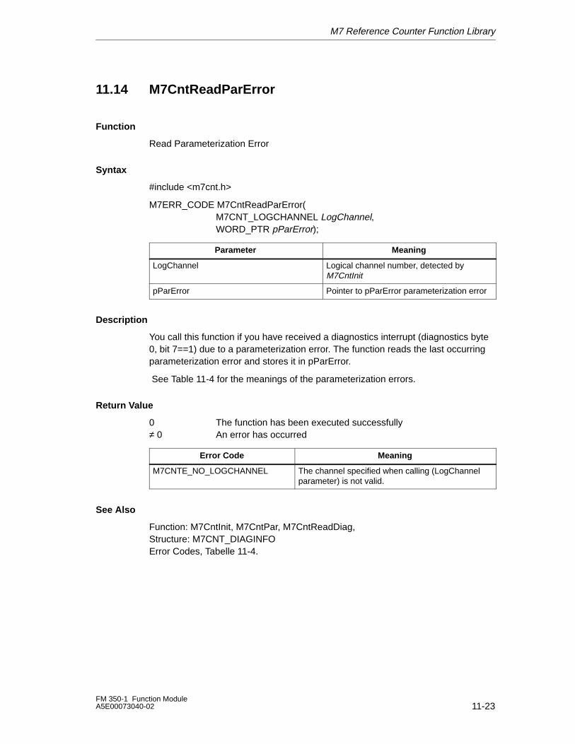
M7 Reference Counter Function Library
11-23FM 350-1 Function ModuleA5E00073040-02
11.14 M7CntReadParError
Function
Read Parameterization Error
Syntax
#include <m7cnt.h>
M7ERR_CODE M7CntReadParError(M7CNT_LOGCHANNEL LogChannel,WORD_PTR pParError);
ÁÁÁÁÁÁÁÁÁÁÁÁÁÁÁÁÁÁÁÁÁÁÁÁÁÁParameter
ÁÁÁÁÁÁÁÁÁÁÁÁÁÁÁÁÁÁÁÁÁÁÁÁÁÁMeaningÁÁÁÁÁÁÁÁÁÁÁÁÁ
ÁÁÁÁÁÁÁÁÁÁÁÁÁÁÁÁÁÁÁÁÁÁÁÁÁÁ
LogChannelÁÁÁÁÁÁÁÁÁÁÁÁÁÁÁÁÁÁÁÁÁÁÁÁÁÁÁÁÁÁÁÁÁÁÁÁÁÁÁ
Logical channel number, detected byM7CntInit
ÁÁÁÁÁÁÁÁÁÁÁÁÁÁÁÁÁÁÁÁÁÁÁÁÁÁ
pParErrorÁÁÁÁÁÁÁÁÁÁÁÁÁÁÁÁÁÁÁÁÁÁÁÁÁÁ
Pointer to pParError parameterization error
Description
You call this function if you have received a diagnostics interrupt (diagnostics byte0, bit 7==1) due to a parameterization error. The function reads the last occurringparameterization error and stores it in pParError.
See Table 11-4 for the meanings of the parameterization errors.
Return Value
0 The function has been executed successfully≠ 0 An error has occurred
Error Code Meaning
M7CNTE_NO_LOGCHANNEL The channel specified when calling (LogChannelparameter) is not valid.
See Also
Function: M7CntInit, M7CntPar, M7CntReadDiag, Structure: M7CNT_DIAGINFOError Codes, Tabelle 11-4.
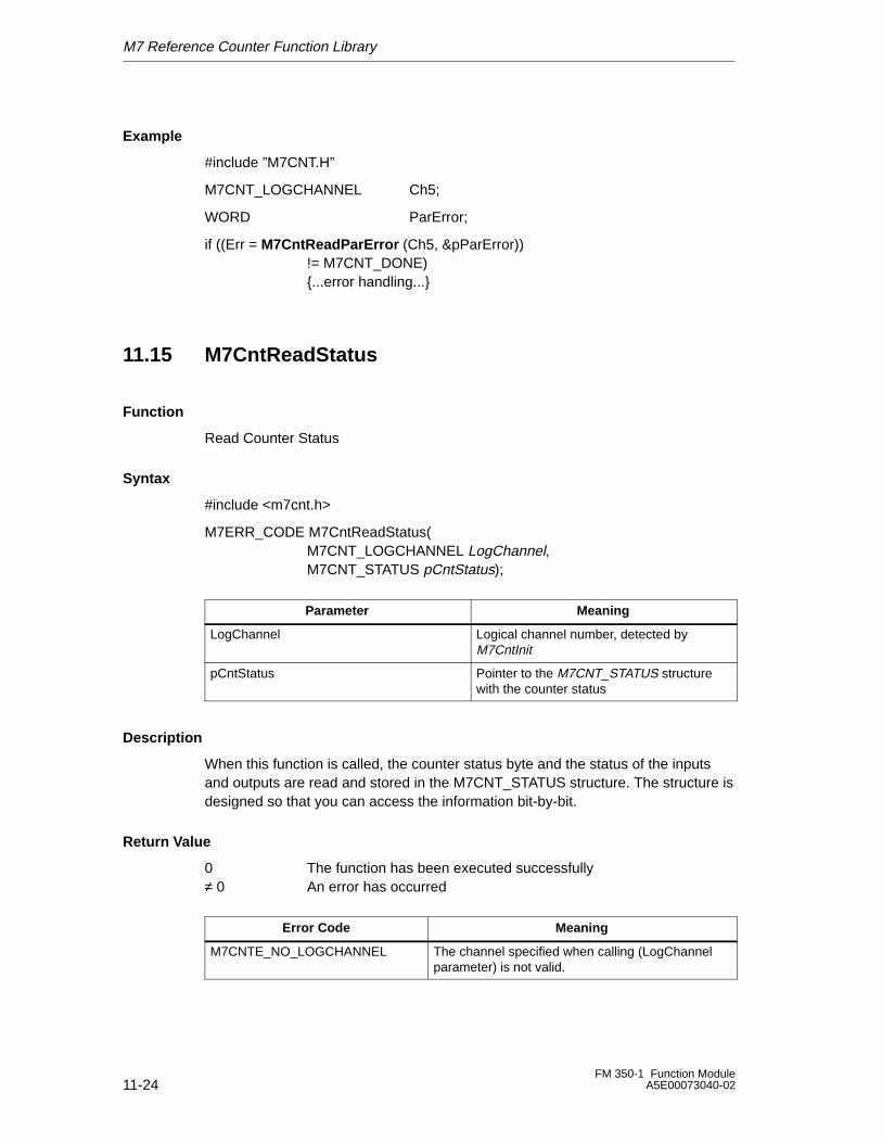
M7 Reference Counter Function Library
11-24FM 350-1 Function Module
A5E00073040-02
Example
#include ”M7CNT.H”
M7CNT_LOGCHANNEL Ch5;
WORD ParError;
if ((Err = M7CntReadParError (Ch5, &pParError)) != M7CNT_DONE){...error handling...}
11.15 M7CntReadStatus
Function
Read Counter Status
Syntax
#include <m7cnt.h>
M7ERR_CODE M7CntReadStatus(M7CNT_LOGCHANNEL LogChannel, M7CNT_STATUS pCntStatus);
ÁÁÁÁÁÁÁÁÁÁÁÁÁÁÁÁÁÁÁÁÁÁÁÁÁÁ
Parameter ÁÁÁÁÁÁÁÁÁÁÁÁÁÁÁÁÁÁÁÁÁÁÁÁÁÁ
Meaning
ÁÁÁÁÁÁÁÁÁÁÁÁÁÁÁÁÁÁÁÁÁÁÁÁÁÁ
LogChannel ÁÁÁÁÁÁÁÁÁÁÁÁÁÁÁÁÁÁÁÁÁÁÁÁÁÁ
Logical channel number, detected byM7CntInitÁÁÁÁÁÁÁÁÁÁÁÁÁ
ÁÁÁÁÁÁÁÁÁÁÁÁÁÁÁÁÁÁÁÁÁÁÁÁÁÁ
pCntStatusÁÁÁÁÁÁÁÁÁÁÁÁÁÁÁÁÁÁÁÁÁÁÁÁÁÁÁÁÁÁÁÁÁÁÁÁÁÁÁ
Pointer to the M7CNT_STATUS structurewith the counter status
Description
When this function is called, the counter status byte and the status of the inputsand outputs are read and stored in the M7CNT_STATUS structure. The structure isdesigned so that you can access the information bit-by-bit.
Return Value
0 The function has been executed successfully≠ 0 An error has occurred
Error Code Meaning
M7CNTE_NO_LOGCHANNEL The channel specified when calling (LogChannelparameter) is not valid.
M7 Reference Counter Function Library
11-25FM 350-1 Function ModuleA5E00073040-02
Example
#include ”M7CNT.H”
M7CNT_LOGCHANNEL Ch5;
if ((Err = M7CntReadStatus (Ch5, &CntStatus)) != M7CNT_DONE){...error handling...}
See Also
Function: M7CntInit, M7CntResetStatus, Structure: M7CNT_STATUS
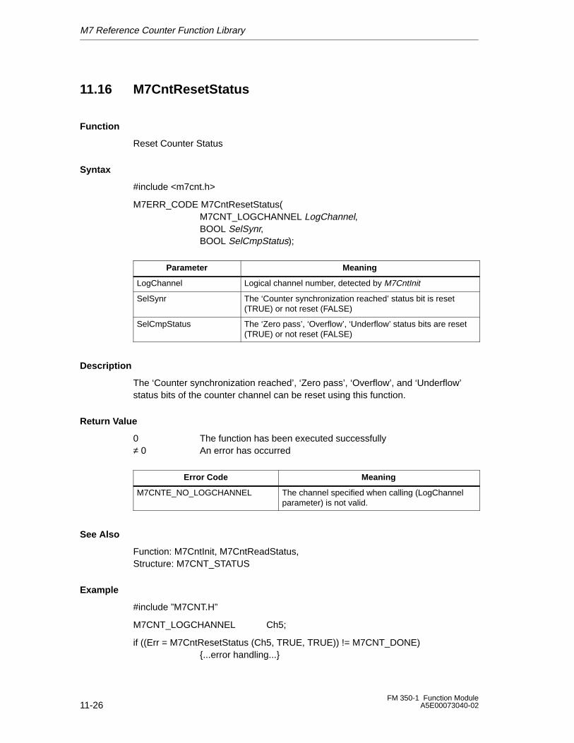
M7 Reference Counter Function Library
11-26FM 350-1 Function Module
A5E00073040-02
11.16 M7CntResetStatus
Function
Reset Counter Status
Syntax
#include <m7cnt.h>
M7ERR_CODE M7CntResetStatus(M7CNT_LOGCHANNEL LogChannel,BOOL SelSynr, BOOL SelCmpStatus);
ÁÁÁÁÁÁÁÁÁÁÁÁÁÁÁÁ
Parameter ÁÁÁÁÁÁÁÁÁÁÁÁÁÁÁÁÁÁÁÁÁÁÁÁÁÁÁÁÁÁÁÁÁÁÁÁ
Meaning
ÁÁÁÁÁÁÁÁÁÁÁÁÁÁÁÁ
LogChannel ÁÁÁÁÁÁÁÁÁÁÁÁÁÁÁÁÁÁÁÁÁÁÁÁÁÁÁÁÁÁÁÁÁÁÁÁ
Logical channel number, detected by M7CntInit
ÁÁÁÁÁÁÁÁÁÁÁÁÁÁÁÁÁÁÁÁÁÁÁÁ
SelSynr ÁÁÁÁÁÁÁÁÁÁÁÁÁÁÁÁÁÁÁÁÁÁÁÁÁÁÁÁÁÁÁÁÁÁÁÁÁÁÁÁÁÁÁÁÁÁÁÁÁÁÁÁÁÁ
The ‘Counter synchronization reached’ status bit is reset(TRUE) or not reset (FALSE)
ÁÁÁÁÁÁÁÁÁÁÁÁÁÁÁÁ
SelCmpStatus ÁÁÁÁÁÁÁÁÁÁÁÁÁÁÁÁÁÁÁÁÁÁÁÁÁÁÁÁÁÁÁÁÁÁÁÁ
The ‘Zero pass’, ‘Overflow’, ‘Underflow’ status bits are reset(TRUE) or not reset (FALSE)
Description
The ‘Counter synchronization reached’, ‘Zero pass’, ‘Overflow’, and ‘Underflow’status bits of the counter channel can be reset using this function.
Return Value
0 The function has been executed successfully≠ 0 An error has occurred
Error Code Meaning
M7CNTE_NO_LOGCHANNEL The channel specified when calling (LogChannelparameter) is not valid.
See Also
Function: M7CntInit, M7CntReadStatus, Structure: M7CNT_STATUS
Example
#include ”M7CNT.H”
M7CNT_LOGCHANNEL Ch5;
if ((Err = M7CntResetStatus (Ch5, TRUE, TRUE)) != M7CNT_DONE){...error handling...}
M7 Reference Counter Function Library
11-27FM 350-1 Function ModuleA5E00073040-02
11.17 M7CntStart
Function
Start Counter Channel - for Operating Modes with Software GateControl
Syntax
#include <m7cnt.h>
M7ERR_CODE M7CntStart(M7CNT_LOGCHANNEL LogChannel);
ÁÁÁÁÁÁÁÁÁÁÁÁÁÁÁÁÁÁÁÁÁÁÁÁÁÁ
ParameterÁÁÁÁÁÁÁÁÁÁÁÁÁÁÁÁÁÁÁÁÁÁÁÁÁÁ
MeaningÁÁÁÁÁÁÁÁÁÁÁÁÁÁÁÁÁÁÁÁÁÁÁÁÁÁÁÁÁÁÁÁÁÁÁÁÁÁÁ
LogChannelÁÁÁÁÁÁÁÁÁÁÁÁÁÁÁÁÁÁÁÁÁÁÁÁÁÁÁÁÁÁÁÁÁÁÁÁÁÁÁ
Logical channel number, detected byM7CntInit
Description
The counter channel is started via the software gate with this function. The functiononly works error-free in the counter modes with software gate control. In the caseof the operating modes with hardware gate control, an operator error is signaled.
Return Value
0 The function has been executed successfully≠ 0 An error has occurred
Error Code Meaning
M7CNTE_NO_LOGCHANNEL The channel specified when calling (Log-Channel parameter) is not valid.
M7CNTE_FS_NO_START Operator error: the counter channel cannotbe started in this operating mode
See Also
Function: M7CntInit, M7CntLoadAndStart
M7 Reference Counter Function Library
11-28FM 350-1 Function Module
A5E00073040-02
Example
#include ”M7CNT.H”
M7CNT_LOGCHANNEL Ch5;
if ((Err = M7CntStart (Ch5)) != M7CNT_DONE){...error handling...}
11.18 M7CntStop
Function
Stop Counter Channel
Syntax
#include <m7cnt.h>
M7ERR_CODE M7CntStop(M7CNT_LOGCHANNEL LogChannel);
ÁÁÁÁÁÁÁÁÁÁÁÁÁÁÁÁÁÁÁÁÁÁÁÁÁÁ
Parameter ÁÁÁÁÁÁÁÁÁÁÁÁÁÁÁÁÁÁÁÁÁÁÁÁÁÁ
MeaningÁÁÁÁÁÁÁÁÁÁÁÁÁÁÁÁÁÁÁÁÁÁÁÁÁÁÁÁÁÁÁÁÁÁÁÁÁÁÁ
LogChannelÁÁÁÁÁÁÁÁÁÁÁÁÁÁÁÁÁÁÁÁÁÁÁÁÁÁÁÁÁÁÁÁÁÁÁÁÁÁÁ
Logical channel number, detected byM7CntInit
Description
The counter channel is stopped with this function. The function is effective in alloperating modes with gate control (hardware and software gate control). In thecontinuous counting without gate control mode, an operator error is signaled. In theoperating modes with software gate control, the counter channel can be restartedwith the M7CntLoadAndStart or M7CntStart functions. The counter channel thenstarts alternative with
• the load value (M7CntStart) already in the load register
• the load value transferred when the M7CntLoadAndStart function was called
Note
When the M7CntStop function is called in the operating modes with hardware gatecontrol, the counter channel cannot be started until the parameters have beenreassigned.
M7 Reference Counter Function Library
11-29FM 350-1 Function ModuleA5E00073040-02
Return Value
0 The function has been executed successfully≠ 0 An error has occurred
Error Code Meaning
M7CNTE_NO_LOGCHANNEL The channel specified when calling (LogChannelparameter) is not valid.
M7CNTE_FS_NO_STOP Operator error: the counter channel cannot bestopped in this operating mode
See Also
Function: M7CntInit, M7CntLoadAndStart, M7CntStart, M7CntStopAndRead
Example
#include ”M7CNT.H”
M7CNT_LOGCHANNEL Ch5;if ((Err = M7CntStop (Ch5)) != M7CNT_DONE)
{...error handling...}
M7 Reference Counter Function Library
11-30FM 350-1 Function Module
A5E00073040-02
11.19 M7CntStopAndRead
Function
Stop Counter Channel and Read Counter Value
Syntax
#include <m7cnt.h>
M7ERR_CODE M7CntStopAndRead(M7CNT_LOGCHANNEL LogChannel, DWORD_PTR pActCntV);
ÁÁÁÁÁÁÁÁÁÁÁÁÁÁÁÁÁÁ
Parameter ÁÁÁÁÁÁÁÁÁÁÁÁÁÁÁÁÁÁÁÁÁÁÁÁÁÁÁÁÁÁÁÁÁÁ
MeaningÁÁÁÁÁÁÁÁÁÁÁÁÁÁÁÁÁÁ
LogChannel ÁÁÁÁÁÁÁÁÁÁÁÁÁÁÁÁÁÁÁÁÁÁÁÁÁÁÁÁÁÁÁÁÁÁ
Logical channel number, detected by M7CntInitÁÁÁÁÁÁÁÁÁÁÁÁÁÁÁÁÁÁ
pActCntV ÁÁÁÁÁÁÁÁÁÁÁÁÁÁÁÁÁÁÁÁÁÁÁÁÁÁÁÁÁÁÁÁÁÁ
Pointer to current counter status
Description
This function stops the counter channel and reads the counter status. The functionis effective in all operating modes with gate control (hardware and software gatecontrol). In the continuous counting without gate control mode, an operator error issignaled. In the operating modes with software gate control, the counter channelcan be restarted with the M7CntLoadAndStart or M7CntStart functions. Thecounter channel then starts alternative with
• the load value (M7CntStart) already in the load register
• the load value transferred when the M7CntLoadAndStart function was called
Note
When the M7CntStopAndRead function is called in the operating modes withhardware gate control, the counter channel cannot be started until the parametershave been reassigned.
Return Value
0 The function has been executed successfully≠ 0 An error has occurred
Error Code Meaning
M7CNTE_NO_LOGCHANNEL The channel specified when calling (LogChannelparameter) is not valid.
M7CNTE_FS_NO_STOP Operator error: the counter channel cannot bestoped in this operating mode.
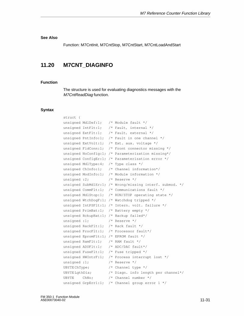
M7 Reference Counter Function Library
11-31FM 350-1 Function ModuleA5E00073040-02
See Also
Function: M7CntInit, M7CntStop, M7CntStart, M7CntLoadAndStart
11.20 M7CNT_DIAGINFO
Function
The structure is used for evaluating diagnostics messages with theM7CntReadDiag function.
Syntax
struct {
unsigned MdlDef:1; /* Module fault */
unsigned IntFlt:1; /* Fault, internal */
unsigned ExtFlt:1; /* Fault, external */
unsigned PntInfo:1; /* Fault in one channel */
unsigned ExtVolt:1; /* Ext. aux. voltage */
unsigned FldConn:1; /* Front connector missing */
unsigned NoConfig:1; /* Parameterization missing*/
unsigned ConfigEr:1; /* Parameterization error */
unsigned MdlType:4; /* Type class */
unsigned ChInfo:1; /* Channel information*/
unsigned ModInfo:1; /* Module information */
unsigned :2; /* Reserve */
unsigned SubMdlEr:1; /* Wrong/missing interf. submod. */
unsigned CommFlt:1; /* Communications fault */
unsigned MdlStop:1; /* RUN/STOP operating state */
unsigned WtchDogF:1; /* Watchdog tripped */
unsigned IntPSFlt:1; /* Intern. volt. failure */
unsigned PrimBat:1; /* Battery empty */
unsigned BckupBat:1; /* Backup failed*/
unsigned :1; /* Reserve */
unsigned RackFlt:1; /* Rack fault */
unsigned ProcFlt:1; /* Processor fault*/
unsigned EpromFlt:1; /* EPROM fault */
unsigned RamFlt:1; /* RAM fault */
unsigned ADUFlt:1; /* ADC/DAC fault*/
unsigned FuseFlt:1; /* Fuse tripped */
unsigned HWIntrF:1; /* Process interrupt lost */
unsigned :1; /* Reserve */
UBYTE ChType; /* Channel type */
UBYTE LgthDia; /* Diagn. info length per channel*/
UBYTE ChNo; /* Channel number */
unsigned GrpErr1:1; /* Channel group error 1 */
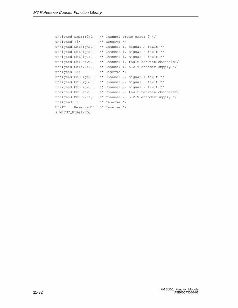
M7 Reference Counter Function Library
11-32FM 350-1 Function Module
A5E00073040-02
unsigned GrpErr2:1; /* Channel group error 2 */
unsigned :6; /* Reserve */
unsigned Ch1SigA:1; /* Channel 1, signal A fault */
unsigned Ch1SigB:1; /* Channel 1, signal B fault */
unsigned Ch1SigZ:1; /* Channel 1, signal N fault */
unsigned Ch1Betw:1; /* Channel 1, fault between channels*/
unsigned Ch15V2:1; /* Channel 1, 5.2 V encoder supply */
unsigned :3; /* Reserve */
unsigned Ch2SigA:1; /* Channel 2, signal A fault */
unsigned Ch2SigB:1; /* Channel 2, signal B fault */
unsigned Ch2SigZ:1; /* Channel 2, signal N fault */
unsigned Ch2Betw:1; /* Channel 2, fault between channels*/
unsigned Ch25V2:1; /* Channel 2, 5.2-V encoder supply */
unsigned :3; /* Reserve */
UBYTE Reserved11; /* Reserve */
} M7CNT_DIAGINFO;
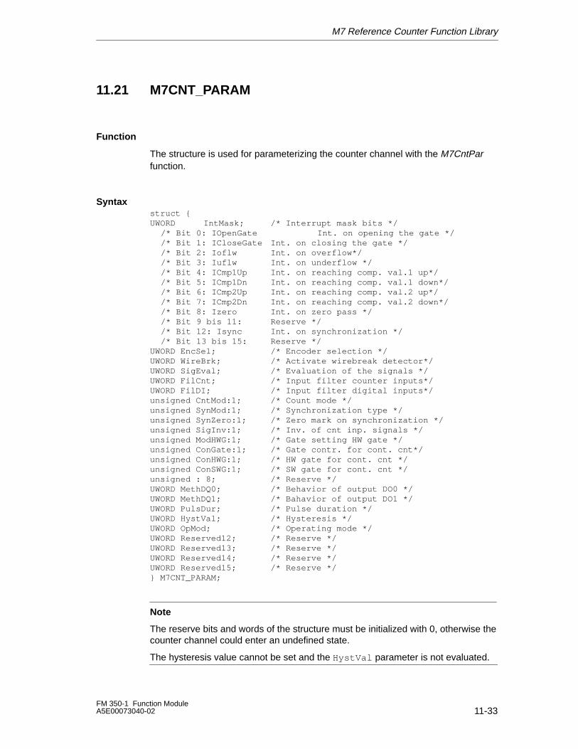
M7 Reference Counter Function Library
11-33FM 350-1 Function ModuleA5E00073040-02
11.21 M7CNT_PARAM
Function
The structure is used for parameterizing the counter channel with the M7CntParfunction.
Syntaxstruct {UWORD IntMask; /* Interrupt mask bits */
/* Bit 0: IOpenGate Int. on opening the gate *//* Bit 1: ICloseGate Int. on closing the gate *//* Bit 2: Ioflw Int. on overflow*//* Bit 3: Iuflw Int. on underflow *//* Bit 4: ICmp1Up Int. on reaching comp. val.1 up*//* Bit 5: ICmp1Dn Int. on reaching comp. val.1 down*//* Bit 6: ICmp2Up Int. on reaching comp. val.2 up*//* Bit 7: ICmp2Dn Int. on reaching comp. val.2 down*//* Bit 8: Izero Int. on zero pass *//* Bit 9 bis 11: Reserve *//* Bit 12: Isync Int. on synchronization *//* Bit 13 bis 15: Reserve */
UWORD EncSel; /* Encoder selection */UWORD WireBrk; /* Activate wirebreak detector*/UWORD SigEval; /* Evaluation of the signals */UWORD FilCnt; /* Input filter counter inputs*/UWORD FilDI; /* Input filter digital inputs*/unsigned CntMod:1; /* Count mode */unsigned SynMod:1; /* Synchronization type */unsigned SynZero:1; /* Zero mark on synchronization */unsigned SigInv:1; /* Inv. of cnt inp. signals */unsigned ModHWG:1; /* Gate setting HW gate */unsigned ConGate:1; /* Gate contr. for cont. cnt*/unsigned ConHWG:1; /* HW gate for cont. cnt */unsigned ConSWG:1; /* SW gate for cont. cnt */unsigned : 8; /* Reserve */UWORD MethDQ0; /* Behavior of output DO0 */UWORD MethDQ1; /* Bahavior of output DO1 */UWORD PulsDur; /* Pulse duration */UWORD HystVal; /* Hysteresis */UWORD OpMod; /* Operating mode */UWORD Reserved12; /* Reserve */UWORD Reserved13; /* Reserve */UWORD Reserved14; /* Reserve */UWORD Reserved15; /* Reserve */} M7CNT_PARAM;
Note
The reserve bits and words of the structure must be initialized with 0, otherwise thecounter channel could enter an undefined state.
The hysteresis value cannot be set and the HystVal parameter is not evaluated.
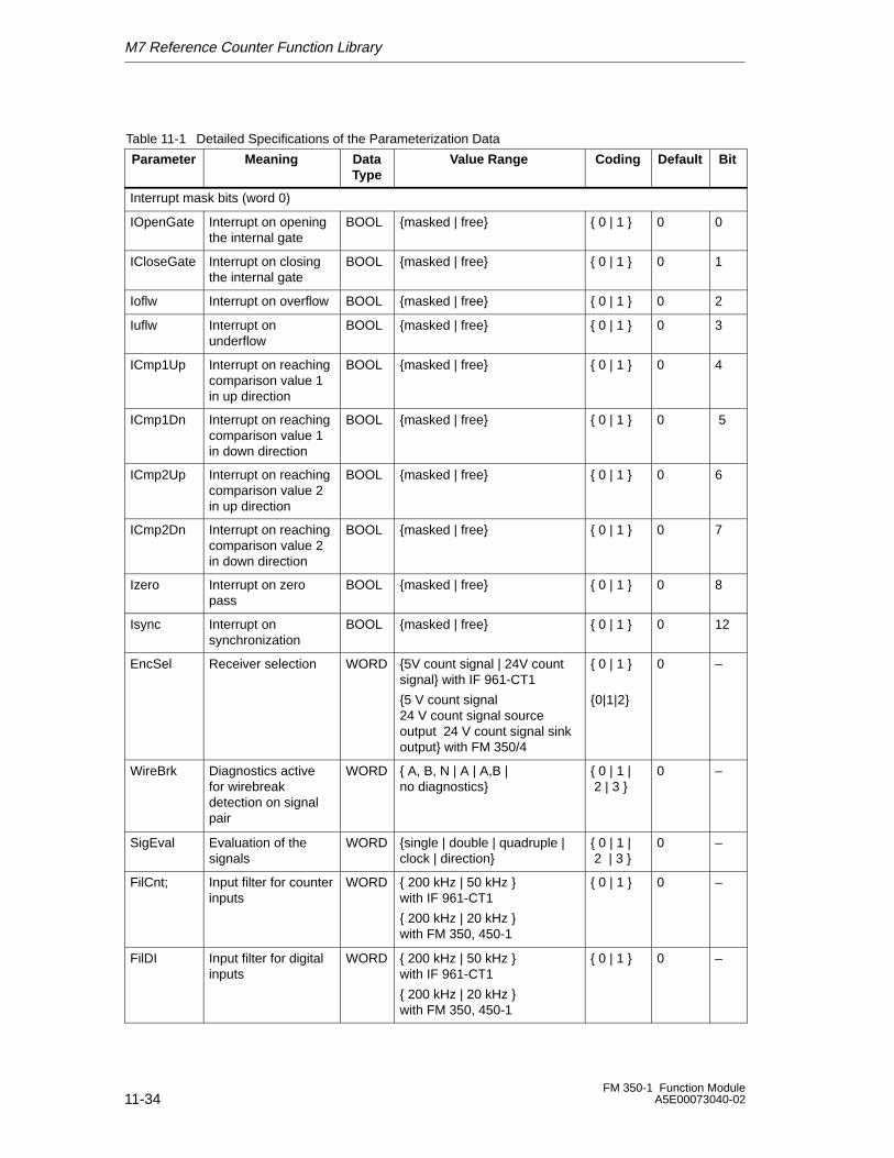
M7 Reference Counter Function Library
11-34FM 350-1 Function Module
A5E00073040-02
Table 11-1 Detailed Specifications of the Parameterization Data ÁÁÁÁÁÁÁÁÁÁÁÁÁÁÁ
Parameter ÁÁÁÁÁÁÁÁÁÁÁÁÁÁÁÁÁÁÁÁÁ
Meaning ÁÁÁÁÁÁÁÁÁ
DataType
ÁÁÁÁÁÁÁÁÁÁÁÁÁÁÁÁÁÁÁÁÁÁÁÁÁÁÁÁÁÁ
Value Range ÁÁÁÁÁÁÁÁÁ
CodingÁÁÁÁÁÁÁÁÁÁÁÁ
DefaultÁÁÁÁÁÁÁÁÁ
Bit
Interrupt mask bits (word 0)
ÁÁÁÁÁÁÁÁÁÁÁÁÁÁÁ
IOpenGate ÁÁÁÁÁÁÁÁÁÁÁÁÁÁÁÁÁÁÁÁÁ
Interrupt on openingthe internal gate
ÁÁÁÁÁÁÁÁÁ
BOOLÁÁÁÁÁÁÁÁÁÁÁÁÁÁÁÁÁÁÁÁÁÁÁÁÁÁÁÁÁÁ
{masked | free} ÁÁÁÁÁÁÁÁÁ
{ 0 | 1 }ÁÁÁÁÁÁÁÁÁÁÁÁ
0 ÁÁÁÁÁÁÁÁÁ
0
ÁÁÁÁÁÁÁÁÁÁ
ICloseGateÁÁÁÁÁÁÁÁÁÁÁÁÁÁInterrupt on closingthe internal gate
ÁÁÁÁÁÁ
BOOLÁÁÁÁÁÁÁÁÁÁÁÁÁÁÁÁÁÁÁÁ
{masked | free} ÁÁÁÁÁÁ{ 0 | 1 }ÁÁÁÁÁÁÁÁ
0 ÁÁÁÁÁÁ
1
ÁÁÁÁÁÁÁÁÁÁÁÁÁÁÁ
IoflwÁÁÁÁÁÁÁÁÁÁÁÁÁÁÁÁÁÁÁÁÁ
Interrupt on overflowÁÁÁÁÁÁÁÁÁ
BOOLÁÁÁÁÁÁÁÁÁÁÁÁÁÁÁÁÁÁÁÁÁÁÁÁÁÁÁÁÁÁ
{masked | free}ÁÁÁÁÁÁÁÁÁ
{ 0 | 1 }ÁÁÁÁÁÁÁÁÁÁÁÁ
0ÁÁÁÁÁÁÁÁÁ
2
ÁÁÁÁÁÁÁÁÁÁ
Iuflw ÁÁÁÁÁÁÁÁÁÁÁÁÁÁ
Interrupt onunderflow
ÁÁÁÁÁÁ
BOOLÁÁÁÁÁÁÁÁÁÁÁÁÁÁÁÁÁÁÁÁ
{masked | free} ÁÁÁÁÁÁ
{ 0 | 1 }ÁÁÁÁÁÁÁÁ
0 ÁÁÁÁÁÁ
3
ÁÁÁÁÁÁÁÁÁÁÁÁÁÁÁÁÁÁÁÁ
ICmp1UpÁÁÁÁÁÁÁÁÁÁÁÁÁÁÁÁÁÁÁÁÁÁÁÁÁÁÁÁ
Interrupt on reachingcomparison value 1in up direction
ÁÁÁÁÁÁÁÁÁÁÁÁ
BOOLÁÁÁÁÁÁÁÁÁÁÁÁÁÁÁÁÁÁÁÁÁÁÁÁÁÁÁÁÁÁÁÁÁÁÁÁÁÁÁÁ
{masked | free}ÁÁÁÁÁÁÁÁÁÁÁÁ
{ 0 | 1 }ÁÁÁÁÁÁÁÁÁÁÁÁÁÁÁÁ
0ÁÁÁÁÁÁÁÁÁÁÁÁ
4
ÁÁÁÁÁÁÁÁÁÁÁÁÁÁÁ
ICmp1Dn ÁÁÁÁÁÁÁÁÁÁÁÁÁÁÁÁÁÁÁÁÁ
Interrupt on reachingcomparison value 1in down direction
ÁÁÁÁÁÁÁÁÁ
BOOLÁÁÁÁÁÁÁÁÁÁÁÁÁÁÁÁÁÁÁÁÁÁÁÁÁÁÁÁÁÁ
{masked | free} ÁÁÁÁÁÁÁÁÁ
{ 0 | 1 }ÁÁÁÁÁÁÁÁÁÁÁÁ
0 ÁÁÁÁÁÁÁÁÁ
5
ÁÁÁÁÁÁÁÁÁÁÁÁÁÁÁÁÁÁÁÁ
ICmp2UpÁÁÁÁÁÁÁÁÁÁÁÁÁÁÁÁÁÁÁÁÁÁÁÁÁÁÁÁ
Interrupt on reachingcomparison value 2in up direction
ÁÁÁÁÁÁÁÁÁÁÁÁ
BOOLÁÁÁÁÁÁÁÁÁÁÁÁÁÁÁÁÁÁÁÁÁÁÁÁÁÁÁÁÁÁÁÁÁÁÁÁÁÁÁÁ
{masked | free}ÁÁÁÁÁÁÁÁÁÁÁÁ
{ 0 | 1 }ÁÁÁÁÁÁÁÁÁÁÁÁÁÁÁÁ
0ÁÁÁÁÁÁÁÁÁÁÁÁ
6
ÁÁÁÁÁÁÁÁÁÁÁÁÁÁÁ
ICmp2Dn ÁÁÁÁÁÁÁÁÁÁÁÁÁÁÁÁÁÁÁÁÁ
Interrupt on reachingcomparison value 2in down direction
ÁÁÁÁÁÁÁÁÁ
BOOLÁÁÁÁÁÁÁÁÁÁÁÁÁÁÁÁÁÁÁÁÁÁÁÁÁÁÁÁÁÁ
{masked | free} ÁÁÁÁÁÁÁÁÁ
{ 0 | 1 }ÁÁÁÁÁÁÁÁÁÁÁÁ
0 ÁÁÁÁÁÁÁÁÁ
7
ÁÁÁÁÁÁÁÁÁÁÁÁÁÁÁ
Izero ÁÁÁÁÁÁÁÁÁÁÁÁÁÁÁÁÁÁÁÁÁ
Interrupt on zeropass
ÁÁÁÁÁÁÁÁÁ
BOOLÁÁÁÁÁÁÁÁÁÁÁÁÁÁÁÁÁÁÁÁÁÁÁÁÁÁÁÁÁÁ
{masked | free} ÁÁÁÁÁÁÁÁÁ
{ 0 | 1 }ÁÁÁÁÁÁÁÁÁÁÁÁ
0 ÁÁÁÁÁÁÁÁÁ
8
ÁÁÁÁÁÁÁÁÁÁÁÁÁÁÁ
Isync ÁÁÁÁÁÁÁÁÁÁÁÁÁÁÁÁÁÁÁÁÁ
Interrupt onsynchronization
ÁÁÁÁÁÁÁÁÁ
BOOLÁÁÁÁÁÁÁÁÁÁÁÁÁÁÁÁÁÁÁÁÁÁÁÁÁÁÁÁÁÁ
{masked | free} ÁÁÁÁÁÁÁÁÁ
{ 0 | 1 }ÁÁÁÁÁÁÁÁÁÁÁÁ
0 ÁÁÁÁÁÁÁÁÁ
12
ÁÁÁÁÁÁÁÁÁÁÁÁÁÁÁÁÁÁÁÁÁÁÁÁÁ
EncSel ÁÁÁÁÁÁÁÁÁÁÁÁÁÁÁÁÁÁÁÁÁÁÁÁÁÁÁÁÁÁÁÁÁÁÁ
Receiver selection ÁÁÁÁÁÁÁÁÁÁÁÁÁÁÁ
WORDÁÁÁÁÁÁÁÁÁÁÁÁÁÁÁÁÁÁÁÁÁÁÁÁÁÁÁÁÁÁÁÁÁÁÁÁÁÁÁÁÁÁÁÁÁÁÁÁÁÁ
{5V count signal | 24V countsignal} with IF 961-CT1
{5 V count signal24 V count signal sourceoutput 24 V count signal sinkoutput} with FM 350/4
ÁÁÁÁÁÁÁÁÁÁÁÁÁÁÁ
{ 0 | 1 }
{0|1|2}
ÁÁÁÁÁÁÁÁÁÁÁÁÁÁÁÁÁÁÁÁ
0 ÁÁÁÁÁÁÁÁÁÁÁÁÁÁÁ
–
ÁÁÁÁÁÁÁÁÁÁÁÁÁÁÁÁÁÁÁÁÁÁÁÁÁ
WireBrkÁÁÁÁÁÁÁÁÁÁÁÁÁÁÁÁÁÁÁÁÁÁÁÁÁÁÁÁÁÁÁÁÁÁÁ
Diagnostics activefor wirebreakdetection on signalpair
ÁÁÁÁÁÁÁÁÁÁÁÁÁÁÁ
WORDÁÁÁÁÁÁÁÁÁÁÁÁÁÁÁÁÁÁÁÁÁÁÁÁÁÁÁÁÁÁÁÁÁÁÁÁÁÁÁÁÁÁÁÁÁÁÁÁÁÁ
{ A, B, N | A | A,B |no diagnostics}
ÁÁÁÁÁÁÁÁÁÁÁÁÁÁÁ
{ 0 | 1 | 2 | 3 }
ÁÁÁÁÁÁÁÁÁÁÁÁÁÁÁÁÁÁÁÁ
0ÁÁÁÁÁÁÁÁÁÁÁÁÁÁÁ
–
ÁÁÁÁÁÁÁÁÁÁ
SigEval ÁÁÁÁÁÁÁÁÁÁÁÁÁÁ
Evaluation of thesignals
ÁÁÁÁÁÁ
WORDÁÁÁÁÁÁÁÁÁÁÁÁÁÁÁÁÁÁÁÁ
{single | double | quadruple |clock | direction}
ÁÁÁÁÁÁ
{ 0 | 1 | 2 | 3 }ÁÁÁÁÁÁÁÁ
0 ÁÁÁÁÁÁ
–
ÁÁÁÁÁÁÁÁÁÁÁÁÁÁÁÁÁÁÁÁÁÁÁÁÁ
FilCnt;ÁÁÁÁÁÁÁÁÁÁÁÁÁÁÁÁÁÁÁÁÁÁÁÁÁÁÁÁÁÁÁÁÁÁÁ
Input filter for counterinputs
ÁÁÁÁÁÁÁÁÁÁÁÁÁÁÁ
WORDÁÁÁÁÁÁÁÁÁÁÁÁÁÁÁÁÁÁÁÁÁÁÁÁÁÁÁÁÁÁÁÁÁÁÁÁÁÁÁÁÁÁÁÁÁÁÁÁÁÁ
{ 200 kHz | 50 kHz } with IF 961-CT1
{ 200 kHz | 20 kHz } with FM 350, 450-1
ÁÁÁÁÁÁÁÁÁÁÁÁÁÁÁ
{ 0 | 1 }ÁÁÁÁÁÁÁÁÁÁÁÁÁÁÁÁÁÁÁÁ
0ÁÁÁÁÁÁÁÁÁÁÁÁÁÁÁ
–
ÁÁÁÁÁÁÁÁÁÁÁÁÁÁÁÁÁÁÁÁ
FilDI ÁÁÁÁÁÁÁÁÁÁÁÁÁÁÁÁÁÁÁÁÁÁÁÁÁÁÁÁ
Input filter for digitalinputs
ÁÁÁÁÁÁÁÁÁÁÁÁ
WORDÁÁÁÁÁÁÁÁÁÁÁÁÁÁÁÁÁÁÁÁÁÁÁÁÁÁÁÁÁÁÁÁÁÁÁÁÁÁÁÁ
{ 200 kHz | 50 kHz } with IF 961-CT1
{ 200 kHz | 20 kHz } with FM 350, 450-1
ÁÁÁÁÁÁÁÁÁÁÁÁ
{ 0 | 1 }ÁÁÁÁÁÁÁÁÁÁÁÁÁÁÁÁ
0 ÁÁÁÁÁÁÁÁÁÁÁÁ
–
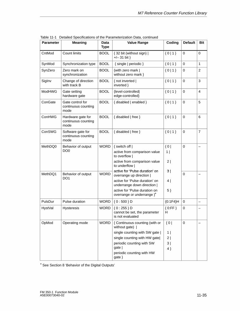
M7 Reference Counter Function Library
11-35FM 350-1 Function ModuleA5E00073040-02
Table 11-1 Detailed Specifications of the Parameterization Data, continuedÁÁÁÁÁÁÁÁÁ
BitÁÁÁÁÁÁÁÁÁ
DefaultÁÁÁÁÁÁÁÁÁÁÁÁ
CodingÁÁÁÁÁÁÁÁÁÁÁÁÁÁÁÁÁÁÁÁÁÁÁÁÁÁÁÁÁÁ
Value RangeÁÁÁÁÁÁÁÁÁ
DataType
ÁÁÁÁÁÁÁÁÁÁÁÁÁÁÁÁÁÁÁÁÁ
MeaningÁÁÁÁÁÁÁÁÁÁÁÁÁÁÁ
Parameter
ÁÁÁÁÁÁÁÁÁÁÁÁÁÁÁ
CntMod ÁÁÁÁÁÁÁÁÁÁÁÁÁÁÁÁÁÁÁÁÁ
Count limits ÁÁÁÁÁÁÁÁÁ
BOOLÁÁÁÁÁÁÁÁÁÁÁÁÁÁÁÁÁÁÁÁÁÁÁÁÁÁÁÁÁÁ
{ 32 bit (without sign) | +/– 31 bit }
ÁÁÁÁÁÁÁÁÁÁÁÁ
{ 0 | 1 } ÁÁÁÁÁÁÁÁÁ
0 ÁÁÁÁÁÁÁÁÁ
0
ÁÁÁÁÁÁÁÁÁÁ
SynMod ÁÁÁÁÁÁÁÁÁÁÁÁÁÁ
Synchronization typeÁÁÁÁÁÁ
BOOLÁÁÁÁÁÁÁÁÁÁÁÁÁÁÁÁÁÁÁÁ
{ single | periodic } ÁÁÁÁÁÁÁÁ
{ 0 | 1 } ÁÁÁÁÁÁ0 ÁÁÁÁÁÁ
1
ÁÁÁÁÁÁÁÁÁÁ
SynZero ÁÁÁÁÁÁÁÁÁÁÁÁÁÁ
Zero mark onsynchronization
ÁÁÁÁÁÁ
BOOLÁÁÁÁÁÁÁÁÁÁÁÁÁÁÁÁÁÁÁÁ
{with zero mark | without zero mark }
ÁÁÁÁÁÁÁÁ
{ 0 | 1 } ÁÁÁÁÁÁ0 ÁÁÁÁÁÁ
2
ÁÁÁÁÁÁÁÁÁÁÁÁÁÁÁ
SigInvÁÁÁÁÁÁÁÁÁÁÁÁÁÁÁÁÁÁÁÁÁ
Change of directionwith track B
ÁÁÁÁÁÁÁÁÁ
BOOLÁÁÁÁÁÁÁÁÁÁÁÁÁÁÁÁÁÁÁÁÁÁÁÁÁÁÁÁÁÁ
{ not inverted | inverted }
ÁÁÁÁÁÁÁÁÁÁÁÁ
{ 0 | 1 }ÁÁÁÁÁÁÁÁÁ
0ÁÁÁÁÁÁÁÁÁ
3
ÁÁÁÁÁÁÁÁÁÁÁÁÁÁÁ
ModHWGÁÁÁÁÁÁÁÁÁÁÁÁÁÁÁÁÁÁÁÁÁ
Gate settinghardware gate
ÁÁÁÁÁÁÁÁÁ
BOOLÁÁÁÁÁÁÁÁÁÁÁÁÁÁÁÁÁÁÁÁÁÁÁÁÁÁÁÁÁÁ
{level-controlled| edge-controlled}
ÁÁÁÁÁÁÁÁÁÁÁÁ
{ 0 | 1 }ÁÁÁÁÁÁÁÁÁ
0ÁÁÁÁÁÁÁÁÁ
4
ÁÁÁÁÁÁÁÁÁÁÁÁÁÁÁ
ConGate ÁÁÁÁÁÁÁÁÁÁÁÁÁÁÁÁÁÁÁÁÁ
Gate control forcontinuous countingmode
ÁÁÁÁÁÁÁÁÁ
BOOLÁÁÁÁÁÁÁÁÁÁÁÁÁÁÁÁÁÁÁÁÁÁÁÁÁÁÁÁÁÁ
{ disabled | enabled } ÁÁÁÁÁÁÁÁÁÁÁÁ
{ 0 | 1 } ÁÁÁÁÁÁÁÁÁ
0 ÁÁÁÁÁÁÁÁÁ
5
ÁÁÁÁÁÁÁÁÁÁÁÁÁÁÁÁÁÁÁÁ
ConHWGÁÁÁÁÁÁÁÁÁÁÁÁÁÁÁÁÁÁÁÁÁÁÁÁÁÁÁÁ
Hardware gate forcontinuous countingmode
ÁÁÁÁÁÁÁÁÁÁÁÁ
BOOLÁÁÁÁÁÁÁÁÁÁÁÁÁÁÁÁÁÁÁÁÁÁÁÁÁÁÁÁÁÁÁÁÁÁÁÁÁÁÁÁ
{ disabled | free }ÁÁÁÁÁÁÁÁÁÁÁÁÁÁÁÁ
{ 0 | 1 }ÁÁÁÁÁÁÁÁÁÁÁÁ
0ÁÁÁÁÁÁÁÁÁÁÁÁ
6
ÁÁÁÁÁÁÁÁÁÁÁÁÁÁÁ
ConSWG ÁÁÁÁÁÁÁÁÁÁÁÁÁÁÁÁÁÁÁÁÁ
Software gate forcontinuous countingmode
ÁÁÁÁÁÁÁÁÁ
BOOLÁÁÁÁÁÁÁÁÁÁÁÁÁÁÁÁÁÁÁÁÁÁÁÁÁÁÁÁÁÁ
{ disabled | free } ÁÁÁÁÁÁÁÁÁÁÁÁ
{ 0 | 1 } ÁÁÁÁÁÁÁÁÁ
0 ÁÁÁÁÁÁÁÁÁ
7
ÁÁÁÁÁÁÁÁÁÁÁÁÁÁÁÁÁÁÁÁÁÁÁÁÁÁÁÁÁÁ
MethDQ0ÁÁÁÁÁÁÁÁÁÁÁÁÁÁÁÁÁÁÁÁÁÁÁÁÁÁÁÁÁÁÁÁÁÁÁÁÁÁÁÁÁÁ
Behavior of outputDO0
ÁÁÁÁÁÁÁÁÁÁÁÁÁÁÁÁÁÁ
WORDÁÁÁÁÁÁÁÁÁÁÁÁÁÁÁÁÁÁÁÁÁÁÁÁÁÁÁÁÁÁÁÁÁÁÁÁÁÁÁÁÁÁÁÁÁÁÁÁÁÁÁÁÁÁÁÁÁÁÁÁ
{ switch off |
active from comparison valueto overflow |
active from comparison valueto underflow |
active for ‘Pulse duration’ on
ÁÁÁÁÁÁÁÁÁÁÁÁÁÁÁÁÁÁÁÁÁÁÁÁ
{ 0 |
1 |
2 |
3 |
ÁÁÁÁÁÁÁÁÁÁÁÁÁÁÁÁÁÁ
0ÁÁÁÁÁÁÁÁÁÁÁÁÁÁÁÁÁÁ
–
ÁÁÁÁÁÁÁÁÁÁÁÁÁÁÁÁÁÁÁÁÁÁÁÁÁ
MethDQ1 ÁÁÁÁÁÁÁÁÁÁÁÁÁÁÁÁÁÁÁÁÁÁÁÁÁÁÁÁÁÁÁÁÁÁÁ
Behavior of outputDO1
ÁÁÁÁÁÁÁÁÁÁÁÁÁÁÁ
WORDÁÁÁÁÁÁÁÁÁÁÁÁÁÁÁÁÁÁÁÁÁÁÁÁÁÁÁÁÁÁÁÁÁÁÁÁÁÁÁÁÁÁÁÁÁÁÁÁÁÁ
active for ‘Pulse duration’ onoverrange up direction |
active for ‘Pulse duration’ onunderrange down direction |
active for ‘Pulse duration onoverrange or underrange }*
ÁÁÁÁÁÁÁÁÁÁÁÁÁÁÁÁÁÁÁÁ
3 |
4 |
5 }
ÁÁÁÁÁÁÁÁÁÁÁÁÁÁÁ
0 ÁÁÁÁÁÁÁÁÁÁÁÁÁÁÁ
–
ÁÁÁÁÁÁÁÁÁÁÁÁÁÁÁ
PulsDurÁÁÁÁÁÁÁÁÁÁÁÁÁÁÁÁÁÁÁÁÁ
Pulse durationÁÁÁÁÁÁÁÁÁ
WORDÁÁÁÁÁÁÁÁÁÁÁÁÁÁÁÁÁÁÁÁÁÁÁÁÁÁÁÁÁÁ
{ 0 : 500 } DÁÁÁÁÁÁÁÁÁÁÁÁ
{0:1F4}HÁÁÁÁÁÁÁÁÁ
0ÁÁÁÁÁÁÁÁÁ
–
ÁÁÁÁÁÁÁÁÁÁÁÁÁÁÁ
HystVal ÁÁÁÁÁÁÁÁÁÁÁÁÁÁÁÁÁÁÁÁÁ
Hysteresis ÁÁÁÁÁÁÁÁÁ
WORDÁÁÁÁÁÁÁÁÁÁÁÁÁÁÁÁÁÁÁÁÁÁÁÁÁÁÁÁÁÁ
{ 0 : 255 } Dcannot be set, the parameteris not evaluated
ÁÁÁÁÁÁÁÁÁÁÁÁ
{ 0:FF }H
ÁÁÁÁÁÁÁÁÁ
0 ÁÁÁÁÁÁÁÁÁ
–
ÁÁÁÁÁÁÁÁÁÁÁÁÁÁÁÁÁÁÁÁÁÁÁÁÁÁÁÁÁÁÁÁÁÁÁÁÁÁÁÁ
OpMod ÁÁÁÁÁÁÁÁÁÁÁÁÁÁÁÁÁÁÁÁÁÁÁÁÁÁÁÁÁÁÁÁÁÁÁÁÁÁÁÁÁÁÁÁÁÁÁÁÁÁÁÁÁÁÁÁ
Operating mode ÁÁÁÁÁÁÁÁÁÁÁÁÁÁÁÁÁÁÁÁÁÁÁÁ
WORDÁÁÁÁÁÁÁÁÁÁÁÁÁÁÁÁÁÁÁÁÁÁÁÁÁÁÁÁÁÁÁÁÁÁÁÁÁÁÁÁÁÁÁÁÁÁÁÁÁÁÁÁÁÁÁÁÁÁÁÁÁÁÁÁÁÁÁÁÁÁÁÁÁÁÁÁÁÁÁÁ
{ Continuous counting (with orwithout gate) |
single counting with SW gate |
single counting with HW gate|
periodic counting with SWgate |
periodic counting with HWgate }
ÁÁÁÁÁÁÁÁÁÁÁÁÁÁÁÁÁÁÁÁÁÁÁÁÁÁÁÁÁÁÁÁ
{ 0 |
1 |
2 |
3 |
4 }
ÁÁÁÁÁÁÁÁÁÁÁÁÁÁÁÁÁÁÁÁÁÁÁÁ
0 ÁÁÁÁÁÁÁÁÁÁÁÁÁÁÁÁÁÁÁÁÁÁÁÁ
–
* See Section 8 ‘Behavior of the Digital Outputs’
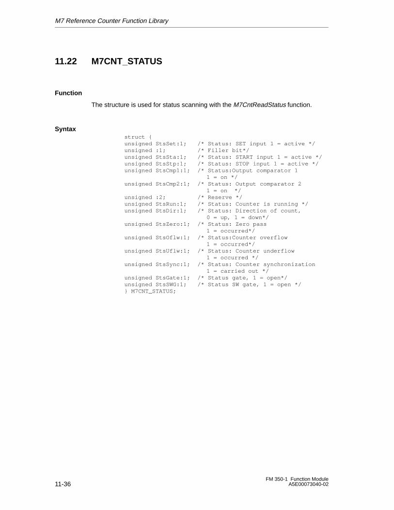
M7 Reference Counter Function Library
11-36FM 350-1 Function Module
A5E00073040-02
11.22 M7CNT_STATUS
Function
The structure is used for status scanning with the M7CntReadStatus function.
Syntaxstruct {unsigned StsSet:1; /* Status: SET input 1 = active */unsigned :1; /* Filler bit*/unsigned StsSta:1; /* Status: START input 1 = active */unsigned StsStp:1; /* Status: STOP input 1 = active */unsigned StsCmp1:1; /* Status:Output comparator 1
1 = on */unsigned StsCmp2:1; /* Status: Output comparator 2
1 = on */unsigned :2; /* Reserve */unsigned StsRun:1; /* Status: Counter is running */unsigned StsDir:1; /* Status: Direction of count,
0 = up, 1 = down*/unsigned StsZero:1; /* Status: Zero pass
1 = occurred*/unsigned StsOflw:1; /* Status:Counter overflow
1 = occurred*/unsigned StsUflw:1; /* Status: Counter underflow
1 = occurred */unsigned StsSync:1; /* Status: Counter synchronization
1 = carried out */unsigned StsGate:1; /* Status gate, 1 = open*/unsigned StsSWG:1; /* Status SW gate, 1 = open */} M7CNT_STATUS;
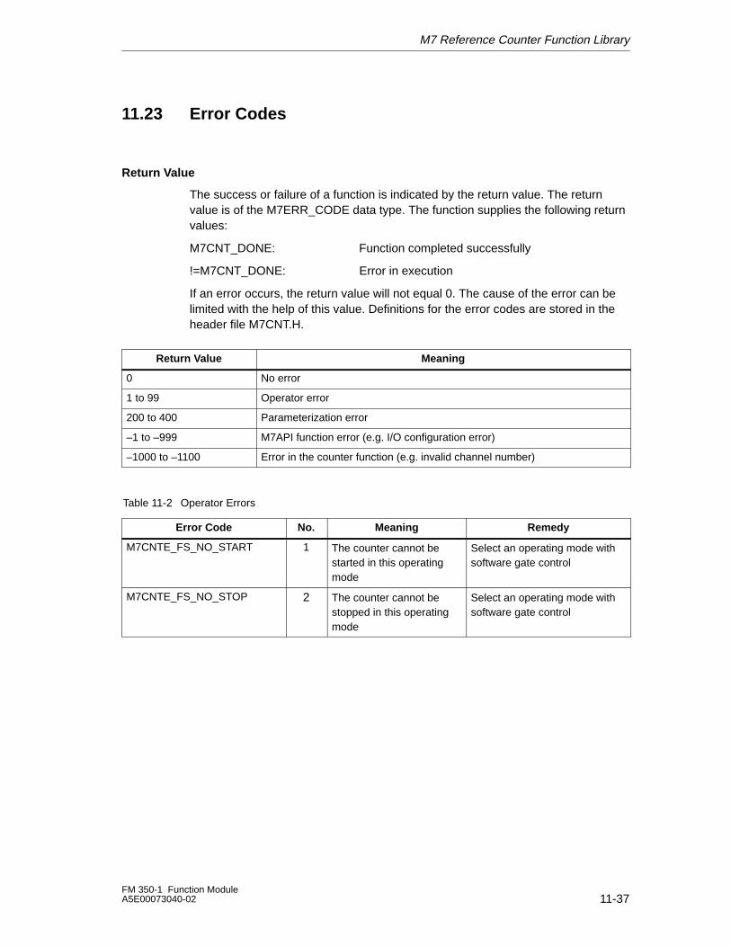
M7 Reference Counter Function Library
11-37FM 350-1 Function ModuleA5E00073040-02
11.23 Error Codes
Return Value
The success or failure of a function is indicated by the return value. The returnvalue is of the M7ERR_CODE data type. The function supplies the following returnvalues:
M7CNT_DONE: Function completed successfully
!=M7CNT_DONE: Error in execution
If an error occurs, the return value will not equal 0. The cause of the error can belimited with the help of this value. Definitions for the error codes are stored in theheader file M7CNT.H.
ÁÁÁÁÁÁÁÁÁÁÁÁÁÁÁÁ
Return Value ÁÁÁÁÁÁÁÁÁÁÁÁÁÁÁÁÁÁÁÁÁÁÁÁÁÁÁÁÁÁÁÁÁÁÁÁÁÁÁÁÁÁÁÁ
Meaning
ÁÁÁÁÁÁÁÁÁÁÁÁÁÁÁÁ
0 ÁÁÁÁÁÁÁÁÁÁÁÁÁÁÁÁÁÁÁÁÁÁÁÁÁÁÁÁÁÁÁÁÁÁÁÁÁÁÁÁÁÁÁÁ
No error
ÁÁÁÁÁÁÁÁÁÁÁÁÁÁÁÁ
1 to 99 ÁÁÁÁÁÁÁÁÁÁÁÁÁÁÁÁÁÁÁÁÁÁÁÁÁÁÁÁÁÁÁÁÁÁÁÁÁÁÁÁÁÁÁÁ
Operator error
ÁÁÁÁÁÁÁÁÁÁÁÁÁÁÁÁ
200 to 400 ÁÁÁÁÁÁÁÁÁÁÁÁÁÁÁÁÁÁÁÁÁÁÁÁÁÁÁÁÁÁÁÁÁÁÁÁÁÁÁÁÁÁÁÁ
Parameterization error
ÁÁÁÁÁÁÁÁÁÁÁÁÁÁÁÁ
–1 to –999 ÁÁÁÁÁÁÁÁÁÁÁÁÁÁÁÁÁÁÁÁÁÁÁÁÁÁÁÁÁÁÁÁÁÁÁÁÁÁÁÁÁÁÁÁ
M7API function error (e.g. I/O configuration error)
ÁÁÁÁÁÁÁÁÁÁÁÁÁÁÁÁ
–1000 to –1100 ÁÁÁÁÁÁÁÁÁÁÁÁÁÁÁÁÁÁÁÁÁÁÁÁÁÁÁÁÁÁÁÁÁÁÁÁÁÁÁÁÁÁÁÁ
Error in the counter function (e.g. invalid channel number)
Table 11-2 Operator Errors
Error Code No. Meaning Remedy
M7CNTE_FS_NO_START 1 The counter cannot bestarted in this operatingmode
Select an operating mode withsoftware gate control
M7CNTE_FS_NO_STOP 2 The counter cannot bestopped in this operatingmode
Select an operating mode withsoftware gate control
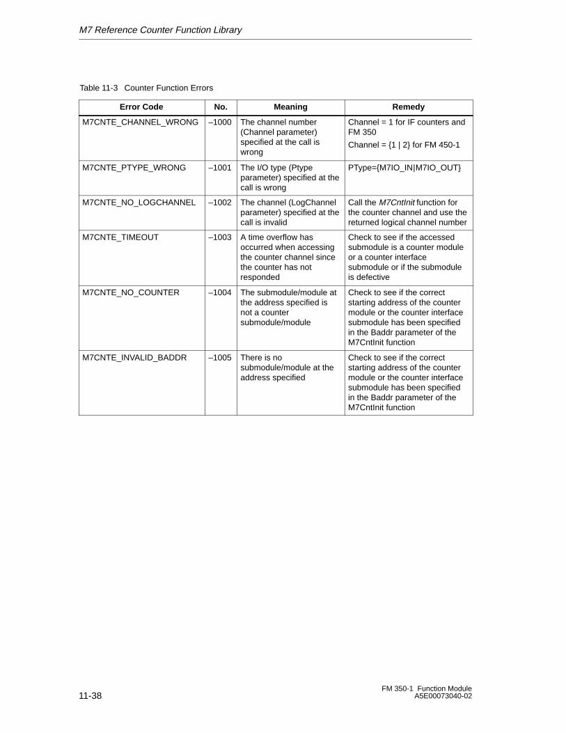
M7 Reference Counter Function Library
11-38FM 350-1 Function Module
A5E00073040-02
Table 11-3 Counter Function Errors
Error Code No. Meaning Remedy
M7CNTE_CHANNEL_WRONG –1000 The channel number(Channel parameter)specified at the call iswrong
Channel = 1 for IF counters andFM 350
Channel = {1 | 2} for FM 450-1
M7CNTE_PTYPE_WRONG –1001 The I/O type (Ptypeparameter) specified at thecall is wrong
PType={M7IO_IN|M7IO_OUT}
M7CNTE_NO_LOGCHANNEL –1002 The channel (LogChannelparameter) specified at thecall is invalid
Call the M7CntInit function forthe counter channel and use thereturned logical channel number
M7CNTE_TIMEOUT –1003 A time overflow hasoccurred when accessingthe counter channel sincethe counter has notresponded
Check to see if the accessedsubmodule is a counter moduleor a counter interfacesubmodule or if the submoduleis defective
M7CNTE_NO_COUNTER –1004 The submodule/module atthe address specified isnot a countersubmodule/module
Check to see if the correctstarting address of the countermodule or the counter interfacesubmodule has been specifiedin the Baddr parameter of theM7CntInit function
M7CNTE_INVALID_BADDR –1005 There is nosubmodule/module at theaddress specified
Check to see if the correctstarting address of the countermodule or the counter interfacesubmodule has been specifiedin the Baddr parameter of theM7CntInit function
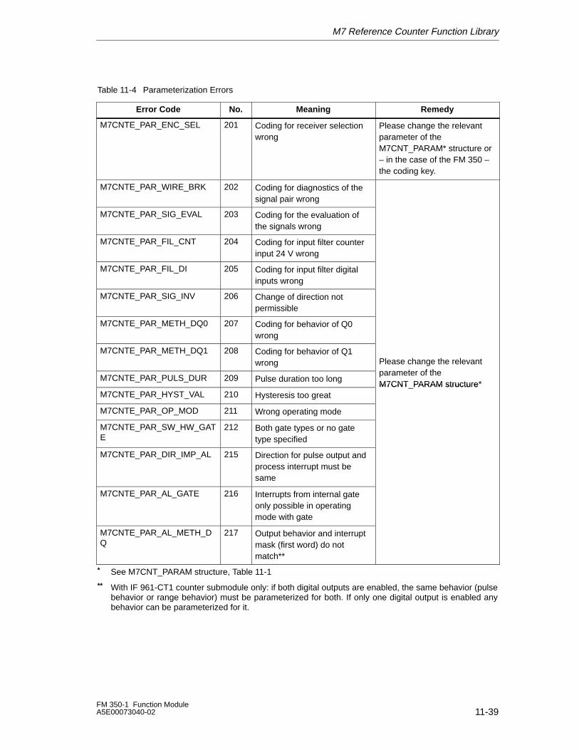
M7 Reference Counter Function Library
11-39FM 350-1 Function ModuleA5E00073040-02
Table 11-4 Parameterization Errors
Error Code No. Meaning Remedy
ÁÁÁÁÁÁÁÁÁÁÁÁÁÁÁÁÁÁÁÁÁÁÁÁÁÁÁÁÁÁÁÁÁÁÁÁÁÁÁÁÁÁÁÁÁÁÁÁÁÁ
M7CNTE_PAR_ENC_SEL ÁÁÁÁÁÁÁÁÁÁÁÁÁÁÁ
201 ÁÁÁÁÁÁÁÁÁÁÁÁÁÁÁÁÁÁÁÁÁÁÁÁÁÁÁÁÁÁÁÁÁÁÁÁÁÁÁÁÁÁÁÁÁ
Coding for receiver selectionwrong
ÁÁÁÁÁÁÁÁÁÁÁÁÁÁÁÁÁÁÁÁÁÁÁÁÁÁÁÁÁÁÁÁÁÁÁÁÁÁÁÁÁÁÁÁÁÁÁÁÁÁ
Please change the relevantparameter of theM7CNT_PARAM* structure or– in the case of the FM 350 –the coding key.
ÁÁÁÁÁÁÁÁÁÁÁÁÁÁÁÁÁÁÁÁÁÁÁÁÁÁÁÁÁÁ
M7CNTE_PAR_WIRE_BRK ÁÁÁÁÁÁÁÁÁ
202 ÁÁÁÁÁÁÁÁÁÁÁÁÁÁÁÁÁÁÁÁÁÁÁÁÁÁÁ
Coding for diagnostics of thesignal pair wrong
ÁÁÁÁÁÁÁÁÁÁÁÁÁÁÁÁÁÁÁÁÁÁÁÁÁÁÁÁÁÁÁÁÁÁÁÁÁÁÁÁ
ÁÁÁÁÁÁÁÁÁÁÁÁÁÁÁÁÁÁÁÁ
M7CNTE_PAR_SIG_EVAL ÁÁÁÁÁÁÁÁÁ
203 ÁÁÁÁÁÁÁÁÁÁÁÁÁÁÁÁÁÁÁÁÁÁÁÁÁÁÁ
Coding for the evaluation ofthe signals wrong
ÁÁÁÁÁÁÁÁÁÁÁÁÁÁÁÁÁÁÁÁÁÁÁÁÁÁÁÁÁÁÁÁÁÁÁÁÁÁÁÁ
ÁÁÁÁÁÁÁÁÁÁÁÁÁÁÁÁÁÁÁÁ
M7CNTE_PAR_FIL_CNT ÁÁÁÁÁÁÁÁÁ
204 ÁÁÁÁÁÁÁÁÁÁÁÁÁÁÁÁÁÁÁÁÁÁÁÁÁÁÁ
Coding for input filter counterinput 24 V wrong
ÁÁÁÁÁÁÁÁÁÁÁÁÁÁÁÁÁÁÁÁÁÁÁÁÁÁÁÁÁÁÁÁÁÁÁÁÁÁÁÁ
ÁÁÁÁÁÁÁÁÁÁ
M7CNTE_PAR_FIL_DI ÁÁÁÁÁÁ
205 ÁÁÁÁÁÁÁÁÁÁÁÁÁÁÁÁÁÁ
Coding for input filter digitalinputs wrong
ÁÁÁÁÁÁÁÁÁÁÁÁÁÁÁÁÁÁÁÁÁÁÁÁÁÁÁÁÁÁ
ÁÁÁÁÁÁÁÁÁÁÁÁÁÁÁÁÁÁÁÁ
M7CNTE_PAR_SIG_INVÁÁÁÁÁÁÁÁÁ
206ÁÁÁÁÁÁÁÁÁÁÁÁÁÁÁÁÁÁÁÁÁÁÁÁÁÁÁ
Change of direction notpermissible
ÁÁÁÁÁÁÁÁÁÁÁÁÁÁÁÁÁÁÁÁÁÁÁÁÁÁÁÁÁÁÁÁÁÁÁÁÁÁÁÁ
ÁÁÁÁÁÁÁÁÁÁÁÁÁÁÁÁÁÁÁÁ
M7CNTE_PAR_METH_DQ0ÁÁÁÁÁÁÁÁÁ
207ÁÁÁÁÁÁÁÁÁÁÁÁÁÁÁÁÁÁÁÁÁÁÁÁÁÁÁ
Coding for behavior of Q0wrong
ÁÁÁÁÁÁÁÁÁÁÁÁÁÁÁÁÁÁÁÁÁÁÁÁÁÁÁÁÁÁÁÁÁÁÁÁÁÁÁÁ
ÁÁÁÁÁÁÁÁÁÁÁÁÁÁÁÁÁÁÁÁ
M7CNTE_PAR_METH_DQ1 ÁÁÁÁÁÁÁÁÁ
208 ÁÁÁÁÁÁÁÁÁÁÁÁÁÁÁÁÁÁÁÁÁÁÁÁÁÁÁ
Coding for behavior of Q1wrong
ÁÁÁÁÁÁÁÁÁÁÁÁÁÁÁÁÁÁÁÁÁÁÁÁÁÁÁÁÁÁ
Please change the relevantt f thÁÁÁÁÁÁÁÁÁÁ
ÁÁÁÁÁÁÁÁÁÁM7CNTE_PAR_PULS_DUR ÁÁÁ
ÁÁÁ209 ÁÁÁÁÁÁÁÁÁÁÁÁÁÁÁÁÁÁ
Pulse duration too long ÁÁÁÁÁÁÁÁÁÁÁÁÁÁÁÁÁÁÁÁ
parameter of theM7CNT PARAM structure*ÁÁÁÁÁÁÁÁÁÁ
ÁÁÁÁÁÁÁÁÁÁM7CNTE_PAR_HYST_VAL
ÁÁÁÁÁÁ
210ÁÁÁÁÁÁÁÁÁÁÁÁÁÁÁÁÁÁ
Hysteresis too greatÁÁÁÁÁÁÁÁÁÁÁÁÁÁÁÁÁÁÁÁ
M7CNT_PARAM structure
ÁÁÁÁÁÁÁÁÁÁÁÁÁÁÁÁÁÁÁÁ
M7CNTE_PAR_OP_MODÁÁÁÁÁÁ
211ÁÁÁÁÁÁÁÁÁÁÁÁÁÁÁÁÁÁWrong operating mode
ÁÁÁÁÁÁÁÁÁÁÁÁÁÁÁÁÁÁÁÁÁÁÁÁÁÁÁÁÁÁ
ÁÁÁÁÁÁÁÁÁÁÁÁÁÁÁÁÁÁÁÁ
M7CNTE_PAR_SW_HW_GATE
ÁÁÁÁÁÁÁÁÁ
212ÁÁÁÁÁÁÁÁÁÁÁÁÁÁÁÁÁÁÁÁÁÁÁÁÁÁÁ
Both gate types or no gatetype specified
ÁÁÁÁÁÁÁÁÁÁÁÁÁÁÁÁÁÁÁÁÁÁÁÁÁÁÁÁÁÁÁÁÁÁÁÁÁÁÁÁ
ÁÁÁÁÁÁÁÁÁÁÁÁÁÁÁÁÁÁÁÁÁÁÁÁÁÁÁÁÁÁ
M7CNTE_PAR_DIR_IMP_ALÁÁÁÁÁÁÁÁÁÁÁÁ
215ÁÁÁÁÁÁÁÁÁÁÁÁÁÁÁÁÁÁÁÁÁÁÁÁÁÁÁÁÁÁÁÁÁÁÁÁ
Direction for pulse output andprocess interrupt must besame
ÁÁÁÁÁÁÁÁÁÁÁÁÁÁÁÁÁÁÁÁÁÁÁÁÁÁÁÁÁÁÁÁÁÁÁÁÁÁÁÁÁÁÁÁÁÁÁÁÁÁ
ÁÁÁÁÁÁÁÁÁÁÁÁÁÁÁÁÁÁÁÁÁÁÁÁÁÁÁÁÁÁ
M7CNTE_PAR_AL_GATE ÁÁÁÁÁÁÁÁÁÁÁÁ
216 ÁÁÁÁÁÁÁÁÁÁÁÁÁÁÁÁÁÁÁÁÁÁÁÁÁÁÁÁÁÁÁÁÁÁÁÁ
Interrupts from internal gateonly possible in operatingmode with gate
ÁÁÁÁÁÁÁÁÁÁÁÁÁÁÁÁÁÁÁÁÁÁÁÁÁÁÁÁÁÁÁÁÁÁÁÁÁÁÁÁÁÁÁÁÁÁÁÁÁÁ
ÁÁÁÁÁÁÁÁÁÁÁÁÁÁÁÁÁÁÁÁ
M7CNTE_PAR_AL_METH_DQ
ÁÁÁÁÁÁÁÁÁ
217 ÁÁÁÁÁÁÁÁÁÁÁÁÁÁÁÁÁÁÁÁÁÁÁÁÁÁÁ
Output behavior and interruptmask (first word) do notmatch**
ÁÁÁÁÁÁÁÁÁÁÁÁÁÁÁÁÁÁÁÁÁÁÁÁÁÁÁÁÁÁ
* See M7CNT_PARAM structure, Table 11-1
** With IF 961-CT1 counter submodule only: if both digital outputs are enabled, the same behavior (pulsebehavior or range behavior) must be parameterized for both. If only one digital output is enabled anybehavior can be parameterized for it.

M7 Reference Counter Function Library
11-40FM 350-1 Function Module
A5E00073040-02
Faults and Diagnostics
12-1FM 350-1 Function ModuleA5E00073040-02
Faults and Diagnostics
Chapter Overview
Operator errors, incorrect wiring or contradictory parameterization (position of thecoding connector does not match parameterization) can cause faults that themodule must indicate to the user.
Faults are divided into the following classes on the module:
• Faults displayed by the group error LED that indicate internal and externalmodule faults.
• Faults that can initiate a diagnostics interrupt.
• Operator errors.
These different classes of faults are indicated and displayed at different positionsand must be acknowledged in different ways.
You will find the following described in this chapter:
• The faults that can occur
• Where these faults are indicated
• How you acknowledge the faults.
Section Description Page
12.1 Fault Indication via the Group Error LED 12-2
12.2 Initiation of Diagnostics Interrupts 12-3
12.3 Data Errors 12-7
12.4 Operator Errors 12-9
12
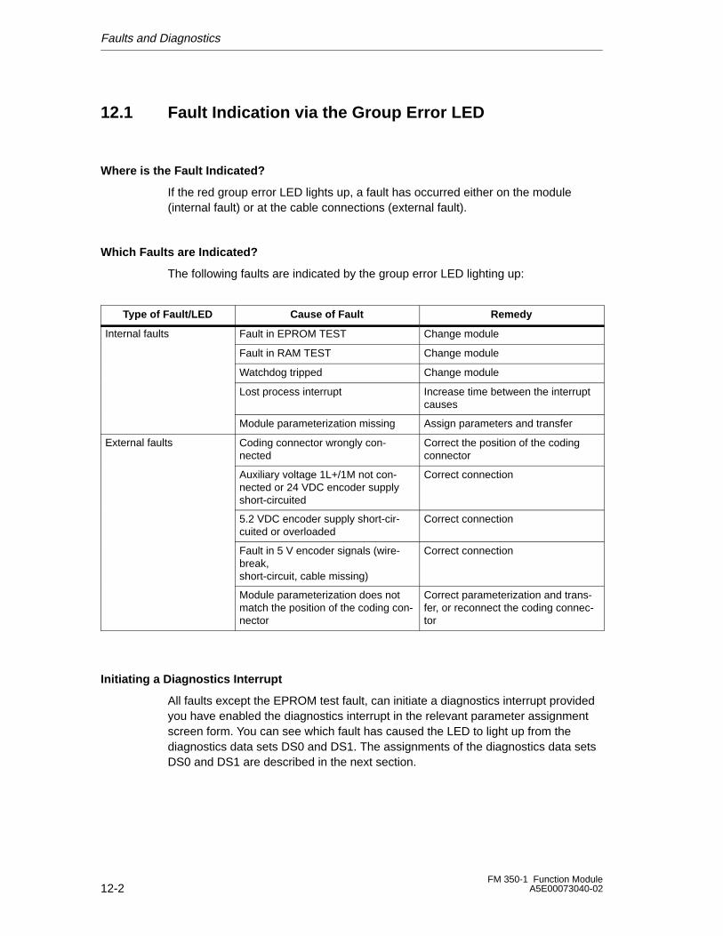
Faults and Diagnostics
12-2FM 350-1 Function Module
A5E00073040-02
12.1 Fault Indication via the Group Error LED
Where is the Fault Indicated?
If the red group error LED lights up, a fault has occurred either on the module(internal fault) or at the cable connections (external fault).
Which Faults are Indicated?
The following faults are indicated by the group error LED lighting up:
Type of Fault/LED Cause of Fault Remedy
Internal faults Fault in EPROM TEST Change module
Fault in RAM TEST Change module
Watchdog tripped Change module
Lost process interrupt Increase time between the interruptcauses
Module parameterization missing Assign parameters and transfer
External faults Coding connector wrongly con-nected
Correct the position of the codingconnector
Auxiliary voltage 1L+/1M not con-nected or 24 VDC encoder supplyshort-circuited
Correct connection
5.2 VDC encoder supply short-cir-cuited or overloaded
Correct connection
Fault in 5 V encoder signals (wire-break,short-circuit, cable missing)
Correct connection
Module parameterization does notmatch the position of the coding con-nector
Correct parameterization and trans-fer, or reconnect the coding connec-tor
Initiating a Diagnostics Interrupt
All faults except the EPROM test fault, can initiate a diagnostics interrupt providedyou have enabled the diagnostics interrupt in the relevant parameter assignmentscreen form. You can see which fault has caused the LED to light up from thediagnostics data sets DS0 and DS1. The assignments of the diagnostics data setsDS0 and DS1 are described in the next section.
Faults and Diagnostics
12-3FM 350-1 Function ModuleA5E00073040-02
12.2 Initiation of Diagnostics Interrupts
What is a Diagnostics Interrupt?
If a user program is to respond to an internal or external fault, you canparameterize a diagnostics interrupt that stops the cyclical program of the CPU andcalls the diagnostics interrupt OB (OB82).
Which Events Can Initiate a Diagnostics Interrupt?
The list shows you which events can initiate a diagnostics interrupt:
• External auxiliary voltage 1L+/1M short-circuited or overloaded
• Fault in 5.2 VDC encoder supply
• Module parameterization missing
• Error in module parameterization
• Watchdog tripped
• RAM defective
• Process interrupt lost
• Fault in signal A (wirebreak, short-circuit, cable missing)
• Fault in signal B (wirebreak, short-circuit, cable missing)
• Fault in signal N (wirebreak, short-circuit, cable missing)
Enabling the Diagnostics Interrupt
You disable or enable the interrupts for the module in the parameter assignmentscreen forms and you decide there whether the module is to initiate a diagnosticsinterrupt and/or a process interrupt.
Responses to a Diagnostics Interrupt
If an event occurs that can initiate a diagnostics interrupt, the following happens:
• The diagnostics information is stored in diagnostics data sets DS0 and DS1.
• The group error LED lights up
• The diagnostics interrupt OB is called (OB82).
• The diagnostics data set DS0 is entered in the start information of thediagnostics interrupt OB.
• The count continues unchanged.
If OB82 has not been programmed, the CPU goes to STOP.
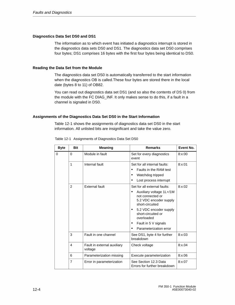
Faults and Diagnostics
12-4FM 350-1 Function Module
A5E00073040-02
Diagnostics Data Set DS0 and DS1
The information as to which event has initiated a diagnostics interrupt is stored inthe diagnostics data sets DS0 and DS1. The diagnostics data set DS0 comprisesfour bytes; DS1 comprises 16 bytes with the first four bytes being identical to DS0.
Reading the Data Set from the Module
The diagnostics data set DS0 is automatically transferred to the start informationwhen the diagnostics OB is called.These four bytes are stored there in the localdate (bytes 8 to 11) of OB82.
You can read out diagnostics data set DS1 (and so also the contents of DS 0) fromthe module with the FC DIAG_INF. It only makes sense to do this, if a fault in achannel is signaled in DS0.
Assignments of the Diagnostics Data Set DS0 in the Start Information
Table 12-1 shows the assignments of diagnostics data set DS0 in the startinformation. All unlisted bits are insignificant and take the value zero.
Table 12-1 Assignments of Diagnostics Data Set DS0
Byte Bit Meaning Remarks Event No.
0 0 Module in fault Set for every diagnosticsevent
8:x:00
1 Internal fault Set for all internal faults:
• Faults in the RAM test
• Watchdog tripped
• Lost process interrupt
8:x:01
2 External fault Set for all external faults:
• Auxiliary voltage 1L+/1Mnot connected or 5.2 VDC encoder supplyshort-circuited
• 5.2 VDC encoder supplyshort-circuited oroverloaded
• Fault in 5 V signals
• Parameterization error
8:x:02
3 Fault in one channel See DS1, byte 4 for furtherbreakdown
8:x:03
4 Fault in external auxiliaryvoltage
Check voltage 8:x.04
6 Parameterization missing Execute parameterization 8:x:06
7 Error in parameterization See Section 12.3 DataErrors for further breakdown
8:x:07
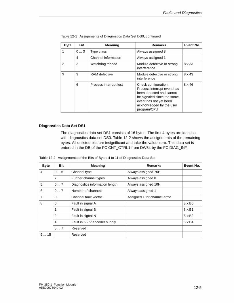
Faults and Diagnostics
12-5FM 350-1 Function ModuleA5E00073040-02
Table 12-1 Assignments of Diagnostics Data Set DS0, continued
Byte Event No.RemarksMeaningBit
1 0 ... 3 Type class Always assigned 8
4 Channel information Always assigned 1
2 3 Watchdog tripped Module defective or stronginterference
8:x:33
3 3 RAM defective Module defective or stronginterference
8:x:43
6 Process interrupt lost Check configuration.Process interrupt event hasbeen detected and cannotbe signaled since the sameevent has not yet beenacknowledged by the userprogram/CPU
8:x:46
Diagnostics Data Set DS1
The diagnostics data set DS1 consists of 16 bytes. The first 4 bytes are identicalwith diagnostics data set DS0. Table 12-2 shows the assignments of the remainingbytes. All unlisted bits are insignificant and take the value zero. This data set isentered in the DB of the FC CNT_CTRL1 from DW54 by the FC DIAG_INF.
Table 12-2 Assignments of the Bits of Bytes 4 to 11 of Diagnostics Data Set
Byte Bit Meaning Remarks Event No.
4 0 ... 6 Channel type Always assigned 76H
7 Further channel types Always assigned 0
5 0 ... 7 Diagnostics information length Always assigned 10H
6 0 ... 7 Number of channels Always assigned 1
7 0 Channel fault vector Assigned 1 for channel error
8 0 Fault in signal A 8:x:B0
1 Fault in signal B 8:x:B1
2 Fault in signal N 8:x:B2
4 Fault in 5.2 V encoder supply 8:x:B4
5 ... 7 Reserved
9 ... 15 Reserved
Faults and Diagnostics
12-6FM 350-1 Function Module
A5E00073040-02
How Does the Diagnostics Text Appear in the Diagnostics Buffer?
If you want to enter the diagnostics message in the diagnostics buffer, you mustcall the SFC 52 ‘Enter user-specific message in diagnostics buffer’ in the userprogram. The event number of the diagnostics message in each case is specifiedin the input parameter EVENTN. The interrupt is entered in the diagnostics bufferwith x=1 as incoming and with x=0 as outgoing. The diagnostics buffer contains therelevant diagnostics text in the ‘Meaning’ column as well as the time of the entry.
Default Setting
The diagnostics interrupt is disabled in the default setting.
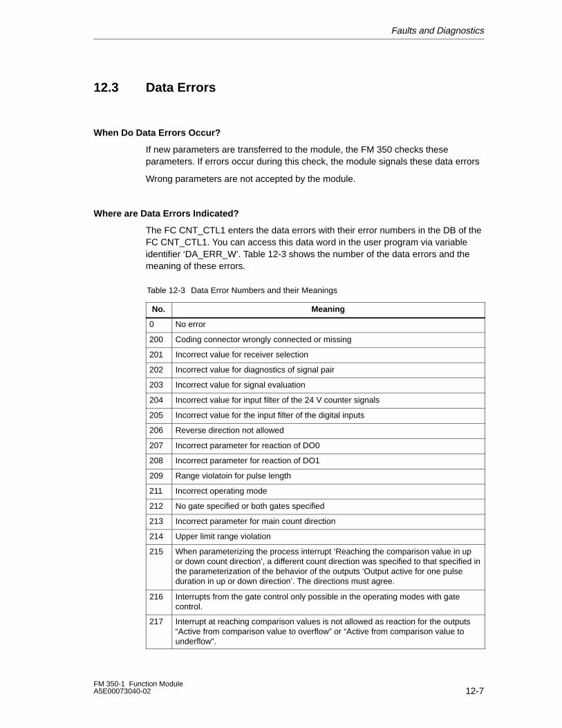
Faults and Diagnostics
12-7FM 350-1 Function ModuleA5E00073040-02
12.3 Data Errors
When Do Data Errors Occur?
If new parameters are transferred to the module, the FM 350 checks theseparameters. If errors occur during this check, the module signals these data errors
Wrong parameters are not accepted by the module.
Where are Data Errors Indicated?
The FC CNT_CTL1 enters the data errors with their error numbers in the DB of theFC CNT_CTL1. You can access this data word in the user program via variableidentifier ‘DA_ERR_W’. Table 12-3 shows the number of the data errors and themeaning of these errors.
Table 12-3 Data Error Numbers and their Meanings
No. Meaning
0 No error
200 Coding connector wrongly connected or missing
201 Incorrect value for receiver selection
202 Incorrect value for diagnostics of signal pair
203 Incorrect value for signal evaluation
204 Incorrect value for input filter of the 24 V counter signals
205 Incorrect value for the input filter of the digital inputs
206 Reverse direction not allowed
207 Incorrect parameter for reaction of DO0
208 Incorrect parameter for reaction of DO1
209 Range violatoin for pulse length
211 Incorrect operating mode
212 No gate specified or both gates specified
213 Incorrect parameter for main count direction
214 Upper limit range violation
215 When parameterizing the process interrupt ‘Reaching the comparison value in upor down count direction’, a different count direction was specified to that specified inthe parameterization of the behavior of the outputs ‘Output active for one pulseduration in up or down direction’. The directions must agree.
216 Interrupts from the gate control only possible in the operating modes with gatecontrol.
217 Interrupt at reaching comparison values is not allowed as reaction for the outputs“Active from comparison value to overflow” or “Active from comparison value tounderflow”.
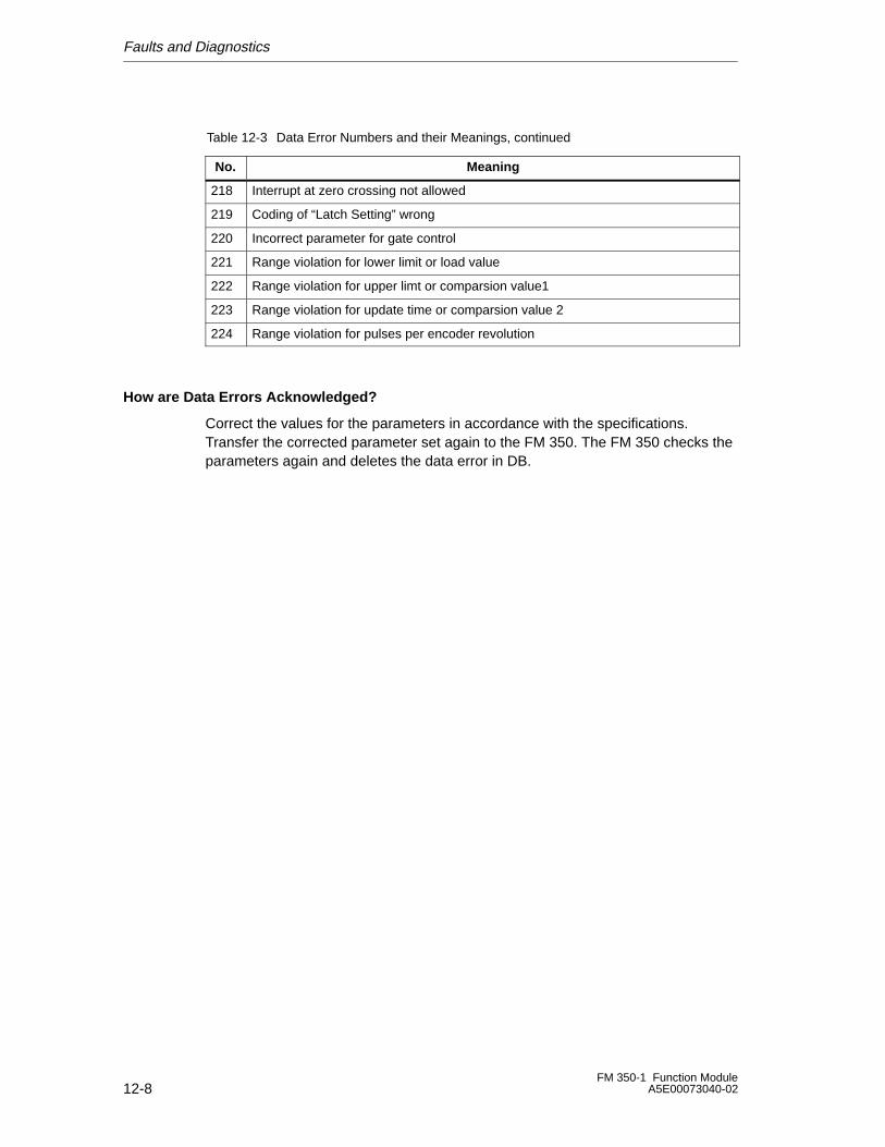
Faults and Diagnostics
12-8FM 350-1 Function Module
A5E00073040-02
Table 12-3 Data Error Numbers and their Meanings, continued
MeaningNo.
218 Interrupt at zero crossing not allowed
219 Coding of “Latch Setting” wrong
220 Incorrect parameter for gate control
221 Range violation for lower limit or load value
222 Range violation for upper limt or comparsion value1
223 Range violation for update time or comparsion value 2
224 Range violation for pulses per encoder revolution
How are Data Errors Acknowledged?
Correct the values for the parameters in accordance with the specifications.Transfer the corrected parameter set again to the FM 350. The FM 350 checks theparameters again and deletes the data error in DB.
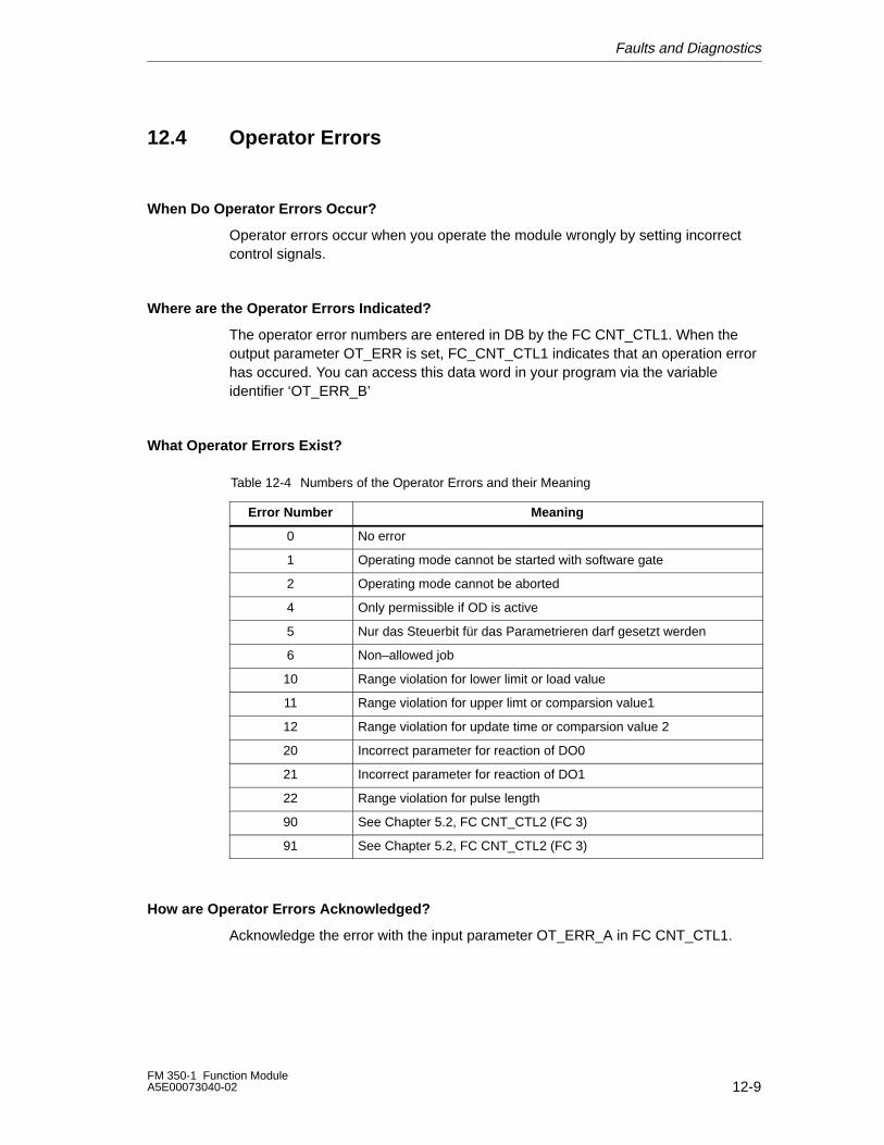
Faults and Diagnostics
12-9FM 350-1 Function ModuleA5E00073040-02
12.4 Operator Errors
When Do Operator Errors Occur?
Operator errors occur when you operate the module wrongly by setting incorrectcontrol signals.
Where are the Operator Errors Indicated?
The operator error numbers are entered in DB by the FC CNT_CTL1. When theoutput parameter OT_ERR is set, FC_CNT_CTL1 indicates that an operation errorhas occured. You can access this data word in your program via the variableidentifier ‘OT_ERR_B’
What Operator Errors Exist?
Table 12-4 Numbers of the Operator Errors and their Meaning
Error Number Meaning
0 No error
1 Operating mode cannot be started with software gate
2 Operating mode cannot be aborted
4 Only permissible if OD is active
5 Nur das Steuerbit für das Parametrieren darf gesetzt werden
6 Non–allowed job
10 Range violation for lower limit or load value
11 Range violation for upper limt or comparsion value1
12 Range violation for update time or comparsion value 2
20 Incorrect parameter for reaction of DO0
21 Incorrect parameter for reaction of DO1
22 Range violation for pulse length
90 See Chapter 5.2, FC CNT_CTL2 (FC 3)
91 See Chapter 5.2, FC CNT_CTL2 (FC 3)
How are Operator Errors Acknowledged?
Acknowledge the error with the input parameter OT_ERR_A in FC CNT_CTL1.

Faults and Diagnostics
12-10FM 350-1 Function Module
A5E00073040-02
A-1FM 350-1 Function ModuleA5E00073040-02
Technical Specifications
General Technical Specifications
The following technical specifications are described in the Reference ManualProgrammable Controllers S7-300/M7-300, Module Specifications.
• Electromagnetic compatibility
• Shipping and storage conditions
• Mechanical and climatic ambient conditions
• Details of insulation tests, safety class and degree of protection
• Certifications, approvals and standards
! Warning
Personal injury and material damage may occur.
In potentially explosive areas, personal injury and material damage can occur ifyou unplug plug-and-socket connections while an S7-300 is operating.
Always de-energize the S7-300 in potentially explosive areas before you undoplug-and-socket connections.
! Warning
WARNING - DO NOT DISCONNECT WHILE CIRCUIT IS LIVEUNLESS LOCATION IS KNOWN TO BE NONHAZARDOUS
A
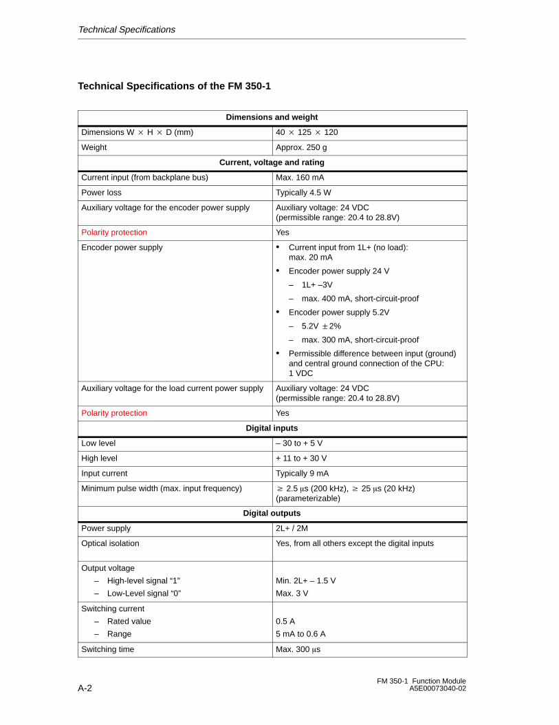
Technical Specifications
A-2FM 350-1 Function Module
A5E00073040-02
Technical Specifications of the FM 350-1
Dimensions and weight
Dimensions W � H � D (mm) 40 � 125 � 120
Weight Approx. 250 g
Current, voltage and rating
Current input (from backplane bus) Max. 160 mA
Power loss Typically 4.5 W
Auxiliary voltage for the encoder power supply Auxiliary voltage: 24 VDC (permissible range: 20.4 to 28.8V)
Polarity protection Yes
Encoder power supply • Current input from 1L+ (no load):max. 20 mA
• Encoder power supply 24 V
– 1L+ –3V
– max. 400 mA, short-circuit-proof
• Encoder power supply 5.2V
– 5.2V �2%
– max. 300 mA, short-circuit-proof
• Permissible difference between input (ground)and central ground connection of the CPU:1 VDC
Auxiliary voltage for the load current power supply Auxiliary voltage: 24 VDC (permissible range: 20.4 to 28.8V)
Polarity protection Yes
Digital inputs
Low level – 30 to + 5 V
High level + 11 to + 30 V
Input current Typically 9 mA
Minimum pulse width (max. input frequency) � 2.5 �s (200 kHz), � 25 �s (20 kHz)(parameterizable)
Digital outputs
Power supply 2L+ / 2M
Optical isolation Yes, from all others except the digital inputs
Output voltage
– High-level signal “1”
– Low-Level signal “0”
Min. 2L+ – 1.5 V
Max. 3 V
Switching current
– Rated value
– Range
0.5 A
5 mA to 0.6 A
Switching time Max. 300 �s
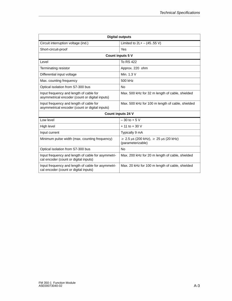
Technical Specifications
A-3FM 350-1 Function ModuleA5E00073040-02
Digital outputs
Circuit interruption voltage (ind.) Limited to 2L+ – (45..55 V)
Short-circuit-proof Yes
Count inputs 5 V
Level To RS 422
Terminating resistor Approx. 220 ohm
Differential input voltage Min. 1.3 V
Max. counting frequency 500 kHz
Optical isolation from S7-300 bus No
Input frequency and length of cable for asymmetrical encoder (count or digital inputs)
Max. 500 kHz for 32 m length of cable, shielded
Input frequency and length of cable for asymmetrical encoder (count or digital inputs)
Max. 500 kHz for 100 m length of cable, shielded
Count inputs 24 V
Low level – 30 to + 5 V
High level + 11 to + 30 V
Input current Typically 9 mA
Minimum pulse width (max. counting frequency) � 2.5 �s (200 kHz), � 25 �s (20 kHz)(parameterizable)
Optical isolation from S7-300 bus No
Input frequency and length of cable for asymmetri-cal encoder (count or digital inputs)
Max. 200 kHz for 20 m length of cable, shielded
Input frequency and length of cable for asymmetri-cal encoder (count or digital inputs)
Max. 20 kHz for 100 m length of cable, shielded

Technical Specifications
A-4FM 350-1 Function Module
A5E00073040-02
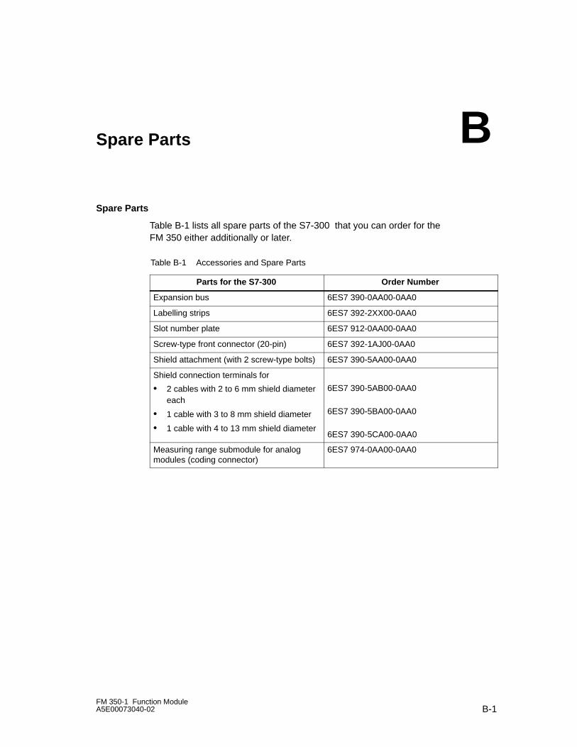
B-1FM 350-1 Function ModuleA5E00073040-02
Spare Parts
Spare Parts
Table B-1 lists all spare parts of the S7-300 that you can order for theFM 350 either additionally or later.
Table B-1 Accessories and Spare Parts
Parts for the S7-300 Order Number
Expansion bus 6ES7 390-0AA00-0AA0
Labelling strips 6ES7 392-2XX00-0AA0
Slot number plate 6ES7 912-0AA00-0AA0
Screw-type front connector (20-pin) 6ES7 392-1AJ00-0AA0
Shield attachment (with 2 screw-type bolts) 6ES7 390-5AA00-0AA0
Shield connection terminals for
• 2 cables with 2 to 6 mm shield diametereach
• 1 cable with 3 to 8 mm shield diameter
• 1 cable with 4 to 13 mm shield diameter
6ES7 390-5AB00-0AA0
6ES7 390-5BA00-0AA0
6ES7 390-5CA00-0AA0
Measuring range submodule for analogmodules (coding connector)
6ES7 974-0AA00-0AA0
B

13
Spare Parts
B-2FM 350-1 Function Module
A5E00073040-02
Spare Parts
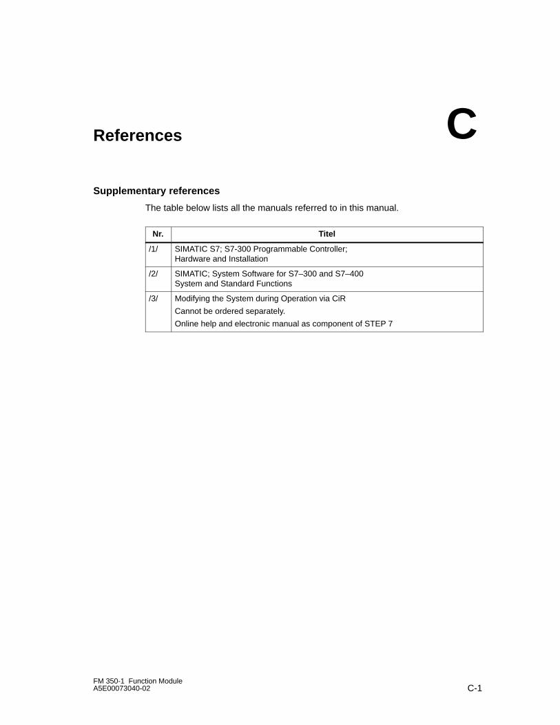
C-1FM 350-1 Function ModuleA5E00073040-02
References
Supplementary references
The table below lists all the manuals referred to in this manual.
Nr. Titel
/1/ SIMATIC S7; S7-300 Programmable Controller;Hardware and Installation
/2/ SIMATIC; System Software for S7–300 and S7–400System and Standard Functions
/3/ Modifying the System during Operation via CiR
Cannot be ordered separately.
Online help and electronic manual as component of STEP 7
C

References
C-2FM 350-1 Function Module
A5E00073040-02
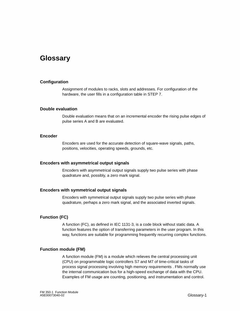
Glossary-1FM 350-1 Function ModuleA5E00073040-02
Glossary
Configuration
Assignment of modules to racks, slots and addresses. For configuration of thehardware, the user fills in a configuration table in STEP 7.
Double evaluation
Double evaluation means that on an incremental encoder the rising pulse edges ofpulse series A and B are evaluated.
Encoder
Encoders are used for the accurate detection of square-wave signals, paths,positions, velocities, operating speeds, grounds, etc.
Encoders with asymmetrical output signals
Encoders with asymmetrical output signals supply two pulse series with phasequadrature and, possibly, a zero mark signal.
Encoders with symmetrical output signals
Encoders with symmetrical output signals supply two pulse series with phasequadrature, perhaps a zero mark signal, and the associated inverted signals.
Function (FC)
A function (FC), as defined in IEC 1131-3, is a code block without static data. Afunction features the option of transferring parameters in the user program. In thisway, functions are suitable for programming frequently recurring complex functions.
Function module (FM)
A function module (FM) is a module which relieves the central processing unit(CPU) on programmable logic controllers S7 and M7 of time-critical tasks ofprocess signal processing involving high memory requirements . FMs normally usethe internal communication bus for a high-speed exchange of data with the CPU.Examples of FM usage are counting, positioning, and instrumentation and control.
Glossary
Glossary-2FM 350-1 Function Module
A5E00073040-02
Initiator
An initiator is a simple BERO proximity switch without directional information. Itthus merely provides a count signal. In this instance, only the rising pulse edges ofsignal A are counted. The direction of counting must be specified by the user.
Pulse duration
With the pulse duration, you specify the minimum time an output should be set.
Push–Pull
The output of the encoder actively switches to 0 V (ground) and actively to +24 V.
Quadruple evaluation
Quadruple evaluation means that on an incremental encoder all the pulse edges ofpulse series A and B are evaluated.
SFC
An SFC (system function) is a function that is integrated in the operating system ofthe CPU and can be called, if required, in the STEP 7 user program.
Single evaluation
Single evaluation means that on an incremental encoder the rising pulse edge ofpulse series A is evaluated.
Sink output
The output of the encoder actively switches to 0 V (ground).
Source output
The output of the encoder actively switches to +24 V.
STOP
STOP as an international expression – for example, as an operating modecommand.
STOPP
STOPP as an expression in the manual when a command is not meant (STOPP isGerman for STOP).
Glossary
Glossary-3FM 350-1 Function ModuleA5E00073040-02
Zero mark
The zero mark is located on the third track of an incremental encoder. After eachrotation, the zero mark supplies a zero mark signal.
Zero mark signal
The zero mark signal is read out by an incremental encoder after every rotation.

Glossary
Glossary-4FM 350-1 Function Module
A5E00073040-02
Index-1FM 350-1 Function ModuleA5E00073040-02
Index
Symbols+/–31Bit counting range limit, 8-20
Numbers24 V encoder signals, 3-5
input filter, 1-3, 3-5, 9-624 V signals, 9-524 VDC encoder supply, 3-432Bit counting range limit, 8-205 V differential signals, 9-35.2 VDC encoder supply, 3-4
AAcknowledgement principle, complete, 5-31Auxiliary voltage 1L+, 1M, 3-4
BBehavior of the digital outputs, marginal
conditions, 8-34
CCables, 3-7
cross-section, 3-8Calling, 4-3Central Operation, 1-3Check-back interface
Count modes, 5-20Measure modes, 5-27
Checklistmechanical installation, 7-2parameterization, 7-4
CNT_CTL2 function, 5-10Coding connector, 1-8Coding key, correct position, 2-3Command: Latch/Retrigger, 8-44Command: open and close gate, 8-21Command: set counter, 8-38
Command:Latch, 8-46Command:Measuring times, 8-48Command:Open and close gate, 8-62Commands, 8-7, 8-54
give, 8-2Comparison value, 8-27Connection
incremental 24V Encoder, 3-8incremental 5 V encoder, 3-7
Continuous periodic measurement, 8-59Continuous periodic measurement mode, 8-59Control bits, 8-2Control interface
Count modes, 5-16Measure modes, 5-24
Control- and check-back interface, Accessingwith STEP 7 programming, 5-2
Count modes, 8-4Check-back interface, 5-20Control interface, 5-16
Count range, maximum, 8-6Counter signals, cables, 3-7CPU STOP, Behaviour, 5-36
DData errors, 12-7DB parameters for counting, transferring
values, 5-7DB parameters for measuring, transferring
values, 5-9DI Set. See digital inputsDI Start. See digital inputsDI Stop. See digital inputsDiagnostic data set DS0, assignments, 12-4Diagnostics data set DS1, assignments, 12-5Diagnostics interrupt, 12-2, 12-3
enabling, 12-3OB 82, 12-3
Digital input DI Start, Status, 8-22Digital input DI Stop, Status, 8-22Digital input Start DI, Status, 8-63Digital input Stop DI, Status, 8-63
Index
Index-2FM 350-1 Function Module
A5E00073040-02
Digital inputs, 3-5cables, 3-7cables, shielded, 3-7input filter, 3-6
Digital outputs, 3-6behaviour, 8-67enable, 8-66enabling, 8-27setting and resetting, 8-28status, 8-30, 8-68
EENSET_DN, 8-39ENSET_UP, 8-39Ersatzteile, C-1External faults, 12-2
FFM 350-1
Count modes, 8-4Measure modes, 8-49Overview of the commands, 8-7, 8-54
FM 350-1, S7-400 configuration, 1-10Frequency measurement, 8-55Frequency measurement mode , 8-55Front connector, 1-7
terminal assignments, 3-2wiring, 3-9
Front connector coding, 1-8Front connector of the FM 350-1, 3-2Functions, Technical data, 5-15
GGate Stop function, 8-64Gate stop function, 8-14, 8-24Group error LED, 12-2
HHardware gate
edge-controlled opening and closing, 8-22level-controlled opening and closing, 8-21status, 8-22
HW gate, Status , 8-63HW gate:edge-controlled opening and closing,
8-63
HW gate:level-controlled opening and closing,8-62
Hysteresis, 1-3, 8-35
IInput delay, 3-6Input filter, 3-6Internal faults, 12-2
LLabeling strips, 1-8Latch, 8-46LEDs, function, 1-9Load value, 1-2, 8-38Load voltage, 3-6
MMain application area, 1-5Maximum number, of FM 350-1 used, 2-2Measure
Frequency, 8-55Period, 8-59RPM, 8-57
Measure modes, 8-49Check-back interface, 5-27Control interface, 5-24
Measuring times, 8-48Mechanical configuration, 2-2
OOB 40, 8-70
start information, 8-70OB82, 12-3Open and close the hardware gate, 8-13Open and close the software gate, 8-18Opening and closing the software gate, 8-9,
8-13Operating modes, select, 8-2Operator errors, 12-9Order number, 1-8Overflow, 8-20
Index
Index-3FM 350-1 Function ModuleA5E00073040-02
PPeriodic counting mode, 8-15Process interrupt, 1-2, 8-69
enabling, 8-69initiate, 8-69OB 40, 8-70
Programming, without FCs, 5-16Pulse duration
default value, 8-32range of values, 8-32
QQ0. See digital outputsQ1. See digital outputQuadruple evaluation, 9-8
RRestart coordination, 5-35RPM measurement, 8-57RPM measurement mode, 8-57
SSafety rules, 2-2Selecting the gate function, 8-8, 8-13, 8-18SET, 8-38Set counter, with digital input I2, 8-39Setting the counter
via the user program, 8-38with an external signal, 8-39with the zero mark, 8-41
Setting: behavior of the digital outputs, 8-27Setting: counting range limit, 8-20Setting:Behaviour of the digital outputs, 8-66Settings, select, 8-2Single counting mode, 8-10Slots, permitted, 2-2
Software gateopening and closing, 8-23status, 8-23
Status bits, 8-2Resetting, 5-34
SW gateOpening and closing, 8-64Status , 8-64
Symmetric encoders, 9-3
TTerminal assignment, 1-8Transferring values
DB parameters for counting, 5-7DB parameters for measuring, 5-9time required (with function), 5-7time required (without function), 5-33with function, 5-6without function, 5-32
UUnderflow, 8-20
VValues, Reading back, 5-34Version, 1-8View of module, 1-7Voltage supply, of the encoders, 3-4
WWire end ferrule, 3-8
ZZero pass, 8-20

Index
Index-4FM 350-1 Function Module
A5E00073040-02