8/7/2019 Shell exploration plan
http://slidepdf.com/reader/full/shell-exploration-plan 1/48
Tolbert, Michael
From: Tolbert, Michael
Sent: Tuesday, February 22, 2011 1:56 PM
To: '[email protected]'
Cc: Peuler, Elizabeth; Hill, Chiquita; Wetzel, Nick; Saucier, MichaelSubject: Supplemental Exploration Plan S-7445 for Lease OCS-G 7493 (GB 427)
Importance: High
Page 1 of 1
2/22/2011
This email is to notify you that the following Supplemental Exploration Plan received October 28, 2010, amendedNovember 19 and 30, December 3 and 9, 2010, and January 6, 21, 27, and February 18, 2011, has been
deemed submitted in accordance with 30 CFR 250.231(a) and 232(d) as of February 22, 2011:
Control Number - S-7445 Type - Supplemental Exploration Plan Operator – Shell Offshore Inc. Lease(s) - OCS-G 7493 (Block 427, Garden Banks Area) Activities Proposed – Add Wells O, P, and Q
Michael Tolbert
Petroleum Engineer
Office of Field Operations, Plans Section
Phone: (504) 736-2867
email: [email protected]
8/7/2019 Shell exploration plan
http://slidepdf.com/reader/full/shell-exploration-plan 2/48
Shell Offshore Inc
P. O. Box 61933New Orleans, LA 70161-1933
United States of AmericaTel +1 504 728 7215Fax +1 504 728 6747
Email [email protected]
February 17, 2011
Regional Supervisor
Office of Field OperationsBureau of Ocean Energy ManagementRegulation & Enforcement1201 Elmwood Park BoulevardNew Orleans, LA 70123-2394
Attn: Plans GroupMS 5321
SUBJECT: Amended Supplemental Exploration Plan
OCS-G 7493, Garden Banks Block 427
Garden Banks 471 Unit
Offshore, LouisianaS-07445
Shell submitted subject Supplemental Exploration Plan on October 28, 2010. At this time we are requesting an amendment to the plan to include the information contained in the attachments to this letter. Theamendments include an update to our worst case discharge number, a change in our proposed anchorpattern, and an update to our proposed schedule. These amendments do not change the analysis andconclusions in the previously submitted EIA. All additional information in our original supplemental planremains as previously submitted.
The NTL 2010-06 Worst Case Blowout requirements for our Regional Oil Spill Response Plan highestexploration well, were previously submitted October 26, 2010 with our Supplemental Exploration Plan forMississippi Canyon Blocks 391, 392 and 348, Plan Control No. R-05066.
Should you require any additional information, please contact me as indicated above.
Kind regards
Sylvia A. Bellone
8/7/2019 Shell exploration plan
http://slidepdf.com/reader/full/shell-exploration-plan 3/48
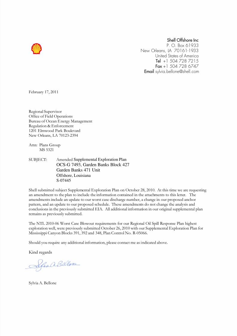
U. S. Department of the Interior OMB Control Number: 1010-0051
Minerals Management Service OMB Approval Expires: 12/31/2011
OCS PLAN INFORMATION FORM
General Information
Type of OCS Plan: X Exploration Plan (EP) Development Operations Coordination Document (DOCD)
Company Name: Shell Offshore Inc. MMS Operator Number: 0689
Address: P. O. Box 61933 Contact Person: Sylvia Bellone
New Orleans, LA 70161-1933 Phone Number: (504) 728-7215
E-Mail Address: [email protected]
Lease(s): OCS-G 7493 Area: Garden Banks Block(s): 427 Project Name (If Applicable): NA
Objective(s): X Oil Gas Sulphur Salt Onshore Base: Fourchon & Amelia Distance to Closest Land (Miles): 130
Description of Proposed Activities (Mark all that apply)
X Exploration drilling Development drilling
Well completion Installation of production platformWell test flaring (for more than 48 hours) Installation of production facilities
Installation of caisson or platform as well protection structure Installation of satellite structure
Installation of subsea wellheads and/or manifolds Commence production
Installation of lease term pipelines Other (Specify and describe)
Have you submitted or do you plan to submit a Conservation Information Document to accompany this plan? Yes X No
Do you propose to use new or unusual technology to conduct your activities? Yes X No
Do you propose any facility that will serve as a host facility for deepwater subsea development? Yes X No
Do you propose any activities that may disturb an MMS-designated high-probability archaeological area? X Yes No
Have all of the surface locations of your proposed activities been previously reviewed and approved by MMS? Yes X No
Tentative Schedule of Proposed Activities
Proposed Activity Start Date End Date No. of Days
Preset anchors 3/7/11 4/7/11 30
Drill O 4/7/11 9/14/11 160
Drill P 4/7/12 9/14/12 160
Drill Q 4/7/13 9/14/13 160
Description of Drilling Rig Description of Production Platform
Jackup Drillship Caisson Tension leg platform Gorilla Jackup Platform rig Well protector Compliant tower
X Semisubmersible Submersible Fixed platform Guyed tower
DP Semisubmersible Other (Attach Description) Subsea manifold Floating production system
Drilling Rig Name (If Known): Noble Jim Thompson Spar Other (Attach Description)
Description of Lease Term Pipelines
From (Facility/Area/Block) To (Facility/Area/Block) Diameter (Inches) Length (Feet)
N/A
MMSMMSMMSMMS Form MMS-137 (December 2008 – Supersedes all previous editions of form MMS=137 which may not be used.) Page 1 of 4
PUBLIC INFORMATIONPUBLIC INFORMATIONPUBLIC INFORMATIONPUBLIC INFORMATION

8/7/2019 Shell exploration plan
http://slidepdf.com/reader/full/shell-exploration-plan 4/48
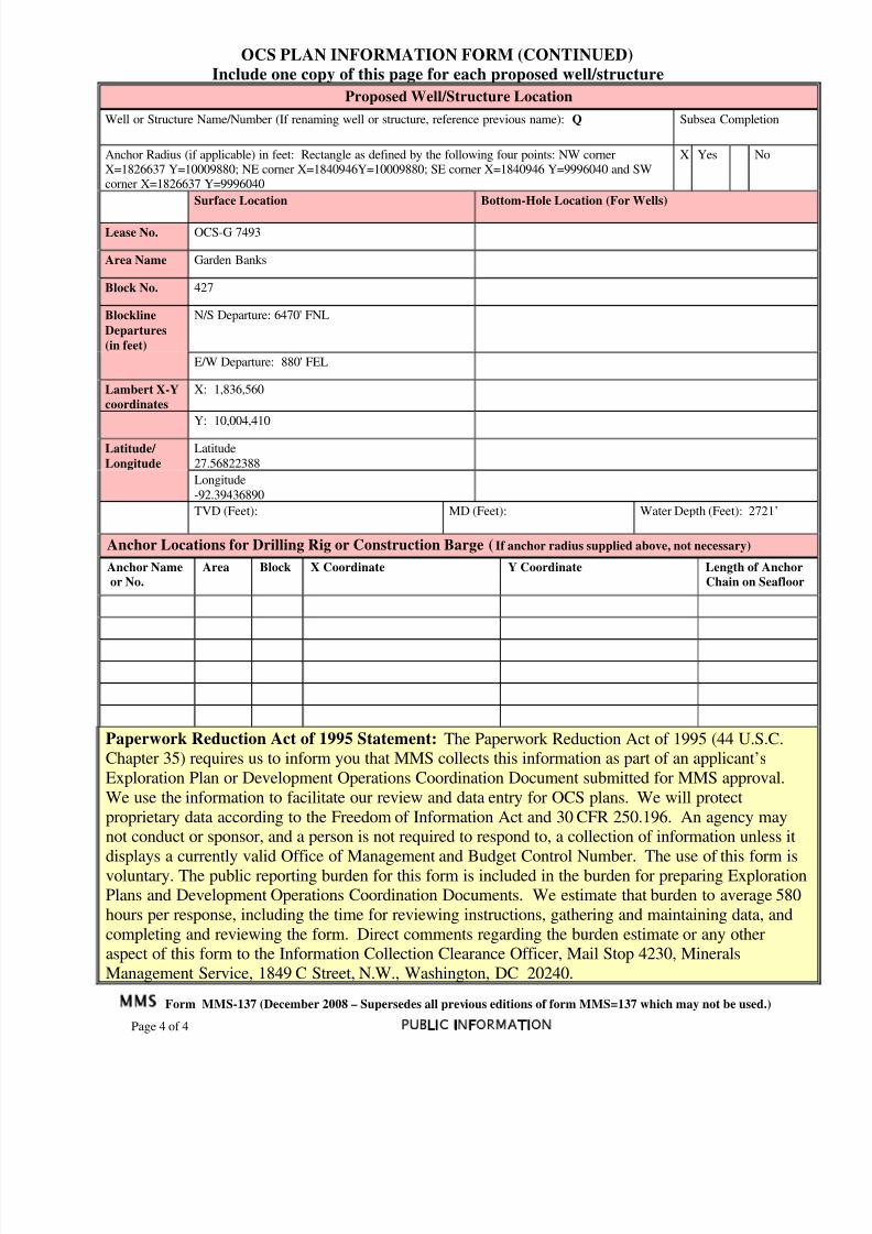
OCS PLAN INFORMATION FORM (CONTINUED)
Include one copy of this page for each proposed well/structure
Proposed Well/Structure Location
Well or Structure Name/Number (If renaming well or structure, reference previous name): O Subsea Completion
Anchor Radius (if applicable) in feet: Rectangle as defined by the following four points: NW cornerX=1826637 Y=10009880; NE corner X=1840946Y=10009880; SE corner X=1840946 Y=9996040 and SWcorner X=1826637 Y=9996040
X Yes No
Surface Location Bottom-Hole Location (For Wells)
Lease No. OCS-G 7493
Area Name Garden Banks
Block No. 427
Blockline
Departures
(in feet)
N/S Departure: 5965' FNL
E/W Departure: 1400' FEL
Lambert X-Y
coordinates
X: 1,836,040
Y: 10,004,915
Latitude/
Longitude
Latitude
27.56962046
Longitude
-92.39596682
TVD (Feet): MD (Feet): Water Depth (Feet): 2721’
Anchor Locations for Drilling Rig or Construction Barge (If anchor radius supplied above, not necessary)
Anchor Name
or No.
Area Block X Coordinate Y Coordinate Length of Anchor
Chain on Seafloor
Paperwork Reduction Act of 1995 Statement: The Paperwork Reduction Act of 1995 (44 U.S.C.
Chapter 35) requires us to inform you that MMS collects this information as part of an applicant’s
Exploration Plan or Development Operations Coordination Document submitted for MMS approval.We use the information to facilitate our review and data entry for OCS plans. We will protect
proprietary data according to the Freedom of Information Act and 30 CFR 250.196. An agency may
not conduct or sponsor, and a person is not required to respond to, a collection of information unless itdisplays a currently valid Office of Management and Budget Control Number. The use of this form is
voluntary. The public reporting burden for this form is included in the burden for preparing Exploration
Plans and Development Operations Coordination Documents. We estimate that burden to average 580
hours per response, including the time for reviewing instructions, gathering and maintaining data, andcompleting and reviewing the form. Direct comments regarding the burden estimate or any other
aspect of this form to the Information Collection Clearance Officer, Mail Stop 4230, MineralsManagement Service, 1849 C Street, N.W., Washington, DC 20240.
MMS Form MMS-137 (December 2008 – Supersedes all previous editions of form MMS=137 which may not be used.)
Page 2 of 4 PUBLIC INFORMATION
8/7/2019 Shell exploration plan
http://slidepdf.com/reader/full/shell-exploration-plan 5/48
OCS PLAN INFORMATION FORM (CONTINUED)
Include one copy of this page for each proposed well/structure
Proposed Well/Structure Location
Well or Structure Name/Number (If renaming well or structure, reference previous name): P Subsea Completion
Anchor Radius (if applicable) in feet: 4802’ Anchor Radius (if applicable) in feet: Rectangle as defined bythe following four points: NW corner X=1826637 Y=10009880; NE corner X=1840946Y=10009880; SEcorner X=1840946 Y=9996040 and SW corner X=1826637 Y=9996040
X Yes No
Surface Location Bottom-Hole Location (For Wells)
Lease No. OCS-G 7493
Area Name Garden Banks
Block No. 427
Blockline
Departures
(in feet)
N/S Departure: 5470' FNL
E/W Departure: 1920' FEL
Lambert X-Y
coordinates
X: 1,835,520
Y: 10,005,410
Latitude/
Longitude
Latitude
27.57098950
Longitude
-92.39756494
TVD (Feet): MD (Feet): Water Depth (Feet): 2721’
Anchor Locations for Drilling Rig or Construction Barge (If anchor radius supplied above, not necessary)
Anchor Name
or No.
Area Block X Coordinate Y Coordinate Length of Anchor
Chain on Seafloor
Paperwork Reduction Act of 1995 Statement: The Paperwork Reduction Act of 1995 (44 U.S.C.Chapter 35) requires us to inform you that MMS collects this information as part of an applicant’s
Exploration Plan or Development Operations Coordination Document submitted for MMS approval.
We use the information to facilitate our review and data entry for OCS plans. We will protect
proprietary data according to the Freedom of Information Act and 30 CFR 250.196. An agency maynot conduct or sponsor, and a person is not required to respond to, a collection of information unless it
displays a currently valid Office of Management and Budget Control Number. The use of this form isvoluntary. The public reporting burden for this form is included in the burden for preparing ExplorationPlans and Development Operations Coordination Documents. We estimate that burden to average 580
hours per response, including the time for reviewing instructions, gathering and maintaining data, and
completing and reviewing the form. Direct comments regarding the burden estimate or any otheraspect of this form to the Information Collection Clearance Officer, Mail Stop 4230, Minerals
Management Service, 1849 C Street, N.W., Washington, DC 20240.
MMS Form MMS-137 (December 2008 – Supersedes all previous editions of form MMS=137 which may not be used.)
Page 3 of 4 PUBLIC INFORMATION
8/7/2019 Shell exploration plan
http://slidepdf.com/reader/full/shell-exploration-plan 6/48
OCS PLAN INFORMATION FORM (CONTINUED)
Include one copy of this page for each proposed well/structure
Proposed Well/Structure Location
Well or Structure Name/Number (If renaming well or structure, reference previous name): Q Subsea Completion
Anchor Radius (if applicable) in feet: Rectangle as defined by the following four points: NW cornerX=1826637 Y=10009880; NE corner X=1840946Y=10009880; SE corner X=1840946 Y=9996040 and SWcorner X=1826637 Y=9996040
X Yes No
Surface Location Bottom-Hole Location (For Wells)
Lease No. OCS-G 7493
Area Name Garden Banks
Block No. 427
Blockline
Departures
(in feet)
N/S Departure: 6470' FNL
E/W Departure: 880' FEL
Lambert X-Y
coordinates
X: 1,836,560
Y: 10,004,410
Latitude/
Longitude
Latitude
27.56822388
Longitude
-92.39436890
TVD (Feet): MD (Feet): Water Depth (Feet): 2721’
Anchor Locations for Drilling Rig or Construction Barge (If anchor radius supplied above, not necessary)
Anchor Name
or No.
Area Block X Coordinate Y Coordinate Length of Anchor
Chain on Seafloor
Paperwork Reduction Act of 1995 Statement: The Paperwork Reduction Act of 1995 (44 U.S.C.Chapter 35) requires us to inform you that MMS collects this information as part of an applicant’s
Exploration Plan or Development Operations Coordination Document submitted for MMS approval.
We use the information to facilitate our review and data entry for OCS plans. We will protect
proprietary data according to the Freedom of Information Act and 30 CFR 250.196. An agency maynot conduct or sponsor, and a person is not required to respond to, a collection of information unless it
displays a currently valid Office of Management and Budget Control Number. The use of this form isvoluntary. The public reporting burden for this form is included in the burden for preparing ExplorationPlans and Development Operations Coordination Documents. We estimate that burden to average 580
hours per response, including the time for reviewing instructions, gathering and maintaining data, and
completing and reviewing the form. Direct comments regarding the burden estimate or any otheraspect of this form to the Information Collection Clearance Officer, Mail Stop 4230, Minerals
Management Service, 1849 C Street, N.W., Washington, DC 20240.
MMS Form MMS-137 (December 2008 – Supersedes all previous editions of form MMS=137 which may not be used.)
Page 4 of 4 PUBLIC INFORMATION

8/7/2019 Shell exploration plan
http://slidepdf.com/reader/full/shell-exploration-plan 7/48
(2j) Blowout scenario
Summary
This Section was prepared by Shell Offshore Inc. (Shell) pursuant to the guidance provided in the
Bureau of Ocean Energy Management, Regulation and Enforcement’s (BOEMRE) Notice toLessees (NTL) No. 2010-N06 with respect to blowout and worst case discharge scenario
descriptions.
Shell focuses on an integrated, three-pronged approach to a loss of well control event (blowout),
including prevention, intervention /containment, and recovery. Shell believes that the best way to
manage blowouts is to prevent them from happening. Significant effort goes into the design and
execution of wells and into building and maintaining staff competence with the goal of safe and
environmentally sound well construction. Shell continues to invest independently in Research and
Development (R&D) to improve safety and reliability of our well systems. Shell intends to complywith all applicable laws, regulations, rules and Notice to Lessees.
Shell is a founding member of the Marine Well Containment Corporation (MWCC) and will haveaccess to an integrated subsea well control and containment system that can be rapidly deployed
through the MWCC. The MWCC is a non-profit organization that owns, manages, and provides
fully trained crews to provide operational guidance of the subsea containment system during a
response. The near term containment response capability will be addressed in Shell’s NTL10submission at the time an Application to Drill (APD) is submitted and will include lessons learned
from the Macondo response. Shell is investing in R&D to improve containment systems. Also,
Shell is a member of Clean Caribbean America (CCA), Marine Spill Response Corporation
(MSRC), Clean Gulf Associates (CGA), and Oil Spill Response (OSR) to provide the resources
necessary to respond to a spill as outlined in our Regional Oil Spill Response Plan.
The Worst Case Discharge (WCD) blowout scenario for this EP is calculated for the GB 427 O
location and based on the guidelines outlined in NTL No. 2010-N06 along with subsequent
Frequently Asked Questions (FAQ). The WCD for GB 427 O falls below the WCD exploratory
scenario (MC 391) included in our Regional OSRP. In the unlikely event of a spill, Shell’s RegionalOSRP (October 2010) is designed to contain and respond to a spill that meets or exceeds this WCD.The WCD does not take into account potential flow mitigating factors such as well bridging,
obstructions in wellbore, reservoir barriers, or early intervention.
Uncontrolled blowout (volume first day) 184,000 bbl
Uncontrolled blowout rate (first 30-days average daily rate) 166,000 bopdDuration of flow (days) based on relief well 109 days
Total volume of spill (bbls) for 109 days 14.4 MMBO
Table 1 Worst Case Discharge Summary
8/7/2019 Shell exploration plan
http://slidepdf.com/reader/full/shell-exploration-plan 8/48
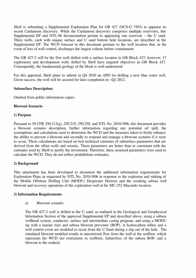
Shell is submitting a Supplemental Exploration Plan for GB 427 (OCS-G 7493) to appraise itsrecent Cardamom discovery. While the Cardamom discovery comprises multiple reservoirs, thisSupplemental EP and NTL-06 documentation pertain to appraising one reservoir – the U sand.Three wells, each with unique surface and U sand bottom hole locations, are described in the
Supplemental EP. The WCD forecast in this document pertains to the well location that, in the
event of loss of well control, discharges the largest volume before containment.
The GB 427-2 will be the first well drilled with a surface location in GB Block 427; however, 17
exploratory and development wells drilled by Shell have targeted objectives in GB Block 427.Consequently, the fundamental geology of the block is well understood.
For this appraisal, Shell plans to submit in Q4 2010 an APD for drilling a new blue water well.
Given success, the well will be secured for later completion in ~Q2 2012.
Subsurface Description:
Omitted from public information copies
Blowout Scenario
1) Purpose
Pursuant to 30 CFR 250.213(g), 250.219, 250.250, and NTL No. 2010-N06, this document provides
a blowout scenario description, further information regarding any potential oil spill, the
assumptions and calculations used to determine the WCD and the measures taken to firstly enhance
the ability to prevent a blowout and secondly to respond and manage a blowout scenario if it were
to occur. These calculations are based on best technical estimates of subsurface parameters that are
derived from the offset wells and seismic. These parameters are better than or consistent with theestimates used by Shell to justify the investment. Therefore, these assumed parameters were used to
calculate the WCD. They do not reflect probabilistic estimates.
2) Background
This attachment has been developed to document the additional information requirements forExploration Plans as requested by NTL No. 2010-N06 in response to the explosion and sinking of
the Mobile Offshore Drilling Unit (MODU) Deepwater Horizon and the resulting subsea well
blowout and recovery operations of the exploration well at the MC-252 Macondo location.
3) Information Requirements
a) Blowout scenario
The GB 427-2 well is drilled to the U sand, as outlined in the Geological and Geophysical
Information Section of the approved Supplemental EP and described above, using a subsea
wellhead system, conductor, surface and intermediate casing program, and using a MODU
rig with a marine riser and subsea blowout preventer (BOP). A hydrocarbon influx and a
well control event are modeled to occur from the U Sand during a trip out of the hole. Thesimulated blowout modeled results in unrestricted flow from the well at the seafloor, whichrepresents the WCD (no restrictions in wellbore, failure/loss of the subsea BOP, and a
blowout to the seabed).

8/7/2019 Shell exploration plan
http://slidepdf.com/reader/full/shell-exploration-plan 9/48
b) Estimated flow rate of the potential blowout
Category Initial EP
Type of Activity Drilling
Facility Location (area/block) GB-427
Facility Designation MODU
Distance to Nearest Shoreline (miles) 130 miles
Uncontrolled blowout (volume first day) 184,000 bbl
Uncontrolled blowout rate (first 30-days average daily rate) 166,000 bopd
Table 2 Estimated Flow Rates of a Potential Blowout
c) Total volume and maximum duration of the potential blowout
Duration of flow (days) 109 days total duration(14 days to contract/mob rig 95
days to drill relief well)
Total volume of spill (bbls) 14.4 MMBONote: based on MBAL Material
balance reservoir model *
* Note: The U sand model was constructed using observations from analogue fields in the
area which indicate that moderate aquifer support is likely. Model and model outputs can be
provided to the BOEMRE in electronic form upon request.
Table 3 Estimated Duration and Volume of a Potential Blowout
d) Assumptions and calculations used in determining the worst case discharge
Information omitted from public information copies.
The NTL 2010-06 Worst Case Blowout requirements for our Regional Oil Spill Response Planhighest exploration well, were previously submitted October 26, 2010 with our SupplementalExploration Plan for Mississippi Canyon Blocks 391, 392 and 348, Plan Control No. R-5066.

8/7/2019 Shell exploration plan
http://slidepdf.com/reader/full/shell-exploration-plan 10/48
(3f) Shallow Hazards Assessment
SITE SPECIFIC COMMENTS
History
Shell’s Auger TLP is centered in GB426 at X = 1,820,750 Y= 9,996,240. The anchors for the TLP
extend into blocks 426 and 427. Two of the lateral mooring anchors are within the requested
anchor pattern radius. None of the Auger Platform wells have surface locations in block 427. Shellnow seeks approval to use the anchored vessel Noble Jim Thompson or similar rig within a
rectangle with coordinates of: NW corner X=1826637 Y=10009880; NE corner
X=1840946Y=10009880; SE corner X=1840946 Y=9996040 and SW corner X=1826637
Y=9996040 with a 1000’ buffer to perform its planned operations on proposed locations O, P, and
Q. Within this area there are two Auger Lateral mooring system lines:
C1A-L1 is located at X = 1,826,623 Y = 10,003,220
C1A-L2 is located at X = 1,829,722 Y = 9,997,196
Flowlines flank the Auger dome on all sides. Existing pipelines surround and cross the proposed
radius. Shell will maintain a buffer of at least 500’ when setting anchors. Shell will not set anchors
at the intersection of the pipelines.
To assess the proposed anchor radius and surrounding area, Shell used the following data:
- Fugro-McClelland Anchoring Report Proposed Tension Leg Platform and M/V George
Richardson for GB 426, 427, 470 and 471 dated February 22, 1990
- Fugro’s Archeological Assessment Garden Banks Block 427 Report 2410-1061 dated May
2010 (based on Fugro report No. 0201-0526)- Chance’s Hazard Study of GB 426, 427, 470, and 471 dated September 1985,
- C& C Technologies Engineering and Hazard Study for 10” x 6” Pipeline Route in GB 341
to 426, Report No. 3566-3662 dated March 2003
- C& C Technologies Engineering and Hazard Study for 12” x 8” Pipeline Route in GB 341
to 426, Report No. 3567-3663 dated June 2003- Shell’s high resolution 3-D surveys
Well Locations Information
The proposed locations will use a 4,802’ (plus 1000’ buffer) radius. The rig center will be
X = 1,836,144 Y = 10,004,512
The well centers are:
Proposed Location O: X = 1836040 Y = 10004915
Proposed Location P: X = 1835520 Y = 10005410
Proposed Location Q: X = 1836560 Y = 10004410
Based on a high-resolution geophysical survey consisting of frequency enhanced 3-D seismic,
Enhanced Surface Renderings, and Enhanced Surface Renderings with amplitudes applied, deep-tow data, Archeological Assessment, side scan sonar, and Subbottom profiler data, the plannedanchoring operations for GB 427 are suitable for the planned activities.
David Garner Vernessa Bradford
Staff Geological Engineer Shallow Hazards Interpreter
8/7/2019 Shell exploration plan
http://slidepdf.com/reader/full/shell-exploration-plan 11/48
6 Biological, Physical, and Socioeconomic Information
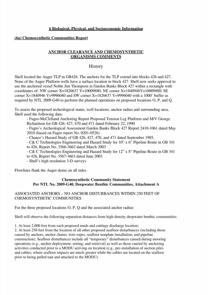
(6a) Chemosynthetic Communities Report
ANCHOR CLEARANCE AND CHEMOSYNTHETICORGANISMS COMMENTS
History
Shell located the Auger TLP in GB426. The anchors for the TLP extend into blocks 426 and 427.
None of the Auger Platform wells have a surface location in block 427. Shell now seeks approval touse the anchored vessel Noble Jim Thompson in Garden Banks Block 427 within a rectangle with
coordinates of: NW corner X=1826637 Y=10009880; NE corner X=1840946Y=10009880; SE
corner X=1840946 Y=9996040 and SW corner X=1826637 Y=9996040 with a 1000’ buffer as
required by NTL 2009-G40 to perform the planned operations on proposed locations O, P, and Q.
To assess the proposed archeological status, well locations, anchor radius and surrounding area,
Shell used the following data:- Fugro-McClelland Anchoring Report Proposed Tension Leg Platform and M/V George
Richardson for GB 426, 427, 470 and 471 dated February 22, 1990
- Fugro’s Archeological Assessment Garden Banks Block 427 Report 2410-1061 dated May
2010 (based on Fugro report No. 0201-0526)
- Chance’s Hazard Study of GB 426, 427, 470, and 471 dated September 1985,
- C& C Technologies Engineering and Hazard Study for 10” x 6” Pipeline Route in GB 341to 426, Report No. 3566-3662 dated March 2003
- C& C Technologies Engineering and Hazard Study for 12” x 8” Pipeline Route in GB 341
to 426, Report No. 3567-3663 dated June 2003- Shell’s high resolution 3-D surveys
Flowlines flank the Auger dome on all sides.
Chemosynthetic Community Statement
Per NTL No. 2009-G40, Deepwater Benthic Communities, Attachment A
ASSOCIATED ANCHORS – NO ANCHOR DISTURBANCES WITHIN 250 FEET OF
CHEMOSYNTHETIC COMMUNITIES
For the three proposed locations O, P, Q and the associated anchor radius:
Shell will observe the following separation distances from high-density deepwater benthic communities:
1. At least 2,000 feet from each proposed muds and cuttings discharge location;
2. At least 250 feet from the location of all other proposed seafloor disturbances (including those
caused by anchors, anchor chains, wire ropes, seafloor template installation, and pipeline
construction). Seafloor disturbances include all “temporary” disturbances caused during mooring
operations (e.g., anchor deployment, setting, and retrieval) as well as those caused by anchoring
activities conducted prior to a MODU arriving on location (e.g., pre-installation of suction piles
and cables; where seafloor impacts are much greater while the cables are located on the seafloor
prior to being pulled taut and attached to the MODU).`

8/7/2019 Shell exploration plan
http://slidepdf.com/reader/full/shell-exploration-plan 12/48
Anchor Pattern Analysis
The proposed rectangular “radius” has the following coordinates: NW corner X=1826637Y=10009880; NE corner X=1840946 Y=10009880; SE corner X=1840946 Y=9996040 and SW
corner X=1826637 Y=9996040.
The center of the rig will be X = 1,836,144 Y = 10,004,512.
The proposed well centers are:
Proposed Location O: X = 1836040 Y = 10004915
Proposed Location P: X = 1835520 Y = 10005410
Proposed Location Q: X = 1836560 Y = 10004410
The seafloor east of the diapir is relatively smooth. The proposed locations are east of the base of the Auger diaper in GB427. There are four amplitudes and fluid expulsion features on its crest.
From left to right, their center coordinates are:
1 X = 1828115.61 Y = 10001005.83
2 X = 1829096.38 Y = 10001119.85
3 X = 1830134.70 Y = 10002291.81
4 X = 1830808.04 Y = 10002577.53
Shell has designated a 250’ avoidance zone around each fluid expulsion feature. Outside these
avoidance zones, the subsurface has a dark reflectivity, interpreted as authigenic. The Auger dome
has numerous seafloor faults that radiate from its crest. The faults also curve
around the perimeter of the dome. These faults are usually small displacements affecting the
shallow sediments and the seafloor. Vertical displacement of the subsurface reflectors was generallyless than 10 feet and seafloor displacement is less than 5 feet. Because of these conditions, the
placement of the suction anchors will be optimized. The suction anchors will be located to
minimize penetration of shallow seafloor faults on the eastern side of the dome.
Shell will set the anchors using ROV to survey the area before installation.
The Auger Lateral Mooring System has two lines within the proposed area. The coordinates are:
Auger Lateral Line 3: X = 1826896.33 Y = 10003502.30
Auger Lateral Line 4: X = 1830117.92 Y = 9997246.92
Shell will observe an anchor/suction buffer of 500’ from these lines.
Archeological AssessmentPer the archeological report, there are items of modern drilling debris such as drill pipe on the
seafloor. One item is an unidentified contact measuring 25’ long by 25’ wide. This contact is a mud
mat associated with former construction, shipping, or fishing activities. Its location is
approximately X = 1822600; Y = 9995240. Previously drilled GB 471 Well # 1 is located at
X = 1823472; Y = 9994628. The mud mat and the well are outside the proposed radius.
There are no landforms or identified features that might be high probability prehistoric sites, such asnatural levees or point bar deposits. The regional probability for historic shipwrecks in this area islow.
8/7/2019 Shell exploration plan
http://slidepdf.com/reader/full/shell-exploration-plan 13/48
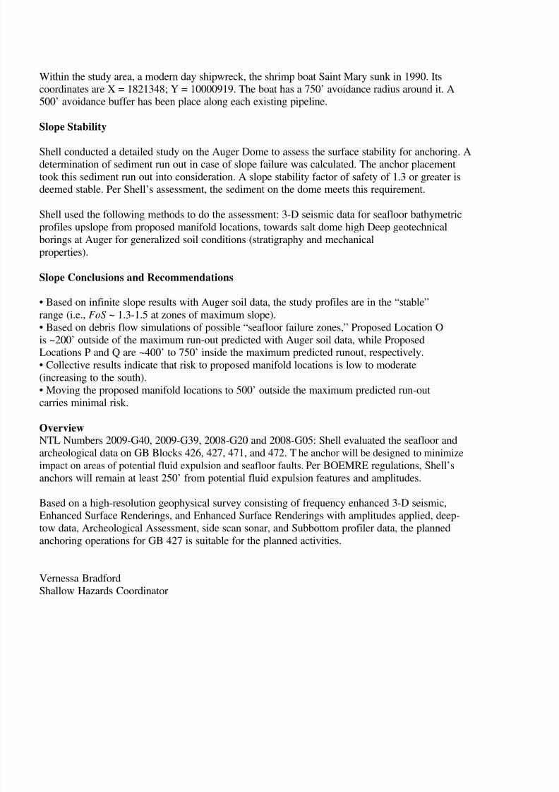
Within the study area, a modern day shipwreck, the shrimp boat Saint Mary sunk in 1990. Itscoordinates are X = 1821348; Y = 10000919. The boat has a 750’ avoidance radius around it. A500’ avoidance buffer has been place along each existing pipeline.
Slope Stability
Shell conducted a detailed study on the Auger Dome to assess the surface stability for anchoring. A
determination of sediment run out in case of slope failure was calculated. The anchor placement
took this sediment run out into consideration. A slope stability factor of safety of 1.3 or greater isdeemed stable. Per Shell’s assessment, the sediment on the dome meets this requirement.
Shell used the following methods to do the assessment: 3-D seismic data for seafloor bathymetric
profiles upslope from proposed manifold locations, towards salt dome high Deep geotechnical
borings at Auger for generalized soil conditions (stratigraphy and mechanical
properties).
Slope Conclusions and Recommendations
• Based on infinite slope results with Auger soil data, the study profiles are in the “stable”
range (i.e., FoS ~ 1.3-1.5 at zones of maximum slope).
• Based on debris flow simulations of possible “seafloor failure zones,” Proposed Location O
is ~200’ outside of the maximum run-out predicted with Auger soil data, while ProposedLocations P and Q are ~400’ to 750’ inside the maximum predicted runout, respectively.
• Collective results indicate that risk to proposed manifold locations is low to moderate
(increasing to the south).
• Moving the proposed manifold locations to 500’ outside the maximum predicted run-out
carries minimal risk.
OverviewNTL Numbers 2009-G40, 2009-G39, 2008-G20 and 2008-G05: Shell evaluated the seafloor and
archeological data on GB Blocks 426, 427, 471, and 472. The anchor will be designed to minimize
impact on areas of potential fluid expulsion and seafloor faults. Per BOEMRE regulations, Shell’s
anchors will remain at least 250’ from potential fluid expulsion features and amplitudes.
Based on a high-resolution geophysical survey consisting of frequency enhanced 3-D seismic,
Enhanced Surface Renderings, and Enhanced Surface Renderings with amplitudes applied, deep-
tow data, Archeological Assessment, side scan sonar, and Subbottom profiler data, the planned
anchoring operations for GB 427 is suitable for the planned activities.
Vernessa Bradford
Shallow Hazards Coordinator

8/7/2019 Shell exploration plan
http://slidepdf.com/reader/full/shell-exploration-plan 14/48

8/7/2019 Shell exploration plan
http://slidepdf.com/reader/full/shell-exploration-plan 15/48
Supplemental Exploration Plan
OCS-G 7493, Garden Banks Block 427
Garden Banks 471 Unit
Offshore, Louisiana
8 AIR EMISSIONS INFORMATION
(8a) Emissions Worksheet and Screening Questions
Screening Questions for EP’s Yes No
Is any calculated Complex Total (CT) Emission amount (in tons) associated with
your proposed exploration activities more than 90% of the amounts calculated
using the following formulas: CT = 3400D2/3
for CO, and CT 33.3D for theother air pollutants (where D distance to shore in miles)?
x
Do your emission calculations include any emission reduction measures ormodified emission factors? x
Are your proposed exploration activities located east of 87.5° W longitude?x
Do you expect to encounter H2S at concentrations greater than 20 parts per million
(ppm)? x
Do you propose to flare or vent natural gas for more than 48 continuous hours
From any proposed well? x
Do you propose to burn produced hydrocarbon liquids? x
(8b) If you answer no to all of the above screening questions from the appropriate table, provide:
(1) Summary information regarding the peak year emissions for both Plan Emissions and Complex
Total Emissions, if applicable. This information is compiled on the summary form of the two sets of
worksheets. You can submit either these summary forms or use the format below. You do not need
to include the entire set of worksheets.
Air Pollutant Plan
Emission1
Amounts
(tons)
Calculated
Exemption2
Amounts
(tons)
Calculated
Complex Total
Emission
Amounts3
(tons)
PM 17.36 4329 17.36
SOx 98.91 4329 98.91
NOx 742.18 4329 742.18
VOC 23.44 4329 23.44CO 161.89 87251.82 161.89
1For activities proposed in your EP or DOCD, list the projected emissions calculated from the worksheets.
2List the exemption amounts for your proposed ac tivities calculated by using the formulas in 30 CFR 250.303(d).
3List the complex total emissions associated with your proposed activities calculated from the worksheets
(2) Contact: Sylvia Bellone, (504) 728-7215, Sylvia.Bellone@ shell.com
(1) Worksheets
Because the answers to all the questions set forth above is “no”, further worksheets are not required.
8/7/2019 Shell exploration plan
http://slidepdf.com/reader/full/shell-exploration-plan 16/48
Supplemental Exploration Plan
OCS-G 7493, Garden Banks Block 427
Garden Banks 471 Unit
Offshore, Louisiana
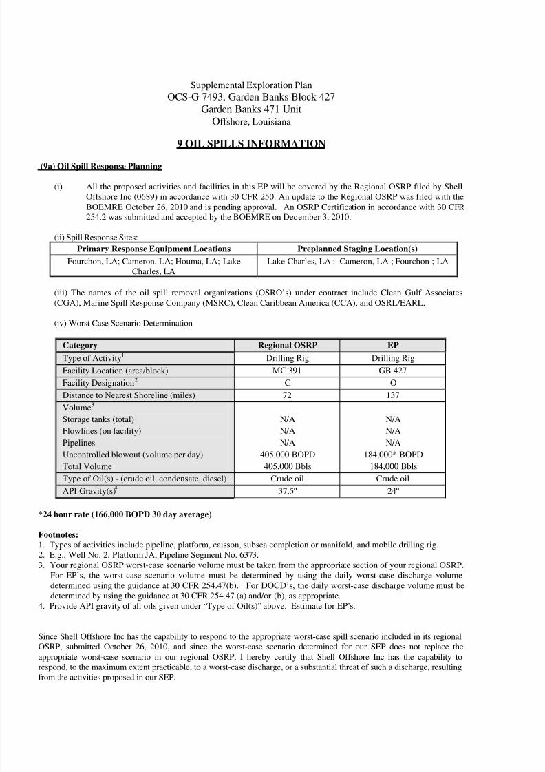
9 OIL SPILLS INFORMATION
(9a) Oil Spill Response Planning
(i) All the proposed activities and facilities in this EP will be covered by the Regional OSRP filed by Shell
Offshore Inc (0689) in accordance with 30 CFR 250. An update to the Regional OSRP was filed with the
BOEMRE October 26, 2010 and is pending approval. An OSRP Certification in accordance with 30 CFR254.2 was submitted and accepted by the BOEMRE on December 3, 2010.
(ii) Spill Response Sites:
Primary Response Equipment Locations Preplanned Staging Location(s)
Fourchon, LA; Cameron, LA; Houma, LA; Lake
Charles, LA
Lake Charles, LA ; Cameron, LA ; Fourchon ; LA
(iii) The names of the oil spill removal organizations (OSRO’s) under contract include Clean Gulf Associates
(CGA), Marine Spill Response Company (MSRC), Clean Caribbean America (CCA), and OSRL/EARL.
(iv) Worst Case Scenario Determination
Category Regional OSRP EP
Type of Activity1
Drilling Rig Drilling Rig
Facility Location (area/block) MC 391 GB 427
Facility Designation2 C O
Distance to Nearest Shoreline (miles) 72 137
Volume3
Storage tanks (total)
Flowlines (on facility)
Pipelines
Uncontrolled blowout (volume per day)
Total Volume
N/A
N/A
N/A
405,000 BOPD
405,000 Bbls
N/A
N/A
N/A
184,000* BOPD
184,000 Bbls
Type of Oil(s) - (crude oil, condensate, diesel) Crude oil Crude oil
API Gravity(s) 37.5º 24º
*24 hour rate (166,000 BOPD 30 day average)
Footnotes:1. Types of activities include pipeline, platform, caisson, subsea completion or manifold, and mobile drilling rig.
2. E.g., Well No. 2, Platform JA, Pipeline Segment No. 6373.
3. Your regional OSRP worst-case scenario volume must be taken from the appropriate section of your regional OSRP.
For EP’s, the worst-case scenario volume must be determined by using the daily worst-case discharge volume
determined using the guidance at 30 CFR 254.47(b). For DOCD’s, the daily worst-case discharge volume must be
determined by using the guidance at 30 CFR 254.47 (a) and/or (b), as appropriate.
4. Provide API gravity of all oils given under “Type of Oil(s)” above. Estimate for EP’s.
Since Shell Offshore Inc has the capability to respond to the appropriate worst-case spill scenario included in its regional
OSRP, submitted October 26, 2010, and since the worst-case scenario determined for our SEP does not replace the
appropriate worst-case scenario in our regional OSRP, I hereby certify that Shell Offshore Inc has the capability to
respond, to the maximum extent practicable, to a worst-case discharge, or a substantial threat of such a discharge, resulting
from the activities proposed in our SEP.
8/7/2019 Shell exploration plan
http://slidepdf.com/reader/full/shell-exploration-plan 17/48
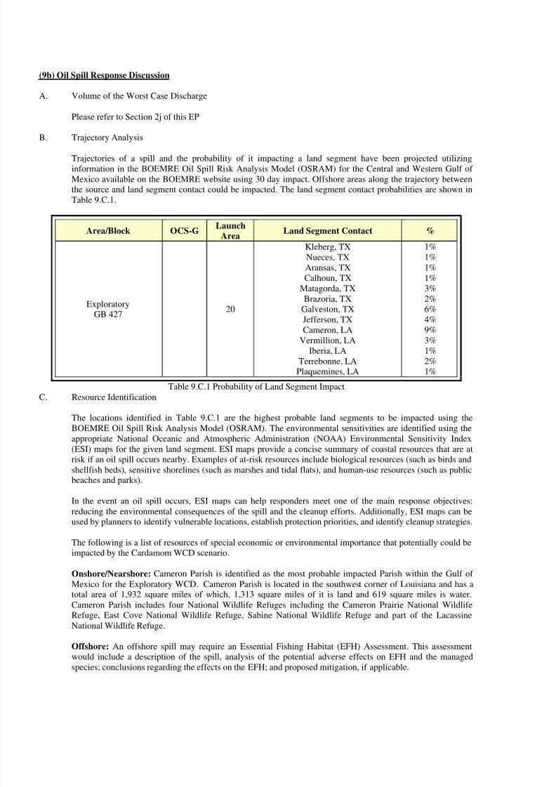
(9b) Oil Spill Response Discussion
A. Volume of the Worst Case Discharge
Please refer to Section 2j of this EP
B. Trajectory Analysis
Trajectories of a spill and the probability of it impacting a land segment have been projected utilizing
information in the BOEMRE Oil Spill Risk Analysis Model (OSRAM) for the Central and Western Gulf of
Mexico available on the BOEMRE website using 30 day impact. Offshore areas along the trajectory between
the source and land segment contact could be impacted. The land segment contact probabilities are shown in
Table 9.C.1.
Area/Block OCS-GLaunch
AreaLand Segment Contact %
ExploratoryGB 427
20
Kleberg, TX
Nueces, TX
Aransas, TX
Calhoun, TXMatagorda, TX
Brazoria, TX
Galveston, TX
Jefferson, TX
Cameron, LA
Vermillion, LA
Iberia, LA
Terrebonne, LA
Plaquemines, LA
1%
1%
1%
1%3%
2%
6%
4%
9%
3%
1%
2%
1%
Table 9.C.1 Probability of Land Segment Impact
C. Resource Identification
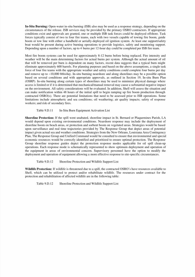
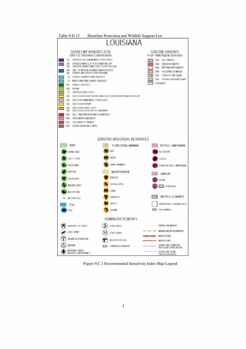
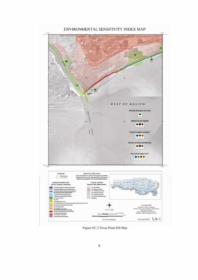
The locations identified in Table 9.C.1 are the highest probable land segments to be impacted using the
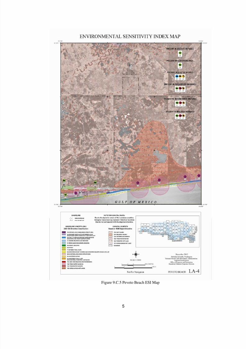
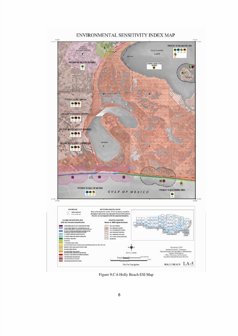
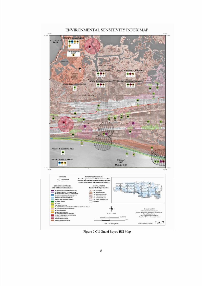
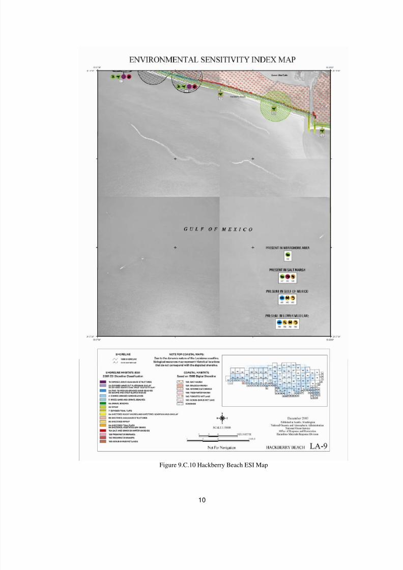
BOEMRE Oil Spill Risk Analysis Model (OSRAM). The environmental sensitivities are identified using the
appropriate National Oceanic and Atmospheric Administration (NOAA) Environmental Sensitivity Index
(ESI) maps for the given land segment. ESI maps provide a concise summary of coastal resources that are at
risk if an oil spill occurs nearby. Examples of at-risk resources include biological resources (such as birds and
shellfish beds), sensitive shorelines (such as marshes and tidal flats), and human-use resources (such as publicbeaches and parks).
In the event an oil spill occurs, ESI maps can help responders meet one of the main response objectives:
reducing the environmental consequences of the spill and the cleanup efforts. Additionally, ESI maps can be
used by planners to identify vulnerable locations, establish protection priorities, and identify cleanup strategies.
The following is a list of resources of special economic or environmental importance that potentially could be
impacted by the Cardamom WCD scenario.
Onshore/Nearshore: Cameron Parish is identified as the most probable impacted Parish within the Gulf of
Mexico for the Exploratory WCD. Cameron Parish is located in the southwest corner of Louisiana and has atotal area of 1,932 square miles of which, 1,313 square miles of it is land and 619 square miles is water.
Cameron Parish includes four National Wildlife Refuges including the Cameron Prairie National Wildlife
Refuge, East Cove National Wildlife Refuge, Sabine National Wildlife Refuge and part of the Lacassine
National Wildlife Refuge.
Offshore: An offshore spill may require an Essential Fishing Habitat (EFH) Assessment. This assessment
would include a description of the spill, analysis of the potential adverse effects on EFH and the managed
species; conclusions regarding the effects on the EFH; and proposed mitigation, if applicable.
8/7/2019 Shell exploration plan
http://slidepdf.com/reader/full/shell-exploration-plan 18/48
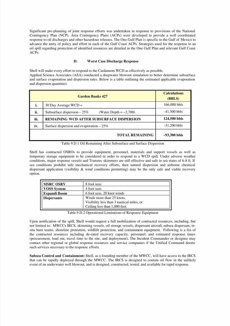
Significant pre-planning of joint response efforts was undertaken in response to provisions of the National
Contingency Plan (NCP). Area Contingency Plans (ACPs) were developed to provide a well coordinated
response to oil discharges and other hazardous releases. The One Gulf Plan is specific to the Gulf of Mexico to
advance the unity of policy and effort in each of the Gulf Coast ACPs. Strategies used for the response to an
oil spill regarding protection of identified resources are detailed in the One Gulf Plan and relevant Gulf Coast
ACPs.
D. Worst Case Discharge Response
Shell will make every effort to respond to the Cardamom WCD as effectively as possible.
Applied Science Associates (ASA) conducted a deepwater blowout simulation to better determine subsurface
and surface evaporation and dispersion rates. Below is a table outlining the estimated applicable evaporation
and dispersion quantities:
Garden Banks 427Calculations
(BBLS)
i. 30 Day Average WCD = 166,000 bbls
ii. Subsurface dispersion – 25% (Water Depth = ~2,700) -41,500 bbls
iii. REMAINING WCD AFTER SUBSURFACE DISPERSION 124,500 bbls
iv. Surface dispersion and evaporation – 25% -31,200 bbls
TOTAL REMAINING ~93,300 bbls
Table 9.D.1 Oil Remaining After Subsurface and Surface Dispersion
Shell has contracted OSROs to provide equipment, personnel, materials and support vessels as well as
temporary storage equipment to be considered in order to respond to a WCD spill. Under adverse weather
conditions, major response vessels and Transrec skimmers are still effective and safe in sea states of 6-8 ft. If
sea conditions prohibit safe mechanical recovery efforts, then natural dispersion and airborne chemical
dispersant application (visibility & wind conditions permitting) may be the only safe and viable recovery
option.
MSRC OSRV 8 foot seas
VOSS System 4 foot seas
Expandi Boom 6 foot seas, 20 knot winds
Dispersants Winds more than 25 knots,
Visibility less than 3 nautical miles, or
Ceiling less than 1,000 feet.
Table 9.D.2 Operational Limitations of Response Equipment
Upon notification of the spill, Shell would request a full mobilization of contracted resources, including, but
not limited to: MWCCs IRCS, skimming vessels, oil storage vessels, dispersant aircraft, subsea dispersant, in-
situ burn teams, shoreline protection, wildlife protection, and containment equipment. Following is a list of
the contracted resources including de-rated recovery capacity, personnel, and estimated response times
(procurement, load out, travel time to the site, and deployment). The Incident Commander or designee may
contact other regional or global response resources and service companies if the Unified Command deems
such services necessary to the response efforts.
Subsea Control and Containment: Shell, as a founding member of the MWCC, will have access to the IRCS
that can be rapidly deployed through the MWCC. The IRCS is designed to contain oil flow in the unlikely
event of an underwater well blowout, and is designed, constructed, tested, and available for rapid response.
8/7/2019 Shell exploration plan
http://slidepdf.com/reader/full/shell-exploration-plan 19/48
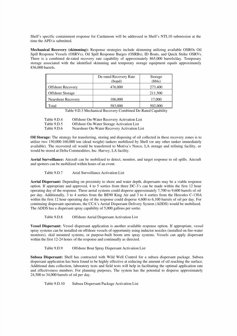
Shell’s specific containment response for Cardamom will be addressed in Shell’s NTL10 submission at the
time the APD is submitted.
Mechanical Recovery (skimming): Response strategies include skimming utilizing available OSROs Oil
Spill Response Vessels (OSRVs), Oil Spill Response Barges (OSRBs), ID Boats, and Quick Strike OSRVs.
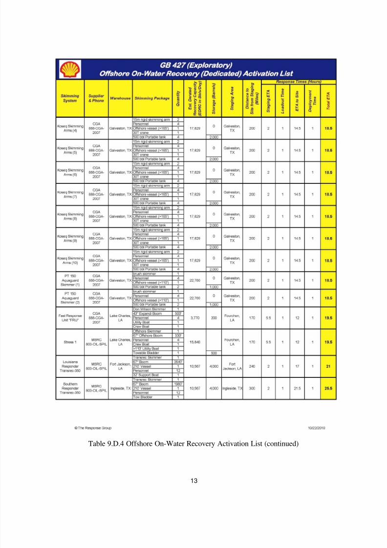
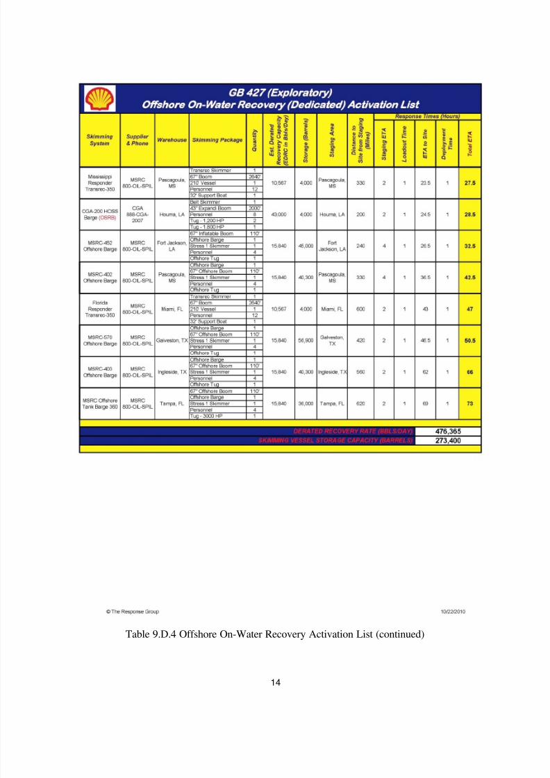
There is a combined de-rated recovery rate capability of approximately 865,000 barrels/day. Temporarystorage associated with the identified skimming and temporary storage equipment equals approximately
836,000 barrels.
De-rated Recovery Rate
(bopd)
Storage
(bbls)
Offshore Recovery 476,000 273,400
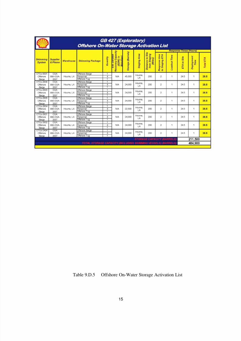
Offshore Storage 211,500
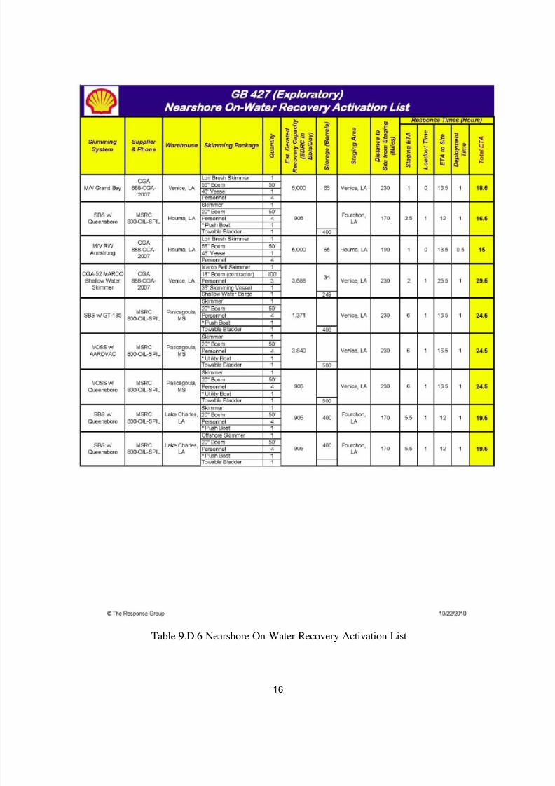
Nearshore Recovery 106,000 17,000
Total 583,000 502,000
Table 9.D.3 Mechanical Recovery Combined De-Rated Capability
Table 9.D.4 Offshore On-Water Recovery Activation List
Table 9.D.5 Offshore On-Water Storage Activation List
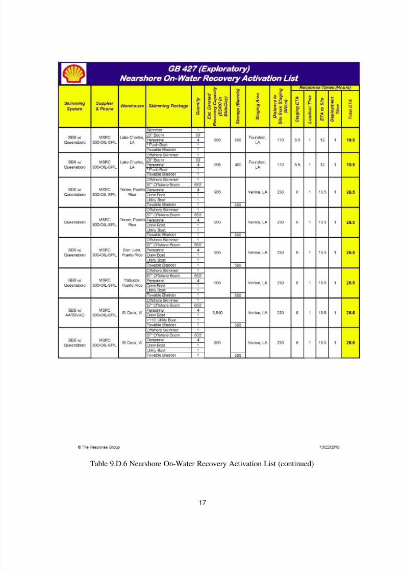
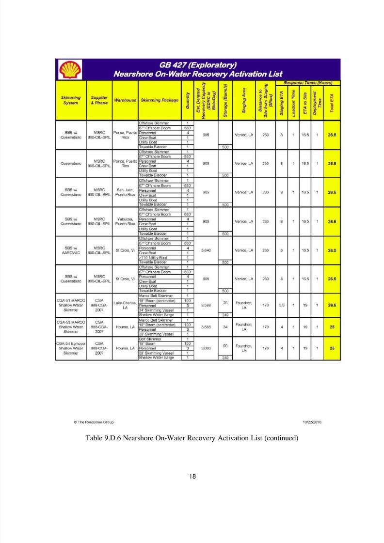
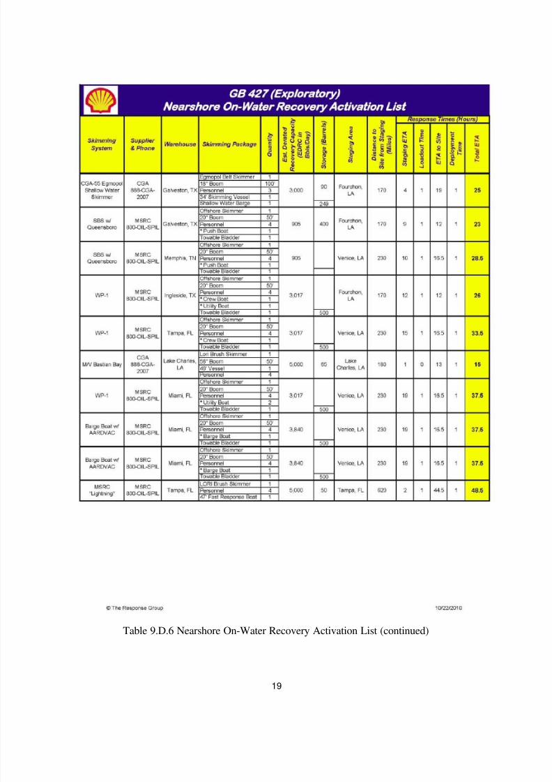
Table 9.D.6 Nearshore On-Water Recovery Activation List
Oil Storage: The strategy for transferring, storing and disposing of oil collected in these recovery zones is to
utilize two 150,000-160,000 ton (dead weight) tankers mobilized by Shell (or any other tanker immediately
available). The recovered oil would be transferred to Motiva’s Norco, LA storage and refining facility, or
would be stored at Delta Commodities, Inc. Harvey, LA facility.
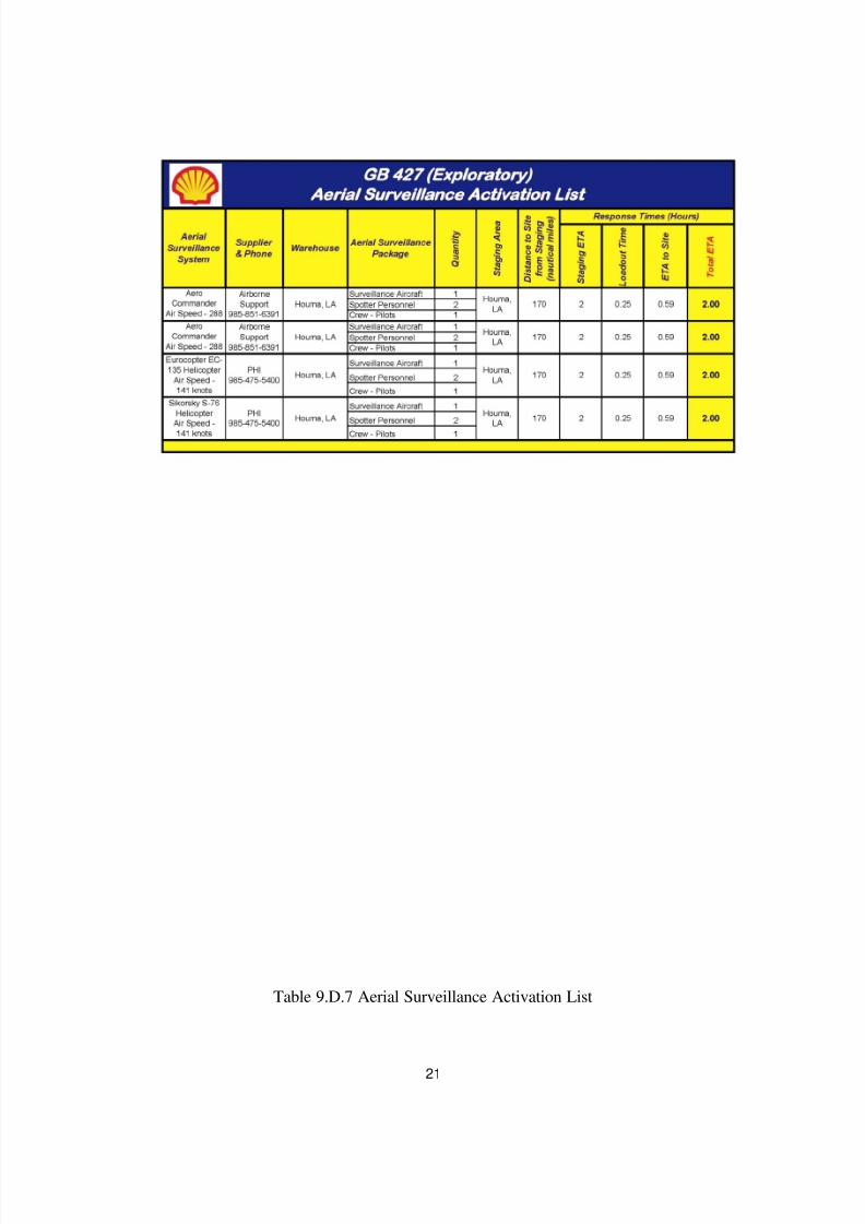
Aerial Surveillance: Aircraft can be mobilized to detect, monitor, and target response to oil spills. Aircraft
and spotters can be mobilized within hours of an event.
Table 9.D.7 Arial Surveillance Activation List
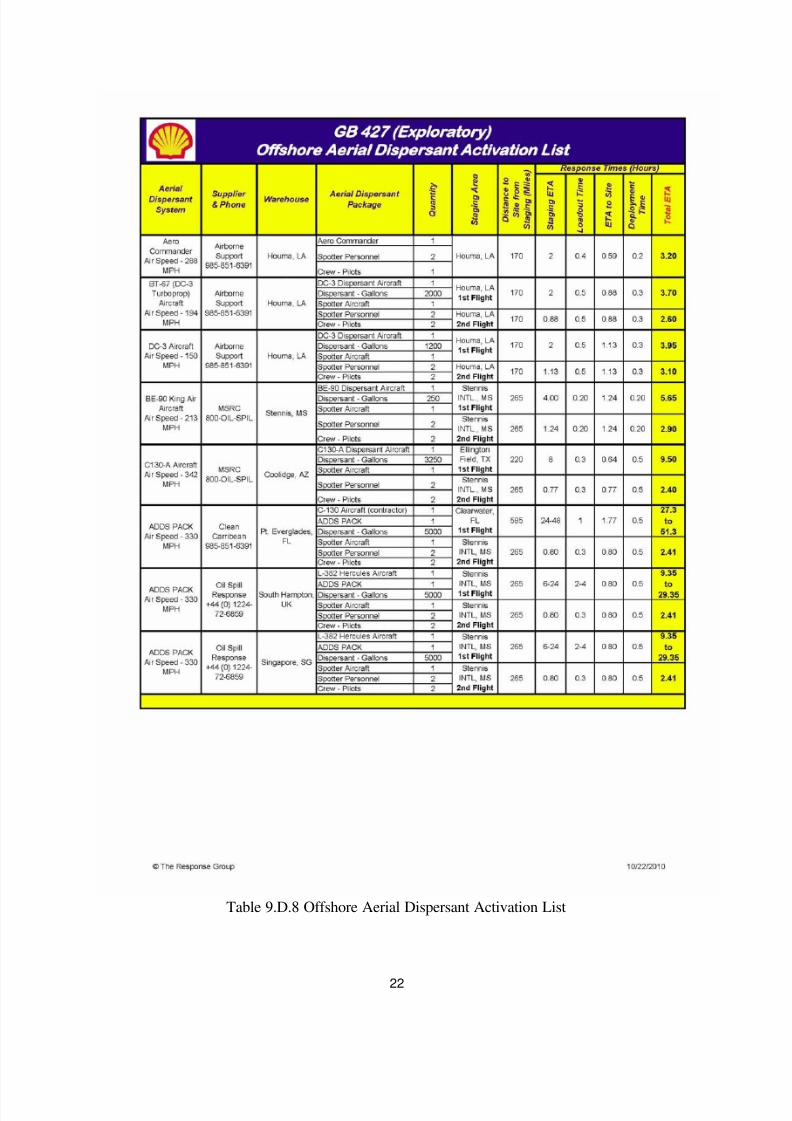
Aerial Dispersant: Depending on proximity to shore and water depth, dispersants may be a viable response
option. If appropriate and approved, 4 to 5 sorties from three DC-3’s can be made within the first 12 hour
operating day of the response. These aerial systems could disperse approximately 7,700 to 9,600 barrels of oil
per day. Additionally, 3 to 4 sorties from the BE90 King Air and 3 to 4 sorties from the Hercules C-130A
within the first 12 hour operating day of the response could disperse 4,600 to 6,100 barrels of oil per day. For
continuing dispersant operations, the CCA’s Aerial Dispersant Delivery System (ADDS) would be mobilized.
The ADDS has a dispersant spray capability of 5,000 gallons per sortie.
Table 9.D.8 Offshore Aerial Dispersant Activation List
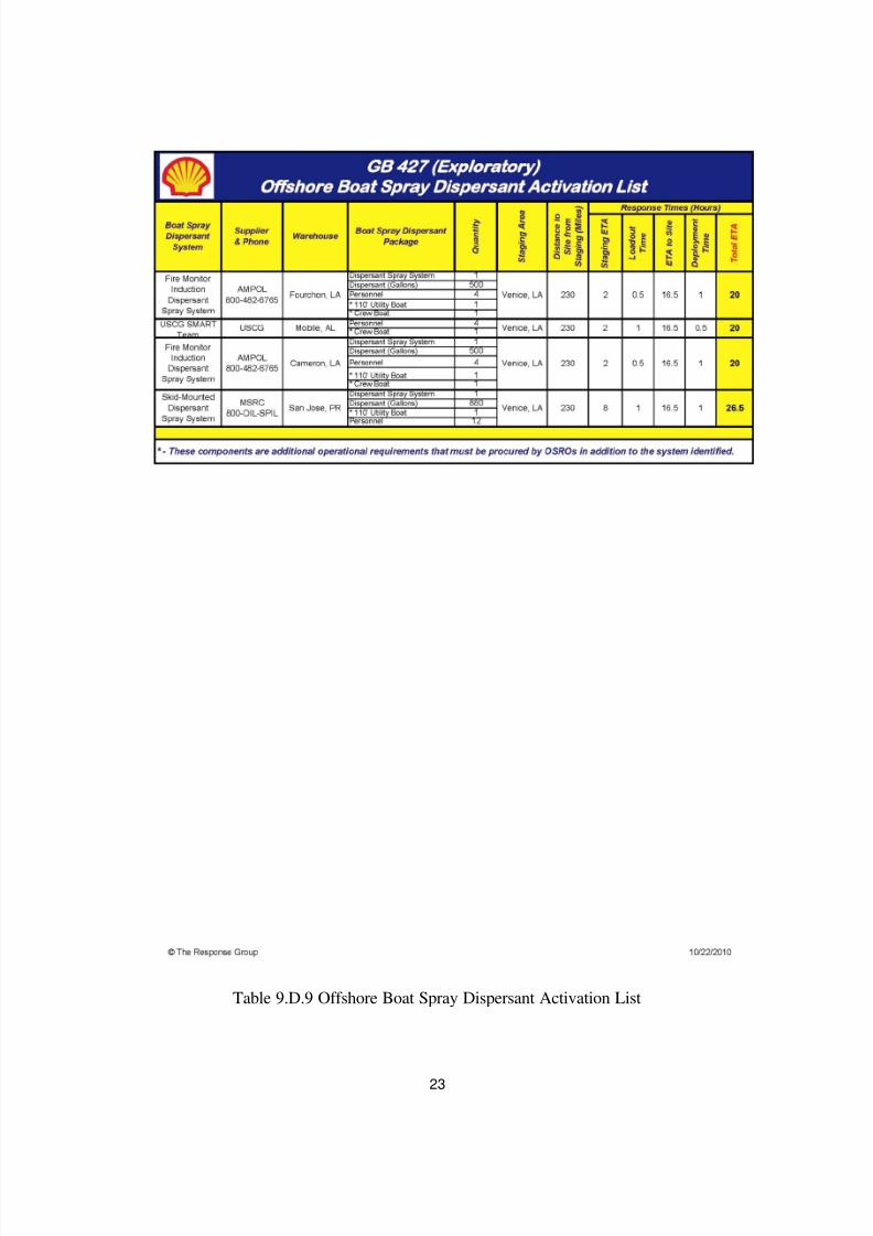
Vessel Dispersant: Vessel dispersant application is another available response option. If appropriate, vessel
spray systems can be installed on offshore vessels of opportunity using inductor nozzles (installed on fire-water
monitors), skid mounted systems, or purpose-built boom arm spray systems. Vessels can apply dispersantwithin the first 12-24 hours of the response and continually as directed.
Table 9.D.9 Offshore Boat Spray Dispersant Activation List
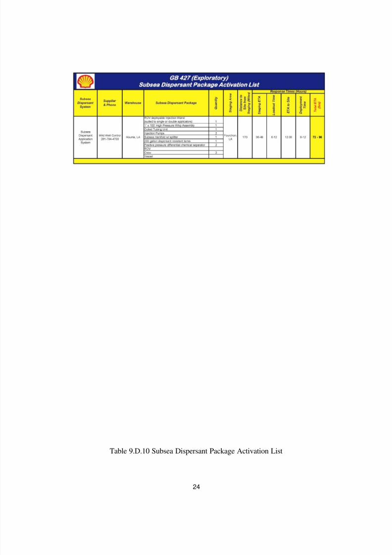
Subsea Dispersant: Shell has contracted with Wild Well Control for a subsea dispersant package. Subsea
dispersant application has been found to be highly effective at reducing the amount of oil reaching the surface.
Additional data collection, laboratory tests and field tests will help in facilitating the optimal application rate
and effectiveness numbers. For planning purposes, The system has the potential to disperse approximately
24,500 to 34,000 barrels of oil per day.
Table 9.D.10 Subsea Dispersant Package Activation List
8/7/2019 Shell exploration plan
http://slidepdf.com/reader/full/shell-exploration-plan 20/48
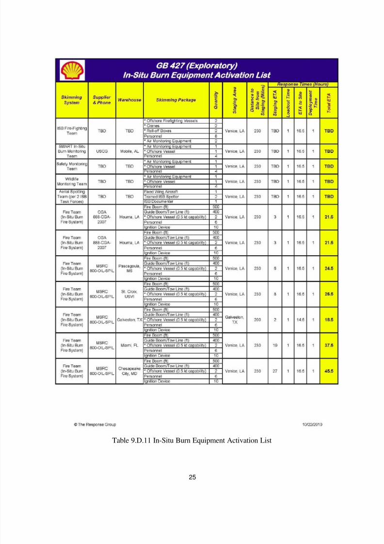
In-Situ Burning: Open-water in-situ burning (ISB) also may be used as a response strategy, depending on the
circumstances of the release. ISB services may be provided by the primary OSRO contractors. If appropriate
conditions exist and approvals are granted, one or multiple ISB task forces could be deployed offshore. Task
forces typically consist of two to four fire teams, each with two vessels capable of towing fire boom, guide
boom or tow line with either a handheld or aerially-deployed oil ignition system. At least one support/safety
boat would be present during active burning operations to provide logistics, safety and monitoring support.
Depending upon a number of factors, up to 4 burns per 12-hour day could be completed per ISB fire team.
Most fire boom systems can be used for approximately 8-12 burns before being replaced. Fire intensity and
weather will be the main determining factors for actual burns per system. Although the actual amount of oil
that will be removed per burn is dependent on many factors, recent data suggests that a typical burn might
eliminate approximately 600 barrels. For planning purposes and based on the above assumptions, a single task
force of four fire teams with the appropriate weather and safety conditions could complete four burns per day
and remove up to ~10,000 bbls/day. In-situ burning nearshore and along shorelines may be a possible option
based on several conditions and with appropriate approvals, as outlined in Section 19, In-situ Burn Plan
(OSRP). In-situ burning along certain types of shorelines may be used to minimize physical damage where
access is limited or if it is determined that mechanical/manual removal may cause a substantial negative impact
on the environment. All safety considerations will be evaluated. In addition, Shell will assess the situation andcan make notification within 48 hours of the initial spill to begin ramping up fire boom production through
contracted OSRO(s). There are potential limitations that need to be assessed prior to ISB operations. Somelimitations include atmospheric and sea conditions; oil weathering; air quality impacts; safety of response
workers; and risk of secondary fires.
Table 9.D.11 In-Situ Burn Equipment Activation List
Shoreline Protection: If the spill went unabated, shoreline impact in St. Bernard or Plaquemines Parish, LA
would depend upon existing environmental conditions. Nearshore response may include the deployment of
shoreline boom on beach areas, or protection and sorbent boom on vegetated areas. Strategies would be based
upon surveillance and real time trajectories provided by The Response Group that depict areas of potential
impact given actual sea and weather conditions. Strategies from the New Orleans, Louisiana Area Contingency
Plan, The Response Group and Unified Command would be consulted to ensure that environmental and special
economic resources would be correctly identified and prioritized to ensure optimal protection. The Response
Group shoreline response guides depict the protection response modes applicable for oil spill clean-up
operations. Each response mode is schematically represented to show optimum deployment and operation of
the equipment in areas of environmental concern. Supervisory personnel have the option to modify the
deployment and operation of equipment allowing a more effective response to site-specific circumstances.
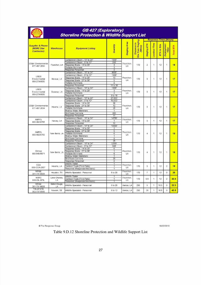
Table 9.D.12 Shoreline Protection and Wildlife Support List
Wildlife Protection: If wildlife is threatened due to a spill, the contracted OSRO’s have resources available to
Shell, which can be utilized to protect and/or rehabilitate wildlife. The resources under contract for the
protection and rehabilitation of affected wildlife are in the following table:
Table 9.D.12 Shoreline Protection and Wildlife Support List
8/7/2019 Shell exploration plan
http://slidepdf.com/reader/full/shell-exploration-plan 21/48
1
Table 9.D.12 Shoreline Protection and Wildlife Support List
Figure 9.C.1 Environmental Sensitivity Index Map Legend
8/7/2019 Shell exploration plan
http://slidepdf.com/reader/full/shell-exploration-plan 22/48
2
Figure 9.C.2 Texas Point ESI Map

8/7/2019 Shell exploration plan
http://slidepdf.com/reader/full/shell-exploration-plan 23/48
3
Figure 9.C.3 Smith Bayou ESI Map
8/7/2019 Shell exploration plan
http://slidepdf.com/reader/full/shell-exploration-plan 24/48
4
.
Figure 9.C.4 Johnsons ESI Map
8/7/2019 Shell exploration plan
http://slidepdf.com/reader/full/shell-exploration-plan 25/48
5
Figure 9.C.5 Peveto Beach ESI Map
8/7/2019 Shell exploration plan
http://slidepdf.com/reader/full/shell-exploration-plan 26/48
6
Figure 9.C.6 Holly Beach ESI Map

8/7/2019 Shell exploration plan
http://slidepdf.com/reader/full/shell-exploration-plan 27/48
7
Figure 9.C.7 Cameron ESI Map
8/7/2019 Shell exploration plan
http://slidepdf.com/reader/full/shell-exploration-plan 28/48
8
Figure 9.C.8 Grand Bayou ESI Map

8/7/2019 Shell exploration plan
http://slidepdf.com/reader/full/shell-exploration-plan 29/48
9
Figure 9.C.9 Creole ESI Map
8/7/2019 Shell exploration plan
http://slidepdf.com/reader/full/shell-exploration-plan 30/48
10
Figure 9.C.10 Hackberry Beach ESI Map

8/7/2019 Shell exploration plan
http://slidepdf.com/reader/full/shell-exploration-plan 31/48
11
Table 9.D.4 Offshore On-Water Recovery Activation List

8/7/2019 Shell exploration plan
http://slidepdf.com/reader/full/shell-exploration-plan 32/48
12
Table 9.D.4 Offshore On-Water Recovery Activation List (continued)
8/7/2019 Shell exploration plan
http://slidepdf.com/reader/full/shell-exploration-plan 33/48
13
Table 9.D.4 Offshore On-Water Recovery Activation List (continued)
8/7/2019 Shell exploration plan
http://slidepdf.com/reader/full/shell-exploration-plan 34/48
14
Table 9.D.4 Offshore On-Water Recovery Activation List (continued)
8/7/2019 Shell exploration plan
http://slidepdf.com/reader/full/shell-exploration-plan 35/48
15
Table 9.D.5 Offshore On-Water Storage Activation List
8/7/2019 Shell exploration plan
http://slidepdf.com/reader/full/shell-exploration-plan 36/48
16
Table 9.D.6 Nearshore On-Water Recovery Activation List
8/7/2019 Shell exploration plan
http://slidepdf.com/reader/full/shell-exploration-plan 37/48
17
Table 9.D.6 Nearshore On-Water Recovery Activation List (continued)
8/7/2019 Shell exploration plan
http://slidepdf.com/reader/full/shell-exploration-plan 38/48
18
Table 9.D.6 Nearshore On-Water Recovery Activation List (continued)
8/7/2019 Shell exploration plan
http://slidepdf.com/reader/full/shell-exploration-plan 39/48
19
Table 9.D.6 Nearshore On-Water Recovery Activation List (continued)

8/7/2019 Shell exploration plan
http://slidepdf.com/reader/full/shell-exploration-plan 40/48
20
Table 9.D.6 Nearshore On-Water Recovery Activation List (continued)
8/7/2019 Shell exploration plan
http://slidepdf.com/reader/full/shell-exploration-plan 41/48
21
Table 9.D.7 Aerial Surveillance Activation List
8/7/2019 Shell exploration plan
http://slidepdf.com/reader/full/shell-exploration-plan 42/48
22
Table 9.D.8 Offshore Aerial Dispersant Activation List
8/7/2019 Shell exploration plan
http://slidepdf.com/reader/full/shell-exploration-plan 43/48
23
Table 9.D.9 Offshore Boat Spray Dispersant Activation List
8/7/2019 Shell exploration plan
http://slidepdf.com/reader/full/shell-exploration-plan 44/48
24
Table 9.D.10 Subsea Dispersant Package Activation List
8/7/2019 Shell exploration plan
http://slidepdf.com/reader/full/shell-exploration-plan 45/48
25
Table 9.D.11 In-Situ Burn Equipment Activation List

8/7/2019 Shell exploration plan
http://slidepdf.com/reader/full/shell-exploration-plan 46/48
26
Table 9.D.11 In-Situ Burn Equipment Activation List (continued)
8/7/2019 Shell exploration plan
http://slidepdf.com/reader/full/shell-exploration-plan 47/48
27
Table 9.D.12 Shoreline Protection and Wildlife Support List

8/7/2019 Shell exploration plan
http://slidepdf.com/reader/full/shell-exploration-plan 48/48
18. Environmental Impact Analysis (EIA)
The updated worst case discharge number of 184,000 BOPD, change in proposed anchor pattern, and
update to the proposed schedule addressed in this amended Exploration Plan do not change theconclusions reached in the EIA submitted as part of the Exploration Plan on October 28, 2010.