REVIEW www.rsc.org/softmatter | Soft Matter
Self-healing materials: a review
Richard P. Wool
Received 31st July 2007, Accepted 30th November 2007
First published as an Advance Article on the web 10th January 2008
DOI: 10.1039/b711716g
The ability of materials to self-heal from mechanical and thermally induced damage is explored in this
paper and has significance in the field of fracture and fatigue. The history and evolution of several
self-repair systems is examined including nano-beam healing elements, passive self-healing, autonomic
self-healing and ballistic self-repair. Self-healing mechanisms utilized in the design of these unusual
materials draw much information from the related field of polymer–polymer interfaces and crack
healing. The relationship of material damage to material healing is examined in a manner to provide an
understanding of the kinetics and damage reversal processes necessary to impart self-healing
characteristics. In self-healing systems, there are transitions from hard-to-soft matter in ballistic impact
and solvent bonding and conversely, soft-to-hard matter transitions in high rate yielding materials and
shear-thickening fluids. These transitions are examined in terms of a new theory of the glass transition
and yielding, viz., the twinkling fractal theory of the hard-to-soft matter transition. Success in the
design of self-healing materials has important consequences for material safety, product performance
and enhanced fatigue lifetime.
1.0 Introduction and overview
Self-healing materials are polymers, metals, ceramics and their
composites that when damaged through thermal, mechanical,
ballistic or other means have the ability to heal and restore the
material to its original set of properties. Few materials intrinsi-
cally possess this ability, and the main topic of this review is
the design for self-repair. This is a very valuable characteristic
to design into a material since it effectively expands the lifetime
use of the product and has desirable economic and human safety
attributes. In this review, the current status of self-healing mate-
rials is examined in Section 1, which explores the history and
Richard P: Wool
Dr Richard Wool is a Professor
of Chemical Engineering and
Director of the Affordable
Composites from Renewable
Resources (ACRES) Program
in the Center for Composite
Materials at the University of
Delaware. He is author of the
books ‘‘Bio-Based Polymers
and Composites’’ and ‘‘Polymer
Interfaces: Structure and
Strength’’. His research inter-
ests are in the fields of bio-based
polymers and composites, crack
healing, fracture, interfaces,
glassy state, polymer entangle-
ments and dynamics.
Department of Chemical Engineering, University of Delaware, Newark DE19716-3144, USA. E-mail: [email protected]
400 | Soft Matter, 2008, 4, 400–418
evolution of several self-repair systems including nanobeam-
healing elements, passive self-healing, autonomic self-healing
and ballistic self-repair. Section 2 examines self-healing mecha-
nisms, which could be deployed in the design of these unusual
materials and draws much information from the related field
of polymer–polymer interfaces and crack healing. The relation-
ship of material damage to material healing is examined in
Section 3 in a manner to provide an understanding of the kinetics
and damage-reversal processes necessary to impart self-healing
characteristics. In self-healing systems, there are transitions
from hard-to-soft matter in ballistic impact and solvent bonding
and conversely, soft-to-hard matter transitions in high rate
yielding materials and shear-thickening fluids used in liquid
armor. These transitions are examined in Section 4 in terms of
a new theory of the glass transition and yielding, viz., the twin-
kling fractal theory of the hard-to-soft matter transition. Section
5 gives an overview of the most recent advances in the self-heal-
ing field, including the biomimetic microfluidic healing skins,
and provides some prospective for the future design of self-heal-
ing materials. The biological analogy of self-healing materials
would be the modification of living tissue and organisms to
promote immortality, and many would agree that partial success
in the form of expanded lifetime would be acceptable. Hopefully,
the reader of this review is left with a sense of what-to-do and
what-not-to-do when designing self-healing materials, perhaps
not always as this author intended.
1.1 Observation of self-healing materials
Materials such as polymers and composites experience damage
and fatigue during their normal utilization and the concept of
eliminating this damage through a self-healing mechanism holds
the promise of enhanced lifetimes and enduring strength.1 This is
especially important in materials that are intended to perform in
a designed manner for significant times where repair is not
This journal is ª The Royal Society of Chemistry 2008
possible. Our early attention to self-healing materials in the 1970s
arose through the need to understand the constitutive properties
of filled elastomers,2–4 such as those used in solid rocket propel-
lants for applications in space exploration (Apollo), Earth studies
(Shuttle) and more recently, ballistic missile interdiction. These
materials consisted of ammonium perchlorate-filled hydroxyl-
terminated polybutadiene cross-linked with diisocyanates. It
was clear that mechanical action caused microscopic damage at
the nanoscale, which could coalesce to form larger microscopic
cracks, which in turn could propagate as macroscopic cracks
and cause catastrophic loss of the material and payload.
However, it became readily apparent that much of this damage
could self-heal and measures of damage through modulus loss
or mechanical stress–strain hysteresis were developed to quantify
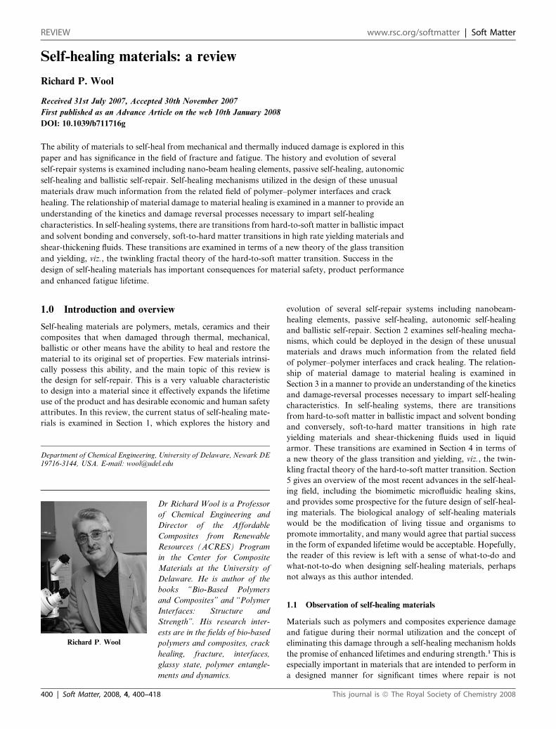
the damage and healing processes.1 The first self-healing mechan-
ical element is shown in Fig. 14.
This reversible self-healing crack element was used to examine
some of basic phenomena of an idealized self-healing element,
which could be used in series or parallel with elementary springs
and dashpots, similar to the Maxwell or Voigt models. It
consisted of two surfaces with an anharmonic potential function
V(l) which would permit yielding at a critical strain ec ¼ lc�1.
What was most interesting about this model was that at high
strain, e.g. l ¼ 10, during stress relaxation, the applied mechan-
ical work was stored reversibly in the new surfaces created, and
would cause the stress to eventually increase before relaxing
completely. This could result in materials with most peculiar
mechanical properties, such as negative creep compliances J(t)
and reactive stress relaxation moduli G(t) where the stress would
first decrease with time and then suddenly increase at constant
strain,4 which bemused unsuspecting visitors to our lab. Such
self-healing material elements can now be made with intercalated
nanoclays and carbon nanotube bundles.5–7 Elastomers based on
functionalized fatty acids were found to critically intercalate and
partially exfoliate nanoclay galleries. The nanoclay galleries were
Fig. 1 (a) The stress–strain response of a healing element is shown where th
function. (b) Viscoelastic elements made with the healing element in series an
This journal is ª The Royal Society of Chemistry 2008
expanded to near-exfoliation by the elastomer and could open or
close with mechanical action thereby producing a mechanical
self-healing process similar to the nanobeams in Fig. 1.
An explicit example of a self-healing material was demon-
strated with hard elastic polypropylene (HPP).8,9 HPP is a
stress-crystallized PP which has a morphology consisting of
stacked lamella perpendicular to the extrusion direction of the
fibers or films. When stretched along the fiber axis, the lamellae
would splay apart permitting large reversible strains up to 500%,
as shown in Fig. 2 and 3.
The initial high modulus of this polymer and its subsequent
elastomeric behavior earned it the name of hard-elastic polymers,
which are quite unique to row-nucleated semicrystalline poly-
mers. The resulting network fracture morphology was often
compared to a ‘‘Christmas paper bell’’. The mechanical proper-
ties shown in Fig. 3 show that the HPP when allowed to rest
at room temperature could completely recover its high elasticity
as the interlamellar microvoids healed. In detailed studies, we
found that the interlamellar fracture damage could be
completely healed at room temperature and accelerated with
higher temperature.1,9
We subsequently discovered that crack healing was fairly
ubiquitous in polymer materials and systematically studied
microvoid healing, craze healing and crack healing in a variety of
materials, such as crazes in polystyrene,10,11 microvoids in SBS
block copolymer elastomers12 and others which are reviewed in
ref. 1. In a seminal study, Kausch and co-workers13–15 showed
that single cracks that were formed at room temperature in frac-
ture mechanics specimens of PMMA could be completely
rehealed when the surfaces were rejoined and welded above the
glass transition temperature Tg. Much work has been done by
our group16–25 and others26–68 to understand the concept of
strength development at polymer–polymer interfaces and poly-
mer–solid interfaces69–75 in terms of the fundamental dynamics
of entangled polymers. Using DeGennes’ reptation dynamics
e two parallel surfaces interact by an anharmonic non-bonded potential
d parallel with a viscous dashpot [Wool 1978].
Soft Matter, 2008, 4, 400–418 | 401
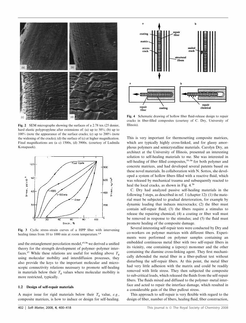
Fig. 4 Schematic drawing of hollow fiber fluid-release design to repair
cracks in fiber-filled composites (courtesy of C. Dry, University of
Illinois).
Fig. 3 Cyclic stress–strain curves of a HPP fiber with intervening
healing times from 10 to 1000 min at room temperature.1,9
Fig. 2 SEM micrographs showing the surfaces of a 2.78 tex (25 denier,
hard elastic polypropylene after extensions of: (a) up to 50%; (b) up to
100% (note the appearance of the surface cracks; (c) up to 200% (note
the widening of the cracks); (d) the surface of (c) at higher magnification.
Final magnifications are (a–c) 1500x, (d) 3900x. (courtesy of Ludmila
Konapasek).
and the entanglement percolation model,17,76 we derived a unified
theory for the strength development of polymer–polymer inter-
faces.17 While these relations are useful for welding above Tg
using molecular mobility and interdiffusion processes, they
also provide the keys to the important molecular and micro-
scopic connectivity relations necessary to promote self-healing
in materials below their Tg values where molecular mobility is
more restricted, typically.
1.2 Design of self-repair materials
A major issue for rigid materials below their Tg value, e.g.,
composite matrices, is how to induce or design for self-healing.
402 | Soft Matter, 2008, 4, 400–418
This is very important for thermosetting composite matrices,
which are typically highly cross-linked, and for glassy amor-
phous polymers and semicrystalline materials. Carolyn Dry, an
architect at the University of Illinois, presented an interesting
solution to self-healing materials to me. She was interested in
self-healing of fiber filled composites,77–79 for both polymer and
concrete matrices, and had developed several patents based on
these novel materials. In collaboration with N. Sottos, she devel-
oped a system of hollow fibers filled with a reactive fluid, which
was released by mechanical trauma and subsequently reacted to
heal the local cracks, as shown in Fig. 4.79
C. Dry had analyzed passive self-healing materials in the
following 5 steps, as described in ref. 1 (chapter 12): (1) the mate-
rial must be subjected to gradual deterioration, for example by
dynamic loading that induces microcracks; (2) the fiber must
contain self-repair fluid; (3) the fibers require a stimulus to
release the repairing chemical; (4) a coating or fiber wall must
be removed in response to the stimulus; and (5) the fluid must
promote healing of the composite damage.
Several interesting self-repair tests were conducted by Dry and
co-workers on polymer matrices with different fibers. Experi-
ments were performed on polymer samples containing an
embedded continuous metal fiber with two self-repair fibers in
its vicinity, one containing a (epoxy) monomer and the other
containing the diamine cross-linking agent. They first mechani-
cally debonded the metal fiber in a fiber-pullout test without
disturbing the self-repair fibers. At this point, the metal fiber
had very little adhesion with the matrix and could be readily
removed with little stress. They then subjected the composite
to sub-critical loads, which released the fluids from the self-repair
fibers. The fluids mixed and diffused to the polymer–metal inter-
face and acted to repair the interface damage, which resulted in
a considerable gain of the fiber pullout stress.
This approach to self-repair is very flexible with regard to the
design of fiber, number of fibers, healing fluid, fiber construction,
This journal is ª The Royal Society of Chemistry 2008
fiber coating and so forth. The healing fluid could be a cross-
linking epoxy or polyester, a chemical agent that reacts with
the matrix, or one that reacts selectively with the damaged
surface. For example, one could use vinyl monomers in places
where microcracks in the matrix generate free radicals. The
free radicals would then polymerize the fluid and help promote
strength. Matrix solvents could also be used to promote solvent
bonding in microvoids. Thermally induced healing can also be
induced by exothermic reactions of the self-repair fluid, either
with itself or with components of the composite. We will return
to this passive self-healing mechanism later.
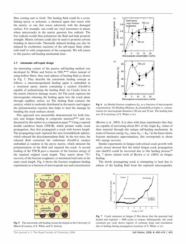
Fig. 6 (a) Healed fracture toughness KIC as a function of microcapsule
concentration. (b) Healing efficiency KIC(healed)/KIC(virgin) vs. concen-
tration for microcapsule diameters 180 mm and 50 mm. The healing time
was 24 h (courtesy of S. White et al.).
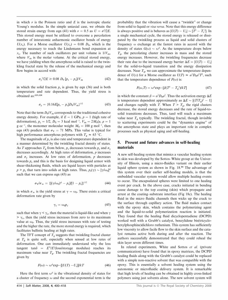
1.3 Autonomic self-repair design
An interesting variant of the passive self-healing method was
developed by White and Sottos in 2001,80–83 where instead of
using hollow fibers, they used spheres of healing fluid as shown
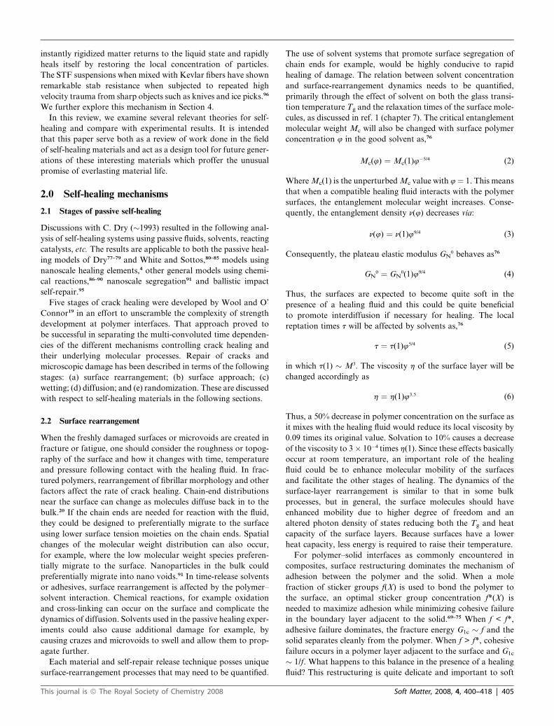
in Fig. 5. They describe the autonomic healing concept as
follows: a microencapsulated healing agent is embedded in
a structural epoxy matrix containing a catalyst (Grubb’s)
capable of polymerizing the healing fluid. (a) Cracks form in
the matrix wherever damage occurs. (b) The crack ruptures the
microcapsules releasing the healing agent into the crack plane
through capillary action. (c) The healing fluid contacts the
catalyst, which is randomly distributed in the matrix and triggers
the polymerization reaction that helps to heal the damage by
bonding the crack surfaces closed.
This approach was successfully demonstrated for both frac-
ture and fatigue healing in composite matrices80–84 and was
discussed by this author in a companion paper.85 Using a tapered
double cantilever beam (TDCB), which permits stable crack
propagation, they first propagated a crack with known length.
The propagating crack ruptured the urea formaldehyde spheres,
which released the dicyclopentadiene fluid. In the rest state, the
released fluid contacted the ruthenium (Grubb’s) catalyst
embedded at random in the epoxy matrix, which initiated the
polymerization of the fluid and repaired the crack. A second
loading of the TDCB gave a measure of the fracture energy of
the repaired original crack length. They report about 75%
recovery of the fracture toughness, or maximum load ratio at the
same crack length. Fig. 6 shows the fracture toughness healing
experiments as a function of microcapsule size and concentration
Fig. 5 The autonomic self-healing system developed at the University of
Illinois [Courtesy of S. White and N. Sottos].
This journal is ª The Royal Society of Chemistry 2008
(Brown et al., 2003). It is clear with these experiments that they
are capable of recovering about 80% of the virgin KIC values of
their material through this unique self-healing mechanism. In
terms of fracture energy GIC, since GIC � KIC2 in the linear elastic
fracture mechanics approximation, this corresponds to about
64% energy recovery.
Similar experiments in fatigue (sub-critical crack growth with
cyclic stress) showed that the initial fatigue crack propagation
rate (da/dN) could be recovered due to this healing process.82
Fig. 7 shows related work of Brown et al. (2005) on fatigue
healing.
The slowly propagating crack is attempting to heal due to
release of the healing fluid from the ruptured microcapsules.
Fig. 7 Crack extension in fatigue (5 Hz) shows that the precrack had
healed and required � 3000 cycles to reopen. Subsequently, the crack
extension per cycle shows regions of constant slope and retardation
due to healing during propagation (courtesy of S. White et al.).
Soft Matter, 2008, 4, 400–418 | 403
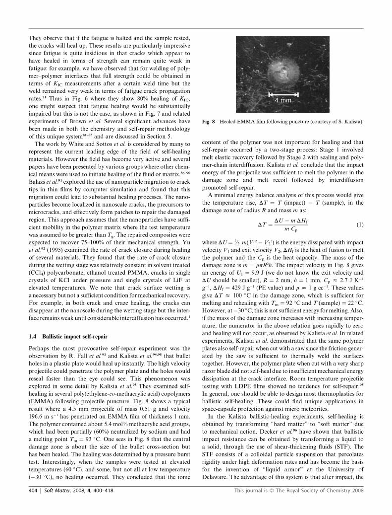
Fig. 8 Healed EMMA film following puncture (courtesy of S. Kalista).
They observe that if the fatigue is halted and the sample rested,
the cracks will heal up. These results are particularly impressive
since fatigue is quite insidious in that cracks which appear to
have healed in terms of strength can remain quite weak in
fatigue: for example, we have observed that for welding of poly-
mer–polymer interfaces that full strength could be obtained in
terms of KIC measurements after a certain weld time but the
weld remained very weak in terms of fatigue crack propagation
rates.21 Thus in Fig. 6 where they show 80% healing of KIC,
one might suspect that fatigue healing would be substantially
impaired but this is not the case, as shown in Fig. 7 and related
experiments of Brown et al. Several significant advances have
been made in both the chemistry and self-repair methodology
of this unique system81–85 and are discussed in Section 5.
The work by White and Sottos et al. is considered by many to
represent the current leading edge of the field of self-healing
materials. However the field has become very active and several
papers have been presented by various groups where other chem-
ical means were used to initiate healing of the fluid or matrix.86–90
Balazs et al.91 explored the use of nanoparticle migration to crack
tips in thin films by computer simulation and found that this
migration could lead to substantial healing processes. The nano-
particles become localized in nanoscale cracks, the precursors to
microcracks, and effectively form patches to repair the damaged
region. This approach assumes that the nanoparticles have suffi-
cient mobility in the polymer matrix where the test temperature
was assumed to be greater than Tg. The repaired composites were
expected to recover 75–100% of their mechanical strength. Yu
et al.92 (1995) examined the rate of crack closure during healing
of several materials. They found that the rate of crack closure
during the wetting stage was relatively constant in solvent treated
(CCl4) polycarbonate, ethanol treated PMMA, cracks in single
crystals of KCl under pressure and single crystals of LiF at
elevated temperatures. We note that crack surface wetting is
a necessary but not a sufficient condition formechanical recovery.
For example, in both crack and craze healing, the cracks can
disappear at the nanoscale during the wetting stage but the inter-
face remainsweak until considerable interdiffusion has occurred.1
1.4 Ballistic impact self-repair
Perhaps the most provocative self-repair experiment was the
observation by R. Fall et al.93 and Kalista et al.94,95 that bullet
holes in a plastic plate would heal up instantly. The high velocity
projectile could penetrate the polymer plate and the holes would
reseal faster than the eye could see. This phenomenon was
explored in some detail by Kalista et al.95 They examined self-
healing in several poly(ethylene-co-methacrylic acid) copolymers
(EMMA) following projectile puncture. Fig. 8 shows a typical
result where a 4.5 mm projectile of mass 0.51 g and velocity
196.6 m s�1 has penetrated an EMMA film of thickness 1 mm.
The polymer contained about 5.4 mol% methacrylic acid groups,
which had been partially (60%) neutralized by sodium and had
a melting point Tm ¼ 93 �C. One sees in Fig. 8 that the central
damage zone is about the size of the bullet cross-section but
has been healed. The healing was determined by a pressure burst
test. Interestingly, when the samples were tested at elevated
temperatures (60 �C), and some, but not all at low temperature
(�30 �C), no healing occurred. They concluded that the ionic
404 | Soft Matter, 2008, 4, 400–418
content of the polymer was not important for healing and that
self-repair occurred by a two-stage process: Stage 1 involved
melt elastic recovery followed by Stage 2 with sealing and poly-
mer-chain interdiffusion. Kalista et al. conclude that the impact
energy of the projectile was sufficient to melt the polymer in the
damage zone and melt recoil followed by interdiffusion
promoted self-repair.
A minimal energy balance analysis of this process would give
the temperature rise, DT ¼ T (impact) � T (sample), in the
damage zone of radius R and mass m as:
DT ¼ DU � m DHf
m Cp
(1)
where DU ¼ 1⁄2 m(V12 � V2
2) is the energy dissipated with impact
velocity V1 and exit velocity V2, DHf is the heat of fusion to melt
the polymer and the Cp is the heat capacity. The mass of the
damage zone is m ¼ rpR2h. The impact velocity in Fig. 8 gives
an energy of U1 ¼ 9.9 J (we do not know the exit velocity and
DU should be smaller), R ¼ 2 mm, h ¼ 1 mm, Cp z 2.7 J K�1
g�1, DHf ¼ 429 J g�1 (PE value) and r z 1 g cc�1. These values
give DT z 100 �C in the damage zone, which is sufficient for
melting and rehealing with Tm ¼ 92 �C and T (sample) ¼ 22 �C.
However, at�30 �C, this is not sufficient energy formelting. Also,
if the mass of the damage zone increases with increasing temper-
ature, the numerator in the above relation goes rapidly to zero
and healing will not occur, as observed by Kalista et al. In related
experiments, Kalista et al. demonstrated that the same polymer
plates also self-repair when cut with a saw since the friction gener-
ated by the saw is sufficient to thermally weld the surfaces
together. However, the polymer plate when cut with a very sharp
razor blade did not self-heal due to insufficient mechanical energy
dissipation at the crack interface. Room temperature projectile
testing with LDPE films showed no tendency for self-repair.95
In general, one should be able to design most thermoplastics for
ballistic self-healing. These could find unique applications in
space-capsule protection against micro meteorites.
In the Kalista ballistic-healing experiments, self-healing is
obtained by transforming ‘‘hard matter’’ to ‘‘soft matter’’ due
to mechanical action. Decker et al.96 have shown that ballistic
impact resistance can be obtained by transforming a liquid to
a solid, through the use of shear-thickening fluids (STF). The
STF consists of a colloidal particle suspension that percolates
rigidity under high deformation rates and has become the basis
for the invention of ‘‘liquid armor’’ at the University of
Delaware. The advantage of this system is that after impact, the
This journal is ª The Royal Society of Chemistry 2008
instantly rigidized matter returns to the liquid state and rapidly
heals itself by restoring the local concentration of particles.
The STF suspensions when mixed with Kevlar fibers have shown
remarkable stab resistance when subjected to repeated high
velocity trauma from sharp objects such as knives and ice picks.96
We further explore this mechanism in Section 4.
In this review, we examine several relevant theories for self-
healing and compare with experimental results. It is intended
that this paper serve both as a review of work done in the field
of self-healing materials and act as a design tool for future gener-
ations of these interesting materials which proffer the unusual
promise of everlasting material life.
2.0 Self-healing mechanisms
2.1 Stages of passive self-healing
Discussions with C. Dry (�1993) resulted in the following anal-
ysis of self-healing systems using passive fluids, solvents, reacting
catalysts, etc. The results are applicable to both the passive heal-
ing models of Dry77–79 and White and Sottos,80–85 models using
nanoscale healing elements,4 other general models using chemi-
cal reactions,86–90 nanoscale segregation91 and ballistic impact
self-repair.95
Five stages of crack healing were developed by Wool and O’
Connor19 in an effort to unscramble the complexity of strength
development at polymer interfaces. That approach proved to
be successful in separating the multi-convoluted time dependen-
cies of the different mechanisms controlling crack healing and
their underlying molecular processes. Repair of cracks and
microscopic damage has been described in terms of the following
stages: (a) surface rearrangement; (b) surface approach; (c)
wetting; (d) diffusion; and (e) randomization. These are discussed
with respect to self-healing materials in the following sections.
2.2 Surface rearrangement
When the freshly damaged surfaces or microvoids are created in
fracture or fatigue, one should consider the roughness or topog-
raphy of the surface and how it changes with time, temperature
and pressure following contact with the healing fluid. In frac-
tured polymers, rearrangement of fibrillar morphology and other
factors affect the rate of crack healing. Chain-end distributions
near the surface can change as molecules diffuse back in to the
bulk.20 If the chain ends are needed for reaction with the fluid,
they could be designed to preferentially migrate to the surface
using lower surface tension moieties on the chain ends. Spatial
changes of the molecular weight distribution can also occur,
for example, where the low molecular weight species preferen-
tially migrate to the surface. Nanoparticles in the bulk could
preferentially migrate into nano voids.91 In time-release solvents
or adhesives, surface rearrangement is affected by the polymer–
solvent interaction. Chemical reactions, for example oxidation
and cross-linking can occur on the surface and complicate the
dynamics of diffusion. Solvents used in the passive healing exper-
iments could also cause additional damage for example, by
causing crazes and microvoids to swell and allow them to prop-
agate further.
Each material and self-repair release technique posses unique
surface-rearrangement processes that may need to be quantified.
This journal is ª The Royal Society of Chemistry 2008
The use of solvent systems that promote surface segregation of
chain ends for example, would be highly conducive to rapid
healing of damage. The relation between solvent concentration
and surface-rearrangement dynamics needs to be quantified,
primarily through the effect of solvent on both the glass transi-
tion temperature Tg and the relaxation times of the surface mole-
cules, as discussed in ref. 1 (chapter 7). The critical entanglement
molecular weight Mc will also be changed with surface polymer
concentration 4 in the good solvent as,76
Mc(4) ¼ Mc(1)4�5/4 (2)
Where Mc(1) is the unperturbed Mc value with 4¼ 1. This means
that when a compatible healing fluid interacts with the polymer
surfaces, the entanglement molecular weight increases. Conse-
quently, the entanglement density n(4) decreases via:
n(4) ¼ n(1)49/4 (3)
Consequently, the plateau elastic modulus GN0 behaves as76
GN0 ¼ GN
0(1)49/4 (4)
Thus, the surfaces are expected to become quite soft in the
presence of a healing fluid and this could be quite beneficial
to promote interdiffusion if necessary for healing. The local
reptation times t will be affected by solvents as,76
t ¼ t(1)45/4 (5)
in which t(1) � M3. The viscosity h of the surface layer will be
changed accordingly as
h ¼ h(1)43.5 (6)
Thus, a 50% decrease in polymer concentration on the surface as
it mixes with the healing fluid would reduce its local viscosity by
0.09 times its original value. Solvation to 10% causes a decrease
of the viscosity to 3� 10�4 times h(1). Since these effects basically
occur at room temperature, an important role of the healing
fluid could be to enhance molecular mobility of the surfaces
and facilitate the other stages of healing. The dynamics of the
surface-layer rearrangement is similar to that in some bulk
processes, but in general, the surface molecules should have
enhanced mobility due to higher degree of freedom and an
altered photon density of states reducing both the Tg and heat
capacity of the surface layers. Because surfaces have a lower
heat capacity, less energy is required to raise their temperature.
For polymer–solid interfaces as commonly encountered in
composites, surface restructuring dominates the mechanism of
adhesion between the polymer and the solid. When a mole
fraction of sticker groups f(X) is used to bond the polymer to
the surface, an optimal sticker group concentration f*(X) is
needed to maximize adhesion while minimizing cohesive failure
in the boundary layer adjacent to the solid.69–75 When f < f*,
adhesive failure dominates, the fracture energy G1c � f and the
solid separates cleanly from the polymer. When f > f*, cohesive
failure occurs in a polymer layer adjacent to the surface and G1c
� 1/f. What happens to this balance in the presence of a healing
fluid? This restructuring is quite delicate and important to soft
Soft Matter, 2008, 4, 400–418 | 405
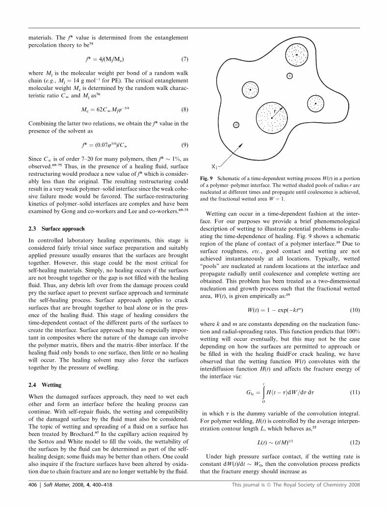
Fig. 9 Schematic of a time-dependent wetting process W(t) in a portion
of a polymer–polymer interface. The wetted shaded pools of radius r are
nucleated at different times and propagate until coalescence is achieved,
and the fractional wetted area W ¼ 1.
materials. The f* value is determined from the entanglement
percolation theory to be75
f* ¼ 4j(Mj/Mc) (7)
where Mj is the molecular weight per bond of a random walk
chain (e.g., Mj ¼ 14 g mol�1 for PE). The critical entanglement
molecular weight Mc is determined by the random walk charac-
teristic ratio CN and Mj as76
Mc ¼ 62CNMj4�5/4 (8)
Combining the latter two relations, we obtain the f* value in the
presence of the solvent as
f* ¼ (0.0745/4)/Cf (9)
Since Cf is of order 7–20 for many polymers, then f* � 1%, as
observed.69–75 Thus, in the presence of a healing fluid, surface
restructuring would produce a new value of f* which is consider-
ably less than the original. The resulting restructuring could
result in a very weak polymer–solid interface since the weak cohe-
sive failure mode would be favored. The surface-restructuring
kinetics of polymer–solid interfaces are complex and have been
examined by Gong and co-workers and Lee and co-workers.69–75
2.3 Surface approach
In controlled laboratory healing experiments, this stage is
considered fairly trivial since surface preparation and suitably
applied pressure usually ensures that the surfaces are brought
together. However, this stage could be the most critical for
self-healing materials. Simply, no healing occurs if the surfaces
are not brought together or the gap is not filled with the healing
fluid. Thus, any debris left over from the damage process could
pry the surface apart to prevent surface approach and terminate
the self-healing process. Surface approach applies to crack
surfaces that are brought together to heal alone or in the pres-
ence of the healing fluid. This stage of healing considers the
time-dependent contact of the different parts of the surfaces to
create the interface. Surface approach may be especially impor-
tant in composites where the nature of the damage can involve
the polymer matrix, fibers and the matrix–fiber interface. If the
healing fluid only bonds to one surface, then little or no healing
will occur. The healing solvent may also force the surfaces
together by the pressure of swelling.
2.4 Wetting
When the damaged surfaces approach, they need to wet each
other and form an interface before the healing process can
continue. With self-repair fluids, the wetting and compatibility
of the damaged surface by the fluid must also be considered.
The topic of wetting and spreading of a fluid on a surface has
been treated by Brochard.97 In the capillary action required by
the Sottos and White model to fill the voids, the wettability of
the surfaces by the fluid can be determined as part of the self-
healing design; some fluids may be better than others. One could
also inquire if the fracture surfaces have been altered by oxida-
tion due to chain fracture and are no longer wettable by the fluid.
406 | Soft Matter, 2008, 4, 400–418
Wetting can occur in a time-dependent fashion at the inter-
face. For our purposes we provide a brief phenomenological
description of wetting to illustrate potential problems in evalu-
ating the time-dependence of healing. Fig. 9 shows a schematic
region of the plane of contact of a polymer interface.19 Due to
surface roughness, etc., good contact and wetting are not
achieved instantaneously at all locations. Typically, wetted
‘‘pools’’ are nucleated at random locations at the interface and
propagate radially until coalescence and complete wetting are
obtained. This problem has been treated as a two-dimensional
nucleation and growth process such that the fractional wetted
area, W(t), is given empirically as:19
W(t) ¼ 1 � exp(�ktm) (10)
where k and m are constants depending on the nucleation func-
tion and radial-spreading rates. This function predicts that 100%
wetting will occur eventually, but this may not be the case
depending on how the surfaces are permitted to approach or
be filled in with the healing fluidFor crack healing, we have
observed that the wetting function W(t) convolutes with the
interdiffusion function H(t) and affects the fracture energy of
the interface via:
G1c ¼ðt
O
Hðt � tÞdW=dt dt (11)
in which t is the dummy variable of the convolution integral.
For polymer welding, H(t) is controlled by the average interpen-
etration contour length L, which behaves as,22
L(t) � (t/M)1/2 (12)
Under high pressure surface contact, if the wetting rate is
constant dW(t)/dt � W0, then the convolution process predicts
that the fracture energy should increase as
This journal is ª The Royal Society of Chemistry 2008
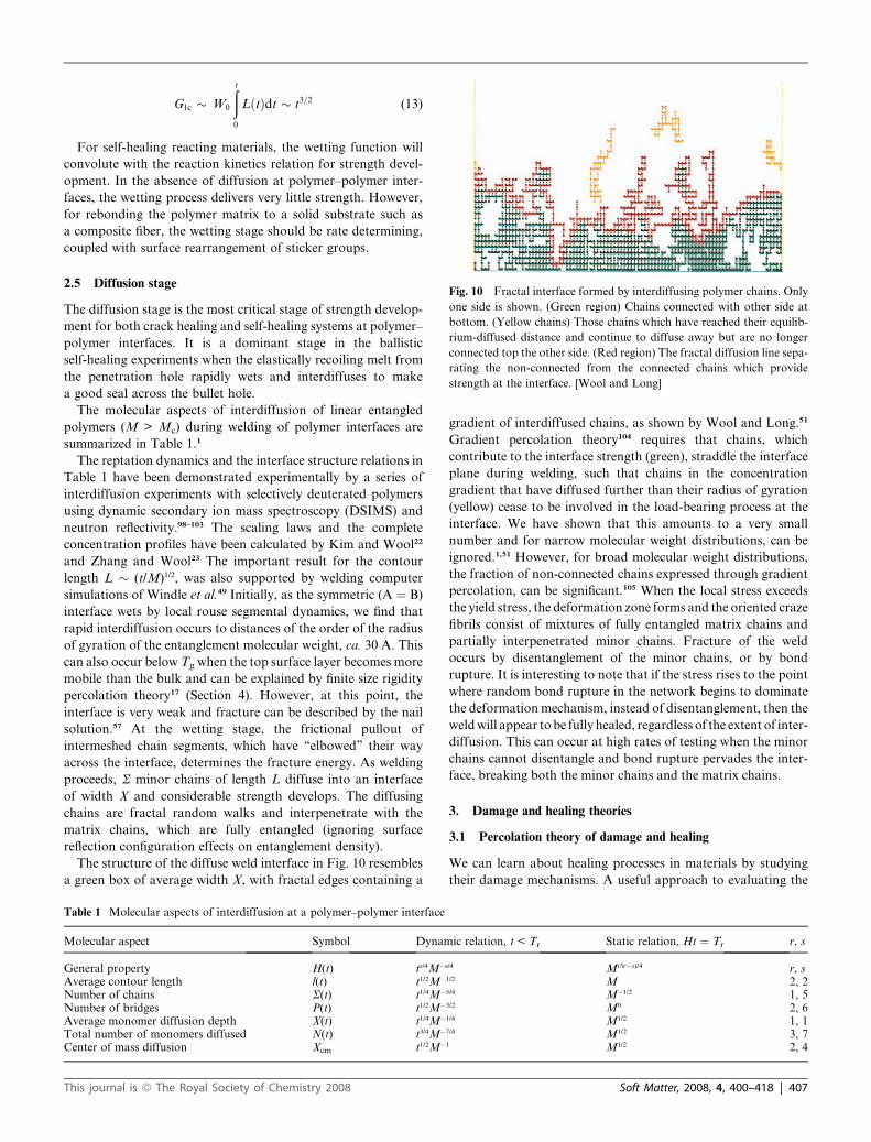
Fig. 10 Fractal interface formed by interdiffusing polymer chains. Only
one side is shown. (Green region) Chains connected with other side at
bottom. (Yellow chains) Those chains which have reached their equilib-
rium-diffused distance and continue to diffuse away but are no longer
connected top the other side. (Red region) The fractal diffusion line sepa-
rating the non-connected from the connected chains which provide
strength at the interface. [Wool and Long]
G1c � W0
ðt
0
LðtÞdt � t3=2 (13)
For self-healing reacting materials, the wetting function will
convolute with the reaction kinetics relation for strength devel-
opment. In the absence of diffusion at polymer–polymer inter-
faces, the wetting process delivers very little strength. However,
for rebonding the polymer matrix to a solid substrate such as
a composite fiber, the wetting stage should be rate determining,
coupled with surface rearrangement of sticker groups.
2.5 Diffusion stage
The diffusion stage is the most critical stage of strength develop-
ment for both crack healing and self-healing systems at polymer–
polymer interfaces. It is a dominant stage in the ballistic
self-healing experiments when the elastically recoiling melt from
the penetration hole rapidly wets and interdiffuses to make
a good seal across the bullet hole.
The molecular aspects of interdiffusion of linear entangled
polymers (M > Mc) during welding of polymer interfaces are
summarized in Table 1.1
The reptation dynamics and the interface structure relations in
Table 1 have been demonstrated experimentally by a series of
interdiffusion experiments with selectively deuterated polymers
using dynamic secondary ion mass spectroscopy (DSIMS) and
neutron reflectivity.98–103 The scaling laws and the complete
concentration profiles have been calculated by Kim and Wool22
and Zhang and Wool23 The important result for the contour
length L � (t/M)1/2, was also supported by welding computer
simulations of Windle et al.49 Initially, as the symmetric (A ¼ B)
interface wets by local rouse segmental dynamics, we find that
rapid interdiffusion occurs to distances of the order of the radius
of gyration of the entanglement molecular weight, ca. 30 A. This
can also occur below Tg when the top surface layer becomes more
mobile than the bulk and can be explained by finite size rigidity
percolation theory17 (Section 4). However, at this point, the
interface is very weak and fracture can be described by the nail
solution.57 At the wetting stage, the frictional pullout of
intermeshed chain segments, which have ‘‘elbowed’’ their way
across the interface, determines the fracture energy. As welding
proceeds, S minor chains of length L diffuse into an interface
of width X and considerable strength develops. The diffusing
chains are fractal random walks and interpenetrate with the
matrix chains, which are fully entangled (ignoring surface
reflection configuration effects on entanglement density).
The structure of the diffuse weld interface in Fig. 10 resembles
a green box of average width X, with fractal edges containing a
Table 1 Molecular aspects of interdiffusion at a polymer–polymer interface
Molecular aspect Symbol Dynam
General property H(t) tr/4M�s
Average contour length l(t) t1/2M�
Number of chains S(t) t1/4M�
Number of bridges P(t) t1/2M�
Average monomer diffusion depth X(t) t1/4M�
Total number of monomers diffused N(t) t3/4M�
Center of mass diffusion Xcm t1/2M�
This journal is ª The Royal Society of Chemistry 2008
gradient of interdiffused chains, as shown by Wool and Long.51
Gradient percolation theory104 requires that chains, which
contribute to the interface strength (green), straddle the interface
plane during welding, such that chains in the concentration
gradient that have diffused further than their radius of gyration
(yellow) cease to be involved in the load-bearing process at the
interface. We have shown that this amounts to a very small
number and for narrow molecular weight distributions, can be
ignored.1,51 However, for broad molecular weight distributions,
the fraction of non-connected chains expressed through gradient
percolation, can be significant.105 When the local stress exceeds
the yield stress, the deformation zone forms and the oriented craze
fibrils consist of mixtures of fully entangled matrix chains and
partially interpenetrated minor chains. Fracture of the weld
occurs by disentanglement of the minor chains, or by bond
rupture. It is interesting to note that if the stress rises to the point
where random bond rupture in the network begins to dominate
the deformationmechanism, instead of disentanglement, then the
weldwill appear tobe fully healed, regardless of the extent of inter-
diffusion. This can occur at high rates of testing when the minor
chains cannot disentangle and bond rupture pervades the inter-
face, breaking both the minor chains and the matrix chains.
3. Damage and healing theories
3.1 Percolation theory of damage and healing
We can learn about healing processes in materials by studying
their damage mechanisms. A useful approach to evaluating the
ic relation, t < Tr Static relation, Ht ¼ Tr r, s
/4 M(3r�s)/4 r, s1/2 M 2, 25/4 M�1/2 1, 53/2 M0 2, 61/4 M1/2 1, 17/4 M1/2 3, 71 M1/2 2, 4
Soft Matter, 2008, 4, 400–418 | 407
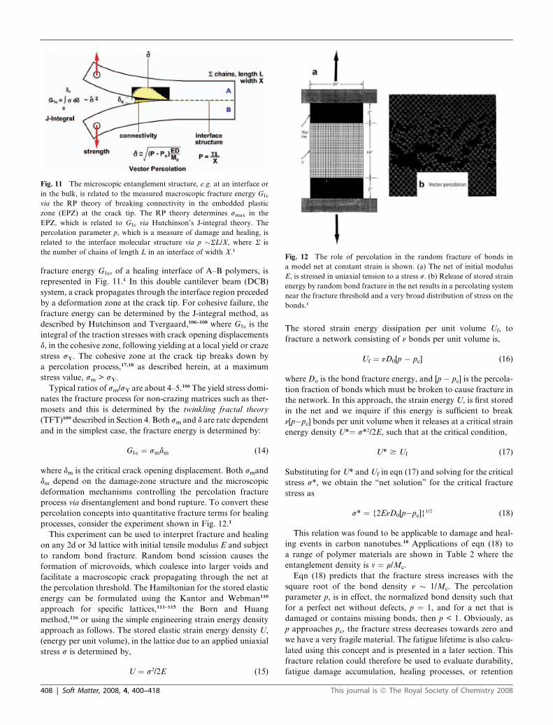
Fig. 11 The microscopic entanglement structure, e.g. at an interface or
in the bulk, is related to the measured macroscopic fracture energy G1c
via the RP theory of breaking connectivity in the embedded plastic
zone (EPZ) at the crack tip. The RP theory determines smax in the
EPZ, which is related to G1c via Hutchinson’s J-integral theory. The
percolation parameter p, which is a measure of damage and healing, is
related to the interface molecular structure via p �SL/X, where S is
the number of chains of length L in an interface of width X.1Fig. 12 The role of percolation in the random fracture of bonds in
a model net at constant strain is shown. (a) The net of initial modulus
E, is stressed in uniaxial tension to a stress s. (b) Release of stored strain
energy by random bond fracture in the net results in a percolating system
near the fracture threshold and a very broad distribution of stress on the
bonds.1
fracture energy G1c, of a healing interface of A–B polymers, is
represented in Fig. 11.1 In this double cantilever beam (DCB)
system, a crack propagates through the interface region preceded
by a deformation zone at the crack tip. For cohesive failure, the
fracture energy can be determined by the J-integral method, as
described by Hutchinson and Tvergaard,106–108 where G1c is the
integral of the traction stresses with crack opening displacements
d, in the cohesive zone, following yielding at a local yield or craze
stress sY. The cohesive zone at the crack tip breaks down by
a percolation process,17,18 as described herein, at a maximum
stress value, sm > sY.
Typical ratios of sm/sY are about 4–5.106 The yield stress domi-
nates the fracture process for non-crazing matrices such as ther-
mosets and this is determined by the twinkling fractal theory
(TFT)109 described in Section 4. Both sm and d are rate dependent
and in the simplest case, the fracture energy is determined by:
G1c ¼ smdm (14)
where dm is the critical crack opening displacement. Both smand
dm depend on the damage-zone structure and the microscopic
deformation mechanisms controlling the percolation fracture
process via disentanglement and bond rupture. To convert these
percolation concepts into quantitative fracture terms for healing
processes, consider the experiment shown in Fig. 12.1
This experiment can be used to interpret fracture and healing
on any 2d or 3d lattice with initial tensile modulus E and subject
to random bond fracture. Random bond scission causes the
formation of microvoids, which coalesce into larger voids and
facilitate a macroscopic crack propagating through the net at
the percolation threshold. The Hamiltonian for the stored elastic
energy can be formulated using the Kantor and Webman110
approach for specific lattices,111–115 the Born and Huang
method,116 or using the simple engineering strain energy density
approach as follows. The stored elastic strain energy density U,
(energy per unit volume), in the lattice due to an applied uniaxial
stress s is determined by,
U ¼ s2/2E (15)
408 | Soft Matter, 2008, 4, 400–418
The stored strain energy dissipation per unit volume Uf, to
fracture a network consisting of n bonds per unit volume is,
Uf ¼ nD0[p � pc] (16)
where Do is the bond fracture energy, and [p � pc] is the percola-
tion fraction of bonds which must be broken to cause fracture in
the network. In this approach, the strain energy U, is first stored
in the net and we inquire if this energy is sufficient to break
n[p�pc] bonds per unit volume when it releases at a critical strain
energy density U*¼ s*2/2E, such that at the critical condition,
U* $ Uf (17)
Substituting for U* and Uf in eqn (17) and solving for the critical
stress s*, we obtain the ‘‘net solution’’ for the critical fracture
stress as
s* ¼ {2EnD0[p�pc]}1/2 (18)
This relation was found to be applicable to damage and heal-
ing events in carbon nanotubes.18 Applications of eqn (18) to
a range of polymer materials are shown in Table 2 where the
entanglement density is v ¼ r/Mc.
Eqn (18) predicts that the fracture stress increases with the
square root of the bond density n � 1/Mc. The percolation
parameter p, is in effect, the normalized bond density such that
for a perfect net without defects, p ¼ 1, and for a net that is
damaged or contains missing bonds, then p < 1. Obviously, as
p approaches pc, the fracture stress decreases towards zero and
we have a very fragile material. The fatigue lifetime is also calcu-
lated using this concept and is presented in a later section. This
fracture relation could therefore be used to evaluate durability,
fatigue damage accumulation, healing processes, or retention
This journal is ª The Royal Society of Chemistry 2008
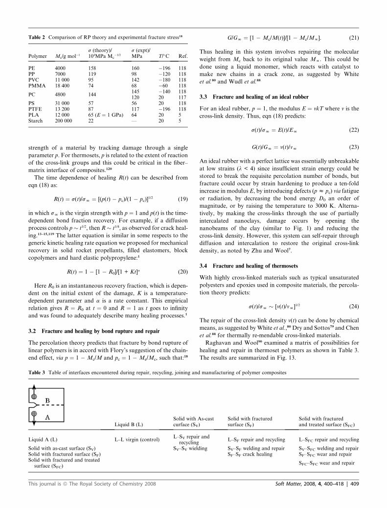
Table 2 Comparison of RP theory and experimental fracture stress18
Polymer Mc/g mol�1
s (theory)/104MPa Mc
�1/2
s (expt)/MPa T/�C Ref.
PE 4000 158 160 �196 118PP 7000 119 98 �120 118PVC 11 000 95 142 �180 118PMMA 18 400 74 68 �60 118
PC 4800 144145 �140 118120 20 117
PS 31 000 57 56 20 118PTFE 13 200 87 117 �196 118PLA 12 000 65 (E ¼ 1 GPa) 64 20 5Starch 200 000 22 — 20 5
strength of a material by tracking damage through a single
parameter p. For thermosets, p is related to the extent of reaction
of the cross-link groups and this could be critical in the fiber–
matrix interface of composites.120
The time dependence of healing R(t) can be described from
eqn (18) as:
R(t) ¼ s(t)/sN ¼ [(p(t) � pc)/(1 � pc)]1/2 (19)
in which sN is the virgin strength with p ¼ 1 and p(t) is the time-
dependent bond fraction recovery. For example, if a diffusion
process controls p � t1/2, then R � t1/4, as observed for crack heal-
ing.13–15,119 The latter equation is similar in some respects to the
generic kinetic healing rate equation we proposed for mechanical
recovery in solid rocket propellants, filled elastomers, block
copolymers and hard elastic polypropylene:1
R(t) ¼ 1 � [1 � R0]/[1 + Kt]a (20)
Here R0 is an instantaneous recovery fraction, which is depen-
dent on the initial extent of the damage, K is a temperature-
dependent parameter and a is a rate constant. This empirical
relation gives R ¼ R0 at t ¼ 0 and R ¼ 1 as t goes to infinity
and was found to adequately describe many healing processes.1
3.2 Fracture and healing by bond rupture and repair
The percolation theory predicts that fracture by bond rupture of
linear polymers is in accord with Flory’s suggestion of the chain-
end effect, via p ¼ 1 � Mc/M and pc ¼ 1 � Me/Mc, such that:18
Table 3 Table of interfaces encountered during repair, recycling, joining and
Liquid B (L)Solid with Acurface (SV
Liquid A (L) L–L virgin (control)L–SV repair
recyclingSolid with as-cast surface (SV) SV–SV wieldSolid with fractured surface (SF)Solid with fractured and treated
surface (SFC)
This journal is ª The Royal Society of Chemistry 2008
G/GN ¼ [1 � Mc/M(t)]/[1 � Mc/Mf]. (21)
Thus healing in this system involves repairing the molecular
weight from Mc back to its original value Mf. This could be
done using a liquid monomer, which reacts with catalyst to
make new chains in a crack zone, as suggested by White
et al.80 and Wudl et al.88
3.3 Fracture and healing of an ideal rubber
For an ideal rubber, p ¼ 1, the modulus E ¼ vkT where v is the
cross-link density. Thus, eqn (18) predicts:
s(t)/sN ¼ E(t)/EN (22)
G(t)/GN ¼ v(t)/vN (23)
An ideal rubber with a perfect lattice was essentially unbreakable
at low strains (l < 4) since insufficient strain energy could be
stored to break the requisite percolation number of bonds, but
fracture could occur by strain hardening to produce a ten-fold
increase in modulus E, by introducing defects (p z pc) via fatigue
or radiation, by decreasing the bond energy D0 an order of
magnitude, or by raising the temperature to 3000 K. Alterna-
tively, by making the cross-links through the use of partially
intercalated nanoclays, damage occurs by opening the
nanobeams of the clay (similar to Fig. 1) and reducing the
cross-link density. However, this system can self-repair through
diffusion and intercalation to restore the original cross-link
density, as noted by Zhu and Wool7.
3.4 Fracture and healing of thermosets
With highly cross-linked materials such as typical unsaturated
polyesters and epoxies used in composite materials, the percola-
tion theory predicts:
s(t)/sN � [v(t)/vN]1/2 (24)
The repair of the cross-link density v(t) can be done by chemical
means, as suggested by White et al.,80 Dry and Sottos79 and Chen
et al.88 for thermally re-mendable cross-linked materials.
Raghavan and Wool90 examined a matrix of possibilities for
healing and repair in thermoset polymers as shown in Table 3.
The results are summarized in Fig. 13.
manufacturing of polymer composites
s-cast)
Solid with fracturedsurface (SF)
Solid with fracturedand treated surface (SFC)
andL–SF repair and recycling L–SFC repair and recycling
ing SV–SF welding and repair SV–SFC welding and repairSF–SF crack healing SF–SFC wear and repair
SFC–SFC wear and repair
Soft Matter, 2008, 4, 400–418 | 409
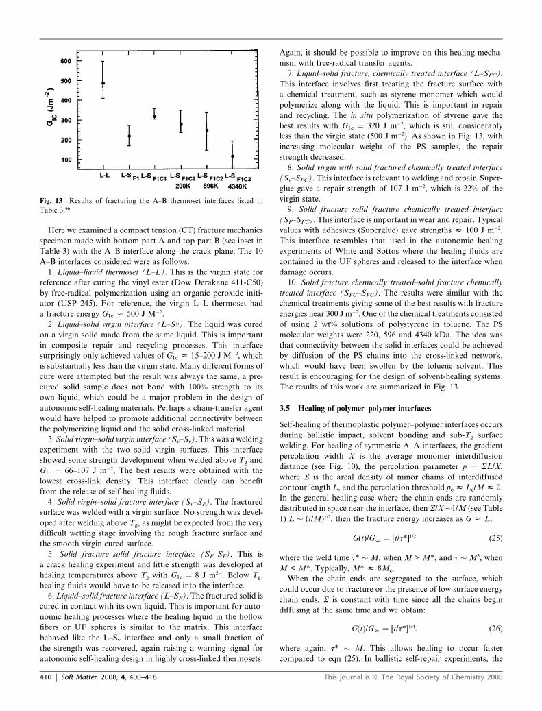
Fig. 13 Results of fracturing the A–B thermoset interfaces listed in
Table 3.90
Here we examined a compact tension (CT) fracture mechanics
specimen made with bottom part A and top part B (see inset in
Table 3) with the A–B interface along the crack plane. The 10
A–B interfaces considered were as follows:
1. Liquid–liquid thermoset (L–L). This is the virgin state for
reference after curing the vinyl ester (Dow Derakane 411-C50)
by free-radical polymerization using an organic peroxide initi-
ator (USP 245). For reference, the virgin L–L thermoset had
a fracture energy G1c z 500 J M�2.
2. Liquid–solid virgin interface (L–Sv). The liquid was cured
on a virgin solid made from the same liquid. This is important
in composite repair and recycling processes. This interface
surprisingly only achieved values of G1c z 15–200 J M�2, which
is substantially less than the virgin state. Many different forms of
cure were attempted but the result was always the same, a pre-
cured solid sample does not bond with 100% strength to its
own liquid, which could be a major problem in the design of
autonomic self-healing materials. Perhaps a chain-transfer agent
would have helped to promote additional connectivity between
the polymerizing liquid and the solid cross-linked material.
3. Solid virgin–solid virgin interface (Sv–Sv). This was a welding
experiment with the two solid virgin surfaces. This interface
showed some strength development when welded above Tg and
G1c ¼ 66–107 J m�2, The best results were obtained with the
lowest cross-link density. This interface clearly can benefit
from the release of self-healing fluids.
4. Solid virgin–solid fracture interface (Sv–SF). The fractured
surface was welded with a virgin surface. No strength was devel-
oped after welding above Tg, as might be expected from the very
difficult wetting stage involving the rough fracture surface and
the smooth virgin cured surface.
5. Solid fracture–solid fracture interface (SF–SF). This is
a crack healing experiment and little strength was developed at
healing temperatures above Tg with G1c ¼ 8 J m2�. Below Tg,
healing fluids would have to be released into the interface.
6. Liquid–solid fracture interface (L–SF). The fractured solid is
cured in contact with its own liquid. This is important for auto-
nomic healing processes where the healing liquid in the hollow
fibers or UF spheres is similar to the matrix. This interface
behaved like the L–Sv interface and only a small fraction of
the strength was recovered, again raising a warning signal for
autonomic self-healing design in highly cross-linked thermosets.
410 | Soft Matter, 2008, 4, 400–418
Again, it should be possible to improve on this healing mecha-
nism with free-radical transfer agents.
7. Liquid–solid fracture, chemically treated interface (L–SFC).
This interface involves first treating the fracture surface with
a chemical treatment, such as styrene monomer which would
polymerize along with the liquid. This is important in repair
and recycling. The in situ polymerization of styrene gave the
best results with G1c ¼ 320 J m�2, which is still considerably
less than the virgin state (500 J m�2). As shown in Fig. 13, with
increasing molecular weight of the PS samples, the repair
strength decreased.
8. Solid virgin with solid fractured chemically treated interface
(Sv–SFC). This interface is relevant to welding and repair. Super-
glue gave a repair strength of 107 J m�2, which is 22% of the
virgin state.
9. Solid fracture–solid fracture chemically treated interface
(SF–SFC). This interface is important in wear and repair. Typical
values with adhesives (Superglue) gave strengths z 100 J m�2.
This interface resembles that used in the autonomic healing
experiments of White and Sottos where the healing fluids are
contained in the UF spheres and released to the interface when
damage occurs.
10. Solid fracture chemically treated–solid fracture chemically
treated interface (SFC–SFC). The results were similar with the
chemical treatments giving some of the best results with fracture
energies near 300 J m�2. One of the chemical treatments consisted
of using 2 wt% solutions of polystyrene in toluene. The PS
molecular weights were 220, 596 and 4340 kDa. The idea was
that connectivity between the solid interfaces could be achieved
by diffusion of the PS chains into the cross-linked network,
which would have been swollen by the toluene solvent. This
result is encouraging for the design of solvent-healing systems.
The results of this work are summarized in Fig. 13.
3.5 Healing of polymer–polymer interfaces
Self-healing of thermoplastic polymer–polymer interfaces occurs
during ballistic impact, solvent bonding and sub-Tg surface
welding. For healing of symmetric A–A interfaces, the gradient
percolation width X is the average monomer interdiffusion
distance (see Fig. 10), the percolation parameter p ¼ SL/X,
where S is the areal density of minor chains of interdiffused
contour length L, and the percolation threshold pc z Lc/M z 0.
In the general healing case where the chain ends are randomly
distributed in space near the interface, then S/X �1/M (see Table
1) L � (t/M)1/2, then the fracture energy increases as G z L,
G(t)/GN ¼ [t/t*]1/2 (25)
where the weld time t* � M, when M > M*, and t � M3, when
M < M*. Typically, M* z 8Mc.
When the chain ends are segregated to the surface, which
could occur due to fracture or the presence of low surface energy
chain ends, S is constant with time since all the chains begin
diffusing at the same time and we obtain:
G(t)/GN ¼ [t/t*]1/4. (26)
where again, t* � M. This allows healing to occur faster
compared to eqn (25). In ballistic self-repair experiments, the
This journal is ª The Royal Society of Chemistry 2008
time t* is temperature dependent and the needed time for healing
competes with the cool-down process.
When using healing fluids with monomers that are different
than the matrix monomers, one can encounter an asymmetric,
potentially incompatible interface. For asymmetric incompatible
A–B interfaces of width d � c�1/2, where c is the Flory–Huggins
interaction parameter, we have again the percolation parameter
for the diffuse interface as p ¼ SL/X. In this case, X � d, L � d2,
and S is constant such that p � d. Since the fracture energy G �[d � dc], where dc is the tube diameter, then the fracture energy
depends on the normalized width w ¼ d/dc as,17
G(t)/GN ¼ [w(t) � 1]/[wN � 1] (27)
The latter relation is supported by experimental data on a wide
range of A–B interfaces, which were analyzed by Benkoski
et al.39 and Cole et al.40
Incompatible A–B interfaces are typically quite weak
compared to welded homopolymers. To make such interfaces
stronger, they can be reinforced with A–B co-polymer compa-
tiblizer chains, as demonstrated by Brown and co-workers41–48
Thus, one could incorporate compatibilizers into the healing
fluid, which when released would have sufficient mobility, e.g.
in a solvent, to heal the interface. For incompatible A–B inter-
faces reinforced by an areal density S of A–B compatibilizer
chains, an equilibrium diffuse interface is formed in which L
and X are constant, such that the percolation parameter p � S
and pc � Sc. Thus, the fracture energy as a function of areal
chain density becomes:17
G(t)/GN ¼ [S(t) � Sc]/[SN � Sc] (28)
The above connectivity relations for polymer interfaces are in
accord with much data obtained by several groups39–48 and are
reviewed in ref. 1 and 17. They provide the keys to understanding
damage evolution in fracture and its converse, healing.
3.6 Fatigue healing
For healing of thermoplastic interfaces the total interpenetration
of chains (X approaches Rg) is not necessary to achieve complete
strength when M > M* and t* < Tr. It is only necessary to diffuse
a distance equivalent to the radius of gyration of M*. However,
a word of caution: while complete strength may be obtained in
terms of critical fracture measures such as G1c and K1c , the dura-
bility, measured in sub-critical fracture terms, such as the fatigue
crack propagation rate da/dN, may be very far from its fully
healed state at t*. We have shown that while the weld toughness
K1c increases linearly with interdiffusion depth X, as K1c � X, the
fatigue crack propagation behavior of partially healed welds
behaves as:21
da/dN � X�5 (29)
which is a very strong function of interdiffusion and underscores
the penalty to pay for partial welding. Thus, the weld strength
may be near, or at the virgin strength, but the fatigue strength
may be dramatically reduced below its maximum value. Thus,
one should always design a healing time with respect to Tr to
achieve maximum durability of welds and interfaces. This is
This journal is ª The Royal Society of Chemistry 2008
a rather subtle processing point, which is often not appreciated
by the manufacturing industry and is important for self-healing
design, namely that fatigue and strength are related but not
similar in terms of healing parameters.
In fatigue of materials in general with applied stress sapp < sc,
the percolation theory suggests a new approach as follows: the
lifetime t occurs when the initial fraction of bonds pi is reduced
to pf, such that fracture occurs at the applied stress in accord
with eqn (18) as:
sapp ¼ {2ED0v[pf � pc]}1/2 (30)
This gives the critical bond fraction pf for the applied stress as
pf ¼ pc + sapp2/{2ED0v] (31)
The time dependence of p can be deduced from a steady-state
bond-fracture concept via
Pf ¼ pi � t(dp/dt) (32)
such that the failure time t is the time required to reduce pi to pfat the prevailing breakage rate dp/dt. The rate of bond rupture
dp/dt can be given by a thermally activated state theory
(reviewed in ref. 119) as:
dp/dt ¼ (1/t0)exp(�Do[1 � sapp/sc]/kT) (33)
in which the energy for bond fracture D0 is linearly reduced by
the applied stress. Substituting for dp/dt and pf and solving for
t, we obtain the lifetime of the material as:
t ¼ t0{[pi � pc] � sapp2/(2ED0v)}exp(D0[1 � sapp/sc]/kT) (34)
where D0/kT z 133 at room temperature and t0 z 10�12 s is the
vibrational period for the bonds being broken. For a material
without defects, pi ¼ 1 and sc is determined from eqn (18) using
pf¼ 1. Note that the applied stress enters in both the front factor
and exponential factor for t. When the applied stresses are small,
the exponential factors dominate and the ratio of two lifetimes at
applied stresses s1 and s2 would be:
t1/t2 ¼ exp[(s2 � s1)/sc]D0/kT (35)
When the damaged bond fraction is restored by self-repair
processes such that pi/ 1 in eqn (34), the material is rejuvenated
and its lifetime is considerably extended. Thus, in Fig. 7, we see
that the healing fluids allowed the initial pre-crack to be
completely healed (pi / 1) and that during fatigue, the self-
healing fluids retarded the crack advance compared to the
control as the rate of bond rupture dp/dt was reduced.
4 The hard-to-soft matter transition
4.1 Twinkling fractal theory of Tg
A topic that is most relevant to this discussion on self-healing is
the fundamental understanding of the hard-to-soft and soft-to-
hard matter transition, typically called the glass transition. The
glass transition temperature Tg is arrived at by heating a hard
cold glassy material to a suitable temperature Tg whereby it
Soft Matter, 2008, 4, 400–418 | 411
becomes soft; or by providing sufficient mechanical energy to
make the material flow by yielding; or by making the sample
dimensions sufficiently small, typically nanoscale where the Tg
drops considerably; or by examining the top layer of a solid
sample at T < Tg, where it appears to have a mobile layer; or
by increasing the cross-link density; or by changing molecular
weight or by removing a solvent, etc. We could ask whether it
is possible to get thermally induced self-healing below Tg, or
how does Tg affect the design of our chemically cross-linking
system? Can we change the nature of the material by the rate
at which we explore it, such as in liquid armor114 where a very
soft cloth-like material turns to apparent steel at high rates of
impact. Conversely, how do we utilize impact energy to change
a hard material to a soft material, which can self-heal, as in
the ballistic healing experiments?
An understanding of the glass transition remains as one of the
unsolved problems in the physics community, as discussed by
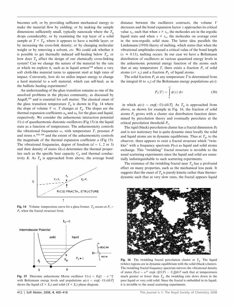
Angell,121 and is essential for soft matter. The classical onset of
the glass transition temperature Tg is shown in Fig. 14 where
the slope of volume V vs. T changes at Tg. The slopes are the
thermal expansion coefficients ag and aL for the glass and liquid,
respectively. We consider the anharmonic interaction potential
U(x) of quasiharmonic diatomic oscillators (Fig 15) in the liquid
state as a function of temperature. The anharmonicity controls
the vibrational frequencies u, with temperature T, pressure P
and stress s,122–124 and the extent of the anharmonicity controls
the magnitude of the thermal expansion coefficient a (Fig 15).
The vibrational frequencies, degree of freedom (d ¼ 1, 2 or 3)
and their density of states G(u) determines the thermal proper-
ties such as the specific heat capacity Cp and thermal conduc-
tivity K. As Tg is approached from above, the average bond
Fig. 14 Volume–temperature curve for a glass former. Tg occurs at Ps ¼Pc when the fractal structure form.
Fig. 15 Diatomic anharmonic Morse oscillator U(x) ¼ D0[1 � e�ax]2
with Boltzmann energy levels and populations 4(x) � exp[�U(x)/kT]
shows the liquid (X > Xc) and solid (X < Xc) phase diagram.
412 | Soft Matter, 2008, 4, 400–418
distance between the oscillators contracts, the volume V
decreases and the bond expansion factor x approaches its critical
value xc, such that when x > xc, the molecules are in the ergodic
liquid state and when x < xc, the molecules on average exist
in the non-ergodic solid state. The latter idea parallels the
Lindemann (1910) theory of melting, which states that when the
vibrational amplitudes exceed a critical value of the bond length
(x z 0.11), melting occurs. In our case we have a Boltzmann
distribution of oscillators at various quantized energy levels in
the anharmonic potential energy function of the atoms such
that at any temperature T, there exists a fraction Ps of solid
atoms (x< xc) and a fraction PL of liquid atoms.
The solid fraction Ps at any temperature T is determined from
the integral (0 to xc) of the Boltzmann energy populations 4(x):
PsðTÞ ¼ðxc
0
fðxÞ dx (36)
in which 4(x) � exp[�U(x)/kT]. As Tg is approached from
above, as shown for example in Fig. 16, the fraction of solid
atoms Ps grows with a cluster size distribution function deter-
mined by percolation theory and eventually percolates at the
critical percolation threshold Pc.
The rigid (black) percolation cluster has a fractal dimension Df
and is not stationary but is quite dynamic since locally the solid
and liquid atoms are in dynamic equilibrium. Thus at Tg, to the
observer, there appears to exist a fractal structure which ‘‘twin-
kles’’ with a frequency spectrum F(u) as liquid and solid atoms
exchange. This ‘‘twinkling’’ fractal structure is invisible to the
usual scattering experiments since the liquid and solid are essen-
tially indistinguishable to such scattering experiments.
The existence of the twinkling fractal near Tg has a profound
effect on many properties, such as the mechanical loss peak. It
suggests that the onset of Tg is purely kinetic rather than thermo-
dynamic such that at very slow rates, the fractal appears liquid
Fig. 16 The twinkling fractal percolation cluster at Tg. The liquid
(white) regions are in dynamic equilibrium with the solid (black) clusters.
The twinkling fractal frequency spectrum mirrors the vibrational density
of states F(u) � uDf�1exp(�[|U(T) � Uc|])/kT such that at temperatures
much greater or lower than Tg, the twinkling rate slows down in the
pure liquid or very cold solid. Since the fractal is embedded in its liquid,
it is invisible to the usual scattering experiments.
This journal is ª The Royal Society of Chemistry 2008
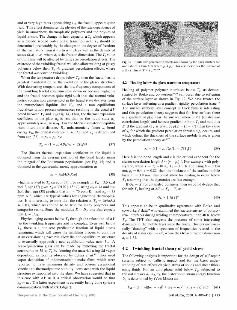
Fig. 17 Finite size percolation effects are shown by the dark clusters for
one side of a thin film where p < pc. This also describes the surface of
a thick film at T < Tg.126–129
and at very high rates approaching u0, the fractal appears quite
rigid. This effect dominates the physics of the rate dependence of
yield in amorphous thermoplastic polymers and the physics of
liquid armor. The change in heat capacity DCp which appears
as a pseudo second order phase transition near Tg should be
determined predictably by the changes in the degree of freedom
of the oscillators from d ¼3 to d ¼ Df as well as the density of
states G(u)� udf, where df is the fracton dimension. The Tg value
of thin films will be affected by finite size percolation effects. The
existence of the twinkling fractal will also allow welding of glassy
polymers below their Tg via gradient percolation effects, where
the fractal danceswhile twinkling.
When the temperature drops below Tg, then the fractal has its
greatest manifestation on the evolution of the glassy structure.
With decreasing temperature, the low frequency components of
the twinkling fractal spectrum slow down or become negligible
and the fractal becomes quite rigid such that the normal volu-
metric contraction experienced in the liquid state deviates from
the extrapolated liquidus line VN and a non equilibrium
fractal-cavitation process commences resulting in the usual DV
noted between Vg and VN(Fig. 14) Thus, the thermal expansion
coefficient in the glass ag is less than in the liquid state aLapproximately as ag z pcaL. For the Morse oscillator of equilib-
rium interatomic distance R0, anharmonicity factor a, bond
energy D0, the critical distance xc z 1/3a and Tg is determined
from eqn (36), at pc ¼ ps, by:
Tg z (1 � pc)4D0/9k z 2D0/9k (37)
The (linear) thermal expansion coefficient in the liquid is
obtained from the average position of the bond length using
the integral of the Boltzmann populations (see Fig. 15) and is
obtained in the quasi-anharmonic approximation as:
aL ¼ 3k/[4D0R0a] (38)
which is related to Tg via eqn (37). For example, if D0 ¼ 3.5 kcal
mol�1, eqn (37) gives Tg¼ 391 K (118 �C); using R0¼ 3A and a ¼2/A, then eqn (38) predicts that aL z 70 ppm K�1 and ag z 35
ppm K�1, which are typical values for engineering thermoplas-
tics. It is interesting to note that the relation aLTg ¼ 1/(6aR0)
z 0.03, which was found to be true for many polymers and
composite resins. Since the modulus E � D0, one also expects
that E � 1/aL.
Physical aging occurs below Tg through the relaxation of DV
via the twinkling frequencies and is complex. Even well below
Tg, there is a non-zero predictable fraction of liquid atoms
remaining, which will cause the twinkling process to continue
at an ever-slowing pace but allow the non-equilibrium structure
to eventually approach a new equilibrium value near VN. A
near-equilibrium glass can be made by removing the fractal
constraints in 3d at Tg by forming the material using 2d vapor
deposition, as recently observed by Ediger et al.125 They used
vapor deposition of indometracin to make films, which were
reported to have maximum density and possess exceptional
kinetic and thermodynamic stability, consistent with the liquid
structure extrapolated into the glass. We have suggested that in
this case with DV z 0, a critical observation would be that
ag ¼ aL. The latter experiment is currently being done (private
communication with Mark Ediger).
This journal is ª The Royal Society of Chemistry 2008
4.2 Healing below the glass transition temperature
Healing of polymer–polymer interfaces below Tg, as demon-
strated by Boiko and co-workers67,68 can occur due to softening
of the surface layer as shown in Fig. 17. We have treated the
surface layer softening as a gradient rigidity percolation issue.17
The surface rubbery layer concept in thick films is interesting
and this percolation theory suggests that for free surfaces there
is a gradient of p(x) near the surface, where x < x (cluster size
correlation length) and hence a gradient in both Tg and modulus
E. If the gradient of p is given by p(x) ¼ (1 � x/x) then the value
of xc for which the gradient percolation threshold pc occurs, and
which defines the thickness of the surface mobile layer, is given
by the percolation theory as5,17
xc ¼ b(1 � pc)/{pcv[1 � T/Tg]
v} (39)
Here b is the bond length and n is the critical exponent for the
cluster correlation length x � [p � pc]�n. For example with poly-
styrene, when T ¼ Tg �10 K, Tg ¼ 373 K and using b ¼ 0.154
nm, pc ¼ 0.4, n ¼ 0.82, then the thickness of the surface mobile
layer xc ¼ 3.8 nm. This could allow for healing to occur below
Tg assuming that the dynamics are fast enough.
If G1c � X2 for entangled polymers, then we could deduce that
for sub Tg healing at DT ¼ Tg � T, as
G1c � [1/DT]2n (40)
This appears to be in qualitative agreement with Boiko and
co-workers’ data68 who examined the fracture energy of polysty-
rene interfaces during welding at temperatures up to 40 K below
Tg. The TFT also suggests the presence of some interesting
dynamics in the mobile layer since the fractal clusters are essen-
tially ‘‘dancing’’ with a spectrum of frequencies related to the
density of states G(u) � udf, where the Orbach fracton dimension
df ¼ 1.33.
4.2 Twinkling fractal theory of yield stress
The following analysis is important for the design of self-repair
systems subject to ballistic impact and for the basic under-
standing of rate effects on yield stress of solids and shear thick-
ening fluids. For an amorphous solid below Tg, subjected to
triaxial stresses s1, s2, s3, the distortional strain energy function
Ud is determined by (Von Mises) as:
Ud ¼ (1 + n)[(s1 � s2)2 + (s2 � s3)
2 + (s2 � s3)2]/6E (41)
Soft Matter, 2008, 4, 400–418 | 413
in which n is the Poisson ratio and E is the isotropic elastic
Young’s modulus. In the simple uniaxial case, we obtain the
stored strain energy from eqn (41) with n ¼ 0.5 as U ¼ s2/2E.
This stored energy must be utilized to overcome a percolation
number of interatomic anharmonic oscillator bonds of energy
U(xc). For a Morse oscillator U(xc) ¼ 0.08 D0, which is the
energy necessary to reach the Lindemann bond expansion at
xc. The number of such oscillators per unit volume is 1/Vm,
where Vm is the molar volume. At the critical stored energy,
we have yielding when the amorphous solid is raised to the twin-
kling fractal state by the release of the mechanical energy and
flow begins in accord with:
sy2/2E $ 0.08 D0 [ps � pc]/Vm (42)
in which the solid fraction ps is given by eqn (36) and is both
temperature and rate dependent. Thus, the yield stress is
obtained as:123,124
sy ¼ {0.16E[ps � pc]D0/Vm}1/2 (43)
Note that the term D0/Vm corresponds to the traditional cohesive
energy density. For example, if E ¼ 1 GPa, p ¼ 1 (high rate of
deformation), pc ¼ 1/2, D0 ¼ 3 kcal mol�1, Vm ¼ 2M0/r, r ¼ 1
g cc�1, the monomer molecular weight M0 ¼ 100 g mol�1, then
eqn (43) predicts that sY ¼ 71 MPa. This value is typical for
high performance amorphous polymers with Tg z 63 �C.
The magnitude of ps is also rate and temperature dependent in
a manner determined by the twinkling fractal density of states.
As T approaches Tg from below, ps decreases towards pc and sydecreases accordingly. At high rates of deformation, p increases
and sy increases. At low rates of deformation, p decreases
towards pc and this is the basis for designing liquid armor with
shear-thickening fluids, which are liquid layers with particles at
p > pc that turn into solids at high rates. Thus, ps(g) � [g/u0]df
such that we can express eqn (43) as
sY/sN ¼ {[(g/u0)df � pc]/[1 � pc]}
1/2 (44)
in which sN is the yield stress at g ¼ u0. There exists a critical
deformation rate given by
gc ¼ u0pc (45)
such that when g < gc, then the material is liquid-like and when g
> gc, then the yield stress increases from zero to its maximum
value at u0. Thus, the yield stress increases with rate of testing
and the higher the rate, the more stored energy is required, which
facilitates ballistic healing at high rates.
The TFT concept of Tg suggests that twinkling fractal cluster
at Tg is quite soft, especially when sensed at low rates of
deformation. One can immediately understand why the loss
tangent tand ¼ E’’/E’(loss/storage modulus) reaches its
maximum value near Tg. The twinkling fractal frequencies are
given by
F(u) � udfexp�[|U(T) �Uc|]/kT (46)
Here the first term udf is the vibrational density of states for
a cluster of frequency u and the second exponential term is the
414 | Soft Matter, 2008, 4, 400–418
probability that the vibration will cause a ‘‘twinkle’’ or change
from solid to liquid or visa versa. Note that this energy difference
is always positive and is behaves as |U(T) � Uc| � [T2 � Tc2]. In
a single mechanical cycle, the stored energy is released or dissi-
pated by the twinkling process as liquid and solid clusters of
frequency u exchange at the fastest rates in accord with the
density of states G(u) � udf. As the temperature drops below
Tg, the percolating cluster increases in mass and the stored
energy increases. However, the twinkling frequencies decrease
their rate due to the increased energy barrier DE ¼ |U(T) � Uc|
for the solid-to-liquid transition and the energy dissipation
decreases. Near Tg, we can approximate the temperature depen-
dence of U(x) for a Morse oscillator as U(T) z a2D0a2T2, such
that the temperature dependence of F(u) is:
F(u,T) ¼ udfexp�[b(T2 � Tg2)/kT] (47)
in which the constant b ¼ a2D0a2. Thus the activation energy DE
is temperature dependent approximately as DE � [(T/Tg)2 � 1]
and changes rapidly with T. When T > Tg, the rigid clusters
decrease, the stored energy decreases and the rate of liquid-to-
solid transitions decreases. Thus, tand will reach a maximum
value near Tg typically. The twinkling fractal, though invisible
to scattering experiments could be the ‘‘dynamics engine’’ of
the amorphous state and plays an important role in complex
processes such as physical aging and self-healing.
5. Present and future advances in self-healingmaterials
A new self-healing system that mimics a vascular healing system
in skin was developed by the Sottos–White group at the Univer-
sity of Illinois, using a micro-fluidics variant on their earlier
liquid sphere system as shown in Fig. 18.84 The advantage of
this system over their earlier self-healing models, is that the
embedded vascular system would allow multiple healing events
to occur. The encapsulated spheres were limited to one healing
event per crack. In the above case, cracks initiated in bending
cause damage to the top coating (skin) which propagate and
arrest at the coating–substrate interface (Fig 18c). The healing
fluid in the micro fluidic channels then wicks up the crack to
the surface through capillary action. The fluid makes contact
with the epoxy skin, which contains the polymerizing agent
and the liquid-to-solid polymerization reaction is initiated.
They found that the healing fluid dicyclopentadiene (DCPD)
worked well with a Grubb’s catalyst, benzylidene bis(tricyclo-
hexylphosphine)dichloro ruthenium. This system has sufficiently
low viscosity to allow facile flow to the skin surface and the cata-
lyst remains active both during and after the reaction. The
authors successfully demonstrated that they could reheal the
skin layer seven different times.
In related experiments, White and Sottos et al. (private
communication) have found that in epoxy matrices, the DCPD
healing fluids along with the Grubb’s catalyst could be replaced
with a simple non-reactive solvent that was compatible with the
epoxy. This is essentially a solvent healing system using the
autonomic or microfluidic delivery system. It is remarkable
that high levels of healing can be obtained in highly cross-linked
polymers using just solvents alone. The new solvent system will
This journal is ª The Royal Society of Chemistry 2008
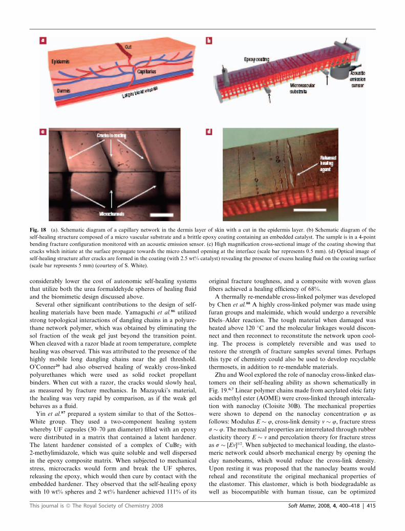
Fig. 18 (a). Schematic diagram of a capillary network in the dermis layer of skin with a cut in the epidermis layer. (b) Schematic diagram of the
self-healing structure composed of a micro vascular substrate and a brittle epoxy coating containing an embedded catalyst. The sample is in a 4-point
bending fracture configuration monitored with an acoustic emission sensor. (c) High magnification cross-sectional image of the coating showing that
cracks which initiate at the surface propagate towards the micro channel opening at the interface (scale bar represents 0.5 mm). (d) Optical image of
self-healing structure after cracks are formed in the coating (with 2.5 wt% catalyst) revealing the presence of excess healing fluid on the coating surface
(scale bar represents 5 mm) (courtesy of S. White).
considerably lower the cost of autonomic self-healing systems
that utilize both the urea formaldehyde spheres of healing fluid
and the biomimetic design discussed above.
Several other significant contributions to the design of self-
healing materials have been made. Yamaguchi et al.86 utilized
strong topological interactions of dangling chains in a polyure-
thane network polymer, which was obtained by eliminating the
sol fraction of the weak gel just beyond the transition point.
When cleaved with a razor blade at room temperature, complete
healing was observed. This was attributed to the presence of the
highly mobile long dangling chains near the gel threshold.
O’Conner20 had also observed healing of weakly cross-linked
polyurethanes which were used as solid rocket propellant
binders. When cut with a razor, the cracks would slowly heal,
as measured by fracture mechanics. In Mazayuki’s material,
the healing was very rapid by comparison, as if the weak gel
behaves as a fluid.
Yin et al.87 prepared a system similar to that of the Sottos–
White group. They used a two-component healing system
whereby UF capsules (30–70 mm diameter) filled with an epoxy
were distributed in a matrix that contained a latent hardener.
The latent hardener consisted of a complex of CuBr2 with
2-methylimidazole, which was quite soluble and well dispersed
in the epoxy composite matrix. When subjected to mechanical
stress, microcracks would form and break the UF spheres,
releasing the epoxy, which would then cure by contact with the
embedded hardener. They observed that the self-healing epoxy
with 10 wt% spheres and 2 wt% hardener achieved 111% of its
This journal is ª The Royal Society of Chemistry 2008
original fracture toughness, and a composite with woven glass
fibers achieved a healing efficiency of 68%.
A thermally re-mendable cross-linked polymer was developed
by Chen et al.88 A highly cross-linked polymer was made using
furan groups and maleimide, which would undergo a reversible
Diels–Alder reaction. The tough material when damaged was
heated above 120 �C and the molecular linkages would discon-
nect and then reconnect to reconstitute the network upon cool-
ing. The process is completely reversible and was used to
restore the strength of fracture samples several times. Perhaps
this type of chemistry could also be used to develop recyclable
thermosets, in addition to re-mendable materials.
Zhu and Wool explored the role of nanoclay cross-linked elas-
tomers on their self-healing ability as shown schematically in
Fig. 19.6,7 Linear polymer chains made from acrylated oleic fatty
acids methyl ester (AOME) were cross-linked through intercala-
tion with nanoclay (Cloisite 30B). The mechanical properties
were shown to depend on the nanoclay concentration 4 as
follows: Modulus E � 4, cross-link density v � 4, fracture stress
s� 4. The mechanical properties are interrelated through rubber
elasticity theory E � v and percolation theory for fracture stress
as s � [Ev]1/2. When subjected to mechanical loading, the elasto-
meric network could absorb mechanical energy by opening the
clay nanobeams, which would reduce the cross-link density.
Upon resting it was proposed that the nanoclay beams would
reheal and reconstitute the original mechanical properties of
the elastomer. This elastomer, which is both biodegradable as
well as biocompatible with human tissue, can be optimized
Soft Matter, 2008, 4, 400–418 | 415
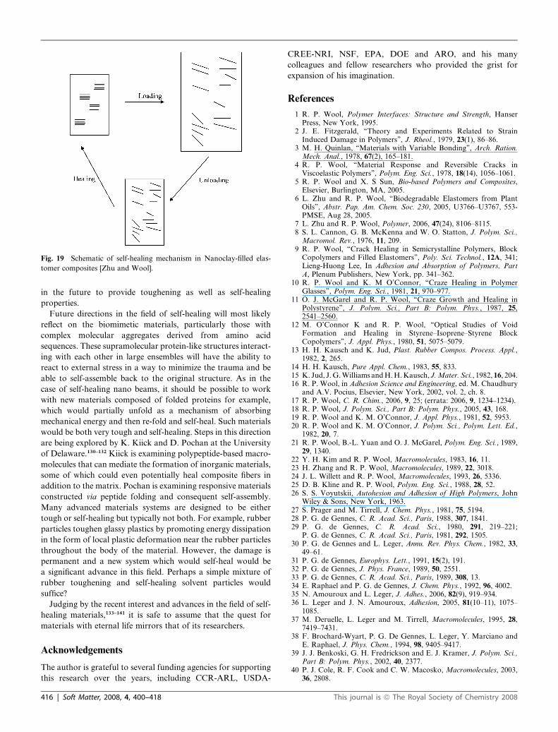
Fig. 19 Schematic of self-healing mechanism in Nanoclay-filled elas-
tomer composites [Zhu and Wool].
in the future to provide toughening as well as self-healing
properties.
Future directions in the field of self-healing will most likely
reflect on the biomimetic materials, particularly those with
complex molecular aggregates derived from amino acid
sequences. These supramolecular protein-like structures interact-
ing with each other in large ensembles will have the ability to
react to external stress in a way to minimize the trauma and be
able to self-assemble back to the original structure. As in the
case of self-healing nano beams, it should be possible to work
with new materials composed of folded proteins for example,
which would partially unfold as a mechanism of absorbing
mechanical energy and then re-fold and self-heal. Such materials
would be both very tough and self-healing. Steps in this direction
are being explored by K. Kiick and D. Pochan at the University
of Delaware.130–132 Kiick is examining polypeptide-based macro-
molecules that can mediate the formation of inorganic materials,
some of which could even potentially heal composite fibers in
addition to the matrix. Pochan is examining responsive materials
constructed via peptide folding and consequent self-assembly.
Many advanced materials systems are designed to be either
tough or self-healing but typically not both. For example, rubber
particles toughen glassy plastics by promoting energy dissipation
in the form of local plastic deformation near the rubber particles
throughout the body of the material. However, the damage is
permanent and a new system which would self-heal would be
a significant advance in this field. Perhaps a simple mixture of
rubber toughening and self-healing solvent particles would
suffice?
Judging by the recent interest and advances in the field of self-
healing materials,133–141 it is safe to assume that the quest for
materials with eternal life mirrors that of its researchers.
Acknowledgements
The author is grateful to several funding agencies for supporting
this research over the years, including CCR-ARL, USDA-
416 | Soft Matter, 2008, 4, 400–418
CREE-NRI, NSF, EPA, DOE and ARO, and his many
colleagues and fellow researchers who provided the grist for
expansion of his imagination.
References
1 R. P. Wool, Polymer Interfaces: Structure and Strength, HanserPress, New York, 1995.
2 J. E. Fitzgerald, ‘‘Theory and Experiments Related to StrainInduced Damage in Polymers’’, J. Rheol., 1979, 23(1), 86–86.
3 M. H. Quinlan, ‘‘Materials with Variable Bonding’’, Arch. Ration.Mech. Anal., 1978, 67(2), 165–181.
4 R. P. Wool, ‘‘Material Response and Reversible Cracks inViscoelastic Polymers’’, Polym. Eng. Sci., 1978, 18(14), 1056–1061.
5 R. P. Wool and X. S Sun, Bio-based Polymers and Composites,Elsevier, Burlington, MA, 2005.
6 L. Zhu and R. P. Wool, ‘‘Biodegradable Elastomers from PlantOils’’, Abstr. Pap. Am. Chem. Soc. 230, 2005, U3766–U3767, 553-PMSE, Aug 28, 2005.
7 L. Zhu and R. P. Wool, Polymer, 2006, 47(24), 8106–8115.8 S. L. Cannon, G. B. McKenna and W. O. Statton, J. Polym. Sci.,
Macromol. Rev., 1976, 11, 209.9 R. P. Wool, ‘‘Crack Healing in Semicrystalline Polymers, BlockCopolymers and Filled Elastomers’’, Poly. Sci. Technol., 12A, 341;Lieng-Huong Lee, In Adhesion and Absorption of Polymers, PartA, Plenum Publishers, New York, pp. 341–362.
10 R. P. Wool and K. M O’Connor, ‘‘Craze Healing in PolymerGlasses’’, Polym. Eng. Sci., 1981, 21, 970–977.
11 O. J. McGarel and R. P. Wool, ‘‘Craze Growth and Healing inPolystyrene’’, J. Polym. Sci., Part B: Polym. Phys., 1987, 25,2541–2560.
12 M. O’Connor K and R. P. Wool, ‘‘Optical Studies of VoidFormation and Healing in Styrene–Isoprene–Styrene BlockCopolymers’’, J. Appl. Phys., 1980, 51, 5075–5079.
13 H. H. Kausch and K. Jud, Plast. Rubber Compos. Process. Appl.,1982, 2, 265.
14 H. H. Kausch, Pure Appl. Chem., 1983, 55, 833.15 K. Jud, J.G.Williams andH.H.Kausch, J. Mater. Sci., 1982, 16, 204.16 R. P. Wool, in Adhesion Science and Engineering, ed. M. Chaudhury
and A.V. Pocius, Elsevier, New York, 2002, vol. 2, ch. 8.17 R. P. Wool, C. R. Chim., 2006, 9, 25; (errata: 2006, 9, 1234–1234).18 R. P. Wool, J. Polym. Sci., Part B: Polym. Phys., 2005, 43, 168.19 R. P. Wool and K. M. O’Connor, J. Appl. Phys., 1981, 52, 5953.20 R. P. Wool and K. M. O’Connor, J. Polym. Sci., Polym. Lett. Ed.,
1982, 20, 7.21 R. P. Wool, B.-L. Yuan and O. J. McGarel, Polym. Eng. Sci., 1989,
29, 1340.22 Y. H. Kim and R. P. Wool, Macromolecules, 1983, 16, 11.23 H. Zhang and R. P. Wool, Macromolecules, 1989, 22, 3018.24 J. L. Willett and R. P. Wool, Macromolecules, 1993, 26, 5336.25 D. B. Kline and R. P. Wool, Polym. Eng. Sci., 1988, 28, 52.26 S. S. Voyutskii, Autohesion and Adhesion of High Polymers, John
Wiley & Sons, New York, 1963.27 S. Prager and M. Tirrell, J. Chem. Phys., 1981, 75, 5194.28 P. G. de Gennes, C. R. Acad. Sci., Paris, 1988, 307, 1841.29 P. G. de Gennes, C. R. Acad. Sci., 1980, 291, 219–221;
P. G. de Gennes, C. R. Acad. Sci., Paris, 1981, 292, 1505.30 P. G. de Gennes and L. Leger, Annu. Rev. Phys. Chem., 1982, 33,
49–61.31 P. G. de Gennes, Europhys. Lett., 1991, 15(2), 191.32 P. G. de Gennes, J. Phys. France, 1989, 50, 2551.33 P. G. de Gennes, C. R. Acad. Sci., Paris, 1989, 308, 13.34 E. Raphael and P. G. de Gennes, J. Chem. Phys., 1992, 96, 4002.35 N. Amouroux and L. Leger, J. Adhes., 2006, 82(9), 919–934.36 L. Leger and J. N. Amouroux, Adhesion, 2005, 81(10–11), 1075–
1085.37 M. Deruelle, L. Leger and M. Tirrell, Macromolecules, 1995, 28,
7419–7431.38 F. Brochard-Wyart, P. G. De Gennes, L. Leger, Y. Marciano and
E. Raphael, J. Phys. Chem., 1994, 98, 9405–9417.39 J. J. Benkoski, G. H. Fredrickson and E. J. Kramer, J. Polym. Sci.,
Part B: Polym. Phys., 2002, 40, 2377.40 P. J. Cole, R. F. Cook and C. W. Macosko, Macromolecules, 2003,
36, 2808.
This journal is ª The Royal Society of Chemistry 2008
41 C. Creton, E. J. Kramer, H. R. Brown and C. Y. Hui, Adv. Polym.Sci., 2002, 156, 53.
42 H. R. Brown, Macromolecules, 1991, 24, 2752; H. R. Brown,Macromolecules, 2001, 34, 3720.
43 H. R. Brown, J. Mater. Sci., 1990, 25, 2791.44 C. Creton, E. J. Kramer, C.-Y. Hui and H. R. Brown,
Macromolecules, 1992, 25, 3075.45 C. Creton and E. J. Kramer, Macromolecules, 1991, 24, 1846.46 K. Cho, H. R. Brown and D. C. Miller, J. Polym. Sci., Part B:
Polym. Phys., 1990, 28, 1699.47 H. R. Brown, K. Char, V. R. Deline and P. F. Green,
Macromolecules, 1993, 26, 4155.48 K. Char, H. R. Brown and V. R. Deline, Macromolecules, 1993, 26,
4164.49 K. L. Anderson, J. T. Wescott, T. J. Carver and A. H. Windle,
‘‘Mesoscale Modeling of Polymer Welding’’, Mater. Sci. Eng., A,2004, 365(1-2), 14.
50 J. Rottler and M. O. Robbins, J. Adhes. Sci. Technol., 2003, 17(3),369.
51 R. P. Wool and J. M. Long, Macromolecules, 1993, 26, 5227.52 E. Helfand, Macromolecules, 1992, 25, 1676.53 V. Ganesan and V. Pryamitsyn, Macromolecules, 2002, 35, 9219.54 R. E. Gorga and B. Narasimhan, J. Polym. Sci., Part B: Polym.
Phys., 2002, 20, 2292.55 A. G. Mikos and N. A. Pappas, J. Chem. Phys., 1988, 88, 1337.56 M. McLeish, M. Plummer and A. Donald, Polymer, 1989, 30, 1651.57 R. P. Wool, D. Bailey and A. Friend, J. Adhes. Sci. Technol., 1996,
10, 305.58 H. P. Schreiber and A. Ouhlal, J. Adhes., 2003, 79(2), 141.59 R. Schnell, M. Stamm and C. Creton, Macromolecules, 1999, 32,
3240.60 Y. C. Wang and M. A. Winnik, Macromolecules, 1993, 26(12), 3147.61 J. N. Yoo, L. H. Sperling, C. J. Glinka and A. Klein,
Macromolecules, 1990, 23, 3962.62 N. Mohammadi, A. Klein and L. H. Sperling, Macromolecules,
1993, 26, 1019.63 M. Sambasivan, A. Klein and L. H. Sperling, J. Appl. Polym. Sci.,
1995, 58(2), 356–366.64 R. E. Robertson, in Toughness and Brittleness of Plastics, Adv.
Chem. Ser. 154, American Chemical Society, Washington, DC,1976.
65 E. J. Kramer, J. Mater. Sci., 1978, 14, 1381.66 F. Yang and R. Pitchumani, Macromolecules, 2002, 35, 3213.67 Y. M. Boiko, Mech. Compos. Mater., 2003, 31(1), 89.68 Y. M. Boiko, A. Bach and J. Lynaae-Jorgensen, J. Polym. Sci., Part
B: Polym. Phys., 2004, 42, 1861.69 I. Lee and R. P. Wool, J. Polym. Sci., Part B: Polym. Phys., 2002, 40,
2343–2353.70 I. Lee and R. P. Wool, Macromolecules, 2000, 33, 2680–2687.71 L. Gong, R. P. Wool, A. D. Friend and K. Goranov, J. Polym. Sci.,
Part A: Polym. Chem., 1999, 37, 3129–3137.72 L. Gong, A. D. Friend and R. P. Wool, Macromolecules, 1998,
31(11), 3706–3714.73 L. Gong and R. P. Wool, J. Adhes., 1999, 71, 189–209.74 L. Gong, PhD Thesis, ‘‘Polymer–Solid Interfaces: Structure and
Strength’’, University of Delaware, Newark DE, 1999.75 R. P. Wool and S. P. Bunker, J. Adhes., 2007, 83, 907–926.76 R. P. Wool, Macromolecules, 1993, 26, 1564.77 C. M. Dry, ‘‘Smart Building Materials Which Prevent Damage and
Repair Themselves, in Smart Materials Fabrication and Materialsfor Micro-Electro-Mechanical Systems, Symposium held April 28–30, 1992, San Francisco, CA, vol. 276 in series Materials ResearchSociety Proceedings, MRS Philadelphia, PA 331, (1992).
78 C. M. Dry, ‘‘Smart Materials which Sense, Activate and RepairDamage’’, in First European Conference on Smart Structures andMaterials, Glasgow, Scotland, ed. B. Culshaw, P. T. Gardiner andA. McDonach, vol. 1777 in series SPIE Proceedings, SPIE,Bellingham, WA 367 (1992).
79 C. M. Dry and N. Sottos, ‘‘Passive Smart Self-Repair in PolymerMatrix Composite Materials, in Smart Structures and Materials:Smart Materials, ed. V. K. Varadan, Proceedings of 1993 NorthAmerican SPIE Conference on Smart Structures and Materials, vol.1916 in series SPIE Proceedings, SPIE, Bellingham, WA, 438 (1993).
80 S. R. White, N. R. Sottos, P. H. Geubelle, J. S. Moore,M. R. Kessler, S. R. Sriram, E. N. Brown and S. Viswanathan,
This journal is ª The Royal Society of Chemistry 2008
‘‘Autonomic Healing of Polymer Composites’’, Nature, 2001,409(6822), 794–797.
81 E. N. Brown, N. R. Sottos and S. R. White, ‘‘Fracture Testing ofa Self-healing Polymer Composite, Exp. Mech., 2002, 42(4), 372–379.
82 E. N. Brown, S. R. White and N. R. Sottos, ‘‘Fatigue CrackPropagation in Microcapsule-toughened Epoxy, J. Mater. Sci.,2006, 41(18), 6266–6273.
83 M. R. Kessler, N. R. Sottos and S. R. White, ‘‘Self-healingStructural Composite Materials, Composites, Part A: Appl. Sci.Manuf., 2003, 34(8), 743–753.
84 K. S. Toohey, N. R. Sottos, J. A. Lewis, J. S. Moore andS. R. White, ‘‘Self-healing Materials with MicrovascularNetworks’’, Nat. Mater. Lett., 2007, 6(8), 581–585.
85 R. P. Wool, ‘‘A Material Fix’’, Nature, 2001, 409, 773.86 M. Yamaguchi, S. Ono and M. Terano, ‘‘Self Repairing Property of
Polymer Network with Dangling Chains’’, Mater. Lett., 2007, 61,1396–1399.
87 T. Yin, M. Z. Rong, M. Q. Zhang and G. C. Yang, ‘‘Self-healingEpoxy Composites – Preparation and Effect of the HealantConsisting of Microencapsulated Epoxy and Latent CuringAgent’’, Compos. Sci. Technol., 2007, 67(2), 201–212.
88 X. X. Chen, M. A. Dam, K. Ono, A. Mal, H. B. Shen, S. R. Nutt,K. Sheran and F. Wudl, ‘‘A Thermally Re-mendable Cross-linkedPolymeric Material, Science, 2002, 295(5560), 1698–1702.
89 W. Bastiaens, F. Bernier and X. L. Li, ‘‘SELFRAC: Experimentsand Conclusions on Fracturing, Self-healing and Self-sealingProcesses in Clays’’, Phys. Chem. Earth, 2007, 32(8–14), 600–615.
90 J. Raghavan and R. P. Wool, ‘‘Interfaces in Repair, Recycling,Joining and Manufacturing of Polymers and PolymerComposites’’, J. Appl. Polym. Sci., 1999, 71, 775–785.
91 J. Y. Lee, G. A. Buxton and A. C. Balazs, J. Chem. Phys., 2004,121(11), 5531.
92 C. C. Yu, C. B. Lin and S. Lee, J. Appl. Phys., 1995, 78(1), 212.93 (a) R. Fall, ‘‘Puncture Reversal of Ethylene Ionomers – Mechanistic
Studies’’, MSc Thesis, Virginia Tech., Blacksburg VA, 2001; (b)R. Fall, T. Ward, J. Dillard, T. St. Clair and M. Siochi, ‘‘PunctureReversal in Thermoplastic Ionomers’’, Proceedings of the 24thAnnual Meeting of the Adhesion Society, Feb 25–28, BlackburgVA, ed. J. A. Emerson, pp. 193–195 (2001).
94 S. K. Kalista, Jr. and T. C. Ward, J. R. Soc. Interface, 2007, 4, 405.95 S. K. Kalista Jr., T. C. Ward and Z. Oyetunji, Mech. Adv. Mater.
Struct., 2007, 14, 392.96 M. J. Decker, C. J. Halbach and C. H. Nam et al., ‘‘Stab Resistance
of Shear Thickening Fluid (STF)-treated Fabrics’’, Compos. Sci.Technol., 2007, 67(3–4), 565–578.
97 F. Brochard, Spreading of Liquid Drops on Thin Cylinders – TheManchon–Droplet Transition, J. Chem. Phys., 1986, 84(8), 4664–4672.
98 K. A. Welp, R. P. Wool, J. Mays, A. Pispas and S. Satija,Macromolecules, 1998, 31(15), 49.
99 G. Agrawal, R. P. Wool, W. D. Dozier, G. ZP. Felcher, J. Zhou,J. W. Mays and T. P. Russell, J. Polym. Sci., Part B: Polym.Phys., 1996, 34, 2919.
100 T. P. Russell, V. R. Deline, W. D. Dozier, G. P. Felcher,G. Agrawal, R. P. Wool and J. W. Mays, Nature, 1993, 365, 235.
101 G. Agrawal, R. P. Wool, W. D. Dozier, G. P. Felcher, T. P. Russelland J. W. Mays, Macromolecules, 1994, 27, 4407.
102 S. J. Whitlow and R. P. Wool, Macromolecules, 1989, 22, 2648;S. J. Whitlow and R. P. Wool, Macromolecules, 1991, 24, 5926.
103 K. A. Welp, R. P. Wool, G. Agrawal, S. K. Satija, S. Pispas andJ. Mays, Macromolecules, 1999, 32(15), 5127.
104 B. Sapoval, M. Rosso and J. F. Gouyet, J. Phys. Lett., 1985, 46,L149.
105 R. P. Wool, ‘‘The Importance of Interfaces in ThermoplasticMatrix Composites and their Tailoring During Manufacture’’,Proceedings of International Symposium on Materials Science,‘‘Interface Design of Polymer Matrix Composites-Mechanics,Chemistry, Modeling and Manufacturing’’, Risoe, Denmark, 2007,pp. 3–6.
106 J. W. Hutchinson, ‘‘Liking Scales in Fracture mechanics’’, plenaryaddress, Proceedings of the Ninth International Conference onFracture, Sydney Australia, 1997.
107 V. Tvergaard, J. W. Hutchinson and J. Mechanics, Phys. Solids,1993(6), 1119.
Soft Matter, 2008, 4, 400–418 | 417
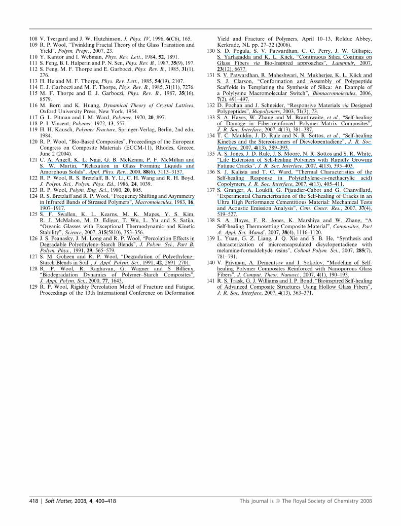
108 V. Tvergard and J. W. Hutchinson, J. Phys. IV, 1996, 6(C6), 165.109 R. P. Wool, ‘‘Twinkling Fractal Theory of the Glass Transition and
Yield’’, Polym. Prepr., 2007, 23.110 Y. Kantor and I. Webman, Phys. Rev. Lett., 1984, 52, 1891.111 S. Feng, B. I. Halperin and P. N. Sen, Phys. Rev. B., 1987, 35(9), 197.112 S. Feng, M. F. Thorpe and E. Garboczi, Phys. Rev. B., 1985, 31(1),
276.113 H. He and M. F. Thorpe, Phys. Rev. Lett., 1985, 54(19), 2107.114 E. J. Garboczi and M. F. Thorpe, Phys. Rev. B., 1985, 31(11), 7276.115 M. F. Thorpe and E. J. Garboczi, Phys. Rev. B., 1987, 35(16),
8579.116 M. Born and K. Huang, Dynamical Theory of Crystal Lattices,
Oxford University Press, New York, 1954.117 G. L. Pitman and I. M. Ward, Polymer, 1970, 20, 897.118 P. I. Vincent, Polymer, 1972, 13, 557.119 H. H. Kausch, Polymer Fracture, Springer-Verlag, Berlin, 2nd edn,
1984.120 R. P. Wool, ‘‘Bio-Based Composites’’, Proceedings of the European
Congress on Composite Materials (ECCM-11), Rhodes, Greece,June 2 (2004).
121 C. A. Angell, K. L. Ngai, G. B. McKenna, P. F. McMillan andS. W. Martin, ‘‘Relaxation in Glass Forming Liquids andAmorphous Solids’’, Appl. Phys. Rev., 2000, 88(6), 3113–3157.
122 R. P. Wool, R. S. Bretzlaff, B. Y. Li, C. H. Wang and R. H. Boyd,J. Polym. Sci., Polym. Phys. Ed., 1986, 24, 1039.
123 R. P. Wool, Polym. Eng. Sci., 1980, 20, 805.124 R. S. Bretzlaff and R. P. Wool, ‘‘Frequency Shifting and Asymmetry
in Infrared Bands of Stressed Polymers’’, Macromolecules, 1983, 16,1907–1917.
125 S. F. Swallen, K. L. Kearns, M. K. Mapes, Y. S. Kim,R. J. McMahon, M. D. Ediger, T. Wu, L. Yu and S. Satija,‘‘Organic Glasses with Exceptional Thermodynamic and KineticStability’’, Science, 2007, 315(5810), 353–356.
126 J. S. Peanasky, J. M. Long and R. P. Wool, ‘‘Percolation Effects inDegradable Polyethylene–Starch Blends’’, J. Polym. Sci., Part B:Polym. Phys., 1991, 29, 565–579.
127 S. M. Goheen and R. P. Wool, ‘‘Degradation of Polyethylene–Starch Blends in Soil’’, J. Appl. Polym. Sci., 1991, 42, 2691–2701.
128 R. P. Wool, R. Raghavan, G. Wagner and S Billieux,‘‘Biodegradation Dynamics of Polymer–Starch Composites’’,J. Appl. Polym. Sci., 2000, 77, 1643.
129 R. P. Wool, Rigidity Percolation Model of Fracture and Fatigue,Proceedings of the 13th International Conference on Deformation
418 | Soft Matter, 2008, 4, 400–418
Yield and Fracture of Polymers, April 10–13, Rolduc Abbey,Kerkrade, NL pp. 27–32 (2006).
130 S. D. Pogula, S. V. Patwardhan, C. C. Perry, J. W. Gillispie,S. Yarlagadda and K. L. Kiick, ‘‘Continuous Silica Coatings onGlass Fibers via Bio-Inspired approaches’’, Langmuir, 2007,23(12), 6677.
131 S. V. Patwardhan, R. Maheshwari, N. Mukherjee, K. L. Kiick andS. J. Clarson, ‘‘Conformation and Assembly of PolypeptideScaffolds in Templating the Synthesis of Silica: An Example ofa Polylysine Macromolecular Switch’’, Biomacromolecules, 2006,7(2), 491–497.
132 D. Pochan and J. Schneider, ‘‘Responsive Materials via DesignedPolypeptides’’, Biopolymers, 2003, 71(3), 73.
133 S. A. Hayes, W. Zhang and M. Branthwaite, et al., ‘‘Self-healingof Damage in Fiber-reinforced Polymer–Matrix Composites’’,J. R. Soc. Interface, 2007, 4(13), 381–387.
134 T. C. Mauldin, J. D. Rule and N. R. Sottos, et al., ‘‘Self-healingKinetics and the Stereoisomers of Dicyclopentadiene’’, J. R. Soc.Interface, 2007, 4(13), 389–393.
135 A. S. Jones, J. D. Rule, J. S. Moore, N. R. Sottos and S. R. White,‘‘Life Extension of Self-healing Polymers with Rapidly GrowingFatigue Cracks’’, J. R. Soc. Interface, 2007, 4(13), 395–403.
136 S. J. Kalista and T. C. Ward, ‘‘Thermal Characteristics of theSelf-healing Response in Poly(ethylene-co-methacrylic acid)Copolymers, J. R. Soc. Interface, 2007, 4(13), 405–411.
137 S. Granger, A. Loukili, G. Pijaudier-Cabot and G. Chanvillard,‘‘Experimental Characterization of the Self-healing of Cracks in anUltra High Performance Cementitious Material: Mechanical Testsand Acoustic Emission Analysis’’, Cem. Concr. Res., 2007, 37(4),519–527.
138 S. A. Hayes, F. R. Jones, K. Marshiya and W. Zhang, ‘‘ASelf-healing Thermosetting Composite Material’’, Composites, PartA: Appl. Sci. Manuf., 2007, 38(4), 1116–1120.
139 L. Yuan, G. Z. Liang, J. Q. Xie and S. B. He, ‘‘Synthesis andcharacterization of microencapsulated dicyclopentadiene withmelamine-formaldehyde resins’’, Colloid Polym. Sci., 2007, 285(7),781–791.
140 V. Privman, A. Dementsov and I. Sokolov, ‘‘Modeling of Self-healing Polymer Composites Reinforced with Nanoporous GlassFibers’’, J. Comput. Theor. Nanosci., 2007, 4(1), 190–193.
141 R. S. Trask, G. J. Williams and I. P. Bond, ‘‘Bioinspired Self-healingof Advanced Composite Structures Using Hollow Glass Fibers’’,J. R. Soc. Interface, 2007, 4(13), 363–371.
This journal is ª The Royal Society of Chemistry 2008