© Siemens AG 2012. All rights reserved.
Industrial Control Panels for North America
Interactive animation on the subject
© Siemens AG 2012. All rights reserved. Industry Sector
Industrial Control Panels for North America Interactive animation on the subject
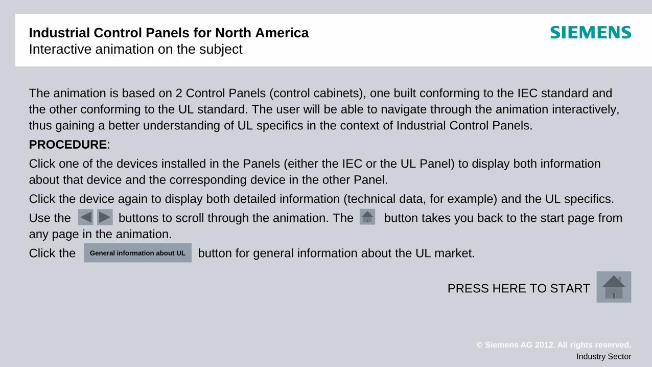
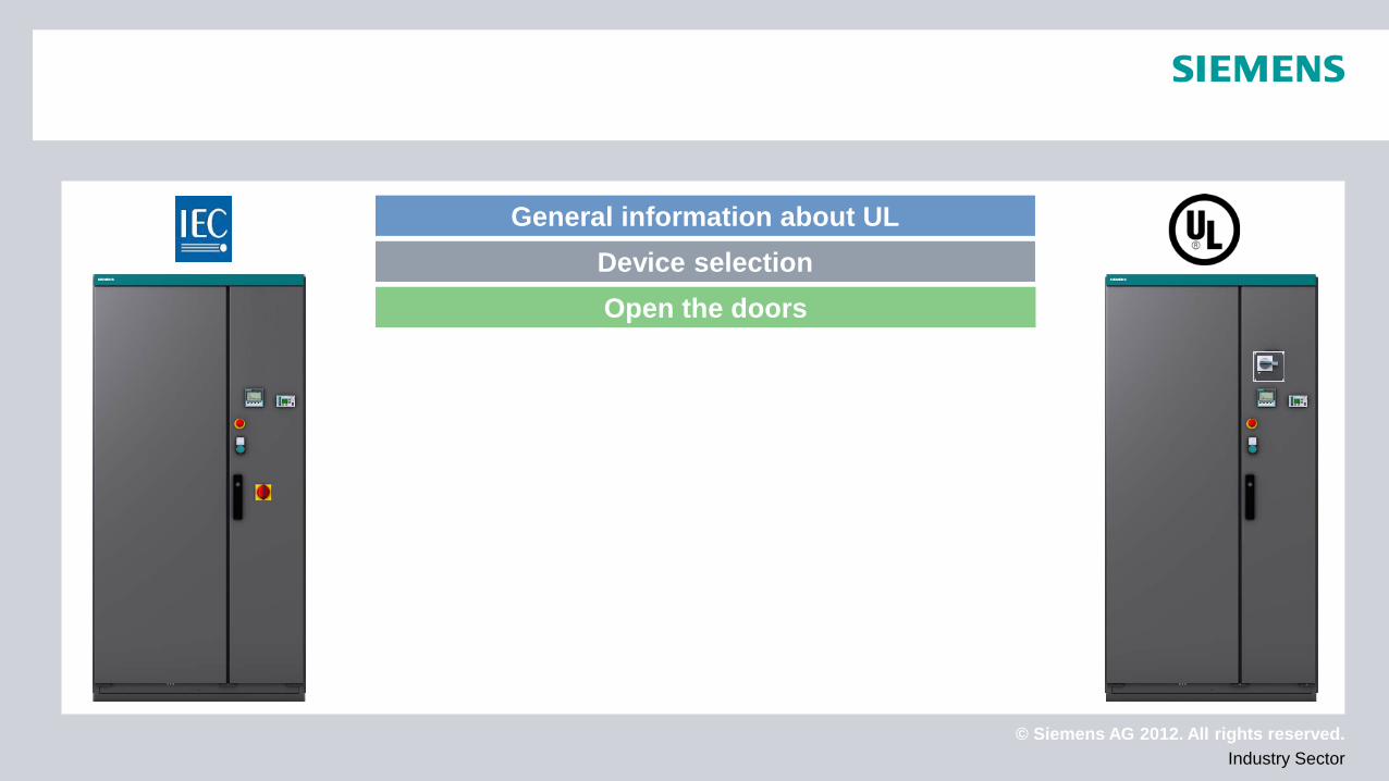
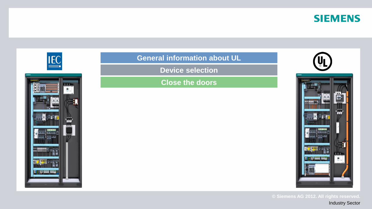
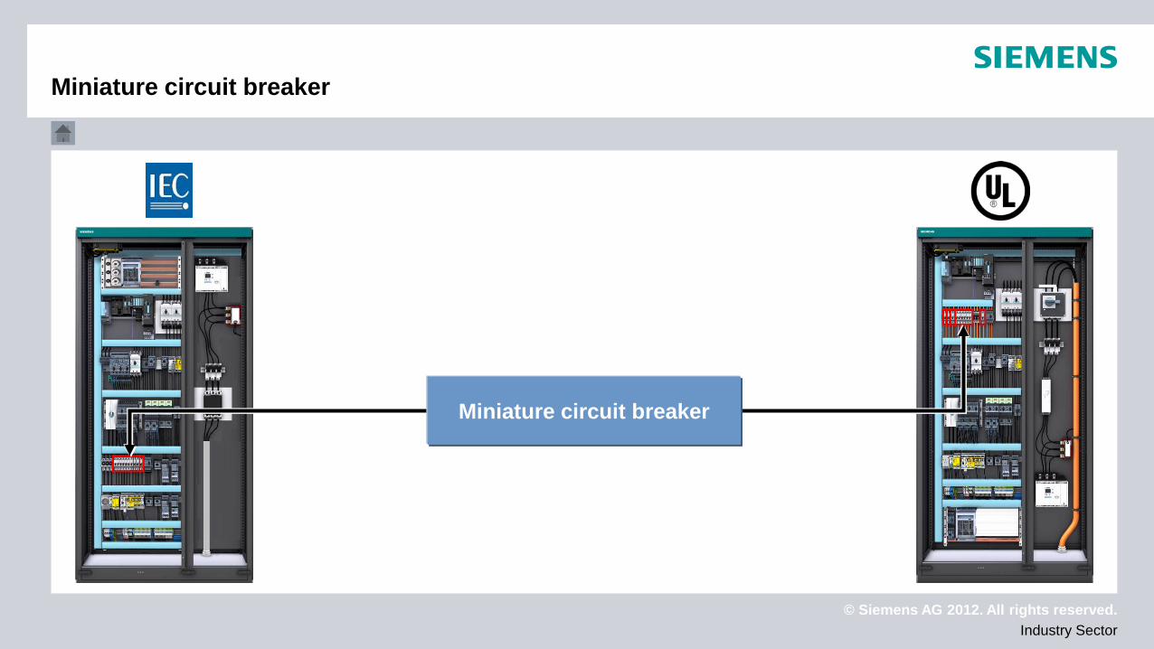
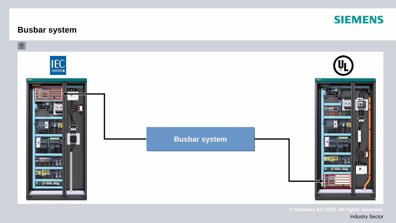
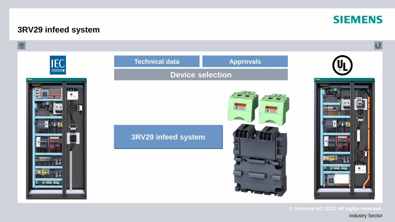
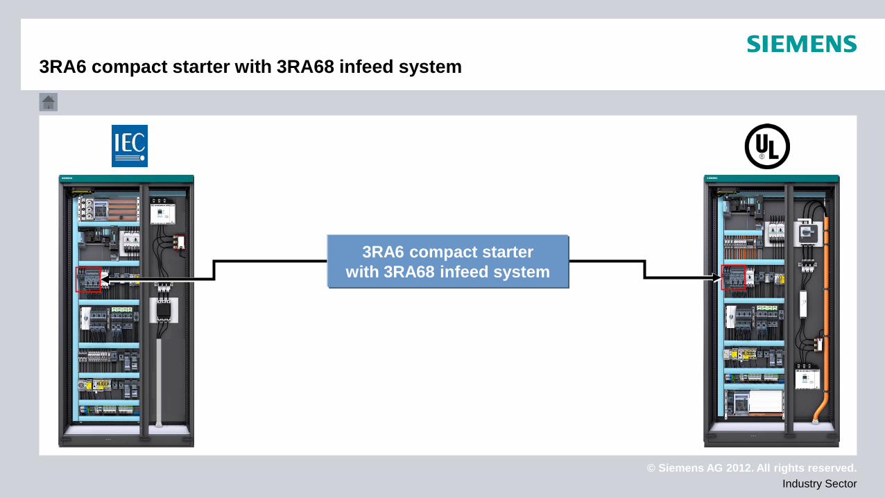
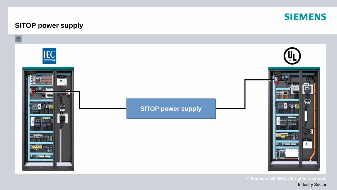
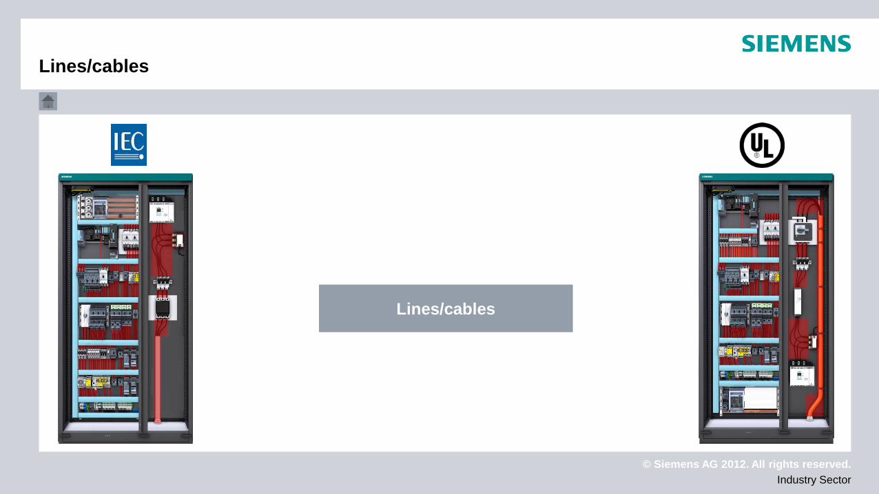
The animation is based on 2 Control Panels (control cabinets), one built conforming to the IEC standard and the other conforming to the UL standard. The user will be able to navigate through the animation interactively, thus gaining a better understanding of UL specifics in the context of Industrial Control Panels. PROCEDURE: Click one of the devices installed in the Panels (either the IEC or the UL Panel) to display both information about that device and the corresponding device in the other Panel. Click the device again to display both detailed information (technical data, for example) and the UL specifics. Use the buttons to scroll through the animation. The button takes you back to the start page from any page in the animation. Click the button for general information about the UL market. PRESS HERE TO START
General information about UL
© Siemens AG 2012. All rights reserved. Industry Sector
General information about UL Device selection Open the doors
© Siemens AG 2012. All rights reserved. Industry Sector
General information about UL Device selection Close the doors
© Siemens AG 2012. All rights reserved. Industry Sector
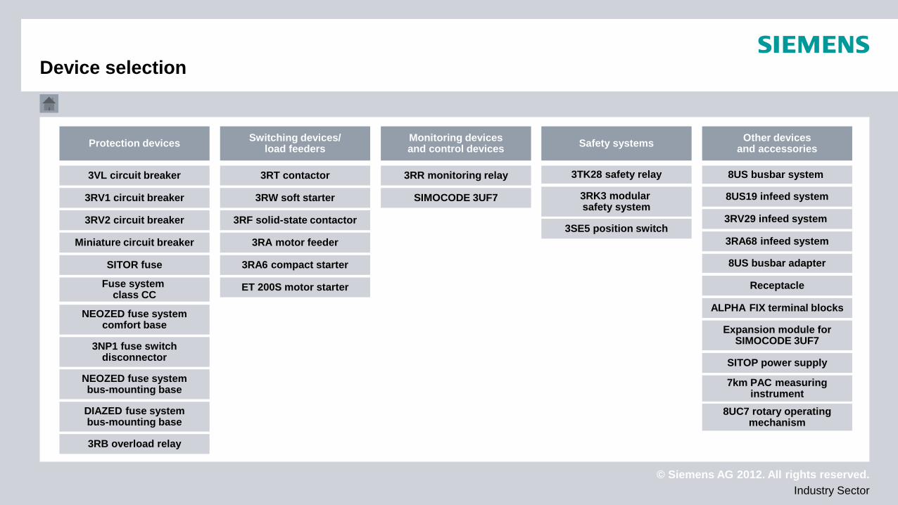
Switching devices/ load feeders Protection devices Other devices
and accessories Safety systems Monitoring devices and control devices
3VL circuit breaker
3RV1 circuit breaker
3RV2 circuit breaker
Miniature circuit breaker
SITOR fuse
NEOZED fuse system comfort base
Fuse system class CC
NEOZED fuse system bus-mounting base
DIAZED fuse system bus-mounting base
3NP1 fuse switch disconnector
3RT contactor
3RW soft starter
3RF solid-state contactor
3RA motor feeder
3RA6 compact starter
3RR monitoring relay
SIMOCODE 3UF7
ET 200S motor starter
3RB overload relay
3TK28 safety relay
3RK3 modular safety system
8US busbar system
8US19 infeed system
3RV29 infeed system
3RA68 infeed system
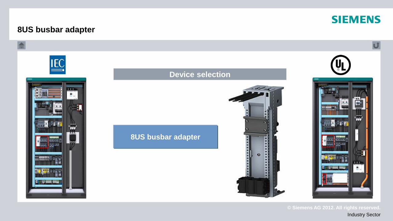
8US busbar adapter
ALPHA FIX terminal blocks
Receptacle
Expansion module for SIMOCODE 3UF7
3SE5 position switch
SITOP power supply
7km PAC measuring instrument
8UC7 rotary operating mechanism
Device selection
© Siemens AG 2012. All rights reserved. Industry Sector
General information about UL
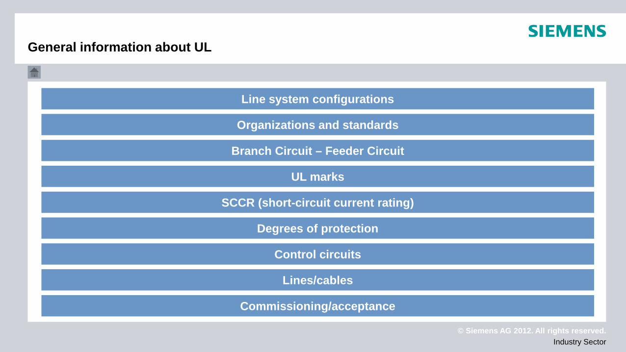
SCCR (short-circuit current rating)
Line system configurations
Organizations and standards
Branch Circuit – Feeder Circuit
UL marks
Degrees of protection
Control circuits
Lines/cables
Commissioning/acceptance
© Siemens AG 2012. All rights reserved. Industry Sector
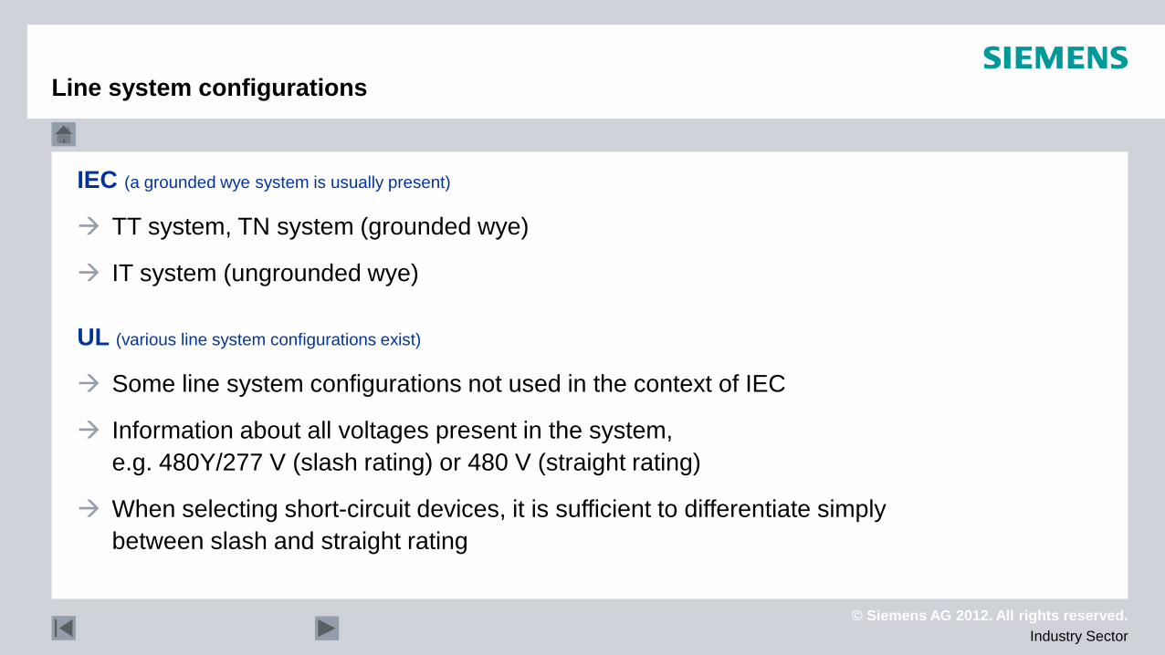
IEC (a grounded wye system is usually present)
TT system, TN system (grounded wye)
IT system (ungrounded wye)
UL (various line system configurations exist)
Some line system configurations not used in the context of IEC
Information about all voltages present in the system, e.g. 480Y/277 V (slash rating) or 480 V (straight rating)
When selecting short-circuit devices, it is sufficient to differentiate simply between slash and straight rating
Line system configurations
© Siemens AG 2012. All rights reserved. Industry Sector
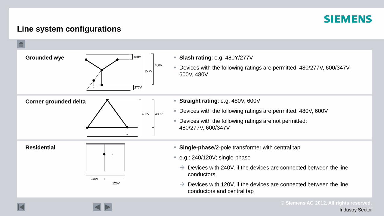
Grounded wye
Corner grounded delta
Residential
Slash rating: e.g. 480Y/277V
Devices with the following ratings are permitted: 480/277V, 600/347V, 600V, 480V
Straight rating: e.g. 480V, 600V
Devices with the following ratings are permitted: 480V, 600V
Devices with the following ratings are not permitted: 480/277V, 600/347V
Single-phase/2-pole transformer with central tap
e.g.: 240/120V; single-phase
Devices with 240V, if the devices are connected between the line conductors
Devices with 120V, if the devices are connected between the line conductors and central tap
277V
277V
480V
480V
480V 480V
240V 120V
Line system configurations
© Siemens AG 2012. All rights reserved. Industry Sector
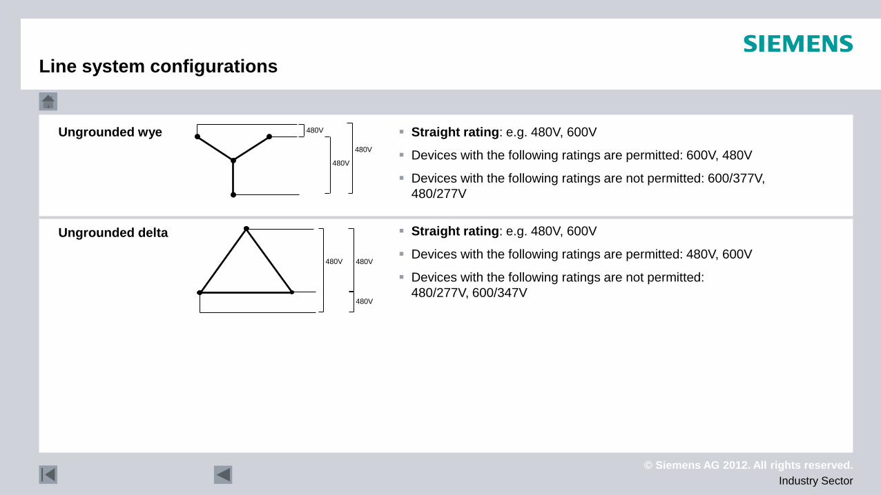
Ungrounded wye
Ungrounded delta
Straight rating: e.g. 480V, 600V
Devices with the following ratings are permitted: 600V, 480V
Devices with the following ratings are not permitted: 600/377V, 480/277V
Straight rating: e.g. 480V, 600V
Devices with the following ratings are permitted: 480V, 600V
Devices with the following ratings are not permitted: 480/277V, 600/347V
480V
480V
480V
480V 480V
480V
Line system configurations
© Siemens AG 2012. All rights reserved. Industry Sector
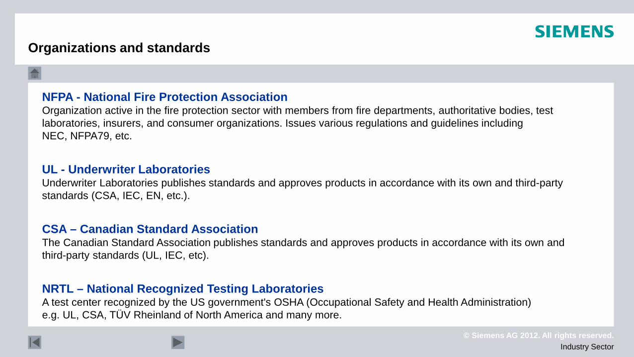
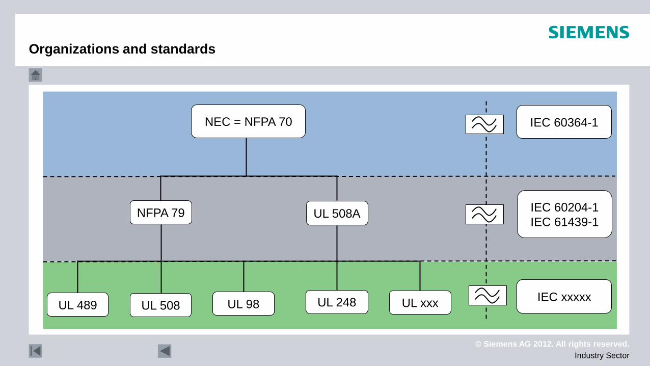
NFPA - National Fire Protection Association Organization active in the fire protection sector with members from fire departments, authoritative bodies, test laboratories, insurers, and consumer organizations. Issues various regulations and guidelines including NEC, NFPA79, etc.
UL - Underwriter Laboratories Underwriter Laboratories publishes standards and approves products in accordance with its own and third-party standards (CSA, IEC, EN, etc.).
CSA – Canadian Standard Association The Canadian Standard Association publishes standards and approves products in accordance with its own and third-party standards (UL, IEC, etc).
NRTL – National Recognized Testing Laboratories A test center recognized by the US government's OSHA (Occupational Safety and Health Administration) e.g. UL, CSA, TÜV Rheinland of North America and many more.
Organizations and standards
© Siemens AG 2012. All rights reserved. Industry Sector
NEC = NFPA 70
NFPA 79 UL 508A
UL xxx UL 248 UL 98 UL 508 UL 489
IEC 60364-1
IEC 60204-1 IEC 61439-1
IEC xxxxx
Organizations and standards
© Siemens AG 2012. All rights reserved. Industry Sector
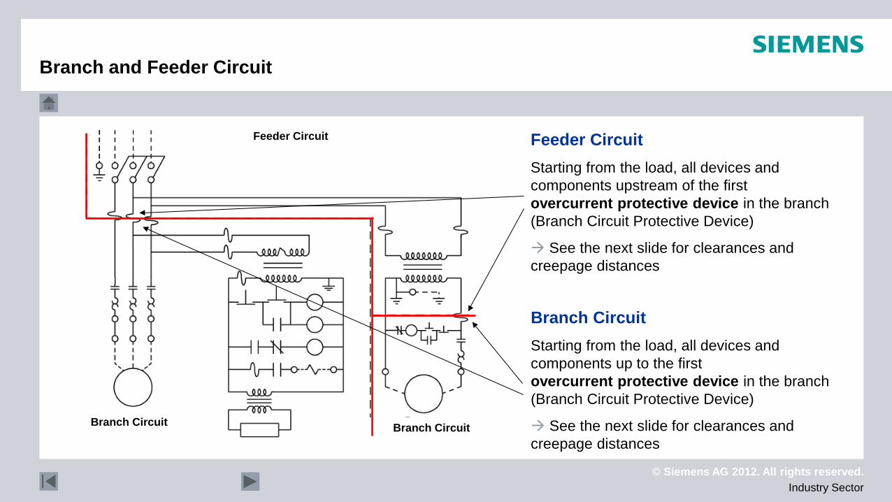
Branch and Feeder Circuit
Feeder Circuit Starting from the load, all devices and components upstream of the first overcurrent protective device in the branch (Branch Circuit Protective Device)
See the next slide for clearances and creepage distances
Branch Circuit Starting from the load, all devices and components up to the first overcurrent protective device in the branch (Branch Circuit Protective Device)
See the next slide for clearances and creepage distances
Feeder Circuit
Branch Circuit
Branch Circuit
© Siemens AG 2012. All rights reserved. Industry Sector
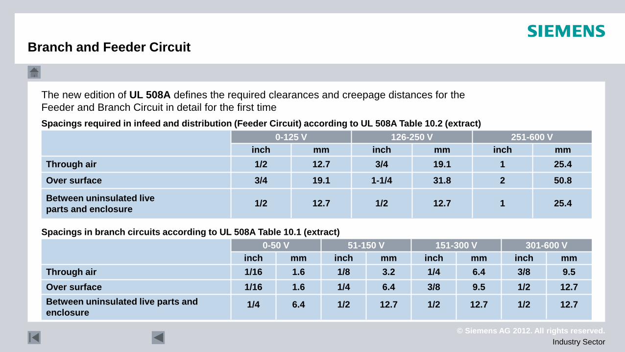
The new edition of UL 508A defines the required clearances and creepage distances for the Feeder and Branch Circuit in detail for the first time
Between uninsulated live parts and enclosure
Over surface
Through air
25.4 1 12.7 1/2 12.7 1/2
50.8 2 31.8 1-1/4 19.1 3/4
25.4 1 19.1 3/4 12.7 1/2 mm mm mm inch inch inch
251-600 V 126-250 V 0-125 V Spacings required in infeed and distribution (Feeder Circuit) according to UL 508A Table 10.2 (extract)
Spacings in branch circuits according to UL 508A Table 10.1 (extract)
Between uninsulated live parts and enclosure
Over surface Through air
12.7
12.7 9.5 mm
12.7
9.5 6.4 mm
12.7
6.4 3.2 mm
6.4
1.6 1.6 mm inch inch inch inch
1/2 1/2 1/2 1/4
1/2 3/8 1/4 1/16 3/8 1/4 1/8 1/16
301-600 V 151-300 V 51-150 V 0-50 V
Branch and Feeder Circuit
© Siemens AG 2012. All rights reserved. Industry Sector
C
US C
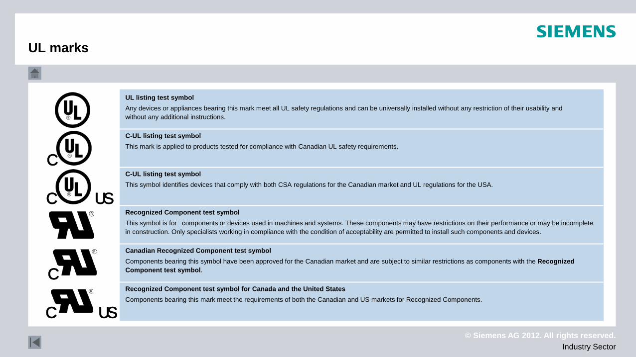
Recognized Component test symbol for Canada and the United States Components bearing this mark meet the requirements of both the Canadian and US markets for Recognized Components.
Canadian Recognized Component test symbol Components bearing this symbol have been approved for the Canadian market and are subject to similar restrictions as components with the Recognized Component test symbol.
Recognized Component test symbol This symbol is for components or devices used in machines and systems. These components may have restrictions on their performance or may be incomplete in construction. Only specialists working in compliance with the condition of acceptability are permitted to install such components and devices.
C-UL listing test symbol This symbol identifies devices that comply with both CSA regulations for the Canadian market and UL regulations for the USA.
C-UL listing test symbol This mark is applied to products tested for compliance with Canadian UL safety requirements.
UL listing test symbol Any devices or appliances bearing this mark meet all UL safety regulations and can be universally installed without any restriction of their usability and without any additional instructions.
C
C US
UL marks
© Siemens AG 2012. All rights reserved. Industry Sector
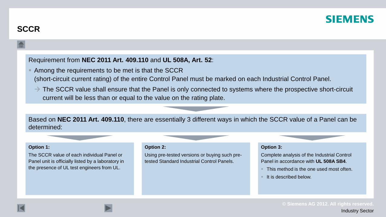
Requirement from NEC 2011 Art. 409.110 and UL 508A, Art. 52: Among the requirements to be met is that the SCCR
(short-circuit current rating) of the entire Control Panel must be marked on each Industrial Control Panel. The SCCR value shall ensure that the Panel is only connected to systems where the prospective short-circuit
current will be less than or equal to the value on the rating plate.
Based on NEC 2011 Art. 409.110, there are essentially 3 different ways in which the SCCR value of a Panel can be determined:
Option 1: The SCCR value of each individual Panel or Panel unit is officially listed by a laboratory in the presence of UL test engineers from UL.
Option 2: Using pre-tested versions or buying such pre-tested Standard Industrial Control Panels.
Option 3: Complete analysis of the Industrial Control Panel in accordance with UL 508A SB4. This method is the one used most often. It is described below.
SCCR
© Siemens AG 2012. All rights reserved. Industry Sector
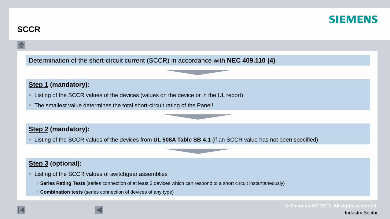
Determination of the short-circuit current (SCCR) in accordance with NEC 409.110 (4)
Step 1 (mandatory): Listing of the SCCR values of the devices (values on the device or in the UL report)
The smallest value determines the total short-circuit rating of the Panel!
Step 2 (mandatory): Listing of the SCCR values of the devices from UL 508A Table SB 4.1 (if an SCCR value has not been specified)
Step 3 (optional): Listing of the SCCR values of switchgear assemblies Series Rating Tests (series connection of at least 2 devices which can respond to a short circuit instantaneously)
Combination tests (series connection of devices of any type)
SCCR
© Siemens AG 2012. All rights reserved. Industry Sector
Type Comparable
IP degree of protection Protection against Installation site (typical application)
UL/NEMA
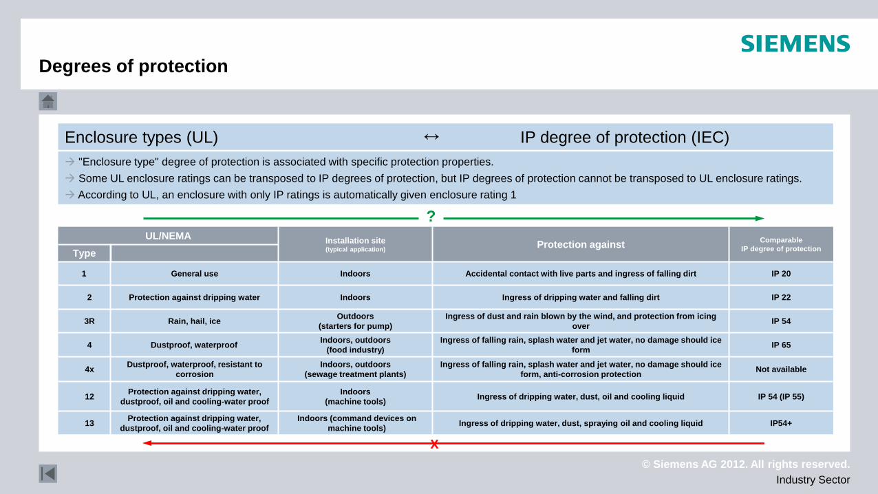
Enclosure types (UL) IP degree of protection (IEC) ↔
?
IP54+ Ingress of dripping water, dust, spraying oil and cooling liquid Indoors (command devices on machine tools)
Protection against dripping water, dustproof, oil and cooling-water proof 13
IP 54 (IP 55) Ingress of dripping water, dust, oil and cooling liquid Indoors (machine tools)
Protection against dripping water, dustproof, oil and cooling-water proof 12
Not available Ingress of falling rain, splash water and jet water, no damage should ice form, anti-corrosion protection
Indoors, outdoors (sewage treatment plants)
Dustproof, waterproof, resistant to corrosion 4x
IP 65 Ingress of falling rain, splash water and jet water, no damage should ice form
Indoors, outdoors (food industry) Dustproof, waterproof 4
IP 54 Ingress of dust and rain blown by the wind, and protection from icing over
Outdoors (starters for pump) Rain, hail, ice 3R
IP 22 Ingress of dripping water and falling dirt Indoors Protection against dripping water 2
IP 20 Accidental contact with live parts and ingress of falling dirt Indoors General use 1
x
"Enclosure type" degree of protection is associated with specific protection properties. Some UL enclosure ratings can be transposed to IP degrees of protection, but IP degrees of protection cannot be transposed to UL enclosure ratings. According to UL, an enclosure with only IP ratings is automatically given enclosure rating 1
Degrees of protection
© Siemens AG 2012. All rights reserved. Industry Sector
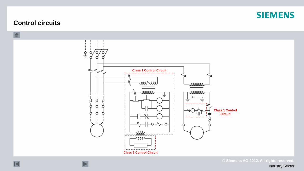
Control circuits
Class 1 Control Circuit
Class 2 Control Circuit
Class 1 Control Circuit
© Siemens AG 2012. All rights reserved. Industry Sector
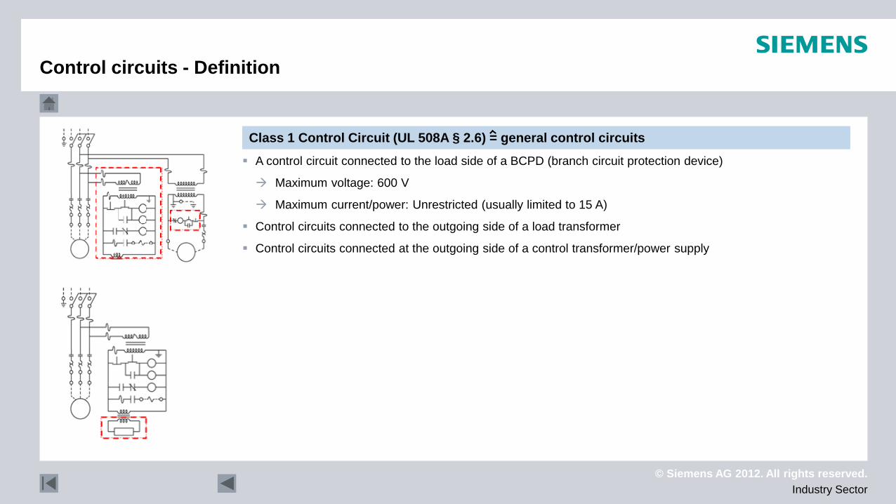
Class 1 Control Circuit (UL 508A § 2.6) = general control circuits A control circuit connected to the load side of a BCPD (branch circuit protection device)
Maximum voltage: 600 V
Maximum current/power: Unrestricted (usually limited to 15 A)
Control circuits connected to the outgoing side of a load transformer
Control circuits connected at the outgoing side of a control transformer/power supply
Control circuits - Definition

© Siemens AG 2012. All rights reserved. Industry Sector
Devices approved "...for use with class 2..." may only be used in these control circuits with limited power
Control circuit supplied with power by an energy source (power supply devices certified acc. to UL1310, UL5085-1 & 3, UL60950-1, UL1950) with max. 30 Vrms
Devices that are used entirely in a "Class 2 circuit" do not have to be checked via the AHJ Unlisted components can be used
Low –Voltage Limited Energy Circuit (UL 508A § 2.32) Control circuit with a "protected" extra-low-voltage
Control circuit with max. 30 Vrms or 42 V peak voltage or DC direct voltage
with a max. power of 100 VA (5 A at 20 V or less)
Devices that are used entirely in a "Limited circuit" do not have to be checked via the AHJ Unlisted components can be used
Control circuits - Definition
Class 2 Control Circuit (UL 508A § 2.7) = control circuits with limited power
© Siemens AG 2012. All rights reserved. Industry Sector
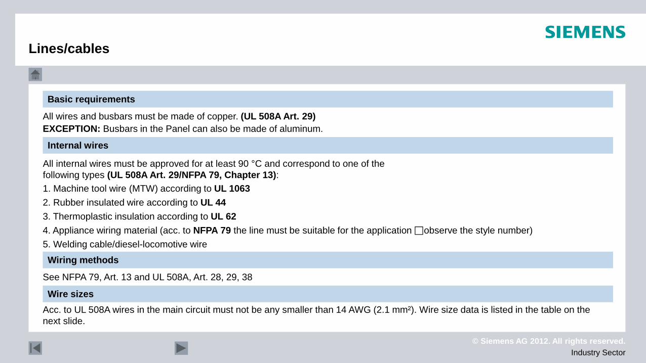
All wires and busbars must be made of copper. (UL 508A Art. 29) EXCEPTION: Busbars in the Panel can also be made of aluminum.
All internal wires must be approved for at least 90 °C and correspond to one of the following types (UL 508A Art. 29/NFPA 79, Chapter 13):
1. Machine tool wire (MTW) according to UL 1063 2. Rubber insulated wire according to UL 44 3. Thermoplastic insulation according to UL 62 4. Appliance wiring material (acc. to NFPA 79 the line must be suitable for the application observe the style number) 5. Welding cable/diesel-locomotive wire
Wiring methods
See NFPA 79, Art. 13 and UL 508A, Art. 28, 29, 38
Basic requirements
Internal wires
Wire sizes Acc. to UL 508A wires in the main circuit must not be any smaller than 14 AWG (2.1 mm²). Wire size data is listed in the table on the next slide.
Lines/cables
© Siemens AG 2012. All rights reserved. Industry Sector
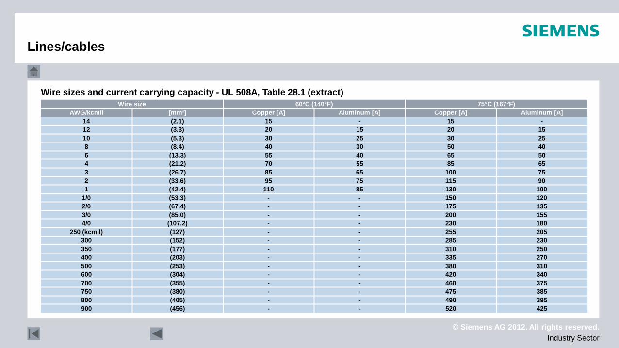
425 520 - - (456) 900 395 490 - - (405) 800 385 475 - - (380) 750 375 460 - - (355) 700 340 420 - - (304) 600 310 380 - - (253) 500 270 335 - - (203) 400 250 310 - - (177) 350 230 285 - - (152) 300 205 255 - - (127) 250 (kcmil) 180 230 - - (107.2) 4/0 155 200 - - (85.0) 3/0 135 175 - - (67.4) 2/0 120 150 - - (53.3) 1/0 100 130 85 110 (42.4) 1 90 115 75 95 (33.6) 2 75 100 65 85 (26.7) 3 65 85 55 70 (21.2) 4 50 65 40 55 (13.3) 6 40 50 30 40 (8.4) 8 25 30 25 30 (5.3) 10 15 20 15 20 (3.3) 12 - 15 - 15 (2.1) 14
Aluminum [A] Copper [A] Aluminum [A] Copper [A] [mm²] AWG/kcmil 75°C (167°F) 60°C (140°F) Wire size
Wire sizes and current carrying capacity - UL 508A, Table 28.1 (extract)
Lines/cables
© Siemens AG 2012. All rights reserved. Industry Sector
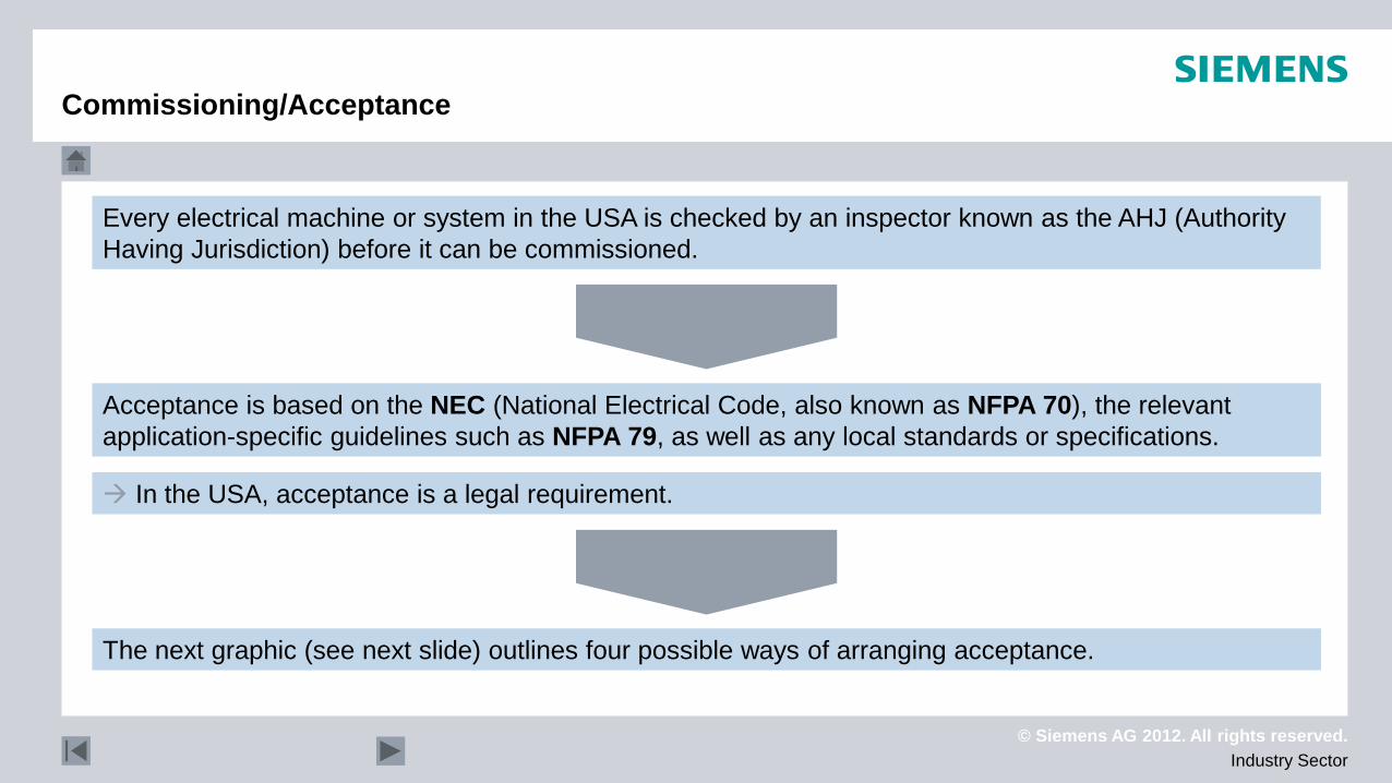
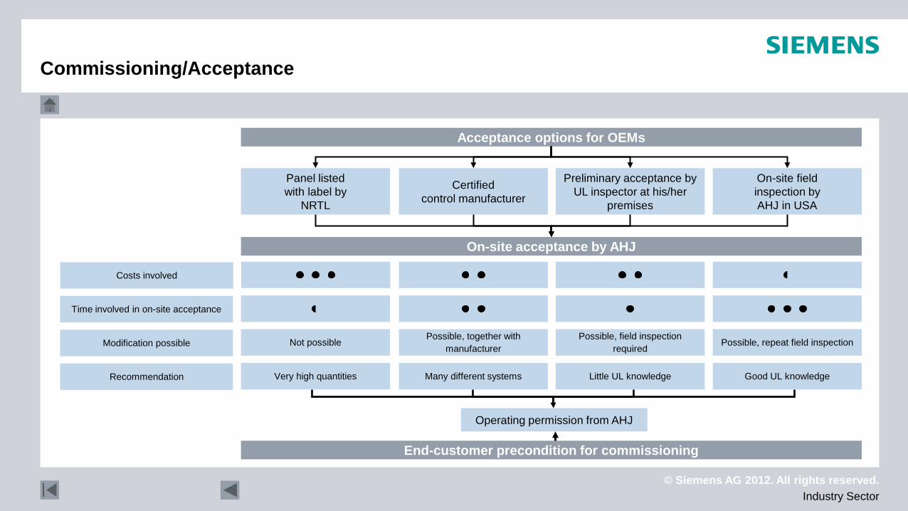
Every electrical machine or system in the USA is checked by an inspector known as the AHJ (Authority Having Jurisdiction) before it can be commissioned.
The next graphic (see next slide) outlines four possible ways of arranging acceptance.
Acceptance is based on the NEC (National Electrical Code, also known as NFPA 70), the relevant application-specific guidelines such as NFPA 79, as well as any local standards or specifications.
In the USA, acceptance is a legal requirement.
Commissioning/Acceptance
© Siemens AG 2012. All rights reserved. Industry Sector
Acceptance options for OEMs
On-site acceptance by AHJ
Good UL knowledge Little UL knowledge Many different systems Very high quantities
Possible, repeat field inspection Possible, field inspection required
Possible, together with manufacturer Not possible
Recommendation
Modification possible
Time involved in on-site acceptance
Costs involved
Operating permission from AHJ
Commissioning/Acceptance
On-site field inspection by AHJ in USA
Preliminary acceptance by UL inspector at his/her
premises
Certified control manufacturer
Panel listed with label by
NRTL
End-customer precondition for commissioning
© Siemens AG 2012. All rights reserved. Industry Sector
Miniature circuit breaker
Miniature circuit breaker
© Siemens AG 2012. All rights reserved. Industry Sector
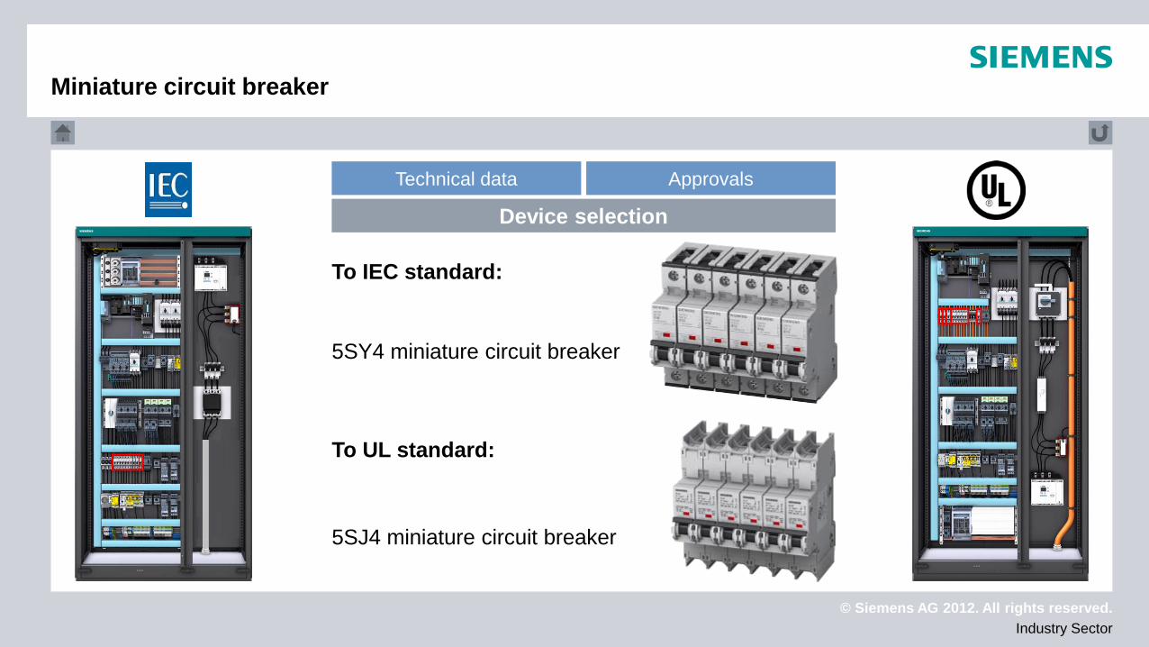
To IEC standard:
To UL standard:
5SJ4 miniature circuit breaker
Technical data Approvals
Device selection
5SY4 miniature circuit breaker
Miniature circuit breaker
© Siemens AG 2012. All rights reserved. Industry Sector
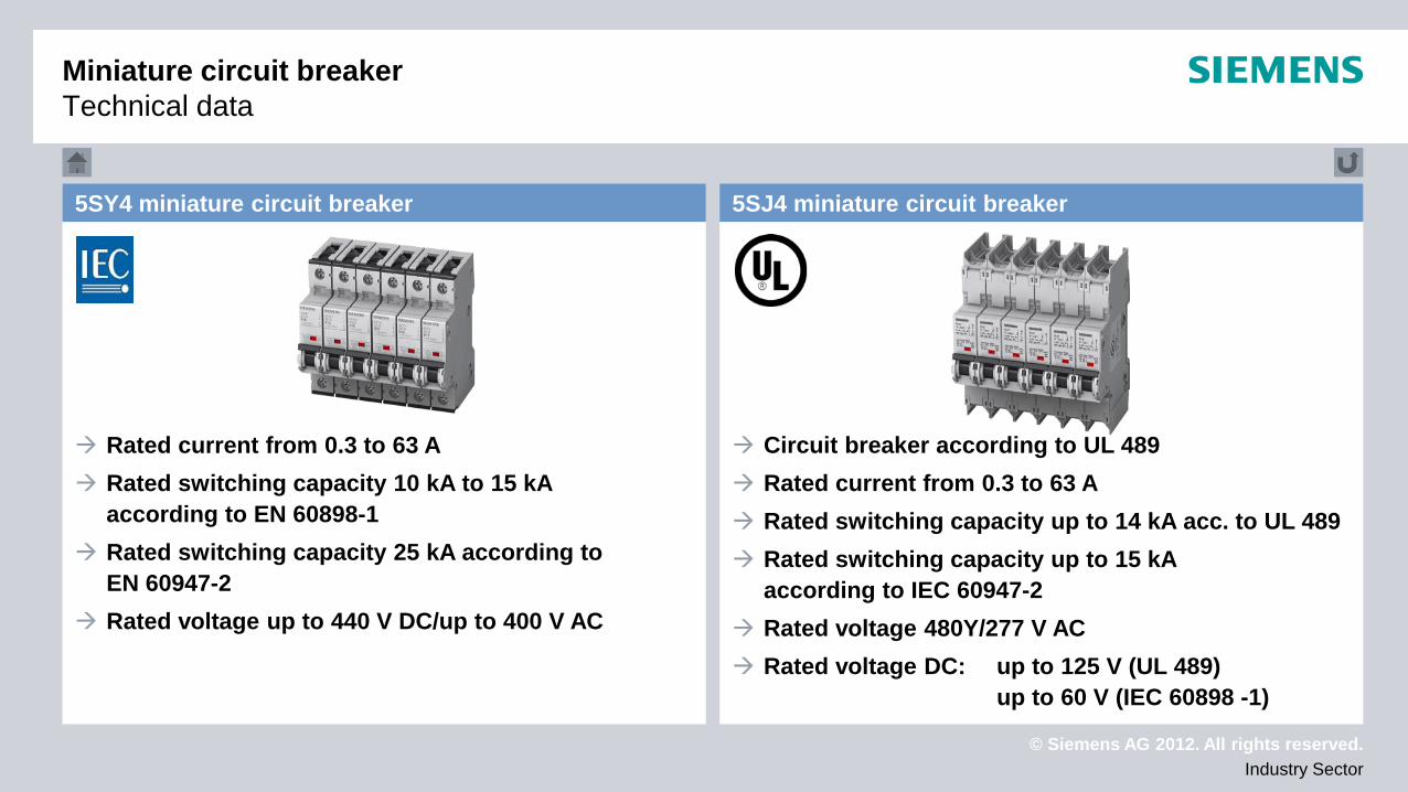
Miniature circuit breaker Technical data
Rated current from 0.3 to 63 A Rated switching capacity 10 kA to 15 kA
according to EN 60898-1 Rated switching capacity 25 kA according to
EN 60947-2 Rated voltage up to 440 V DC/up to 400 V AC
Circuit breaker according to UL 489 Rated current from 0.3 to 63 A Rated switching capacity up to 14 kA acc. to UL 489 Rated switching capacity up to 15 kA
according to IEC 60947-2 Rated voltage 480Y/277 V AC Rated voltage DC: up to 125 V (UL 489)
up to 60 V (IEC 60898 -1)
5SJ4 miniature circuit breaker 5SY4 miniature circuit breaker
© Siemens AG 2012. All rights reserved. Industry Sector
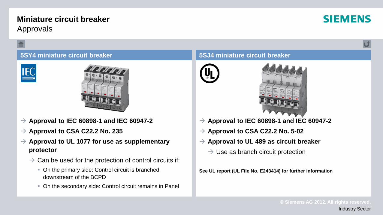
Miniature circuit breaker Approvals
5SJ4 miniature circuit breaker 5SY4 miniature circuit breaker
Approval to IEC 60898-1 and IEC 60947-2 Approval to CSA C22.2 No. 235 Approval to UL 1077 for use as supplementary
protector Can be used for the protection of control circuits if: On the primary side: Control circuit is branched
downstream of the BCPD On the secondary side: Control circuit remains in Panel
Approval to IEC 60898-1 and IEC 60947-2 Approval to CSA C22.2 No. 5-02 Approval to UL 489 as circuit breaker Use as branch circuit protection
See UL report (UL File No. E243414) for further information
© Siemens AG 2012. All rights reserved. Industry Sector
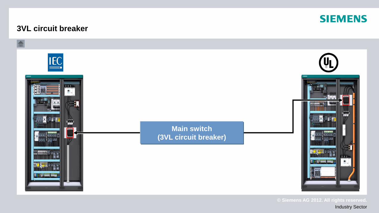
3VL circuit breaker
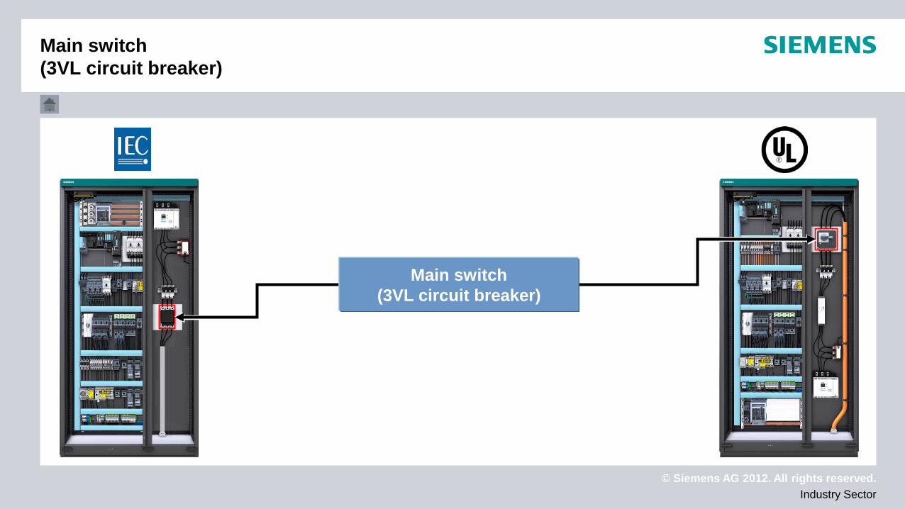
Main switch (3VL circuit breaker)
© Siemens AG 2012. All rights reserved. Industry Sector
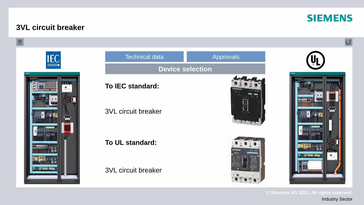
Technical data Approvals
Device selection
3VL circuit breaker
To IEC standard:
To UL standard:
3VL circuit breaker
3VL circuit breaker
© Siemens AG 2012. All rights reserved. Industry Sector
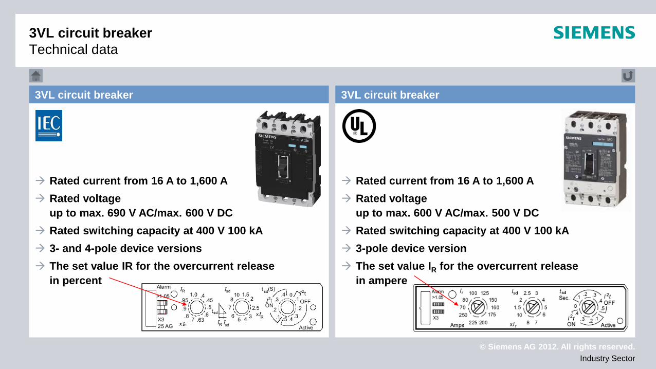
3VL circuit breaker Technical data
Rated current from 16 A to 1,600 A Rated voltage
up to max. 690 V AC/max. 600 V DC Rated switching capacity at 400 V 100 kA 3- and 4-pole device versions The set value IR for the overcurrent release
in percent
Rated current from 16 A to 1,600 A Rated voltage
up to max. 600 V AC/max. 500 V DC Rated switching capacity at 400 V 100 kA 3-pole device version The set value IR for the overcurrent release
in ampere
3VL circuit breaker 3VL circuit breaker
© Siemens AG 2012. All rights reserved. Industry Sector
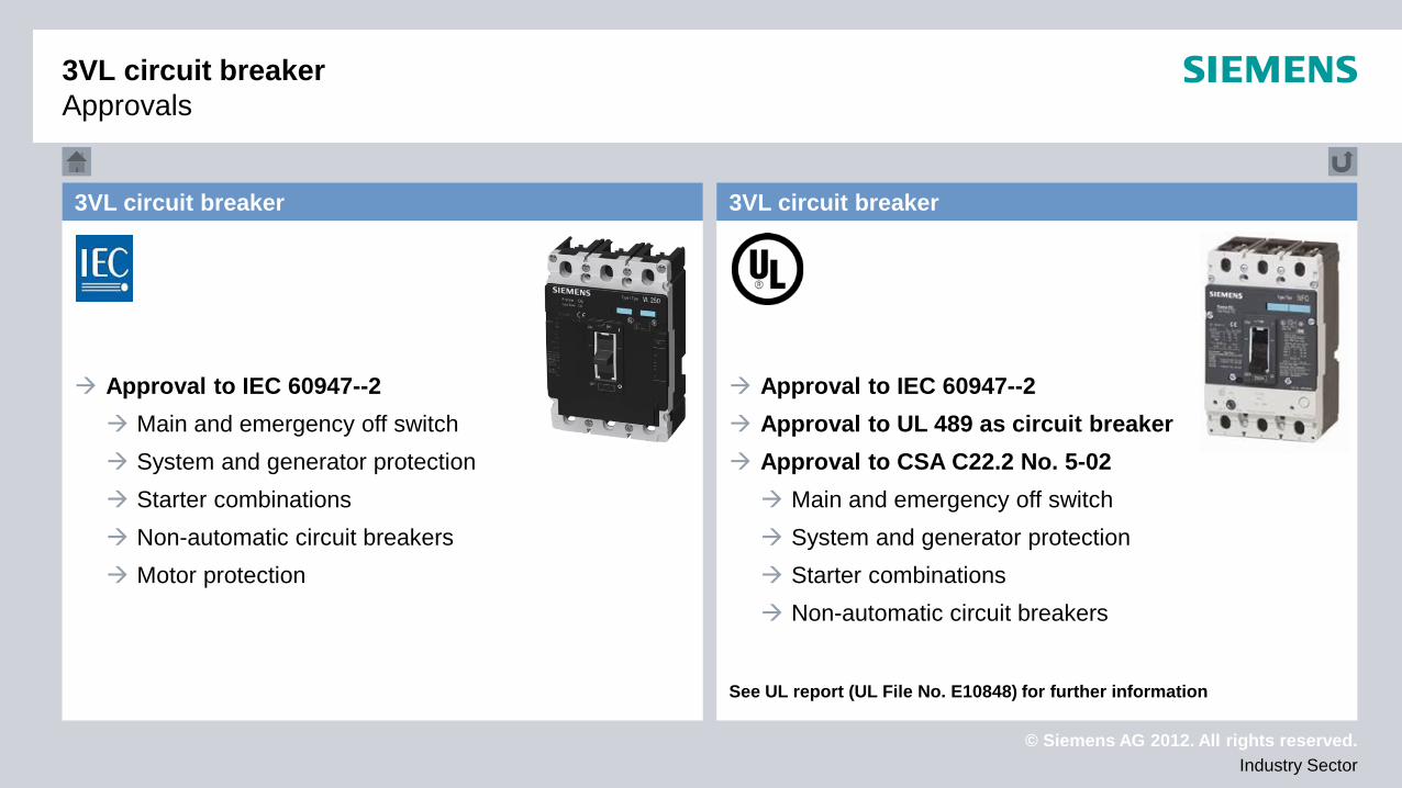
Approval to IEC 60947--2 Main and emergency off switch System and generator protection Starter combinations Non-automatic circuit breakers Motor protection
Approval to IEC 60947--2 Approval to UL 489 as circuit breaker Approval to CSA C22.2 No. 5-02 Main and emergency off switch System and generator protection Starter combinations Non-automatic circuit breakers
See UL report (UL File No. E10848) for further information
3VL circuit breaker 3VL circuit breaker
3VL circuit breaker Approvals
© Siemens AG 2012. All rights reserved. Industry Sector
3RV2 circuit breaker
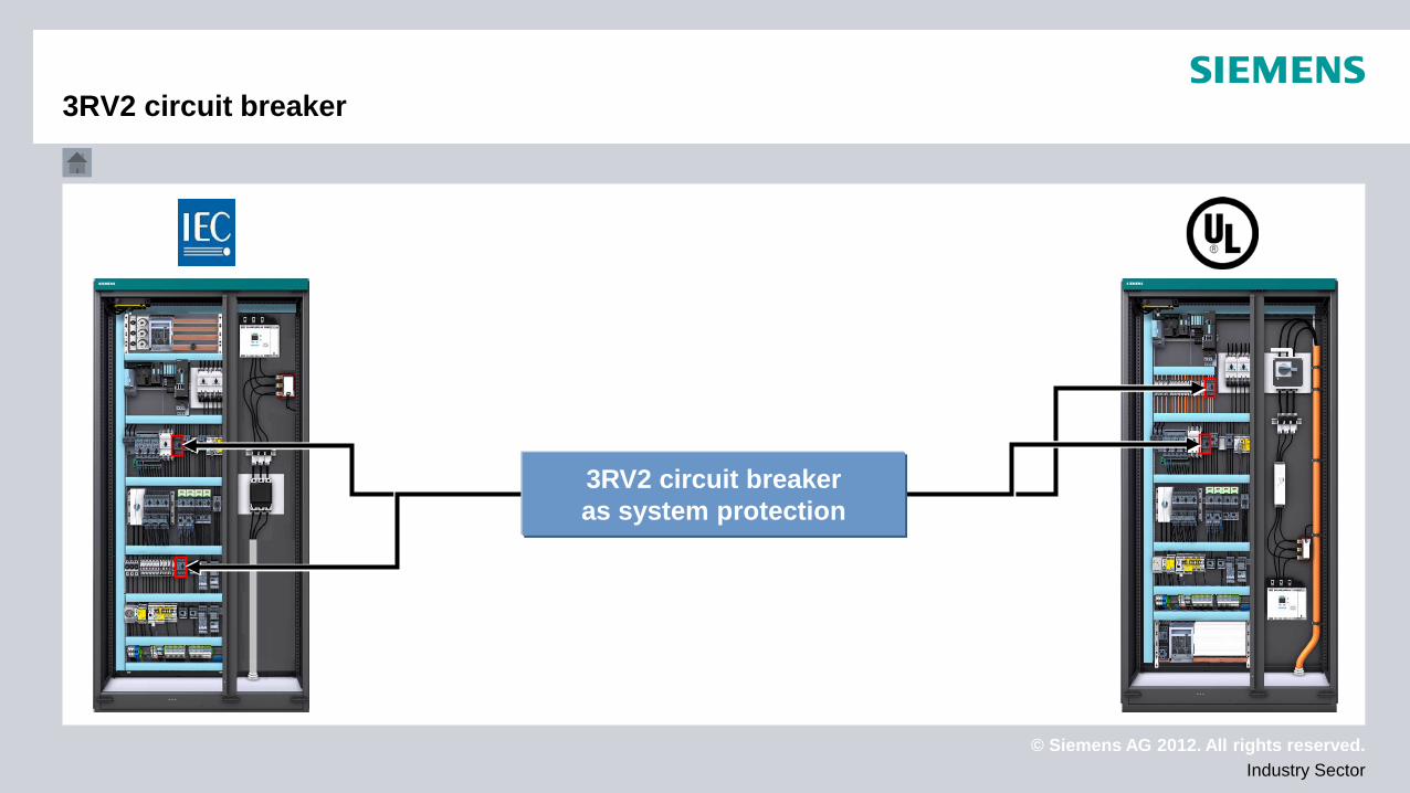
3RV2 circuit breaker as system protection
© Siemens AG 2012. All rights reserved. Industry Sector
Technical data Approvals
Device selection
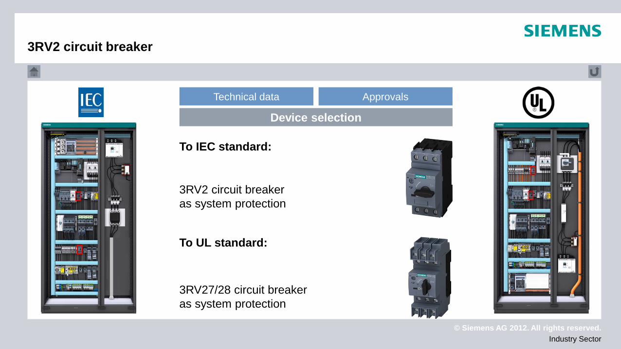
To IEC standard:
To UL standard:
3RV27/28 circuit breaker as system protection
3RV2 circuit breaker as system protection
3RV2 circuit breaker
© Siemens AG 2012. All rights reserved. Industry Sector
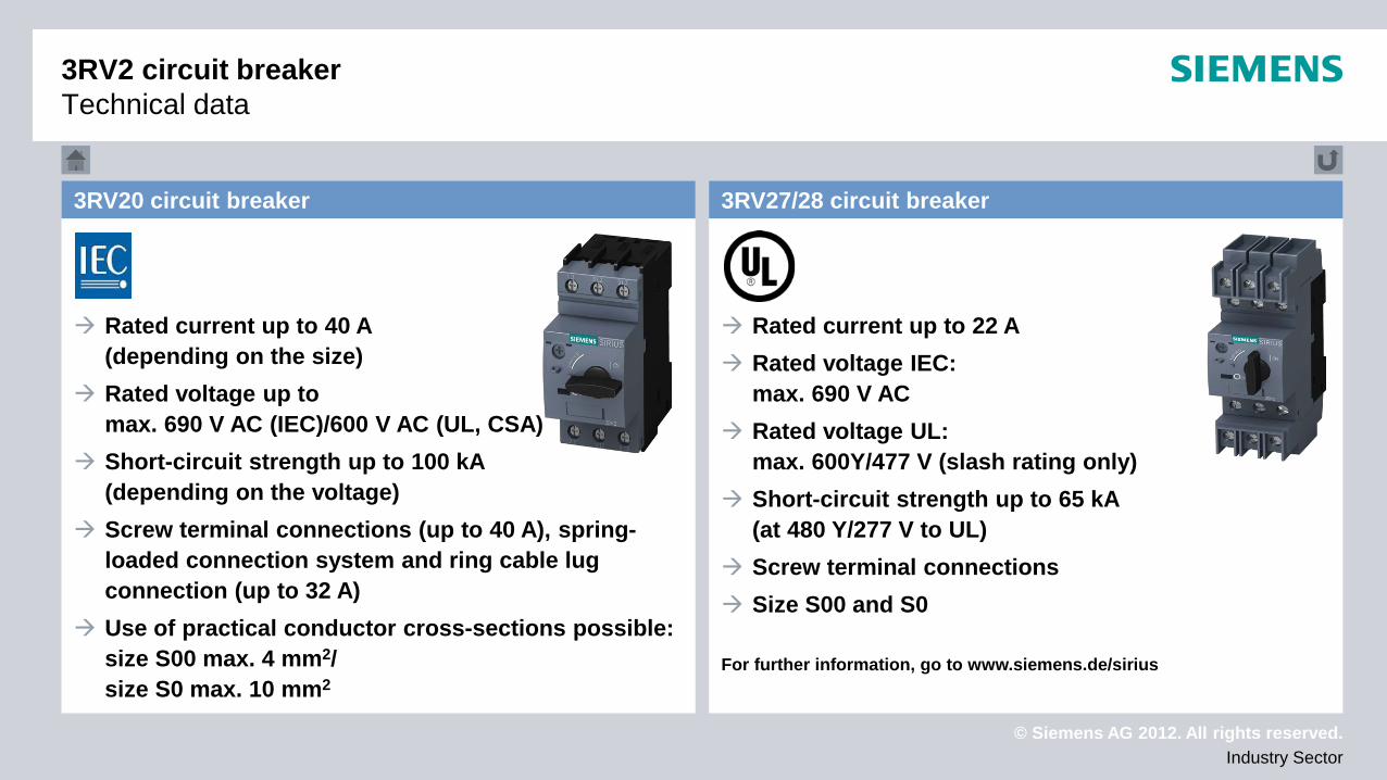
Rated current up to 40 A (depending on the size)
Rated voltage up to max. 690 V AC (IEC)/600 V AC (UL, CSA)
Short-circuit strength up to 100 kA (depending on the voltage)
Screw terminal connections (up to 40 A), spring-loaded connection system and ring cable lug connection (up to 32 A)
Use of practical conductor cross-sections possible: size S00 max. 4 mm2/ size S0 max. 10 mm2
Rated current up to 22 A Rated voltage IEC:
max. 690 V AC Rated voltage UL:
max. 600Y/477 V (slash rating only) Short-circuit strength up to 65 kA
(at 480 Y/277 V to UL) Screw terminal connections Size S00 and S0 For further information, go to www.siemens.de/sirius
3RV27/28 circuit breaker 3RV20 circuit breaker
3RV2 circuit breaker Technical data
© Siemens AG 2012. All rights reserved. Industry Sector
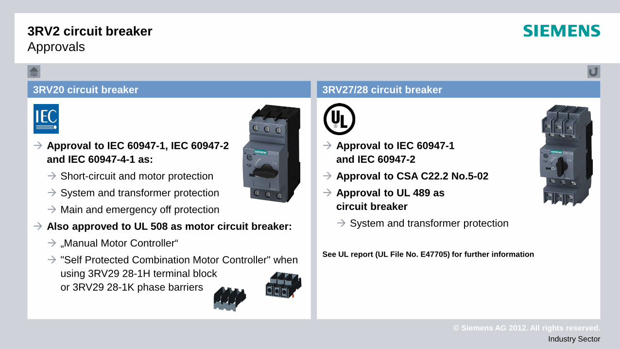
3RV2 circuit breaker Approvals
Approval to IEC 60947-1, IEC 60947-2 and IEC 60947-4-1 as: Short-circuit and motor protection System and transformer protection Main and emergency off protection
Also approved to UL 508 as motor circuit breaker: „Manual Motor Controller“ "Self Protected Combination Motor Controller" when
using 3RV29 28-1H terminal block or 3RV29 28-1K phase barriers
Approval to IEC 60947-1 and IEC 60947-2
Approval to CSA C22.2 No.5-02 Approval to UL 489 as
circuit breaker System and transformer protection
See UL report (UL File No. E47705) for further information
3RV27/28 circuit breaker 3RV20 circuit breaker
© Siemens AG 2012. All rights reserved. Industry Sector
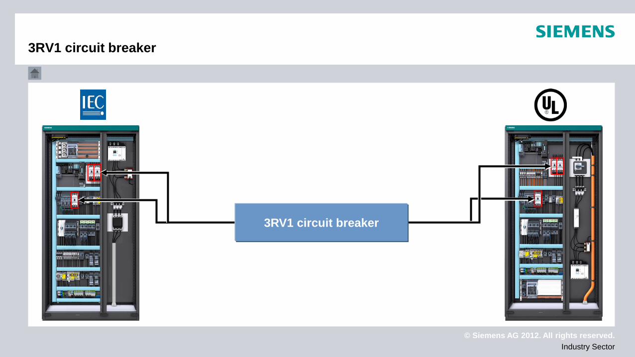
3RV1 circuit breaker
3RV1 circuit breaker
© Siemens AG 2012. All rights reserved. Industry Sector
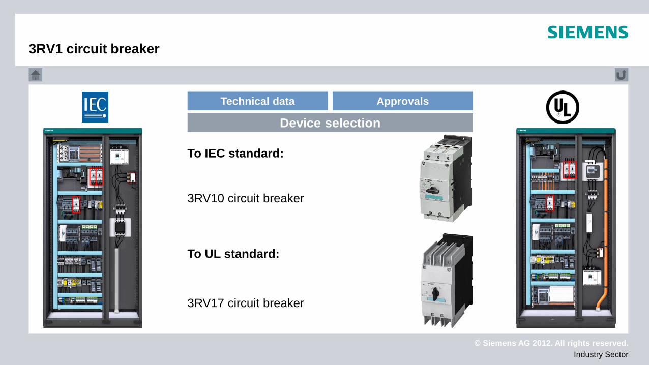
To IEC standard:
To UL standard:
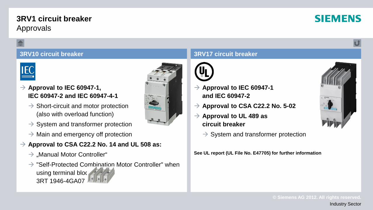
3RV17 circuit breaker
3RV10 circuit breaker
Technical data Approvals
Device selection
3RV1 circuit breaker
© Siemens AG 2012. All rights reserved. Industry Sector
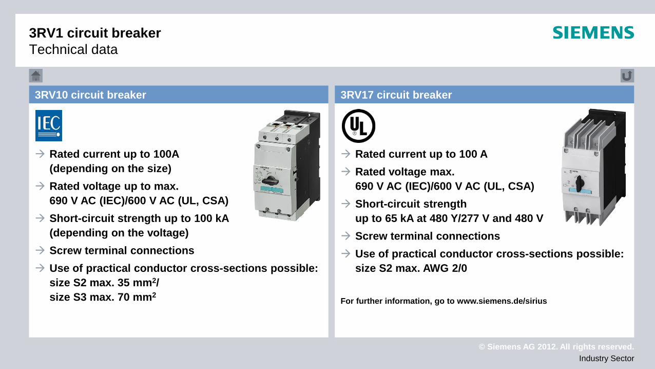
3RV1 circuit breaker Technical data
Rated current up to 100A (depending on the size)
Rated voltage up to max. 690 V AC (IEC)/600 V AC (UL, CSA)
Short-circuit strength up to 100 kA (depending on the voltage)
Screw terminal connections Use of practical conductor cross-sections possible:
size S2 max. 35 mm2/ size S3 max. 70 mm2
Rated current up to 100 A Rated voltage max.
690 V AC (IEC)/600 V AC (UL, CSA) Short-circuit strength
up to 65 kA at 480 Y/277 V and 480 V Screw terminal connections Use of practical conductor cross-sections possible:
size S2 max. AWG 2/0 For further information, go to www.siemens.de/sirius
3RV17 circuit breaker 3RV10 circuit breaker
© Siemens AG 2012. All rights reserved. Industry Sector
Approval to IEC 60947-1, IEC 60947-2 and IEC 60947-4-1 Short-circuit and motor protection
(also with overload function) System and transformer protection Main and emergency off protection
Approval to CSA C22.2 No. 14 and UL 508 as: „Manual Motor Controller“ "Self-Protected Combination Motor Controller" when
using terminal block 3RT 1946-4GA07
Approval to IEC 60947-1 and IEC 60947-2
Approval to CSA C22.2 No. 5-02 Approval to UL 489 as
circuit breaker System and transformer protection
See UL report (UL File No. E47705) for further information
3RV17 circuit breaker 3RV10 circuit breaker
3RV1 circuit breaker Approvals
© Siemens AG 2012. All rights reserved. Industry Sector
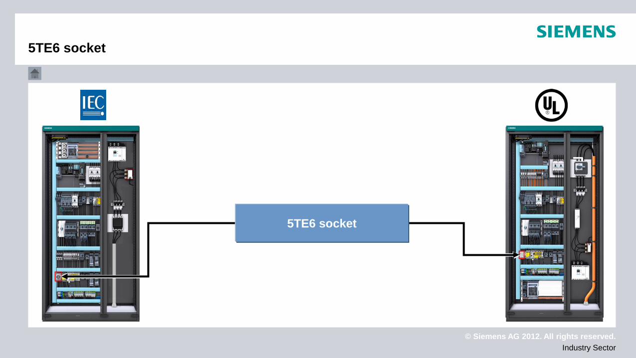
5TE6 socket
5TE6 socket
© Siemens AG 2012. All rights reserved. Industry Sector
Technical data Approvals
Device selection
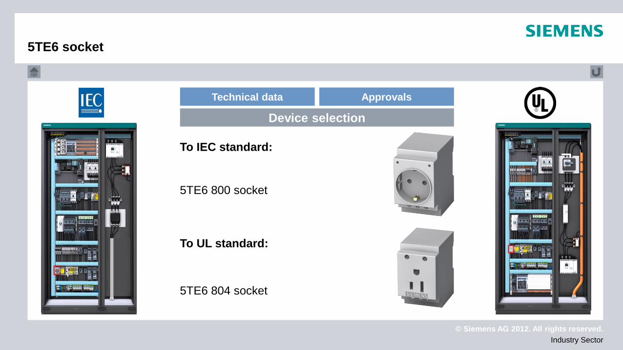
To IEC standard:
To UL standard:
5TE6 804 socket
5TE6 800 socket
5TE6 socket
© Siemens AG 2012. All rights reserved. Industry Sector
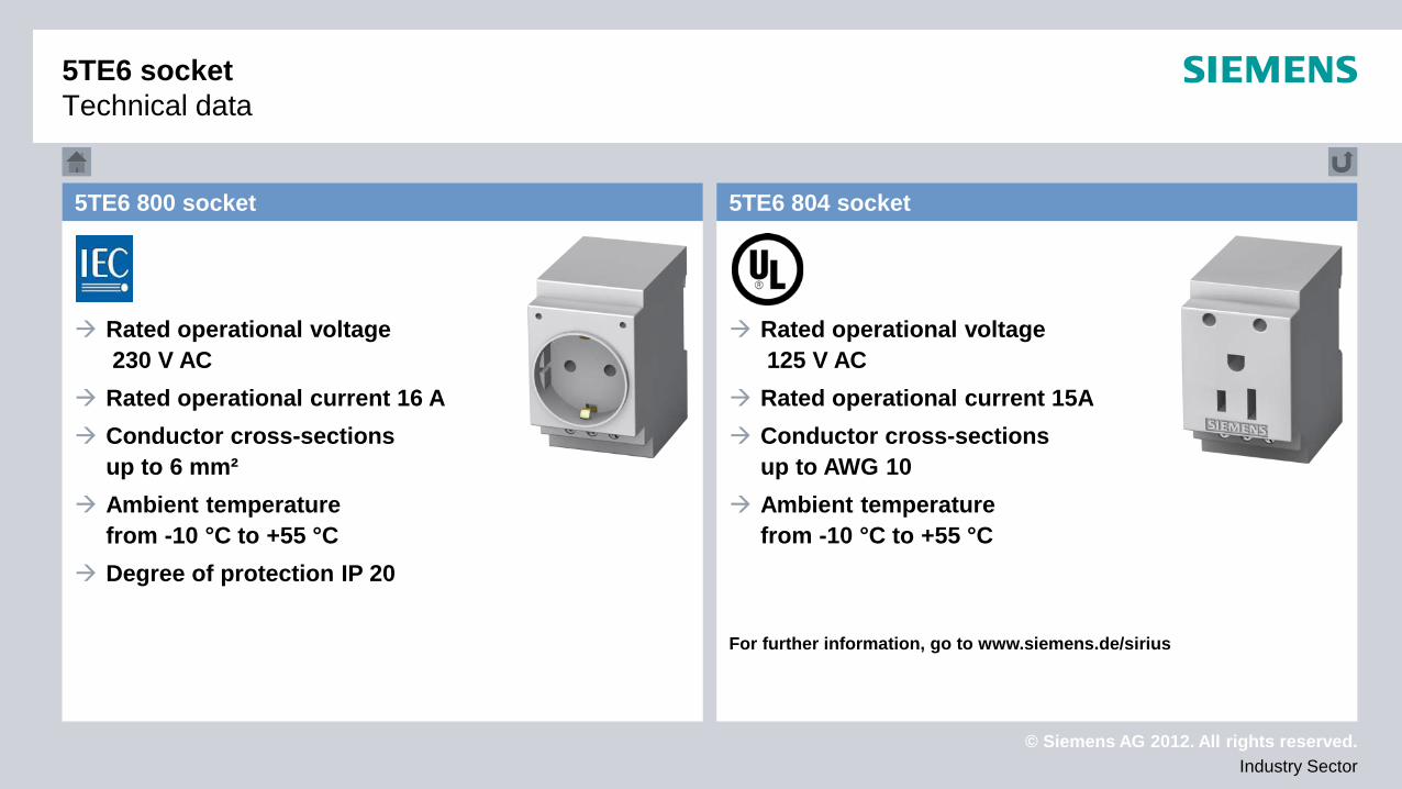
Rated operational voltage 230 V AC
Rated operational current 16 A Conductor cross-sections
up to 6 mm² Ambient temperature
from -10 °C to +55 °C Degree of protection IP 20
Rated operational voltage 125 V AC
Rated operational current 15A Conductor cross-sections
up to AWG 10 Ambient temperature
from -10 °C to +55 °C
For further information, go to www.siemens.de/sirius
5TE6 804 socket 5TE6 800 socket
5TE6 socket Technical data

© Siemens AG 2012. All rights reserved. Industry Sector
Approval to IEC 60204-1 Suitable for mounting in
distribution boards acc. to DIN 43880 Suitable for installation on
DIN rails in switchboards and distribution boards acc. to DIN 60715 Connection of plug-and-play communication devices
in switchboards
Approval to UL 498 Approval to
CSA C22.2 No.182.3M Connection of plug-and-play
communication devices in switchboards
See UL report (UL File No. E258598) for further information
5TE6 804 socket 5TE6 800 socket
5TE6 socket Approvals
© Siemens AG 2012. All rights reserved. Industry Sector
Busbar system
Busbar system
© Siemens AG 2012. All rights reserved. Industry Sector
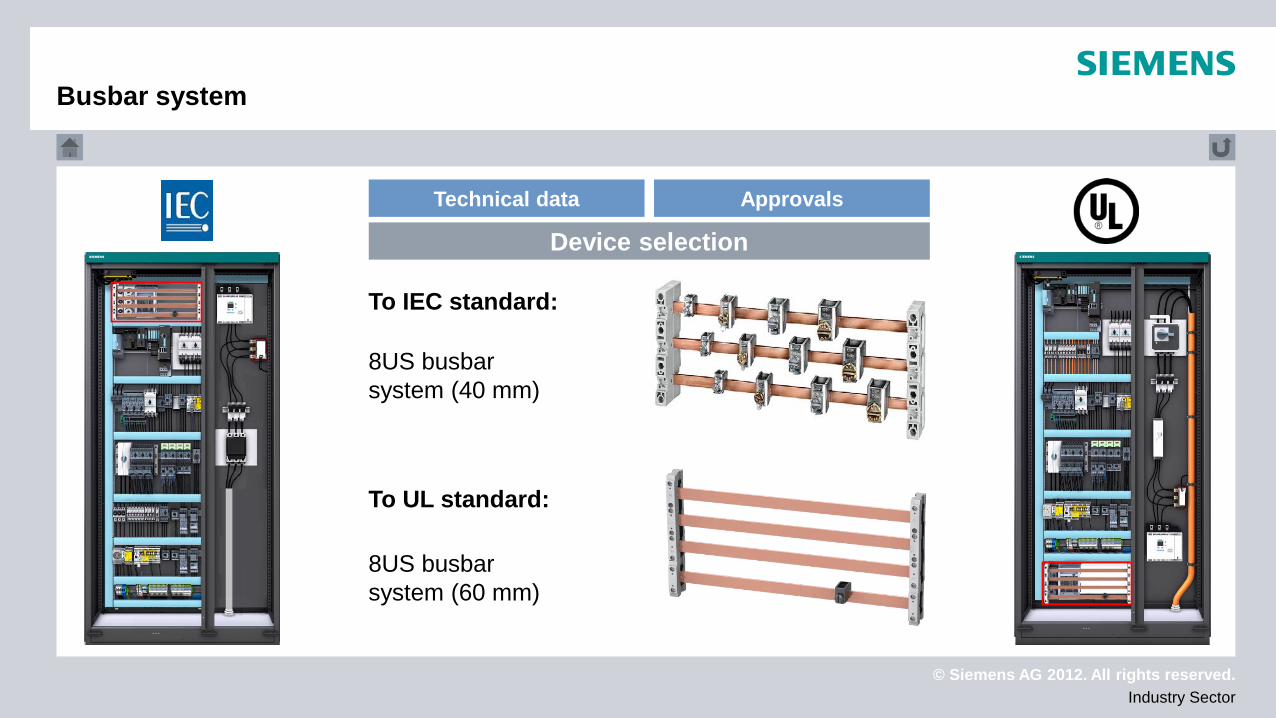
To IEC standard:
To UL standard:
8US busbar system (60 mm)
8US busbar system (40 mm)
Technical data Approvals
Device selection
Busbar system
© Siemens AG 2012. All rights reserved. Industry Sector
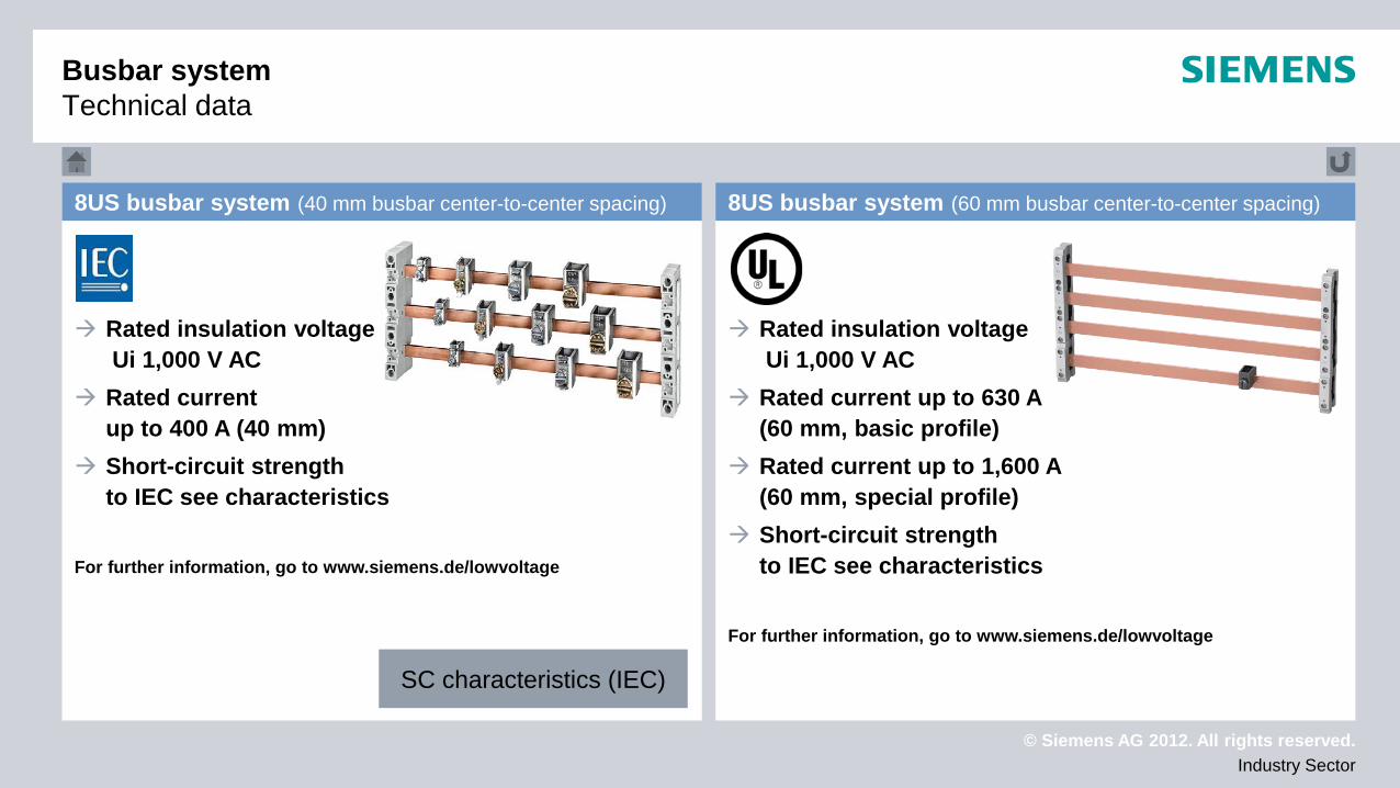
Rated insulation voltage Ui 1,000 V AC
Rated current up to 400 A (40 mm)
Short-circuit strength to IEC see characteristics
For further information, go to www.siemens.de/lowvoltage
Rated insulation voltage Ui 1,000 V AC
Rated current up to 630 A (60 mm, basic profile)
Rated current up to 1,600 A (60 mm, special profile)
Short-circuit strength to IEC see characteristics
For further information, go to www.siemens.de/lowvoltage
8US busbar system (40 mm busbar center-to-center spacing) 8US busbar system (60 mm busbar center-to-center spacing)
SC characteristics (IEC)
Busbar system Technical data
© Siemens AG 2012. All rights reserved. Industry Sector
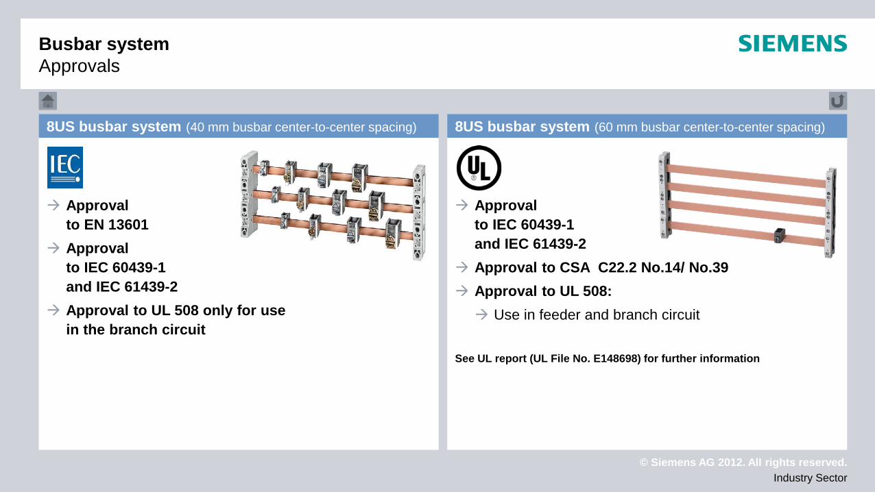
Approval to EN 13601
Approval to IEC 60439-1 and IEC 61439-2
Approval to UL 508 only for use in the branch circuit
Approval to IEC 60439-1 and IEC 61439-2
Approval to CSA C22.2 No.14/ No.39 Approval to UL 508: Use in feeder and branch circuit
See UL report (UL File No. E148698) for further information
8US busbar system (40 mm busbar center-to-center spacing) 8US busbar system (60 mm busbar center-to-center spacing)
Busbar system Approvals
© Siemens AG 2012. All rights reserved. Industry Sector
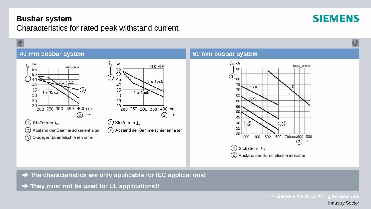
40 mm busbar system 60 mm busbar system
The characteristics are only applicable for IEC applications!
They must not be used for UL applications!!
Busbar system Characteristics for rated peak withstand current
© Siemens AG 2012. All rights reserved. Industry Sector
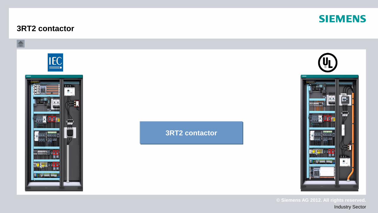
3RT2 contactor
3RT2 contactor
© Siemens AG 2012. All rights reserved. Industry Sector
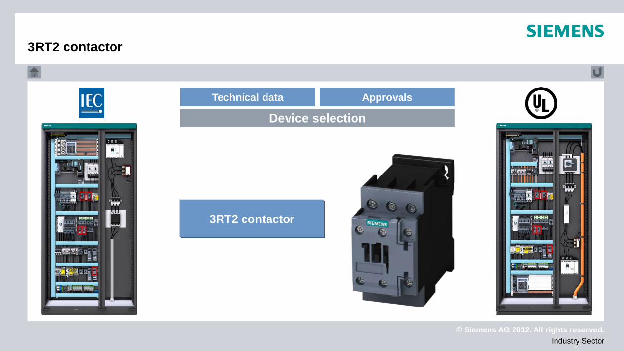
Technical data Approvals
Device selection
3RT2 contactor
3RT2 contactor
© Siemens AG 2012. All rights reserved. Industry Sector
3RT2 contactor
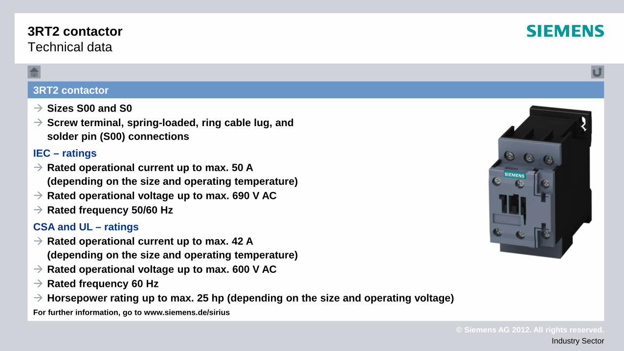
3RT2 contactor Technical data
Sizes S00 and S0 Screw terminal, spring-loaded, ring cable lug, and
solder pin (S00) connections IEC – ratings Rated operational current up to max. 50 A
(depending on the size and operating temperature) Rated operational voltage up to max. 690 V AC Rated frequency 50/60 Hz CSA and UL – ratings Rated operational current up to max. 42 A
(depending on the size and operating temperature) Rated operational voltage up to max. 600 V AC Rated frequency 60 Hz Horsepower rating up to max. 25 hp (depending on the size and operating voltage) For further information, go to www.siemens.de/sirius
© Siemens AG 2012. All rights reserved. Industry Sector
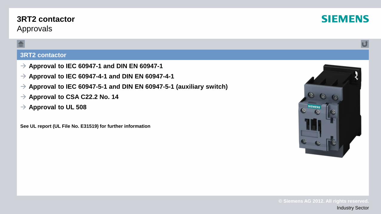
3RT2 contactor Approval to IEC 60947-1 and DIN EN 60947-1 Approval to IEC 60947-4-1 and DIN EN 60947-4-1 Approval to IEC 60947-5-1 and DIN EN 60947-5-1 (auxiliary switch) Approval to CSA C22.2 No. 14 Approval to UL 508
See UL report (UL File No. E31519) for further information
3RT2 contactor Approvals
© Siemens AG 2012. All rights reserved. Industry Sector
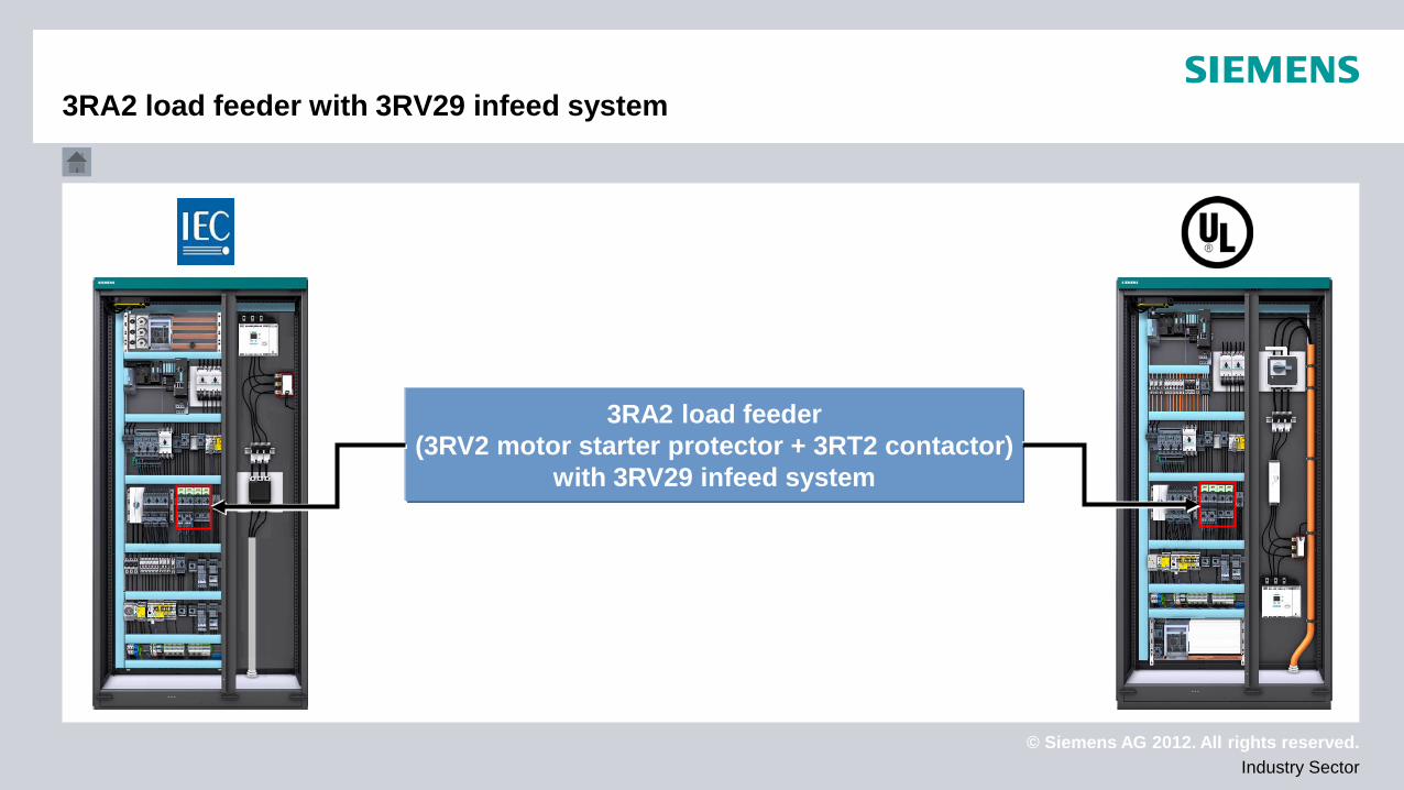
3RA2 load feeder (3RV2 motor starter protector + 3RT2 contactor)
with 3RV29 infeed system
3RA2 load feeder with 3RV29 infeed system
© Siemens AG 2012. All rights reserved. Industry Sector
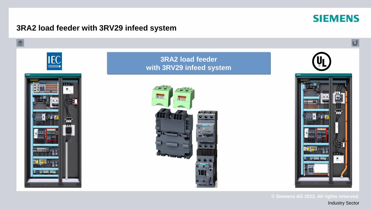
3RA2 load feeder with 3RV29 infeed system
3RA2 load feeder with 3RV29 infeed system
© Siemens AG 2012. All rights reserved. Industry Sector
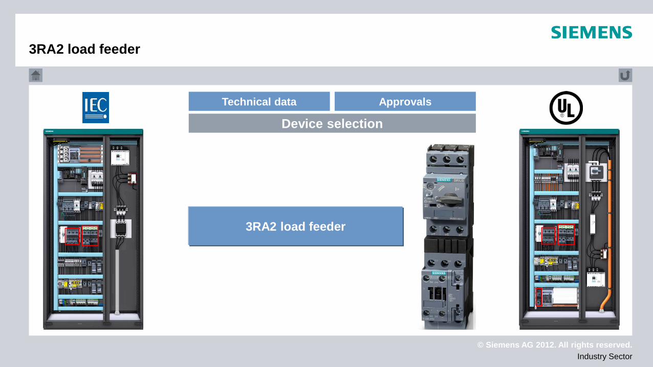
Technical data Approvals
Device selection
3RA2 load feeder
3RA2 load feeder
© Siemens AG 2012. All rights reserved. Industry Sector
3RV29 infeed system
Technical data Approvals
Device selection
3RV29 infeed system
© Siemens AG 2012. All rights reserved. Industry Sector
3RA2 load feeder
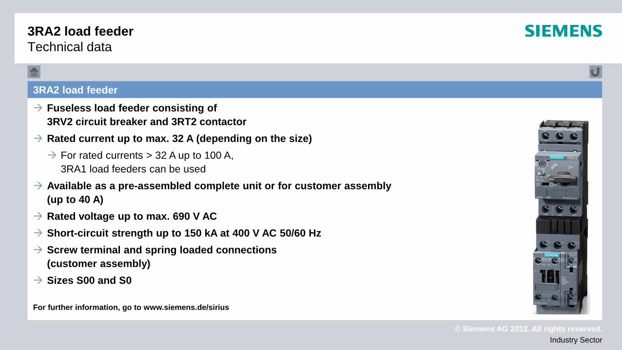
3RA2 load feeder Technical data
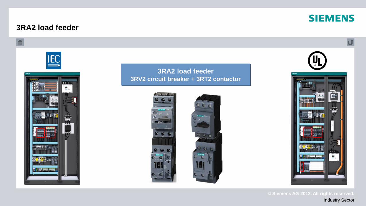
Fuseless load feeder consisting of 3RV2 circuit breaker and 3RT2 contactor
Rated current up to max. 32 A (depending on the size) For rated currents > 32 A up to 100 A,
3RA1 load feeders can be used Available as a pre-assembled complete unit or for customer assembly
(up to 40 A) Rated voltage up to max. 690 V AC Short-circuit strength up to 150 kA at 400 V AC 50/60 Hz Screw terminal and spring loaded connections
(customer assembly) Sizes S00 and S0 For further information, go to www.siemens.de/sirius
© Siemens AG 2012. All rights reserved. Industry Sector
3RA2 load feeder
3RA2 load feeder Approvals
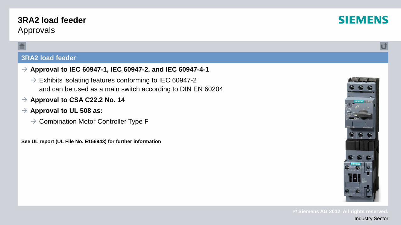
Approval to IEC 60947-1, IEC 60947-2, and IEC 60947-4-1 Exhibits isolating features conforming to IEC 60947-2
and can be used as a main switch according to DIN EN 60204 Approval to CSA C22.2 No. 14 Approval to UL 508 as: Combination Motor Controller Type F
See UL report (UL File No. E156943) for further information
© Siemens AG 2012. All rights reserved. Industry Sector
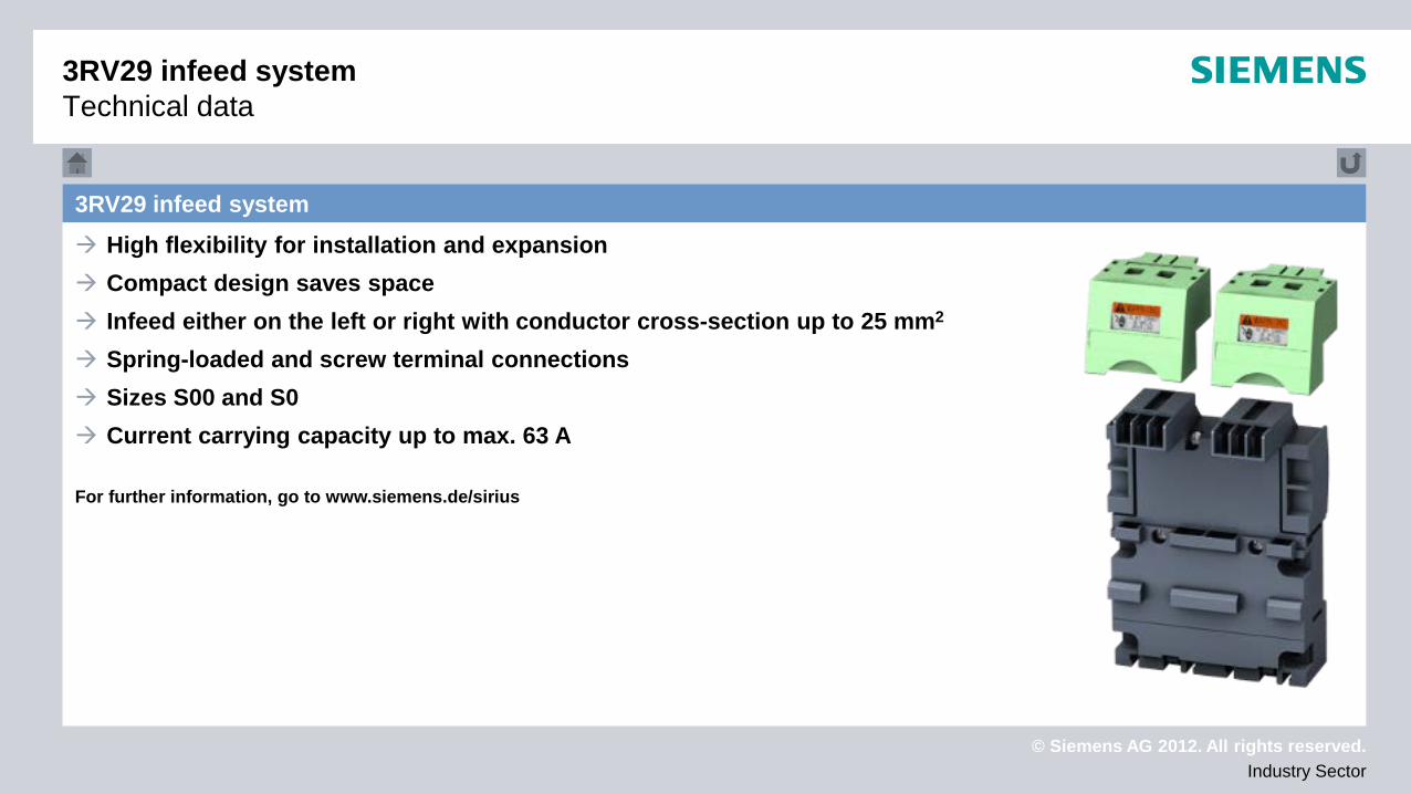
3RV29 infeed system High flexibility for installation and expansion Compact design saves space Infeed either on the left or right with conductor cross-section up to 25 mm2 Spring-loaded and screw terminal connections Sizes S00 and S0 Current carrying capacity up to max. 63 A For further information, go to www.siemens.de/sirius
3RV29 infeed system Technical data
© Siemens AG 2012. All rights reserved. Industry Sector
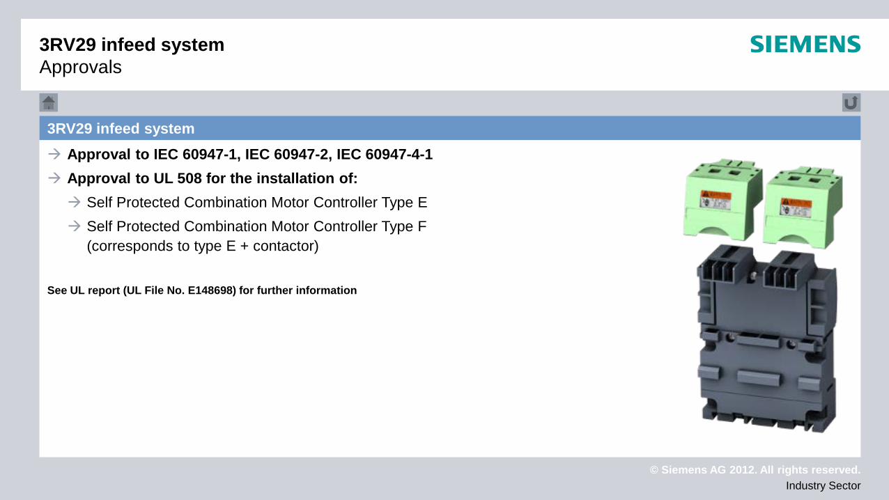
3RV29 infeed system Approval to IEC 60947-1, IEC 60947-2, IEC 60947-4-1 Approval to UL 508 for the installation of: Self Protected Combination Motor Controller Type E Self Protected Combination Motor Controller Type F
(corresponds to type E + contactor) See UL report (UL File No. E148698) for further information
3RV29 infeed system Approvals
© Siemens AG 2012. All rights reserved. Industry Sector
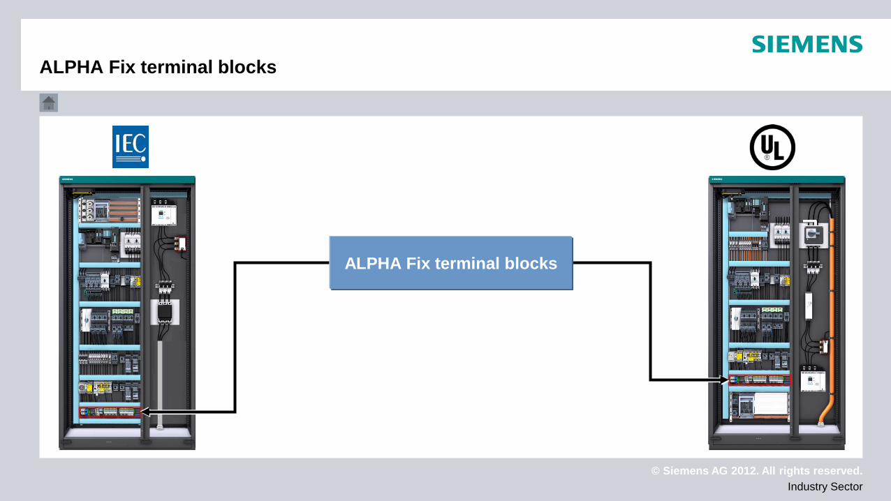
ALPHA Fix terminal blocks
ALPHA Fix terminal blocks
© Siemens AG 2012. All rights reserved. Industry Sector
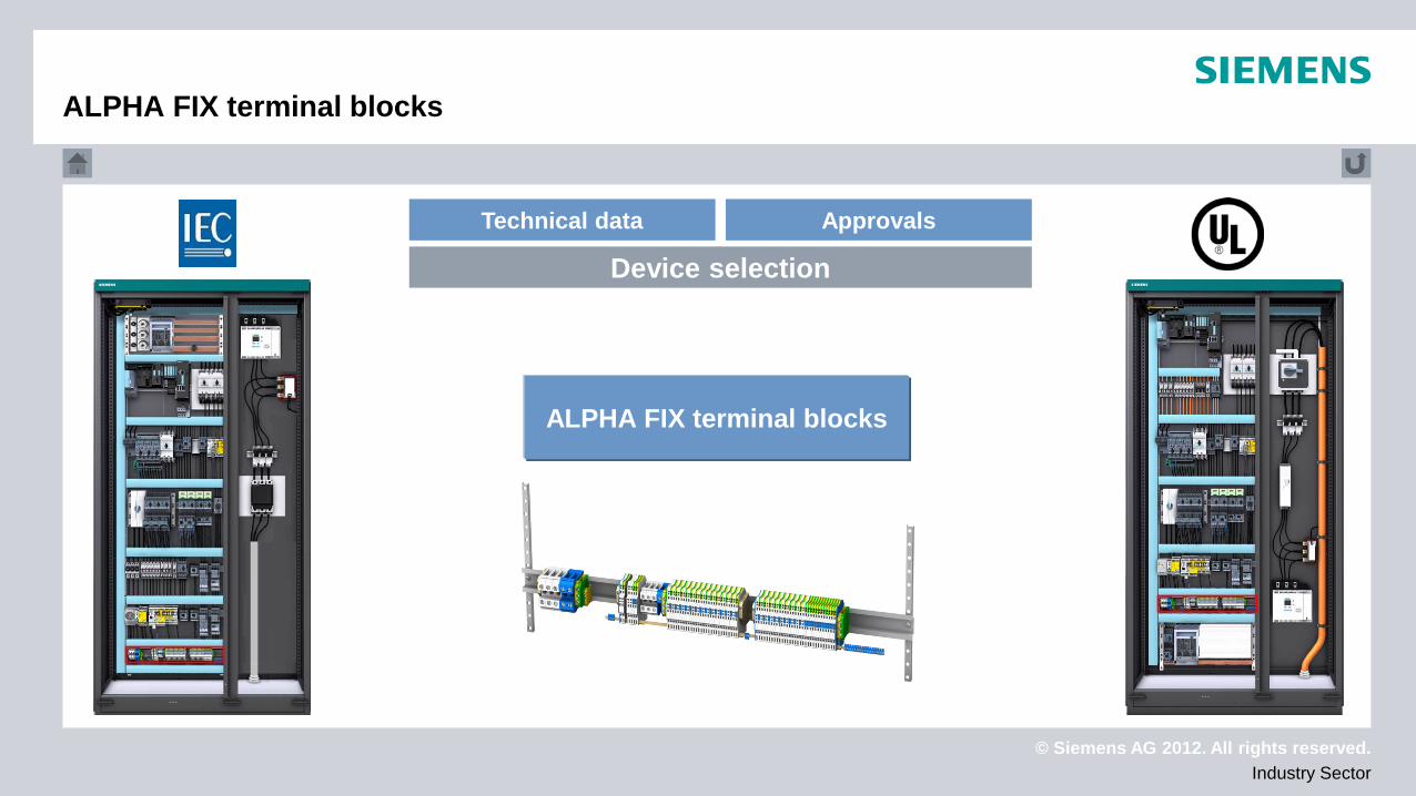
ALPHA FIX terminal blocks
Technical data Approvals
Device selection
ALPHA FIX terminal blocks
© Siemens AG 2012. All rights reserved. Industry Sector
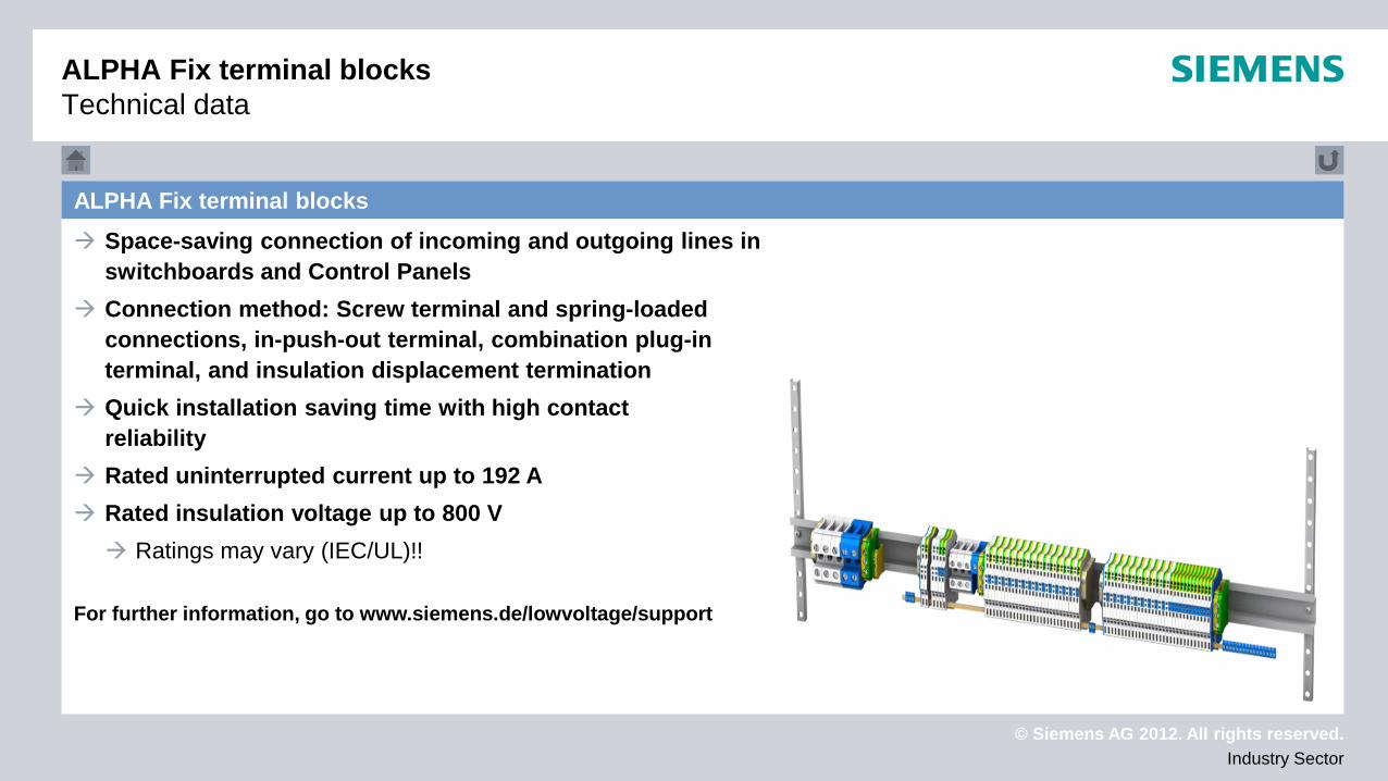
ALPHA Fix terminal blocks Space-saving connection of incoming and outgoing lines in
switchboards and Control Panels Connection method: Screw terminal and spring-loaded
connections, in-push-out terminal, combination plug-in terminal, and insulation displacement termination
Quick installation saving time with high contact reliability
Rated uninterrupted current up to 192 A Rated insulation voltage up to 800 V Ratings may vary (IEC/UL)!!
For further information, go to www.siemens.de/lowvoltage/support
ALPHA Fix terminal blocks Technical data
© Siemens AG 2012. All rights reserved. Industry Sector
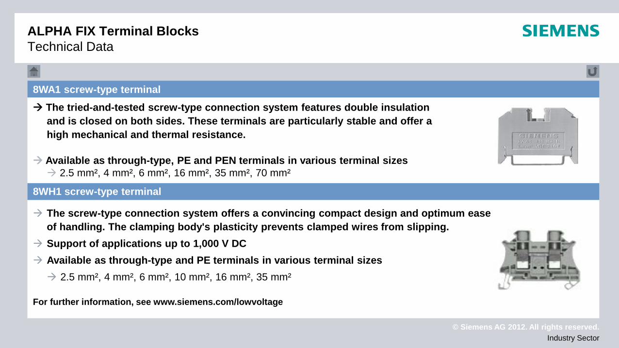
8WA1 screw-type terminal The tried-and-tested screw-type connection system features double insulation
and is closed on both sides. These terminals are particularly stable and offer a high mechanical and thermal resistance.
Available as through-type, PE and PEN terminals in various terminal sizes 2.5 mm², 4 mm², 6 mm², 16 mm², 35 mm², 70 mm² The screw-type connection system offers a convincing compact design and optimum ease
of handling. The clamping body's plasticity prevents clamped wires from slipping. Support of applications up to 1,000 V DC Available as through-type and PE terminals in various terminal sizes 2.5 mm², 4 mm², 6 mm², 10 mm², 16 mm², 35 mm²
For further information, see www.siemens.com/lowvoltage
ALPHA FIX Terminal Blocks Technical Data
8WH1 screw-type terminal
© Siemens AG 2012. All rights reserved. Industry Sector
ALPHA FIX Terminal Blocks Technical Data
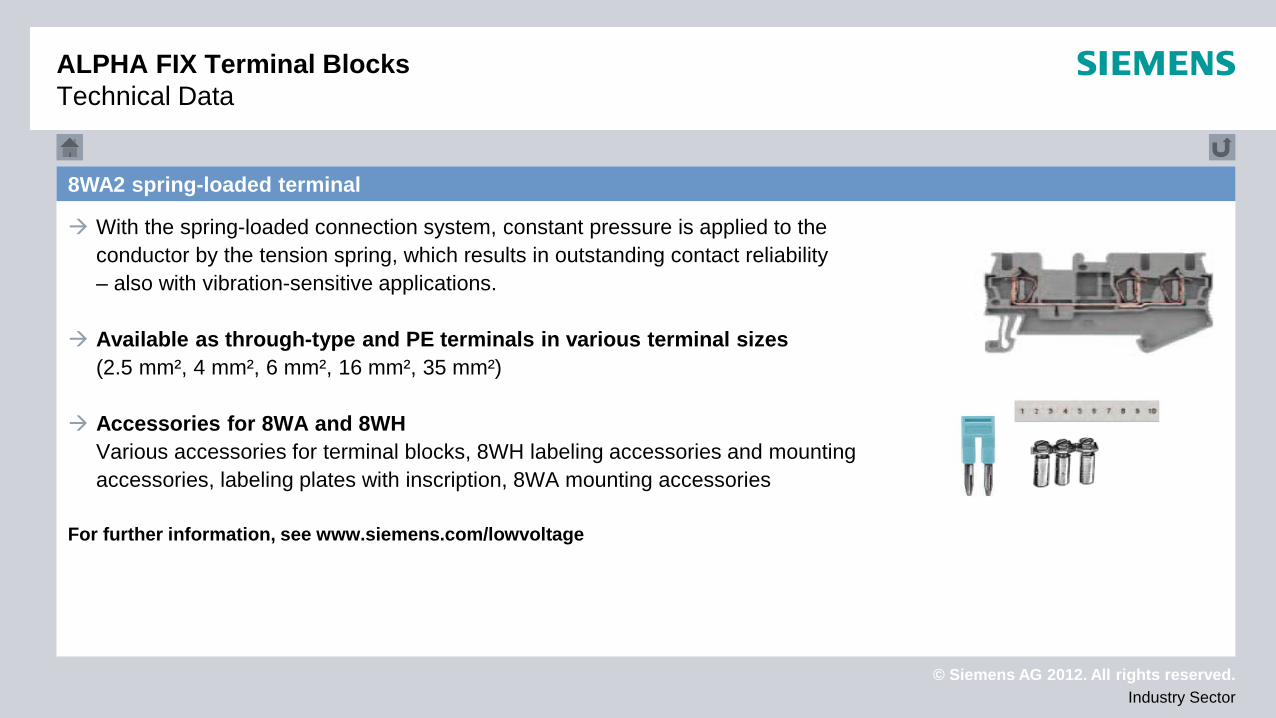
8WA2 spring-loaded terminal
With the spring-loaded connection system, constant pressure is applied to the conductor by the tension spring, which results in outstanding contact reliability – also with vibration-sensitive applications.
Available as through-type and PE terminals in various terminal sizes
(2.5 mm², 4 mm², 6 mm², 16 mm², 35 mm²) Accessories for 8WA and 8WH
Various accessories for terminal blocks, 8WH labeling accessories and mounting accessories, labeling plates with inscription, 8WA mounting accessories
For further information, see www.siemens.com/lowvoltage
© Siemens AG 2012. All rights reserved. Industry Sector
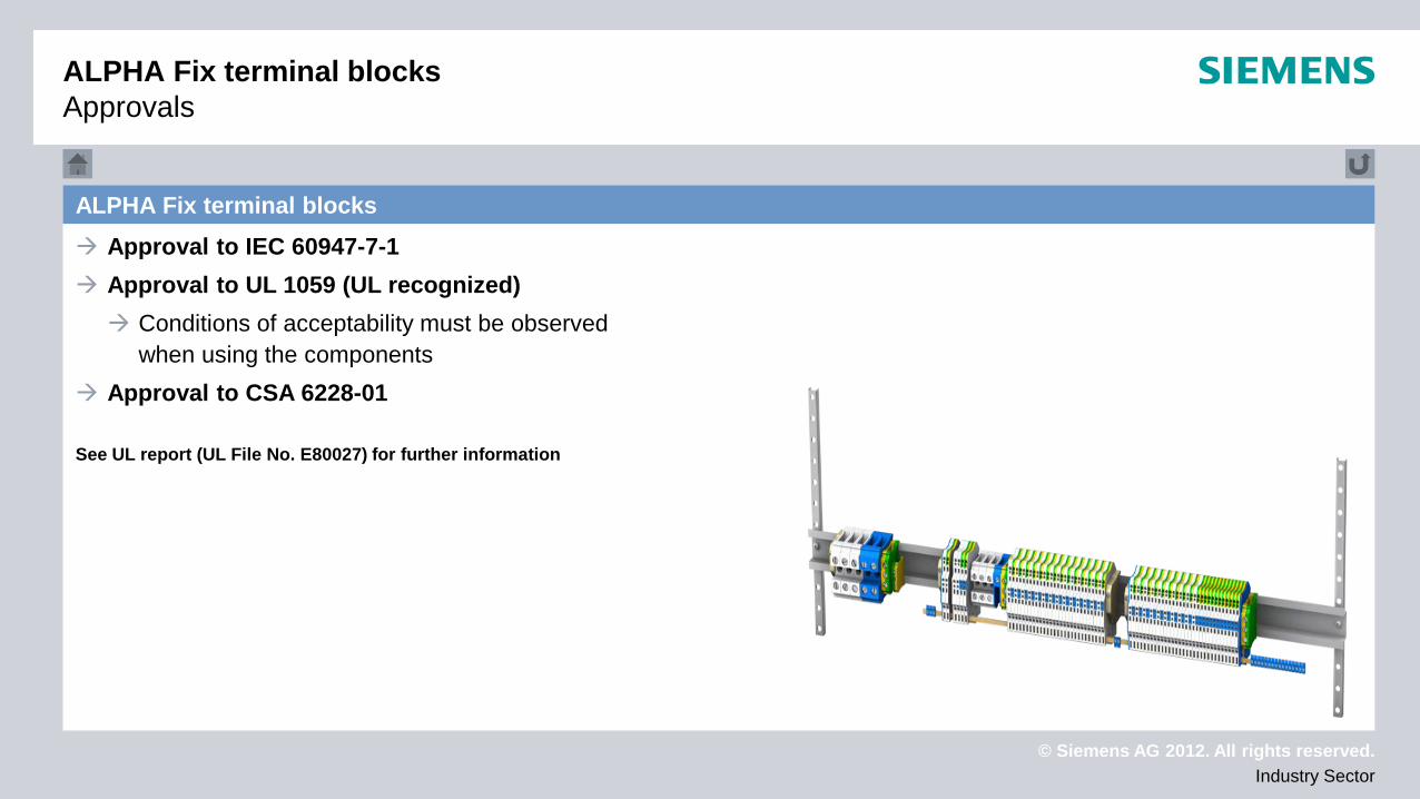
ALPHA Fix terminal blocks Approval to IEC 60947-7-1 Approval to UL 1059 (UL recognized) Conditions of acceptability must be observed
when using the components Approval to CSA 6228-01 See UL report (UL File No. E80027) for further information
ALPHA Fix terminal blocks Approvals
© Siemens AG 2012. All rights reserved. Industry Sector
3RA6 compact starter with 3RA68 infeed system
3RA6 compact starter with 3RA68 infeed system

© Siemens AG 2012. All rights reserved. Industry Sector
3RA6 compact starter with 3RA68 infeed system
3RA6 compact starter with 3RA68 infeed system
© Siemens AG 2012. All rights reserved. Industry Sector
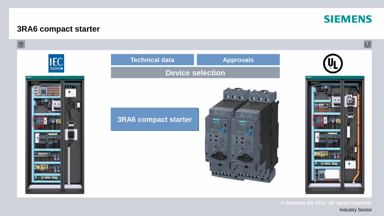
3RA6 compact starter
Technical data Approvals
Device selection
3RA6 compact starter
© Siemens AG 2012. All rights reserved. Industry Sector
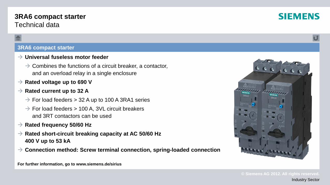
3RA6 compact starter Universal fuseless motor feeder Combines the functions of a circuit breaker, a contactor,
and an overload relay in a single enclosure Rated voltage up to 690 V Rated current up to 32 A For load feeders > 32 A up to 100 A 3RA1 series For load feeders > 100 A, 3VL circuit breakers
and 3RT contactors can be used Rated frequency 50/60 Hz Rated short-circuit breaking capacity at AC 50/60 Hz
400 V up to 53 kA Connection method: Screw terminal connection, spring-loaded connection For further information, go to www.siemens.de/sirius
3RA6 compact starter Technical data
© Siemens AG 2012. All rights reserved. Industry Sector
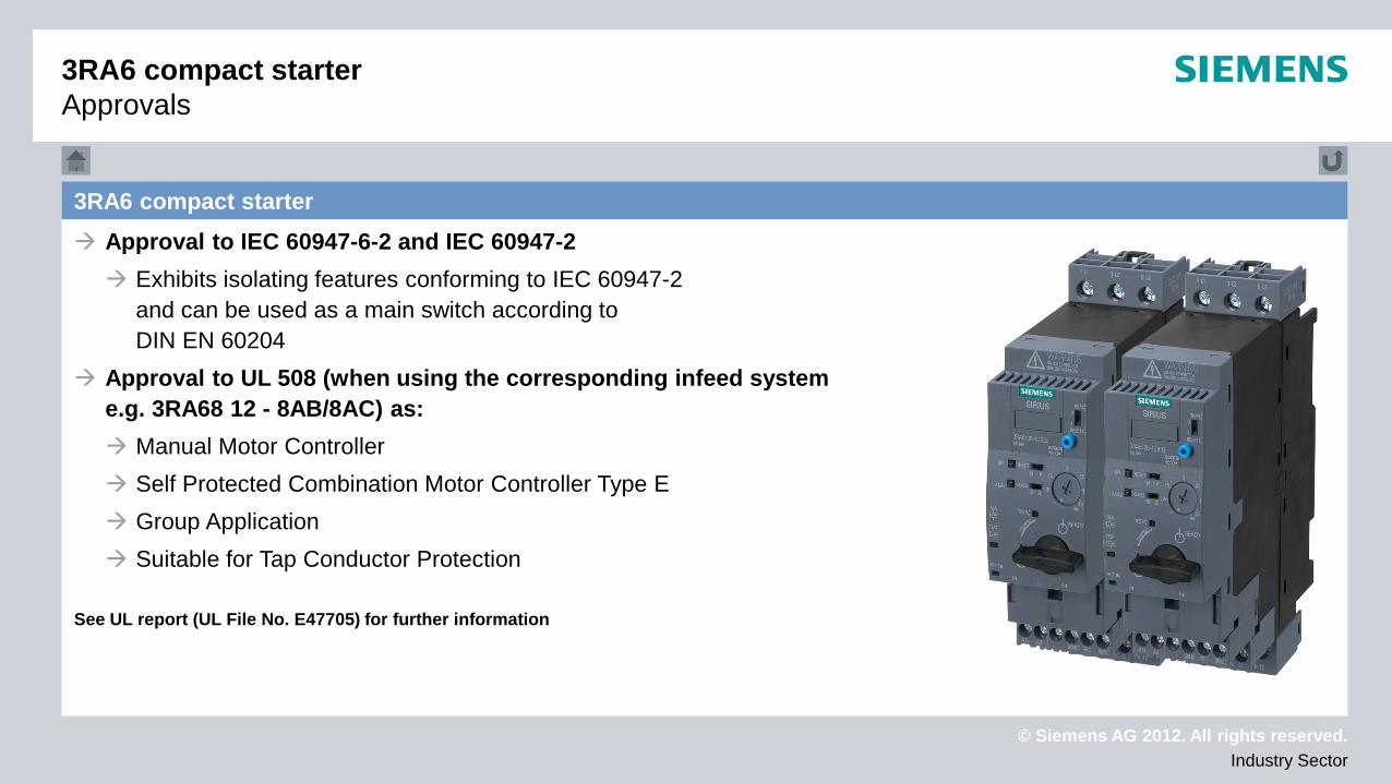
3RA6 compact starter Approval to IEC 60947-6-2 and IEC 60947-2 Exhibits isolating features conforming to IEC 60947-2
and can be used as a main switch according to DIN EN 60204
Approval to UL 508 (when using the corresponding infeed system e.g. 3RA68 12 - 8AB/8AC) as: Manual Motor Controller Self Protected Combination Motor Controller Type E Group Application Suitable for Tap Conductor Protection
See UL report (UL File No. E47705) for further information
3RA6 compact starter Approvals
© Siemens AG 2012. All rights reserved. Industry Sector
Technical data Approvals
Device selection
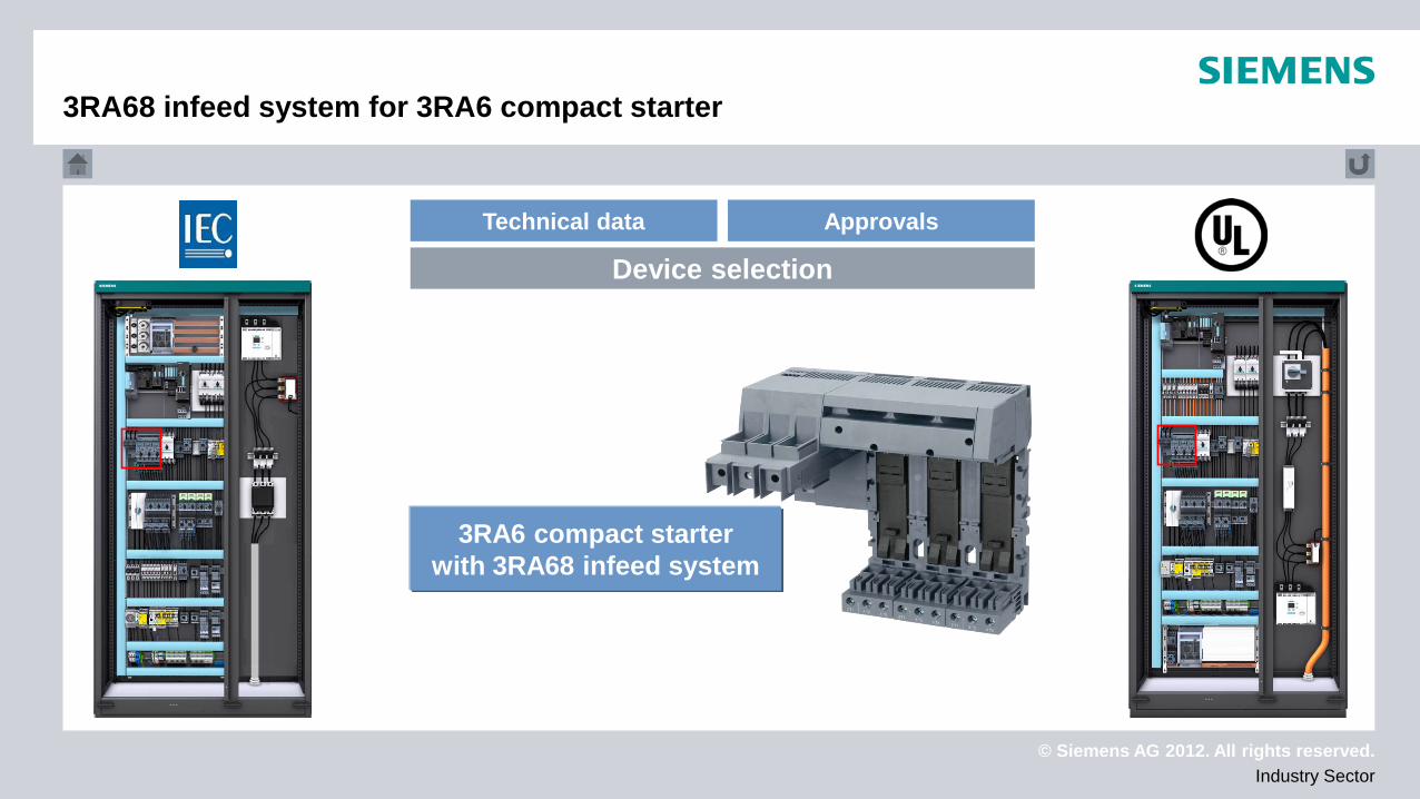
3RA68 infeed system for 3RA6 compact starter
3RA6 compact starter with 3RA68 infeed system
© Siemens AG 2012. All rights reserved. Industry Sector
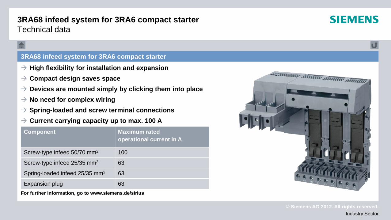
3RA68 infeed system for 3RA6 compact starter High flexibility for installation and expansion Compact design saves space Devices are mounted simply by clicking them into place No need for complex wiring Spring-loaded and screw terminal connections Current carrying capacity up to max. 100 A For further information, go to www.siemens.de/sirius
Component Maximum rated operational current in A
Screw-type infeed 50/70 mm2 100
Screw-type infeed 25/35 mm2 63
Spring-loaded infeed 25/35 mm2 63
Expansion plug 63
3RA68 infeed system for 3RA6 compact starter Technical data
© Siemens AG 2012. All rights reserved. Industry Sector
3RA68 Infeed System for 3RA6 Compact Starter Approvals
3RA68 infeed system for 3RA6 compact starter Approval according to UL 508 for the installation of: Self-protected combination motor controller type E Manual motor controller Group application Suitable for tap conductor protection
Approval according to CAN/CSA-C22.2 No. 0.4-04 Bonding of electrical equipment
Approval according to CSA-C22.2 No. 14-10 Industrial control equipment
See UL report (UL File No. E148698) for further information

© Siemens AG 2012. All rights reserved. Industry Sector
3RA2 load feeder on busbar with infeed
3RA2 load feeder (3RV2 motor starter protector + 3RT2
contactor) on busbar with infeed
© Siemens AG 2012. All rights reserved. Industry Sector
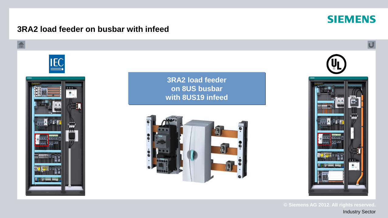
3RA2 load feeder on busbar with infeed
3RA2 load feeder on 8US busbar
with 8US19 infeed
© Siemens AG 2012. All rights reserved. Industry Sector
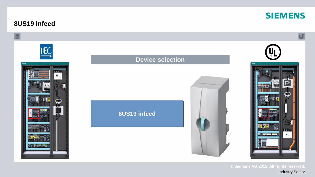
8US19 infeed
Device selection
8US19 infeed
© Siemens AG 2012. All rights reserved. Industry Sector
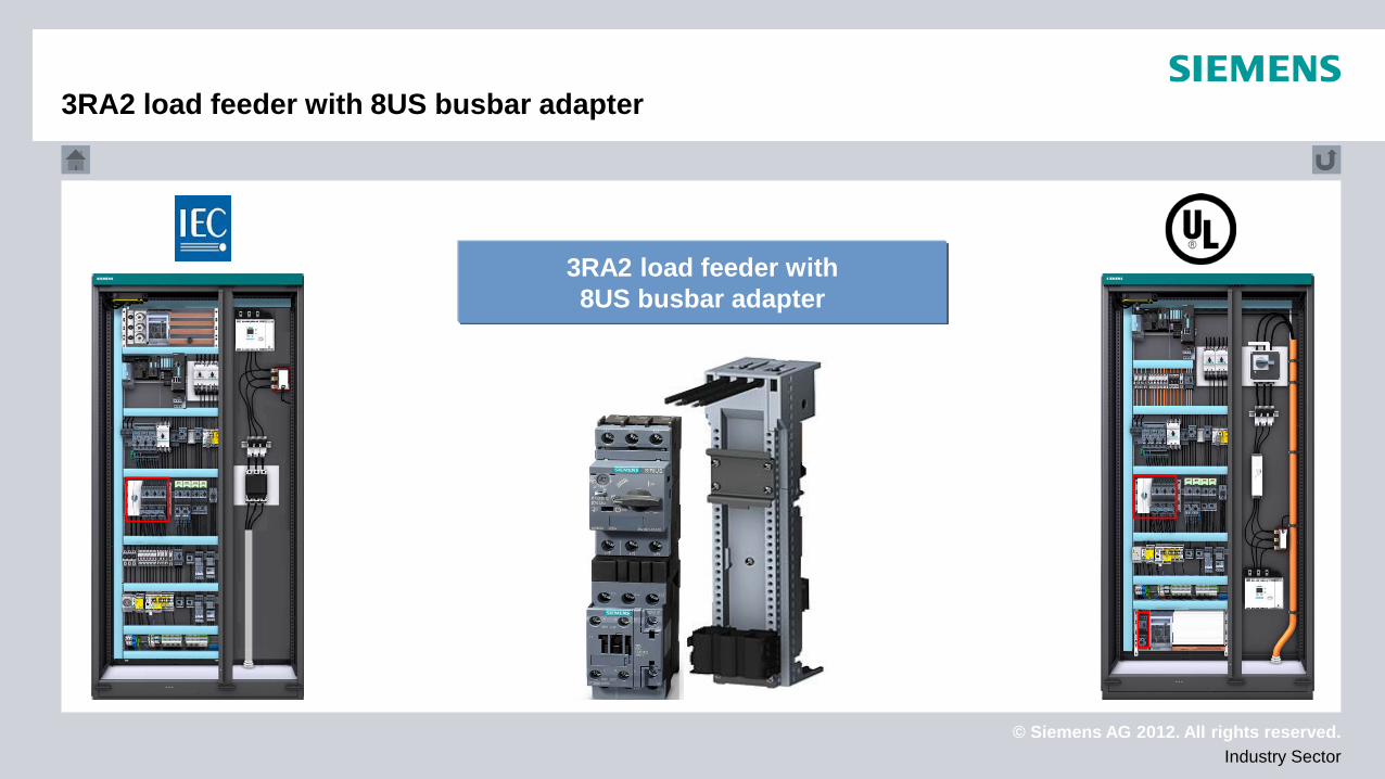
3RA2 load feeder with 8US busbar adapter
3RA2 load feeder with 8US busbar adapter
© Siemens AG 2012. All rights reserved. Industry Sector
3RA2 load feeder 3RV2 circuit breaker + 3RT2 contactor
3RA2 load feeder
© Siemens AG 2012. All rights reserved. Industry Sector
Technical data Approvals
Device selection
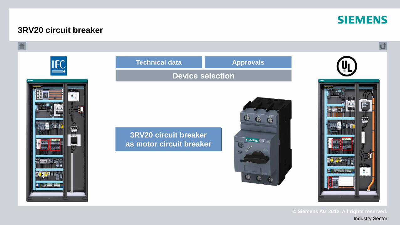
3RV20 circuit breaker
3RV20 circuit breaker as motor circuit breaker
© Siemens AG 2012. All rights reserved. Industry Sector
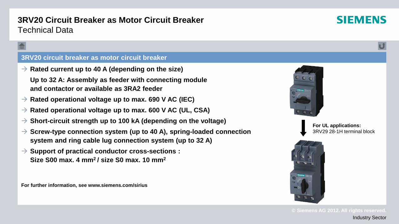
3RV20 circuit breaker as motor circuit breaker Rated current up to 40 A (depending on the size) Up to 32 A: Assembly as feeder with connecting module
and contactor or available as 3RA2 feeder Rated operational voltage up to max. 690 V AC (IEC) Rated operational voltage up to max. 600 V AC (UL, CSA) Short-circuit strength up to 100 kA (depending on the voltage) Screw-type connection system (up to 40 A), spring-loaded connection
system and ring cable lug connection system (up to 32 A) Support of practical conductor cross-sections :
Size S00 max. 4 mm2 / size S0 max. 10 mm2 For further information, see www.siemens.com/sirius
3RV20 Circuit Breaker as Motor Circuit Breaker Technical Data
For UL applications: 3RV29 28-1H terminal block

© Siemens AG 2012. All rights reserved. Industry Sector
3RV20 circuit breaker as motor circuit breaker Approval to IEC 60947-1, IEC 60947-2 and IEC 60947-4-1 as: Short-circuit and motor protection System and transformer protection Main and emergency off protection
Approval to CSA C22.2 No. 14 Approval to UL 508 „Manual Motor Controller“ "Self Protected Combination Motor Controller"
when using 3RV29 28-1H terminal block or 3RV29 28-1K phase barriers
See UL report (UL File No. E47705) for further information
For UL applications: 3RV29 28-1H terminal block
3RV20 circuit breaker as motor circuit breaker Approvals
© Siemens AG 2012. All rights reserved. Industry Sector
Device selection
8US busbar adapter
8US busbar adapter
© Siemens AG 2012. All rights reserved. Industry Sector
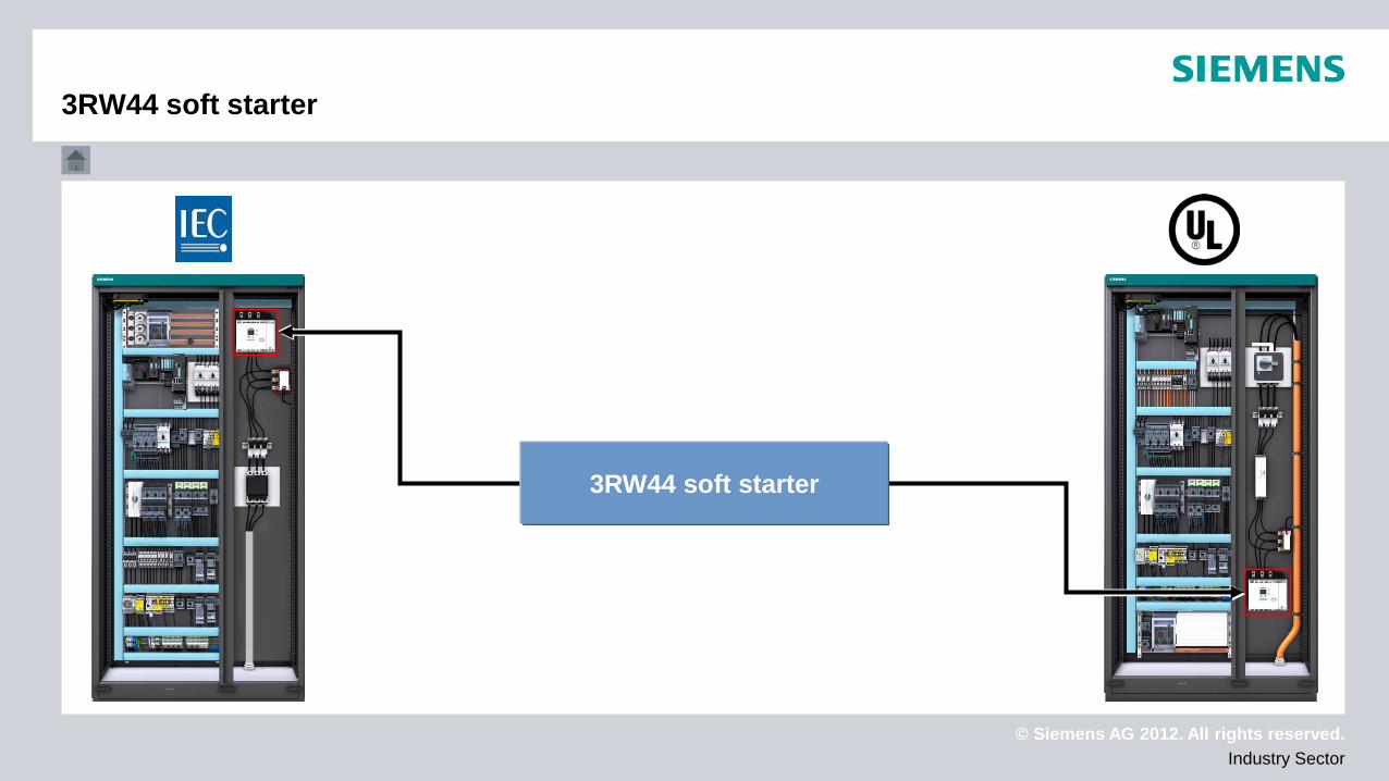
3RW44 soft starter
3RW44 soft starter
© Siemens AG 2012. All rights reserved. Industry Sector
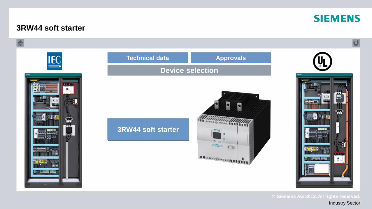
3RW44 soft starter
Technical data Approvals
Device selection
3RW44 soft starter
© Siemens AG 2012. All rights reserved. Industry Sector
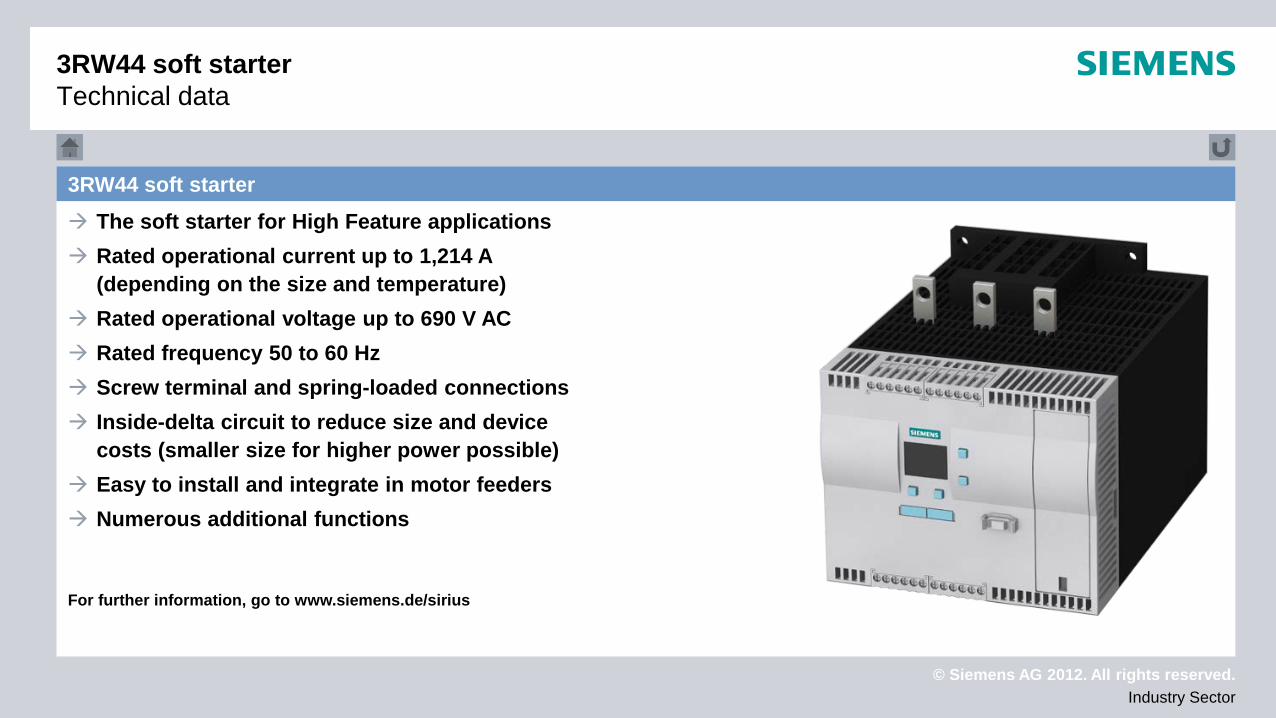
3RW44 soft starter The soft starter for High Feature applications Rated operational current up to 1,214 A
(depending on the size and temperature) Rated operational voltage up to 690 V AC Rated frequency 50 to 60 Hz Screw terminal and spring-loaded connections Inside-delta circuit to reduce size and device
costs (smaller size for higher power possible) Easy to install and integrate in motor feeders Numerous additional functions For further information, go to www.siemens.de/sirius
3RW44 soft starter Technical data
© Siemens AG 2012. All rights reserved. Industry Sector
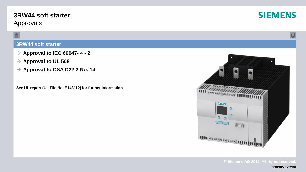
3RW44 soft starter Approval to IEC 60947- 4 - 2 Approval to UL 508 Approval to CSA C22.2 No. 14
See UL report (UL File No. E143112) for further information
3RW44 soft starter Approvals

© Siemens AG 2012. All rights reserved. Industry Sector
SITOR semiconductor fuse
SITOR semiconductor fuse
© Siemens AG 2012. All rights reserved. Industry Sector
Technical data Approvals
Device selection
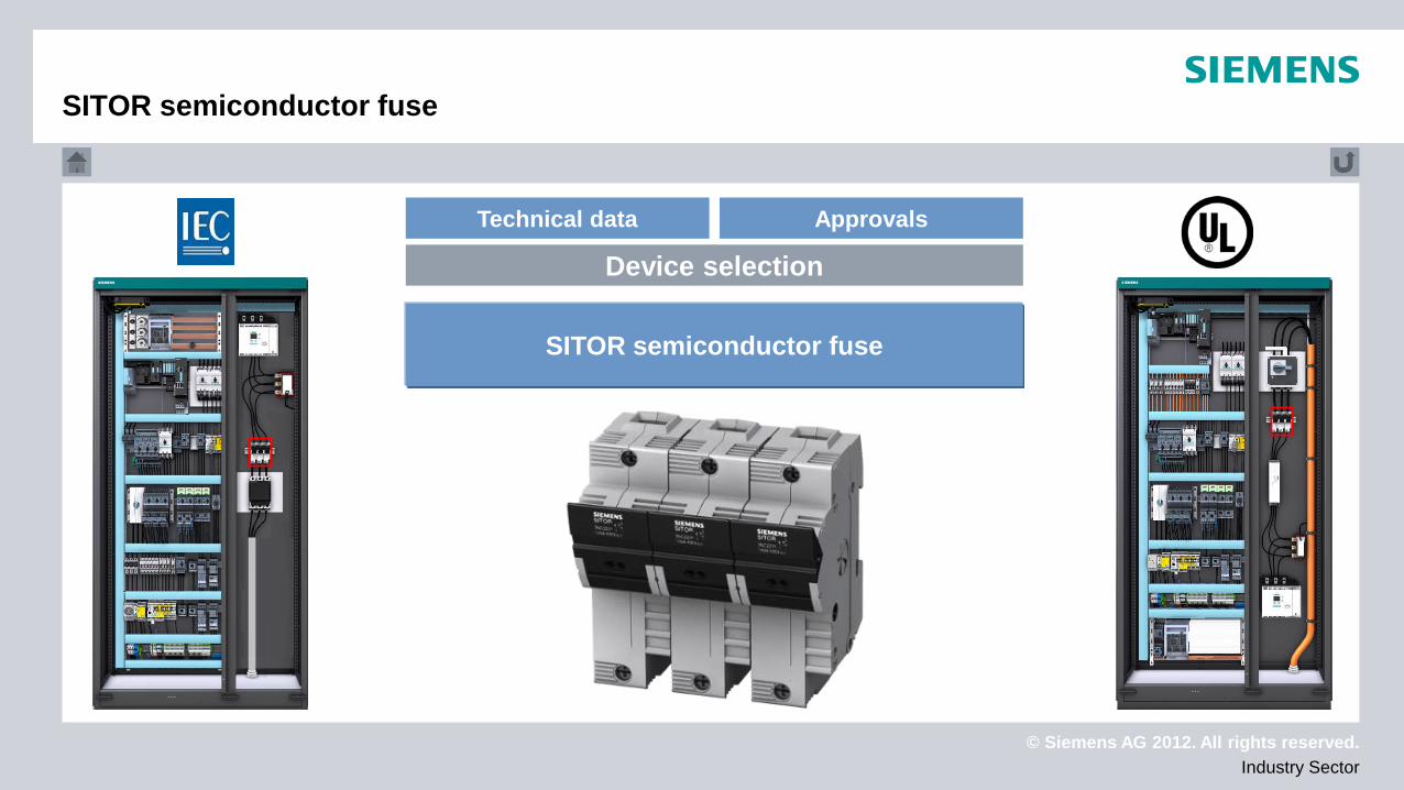
SITOR semiconductor fuse
SITOR semiconductor fuse
© Siemens AG 2012. All rights reserved. Industry Sector
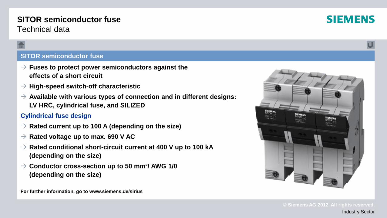
SITOR semiconductor fuse Fuses to protect power semiconductors against the
effects of a short circuit High-speed switch-off characteristic Available with various types of connection and in different designs:
LV HRC, cylindrical fuse, and SILIZED Cylindrical fuse design Rated current up to 100 A (depending on the size) Rated voltage up to max. 690 V AC Rated conditional short-circuit current at 400 V up to 100 kA
(depending on the size) Conductor cross-section up to 50 mm²/ AWG 1/0
(depending on the size) For further information, go to www.siemens.de/sirius
SITOR semiconductor fuse Technical data
© Siemens AG 2012. All rights reserved. Industry Sector
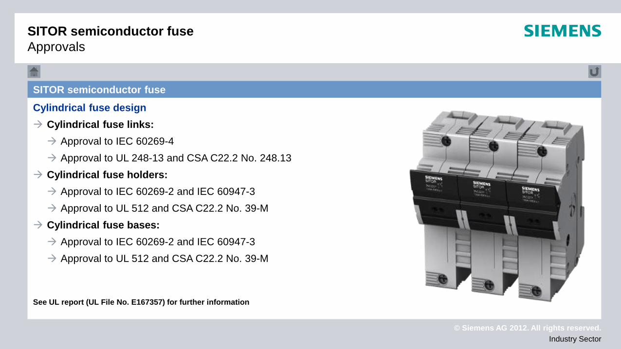
SITOR semiconductor fuse Cylindrical fuse design Cylindrical fuse links: Approval to IEC 60269-4 Approval to UL 248-13 and CSA C22.2 No. 248.13
Cylindrical fuse holders: Approval to IEC 60269-2 and IEC 60947-3 Approval to UL 512 and CSA C22.2 No. 39-M
Cylindrical fuse bases: Approval to IEC 60269-2 and IEC 60947-3 Approval to UL 512 and CSA C22.2 No. 39-M
See UL report (UL File No. E167357) for further information
SITOR semiconductor fuse Approvals
© Siemens AG 2012. All rights reserved. Industry Sector
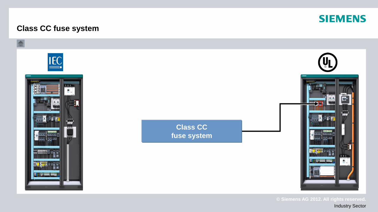
Class CC fuse system
Class CC fuse system
© Siemens AG 2012. All rights reserved. Industry Sector
Technical data Approvals
Device selection
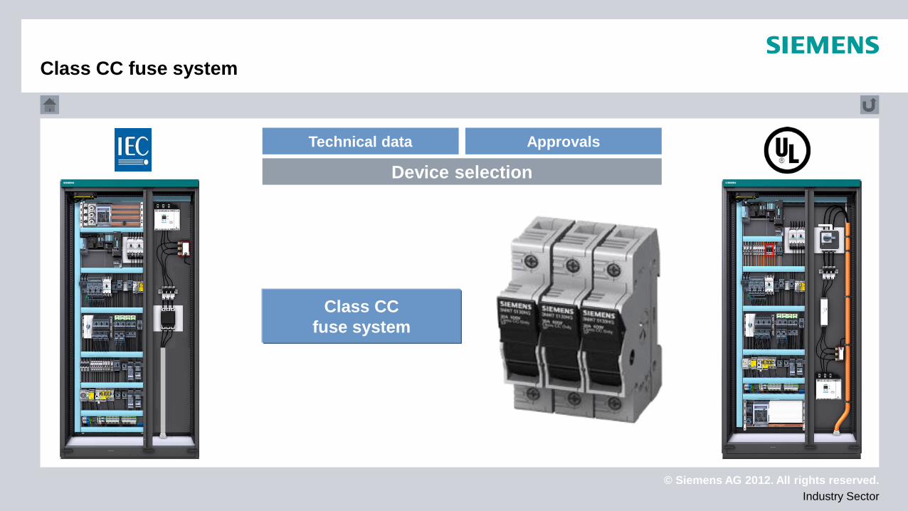
Class CC fuse system
Class CC fuse system
© Siemens AG 2012. All rights reserved. Industry Sector
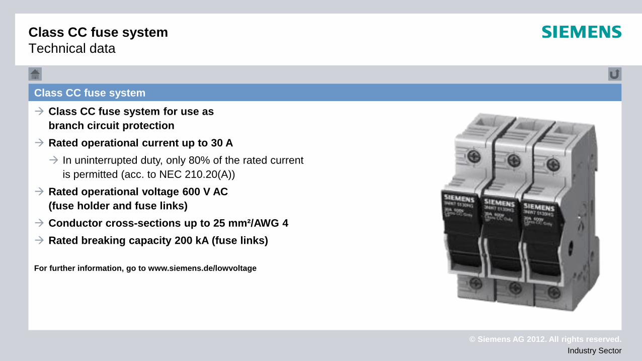
Class CC fuse system Class CC fuse system for use as
branch circuit protection Rated operational current up to 30 A In uninterrupted duty, only 80% of the rated current
is permitted (acc. to NEC 210.20(A)) Rated operational voltage 600 V AC
(fuse holder and fuse links) Conductor cross-sections up to 25 mm²/AWG 4 Rated breaking capacity 200 kA (fuse links) For further information, go to www.siemens.de/lowvoltage
Class CC fuse system Technical data

© Siemens AG 2012. All rights reserved. Industry Sector
Class CC fuse system Approval to UL 512 (fuse holders) Approval to UL 248-4 (fuse links) Approval to CSA C22.2 No. 14 No IEC approval!! See UL report (UL File No. E258218) for further information
Class CC fuse system Approvals
© Siemens AG 2012. All rights reserved. Industry Sector
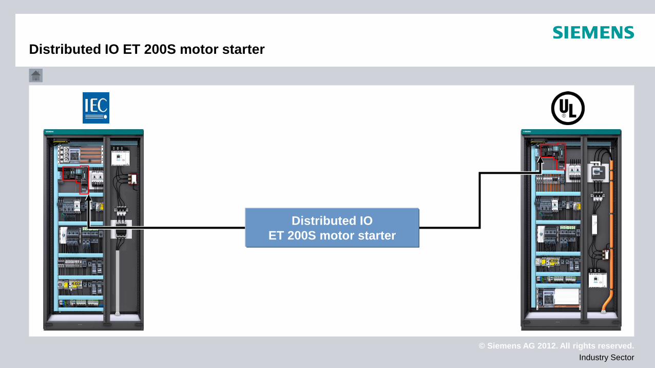
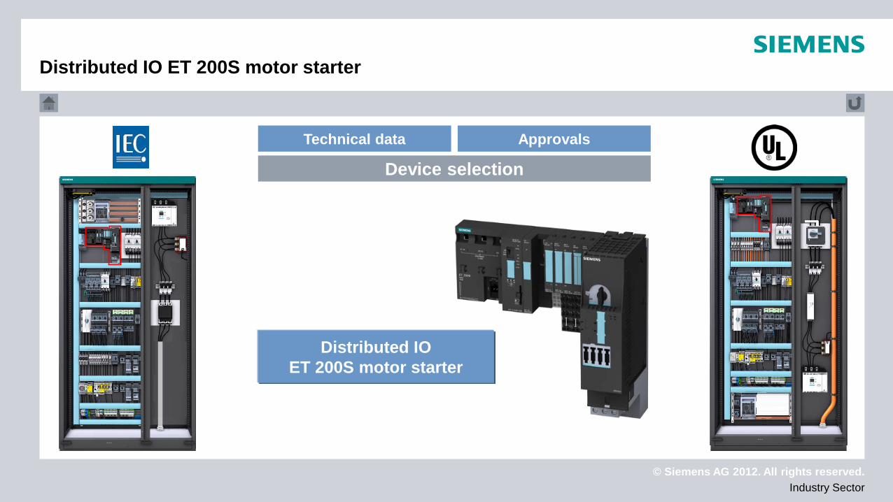
Distributed IO ET 200S motor starter
Distributed IO ET 200S motor starter
© Siemens AG 2012. All rights reserved. Industry Sector
Technical data Approvals
Device selection
Distributed IO ET 200S motor starter
Distributed IO ET 200S motor starter
© Siemens AG 2012. All rights reserved. Industry Sector
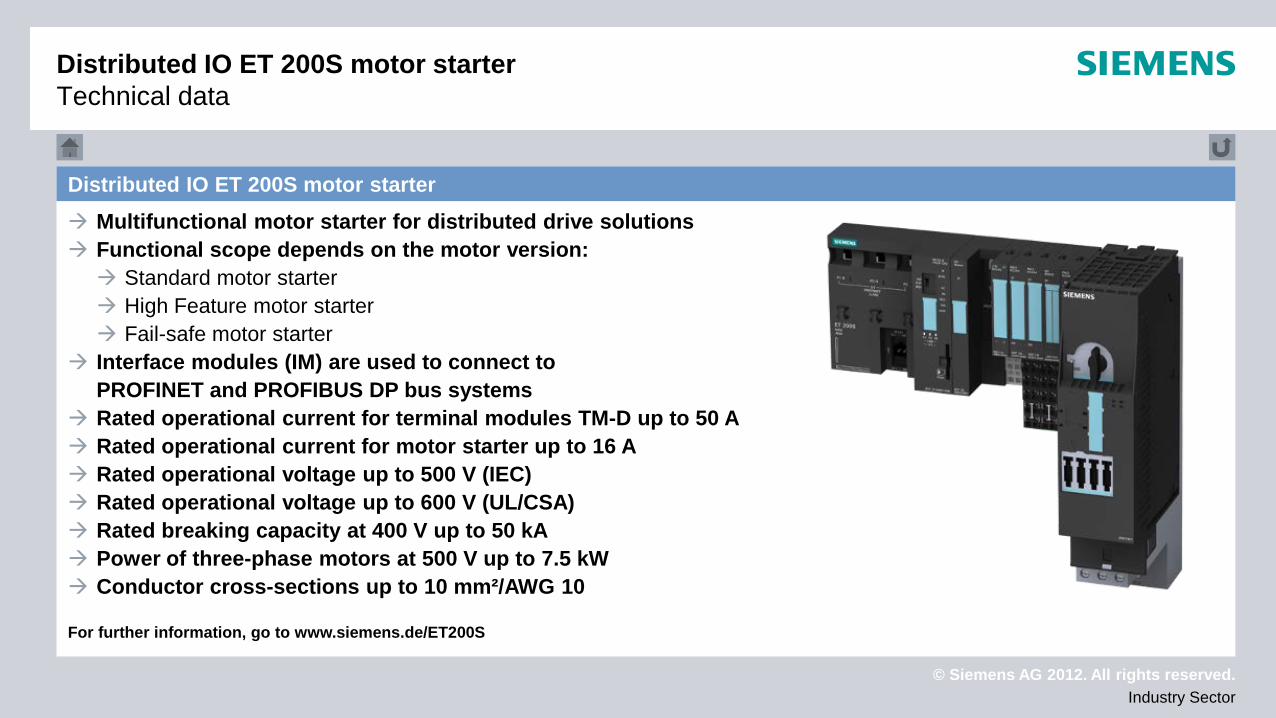
Distributed IO ET 200S motor starter Multifunctional motor starter for distributed drive solutions Functional scope depends on the motor version: Standard motor starter High Feature motor starter Fail-safe motor starter
Interface modules (IM) are used to connect to PROFINET and PROFIBUS DP bus systems
Rated operational current for terminal modules TM-D up to 50 A Rated operational current for motor starter up to 16 A Rated operational voltage up to 500 V (IEC) Rated operational voltage up to 600 V (UL/CSA) Rated breaking capacity at 400 V up to 50 kA Power of three-phase motors at 500 V up to 7.5 kW Conductor cross-sections up to 10 mm²/AWG 10 For further information, go to www.siemens.de/ET200S
Distributed IO ET 200S motor starter Technical data
© Siemens AG 2012. All rights reserved. Industry Sector
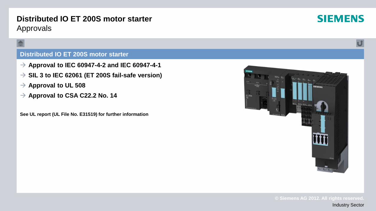
Distributed IO ET 200S motor starter Approval to IEC 60947-4-2 and IEC 60947-4-1 SIL 3 to IEC 62061 (ET 200S fail-safe version) Approval to UL 508 Approval to CSA C22.2 No. 14 See UL report (UL File No. E31519) for further information
Distributed IO ET 200S motor starter Approvals
© Siemens AG 2012. All rights reserved. Industry Sector
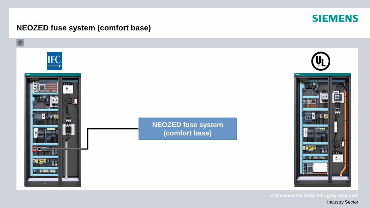
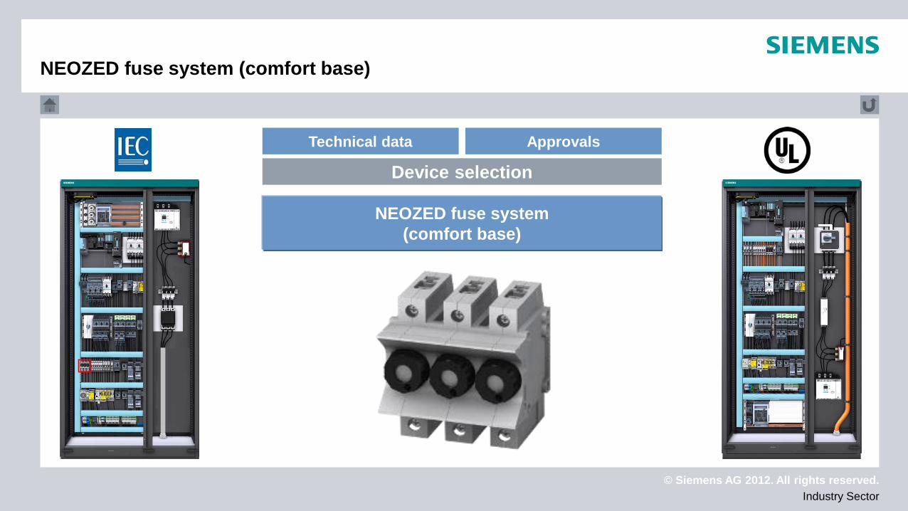
NEOZED fuse system (comfort base)
NEOZED fuse system (comfort base)
© Siemens AG 2012. All rights reserved. Industry Sector
NEOZED fuse system (comfort base)
Technical data Approvals
Device selection
NEOZED fuse system (comfort base)
© Siemens AG 2012. All rights reserved. Industry Sector
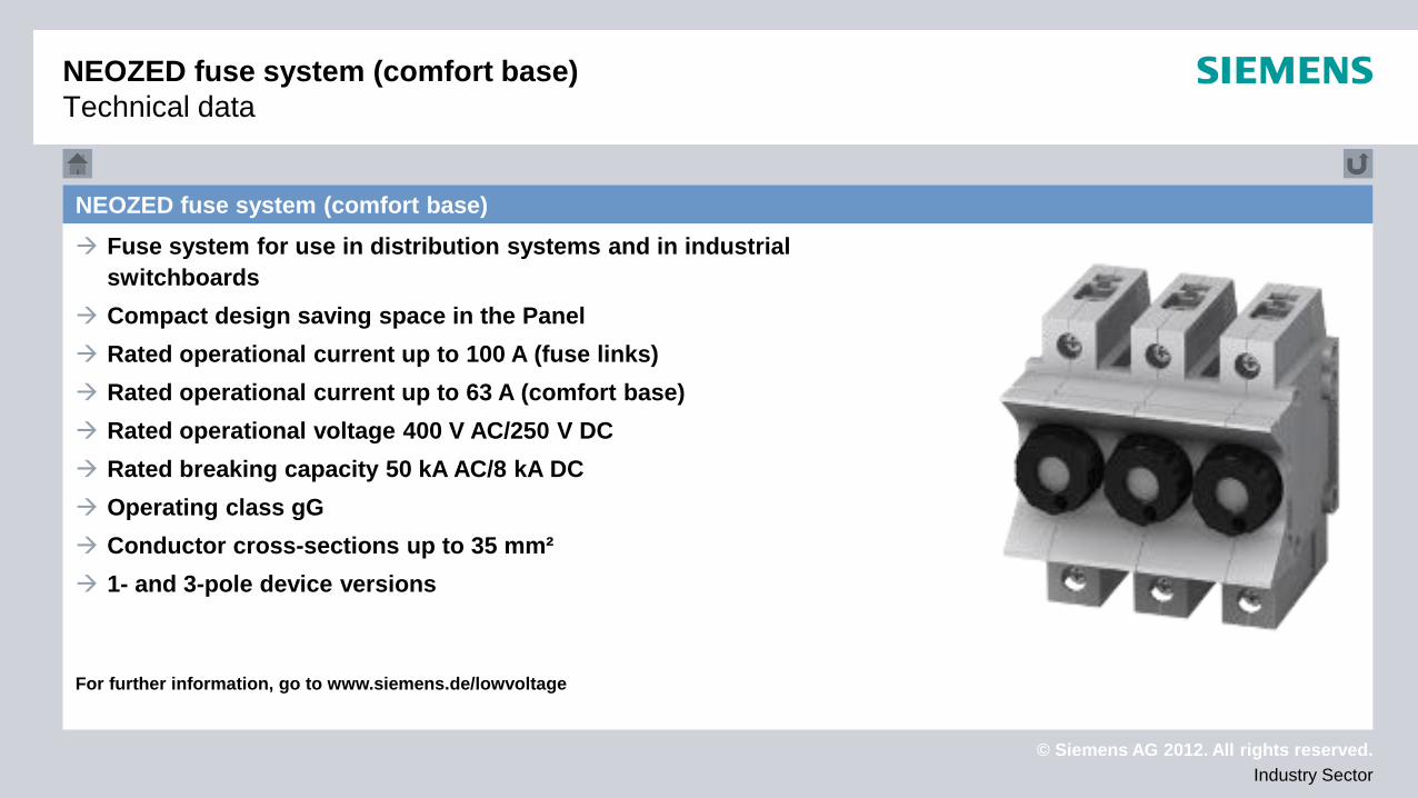
NEOZED fuse system (comfort base) Fuse system for use in distribution systems and in industrial
switchboards Compact design saving space in the Panel Rated operational current up to 100 A (fuse links) Rated operational current up to 63 A (comfort base) Rated operational voltage 400 V AC/250 V DC Rated breaking capacity 50 kA AC/8 kA DC Operating class gG Conductor cross-sections up to 35 mm² 1- and 3-pole device versions For further information, go to www.siemens.de/lowvoltage
NEOZED fuse system (comfort base) Technical data

© Siemens AG 2012. All rights reserved. Industry Sector
NEOZED fuse system (comfort base) Fuse links: Approval to IEC 60269-3 Approval to DIN VDE 0636-3
Comfort base: Approval to IEC 60269-3 Approval to DIN VDE 0636-3
No UL/CSA approval!
NEOZED fuse system (comfort base) Approvals
© Siemens AG 2012. All rights reserved. Industry Sector
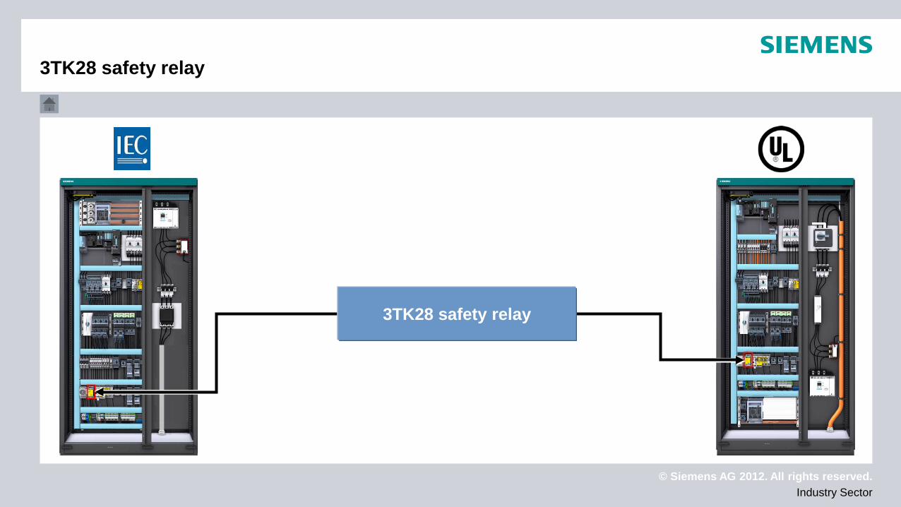
3TK28 safety relay
3TK28 safety relay
© Siemens AG 2012. All rights reserved. Industry Sector
Technical data Approvals
Device selection
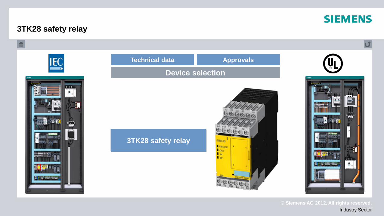
3TK28 safety relay
3TK28 safety relay
© Siemens AG 2012. All rights reserved. Industry Sector
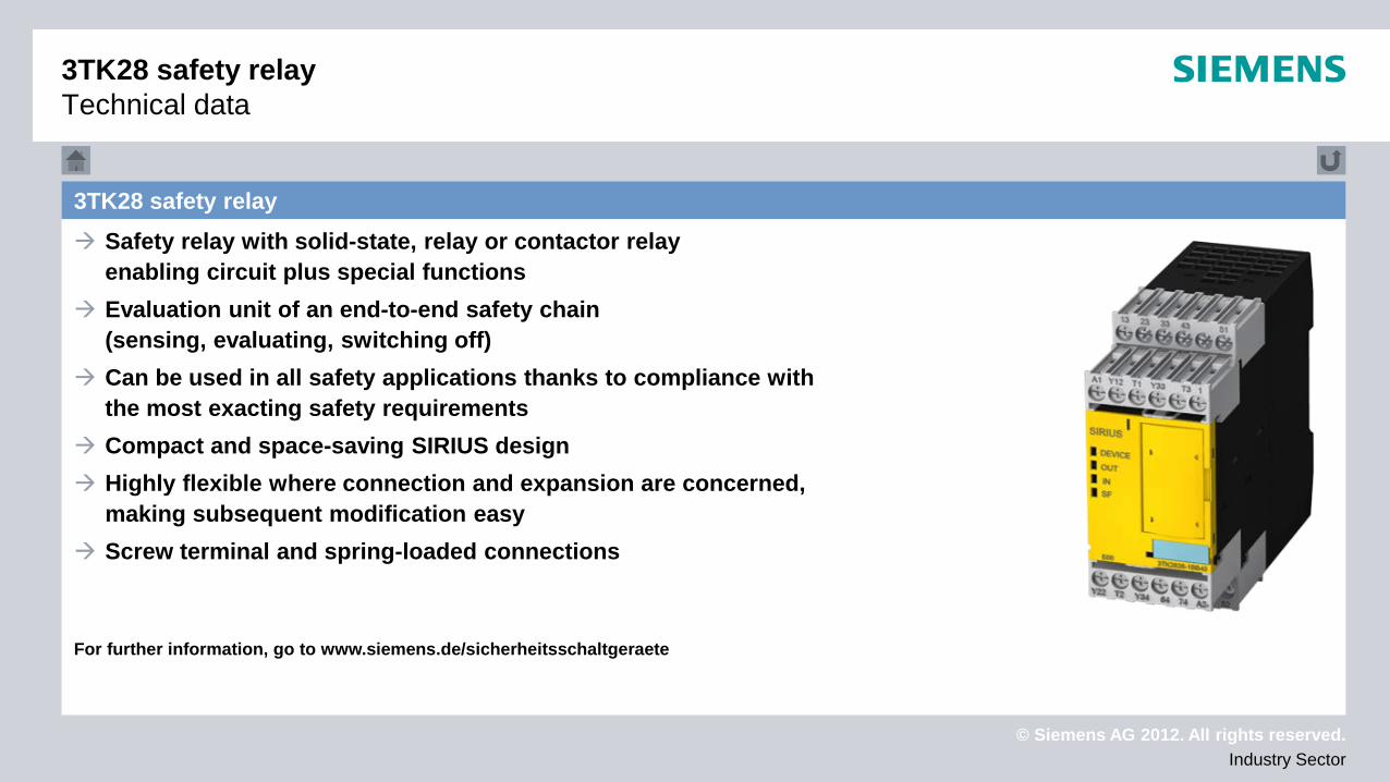
3TK28 safety relay Safety relay with solid-state, relay or contactor relay
enabling circuit plus special functions Evaluation unit of an end-to-end safety chain
(sensing, evaluating, switching off) Can be used in all safety applications thanks to compliance with
the most exacting safety requirements Compact and space-saving SIRIUS design Highly flexible where connection and expansion are concerned,
making subsequent modification easy Screw terminal and spring-loaded connections For further information, go to www.siemens.de/sicherheitsschaltgeraete
3TK28 safety relay Technical data
© Siemens AG 2012. All rights reserved. Industry Sector
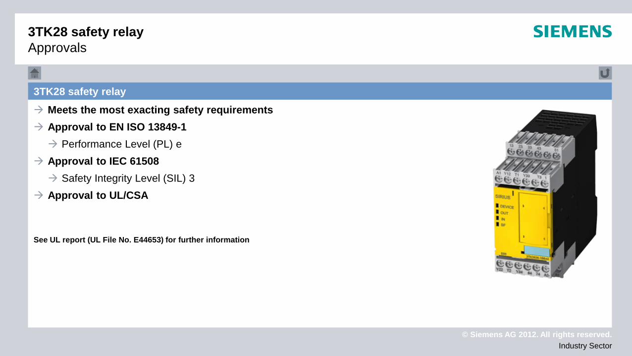
3TK28 safety relay Meets the most exacting safety requirements Approval to EN ISO 13849-1 Performance Level (PL) e
Approval to IEC 61508 Safety Integrity Level (SIL) 3
Approval to UL/CSA See UL report (UL File No. E44653) for further information
3TK28 safety relay Approvals

© Siemens AG 2012. All rights reserved. Industry Sector
3RK3 modular safety system
Modular safety system 3RK3
© Siemens AG 2012. All rights reserved. Industry Sector
3RK3 modular safety system
Technical data Approvals
Device selection
3RK3 modular safety system

© Siemens AG 2012. All rights reserved. Industry Sector
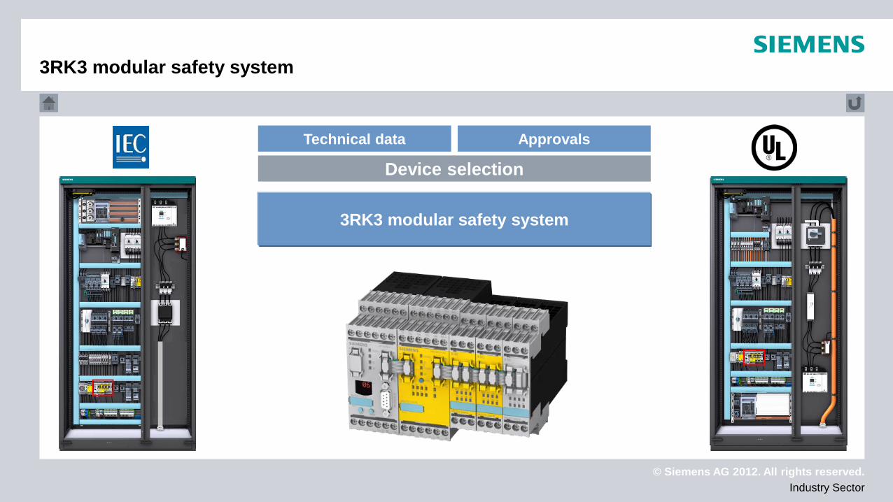
3RK3 modular safety system The MSS 3RK3 is a freely parameterizable modular
safety relay comprising: Central unit (in Basic or Advanced design) Expansion module (I/O module) Interface module (PROFIBUS DP interface) Operating and monitoring module (diagnostics module)
High flexibility and reliability in terms of planning thanks to modular design
Compact and space-saving SIRIUS design Screw-type and spring-loaded connection system Direct-data exchange between multiple MSS units Distribution of sensors and actuators possible via AS-Interface For further information, see www.siemens.com/sirius-mms
3RK3 Modular Safety System Technical Data
© Siemens AG 2012. All rights reserved. Industry Sector
3TK28 safety relay Approvals
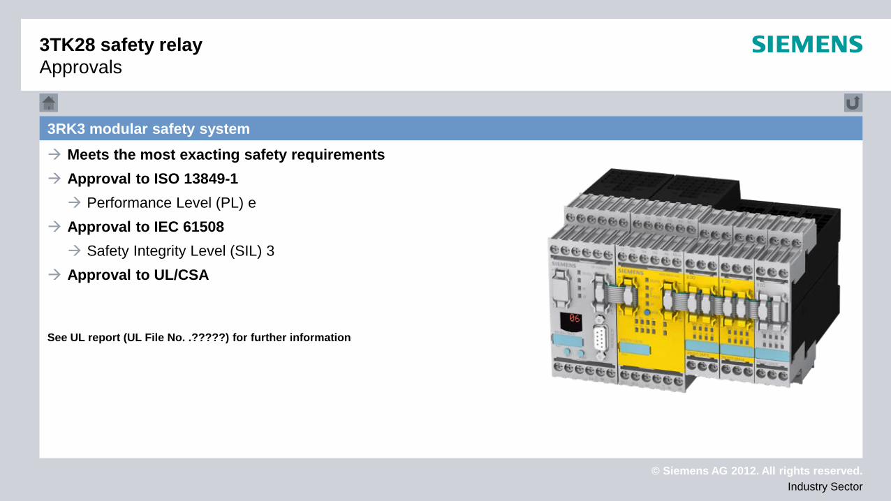
3RK3 modular safety system Meets the most exacting safety requirements Approval to ISO 13849-1 Performance Level (PL) e
Approval to IEC 61508 Safety Integrity Level (SIL) 3
Approval to UL/CSA See UL report (UL File No. .?????) for further information
© Siemens AG 2012. All rights reserved. Industry Sector
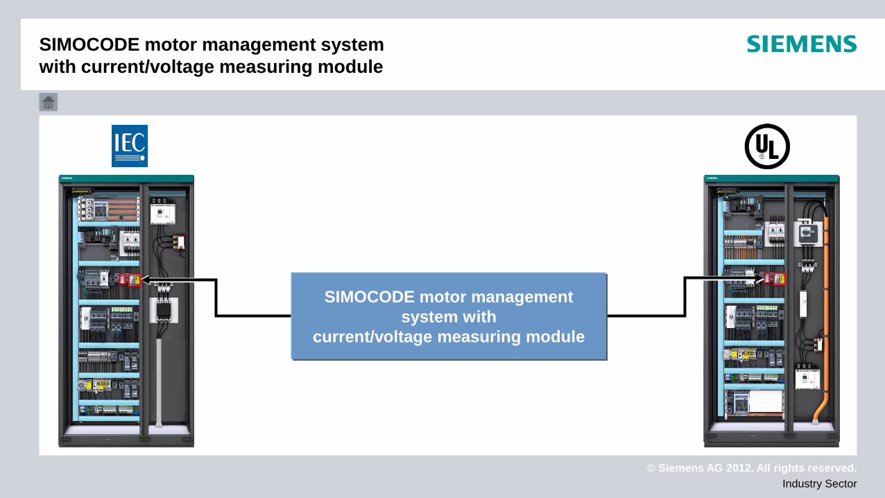
SIMOCODE motor management system with
current/voltage measuring module
SIMOCODE motor management system with current/voltage measuring module

© Siemens AG 2012. All rights reserved. Industry Sector
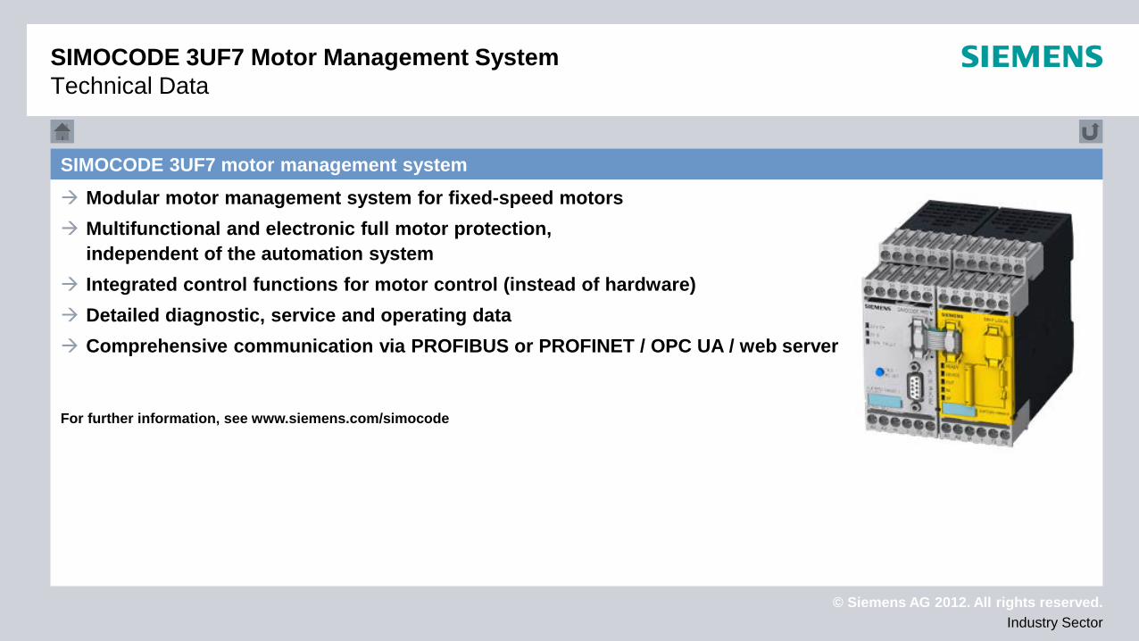
SIMOCODE 3UF7 motor management system
SIMOCODE 3UF7 motor management system
Technical data Approvals
Device selection
© Siemens AG 2012. All rights reserved. Industry Sector
SIMOCODE 3UF7 motor management system Modular motor management system for fixed-speed motors Multifunctional and electronic full motor protection,
independent of the automation system Integrated control functions for motor control (instead of hardware) Detailed diagnostic, service and operating data Comprehensive communication via PROFIBUS or PROFINET / OPC UA / web server For further information, see www.siemens.com/simocode
SIMOCODE 3UF7 Motor Management System Technical Data
© Siemens AG 2012. All rights reserved. Industry Sector
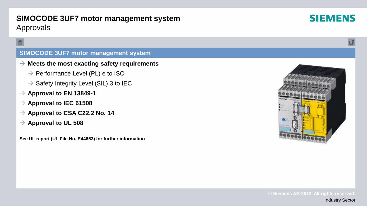
SIMOCODE 3UF7 motor management system Meets the most exacting safety requirements Performance Level (PL) e to ISO Safety Integrity Level (SIL) 3 to IEC
Approval to EN 13849-1 Approval to IEC 61508 Approval to CSA C22.2 No. 14 Approval to UL 508 See UL report (UL File No. E44653) for further information
SIMOCODE 3UF7 motor management system Approvals
© Siemens AG 2012. All rights reserved. Industry Sector
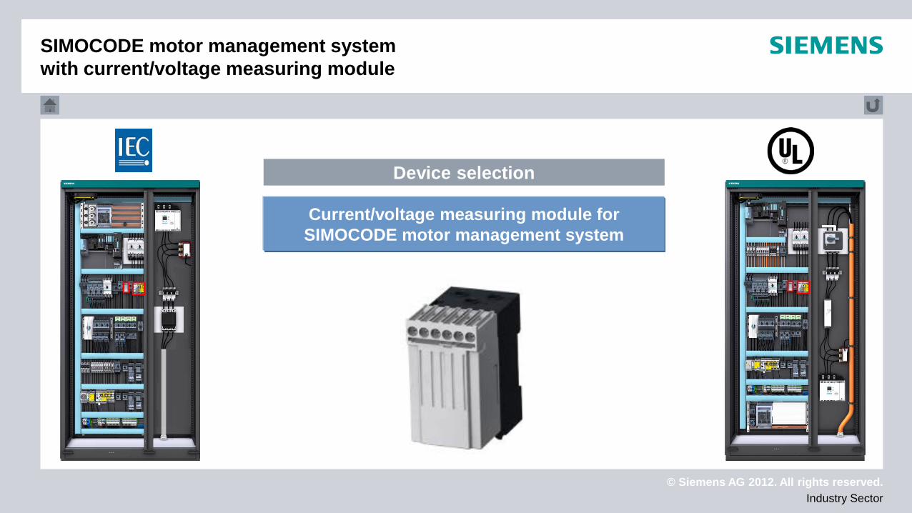
Current/voltage measuring module for SIMOCODE motor management system
Device selection
SIMOCODE motor management system with current/voltage measuring module
© Siemens AG 2012. All rights reserved. Industry Sector
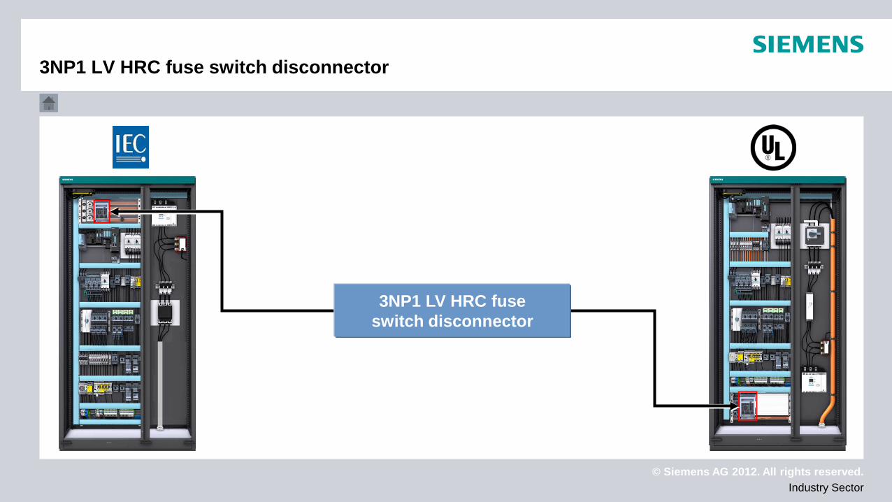
3NP1 LV HRC fuse switch disconnector
3NP1 LV HRC fuse switch disconnector
© Siemens AG 2012. All rights reserved. Industry Sector
Technical data Approvals
Device selection
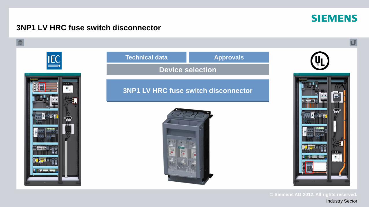
3NP1 LV HRC fuse switch disconnector
3NP1 LV HRC fuse switch disconnector

© Siemens AG 2012. All rights reserved. Industry Sector
3NP1 LV HRC fuse switch disconnector Fuse switch disconnector for the protection and switching of
many different types of load including: Combination motor controllers In conjunction with SITOR fuses for the protection of
frequency converters and soft starters Protection of communication modules Group protection of small loads
Rated operational current up to 630 A Rated operational voltage up to 690 V AC Rated frequency 50/60 Hz Short-circuit strength at 690 V up to 120 kA For further information, go to www.siemens.de/lowvoltage
3NP1 LV HRC fuse switch disconnector Technical data
© Siemens AG 2012. All rights reserved. Industry Sector
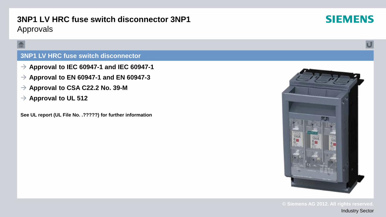
3NP1 LV HRC fuse switch disconnector Approval to IEC 60947-1 and IEC 60947-1 Approval to EN 60947-1 and EN 60947-3 Approval to CSA C22.2 No. 39-M Approval to UL 512 See UL report (UL File No. .?????) for further information
3NP1 LV HRC fuse switch disconnector 3NP1 Approvals
© Siemens AG 2012. All rights reserved. Industry Sector
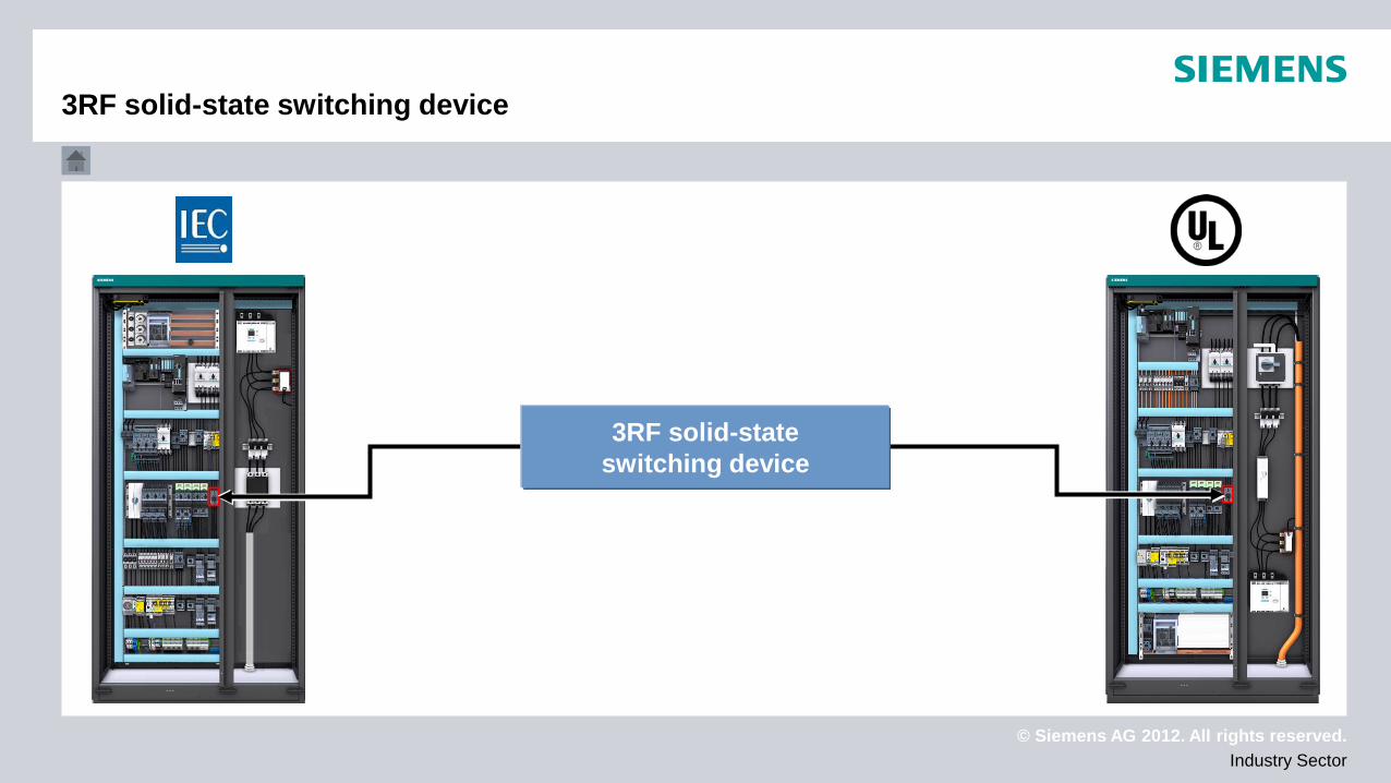
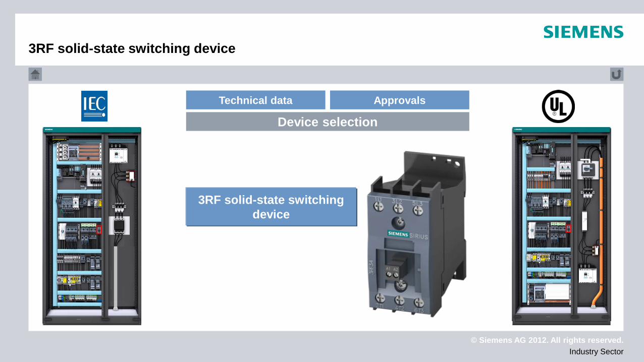
3RF solid-state switching device
3RF solid-state switching device
© Siemens AG 2012. All rights reserved. Industry Sector
Technical data Approvals
Device selection
3RF solid-state switching device
3RF solid-state switching device
© Siemens AG 2012. All rights reserved. Industry Sector
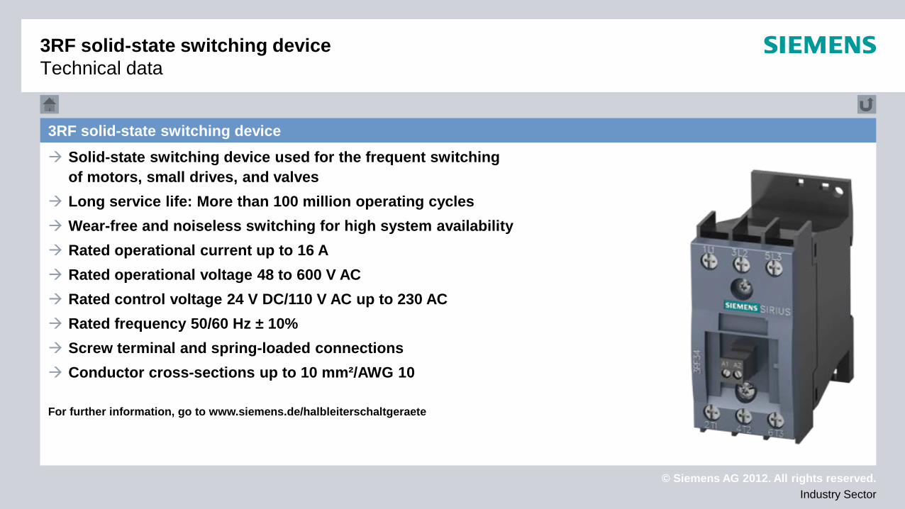
3RF solid-state switching device Solid-state switching device used for the frequent switching
of motors, small drives, and valves Long service life: More than 100 million operating cycles Wear-free and noiseless switching for high system availability Rated operational current up to 16 A Rated operational voltage 48 to 600 V AC Rated control voltage 24 V DC/110 V AC up to 230 AC Rated frequency 50/60 Hz ± 10% Screw terminal and spring-loaded connections Conductor cross-sections up to 10 mm²/AWG 10 For further information, go to www.siemens.de/halbleiterschaltgeraete
3RF solid-state switching device Technical data
© Siemens AG 2012. All rights reserved. Industry Sector
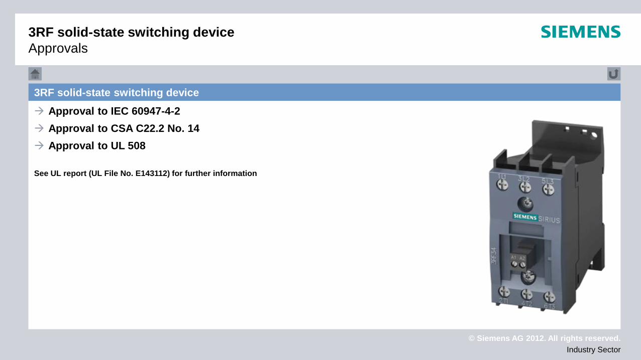
3RF solid-state switching device Approval to IEC 60947-4-2 Approval to CSA C22.2 No. 14 Approval to UL 508 See UL report (UL File No. E143112) for further information
3RF solid-state switching device Approvals
© Siemens AG 2012. All rights reserved. Industry Sector
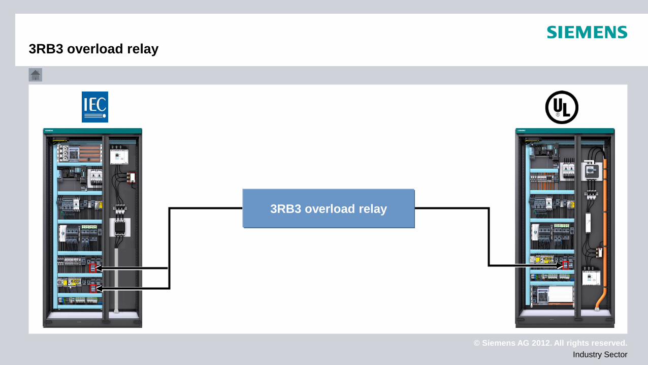
3RB3 overload relay
3RB3 overload relay

© Siemens AG 2012. All rights reserved. Industry Sector
3RB3 overload relay
3RB3 overload relay
Technical data Approvals
Device selection
© Siemens AG 2012. All rights reserved. Industry Sector
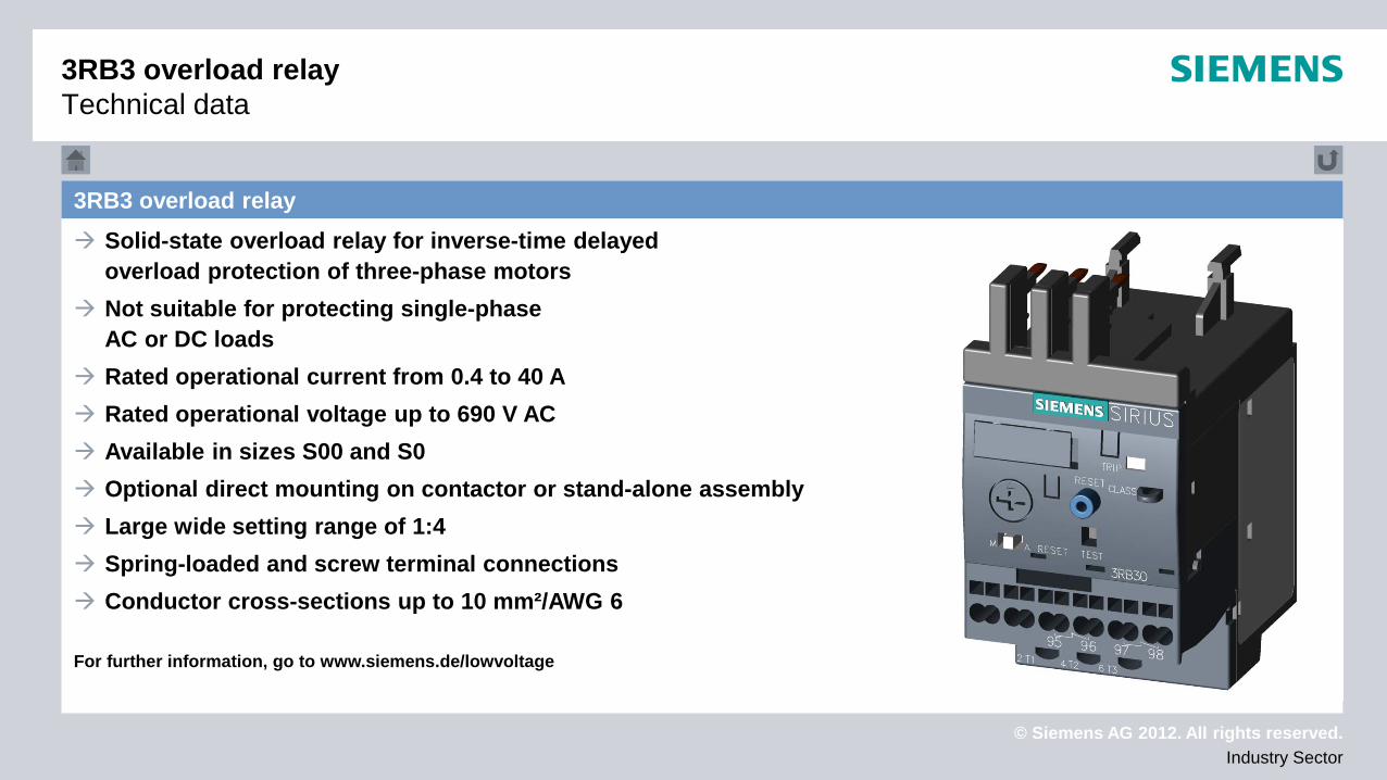
3RB3 overload relay Solid-state overload relay for inverse-time delayed
overload protection of three-phase motors Not suitable for protecting single-phase
AC or DC loads Rated operational current from 0.4 to 40 A Rated operational voltage up to 690 V AC Available in sizes S00 and S0 Optional direct mounting on contactor or stand-alone assembly Large wide setting range of 1:4 Spring-loaded and screw terminal connections Conductor cross-sections up to 10 mm²/AWG 6 For further information, go to www.siemens.de/lowvoltage
3RB3 overload relay Technical data
© Siemens AG 2012. All rights reserved. Industry Sector
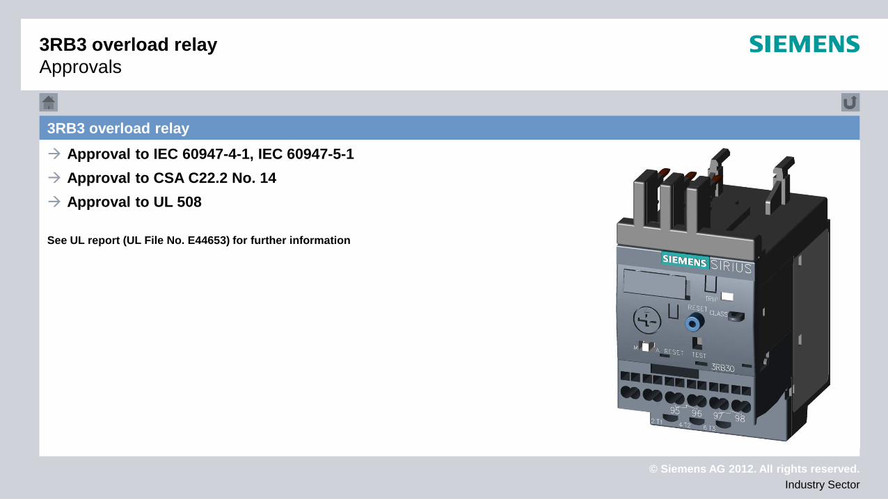
3RB3 overload relay Approval to IEC 60947-4-1, IEC 60947-5-1 Approval to CSA C22.2 No. 14 Approval to UL 508 See UL report (UL File No. E44653) for further information
3RB3 overload relay Approvals

© Siemens AG 2012. All rights reserved. Industry Sector
3RR2 monitoring relay
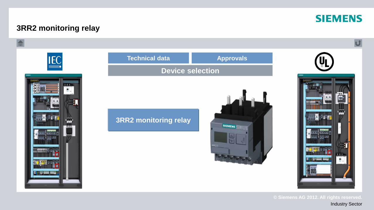
3RR2 monitoring relay
© Siemens AG 2012. All rights reserved. Industry Sector
3RR2 monitoring relay
3RR2 monitoring relay
Technical data Approvals
Device selection
© Siemens AG 2012. All rights reserved. Industry Sector
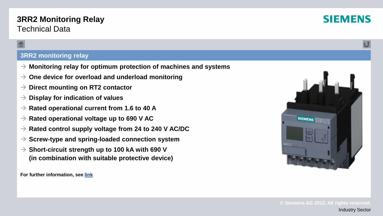
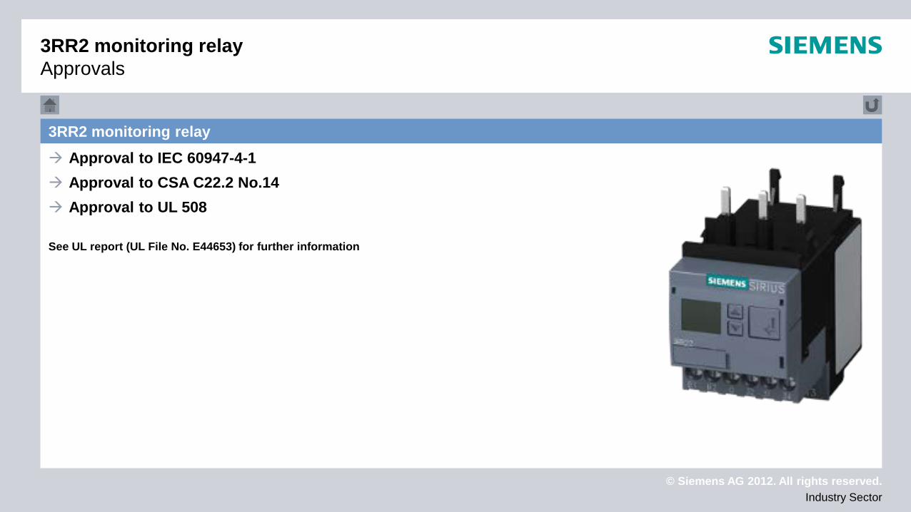
3RR2 monitoring relay Monitoring relay for optimum protection of machines and systems One device for overload and underload monitoring Direct mounting on RT2 contactor Display for indication of values Rated operational current from 1.6 to 40 A Rated operational voltage up to 690 V AC Rated control supply voltage from 24 to 240 V AC/DC Screw-type and spring-loaded connection system Short-circuit strength up to 100 kA with 690 V
(in combination with suitable protective device) For further information, see link
3RR2 Monitoring Relay Technical Data
© Siemens AG 2012. All rights reserved. Industry Sector
3RR2 monitoring relay Approvals
3RR2 monitoring relay Approval to IEC 60947-4-1 Approval to CSA C22.2 No.14 Approval to UL 508 See UL report (UL File No. E44653) for further information
© Siemens AG 2012. All rights reserved. Industry Sector
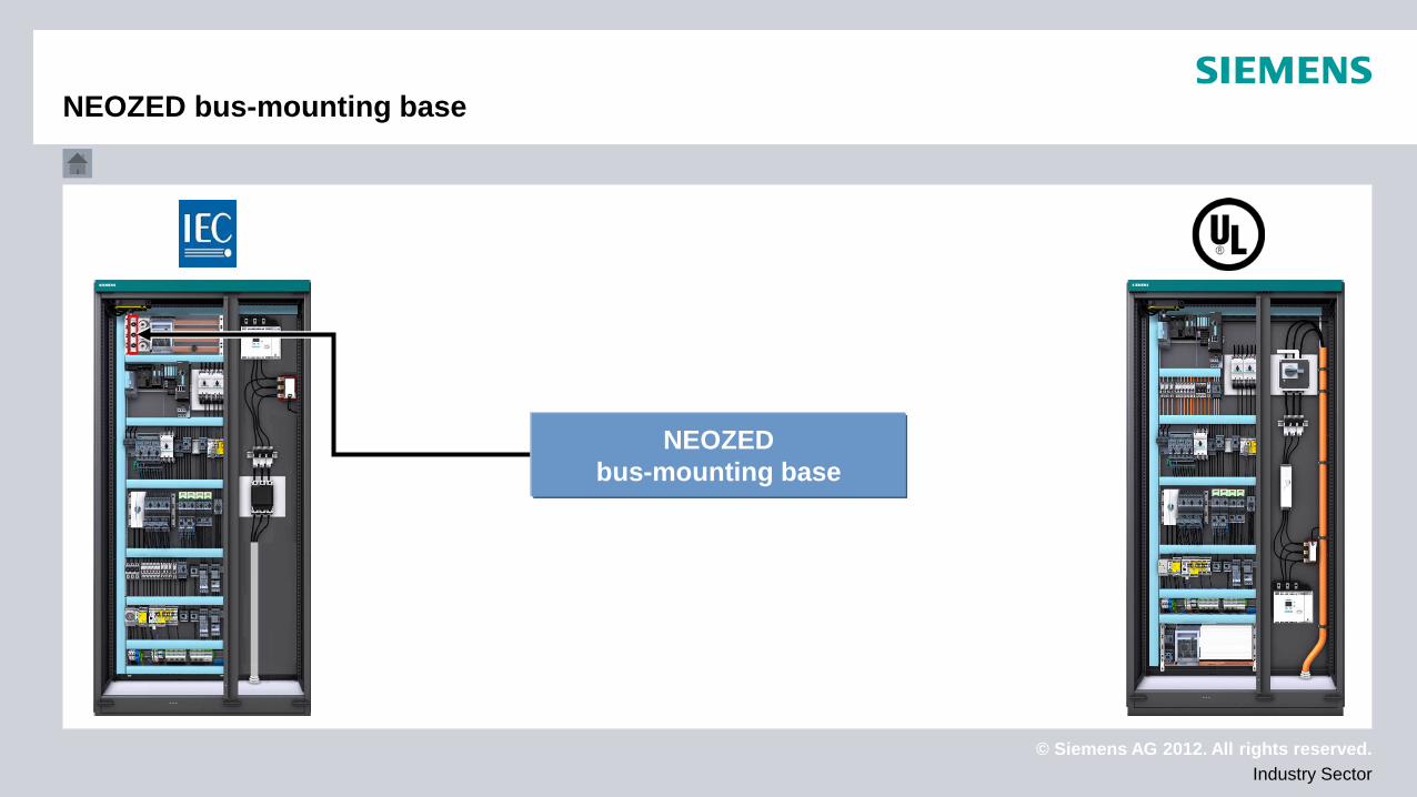
NEOZED bus-mounting base
NEOZED bus-mounting base
© Siemens AG 2012. All rights reserved. Industry Sector
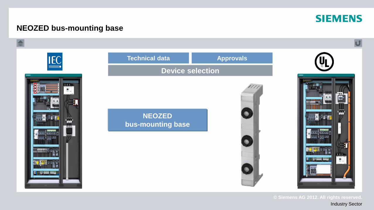
NEOZED bus-mounting base
Technical data Approvals
Device selection
NEOZED bus-mounting base
© Siemens AG 2012. All rights reserved. Industry Sector
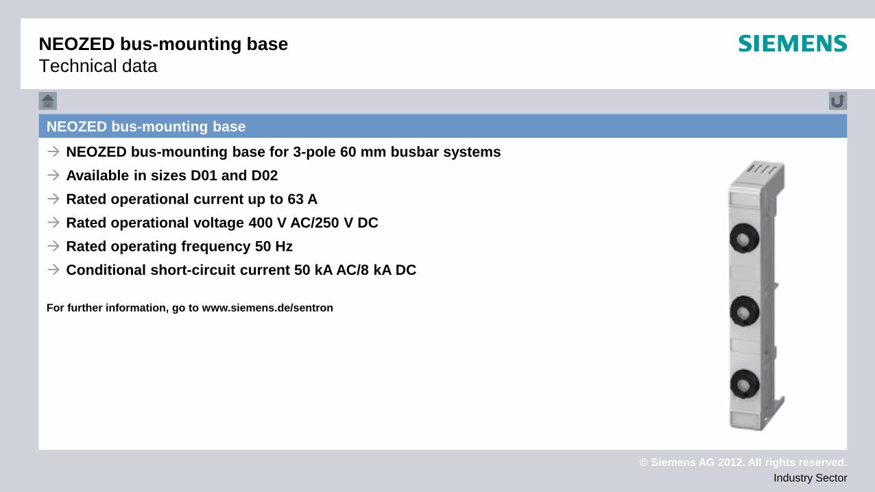
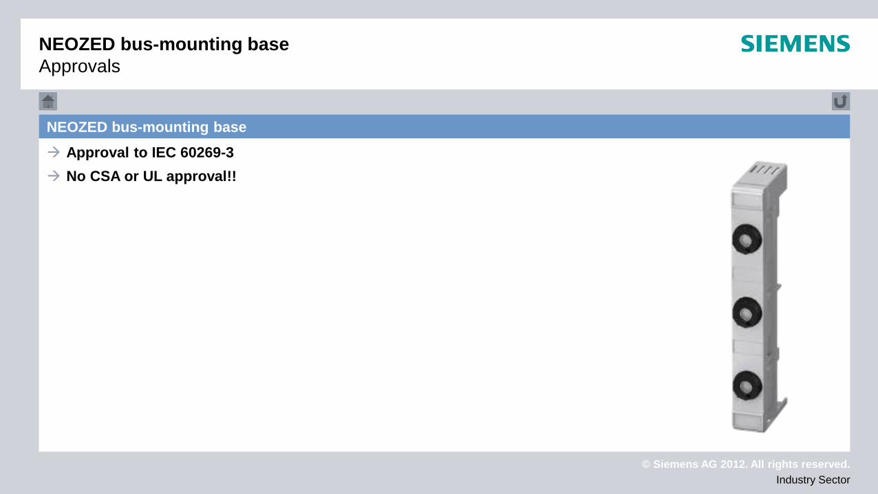
NEOZED bus-mounting base NEOZED bus-mounting base for 3-pole 60 mm busbar systems Available in sizes D01 and D02 Rated operational current up to 63 A Rated operational voltage 400 V AC/250 V DC Rated operating frequency 50 Hz Conditional short-circuit current 50 kA AC/8 kA DC For further information, go to www.siemens.de/sentron
NEOZED bus-mounting base Technical data
© Siemens AG 2012. All rights reserved. Industry Sector
NEOZED bus-mounting base Approval to IEC 60269-3 No CSA or UL approval!!
NEOZED bus-mounting base Approvals
© Siemens AG 2012. All rights reserved. Industry Sector
DIAZED bus-mounting base
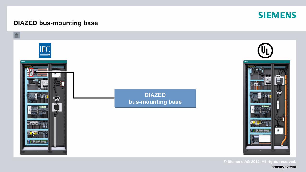
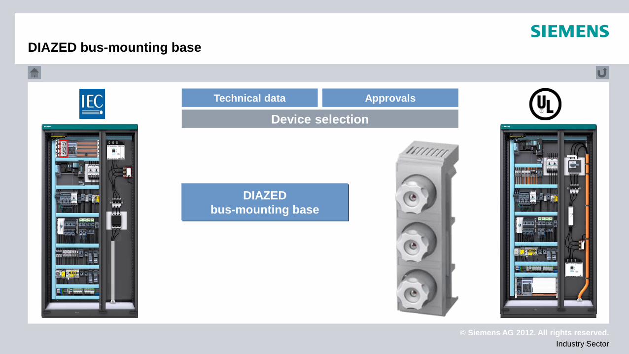
DIAZED bus-mounting base
© Siemens AG 2012. All rights reserved. Industry Sector
Technical data Approvals
Device selection
DIAZED bus-mounting base
DIAZED bus-mounting base
© Siemens AG 2012. All rights reserved. Industry Sector
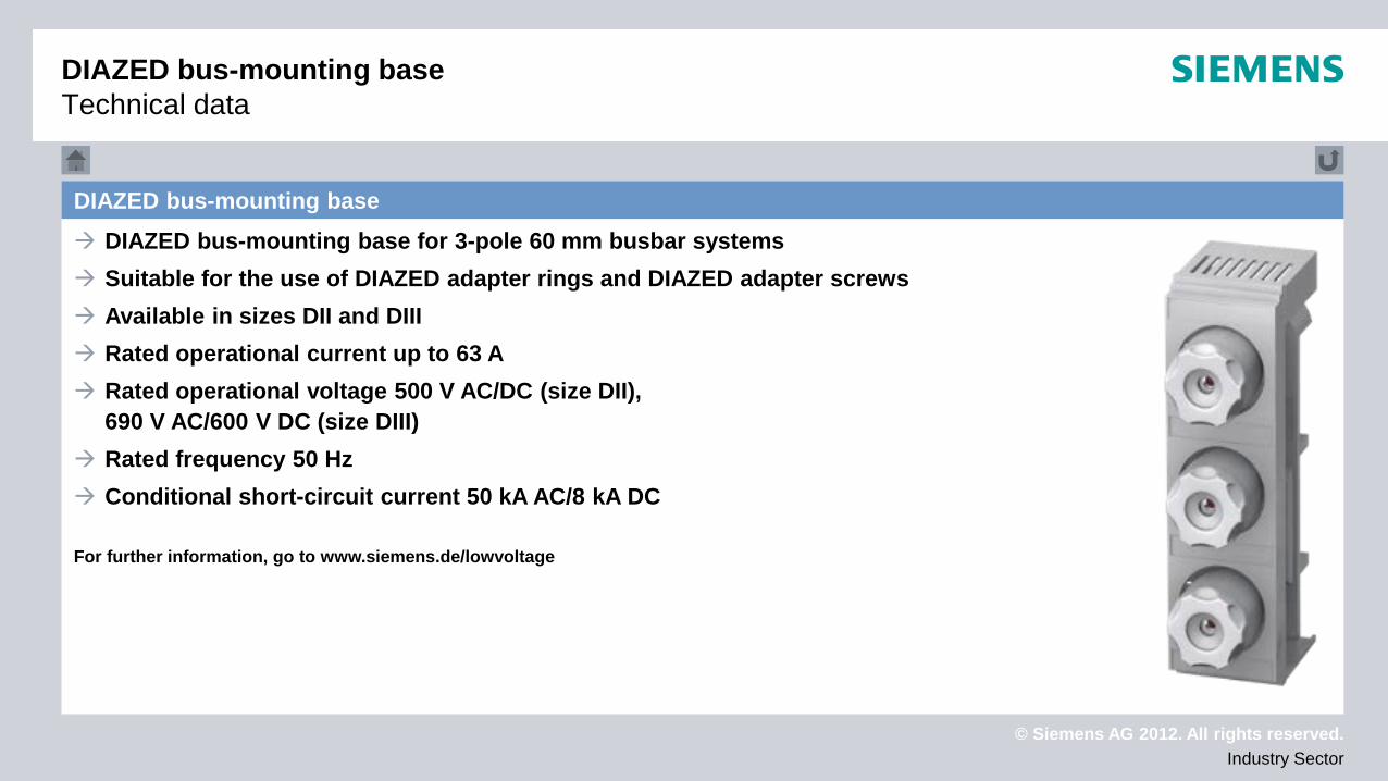
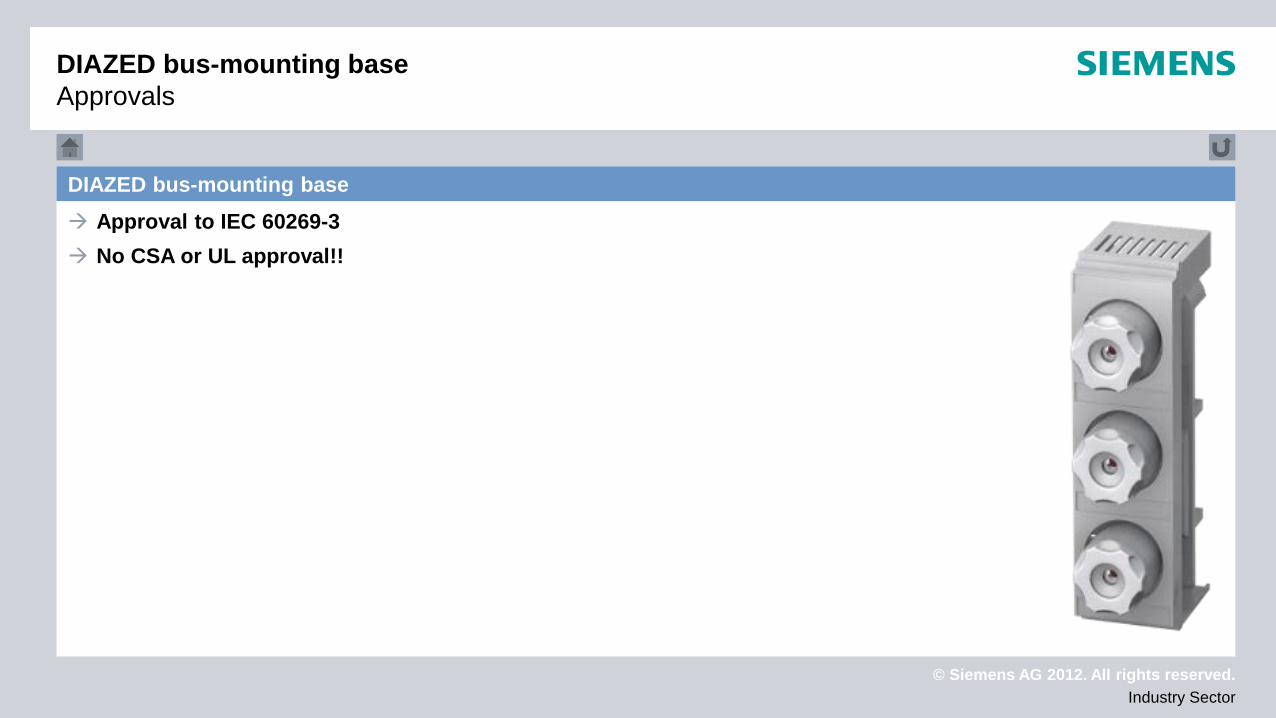
DIAZED bus-mounting base DIAZED bus-mounting base for 3-pole 60 mm busbar systems Suitable for the use of DIAZED adapter rings and DIAZED adapter screws Available in sizes DII and DIII Rated operational current up to 63 A Rated operational voltage 500 V AC/DC (size DII),
690 V AC/600 V DC (size DIII) Rated frequency 50 Hz Conditional short-circuit current 50 kA AC/8 kA DC For further information, go to www.siemens.de/lowvoltage
DIAZED bus-mounting base Technical data
© Siemens AG 2012. All rights reserved. Industry Sector
DIAZED bus-mounting base Approvals
DIAZED bus-mounting base Approval to IEC 60269-3 No CSA or UL approval!!

© Siemens AG 2012. All rights reserved. Industry Sector
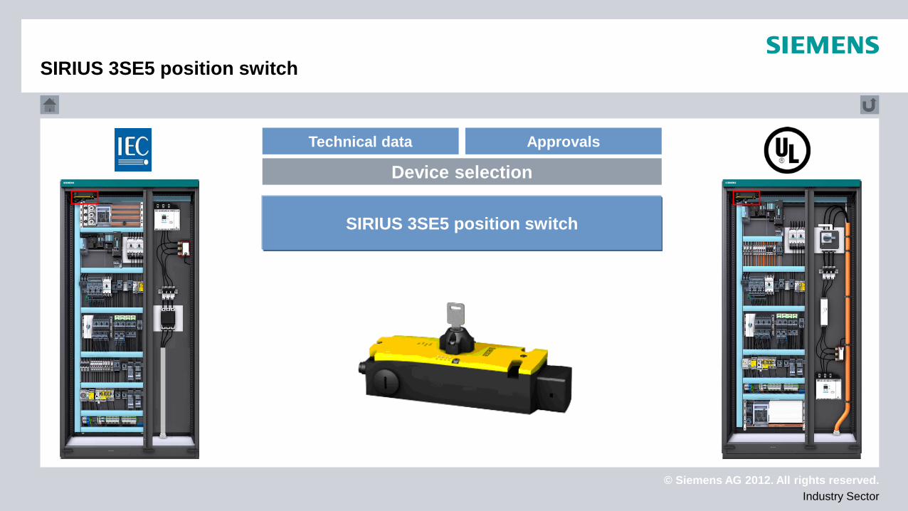
SIRIUS 3SE5 position switch
SIRIUS 3SE5 position switch
© Siemens AG 2012. All rights reserved. Industry Sector
Technical data Approvals
Device selection
SIRIUS 3SE5 position switch
SIRIUS 3SE5 position switch
© Siemens AG 2012. All rights reserved. Industry Sector
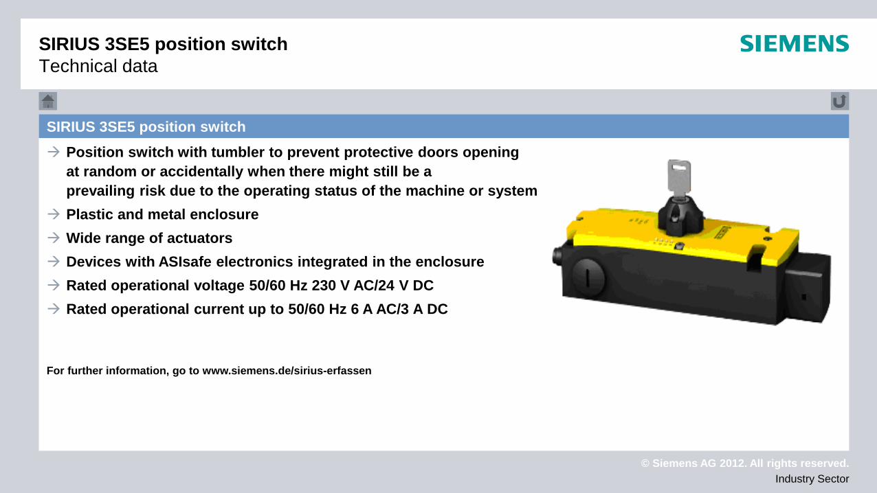
SIRIUS 3SE5 position switch Position switch with tumbler to prevent protective doors opening
at random or accidentally when there might still be a prevailing risk due to the operating status of the machine or system
Plastic and metal enclosure Wide range of actuators Devices with ASIsafe electronics integrated in the enclosure Rated operational voltage 50/60 Hz 230 V AC/24 V DC Rated operational current up to 50/60 Hz 6 A AC/3 A DC
For further information, go to www.siemens.de/sirius-erfassen
SIRIUS 3SE5 position switch Technical data
© Siemens AG 2012. All rights reserved. Industry Sector
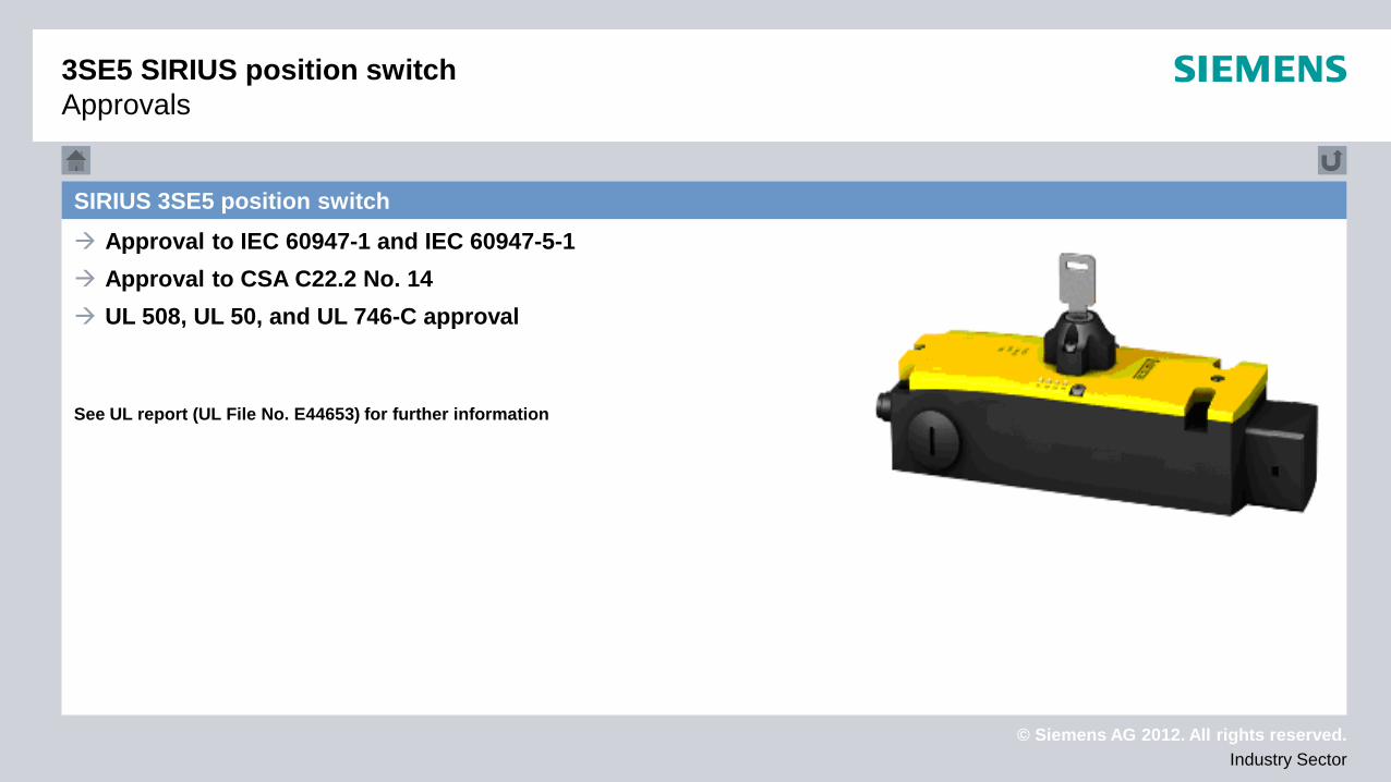
3SE5 SIRIUS position switch Approvals
SIRIUS 3SE5 position switch Approval to IEC 60947-1 and IEC 60947-5-1 Approval to CSA C22.2 No. 14 UL 508, UL 50, and UL 746-C approval
See UL report (UL File No. E44653) for further information
© Siemens AG 2012. All rights reserved. Industry Sector
SITOP power supply
SITOP power supply

© Siemens AG 2012. All rights reserved. Industry Sector
Technical data Approvals
Device selection
SITOP power supply
SITOP power supply
© Siemens AG 2012. All rights reserved. Industry Sector
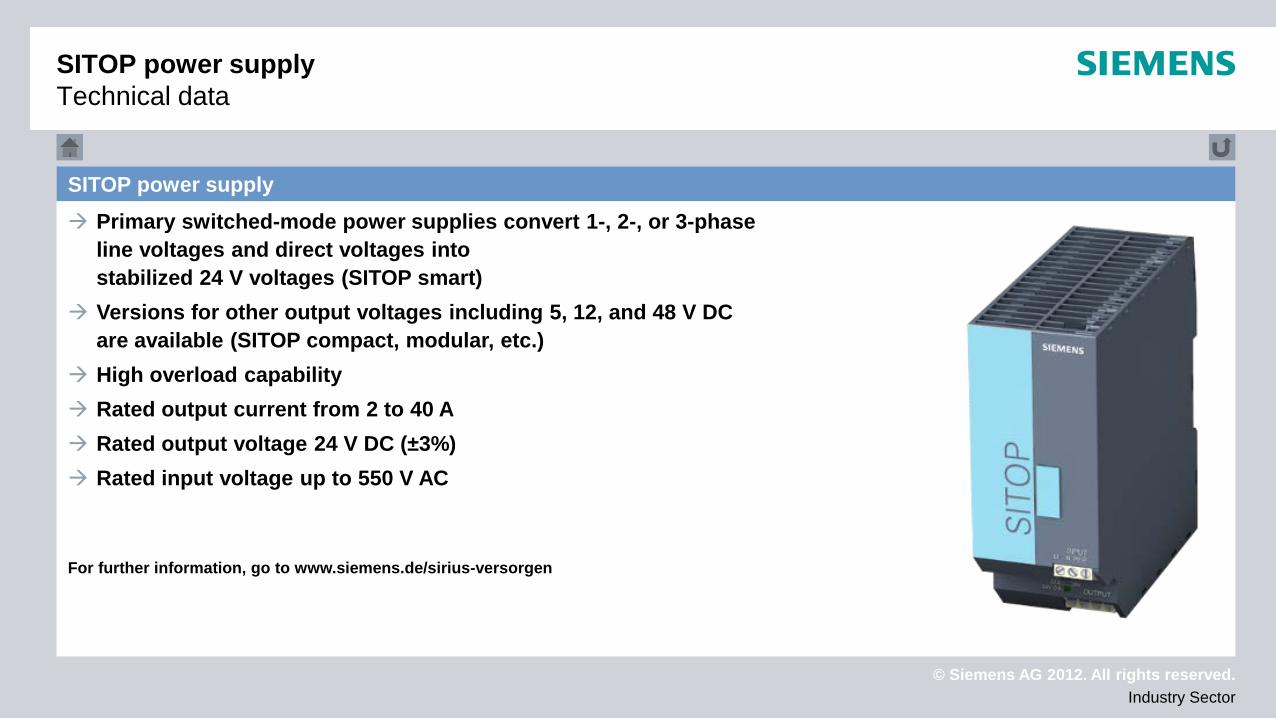
SITOP power supply Primary switched-mode power supplies convert 1-, 2-, or 3-phase
line voltages and direct voltages into stabilized 24 V voltages (SITOP smart)
Versions for other output voltages including 5, 12, and 48 V DC are available (SITOP compact, modular, etc.)
High overload capability Rated output current from 2 to 40 A Rated output voltage 24 V DC (±3%) Rated input voltage up to 550 V AC
For further information, go to www.siemens.de/sirius-versorgen
SITOP power supply Technical data
© Siemens AG 2012. All rights reserved. Industry Sector
SITOP power supply Approvals
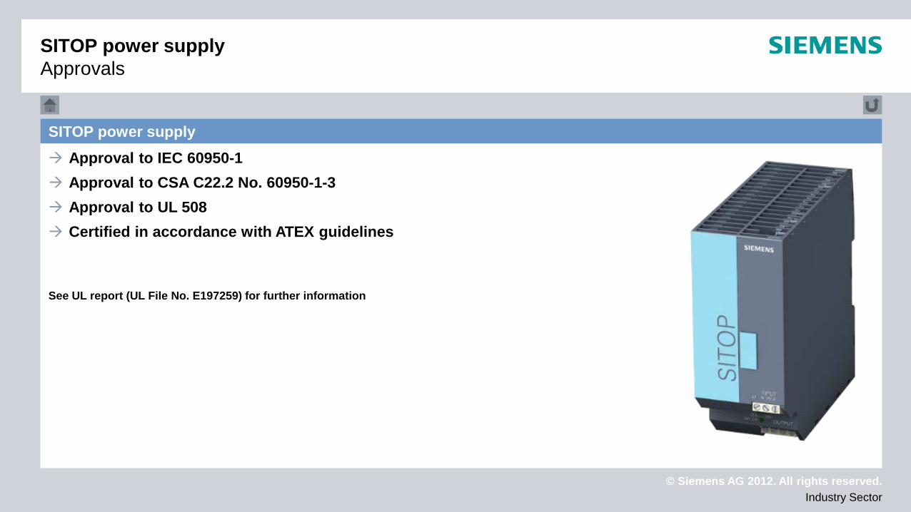
SITOP power supply Approval to IEC 60950-1 Approval to CSA C22.2 No. 60950-1-3 Approval to UL 508 Certified in accordance with ATEX guidelines
See UL report (UL File No. E197259) for further information
© Siemens AG 2012. All rights reserved. Industry Sector
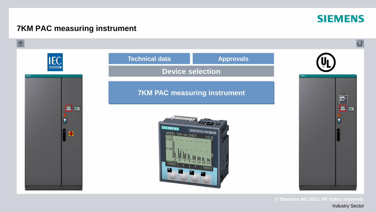
7KM PAC measuring instrument
7KM PAC measuring instrument
© Siemens AG 2012. All rights reserved. Industry Sector
Technical data Approvals
Device selection
7KM PAC measuring instrument
7KM PAC measuring instrument
© Siemens AG 2012. All rights reserved. Industry Sector
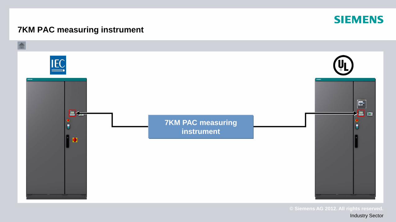
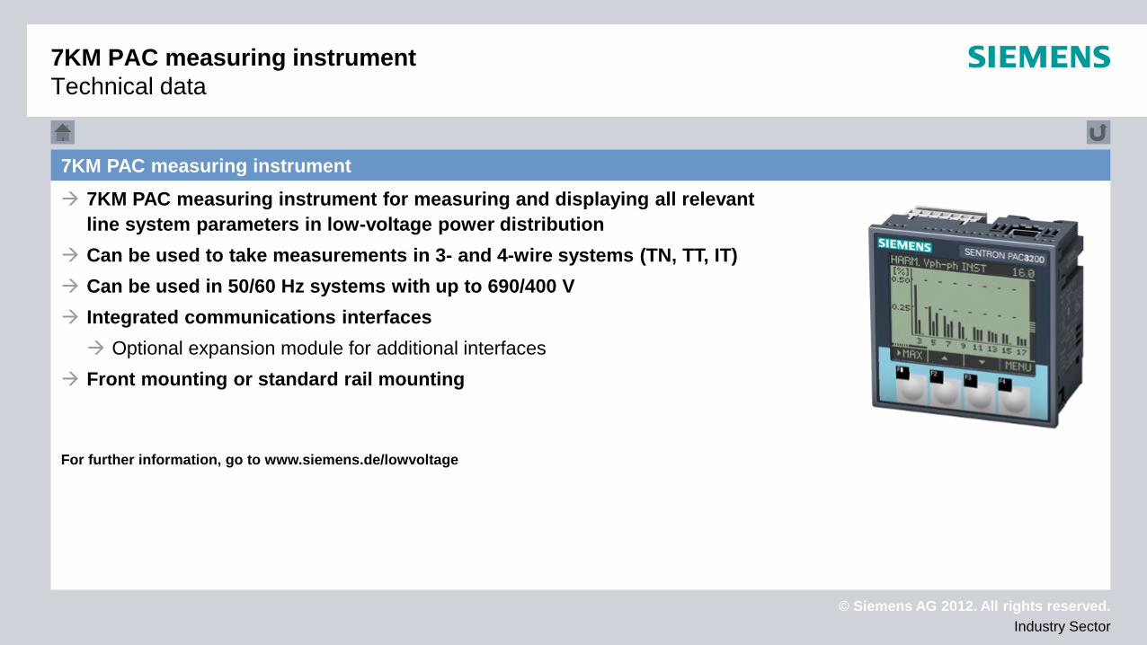
7KM PAC measuring instrument 7KM PAC measuring instrument for measuring and displaying all relevant
line system parameters in low-voltage power distribution Can be used to take measurements in 3- and 4-wire systems (TN, TT, IT) Can be used in 50/60 Hz systems with up to 690/400 V Integrated communications interfaces Optional expansion module for additional interfaces
Front mounting or standard rail mounting
For further information, go to www.siemens.de/lowvoltage
7KM PAC measuring instrument Technical data
© Siemens AG 2012. All rights reserved. Industry Sector
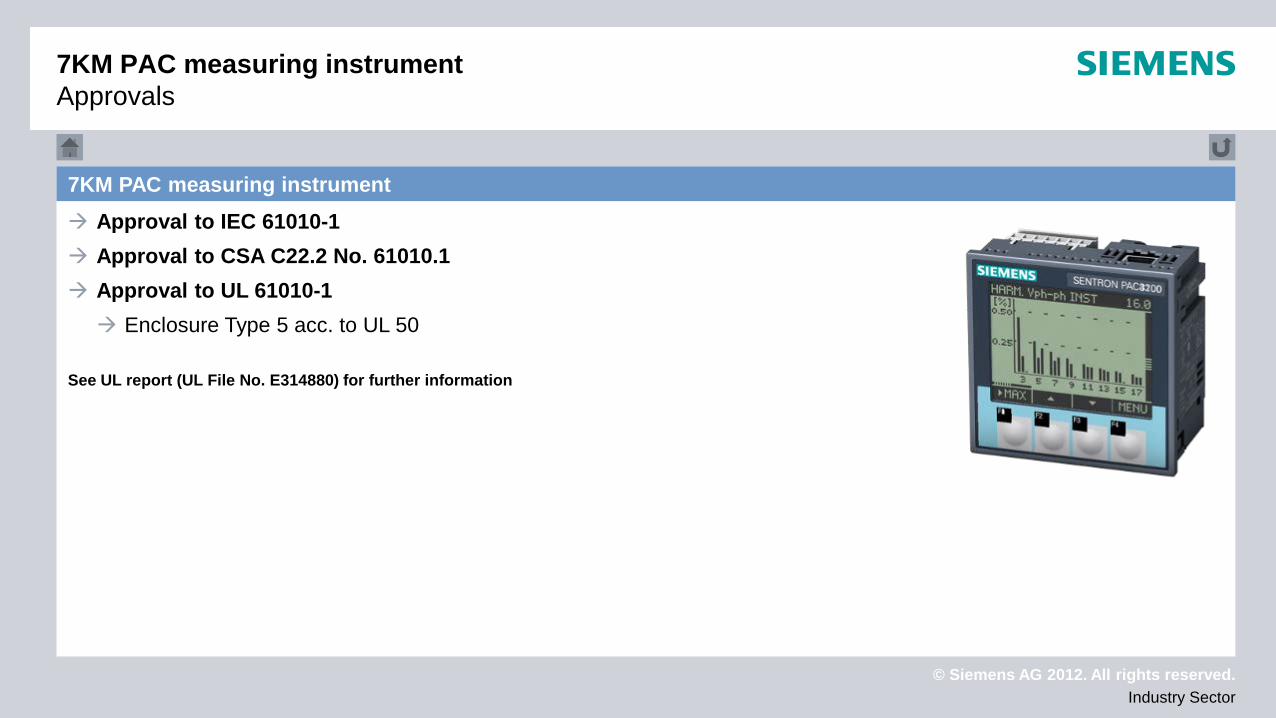
7KM PAC measuring instrument Approvals
7KM PAC measuring instrument Approval to IEC 61010-1 Approval to CSA C22.2 No. 61010.1 Approval to UL 61010-1 Enclosure Type 5 acc. to UL 50
See UL report (UL File No. E314880) for further information

© Siemens AG 2012. All rights reserved. Industry Sector
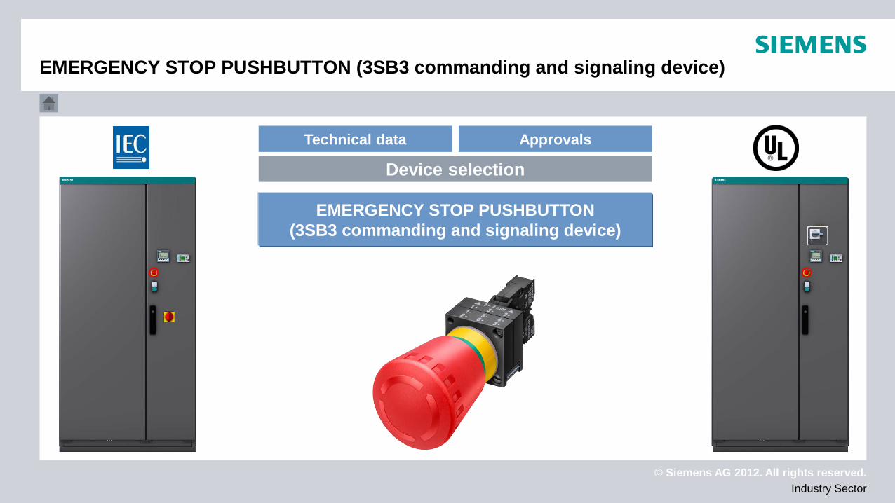
EMERGENCY STOP PUSHBUTTON (3SB3 commanding and signaling device)
EMERGENCY STOP PUSHBUTTON (3SB3 commanding and signaling device)
© Siemens AG 2012. All rights reserved. Industry Sector
Technical data Approvals
Device selection
EMERGENCY STOP PUSHBUTTON (3SB3 commanding and signaling device)
EMERGENCY STOP PUSHBUTTON (3SB3 commanding and signaling device)
© Siemens AG 2012. All rights reserved. Industry Sector
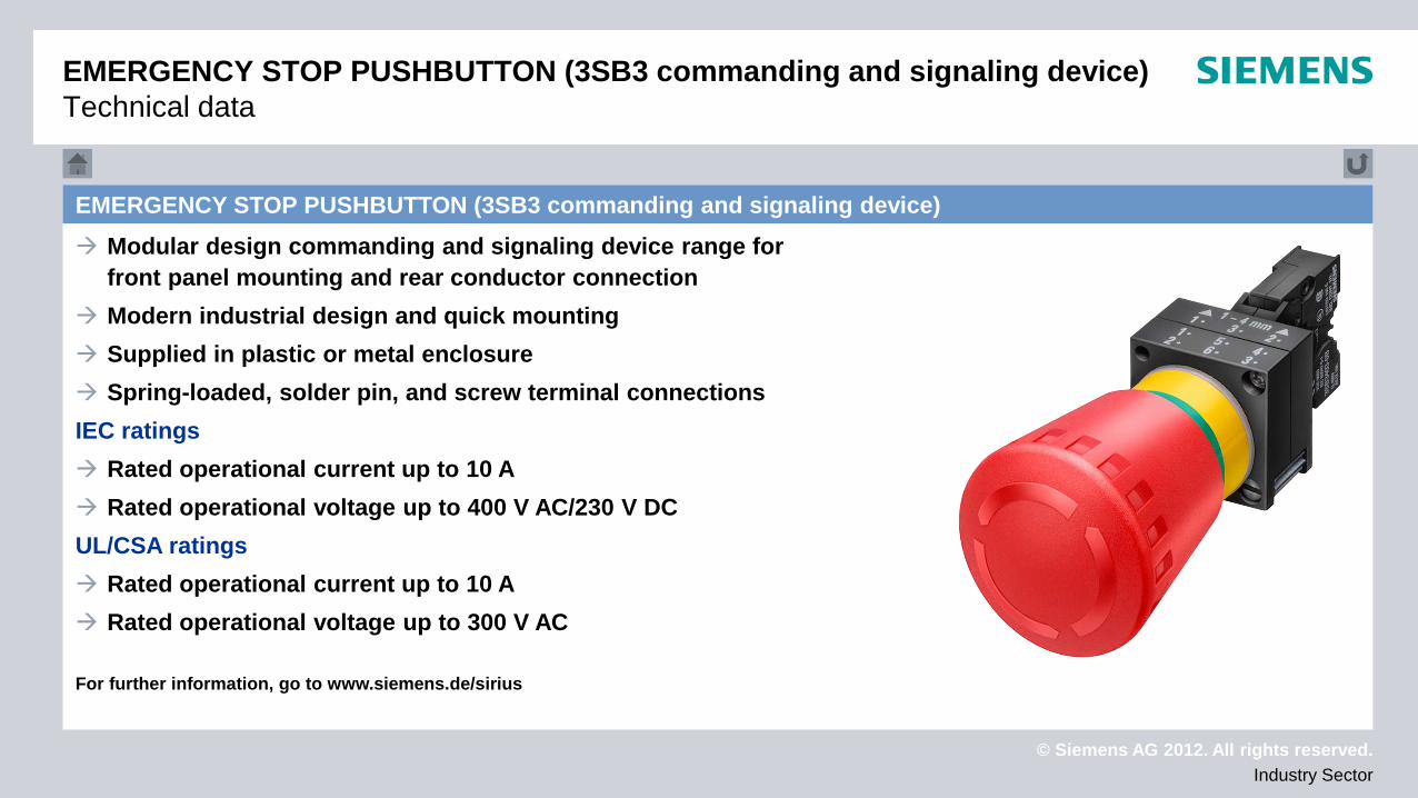
EMERGENCY STOP PUSHBUTTON (3SB3 commanding and signaling device) Modular design commanding and signaling device range for
front panel mounting and rear conductor connection Modern industrial design and quick mounting Supplied in plastic or metal enclosure Spring-loaded, solder pin, and screw terminal connections IEC ratings Rated operational current up to 10 A Rated operational voltage up to 400 V AC/230 V DC UL/CSA ratings Rated operational current up to 10 A Rated operational voltage up to 300 V AC
For further information, go to www.siemens.de/sirius
EMERGENCY STOP PUSHBUTTON (3SB3 commanding and signaling device) Technical data
© Siemens AG 2012. All rights reserved. Industry Sector
EMERGENCY STOP PUSHBUTTON (3SB3 commanding and signaling device) Approvals
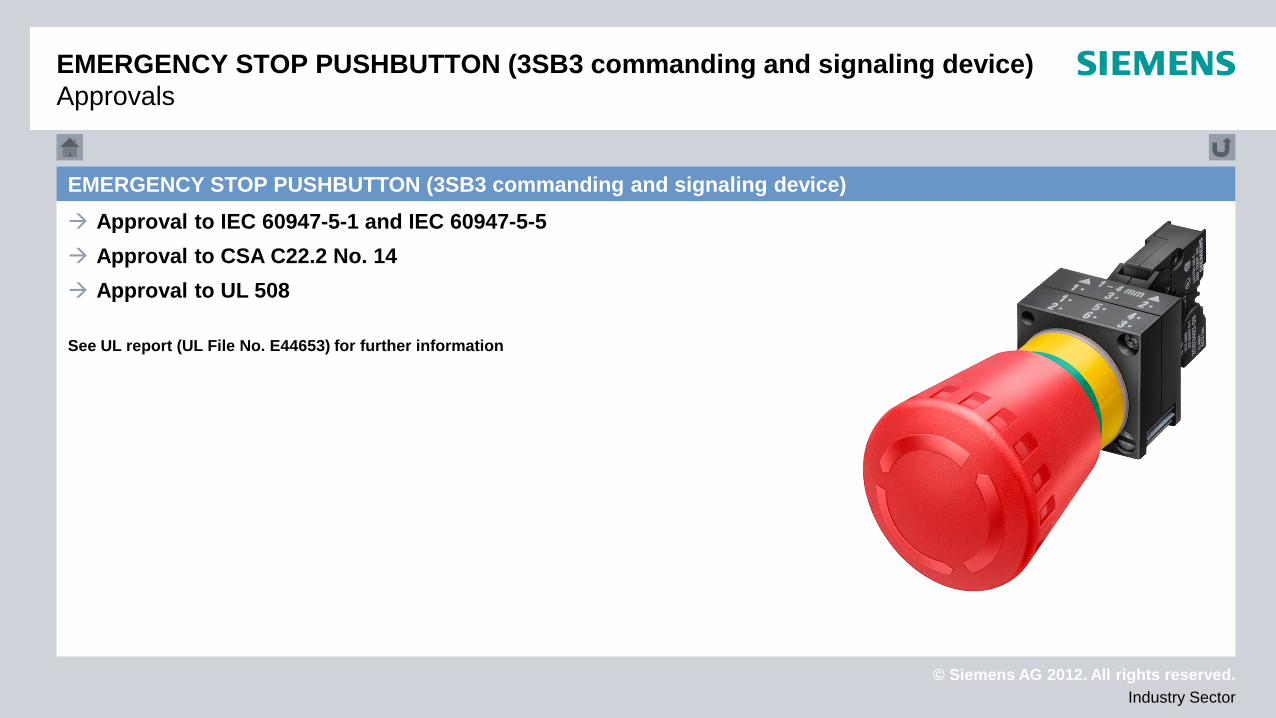
EMERGENCY STOP PUSHBUTTON (3SB3 commanding and signaling device) Approval to IEC 60947-5-1 and IEC 60947-5-5 Approval to CSA C22.2 No. 14 Approval to UL 508
See UL report (UL File No. E44653) for further information
© Siemens AG 2012. All rights reserved. Industry Sector
Main and emergency off switch
Main and emergency off switch
© Siemens AG 2012. All rights reserved. Industry Sector
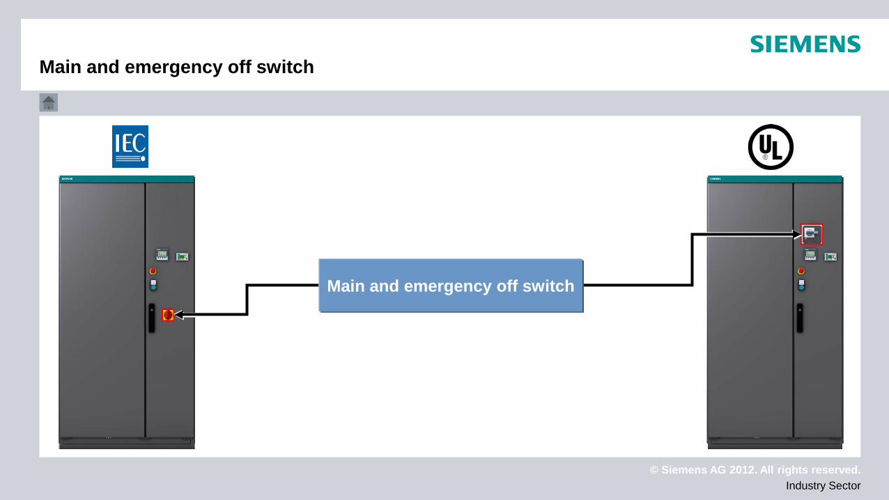
Main and emergency off switch
Main and emergency off switch
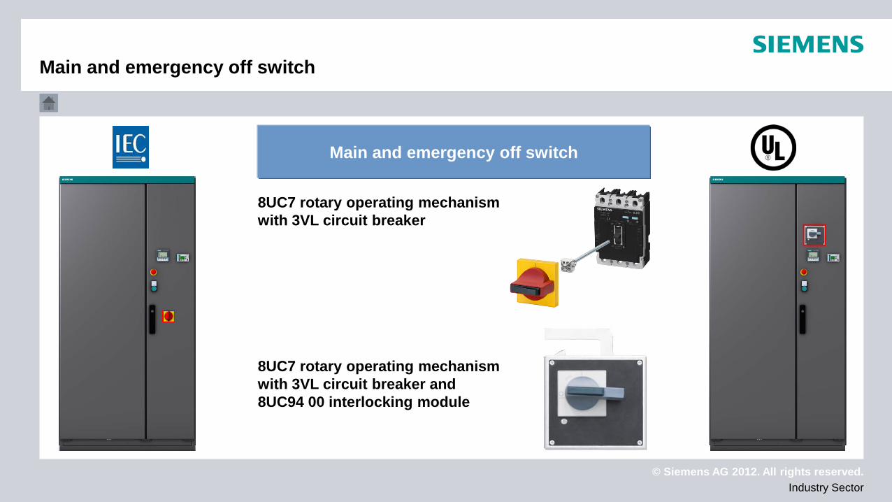
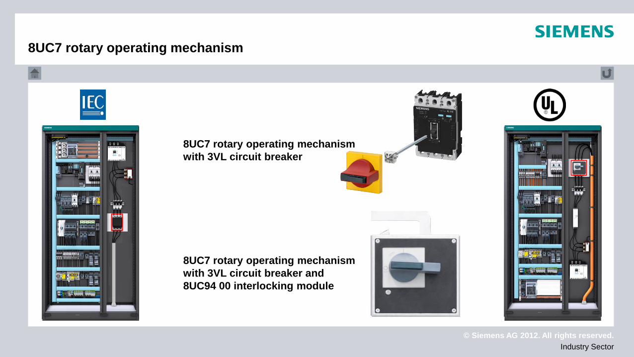
8UC7 rotary operating mechanism with 3VL circuit breaker and 8UC94 00 interlocking module
8UC7 rotary operating mechanism with 3VL circuit breaker
© Siemens AG 2012. All rights reserved. Industry Sector
Main switch (3VL circuit breaker)
Main switch (3VL circuit breaker)
© Siemens AG 2012. All rights reserved. Industry Sector
8UC7 rotary operating mechanism with 3VL circuit breaker and 8UC94 00 interlocking module
8UC7 rotary operating mechanism with 3VL circuit breaker
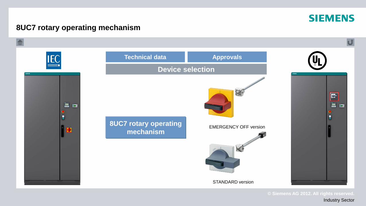
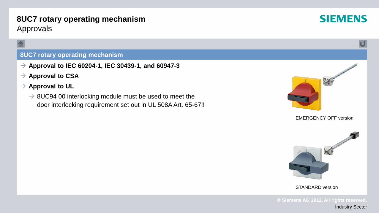
8UC7 rotary operating mechanism
© Siemens AG 2012. All rights reserved. Industry Sector
8UC7 rotary operating mechanism
Technical data Approvals
Device selection
EMERGENCY OFF version
STANDARD version
8UC7 rotary operating mechanism
© Siemens AG 2012. All rights reserved. Industry Sector
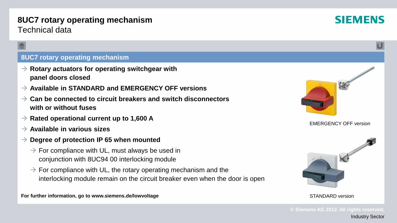
8UC7 rotary operating mechanism Technical data
8UC7 rotary operating mechanism Rotary actuators for operating switchgear with
panel doors closed Available in STANDARD and EMERGENCY OFF versions Can be connected to circuit breakers and switch disconnectors
with or without fuses Rated operational current up to 1,600 A Available in various sizes Degree of protection IP 65 when mounted For compliance with UL, must always be used in
conjunction with 8UC94 00 interlocking module For compliance with UL, the rotary operating mechanism and the
interlocking module remain on the circuit breaker even when the door is open For further information, go to www.siemens.de/lowvoltage
EMERGENCY OFF version
STANDARD version
© Siemens AG 2012. All rights reserved. Industry Sector
8UC7 rotary operating mechanism Approval to IEC 60204-1, IEC 30439-1, and 60947-3 Approval to CSA Approval to UL 8UC94 00 interlocking module must be used to meet the
door interlocking requirement set out in UL 508A Art. 65-67!!
8UC7 rotary operating mechanism Approvals
EMERGENCY OFF version
STANDARD version
© Siemens AG 2012. All rights reserved. Industry Sector
Lines/cables
Lines/cables
© Siemens AG 2012. All rights reserved. Industry Sector
Applications consulting from Siemens AG is a free-of-charge service for our customers.
Information, recommendations or instructions (hereinafter referred to as "information") from Siemens AG
are intended to assist the customer and represent descriptions of performance or performance features
of the respective products. Customers are themselves responsible for proper operation of the products within
the scope of the applicable regulations.
According to statutory regulations, Siemens AG is liable for the free-of-charge information only in the event
of intent or gross negligence. Beyond this scope, liability on the part of Siemens AG is excluded. This shall not
apply in cases where statutory liability is cogent, e.g. under the terms of product liability law.
NOTE: