1
Page 1
1
B4-130Saudi Arabia Central-West HVDC Project: 3500
MW ±600 kV LCC 770km High Performance Embedded Link Crossing a
Desert Area A.H. AL-MUBARAK*, M.Z. AL-KADHEM
Kingdom of Saudi Arabia A. AGUSTONI, A. ARDITO, A. DANELLI, S.
MALGAROTTI, I. VALADÈ CESI S.p.A. Italy
Presented byProfessor Ahdab Elmorshedy
President of the Egyptian CIGRE National Committee
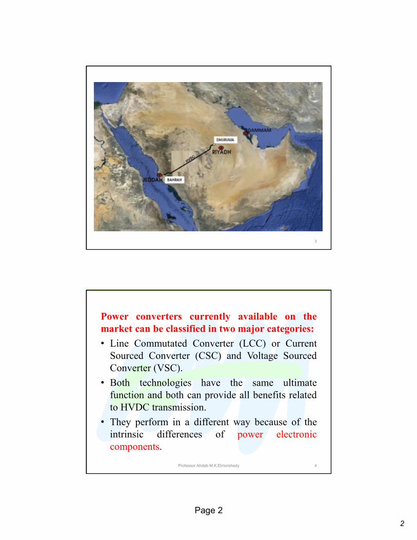
• A long distance HVDC transmission link between
Central Operating Area and Western Operating Area
in the Kingdom of Saudi Arabia was planned and
designed.
• It is currently under development.
• This 770 km long point-to-point link consists of twoLCC type converter stations.
• It is embedded in a powerful AC network.
• Both converter stations are connected to 380 kVexisting substations, each one part of a meshed
network.
2
2
Page 2
3
Power converters currently available on themarket can be classified in two major categories:
• Line Commutated Converter (LCC) or Current
Sourced Converter (CSC) and Voltage Sourced
Converter (VSC).
• Both technologies have the same ultimate
function and both can provide all benefits related
to HVDC transmission.
• They perform in a different way because of the
intrinsic differences of power electronic
components.
Professor Ahdab M.K.Elmorshedy 4
3
Page 3
5
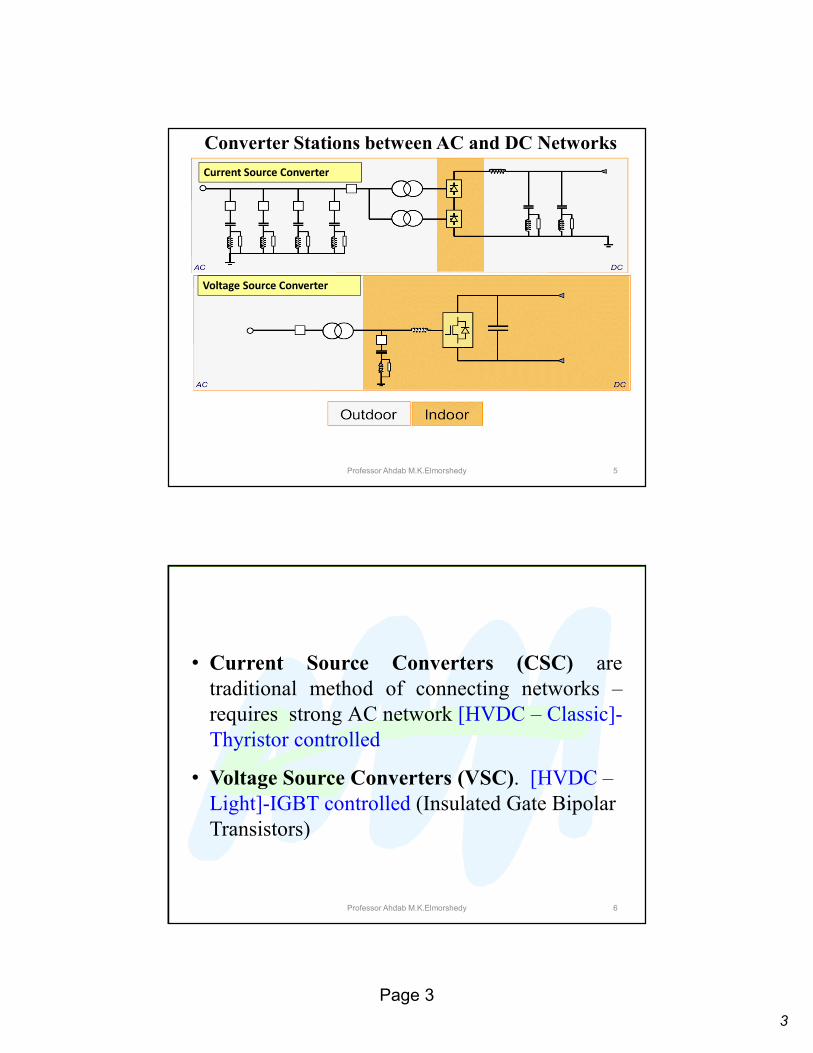
Converter Stations between AC and DC Networks
Current Source Converter
Voltage Source Converter
Professor Ahdab M.K.Elmorshedy
Professor Ahdab M.K.Elmorshedy 6
• Current Source Converters (CSC) are
traditional method of connecting networks –
requires strong AC network [HVDC – Classic]-
Thyristor controlled
• Voltage Source Converters (VSC). [HVDC –
Light]-IGBT controlled (Insulated Gate Bipolar
Transistors)
4
Page 4
The HVDC scheme is bipolar with neutraldedicated metallic return, and the possible
operating configurations are:
• normal bipolar with metallic return,
• rigid bipolar (without neutral return) and
• monopolar with different possible connections
of pole lines and metallic return.
7
• Due to environmental constraints, mainly pipelines,
no return through ground is allowed.
• The nominal voltage is ±600 kV and the nominal
power is 3500 MW with a considerable overload
capability, both in short term and in continuous
overload.
• These nominal values and the size of conductors of
the overhead line were selected on the basis of a leastcost criterion.
8

5
Page 5
• The line is fully overhead in desert area: it is a
standard HVDC tower design up to 600 kV nominal
voltage.
• The insulation withstand capability of the
transmission line and of the DC open air part of the
converter stations were selected considering the
pollution conditions, close to coastal area and in
inland area.
• The link requires a huge AC filter banks.
9
SAUDI ELECTRICITY COMPANY (SEC)
10
6
Page 6
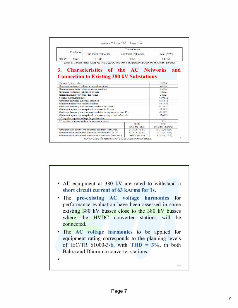
2. Selection of Nominal Power and Voltage• The losses of the converter stations versus the
transmitted power and the losses in the conductors
versus the transmitted power for a reference 35°C
ambient temperature were considered.
• The corona losses were considered as per Table 1.
• ACSR Joree (aluminum conductor steel reinforced)
11
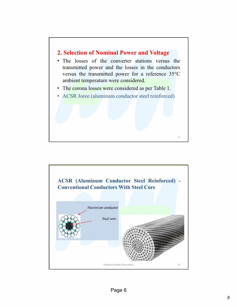
ACSR (Aluminum Conductor Steel Reinforced) -Conventional Conductors With Steel Core
Professor Ahdab Elmorshedy 12
7
Page 7
3. Characteristics of the AC Networks andConnection to Existing 380 kV Substations
13
• All equipment at 380 kV are rated to withstand a
short circuit current of 63 kArms for 1s.
• The pre-existing AC voltage harmonics for
performance evaluation have been assessed in some
existing 380 kV busses close to the 380 kV busses
where the HVDC converter stations will be
connected.
• The AC voltage harmonics to be applied for
equipment rating corresponds to the planning levels
of IEC/TR 61000-3-6, with THD = 3%, in both
Bahra and Dhuruma converter stations.
•14 /
8
Page 8
4. Environmental Conditions in the Sites ofthe Converter StationsThe environmental conditions in the sites of the two
converter stations are:
• Altitude above mean sea level: 120 m for Bahra &
655 m for Dhuruma
• Ambient air temperature (outdoor)
�minimum = -5°C
�maximum = 55°C
�monthly average of the hottest month = 45°C
�monthly average of the coldest month = -5°C
� yearly average = 35°C
15
• Maximum relative humidity = 80 ÷ 100%
• Design wind velocity = 170km/h
• Approximate highest density solar radiation =
1.10kW/m2
• Maximum earthquake severity = 0.2g
• Average rainfall per year : 330 mm
• Keraunic level: 50 storm days/year
16
9
Page 9
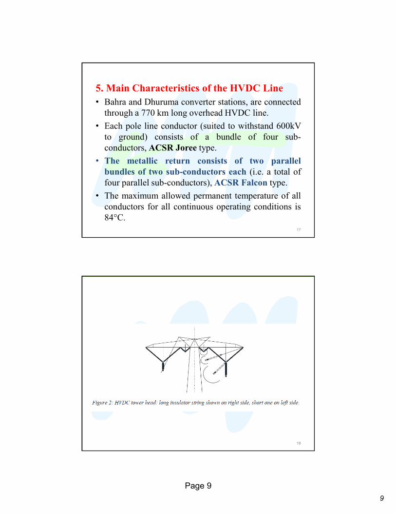
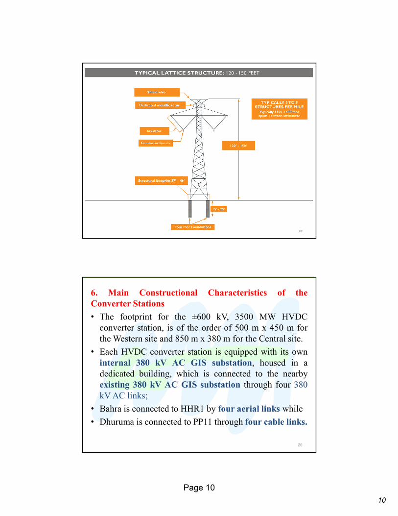
5. Main Characteristics of the HVDC Line• Bahra and Dhuruma converter stations, are connected
through a 770 km long overhead HVDC line.
• Each pole line conductor (suited to withstand 600kV
to ground) consists of a bundle of four sub-
conductors, ACSR Joree type.
• The metallic return consists of two parallelbundles of two sub-conductors each (i.e. a total of
four parallel sub-conductors), ACSR Falcon type.
• The maximum allowed permanent temperature of all
conductors for all continuous operating conditions is
84°C.
17
18
10
Page 10
19
6. Main Constructional Characteristics of theConverter Stations
• The footprint for the ±600 kV, 3500 MW HVDC
converter station, is of the order of 500 m x 450 m for
the Western site and 850 m x 380 m for the Central site.
• Each HVDC converter station is equipped with its own
internal 380 kV AC GIS substation, housed in a
dedicated building, which is connected to the nearby
existing 380 kV AC GIS substation through four 380
kV AC links;
• Bahra is connected to HHR1 by four aerial links while
• Dhuruma is connected to PP11 through four cable links.
20
11
Page 11
• The converter transformers consist of single-phaseunits and they can be either two windings or threewindings type.
• This choice has no impact on the functionalperformance of the link, but on maintenance andspare units.
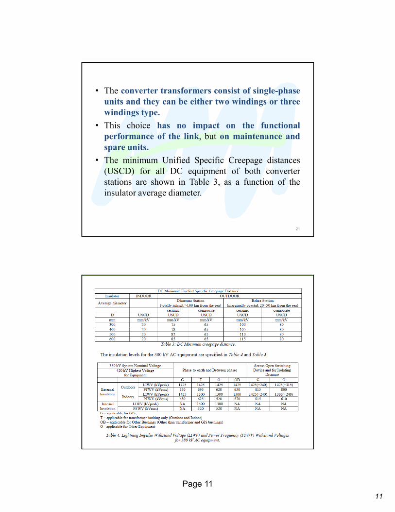
• The minimum Unified Specific Creepage distances
(USCD) for all DC equipment of both converter
stations are shown in Table 3, as a function of the
insulator average diameter.
21
22
12
Page 12
7. Main Characteristics and Performances of the HVDCLink
• The nominal capacity of the link, in both directions, is
3500 MW in bipolar configuration with a nominal DC
voltage of ±600 kV and a consequent nominal DC current
of 2917 A.
• The nominal power is delivered on the DC side of the
rectifier converter station; however the link is rated to get
3500 MW at inverter AC side.
• The valve arrangement consists of one 12-pulse converter
per pole. 23
• A dedicated metallic return is provided withoutearth electrodes.
• The DC link is operated with the neutral groundedin one converter station only, namely in Bahra.
• The insulation withstand and the rating of all
equipment and the layout of both converter stations
are suited to allow a possible future change of thegrounded converter station.
• The main operating configuration is bipolar withneutral metallic return.
24
13
Page 13
• The HVDC link will be operated for limited time inmonopolar configuration with consequent
transmission capacity reduction, due to:
� Scheduled maintenance
� Forced outages following a fault in one pole of the
converter stations or of the HVDC line
• All functional performances are referred to the
connection with the existing AC substations (point of
common coupling):
�HHR1 for Bahra converter station and
� PP11 for Dhuruma converter station.
25
• In normal bipolar operating mode the neutral isconnected to the metallic return and eachconverter pole is connected to its respective poleconductor of HVDC line (operating mode A).
• In case of outage of the metallic return, the link is
capable of operating in bipolar rigid operation with
the metallic return disconnected (operating mode D).
26
14
Page 14
• In case of any outage in one pole of either converter
station or one pole conductor of the HVDC line, thelink is capable of operating in monopolarconfiguration through a suitable DC yard
configuration.
• In case of an outage of one converter station pole, the
link can exploit both pole conductors and the metallic
return; therefore different monopolar operations are
allowed.
27
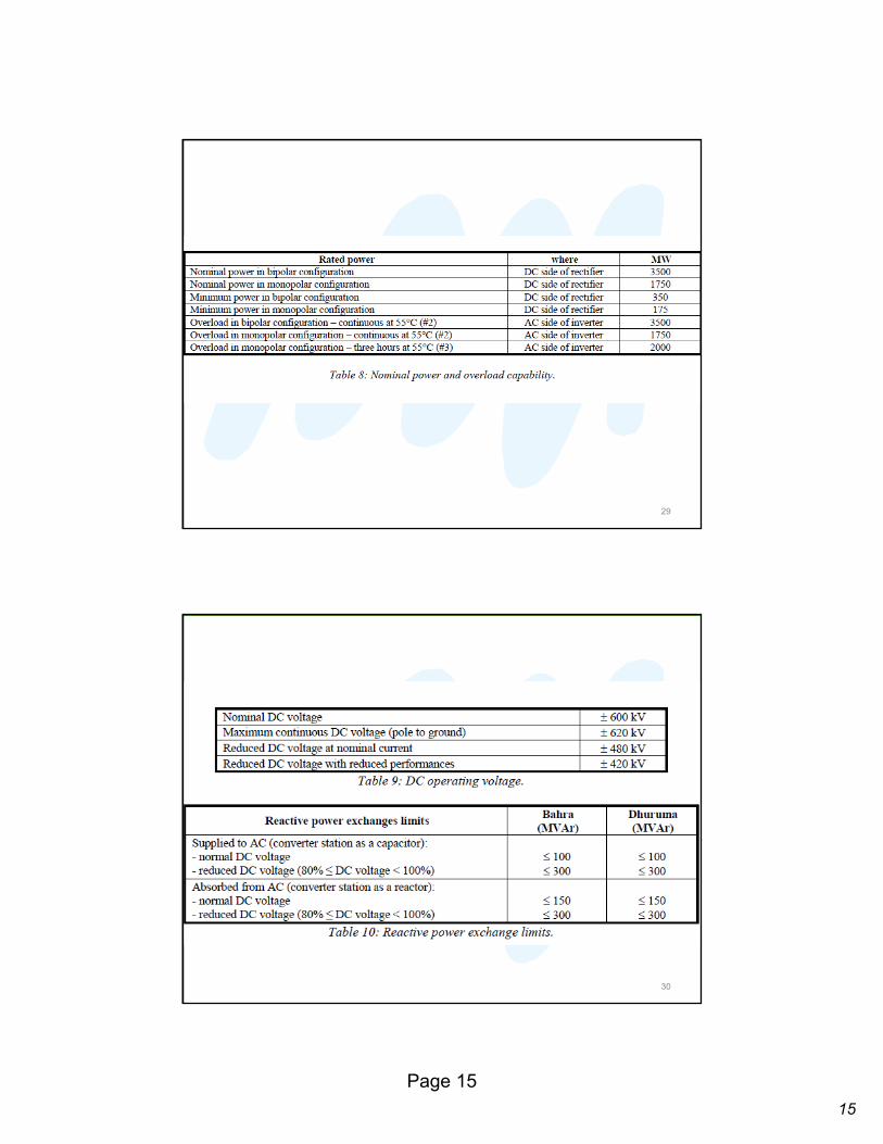
7.2 Functional performances• Table 8 summarizes the nominal power values (at DC
side of the rectifier) and the overload capability (at
AC side of the inverter, namely at existing 380 kV
AC substation).
• The link has the same transmission capability in both
directions.
• Table 9 shows the DC operating voltage values of the
link.
28
15
Page 15
29
30
16
Page 16
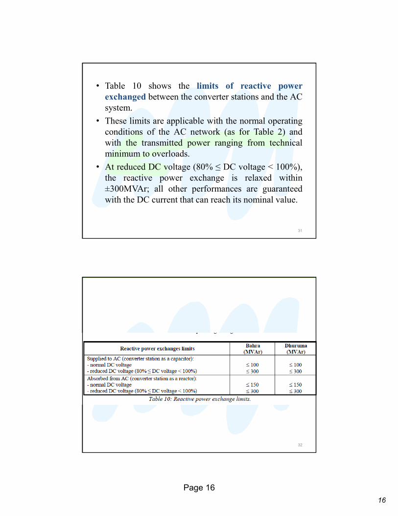
• Table 10 shows the limits of reactive powerexchanged between the converter stations and the AC
system.
• These limits are applicable with the normal operating
conditions of the AC network (as for Table 2) and
with the transmitted power ranging from technical
minimum to overloads.
• At reduced DC voltage (80% ≤ DC voltage < 100%),
the reactive power exchange is relaxed within
±300MVAr; all other performances are guaranteed
with the DC current that can reach its nominal value.
31
32
17
Page 17
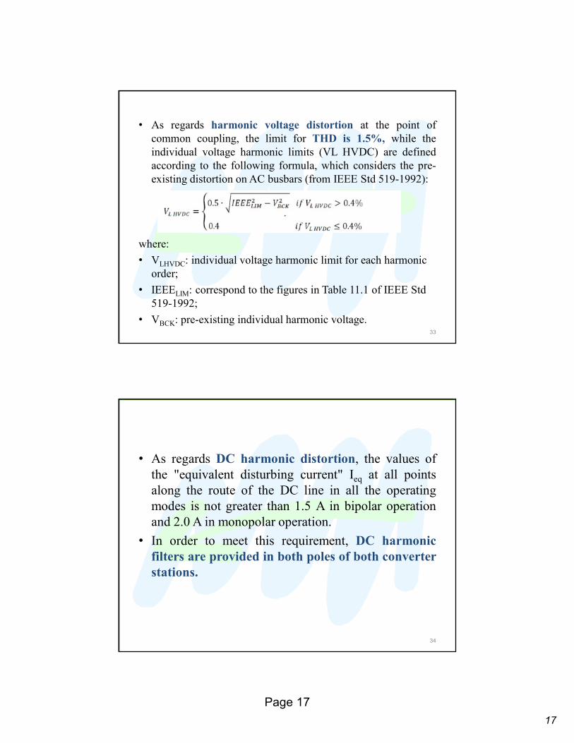
• As regards harmonic voltage distortion at the point of
common coupling, the limit for THD is 1.5%, while the
individual voltage harmonic limits (VL HVDC) are defined
according to the following formula, which considers the pre-
existing distortion on AC busbars (from IEEE Std 519-1992):
where:
• VLHVDC: individual voltage harmonic limit for each harmonic
order;
• IEEELIM: correspond to the figures in Table 11.1 of IEEE Std
519-1992;
• VBCK: pre-existing individual harmonic voltage. 33
• As regards DC harmonic distortion, the values of
the "equivalent disturbing current" Ieq at all points
along the route of the DC line in all the operating
modes is not greater than 1.5 A in bipolar operation
and 2.0 A in monopolar operation.
• In order to meet this requirement, DC harmonicfilters are provided in both poles of both converterstations.
34
18
Page 18
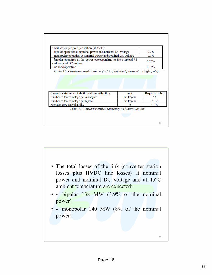
35
• The total losses of the link (converter station
losses plus HVDC line losses) at nominal
power and nominal DC voltage and at 45°C
ambient temperature are expected:
• « bipolar 138 MW (3.9% of the nominal
power)
• « monopolar 140 MW (8% of the nominal
power).
36

19
Page 19
• The power frequency component of the induced
current in the HVDC pole lines due to interaction
with parallel AC lines is kept within a tolerable value
for the converter transformer by applying suitable DC
blocking filters on the neutral side of each converter
pole.
• The whole HVDC link, both converters stations and
the overhead line, is in line with the international and
Saudi Arabia requirements for all other performance:
electric and magnetic field, audible noise,electromagnetic interference.
37
38Professor Ahdab Elmorshedy
20
Page 20
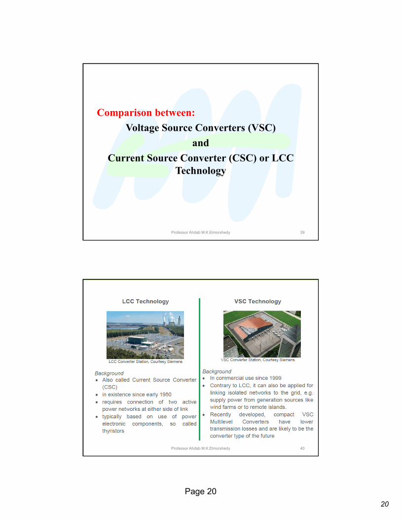
Comparison between:
Voltage Source Converters (VSC)
and
Current Source Converter (CSC) or LCC Technology
Professor Ahdab M.K.Elmorshedy 39
Professor Ahdab M.K.Elmorshedy 40
21
Page 21
Professor Ahdab M.K.Elmorshedy 41
42
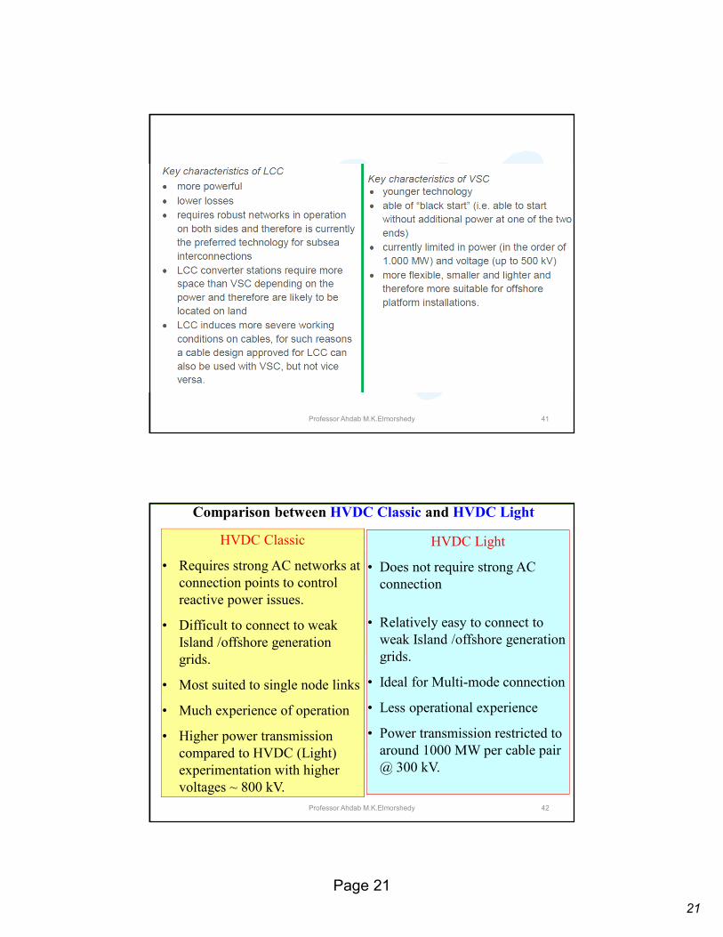
Comparison between HVDC Classic and HVDC Light
HVDC Classic
• Requires strong AC networks at
connection points to control
reactive power issues.
• Difficult to connect to weak
Island /offshore generation
grids.
• Most suited to single node links
• Much experience of operation
• Higher power transmission
compared to HVDC (Light)
experimentation with higher
voltages ~ 800 kV.
HVDC Light
• Does not require strong AC
connection
• Relatively easy to connect to
weak Island /offshore generation
grids.
• Ideal for Multi-mode connection
• Less operational experience
• Power transmission restricted to
around 1000 MW per cable pair
@ 300 kV.
Professor Ahdab M.K.Elmorshedy

22
Page 22
Weak electric grid:
• low short circuit capacity
• low x/r ratio for the feeders
• distribution networks with low voltage are
weak grid
Professor Ahdab M.K.Elmorshedy 43
Current Source Converters (CSC) and Voltage SourceConverters (VSC)
• The main requirement in a power transmission system is
the precise control of active and reactive power flow to
maintain the system voltage stability.
• This is achieved through an electronic converter and its
ability of converting electrical energy from AC to DC or
vice versa.
• There are basically two configuration types of three-
phase converters possible for this conversion process,
Current Source Converters (CSC) and Voltage Source
Converters (VSC).
• Modern HVDC transmission systems can utilize either
traditional CSC or VSC as the basic conversion
workhorse.44
23
Page 23
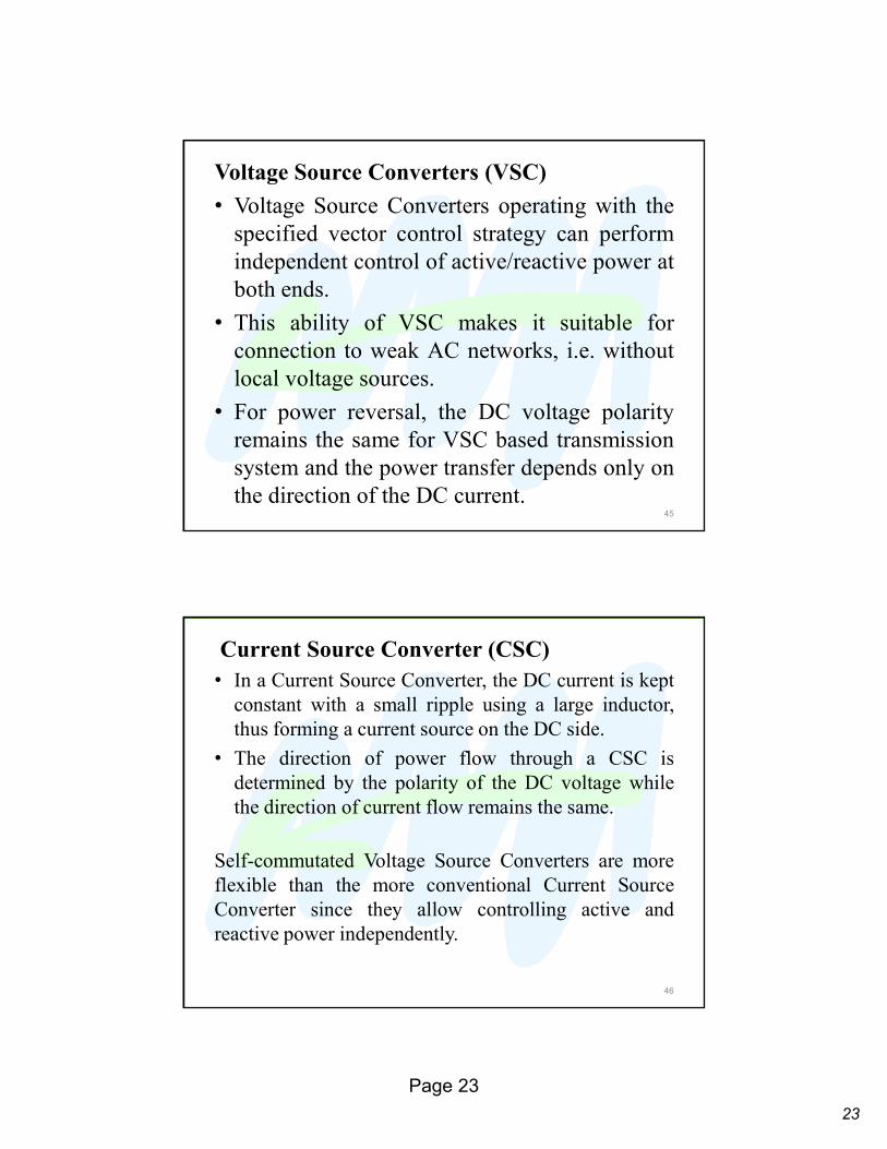
Voltage Source Converters (VSC)
• Voltage Source Converters operating with the
specified vector control strategy can perform
independent control of active/reactive power at
both ends.
• This ability of VSC makes it suitable for
connection to weak AC networks, i.e. without
local voltage sources.
• For power reversal, the DC voltage polarity
remains the same for VSC based transmission
system and the power transfer depends only on
the direction of the DC current.45
Current Source Converter (CSC)• In a Current Source Converter, the DC current is kept
constant with a small ripple using a large inductor,
thus forming a current source on the DC side.
• The direction of power flow through a CSC is
determined by the polarity of the DC voltage while
the direction of current flow remains the same.
Self-commutated Voltage Source Converters are more
flexible than the more conventional Current Source
Converter since they allow controlling active and
reactive power independently.
46