SAM-Brachytherapy II:
Integrating Imaging with HDR
Imaging with limited or no
access to MRI
Oana Craciunescu, PhD, DABR
Department of Radiation Oncology
Duke University Medical Center
2014 AAPM – Austin, TX

Conflict of Interest
Nothing to disclose
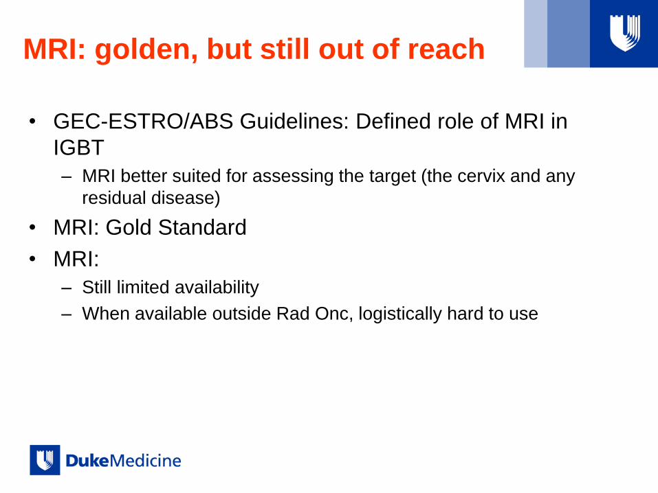
MRI: golden, but still out of reach
• GEC-ESTRO/ABS Guidelines: Defined role of MRI in
IGBT
– MRI better suited for assessing the target (the cervix and any
residual disease)
• MRI: Gold Standard
• MRI:
– Still limited availability
– When available outside Rad Onc, logistically hard to use

What to do when:
• Limited Access to MRI: Hybrid Methods
– MRI + CT
– MRI + CBCT
• NO access to MRI
– CT alone
– CBCT alone
– US-based

Limited Access: Hybrid Methods
• Use of MRI at least at 1st FX and identify HRCTV/IRCTV
• Continue subsequent fractions with
– CT
– CBCT
• Why MRI 1st FX?
• Is the Hybrid Flow an acceptable alternative to MRI for
each FX?
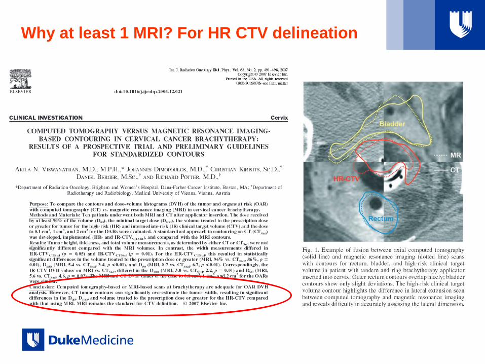
Why at least 1 MRI? For HR CTV delineation

MRI +
CT
Hybrid

Duke: Role of MRI for each fraction
• The HRCTV volumes displayed variability between fractions (median 47%
@planning, 33%), and resulted in variability in the plans developed to meet GEC-
ESTRO dose goals.
• Use MRI for each FX
J. Chino, J. Maurer, B. Steffey, J. Cai, J. Adamson, O. Craciunescu, “IS AN MRI
REQUIRED ON EACH FRACTION? AN EXPERIENCE WITH MRI GUIDED
BRACHYTHERAPY FOR CERVICAL CANCER”, World Congress of Brachytherapy,
Barcelona 2012, S107.
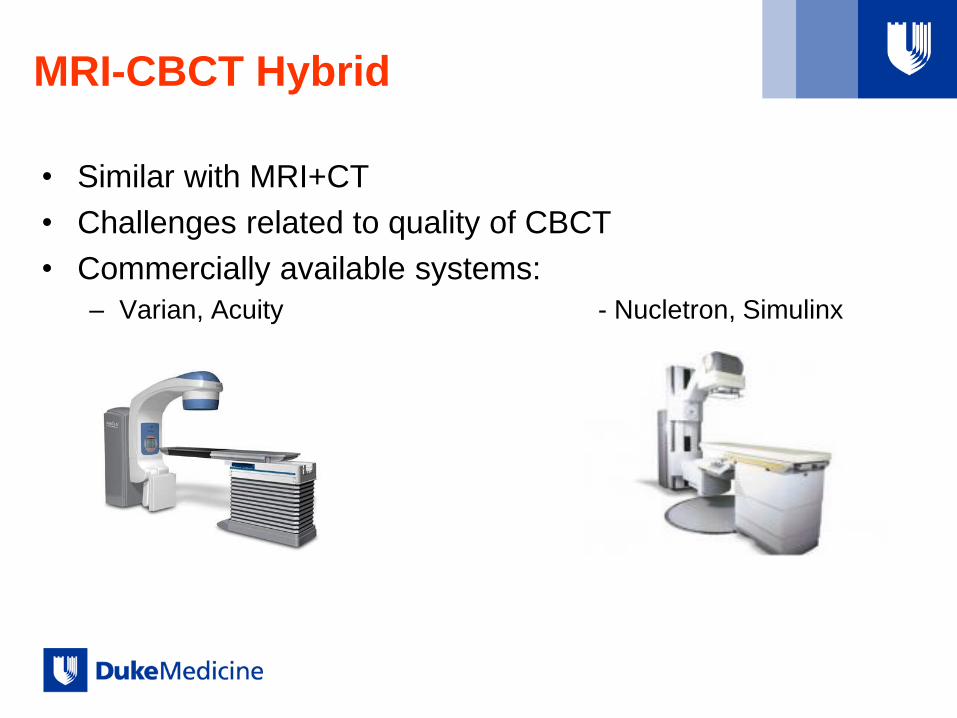
MRI-CBCT Hybrid
• Similar with MRI+CT
• Challenges related to quality of CBCT
• Commercially available systems:
– Varian, Acuity - Nucletron, Simulinx

Basic Principle
• Regular CT vs. CBCT: acquisition
Regular CT: fan-beam
line-detector
multiple-rotations
CBCT: cone-beam
flat panel-detector
one-rotation
Image Courtesy of M. Simon and C. Sauerwein via You Zhang

Limitations vs. CT
• Regular CT vs. CBCT: image quality
CT CBCT
CT CBCT
More noise, lower SNR, and less
accurate HU number for CBCT
due to more scatter in CBCT
imaging
Limited FOV and scan extent of
CBCT
Slide Courtesy of You Zhang, Fang-Fang Yin and Lei Ren

Artifacts
Ring artifact by
defective detector
elements
Metal streak
artifact
by photon
starvation
Under-sampling
aliasing Motion-induced
blurring
Beam hardening-
induced cupping
artifact
1. Ring artifact & motion induced blurring : R Schulze et al, Dentomaxillofacial Radiology 2011
2. Metal streak artifact: http://www.exxim-cc.com/metal_artifact_reduction.html
3. Beam-hardening induced cupping artifact:
http://oftankonyv.reak.bme.hu/tiki-download_file.php?fileId=434&display
Slide Courtesy of You Zhang, Fang-Fang Yin and Lei Ren

CBCT – General Imagine Quality Issues
• The imaging quality in a kV-CBCT scanner is inferior to a regular fan-beam CT
scanner due to increased photon scatter intercepted by the larger 2D
detection panel leading to reduced imaging contrast, increased cupping,
streaking artifacts, and less accurate HU.
• The spatial resolution of the CBCT scanner in the axial direction is superior to
a fan beam CT scanner, however the CT spatial resolution is adequate
enough.
• CBCT imaging is slower than most regular fan-beam CT scanners.
• Limited FOV and Sup-Inf scan extent
J. H. Siewerdsen and D. A. Jaffray, “Cone-beam computed tomography
with a flat-panel imager: Magnitude and effects of x-ray scatter,” Med.
Phys. 28, 220–231 (2001).

CBCT in Brachy
• Applicator reconstruction
• OAR segmentation (as compared to CT and/or MRI)
• Model-based dose calculations on CBCT – Calibration of the kV-CBCT scanner in terms of HU versus ρe is essential for model based dose
calculation algorithms, but not important for conventional TG43 in water calculations
– No published data yet
– “Report of the Task Group 186 on model-based dose calculation methods in brachytherapy
beyond the TG-43 formalism: Current status and recommendations for clinical implementation”,
L. Beaulieu et al, Med. Phys. 39 (10), October 2012.

Brachy Suite BrachySuite Console
• CBCT Console
•
+ Access to 1.5 T MRI in Rad Onc on
same hallway
CBCT
Console

CBCT Image Quality
• Understand the effects of scan slice thickness vs
reconstructed slice thickness on resolution and contrast in
CBCT images acquired on the Acuity.
– Image quality for soft tissue contouring
– Image quality for applicators reconstruction
• Understand artifacts
• Understand limitation due to imaging parameters and
patient size
Effects of Slice Thickness vs.
Reconstructed Slice Thickness • Resolution
– Line pair insert from the Steev phantom
– Scanned the phantom twice – once with 1mm slice thickness (chosen prior to scanning) and again with 2mm slice thickness.
– Using the “Reconstruct Existing Scan” option on the Acuity: the 2mm scan was reconstructed a second time with 1mm slice thickness
– The filter and ring artifact suppression remained at default values for the scans and reconstructions
• Contrast
– CatPhan low contrast insert
– Scanned twice – 1mm slice thickness and 2mm slice thickness
– No additional reconstructions
– Filter and ring artifact suppression at default values

Resolution: 1mm Scan 1mm Recon P
rofile
Dir
ectio
n
2mm Air
2mm Solid

Resolution: 2mm Scan 2mm Recon P
rofile
Dir
ectio
n

Resolution: 2mm Scan 1mm Recon P
rofile
Dir
ectio
n

Resolution: Profiles
-1200
-1000
-800
-600
-400
-200
0
200
0 1 2 3 4 5 6 7 8
1mmScan1mmRecon
2mmScan1mmRecon
2mmScan2mmRecon
Reconstructing the 2mm scan at 1mm recovered the full resolution of the 1mm scan

Slice thickness
1mm rec 2.5 mm
Applicator Reconstruction OAR Contouring
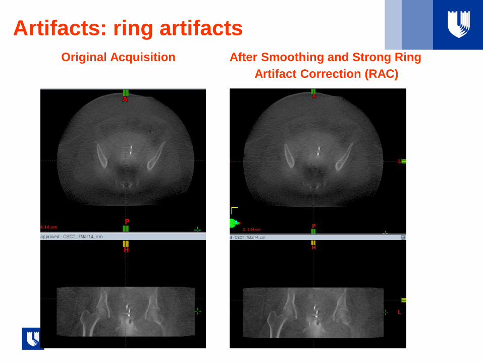
Artifacts: ring artifacts
Original Acquisition After Smoothing and Strong Ring
Artifact Correction (RAC)

Artifacts: Motion artifact

Artifacts: Bow tie filter construction Different FX, centered, patient +
offset at imaging 2.5 mm slices, smooth, Strong RAC

Artifacts: Contrast in Vaginal Balloons
20% IsoVue, 80% Saline 5% Isovue, (5% Saline)
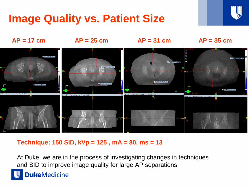
Image Quality vs. Patient Size
Technique: 150 SID, kVp = 125 , mA = 80, ms = 13
At Duke, we are in the process of investigating changes in techniques
and SID to improve image quality for large AP separations.
AP = 17 cm AP = 25 cm AP = 31 cm AP = 35 cm

CBCT vs CT
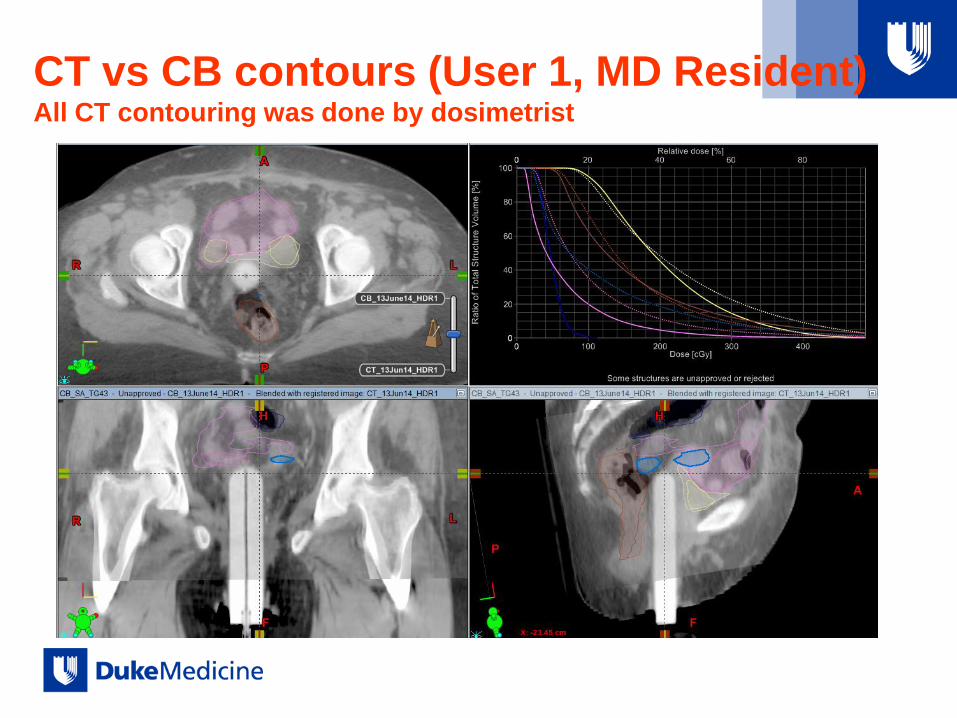
CT vs CB contours (User 1, MD Resident) All CT contouring was done by dosimetrist
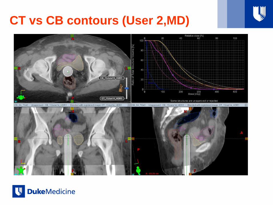
CT vs CB contours (User 2,MD)

CT vs CB contours (User 3,CMD)
Examples from Duke’s HDR GYN Practice
• FLOW (if T&R, T&O, Capri)
– US-aided applicator insertion (T&R, T&O)
– CBCT
– MRI (patient moved to MRI room)
– Planning: CBCT used for applicators, MRI for target + OARs
– CBCT right before TX
• FLOW (VBT)
– Marker insertion (FX 1 only)
– Cylinder insertion
– CBCT (planning from template done simultaneous with imaging)
– TX
– Post TX plan on CBCT: OAR contouring on CBCT
– For selected patients, CT acquired for plan and CBCT before TX

Retrospectively
• Compare CT vs CBCT contours for OARs
– Different users
• Compare dose metrics (D2cm3) for OARs between planning
image and pre-TX image
– CBCT volumes vs. CBCT volumes
– MRI volumes vs. CBCT volumes
• Establish if MRI + CBCT Hybrid (1FX MRI, subsequent
CBCT) is an acceptable alternative

Examples
Larger variations between:
1) planning and pre-TX contours
2) planning MRI and CBCT contours
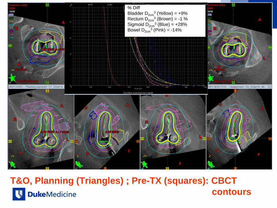
T&O, Planning (Triangles) ; Pre-TX (squares): CBCT
contours
% Diff
Bladder D2cm3 (Yellow) = +9%
Rectum D2cm3 (Brown) = -1 %
Sigmoid D2cm3 (Blue) = +28%
Bowel D2cm3 (Pink) = -14%

Planning MRI (Squares) vs Pre-TX
CBCT volumes (Triangles)
% Diff
Bladder D2cm3 (Yellow) = -37%
Rectum D2cm3 (Brown) = -1.6 %
Sigmoid D2cm3 (Blue) = -18.6%
Rectum D2cm3 (Pink) = 11.7%
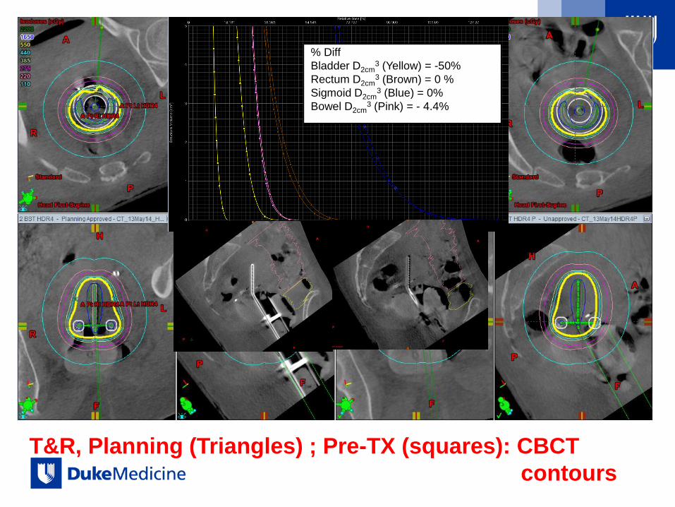
T&R, Planning (Triangles) ; Pre-TX (squares): CBCT
contours
% Diff
Bladder D2cm3 (Yellow) = -50%
Rectum D2cm3 (Brown) = 0 %
Sigmoid D2cm3 (Blue) = 0%
Bowel D2cm3 (Pink) = - 4.4%
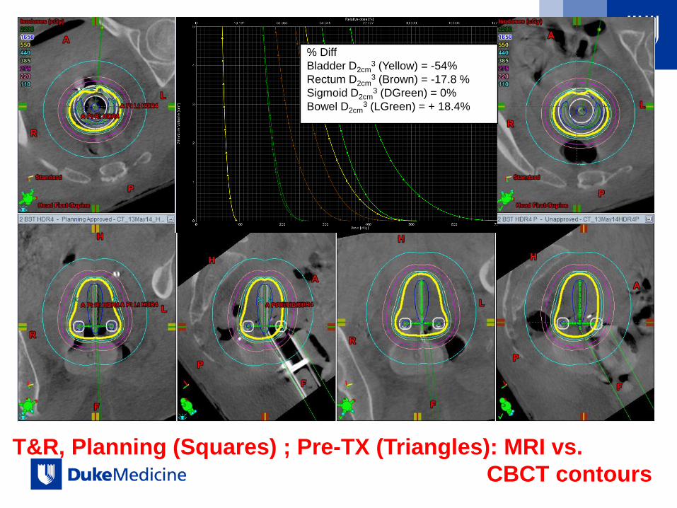
T&R, Planning (Squares) ; Pre-TX (Triangles): MRI vs.
CBCT contours
% Diff
Bladder D2cm3 (Yellow) = -54%
Rectum D2cm3 (Brown) = -17.8 %
Sigmoid D2cm3 (DGreen) = 0%
Bowel D2cm3 (LGreen) = + 18.4%

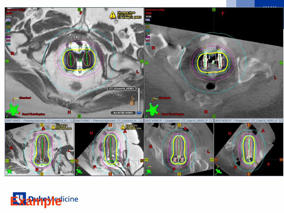
Variations in OAR contouring between
planning MRI and planning CBCT

Completely different image quality between
planning MRI and pre-TX CBCT

Example
Minimal variations between
planning(MRI) and pre-TX(CBCT)
Implicit minimal variation between
planning MRI and planning CBCT
Example
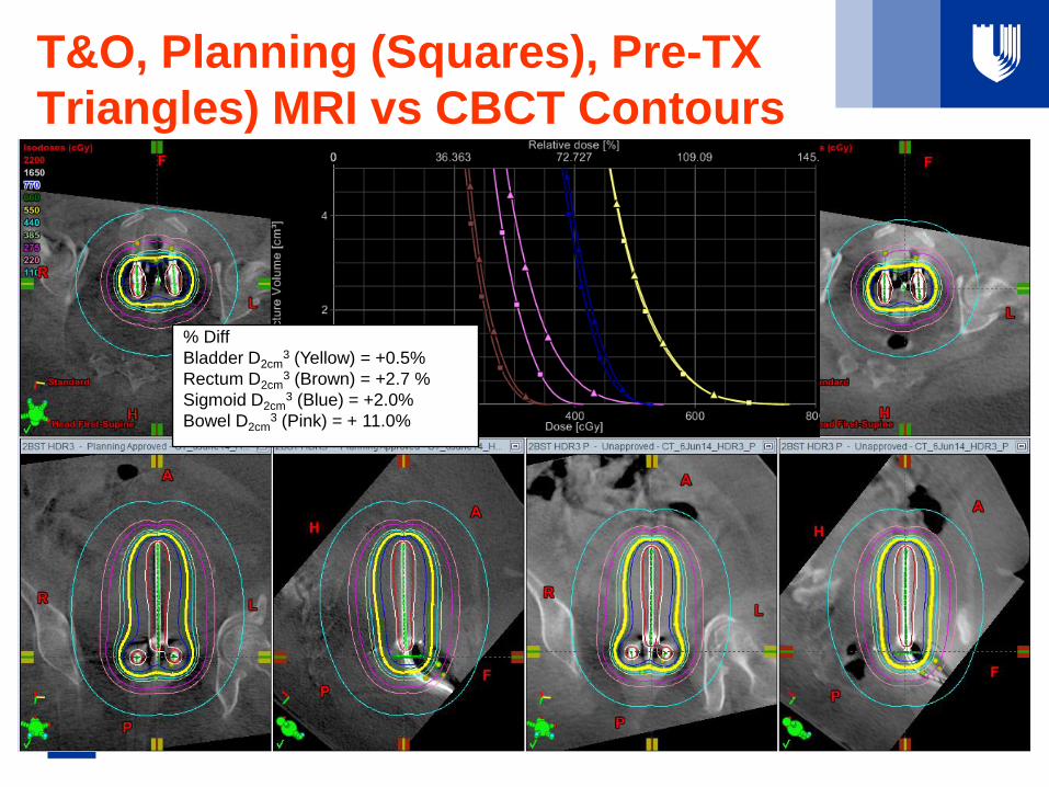
T&O, Planning (Squares), Pre-TX
Triangles) MRI vs CBCT Contours
% Diff
Bladder D2cm3 (Yellow) = +0.5%
Rectum D2cm3 (Brown) = +2.7 %
Sigmoid D2cm3 (Blue) = +2.0%
Bowel D2cm3 (Pink) = + 11.0%
What have we learned and still
learning?
• Anatomical variations in OAR between planning and Pre-
TX (3-4 hrs. later) can be large so imaging before TX is
recommended
• Potential large variations between MRI and CBCT
planning contours
• PLANNING alone – not quite there yet…attention for when
CBCT is used alone (VBT cases)
• VERIFICATION! (+ applicator rec)
What to do when:
• Limited Access to MRI: Hybrid Methods
– MRI + CT
– MRI + CBCT
• NO access to MRI
– Assume uncertainties in HR CTV delineation
– CT alone: several vs. one insertion
– CBCT alone
– US-based
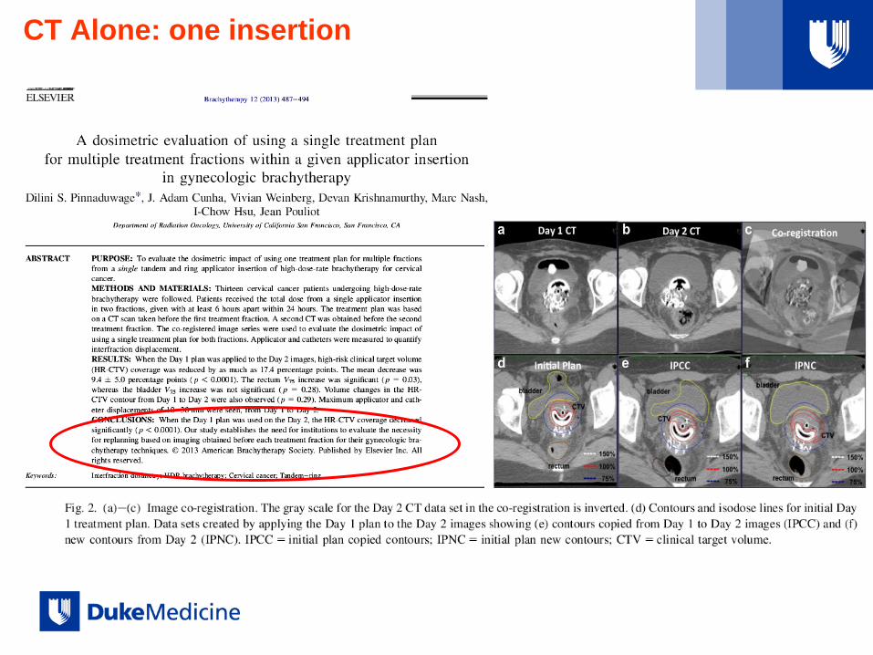
CT Alone: one insertion

CBCT Alone: CBCT for each FX

Advantage over CT (if CT not in Brachy
Suite)
• Minimize applicator motion
• Limiting the patient’s motion is expected to limit post
insertion applicator motion, which in return leads to more
accurate planning.
• No comparison with CT or MRI contours
US

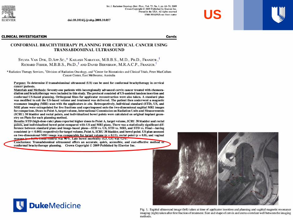
Their Conclusions (2009)
• Although lacking detailed volumetric data,
normal tissue doses can be limited through
good insertion technique and conformal
planning.
• Improvements can be made to current
treatments based on standardized 2D X-
ray image-based planning.
• US can identify an effective target volume.
• By using 2D US, it is possible to improve
technical accuracy, visualize organ
boundaries, and, with experience, plan
conformal treatments that by definition
spare OARs.
• Use of US allows for delivery of safe
treatment in a simple approach that
provides soft-tissue information not
possible with 2D X-ray imaging.

US vs.
MRI
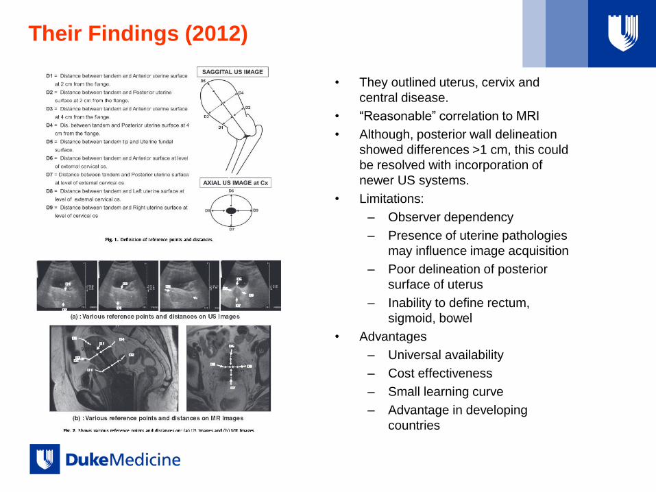
Their Findings (2012)
• They outlined uterus, cervix and
central disease.
• “Reasonable” correlation to MRI
• Although, posterior wall delineation
showed differences >1 cm, this could
be resolved with incorporation of
newer US systems.
• Limitations:
– Observer dependency
– Presence of uterine pathologies
may influence image acquisition
– Poor delineation of posterior
surface of uterus
– Inability to define rectum,
sigmoid, bowel
• Advantages
– Universal availability
– Cost effectiveness
– Small learning curve
– Advantage in developing
countries

Take Home Message: Planning with Limited
or NO MRI (GYN)
• MRI + CT/CBCT
– good solution:
– CT/CBCT(?) at planning and before TX Verification: a plus!!
• MRI (FX1)+ CT/CBCT Hybrid
– CT: good compromise solution
– CBCT: need more data to establish if appropriate for OARs
• CT/CBCT alone
– Good for applicator
– CT-good for OARs
– CBCT- need more data to establish if appropriate for OARs
– Not good for target
– Even if one insertion, departmental evaluation necessary to decide if
planning with each FX
• US
– Better then 2D X-ray imaging
– “Reasonable” correlation to MRI

Thank you!