Lehrstuhl fur Steuerungs- und Regelungstechnik
Technische Universitat Munchen
Safe and Adaptive Control Approaches forMobility Assistance Robots
Milad Geravand
Vollstandiger Abdruck der von der Fakultat fur Elektrotechnik und Informationstechnik
der Technischen Universitat Munchen zur Erlangung des akademischen Grades eines
Doktor-Ingenieurs (Dr.-Ing.)
genehmigten Dissertation.
Vorsitzender: Prof. Gordon Cheng, PhD.
Prufer der Dissertation:
1. Prof. Dr. Angelika Peer
2. Prof. Dongheui Lee, Ph.D.
Die Dissertation wurde am 29.06.2016 bei der Technischen Universitat Munchen einge-
reicht und durch die Fakultat fur Elektrotechnik und Informationstechnik am 14.11.2016
angenommen.


Foreword
This dissertation summarizes my work as a research associate at the Institute of Automatic
Control Engineering (LSR), Technische Universitat Munchen. This work was financially
supported by the MOBOT project within the 7th Framework Programme of the European
Union and the Institute for Advanced Study (IAS), Technische Universitat Munchen. I
gratefully acknowledge this generous support.
Firstly, I would like to express my sincere gratitude to my advisor Professor Angelika
Peer for her continuous support, the numerous fruitful discussions and her high research
and ethical standards. She always made plenty of time to talk about the research, was
open to possibilities, and dedicated to working through the uncertainties and difficulties
in pursuit of solutions to problems that are both challenging and practical. Her guidance
helped me throughout the research and writing of this thesis.
In addition to my advisor, I would like to thank my thesis mentor Professor Gordon
Cheng, for his insightful comments and encouragement. Moreover, my sincere thanks also
goes to Dr. Marion Leibold for her useful comments on the theories developed in the
third chapter of this thesis, Professor Alessandro De Luca for the fruitful collaboration
on the idea proposed in the sixth chapter, and Professor Martin Buss, who provided me
the opportunity to join LSR as doctoral candidate, and who gave access to the laboratory
and research facilities. Without their precious support, it would not have been possible to
conduct this research.
Many heartfelt thanks go to my great friend, and colleague, Christian Landsiedel who
always offered me assistance, whether with research or my daily life in Munich. Special
thanks go to friends and colleagues, Daniel Carton, Andreas Lawitzky, Mohammad Abu-
Alqumsan for their friendship and persistent support; Ken Friedl, for all of his positive energy,
as well as support on editing video and photos; Laith ALkurdi, Philine Donner, Stefan
Friedrich, Stefan Kersting, Alexander Pekarovskiy, Muhammad Sheraz Khan, Annemarie
Turnwald and Sotiris Apostolopoulos for all of their friendship, support, useful comments
and productive discussions. To Professor Klaus Hauer, Dr Costas Tzafestas, Professor
Petros Maragos, Professor Katja Mombaur, Dr.-Ing. Bartlomiej Stanczyk and all of
MOBOT partners for inspiring discussions and collaboration. To my students, Tobias
Blume, Wolfgang Rampeltshammeri, Andreas Lederhuber, Navid Zeinali, Erfan Shahriari,
in particular, Peter Zeno Korondi, for sharing my research interests and continually assisting
me. Finally, special thanks go to all of my other colleagues and LSR team-mate for giving
me insights, support, and friendship throughout these years. I am also very grateful to the
great administrative support I received at LSR, especially from Mrs. Schmid, who treated
me with professionalism and helped in every matter I had.
I am also grateful to the following staff at Fraunhofer IPA, Martin Hagele, Thomas Dietz,
Alexander Kuss, Julian Diaz Possada, Ulrich Schneider, for their various forms of support
during my last year of doctoral research, the excellent and enjoyable working atmosphere
iii

they created and the trust they had in me. Moreover, I would like to thank Mrs. Luzia
Schuhmacher and Dr. Werner Kraus, for their support on proofreading this thesis.
Last but not least, I would like to thank my parents, sisters and brother for supporting
me spiritually throughout the writing of this thesis and my life in general. I am forever
grateful to my dear wife, Nastaran. She was always there cheering me up and stood by me
through the good and bad times. It is because of her that I have been able to successfully
complete this endeavor.
Munich, June 2016 Milad Geravand

Abstract
Due to a consistent increase in the size of the elderly population and the existence of a
large number of people living with disabilities, the demand for healthcare specialists or
assistance devices has become critical. Robotic assistance systems can help with supporting
the mobility functionality of disabled persons. These devices could provide physical, sensory,
and cognitive support as required for those who have lost a portion of their capabilities.
One major challenge for the above-mentioned assistive devices is their control design. It
requires a high level of safety since the robot is in direct interaction with the user, and also
user and environment-adaptive shared control.
This thesis introduces context-aware, user and environment-adaptive as well as safe
control approaches for mobility assistance robots (MARs) that support the elderly and
patients in three main operational modes of the sit-to-stand (STS) transfers from chair,
walking and human fall prevention assistance. Under the assumption that the human
optimizes his/her activities, this thesis focuses on understanding the human motor control
models and decision-making formalisms, then formulates their mathematical principles and
finally employs them into novel and human-inspired control design of MARs.
In particular for the STS assistance, this thesis formulates human unassisted and assisted
STS transfers as optimal feedback control problems. These are then employed to derive
assistive strategies to be provided by a MAR to its user. This approach was used to
determine user-specific optimal assistive trajectories for the elderly, who were mostly not
able (or hardly able) to perform unassisted STS transfers, and to implement the trajectories
on a MAR. This resulted in promising achievements in terms of the user’s satisfaction and
success rate.
Moreover, this thesis focuses on the design of a user and environment adaptive shared
control between human and robot during the user’s walking. For this, an integrated control
architecture to adapt the parameters of the shared control system of a MAR is presented.
The control parameters are adapted based on a human decision-making mechanism aiming
for human-inspired and therefore natural robot behaviors. The proposed architecture allows
us to adapt the robot cognitive assistance helping the user to follow a desired path, the
robot sensorial assistance to avoid collisions with obstacles, and the user-specific robot
overall assistance based on user’s performance and physiological state. The effectiveness of
the proposed architecture is illustrated by means of experiments and an intensive user-study.
This thesis also investigates approaches to enhance user safety. To this respect, an
approach for human fall prevention is introduced for a MAR equipped with a pair of
actuated arms. This is proposed by an evaluation of the user’s balance criteria and the
formulation of an optimal control problem in order to determine the required supportive
forces to be applied to the user for fall prevention as soon as a risk of fall is predicted.
Finally, the safety aspect is further emphasized by introducing a general approach for
limiting of the energy and power applied to the user during the physical human-robot
interaction. To this end, a safety supervisory and control system is introduced to observe the
energy flowing between all components, in particular energy exchanging over the interaction
ports with the human and this shapes the robot behavior, whenever a harmful energy flow
or human fatigue is observed.

Contents
1 Introduction 11.1 Challenges . . . . . . . . . . . . . . . . . . . . . . . . . . . . . . . . . . . . 1
1.2 Main Contributions and Outline of the Thesis . . . . . . . . . . . . . . . . 4
2 Review of Mobility Assistance Robots and their Functionalities 72.1 Mobility Assistance Platforms . . . . . . . . . . . . . . . . . . . . . . . . . 7
2.1.1 Actuation . . . . . . . . . . . . . . . . . . . . . . . . . . . . . . . . 9
2.1.2 Kinematics . . . . . . . . . . . . . . . . . . . . . . . . . . . . . . . 9
2.1.3 Sensors . . . . . . . . . . . . . . . . . . . . . . . . . . . . . . . . . . 10
2.1.4 Human-Machine Interfaces . . . . . . . . . . . . . . . . . . . . . . . 10
2.2 Functionalities . . . . . . . . . . . . . . . . . . . . . . . . . . . . . . . . . . 11
2.2.1 STS Assistance . . . . . . . . . . . . . . . . . . . . . . . . . . . . . 11
2.2.2 Walking Assistance . . . . . . . . . . . . . . . . . . . . . . . . . . . 15
2.2.3 Cognitive Assistance . . . . . . . . . . . . . . . . . . . . . . . . . . 20
2.2.4 Health Monitoring . . . . . . . . . . . . . . . . . . . . . . . . . . . 23
2.2.5 Extra Functionalities . . . . . . . . . . . . . . . . . . . . . . . . . . 24
2.3 Summary and Discussion . . . . . . . . . . . . . . . . . . . . . . . . . . . . 24
3 Biologically Inspired Sit-to-Stand Assistance 263.1 STS Transfers formulated as Optimization Problem . . . . . . . . . . . . . 28
3.1.1 Human-Biomechanical Model . . . . . . . . . . . . . . . . . . . . . 28
3.1.2 Balance and Task End-Point Accuracy Criteria . . . . . . . . . . . 29
3.1.3 Formulation of Optimization Problem . . . . . . . . . . . . . . . . . 30
3.1.4 Optimal Feedback Control . . . . . . . . . . . . . . . . . . . . . . . 31
3.1.5 Inverse Optimal Control to Determine Cost Function Weighting Factors 31
3.1.6 User-group Optimized STS Assistance . . . . . . . . . . . . . . . . 32
3.2 Validation of STS Model . . . . . . . . . . . . . . . . . . . . . . . . . . . . 33
3.2.1 Data Capturing . . . . . . . . . . . . . . . . . . . . . . . . . . . . . 33
3.2.2 Validation Method . . . . . . . . . . . . . . . . . . . . . . . . . . . 36
3.2.3 Weighting Factors . . . . . . . . . . . . . . . . . . . . . . . . . . . . 36
3.2.4 Validation Results . . . . . . . . . . . . . . . . . . . . . . . . . . . 39
3.3 Robot-Assisted STS Transfers . . . . . . . . . . . . . . . . . . . . . . . . . 40
3.3.1 Optimization Results considering External Assistance . . . . . . . . 41
3.3.2 User Study . . . . . . . . . . . . . . . . . . . . . . . . . . . . . . . 43
3.4 Summary and Discussion . . . . . . . . . . . . . . . . . . . . . . . . . . . . 47
4 User and Environment-Adaptive Walking Assistance 494.1 Related Work . . . . . . . . . . . . . . . . . . . . . . . . . . . . . . . . . . 50
4.1.1 Adaptive Shared Control for MARs . . . . . . . . . . . . . . . . . . 50
vi

Contents
4.1.2 Human Decision-Making Models . . . . . . . . . . . . . . . . . . . . 51
4.2 MAR Low-Level Control . . . . . . . . . . . . . . . . . . . . . . . . . . . . 52
4.2.1 System Description . . . . . . . . . . . . . . . . . . . . . . . . . . . 52
4.2.2 Admittance Control . . . . . . . . . . . . . . . . . . . . . . . . . . 52
4.3 Shared Control Architecture . . . . . . . . . . . . . . . . . . . . . . . . . . 53
4.4 Decision-Making for MARs . . . . . . . . . . . . . . . . . . . . . . . . . . . 55
4.4.1 Decision-Making Principle based on DD Model . . . . . . . . . . . . 55
4.4.2 Decision on Cognitive Assistance . . . . . . . . . . . . . . . . . . . 56
4.4.3 Decision on Sensorial Assistance . . . . . . . . . . . . . . . . . . . . 59
4.4.4 Decision on Physical Assistance . . . . . . . . . . . . . . . . . . . . 62
4.5 Experimental Results . . . . . . . . . . . . . . . . . . . . . . . . . . . . . . 65
4.5.1 Technical Validation . . . . . . . . . . . . . . . . . . . . . . . . . . 65
4.5.2 User Study . . . . . . . . . . . . . . . . . . . . . . . . . . . . . . . 70
4.6 Summary and Discussion . . . . . . . . . . . . . . . . . . . . . . . . . . . . 74
5 Human Fall Prevention Assistance 765.1 System Description . . . . . . . . . . . . . . . . . . . . . . . . . . . . . . . 77
5.1.1 Robot Model . . . . . . . . . . . . . . . . . . . . . . . . . . . . . . 77
5.1.2 Human Model . . . . . . . . . . . . . . . . . . . . . . . . . . . . . . 77
5.2 Fall Prevention Control . . . . . . . . . . . . . . . . . . . . . . . . . . . . . 79
5.2.1 Derivation of Assistive Forces . . . . . . . . . . . . . . . . . . . . . 79
5.2.2 Robot Control . . . . . . . . . . . . . . . . . . . . . . . . . . . . . . 81
5.3 Results . . . . . . . . . . . . . . . . . . . . . . . . . . . . . . . . . . . . . . 82
5.3.1 Simulation . . . . . . . . . . . . . . . . . . . . . . . . . . . . . . . . 82
5.3.2 Experiments . . . . . . . . . . . . . . . . . . . . . . . . . . . . . . . 84
5.4 Summary and Discussion . . . . . . . . . . . . . . . . . . . . . . . . . . . . 86
6 Energy-Based Supervisory Control for Safety Enhancement 876.1 Background . . . . . . . . . . . . . . . . . . . . . . . . . . . . . . . . . . . 88
6.1.1 Port-based Modeling Framework . . . . . . . . . . . . . . . . . . . . 88
6.1.2 PH Formulation . . . . . . . . . . . . . . . . . . . . . . . . . . . . . 89
6.1.3 Twists and Wrenches . . . . . . . . . . . . . . . . . . . . . . . . . . 89
6.2 PH Modeling of HRC . . . . . . . . . . . . . . . . . . . . . . . . . . . . . . 89
6.2.1 PH Modeling of the Robot . . . . . . . . . . . . . . . . . . . . . . . 90
6.2.2 PH Modeling of the Object . . . . . . . . . . . . . . . . . . . . . . 91
6.2.3 PH Modeling of the Human . . . . . . . . . . . . . . . . . . . . . . 92
6.2.4 Physical Contacts . . . . . . . . . . . . . . . . . . . . . . . . . . . . 93
6.2.5 Overall PH Modeling . . . . . . . . . . . . . . . . . . . . . . . . . . 93
6.3 Safety-Enhancing Energy Shaping Control . . . . . . . . . . . . . . . . . . 95
6.3.1 Safety Metrics for HRC . . . . . . . . . . . . . . . . . . . . . . . . . 95
6.3.2 Control Design . . . . . . . . . . . . . . . . . . . . . . . . . . . . . 96
6.4 Results . . . . . . . . . . . . . . . . . . . . . . . . . . . . . . . . . . . . . . 100
6.4.1 Simulation of the HRC Model . . . . . . . . . . . . . . . . . . . . . 100
6.4.2 Validation of the Safety-Enhancing Control Approach . . . . . . . . 102
6.5 Summary and Discussion . . . . . . . . . . . . . . . . . . . . . . . . . . . . 105
vii

Contents
7 Conclusion and Future Work 1067.1 Summary and Concluding Remarks . . . . . . . . . . . . . . . . . . . . . . 106
7.2 Perspectives . . . . . . . . . . . . . . . . . . . . . . . . . . . . . . . . . . . 108
A Anthropomorphic Data of Participants in STS Model Evaluations 110
B Optimal Feedback Control 111
Bibliography 113Supervised Students’ Theses . . . . . . . . . . . . . . . . . . . . . . . . . . . . . 131
Author’s Publications . . . . . . . . . . . . . . . . . . . . . . . . . . . . . . . . 132
viii

Notations
Abbreviations
BOS Base of support
COG Center of gravity
COM Center of mass
COP Center of pressure
DD Drift-diffusion
DDP Differential dynamic programming
DoF Degree of freedom
HMI Human-machine interface
HRC Human-robot collaboration
HRI Human-robot interaction
ILQG Iterative linear-quadratic Gaussian
IMU Inertia measurement system
IOC Inverse optimal control
LIP Linear inverted pendulum
MAR Mobility assistance robot
MDP Markov decision process
MMSE Mini-mental state examination
OFC Optimal feedback control
PH Port-Hamiltonian
pHRC Physical human-robot collaboration
pHRI Physical human-robot interaction
ROS Robot operating system
SQP Sequential quadratic programming
STS Sit-to-stand
TAFC Two-alternative forced-choice
XCOM Extrapolated center of mass
ZMP Zero moment point
Conventions
Scalars, Vectors, and Matrices
Scalars are denoted by upper and lower case letters in italic type. Vectors are denoted by
underlined lower case letters in boldface type, as the vector x is composed of elements xi.
Matrices are denoted by upper case letters in boldface type, as the matrix M is composed
ix
Notations
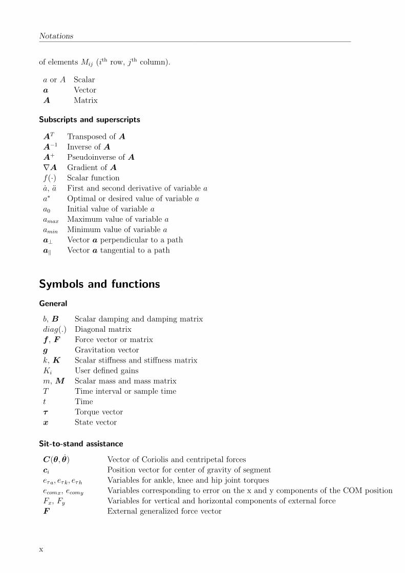
of elements Mij (ith row, jth column).
a or A Scalar
a Vector
A Matrix
Subscripts and superscripts
AT Transposed of A
A−1 Inverse of A
A+ Pseudoinverse of A
∇A Gradient of A
f(·) Scalar function
a, a First and second derivative of variable a
a∗ Optimal or desired value of variable a
a0 Initial value of variable a
amax Maximum value of variable a
amin Minimum value of variable a
a⊥ Vector a perpendicular to a path
a‖ Vector a tangential to a path
Symbols and functions
General
b, B Scalar damping and damping matrix
diag(.) Diagonal matrix
f , F Force vector or matrix
g Gravitation vector
k, K Scalar stiffness and stiffness matrix
Ki User defined gains
m,M Scalar mass and mass matrix
T Time interval or sample time
t Time
τ Torque vector
x State vector
Sit-to-stand assistance
C(θ, θ) Vector of Coriolis and centripetal forces
ci Position vector for center of gravity of segment
eτ a, eτ k, eτ h Variables for ankle, knee and hip joint torques
ecomx, ecomy Variables corresponding to error on the x and y components of the COM position
Fx, Fy Variables for vertical and horizontal components of external force
F External generalized force vector
x
Notations
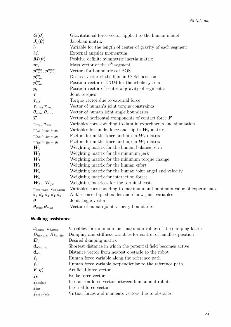
G(θ) Gravitational force vector applied to the human model
Jk(θ) Jacobian matrix
li Variable for the length of center of gravity of each segment
Mz External angular momentum
M (θ) Positive definite symmetric inertia matrix
mi Mass vector of the ith segment
pminzmp, pmaxzmp Vectors for boundaries of BOS
ptarcom Desired vector of the human COM position
ptarcom Position vector of COM for the whole system
pi Position vector of center of gravity of segment i
τ Joint torques
τext Torque vector due to external force
τmin, τmax Vector of human’s joint torque constraints
θmin,θmax Vector of human joint angle boundaries
T Vector of horizontal components of contact force F
vexp, vsim Variables corresponding to data in experiments and simulation
w2a, w2k, w2h Variables for ankle, knee and hip in W2 matrix
w3a, w3k, w3h Factors for ankle, knee and hip in W3 matrix
w4a, w4k, w4h Factors for ankle, knee and hip in W4 matrix
W1 Weighting matrix for the human balance term
W2 Weighting matrix for the minimum jerk
W3 Weighting matrix for the minimum torque change
W4 Weighting matrix for the human effort
W5 Weighting matrix for the human joint angel and velocity
W6 Weighting matrix for interaction forces
Wf1, Wf2 Weighting matrices for the terminal costs
vexp,max, vexp,min Variables corresponding to maximum and minimum value of experiments
θ1, θ2, θ3, θ4, θ5 Ankle, knee, hip, shoulder and elbow joint variables
θ Joint angle vector
θmin, θmax Vector of human joint velocity boundaries
Walking assistance
dθ,min, dθ,max Variables for minimum and maximum values of the damping factor
Dhandle, Khandle Damping and stiffness variables for control of handle’s position
Dd Desired damping matrix
dobs,max Shortest distance in which the potential field becomes active
dobs Distance vector from nearest obstacle to the robot
f‖ Human force variable along the reference path
f⊥ Human force variable perpendicular to the reference path
F (q) Artificial force vector
fb Brake force vector
fapplied Interaction force vector between human and robot
fint Internal force vector
fobs, τobs Virtual forces and moments vectors due to obstacle
xi

Notations
fsupport Desired support force vector
k Positive constant gain
kC,e, kC,θe User-defined variables
Kh, Kr Force gain variables
K Stiffness matrix
Md Desired mass matrix
Menv, Denv Mass and damping matrices for environment situation
PA(t+ 1) Variable for probability of the human preference for choice A at time t+ 1
pT,C Variable for normalized task performance
rz(t) Variable for obtained reward for choice z
Th Transformation matrix
Th, Tb Geometrical transformation matrices
U(q) Vector of artificial potential field
wA(t), wB(t) Variable for accumulated evidences for choosing option A or B
λ Variable for forgetting factor
µ Variable related to slope of the sigmoid function
θe Variable for orientation error between the reference path and the global x-axis
θref Desired orientation variable
Fall prevention assistance
Dd,arm,i Desired damping matrix for either left or right arms
Ftot, Ttot Vectors of total interaction forces and moments
hi Distance vector between the robot handles and the center of robot handles
Md,arm,i Desired inertia matrix for either left or right arms
xCOM, yCOM , zCOM Variables of COM position vector
v, ω Variables for control inputs for linear and angular velocities
Supervision-based safety control
Dt Damping coefficient for the contact point t
Dr Robot’s dissipation matrix
Di Dissipation matrix for the robot(s) or human
eR,r Robot’s effort vector
fR,r Dissipative robot’s joint torques
(fI , eI) Interaction port variables
(fR, eR) Resistive port variables for energy dissipation
(fS, eS) Energy storage port variables
(fC , eC) Control port variables
F Variables for linear space of flows
F∗ Variables for dual linear space of efforts
f , e Variables for power-conjugate port variables: flow and effort
Inr Identity matrix of order nrIo Inertia matrix of object
G Mapping matrix
H Hamiltonian function
xii

Htot Total energy of the system
Hmax Maximum limit of the total energy of the system
HT Hamiltonian of the energy tank
Jr Jacobian matrix of robot r
Mo Total mass of object
Mr Inertia matrix of robot r
m Total number of collaborative robots
nr Number of DoFs of robot r
Pc,r Power injected by the controller of robot r
Ph Power passing through the HRI port
Pmax Maximum power passing through the HRI port
R Symmetric dissipation matrix
R0l Rotation matrix
r Robot r
sT State variable of energy tank
Ur(qr) Robot gravitational energy
u, y Input and output variables
Wh,max Total performed work
xdes,r Desired robot configuration
zt Binary variables for interconnection of subsystems to manipulate
z Modulating factor
Ψi Ψj Reference frames


1 Introduction
Due to demographic changes in the world, the number of elderly persons will dramatically
increase. In 2015, twelve percent of the global population (900 million) was aged 60 or
over, and this is growing at a rate of 3.26 per cent per year. This group will represent
nearly a quarter of the world’s population by 2050 [1]. As chronic age-associated diseases
such as dementia and adverse clinical events such as falls with high impact on motor
performance increase exponentially with age, mobility associated disability will also increase
exponentially. In addition to basic activities relating to individual hygiene and basic needs
such as eating, key motor features such as walking and transfer situations are affected.
Mobility is known to be a crucial ability as ambulation and transfers are required for
many activities of daily living. Mobility disabilities endanger independence and have
negative consequences on quality of life and self-esteem. Physical activity was found to
have a positive effect, especially if performed long-term [2, 3], while low physical activity
and motor performance is known to be a risk factor for age-associated health decline with
clinical consequences such as risk of falling [4, 5].
The rising demand for mobility assistance is endangered by an increasing lack of qualified
care workers, decrease in social support systems (family members) and the immense costs
for care. Thus, part of the requests have to be covered by assistance technologies. The
development of mobility assistance robots (MARs) became of great interest in the last two
decades. A series of devices have been developed by various groups, see [6] for an overview.
These devices can provide physical, sensory, and cognitive support as required for those
who have lost a portion of their capabilities.
How to safely and efficiently control such devices to satisfy the user’s need is a challenge
that is the main focus of this thesis.
1.1 Challenges
The presented work focuses on supporting human mobility and thus enforcing fitness and
vitality by developing proper assistive approaches for intelligent MARs designed to provide
user-centred and natural support for ambulating in indoor environments. This thesis
envisions the design of cognitive and biologically-inspired approaches that can interpret
specific forms of human activity or decision making in order to deduce what the human
needs are, in terms of mobility and to provide user and context-adaptive assistance to
elderly users, and generally to individuals with specific forms of moderate to mild walking
impairment. A big challenge raised in this respect, and therefore focused in this thesis, is
on safe, intuitive, and user and environment-adaptive control designs of MARs as detailed
as follows:
Intuitiveness: The human-robot shared controller should be designed in order to
result in intuitive and natural support to the human user. From our point of view,
1

1 Introduction
“intuitive and natural” means that the robot behavior is compatible with the support
provided by another person (e.g. a nurse). Such design of the robot shared control
is a challenging task, since an assistance robot under full user’s authority can have
difficulties guaranteeing acceptable performance and safety due to cognitive, sensorial
and physical weaknesses down to target users being either elderly or disabled persons.
On the other hand, a fully autonomous system that ignores the user’s intention can
result in an overall non intuitive behavior and therefore user’s dissatisfaction and
even dangerous situations in case of human and robot disagreement. Therefore, a
shared control approach which takes the user’s intention into account, but at the
same time exploits all benefits of robotic systems should be considered for assistance
robots. However, how to adapt the behavior of the shared control system based on
environment conditions, history of user’s performances, and the user’s physiological
state is still considered a major research challenge. An intuitive and natural behavior
can be achieved if the robot can similarly mimic the human’s motion or if it can decide
on the provided level of assistance in a similar way to humans. Thus, human motor
control models and decision-making formalisms are considered in the formulation of
the robot control design in order to improve the intuitiveness of the robot’s behavior.
User and environment adaptation: The robot’s behavior should enhance the overall
human-robot interaction behavior by being aware of the context of the operation.
The robot should reason and adapt its operational behavior based on the environment
state as well as the user’s behavior and his/her physiological state, postural stability or
intentions. Such adaptations are critical requirements in the design of a context-aware
robot control resulting in improvement of the quality of interaction between the MAR
and human.
Safety : The MARs should behave safely since they have to operate in close interaction
with humans, more specifically elderly or patients with cognitive and/or physical
impairments. Safety is one of the most important features of MARs since any hardware
or software failure may put users at risk. Therefore, as a basic requirement, the
MARs control architecture should guarantee the user’s safety.
A possible technical realization of the above mentioned features within the control
system of MARs can consist of components shown in Fig. 1.1. At the lowest level of
the architecture a series of mode-dependent control modules can be found that drive the
mobility assistant and parametrize its low-level controller. To guarantee safety, a safety
supervision module ensures that certain velocity, force and energy limits are not exceeded
and the robot stays within a given workspace required for the specific mode of control
used. Furthermore, the architecture can include a series of modules for online sensor data
recording and pre-processing for determination of the environment state as well as human
behavior analysis. An example can be data coming from Kinect or laser scanners employed
on the robot to detect obstacles and to refine the environment information. Multimodal
sensor data streams can be further passed to a larger group of modules dealing with
human behavior analysis as well as action, plan and intention recognition. In this context
modules can be foreseen for the human performance and stability analysis, the physiological
state recognition, speech recognition, and gesture recognition as well as action, plan, and
2

1.1 Challenges
Figure 1.1: A general control architecture for mobility assistance robots.
intention recognition. These modules provide required information for the controllers that
aims for intuitive and user and environment-adaptive robot’s behavior. The core of the
architecture is represented by an agent for assistance optimization. The main idea is that
this agent optimizes the level of physical, cognitive and sensorial assistance provided to
the user in each specific control mode of robot operation, depending on the status of the
human behavior and environment state.
This thesis is dedicated to the design of the modules indicated in dashed in Fig. 1.1
(referred as “General control modules”), with specific focus on proposing solutions related
to three already-reviewed challenges and therefore realizing safe, intuitive and natural as
well as human and environment-adaptive robot’s behavior during interaction with human
users. To this aim, control approaches are designed for three main operational modes
of sit-to-stand (STS), walking and human’s fall prevention. Safety aspects are firstly
taken care of in the control design for each mode of operation. Moreover, it is further
emphasized by the realizing of a general safety supervisory controller. The latter supervises
the behavior of the specific control unit in the specified mode of operation and reshapes the
robot’s behavior to enhance the user’s safety if an unsafe situation is about to happen. In
respect of the goal of intuitive and adaptive robot reaction, an analysis of human motions,
human to human assistance as well as human decision-making policies are presented to help
better understand the underlying principles, and therefore to mathematically formulate and
employ them in the robot control design. These principles are used within the assistance
optimization to decide on the optimal level of provided robot support. This thesis also
aims for practical validation of the proposed approaches with real end-users. The major
parts and contributions of this thesis are described hereafter in more detail.
3

1 Introduction
1.2 Main Contributions and Outline of the Thesis
The goal of this thesis is the development of controllers for mobility assistance robots in
three main modes of operation including sit-to-stand transfer, walking and fall-prevention.
As graphically shown in Fig. 1.2, a key component of the techniques discussed throughout
this thesis is assistance optimization, which is considered in the design and evaluation
phases of the assistance approaches for each mode of operation. Assistance optimization
is investigated through development of natural, user and environment-adaptive control
concepts, that incorporate online gained knowledge about environment, user, or task in the
control law. Chapters 3-5 present how the above-mentioned control concepts are realized for
the main three operational modes. Moreover, in chapter 6, energy-based safety-enhancing
approaches are realized to monitor and improve the behavior of the robot in order to
enhance the human’s safety during human-robot collaboration.
Figure 1.2: Outline of the thesis.
The main contributions of this work as well as further details of the developed approaches
are presented as follows:
• Comprehensive study of rollator-type mobility assistance robots: Over the
years, several MARs have been developed, however a complete review of their em-
ployed hardware and functional capabilities was missing in literature. Chapter 2
focuses on MARs of rollator type and provides a detailed review of their systems
and implementations of functionalities. The systems are grouped according to their
actuation, kinematic structure as well as employed sensors and human-machine inter-
faces. Functionalities consider mainly sit-to-stand and stand-to-sit assistance, walking
assistance, cognitive assistance, and health monitoring. Different implementations of
these functionalities are reviewed followed by individual discussions about the current
state of the art in this field and possible future directions.
4

1.2 Main Contributions and Outline of the Thesis
• Biologically-inspired robot control for human sit-to-stand transfers: Sit-to-
stand (STS) transfers are a common human task which involves complex sensorimotor
processes to control the highly nonlinear musculoskeletal system. Understanding
and imitating the human behavior during STS transfers provides a powerful tool to
control assistance robots towards an intuitive and natural behavior of the coupled
system of human and robot. Previous works on human STS transfer assistance hardly
incorporate computational models of the motions, and STS transfers were mainly
studied and analyzed in explorative and hypothesis-driven experiments. Chapter 3
goes beyond the state of the art and formulates typical unassisted and assisted human
STS transfers as optimal feedback control problem that finds a compromise between
task end-point accuracy, human balance, energy consumption and smoothness of the
motion and takes human biomechanical control constraints into account. Accuracy
of the proposed modelling approach is evaluated for different healthy and elderly
subjects by comparing simulations and experimentally collected data. Finally, the
proposed STS model is used to determine optimal assistive strategies suitable for a
person either with weakness in specific part of the body or more general weakness.
These strategies are implemented on a robotic mobility assistant and are intensively
evaluated by 33 elderly subjects who are mostly not able to perform unassisted STS
transfers. The validation results show a promising STS transfer success rate and user
satisfaction.
• Adaptive shared control for walking assistance: A main application of MARs
is to provide support to elderly or patients during walking. The design of a safe and
intuitive assistance behavior is one of the major challenges in this context. Chapter
4 presents an integrated approach for the context-specific and on-line adaptation of
the assistance level of a rollator-type MAR by the gain-scheduling of low-level robot
control parameters. For the first time, a human-inspired decision-making model, the
Drift-Diffusion Model, is introduced as the key principle for gain-scheduling parameters
and to adapt the provided robot assistance in order to achieve a human-like assistive
behavior. The shared control approach is designed to provide a) cognitive assistance
to help the user following a desired path towards a predefined destination as well as b)
sensorial assistance to avoid collisions with obstacles while allowing for an intentional
approach of them. Further, the robot observes the user’s long-term performance and
fatigue to adapt the overall level of c) physical assistance provided. For each type of
assistance, a decision-making problem is formulated that affects different low-level
control parameters. The effectiveness of the proposed approach is demonstrated
in technical validation experiments. Moreover, the proposed approach is evaluated
in an intensive user study with elderly persons. Obtained results indicate that the
proposed gain-scheduling technique incorporating the ideas of human decision-making
models shows a general high potential for the application in adaptive shared control
of mobility assistance robots.
• Robot control for human fall prevention: Mobility assistance robots with
actuated arms can provide physical and balance support preventing falls of elderly
people or patients. In chapter 5, for the first time a fall prevention approach is
5

1 Introduction
proposed for a MAR equipped with a pair of actuated arms. The algorithm evaluates
the user’s balance criteria and determines required supportive forces to be provided to
the user in order to prevent user falls. This chapter further presents how the required
forces are realized by the robot. Performance of the proposed approach is tested in
experiments by a mobility assistance robot supporting subjects provoking falls in
different directions.
• Supervisory control for safe human-robot collaboration: Safety is a major
challenge on control design of not only MARs, but also any robotic system having
physical interaction with humans. While collision detection and contact-related injury
reduction in physical human-robot interaction has been studied intensively in literature,
safety issues in physical human-robot collaboration (pHRC) with continuous coupling
of human and robot(s) (that is the common case of assistance robotic applications)
has received little attention so far. In chapter 6, an energy monitoring control system
is developed that observes energy flows among the different sub-systems involved in
pHRC, shaping them to improve human safety according to selected metrics. The Port-
Hamiltonian formalism is used to model each sub-system and their interconnection.
An energy-based compliance controller that enhances safety by adapting the robot’s
behavior is proposed and validated through extensive simulations.
Finally chapter 7 summarizes the contributions and main results of the thesis and
highlights future research directions.
6

2 Review of Mobility Assistance Robots andtheir Functionalities
The development of MARs has become of great interest in the last two decades. A series
of devices have been developed by various groups, see [6] for an overview and [7] for an
application-oriented view. The two main categories of mobility assistants are robotic
wheelchairs and robotic walkers [8]. The latter can again be divided into three main groups
[9]: the Standard Walking Frames (aka Zimmer Frame), designed to provide support to a
person with lower limb weakness, the Rollators which are a standard frame with attached
wheels used where balance is the major problem, and the Reciprocal Frames which are
similar to the Standard Frames except that the frame is hinged on either side allowing the
sides of the frame to be moved alternately. Reciprocal Frames are designed to accommodate
a normal walking pattern with opposite arm and leg moving together.
Although several MARs have been developed over the years, a comprehensive review
of their employed hardware and functional capabilities was missing from literature. This
chapter provides a detailed and complete review of the MARs’ system and implementations
of functionalities. Different systems are compared by their kinematics, actuation system,
sensors, and human-machine interfaces (HMI), see section 2.1. We discuss different imple-
mentations of provided functionalities like sit-to-stand and stand-to-sit (STS) assistance
(section 2.2.1), walking assistance (section 2.2.2), cognitive assistance (section 2.2.3), health
monitoring (section 2.2.4) as well as extra functionalities realized for very few systems
(section 2.2.5). After having reviewed platforms and realized functionalities along with
their various implementations we conclude with a summary. It should be noted that the
intention of this chapter is to review functionalities from an engineering perspective and
not from a human factors or clinical point of view as available literature shows a lack
of formal evaluation studies with patients and thus, does not allow us to make strong
conclusions about the benefits of developed systems and functionalities from a clinical and
users’ perspective. We summarized our findings and recommendations for future evaluation
studies in a separate survey paper, see [10].
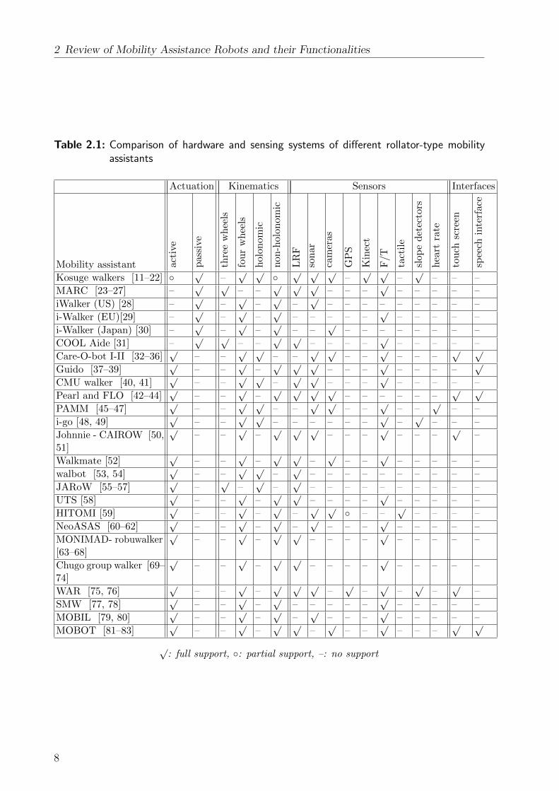
2.1 Mobility Assistance Platforms
In the following sections we review kinematics and actuation systems, sensors as well as
interfaces used for a total number of 27 mobility assistance robots of rollator type, see
Table 2.1 for a summary.
7
2 Review of Mobility Assistance Robots and their Functionalities
Table 2.1: Comparison of hardware and sensing systems of different rollator-type mobilityassistants
Actuation Kinematics Sensors Interfaces
Mobility assistant acti
ve
pass
ive
thre
ew
hee
ls
fou
rw
hee
ls
holo
nom
ic
non
-holo
nom
ic
LR
F
son
ar
cam
eras
GP
S
Kin
ect
F/T
tact
ile
slop
ed
etec
tors
hea
rtra
te
tou
chsc
reen
spee
chin
terf
ace
Kosuge walkers [11–22] ◦√
–√ √
◦√ √ √
–√ √
–√
– – –
MARC [23–27] –√ √
– –√ √ √
– – –√
– – – – –
iWalker (US) [28] –√
–√
–√
–√
– – – – – – – – –
i-Walker (EU)[29] –√
–√
–√
– – – – –√
– – – – –
i-Walker (Japan) [30] –√
–√
–√
– –√
– – – – – – – –
COOL Aide [31] –√ √
– –√ √
– – – –√
– – – – –
Care-O-bot I-II [32–36]√
– –√ √
– –√ √
– –√
– – –√ √
Guido [37–39]√
– –√
–√ √ √
– – –√
– – – –√
CMU walker [40, 41]√
– –√ √
–√ √
– – –√
– – – – –
Pearl and FLO [42–44]√
– –√
–√ √ √ √
– – – – – –√ √
PAMM [45–47]√
– –√ √
– –√ √
– –√
– –√
– –
i-go [48, 49]√
– –√ √
– – – – – –√
–√
– – –
Johnnie - CAIROW [50,51]
√– –
√–√ √ √
– – –√
– – –√
–
Walkmate [52]√
– –√
–√ √
–√
– –√
– – – – –
walbot [53, 54]√
– –√ √
–√
– – – – – – – – – –
JARoW [55–57]√
–√
–√
–√
– – – – – – – – – –
UTS [58]√
– –√
–√ √
– – – –√
– – – – –
HITOMI [59]√
– –√
–√
–√ √
◦ – –√
– – – –
NeoASAS [60–62]√
– –√
–√
–√
– – –√
– – – – –
MONIMAD- robuwalker[63–68]
√– –
√–√ √
– – – –√
– – – – –
Chugo group walker [69–74]
√– –
√–√ √
– – – –√
– – – – –
WAR [75, 76]√
– –√
–√ √ √
–√
–√
–√
–√
–
SMW [77, 78]√
– –√
–√
– – – – –√
– – – – –
MOBIL [79, 80]√
– –√
–√
–√
– – –√
– – – – –
MOBOT [81–83]√
– –√
–√ √
–√
– –√
– – –√ √
√: full support, ◦: partial support, –: no support
8

2.1 Mobility Assistance Platforms
2.1.1 Actuation
Literature distinguishes between mobility assistants that are passive or active. Passive
mobility assistants are considered systems that can not accelerate by themselves and rely
on applied user’s forces, while active mobility assistants are considered to have motors to
drive the system and thus, their motion and interaction behavior can be actively controlled.
Passive systems provide passive support by guiding or decelerating the user with the help
of brakes when needed, e.g. to avoid collisions. Safety is inherently guaranteed for passively
assisting robots because of their dependency on external forces that have to be applied by
the user. On the other hand, poor maneuvering capabilities and rather high inertia are
considered disadvantages of passive systems as the whole robot load needs to be pushed
by the human applying forces onto it. In contrast, active-type robots can be featured
with many components since their active mobile base carries their weight. A manual or
automated (motorized) brake system is typically used in both passive and active systems.
Among the overall 26 mobility assistant robots reviewed, only 6 devices were found to
belong to the passive category, while 21 devices belong to the active category, see Table 2.1.
2.1.2 Kinematics
Mobility assistants can be mainly categorized into devices with locomotion support and
with STS support. In the following subsections we report typical kinematic features of
systems belonging to each of these categories.
Rollator-type Devices with Locomotion Support
Rollator-type devices with locomotion support typically consist of three or four wheel
systems. Four wheel devices typically consist of a support frame, two castors at the front,
and two actuated rear wheels. Only few prototypes are equipped with motorized wheels at
the front and non-motorized wheels at the rear (e.g.[84]), motors on all four wheels (e.g.
[40]), or represent passive systems without motors at any wheel (e.g. [12, 28]). Three-wheel-
systems are typically based on commercially available frames equipped with sensors and
handles. They often employ an automated braking and steering system for the front wheel
(e.g. [24, 31]).
Four wheel configurations have been used in 24 platforms, while three wheel configurations
have only been used in 3 systems.
Mobility assistance robots can employ holonomic or non-holonomic mobile bases. Most
of the available prototypes (17 systems) use non-holonomic mobile bases, while the rest (8
systems) use holonomic bases either with four omni-directional wheels (see CMU walker[41]
and ’walbot’ [53, 54]), two omnidirectional wheels plus castors (see PAMM, [46, 47]), or
even three omnidirectional wheels (see JAIST Active Robotic Walker (‘JARoW’) [55–57]).
More versatile kinematic structures have been investigated only in very few prototypes.
Examples found in literature include the test of a handrail instead of handles in an early
version of the ’walbot’ [53, 54], a re-configurable structure from a walking support system
into a chair [52], as well as the mounting of an additional manipulator arm for manipulation
of objects [85].
9

2 Review of Mobility Assistance Robots and their Functionalities
Rollator-type Devices with STS Support
In total 6 mobility assistance robots include STS assistance mechanisms in their kinematic
structures. Different kinematic structures were realized for each of the systems. Parallel
actuated arms with 2 DoFs mounted on an active mobile base are proposed in “MONIMAD”
and its predecessor “robuWalker” [63–68]. The same concept, but with independently
controlled spindle drives for each arm is followed for the Mobot platform [81, 82]. For both
aforementioned devices the handles are designed to keep the same orientation while moving.
A 3 DoF support pad manipulated by four parallel linkages mounted on an active mobile
base was developed by the group of Chugo [69–74]. A prerequisite for this platform though
is that the patient must lean on the pad (by his/her chest), place the arms on the two
arm holders and grip the two handles during sit-to-stand transfers. The supporting pad
assures the patient’s postural stability while performing a STS transfer. Finally, a concept
for adjusting the height of the handles or arm support by reconfiguring either the base
mechanism is proposed in three more systems, see[75, 76], [86], and [77, 78].
2.1.3 Sensors
Most developed prototypes are equipped with laser range finders, sonar, and force torque
sensors, while cameras are less used. GPS, Kinect, and tactile sensors are so far only rarely
employed. More specific sensors such as a slope detection sensor was found in [48, 49],
heart-rate sensors in [46, 47], and tactile sensors in [59].
Laser range finders or sonar sensors are mainly used for the purpose of navigation or
obstacle avoidance, see e.g. [46, 47, 84]. Only some groups use laser range finders to
distinguish different user’s states (walking, stopped, and emergency) [87], or to detect the
user’s lower limb positions and speed [55–57]. Force torque sensors are mainly employed
for the evaluation of interaction forces applied by the user. Only in [29] force sensors are
used at the rear wheels to measure ground reaction forces. Cameras are employed for
localization [28, 46, 47, 59], obstacle avoidance [75, 76], or documentation of the user’s
behavior for rehabilitation purposes [30]. Self localization by means of GPS/GIS is only
studied in [75, 76].
2.1.4 Human-Machine Interfaces
A series of human machine interfaces (HMI) have been investigated in the context of mobility
assistant robots. Manual switches or buttons to receive control inputs from the user and
speakers to provide information about the robot states are the most basic HMIs used [40, 84].
A hand-held remote control is being used in [40] to send signals to the robot from distance.
More advanced systems using displays and touchscreens are employed in [42, 51, 75, 88]
to provide a graphical interface for switching between different robot control modes [88],
walking characteristics [51] or to set a destination [42, 75]. Further information in form of a
front camera-view of the robot, the current location, and guidance messages is displayed in
[42, 75]. Speakers and microphones are also used for verbal communication, see e.g. [88, 89].
Since elderly people often have difficulties interacting through keyboards and computer
screens, verbal communication has been tested as alternative. Care-O-Bot 3 is equipped with
10

2.2 Functionalities
a simple speech synthesis function to process user’s verbal commands as well as to provide
speech feedback to the user during task execution [88, 89]. Advanced real-time speech
recognition and synthesis functionalities are implemented in Pearl and Flo ([42, 43, 90])
based on CMU’s SPHINX II system [91].
In the following sections we will provide details about the specific functionalities realized
with the various hardware platforms.
2.2 Functionalities
Functionalities of robotic mobility assistants are reviewed and classified into STS assistance,
walking assistance, cognitive assistance, health monitoring, and some extra functionalities
that don’t fall into these categories and that were realized only for few systems. In general,
walking and cognitive assistance are implemented in most mobility assistants, while the
rest of functionalities have been less focused on so far.1 Table 2.2 provides an overview of
available functionalities in all reviewed prototypes.
2.2.1 STS Assistance
Different robot control approaches have been investigated to provide STS assistance. As
some controllers differentiate between different STS phases we also report on approaches to
estimate postural states during STS transfers.
Estimation of Postural State
Only very few manuscripts could be found that consider the detection of different postural
phases during STS movements for providing STS transfer assistance. Pasqui presents a
fuzzy logic to distinguish between seven different phases in STS transfers: seated, returned,
pre-acceleration, acceleration, start rising, and rise [67]. In [98] the same type of fuzzy logic
estimator is presented, but with a reduced number of phases. In [69] authors distinguish
between four phases: still sitting and inclining the trunk forwards, lifting off from the chair,
lifting the body and extending the knee completely. Phase three is detected by observation
of the interaction force and its comparison with a predefined threshold. The other phases
are not detected explicitly. It is remarkable though that no evaluation could be found
that aimed at determining how many and which of the phases are essential for control and
beneficial for realizing an STS functionality.
Human Balance Criteria
Human balance is a critical issue to be considered in STS transfers. The most used balance
criterion applied in the context of mobility assistants was found to be the Zero Moment
Point (ZMP), which is defined as the point at which the net moment has no component
along the horizontal axes. If the ZMP lies within the support polygon, the configuration
can be considered stable [103].
1Please note that the length of the following sections varies depending on the available material found inliterature.
11

2 Review of Mobility Assistance Robots and their Functionalities
Table 2.2: Comparison of developed functionalities by different rollator-type MARs
Mobility assistant FunctionalityWalking assistance Cognitive
assistance
ST
Sas
sist
ance
Man
euve
rabilit
yim
pro
vem
ent
Hum
anfa
llpre
venti
on
Gra
vit
yco
mp
ensa
tion
onsl
opes
Obst
acle
/ste
pav
oidan
ce
Ass
iste
dlo
caliza
tion
Ass
iste
dnav
igat
ion
Ort
hot
icfu
nct
ions
Hea
lth
mon
itor
ing
Extr
afu
nct
ional
itie
s
Kosuge walkers [11–22, 87, 92] ◦√ √ √ √
– – – – –MARC [23–27] –
√– – ◦ – – – – –
iWalker (US) [28] – – – – –√ √
– –i-Walker (EU)[29] – – – – – ◦ ◦ – – –i-Walker (Japan) [30] –
√ √– – – – – – –
COOL Aide [31] –√
– –√
– – – –Care-O-bot I-II [32–36, 93–95] – – – – – –
√– –
Guido [37–39, 84] –√
– –√ √ √
– –CMU walker [40, 41] – – – –
√ √ √– – –
Pearl and FLO [42–44, 90] – – – –√
–√ √ √ √
PAMM [45–47] –√ √
–√
–√
–√
–i-go [48, 49, 96] –
√–
√– –
√– – –
Johnnie - CAIROW [50, 51] – –√
–√
– – –√ √
Walkmate [52] –√
– – – – – – – –walbot [53, 54] –
√– –
√–
√– – –
JARoW [55–57] –√
– –√
– – – – –UTS [58] – – – –
√– – – – –
HITOMI [59] – – – –√ √ √
– – –NeoASAS [60–62] –
√– – – – – – – –
PAM-AID [97] –√
– – – – – – – –MONIMAD - robuwalker [63–68,98, 99]
√– – – – – – – – –
Chugo group walker [69–74]√
– – – – – – – – –WAR [75, 76]
√– – –
√–
√– – –
SMW [77, 78]√
– – – – – – – – –MOBIL [79, 80]
√– – –
√– – – – –
MOBOT [81–83, 100–102]√ √ √
–√ √ √
– – –
√: full support, ◦: partial support or just sketched support, –: no support
12

2.2 Functionalities
It should be mentioned though that the ZMP has been mainly applied and studied in
robotic applications, but it is unknown whether humans follow similar balance-keeping
principles. Thus, a future research direction may target the investigation of human stability
criteria that can also be implemented for mobility assistants.
Robot Control for STS Transfers
Surveying implementations for assisted STS transfers we found that different control
approaches were realized that can be grouped into three categories: force control, motion
control, and switching control.
STS Support by Robot Force Control: In terms of robot force control very basic interaction-
force-minimizing optimization-based approaches were found with posture stability criteria
used as side criterion. Mederic and Pasqui evaluate the Zero Moment Point (ZMP) for
a simplified human model [65] and control the interaction force between user and robot
to stabilize the configuration. Their model considers a 7 link mechanism studied in the
sagittal plane.They evaluate the ZMP position and formulate an optimization problem that
determines appropriate interaction forces to be applied to the user during a STS transfer by
means of force control to stabilize the configuration of the ZMP within its support polygon.
STS Support by Robot Motion Control: An alternative approach to realize STS transfers
is to command the motion of the platform or arms.
The simplest form is studied in [16] where the authors use a very basic, passive approach
to assist in STS transfers that positions the support system in a fixed position in front
of the user and activates the brakes of the system, while the user grasps the handles to
perform a STS transfer by using the weight of the support system to assist in STS transfers.
A more sophisticated approach is studied in [77, 78] where STS transfers are guided by
the trajectory of a support plate mounted on the developed robot called SMW. The support
plate is designed to balance the user as well as to support specified portions of the patient’s
weight during the STS transfers. The desired trajectory is implemented by controlling the
linear actuator guiding the angle and height of the support plate. The authors propose
two predefined trajectories and compare their characteristics using the force/torque data
measured by sensors at the top plate.
Pasqui and Mederic investigate least effort user-centered natural trajectories in order to
effectively assist a patient in STS transfers. They define natural trajectories as paths that are
“compatible with hand movements when the STS transfer is assisted by someone/something
else” as well as paths leading to a “smooth and continuous motion”. Based on the
biomechanical data analysis of recorded STS transfers, the authors approximate the recorded
hand paths with cubic splines [64]. The global trajectory shape was found to be highly
related to the initial and final point of the handle rather than other factors such as
patient’s age, height or pathology. In [66, 99] authors achieve smoothness of trajectories
by minimizing jerk along the path [104]. In [64] they finally present very preliminary
results towards the optimization of parameters defining an S-shaped curve in order to
reduce human effort. They implement 5 trajectories with different parametrization using
impedance control and ask patients to interact with the device while guiding them on
the predefined compliant trajectory. The implementation with least deviation from the
controlled trajectory is selected as the best for a specific subject. More formal optimization
13
2 Review of Mobility Assistance Robots and their Functionalities
methods are mentioned in the authors future work.
A more advanced approach for the determination of optimal assistive strategies to be
performed by a mobility assistant is presented in [83, 100]. Typical unassisted and assisted
human STS transfers are formulated as an optimal feedback control problem that finds
a compromise between task end-point accuracy, human balance, jerk, effort, and torque
change and takes further human biomechanical control constraints and external forces
provided by the robot handles into account. Optimal handle trajectories to be controlled
during STS transfers are determined by offline dynamic optimization for either a person
with specific body segment weakness or more general weakness.
Finally, in [21] the authors present an online approach that takes over parts of the
required knee torque. Instead of pre-calculating the whole trajectory, they introduce a
motion control algorithm that moves the support system following an admittance control
law based on the currently measured interaction force and the desired support knee torque,
which is calculated as the scalar product of the applied force at the handle and the distance
of the handle to the human knee. Three accelerometers are attached to shank, thigh
and trunk of the user to determine joint angles. Using these joint angles in combination
with the human model joint torques are calculated [105, 106]. In order to simplify the
implementation, only gravity effects are considered and no inertia, which is acceptable for
slow STS transfers. The same simplification has been also made in [105].
STS Support by Switching Control: Again another approach for providing assistance
during STS transfers is to switch between different controllers depending on the actual
human postural state.
The Chugo group initially proposed a switching position/damping control for their
stationary STS assistance system [69] consisting of a support bar with two degrees of
freedom and a bed system which can move up and down. Their approach assists in sit-to-
stand and stand-to-sit transfers by exploiting the remaining physical strength of a patient
in order to not decrease the force generating capacity of the patient. Inspired by [107],
they divide the standing up motion into four phases: i) still sitting and inclining the trunk
forwards, ii) lifting off from the chair, iii) lifting the body and iv) extending the knee
completely. Analyzing these four phases by means of multi-body computer simulations
and assuming a Kamiya motion strategy to perform the STS transfer, they conclude that
assistance is mainly required in the third phase in order to reduce the required knee torque,
while in the other phases maintaining stability of the body is sufficient. Based on these
considerations they realize compliant impedance control for phase 1, 2, 4 and an admittance
controller with force reference implementing damping control for phase 3. Force sensor
readings and a predefined force threshold are used to switch between the phases. In
early versions [108], the authors adopt this approach for the bed system only, while they
implement a force control approach for the support bar.
Later, authors adapted their approach of the initial stationary system to their mobile
mobility assistant. This system foresees a force sensor attached to the support pad to
switch between position and damping control. Recent improvements of their system include
further the real-time estimation of the patient’s pelvis, knee and ankle load based on a
biomechanical model of the human and the switching between control modes depending on
predefined thresholds in these loads [74] as well as the real-time estimation of the center of
14

2.2 Functionalities
gravity (COG) of the user based on force sensor measurements [71] and its PID control
by changing the position of the mobile base of the assistance robot. Finally, the assisting
approach was also extended to stand-to-sit transfers by changing the reference trajectories
[73] and by including sensor readings to adjust the seating position [72].
Instead of switching based on predefined thresholds, Pasqui presents a fuzzy controller
to ensure stability of the patient during assisted STS transfers [67, 98]. They subdivide
the STS transfer into several phases and define fuzzy rules to evaluate these phases as well
as to evaluate the center of pressure and the horizontal component of the handle force
to guarantee stability for the patient by switching between different controllers named
“normal”, “admittance”, “stabilization”, and “return”, basically implementing different
variations of admittance control.
More control-theoretic considerations investigating stability of the resulting hybrid and
switched systems are currently lacking in literature. Also the optimal number of phases
needed for achieving best STS support can be considered still an open research question.
2.2.2 Walking Assistance
Walking assistance is the functionality, which is present in almost all mobility assistant
robots reviewed in this thesis and means the human-adaptive or environment-adaptive
manipulation of robot control inputs or control parameters to ease the steering of the
mobility assistant or to avoid safety-critical situations like collisions with obstacles or falls,
some of them requiring the estimation of the human postural state as reviewed next.
Estimation of Postural State
User postural state estimation in the context of walking assistance has been studied in
[13, 14, 16, 22, 23, 26]. States like walking, stopped and emergency are considered. As key
feature to distinguish between these states the Kosuge group used the distance between the
user and the rollator which is measured by means of a laser range finder. Differentiating this
distance and knowing about the velocity of the rollator allows them to calculate the user
velocity. Stopped state estimation of the user is realized by simply comparing the velocities
of the user and the rollator along the heading direction. Walking and emergency states are
distinguished by analyzing the distance between the user and the rollator during walking
without tumbling or falling, and comparing the current user position to the histogram of
his/her position in x- and y-axis (ellipsoids) with respect to the position of the rollator
[14]. If the relative position of the user is found within the ellipsoid, the user state is
detected as walking. If the relative position of the user is found outside of the ellipsoid,
the user is considered to be in emergency state. Recently, the same group presented a
very similar approach to estimate user states, but using a depth vision sensor instead of a
laser range finder and analyzing the centroid of the user’s upper body [18]. Doing so, a
2D probabilistic model of the human location is constructed during normal walking. The
centroid of the upper body is used to judge whether the user is walking normally or is
in an emergency state. Please note that the state-specific parameters were found to vary
significantly depending on the user’s size, physical capability, operational characteristics
and disabilities. They also vary depending on the daily or environment conditions. Thus,
15
2 Review of Mobility Assistance Robots and their Functionalities
Hirata and Kosuge propose a continuous update of the estimation based on the actual user
or environment conditions.
Following a slightly different approach, Huang et al.proposes a fall detection scheme
based on simultaneous monitoring of the user head position by a CCD camera mounted
above the user and leg positions measured by a laser range finder directed towards the user
legs [109]. Possible falling states are categorized into “forward falling”, “backward falling”
and “sideward falling”. Probability distributions of the distance between head position and
the center of the two legs for the normal walking and falling state are the key features in
the proposed fall detection scheme. If the head position lies outside a given distribution for
the normal walking situation a falling state is detected.
In [14, 101] the authors propose a method for estimating user falls by evaluating the
relative distance between the robot and user’s legs measured by a laser range finder. In [12]
an extended approach proposed for modelling the user with a solid body-link model, online
tracking its configuration with the help of two laser range finders mounted at different
heights, determining the user center of gravity and finally checking whether this center
of gravity lies within the defined support polygon formed by the area of both feet. The
risk of falling increases if the projection of the COG leaves the support polygon. Human
falls have been characterized into falls along the horizontal direction caused for example
by stumbling and leading to legs that are far apart from the walker, and falls along the
vertical direction caused for example by weak legs. Evaluation of the human’s extrapolated
center of mass (XCOM) for faster fall detection was proposed by [82].
Summarizing, mainly walking, stopped, and emergency states have been determined by
processing features like human-robot distance and human COG position. Falls as critical
emergency situations have been studied by monitoring the user’s head, upper body or leg
positions during walking. Full-body articulated tracking of the user, however, is hardly
realized, most likely due to the lack of adequate sensor systems at the time the studies
were performed.
Human and Environment-adaptive Motion Control
When it comes to providing assistance during walking, human and environment-adaptive
motion control has been intensively studied in literature.
One of the most often adopted approaches in this context is variable admittance control.
In case of an active mobility assistant variable admittance control allows reacting to
estimated user intentions and user states with a corresponding motion behavior of the
mobility assistant. An admittance model with the human force fh as input and the system
reference velocity x as output defines the sensitivity of the device to applied human forces.
Further, the desired admittance dynamics is extended by additional forces/torques frgenerated based on environment information and applied by the motors on the system
Mdu+Ddu = KhThfh +KrTrfr (2.1)
with Md and Dd to be specified desired mass and damping matrices, Th, Tr geometrical
transformations and Kh and Kr weighting factors. A low-level velocity controller finally
guarantees that the device follows the calculated reference velocity u. By online adapting
16
2.2 Functionalities
the admittance parameters for mass and damping, changing the transformation matrices
Th, Tr, weighting factors Kh and Kr or additional forces/torques fr generated based on
environment information, the behavior of the system can be modified.
For passive mobility assistants in contrary, the desired admittance model (2.1) can not
be realized anymore actively, but only passively by dynamically activating brakes resulting
in
Mdu+Ddu = KhThfh −KrTbfb (2.2)
with fb the brake force and torque.
Alternative approaches to variable admittance control consider a direct commanding
of the position or velocity of the platform, using approaches that allow determining the
human intention either directly from input devices or indirectly via estimation from sensor
signals and context.
In the following paragraphs we detail implementations found that are based on the
aforementioned concepts and that aim at maneuverability improvement, fall prevention,
gravity compensation on slopes or obstacle avoidance.
Maneuverability Improvement: Basic concepts of maneuverability improvement to
reduce the inertia of the overall system are realized for many active mobility assistants.
Variable admittance control as defined in (2.1) is implemented to reduce the apparent inertia
compared to the uncontrolled system, see e.g. [102]. In [52] authors compare a force-velocity
mode and a force-acceleration mode and conclude that the force-acceleration mode has
better stability and maneuverability, but the force-velocity mode has a faster response.
Depending on the location of the force sensors and the type of interaction points, further
different force components need to be distinguished. In [61, 62] the user is e.g. provided
physical support on the lower arms rather than by gripping handles with his/her hands and
thus, authors identify three force components: vibrations introduced by the floor/walker
wheels imperfections, oscillations due to user’s trunk motion during gait, and the voluntary
components related to the user’s navigational intention. They develop adaptive filtering
techniques to separate the different force components and use them to control the device
by means of a Fuzzy-logic-based controller.
In [17, 22] authors further improved maneuverability by applying a transformation Thin (2.1) that allows to online modify the center of rotation of the mobility assistant.
For the PAMM robot [45] the transfer from the stopped to walking state and vice
versa was supported by slowly fading from high/low to low/high damping parameters by
implementing a velocity-dependent damping. A similar approach is proposed by Song [53],
but using a force observer instead of a force/torque sensor in order to reduce the costs of
the device.
Finally, artificial potential fields are employed in [11, 15, 92, 110] to derive force com-
ponents in (2.2) for passive path following by activating brakes accordingly. In [30] they
implement a line following behavior with their passive-type robot using similar principles.
Authors in [39, 84] and [54] study an active type robot, but limit active robot behavior
for path and wall following to the angular velocity and activate it only in case the human
applies intentional forces on the robot.
17

2 Review of Mobility Assistance Robots and their Functionalities
In contrary, authors in [55–57] don’t apply a variable admittance approach, but estimate
user’s lower limb and body locations using a Kalman-filter-based tracking scheme and
use this information as input to the platform low-level controller that adjusts the motion
corresponding to the user’s walking behavior.
Also in [26] authors directly command a reference trajectory. This trajectory is derived
by estimating the user’s intended path from a combination of sensory data, user’s input,
history and device position and orientation by means of a dynamical path weighting scheme
that weights a series of possible arcs starting at the current position of the mobility assistant
and pointing into different directions. The arc with the highest probability is used to set
the front wheel steering angle.
In [31] the authors use forces and moments a user applies to a walker’s handle in addition
to information on the local environment and the walker’s state to derive the most likely
human intention, respectively path to follow. Depending on the identified intention, the
angle of the front wheel is set by the mobility assistant, leaving the user the freedom to
decide on the velocity to move on the identified path. Dempster-Shafer theory is adopted
to extract the user’s navigational intention from historical observations and evidences.
Interaction forces are evaluated to identify conflict situations based on a defined “conflict
index”, which influences the selection of the most likely human intention.
Also in [97] authors combine user’s and environment’s input for maneuverability im-
provement. The PAM-AID mobility assistant, which was designed for frail and elderly
blind, is equipped with a user-interface with three buttons for moving forward, turning left
or right and that activate respective autonomous robot behavior. To avoid erroneous inputs
to the system caused by the reduced sight of the patients, the authors propose a Bayesian
network that combines user’s input with high-level environment information derived from
sensors to provide a context-aware estimate of the human navigational intention, which is
finally realized by means of a local potential field navigation scheme.
Fall Prevention: Another crucial assistance function provided by mobility assistants is
fall prevention. For the active-type robot PAMM [45] high damping values were abruptly
set in (2.1) to quickly stop the walker in case of emergency.
In [50] the gait of Parkinson Desease patients is analyzed with the help of a Hidden
Markov Model and auditory cues are provided when abnormal gaits are recognized. Further,
the walker is locked with the help of motors when sudden forward pushing is detected to
avoid falls.
For the i-Walker (Japan) system, authors control the platform velocity for fall prevention
triggering braking torques of the passive-type platform if its velocity exceeds certain
predefined limits [30].
In [12, 14], varying admittance control on a passive mobility assistant is used for fall
prevention by increasing the damping in the desired admittance if the user was found to be
in a “falling” state activating the brakes accordingly, while in the “stopped” state, large
brake torques were applied to each of the wheels independently of the user’s applied force
to the system.
More sophisticated fall prevention controllers that actively move the robotic platform or
arms to stabilize the human posture are rarely studied. One exception was found in [101]
18
2.2 Functionalities
where a supervision-based safe motion control based on invariance control for forward fall
and human-robot collision avoidance is presented. Human-robot distance is used as safety
feature to formulate safety-constraint-admissible state space regions that are kept invariant
by proper switching between a nominal (admittance) and a corrective controller, whenever
one of the predefined safety constraints are about to be in violation.
Finally, authors in [82] propose an approach for a mobility assistance robot with actuated
arms. They evaluate the human XCOM and present a control system for the articulated
arms to apply required forces on the human for fall prevention and for recovering balance.
Gravity Compensation: Gravity compensation on slopes is a further assistance function
provided by mobility assistance robots. To realize gravity compensation for downhill walk,
authors in [15] derived the brake torques in (2.2) using measurements of two tilt angle
sensors added to their passive mobility assistance robot.
A motion control algorithm implementing an active mode that realizes gravity compen-
sation on slopes for uphill walking is realized in [96], whereby a model-predictive controller
is employed to provide an estimate of the slope height.
Obstacle Avoidance: Finally, obstacle avoidance is a typically implemented assistance
function for mobility assistance robots. In [11, 15, 92, 110] artificial potential fields are
employed to derive force components fb in (2.2) for passive obstacle avoidance. In contrary,
in [20] force/torque components fr in (2.1) are employed for active obstacle avoidance.
The latter, however, can result in dangerous situations, for example in case the human
releases the handles and the robot continuous to move or the human plans to walk on a
straight path, while the system accidently turns to circumvent an obstacle. Thus, in [31]
authors directly influence the angular velocity of the front wheel in the vicinity of obstacles
and activate the obstacle avoidance behavior only in case the calculated repulsive virtual
moment exceeds a certain limit. A “conflict index” evaluating the interaction moment
between user and robot is used to decide on conflicting situations, e.g. when the user
intends to approach an object identified as obstacle by the autonomous robot agent. When
the conflict index exceeds a certain predefined value, the robot returns the full control to
the user. In [111] authors compare the potential field approach to an approach based on
the definition of state-based constraints in situations of static and dynamic obstacles as
well as workspace constraints. They conclude that the selection of the appropriate method
depends on the particular application as both methods have advantages in specific settings.
While approaches mentioned so far mainly implement fixed scheduling strategies for Kr,
Kh in (2.1) or (2.2) to combine user’s and autonomous robot’s inputs or switch between
extremes of fully autonomous or fully human control, the adaptive shared control with
varying force gains Kh and Kr investigated in [45] evaluates among others the proximity to
obstacles and shifts authority between computer and human by online adjusting the force
gains in (2.1) as a function of a defined performance metrics. Further, in [102] authors
propose an approach for the context-specific, on-line adaptation of the assistance level
of a rollator-type mobility assistance robot by gain-scheduling of low-level robot control
parameters in (2.1) by means of a human-inspired decision-making model, the Drift-Diffusion
Model. Among other assistances, authors also implement a sensorial assistance allowing to
19
2 Review of Mobility Assistance Robots and their Functionalities
avoid collisions with obstacles, but also the intentional approach of them. Finally, in [25]
the authors propose to shift authority from the human user to the robotic system or vice
versa depending on the specific context, allowing for the implementation of a no assist mode,
an assist mode, a safety mode and an override mode. In the no assist mode the rollator is
under full control of the user. In the assist mode the robotic walker software senses obstacles
in the current path, and provides assistance so that neither the human nor the walker frame
finally collide with one or more of the obstacles by still taking the human navigational
intention into account. In the safety mode, the walker software has detected an obstacle
within a distance threshold that requires an immediate response and thus, the system takes
over the control of the platform by paying less attention to the human intention. Finally,
the override mode allows the user for the intentional approach of an obstacle by overriding
the autonomous functions of the walker software. Unfortunately, authors only sketch the
general capabilities of their architecture, but do not provide mathematical implementation
details about the reasoning and logic unit used, nor do they provide experimental results.
Alternative approaches to variable admittance control, e.g. adjust the mapping between
user’s lower limb and body locations and the velocity of the platform as a function of
the distance to obstacles (e.g. in case the platform lacks a force sensor, see e.g. [55–57]).
Similarly, in [50] the velocity of the platform is adapted as a function of the measured
distance of the human user to the platform trying to keep this distance constant, while
adjusting the maximum angular and translational velocity in the vicinity of obstacles. In
[58] authors implement an obstacle avoidance and local path planning functionality based
on the Vector Field Histogram algorithm and fuse human and autonomous agent velocity
inputs by means of a fuzzy logic module as decision making unit. Finally, in [54] authors
adapt only the angular velocity of the platform as a function of the distance to obstacles,
while the human decides on the translational velocity leading to a pure passive approach.
The Guido system again realizes a fully autonomous mode in which laser scanner data is
used to create a local point map to detect obstacles and to elastically deform the originally
planned path to avoid collisions [39, 84].
2.2.3 Cognitive Assistance
Frequent relocations between hospital, rehabilitation centre and nursing home can lead
to confusion and disorientation. Thus, cognitive assistance in terms of localization and
navigation has frequently been implemented for mobility assistants. In addition cognitive
orthotic assistance may become important, which means the reminding of people about
routine activities.
Localization and Navigation
The implementation of assistance functionalities like localization and navigation require
solving technical issues like map building, localization, and path planning. In the following
paragraphs we fist review methods that have been tested in the context of mobility assistant
robots before we introduce assistance functionalities of localization and navigation that use
these techniques in the context of mobility assistance robots.
20
2.2 Functionalities
Early methods, considered the combination of local methods for robot localization based
on odometry and gyroscopes with global localization methods that compare laser scan data
and natural features observed in the environment with a given map and features, see [93].
Later, map-based navigation and more recently simultaneous localization and mapping
(SLAM) algorithms are implemented. In the Guido systems [39, 84] for example the most
sophisticated approach solves the SLAM problem with an extended Kalman filter (EKF)
for estimating a feature-based map, composed of the walls of the environment. The Guido
system is featured to build the map of an environment in a few minutes by either manually
or autonomously driving around. Another robot navigation system for assistive walkers
has been built using the Carnegie Mellon’s Navigation Toolkit (Carmen), a probabilistic
software system, which has been developed in the context of different robot guidance
projects. It contains software modules for collision avoidance, localization, mapping, path
planning, navigation, and people tracking and uses metric environment maps at its core.
Localization is realized with the help of conditional particle filters. In [44] authors further
present advanced localization techniques for highly populated areas like the cafeteria.
In terms of path planning, the Guido system plans the shortest path to the target with
respect to its nonholonomic constraints of the mobile platform using a graph-based method
[39, 84]. As the generated path does not take dynamic obstacles into account, laser scanner
data is used to create a local point map to detect obstacles and to elastically deform the
original path to avoid collisions. No path modifications by the user are possible in the Guido
framework. In [33] authors suggest different types of path planning methods including
rapidly exploring random trees, potential grids with wavefront expansion, quad trees, and
visibility graphs [93, 95] as well as variants, which have been extended for non-holonomic
platforms [95] based on a static map and a target in this map. To allow for dynamic
obstacles and planning of smooth paths as well as path modifications according to user’s
inputs, advanced methods for dynamic path planning (e.g. elastic bands [112]) are employed
as presented in [34, 94, 95]. In the context of the Carnegie Mellon’s Navigation Toolkit
(Carmen), the navigation module integrates collision avoidance and global path planning
methods based on dynamic via point calculation.
In the following paragraphs we report on found assistance functionalities of localization
and navigation that take advantage of introduced methods for mapping, localization, and
path planning.
Assisted Localization: While a series of mobility assistance robots have an embedded
functionality for localizing themselves, only few also use this information and implement a
localization assistance functionality for the user. In [28] and [40, 41] the user’s position
is visually marked on a map displayed on the platform. In contrary, in [59] information
on landmarks is provided via Braille, while automatic verbal feedback about the current
location, navigation events or selected goals is provided in [39, 84].
Assisted Navigation: Realized functionalities for assisted navigation typically foresee
that users either manually mark desired target locations in a given map [102], select from
a given list on a screen using buttons ([40, 41] and [76]), use switches to select a specific
21
2 Review of Mobility Assistance Robots and their Functionalities
labelled target location [39, 84], send orders via voice or via a remote like a Bluetooth or
Wi-fi device [47], or the system interacts with the user via a dialogue system to determine
the desired target location [44].
In terms of guiding behaviors, guidance can either be provided by controlling the robot
motion, providing visual or auditory cues, or by mixed versions of the above.
Most platforms provide assisted navigation by controlling the robot motion behavior.
Examples can be found e.g. in [44], where the Pearl robot guides people to desired target
locations by estimating the person’s velocity to properly online adjust the guiding speed.
In [45] an adaptive shared control with varying force gains evaluates the user’s perfor-
mance by combining multiple criteria like the proximity to obstacles, the deviation from the
planned trajectory and human stability criteria to finally online shift the control authority
between computer and human and with this to determine the robot motion behavior.
In [33] authors study three different navigation assistances under the assumption of
a given static map and target in this map. The first implementation guides the user at
constant speed with activated automatic path planning and obstacle avoidance. The second
implementation uses automatic path planning and obstacle avoidance, but lets the user
decides on the velocity. Finally, the third implementation advances the second one by the
possibility of modifying the path by the user.
In [54] a goal seeking behavior is designed for an omni-directional mobile robot by
evaluating laser sensor data and by fusing this assistive behaviors with further behaviors
like obstacle avoidance and wall following by means of a Fuzzy Kohonen Clustering Network.
The goal seeking behaviour is designed to redirect the mobile robot so that it moves again
towards a desired goal direction, which comes from a path planning algorithm. The active
robot behavior is limited to the angular velocity and is activated only in case the human
applies intentional forces on the mobility assistant. The translational motion is commanded
by the user by applying translational interaction forces to the mobility assistant.
The motion control algorithm proposed by the Ko group and implemented on the robot
walking helper called “i-go” combines passive and active control modes [96]. The passive
mode implements a braking control law to differentially steer the vehicle and guide the user,
while the active mode realizes gravity compensation on slopes. The gain that controls the
brakes is online adapted using the theory of differential flatness depending on the current
user force and speed of the mobility assistant as well as the planned path of the robot to a
given target destination.
Finally, in [102] authors propose an integrated approach for the context-specific, on-line
adaptation of the assistance level of a rollator-type mobility assistance robot by gain-
scheduling of low-level robot control parameters. A human-inspired decision-making model,
the Drift-Diffusion Model, is introduced as the key principle to gain-schedule parameters and
with this to adapt the provided robot assistance in order to achieve a human-like assistive
behavior. Among context-aware sensorial and physical assistances, also cognitive assistance
is provided to help the user following a desired path towards a predefined, pre-selected
destination.
In contrary to these implementations that define the robot motion behavior to provide
navigation assistance, authors in [28] developed a navigation assistance system that provides
verbal and visual instructions and interfaces with a smart world with embedded RFID tags
22

2.2 Functionalities
for localization.
In [40] again arrows overlaid on a map are tested to guide users from a given start
to a desired target point on a given map. In a slightly different implementation authors
investigate a mixed mode of providing user assistance in form of controlled robot motion
and visual cues. A passive, active and forced robot control mode are implemented on
the platform [41]. The passive mode leaves full control over the trajectory by the user
focusing only on obstacle avoidance, the active control shifts to full autonomous control and
compares the user’s estimated trajectory with the desired one and if a deviation greater
than a certain given angle is detected the robot slows down and eventually halts if the
user does not realign with the desired robot path. An additional user interface showing
arrows that point into the direction of the next waypoint has been tested in this mode to
communicate the robot intention to the user. In the forced mode the robot has full control
over the platform motion and the user input is only used to switch the robot motion on
and off.
Orthotic Functions
Cognitive orthotic functions that remind the user about routine activities and guide her/him
to desired locations are rarely incorporated in today’s mobility assistance robots. In [43, 90]
authors develop a higher level reasoning software that provides cognitive orthotic assistance
by reminding people about routine activities such as eating, drinking, taking medicine and
using the bathroom. Three modules, a Plan Manager, a Client Modeler and a Personal
Cognitive Orthotic are combined into the so called Autominder architecture. The plan
manager models client plans as disjunctive temporal problems. The Client Modeler uses a
reasoning formalism in form of a Quantitative Temporal Bayes Net. The Personal Cognitive
Orthotic finally uses a Planning-by-Rewriting approach to create a high-quality reminder
plan that satisfies the caregiver and client.
2.2.4 Health Monitoring
Health monitoring functionalities are among the more rarely implemented functionalities in
mobility assistance robots.
In the PAMM system a continuous health monitoring system is installed that supervises
the user’s speed and applied forces as well as heart rate. Further, force/torque sensor
data is used along with odometry information to study the user’s gait and to analyze the
stride-to-stride variability derived from the velocity power spectrum density [47].
The CAIROW walker records the statics of the user gait as basic health evaluation and
monitoring function [50]. Gait analysis is specifically performed for patients with Parkinson
disease by monitoring the step length, velocity, and acceleration of each leg for each step.
As a result, the gait analyzer specifies the type of the gait as Festinating Gait (i.e. patient
walks with small steps), Freezing of Gait (i.e. patient normally grips the handle tightly and
their leg muscles become stiff), and Normal Gait (i.e. in other conditions). This statics
of the patient’s gait is aimed to be either used in the platform motion control or to help
therapists in the rehabilitation process.
23
2 Review of Mobility Assistance Robots and their Functionalities
The mobility assistance robots Pearl and Flo are designed to collect statistical data on
medication, daily living activities and even factors related to prediction of specific medical
risks based on e.g. blood sugar and leg diameter, but this system has only been partially
implemented [43, 90].
Summarizing, health monitoring functionalities have only rarely been combined with
mobility assistance robots and are limited to basic functions like the analysis of heart rate
and gait. More advanced and long-term health monitoring functionalities have not been
explored yet. Similarly the implementation of training functions to gradually improve or
maintain the current health status are not considered so far.
2.2.5 Extra Functionalities
Extra functionalities can be found in few of the surveyed mobility assistance robots.
Occasionally basic functionalities for phone and Skype call, entertainment and social
interaction as well as telepresence have been realized.
In [51] phone and Skype call possibilities for fast contact of the patient to a doctor are
provided.
Flo and Pearl’s speech recognition system is capable to understand a variety of questions
related to daily living activities such as inquiries for the television program and the weather
forecast ([42, 43, 90]). Thanks to wireless internet connection, the dialog manager can
connect to a number of online external sources of information to provide answers to questions
on a number of topics [42].
Emotional feedback as a higher level human-robot interaction is implemented in the
Flo system, which is equipped with an actuated face and allows showing different facial
expressions by modifying the angle of its mouth, eyebrows, and eyes [42].
Moreover, Flo allows for virtual visits of doctors or nurses using its telepresence interface
consisting of an onboard camera and microphone that transmit the video and audio signals
to a remote station, and a joystick on the remote side, which allows a health care giver,
friend or relative to drive the robot around the user’s rooms, and also direct the robot’s
gaze by controlling the head configuration [42].
Finally, in order to reduce the boredom of the exercise, authors in [51] developed an
online music player for their walker. The platform is connected to the Internet, and allows
users to select their preferred music.
2.3 Summary and Discussion
In this chapter a total number of 5 passive and 20 active rollator-type mobility assistance
robots were reviewed from a perspective of system design and functionalities. Most
reviewed systems were found to be active, based on four wheels and to have a non-
holonomic kinematics, which is the same as the considered system for control development
in this thesis. Main functionalities were identified as sit-to-stand and stand-to-sit transfer
assistance, walking assistance, cognitive assistance as well as health monitoring.
In terms of sit-to-stand and stand-to-sit transfer assistance, three categories of robot
control have been implemented: position control, force control and switching control. These
24
2.3 Summary and Discussion
approaches mainly rely on results from hypothesis-driven experiments in which researchers
investigated chair, subject and strategy-related determinants of STS-transfers to find best
STS trajectories to be realized by the mobility assistance robot. However, concerning robot
control, analysis of human STS transfers and posture stability mechanisms (both during
unassisted and assisted STS transfers) could help to better understand underlying principles,
to mathematically formulate them and to develop proper robot assistive controllers. To
this end, chapter 3 goes beyond the state of the art and proposes computational models for
unassisted and assisted STS transfers.
Concerning the walking assistance, performance of the system was found to be enhanced
mainly by the tuning of control parameters that change the apparent impedance of the
system based on high-level environment or user information. This approach was successfully
realized to actively avoid obstacles and steps and compensate for gravity on slopes. So
far, however, mainly fixed scheduling strategies have been employed in the tuning laws.
In this respect, chapter 4 investigates context-dependent and dynamic authority sharing
mechanisms involving methods for decision making, to determine adaptation laws for the
MAR controller.
For human fall prevention, approaches were found that mainly aimed to determine
the states like walking, stopped, and emergency. Moreover, the braking strategy when
an emergency state is detected was found as the only available approach for human fall
prevention in literature. The states of the human were also mainly identified by looking at
the user’s head and leg positions. These indeed can be improved by considering a MAR
with actuated arms, and more sophisticated human fall detection and assistive approaches.
The latter is investigated in chapter 5.
Furthermore, safety for MARs have received little attentions so far. It was considered
in terms of posture stability measures, which are typically considered in the offline design
phase (e.g. the robot force profiles and trajectories in STS assistances). However, a more
elaborate safety analysis that goes beyond classical posture stability measures and includes
the definition of posture-dependent safe states and safe robot behaviors considering for
example the allowed energy exchange between user and robot is so far missing in current
literature, but is of crucial importance because of the tight physical coupling of human and
robot. Solutions for the user’s safety are introduced in this thesis, especially in chapter
6 where an energy-based modeling and control approach is presented for reshaping the
robot’s behavior to enhance the user’s safety if an unsafe situation is about to happen.
25
3 Biologically Inspired Sit-to-Stand Assistance
Human sit-to-stand (STS) transfers are a frequently exercised daily activity, which highly
influence the quality of life for people who are no longer able to accomplish normal STS
transfers due to either a specific or a more general muscle weakness.
Development of a proper STS assistance strategy to be provided by a MAR is one of
the main goals of this thesis, and is discussed in this chapter. As reviewed in chapter 2,
only a few assistance robotic devices are focused on supporting human STS transfers so far
and their control can be grouped into three categories: motion control, force control and
switching control (see section 2.2.1 for more details). These approaches barely incorporate
computational models of natural STS transfer motions into the development of assisitive
strategies. However, understanding and imitating the human behavior during STS transfers
can provide a powerful tool to control assistance robots towards an intuitive and natural
behavior of the coupled system of human and robot.
STS transfers have been mainly studied and analyzed in hypothesis-driven experiments,
which led to a considerable amount of findings. Authors in [113] for example developed a
correlation formula to derive power from body weight and standing up duration. Authors in
[114] studied different phases and their duration for standing up and sitting down motions
and [115] divided STS transfers into 4 phases and discussed characteristics of these phases.
STS characteristics such as high torque and large range of motion in the lower limb joints
during a normal STS were reported by [113, 114, 116]. Further, studies on the categorisation
of different seat, subject and strategy-related classes were performed by [117]. In [118–121]
authors studied average time, maximal hip flexion, knee extension angle and velocities for
completion of a STS transfer. Modifications of CoM trajectories during STS transfers by
lowering the horizontal and vertical CoM displacements were found to lead to a significant
reduction of joint moments on the knee and hip, see [122]. Shifting the chair height from
65 to 115% of knee height resulted in a large change of moments in hip and knee joints, see
[123]. Moreover, minimum peak joint moments and their relation to movement time were
determined by studying a large set of experimentally collected kinematic data in [124, 125].
More findings about STS transfers are presented in reviews like [126] and [117].
While this way a huge variety of data has been analyzed by various researchers, only few
computational models to study human STS transfers have been presented so far. In [127]
and [128] authors investigated an optimal LQR formalism in the context of an optimal
tracking controller combined with a fuzzy biomechanical model, which interpolates between
two linearized models of the nonlinear four segment/bipedal dynamics around the sitting
and standing position. They optimized physiological costs when tracking a predefined ankle,
knee, hip, and pelvis reference trajectory [127, 129–132].
In [133] the author employed a cost function combining joint torques squared with
absolute head orientation. The author argues that the first term increases efficiency of the
motion, while the second term results in a stabilization of the head, but no comparison with
26

human data is performed allowing to judge whether this model is sufficient or appropriate
to model human behavior in STS transfers. The same cost function has been adopted in
[134] for the design of a STS mechanism.
In [135] authors employed dynamic optimization to determine optimal STS trajecto-
ries by considering a cost function that minimizes joint torques, torque change and the
difference between left and right ground reaction forces based on sequential quadratic
programming (SQP). They determined different weights of the single criteria for unassisted
STS transfers of healthy subjects as well as amputees, but did not study assisted STS
transfers. Moreover, critical balance criteria were not considered in their approach. Further,
from an optimization point of view, SQP is considered a method of local optimization
and thus, may lead to suboptimal solutions, while global methods based on the Hamilton-
Jacobi-Bellmann equations and dynamic programming typically suffer from the curse of
dimensionality. Both is problematic when considering biomechanical problems, as they
are typically high-dimensional and involve model uncertainties [136]. Differential Dynamic
Programming (DDP) and Iterative Linear-Quadratic Gaussian (ILQG) have been proposed
in literature to overcome aforementioned limitations. They solve the optimization problem
by dynamic programming, and lead to feedback control laws. Both are methods based on
Optimal Feedback Control (OFC) that have shown to be a powerful tool to study biological
movements and interpreting human motor behavior [136].
This chapter proposes biologically-inspired and optimal assistance approaches to be
provided by MARs. It extends the state of the art on STS assistance with respect to the
following aspects: i) mathematical modeling of the human’s STS transfers and exploiting
their underlying principles, ii) extension of the obtained models to derive the optimal
and biologically-inspired assistive strategies to be provided to the users, and iii) intensive
evaluation by real end-users. Unassisted and assisted STS transfers are formulated as
optimal feedback control problems and are solved using an iterative optimal control approach
to derive optimal assistive strategies to be provided by an assistance robot. Optimal assistive
strategies for subjects characterized by a specific or more general muscle weakness are
studied, and optimal trajectories are derived. We employ DDP that iterativelly quadratically
approximates the nonlinear system dynamics and the optimal cost-to-go function around the
current trajectory. It takes physical control constraints like torque limitations into account,
while human balance-related criteria are considered in the cost function. The modelling
approach for unassisted STS transfer is validated for 3 different human healthy subjects
and 9 elderly/patient subjects by comparing simulations and experimentally collected
data. Finally, the STS model has been used to determine user-specific optimal assistive
trajectories for 33 elderly, mostly not able (or hardly able) to perform unassisted STS
transfers. The obtained trajectories have been implemented on a robotic mobility assistant
and intensively tested by the same subjects in a formal user study. The validation results
show a promising success rate of achieved STS transfers.
This chapter is organized as follows: STS transfer modeling is formulated as an optimal
feedback control problem in section 3.1. Section 3.2 reports on capturing of experimental
data, evaluates the model and compares simulation with experimental results. Section 3.3
presents obtained optimal STS assistive trajectories for different subject classes as well as
results of the performed user study with the mobility assistance robot. Section 3.4 finally
27
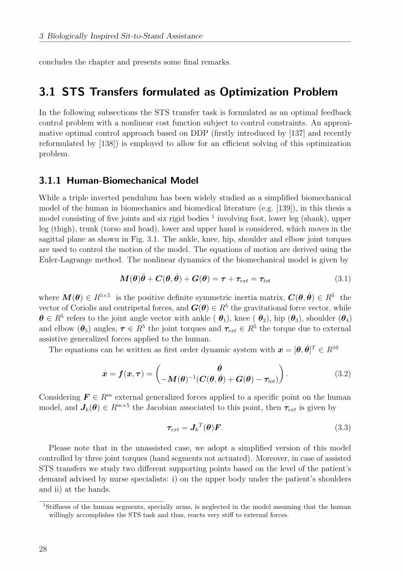
3 Biologically Inspired Sit-to-Stand Assistance
concludes the chapter and presents some final remarks.
3.1 STS Transfers formulated as Optimization Problem
In the following subsections the STS transfer task is formulated as an optimal feedback
control problem with a nonlinear cost function subject to control constraints. An approxi-
mative optimal control approach based on DDP (firstly introduced by [137] and recently
reformulated by [138]) is employed to allow for an efficient solving of this optimization
problem.
3.1.1 Human-Biomechanical Model
While a triple inverted pendulum has been widely studied as a simplified biomechanical
model of the human in biomechanics and biomedical literature (e.g. [139]), in this thesis a
model consisting of five joints and six rigid bodies 1 involving foot, lower leg (shank), upper
leg (thigh), trunk (torso and head), lower and upper hand is considered, which moves in the
sagittal plane as shown in Fig. 3.1. The ankle, knee, hip, shoulder and elbow joint torques
are used to control the motion of the model. The equations of motion are derived using the
Euler-Lagrange method. The nonlinear dynamics of the biomechanical model is given by
M (θ)θ +C(θ, θ) +G(θ) = τ + τext = τtot (3.1)
where M(θ) ∈ R5×5 is the positive definite symmetric inertia matrix, C(θ, θ) ∈ R5 the
vector of Coriolis and centripetal forces, and G(θ) ∈ R5 the gravitational force vector, while
θ ∈ R5 refers to the joint angle vector with ankle ( θ1), knee ( θ2), hip (θ3), shoulder (θ4)
and elbow (θ5) angles, τ ∈ R5 the joint torques and τext ∈ R5 the torque due to external
assistive generalized forces applied to the human.
The equations can be written as first order dynamic system with x = [θ, θ]T ∈ R10
x = f(x, τ ) =
(θ
−M(θ)−1(C(θ, θ) +G(θ)− τtot)
). (3.2)
Considering F ∈ Rm external generalized forces applied to a specific point on the human
model, and Jk(θ) ∈ Rm×5 the Jacobian associated to this point, then τext is given by
τext = JkT (θ)F . (3.3)
Please note that in the unassisted case, we adopt a simplified version of this model
controlled by three joint torques (hand segments not actuated). Moreover, in case of assisted
STS transfers we study two different supporting points based on the level of the patient’s
demand advised by nurse specialists: i) on the upper body under the patient’s shoulders
and ii) at the hands.
1Stiffness of the human segments, specially arms, is neglected in the model assuming that the humanwillingly accomplishes the STS task and thus, reacts very stiff to external forces.
28
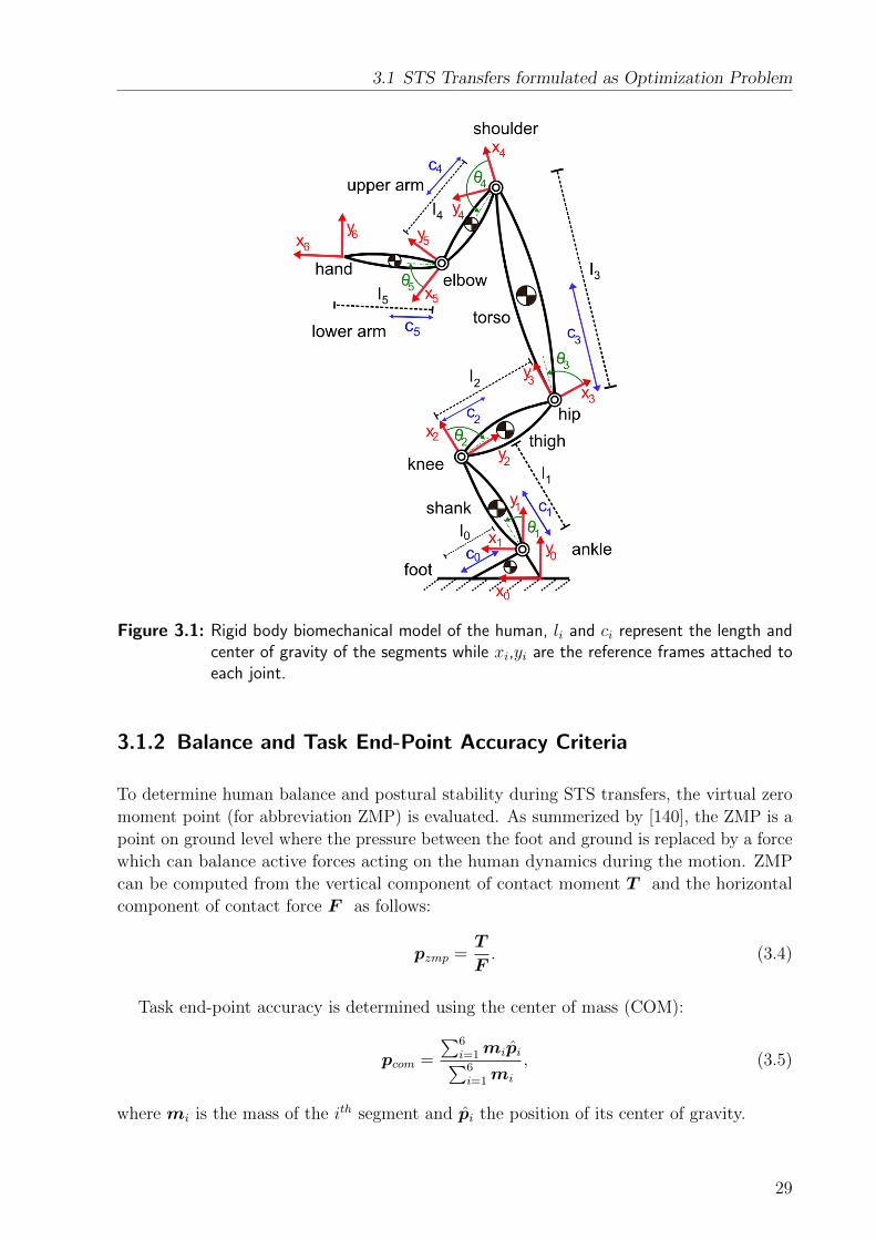
3.1 STS Transfers formulated as Optimization Problem
Figure 3.1: Rigid body biomechanical model of the human, li and ci represent the length andcenter of gravity of the segments while xi,yi are the reference frames attached toeach joint.
3.1.2 Balance and Task End-Point Accuracy Criteria
To determine human balance and postural stability during STS transfers, the virtual zero
moment point (for abbreviation ZMP) is evaluated. As summerized by [140], the ZMP is a
point on ground level where the pressure between the foot and ground is replaced by a force
which can balance active forces acting on the human dynamics during the motion. ZMP
can be computed from the vertical component of contact moment T and the horizontal
component of contact force F as follows:
pzmp =T
F. (3.4)
Task end-point accuracy is determined using the center of mass (COM):
pcom =
∑6i=1mipi∑6i=1mi
, (3.5)
where mi is the mass of the ith segment and pi the position of its center of gravity.
29

3 Biologically Inspired Sit-to-Stand Assistance
3.1.3 Formulation of Optimization Problem
The STS optimal control problem is formulated as follows: The human sitting position
with zero joint velocities is considered the initial state at time t = 0 and the position of
the COM in the steady-state standing position is considered the desired final state of the
system at time t = T . The main goal is to find a control law τ ∗ = π(x, t) that stays within
joint torque limits and that drives the system states smoothly from the initial to the final
configuration while minimizing a given cost function.
We consider three main features when defining the cost function of the optimization
problem: user’s energy consumption, smoothness of motion and control as well as user’s
balance. Minimization of energy is achieved by the effort term C4 in (3.6) that tries to
achieve a minimum time response and thus, a minimization of energy as joint torques are
much lower in the standing than in the sitting configuration (when neglecting the interaction
forces with the chair). Smooth control is achieved by the torque change term C3, while
the jerk term C2 improves smoothness of the resulting motion. As humans automatically
try to stabilize their movement patterns, human balance criteria C1 based on the ZMP are
included as well 2. The following combination of criteria is used to model the STS transfer
task:
φtotal = φfinal(x) +
∫ T
0
( 6∑i=1
Ci
)dt (3.6)
with
φfinal = φf1 + φf2
φf1(x(T )) = |pcom(x(T ))− ptarcom|2Wf1
φf2(x(T )) = |θ(T )|2Wf2
C1(x(t), τ (t)) = |pzmp(x(t), τ (t))− pmaxzmp |2W1
+|pminzmp − pzmp(x(t), τ (t))|2W1
C2(x(t)) = |...θ (t)|2W2
C3(τ (t)) = |τ (t)|2W3
C4(τ (t)) = |τ (t)|2W4
C5(x(t)) = |max(0,x(t)− xmax)|2W5
+|max(0,xmin − x(t))|2W5
C6(F (t)) = |F (t)|2W6
and Wf1, Wf2 weighting matrices for the terminal costs evaluated at the desired human
COM position ptarcom in a standing position at time T with zero joint velocities, W1 the
weighting matrix for the human balance term that aims to satisfy pminzmp ≤ pzmp(x, τ ) ≤ pmaxzmp
2Please note that a precise study of the human balance behavior during a STS is out of focus of thisthesis, but is a very interesting biomechanical research question. Currently no study focusing on thebalance criteria used during a human STS transfer that could inform the selection of these criteriacould be found in literature and therefore regulation of the human ZMP position has been consideredas a postural regulator as proposed by [141].
30

3.1 STS Transfers formulated as Optimization Problem
3, and W2 = diag(w2a, w2k, w2h), W3 = diag(w3a, w3k, w3h), W4 = diag(w4a, w4k, w4h)
the weighting matrices for the human jerk, minimum torque change and effort terms
respectively, where the term diag(.) represents a diagonal matrix4 and |v|2W = vTW v. The
weighting matrix W5 is responsible for the human joint angle and velocity boundaries
θmin ≤ θ(t) ≤ θmax and θmin ≤ θ(t) ≤ θmax. The weighting matrix W6 is considered to
minimize the interaction forces exchanged between assistance robot and human and therefore
is considered equal to zero for the case of unassisted human STS modeling. The cost function
is finally considered subject to constraints of the system dynamics formulated in (3.2) and
control constraints, i.e. τmin ≤ τ (x, t) ≤ τmax.
3.1.4 Optimal Feedback Control
We solve this optimal control problem using Differential dynamic programming (DDP)
first proposed in [137] and recently reformulated by [138]. This approach iteratively,
quadratically approximates the costs and the nonlinear system dynamics around the current
trajectory. Then, an approximately optimal control law is found by designing an affine
controller for the approximated system that enforces formulated control constraints. More
details to the algorithm is presented in Appendix B.
For our specific STS transfer problem we consider pure gravity compensating forces as
an initial guess of the control sequence, which is then iteratively improved by the algorithm
with respect to the formulated cost function.
The algorithm shows quadratic convergence in the vicinity of a local minimum, sim-
ilar to Newton’s method as presented by [142] and returns the optimal control and the
corresponding state sequences.
3.1.5 Inverse Optimal Control to Determine Cost Function Weighting
Factors
Deriving a proper set of weighting factors for the cost function is crucial to properly
model human STS transfers. We employ an Inverse Optimal Control (IOC) approach to
identify underlying optimality criteria of STS motions either for healthy subjects or patients.
Inverse Optimal Control allows to identify unknown parameters in the cost function (in
our case the weighting factors as defined in section 3.1.3) for a set of recorded human STS
trajectories. We adapt the methodology proposed by [143] to our specific problem of human
STS motions.
Given a set of recorded user’s STS motions, a cost function for the bilevel optimization
3The base of support (BOS), which determines the values of pminzmp and pmax
zmp), typically includes the sizeof the feet and the room between them for a human without external support, respectively unassistedSTS. For the assisted case, when the human firmly grasps the robot handles a larger BOS area can beconsidered. Since this, however, requires detecting whether the human stably grasps the handles, wedecided to simplify the problem and to consider the most restrictive case defined by the BOS of thehuman user only.
4Please note that same values on diagonal elements are considered for each weighting matrix.
31

3 Biologically Inspired Sit-to-Stand Assistance
problem is formulated as follows,
minW
m∑j=1
||x∗(W , tj)− xM(tj)||2 (3.7)
where the sum of the Euclidean distance between experimentally recorded states xM (tj) and
the results of the optimal control model x∗(W , tj) is used to determine optimal values for
the weighting factors W . The bilevel optimization handles iterations over weighting factors
such that the best fit between measurements and the solution of the original optimal control
problem formulated in section 3.1.3 is found. For each iteration the obtained solution of
weighting factors resulting from the bilevel optimization problem is passed to the lower
level where the original optimal control problem is solved and obtained results are reported
back to the bilevel where (3.7) is evaluated for the next iteration.
We employed the Matlab fmincon Trust Region Reflective Algorithm solver to solve the
bilevel optimization problem. Box constraints for each weighting factor were specified to
define a search space for the solver.
3.1.6 User-group Optimized STS Assistance
Finally, we use the already introduced biomechanical model and optimization approach
to calculate optimal assistive strategies for the robotic assistant that is used to support
subjects in STS transfers. We implement assistive strategies that are tailored to the specific
class and weakness of a certain subject.
In [144] a classification scheme for transfer assistance was proposed that considers the
request for supervision, type of assistance and participation of targeted persons. Here we
focus on the two classes of maximal assist, “the patient contributes with less than 25%
of the required effort to accomplish the STS task ”, and moderate assist, “the patient
contributes with at least 50% of the required effort to accomplish the STS task”. As
proposed by nursing specialists, the most common techniques for assisting persons in STS
transfers belonging to the maximal assist class foresee that the caregiver stands in front
of the person to be assisted, locks the knees and feet of the patient, grips the patient at
the upper trunk and lifts the person. Stronger patients belonging to the moderate assist
class require less physical assistance, but more balance support. In this case, the caregiver
stands in front of the patient, grasps the hands and applies forces to assist in the STS
transfer, while simultaneously assisting in keeping the patient’s balance.
Moreover, the weakness may be either limited to specific segments of the body because
of a certain disease or surgery (case a), or spread over multiple segments (case b).
For the maximal assist class, we considered that the required assistance is applied to the
upper body under the patient’s shoulders. For the moderate assist class, the interaction
point is considered on the human hands. By solving the aforementioned optimization
problem we determine optimal assistive strategies in form of robot motion trajectories.
Doing so, we consider torque constraints in the optimal control problem, which are based
on the level of the weakness in human segments (as discussed above), and constraints on
the assistive forces to be applied at the contact point(s).
The accuracy and usefulness of obtained assistive strategies highly depends on the
32

3.2 Validation of STS Model
proposed human STS model, which has to be carefully validated. Therefore, in the following
sections we study the validity of the proposed model, first for healthy subjects and then for
elderly and patients.
3.2 Validation of STS Model
In order to determine weighting factors and test the quality of the STS model against real
measurements, we performed a set of STS transfer experiments with healthy and elderly
subjects, where both cases of unassisted and assisted STS transfers were studied. In the
following sections, we report on the validation methods and obtained results.
3.2.1 Data Capturing
Capturing of STS transfer motions has been performed in two sessions, first for healthy
subjects and then for patients.
Healthy Subjects
We performed STS transfer experiments with three healthy male subjects to test the quality
of the STS model against real measurements. Their body measurements are presented in
Appendix A.
Participants were instructed to perform a few practice trials in order to find a comfortable
feet placement. They were asked to keep their feet fixed to the ground, their arms crossed
over the chest, and their upper body straight during the whole experiment (see Fig. 3.3).
Each subject was asked to repeat five STS transfers at a natural speed while the seat
heights were adjusted on an armless office chair to fit the lower leg length. Since a set of
pre-performed experiments with different subjects showed that typically people leave the
chair with upper-body inclination of about 30 degree (where zero represents the upright
trunk position), the subjects were asked to start the STS transfer with about 30-degree
initial inclination in order to reduce the effect of not-modeled chair support and therefore
allow for a fairer comparison of model and experiments.
An Xsens MVN inertial motion capture system, see [145], was used for full-body human
motion capture. The subjects were asked to wear the Xsens MVN motion capture suit which
consists of MTx miniature inertial measurement units with 3D linear accelerometers, 3D
rate gyroscopes and 3D magnetometers. These trackers are placed at strategic locations on
the human body (in the suit), to measure motion of the whole body including 23 segments
(22 joints). The accuracy of the Xsense system is highly dependent on the calibration
procedure, where subjects are asked to keep their body in some predefined configurations.
The calibration has been performed for every subject before starting recordings. In the
performed experiments a very good visual observable accuracy was achieved since the
healthy subjects could easily keep their body in the requested configurations, but as no
ground truth with an external tracking system was available no absolute numbers for the
achieved accuracy can be given. Kinematic data including segment position and orientation,
velocity and acceleration were captured with a sampling rate of 120 Hz.
33

3 Biologically Inspired Sit-to-Stand Assistance
Every STS transfer was assumed to start from the static configuration in the sitting
position and to finish when the user arrives at the fully standing position with zero joint
velocities. The average STS transfer movement time for all subjects was found to be in the
range of 1 to 2.5 seconds.
The experiments took place in the Chair of Automatic Control Engineering in September
2013, under ethical approval by the Etics review committee (Etikkomission, Fakultat fur
Medizin, Technische Universitat Munchen, Ismaninger Str. 22, 71675, Munich, Germany).
Elderly Subjects
Validation of the proposed STS model was performed using a set of recordings from 9 elderly
with varying age and gender (5 male and 4 female, from 75 to 87 years old) performing
unassisted and assisted STS transfers. The recruitment of the participants was decided
based on their cognitive and motor status. In general we targeted subjects with mild to
moderate impairment levels.
Subjects were included if they met the following criteria: (1) unable to stand up and sit
down unassisted from a normal chair or 5-chair stand test ([146]) >16.7s and (2) habitual
gait speed <0.6m/s. The cognitive impairment was screened with the Mini-Mental State
Examination ([147]) classifying patients into no, mild to moderate, or severe cognitive
impairment if MMSE provides test scores ≥26, 17–26 or <17, respectively. The participant
metadata consists of information about sex, age, height, weight as well as the cognitive and
motor impairment level are presented in Appendix A.
The experiments took place in the Agaplesion Bethanien Hospital/Geriatric Centre of the
University of Heidelberg in November 2013, with the ethical approval by the Ethics review
committee (Ethikkommission der Medizinischen Fakulteat Heidelberg, Alte Glockengießerei
11/1, 69115 Heidelberg, Germany).
Two general variations of tasks were asked to be performed by patients in order to
determine optimal policies regarding STS transfers:
a. Unassisted STS transfers: 3 repetitions of STS transfers performed in the patient’s
own preferred way without providing any instruction for initial configuration, hand
or feet positions. This was an optional task and was only performed if the patient
was able to accomplish unassisted STS transfers.
b. Assisted STS transfers: 3 repetitions of STS transfers when a passive rollator was
positioned in front of patients and they were asked to grasp its handles to receive
physical support while performing STS transfers.
The passive rollator was equipped with two 6 DOF force/torque sensors of type JR3
45E15 mounted on the rollator’s handles. Figure 3.2 presents the snapshots taken during
the unassisted and assisted STS experiments by one elderly.
Motion of the subjects was captured using a Qualisys system with 8 infrared cameras
mounted on tripods and placed around the recording area. A suitable marker set including
48 reflective markers was used to track the limb movements. The accuracy of the Qualisys
tracking system depends on the type of camera chosen, the number of cameras used in
the experiment, the size of the tracking environment, the selection of the marker sets and
34
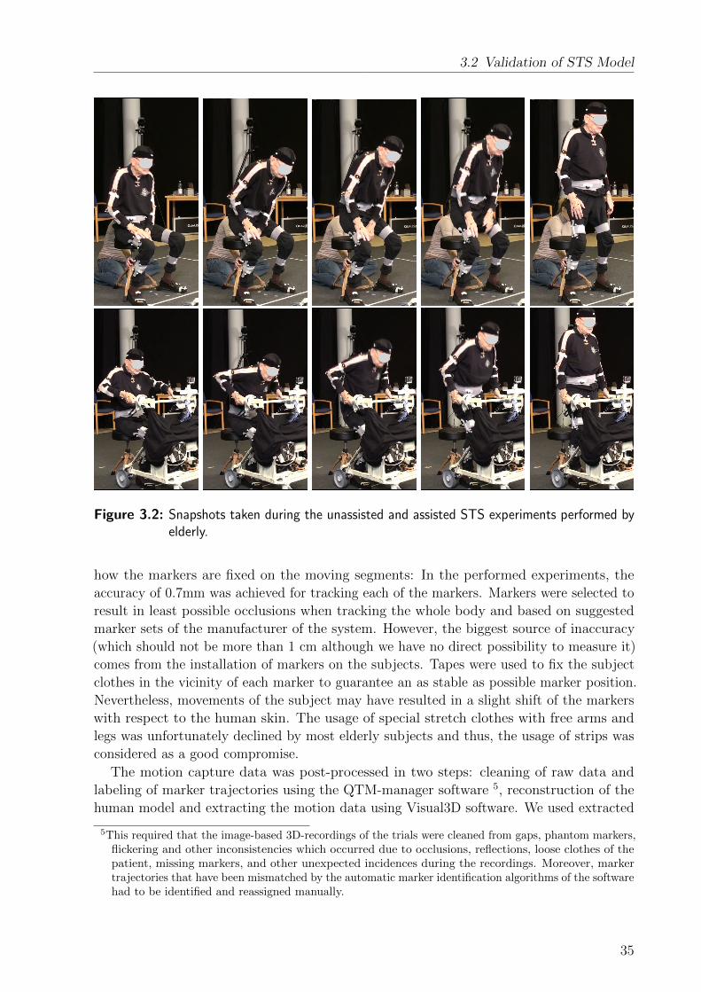
3.2 Validation of STS Model
Figure 3.2: Snapshots taken during the unassisted and assisted STS experiments performed byelderly.
how the markers are fixed on the moving segments: In the performed experiments, the
accuracy of 0.7mm was achieved for tracking each of the markers. Markers were selected to
result in least possible occlusions when tracking the whole body and based on suggested
marker sets of the manufacturer of the system. However, the biggest source of inaccuracy
(which should not be more than 1 cm although we have no direct possibility to measure it)
comes from the installation of markers on the subjects. Tapes were used to fix the subject
clothes in the vicinity of each marker to guarantee an as stable as possible marker position.
Nevertheless, movements of the subject may have resulted in a slight shift of the markers
with respect to the human skin. The usage of special stretch clothes with free arms and
legs was unfortunately declined by most elderly subjects and thus, the usage of strips was
considered as a good compromise.
The motion capture data was post-processed in two steps: cleaning of raw data and
labeling of marker trajectories using the QTM-manager software 5, reconstruction of the
human model and extracting the motion data using Visual3D software. We used extracted
5This required that the image-based 3D-recordings of the trials were cleaned from gaps, phantom markers,flickering and other inconsistencies which occurred due to occlusions, reflections, loose clothes of thepatient, missing markers, and other unexpected incidences during the recordings. Moreover, markertrajectories that have been mismatched by the automatic marker identification algorithms of the softwarehad to be identified and reassigned manually.
35
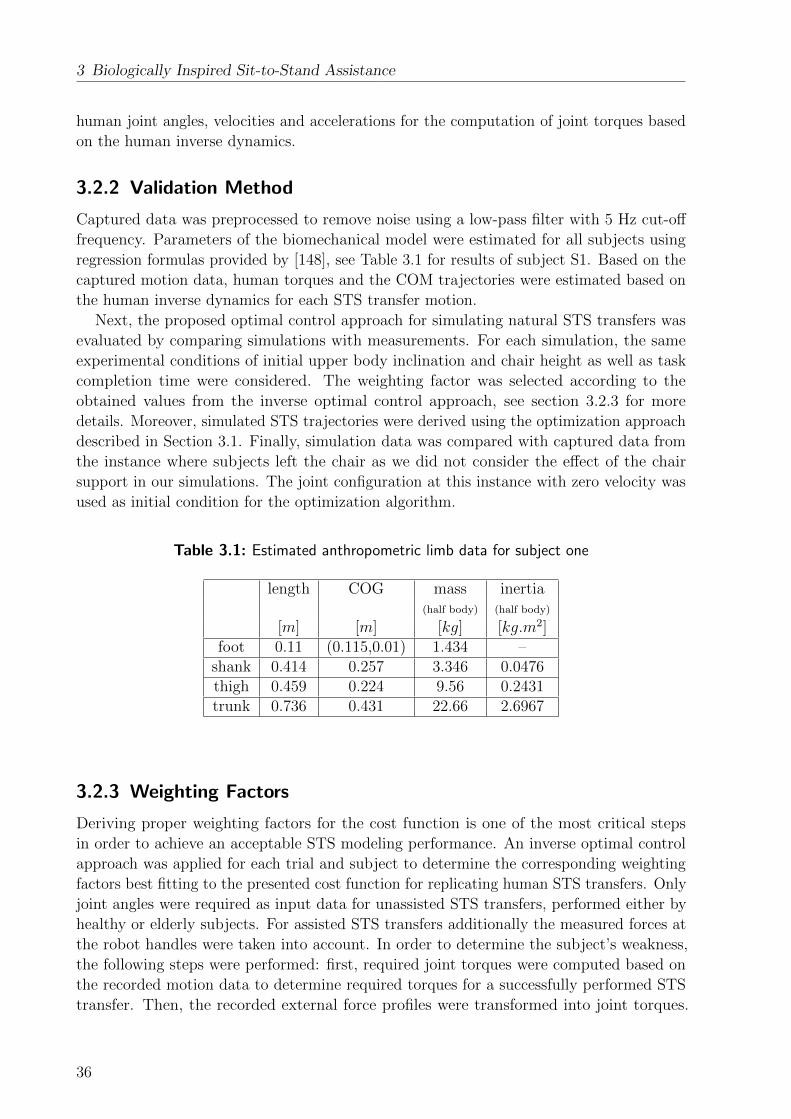
3 Biologically Inspired Sit-to-Stand Assistance
human joint angles, velocities and accelerations for the computation of joint torques based
on the human inverse dynamics.
3.2.2 Validation Method
Captured data was preprocessed to remove noise using a low-pass filter with 5 Hz cut-off
frequency. Parameters of the biomechanical model were estimated for all subjects using
regression formulas provided by [148], see Table 3.1 for results of subject S1. Based on the
captured motion data, human torques and the COM trajectories were estimated based on
the human inverse dynamics for each STS transfer motion.
Next, the proposed optimal control approach for simulating natural STS transfers was
evaluated by comparing simulations with measurements. For each simulation, the same
experimental conditions of initial upper body inclination and chair height as well as task
completion time were considered. The weighting factor was selected according to the
obtained values from the inverse optimal control approach, see section 3.2.3 for more
details. Moreover, simulated STS trajectories were derived using the optimization approach
described in Section 3.1. Finally, simulation data was compared with captured data from
the instance where subjects left the chair as we did not consider the effect of the chair
support in our simulations. The joint configuration at this instance with zero velocity was
used as initial condition for the optimization algorithm.
Table 3.1: Estimated anthropometric limb data for subject one
length COG mass inertia(half body) (half body)
[m] [m] [kg] [kg.m2]foot 0.11 (0.115,0.01) 1.434 –
shank 0.414 0.257 3.346 0.0476thigh 0.459 0.224 9.56 0.2431trunk 0.736 0.431 22.66 2.6967
3.2.3 Weighting Factors
Deriving proper weighting factors for the cost function is one of the most critical steps
in order to achieve an acceptable STS modeling performance. An inverse optimal control
approach was applied for each trial and subject to determine the corresponding weighting
factors best fitting to the presented cost function for replicating human STS transfers. Only
joint angles were required as input data for unassisted STS transfers, performed either by
healthy or elderly subjects. For assisted STS transfers additionally the measured forces at
the robot handles were taken into account. In order to determine the subject’s weakness,
the following steps were performed: first, required joint torques were computed based on
the recorded motion data to determine required torques for a successfully performed STS
transfer. Then, the recorded external force profiles were transformed into joint torques.
36

3.2 Validation of STS Model
−0.6−0.4−0.2 0 0.20
0.2
0.4
0.6
0.8
1
1.2
1.4
1.6
1.8
2
−0.6−0.4−0.2 0 0.20
0.2
0.4
0.6
0.8
1
1.2
1.4
1.6
1.8
2
−0.6−0.4−0.2 0 0.20
0.2
0.4
0.6
0.8
1
1.2
1.4
1.6
1.8
2
−0.6−0.4−0.2 0 0.20
0.2
0.4
0.6
0.8
1
1.2
1.4
1.6
1.8
2
−0.6−0.4−0.2 0 0.20
0.2
0.4
0.6
0.8
1
1.2
1.4
1.6
1.8
2
Figure 3.3: Snapshots taken during a human STS transfer (first row) and correspondingsimulation results (second row). The blue and the red dots are the COM’s positionat the desired final and current states respectively.
Finally, the required assistance was estimated by relating joint torques from the provided
assistance to the total required joint torques for a successful STS transfer.
Since a STS transfer is a complex task, in the following section we investigate the effects
of each weighting factor on the overall combination of different criteria used to model
the STS motion. Moreover, we report on the obtained weighting factors using the bilevel
optimization approach for each group of subjects.
Qualitative Sensitivity Analysis of Weighting Factors
To get an understanding for the sensitivity of results on varying weighting factors, each
weighting factor was manipulated manually and the model accuracy was checked by
comparing simulation results with obtained measurement data. Generally for all cases
of experiments with healthy and elderly subjects, good modeling accuracy was obtained
when the largest weighting factors were specified for the joint angle and velocity limits
(W5) to effectively remove unfeasible motions. To guarantee human balance (specifically
for the case of assisted STS, see section 3.3), the corresponding weighting factors (W1)
need a high priority too, while lower values are required for the minimum jerk, minimum
effort, and minimum torque change terms. For the minimum jerk term (W2) small changes
37
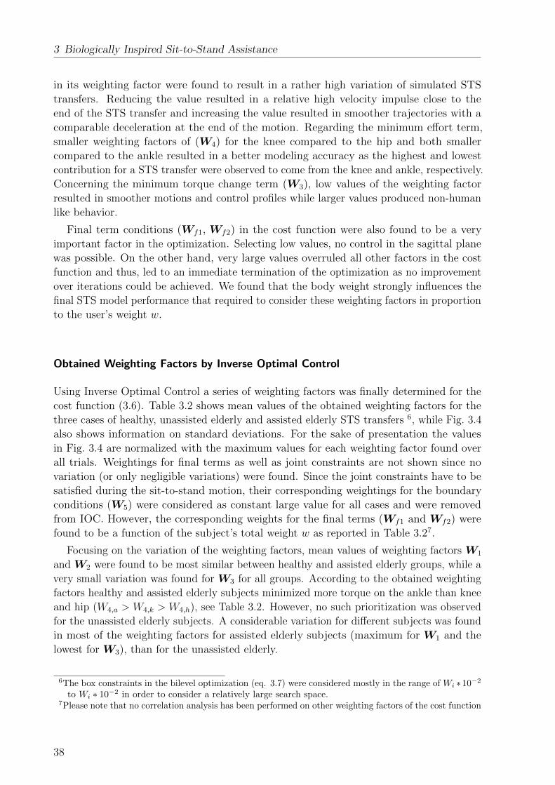
3 Biologically Inspired Sit-to-Stand Assistance
in its weighting factor were found to result in a rather high variation of simulated STS
transfers. Reducing the value resulted in a relative high velocity impulse close to the
end of the STS transfer and increasing the value resulted in smoother trajectories with a
comparable deceleration at the end of the motion. Regarding the minimum effort term,
smaller weighting factors of (W4) for the knee compared to the hip and both smaller
compared to the ankle resulted in a better modeling accuracy as the highest and lowest
contribution for a STS transfer were observed to come from the knee and ankle, respectively.
Concerning the minimum torque change term (W3), low values of the weighting factor
resulted in smoother motions and control profiles while larger values produced non-human
like behavior.
Final term conditions (Wf1, Wf2) in the cost function were also found to be a very
important factor in the optimization. Selecting low values, no control in the sagittal plane
was possible. On the other hand, very large values overruled all other factors in the cost
function and thus, led to an immediate termination of the optimization as no improvement
over iterations could be achieved. We found that the body weight strongly influences the
final STS model performance that required to consider these weighting factors in proportion
to the user’s weight w.
Obtained Weighting Factors by Inverse Optimal Control
Using Inverse Optimal Control a series of weighting factors was finally determined for the
cost function (3.6). Table 3.2 shows mean values of the obtained weighting factors for the
three cases of healthy, unassisted elderly and assisted elderly STS transfers 6, while Fig. 3.4
also shows information on standard deviations. For the sake of presentation the values
in Fig. 3.4 are normalized with the maximum values for each weighting factor found over
all trials. Weightings for final terms as well as joint constraints are not shown since no
variation (or only negligible variations) were found. Since the joint constraints have to be
satisfied during the sit-to-stand motion, their corresponding weightings for the boundary
conditions (W5) were considered as constant large value for all cases and were removed
from IOC. However, the corresponding weights for the final terms (Wf1 and Wf2) were
found to be a function of the subject’s total weight w as reported in Table 3.27.
Focusing on the variation of the weighting factors, mean values of weighting factors W1
and W2 were found to be most similar between healthy and assisted elderly groups, while a
very small variation was found for W3 for all groups. According to the obtained weighting
factors healthy and assisted elderly subjects minimized more torque on the ankle than knee
and hip (W4,a > W4,k > W4,h), see Table 3.2. However, no such prioritization was observed
for the unassisted elderly subjects. A considerable variation for different subjects was found
in most of the weighting factors for assisted elderly subjects (maximum for W1 and the
lowest for W3), than for the unassisted elderly.
6The box constraints in the bilevel optimization (eq. 3.7) were considered mostly in the range of Wi ∗ 10−2
to Wi ∗ 10−2 in order to consider a relatively large search space.7Please note that no correlation analysis has been performed on other weighting factors of the cost function
38

3.2 Validation of STS Model
Table 3.2: Mean value of the cost function weighting factors.
weights healthy unassisted elderly assisted elderly
Wf1 w × 105 w × 105 w × 105
Wf2 w × 102 w × 102 w × 102
W1 188.9 57.2 236.6W2 18.2× diag(1, 1, 1) 1.012× diag(1, 1, 1) 26.21× diag(1, 1, 1)W3 10−3 × diag(1, 1, 1) 10−3 × diag(1, 1, 1) 10−3 × diag(1, 1, 1)W4 10−3 × diag(15, 2, 0.5) 10−3 × diag(60, 6, 3) 10−3 × diag(63, 62, 67)W5 105 105 105
3.2.4 Validation Results
Validation of the finally obtained models was performed by comparing simulations with
mean values of the weighting factors (reported in Table 3.2) and experimental results. The
user’s COM position and joint torques observed during STS transfers and averaged over
the captured trials (5 times for healthy subjects and 3 times for elderly) were chosen for
comparison of simulation and experiments. A first comparison showed that similar STS
strategies were selected by different subjects in each group.
To provide a measure for the overall model accuracy, for all subjects the normalized
integral of the error between experiments and simulation was computed as
ev =
∫|vexp(t)− vsim(t)|dt∫|vexp,max − vexp,min|dt
where vexp and vsim refer to data in experiments and simulation respectively, with vexp,max,
vexp,min the maximum and minimum value of experiments. This error was evaluated over
the x and y components of the COM position (ecomx, ecomy) and the ankle, knee and
hip torques (eτ a, eτ k, eτ h). The obtained results for all 3 cases of healthy, unassisted and
assisted STS transfers are shown in Fig. 3.5. The maximum average error was obtained for
unassisted elderly subjects in the ankle and hip torques. This is mainly due to the fact
that most of the elderly subjects tried to benefit from external assistance using their hand
to initially push their body up in unassisted STS transfers, see Fig. 3.2. This resulted in
a small mismatch between the proposed STS model and experiments. Considering the
complexity of the problem and the simplified assumptions for the human model, the errors
in all 3 studied cases are considerably low and illustrate an overall high agreement of model
and measurements.
As similar results were obtained for the performed repetitions in each group and for the
sake of presentation we only present simulation and measurement trajectories for the COM
position for five repetitions as well as joint angles and joint torques for one repetition in
Fig. 3.6.8 As can be seen all 3 joints as well as COM smoothly converge to their stable final
8Please note that although subjects were asked to minimize variation, still non-negligible differences wereobserved, especially for initial upper body inclination and feet positions.
39
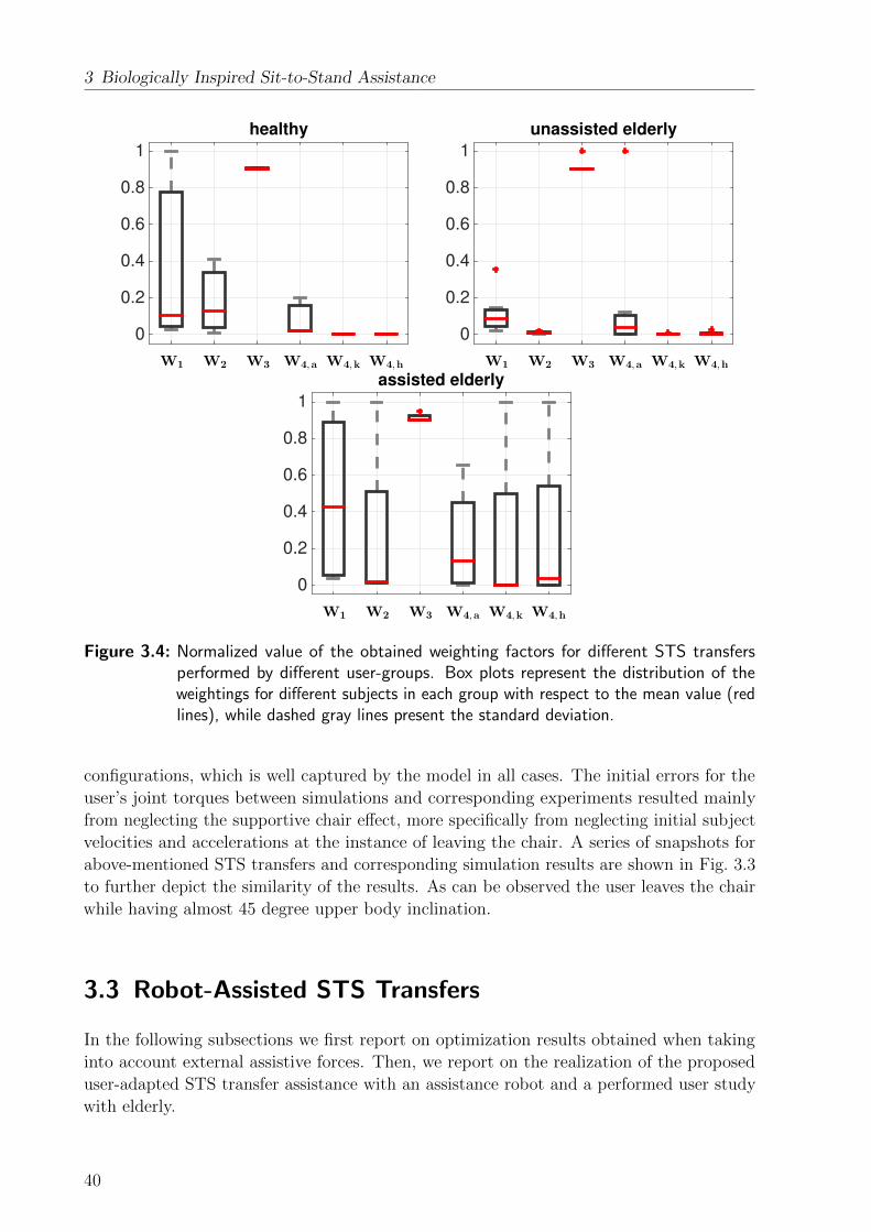
3 Biologically Inspired Sit-to-Stand Assistance
0
0.2
0.4
0.6
0.8
1
W1 W2 W3 W4,a W4,k W4,h
healthy
0
0.2
0.4
0.6
0.8
1
W1 W2 W3 W4,a W4,k W4,h
unassisted elderly
0
0.2
0.4
0.6
0.8
1
W1 W2 W3 W4,a W4,k W4,h
assisted elderly
Figure 3.4: Normalized value of the obtained weighting factors for different STS transfersperformed by different user-groups. Box plots represent the distribution of theweightings for different subjects in each group with respect to the mean value (redlines), while dashed gray lines present the standard deviation.
configurations, which is well captured by the model in all cases. The initial errors for the
user’s joint torques between simulations and corresponding experiments resulted mainly
from neglecting the supportive chair effect, more specifically from neglecting initial subject
velocities and accelerations at the instance of leaving the chair. A series of snapshots for
above-mentioned STS transfers and corresponding simulation results are shown in Fig. 3.3
to further depict the similarity of the results. As can be observed the user leaves the chair
while having almost 45 degree upper body inclination.
3.3 Robot-Assisted STS Transfers
In the following subsections we first report on optimization results obtained when taking
into account external assistive forces. Then, we report on the realization of the proposed
user-adapted STS transfer assistance with an assistance robot and a performed user study
with elderly.
40
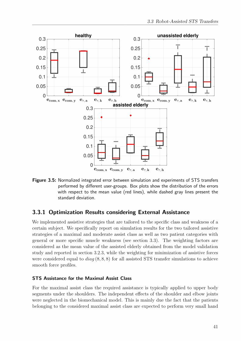
3.3 Robot-Assisted STS Transfers
0
0.05
0.1
0.15
0.2
0.25
0.3
ecom,x ecom,y eτ,a eτ,k eτ,h
healthy
0
0.05
0.1
0.15
0.2
0.25
0.3
ecom,x ecom,y eτ,a eτ,k eτ,h
unassisted elderly
0
0.05
0.1
0.15
0.2
0.25
0.3
ecom,x ecom,y eτ,a eτ,k eτ,h
assisted elderly
Figure 3.5: Normalized integrated error between simulation and experiments of STS transfersperformed by different user-groups. Box plots show the distribution of the errorswith respect to the mean value (red lines), while dashed gray lines present thestandard deviation.
3.3.1 Optimization Results considering External Assistance
We implemented assistive strategies that are tailored to the specific class and weakness of a
certain subject. We specifically report on simulation results for the two tailored assistive
strategies of a maximal and moderate assist class as well as two patient categories with
general or more specific muscle weakness (see section 3.3). The weighting factors are
considered as the mean value of the assisted elderly obtained from the model validation
study and reported in section 3.2.3, while the weighting for minimization of assistive forces
were considered equal to diag (8, 8, 8) for all assisted STS transfer simulations to achieve
smooth force profiles.
STS Assistance for the Maximal Assist Class
For the maximal assist class the required assistance is typically applied to upper body
segments under the shoulders. The independent effects of the shoulder and elbow joints
were neglected in the biomechanical model. This is mainly due the fact that the patients
belonging to the considered maximal assist class are expected to perform very small hand
41

3 Biologically Inspired Sit-to-Stand Assistance
horizontal displacement [m]-0.15 -0.1 -0.05 0 0.05 0.1
vert
ical dis
pla
cem
ent [m
]
0.75
0.8
0.85
0.9
0.95
1
1.05
1.1
1.15
1.2
[1]
[2]
[3]
[4]
[5]
COM position
time [s]0 0.5 1 1.5
-2
-1.5
-1
-0.5
0
0.5
1
1.5
2joint angle [rad]
anklekneehip
time [s]0 0.5 1 1.5
-100
-50
0
50
100
150joint torque [N.m]
anklekneehip
Figure 3.6: Simulation and experimental results of the human COM position (left), joint angles(mid), and joint torques (right) during STS transfers. Left: trajectories of theuser’s COM from five STS transfer repetitions (solid lines) and correspondingsimulation result (dashed red). Middle, right: experimental results of the jointangles and torques (solid line) and simulation results (dashed).
x [m]-0.35 -0.3 -0.25 -0.2
y [m
]
0.80.9
11.11.2
COM position
time [s]0 1 2
-2
-1
0
1
2joint angle [rad]
anklekneehip
time [s]0 1 2
-500
50100150
assistive forceFx [N]Fy [N]Mz [N.m]
time [s]0 1 2
-50
0
50joint torque [N.m]
anklekneehip
−0.3 −0.25 −0.2 −0.150.8
1
1.2COM position
x [m]
y [m
]
0 1 2−2
0
2joint position [rad]
time [s]
anklekneehip
0 1 2−500
50100150
time [s]
assistive force
Fx [N]Fy [N]Mz [N.m][Nm]
0 1 2−50
0
50
100
time [s]
joint torque [N.m]
anklekneehip
−0.3 −0.25 −0.2 −0.150.8
1
1.2
COM position
x [m]
y [m
]
0 1 2−2
0
2joint position [rad]
time [s]
anklekneehip
0 1 2−500
50100150
time [s]
assistive force
Fx [N]Fy [N]Mz [N.m][Nm]
0 1 2−50
0
50
time [s]
joint torque [N.m]
anklekneehip
−0.3 −0.25 −0.2 −0.150.8
1
1.2
COM position
x [m]
y [m
]
0 1 2−2
0
2joint position [rad]
time [s]
anklekneehip
0 1 2−50
0
50
time [s]
assistive force
Fx [N]Fy [N]Mz [N.m][Nm]
0 1 2−50
0
50
100
time [s]
joint torque [N.m]
anklekneehip
Figure 3.7: Columns from left to right: simulation results of the human COM positions, jointpositions, external assistive forces and moment, and joint torques during STStransfers for patients belong to the class of maximal assistance and having equalweakness in all joints (first row) and weakness in specific joints (second row), aswell as for patients belong to the class of moderate assistance and having equalweakness in all joints (third row) and weakness in specific joints (fourth row).
42

3.3 Robot-Assisted STS Transfers
motions during a STS transfer. However, the inertia effects of the hands are still considered
in the upper body dynamics. We restricted the shank motion by considering a lower range
of motion for ankle joint (3.6) to mimic the influence of locking the patient’s knees and feet
during STS transfer.
Considering the minimum torques needed to rise successfully without help, see [124], joint
torque constraints (τankle < 75, τknee < 75, τhip < 25) were assumed to simulate patients
of case a and (τankle < 40, τknee < 40, τhip < 40) for case b, respectively. We considered
more than 50% weakness for a person with body measurements similar to subject S1. We
also activated the most effective interactive force components in the STS transfer model,
namely vertical and horizontal external force components (Fx, Fy) as well as the angular
momentum (Mz). Figure 3.7 shows obtained trajectories of the assistive force/moment
profiles to be applied to the user as well as the user’s COM, joint angles and joint torques.
As can be observed human weakness is compensated through proper external assistance as
the STS transfer is smoothly accomplished while the human joint torque remained lower
than the considered user’s capability.
STS Assistance for the Moderate Assist Class
For the moderate assist class we assumed that the patient is able to rigidly grasp a robotic
device that assists in STS transfers. Thus, also the human arm has been considered in
the biomechanical model. Higher joint torque limits compared to the maximum assist
class and the two sorts of weaknesses were set (τankle < 100, τknee < 100, τhip < 50) for case
a and (τankle < 55, τknee < 55, τhip < 55) for case b. Required supportive force/momentum
profiles as well as the obtained user’s COM, joint positions and torques during the STS
accomplishment are shown in Fig. 3.7. As expected, the required external supportive
force/moments are reduced in comparison to the maximal assist class while again the
human weakness is well compensated.
3.3.2 User Study
An intensive evaluation by 33 elderly subjects was performed to assess the effectiveness of
the proposed optimal STS transfer assistance. Thirty women and three men participated in
the evaluation which took place for six weeks (from Oct. to Dec. 2014), in the Agaplesion
Bethanien Hospital/Geriatric Centre of the University of Heidelberg. The average age
of participants was 84.5 ±5.0, ranging from 74 to 94 years old. Subjects had on average
moderate stage impairment in cognitive and motor status (MMSE score: 24.9 ±3.9; 5-chair
stand: 19.6 ±3.9s; gait speed 0.47 ±0.13). Moreover, 64% of participants experienced
at least one fall within the past 12 months. All the users used normal walkers in their
daily life. The experiments were performed with the ethical approval of the Ethics review
committee (Ethikkommission der Medizinischen Fakultat Hei-delberg, Alte Glockengießerei
11/1, 69115 Heidelberg, Germany).
43
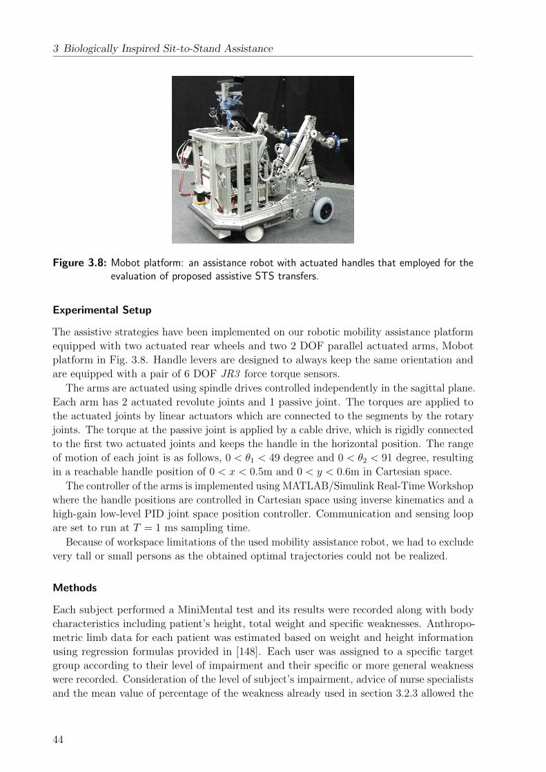
3 Biologically Inspired Sit-to-Stand Assistance
Figure 3.8: Mobot platform: an assistance robot with actuated handles that employed for theevaluation of proposed assistive STS transfers.
Experimental Setup
The assistive strategies have been implemented on our robotic mobility assistance platform
equipped with two actuated rear wheels and two 2 DOF parallel actuated arms, Mobot
platform in Fig. 3.8. Handle levers are designed to always keep the same orientation and
are equipped with a pair of 6 DOF JR3 force torque sensors.
The arms are actuated using spindle drives controlled independently in the sagittal plane.
Each arm has 2 actuated revolute joints and 1 passive joint. The torques are applied to
the actuated joints by linear actuators which are connected to the segments by the rotary
joints. The torque at the passive joint is applied by a cable drive, which is rigidly connected
to the first two actuated joints and keeps the handle in the horizontal position. The range
of motion of each joint is as follows, 0 < θ1 < 49 degree and 0 < θ2 < 91 degree, resulting
in a reachable handle position of 0 < x < 0.5m and 0 < y < 0.6m in Cartesian space.
The controller of the arms is implemented using MATLAB/Simulink Real-Time Workshop
where the handle positions are controlled in Cartesian space using inverse kinematics and a
high-gain low-level PID joint space position controller. Communication and sensing loop
are set to run at T = 1 ms sampling time.
Because of workspace limitations of the used mobility assistance robot, we had to exclude
very tall or small persons as the obtained optimal trajectories could not be realized.
Methods
Each subject performed a MiniMental test and its results were recorded along with body
characteristics including patient’s height, total weight and specific weaknesses. Anthropo-
metric limb data for each patient was estimated based on weight and height information
using regression formulas provided in [148]. Each user was assigned to a specific target
group according to their level of impairment and their specific or more general weakness
were recorded. Consideration of the level of subject’s impairment, advice of nurse specialists
and the mean value of percentage of the weakness already used in section 3.2.3 allowed the
44

3.3 Robot-Assisted STS Transfers
selection of specific joint torque limits for the optimization. Finally, optimizations were
performed to derive user-specific optimal robot handle trajectories taking the aforemen-
tioned joint torque limits into account. Because of robot workspace limitations, initial and
final hand configurations were considered within the robot workspace to achieve optimal
trajectories realizable with our assistance robot. The initial hand position was selected
as close as possible to the subject hip sitting on a chair. An example of the achieved
individualized robot handle trajectories is shown in Fig. 3.9.
Figure 3.9: An example of the achieved individualized robot handle trajectories (left: handleposition, right: handle velocities).
During the experiments the chair height was adjusted to the user’s knee height. Before
testing the robot STS transfer assistance, the ability of participants to perform unassisted
STS transfers was assessed. The participants were instructed to stand up without receiving
any support neither from the assistance robot, nor from the nurse-specialist supervising
the experiments. In order to standardize experiments, each subject was orally instructed
how to use the assistance robot, where to sit and how to keep the feet position. Then, the
assistance robot was placed in front of the patient and the robot handles were brought to
the initial configuration for the STS task. The subject was asked to grip the robot handles
and to trigger the robot controller by applying a rather small downward force, whenever
they felt ready for the STS transfer. Each subject performed 5 STS transfers with the help
of the assistance robot considering pauses to avoid exhaustion. After finishing all 5 trials
participants were asked to fill a questionnaire.
Figure 3.10: Snapshots taken during the evaluation of the STS transfer assistance.
45

3 Biologically Inspired Sit-to-Stand Assistance
Results
Figure 3.10 shows a sequence of the STS transfer assistance provided by the robot to an
elderly subject. In total 165 STS trials were recorded from 33 participants. Apart from the
results of the questionnaire (which will be reported in a different place reporting the clinical
perspective), two performance metrics were considered in order to verify the effectiveness
of the proposed STS transfer support: STS transfer success rates and similarity of the
assistive force profiles in simulation and experiments.su
cce
ss r
ate
[%
]
0
10
20
30
40
50
60
70
80
90
100
unassisted1st 2nd 3th 4th 5th
55%
85%88%
94%
100% 100%
optimally assisted
Figure 3.11: Success rate of STS transfers.
All participants were able to stand up from the chair with the help of the assistance
robot at least three out of five times, where all participants successfully achieved a standing
position within the 4th and 5th trial. Figure 3.11 shows the average success rate recorded
for all patients per trials. Across all participants and trials an average success rate of 93.3%
was achieved, while a success rate of 54.5% was achieved for the preliminary test assessing
the STS transfer ability without support. Subjects became quickly familiar with the robot
and fast motor learning took place as the success rate increased quickly with trials. The
100% success rate for the fourth and fifth trial shows a great success in providing robotic
STS transfer assistance.
Apart from the success rate for STS transfers, we aimed to compare the similarity of
interaction forces between human and robot obtained in simulation and experiments. The
forces and moments measured at each robot handles were transferred and summed as
follows to define the total interaction forces and moments (Ftot and Ttot) provided to the
human,
Ttot = hl × Fl + hr × Fr, (3.8)
Ftot = Fl + Fr
where hi i ∈ (l, r) are the distance between the contact points (robot handles) and the
center of robot handles. We mainly compare the horizontal and vertical components of the
obtained force trajectories as well as the component of the moment orthogonal to the plane
46

3.4 Summary and Discussion
time [s]0 0.5 1 1.5 2 2.5 3
-60
-40
-20
0
20
40
60
80
100
120
140assistive force
Fx [N]Fy [N]Mz [Nm]
time [s]0 0.5 1 1.5 2 2.5 3
-100
-50
0
50
100
150
200assistive force
Fx [N]Fy [N]Mz [Nm]
Figure 3.12: Comparison of simulation and experimental force trajectories for two elderlysubjects able to fully stretch their body in the final standing configuration (left)and two elderly subjects not able to fully stretch their body in the final standingconfiguration (right). Solid and dotted lines are obtained measurements of thefourth and fifth STS transfer trials, while dashed lines are the expected forcetrajectories obtained by simulation.
of the force axis. Although for many of the patients a good similarity has been obtained,
see e.g. Fig. 3.12 (left), some of the subjects could not fully stretch their body in the final
configuration and therefore a considerable high amount of assistive forces was required
while standing, see e.g. Fig. 3.12 (left). As this latter case was not considered in our model,
clear mismatches between measurements and simulation can be observed. To incorporate
this effect joint limits need to be adjusted. Further, asymmetric motions as observed for
patients with one-sided impairments can not be properly replicated by our 2D model and
require an extension to 3 dimensions.
After completion of all 5 STS transfers, the subjective user’s perception was evaluated
by means of a questionnaire adopted from [149]. High overall satisfaction with the optimal
STS assistance system was observed. Details on this subjective evaluation though will be
reported in a different place addressing the clinical perspective.
3.4 Summary and Discussion
Understanding the human STS motions allows us to control assistance robots in a
biologically-inspired manner resulting in an intuitive and natural behavior for the coupled
system of human and assistance robot. This way of control design for assistance robots has
received very little attention, especially when considering STS transfer assistance.
The main contribution of this chapter is to propose a mathematical model for unassisted
and assisted human STS transfers, to determine underlying principles and to further use
these findings in the derivation of optimal assistive strategies. This chapter presented an
optimal feedback control formulation for the modeling of assisted and unassisted human
STS transfers. Compared to previous work based on SQP approaches, the presented
47

3 Biologically Inspired Sit-to-Stand Assistance
optimization problem is based on DDP that has been shown as a powerful tool to study
biological movements. It allows us to obtain an optimal solution with respect to a defined
cost function and considers the nonlinearity of human biomechanics as well as physical
constraints, which are naturally incorporated into the optimization framework. It further
shows the potential for future online implementations.
This chapter provided evidence that natural STS transfers could be achieved with the
help of a cost function that linearly combines a series of criteria and finds a compromise
between task end-point accuracy, human balance, energy consumption as well as smoothness
of the motion and takes further human biomechanical control constraints into account.
While we have employed the above-mentioned combination of criteria, future work can
investigate other possible criteria especially considering subjects with different limitations
or weaknesses. Moreover, possible adaptation of the weighting factors for each criteria over
time can be investigated. This may help developing more sophisticated assistance systems,
for example, to create a rehabilitation program.
The model was extended with external forces and torques and optimal assistive STS
transfer strategies were determined considering two types of assistance classes and weak-
nesses. The resulting optimal assistive trajectories were calculated and implemented on a
robotic mobility assistant. The assistive STS transfer approach was finally evaluated by 33
elderly subjects performing 165 trials. Results show a high users satisfaction as well as a
100% success rate for all participants in the fourth and fifth trial.
Further research of the presented methodology should look at the extension of the STS
model by inclusion of the chair support forces, which were neglected in this chapter but
will require switching the model during optimization. Moreover, online implementation of
the optimal control approach for assisted sit-to-stand transfers can be an ultimate target.
This is particularly important since offline computations are based on assumptions (such as
human’s initial joint angles) that may not correspond to the real-world situations. Apart
from overcoming the latter problem, online implementation can also simplify the two steps
of firstly calculating the assistance trajectories offline, and then implementing them in the
real robot in one step which would be a more practical solution indeed.
The approach presented in this chapter shows how human motor control models can
be employed to develop optimal assistive strategies. This human-inspired control design
approach is continued in the next chapter where human-decision making mechanisms
embedded into the control design of MARs to realize a user and environment-adaptive
walking assistance are investigated.
48

4 User and Environment-Adaptive WalkingAssistance
The second considered mode of operation in this thesis is walking. A sufficient walking
performance that allows performing physical daily activities is a critical requirement for
maintaining mobility and vitality, especially for elderly people and patients. Changes due
to aging or disease may result in the limitation of human motor performance, sensory
capabilities and cognitive functions, and thus reduce the ability to perform daily walking.
This often leads to less autonomy and a decreased quality of life and self-esteem. Therefore, it
is important that the elderly and patients are supported by MARs during walking. However,
this comes with different challenges such as safety and user and environment-adaptive
shared control.
A major challenge in the controller design of MARs during walking is how to adapt the
provided assistance depending on the actual context of both the human and environment.
An assistance robot under direct user control can have difficulties guaranteeing acceptable
performance and safety due to cognitive, sensorial and physical weaknesses as a result
of target users being elderly or disabled people. On the other hand, a fully autonomous
system that ignores the user’s intention can result in user dissatisfaction and dangerous
situations in the event of human and robot disagreement. Therefore, a shared control
approach allowing human and robot to share the control over resulting actions is typically
employed.
Shared control has been studied for different applications of human-machine interaction:
For example [150–154] investigated shared control for teleoperation, space and aviation
systems, [155–158] explored similar principles for surgery applications, while [159] and [160]
report on shared control for powered wheelchairs.
In literature most adaptive shared control mechanisms attempt to tune the level of
assistance to improve metrics related to the task. Thus, an inherent difficulty lies in
deciding on suitable metrics and adaptation strategies such that the overall robot assistance
results in a natural behavior to the user. In this context natural refers to an intuitive
cooperative control scheme that considers human and robot to collaborate as peers, meaning
that the robot is allowed to make its own decisions to online adjust the level of assistance
taking current and past information on the user and environment into account. We believe
that an intuitive and natural behavior can be achieved if the robot can decide on the
provided level of assistance in a similar way to humans. Thus, for the first time this chapter
formulates the problem of the allocation of control authority as a decision-making problem
and employs human-inspired decision-making models. We use the Drift-Diffusion (DD)
model, firstly proposed by [161], that describes the decision-making mechanism in humans
as a process in which decisions are based on past decisions and the decision criteria are
continuously adjusted in order to maximize the reward obtained throughout task execution.
Following the principles of the DD model, we propose a mathematical formulation for
49
4 User and Environment-Adaptive Walking Assistance
an integrated control architecture to adapt the parameters of the shared control system
of a rollator-type MAR. The proposed architecture allows for intuitive adaptation of the
short-term a) cognitive assistance helping the user to follow a desired path towards a
predefined destination, the robot b) sensorial assistance to avoid collisions with obstacles
and to allow an intentional approach of them, and the more long-term adaptation of
the robot c) physical assistance based on measured user’s performance and fatigue. We
illustrate the effectiveness of the proposed architecture in experiments and evaluate its
performance by conducting a user-study with elderly subjects. Obtained results indicate an
acceptable user’s satisfaction and show a general high potential of the proposed adaptive
shared control architecture for MARs.
This chapter is organized as follows: section 4.1 reviews related work. Section 4.2
introduces the MAR and the implemented admittance control approach. The integrated
adaptive shared control architecture is presented in section 4.3, while section 4.4 provides
details on the implementation of the adaptation policies for the sensorial, cognitive and
physical assistance. Finally, section 4.5 discusses the experimental setup and reports on
technical validation experiments and the performed user-study with elderly users.
4.1 Related Work
While chapter 2 provided a general review of found approaches adopted to realize walking
assistance, the following section focuses specifically on reviewing approaches of adaptive
shared control of MARs as well as decision-making in humans and related models.
4.1.1 Adaptive Shared Control for MARs
Variable admittance control is the most common control scheme in MARs. An admittance
model defines the sensitivity of the device to the applied human forces according to a
specified desired mass and damping that should be rendered by the device. The behavior
of the system can be modified by adapting this admittance, or by manipulation of the
force applied by the user. In [17, 22, 53] the authors for example improve maneuverability
by applying a transformation on the user’s force that allows to online modify the center
of rotation of the mobility assistant. In [12, 14, 110] authors propose to include also a
braking force to the admittance law and to achieve the robot desired behavior such as
fall prevention, gravity compensation on slopes or step avoidance by proper activation of
the brakes. Different environment-adaptive approaches, mainly based on the inclusion of
additional forces/torques to the admittance model for obstacle avoidance and goal-seeking
(generated based on environment information) can be found in [11, 15, 19, 20, 54, 92, 110].
These approaches can result in an active robot behavior which can lead to dangerous
situations, for example in case the human releases the handles and the robot continuous to
move or the human plans to walk on a straight path, while the system accidently turns to
circumvent an obstacle.
Only few works consider the history of the human performance during the interaction with
the robot in the adaptation law of the admittance controller. In [45] the author proposes
a cost function with forgetting factor evaluating the user’s performance by combining
50
4.1 Related Work
multiple criteria like the proximity to obstacles, the deviation from the planned trajectory
and human stability criteria. This allows to realize an adaptive shared control with varying
force gains, which provides more authority to the human or the robot assistant depending
on the accumulated human performance. Similarly, in [25] the authors propose to shift
authority from the human user to the robotic system or vice versa depending on the specific
context and logical rules allowing e.g. for the implementation of a no assist mode, an
assist mode (human and robot share the execution of the task), a safety mode (robot acts
fully autonomous) or an override mode (robot is under full control of the human). In
[162, 163] again a logical rule-based method is proposed that evaluates the interaction force
to estimate the human intentional direction which is defined as “the direction into which a
person intends to move” and then select the admittance parameters among some defined
values. Different admittance parameters are studied to provide the user a comfortable
feeling while walking and to avoid manoeuvres in unintended directions.
Apart from the use of variable admittance control, few other approaches exist that
address the problem of shared control. A Bayesian network approach that combines sensor
information with user’s inputs (read by an interface with three buttons for moving forward,
turn left or right) and that activates respective autonomous robot behavior is proposed
in [97]. An autonomous path planning and obstacle avoidance approach is discussed in
[33, 34, 94, 95] that lets the user decide on the robot velocity leaving partial authority of
modifying the path with the user. The author employs advanced methods for dynamic path
planning (e.g. elastic bands [112]) to allow for dynamic obstacle avoidance and smooth
path planning and modifications according to user’s inputs. In [54] three robot guiding
behaviours including obstacle avoidance, wall following, and goal seeking are designed for
an omni-directional mobile robot by evaluating laser sensor data and by fusing these three
behaviors by means of a Fuzzy Kohonen Clustering Network. In [31] the authors use forces
and moments a user applies to a walker’s handle in addition to information on the local
environment and the walker’s state to derive the most likely human intention, respectively
path to follow. Depending on the identified intention, the angle of the robot front wheel
is set by the mobility assistant, leaving the user the freedom to decide on the velocity to
move on the identified path. Finally, a switching controller to avoid human forward fall
and human-robot collision is proposed in [101].
Summarizing, although a series of adaptive shared control approaches for mobility
assistance robots were studied in literature as listed above, to the best of the authors
knowledge none of the aforementioned approaches used human-inspired decision-making
models to define adaptation policies for the provided level of assistance, which is expected
to result in a natural and safe human-robot interaction. Thus, for the first time we study
human decision-making models as mechanism to gain-schedule low-level control parameters
and with this to vary the level of assistance provided and evaluate the effectiveness of this
approach for real end-users.
4.1.2 Human Decision-Making Models
In cognitive science, human decision-making has been widely studied in so called two-
alternative forced-choice (TAFC) tasks. TAFC tasks require a human to make a sequence
of choices between two predefined alternatives. After every choice, the subject is given a
51

4 User and Environment-Adaptive Walking Assistance
reward based on the current choice and the previous N choices. The subject’s goal is to
maximize the accumulated reward over a sequence of choices. TAFC tasks were used to
study optimal decision strategies, see [161, 164], or sub-optimal strategies, see [165, 166]. In
human subject experiments, it was observed that for a majority of human subjects working
with particular reward structures, decisions are centered around particular points, termed
matching points, where the reward return curves for the two options cross.
Mathematical investigations focusing on potential underlying mechanisms of human
decision-making have involved among others Markov decision processes (MDP) and drift-
diffusion (DD) models. Authors in [167] consider TAFC tasks and a DD model together as
a Markov process and show that, under certain assumptions, the DD model analytically
exhibits matching behavior as observed in human subjects. In [168], convergence to a
matching point is proven for a particular task called the matching-shoulders-type task and
using the DD model with a time decay extension. In [164] and [169], a combination of a
DD model and MDP is used to address empirical and analytical effects of social context
(decisions and rewards of other people) on decision-making.
Although several extensions to the concept of decision-making based on the DD model
in TAFC tasks exist, see for example [170, 171], its application to assistance robotics has
not received lots of attention. In this work we extend our previous work [172] and explore
the applicability of the DD model to MARs supporting elderly and patients.
4.2 MAR Low-Level Control
4.2.1 System Description
We consider the rollator in Fig. 3.8 that is of active and non-holonomic type, meaning
that the translational motion of the robot along the heading direction as well as rotational
motion along its center of rotation are possible, while motions in lateral direction are
restricted. With reference to Fig. 4.1, the non-holonomic constraint is given by
xr sin θr − yr cos θr = 0,
and therefore the kinematic model can be written as follows,
q =
xryrθr
=
cosθr 0
sinθr 0
0 1
[vω
]= Ju, (4.1)
where v and ω are two available control inputs for the linear and angular velocities around
the vertical axis and q = [xr, yr, θr]T the states of the robot.
4.2.2 Admittance Control
Two force/torque sensors mounted at the handles of the rollator are used to drive the
differential drive MAR. Force components along and around the heading direction are used
52
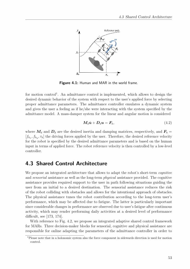
4.3 Shared Control Architecture
Figure 4.1: Human and MAR in the world frame.
for motion control1. An admittance control is implemented, which allows to design the
desired dynamic behavior of the system with respect to the user’s applied force by selecting
proper admittance parameters. The admittance controller emulates a dynamic system
and gives the user a feeling as if he/she were interacting with the system specified by the
admittance model. A mass-damper system for the linear and angular motion is considered
Mdu+Ddu = Fh, (4.2)
where Md and Dd are the desired inertia and damping matrices, respectively, and Fh =
[fhx , fhy , τh] the driving forces applied by the user. Therefore, the desired reference velocity
for the robot is specified by the desired admittance parameters and is based on the human
input in terms of applied force. The robot reference velocity is then controlled by a low-level
controller.
4.3 Shared Control Architecture
We propose an integrated architecture that allows to adapt the robot’s short-term cognitive
and sensorial assistance as well as the long-term physical assistance provided. The cognitive
assistance provides required support to the user in path following situations guiding the
user from an initial to a desired destination. The sensorial assistance reduces the risk
of the robot colliding with obstacles and allows for the intentional approach of obstacles.
The physical assistance tunes the robot contribution according to the long-term user’s
performance, which may be affected due to fatigue. The latter is particularly important
since considerable changes in performance are observed due to user’s fatigue after continuous
activity, which may render performing daily activities at a desired level of performance
difficult, see [173, 174].
With reference to Fig. 4.2, we propose an integrated adaptive shared control framework
for MARs. Three decision-maker blocks for sensorial, cognitive and physical assistance are
responsible for online adapting the parameters of the admittance controller in order to
1Please note that in a holonomic system also the force component in sidewards direction is used for motioncontrol.
53

4 User and Environment-Adaptive Walking Assistance
Figure 4.2: MAR adaptive shared control architecture.
achieve the desired system behavior. The Decision on cognitive assistance block evaluates
the planned path towards the goal which is generated by the path planner block, the human
navigational intention in form of force and torque applied to the robot handles as well as the
actual human performance. The Decision on sensorial assistance block uses human input
and the information provided by the Environment state block, which provides information
on the position of obstacles around the robot. Finally, the Decision on physical assistance
block processes all inputs and adjusts the level of active support provided accordingly.
The concept of the robot assistance is implemented by manipulating the admittance
control parameters. We decompose and extend the admittance controller (4.2) as follows:
mxv + dxv = fhx , (4.3)
Iθω + dθω = k1τh + k2τassis, (4.4)
k1 + k2 = 1, (4.5)
where the parameters mx, dθ and fhx are the mass, damping and human force components
along the heading direction of the robot (in alignment with the unitary vector x of the
robot in Fig. 4.1). The variables Iθ, dθ and τh are the inertia, damping and human torque
components. The parameters dx, dθ and k2 are tuned to satisfy the aforementioned sensorial,
cognitive and physical assistance. Increasing the value of dx decelerates the robot motion
in heading direction and knowing that the robot is of non-holonomic nature this effect can
be used for the purpose of robot sensorial assistance. Manipulation of dθ influences the
felt resistance when aiming to change the robot orientation and thus, can help preventing
deviations from the desired path towards the destination. Finally, an increase of k2 increases
the robot active contribution to the control of the orientation of the robot. This effect is
used for varying the physical assistance provided by the robot. The adaptation of the dxand dθ parameters results in a passive and thus, intrinsically safe support strategy. The
advantage of active support is used to tune the parameter k2, whenever the passive support
strategy alone cannot provide the desired system behavior, e.g. when the user is exhausted
and can hardly guide the robot towards his/her desired destination.
The decision-making systems that decide on the specific tuning of these parameters are
discussed in the following sections.
54

4.4 Decision-Making for MARs
4.4 Decision-Making for MARs
The individual decision-making policies that decide on the specific level of robot assistance
provided are formulated based on the DD model to achieve an intuitive online adaptation
of the robot assistance. In the following sections, we first introduce the DD model, and
then detail its application for designing an adaptive robot assistance for a MAR.
4.4.1 Decision-Making Principle based on DD Model
In a two-alternative forced-choice (TAFC) task a human has to take a decision between
two alternative choices and is asked to continuously choose between them. Each choice is
associated with a specific reward. The human not knowing about the underlying reward
structures typically explores the options and gradually optimizes the overall intake. Different
reward structures have been proposed in literature to study human decision-making behavior.
In this thesis, we mainly focus on the matching shoulder reward structure. The matching
shoulder structure consists of two reward functions with inverse relationships as encountered
for example whenever two goals are conflicting and a decision has to be taken for either
improving the one or the other. The specific form of the two crossing reward functions
is a design factor and allows to program different kind of behaviors allowing to favor one
goal over another in some situations, while favoring the other in other situations. Thus, in
general the matching shoulder structure consists of two intersecting curves that diminish
with increasing/decreasing performance. Consider pA and pB human performance measures
associated with the choices A and B and the associated rewards rA and rB. Further, and
only assumed in the context of this thesis, the general relationship of a reward r and a
performance measure p should be given by:
rz = kz(pz − poffset,z)nz + r0,z, (4.6)
where poffset,z, r0,z, kz, and nz are the user and task-defined tunable variables for each
specific reward structure (z ∈ A, B).
The Drift Diffusion (DD) model has proven to implement the optimal mechanism for
TAFC decision-making tasks and accounts for an impressive amount of behavioral and
neuroscientific data. The DD model characteristic can be formulated as soft-max model
firstly introduced by [161] to describe human decision-making in TAFC tasks. The soft-max
model as a main component in human decision-making processes was also shown by [175]
and formulated using a sigmoidal function
PA(t+ 1) =1
1 + exp−µ(wA(t)−wB(t)). (4.7)
According to this model, the probability of the human preference for choice A at time
t+1 is PA(t+1) which is computed using (4.7), where wA(t) and wB(t) are the accumulated
evidences for choosing option A or B, respectively. The parameter µ is used to manipulate
the slope of the sigmoid function, and therefore the level of certainty in making a decision.
The values wA(t) and wB(t) are updated with the help of a learning rule. Authors in
[176] have proposed a discrete-time linear update rule. Considering the decision set z ∈
55

4 User and Environment-Adaptive Walking Assistance
[A,B] at each time t, then
wz(t+ T ) = (1− λ)wz(t) + λrz(t) (4.8)
where z is the decision just made, rz(t) the obtained reward for z, λ ∈ [0 1] a forgetting
factor and T the sample time in the system. We consider the same initial value for the
weightings wz which implies no preference for each of the two choices.
In the following sections we employ the DDM as a key element for the gain-scheduling of
low-level control parameters resulting in varying levels of physical, sensorial and cognitive
assistance. Doing so, the problem of fulfilling two conflicting goals is formulated for each
type of assistance studied. Then, associated performance metrics are defined and the
corresponding matching shoulder reward structures are introduced. Next, the level of the
provided assistance is decided upon by evaluating the DDM (4.7), which finally determines
which of the two conflicting goals should be prioritized according to the accumulated
evidence to improve the overall intake. Finally, a linear homotopy is applied for gain
scheduling respective low-level control parameters c between a pre-defined minimum and
maximum value based on the determined probabilities for deciding on either of the two
choices:
c(t) = PA(t+ 1)cmin + (1− PA(t+ 1))cmax. (4.9)
4.4.2 Decision on Cognitive Assistance
In this section, we formulate the problem of providing adaptive, passive cognitive assistance
as a human decision-making problem. We employ the DD model for gain-scheduling of the
low-level control parameter dθ to online adjust the level of the provided robot cognitive
assistance.
Problem Formulation
An important functionality of the MAR is guiding the user from an initial to a target
destination, especially for users who are cognitively impaired and have thus, difficulties in
locating themselves and finding their way. An ideal robot assistance makes the user feel
comfortable by giving him/her enough control over the platform, while the user is safely
guided towards the desired destination. In particular, we aim at improving human-robot
agreement by providing the user enough freedom in controlling the platform as long as
the deviation from the desired path stays within acceptable limits and at shifting priority
towards improving task performance by reducing the human control authority in case
the task deviation is slowly approaching its allowed maximum, but the user performs no
proper reaction to prevent this. This trade-off is formulated as decision-making problem.
The assistance is realized by a passive guidance that prevents movements in directions
perpendicular to the desired path and giving the user’s freedom to control the robot when
moving along the reference path.
Consider a task of path following from an initial to a final location where the desired
path is known for the robot assistant. The human forces (fh = [fhx , fhy ]T ), represented by
the linear components (two first entries) of Fh in (4.2) are used to control the linear robot
56

4.4 Decision-Making for MARs
motion along the robot reference frame. They can be split into two main components, the
human force along the reference path (f‖) and perpendicular to it (f⊥). With reference to
Fig. 4.1, the magnitudes of these forces are given as follows,
f‖ =‖ fh ‖ cos(θe), f⊥ =‖ fh ‖ sin(θe), (4.10)
where θe = θref − θr and θref is the desired orientation between the reference path and the
global x-axis.
We believe that the proper control of the robot orientation error is satisfactory for the
purpose of providing cognitive assistance. To ensure a safe robot behavior, we propose a
passive assistance by adapting the damping parameter dθ and thus, indirect manipulation of
the robot angular velocity and orientation error while giving the user the freedom to move
freely along the path. This reduces the problem to the adaptation of only one parameter,
namely the damping parameter dθ. The adaptation law for this parameter is formulated as
a decision-making problem using the DD model.
Performance Measures
Task performance is measured using the rotational and translational tracking error formu-
lated with respect to the desired path over an observation windows NC
pT,C =
∑NC
i=1 kC,eei + kC,θeθeiNC ·max(kC,ee+ kC,θeθe)
, (4.11)
where the subscript i refers to the value of the variable at the sample i and e is the robot
position error given by
e =√
(xref − xr)2 + (yref − yr)2, (4.12)
and pT,C means the normalized task performance computed over NC samples, and kC,eand kC,θe are two user-defined factors distributing the weightings between orientation and
translation. The max value is initialized with the maximum acceptable error with respect
to the task and is updated if a larger value is observed during the interaction process.
Disagreement is assumed to occur when the user and robot assistant apply forces in
opposite directions leading to so called internal forces. These internal forces provide
important information on haptic interaction, see e.g. [177]. Minimizing disagreement can
enhance the quality of human-robot interaction as the robot then behaves according to
human expectations. Considering the task of providing cognitive assistance described in
the previous section, we define the internal moment τint as follows
τint =
τh + lff⊥ sign(τh + lff⊥) 6= sign(τrobot)∧|τh + lff⊥| ≤ |τrobot|,
−τrobot sign(τh + lff⊥) 6= sign(τrobot)∧|τh + lff⊥| > |τrobot|,
0 otherwise,
(4.13)
57
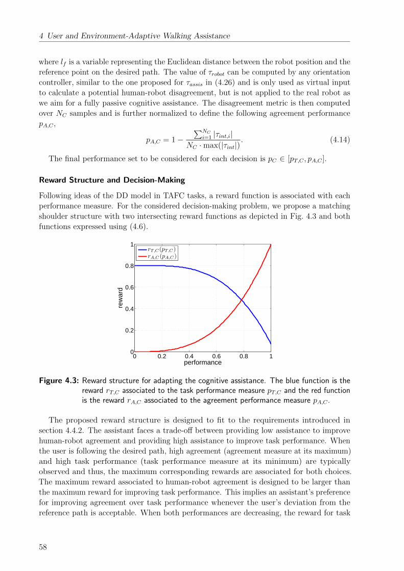
4 User and Environment-Adaptive Walking Assistance
where lf is a variable representing the Euclidean distance between the robot position and the
reference point on the desired path. The value of τrobot can be computed by any orientation
controller, similar to the one proposed for τassis in (4.26) and is only used as virtual input
to calculate a potential human-robot disagreement, but is not applied to the real robot as
we aim for a fully passive cognitive assistance. The disagreement metric is then computed
over NC samples and is further normalized to define the following agreement performance
pA,C ,
pA,C = 1−∑NC
i=1 |τint,i|NC ·max(|τint|)
. (4.14)
The final performance set to be considered for each decision is pC ∈ [pT,C , pA,C ].
Reward Structure and Decision-Making
Following ideas of the DD model in TAFC tasks, a reward function is associated with each
performance measure. For the considered decision-making problem, we propose a matching
shoulder structure with two intersecting reward functions as depicted in Fig. 4.3 and both
functions expressed using (4.6).
0 0.2 0.4 0.6 0.8 10
0.2
0.4
0.6
0.8
1
performance
rew
ard
rT,C (pT,C )rA,C (pA,C )
Figure 4.3: Reward structure for adapting the cognitive assistance. The blue function is thereward rT,C associated to the task performance measure pT,C and the red functionis the reward rA,C associated to the agreement performance measure pA,C .
The proposed reward structure is designed to fit to the requirements introduced in
section 4.4.2. The assistant faces a trade-off between providing low assistance to improve
human-robot agreement and providing high assistance to improve task performance. When
the user is following the desired path, high agreement (agreement measure at its maximum)
and high task performance (task performance measure at its minimum) are typically
observed and thus, the maximum corresponding rewards are associated for both choices.
The maximum reward associated to human-robot agreement is designed to be larger than
the maximum reward for improving task performance. This implies an assistant’s preference
for improving agreement over task performance whenever the user’s deviation from the
reference path is acceptable. When both performances are decreasing, the reward for task
58

4.4 Decision-Making for MARs
performance decreases with a slower rate than the one for human-robot agreement. This
implies a change of the preference from improving agreement to task performance. On
the other hand, when rewards are again improving, even a small increase of human-robot
agreement results in a quick change of the preference towards improving human-robot
agreement because of the higher rate of change in the reward associated to it (except phases
of really low task and interaction performance, where task performance dominates).
The probability to assist the human to improve human-robot agreement at time t+ 1 is
calculated using the DD model represented by (4.7) and considering PA = PA,C , wA = wA,Cand wB = wT,C and µ = µC . The values of wA,C and wT,C are updated according to (4.8)
considering z ∈ [AC , TC ].
Finally, the level of the provided cognitive assistance is adapted with the help of a linear
homotopy defined as follows
dθ(t) = PA,C(t+ 1)dθ,min + (1− PA,C(t+ 1))dθ,max (4.15)
where dθ,min and dθ,max are the minimum and maximum considered values of the damping
factor.
4.4.3 Decision on Sensorial Assistance
The formulation of the sensorial assistance problem and the proposed adaptation policy for
gain-scheduling of the low-level control parameter dx based on the described decision-making
approach is discussed in the following sections.
Problem Formulation
Although typically a collision-free path is planned for robot assistants, reducing the risk
of colliding with dynamic obstacles unknown at the time of planning the path has to be
considered in the design of the robot control architecture. Further, an intentional approach
to objects (detected as obstacle by the robot) can be desirable, e.g, when aiming to approach
a table to grasp an object. This requires the robot to determine the user’s intention and to
decide on a proper support taking the specific context into account. Specifically, we aim at
improving task performance in terms of collision avoidance by reducing the human control
authority as well as allowing the intentional approach of objects by shifting the control
authority to the human if large human-robot disagreement is detected. This is formulated
as decision-making problem.
Since the most critical collisions occur between obstacles and the front part of the robot,
we aim for collision avoidance by adapting the robot heading velocity towards obstacles.
Considering the distance between robot and a detected obstacle, virtual forces/moments
can be generated based on an artificial potential field, see [178]. We consider the following
artificial potential field (U(q)),
U(q) =
{k2
(1
‖dobs(q)‖− 1
dobs,max
)2‖ dobs(q) ‖≤ dobs,max,
0 ‖ dobs(q) ‖ > dobs,max,
59
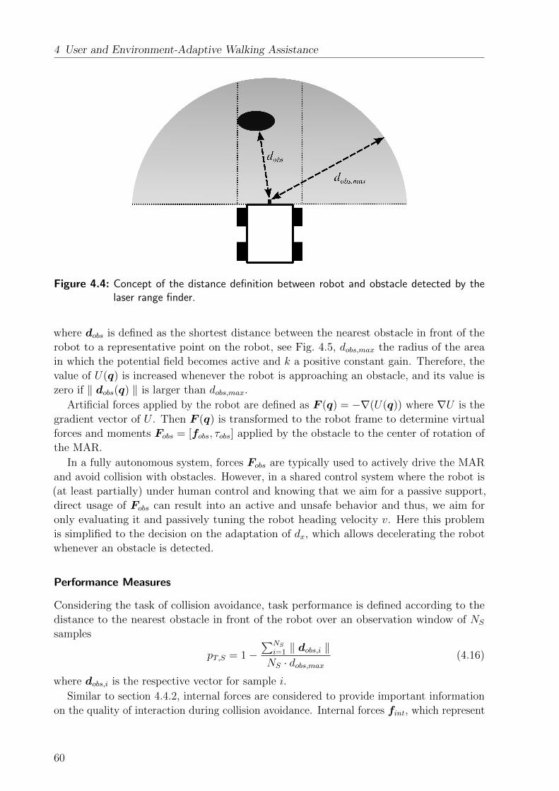
4 User and Environment-Adaptive Walking Assistance
Figure 4.4: Concept of the distance definition between robot and obstacle detected by thelaser range finder.
where dobs is defined as the shortest distance between the nearest obstacle in front of the
robot to a representative point on the robot, see Fig. 4.5, dobs,max the radius of the area
in which the potential field becomes active and k a positive constant gain. Therefore, the
value of U(q) is increased whenever the robot is approaching an obstacle, and its value is
zero if ‖ dobs(q) ‖ is larger than dobs,max.
Artificial forces applied by the robot are defined as F (q) = −∇(U(q)) where ∇U is the
gradient vector of U . Then F (q) is transformed to the robot frame to determine virtual
forces and moments Fobs = [fobs, τobs] applied by the obstacle to the center of rotation of
the MAR.
In a fully autonomous system, forces Fobs are typically used to actively drive the MAR
and avoid collision with obstacles. However, in a shared control system where the robot is
(at least partially) under human control and knowing that we aim for a passive support,
direct usage of Fobs can result into an active and unsafe behavior and thus, we aim for
only evaluating it and passively tuning the robot heading velocity v. Here this problem
is simplified to the decision on the adaptation of dx, which allows decelerating the robot
whenever an obstacle is detected.
Performance Measures
Considering the task of collision avoidance, task performance is defined according to the
distance to the nearest obstacle in front of the robot over an observation window of NS
samples
pT,S = 1−∑NS
i=1 ‖ dobs,i ‖NS · dobs,max
(4.16)
where dobs,i is the respective vector for sample i.
Similar to section 4.4.2, internal forces are considered to provide important information
on the quality of interaction during collision avoidance. Internal forces fint, which represent
60
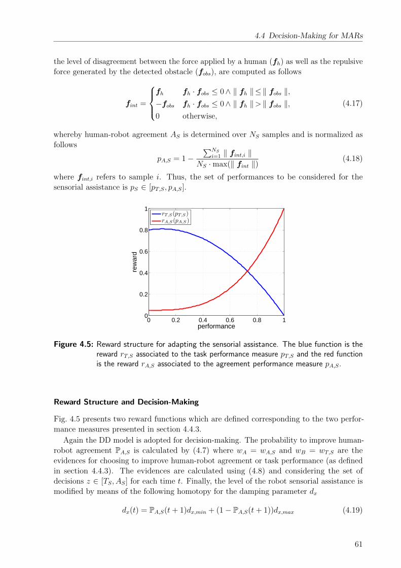
4.4 Decision-Making for MARs
the level of disagreement between the force applied by a human (fh) as well as the repulsive
force generated by the detected obstacle (fobs), are computed as follows
fint =
fh fh · fobs ≤ 0∧ ‖ fh ‖≤‖ fobs ‖,−fobs fh · fobs ≤ 0∧ ‖ fh ‖> ‖ fobs ‖,0 otherwise,
(4.17)
whereby human-robot agreement AS is determined over NS samples and is normalized as
follows
pA,S = 1−∑NS
i=1 ‖ fint,i ‖NS ·max(‖ fint ‖)
(4.18)
where fint,i refers to sample i. Thus, the set of performances to be considered for the
sensorial assistance is pS ∈ [pT,S, pA,S].
0 0.2 0.4 0.6 0.8 10
0.2
0.4
0.6
0.8
1
performance
rew
ard
rT,S (pT,S )rA,S (pA,S )
Figure 4.5: Reward structure for adapting the sensorial assistance. The blue function is thereward rT,S associated to the task performance measure pT,S and the red functionis the reward rA,S associated to the agreement performance measure pA,S.
Reward Structure and Decision-Making
Fig. 4.5 presents two reward functions which are defined corresponding to the two perfor-
mance measures presented in section 4.4.3.
Again the DD model is adopted for decision-making. The probability to improve human-
robot agreement PA,S is calculated by (4.7) where wA = wA,S and wB = wT,S are the
evidences for choosing to improve human-robot agreement or task performance (as defined
in section 4.4.3). The evidences are calculated using (4.8) and considering the set of
decisions z ∈ [TS, AS] for each time t. Finally, the level of the robot sensorial assistance is
modified by means of the following homotopy for the damping parameter dx
dx(t) = PA,S(t+ 1)dx,min + (1− PA,S(t+ 1))dx,max (4.19)
61

4 User and Environment-Adaptive Walking Assistance
where dx,min and dx,max are the minimum and maximum considered values of the damping
factor.
We believe that the proposed reward structure satisfies the objectives for providing
sensorial assistance as introduced in section 4.4.3. When no obstacle is detected in front of
the robot, the task performance measure is at its minimum (see (4.16)) and therefore a
high reward is associated to it. On the other hand, no obstacles implies no disagreement
between human and robot (based on the definition of the performance measures), which
results in a large value for the measure of human-robot agreement and therefore a high
reward. The maximum value of the reward for human-robot agreement has been decided
to be slightly larger than the maximum value of the reward for task performance, which
implies a preference to improve human-robot agreement whenever no risk of collision is
detected. In other words, the value of PA,S is close to one due to the fact that the evidence
∆wS = wA,S − wT,S is at its maximum according to the rewards defined.
As soon as an obstacle is detected, the reward for improving task performance decreases
with a slower rate with respect to the reward for human-robot agreement. This allows a
faster change from preferring human-robot agreement to task performance, the value of ∆wSdecreases, which results in an increase of the level of assistance. Finally, if the human insists
on continuing the motion forward despite the provided resistance of the robot (which can
imply the user’s interest to approach the obstacle), the task performance measure tends to
its maximum value (corresponding to the lowest reward), while the human-robot agreement
measure tends to its lowest value (also corresponding to a low reward). In this case the
overall preference turns back again towards improving human-robot agreement since its
minimum reward is larger than the minimum reward for task performance. This results in
an increase of ∆wS allowing the user to approach the obstacle. However, approaching the
obstacle has very low risk of collision since the robot velocity has been reduced significantly
and the human remains under partial robot assistance.
4.4.4 Decision on Physical Assistance
Individualization of the robot support is considered by adapting the physical robot assistance
by gain-scheduling the parameter k2 as detailed in the following sections.
Problem Formulation
The demand for assistance of elderly and patients may increase with continuing activity
due to fatigue. An assistance strategy that adapts to the current physiological state can
meet the aforementioned demand and thus, can result in a higher user’s satisfaction during
interaction with the robot. This requires that the MAR not only evaluates the user’s
performance with respect to the desired task, but also estimates the physiological state of
the user in order to decide on the level of the provided robot assistance. Specifically, we aim
at shifting the control authority to the robot if task performance is low and human fatigue
high and at gradually returning authority to the user when task performance improves and
human fatigue decreases. Again, this is formulated as decision-making problem.
We propose an active support by applying an assistive torque to the admittance model.
Considering (4.4) and (4.5), the input torque can be manipulated by a proper selection of
62

4.4 Decision-Making for MARs
the parameter k2.
Performance Measures
In general two different types of human fatigue are studied in literature: mental and
physical. Physical fatigue, which we focus on in this thesis, presents the maximum level
of exhaustion at which the human cannot exert any more work.2 In literature, medical
indicators of human fatigue are mostly discussed based on heart rate or the total performed
work. Since the former requires an external monitoring system, e.g. heart rate sensor, we
mainly focus on the latter. Physical fatigue is directly related to the total power consumed
in the human muscles and therefore total work performed as presented by [180]. The total
work performed by a person during walking is related to the user’s walking velocity and
the total weight of the user. Authors in [181] proposed the following formula that relates
consumed calories per kilogram per hour lcal to the user’s velocity vh during walking
lcal(vh) = 14.326vh
0.362 + 0.257vh(0.136vh + 0.066v2h). (4.20)
We use the aforementioned formula to formulate the level of the human fatigue during
walking. Considering a person with total weight of M pushing a MAR with apparent mass
mx and moving with linear velocity of vh = v(t) at time t, the normalized level of human
fatigue is estimated as
F (t+ 1) = F (t) +lcal(v(t))(M +mx)∆t
lcal,fat, (4.21)
where F represents the level of human fatigue, ∆t the sampling time of the system and
lcal,fat the maximum possible consumed calories resulting in human fatigue. 3 We define
pF,O = 1− F (4.22)
to be the performance measure correlating with the estimated human fatigue.
The overall task performance is defined based on the tracking error of the desired path
as well as the distance to the nearest obstacle in front of the robot which is computed as
follows
pT,O =
∑NO
i=1 |δi|NOδmax
, (4.23)
δ = kO,θe · θe + kO,e · e+ kO,obs ·1
‖ dobs ‖, (4.24)
where δi is defined as a measure of total task performance at sample i, δmax the maximum
2Please note that the natural definition of mental and physical fatigue are closely related and it iscommonly known that physical fatigue impairs mental fatigue. However, [179] has only recently shownthat mental fatigue can also imply physical fatigue. Therefore, we just consider the effect of physicalfatigue since this is the most probable cause of fatigue in a mobility assistance scenario.
3The work performed by a human to maneuver the platform has not been considered in the computationof human fatigue for the sake of simplicity.
63
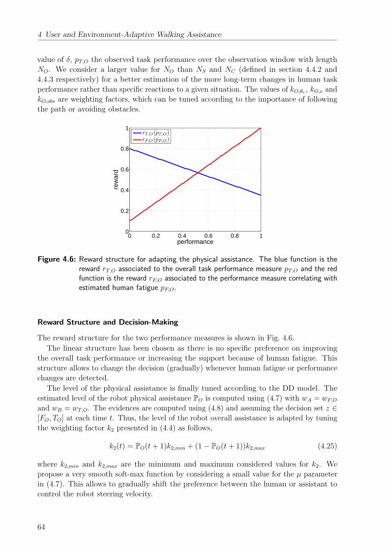
4 User and Environment-Adaptive Walking Assistance
value of δ, pT,O the observed task performance over the observation window with length
NO. We consider a larger value for NO than NS and NC (defined in section 4.4.2 and
4.4.3 respectively) for a better estimation of the more long-term changes in human task
performance rather than specific reactions to a given situation. The values of kO,θe , kO,e and
kO,obs are weighting factors, which can be tuned according to the importance of following
the path or avoiding obstacles.
0 0.2 0.4 0.6 0.8 10
0.2
0.4
0.6
0.8
1
performance
rew
ard
rT,O(pT,O)rF,O(pF,O)
Figure 4.6: Reward structure for adapting the physical assistance. The blue function is thereward rT,O associated to the overall task performance measure pT,O and the redfunction is the reward rF,O associated to the performance measure correlating withestimated human fatigue pF,O.
Reward Structure and Decision-Making
The reward structure for the two performance measures is shown in Fig. 4.6.
The linear structure has been chosen as there is no specific preference on improving
the overall task performance or increasing the support because of human fatigue. This
structure allows to change the decision (gradually) whenever human fatigue or performance
changes are detected.
The level of the physical assistance is finally tuned according to the DD model. The
estimated level of the robot physical assistance PO is computed using (4.7) with wA = wF,Oand wB = wT,O. The evidences are computed using (4.8) and assuming the decision set z ∈[FO, TO] at each time t. Thus, the level of the robot overall assistance is adapted by tuning
the weighting factor k2 presented in (4.4) as follows,
k2(t) = PO(t+ 1)k2,min + (1− PO(t+ 1))k2,max (4.25)
where k2,min and k2,max are the minimum and maximum considered values for k2. We
propose a very smooth soft-max function by considering a small value for the µ parameter
in (4.7). This allows to gradually shift the preference between the human or assistant to
control the robot steering velocity.
64

4.5 Experimental Results
Finally, to recover the orientation error a robot assistive moment can be generated using
the following control law
τassis = Kp1e+Kp2θe, (4.26)
where Kp1, Kp2 are user-specific defined gains.
4.5 Experimental Results
This section illustrates the effectiveness of the proposed approach, first by means of
experiments aiming for a technical validation with a healthy user interacting with the
platform and then by means of a user study involving 35 elderly persons.
4.5.1 Technical Validation
In the following sections we technically validate the proposed decision making algorithm
realizing adaptive shared control in MAR.
Experimental Setup
The robotic platform as shown in Fig. 3.8 was used for validation of the presented adaptive
shared control approach. The controller of the robot mobile base was implemented using
MATLAB/Simulink Real-Time Workshop. The robot velocity was controlled using a
low-level high gain PD controller. The control loop was set to run at T = 1ms sampling
time. The robot handles were not actuated and kept at a constant height during the whole
experiments.
A static map of the experimental room was build in the Robot Operating System (ROS)
using the OPENSLAM Gmapping library package based on captured laser scanner, IMU
and robot’s odometry data. A path planner as part of the move base package in ROS was
implemented that provides a fast interpolated path planning function used to create plans
for the mobile base.
For determining the closest point, we used a planner that assumes a circular robot and
operates on a cost map, which produces a global path from a starting robot pose to an end
pose in a grid. Then, an algorithm was used that searches iteratively on the global path
to find the closest points to the current robot position. To solve ambiguity in case two or
more closest points are found, we implemented a look-ahead checker, which processes past
closest points and returns the next closest point which is located ahead of the robot and
has the maximum orientation alignment with the current robot pose.
Robot localization was performed using an Adaptive Monte Carlo Localization (amcl)
approach, which was implemented in ROS as part of the nav stack package and provides
an estimate of the robot’s pose against a known map. It continuously registers the robot
pose on the map and corrects possible odometry errors.
An obstacle map based on the front laser scanner was constructed in order to provide
information about the closest obstacle in defined zones around the robot. We splitted the
area in front of the robot into 5 zones and computed the distance of the nearest obstacle in
each zone to the robot, see Fig. 4.7 for a snapshot.
65

4 User and Environment-Adaptive Walking Assistance
Test Scenarios
The presented approach was tested using two scenarios. In the first scenario the integration
of the cognitive, sensorial and physical assistance was tested, while in the second scenario
we specifically investigated the performance of the realized sensorial assistance and its
ability to avoid obstacles or allow their intentional approach.
Scenario I: The user was asked to define a desired destination on the map of the exper-
imental area shown on the screen mounted on the robot frame. According to the user’s
choice, a reference path was automatically generated to the final destination. The user was
asked to follow the path while trying to deviate from the path at least once. At half way,
another human was asked to pass in front of the robot simulating a dynamic obstacle. The
user was instructed to not pay attention to this dynamic obstacle, pretending of not having
noticed it. Towards the end of the path the user was asked to keep the robot orientation
slightly off the reference path to test the effect of the robot physical assistance.
Figure 4.7: Snapshots taken during the human-robot cooperation in scenario I. The map ofthe area is depicted in gray, while the dark gray areas show the occupied staticobstacles found during the map building. The yellow points indicate the locationof observed obstacles during the experiment. The blue point clouds are clustersaround each obstacle in the vicinity of the robot (this is only for presentationpurposes and has no application in the presented approach). The area in frontof the robot is divided into 5 zones as shown in thick red lines. The generatedreference path is presented by thin red, while the path the robot passed is shownwith yellow line (can be seen near the reference path behind the robot). Eachsnapshot presents the following information from left to right, 1: initial phase ofwalking where no obstacles are detected and the user is well following the path, 2:a dynamic obstacle moves in front of the robot, 3: the user is deviating from thereference path 4: increase of the user’s deviation is restricted by the robot andtherefore the user comes back to the path, 5: the user keeps an orientation errorat the end of the experiment, and 6: the robot physical assistance recovers theorientation error.
The parameters used for realizing the cognitive assistance were as follows: NC = 2500,
kC,e = 5 and kC,θe = 10. We considered µC = 0.6 in order to increase certainty in the
decision making and to avoid chattering. For the sensorial assistance functionality, we set
dobs,max = 0.85m, NS = 2500 and µS = 10. For the physical assistance we exaggerated the
value of lcal,fat = 104 for the sake of presentation to be able to detect human fatigue after
a short duration of walking, although the real value of lcal,fat is much higher and can be
66

4.5 Experimental Results
Table 4.1: Defined reward structures for robot assistance.
reward structure
cognitive asistancerT,C(pT,C) = pT,C
3 − 0.1
rA,C(pA,C) = −pA,C3 + 0.8
sensorial asistancerT,S(pT,S) = 0.95pT,S
3 + 0.05
rA,S(pA,S) = −(pA,S − 0.1)2 + 0.81
physical asistancerT,O(pT,O) = 0.9pT,O + 0.1
rF,O(pF,O) = −0.45pF,O + 0.8
determined from literature. We mostly focused on the error of the robot orientation with
respect to the reference path in order to actively point the human towards the destination.
Therefore, we set kO,θe = 8, kO,e = 5 and kO,obs = 1. The value of forgetting factor λ = 0.6
was considered for all cases, while the value of NO = 104 and µO = 12 were selected
in the admittance model. To fulfill the requirements of the desired robot assistance in
all three cases, the reward structures were defined as presented in Table 4.1. Moreover,
the parameters for the desired inertia of the admittance controller were considered to be
mx = 15 and Iθ = 5.
Figure 4.7 shows some snapshots taken during the experiment. The map of the exper-
imental area, the robot and defined obstacle zones, detected obstacles at the front and
around the robot as well as the desired and traveled path are shown.
At the beginning of the experiment a dynamic obstacle (another person) was passing in
front of the robot (≈ 30 < t < 32s). As depicted in Fig. 4.8, when the robot approaches the
obstacle the task performance increases. Moreover, since the user was asked to not react to
the obstacle, the agreement between the robot being interested in avoiding the obstacle
and the human not reacting properly decreases. Taking into account the defined reward
structure, the human receives a quite low reward which results in triggering the robot
decision to increase the robot assistance which was achieved by automatically increasing
the damping factor and therefore reducing the robot approaching velocity to the obstacle.
As soon as the dynamic obstacle passed the robot and the risk of collision reduced again,
the robot decided to return the authority of controlling the motion of the robot to the user,
which happened quite smooth, but fast (with respect to the first decision of increasing the
assistance) in order to avoid the user pushing against a blocked robot while there is no
obstacle in front of it.
When trying to deviate from the path (≈ 35 < t < 37 s) as shown in Fig. 4.9 the task
performance increases, while the agreement decreases as the robot preferred to stay on the
path, while the human was deviating from it. Therefore the robot assistance hindering the
user from further deviating from the path is activated and the value of the damping dθ is
increased. This notifies the user that the current direction of motion is not aligned with
the desired reference path. However, as soon as the user adapts his input and aligns the
robot with the desired path, the robot assistance quickly returns the authority to control
67
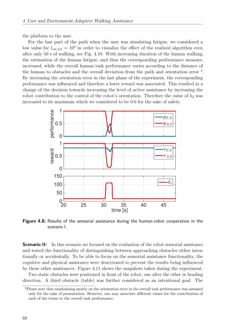
4 User and Environment-Adaptive Walking Assistance
the platform to the user.
For the last part of the path when the user was simulating fatigue, we considered a
low value for lcal,fat = 104 in order to visualize the effect of the realized algorithm even
after only 50 s of walking, see Fig. 4.10. With increasing duration of the human walking,
the estimation of the human fatigue, and thus the corresponding performance measure,
increased, while the overall human task performance varies according to the distance of
the human to obstacles and the overall deviation from the path and orientation error 4.
By increasing the orientation error in the last phase of the experiment, the corresponding
performance was influenced and therefore a lower reward was associated. This resulted in a
change of the decision towards increasing the level of active assistance by increasing the
robot contribution to the control of the robot’s orientation. Therefore the value of k2 was
increased to its maximum which we considered to be 0.6 for the sake of safety.
perf
orm
ance
0
0.5
1pT,SpA,S
rew
ard
0
0.5
1rT,SrA,S
time [s]20 25 30 35 40 45
0
50
100
150dx
Figure 4.8: Results of the sensorial assistance during the human-robot cooperation in thescenario I.
Scenario II: In this scenario we focused on the evaluation of the robot sensorial assistance
and tested the functionality of distinguishing between approaching obstacles either inten-
tionally or accidentally. To be able to focus on the sensorial assistance functionality, the
cognitive and physical assistance were deactivated to prevent the results being influenced
by these other assistances. Figure 4.11 shows the snapshots taken during the experiment.
Two static obstacles were positioned in front of the robot, one after the other in heading
direction. A third obstacle (table) was further considered as an intentional goal. The
4Please note that emphasizing mostly on the orientation error in the overall task performance was assumedonly for the sake of presentation. However, one may associate different values for the contribution ofeach of the terms to the overall task performance.
68
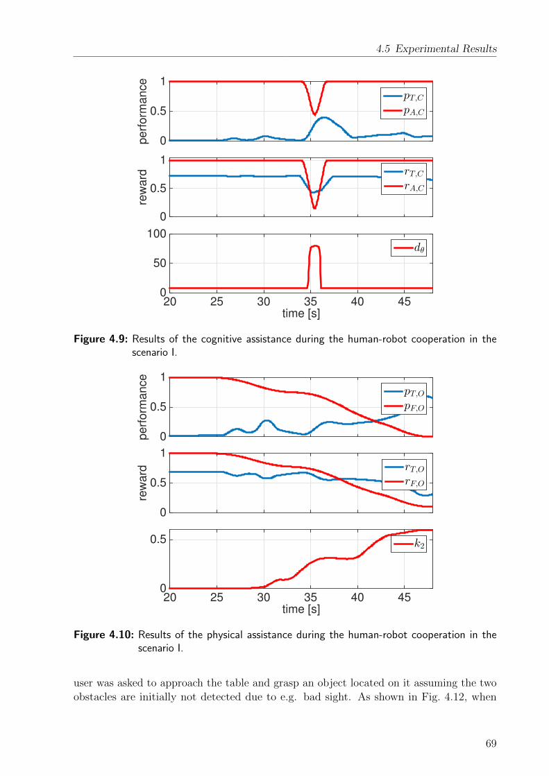
4.5 Experimental Results
perf
orm
ance
0
0.5
1pT,CpA,C
rew
ard
0
0.5
1rT,CrA,C
time [s]20 25 30 35 40 45
0
50
100dθ
Figure 4.9: Results of the cognitive assistance during the human-robot cooperation in thescenario I.
perf
orm
ance
0
0.5
1pT,OpF,O
rew
ard
0
0.5
1rT,OrF,O
time [s]20 25 30 35 40 45
0
0.5 k2
Figure 4.10: Results of the physical assistance during the human-robot cooperation in thescenario I.
user was asked to approach the table and grasp an object located on it assuming the two
obstacles are initially not detected due to e.g. bad sight. As shown in Fig. 4.12, when
69
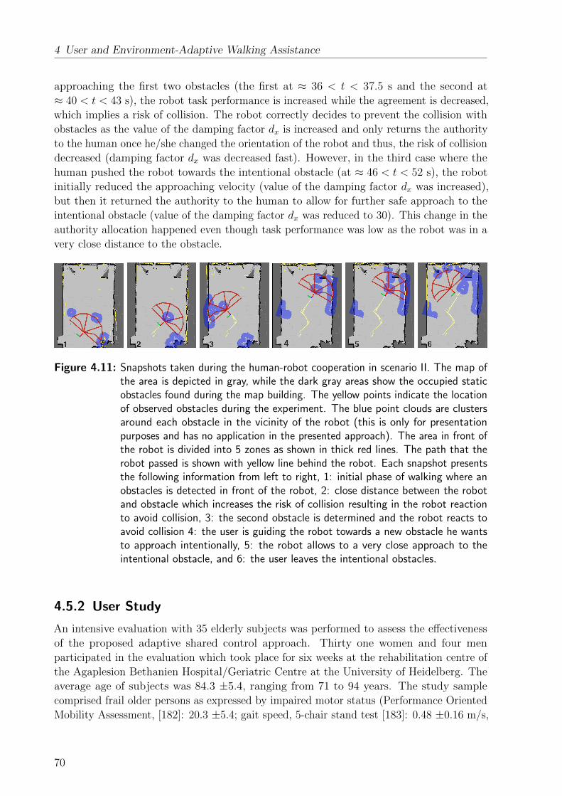
4 User and Environment-Adaptive Walking Assistance
approaching the first two obstacles (the first at ≈ 36 < t < 37.5 s and the second at
≈ 40 < t < 43 s), the robot task performance is increased while the agreement is decreased,
which implies a risk of collision. The robot correctly decides to prevent the collision with
obstacles as the value of the damping factor dx is increased and only returns the authority
to the human once he/she changed the orientation of the robot and thus, the risk of collision
decreased (damping factor dx was decreased fast). However, in the third case where the
human pushed the robot towards the intentional obstacle (at ≈ 46 < t < 52 s), the robot
initially reduced the approaching velocity (value of the damping factor dx was increased),
but then it returned the authority to the human to allow for further safe approach to the
intentional obstacle (value of the damping factor dx was reduced to 30). This change in the
authority allocation happened even though task performance was low as the robot was in a
very close distance to the obstacle.
Figure 4.11: Snapshots taken during the human-robot cooperation in scenario II. The map ofthe area is depicted in gray, while the dark gray areas show the occupied staticobstacles found during the map building. The yellow points indicate the locationof observed obstacles during the experiment. The blue point clouds are clustersaround each obstacle in the vicinity of the robot (this is only for presentationpurposes and has no application in the presented approach). The area in front ofthe robot is divided into 5 zones as shown in thick red lines. The path that therobot passed is shown with yellow line behind the robot. Each snapshot presentsthe following information from left to right, 1: initial phase of walking where anobstacles is detected in front of the robot, 2: close distance between the robotand obstacle which increases the risk of collision resulting in the robot reactionto avoid collision, 3: the second obstacle is determined and the robot reacts toavoid collision 4: the user is guiding the robot towards a new obstacle he wantsto approach intentionally, 5: the robot allows to a very close approach to theintentional obstacle, and 6: the user leaves the intentional obstacles.
4.5.2 User Study
An intensive evaluation with 35 elderly subjects was performed to assess the effectiveness
of the proposed adaptive shared control approach. Thirty one women and four men
participated in the evaluation which took place for six weeks at the rehabilitation centre of
the Agaplesion Bethanien Hospital/Geriatric Centre at the University of Heidelberg. The
average age of subjects was 84.3 ±5.4, ranging from 71 to 94 years. The study sample
comprised frail older persons as expressed by impaired motor status (Performance Oriented
Mobility Assessment, [182]: 20.3 ±5.4; gait speed, 5-chair stand test [183]: 0.48 ±0.16 m/s,
70

4.5 Experimental Results
pe
rfo
rma
nce
0
0.5
1pT,SpA,S
rew
ard
0
0.5
1rT,SrA,S
time [s]30 35 40 45 50 55 60
0
50
100
150dx
Figure 4.12: Results of the sensorial assistance during the human-robot cooperation in thescenario II.
19.2 ±7.5 s) and high risk of falling (63 % of subjects reported one or more falls in the
last year). All subjects currently used conventional walkers in their daily routine. The
experiments were performed under ethical approval by the ethics committee of the Medical
Department of the University of Heidelberg, Alte Glockengießerei 11/1, 69115 Heidelberg,
Germany. Written informed consent was obtained from all subjects participating in the
study.
Test Conditions
The adaptive shared control approach for sensorial assistance has been implemented on the
robotic platform and was compared with an existing approach in literature. We considered
three different conditions:
• C1: Walking assistance without obstacle avoidance functionality implementing a
constant virtual inertia and damping.
• C2: Walking assistance with obstacle avoidance based on the approach presented by
[184].
• C3: Walking assistance with obstacle avoidance based on the decision-making algo-
rithm presented in this manuscript.
The main reason for focusing on the evaluation of the sensorial assistance in the user
study is that beside the baseline C1 there is hardly any directly comparable algorithm
available for the other two modes.
71

4 User and Environment-Adaptive Walking Assistance
For a fair comparison, base values of mx = 15 kg and Iθ = 5 kgm2, and of dx = 10 Ns/m
and dθ = 10 Nms/rad were considered for each condition. These values were selected
after discussion with rehabilitation experts. Although the above mentioned values were
considered constant for condition C1, the value of dx and dθ were adapted up to their
maximum of dx,max = 110 Ns/m and dθ,max = 80 Nms/rad in C2 and C3. The maximum
values were selected following discussions with rehabilitation experts as well as tests to
achieve a good maneuverability of the device with respect to a standard non-motorized
walker. We considered 70 cm distance between the robot and obstacles as the activation
distance, i.e. the base values were considered in C2 and C3 only for distances larger than
70 cm, while the adaptation laws were applied for distances less than 70 cm.
Experimental Setup
A special test environment was prepared within the Bethanien rehabilitation center to test
the proposed adaptive shared control approach. Figure 4.13 shows the map of the test
environment and a representative example of a test path. The test environment covered an
area of about 10× 9 m with an approximate length of 40 meters of test path starting from
an initial position, passing through the narrow corridor by avoiding obstacles and coming
back to the same initial position. The height of obstacles varied in different sections of the
area. The considered round trip allowed us to record the same number of left and right
turns. Over the whole trial the user was faced to 17 obstacles, and a minimum amount of
16 turns either to avoid collisions with obstacles or to perform turns along the path. No
reference path was marked on the ground during tests.
2 m
Figure 4.13: Map of the evaluation course. The main walking area has a size of about 10 x9m. The corridor included three sections with obstacles and one turning area inwhich participants had to drive round a pillar (area (4)) before driving back tothe very beginning of the course. The height of obstacles varied in the differentsections as follows: 90 cm (1), 50 cm (2)+(3).
72

4.5 Experimental Results
Evaluation Method
Before participants completed the test trials, each of them was asked to drive freely through
the course. For this first run, no instructions concerning obstacle avoidance and walking
speed were given by the test supervisor, and no sensorial assistance was provided by the
robot platform. This trial was intended to familiarize the participants with the device and
course.
Each participant then completed the obstacle course under three different conditions
mentioned in section 4.5.2. The order of the conditions tested with each participant was
randomized to exclude learning effects. The participants were not told which condition
was used during the three different trials. Before starting each trial, the participants were
instructed to complete the course as fast as possible. After each trial, a sufficient recovery
phase was provided to the participants in order to prevent fatigue.
Evaluation Results
Two performance metrics were considered in order to verify the effectiveness of the proposed
sensorial assistance: number of collisions (with the front of the robotic platform) and task
completion time.
Differences in the number of collisions and task completion time between the three
conditions were statistically analysed by a one-way analyses of variance (ANOVA) and
obtained results are shown in Figs. 4.14, 4.15 and 4.16. No significant differences between
conditions C1, C2 and C3 were identified in terms of task completion time. However,
significant differences were found for the number of collisions and approaching velocity to
obstacles. Post-hoc tests (Bonferroni corrected) showed a reduced number of collisions
and reduced approaching velocity for C3 (sensorial assistance based on decision making
algorithm) compared to condition C1 (p < .05), but no significant differences between other
conditions (C2 vs. C1 / C3: p = .07/.99). The lowest approaching velocity to obstacles
was found for C3.
Figure 4.14: Completion time in the user study under three conditions (C1, C2 and C3).
73
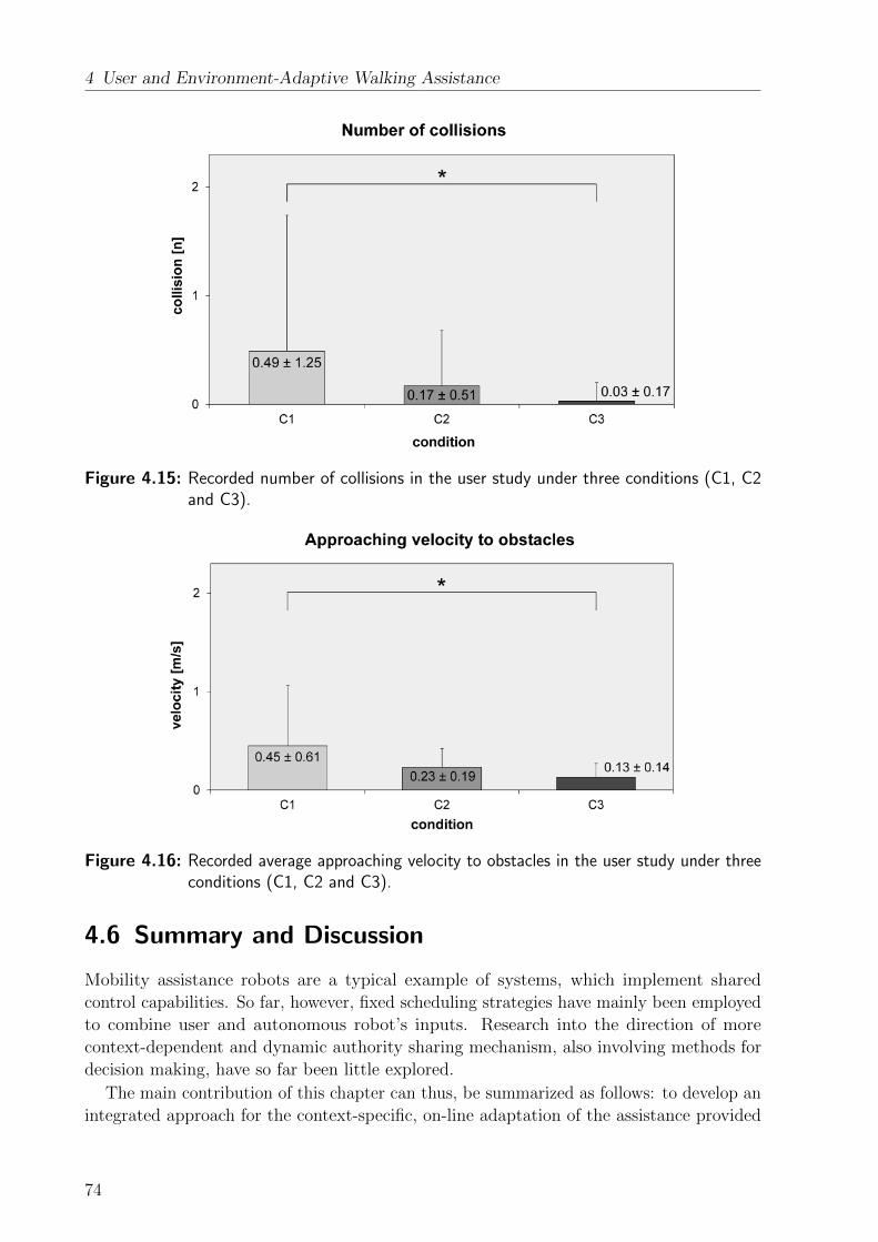
4 User and Environment-Adaptive Walking Assistance
Figure 4.15: Recorded number of collisions in the user study under three conditions (C1, C2and C3).
Figure 4.16: Recorded average approaching velocity to obstacles in the user study under threeconditions (C1, C2 and C3).
4.6 Summary and Discussion
Mobility assistance robots are a typical example of systems, which implement shared
control capabilities. So far, however, fixed scheduling strategies have mainly been employed
to combine user and autonomous robot’s inputs. Research into the direction of more
context-dependent and dynamic authority sharing mechanism, also involving methods for
decision making, have so far been little explored.
The main contribution of this chapter can thus, be summarized as follows: to develop an
integrated approach for the context-specific, on-line adaptation of the assistance provided
74

4.6 Summary and Discussion
by a rollator-type MAR, and to employ human decision-making mechanisms in the adapta-
tion laws. The shared control architecture distinguishes between short-term adaptations
providing a) cognitive assistance to support the user in following a desired path towards a
predefined destination and b) sensorial assistance to avoid collisions with obstacles and to
allow for an intentional approach of them. Furthermore, it considers a long-term adaptation
of c) the overall assistance based on long-term user’s performance and observed fatigue. To
achieve an intuitive and human-like adaptation policy of the provided assistance, a decision
making model explored in cognitive science, the Drift-Diffusion model, was employed.
The technical performance of the proposed approach was tested in two scenarios and
resulted in the desired robot behavior as the robot’s cognitive, sensorial and physical
assistance were activated as needed. The effectiveness of the proposed approach was
demonstrated in the performed user study with end-users. The lowest number of collisions,
alongside with lowest approaching velocity to obstacles was found when the user was passing
the obstacle course using our newly proposed algorithm. However, similar task completion
times for all conditions indicated that the proposed sensorial assistance approach does
not interfere with the normal activity of the patients and furthermore guarantees a safe
intentional approach to obstacles if needed.
One of the main practical challenges in the presented work was tuning basic and
maximum values of adjustable parameters. We finally agreed on the chosen values based
on discussions with experts. Furthermore, the selection of suitable performance metrics
and reward structures strongly affects the performance of the algorithm and a series of
alternative performance metrics and related reward structures could have been chosen
instead. We don’t argue that our selection is the best, but that it fulfills the desired
purpose of improving sensorial, cognitive and physical assistance. Further investigations of
performance metrics and reward structures, possibly being time and context-dependent, can
be a focus of future research. Moreover, employment of different human-decision making
models for the control design of MARs can be further investigated, since only the DDM
model was studied in this chapter.
While this chapter aimed to ensure safety in human-robot interaction by realizing as
passive as possible robot behavior, the next chapter will further propose solutions for the
prevention of possible human falls to enhance human’s safety.
75
5 Human Fall Prevention Assistance
This thesis so far presented novel approaches for the biologically-inspired control design of
MARs implementing two modes of sit-to-stand and walking assistance, while fall prevention
(the last considered mode of operations in this thesis) is discussed in this chapter. For
the first time, we propose an optimal control approach for human fall prevention when
interacting with a MAR equipped with a pair of actuated arms.
Fall prevention is especially important since falls of elderly have a high probability to
cause severe injuries that are risk factors for further disability [185].
In literature fall prevention functionalities are presented mostly for passive systems
without actuated arms [186, 187]. In [186, 188] user’s falls are estimated by evaluating
the relative distance between the user’s legs and the MAR measured using a laser range
finder and averaged to estimate the projected user’s Center of Mass (COM). This feature is
compared to its user-specific normal distribution during walking to determine the probability
of a user’s fall and to activate the brakes accordingly. The risk of falling is defined to
increase if the projection of the COM approached the border of the support polygon.
Human falls are recognized along the horizontal direction (caused for example by stumbling
and leading to legs that are far apart from the walker), and falls along the vertical direction
(caused for example by weak legs). Finally, varying admittance control is realized for fall
prevention by increasing the damping in the desired admittance if the user is found to be
in a falling state achieved by activating the brakes accordingly, while in the stopped state
large brake torques are applied to each of the wheels independently of the user’s applied
force to the system.
A basic challenge in designing a suitable control approach for assistance robots with
fall prevention functionality is to select a proper human fall detection measure. The most
sophisticated measure used in the aforementioned fall prevention algorithms is the human
COM, which, however, cannot fully capture human balance [189]. The Zero Moment
Point (ZMP) or Center of Pressure (CoP) determines the human balance more accurately
[103, 190]. Human balance is guaranteed if the ZMP or COP stay within a support polygon
that is either the area of a foot or both feet depending on the gait phase. Although
these features depend on the COM position and its acceleration, their computation is very
complex, especially for a human interacting with an assistance robot. In contrary, the
Extrapolated Center of Mass (XCOM) (or Instantaneous Capture Point) has shown several
advantages in human or humanoid balance studies [191–196]. As we will show, XCOM is
easier to compute since it is related to the COM and its velocity rather than acceleration,
and it can be faster in fall detection than the COM as the COM velocity provides a simple
prediction of the COM future behavior.
The novelty in this chapter lies thus in the development of a fall prevention approach for
a MAR equipped with a pair of actuated arms, never being exploited so far. We propose
an algorithm that evaluates the user’s XCOM and determines required supportive forces to
76

5.1 System Description
be applied to the user for fall prevention as soon as a risk of fall is predicted. Derivation of
the required assistive forces are formulated as an optimization problem, while the obtained
forces are realized by a MAR using a compliance controller. We further show applicability
of the proposed approach by experimental evaluation using a MAR that supports subjects
provoking falls in forward, backward and sideways directions.
This chapter firstly describes equations of motion of a MAR and the simplified human
model in section 5.1. Then, section 5.2 presents the fall prevention control approach, while
simulation and experimental results are reported in section 5.3. Finally, a summary and
conclusion is given in section 5.4.
5.1 System Description
In the following section we present models for the MAR and human assuming rigid grasp
conditions.
5.1.1 Robot Model
The considered MAR in section 4.2.1 is employed. We consider that both arms are
independently actuated in order to transfer supportive forces to the human. Considering
the kinematic model of the robot base presented as in (4.1), the kinematic model of
left (l) and right (r) robotic arm is defined as xarm,i = Jarm,iqi where xarm,i are the
Cartesian velocity of the tip of the arm i ∈ (l or r) with respect to its base frame and
qi =[q1,i, q2,i, . . . , qn,i
]Tthe arm joint velocities.
5.1.2 Human Model
In literature human models with different complexity have been studied. More complex
models comprising a high number of human segments typically require an accurate tracking
system. Simpler models such as a linear inverted pendulum (LIP) provide less accurate
estimation of the human segment locations, but lead to lower complexity in computation
and implementation even for real-time purposes. The LIP model has been widely used in
human balance studies and gait analysis (see [191, 192, 194, 197]) and is therefore used
in this thesis. The LIP model has shown a very similar behavior to the real human in
balance studies, especially at the initial phase of the human movement before reaching the
unbalanced state [194, 197]. This particularly justifies the use of the LIP model in the
presented fall prevention approach, which has to provide a proper reaction before human
falls are happening.
We employ a 3D-LIP model with finite-sized feet and no slippage at the contact points
considering assistive forces applied at the interaction points as shown in Fig. 5.1. The
3D-LIP model with point foot was initially proposed by [198] for the modeling and motion
generation of bipedal walking robots and was further extended to the finite-sized model in
[197]. We slightly extended this model to allow for the inclusion of external interactions.
Finally, the mass m of the pendulum moves under the action of the forces Fassis and torques
Tassis applied by the assistance robot, the torques τ applied at the pivot joint and the
77

5 Human Fall Prevention Assistance
gravity g. The point mass is kept on a horizontal plane by generalized forces f in the
system.
Considering the position of the COM by the vector PCOM =(xCOM, yCOM , zCOM
)T,
the dynamic equation of motion is written as follows with respect to Fig. 5.1:
mPCOM = f +mg + Fassis, (5.1)
−(PCOM − P )× f + τ − Tassis = 0, (5.2)
where f =(fx, fy, fz
)Tare the internal forces acting on the point mass, Fassis =(
Fx, Fy, Fz)T
and Tassis =(Tx, Ty, Tz
)Tthe resultant external forces and torques ap-
plied to the COM due to the external forces on the interaction point and g =(0, 0, −g
)Tthe gravitational acceleration. The equation 5.2 is obtained by considering moment balance
for the massless link, where P is the position of the pivot point (e.g. the human’s ankle),
which may change when a step is taken, but is assumed to be instantaneous and therefore
has no effect on the position and velocity of the point mass. Considering that the user
firmly grasps the robot handles, Fassis and Tassis are computed as follows,
Tassis = hl × Fl + hr × Fr, (5.3)
Fassis = Fl + Fr,
where hi = (hi,x, hi,y, hi,z)T i ∈ (l, r) are the distances between the contact points and the
position of the point mass.
xr x
y
yr
ry x
Fl
Fr
Figure 5.1: Frame representation of the human and mobility assistance robot (left) and theemployed 3D Linear inverted model (3D-LIP) model.
In eq. (5.1) we obtain fz = mg − Fz, which is substituted in (5.2) to compute other
78

5.2 Fall Prevention Control
components of the generalized force f as follows,
fx = mxCOMω20
(1− Fz
mg
)− τyz0
+Tyz0, (5.4)
fy = myCOMω20
(1− Fz
mg
)+τxz0− Txz0,
where ω0 =√
gz0
is the eigenfrequency of the pendulum. Finally, the equation of motion is
given by
xCOM = xCOMω20
(1− Fz
mg
)− τymz0
+Tymz0
+Fxm, (5.5)
yCOM = yCOMω20
(1− Fz
mg
)+
τxmz0
− Txmz0
+Fym.
5.2 Fall Prevention Control
The fall prevention control approach for the considered MAR requires the i) derivation of
proper assistive forces to be applied to the user, and ii) actuation of the robotic platform
for a safe realization of these assistive forces.
5.2.1 Derivation of Assistive Forces
In this section we introduce an approach that evaluates human balance based on the XCOM
to derive assistive forces to be applied to the user for fall prevention.
Pratt et al. [196] and Hof [191] introduced the concept of the XCOM or Capture Point.
This is the point on the floor, the human or humanoid (modeled as a 3D-LIP) has to step
on such that their COM is located over the ankle with zero horizontal velocity. Given the
dynamics of the 3D-LIP in (5.5), the XCOM can be expressed as [196, 197]
PXCOM = PCOM +PCOM
ω0
, (5.6)
where (PCOM, PCOM)T is the state of the LIP. The human gait remains stable as long as
the XCOM stays within the Base of Support (BOS). The BOS typically includes the size of
the feet and the room between them [191] for a human without external support. In this
chapter we consider the human gripping the robot handles, which could result in a larger
BOS area. However, we still consider the smaller BOS for the case of no external support
in order to have a stronger balance region for the derivation of assistive forces
BOS :={PXCOM : δ− ≤ PXCOM ≤ δ+
}, (5.7)
where δ− =[δ−x , δ
−y
]and δ+ =
[δ+x , δ
+y
]define the boundaries of the BOS.
The above mentioned balance criterion can be combined with the constraint that the
COM must be able to come to a stop over the BOS and keeping the XCOM inside the base
79
5 Human Fall Prevention Assistance
of support using the following analytical relationship as discussed in [196],
δ− ≤ PXCOM +PXCOM
ω0
≤ δ+. (5.8)
This constraint represents a stability region in the COM state space that includes the effect
of the assistive forces on the LIP balance. More importantly, satisfaction of the above
criterion assures that the LIP is balanced at least during the next t = 1ω0
seconds which
can be used for estimating human falls and thus, to realize fall prevention strategies.
With the help of some matrix manipulations and after substituting (5.5) and (5.3) into
(5.7), the following inequality constraints are obtained for balance satisfaction as a function
of the applied assistive forces,
KF =[Kl Kr
] [FlFr
]≤ c, (5.9)
Ki =
−z0 − hi,z 0 xCOM + hi,xz0 + hi,z 0 −xCOM − hi,x
0 −z0 − hi,z yCOM + hi,y0 z0 + hi,z −yCOM − hi,y
,
c = mg
2xXCOM − δ−x −
τymg
δ+x + τymg− 2xXCOM
2yXCOM − δ−y + τxmg
δ+y − τxmg− 2yXCOM
,
where xXCOM and yXCOM are two components of the PXCOM, while δ+x , δ−x , δ
+y and δ−y are
the components of BOS boundaries defined in (5.8).
The torques applied to the pivot joint (τx and τy) provide support for the human balance
when the balance criterion is satisfied [191]. However, if the user looses his or her balance,
no value for τ can be applied anymore. The supportive torque is lower for weak users
and therefore we decided to neglect its effect in the derivation of supportive strategies to
consider the worst case.
A valid set of desired contact forces F is found by solving the following quadratic
programming problem,
F =arg minFF TWF (5.10)
s.t. KF ≤ c (5.11)
where W is used to weigh certain forces, or to penalize large supportive forces while
KF ≤ c represent the balance inequality constraints.
An analytic solution of this optimization problem is considered for online implementation.
If the problem is unconstrained, i.e. the inequality (5.11) holds, the trivial solution F = 0 is
obtained. However, for the constraint case the active constraints are taken into account by
using an active-set method [199], where the active set is composed of those constraints that
are satisfied as equalities and constitute the corresponding augmented matrices Ka and
80

5.2 Fall Prevention Control
ca. The associated optimization is then solved using the weighted Moore-Penrose Inverse,
F = K+a ca, that is a constrained active solution.
The inequality constraints (5.9) automatically divide the BOS into two phases: a phase
with no required control forces necessary to guarantee balance and a second phase where a
monotonically increasing force with maximum at the BOS boundary can be determined.
This intrinsic property assures no robot intervention for normal human walking or activity
since no assistive forces are determined.
5.2.2 Robot Control
To allow the human to drive the MAR during normal walking, the robot is equipped with
two force/torque sensors mounted at the handles. Force components along and around
the heading direction are used for motion control1. Position-based admittance control is
implemented, which allows to design the desired dynamic behavior of the system with
respect to the user’s applied force by selecting proper admittance parameters. A mass-
damper system for the linear and angular motion is considered as proposed in eq. (4.2) to
determine the desired reference velocities based on the human’s applied force, and then
being realized by a low-level controller.
We consider an extra mass-damper system for the derivation of the desired velocity of
the robot handles based on the obtained assistive forces Fi described in section 5.2.1 as
follows,
Md,arm,i¨xarm,i +Dd,arm,i
˙xarm,i +Kd,arm,ixarm,i = Fi, (5.12)
where Md,arm,i and Dd,arm,i are the desired inertia and damping matrices for either left
or right arms, respectively. The desired joint velocities qi are then computed using the
Pseudoinverse of the arm Jacobian,
qi = J#arm,i
˙xarm,i. (5.13)
For the sake of safety the robot base motion was slowed down whenever a risk of human
fall was determined and a stabilization maneuver needed to be performed. For this purpose,
the damping factor Dd,base was increased as a function of the norm of Fi considering the
distance of the human XCOM to the boundary of the BOS as follows
Dd,base =
{Dd,base
δ−
2≤ PXCOM ≤ δ+
2
Dd,base exp(‖ Fi ‖) else. (5.14)
In the following subsections we report on simulation and experimental results of the
proposed fall prevention control algorithm. The simulation results report on the used feature
for fall detection and the obtained assistive forces to prevent falls, while the experimental
results evaluate the effectiveness of the proposed fall prevention algorithm on a real MAR.
1Please note that in a holonomic system also the force component in sidewards direction is used for motioncontrol.
81
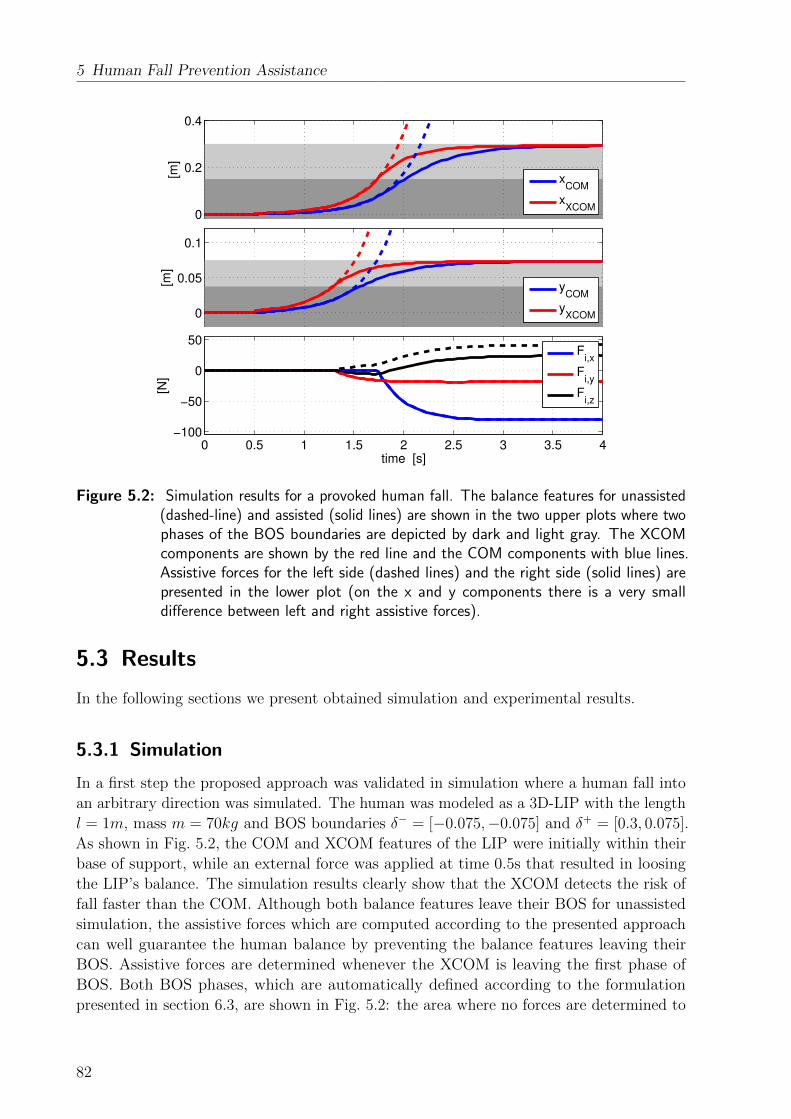
5 Human Fall Prevention Assistance
0
0.05
0.1
[m]
yCOM
yXCOM
0 0.5 1 1.5 2 2.5 3 3.5 4−100
−50
0
50
time [s]
[N]
Fi,x
Fi,y
Fi,z
0
0.2
0.4
[m]
xCOM
xXCOM
Figure 5.2: Simulation results for a provoked human fall. The balance features for unassisted(dashed-line) and assisted (solid lines) are shown in the two upper plots where twophases of the BOS boundaries are depicted by dark and light gray. The XCOMcomponents are shown by the red line and the COM components with blue lines.Assistive forces for the left side (dashed lines) and the right side (solid lines) arepresented in the lower plot (on the x and y components there is a very smalldifference between left and right assistive forces).
5.3 Results
In the following sections we present obtained simulation and experimental results.
5.3.1 Simulation
In a first step the proposed approach was validated in simulation where a human fall into
an arbitrary direction was simulated. The human was modeled as a 3D-LIP with the length
l = 1m, mass m = 70kg and BOS boundaries δ− = [−0.075,−0.075] and δ+ = [0.3, 0.075].
As shown in Fig. 5.2, the COM and XCOM features of the LIP were initially within their
base of support, while an external force was applied at time 0.5s that resulted in loosing
the LIP’s balance. The simulation results clearly show that the XCOM detects the risk of
fall faster than the COM. Although both balance features leave their BOS for unassisted
simulation, the assistive forces which are computed according to the presented approach
can well guarantee the human balance by preventing the balance features leaving their
BOS. Assistive forces are determined whenever the XCOM is leaving the first phase of
BOS. Both BOS phases, which are automatically defined according to the formulation
presented in section 6.3, are shown in Fig. 5.2: the area where no forces are determined to
82

5.3 Results
Figure 5.3: Snapshots taken during the provoked human fall experiments in sideways direction(snapshots 1 and 2) and backward direction (snapshots 4 and 5).
be applied (dark gray) and the area where forces are applied (light gray). The algorithm
starts to apply forces to the LIP to slow down the fall from two interaction points located
at hl = −hr = [0, 0.25, 0] with respect to the PCOM . As a result the human XCOM and
COM stay within the BOS (gray area) and stabilize at the boundary of the BOS, where
the COM and XCOM converge to each other. Since the fall is happening in an arbitrary
direction, violation of the XCOM in both x and y directions happens independently at
different time instances.
xX
CO
M [m
]
-0.1
0
0.1
0.2y
XC
OM
[m
]
-0.1
0
0.1
0.2
Fl
[N]
0
100
200F
x
Fz
Fr
[N]
-80
-60
-40
-20
0
Fx
Fz
time [s]
2 4 6 8 10
vb
ase [m
/s]
-0.5
0
0.5
time [s]
2 4 6 8 10
va
rms [m
/s]
-0.05
0
0.05l,x
r,x
l,y
r,y
Figure 5.4: Experimental results for a provoked sideways human fall. The balance featuresand their corresponding two phases of the BOS boundaries are depicted by darkand light gray areas in the first row. Assistive forces for the left and right armsand the realized robot base and arm velocities are depicted in the second and thirdrows, respectively.
83
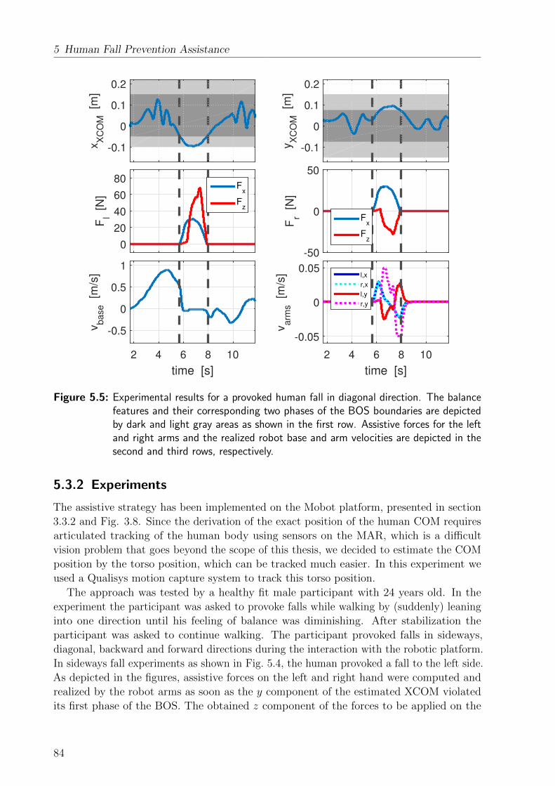
5 Human Fall Prevention Assistance
xX
CO
M [m
]
-0.1
0
0.1
0.2
yX
CO
M [m
]
-0.1
0
0.1
0.2
Fl
[N]
0
20
40
60
80F
x
Fz
Fr
[N]
-50
0
50
Fx
Fz
time [s]
2 4 6 8 10
vb
ase [m
/s]
-0.5
0
0.5
1
time [s]
2 4 6 8 10
va
rms [m
/s]
-0.05
0
0.05l,x
r,x
l,y
r,y
Figure 5.5: Experimental results for a provoked human fall in diagonal direction. The balancefeatures and their corresponding two phases of the BOS boundaries are depictedby dark and light gray areas as shown in the first row. Assistive forces for the leftand right arms and the realized robot base and arm velocities are depicted in thesecond and third rows, respectively.
5.3.2 Experiments
The assistive strategy has been implemented on the Mobot platform, presented in section
3.3.2 and Fig. 3.8. Since the derivation of the exact position of the human COM requires
articulated tracking of the human body using sensors on the MAR, which is a difficult
vision problem that goes beyond the scope of this thesis, we decided to estimate the COM
position by the torso position, which can be tracked much easier. In this experiment we
used a Qualisys motion capture system to track this torso position.
The approach was tested by a healthy fit male participant with 24 years old. In the
experiment the participant was asked to provoke falls while walking by (suddenly) leaning
into one direction until his feeling of balance was diminishing. After stabilization the
participant was asked to continue walking. The participant provoked falls in sideways,
diagonal, backward and forward directions during the interaction with the robotic platform.
In sideways fall experiments as shown in Fig. 5.4, the human provoked a fall to the left side.
As depicted in the figures, assistive forces on the left and right hand were computed and
realized by the robot arms as soon as the y component of the estimated XCOM violated
its first phase of the BOS. The obtained z component of the forces to be applied on the
84
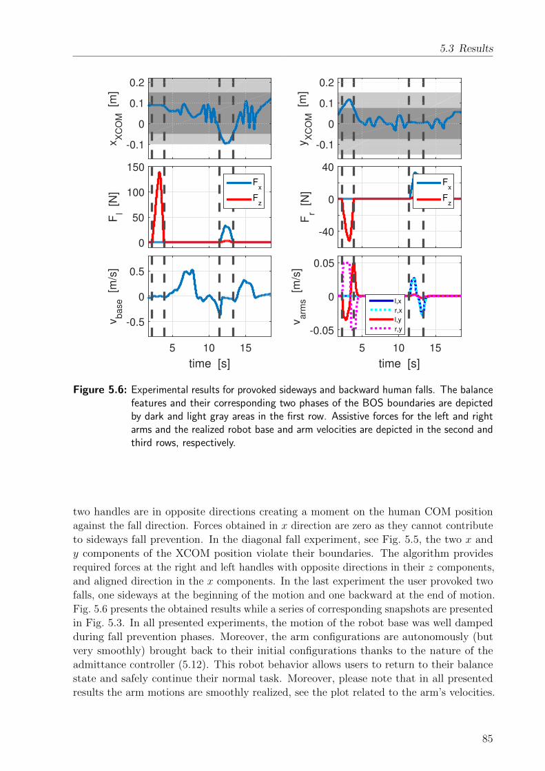
5.3 Results
xX
CO
M [m
]
-0.1
0
0.1
0.2
yX
CO
M [m
]
-0.1
0
0.1
0.2
Fl
[N]
0
50
100
150
Fx
Fz
Fr
[N]
-40
0
40
Fx
Fz
time [s]
5 10 15
vb
ase [m
/s]
-0.5
0
0.5
time [s]
5 10 15
va
rms [m
/s]
-0.05
0
0.05
l,x
r,x
l,y
r,y
Figure 5.6: Experimental results for provoked sideways and backward human falls. The balancefeatures and their corresponding two phases of the BOS boundaries are depictedby dark and light gray areas in the first row. Assistive forces for the left and rightarms and the realized robot base and arm velocities are depicted in the second andthird rows, respectively.
two handles are in opposite directions creating a moment on the human COM position
against the fall direction. Forces obtained in x direction are zero as they cannot contribute
to sideways fall prevention. In the diagonal fall experiment, see Fig. 5.5, the two x and
y components of the XCOM position violate their boundaries. The algorithm provides
required forces at the right and left handles with opposite directions in their z components,
and aligned direction in the x components. In the last experiment the user provoked two
falls, one sideways at the beginning of the motion and one backward at the end of motion.
Fig. 5.6 presents the obtained results while a series of corresponding snapshots are presented
in Fig. 5.3. In all presented experiments, the motion of the robot base was well damped
during fall prevention phases. Moreover, the arm configurations are autonomously (but
very smoothly) brought back to their initial configurations thanks to the nature of the
admittance controller (5.12). This robot behavior allows users to return to their balance
state and safely continue their normal task. Moreover, please note that in all presented
results the arm motions are smoothly realized, see the plot related to the arm’s velocities.
85

5 Human Fall Prevention Assistance
5.4 Summary and Discussion
Human falls while interacting with a MAR is a critical event and needs to be prevented.
Available approaches for human fall prevention have been mainly developed for passive
platforms without actuated arms. Moreover, only braking strategies were realized for fall
prevention. The approach presented in this chapter, for the first time, proposes optimal
solutions for human fall prevention. Although the COM was typically used as the human’s
fall detection measure in MARs, this chapter proposes to evaluate the user’s Extrapolated
Center of Mass (XCOM) (which is faster in fall detection than the COM) in order to
determine the required supportive forces to be provided to the user for fall prevention. The
human was modeled as a 3D-LIP while the assistive forces were applied at two interaction
points between human and robot arms. Finally, a compliant robot controller was proposed
to realize the required forces for fall prevention. Applicability and performance of the
proposed approach were evaluated in experiments on the robotic platform supporting a
subject provoking falls in different directions.
The main restriction of the presented approach is the required online estimation of the
user’s COM and its derivative. These can be performed by online evaluation of vision data,
such as camera or Kinect sensors. Therefore, future research may be directed towards
the development of reliable algorithms for articulated tracking of the users interacting
with MARs, and the estimation of required information such as the COM position. Such
algorithms can also help developing more sophisticated assistive strategies for human fall
prevention by providing further information on human states and positions of the body
segments, e.g. hand or leg configurations.
This thesis so far focused on different human safety aspects in the control design for each
mode of operation. Human safety was considered in chapter 3, by considering the balance
criteria aiming at avoiding human falls during STS transfers, in chapter 4 by developing
an as passive as possible assistive strategy, and in this chapter by proposing an optimal
human fall prevention approach. The safety aspect is emphasized even further in the next
chapter by realizing a general safety supervisory controller that aims at supervising the
behavior of the specific control unit in the specified mode of operation and reshaping the
robot’s behavior to enhance the user’s safety if an unsafe situation is about to happen.
86

6 Energy-Based Supervisory Control for SafetyEnhancement
Enhancing safety of the human is a critical issue to be addressed for every collaborative
robot system, especially assistance robots that interact with the elderly or patients. So far,
this thesis has focused on different aspects of human safety in the control design for each
specific mode of operations. In this chapter, a complementary control system is proposed to
further emphasize the safety aspect of the collaborative robots. The novelty of this chapter
is to realize a general safety supervisory controller that can supervise the behavior of the
specific control unit in the specified mode of operation and reshapes the robot’s behavior
to enhance the user’s safety if an unsafe situation is about to happen. The safety approach
presented in this chapter is general and can be applied not only to assistance devices,
but also to other collaborative robots, with multiple potential applications, e.g. robot
co-workers in industry. Therefore, the proposed concept in this chapter goes beyond the
specific application of MARs and is discussed for a general case of physical Human-Robot
Collaboration (pHRC).
Realization of pHRI requires proper hardware and software components so as to enhance
the safety of the user. Intrinsically safe mechanisms as well as lightweight and compliant
designs have been proven to increase robot safety [200–203]. Nowadays, a variety of motion
planning and reactive control methods exist that are able to prevent human-robot collisions,
using sensors to monitor the workspace, and to reduce contact-related injuries, see e.g.
[204–209].
In many tasks, however, there is a need of establishing intentional, continuous, and often
multiple contacts between human and robot(s). This is a typical collaboration phase for
assistance robots when the user is in continuous contact with the robot platform through
multiple contact points (e.g. by two hands gripping two robot arms). Such a pHRC comes
with a series of new challenges for modeling the overall dynamical system and for the design
of safe robot control. A human and one or more robots may in fact interact directly or
even indirectly (e.g. via a carried object), at a single point or over several interaction ports,
with multiple, changing and intermittent contact situations, resulting in a very complex
dynamical system which is difficult to model. In addition, safety-related control issues
have to be redefined for continuous pHRC since behaviors such as collision avoidance and
reactive escape control [205] are no longer representative ones.
Since pHRC can be seen as an exchange of force and motion signals over contact points,
an energy and port-based approach provides a very powerful tool for both modeling and
control design. While several researchers have already used the concept of energy and power
for robot collision detection [207] and safe reaction control [210], a systematic energy-based
modeling and control approach to pHRC tasks involving continuous contact and a varying
number and location of contact points is missing so far. The Port-Hamiltonian (PH)
formalism, which is a domain-independent concept, has proven to be very successful for
87

6 Energy-Based Supervisory Control for Safety Enhancement
modeling complex systems [211, 212]. It provides a framework to describe a system in terms
of energy variables and interconnection of sub-systems by means of power ports. So far, it
was adopted to model the dynamical behavior of robots with rigid or flexible links [213],
hybrid hopping robots [214], underactuated aerial vehicles [215], soft finger manipulation
[216], as well as for the control of bipedal walking robots [217].
The major contribution in this chapter is the development of an energy monitoring and
control system that observes energy flows among the different subsystems involved in pHRC,
and shaping them to improve human safety according to selected metrics. Port-Hamiltonian
formalisms are used to model each sub-system and their interconnection. Each sub-system
is modeled independently using the power port concept, and then interconnected to form the
overall system. This allows us to also include, without essential model changes, transition
events from contact to non-contact and vice versa, or changes in the overall system dynamics,
e.g., when adding a further collaborative robot to the picture. Based on this model, an
energy monitoring system is defined that continuously observes the energy flows between
all components, but especially over the interaction port with the human. Finally, a novel
safety-enhancing controller is proposed that shapes the energy exchanged with the human
whenever a harmful energy flow or human fatigue is observed.
The chapter starts with a brief introduction to the port-based modeling in section 6.1.
In section 6.2, the energy and port-based modeling is presented for a general cooperative
task of jointly manipulating an object by human-robot teams. Then, section 6.3 formulates
the safety metrics in human-robot cooperation and shows how the proposed port-based
modeling is used for establishing a supervision-based safety controller. Validity of the
modeling and control approach are further illustrated in section 6.4 by means of different
simulations.
6.1 Background
This section provides a brief overview of the basic components of the port-based modeling
framework including the Dirac structure, the Port-Hamiltonian formalism and screw theory.
The reader is referred to [218–220] for details.
6.1.1 Port-based Modeling Framework
Energy is the underlying concept for the port-based modeling. Each sub-system interacts
with the others through the rate of change of energy, namely power, as a dual product of the
two power-conjugate port variables, flow f and effort e. The interconnection between sub-
systems is described by a network topology called Dirac structure D, which mathematically
represents how the power flows among the ports of the structure. With F being the linear
space of flows (f ∈ F) and F∗ the dual linear space of efforts (e ∈ E), the Dirac structure
is expressed in the space F × F∗ as
D = {(f, e) ∈ F × F∗|Ff + Ee = 0} (6.1)
with F and E two specific mappings imposing the power-conservation in the whole system.
88

6.2 PH Modeling of HRC
Elements in the network are characterized by their energetic behavior and are grouped
into energy storage ports (fS, eS), resistive ports (fR, eR) for energy dissipation, control
ports (fC , eC) and interaction ports (fI , eI).
6.1.2 PH Formulation
The PH formulation represents the input/output relation of a port-based model. Considering
the Hamiltonian function H of the total system energy, the standard representation of a
PH system is given by: {x = [J(x)−R(x)]∂H
∂x+G(x)u
y = GT (x)∂H∂x
(6.2)
where J(x) is a skew symmetric matrix, R(x) ≥ 0 is the symmetric dissipation matrix,
G(x) is a mapping matrix, x is the state associated to the storage elements and u, y are
the input and output variables, respectively.
A system presented in PH form (6.2) can be easily represented by its underlying Dirac
structure: −xeRy
=
−J(x) −GR(x) −G(x)
GTR(x) 0 0
GT (x) 0 0
∂H∂xfRu
with R(x) = GR(x)YRG
TR(x) for a linear admittance relation fR = −YReR.
6.1.3 Twists and Wrenches
In physical systems, a twist is the relative instantaneous motion of a body with frame Ψi
with respect to a body with frame Ψj expressed in frame Ψ0 and is mathematically given by0T j
i = [ω, v]T where ω and v are the angular and translational velocities. The coordinate
transformation of a twist is defined by 0T ji = A0
llT j
i in which
A0l =
[R0l 0
p0l∗R0l R0
l
], (6.3)
R0l the rotation matrix, and p0l
∗the skew-symmetric matrix form for the displacement
between frames Ψ0 and Ψl.
The wrench applied to the body with frame Ψi acting on frame Ψj is an element
of the dual space to the twist vector space and is represented as 0W ji = [m, f ]T with
torques m and forces f . The coordinate transformation of a wrench is then defined as0W j
i = A0lT lW j
i .
6.2 PH Modeling of HRC
In this section, we present an energy and port-based modeling approach for the collaborative
task of jointly manipulating a rigid bulky object by a human-robot team, see a general
89

6 Energy-Based Supervisory Control for Safety Enhancement
o o,h
o,1o,k
o,k+1 o,m
h
1
k
k+1
m
0
c,h
c,1c,k
Figure 6.1: An example scenario of object transportation by a human and m collaborativerobots and possible associated frame definition.
example in Fig. 6.1. We believe that the selected scenario is representative for modeling
different HRC scenarios, which include physical contact between different sub-systems.
This example decided to cover one of the most complex HRI scenarios, not only covering
the direct physical interaction, but also indirect interaction through an object. However,
the first case (direct physical interaction that is often the case for assistance robotics
applications) can be considered a subclass of the first problem by simply removing the
object in all of the following proposed approaches. Therefore, the safety approach presented
here can be easily applied to all the control modes presented in the last three chapters of
this thesis.
The mathematical representation of each sub-system including robot(s), human as well
as contacts (e.g. between human and object or object and robot) are introduced first,
then the whole system is described by the interconnection of the different sub-systems
through their interaction ports. For each sub-system we present only its underlying Dirac
structure while their transformation to PH formulation is very straightforward, and is thus
not reported explicitly. The overall system is finally presented in PH form, which is more
convenient for the control of the system.
6.2.1 PH Modeling of the Robot
For each robot r among m collaborative robots, r ∈ {1, 2, . . . ,m}, having nr degrees of
freedom (DoF), generalized coordinates qr = (q1, . . . , qnr)T , and symmetric, positive definite
inertia matrix Mr(qr), the energy ports for storing potential and kinetic energies, the
control ports, as well as the interaction ports have to be defined.
Considering the robot r, the Hamiltonian function and state variables for the storage
port describing the potential energy 〈qr, ∂Hr
∂qr〉 are defined based on the robot gravitational
energy Ur(qr) and the robot configuration vector qr. The Hamiltonian function and state
variables for the storage port describing the kinetic energy are given by 12pTrM
−1r (qr)pr and
are defined with the help of the vector of generalized momenta pr = (p1, ..., pnr)T , where
90
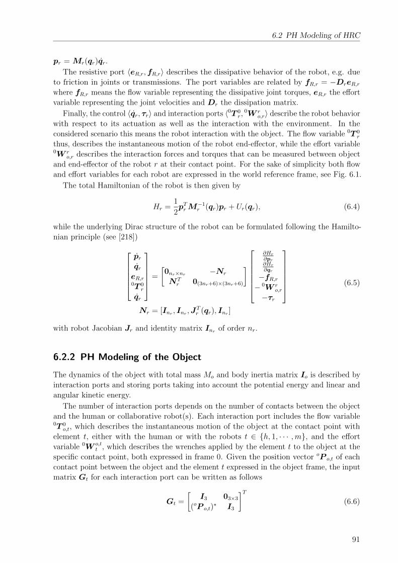
6.2 PH Modeling of HRC
pr = Mr(qr)qr.
The resistive port 〈eR,r,fR,r〉 describes the dissipative behavior of the robot, e.g. due
to friction in joints or transmissions. The port variables are related by fR,r = −DreR,rwhere fR,r means the flow variable representing the dissipative joint torques, eR,r the effort
variable representing the joint velocities and Dr the dissipation matrix.
Finally, the control 〈qr, τr〉 and interaction ports 〈0T 0r,
0W ro,r〉 describe the robot behavior
with respect to its actuation as well as the interaction with the environment. In the
considered scenario this means the robot interaction with the object. The flow variable 0T 0r
thus, describes the instantaneous motion of the robot end-effector, while the effort variable0W r
o,r describes the interaction forces and torques that can be measured between object
and end-effector of the robot r at their contact point. For the sake of simplicity both flow
and effort variables for each robot are expressed in the world reference frame, see Fig. 6.1.
The total Hamiltonian of the robot is then given by
Hr =1
2pTrM
−1r (qr)pr + Ur(qr), (6.4)
while the underlying Dirac structure of the robot can be formulated following the Hamilto-
nian principle (see [218])prqreR,r0T 0
r
qr
=
[0nr×nr −Nr
NTr 0(3nr+6)×(3nr+6)
]
∂Hr
∂pr∂Hr
∂qr
−fR,r− 0W r
o,r
−τr
Nr = [Inr , Inr ,J
Tr (qr), Inr ]
(6.5)
with robot Jacobian Jr and identity matrix Inr of order nr.
6.2.2 PH Modeling of the Object
The dynamics of the object with total mass Mo and body inertia matrix Io is described by
interaction ports and storing ports taking into account the potential energy and linear and
angular kinetic energy.
The number of interaction ports depends on the number of contacts between the object
and the human or collaborative robot(s). Each interaction port includes the flow variable0T 0
o,t, which describes the instantaneous motion of the object at the contact point with
element t, either with the human or with the robots t ∈ {h, 1, · · · ,m}, and the effort
variable 0W o,tt , which describes the wrenches applied by the element t to the object at the
specific contact point, both expressed in frame 0. Given the position vector oP o,t of each
contact point between the object and the element t expressed in the object frame, the input
matrix Gt for each interaction port can be written as follows
Gt =
[I3 03×3
(oP o,t)∗ I3
]T(6.6)
91

6 Energy-Based Supervisory Control for Safety Enhancement
with identity matrix I3, and 3 × 3 skew-symmetric matrix (oP o,t)∗ associated to the
displacement vector oP o,t.
The position xo of the center of mass of the object is the state variable for the storage port
〈xo, ∂Ho
∂xo〉 describing the gravitational energy with the Hamiltonian function Ho = Mog
Txoand g = [0,−g0, 0]T the gravity vector.
The storage ports for the linear kinetic energy 〈po, ∂H∂p0 〉 and angular kinetic energy 〈lo, ∂H∂lo 〉are characterized by their state variables po = Movo for the object’s linear momentum and
lo = Ioωo for the object’s angular momentum. Corresponding Hamiltonian functions for
aforementioned storage ports are presented as 12pToM
−1o po and 1
2lTo I
−1o lo. In above formulas,
vo is the linear velocity of the object, ωo the angular velocity, and Io the inertia tensor of
the object. Please note that assigning two storage ports is performed to be able to explicitly
analyse linear and angular motions of the object independently, although these two ports
could be also combined into one as done e.g. in section 6.2.1.
The total Hamiltonian function of the object is given by
H =1
2pToM
−1o po +
1
2lTo I
−1o lo + (−Mog
Txo). (6.7)
Following the Hamiltonian principle this results in the following formulation of the corre-
sponding Dirac structure
[polo
]xo
0T 0o,1...
0T 0o,m
0T 0o,h
=
[06×6 −No
NTo 0(6m+9)×(6m+9)
]
[∂H∂po∂H∂lo
]∂H∂xo
− 0W o,11
...
− oW o,mm
− oW o,hh
No = [I3,03×3,G1, · · · ,Gm,Gh]
. (6.8)
6.2.3 PH Modeling of the Human
Since the number of degrees of freedom does not affect the procedure of modeling based on
the PH formalism, without loss of generality we consider a nh DOF human arm structure,
which can e.g. include flexion-extension movements in the shoulder, elbow and wrist. The
visco-elasticity of the human skin (or even arm) can also be considered within the compliant
contact model as detailed in section 6.2.4.
Similar to section 6.2.1, an energy storage port corresponding to the arm’s potential
energy, an interaction port representing the dynamical behavior due to the contact between
human and object, and a control port for the joint torques generated by human muscles
are considered. The final PH formulation results in the same structure as (6.2).
92
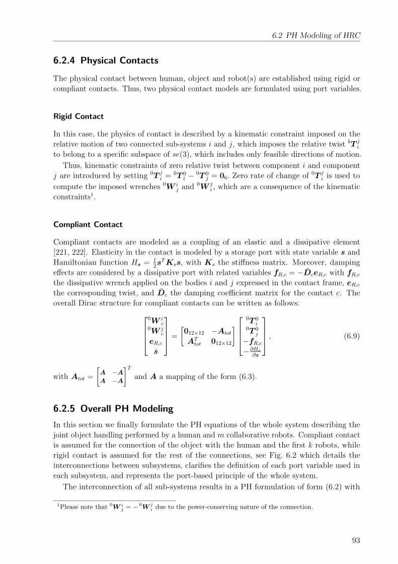
6.2 PH Modeling of HRC
6.2.4 Physical Contacts
The physical contact between human, object and robot(s) are established using rigid or
compliant contacts. Thus, two physical contact models are formulated using port variables.
Rigid Contact
In this case, the physics of contact is described by a kinematic constraint imposed on the
relative motion of two connected sub-systems i and j, which imposes the relative twist bT ji
to belong to a specific subspace of se(3), which includes only feasible directions of motion.
Thus, kinematic constraints of zero relative twist between component i and component
j are introduced by setting 0T ji = 0T 0
i − 0T 0j = 06. Zero rate of change of 0T j
i is used to
compute the imposed wrenches 0W ij and 0W j
i , which are a consequence of the kinematic
constraints1.
Compliant Contact
Compliant contacts are modeled as a coupling of an elastic and a dissipative element
[221, 222]. Elasticity in the contact is modeled by a storage port with state variable s and
Hamiltonian function Hs = 12sTKss, with Ks the stiffness matrix. Moreover, damping
effects are considered by a dissipative port with related variables fR,c = −DceR,c with fR,cthe dissipative wrench applied on the bodies i and j expressed in the contact frame, eR,cthe corresponding twist, and Dc the damping coefficient matrix for the contact c. The
overall Dirac structure for compliant contacts can be written as follows:0W i
c0W j
c
eR,cs
=
[012×12 −Atot
ATtot 012×12
]0T 0
i0T 0
j
−fR,c−∂Hs
∂s
, (6.9)
with Atot =
[A −AA −A
]Tand A a mapping of the form (6.3).
6.2.5 Overall PH Modeling
In this section we finally formulate the PH equations of the whole system describing the
joint object handling performed by a human and m collaborative robots. Compliant contact
is assumed for the connection of the object with the human and the first k robots, while
rigid contact is assumed for the rest of the connections, see Fig. 6.2 which details the
interconnections between subsystems, clarifies the definition of each port variable used in
each subsystem, and represents the port-based principle of the whole system.
The interconnection of all sub-systems results in a PH formulation of form (6.2) with
1Please note that 0W ij = − 0W j
i due to the power-conserving nature of the connection.
93

6 Energy-Based Supervisory Control for Safety Enhancement
R,m
R,m
R,k+1 R,k+1
o,m
o,mm
o,k+1
o,k+1k+1
o,hh
o,h
o,k
o,kk o,1
o,11
o,h
R,1
R,k
R,hR,ch
R,c1
R,ckR,cko,k
R,c1
R,ch R,h
o,1
R,1
R,k
Figure 6.2: Port-based representation of collaborative transportation of an object by a humanand m robots, each with either rigid contact (direct connection) or compliantcontact (represented by (cnt)).
state vector
x =[Po,Xo,Pa,Qa,Sa
]T, and (6.10)
Po =[po; lo
]T, Xo =
[xo]T, Pa =
[ph;p1; · · · ;pm
]T,
Qa =[qh; q1; · · · ; qm
]T, Sa =
[sh; s1; · · · ; sk
]T,
J(x) and R(x) matrices as reported in (6.11) and (6.12),
J =
0 −I 0 0 −BIT 0 0 0 0
0 0 0 −E −F0 0 ET 0 0
BT 0 F T 0 0
, (6.11)
I = [I3 03×3]T ,
B = [−zhGThA
Th ,−z1GT
1AT1 , · · · ,−zkGT
kATk , 0, · · · , 0],
E = I(nh+∑m
r=1 nr),
F = diag(−zhJThATh , −z1JT1 AT
1 , · · · , −zkJTk ATk ),
R =
zhG
ThA
Th DhAhGh +
∑kr=1 zrG
TrA
Tr DrArGr 0 L 0 0
0 0 0 0 0
LT 0 V 0 0
0 0 0 0 0
0 0 0 0 0
, (6.12)
L =[zhG
ThA
Th DhAhJh z1G
T1A
T1 D1A1J1 · · · zkG
TkA
Tk DkAkJk
]V = diag(Dh, D1, · · · ,Dm),
94
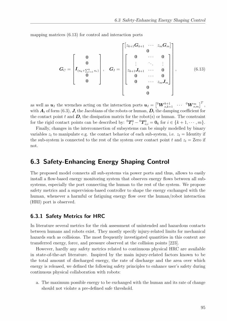
6.3 Safety-Enhancing Energy Shaping Control
mapping matrices (6.13) for control and interaction ports
GC =
0
0
I(nh+∑k
r=1 nr)
0
0
, GI =
[zk+1Gk+1 · · · zmGm
]0
0 · · · 0...
. . ....
zk+1Jk+1 · · · 0
0 · · · 0
0 · · · zmJm
0
0
, (6.13)
as well as uI the wrenches acting on the interaction ports uI =[0W k+1
o,k+1 · · ·0Wm
o,m
]T,
withAt of form (6.3), Ji the Jacobians of the robots or human, Dt the damping coefficient for
the contact point t and Di the dissipation matrix for the robot(s) or human. The constraint
for the rigid contact points can be described by: 0T 0i − 0T 0
o,i = 06 for i ∈ {k + 1, · · · ,m}.Finally, changes in the interconnection of subsystems can be simply modelled by binary
variables zt to manipulate e.g. the contact behavior of each sub-system, i.e. zt = Identity if
the sub-system is connected to the rest of the system over contact point t and zt = Zero if
not.
6.3 Safety-Enhancing Energy Shaping Control
The proposed model connects all sub-systems via power ports and thus, allows to easily
install a flow-based energy monitoring system that observes energy flows between all sub-
systems, especially the port connecting the human to the rest of the system. We propose
safety metrics and a supervision-based controller to shape the energy exchanged with the
human, whenever a harmful or fatiguing energy flow over the human/robot interaction
(HRI) port is observed.
6.3.1 Safety Metrics for HRC
In literature several metrics for the risk assessment of unintended and hazardous contacts
between humans and robots exist. They mostly specify injury-related limits for mechanical
hazards such as collisions. The most frequently investigated quantities in this context are
transferred energy, force, and pressure observed at the collision points [223].
However, hardly any safety metrics related to continuous physical HRC are available
in state-of-the-art literature. Inspired by the main injury-related factors known to be
the total amount of discharged energy, the rate of discharge and the area over which
energy is released, we defined the following safety principles to enhance user’s safety during
continuous physical collaboration with robots:
a. The maximum possible energy to be exchanged with the human and its rate of change
should not violate a pre-defined safe threshold.
95

6 Energy-Based Supervisory Control for Safety Enhancement
b. The pre-defined safe threshold should be adaptive based on user fatigue to decrease
the risk of muscle injury.
Hazardous situations during HRC can be the consequence of unpredictable robot behavior
resulting from e.g. false sensor readings or actuator failures. They may lead to a fast change
of total energy or rate of change of energy exchanged with the human. Therefore, keeping
the total energy in the system below an acceptable limit (Htot < Hmax) is a first step to
improve safety. Such upper safety limits are the results of experimental energy-related
injury analyses performed in literature, see [224, 225] for collision-based results on cranial
bones and neck bones. Also the rate of change of energy, namely power, passing through the
HRI port should be bounded (Ph < Pmax). As currently ONLY metrics for safety evaluation
during impacts are available, we use Pmax found in impact studies, see e.g. [223, 226].
Finally, human fatigue can be considered a further risk factor as muscle injuries may
result from over-straining (see [227–230]). Therefore, we propose the aforementioned upper
thresholds for energy and power to be not only functions of injury-related measures, but
also of user fatigue.
6.3.2 Control Design
The safety controller is represented as an independent PH system that operates on the basis
of energetic information and energy flows in the system. The controller should interfere
as little as possible with the execution of the task (e.g. transporting an object from an
initial to a final position), while implementing the aforementioned safety principles without
explicit knowledge of the human sub-system. Then the controller is designed based on
the information provided from the port-based modeling of the system interacting with the
human.
Nominal Controller
As the coordination of multiple robots is beyond the scope of this thesis and our aim is to
illustrate the main principle of the proposed safety controller, without loss of generality we
reduced the control problem to the tracking of pre-determined trajectories starting at an
initial and ending at a final robot configuration. The desired equilibrium state for robot
r is considered (xr,Pr) = (xdes,r,0), where xdes,r is the desired robot configuration. As
controller we chose
ur = Kp,rxe,r +Kd,rxe,r (6.14)
with a global and unique minimum at the desired equilibrium and xe,r = xdes,r − xr the
robot configuration error. The stiffness Kp,r connects the desired equilibrium and the
current robot configuration, while the additional damping factor Kd,r helps stabilizing the
controlled PH system.
Safety-Enhancing Adaptive Controller
A safe system behavior during HRC is achieved by proper tuning of the parameters Kp and
Kd of the nominal controller for all robots based on safety principles defined in section 6.3.1.
96

6.3 Safety-Enhancing Energy Shaping Control
The controlled system interacting with the human includes m robots and the object
with a total energy of
Htot =m∑r=1
1
2xTe,rKp,rxe,r +
m∑r=1
Hr +Ho (6.15)
where Kp,r is a diagonal matrix representing the stiffness factor in the controller of robot r,
and Hr and Ho are the Hamiltonian functions of the robot r and the object, respectively.
Considering Hmax to be the upper safe value of Htot, (6.15) can be re-written as follows:
Heff = QKp = Hmax −m∑r=1
Hr −Ho (6.16)
where Q = [xTe,1xe,1, ...,xTe,mxe,m] and Kp = [Kp,1, ...,Kp,m]T . Thus, considering Hmax to
be the limit of the total energy, the stiffness factors for each robot controller are selected as
follows:
Kp =
{Kp Htot ≤ Hmax
Q#Heff Htot > Hmax(6.17)
with Q# the Pseudoinverse of Q. Please note that also a weighted Pseudoinverse could be
used instead.
Next, the upper limit for the rate of change of the energy flow needs to be guaranteed.
The power conservation property of the Dirac structure implies that the change in the
stored energy of a system equals the sum of the power provided by the external ports and
dissipative ports:
eTRfR + eTCfC + eTI fI = −eTSfS = H. (6.18)
Applying this logic to the system, the total power transferred over the HRI port is written
as:
Ph = −m∑r=1
Pc,r +m∑r=1
Hr + Ho, with (6.19)
Pc,r = (Kp,rxe,r −Kd,rxe,r)T xe,r
where Pc,r is the power injected by the controller of robot r. Considering the maximum
power applied to the human to be Pmax we finally get
Peff = V Kd = Pmax +m∑r=1
xTe,iKp,rxe,r −m∑r=1
Hr − Ho (6.20)
with V = [xTe,1xe,1, ..., xTe,mxe,m] and Kd = [Kd,1, ...,Kd,m]T . In order to consider the upper
and lower limits for power exchange between the human and the rest of the system, the
sign of Pmax is selected as follows
Pmax =
{−Pmax Ph ≤ −Pmax,Pmax Ph > Pmax.
(6.21)
97

6 Energy-Based Supervisory Control for Safety Enhancement
The damping factors for each robot controller are finally tuned to avoid unsafe rates of
change of energy to be discharged over the HRI port, resulting in:
Kd =
{Kd |Ph| ≤ |Pmax|,V #Peff else,
(6.22)
with V # the Pseudoinverse of V .
Please note that the values ofKp will never become negative and thus, result in instability,
as long as Hmax is reasonably chosen. This can be easily checked by analyzing (6.17),
where Q is positive definite and thus, only a negative value of Heff can lead to a negative
Kp. However, Heff is computed based on (6.16), which will never become negative as long
as Hmax, is larger than the two other terms in (6.16). This is always the case because a
reduction of Heff would result in a reduction of Kp, which again would reduce∑m
r=1Hr
and thus, would increase Heff again. A similar logic can also be applied for the adaptation
of the Kd gain.
Overloading muscles may result in muscle pain, or even strain injury. Thus, apart from
preventing dangerous robot behavior, we further aim at reducing the risk of muscle injury
through adaptation of the power applied to the human based on estimation of the fatigue.
Taking into account relations of fatigue and work, see [231, 232], a probability for human
muscle fatigue is derived by integrating the energy flow over the HRI port,
pfatigue =
∫Ph dt
Wh,max
, (6.23)
with Wh,max the total performed work at which human muscle fatigue starts to be observed
[231–233].
To take fatigue into account in the controller design, we control the energy flow over the
HRI port by online adapting the value of Pmax according to the level of muscle fatigue:
Pmax = pfatiguePmin + (1− pfatigue)Pmax, (6.24)
with Pmin and Pmax being the minimum and, respectively, the maximum human contribution
to the task.
Passive Implementation
While in the previous sections we discussed few aspects of stability of the proposed safety-
enhancing control system, here we introduce an energy-based procedure for a passive
implementation of the controller (6.14) with variable damping and stiffness terms. As the
human is a complex and time-varying dynamic system, it’s difficult to be studied directly
within an overall system stability analysis requiring accurate human models. We propose an
approach that guarantees passivity of the system interacting with the human. This ensures
that the system interacting with the human will not lead to an unstable situation due to
the behavior of the robot controller at least as far as it is interacting with other passive
systems (assuming here that the human will behave passively). Currently, the variation of
the damping term in the proposed controller in section 6.3.2 may result in the violation
98
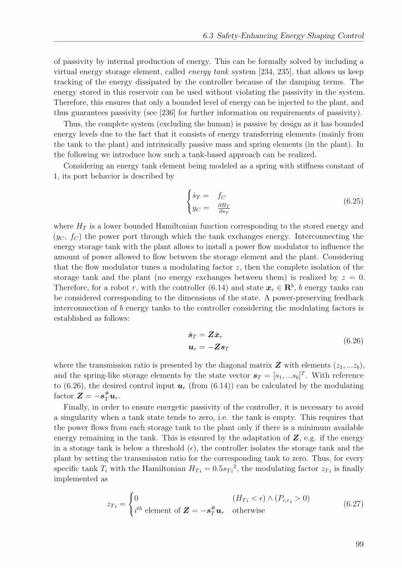
6.3 Safety-Enhancing Energy Shaping Control
of passivity by internal production of energy. This can be formally solved by including a
virtual energy storage element, called energy tank system [234, 235], that allows us keep
tracking of the energy dissipated by the controller because of the damping terms. The
energy stored in this reservoir can be used without violating the passivity in the system.
Therefore, this ensures that only a bounded level of energy can be injected to the plant, and
thus guarantees passivity (see [236] for further information on requirements of passivity).
Thus, the complete system (excluding the human) is passive by design as it has bounded
energy levels due to the fact that it consists of energy transferring elements (mainly from
the tank to the plant) and intrinsically passive mass and spring elements (in the plant). In
the following we introduce how such a tank-based approach can be realized.
Considering an energy tank element being modeled as a spring with stiffness constant of
1, its port behavior is described by {sT = fC
yC = ∂HT
∂sT
(6.25)
where HT is a lower bounded Hamiltonian function corresponding to the stored energy and
(yC , fC) the power port through which the tank exchanges energy. Interconnecting the
energy storage tank with the plant allows to install a power flow modulator to influence the
amount of power allowed to flow between the storage element and the plant. Considering
that the flow modulator tunes a modulating factor z, then the complete isolation of the
storage tank and the plant (no energy exchanges between them) is realized by z = 0.
Therefore, for a robot r, with the controller (6.14) and state xr ∈ Rb, b energy tanks can
be considered corresponding to the dimensions of the state. A power-preserving feedback
interconnection of b energy tanks to the controller considering the modulating factors is
established as follows:
sT = Zxr
ur = −ZsT(6.26)
where the transmission ratio is presented by the diagonal matrix Z with elements (z1, ...zb),
and the spring-like storage elements by the state vector sT = [s1, ...sb]T . With reference
to (6.26), the desired control input ur (from (6.14)) can be calculated by the modulating
factor Z = −s#T ur.Finally, in order to ensure energetic passivity of the controller, it is necessary to avoid
a singularity when a tank state tends to zero, i.e. the tank is empty. This requires that
the power flows from each storage tank to the plant only if there is a minimum available
energy remaining in the tank. This is ensured by the adaptation of Z, e.g. if the energy
in a storage tank is below a threshold (ε), the controller isolates the storage tank and the
plant by setting the transmission ratio for the corresponding tank to zero. Thus, for every
specific tank Ti with the Hamiltonian HT i = 0.5sT i2, the modulating factor zT i is finally
implemented as
zT i =
{0 (HT i < ε) ∧ (Pc,ri > 0)
ith element of Z = −s#T ur otherwise(6.27)
99

6 Energy-Based Supervisory Control for Safety Enhancement
where ε is the minimum energy threshold considered for tank i and Pc,ri the power flowing
from the controller to the plant related to the state that the tank is specified for (that can
be calculated similar to (6.19)).
To avoid an excess of energy stored in the tanks that would allow implementation of
practically unstable behaviors in the system, see the reasons reported in [237], it is wise to
disable the charging of the tanks when their energies are bigger than a suitable upper bound.
This bounded level of energy in the tanks should be defined specific to each application
and task to be accomplished as well as a possible estimation of the maximum energy that
can be injected by subsystems (e.g. considering the possible force that can be applied by
the human).
6.4 Results
We present simulation results for the port-Hamiltonian model of the considered HRC task,
including also the proposed energy-based safety controller.
6.4.1 Simulation of the HRC Model
Validation of the modeling approach was performed on an academic test scenario considering
the collaborative object manipulation by a 2 DOF serial robot manipulator with revolute
joints and a 2 DOF human arm with shoulder and elbow joints moving in the vertical
plane. The total mass and inertia tensor of the object were considered to be Mo = 5 kg
and Io = diag(0.006, 0.04, 0.04) [kgm2] respectively, while the dynamic and geometric
parameters of the robot were assumed as follows: link lengths l1,r = l2,r = 1 m, mass and
inertia of the segments m1,r = m2,r = 1 kg and I1,r = I2,r = 0.084 kgm2. The friction
in the joints was neglected for the sake of simplicity. For the human arm the following
values were assumed for simulation: m1,h = 1.4, m2,h = 1.1 kg, l1,h = 0.3, l2,h = 0.33 m,
and I1,h = 0.025, I2,h = 0.045 kgm2 and Kp,h = diag(100, 100) [N/m], Kd,h = diag(10, 10)
[N·s/m].
Figure 6.3 illustrates the energetic behavior of each sub-system during the experiment.
Four different phases were considered: (a) non-contact initial condition from initial to time
equal to 1 s, (b) approaching the object between 1 s and 4.8 s and, (c) establishing contact at
4.8 s and keeping the current configuration to 5 s, (d) transporting the object to the desired
position from 5 s to the end. Constant stiffness and damping factors Kp = diag(2000, 2000)
[N/m] and Kd = diag(100, 100) [N·s//m] were considered. In phase (c) contact between
human-object and robot-object is established by simply activating the corresponding
contact variables. The three top plots show a good trajectory tracking performance since
the reference positions, which are defined for human and robot independently, are well
followed using the aforementioned controller. The Hamiltonian of each sub-system, as well
as the power exchanged between them, is monitored thanks to the port-based modeling.
For example, the transferred powers Ph and Pr are zero before establishing connection,
while their value after connection to the object represents their injected or absorbed power
during task execution. The value of the power exchanged over the robot-object interaction
point (Pr) is almost three times bigger than the power exchanged over the human-object
100

6.4 Results
00.5
11.5
(a) (b) (c) (d)
xr [m]
yr [m]
0 1 2 3 4 5 6 7 8 9
1
2xh [m]
yh [m]
1
1.5xo [m]
yo [m]
10
15Hr [J]
40
45
50Ho [J]
20
30
40Hh [J]
024 Hc [J]
10
20
0
2
4Ph [W]
0 1 2 3 4 5 6 7 8 910
5
0
time [s]
Pr [W]
HT x [J]
HT y [J]
Figure 6.3: Evaluation of the energy-based HRC model. In the first two top plots, dashed redlines show the reference positions and solid lines show obtained values. The fourphases (a), (b), (c) and (d) are separated by dotted gray lines.
interaction port (Pr) and thus, indicates a larger contribution of the robot than the human
to the execution of the task. Please consider that the positive value for the human power
corresponds to the power transferred from the object to the human. The initial change in
the Hamiltonian of the robot and human during phase (b) is due to movements towards
the obstacle, while further changes during phase (d) are because of transporting the object.
Moreover, the behavior of the tank energies (HT x, HT y) over time shows their recharging
due to the dissipated power of the controller. The charging of tanks mainly happens in two
time intervals of (a) and (d) when parts of the energy of the robot controller are dissipated
due to its damping terms. The tank energies were neither discharged nor depleted (no
decrease of energy is found in the energy profiles), thus confirming passivity of the control
system, which is expected when the controller uses constant values for its damping and
stiffness parameters. Finally, slow gradual changes in the Hamiltonian of the object can be
explained by changes of its potential energy since it was transferred to a higher position.
101

6 Energy-Based Supervisory Control for Safety Enhancement
0.81
1.2
xr [m]yr [m]
1
1.5
xo [m]yo [m]
55606570
Htot [J]
0102030
Ph [W]
600
800
1000
Kp
0 0.5 1 1.5 2 2.5100
120
time [s]
Kd
10
15
HT x [J]HT y [J]
Figure 6.4: Validation of energy-based adaptive shared controller. Solid blue and black linesshow signals using nominal controller, dashed red lines show signals using safety-enhancing adaptive controller and green lines in the two middle plots show theconsidered safety thresholds.
6.4.2 Validation of the Safety-Enhancing Control Approach
A trajectory tracking task was considered, and the following two scenarios were studied to
validate the safety-enhancing controller design proposed in previous sections. In the first
scenario, we evaluate the robot behavior while satisfying aforementioned safety criteria,
and in the second scenario we focus on the adaptation of the robot actions based on the
estimated human fatigue.
Scenario I
The human and the robot transport the object from an initial to a final configuration,
while the robot avoids a dynamic obstacle placed very close to the path and suddenly
appearing at time 0.8 s to 1.3 s.2 The system performance for cases with and without safety
controller is depicted in Fig. 6.4 with Hmax = 65 J, Pmax = 15 W, Kp = diag(1000, 1000)
[N/m] and Kd = diag(100, 100) [N·s/m]. Looking at the results for the case without safety
2Please note that collision avoidance during HRC is out of focus of this thesis and the case of a suddenlyappearing obstacle is used as representative example of many other unpredictable and hazardoussituations that can happen during HRC.
102
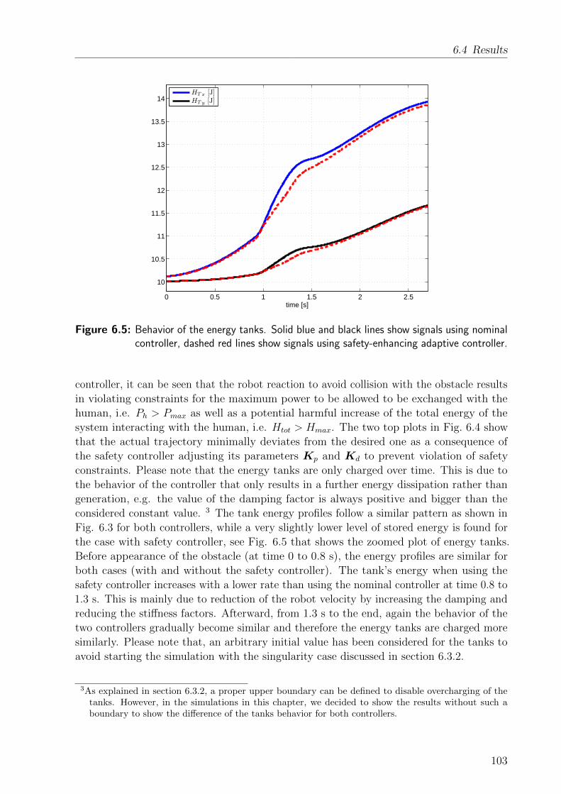
6.4 Results
0 0.5 1 1.5 2 2.5
10
10.5
11
11.5
12
12.5
13
13.5
14
time [s]
HT x [J]HT y [J]
Figure 6.5: Behavior of the energy tanks. Solid blue and black lines show signals using nominalcontroller, dashed red lines show signals using safety-enhancing adaptive controller.
controller, it can be seen that the robot reaction to avoid collision with the obstacle results
in violating constraints for the maximum power to be allowed to be exchanged with the
human, i.e. Ph > Pmax as well as a potential harmful increase of the total energy of the
system interacting with the human, i.e. Htot > Hmax. The two top plots in Fig. 6.4 show
that the actual trajectory minimally deviates from the desired one as a consequence of
the safety controller adjusting its parameters Kp and Kd to prevent violation of safety
constraints. Please note that the energy tanks are only charged over time. This is due to
the behavior of the controller that only results in a further energy dissipation rather than
generation, e.g. the value of the damping factor is always positive and bigger than the
considered constant value. 3 The tank energy profiles follow a similar pattern as shown in
Fig. 6.3 for both controllers, while a very slightly lower level of stored energy is found for
the case with safety controller, see Fig. 6.5 that shows the zoomed plot of energy tanks.
Before appearance of the obstacle (at time 0 to 0.8 s), the energy profiles are similar for
both cases (with and without the safety controller). The tank’s energy when using the
safety controller increases with a lower rate than using the nominal controller at time 0.8 to
1.3 s. This is mainly due to reduction of the robot velocity by increasing the damping and
reducing the stiffness factors. Afterward, from 1.3 s to the end, again the behavior of the
two controllers gradually become similar and therefore the energy tanks are charged more
similarly. Please note that, an arbitrary initial value has been considered for the tanks to
avoid starting the simulation with the singularity case discussed in section 6.3.2.
3As explained in section 6.3.2, a proper upper boundary can be defined to disable overcharging of thetanks. However, in the simulations in this chapter, we decided to show the results without such aboundary to show the difference of the tanks behavior for both controllers.
103

6 Energy-Based Supervisory Control for Safety Enhancement
0.8
1
1.2 xr [m]yr [m]
1
1.5xo [m]yo [m]
20
40 HT x [J]HT y [J]
556065
Htot [J]
0
5
10Ph [W]
0
0.5
1Pf atigue
0 5 10 15 20 25 30100
150
200
time [s]
K d
27 27.5 28
61
62
63
Figure 6.6: Validation of energy-based adaptive shared controller for user’s fatigue reduction.Solid blue and black lines show signals using nominal controller, dashed red linesshow signals using the safety-enhancing adaptive controller and the green line inthe fourth plot shows the considered adaptive safety threshold.
Scenario II
A repetitive task of object transportation is studied, which allows to observe an increasing
level of human fatigue. We considered Phigh = 8.3 W and Plow = 5 W. As can be observed
in Fig. 6.6, the control parameters are adjusted automatically to prevent extra power
applied to the human if the estimated user’s fatigue increases. In both cases, with and
without safety controller, the system tracks well the desired trajectory as depicted in
the two top plots. While this results in similar profiles for the total energy Htot, their
differences have been illustrated by two zoomed plots corresponding to the instances that
the adaptation law is activated. In these instances, Htot is slightly bigger for the case
of using the safety-enhancing controller since the robot system takes over parts of the
task of the human (the power exchanged in the human port is decreased, see Ph profile,
while the object is following the same trajectory). Moreover, with increasing user’s fatigue,
the maximum allowed power to be transferred over the human-object interaction port is
reduced, which results in an increase of Kd to prevent the violation of safety constraints.
For illustration purposes, a relatively low value for Wh,max = 1200 J was considered, which
resulted in a rather fast increase of fatigue. The energy tanks also behave similarly to the
previous simulations and keep storing the dissipated energy of the controller.
104
6.5 Summary and Discussion
6.5 Summary and Discussion
Robotics research is progressing towards physical interaction between humans and robots,
with multiple potential applications not only in rehabilitation and assistive robotics, but
also in industry (e.g. robot co-workers). Close interaction of a human with robots demands
for proper control approaches so as to enhance the safety of the user. However, while
collision detection and contact-related injury reduction in physical human-robot interaction
has been studied intensively, safety issues in physical human-robot collaboration (pHRC)
with continuous coupling of human and robot(s) (which is a common case of assistance
robots) has received little attention so far. This chapter for the first time proposes an energy
monitoring and control system that supervises energy flows among the different subsystems
involved in pHRC and shapes them to improve human safety whenever an unsafe situation
is about to happen. A general pHRC task is considered and further described using bond
graphs and energy flows through ports to cover the different, continuous and time-varying
contact situations that arise in such scenarios. Moreover, a novel monitoring system was
designed that observes energy flows between sub-systems, with a compliance controller that
shapes these flows so as to enhance human safety.
While a priori information was used for the object dynamics within the considered
pHRC task, in particular, an on-line identification scheme would be more appropriate which
can be considered as a possible future direction for practical implementation as well as
experiments with real robots. Nonetheless, the proposed approach relies on power and
energy flows and only required to monitor and bound such physical quantities, rather than
canceling dynamic terms by control. In this sense, the presented controller is intrinsically
more robust to uncertainties. However, dependence of accurate dynamic models of the
sub-systems (except the human as its direct usage has been excluded in the design of the
safety-enhancing controller) is the main restriction of the proposed approach.
As currently, only metrics for safety evaluation during impacts are available, in this
work the thresholds for maximum exchangeable power and energy were specified from
impact studies. However, future research can focus on deriving proper new thresholds
for continuous interaction taking the specific human configuration into account. Finally,
investigation of other safety metrics that consider the continuous nature of tasks and the
actual configuration of bodies can be studied in future.
The proposed safety-enhancing concept in this chapter can be considered complementary
to any of the developed controllers presented in the last three chapters, e.g. to shape the
energy applied to the human and to keep its magnitude and rate of change within safe
boundaries during STS or fall prevention. However, an immediate future work can extend
the proposed modeling and control approaches for a mobility assistance robot including
actuated arms.
105

7 Conclusion and Future Work
7.1 Summary and Concluding Remarks
Mobility problems can impede independent living and are prevalent in the elderly population.
Mobility assistance robots (MARs) can help in overcoming this situation by incorporating
features like sit-to-stand assistance, walking and navigation assistance in indoor and outdoor
environments, posture control and fall prevention. However, they also come with challenges
in terms of acceptability by the users, adaptability to users and environment as well as safety
due to their close interaction with humans, more specifically the elderly or patients with
cognitive and/or physical impairments. This thesis has proposed approaches to design novel
and human-inspired controllers for mobility assistance robots. Achieving safe, natural, and
user and environment-adaptive robot behavior were considered to be the main challenges
in the control design.
The research directions of this thesis were formulated based on an overview of the current
state of the art MAR functionalities presented in chapter 2. This literature review of a total
number of 27 rollator-type MARs showed that most available systems are active, based
on four wheels and having a non-holonomic kinematics. Moreover, main functionalities of
MARs were identified as sit-to-stand (STS) and stand-to-sit transfer assistance, walking
assistance and health monitoring. This thesis therefore focused on the development of the
control approaches for three commonly demanded modes of STS and walking as well as
human’s fall prevention due to its crucial importance.
In terms of STS transfer assistance, chapter 3 proposed biologically-inspired and optimal
assistance approaches to be provided by MARs. This chapter extended the state of the
art on STS assistance with respect to the following aspects: i) mathematical modeling
of the human’s STS transfers and exploiting their underlying principles, ii) extension
of the obtained models to derive optimal and biologically-inspired assistive strategies to
be provided to the users, and iii) intensive evaluation by real end-users. Modeling of
assisted and unassisted human STS transfers were formulated as an optimal feedback
control formulation. Compared to previous work based on SQP approaches, we based
our optimization on Differential Dynamic Programming that has been shown to be a
powerful tool in studying biological movements. It has allowed us to obtain an optimal
solution with respect to a defined cost function and considers the nonlinearity of human
biomechanics as well as physical constraints, which are naturally incorporated into the
optimization framework. It further showed potential for future online implementation.
The model was extended with external forces and torques. Optimal assistive STS transfer
strategies were determined considering two types of assistance classes and weaknesses.
The resulting optimal assistive trajectories were calculated and implemented on a robotic
mobility assistant. The assistive STS transfer approach was finally evaluated within an
intensive user-study of elderly subjects. Results showed a high user satisfaction as well
106
7.1 Summary and Concluding Remarks
as excellent success rate for all participants indicating the effectiveness of the proposed
assistance optimization approaches.
The control design of MARs during walking (as the second considered operational mode)
was studied in chapter 4. The novelty of this chapter focuses on two aspects: i) to develop
an integrated shared control approach that helps the user by providing sensorial, cognitive
and physical assistance, and ii) to employ the human’s decision making mechanism as the
key component in the adaptation laws of the robot controller. The integrated shared control
architecture distinguishes between short-term adaptations providing a) cognitive assistance
to support the user to follow a desired path towards a predefined destination and b) sensorial
assistance to avoid collisions with obstacles and to allow for an intentional approach of
them. Furthermore, it considered a long-term adaptation of c) the overall assistance
based on long-term user performance and observed fatigue. To achieve an intuitive and
human-like adaptation policy of the provided assistance, a decision-making model explored
in cognitive science, the Drift-Diffusion model, was employed. The effectiveness of the
proposed architecture evaluated by means of technical experiments as well as a user-study
with elderly people. Obtained results indicated that the required functionalities can be
realized with the proposed decision-making algorithm showing a general high potential of
the proposed adaptive shared control architecture for MARs.
Human balance recovery and fall prevention was discussed in chapter 5, where for the
first time a fall prevention approach was proposed for a mobility assistance robot equipped
with a pair of actuated arms. The algorithm evaluated the user’s Extrapolated Center of
Mass (XCOM) and determined the required supportive forces to be provided to the user for
fall prevention. Moreover, a compliant robot controller was proposed to realize the required
forces for fall prevention. Results of this chapter revealed that the use of XCOM is an
appropriate choice for human’s balance determination and fall prevention control design as
its computation is easier than the ZMP or COP, and its reaction to human’s fall is faster
than COM. The later allows for a faster robot reaction and therefore prevention of the
human’s falls as soon as it is about to happen.
Safety aspects are the crucial requirement in the control design and were considered
for each mode of operation. In chapter 3 it was focused on by considering the balance
criteria aiming at avoiding human’s fall during STS transfers, in chapter 4 by developing as
passive as possible assistive strategies, and in chapter 5 by developing an optimal human
fall prevention approach. Moreover, the safety aspect was further emphasized in chapter
6 by the realizing of a general and complementary controller that aimed to supervise the
behavior of the specific control unit in the specified mode of operation and reshape the
robot’s behavior to enhance the user’s safety if an unsafe situation is about to happen. The
safety approach presented in this chapter is general and can be applied not only to assistance
devices, but also to other collaborative robots, with multiple potential applications, e.g.
robot co-workers in industry.
A major contribution here was to develop an energy-flow and port-based model for a
general pHRC scenario taking the different and time-varying contact situations that are
typical for such a scenario into account. Based on this model, a novel energy monitoring
and adaptive controller was proposed that observes energy flows between all sub-systems
and that shapes them accordingly to guarantee human safety. Safety metrics were defined
107

7 Conclusion and Future Work
considering the maximum energy that is allowed to be exchanged with humans and the
maximum rate of change of it, along with measures that take human fatigue into account.
In summary, the ideas, concepts and approaches developed in this dissertation significantly
advance the state of the art in the control design of assistance robots taking into account
safety, intuitiveness and acceptability as well as user and environment-adaptation.
7.2 Perspectives
The research field of mobility assistance robots is of a highly interdisciplinary nature.
By combining the research fields of cognitive science and motor control, with computer
science and robotics engineering, the work in this thesis provides a solid ground for future
interdisciplinary research for the further advancement of the control design of MARs. The
topics addressed in this dissertation also motivate a number of interesting future research
directions, as drafted in the following:
• Developement of systems and functionalities of mobility assistance robots:
Important points for the future development of rollator-type mobility assistance robots
will be to advance the robots not only from a hardware perspective, but also from
a software, and thus, functionality perspective. In terms of hardware and system
design, sensors like GPS, Kinect, 3D laser, and tactile sensors could be further
explored along with independent actuation systems for handles providing STS transfer
assistance. In terms of functionalities, more weight could be given to STS transfer
support, fall prevention, health monitoring, and extra functionalities involving more
advanced human-system interfaces. Although explored human-machine interfaces are
so far mainly limited to touch-screens and speech interfaces, nonverbal interaction
via gesture and mimics with the systems can be a target for future advancements.
Though these human-machine systems are generally an interesting research topic,
their benefits in the context of mobility assistance robots for the elderly has still to
be proven as cognitive disabilities typically may reduce the capability of the elderly
to communicate via gestures and mimics.
• Unified control system for different operational modes: Different phases of
human motion and robot operational modes call for different robot controllers to be
implemented, as considered in this thesis for three main modes. Automatic switching
between the control modes was out of focus of this thesis and has received very little
attention in literature. So far, only hard switching between different controllers has
been performed by either using some predefined thresholds in measurement data,
or evaluating user inputs provided via touch screens or voice interfaces. However,
intelligent mechanisms for switching the robot controllers can be investigated. This
could advance the development of a sophisticated MAR providing assistance in
different modes of operation based on the user state and needs. In case of multiple
switching between controllers, this can also be studied from a control theory perceptive
to prove the overall stability of the hybrid and switched systems.
108

7.2 Perspectives
• Sit-to-stand transfers modeling and optimal assistance: While in this thesis
a basic human biomechanical model has been studied, future work can focus on
considering more complex three-dimensional human dynamic models, even with
direct muscle control. This could result in a deeper understanding of the underlying
principles. Moreover, it will allow to better understand the contribution of the human
muscles and thus, to better address muscle weaknesses during STS transfers allowing
to take muscle weaknesses into account through personalized user assistance.
• Human articulated tracking for walking and fall prevention assistance:
Advanced robot controllers require information about the actual human posture
and thus, articulated tracking functionalities have to be implemented on the robot.
Although in literature basic approaches for articulated tracking were proposed with
the help of a small number of laser scanners that scanned the user at different heights
of the body and thus, allowed us to only roughly estimate the actual human posture,
further investation on available sensors like 3D laser scanners and Kinect may help
for a better human posture determination. This could provide more sophisticated
information and therefore improve the development of the user-adaptive approaches
for both walking and human fall prevention assistance.
• Safety: Safety will become one of the critical factors to bring MARs on the market and
suitable for daily usage by the end-users. In this thesis, safety was considered during
walking by concentration on passive support, while it was evaluated mainly in terms
of posture stability measures for STS transfers and human fall prevention assistance.
In this respect, a more elaborate safety analysis that goes beyond classical posture
stability measures and includes the definition of posture-dependent safe states and
safe robot behaviors can be investigated. Moreover, this thesis particularly considered
the allowed energy exchange between user and robot and proposed approaches to
limit the energy of the robots and the power transferred to the human to enhance the
safety of the system. Future directions could further investigate other factors such as
environmentally constrained configurations of the human body next to constraints
originating from the task itself in order to eliminate possibilities of injuries in HRC.
Moreover, investigation of other safety metrics and requirements that consider the
continuous nature of collaborative and assistive tasks and the actual configuration of
bodies can be studied in future.
The main idea and individual concepts of this thesis are also expected to motivate further
developments towards user-oriented, biologically-inspired and context-specific assistive
approaches that consider user’s safety as well as natural and adaptive robot behavior.
109

A Anthropomorphic Data of Participants inSTS Model Evaluations
Two tables reporting the body measurements of the healthy and elderly participants in the
validation of the STS transfer model are reported as follows.
Table A.1: Anthropometric data of healthy subjects participating in the STS model validation
subject age weight [kg] height [m]S1 26 74 1.72S2 25 80 1.80S3 29 70 1.83
Table A.2: Anthropometric data, cognitive and motor impairment level of elderly subjectsparticipating in the STS model validation.
subject age weight height Cognitive Motor[kg] [m] impairment level impairment level
S1 80 64 1.53 no impairment moderateS2 77 60 1.59 no impairment moderateS3 77 69 1.75 no impairment moderateS4 80 89 1.64 moderate moderateS5 85 56 1.49 no impairment moderateS6 80 70 1.40 severe moderateS7 75 74 1.56 no impairment moderateS8 85 85 1.70 moderate moderateS9 81 61 1.78 moderate moderate
110

B Optimal Feedback Control
Complementary information for Differential dynamic programming (DDP) approach is
presented in this section. DDP first proposed in [137] and recently reformulated by [138]
is used to solve the optimal control problem cast in the chapter 3. DDP iteratively and
quadratically approximates the costs and the nonlinear system dynamics around the current
trajectory where an approximately optimal control law in affine form is considered for the
approximated system that enforces formulated control constraints. The algorithm starts
an initial guess of the control sequence (in our specific STS transfer problem we consider
pure gravity compensating forces), which is then iteratively improved with respect to the
formulated cost function. The iterative approach is implemented as describes followings.
First, the cost function is time-discretized
c(x(k), τ (k)) =N−1∑k=0
( 6∑i=1
Ci(x(k), τ (k)))
∆t (B.1)
with N = T/∆t. Then, each iteration starts with an open loop control sequence τkthat is applied to the deterministic nonlinear and discretized forward dynamics xk+1 =
xk + ∆tf(xk, τk) using standard Euler integration at sample k. Then, the dynamics and
the cost function are quadratically approximated in the vicinity of the current trajectory.
Both aforementioned approximations are expressed in terms of state and control deviations,
i.e. δxk = xk − xk and δτk = τk − τk, and are computed as follows,
δxk+1 = (I + ∆tfx)δxk + ∆t(fτ δτk + δτ Tk fτxδxk)
+ 0.5∆t(δxTk fxxδxk + δτ Tk f
ττ δτk) (B.2)
c(δx, δτ ) = δxTk cx + δτ Tk c
τ + δτ Tk cτxδxk
+ 0.5(δxTk cxxδxk + δτ Tk c
ττ δτk) (B.3)
with funcvars the partial derivative of function func with respect to variables ordered by
vars and all the partial derivatives are obtained at (xk, τk).
At each moment k, the cost for the optimal control of the system from the current state
xk to the final state xN is defined by:
v(xk) = φfinal(xN) + ck(xi, τ∗i ), (B.4)
where τ ∗i is the optimal control decision. This local approximation of the original optimal
control problem can then be efficiently solved by evaluating the Hamilton-Jacobi-Bellman
111

B Optimal Feedback Control
equation
vk(δx) = δxTkPk +1
2δxTkQkδxk + δτ ∗Tk Rk (B.5)
+1
2δτ ∗Tk Skδτ
∗k + δτ ∗Tk Tkδxk
where
Pk = ∆t cx + (I + ∆tfx)vxk+1
Rk = ∆t (cτ + fτvxk+1)
Qk = ∆t cxx + (I + ∆tfx)vxxk+1(I + ∆t(fx)T )
+ ∆tfxxvxk+1
Sk = ∆t (cττ + fτvxxk+1(fτ )T ) + ∆tfττvxk+1
Tk = ∆t cτx + (∆t(fτ )T )vxxk+1(I + ∆t(fx)T )
+ ∆tfτxvxk+1.
Minimizing the right side of (B.5) with respect to δτk determines the optimal control
policy as follows,
δτ ∗k = −S−1k Rk − S−1k Tkδxk. (B.6)
The resulting control law is of affine form δτ ∗k = lk + Lkδxkwith an open loop term
(lk = −S−1k Rk) and a feedback term (Lkδxk = −S−1k Tkδxk). Additional control constraints
are taken into account by enforcing the open loop terms to lie inside of a constrained
boundary. If the control constraint is violated, the open loop term is determined to either
guide the optimal control inside of the boundary or at least to stay within it by considering,
lk = min(max(τmax, τk + lk), τmin). (B.7)
For each iteration i the approximate optimal control sequence τ (i+1)k is finally obtained
by adding the newly calculated corrective control term and the control term of the last
iteration τ (i+1)k = δτ
(i)k + τ
(i)k , and then the new nominal state and control trajectories are
computed using the dynamic equations of the system. 1
1 [138, 238] proposed different improvements to the iterative LQG method including the invertabilityproblem of Sk that have been also considered in the above-mentioned DDP implementation, but arenot explicitly mentioned here because of space limitations.
112

Bibliography
Bibliography
[1] UN Report. United nations report: World population prospects, the
2015 revision. Analytical Report, United Nations New York, http :
//esa.un.org/unpd/wpp/publications/files/keyf indingswpp2015.pdf , 2015.
[2] E. McAuley, J.F. Konopack, R.W. Motl, K.S. Morris, S.E. Doerksen, and K.R.
Rosengren. Physical activity and quality of life in older adults: influence of health
status and self-efficacy. Ann. Behav. Med., 1(31):99–103, 2006.
[3] W.W. Spirduso and D.L. Cronin. Exercise dose-response effects on quality of life and
independent living in older adults. Med. Sci. Sports Exerc., 6(33):598–608, 2001.
[4] J.S. Brach, J.E. Berlin, J.M. VanSwearingen, A.M. Newman, and S.A. Studenski.
Too much or too little step width variability is associated with a fall history in older
persons who walk at or near normal gait speed. NeuroEngineering and Rehabilitation,
2005.
[5] K. Delbaere, J.C. Close, J. Heim, P.S. Sachdev, H. Brodaty, M.J. Slavin, N.A. Kochan,
and S.R. Lord. A multifactorial approach to understanding fall risk in older people.
Am. Geriatr. Soc., 9(58):1679–1685, 2010.
[6] Maria M Martins, Cristina P Santos, Anselmo Frizera-Neto, and Ramon Ceres.
Assistive mobility devices focusing on smart walkers: Classification and review.
Robotics and Autonomous Systems, 60(4):548–562, 2012.
[7] Solenne Page, Ludovic Saint-Bauzel, Pierre Rumeau, and Viviane Pasqui. Smart
walkers: an application-oriented review. Robotica, pages 1–20.
[8] Rehabilitation and Health Care Robotics, pages 1223–1251. Handbook of Robotics.
Springer, 2008.
[9] A. Frizera, R. Ceres, J. L Pons, A. Abellanas, and R. Raya. The smart walkers as
geriatric assistive device. In 6th International Conference of the International Society
for Gerontechnology, pages 1–6, 2009.
[10] Christian Werner, Phoebe Koepp, Milad Geravand, Angelika Peer, and Klaus Hauer.
Evaluation studies of robotic rollators by the user perspective: A systematic re-
view. Gerontology - International Journal of Experimental, Clinical, Behavioural and
Technological Gerontology, 2016.
[11] N. Nejatbakhsh and K. Kosuge. User-environment based navigation algorithm for
an omnidirectional passive walking aid system. In International Conference on
Rehabilitation Robotics, Chicago, USA, 2005.
[12] Y. Hirata, S. Komatsuda, and K. Kosuge. Fall prevention control of passive intelligent
walker based on human model. In IEEE/RSJ International Conference on Intelligent
Robots and Systems, Nice, France, 2008. IROS.
113

Bibliography
[13] Y. Hirata, A. Muraki, and K. Kosuge. Motion control of intelligent walker based on
renew of estimaton parameters fo user state. In IEEE/RSJ International Conference
on Intelligent Robots and Systems, Beijing, China, 2006. IROS.
[14] Y. Hirata, A. Muraki, and K. Kosuge. Motion control of intelligent passive-type walker
for fall-prevention function based on estimation of user state. In IEEE International
Conference on Robotics and Automation, Orlando, USA, 2006. ICRA.
[15] Y. Hirata, A. Hara, and K. Kosuge. Motion control of passive-type walking support
system based on environment information. In IEEE International Conference on
Robotics and Automation, Barcelona, Spain, 2005. ICRA.
[16] Y. Hirata, A. Muraki, and K. Kosuge. Standing up and sitting down support using
intelligent walker based on estimation of user states. In IEEE International Conference
on Mechatronics and Automation, Luoyang, China, 2006.
[17] O. Chuy Jr., Y. Hirata, and K. Kosuge. Environment feedback for robotic walking sup-
port system control. In IEEE International Conference on Robotics and Automation,
Rome, Italy, 2007. ICRA.
[18] J. Higuchi S. Taghvaei and K. Kosuge. Control of a passive walker using a depth
sensor for user state estimation. In 2nd IEEE/RAS-EMBS International Conference
on Robotics and Biomimetics, Thailand, 2011. RoBio.
[19] O. Chuy Jr., Y. Hirata, Z. Wang, and K. Kosuge. A control approach based on
passive behaviour to enhance user interaction. IEEE Transaction on Robotics, 23(5),
Oct. 2007.
[20] Y. Hirata, O. Chuy Jr, A. Hara, and K. Kosuge. Human-adaptive motion control of
active and passive type walking support system. In IEEE Workshop on Advanced
Robotics and its Social Impacts, 2005.
[21] O. Chuy Jr., Y. Hirata, Z. Wang, and K. Kosuge. Approach in assisting a sit-to-
stand movement using robotic walking support system. In IEEE/RSJ International
Conference on Intelligent Robots and Systems, Beijing, China, 2006. IROS.
[22] O. Chuy Jr., Y. Hirata, Z. Wang, and K. Kosuge. A new control approach for a
robotic walking support system in adapting user characteristics. IEEE Transactions
on Systems, Man, and Sybernetics part C: Applications and Reviews, 36(6), Nov.
2006.
[23] G. Wasson, P. Sheth, M. Alwan, K. Granata, A. Ledoux, and C Huang. User intent in
a shared control framework for pedestrian mobility aids. In IEEE/RSJ International
Conference on Intelligent Robots and Systems, 2003.
[24] G. Wasson, J. Gunderson, S. Graves, and R. Felder. Effective shared contol in
cooperative mobility aids. In American Association for Artificial Intelligence, 2000.
114

Bibliography
[25] G Wasson and J Gunderson. Variable autonomy in a shared control pedestrian
mobility aid for the elderly. In Proceedings of the IJCAI 01 Workshop on Autonomy,
Delegaiton, and Control, 2001.
[26] G. Wasson, J. Gunderson, S. Graves, and R. Felder. An assistive robotic agent for
pedestrian mobility. In International Conference on Autonomous Agents, 2001.
[27] M. Alwan, P. J. Rajendran, A. Ledoux, C. Huang, G. Wasson, and P. Sheth. Stability
margin monitoring in steering-controlled intelligent walkers for the elderly. In AAAI
Fall 2005 Symposium (EMBC), 2005.
[28] V. Kulyukin, A. Kutiyanawala, E. LoPresti, J. Matthews, and R. Simpson. iwalker:
Toward a rollator-mounted wayfinding system for the elderly. In International
Conference on RFID, 2008.
[29] Ulises Cortes, Antonio Martınez-Velasco, Cristian Barrue, Toni Benedico, Fabio
Campana, Carlo Caltagirone, and Roberta Annicchiarico. A share-it service to elders
mobility using the i-walker. volume 7, page 95, 2008.
[30] Takehito Kikuchi, Toshimasa Tanaka, Sosuke Tanida, Keigo Kobayashi, and Kazuhisa
Mitobe. Basic study on gait rehabilitation system with intelligently controllable
walker (i-walker). In IEEE International Conference on Robotics and Biomimetics,
2010.
[31] C. Huang, G. Wasson, M. Alwan, P. Sheth, and A. Ledoux. Shared navigational
control and user intent detection in an intelleginet walker. In AAAI Fall 2005
Symposium (EMBC), 2005.
[32] R. Schraft, C. Schaeffer, , and T. May. Care-o-bot: The concept of a system for
assiting elderly or disabled persons in home environements. In IECON: IEEE 24th
Annual Conference, 1998.
[33] B. Graf. Reactive navigation of an intelligent robotic walking aid. In IEEE interna-
tional Workshop on Robot and Human Interactive Communication, 2001.
[34] J. Manuel, H. Wandosell, and B. Graf. Non-holonomic navigation system of a
walking-aid robot. In IEEE international Workshop on Robot and Human Interactive
Communication, Berlin, Germany, 2002.
[35] M. Hans and W Baum. Concept of a hybrid architecture for care-o-bot. In ROMAN,
pages 407–411, 2001.
[36] B. Graf, A. Hans, J. Kubacki, and R.D. Schraft. Robotic home assistant care-o-bot
ii. In IEEE EMBS/BMES Conference, TX, USA, 2002.
[37] S. MacNamara and G. Lacey. A smart walker for the frail visually impaired. In IEEE
International Conference on Robotics and Automation, San Frandsco. CA, USA, 2000.
115

Bibliography
[38] G. Lacey and K. M. Dawson-Howe. The application of robotics to a mobility aid for
the elderly blind. In IEEE International Conference on Robotics and Automation.
ICRA, 1998.
[39] D. Rodriguez-Losada, F. Matia, A Jimenez, R. Galan, and G. Lacey. Implementing
map based navigation in guido, the robotic smartwalker. In IEEE International
Conference on Robotics and Automation, Barcelona, Spain, 2005.
[40] J. Glover, D. Holstius, M. Manojlovich, K. Montgomery, A. Powers, J. Wu, S. Kiesler,
J. Matthews, and S. Thrun. A robotically-augmented walker for older adults. 2003.
[41] Aaron Morris. A robotic walker that provide guidance. In IEEE International
Conference on Robotics and Automation, Taipei, Taiwan, 2003.
[42] N. Roy, G. Baltus, D. Fox, F. Gemperle, J. Goetz, T. Hirsch, D. Magaritis, M. Monte-
merlo, J. Pineau, N. Roy, J. Schulte, and S. Thrun. Towards personal service robots
for the elderly. In Workshop on Interactive Robots and Entertainment, 2000.
[43] M. E. Pollack, S. Engberg, J. T. Matthews, S. Thrun, L. Brown, D. Colbry, C. Orosz,
B. Peintner, S. Ramakrishnan, J. Dunbar-Jacob, C. McCarthy, M. Montemerlo,
J. Pineau, and N. Roy. Pearl: A mobile robotic assistant for the elderly. In AAAI
Workshop on Automation as Eldercare, Aug. 2002.
[44] Michael Montemerlo, Joelle Pineau, Nicholas Roy, Sebastian Thrun, and Vandi
Verma. Experiences with a mobile robotic guide for the elderly. In AAAI/IAAI,
pages 587–592, 2002.
[45] Haoyong Yu, Matthew Spenko, and Steven Dubowsky. An adaptive shared control
system for an intelligent mobility aid for the elderly. Autonomous Robots, 15(1):53–66,
2003.
[46] S. Dubowsky, F. Genot, S.Godding, H. Kozono, A. Skwersky, H. Yu, and L. S.
Yu. Pamm - a robotic aid to the elderly for mobility assistance and monitoring: A
”helping-hand” for the elderly. In IEEE International Conference on Robotics and
Automation, 2000.
[47] M. Spenko, H. Yu, and S. Dubowsky. Robotic personal aids for mobility and
monitoring for the elderly. IEEE Trans. on Neur. Syst. and Rehabil. Eng., 14(3):344–
351, 2006.
[48] Yi-Che Huang, Hsiang-Ping Yang, Chun-Hsu Ko, and Kuu-Young Young. Human
intention recognition for robot walking helper using anfis. In 8th Asian Control
Conference, Kaohsiung, Taiwan, 2011. ASCC.
[49] Chun-Hsu Ko and Sunil K. Agrawal. Walk-assist robot: A novel approach to gain
selection of a braking controller using differential flatness. In American Control
Conference, Baltimore, MD, USA, 2010. ACC.
116

Bibliography
[50] Wei-Hao Mou, Ming-Fang Chang, Chien-Ke Liao, Yuan-Han Hsu, Shih-Huan Tseng,
and Li-Chen Fu. Context-aware assisted interactive robotic walker for parkinsons
disease patients. In IEEE/RSJ International Conference on Intelligent Robots and
Systems, Vilamoura, Algarve, Portugal, 2012. IROS.
[51] Kuan-Ting Yu, Chi-Pang Lam, Ming-Fang Chang, Wei-Hao Mou, Shi-Huan Tseng,
and Li-Chen Fu. An interactive robotic walker for assisting elderly mobility in senior
care unit. In IEEE workshop on advanced robotics and its social impact, 2010.
[52] Fei Shi, Qixin Cao, Chuntao Leng, and Hongbing Tan. Based on force sensing-
controlled human-machine interaction system for walking assistant robot. In 8th
World Congress on Intelligent Control and Automation, Jinan, China, 2010.
[53] Kai-Tai Song and Chen-Yang Lin. A new compliant motion control design of a
walking-help robot based on motor current and speed measurment. In IEEE Int.
Conf. on Intell. Robo. and Syst., 2009.
[54] Kai-Tai Song and Sin-Yi Jiang. Force-cooperative guidance design of an omni-
directional walking assistive robot. In IEEE Int. Conf. on Mechatr. and Autom.,
2011.
[55] G. Lee, T. Ohnuma, and N. Y. Chong. Design and control of jaist active robotic
walker. Journal of Intelligent Service Robotics, 3(3), 2010.
[56] Geunho Lee, Eui-Jung Jung, Takanori Ohnuma, Nak Young Chong, and Byung-Ju
Yi. Jaist robotic walker control based on a two-layered kalman filter. In IEEE
International Conference on Robotics and Automation, Shanghai, China, 2011.
[57] Takanori Ohnuma, Geunho Lee, , and Nak Young Chong. Particle filter based
feedback control of jaist active robotic walker. In 20th IEEE International Symposium
on Robot and Human Interactive Communication, Atlanta, GA, USA, 2011.
[58] S. McLachlan, J. Arblaster, D.K. Liu, J Vallas Miro, and L. Chenoweth. A multi-
stage shared control method for an intelligent mobility assistant. In 9th International
Conference on Rehabilitation Robotics, Chicago, IL, USA, 2005.
[59] Hideo Mori, Shinji Kotani, and Noriaki Kiyohiro. A robotic travel aid hitomi. In
Intelligent Robots and Systems’ 94.’Advanced Robotic Systems and the Real World’,
IROS’94. Proceedings of the IEEE/RSJ/GI International Conference on, volume 3,
pages 1716–1723. IEEE, 1994.
[60] M. Martins, A. Frizera-Neto, E. Urendes, C. dos Santos, R. Ceres, and T. Bastos-
Filho. A novel human-machine interface for guiding: The neoasas smart walker. In
Biosignals and Biorobotics Conference, 2012.
[61] A. Frizera Neto, R. Ceres, E. Rocon, and JL Pons. Empowering and assisting natural
human mobility: The simboisis walker. INTECH: Int. J. Adv. Robotics, Special Issue
Assistive Robotics, pages 34 – 50, 2011.
117
Bibliography
[62] Anselmo Frizera Neto, Juan A Gallego, Eduardo Rocon, Jose L Pons, and Ramon
Ceres. Extraction of users navigation commands from upper body force interaction
in walker assisted gait. Biomedical engineering online, 9:37, 2010.
[63] P. Mederic, V. Pasqui, F. Plumet, and Ph. Bidaud. Design of a walking-aid and sit to
stand transfer assisting device for elderly people. In 15th CISM-IFToMM Symposium
on Robot Design, Dynamics and Control, St Hubert, Canada, 2004.
[64] Mdric P., V. Pasqui, F. Plumet, and Ph. Bidaud. Sit to stand transfer assisting by
an intelligent walking-aid. In 7th International Conference on Climbing and Walking
Robots, Madrid,Espagne, 2004.
[65] P. Mederic, V. Pasqui, F. Plumet, Ph. Bidaud, and J.C. Guinot. Elderly people sit
to stand transfer experimental analysis. In 8th Int. Conf. on Climbing and Walking
Robots (Clawar’05), pages 953–960, Londres,Royaume-Uni, 2005. Actes sur CD-RoM
de Clawar’05 : 8th Int. Conf. on Climbing and Walking Robots.
[66] V. Pasqui, L. Saint-Bauzel, and O. Sigaud. Characterization of a least effort user-
centered trajectory for sit-to-stand assistance user-centered trajectory for sit-to-stand
assistance. In Symposium on Dynamics modeling and interaction control in virtual
and real environments, pages 197–204. IUTAM, june 2010.
[67] V. Pasqui, L. Saint-Bauzel, and Ph. Bidaud. Postural stability control for robot-
human cooperation for sit-to-stand assistance. In 10th International Conference on
Climbing and Walking Robots and the Supporting Technologies for Mobile Machines,
pages 409–416, Singapore, 2007. CLAWAR’07.
[68] Viviane Pasqui, Didier Marin, Ludovic Saint-Bauzel, Pierre Rumeau, and Blandine
Boudet. Description of robuwalker. Technical report, Institut des Systemes Intelligent
et de Robotique(ISIR), 2013.
[69] D. Chugo, K. Kawabata, H. Okamoto, H. Kaetsu, H. Asama, N. Miyake, and
K. Kosuge. Force assistance system for standing-up motion. Industrial Robot: The
International journal of industrial and service robotics, 34(2):128–134, 2007.
[70] D. Chugo, W. Matsuoka, and K. Takase S. Jia. Rehabitation walker system for
standing-up motion. In IEEE/RSJ International Conference on Intelligent Robots
and Systems, San Diego, USA, 2007. IROS.
[71] D. Chugo, T. Asawa, T. Kitamura, S. Jia, and K. Takase. A rehabilitation walker
with standing and walking assistance. In IEEE/RSJ International Conference on
Intelligent Robots and Systems. IROS, 2008.
[72] D. Chugo, T. Asawa, T. Kitamura, J. Songmin, and K. Takase. A motion control
of a robotic walker for continuous assistance during standing, walking and seating
operation. In IEEE/RSJ International Conference on Intelligent Robots and Systems,
St. Louis, USA, 2009. IROS.
118

Bibliography
[73] D. Chugo, Y. Sakaida, S Yokota, and K. Takase. Sitting motion assistance on a
rehabitation robotics walker. In IEEE Int. Conf. on Robotics and Biomimetics,
Phuket, Thailand, 2011.
[74] D. Chugo, Y. Morita, Y. Sakaida, S Yokota, and K. Takase. A robotic walker for
standing assistance with realtime estimation of patients load. In 12A´th IEEE Int.
W. on Advanced Motion Control, Sarajevo, Bosnia and Herzegovina, 2012.
[75] Hyeon-Min Shim, Eung-Hyuk Lee, Jae-Hong Shim, Sang-Moo Lee, and Seung-Hong
Hong. Implementation of an intelligent walking assistant robot for the elderly
in outdoor environment. In IEEE 9th International Conference on Rehabilitation
Robotics, Chicago, IL, USA, 2005.
[76] Hyeon-Min Shim, Chi Youn Chung, Eung-Hyuk Lee, Hong ki Min, and Hong Seung-
Hong. Silbo: Development walking assistant robot for the elderly based on shared
control strategy. IJCSNS International Journal of Computer Science and Network
Security, 6(9A), 2006.
[77] H-G. Jun, Y-Y. Chang, B-J. Dan, H. Yang, W-K.Song, and J. Kin. Walking and sit-to-
stand support system for elderly and disabled. In IEEE Int. Conf. on Rehabilitation
Robotics, Zurich, Switzerland, 2011.
[78] I. Kim, W. Cho, G. Yuk, B-R. Jo, and B-H Min. Kinematic analysis of sit-to-stand
assistive device for the elderly and disabled. In IEEE International Conference on
Rehabilitation Robotics, ETH Zurich, Switzerland, 2011.
[79] Christian Buhler, Helmut Heck, Janus Nedza, and Rainer Wallbruch. Evaluation of
the mobil walking and lifting aid. Assistive Technology Added Value to the Quality of
Life, pages 210 – 215, 2001.
[80] Angelo M. Sabatini, Vincenzo Genovese, and Elena Pacchieotti. A mobility aid for the
support to walking and object transportation of people with motor impairments. In
IEEE Conference on Intelligent Robots and Systems, EPFL, LAusanne, Switzerland,
2002.
[81] Khai-Long Ho Hoang and Katja D Mombaur. Optimal design of a physical assistive
device to support sit-to-stand motions. In Robotics and Automation (ICRA), 2015
IEEE International Conference on, pages 5891–5897. IEEE, 2015.
[82] Milad Geravand, Wolfgang Rampeltshammer, and Angelika Peer. Control of mobility
assistive robot for human fall prevention. In IEEE International Conference on
Rehabilitation Robotics (ICORR),, pages 882–887. IEEE, 2015.
[83] Milad Geravand, Peter zeno Korondi, Christian Werner, Klaus Hauer, and Angelika
Peer. Human sit-to-stand transfer modeling towards intuitive and biologically-inspired
robot assistance. 2016.
[84] Gerard Lacey and Diego Rodriguez-Losada. The evolution of guido. IEEE Robotics
and Automation Magazine, 15:75–83, 2008.
119

Bibliography
[85] B. Graf, M. Hans, and D.S. Rolf. Care-o-bot ii- development of a next generation
robotic home assistant. In IEEE/RSJ International Conference on Intelligent Robots
and Systems, 2004.
[86] C-Y Lee, K-H Seo, C-H Kim, S-K Oh, and J-J Lee. A system for gait rehabitation:
Mobile manipulator approach. In IEEE International Conference on Robotics and
Automation, Washington, DC, May, 2002.
[87] Y. Hirata, A. Hara, and K. Kosuge. Passive-type intelligent walking support system
rt walker. In IEEE/RSJ International Conference on Intelligent Robots and Systems,
Nice, France, 2008. IROS.
[88] Ulrich Reiser, Theo Jacobs, Georg Arbeiter, Christopher Parlitz, and Kerstin Dauten-
hahn. Care-o-bot R© 3–vision of a robot butler. In Your virtual butler, pages 97–116.
Springer, 2013.
[89] Christopher Parlitz, Winfried Baum, Ulrich Reiser, and Martin Hagele. Intuitive
human-machine-interaction and implementation on a household robot companion.
In Human Interface and the Management of Information. Methods, Techniques and
Tools in Information Design, pages 922–929. Springer, 2007.
[90] Joelle Pineau, Michael Montemerlo, Martta Pollak, Nicholas Roy, , and Sebastian
Thrun. Towards robotic assistants in nursing homes : challenge and results. Robotics
and Autonomous Systems, 2003.
[91] K. F. Lee. Automatic speech recognition: The development of the SPHINX system.
Kluwer Publishers, 1989.
[92] N. Nejatbakhsh and K. Kosuge. A human adaptive pass tracking method for omni-
directional passive walking aid system. In IEEE/RSJ International Conference on
Intelligent Robots and Systems, Alberta, Canada, 2005. IROS.
[93] B. Graf, M. Hans, and R.D Schraft. Mobile robot assistants - issues for depend-
able operation in direct cooperation with humans. IEEE Robotics and Automation
Magazine, 11(2):67–77, 2004.
[94] Birgit Graf and Rolf D. Schraft. Behavior-based path modification for shared control
of robotic walking aids. In IEEE 10th International Conference on Rehabilitation
Robotics, Noordwijk, Netherlands, 2007.
[95] B. Graf. An adaptive guidance system for robotic walking aids. Journal of Computing
and Information Technology - CIT, (1):109–120, 2009.
[96] Chun-Hsu Ko, Kuu-Young Young, Yi-Che Huang, and Sunil Kumar Agrawal. Ac-
tive and passive control of walk-assist robot for outdoor guidance. IEEE/ASME
Transactions on Mechatronics, 2012.
[97] Gerard Lacy and Shane MacNamara. Context-aware shared control of a robot mobility
aid for the elderly blind. 19(11):1054 – 1065, 2000.
120

Bibliography
[98] L. Saint-Bauzel, V. Pasqui, and I. Monteil. A reactive robotized interface for lower
limb rehabilitation: clinical results. IEEE Transaction on Robotics, 25(3):583–592,
2009.
[99] V. Pasqui and P. Bidaud. Natural trajectory generation for robot-human cooperation
for sit-to-stand assistance. pages 246–251, Brussels, Belgium.
[100] Milad Geravand, Peter zeno Korondi, and Angelika Peer. Human sit-to-stand transfer
modeling for optimal control of assistive robots. In IEEE/RAS-EMBS International
Conference on Biomedical Robotics and Biomechatronics, Brazil, 2014.
[101] Milad Geravand and Angelika Peer. Safety constrained motion control of mobility
assistive robots. In IEEE/RAS-EMBS International Conference on Biomedical
Robotics and Biomechatronics, Brazil, 2014.
[102] Milad Geravand, Christian Werner, Klaus Hauer, and Angelika Peer. An integrated
decision making approach for adaptive shared control of mobility assistive robots.
submitted to: International Journal of Social Robotics, 2016.
[103] Miomir Vukobratovic and Branislav Borovac. Zero-moment point thirty five years of
its life. International Journal of Humanoid Robotics, 1(01):157–173, 2004.
[104] T. Flash and N. Hogan. The coordination of arm movements: an experimentally
confirmed mathematical model. The journal of Neuroscience, 5(7):1688–1703, 1985.
[105] T. Nakamura and K. Kosuge. Model-based walking support system with wearable
walking helper. In 12th Robot and Human Interactive Communication. RO-MAN,
2003.
[106] V. M. Zatsiorsky. Kinetics of human motion. Human Kinetics, 2002.
[107] M. Schenkman, R. A. Berger, P. O. Riley, R. W. Mann, and W. A. Hodge. Whole-body
movements during rising to standing from sitting. Physical Therapy, 70(10):638–648,
1990.
[108] D. Chugo, K. Kawabata, H. Kaetsu, N. Miyake, E. Okada, H. Asama, and K. Kosuge.
Force assistance control for standing-up motion. In IEEE International Conference
on Robotics and Biomimetics, 2006.
[109] J. Huang, P. Di, K. Wakita, T. Fukuda, and K. Sekiyama. Study of fall detection using
intelligent cane based on sensor fusion. In IEEE Int. Symp. Micronanomechatron.
Human Sci, 2008.
[110] Y. Hirata, A. Hara, and K. Kosuge. Motion control of passive intelligent walker using
servo brakes. IEEE Transaction on Robotics, 23(5), Oct. 2007.
[111] P. Aigner and B. McCarragher. Contrasting potential fields and constraints in a
shared control task. In IEEE International Conference on Intelligent Robots and
Systems, pages 140–146, Sep. 1997.
121

Bibliography
[112] Sean Quinlan and Oussama Khatib. Elastics bands: Connecting path planning and
control. IEEE Transactions on Robotics and Automation, 1993.
[113] U. Lindemann, H. Claus, M. Stuber, P. Augat, R. Muche, T. Nikolaus, and C. Becker.
Measuring power during the sit-to-stand transfer. European J. of Applied Physiology,
89(5):466–470, 2003.
[114] A. Kralj, R. J. Jaeger, and M. Munih. Analysis of standing up and sitting down in
humans - definitions and normative data presentation. J. of Biomechanics, 23(11):1123–
1138, 1990.
[115] M. Schenkman, R. A. Berger, P. O. Riley, R. W. Mann, and W. A. Hodge. Whole-body
movements during rising to standing from sitting. Physical Therapy, 70(10):638–648,
1990.
[116] M. Galli, V. Cimolin, M. Crivellini, and I. Campanini. Quantitative analysis of sit
to stand movement: Experimental set-up definition and application to healthy and
hemiplegic adults. Gait and Posture, 28(1):80–85, 2008.
[117] W. G. M. Janssen, H. B. J. Bussmann, and H. J. Stam. Determinants of the
sit-to-stand movement: A review. Physical Therapy, 82(9):866–879, 2002.
[118] P. Millington, B. M. Myklebust, and G. M. Shambes. Biomechanical analysis of the
sit-to-stand motion in elderly persons. Arch Phys Med Rehabil., 73:09–17, 1992.
[119] T. Kotake, N. Dohi, T. Kajiwara, N. Sumi, Y. Koyama, and T. Miura. An analysis
of sit-to-stand movements. Arch Phys Med Rehabil, 74:1095–1099, 1993.
[120] E. R. Ikeda, M. L. Schenkman, P. O. Relay, and A. H.Hodge. Influence of age in
dynamics of raising from a chair. Physical Therapy, 71, 1991.
[121] H. Hirshfeld, M. Thorsteinsdottir, and E. Olsson. Coordinated ground forces exerted
by buttocks and feet re adequately programmed for weight transfer during sit-to-stand.
J. of Neurophysiology, 82:3021–3029, 1999.
[122] W. Mathiyakom, J.L. McNitt-Gray, P. Requejo, and K. Costa. Modifying center of
mass trajectory during sit-to-stand tasks redistributes the mechanical demand across
the lower extremity joints. Clinical Biomechanics, pages 105–111, 2005.
[123] M. W. Rodosky, T.P. Andriachhi, and G.B. Andersson. The influence of chair height
on lower limb mechanism during rising. J. of Orthopedic Research, 7:66–71, 1989.
[124] S. Yoshioka, A. Nagano, R. Himeno, and S. Fukashiro1. Computation of the kine-
matics and the minimum peak joint moments of sit-to-stand movements. BioMedical
Engineering OnLine, 6, 2007.
[125] S. Yoshioka, A. Nagano, D. C. Hay, and S. Fukashiro1. Biomechanical analysis of the
relation between movement time and joint moment development during a sit-to-stand
task. BioMedical Engineering OnLine, 8, 2009.
122

Bibliography
[126] K. M. Kerr, J. A. Whilte, RAB Mollan, and H. E. Baird. Rising from a chair: a
review of the literature. Physiotherapy, pages 15–19, 1991.
[127] Asif M Mughal and Kamran Iqbal. A fuzzy biomechanical model for H∞ suboptimal
control of sit-to-stand movement. In 8th Int. IASTED Conf. on Intelligent Systems
and Control, pages 374–379, 2005.
[128] F. Bahrami, R. Riener, P. Jebedar-Maralani, and G. Schmidt. Biomechanical anaylsis
of sit-to-stand transfer in healthy and paraplegic subjects. Clinical Biomechanics,
15:123–133, 2000.
[129] A. M. Mughal and K. Iqbal. A fuzzy biomechanical model with H2 optimal control
of sit to stand movement. In American Control Conf., pages 3427–3432, 2006.
[130] A. M. Mughal and K. Iqbal. Bipedal modeling with decoupled optimal control
design of biomechanical sit-to-stand transfer. In Int. W. on Robotic and Sensors
Environments, Ottawa, ON, Canada, 2008.
[131] A. M. Mughal and K. Iqbal. Synthesis of angular profiles for bipedal sit-to-stand
movement. In 40th Southeastern Symposium on System Theory, pages 374–379, New
Orleans, LA, USA, 2008.
[132] A. M. Mughal, S. Perviaz, and K. Iqbal. LMI based physiological cost optimization
for biomechanical sts transfer. In IEEE Int. Conf. on Systems, Man, and Cybernetics
(SMC), pages 1508 – 1513, 2011.
[133] Katja Mombaur. Optimization of sit to stand motions of elderly people for the design
and control of physical assistive devices. PAMM, 14(1):805–806, 2014.
[134] Khai-Long Ho Hoang and Katja D Mombaur. Optimal design of a physical assistive
device to support sit-to-stand motions. In IEEE International Conference on Robotics
and Automation (ICRA), pages 5891–5897. IEEE, 2015.
[135] J. Kuzelicki, M. Zefran, H. Burger, and T.Bajd. Synthesis of standing-up trajectories
using dynamic optimization. Gait and Posture, 21:1–11, 2005.
[136] E. Todorov and M. Jordan. Optimal feedback control as a theory of motor coordination.
Nature Neuroscience, 5:1226–1235, 2002.
[137] David Mayne. A second-order gradiant method of optimizing non-linear discrete time
systems. Int J Control, 3:85–95, 1966.
[138] Y. Tassa, T. Erez, and E. Todorov. Synthesis and stabilization of complex behaviors
through online trajectory optimization. In In IEEE/RSJ Int. Conf. on Intelligent
Robots and Systems, Vilamoura, Portugal, 2012.
[139] K. Iqbal and A. Roy. Stabilizing PID controllers for a single-link biomechanical model
with position, velocity, and force feedback. ASME Transactions on Biomechanical
Engineering, 126:838–843, 2004.
123

Bibliography
[140] M. Vukobratovic and B. Borovac. Zero-moment point – thirty five years of its life.
Int. J. of Humanoid Robotics, 1(1):157–173, 2004.
[141] Yao Li, William S Levine, Yonghong Yang, and Chengqi He. A nonlinear optimal
human postural regulator. In American Control Conference (ACC), pages 5420–5425.
IEEE, 2011.
[142] Li zhi Liao and Christine A. Shoemaker. Advantages of differential dynamic pro-
gramming over newton’s method for discrete-time optimal control problems. Cornell
University, 1992.
[143] Katja Mombaur, Anh Truong, and Jean-Paul Laumond. From human to humanoid
locomotion - an inverse optimal control approach. Autonomous robots, 28(3):369–383,
2010.
[144] O. Dreben. Introduction to Physical Therapy for Physical Therapist Assistants,
chapter Patient positioning, body mechanics and transfer techniques, pages 217–234.
Jones & Bartlett Pub, 2006.
[145] D. Roetenberg, H. Luinge, and P. Slycke. Xsens MVN: Full 6 DOF human motion
tracking using miniature inertial sensors. XSENS TECHNOLOGIES, APRIL 3, 2013.
[146] Jack M Guralnik, Eleanor M Simonsick, Luigi Ferrucci, Robert J Glynn, Lisa F
Berkman, Dan G Blazer, Paul A Scherr, and Robert B Wallace. A short physical
performance battery assessing lower extremity function: association with self-reported
disability and prediction of mortality and nursing home admission. Journal of
gerontology, 49(2):M85–M94, 1994.
[147] Marshal F Folstein, Susan E Folstein, and Paul R McHugh. Mini-mental state: a
practical method for grading the cognitive state of patients for the clinician. Journal
of psychiatric research, 12(3):189–198, 1975.
[148] V. Zatsiorsky and V. Seluyanov. The mass and inertia characteristics of the main
segments of the human body. Biomechanics, IIIB:1152–1159, 1983.
[149] L Schwickert, J Klenk, A Stahler, C Becker, and U Lindemann. Robotic-assisted
rehabilitation of proximal humerus fractures in virtual environments. Zeitschrift fur
Gerontologie und Geriatrie, 44(6):387–392, 2011.
[150] Thomas B Sheridan. Telerobotics, automation, and human supervisory control. MIT
press, 1992.
[151] J. Kofman, X. Wu, T. Luu, and S. Verma. Teleoperation of a robot manipulator using
a vision-based human-robot interface. IEEE Trans. Ind. Electron., 52(5):1206–1219,
2005.
[152] J. Borenstein and Y. Koren. Teleautonomous guidance for mobile robots. IEEE
Trans. Syst., Man Cybern., 20(6):1437–1443, 1990.
124

Bibliography
[153] G. Hirzinger, B. Brunner, J. Dietrich, and J. Heindl. Sensor-based space robotics
rotex and its telerobotic features. IEEE Trans. Robot. Autom., 9(5):649–661, 1993.
[154] D. J. Bruemmer, D. A. Few, R. L. Boring, J. L. Marble, M. C. Walton, and C. W.
Nielsen. Shared understanding for collaborative control. IEEE Trans. Syst., Man
Cybern., 19(4), 2005.
[155] Behzad Khademian and Keyvan Hashtrudi-Zaad. Shared control architectures for
haptic training: Performance and coupled stability analysis. The International Journal
of Robotics Research, 2011.
[156] Behzad Khademian, Jacob Apkarian, and Keyvan Hashtrudi-Zaad. Assessment of
environmental effects on collaborative haptic guidance. Presence: Teleoperators and
Virtual Environments, 20(3):191–206, 2011.
[157] Behzad Khademian and Keyvan Hashtrudi-Zaad. Dual-user teleoperation systems:
New multilateral shared control architecture and kinesthetic performance measures.
Mechatronics, IEEE/ASME Transactions on, 17(5):895–906, 2012.
[158] Behzad Khademian and Keyvan Hashtrudi-Zaad. Performance issues in collaborative
haptic training. In Robo. and Auto., 2007 IEEE Int. Conf. on, pages 3257–3262.
IEEE, 2007.
[159] Rory A Cooper. Intelligent control of power wheelchairs. Engineering in Medicine
and Biology Magazine, IEEE, 14(4):423–431, 1995.
[160] Richard C Simpson. Smart wheelchairs: A literature review. Journal of rehabilitation
research and development, 42(4):423–436, 2004.
[161] David M Egelman, Christophe Person, and P Read Montague. A computational
role for dopamine delivery in human decision-making. J. of Cognitive Neuroscience,
10(5):623–630, 1998.
[162] Kohei Wakita, Jian Huang, Pei Di, Kosuke Sekiyama, and Toshio Fukuda. Human-
walking-intention-based motion control of an omnidirectional-type cane robot.
IEEE/ASME Trans. on Mechatro., 18(1), Feb. 2013.
[163] J. Huang, P. Di, T. Fukuda, and T. Matsuno. Motion control of omnidirectional-type
cane robot based on human intention. In IEEE/RSJ Int. Conf. Intell. Robots Syst,
Nice, France, 2008.
[164] Andrea Nedic, Damon Tomlin, Philip Holmes, Deborah A Prentice, and Jonathan D
Cohen. A decision task in a social context: Human experiments, models, and analyses
of behavioral data. Proceedings of the IEEE, 100(3):713–733, 2012.
[165] Richard J Herrnstein. Rational choice theory: Necessary but not sufficient. American
Psychologist, 45(3):356, 1990.
[166] Richard J Herrnstein. Experiments on stable suboptimality in individual behavior.
American Economic Review, pages 360–364, 1991.
125
Bibliography
[167] Andrew Stewart, Ming Cao, and Naomi Ehrich Leonard. Steady-state distributions
for human decisions in two-alternative choice tasks. In American Control Conference,
pages 2378–2383. IEEE, 2010.
[168] Ming Cao, Andrew Stewart, and Naomi Ehrich Leonard. Convergence in human
decision-making dynamics. Systems & Control Letters, 59(2):87–97, 2010.
[169] Andrew Stewart, Ming Cao, Andrea Nedic, Damon Tomlin, and Naomi Ehrich
Leonard. Towards human–robot teams: Model-based analysis of human decision
making in two-alternative choice tasks with social feedback. Proceedings of the IEEE,
100(3):751–775, 2012.
[170] Caleb Woodruff, Linh Vu, Kristi A Morgansen, and Damon Tomlin. Deterministic
modeling and evaluation of decision-making dynamics in sequential two-alternative
forced choice tasks. Proceedings of the IEEE, 100(3):734–750, 2012.
[171] Meeko MK Oishi. Assessing information availability for user-interfaces of shared
control systems under reference tracking. In American Control Conference, pages
3474–3481. IEEE, 2014.
[172] Javier Corredor, Jorge Sofrony, and Angelika Peer. Deciding on optimal assistance
policies in haptic shared control tasks. In IEEE Int. Conf. on Robo. and Autom.,
pages 2679–2684. IEEE, 2014.
[173] John F Schnelle, Maciej S Buchowski, Talat A Ikizler, Daniel W Durkin, Linda
Beuscher, and Sandra F Simmons. Evaluation of two fatigability severity measures in
elderly adults. Journal of the American Geriatrics Society, 60(8):1527–1533, 2012.
[174] Basil A Eldadah. Fatigue and fatigability in older adults. PM&R, 2(5):406–413, 2010.
[175] P Read Montague and Gregory S Berns. Neural economics and the biological
substrates of valuation. Neuron, 36(2):265–284, 2002.
[176] P Read Montague, Peter Dayan, and Terrence J Sejnowski. A framework for mes-
encephalic dopamine systems based on predictive hebbian learning. The Journal of
neuroscience, 16(5):1936–1947, 1996.
[177] Raphaela Groten, Daniela Feth, Harriet Goshy, Angelika Peer, David A Kenny, and
Martin Buss. Experimental analysis of dominance in haptic collaboration. In IEEE
Int. Symp. on Robo. and Hum. Interac. Communic., pages 723–729. IEEE, 2009.
[178] Oussama Khatib. Real-time obstacle avoidance for manipulators and mobile robots.
The international journal of robotics research, 5(1):90–98, 1986.
[179] Samuele M Marcora, Walter Staiano, and Victoria Manning. Mental fatigue impairs
physical performance in humans. Journal of Applied Physiology, 106(3):857–864,
2009.
[180] Wallace O Fenn. The relation between the work performed and the energy liberated
in muscular contraction. The Journal of physiology, 58(6):373–395, 1924.
126

Bibliography
[181] GA Cavagna and R Margaria. Mechanics of walking. J Appl Physiol, 21(1):271–8,
1966.
[182] M. E. Tinetti. Performance-oriented assessment of mobility problems in elderly
patients. J Am Geriatr Soc, 34(2):119–126, 1986.
[183] JM Guralnik, EM Simonsick, L Ferrucci, RJ Glynn, LF Berkman, DG Blazer,
PA Scherr, and RB Wallace. A short physical performance battery assessing lower
extremity function: association with self-reported disability and prediction of mortality
and nursing home admission. J Gerontol, 49(2):387–392, 1994.
[184] Y. Hirata, A. Hara, and K. Kosuge. Motion control of passive intelligent walker using
servo brakes. IEEE Transaction on Robotics, 23(5), Oct. 2007.
[185] Mirja Hirvensalo, Taina Rantanen, and Eino Heikkinen. Mobility difficulties and
physical activity as predictors of mortality and loss of independency in community
living older population. Journal of the American Geriatrics Society, (48):493–498,
2000.
[186] Yasuhisa Hirata, Asami Muraki, and Kazuhiro Kosuge. Motion control of intelligent
passive-type walker for fall-prevention function based on estimation of user state. In
Robotics and Automation, 2006. ICRA 2006. Proceedings 2006 IEEE International
Conference on, pages 3498–3503. IEEE, 2006.
[187] Yasuhisa Hirata, Shinji Komatsuda, and Kazuhiro Kosuge. Fall prevention control of
passive intelligent walker based on human model. In Intelligent Robots and Systems,
2008. IROS 2008. IEEE/RSJ International Conference on, pages 1222–1228. IEEE,
2008.
[188] Milad Geravand and Angelika Peer. Safety constrained motion control of mobility
assistive robots. In 5th IEEE RAS & EMBS International Conference on Biomedical
Robotics and Biomechatronics, pages 1073–1078. IEEE, 2014.
[189] Yi-Chung Pai and James Patton. Center of mass velocity-position predictions for
balance control. Journal of biomechanics, 30(4):347–354, 1997.
[190] Marko B Popovic, Ambarish Goswami, and Hugh Herr. Ground reference points in
legged locomotion: Definitions, biological trajectories and control implications. The
International Journal of Robotics Research, 24(12):1013–1032, 2005.
[191] AL Hof, MGJ Gazendam, and WE Sinke. The condition for dynamic stability. Journal
of biomechanics, 38(1):1–8, 2005.
[192] At L Hof, Renske M van Bockel, Tanneke Schoppen, and Klaas Postema. Control of
lateral balance in walking: experimental findings in normal subjects and above-knee
amputees. Gait & posture, 25(2):250–258, 2007.
[193] At L Hof. The equations of motion for a standing human reveal three mechanisms
for balance. Journal of biomechanics, 40(2):451–457, 2007.
127
Bibliography
[194] At L Hof. The extrapolated center of mass concept suggests a simple control of
balance in walking. Human movement science, 27(1):112–125, 2008.
[195] Johannes Englsberger, Christian Ott, Maximo A Roa, A Albu-Schaffer, and Gerhard
Hirzinger. Bipedal walking control based on capture point dynamics. In Intelligent
Robots and Systems (IROS), 2011 IEEE/RSJ International Conference on, pages
4420–4427. IEEE, 2011.
[196] Jerry Pratt, John Carff, Sergey Drakunov, and Ambarish Goswami. Capture point:
A step toward humanoid push recovery. In 6th IEEE-RAS International Conference
on Humanoid Robots, pages 200–207. IEEE, 2006.
[197] Twan Koolen, Tomas De Boer, John Rebula, Ambarish Goswami, and Jerry Pratt.
Capturability-based analysis and control of legged locomotion, part 1: Theory and
application to three simple gait models. The International Journal of Robotics
Research, 31(9):1094–1113, 2012.
[198] Shuuji Kajita, Fumio Kanehiroand Kenji Kaneko, Kazuhito Yokoi, and Hirohisa
Hirukawa. The 3D linear inverted pendulum mode: A simple modeling for a biped
walking pattern generation. In 5th IEEE/RSJ International Conference on Intelligent
Robots and Systems. IEEE, 2001.
[199] Stephen J Wright and Jorge Nocedal. Numerical optimization, volume 2. Springer
New York, 1999.
[200] A. Albu-Schaffer, O. Eiberger, M. Grebenstein, S. Haddadin, Ch. Ott, T. Wimbock,
S. Wolf, and G. Hirzinger. Soft robotics. IEEE Robotics & Automation Mag.,
15(3):20–30, 2008.
[201] A. Albu-Schaffer, S. Haddadin, Ch. Ott, A. Stemmer, T. Wimbock, and G. Hirzinger.
The DLR lightweight robot: Design and control concepts for robots in human
environments. Industrial Robot, 34(5):376–385, 2007.
[202] A. Bicchi and G. Tonietti. Fast and soft-arm tactics. IEEE Robotics & Automation
Mag., 11(2):22–33, 2004.
[203] Y. Yamada, Y. Hirasawa, S.Y. Huang, and Y. Umetani. Fail-safe human/robot
contact in the safety space. In Proc. 5th IEEE Int. Work. on Robot and Human
Communication, pages 59–64, 1996.
[204] S. Haddadin, A. Albu-Schaffer, A. De Luca, and G. Hirzinger. Collision detection
and reaction: A contribution to safe physical human-robot interaction. In Proc.
IEEE/RSJ Int. Conf. on Intelligent Robots and Systems, pages 3356–3363, 2008.
[205] A. De Luca and F. Flacco. Integrated control for pHRI: Collision avoidance, detection,
reaction and collaboration. In Proc. 4th IEEE Int. Conf. on Biomedical Robotics and
Biomechatronics, pages 288–295, 2012.
128
Bibliography
[206] M. Geravand, F. Flacco, and A. De Luca. Human-robot physical interaction and
collaboration using an industrial robot with a closed control architecture. In Proc.
IEEE Int. Conf. on Robotics and Automation, pages 4000–4007, 2013.
[207] S. Haddadin. Towards Safe Robots: Approaching Asimov’s 1st Law. Springer, 2013.
[208] M. Geravand and A. Peer. Safety constrained motion control of mobility assistive
robots. In Proc. 5th IEEE Int. Conf. on Biomedical Robotics and Biomechatronics,
pages 1073–1078, 2014.
[209] T.S. Tadele, T.J.A. de Vries, and S. Stramigioli. Combining energy and power based
safety metrics in controller design for domestic robots. In Proc. IEEE Int. Conf. on
Robotics and Automation, 2014.
[210] M. Laffranchi, N.G. Tsagarakis, and D.G. Caldwell. Improving safety of human-
robot interaction through energy regulation control and passive compliant design. In
M. Inaki, editor, Human Machine Interaction - Getting Closer, chapter 8. InTech,
2012.
[211] B.M. Maschke, A.J. van der Schaft, and P.C. Breedveld. An intrinsic Hamiltonian
formulation of the dynamics of LC-circuits. IEEE Trans. on Circuits and Systems I:
Fundamental Theory and Applications, 42(2), 1995.
[212] D. Eberard, L. Lefevre, and B.M. Maschke. Multiscale coupling in heterogeneous
diffusion processes: A port-based approach. In Proc. Int. Conf. on Physics and
Control, pages 543–547, 2005.
[213] A. Macchelli, C. Melchiorri, and S. Stramigioli. Port-based modeling and simulation of
mechanical systems with rigid and flexible links. IEEE Trans. on Robotics, 25(5):1016–
1029, 2009.
[214] M. Ishikawa, A. Neki, J. Imura, and S. Hara. Energy preserving control of a hopping
robot based on hybrid port-controlled Hamiltonian modeling. In Proc. IEEE Conf.
on Control Applications, pages 1136–1141, 2003.
[215] A.Y. Mersha, R. Carloni, and S. Stramigioli. Port-based modeling and control of
underactuated aerial vehicles. In Proc. IEEE Int. Conf. on Robotics and Automation,
pages 14–19, 2011.
[216] F. Ficuciello, R. Carloni, L.C. Visser, and S. Stramigioli. Port-Hamiltonian modeling
for soft-finger manipulation. In Proc. IEEE/RSJ Int. Conf. on Intelligent Robots and
Systems, pages 4281–4286, 2010.
[217] V. Duindam and S. Stramigioli. Modeling and control for efficient bipedal walking
robots. Springer, 2009.
[218] V. Duindam, A. Macchelli, S. Stramigioli, and H. Bruyninckx. Modeling and control
of complex physical systems. Springer, 2009.
129

Bibliography
[219] A. Macchelli. Port Hamiltonian systems. A unified approach for modeling and control
finite and infinite dimensional physical systems. PhD thesis, DEIS, University of
Bologna, 2003.
[220] C. Secchi, S. Stramigioli, and C. Fantuzzi. Control of interactive robotic interfaces: A
Port-Hamiltonian approach, volume 29 of STAR. Springer, 2007.
[221] N. Diolaiti, C. Melchiorri, and S. Stramigioli. Contact impedance estimation for
robotic systems. IEEE Trans. on Robotics, 21(5):925–935, 2005.
[222] V. Duindam and S. Stramigioli. Modeling the kinematics and dynamics of compliant
contact. In Proc. IEEE Int. Conf. on Robotics and Automation, volume 3, pages
4029–4034, 2003.
[223] R. Behrens and N. Elkmann. Study on meaningful and verified thresholds for
minimizing the consequences of human-robot collisions. In Proc. IEEE Int. Conf. on
Robotics and Automation, pages 3378–3383, 2014.
[224] J.L. Wood. Dynamic response of human cranial bone. J. of Biomechanics, 4(1):1–12,
1971.
[225] N. Yoganandan, F.A. Pintar, D.J. Maiman, J.F. Cusick, A. Sances Jr, and P.R. Walsh.
Human head-neck biomechanics under axial tension. Medical Engineering & Physics,
18(4):289–294, 1996.
[226] BG/BGIA risk assessment recommendations according to machinery directive: Design
of workplaces with collaborative robots. Technical Report U001/2009e, Deutsche
Gesetzliche Unfallversicherung, 2011.
[227] S.A. Dugan and W.R. Frontera. Muscle fatigue and muscle injury. Physical Medicine
and Rehabilitation Clinics of North America, 11(2):385–403, 2000.
[228] A.M. Genaidy et al. Biomechanical tolerance limits for manual lifting tasks: A tool
to control back injuries. In Proc. Int. Conf. of IEEE Engineering in Medicine and
Biology Soc., pages 803–805, 1989.
[229] K.B. Veiersted, R.H. Westgaard, and P. Andersen. Pattern of muscle activity during
stereotyped work and its relation to muscle pain. International Arch. of Occupational
and Environmental Health, 1990.
[230] S.D. Mair, A.V. Seaber, R.R. Glisson, W.E. Garrett, et al. The role of fatigue
in susceptibility to acute muscle strain injury. American J. of Sports Medicine,
24(2):137–143, 1996.
[231] M. Hagberg. Work load and fatigue in repetitive arm elevations. Ergonomics,
24(7):543–555, 1981.
[232] T. Moritani, A. Nagata, H.A. deVries, and M. Muro. Critical power as a measure of
physical work capacity and anaerobic threshold. Ergonomics, 24(5):339–350, 1981.
130
Supervised Students’ Theses
[233] T. Sakurai, M. Toda, S. Sakurazawa, J. Akita, K. Kondo, and Y. Nakamura. Detection
of muscle fatigue by the surface electromyogram and its application. In 9th IEEE/ACIS
Int. Conf. on Computer and Information Science, pages 43–47, 2010.
[234] Stefano Stramigioli, Robert Mahony, and Peter Corke. A novel approach to haptic
tele-operation of aerial robot vehicles. In IEEE International Conference on Robotics
and Automation (ICRA), pages 5302–5308. IEEE, 2010.
[235] Cristian Secchi, Stefano Stramigioli, and Cesare Fantuzzi. Position drift compensation
in port-hamiltonian based telemanipulation. In IEEE/RSJ International Conference
on Intelligent Robots and Systems, pages 4211–4216. IEEE, 2006.
[236] J Wyatt, Leon Chua, Joel Gannett, I Goknar, and Douglas Green. Energy concepts
in the state-space theory of nonlinear n-ports: Part i-passivity. IEEE transactions on
Circuits and Systems, 28(1):48–61, 1981.
[237] Dongjun Lee and Ke Huang. Passive-set-position-modulation framework for interactive
robotic systems. IEEE Transactions on Robotics, 26(2):354–369, 2010.
[238] W. Li and E. Todorov. Iterative linear quadratic regulator applied to nonlinear
biological movement systems. In 1st Int. Conf. on Informatics in Control, Automation
and Robotics, pages 222–229, 2004.
Supervised Students’ Theses
[239] Tobias Blume. Human Sit-to-Stand Synthesis using a Pseudospectral Optimal Control
Approach. Master’s thesis, TUM, May 2013.
[240] Li Chao. Safe and Compliant Motion Control for Mobility Assistant Robots. M.sc.
course, advance project, TUM, 2013.
[241] Peter Zeno Korondi. Modeling and control of the Human Sit-to-Stand Motion. Bache-
lor’s thesis, TUM, 2013.
[242] Erfan Shahriari. Port-based Modeling of Human-Robot Cooperation. Master’s thesis,
TUM, 2014.
[243] Navid Zeinali. Adaptive Shared Control of Active Mobility Assistive Robots. Bachelor’s
thesis, TUM, 2014.
[244] Wolfgang Rampeltshammeri. Control of Mobility Assistive Robots for Human Fall
Prevention. Bachelor’s thesis, TUM, 2014.
[245] Andreas Lederhuber. Robust Invariance Control for Human Balance with Torque
Limitation and External Support. Bachelor’s thesis, TUM, 2014.
[246] Peter Zeno Korondi. Inverse Optimal Control for Modeling of Human’s Sit-to-Stand
Transfer. M.sc. course, advance project, TUM, 2015.
131

Author’s Publications
[247] Wolfgang Rampeltshammeri. Human Fatigue Detection by Evaluation of the Human
Heart-Rate and Performed Work. M.sc. course, advance project, TUM, 2015.
Author’s Publications
[248] Christian Werner, Phoebe Ullrich, Milad Geravand, A Peer, and K Hauer. A
systematic review of study results reported for the evaluation of robotic rollators from
the perspective of users. Disability and Rehabilitation: Assistive Technology, 2017.
[249] Milad Geravand, Phoebe Koepp, Klaus Hauer, and Aangelika Peer. Mobility assistance
robots: A survey. Submitted to International Journal of Social Robotics, 2017.
[250] Milad Geravand, Christian Werner, Klaus Hauer, and Angelika Peer. An integrated
decision making approach for adaptive shared control of mobility assistance robots.
International Journal of Social Robotics, pages 1–18, 2016.
[251] Milad Geravand, Erfan Shahriari, Alessandro De Luca, and Angelika Peer. Port-based
modeling of human-robot collaboration towards safety-enhancing energy shaping
control. In IEEE International Conference on Robotics and Automation (ICRA).
IEEE, 2016, Sweden.
[252] Milad Geravand, Peter Zeno Korondi, Christian Werner, Klaus Hauer, and Angelika
Peer. Human sit-to-stand transfer modeling towards intuitive and biologically-inspired
robot assistance. Autonomous Robots, pages 1–18, 2016.
[253] Christian Werner, Phoebe Ullrich, Milad Geravand, A Peer, and K Hauer. Evaluation
studies of robotic rollators by the user perspective: A systematic review. Gerontology,
2016.
[254] George P. Moustris, Milad Geravand, Costas Tzafestas, and Angelika Peer. User-
adaptive shared control in a mobility assistance robot based on human-centered
intention reading and decision making scheme. In IEEE International Conference on
Robotics and Automation Workshop: Human-Robot Interfaces for Enhanced Physical
Interactions. Stockholm, Sweden, May 2016.
[255] Milad Geravand, Peter Zeno Korondi, and Angelika Peer. Control of Mobility Assistive
Robots for Human Falls Prevention. In 5th IEEE RAS & EMBS International
Conference on Rehabilitation Robotics, Singapore, 2015.
[256] Milad Geravand, Peter Zeno Korondi, and Angelika Peer. Human sit-to-stand
transfer modeling for optimal control of assistive robots. In 5th IEEE RAS & EMBS
International Conference on Biomedical Robotics and Biomechatronics, pages 670–676.
IEEE, 2014.
[257] Milad Geravand and Angelika Peer. Safety constrained motion control of mobility
assistive robots. In 5th IEEE RAS & EMBS International Conference on Biomedical
Robotics and Biomechatronics, pages 1073–1078. IEEE, 2014.
132

Author’s Publications
[258] Milad Geravand and Angelika Peer. Human sit-to-stand modelling using optimal
feedback control. In DGR-Tage (DGR-days), 2013, Munich, Germany.
[259] Phoebe Kopp, Milad Geravand, Angelika Peer, and Klaus Hauer. Evaluationsstu-
dien zu robotergestutzten rollatoren: Systematisches review. In DGG, Deutsche
Gesellschaft fur Geriatrie, September 2013, Germany.
133