GeneralSpecifications
Rotamass TI Coriolis Mass flowmeter
GS 01U10B02-00EN-R_001, 1st edition, 2016-05-18
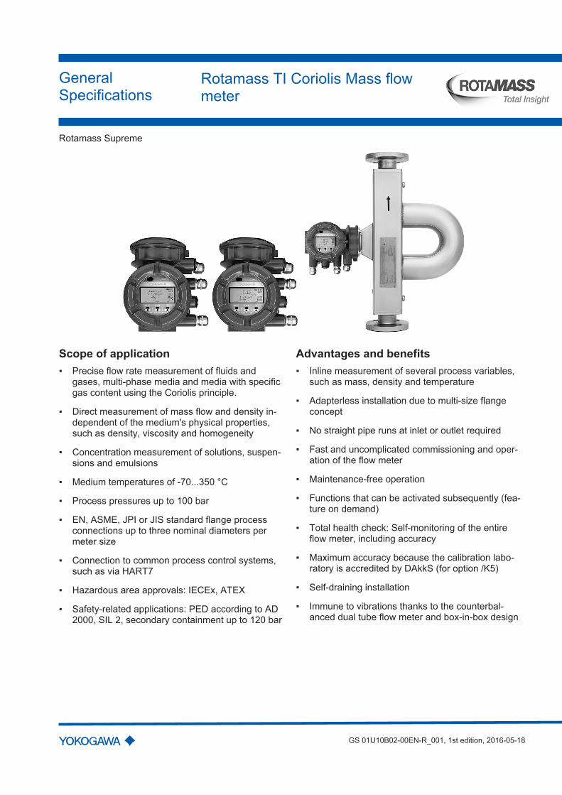
Scope of application Precise flow rate measurement of fluids and
gases, multi-phase media and media with specificgas content using the Coriolis principle.
Direct measurement of mass flow and density in-dependent of the medium's physical properties,such as density, viscosity and homogeneity
Concentration measurement of solutions, suspen-sions and emulsions
Medium temperatures of -70...350 °C
Process pressures up to 100 bar
EN, ASME, JPI or JIS standard flange processconnections up to three nominal diameters permeter size
Connection to common process control systems,such as via HART7
Hazardous area approvals: IECEx, ATEX
Safety-related applications: PED according to AD2000, SIL 2, secondary containment up to 120 bar
Advantages and benefits Inline measurement of several process variables,
such as mass, density and temperature
Adapterless installation due to multi-size flangeconcept
No straight pipe runs at inlet or outlet required
Fast and uncomplicated commissioning and oper-ation of the flow meter
Maintenance-free operation
Functions that can be activated subsequently (fea-ture on demand)
Total health check: Self-monitoring of the entireflow meter, including accuracy
Maximum accuracy because the calibration labo-ratory is accredited by DAkkS (for option /K5)
Self-draining installation
Immune to vibrations thanks to the counterbal-anced dual tube flow meter and box-in-box design
Rotamass Supreme
Table of contents
2 / 78 GS 01U10B02-00EN-R_001, 1st edition, 2016-05-18
Table of contents1 Introduction..................................................................................................................................................... 4
1.1 Applicable documents............................................................................................................................... 41.2 Product overview ...................................................................................................................................... 5
2 Measuring principle and flow meter ............................................................................................................. 62.1 Measuring principle................................................................................................................................... 62.2 Flow meter ................................................................................................................................................ 8
3 Application and measuring ranges............................................................................................................. 113.1 Measured quantity .................................................................................................................................. 113.2 Measuring range overview...................................................................................................................... 113.3 Mass flow................................................................................................................................................ 123.4 Volume flow ............................................................................................................................................ 123.5 Pressure loss .......................................................................................................................................... 123.6 Density.................................................................................................................................................... 133.7 Temperature ........................................................................................................................................... 13
4 Accuracy ....................................................................................................................................................... 144.1 Overview................................................................................................................................................. 144.2 Zero point stability of the mass flow........................................................................................................ 154.3 Mass flow accuracy ................................................................................................................................ 15
4.3.1 Sample calculation for liquids ................................................................................................. 164.3.2 Sample calculation for gases .................................................................................................. 17
4.4 Accuracy of density................................................................................................................................. 184.4.1 For liquids ............................................................................................................................... 184.4.2 For gases ................................................................................................................................ 18
4.5 Accuracy of mass flow and density according to MS code..................................................................... 194.5.1 For liquids ............................................................................................................................... 194.5.2 For gases ................................................................................................................................ 19
4.6 Volume flow accuracy............................................................................................................................. 204.6.1 For liquids ............................................................................................................................... 204.6.2 For gases ................................................................................................................................ 20
4.7 Accuracy of temperature......................................................................................................................... 214.8 Repeatability ........................................................................................................................................... 224.9 Calibration conditions ............................................................................................................................. 22
4.9.1 Mass flow calibration and density adjustment......................................................................... 224.9.2 Density calibration................................................................................................................... 23
5 Operating conditions ................................................................................................................................... 245.1 Location and position of installation........................................................................................................ 24
5.1.1 Sensor installation position ..................................................................................................... 245.2 Installation instructions ........................................................................................................................... 255.3 Process conditions.................................................................................................................................. 25
5.3.1 Medium temperature range..................................................................................................... 255.3.2 Density .................................................................................................................................... 265.3.3 Pressure.................................................................................................................................. 265.3.4 Mass flow ................................................................................................................................ 285.3.5 Effect of temperature on accuracy .......................................................................................... 28
Table of contents
GS 01U10B02-00EN-R_001, 1st edition, 2016-05-18 3 / 78
5.3.6 Insulation and heat tracing...................................................................................................... 295.4 Ambient conditions ................................................................................................................................. 30
5.4.1 Allowed ambient temperature for sensor ................................................................................ 315.4.2 Temperature specification by temperature classes ................................................................ 32
6 Mechanical specification ............................................................................................................................. 366.1 Design..................................................................................................................................................... 366.2 Material ................................................................................................................................................... 37
6.2.1 Material wetted parts............................................................................................................... 376.2.2 Non-wetted parts..................................................................................................................... 37
6.3 Process connections, dimensions and weights of sensor ...................................................................... 386.3.1 Process connections and overall length L1 ............................................................................ 39
6.4 Transmitter dimensions .......................................................................................................................... 51
7 Transmitter specification............................................................................................................................. 537.1 Inputs and outputs .................................................................................................................................. 54
7.1.1 Output signals ......................................................................................................................... 557.1.2 Input signals............................................................................................................................ 61
7.2 Power supply .......................................................................................................................................... 627.3 Cable specification.................................................................................................................................. 62
8 Approvals and declarations of conformity ................................................................................................ 63
9 Ordering information.................................................................................................................................... 649.1 MS code.................................................................................................................................................. 64
9.1.1 Transmitter .............................................................................................................................. 649.1.2 Sensor..................................................................................................................................... 649.1.3 Meter size ............................................................................................................................... 659.1.4 Material wetted parts............................................................................................................... 659.1.5 Process connection size ......................................................................................................... 659.1.6 Process connection type......................................................................................................... 669.1.7 Sensor housing material ......................................................................................................... 669.1.8 Medium temperature range..................................................................................................... 679.1.9 Mass flow and density accuracy ............................................................................................. 679.1.10 Design and housing ................................................................................................................ 689.1.11 Ex approval ............................................................................................................................. 689.1.12 Cable entries........................................................................................................................... 699.1.13 Inputs and outputs .................................................................................................................. 699.1.14 Display .................................................................................................................................... 70
9.2 Options ................................................................................................................................................... 719.2.1 Connecting cable length ......................................................................................................... 719.2.2 Additional nameplate information............................................................................................ 719.2.3 Presetting of customer parameters......................................................................................... 729.2.4 Concentration measurement................................................................................................... 729.2.5 Insulation and heat tracing...................................................................................................... 749.2.6 Certificates .............................................................................................................................. 749.2.7 Rupture disc............................................................................................................................ 769.2.8 Tube health check................................................................................................................... 769.2.9 Transmitter housing rotated 180°............................................................................................ 779.2.10 Measurement of heat quantity ................................................................................................ 779.2.11 Customer specific special product manufacture ..................................................................... 77

Rotamass SupremeIntroduction Applicable documents
4 / 78 GS 01U10B02-00EN-R_001, 1st edition, 2016-05-18
1 Introduction
1.1 Applicable documents
The following documents supplement these General Specifications: Ex instruction manual ATEX IM 01U10X01-00-R Ex instruction manual IECEx IM 01U10X02-00-R
Product overview
Rotamass SupremeIntroduction
GS 01U10B02-00EN-R_001, 1st edition, 1st edition, 2016-05-18 5 / 78
1.2 Product overview
Rotamass Coriolis flow meters are available in various product families distinguished bytheir applications. Each product family includes several product alternatives and addi-tional device options that can be selected.
The following overview serves as a guide for selecting products.Overview ofRotamass productfamilies
Rotamass Nano
For low flow rate applicationsFive meter sizes Nano 06, Nano 08, Nano 10, Nano 15,Nano 20 with the following connection sizes:
DN15, DN25, DN40 1/4", 1/2", 3/8", 3/4", 1", 1 1/2"
Maximum mass flow up to 1.5 t/h
Rotamass Prime
Versatility with low costs for the operatorFour meter sizes Prime 25, Prime 40, Prime 50, Prime 80with the following connection sizes:
DN15, DN25, DN40, DN50, DN80 3/8", 1/2", 3/4", 1", 1 1/2", 2", 2 1/2", 3"
Maximum mass flow up to 76 t/h
Rotamass Supreme
Excellent performance under demanding conditionsFour meter sizes Supreme 34, Supreme 36, Supreme 38,Supreme 39 with the following connection sizes:
DN15, DN25, DN40, DN50, DN80, DN100, DN125 3/8", 1/2", 3/4", 1", 1 1/2", 2", 2 1/2", 3", 4", 5"
Maximum mass flow up to 170 t/h
Rotamass Intense
For high process pressure applicationsThree meter sizes Intense 34, Intense 36, Intense 38 withthe following connection sizes:
1/2", 1", 2"Maximum mass flow up to 50 t/h
Rotamass Hygienic
For food, beverage and pharmaceutical applicationsFour meter sizes Hygienic 25, Hygienic 40, Hygienic 50,Hygienic 80 with the following connection sizes:
DN25, DN40, DN50, DN65, DN80 1", 1 1/2", 2", 2 1/2", 3"
Maximum mass flow up to 76 t/h
Rotamass Giga
For high flow rate applicationsTwo meter sizes Giga 1F, Giga 2H with the followingconnection sizes:
DN100, DN125, DN150, DN200 4", 5", 6", 8"
Maximum mass flow up to 600 t/h
Rotamass SupremeMeasuring principle and flow meter Measuring principle
6 / 78 GS 01U10B02-00EN-R_001, 1st edition, 2016-05-18
2 Measuring principle and flow meter
2.1 Measuring principle
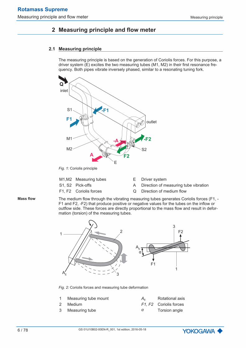
The measuring principle is based on the generation of Coriolis forces. For this purpose, adriver system (E) excites the two measuring tubes (M1, M2) in their first resonance fre-quency. Both pipes vibrate inversely phased, similar to a resonating tuning fork.
A
E
F1
S1
S2
F2
M1
Q
M2
-F1
-F2-A
inlet
outlet
Fig. 1: Coriolis principle
M1,M2 Measuring tubes E Driver systemS1, S2 Pick-offs A Direction of measuring tube vibrationF1, F2 Coriolis forces Q Direction of medium flow
Mass flow The medium flow through the vibrating measuring tubes generates Coriolis forces (F1, -F1 and F2, -F2) that produce positive or negative values for the tubes on the inflow oroutflow side. These forces are directly proportional to the mass flow and result in defor-mation (torsion) of the measuring tubes.
1
3
1
2
3AE
AE
F1
F2
α
Fig. 2: Coriolis forces and measuring tube deformation
1 Measuring tube mount AE Rotational axis2 Medium F1, F2 Coriolis forces3 Measuring tube α Torsion angle

Measuring principle
Rotamass SupremeMeasuring principle and flow meter
GS 01U10B02-00EN-R_001, 1st edition, 1st edition, 2016-05-18 7 / 78
The small deformation overlying the fundamental vibration is recorded by means of pick-offs (S1, S2) attached at suitable measuring tube locations. The resulting phase shift Δφbetween the output signals of pick-offs S1 and S2 is proportional to the mass flow. Theoutput signals generated are further processed in a transmitter.
Δφ
S1
S2
y
t
Fig. 3: Phase shift between output signals of S1 and S2 pick-offs
Δφ ~ FC ~
dt
dm
Δφ Phase shiftm Dynamic masst Timedm/dt Mass flow
Densitymeasurement
Using a driver and an electronic regulator, the measuring tubes are operated in their res-onance frequency ƒ. This resonance frequency is a function of measuring tube geometry,material properties and the mass of the medium covibrating in the measuring tubes. Alter-ing the density and the attendant mass will alter the resonance frequency. The transmittermeasures the resonance frequency and calculates density from it according to the for-mula below. Device-dependent constants are determined individually during calibration.
A
t
ƒ2
ƒ1
Fig. 4: Resonance frequency of measuring tubes
A Measuring tube displacementƒ1 Resonance frequency with medium 1ƒ2 Resonance frequency with medium 2
ρ = + ß ƒ2
α
ρ Medium densityƒ Resonance frequency of measuring tubesα, β Device-dependent constants
Temperaturemeasurement
The measuring tube temperature is measured in order to compensate for the effects oftemperature on the flow meter. This temperature approximately equals the medium tem-perature and is made available as a measured quantity at the transmitter as well.

Rotamass SupremeMeasuring principle and flow meter Flow meter
8 / 78 GS 01U10B02-00EN-R_001, 1st edition, 2016-05-18
2.2 Flow meter
The Rotamass Coriolis flow meter consists of: Sensor Transmitter
In the integral type, sensor and transmitter are firmly connected.
1
2
3
3
Fig. 5: Configuration of the Rotamass integral type
1 Transmitter2 Sensor3 Process connections
When the remote type is used, sensors and transmitters are linked via connecting cable.As a result, sensor and transmitter can be installed in different locations.
4 5
3
1
2
3
Fig. 6: Configuration of Rotamass remote type
1 Transmitter 4 Sensor terminal box2 Sensor 5 Connecting cable3 Process connections

Flow meter
Rotamass SupremeMeasuring principle and flow meter
GS 01U10B02-00EN-R_001, 1st edition, 1st edition, 2016-05-18 9 / 78
Generalspecifications
All available properties of the Rotamass Coriolis flow meter are specified by means of amodel code (MS code).
One MS code position may include several characters depicted by means of dashedlines.
The positions of the MS code relevant for the respective properties are depicted andhighlighted in blue. Any values that might occupy these MS code positions are subse-quently explained.
- - - - /-RC
1 2 3 4 6 75 9 10 11 12 13 14 158
Fig. 7: Highlighted MS code positions
U S 36 40H BA1 0 2 C5 A NN00 2 JA 1 P8- - - - /-RC
1 2 3 4 6 75 9 10 11 12 13 14 158
Fig. 8: Example of a completed MS code
A complete description of the MS code is included in the chapter entitled Ordering infor-mation [ 64].
Type of design Position 10 of the MS code defines whether the integral type or the remote type is used. Itspecifies further flow meter properties, such as the transmitter coating, see Design andhousing [ 68].
- - - - /-RC
1 2 3 4 6 75 9 10 11 12 13 14 158
Flow meter MS codePosition 10
Integral type
0, 2
Remote type
A, B, E, F
Rotamass SupremeMeasuring principle and flow meter Flow meter
10 / 78 GS 01U10B02-00EN-R_001, 1st edition, 2016-05-18
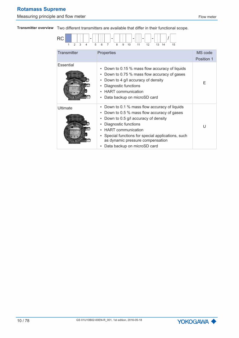
Transmitter overview Two different transmitters are available that differ in their functional scope.
- - - - /-RC
1 2 3 4 6 75 9 10 11 12 13 14 158
Transmitter Properties MS codePosition 1
Essential Down to 0.15 % mass flow accuracy of liquids Down to 0.75 % mass flow accuracy of gases Down to 4 g/l accuracy of density Diagnostic functions HART communication Data backup on microSD card
E
Ultimate Down to 0.1 % mass flow accuracy of liquids Down to 0.5 % mass flow accuracy of gases Down to 0.5 g/l accuracy of density Diagnostic functions HART communication Special functions for special applications, such
as dynamic pressure compensation Data backup on microSD card
U
Measured quantity
Rotamass SupremeApplication and measuring ranges
GS 01U10B02-00EN-R_001, 1st edition, 1st edition, 2016-05-18 11 / 78
3 Application and measuring ranges
3.1 Measured quantity
The Rotamass Coriolis flow meter can be used to measure the following media: Liquids Gases Mixtures, such as emulsions, suspensions, slurries
Possible limitations applying to measurement of mixtures must be checked with the re-sponsible Yokogawa sales organization.
The following variables can be measured using the Rotamass: Mass flow Density Temperature
Based on these measured quantities, the transmitter also calculates: Volume flow Partial component concentration of a two-component mixture Partial component flow rate of a mixture consisting of two components (net flow)
In this process, the net flow is calculated based on the known partial componentconcentration and the overall flow.
3.2 Measuring range overview
Supreme 34 Supreme 36 Supreme 38 Supreme 39Mass flow range
Typical connection size DN15/ ½" DN25/ 1" DN40/ 1½" DN80/ 3"
[ 12]Qnom 3 t/h 10 t/h 32 t/h 100 t/hQmax 5 t/h 17 t/h 50 t/h 170 t/h
Maximum volume flow(Water) 5 m3/h 17 m3/h 50 m3/h 170 m3/h [ 12]
Range of medium density0...5 kg/l [ 13]
Medium temperature rangeStandard1) -70...150 °C
[ 25]Mid-range -70...230 °CHigh 0...350 °C
1) May vary depending on the design.
Qnom - Nominal mass flow
Qmax - Maximum mass flow
The nominal mass flow Qnom is used as a characteristic for improved comparability.
Rotamass SupremeApplication and measuring ranges Mass flow
12 / 78 GS 01U10B02-00EN-R_001, 1st edition, 2016-05-18
3.3 Mass flow
The nominal mass flow Qnom is defined as the mass flow of water (temperature: 20 °C) at1 bar pressure loss along the flow meter.
For Rotamass Supreme the following meter sizes to be determined using the MS code[ 64] are available.
- - - - /-RC
1 2 3 4 6 75 9 10 11 12 13 14 158
S
Mass flow of liquids Sensor andmeter size
Typicalconnection size
Qnom
in t/hQmax
in t/hMS codePosition 3
Supreme 34 DN15/ ½" 3 5 34Supreme 36 DN25/ 1" 10 17 36Supreme 38 DN40/ 1½" 32 50 38Supreme 39 DN80/ 3" 100 170 39
Mass flow of gases When using the Rotamass for measuring the flow of gases, the mass flow is usually lim-ited by the pressure loss generated and the maximum flow velocity. Since these dependheavily on the application, it is strongly recommended that the Yokogawa FlowConfigura-tor software be used or the responsible Yokogawa sales organization be contacted whendesigning the size of the device.
3.4 Volume flow
Volume flow ofliquids (water at 20 °C)
Sensor andmeter size
Volume flow(at 1 bar pressure loss)
in m3/h
Maximum volume flowin m3/h
Supreme 34 3 5Supreme 36 10 17Supreme 38 32 50Supreme 39 100 170
Volume flow ofgases
When using the Rotamass for measuring the flow of gases, the flow rate is usually limitedby the pressure loss generated and the maximum flow velocity. Since these dependheavily on the application, it is strongly recommended that the Yokogawa FlowConfigura-tor software be used or the responsible Yokogawa sales organization be contacted whendesigning the size of the device.
3.5 Pressure loss
The pressure loss along the flow meter is heavily dependent on the application. The pres-sure loss of 1 bar at nominal mass flow Qnom also applies to water and is considered thereference value. Use of the Yokogawa FlowConfigurator software is recommended forachieving an accurate design.

Density
Rotamass SupremeApplication and measuring ranges
GS 01U10B02-00EN-R_001, 1st edition, 1st edition, 2016-05-18 13 / 78
3.6 Density
Meter size Measuring range of densitySupreme 34
0...5 kg/lSupreme 36Supreme 38Supreme 39 0...2 kg/l
Rather than being measured directly, density of gas is usually calculated using its refer-ence density, process temperature and process pressure.
3.7 Temperature
The temperature measuring range is limited by the allowed process temperature, seeMedium temperature range [ 25].
Maximum measuring range: -70...350 °C
Rotamass SupremeAccuracy Overview
14 / 78 GS 01U10B02-00EN-R_001, 1st edition, 2016-05-18
4 Accuracy
In this chapter, maximum deviations are indicated as amounts. The actual values maydeviate from the measured values by exceeding them or falling below.
4.1 Overview
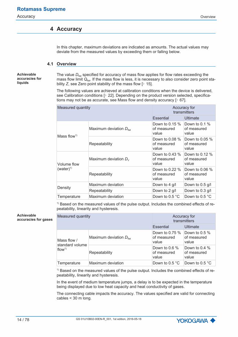
Achievableaccuracies forliquids
The value Dflat specified for accuracy of mass flow applies for flow rates exceeding themass flow limit Qflat. If the mass flow is less, it is necessary to also consider zero point sta-bility Z, see Zero point stability of the mass flow [ 15].
The following values are achieved at calibration conditions when the device is delivered,see Calibration conditions [ 22]. Depending on the product version selected, specifica-tions may not be as accurate, see Mass flow and density accuracy [ 67].
Measured quantity Accuracy fortransmitters
Essential Ultimate
Mass flow1)
Maximum deviation Dflat
Down to 0.15 %of measuredvalue
Down to 0.1 %of measuredvalue
RepeatabilityDown to 0.08 %of measuredvalue
Down to 0.05 %of measuredvalue
Volume flow(water)1)
Maximum deviation DV
Down to 0.43 %of measuredvalue
Down to 0.12 %of measuredvalue
RepeatabilityDown to 0.22 %of measuredvalue
Down to 0.06 %of measuredvalue
DensityMaximum deviation Down to 4 g/l Down to 0.5 g/lRepeatability Down to 2 g/l Down to 0.3 g/l
Temperature Maximum deviation Down to 0.5 °C Down to 0.5 °C1) Based on the measured values of the pulse output. Includes the combined effects of re-peatability, linearity and hysteresis.
Achievableaccuracies for gases
Measured quantity Accuracy fortransmitters
Essential Ultimate
Mass flow /standard volumeflow1)
Maximum deviation Dflat
Down to 0.75 %of measuredvalue
Down to 0.5 %of measuredvalue
RepeatabilityDown to 0.6 %of measuredvalue
Down to 0.4 %of measuredvalue
Temperature Maximum deviation Down to 0.5 °C Down to 0.5 °C1) Based on the measured values of the pulse output. Includes the combined effects of re-peatability, linearity and hysteresis.
In the event of medium temperature jumps, a delay is to be expected in the temperaturebeing displayed due to low heat capacity and heat conductivity of gases.
The connecting cable impacts the accuracy. The values specified are valid for connectingcables < 30 m long.
Zero point stability of the massflow
Rotamass SupremeAccuracy
GS 01U10B02-00EN-R_001, 1st edition, 1st edition, 2016-05-18 15 / 78
4.2 Zero point stability of the mass flow
The values Dflat specified for accuracy of mass flow apply for flow rates exceeding themass flow limit Qflat. If the mass flow is less, it is necessary to also consider zero point sta-bility Z (see chapter Mass flow accuracy [ 15]).
Meter size Zero point stability Zin kg/h
Supreme 34 0.15Supreme 36 0.5Supreme 38 1.6Supreme 39 5
4.3 Mass flow accuracy
Above mass flow Qflat, maximum deviation is constant and referred to as Dflat. It dependson the product version selected and can be found in the tables in chapter Accuracy ofmass flow and density according to MS code [ 19].
Taking zero point stability into consideration, the following calculation formulas are to beused for maximum deviation D:
D =
D =
Dflat
× 100 % Z × k
QQ < Q
flat
Z × k
Dflat
Q ≥ Qflat
= × 100 %
D Maximum deviation in % Qflat Mass flow above which Dflat appliesDflat Maximum deviation for high flow rates Z Zero point stabilityQ Mass flow in kg/h k Constant
Meter size kSupreme 34 2Supreme 36 2Supreme 38 2Supreme 39 2
Rotamass SupremeAccuracy Mass flow accuracy
16 / 78 GS 01U10B02-00EN-R_001, 1st edition, 2016-05-18
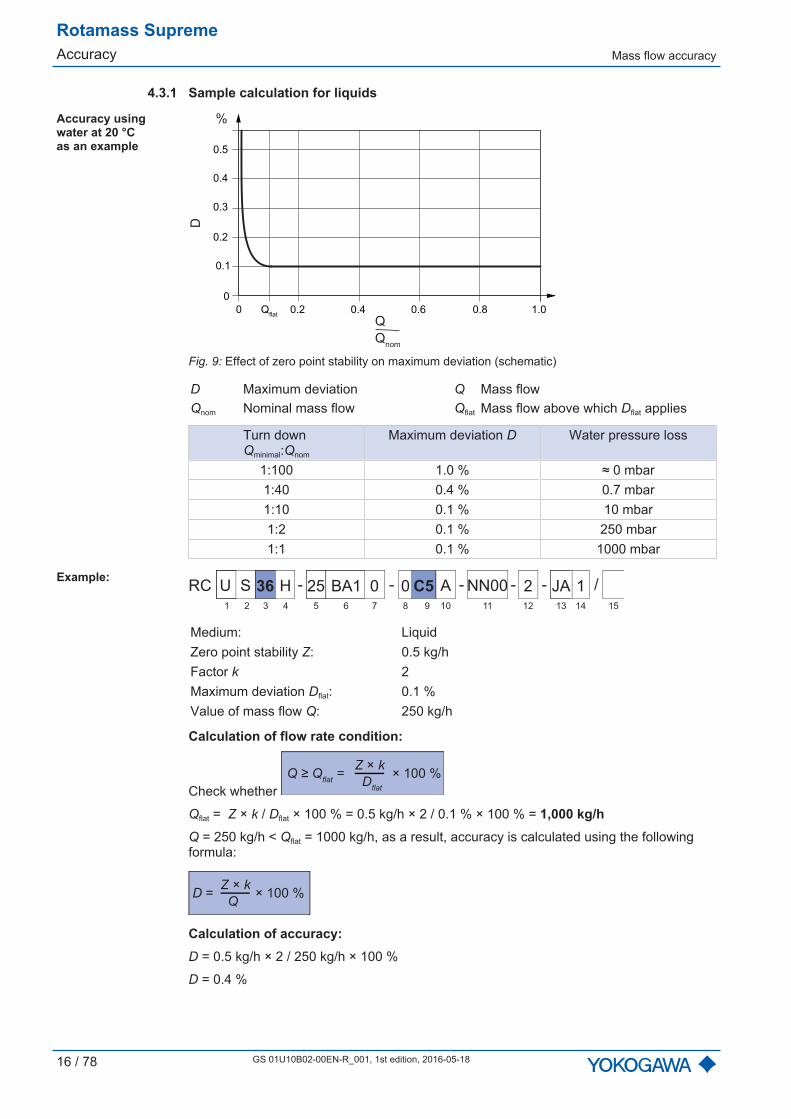
4.3.1 Sample calculation for liquids
Accuracy usingwater at 20 °C as an example
0
0.1
0.2
0.3
0.4
0 0.2 0.4 0.6 0.8 1.0
0.5
Qflat
Q
D
Qnom
%
Fig. 9: Effect of zero point stability on maximum deviation (schematic)
D Maximum deviation Q Mass flowQnom Nominal mass flow Qflat Mass flow above which Dflat applies
Turn down Qminimal:Qnom
Maximum deviation D Water pressure loss
1:100 1.0 % ≈ 0 mbar1:40 0.4 % 0.7 mbar1:10 0.1 % 10 mbar1:2 0.1 % 250 mbar1:1 0.1 % 1000 mbar
Example:U S 36 25H BA1 0 0 C5 A NN00 2 JA 1 P8- - - - /-RC
1 2 3 4 6 75 9 10 11 12 13 14 158
Medium: LiquidZero point stability Z: 0.5 kg/hFactor k 2Maximum deviation Dflat: 0.1 %Value of mass flow Q: 250 kg/h
Calculation of flow rate condition:
Check whether
Z × k
Dflat
Q ≥ Qflat
= × 100 %
Qflat = Z × k / Dflat × 100 % = 0.5 kg/h × 2 / 0.1 % × 100 % = 1,000 kg/hQ = 250 kg/h < Qflat = 1000 kg/h, as a result, accuracy is calculated using the followingformula:
D = × 100 % Z × k
Q
Calculation of accuracy:D = 0.5 kg/h × 2 / 250 kg/h × 100 %
D = 0.4 %
Mass flow accuracy
Rotamass SupremeAccuracy
GS 01U10B02-00EN-R_001, 1st edition, 1st edition, 2016-05-18 17 / 78
4.3.2 Sample calculation for gasesThe maximum deviation in the case of gases depends on the product version selected,see also Mass flow and density accuracy [ 67].
Example:U S 36 25H BA1 0 0 50 A NN00 2 JA 1 P8- - - - /-RC
1 2 3 4 6 75 9 10 11 12 13 14 158
Medium: GasZero point stability Z: 0.5 kg/hFactor k 2Maximum deviation Dflat: 0.5 %Value of mass flow Q: 100 kg/h
Calculation of flow rate condition:
Check whether
Z × k
Dflat
Q ≥ Qflat
= × 100 %
Qflat = Z × k / Dflat × 100 % = 0.5 kg/h × 2 / 0.5 % × 100 % = 200 kg/h
Q = 100 kg/h < Qflat = 200 kg/h, as a result, accuracy is calculated using the following for-mula:
D = × 100 % Z × k
Q
Calculation of accuracy:D = 0.5 kg/h × 2 / 100 kg/h × 100 %
D = 1.0 %
Since the mass flow of gas measurements is low, use of the Yokogawa FlowConfiguratorsoftware is recommended for designing the suitable product and contacting the responsi-ble Yokogawa sales office for this purpose.
Rotamass SupremeAccuracy Accuracy of density
18 / 78 GS 01U10B02-00EN-R_001, 1st edition, 2016-05-18
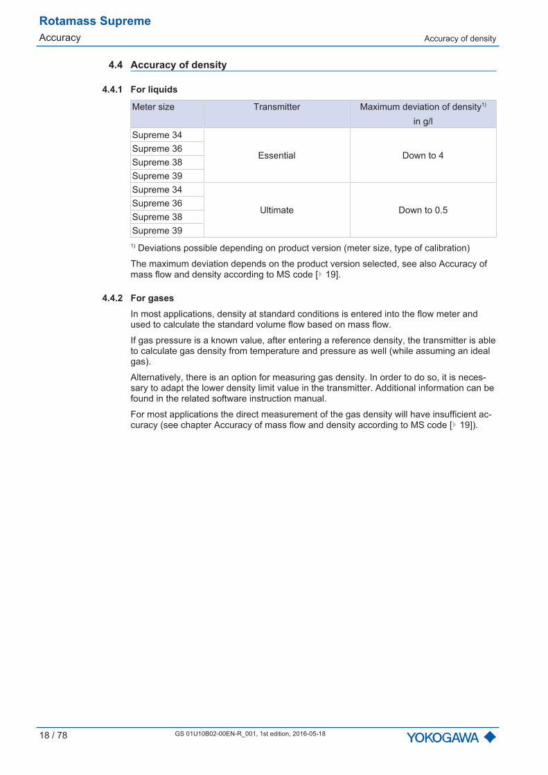
4.4 Accuracy of density
4.4.1 For liquids
Meter size Transmitter Maximum deviation of density1)
in g/lSupreme 34
Essential Down to 4Supreme 36Supreme 38Supreme 39Supreme 34
Ultimate Down to 0.5Supreme 36Supreme 38Supreme 39
1) Deviations possible depending on product version (meter size, type of calibration)
The maximum deviation depends on the product version selected, see also Accuracy ofmass flow and density according to MS code [ 19].
4.4.2 For gasesIn most applications, density at standard conditions is entered into the flow meter andused to calculate the standard volume flow based on mass flow.
If gas pressure is a known value, after entering a reference density, the transmitter is ableto calculate gas density from temperature and pressure as well (while assuming an idealgas).
Alternatively, there is an option for measuring gas density. In order to do so, it is neces-sary to adapt the lower density limit value in the transmitter. Additional information can befound in the related software instruction manual.
For most applications the direct measurement of the gas density will have insufficient ac-curacy (see chapter Accuracy of mass flow and density according to MS code [ 19]).
Accuracy of mass flow and densityaccording to MS code
Rotamass SupremeAccuracy
GS 01U10B02-00EN-R_001, 1st edition, 1st edition, 2016-05-18 19 / 78
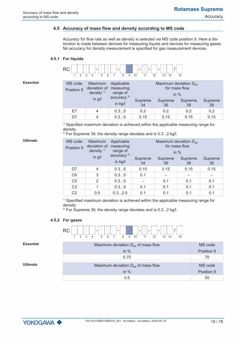
4.5 Accuracy of mass flow and density according to MS code
Accuracy for flow rate as well as density is selected via MS code position 9. Here a dis-tinction is made between devices for measuring liquids and devices for measuring gases.No accuracy for density measurement is specified for gas measurement devices.
4.5.1 For liquids
- - - - /-RC
1 2 3 4 6 75 9 10 11 12 13 14 158
Essential MS codePosition 9
Maximumdeviation of
density 1)
in g/l
Applicablemeasuringrange of
accuracy 2)
in kg/l
Maximum deviation Dflat for mass flow
in %Supreme
34Supreme
36Supreme
38Supreme
39E7 4 0.3...5 0.2 0.2 0.2 0.2D7 4 0.3...5 0.15 0.15 0.15 0.15
1) Specified maximum deviation is achieved within the applicable measuring range fordensity.2) For Supreme 39, the density range deviates and is 0.3...2 kg/l.
Ultimate MS codePosition 9
Maximumdeviation of
density 1)
in g/l
Applicablemeasuringrange of
accuracy 2)
in kg/l
Maximum deviation Dflat for mass flow
in %Supreme
34Supreme
36Supreme
38Supreme
39D7 4 0.3...5 0.15 0.15 0.15 0.15C6 3 0.3...5 0.1 – – –C5 2 0.3...5 – 0.1 0.1 0.1C3 1 0.3...5 0.1 0.1 0.1 0.1C2 0.5 0.3...2.5 0.1 0.1 0.1 0.1
1) Specified maximum deviation is achieved within the applicable measuring range fordensity.2) For Supreme 39, the density range deviates and is 0.3...2 kg/l.
4.5.2 For gases
- - - - /-RC
1 2 3 4 6 75 9 10 11 12 13 14 158
Essential Maximum deviation Dflat of mass flowin %
MS codePosition 9
0.75 70
Ultimate Maximum deviation Dflat of mass flowin %
MS codePosition 9
0.5 50
Rotamass SupremeAccuracy Volume flow accuracy
20 / 78 GS 01U10B02-00EN-R_001, 1st edition, 2016-05-18
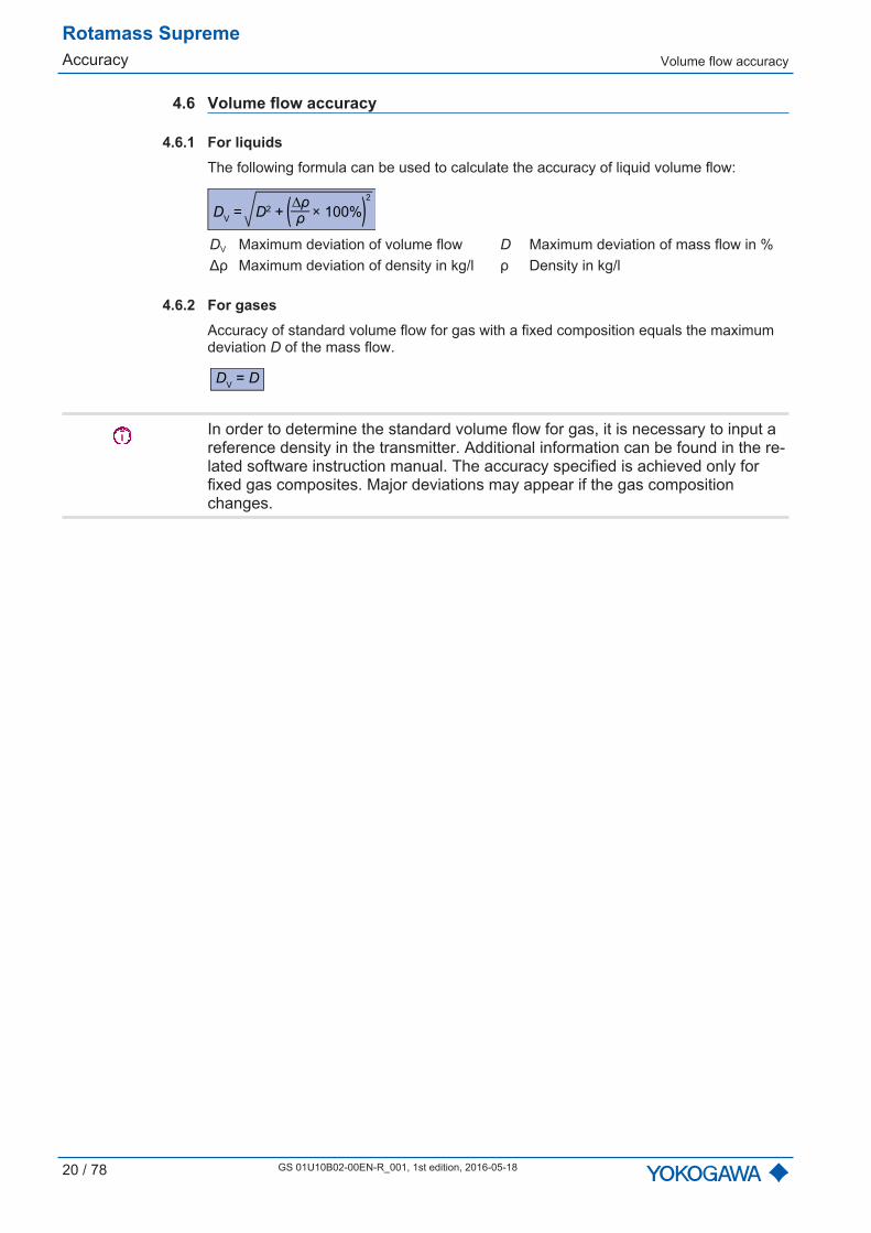
4.6 Volume flow accuracy
4.6.1 For liquidsThe following formula can be used to calculate the accuracy of liquid volume flow:
DV = D2 + × 100%
∆ρρ( )
2
DV Maximum deviation of volume flow D Maximum deviation of mass flow in %Δρ Maximum deviation of density in kg/l ρ Density in kg/l
4.6.2 For gasesAccuracy of standard volume flow for gas with a fixed composition equals the maximumdeviation D of the mass flow.
DV = D
In order to determine the standard volume flow for gas, it is necessary to input areference density in the transmitter. Additional information can be found in the re-lated software instruction manual. The accuracy specified is achieved only forfixed gas composites. Major deviations may appear if the gas compositionchanges.

Accuracy of temperature
Rotamass SupremeAccuracy
GS 01U10B02-00EN-R_001, 1st edition, 1st edition, 2016-05-18 21 / 78
4.7 Accuracy of temperature
Various medium temperature ranges are specified for Rotamass Supreme: Standard:
– Integral type: -50...150 °C– Remote type: -70...150 °C
Mid-range:– Remote type: -70...230 °C
High:– Remote type: 0...350 °C
Accuracy of temperature depends on the sensor temperature range selected (seeMedium temperature range [ 25]) and can be calculated as follows:
Formula fortemperaturespecificationsStandard and Mid-range
ΔT = 0.5 °C + 0.005 × |T - 20 °C|
ΔT Maximum deviation of temperatureT Temperature of medium
Formula fortemperaturespecification High
ΔT = 1.0 °C + 0.008 × |T - 20 °C|
ΔT Maximum deviation of temperatureT Temperature of medium
∆T
°C
0
0.5
1.0
1.5
2.0
-100 0 100 200 300
2.5
T
3.0
3.5
°C
1
2
Fig. 10: Presentation of temperature accuracy
1 Temperature specification High2 Temperature specifications Standard and Mid-range

Rotamass SupremeAccuracy Repeatability
22 / 78 GS 01U10B02-00EN-R_001, 1st edition, 2016-05-18
Example:U S 36 40H BA1 0 2 C5 A NN00 2 JA 1 P8- - - - /-RC
1 2 3 4 6 75 9 10 11 12 13 14 158
The sample MS code specifies the mid-temperature range.
Temperature of medium T: 50 °C
Calculation of accuracy:ΔT = 0.5 °C + 0.005 × |50 °C - 20 °C|
ΔT = 0.65 °C
4.8 Repeatability
When using default damping times, the specified repeatability of mass flow, density andtemperature measurements equals half of the respective maximum deviation.
R = 2
D
R RepeatabilityD Maximum deviation
In deviation hereto, the following applies to mass and standard volume flow of gases:
R = 1.25
D
4.9 Calibration conditions
4.9.1 Mass flow calibration and density adjustmentAll Rotamass are calibrated in accordance with the state of the art at Rota Yokogawa.Optionally, the calibration can be performed according to a method accredited by DAkkSin accordance with DIN EN ISO/IEC 17025:2005 (Option K5, see Certificates [ 75]).
Each Rotamass device comes with a standard calibration certificate.
Calibration takes place at reference conditions. Specific values are listed in the standardcalibration certificate.
Reference conditionsMedium WaterDensity 0.9...1.1 kg/l
Medium temperature10...35 °CAverage temperature: 22.5 °C
Ambient temperature 10...35 °CProcess pressure (absolute) 1...2 bar
The accuracy specified is achieved at as-delivered calibration conditions stated.
Calibration conditions
Rotamass SupremeAccuracy
GS 01U10B02-00EN-R_001, 1st edition, 1st edition, 2016-05-18 23 / 78
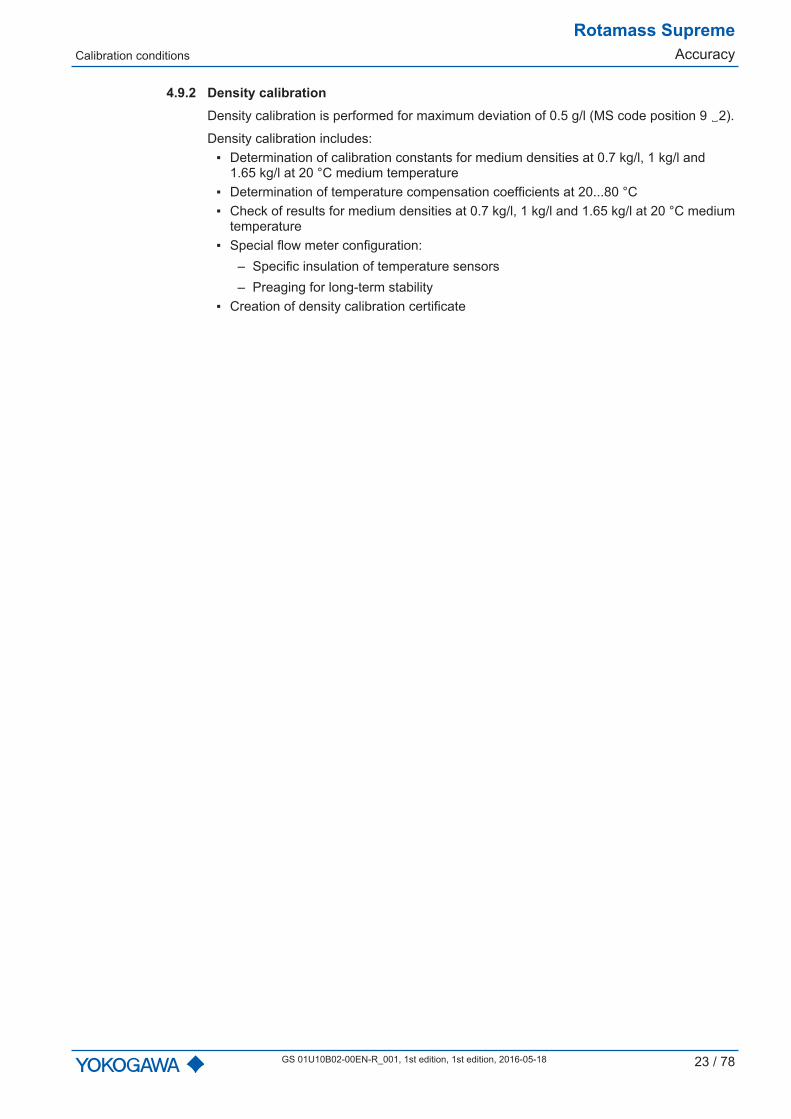
4.9.2 Density calibrationDensity calibration is performed for maximum deviation of 0.5 g/l (MS code position 9 2).
Density calibration includes: Determination of calibration constants for medium densities at 0.7 kg/l, 1 kg/l and
1.65 kg/l at 20 °C medium temperature Determination of temperature compensation coefficients at 20...80 °C Check of results for medium densities at 0.7 kg/l, 1 kg/l and 1.65 kg/l at 20 °C medium
temperature Special flow meter configuration:
– Specific insulation of temperature sensors– Preaging for long-term stability
Creation of density calibration certificate

Rotamass SupremeOperating conditions
Location and position of installa-tion
24 / 78 GS 01U10B02-00EN-R_001, 1st edition, 2016-05-18
5 Operating conditions
5.1 Location and position of installation
Rotamass Coriolis flow meters can be mounted horizontally, vertically and at an incline.The measuring tubes should be completely filled with the medium during this process asaccumulations of air or formation of gas bubbles in the measuring tube may result in er-rors in measurement. Straight pipe runs at inlet or outlet are usually not required.
Avoid the following installation locations and positions: Measuring tubes as highest point in piping when measuring liquids Measuring tubes as lowest point in piping when measuring gases Immediately in front of a free pipe outlet in a downpipe Lateral positions
Fig. 11: Installation position to be avoided: Flow meter in sideways position
5.1.1 Sensor installation positionSensor installationposition as afunction of themedium
Installation position Medium DescriptionHorizontal, measuring tubes atbottom
LiquidThe measuring tubes are orientedtoward the bottom. Accumulation ofgas bubbles is avoided.
Horizontal, measuring tubes at top
GasThe measuring tubes are orientedtoward the top. Accumulation of liquid,such as condensate is avoided.

Installation instructions
Rotamass SupremeOperating conditions
GS 01U10B02-00EN-R_001, 1st edition, 1st edition, 2016-05-18 25 / 78
Installation position Medium DescriptionVertical, direction of flow towardsthe top
Liquid/gas
The sensor is installed on a pipe withthe direction of flow towards the top.Accumulation of gas bubbles or solidsis avoided. This position allows forcomplete self-draining of the measuringtubes.
5.2 Installation instructions
The following instructions for installation must be observed:1. Protect the flow meter from direct sun irradiation in order to avoid exceeding the maxi-
mum allowed internal temperature of the transmitter.2. In case of installing two sensors of the same kind back-to-back redundantly, use a
customized design and contact the responsible Yokogawa sales organization.3. Avoid installation locations susceptible to cavitation, such as immediately behind a
control valve.4. In case that the medium temperatures deviate approx. 80 °C from the ambient tem-
perature, insulating the sensor is recommended if the goal is to maintain utmost accu-racy, see Insulation and heat tracing [ 29].
5. Avoid installation directly behind rotary and gear pumps to prevent fluctuations inpressure from interfering with the resonance frequency of the Rotamass measuringtubes.
5.3 Process conditions
5.3.1 Medium temperature range
The Rotamass specification for use in Ex areas is different, see Ex instructionmanual (IM 01U10X-00EN).
For Rotamass Supreme the following medium temperature ranges are available:
- - - - /-RC
1 2 3 4 6 75 9 10 11 12 13 14 158
Temperaturespecification
MS codePosition 8
Mediumtemperature
in °C
Design MS codePosition 10
Standard 0-50...150 Integral type 0, 2-70...150 Remote type A, B, E, F
Mid-range 2 -70...230 Remote type B, FHigh 3 0...350 Remote type B, F
Rotamass SupremeOperating conditions Process conditions
26 / 78 GS 01U10B02-00EN-R_001, 1st edition, 2016-05-18
5.3.2 Density
Meter size Measuring range of densitySupreme 34
0...5 kg/lSupreme 36Supreme 38Supreme 39 0...2 kg/l
Rather than being measured directly, density of gas is usually calculated using its refer-ence density, process temperature and process pressure.
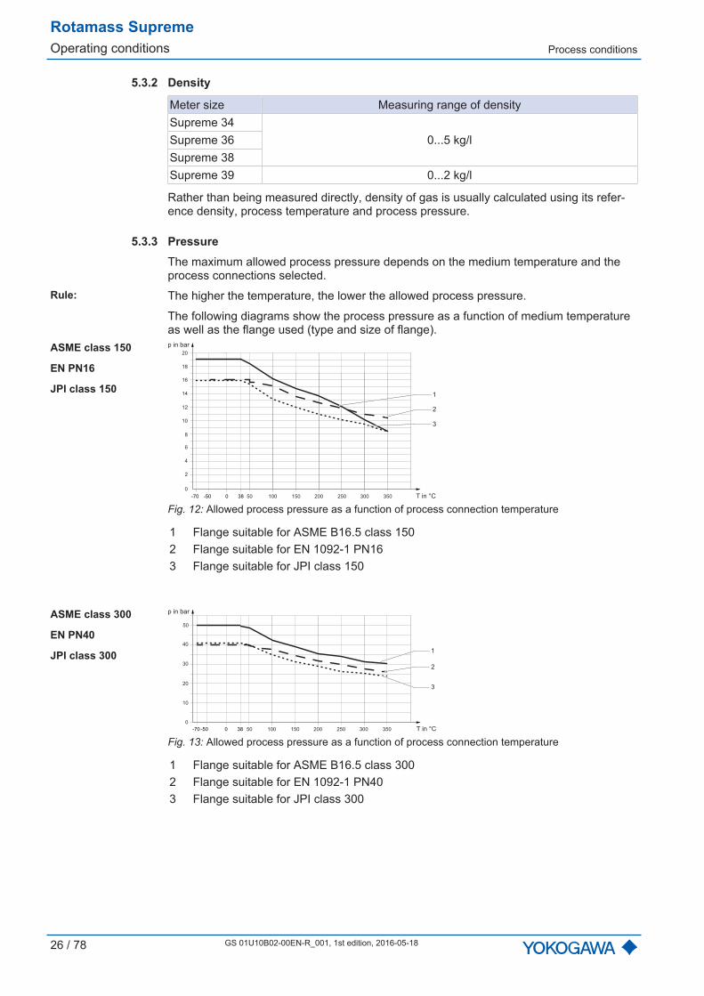
5.3.3 PressureThe maximum allowed process pressure depends on the medium temperature and theprocess connections selected.
Rule: The higher the temperature, the lower the allowed process pressure.
The following diagrams show the process pressure as a function of medium temperatureas well as the flange used (type and size of flange).
ASME class 150
EN PN16
JPI class 1501
2
3
50
2
0
4
6
8
10
12
14
16
18
20
100 150 200 250 300 350
p in bar
T in °C-70 0 38-50
Fig. 12: Allowed process pressure as a function of process connection temperature
1 Flange suitable for ASME B16.5 class 1502 Flange suitable for EN 1092-1 PN163 Flange suitable for JPI class 150
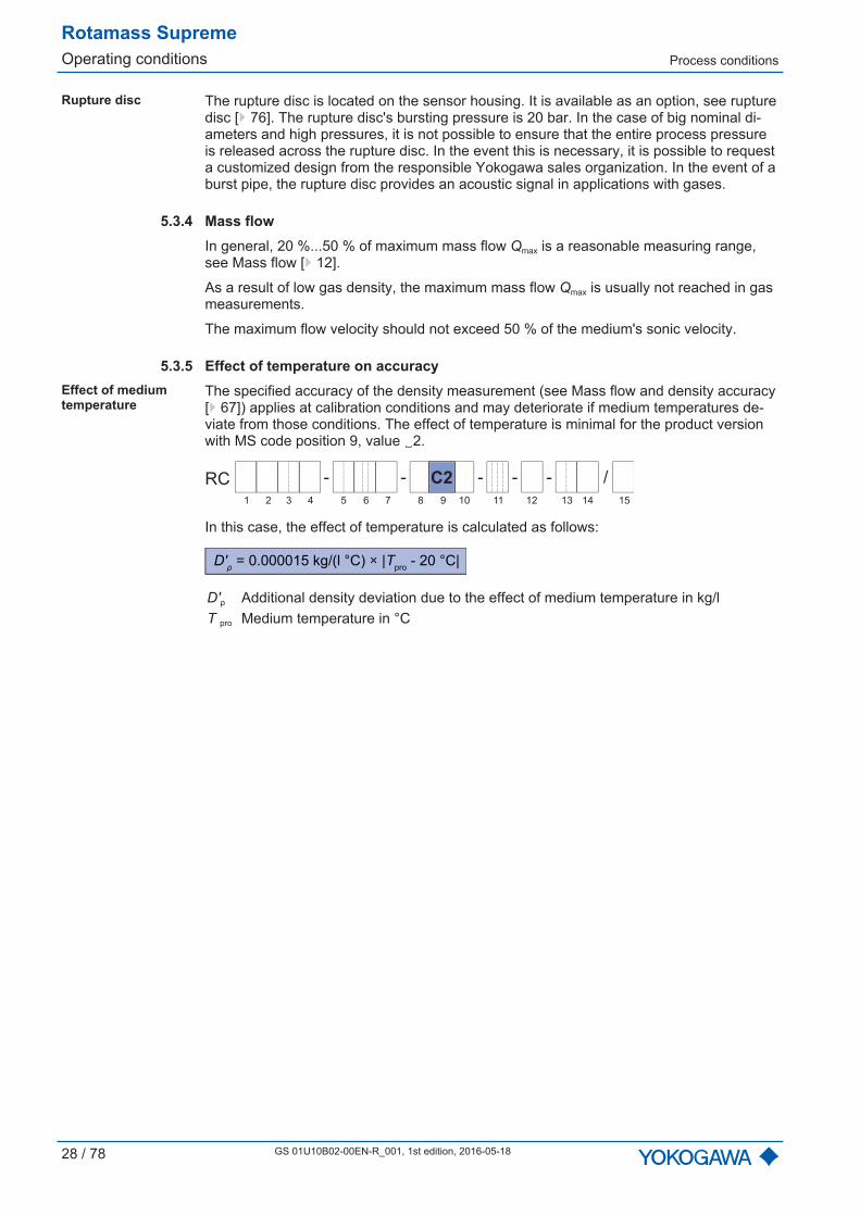
ASME class 300
EN PN40
JPI class 300 1
2
3
50
10
0
20
30
40
50
100 150 200 250 300 350 T in °C
p in bar
-70 0 38-50
Fig. 13: Allowed process pressure as a function of process connection temperature
1 Flange suitable for ASME B16.5 class 3002 Flange suitable for EN 1092-1 PN403 Flange suitable for JPI class 300

Process conditions
Rotamass SupremeOperating conditions
GS 01U10B02-00EN-R_001, 1st edition, 1st edition, 2016-05-18 27 / 78
ASME class 600
EN PN63
JPI class 600
50
20
0
40
60
80
100
100 150 200 250 300 350 T in °C
p in bar
-70 0 38-50
1
2
3
Fig. 14: Allowed process pressure as a function of process connection temperature
1 Flange suitable for ASME B16.5 class 6002 Flange suitable for JPI class 6003 Flange suitable for EN 1092-1 PN63
EN PN100
50
20
0
40
60
80
100
120
100 150 200 250 300 350 T in °C
p in bar
0-50-70
Fig. 15: Allowed process pressure as a function of process connection temperature, suitable forflange EN 1092-1 PN100
JIS 10K
-50 500
2
0
4
6
8
10
12
14
16
100 150 200 250 300 T in °C
p in bar
Fig. 16: Allowed process pressure as a function of process connection temperature, suitable forflange JIS B 2220 10K
Process connectionswith internal thread
-50 500
50
0
100
150
200
250
300
100 150 200 250 300 350 T in °C
p in bar
Fig. 17: Allowed process pressure as a function of temperature, suitable for process connectiontemperature, suitable for process connections with internal thread G and NPT
Rotamass SupremeOperating conditions Process conditions
28 / 78 GS 01U10B02-00EN-R_001, 1st edition, 2016-05-18
Rupture disc The rupture disc is located on the sensor housing. It is available as an option, see rupturedisc [ 76]. The rupture disc's bursting pressure is 20 bar. In the case of big nominal di-ameters and high pressures, it is not possible to ensure that the entire process pressureis released across the rupture disc. In the event this is necessary, it is possible to requesta customized design from the responsible Yokogawa sales organization. In the event of aburst pipe, the rupture disc provides an acoustic signal in applications with gases.
5.3.4 Mass flowIn general, 20 %...50 % of maximum mass flow Qmax is a reasonable measuring range,see Mass flow [ 12].
As a result of low gas density, the maximum mass flow Qmax is usually not reached in gasmeasurements.
The maximum flow velocity should not exceed 50 % of the medium's sonic velocity.
5.3.5 Effect of temperature on accuracyEffect of mediumtemperature
The specified accuracy of the density measurement (see Mass flow and density accuracy[ 67]) applies at calibration conditions and may deteriorate if medium temperatures de-viate from those conditions. The effect of temperature is minimal for the product versionwith MS code position 9, value 2.
- - - - /-RC
1 2 3 4 6 75 9 10 11 12 13 14 158
C2
In this case, the effect of temperature is calculated as follows:
D'ρ = 0.000015 kg/(l °C) × |T
pro - 20 °C|
D'ρ Additional density deviation due to the effect of medium temperature in kg/lT pro Medium temperature in °C
Process conditions
Rotamass SupremeOperating conditions
GS 01U10B02-00EN-R_001, 1st edition, 1st edition, 2016-05-18 29 / 78
5.3.6 Insulation and heat tracing
In case that the medium temperature deviates more than 80°C from the ambienttemperature, insulating the sensor is recommended to avoid negative effectsfrom temperature fluctuations on accuracy.
- - - - /-RC
1 2 3 4 6 75 9 10 11 12 13 14 158
Overview of deviceoptions forinsulation and heattracing for remotetype
Description Options Insulation T10 Insulation Heat tracing without ventilation
T21, T22, T26
Insulation Heat tracing with ventilation
T31, T32, T36
For details about the device options see chapter under the same heading Insulation andheat tracing [ 74] in the MS code description.
If the sensor is insulated subsequently, the following must be noted: Do not insulate transmitter as well. In case of remote type, do not insulate the terminal box of the sensor. Do not expose transmitters to ambient temperatures exceeding 60 °C. The preferred insulation is 80 mm thick with a heat transfer coefficient of 0.4 W/m² K. The maximum temperature of the heat-carrying medium equals the maximum
medium temperature. The minimum temperature of the heat-carrying medium is 0 °C,a limit value the temperature must not fall below.
Electrical heating can be provided subsequently, such as in the form of heating tapes, aheating jacket or by way of hot water or steam running through copper pipes. When usingheat tracing, the sensor must be magnetically shielded in case its heat control is realizedby way of phase-angle control or pulse packets.
In hazardous areas, subsequent application of insulation, heating jacket or heat-ing strips is not permitted.

Rotamass SupremeOperating conditions Ambient conditions
30 / 78 GS 01U10B02-00EN-R_001, 1st edition, 2016-05-18
5.4 Ambient conditions
Rotamass can be used at demanding ambient conditions.
In doing so, the following specifications must be taken into account:
Ambient temperature Sensor: see [ 31] Transmitter: -40...60 °C Transmitter display has only limited legi-
bility below -20 °CStorage temperature Sensor: -50...80 °C
Transmitter: -40...60 °CRelative humidity 0...95 %IP code IP66/67 for transmitters and sensors when
using the appropriate cable glandsAllowable pollution degree in surroundingarea according to EN 61010-1
4 (in operation)
Resistance to vibration according to IEC60068-2-6 (without option T)
Transmitter: 10...500 Hz, 1 gSensor: 25...100 Hz, 4 g
Electromagnetic compatibility (EMC) ac-cording to IEC/EN 61326 as well as NA-MUR recommendation NE 21
Requirement during immunity tests: Theoutput signal fluctuation is specified withinthe ±1 % output span.
Maximum altitude 2000 m above mean sea level (MSL)Overvoltage category according to IEC/EN61010-1
II
Ambient conditions
Rotamass SupremeOperating conditions
GS 01U10B02-00EN-R_001, 1st edition, 1st edition, 2016-05-18 31 / 78
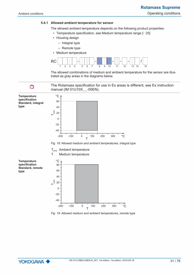
5.4.1 Allowed ambient temperature for sensorThe allowed ambient temperature depends on the following product properties:
Temperature specification, see Medium temperature range [ 25] Housing design
– Integral type– Remote type
Medium temperature
- - - - /-RC
1 2 3 4 6 75 9 10 11 12 13 14 158
The allowed combinations of medium and ambient temperature for the sensor are illus-trated as gray areas in the diagrams below.
The Rotamass specification for use in Ex areas is different, see Ex instructionmanual (IM 01U10X-00EN).
TemperaturespecificationStandard, integraltype
0
0 100-100-200
20
40
-40
-20
60
°C
°C
Tamb
T200 300
Fig. 18: Allowed medium and ambient temperatures, integral type
Tamb Ambient temperatureT Medium temperature
TemperaturespecificationStandard, remotetype
0
0 100-100-200
20
40
-40
-20
60
80
°C
°C
Tamb
T200 300
Fig. 19: Allowed medium and ambient temperatures, remote type
Rotamass SupremeOperating conditions Ambient conditions
32 / 78 GS 01U10B02-00EN-R_001, 1st edition, 2016-05-18
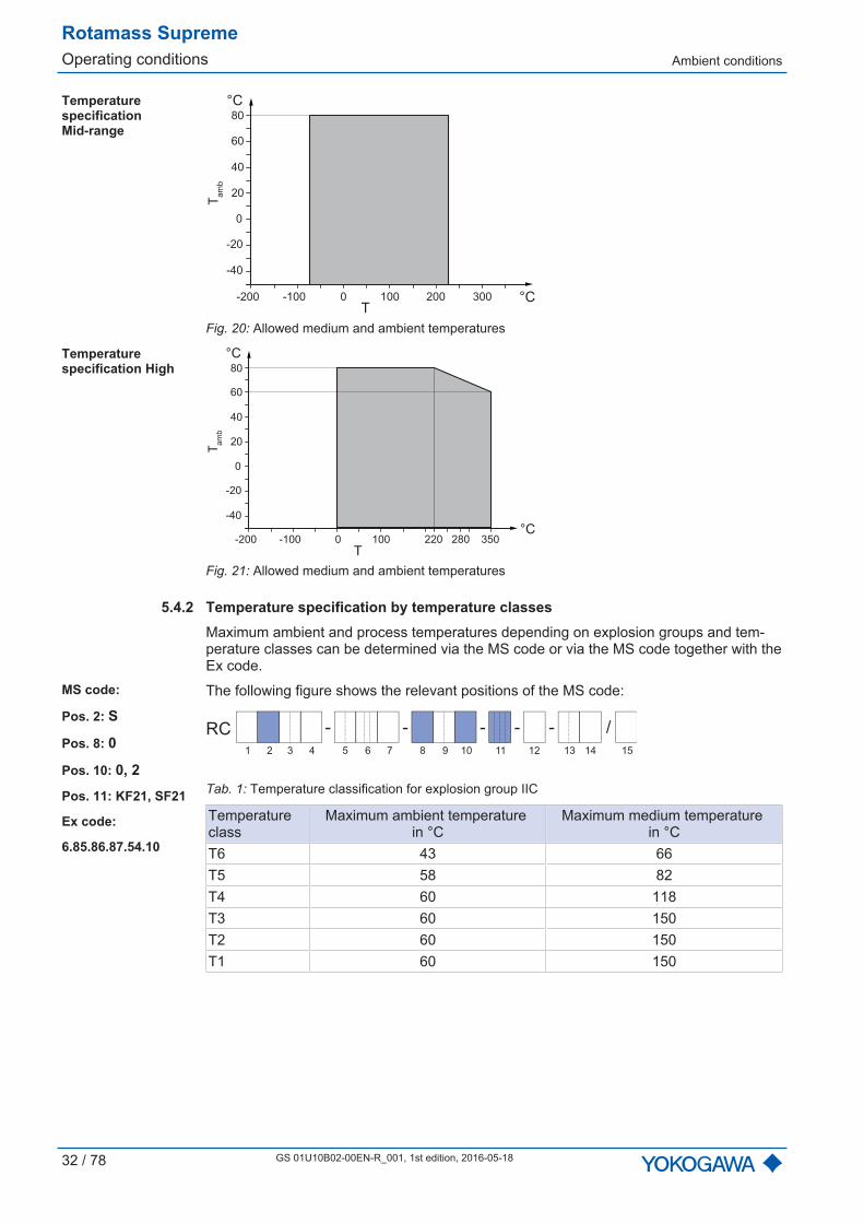
Temperaturespecification Mid-range
0
0 100-100-200
20
40
-40
-20
60
80
°C
°C
Tamb
T200 300
Fig. 20: Allowed medium and ambient temperatures
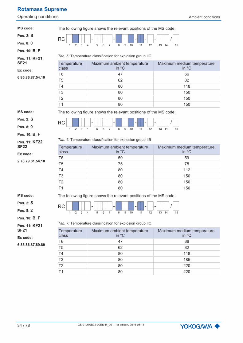
Temperaturespecification High
0
0 100-100-200
20
40
-40
-20
60
80
°C
°C
Tamb
T220 350280
Fig. 21: Allowed medium and ambient temperatures
5.4.2 Temperature specification by temperature classesMaximum ambient and process temperatures depending on explosion groups and tem-perature classes can be determined via the MS code or via the MS code together with theEx code.
MS code:
Pos. 2: S
Pos. 8: 0
Pos. 10: 0, 2
Pos. 11: KF21, SF21
Ex code:
6.85.86.87.54.10
The following figure shows the relevant positions of the MS code:
- - - - /-RC
1 2 3 4 6 75 9 10 11 12 13 14 158
Tab. 1: Temperature classification for explosion group IIC
Temperatureclass
Maximum ambient temperature in °C
Maximum medium temperature in °C
T6 43 66T5 58 82T4 60 118T3 60 150T2 60 150T1 60 150

Ambient conditions
Rotamass SupremeOperating conditions
GS 01U10B02-00EN-R_001, 1st edition, 1st edition, 2016-05-18 33 / 78
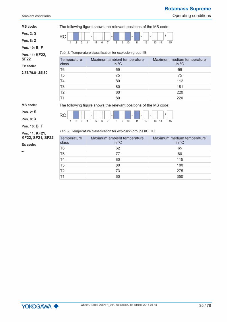
MS code:
Pos. 2: S
Pos. 8: 0
Pos. 10: 0, 2
Pos. 11: KF22,SF22
Ex code:
2.78.79.81.54.10
The following figure shows the relevant positions of the MS code:
- - - - /-RC
1 2 3 4 6 75 9 10 11 12 13 14 158
Tab. 2: Temperature classification for explosion group IIB
Temperatureclass
Maximum ambient temperature in °C
Maximum medium temperature in °C
T6 59 59T5 60 75T4 60 112T3 60 150T2 60 150T1 60 150
MS code:
Pos. 2: S
Pos. 8: 0
Pos. 10: A, E
Pos. 11: KF21,SF21
Ex code:
6.85.86.87.54.10
The following figure shows the relevant positions of the MS code:
- - - - /-RC
1 2 3 4 6 75 9 10 11 12 13 14 158
Tab. 3: Temperature classification for explosion group IIC
Temperatureclass
Maximum ambient temperature in °C
Maximum medium temperature in °C
T6 41 66T5 56 82T4 80 118T3 78 150T2 78 150T1 78 150
MS code:
Pos. 2: S
Pos. 8: 0
Pos. 10: A, E
Pos. 11: KF22,SF22
Ex code:
2.78.79.81.54.10
The following figure shows the relevant positions of the MS code:
- - - - /-RC
1 2 3 4 6 75 9 10 11 12 13 14 158
Tab. 4: Temperature classification for explosion group IIB
Temperatureclass
Maximum ambient temperature in °C
Maximum medium temperature in °C
T6 59 59T5 75 75T4 80 112T3 78 150T2 78 150T1 78 150
Rotamass SupremeOperating conditions Ambient conditions
34 / 78 GS 01U10B02-00EN-R_001, 1st edition, 2016-05-18
MS code:
Pos. 2: S
Pos. 8: 0
Pos. 10: B, F
Pos. 11: KF21,SF21
Ex code:
6.85.86.87.54.10
The following figure shows the relevant positions of the MS code:
- - - - /-RC
1 2 3 4 6 75 9 10 11 12 13 14 158
Tab. 5: Temperature classification for explosion group IIC
Temperatureclass
Maximum ambient temperature in °C
Maximum medium temperature in °C
T6 47 66T5 62 82T4 80 118T3 80 150T2 80 150T1 80 150
MS code:
Pos. 2: S
Pos. 8: 0
Pos. 10: B, F
Pos. 11: KF22,SF22
Ex code:
2.78.79.81.54.10
The following figure shows the relevant positions of the MS code:
- - - - /-RC
1 2 3 4 6 75 9 10 11 12 13 14 158
Tab. 6: Temperature classification for explosion group IIB
Temperatureclass
Maximum ambient temperature in °C
Maximum medium temperature in °C
T6 59 59T5 75 75T4 80 112T3 80 150T2 80 150T1 80 150
MS code:
Pos. 2: S
Pos. 8: 2
Pos. 10: B, F
Pos. 11: KF21,SF21
Ex code:
6.85.86.87.89.80
The following figure shows the relevant positions of the MS code:
- - - - /-RC
1 2 3 4 6 75 9 10 11 12 13 14 158
Tab. 7: Temperature classification for explosion group IIC
Temperatureclass
Maximum ambient temperature in °C
Maximum medium temperature in °C
T6 47 66T5 62 82T4 80 118T3 80 185T2 80 220T1 80 220
Ambient conditions
Rotamass SupremeOperating conditions
GS 01U10B02-00EN-R_001, 1st edition, 1st edition, 2016-05-18 35 / 78
MS code:
Pos. 2: S
Pos. 8: 2
Pos. 10: B, F
Pos. 11: KF22,SF22
Ex code:
2.78.79.81.85.80
The following figure shows the relevant positions of the MS code:
- - - - /-RC
1 2 3 4 6 75 9 10 11 12 13 14 158
Tab. 8: Temperature classification for explosion group IIB
Temperatureclass
Maximum ambient temperature in °C
Maximum medium temperature in °C
T6 59 59T5 75 75T4 80 112T3 80 181T2 80 220T1 80 220
MS code:
Pos. 2: S
Pos. 8: 3
Pos. 10: B, F
Pos. 11: KF21,KF22, SF21, SF22
Ex code:
–
The following figure shows the relevant positions of the MS code:
- - - - /-RC
1 2 3 4 6 75 9 10 11 12 13 14 158
Tab. 9: Temperature classification for explosion groups IIC, IIB
Temperatureclass
Maximum ambient temperature in °C
Maximum medium temperature in °C
T6 62 65T5 77 80T4 80 115T3 80 180T2 73 275T1 60 350
Rotamass SupremeMechanical specification Design
36 / 78 GS 01U10B02-00EN-R_001, 1st edition, 2016-05-18
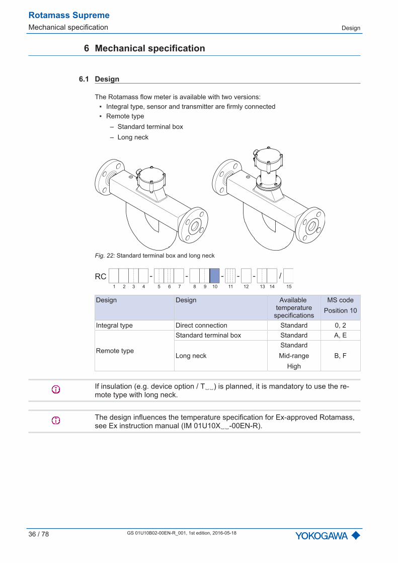
6 Mechanical specification
6.1 Design
The Rotamass flow meter is available with two versions: Integral type, sensor and transmitter are firmly connected Remote type
– Standard terminal box– Long neck
Fig. 22: Standard terminal box and long neck
- - - - /-RC
1 2 3 4 6 75 9 10 11 12 13 14 158
Design Design Available temperature
specifications
MS codePosition 10
Integral type Direct connection Standard 0, 2
Remote type
Standard terminal box Standard A, E
Long neckStandardMid-range
HighB, F
If insulation (e.g. device option / T) is planned, it is mandatory to use the re-mote type with long neck.
The design influences the temperature specification for Ex-approved Rotamass,see Ex instruction manual (IM 01U10X-00EN-R).
Material
Rotamass SupremeMechanical specification
GS 01U10B02-00EN-R_001, 1st edition, 1st edition, 2016-05-18 37 / 78
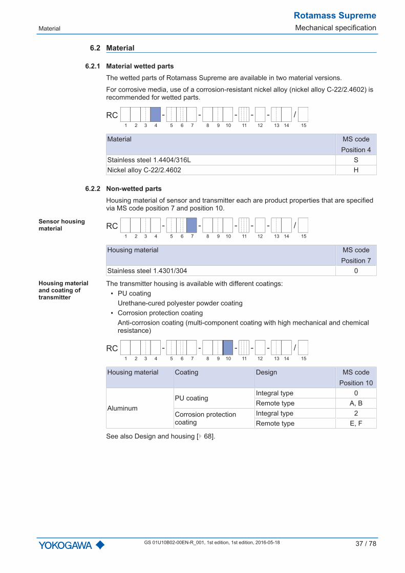
6.2 Material
6.2.1 Material wetted partsThe wetted parts of Rotamass Supreme are available in two material versions.
For corrosive media, use of a corrosion-resistant nickel alloy (nickel alloy C-22/2.4602) isrecommended for wetted parts.
- - - - /-RC
1 2 3 4 6 75 9 10 11 12 13 14 158
Material MS codePosition 4
Stainless steel 1.4404/316L SNickel alloy C-22/2.4602 H
6.2.2 Non-wetted partsHousing material of sensor and transmitter each are product properties that are specifiedvia MS code position 7 and position 10.
Sensor housingmaterial - - - - /-RC
1 2 3 4 6 75 9 10 11 12 13 14 158
Housing material MS codePosition 7
Stainless steel 1.4301/304 0
Housing materialand coating oftransmitter
The transmitter housing is available with different coatings: PU coating
Urethane-cured polyester powder coating Corrosion protection coating
Anti-corrosion coating (multi-component coating with high mechanical and chemicalresistance)
- - - - /-RC
1 2 3 4 6 75 9 10 11 12 13 14 158
Housing material Coating Design MS codePosition 10
AluminumPU coating
Integral type 0Remote type A, B
Corrosion protectioncoating
Integral type 2Remote type E, F
See also Design and housing [ 68].

Rotamass SupremeMechanical specification
Process connections, dimensionsand weights of sensor
38 / 78 GS 01U10B02-00EN-R_001, 1st edition, 2016-05-18
6.3 Process connections, dimensions and weights of sensor
L1 ±5
L2
L3 W1
H1
H5
ø 102
98
W2
H4
80
H6
ø 102
H7
H8
H9 H
6 D
1
D2
Ø 102
L5
L1
W3
L4
H3
Fig. 23: Dimensions in mm
Overall length L1 see Process connections and overall length L1 [ 39].
Sensor andmeter size
L2 L3 L4 L5 H1 H3 H4 H5 H6 H7 H8 H9 W1 W2 W3 D1 D2 Weight 1)
in mm in kgSupreme 34 272 212 420 310 177 279 80 138 218 411 273 138 60 80 240 200 330 9...18Supreme 36 400 266 540 439 230 279 80 138 218 464 326 138 76 90 260 250 380 15...25Supreme 38 490 267 640 530 269 289 100 148 228 524 376 148 89 110 260 250 430 25...42Supreme 39 850 379 1000 894 370 306 135 166 246 668 503 165 129 160 302 350 545 58...106
1) Information on sensor weight with smallest and largest process connections, without in-sulation or heating
The weight depends on the process connections.
Process connections, dimensionsand weights of sensor
Rotamass SupremeMechanical specification
GS 01U10B02-00EN-R_001, 1st edition, 1st edition, 2016-05-18 39 / 78
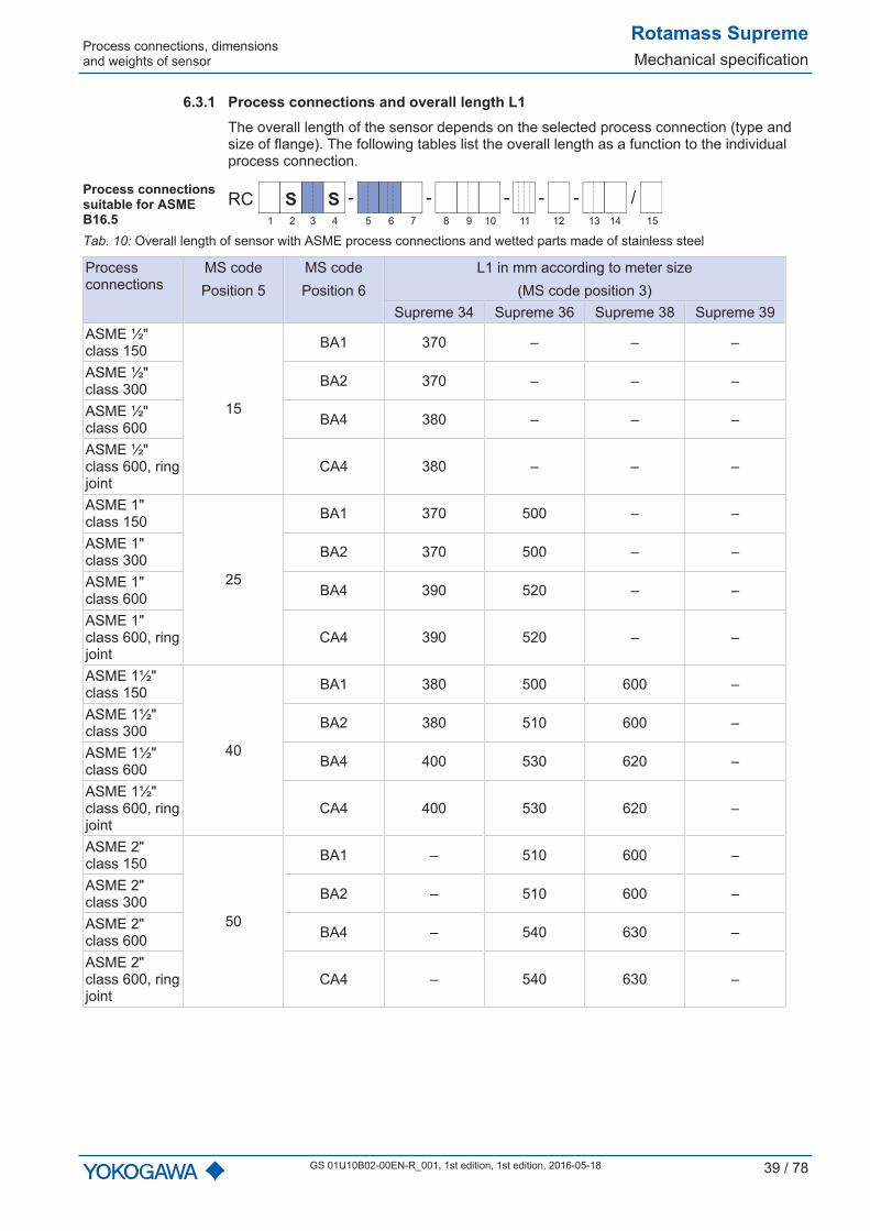
6.3.1 Process connections and overall length L1The overall length of the sensor depends on the selected process connection (type andsize of flange). The following tables list the overall length as a function to the individualprocess connection.
Process connectionssuitable for ASMEB16.5
- - - - /-RC
1 2 3 4 6 75 9 10 11 12 13 14 158
SS
Tab. 10: Overall length of sensor with ASME process connections and wetted parts made of stainless steel
Processconnections
MS codePosition 5
MS codePosition 6
L1 in mm according to meter size(MS code position 3)
Supreme 34 Supreme 36 Supreme 38 Supreme 39ASME ½"class 150
15
BA1 370 – – –
ASME ½"class 300 BA2 370 – – –
ASME ½"class 600 BA4 380 – – –
ASME ½"class 600, ringjoint
CA4 380 – – –
ASME 1"class 150
25
BA1 370 500 – –
ASME 1"class 300 BA2 370 500 – –
ASME 1"class 600 BA4 390 520 – –
ASME 1"class 600, ringjoint
CA4 390 520 – –
ASME 1½"class 150
40
BA1 380 500 600 –
ASME 1½"class 300 BA2 380 510 600 –
ASME 1½"class 600 BA4 400 530 620 –
ASME 1½"class 600, ringjoint
CA4 400 530 620 –
ASME 2"class 150
50
BA1 – 510 600 –
ASME 2"class 300 BA2 – 510 600 –
ASME 2"class 600 BA4 – 540 630 –
ASME 2"class 600, ringjoint
CA4 – 540 630 –

Rotamass SupremeMechanical specification Process connections, dimensions
40 / 78 GS 01U10B02-00EN-R_001, 1st edition, 2016-05-18
Processconnections
MS codePosition 5
MS codePosition 6
L1 in mm according to meter size(MS code position 3)
Supreme 34 Supreme 36 Supreme 38 Supreme 39ASME 2½"class 150
65
BA1 – – 610 –
ASME 2½"class 300 BA2 – – 610 –
ASME 2½"class 600 BA4 – – 640 –
ASME 2½"class 600, ringjoint
CA4 – – 640 –
ASME 3"class 150
80
BA1 – – 610 1000
ASME 3"class 300 BA2 – – 620 1000
ASME 3"class 600 BA4 – – 640 1000
ASME 3"class 600, ringjoint
CA4 – – 640 1000
ASME 4"class 150
1H
BA1 – – – 1000
ASME 4"class 300 BA2 – – – 1000
ASME 4"class 600 BA4 – – – 1030
ASME 4"class 600, ringjoint
CA4 – – – 1030
ASME 5"class 150
1Q
BA1 – – – 1000
ASME 5"class 300 BA2 – – – 1000
ASME 5"class 600 BA4 – – – 1040
ASME 5"class 600, ringjoint
CA4 – – – 1040
Meaning of "–": not available
Process connections, dimensions
Rotamass SupremeMechanical specification
GS 01U10B02-00EN-R_001, 1st edition, 1st edition, 2016-05-18 41 / 78
- - - - /-RC
1 2 3 4 6 75 9 10 11 12 13 14 158
HS
Tab. 11: Overall length of sensor with ASME process connections, with wetted parts made of Ni alloy C-22/2.4602
Processconnections
MS codePosition 5
MS codePosition 6
L1 in mm according to meter size (MS code position 3)Supreme 34 Supreme 36 Supreme 38 Supreme 39
ASME 1"class 150
25
BA1 390 – – –
ASME 1"class 300 BA2 390 – – –
ASME 1"class 600 BA4 390 – – –
ASME 1½"class 150
40
BA1 390 520 – –
ASME 1½"class 300 BA2 390 520 – –
ASME 1½"class 600 BA4 400 530 – –
ASME 2"class 150
50
BA1 390 520 620 –
ASME 2"class 300 BA2 390 520 620 –
ASME 2"class 600 BA4 410 540 630 –
ASME 2½"class 150
65
BA1 – – 620 –
ASME 2½"class 300 BA2 – – 620 –
ASME 2½"class 600 BA4 – – 640 –
ASME 3"class 150
80
BA1 – – 620 1020
ASME 3"class 300 BA2 – – 620 1020
ASME 3"class 600 BA4 – – 640 1020
ASME 4"class 150
1H
BA1 – – – 1020
ASME 4"class 300 BA2 – – – 1020
ASME 4"class 600 BA4 – – – 1030
ASME 5"class 150
1Q
BA1 – – – 1020
ASME 5"class 300 BA2 – – – 1020
ASME 5"class 600 BA4 – – – 1040
Meaning of "–": not available
Rotamass SupremeMechanical specification Process connections, dimensions
42 / 78 GS 01U10B02-00EN-R_001, 1st edition, 2016-05-18
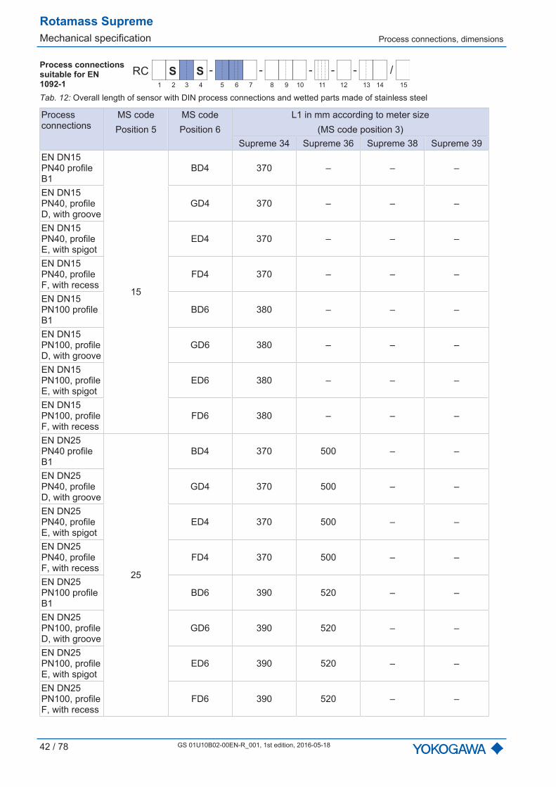
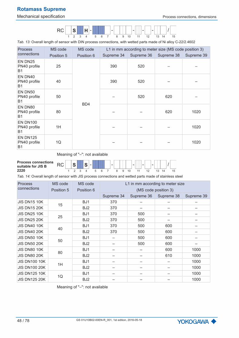
Process connectionssuitable for EN1092-1
- - - - /-RC
1 2 3 4 6 75 9 10 11 12 13 14 158
SS
Tab. 12: Overall length of sensor with DIN process connections and wetted parts made of stainless steel
Processconnections
MS codePosition 5
MS codePosition 6
L1 in mm according to meter size(MS code position 3)
Supreme 34 Supreme 36 Supreme 38 Supreme 39EN DN15PN40 profileB1
15
BD4 370 – – –
EN DN15PN40, profileD, with groove
GD4 370 – – –
EN DN15PN40, profileE, with spigot
ED4 370 – – –
EN DN15PN40, profileF, with recess
FD4 370 – – –
EN DN15PN100 profileB1
BD6 380 – – –
EN DN15PN100, profileD, with groove
GD6 380 – – –
EN DN15PN100, profileE, with spigot
ED6 380 – – –
EN DN15PN100, profileF, with recess
FD6 380 – – –
EN DN25PN40 profileB1
25
BD4 370 500 – –
EN DN25PN40, profileD, with groove
GD4 370 500 – –
EN DN25PN40, profileE, with spigot
ED4 370 500 – –
EN DN25PN40, profileF, with recess
FD4 370 500 – –
EN DN25PN100 profileB1
BD6 390 520 – –
EN DN25PN100, profileD, with groove
GD6 390 520 – –
EN DN25PN100, profileE, with spigot
ED6 390 520 – –
EN DN25PN100, profileF, with recess
FD6 390 520 – –

Process connections, dimensions
Rotamass SupremeMechanical specification
GS 01U10B02-00EN-R_001, 1st edition, 1st edition, 2016-05-18 43 / 78
Processconnections
MS codePosition 5
MS codePosition 6
L1 in mm according to meter size(MS code position 3)
Supreme 34 Supreme 36 Supreme 38 Supreme 39EN DN40PN40 profileB1
40
BD4 370 500 600 –
EN DN40PN40, profileD, with groove
GD4 370 500 600 –
EN DN40PN40, profileE, with spigot
ED4 370 500 600 –
EN DN40PN40, profileF, with recess
FD4 370 500 600 –
EN DN40PN100 profileB1
BD6 450 560 620 –
EN DN40PN100, profileD, with groove
GD6 450 560 620 –
EN DN40PN100, profileE, with spigot
ED6 450 560 620 –
EN DN40PN100, profileF, with recess
FD6 450 560 620 –
Rotamass SupremeMechanical specification Process connections, dimensions
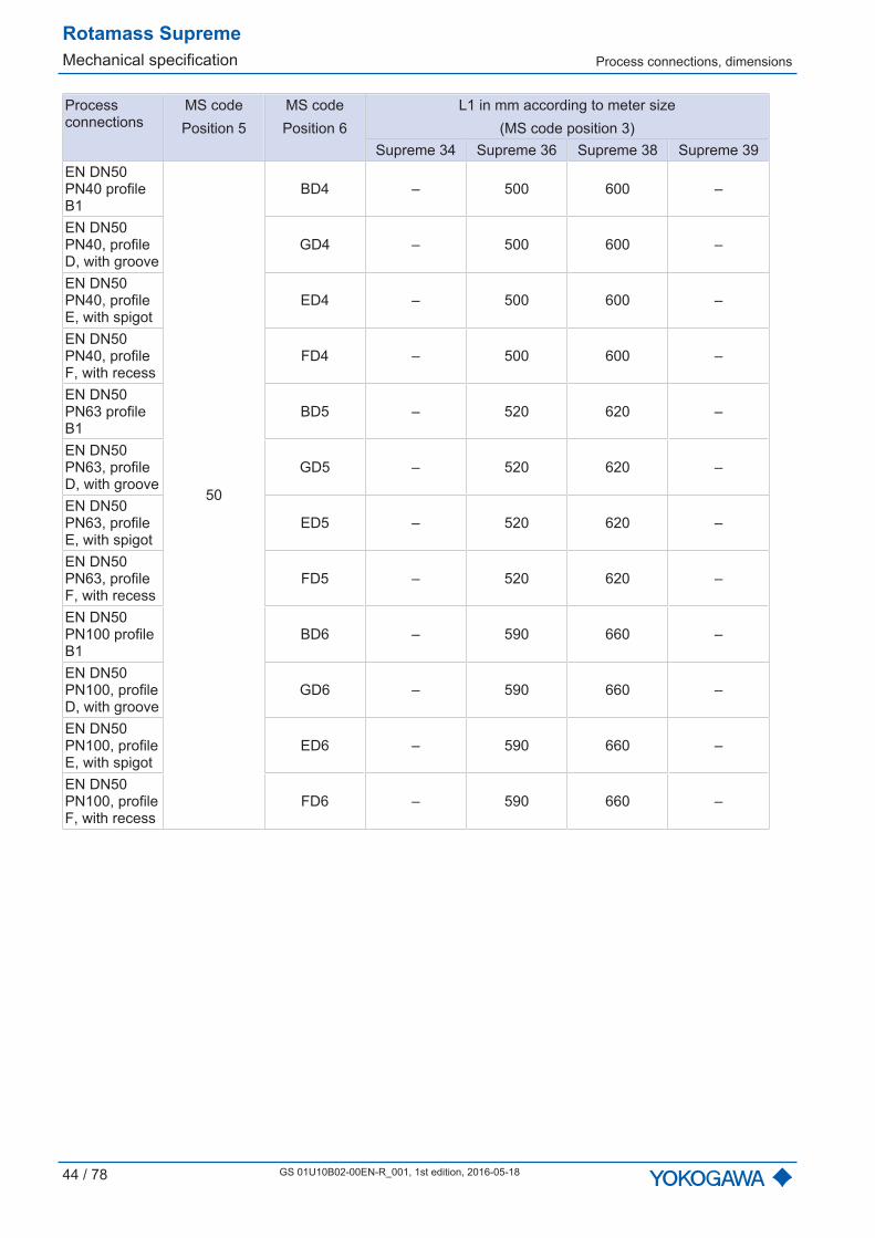
44 / 78 GS 01U10B02-00EN-R_001, 1st edition, 2016-05-18
Processconnections
MS codePosition 5
MS codePosition 6
L1 in mm according to meter size(MS code position 3)
Supreme 34 Supreme 36 Supreme 38 Supreme 39EN DN50PN40 profileB1
50
BD4 – 500 600 –
EN DN50PN40, profileD, with groove
GD4 – 500 600 –
EN DN50PN40, profileE, with spigot
ED4 – 500 600 –
EN DN50PN40, profileF, with recess
FD4 – 500 600 –
EN DN50PN63 profileB1
BD5 – 520 620 –
EN DN50PN63, profileD, with groove
GD5 – 520 620 –
EN DN50PN63, profileE, with spigot
ED5 – 520 620 –
EN DN50PN63, profileF, with recess
FD5 – 520 620 –
EN DN50PN100 profileB1
BD6 – 590 660 –
EN DN50PN100, profileD, with groove
GD6 – 590 660 –
EN DN50PN100, profileE, with spigot
ED6 – 590 660 –
EN DN50PN100, profileF, with recess
FD6 – 590 660 –

Process connections, dimensions
Rotamass SupremeMechanical specification
GS 01U10B02-00EN-R_001, 1st edition, 1st edition, 2016-05-18 45 / 78
Processconnections
MS codePosition 5
MS codePosition 6
L1 in mm according to meter size(MS code position 3)
Supreme 34 Supreme 36 Supreme 38 Supreme 39EN DN80PN40 profileB1
80
BD4 – – 610 1000
EN DN80PN40, profileD, with groove
GD4 – – 610 1000
EN DN80PN40, profileE, with spigot
ED4 – – 610 1000
EN DN80PN40, profileF, with recess
FD4 – – 610 1000
EN DN80PN63 profileB1
BD5 – – 620 1000
EN DN80PN63, profileD, with groove
GD5 – – 620 1000
EN DN80PN63, profileE, with spigot
ED5 – – 620 1000
EN DN80PN63, profileF, with recess
FD5 – – 620 1000
EN DN80PN100 profileB1
BD6 – – 730 1000
EN DN80PN100, profileD, with groove
GD6 – – 730 1000
EN DN80PN100, profileE, with spigot
ED6 – – 730 1000
EN DN80PN100, profileF, with recess
FD6 – – 730 1000
Rotamass SupremeMechanical specification Process connections, dimensions
46 / 78 GS 01U10B02-00EN-R_001, 1st edition, 2016-05-18
Processconnections
MS codePosition 5
MS codePosition 6
L1 in mm according to meter size(MS code position 3)
Supreme 34 Supreme 36 Supreme 38 Supreme 39EN DN100PN40 profileB1
1H
BD4 – – – 1000
EN DN100PN40, profileD, with groove
GD4 – – – 1000
EN DN100PN40, profileE, with spigot
ED4 – – – 1000
EN DN100PN40, profileF, with recess
FD4 – – – 1000
EN DN100PN63 profileB1
BD5 – – – 1000
EN DN100PN63, profileD, with groove
GD5 – – – 1000
EN DN100PN63, profileE, with spigot
ED5 – – – 1000
EN DN100PN63, profileF, with recess
FD5 – – – 1000
EN DN100PN100 profileB1
BD6 – – – 1050
EN DN100PN100, profileD, with groove
GD6 – – – 1050
EN DN100PN100, profileE, with spigot
ED6 – – – 1050
EN DN100PN100, profileF, with recess
FD6 – – – 1050
Process connections, dimensions
Rotamass SupremeMechanical specification
GS 01U10B02-00EN-R_001, 1st edition, 1st edition, 2016-05-18 47 / 78
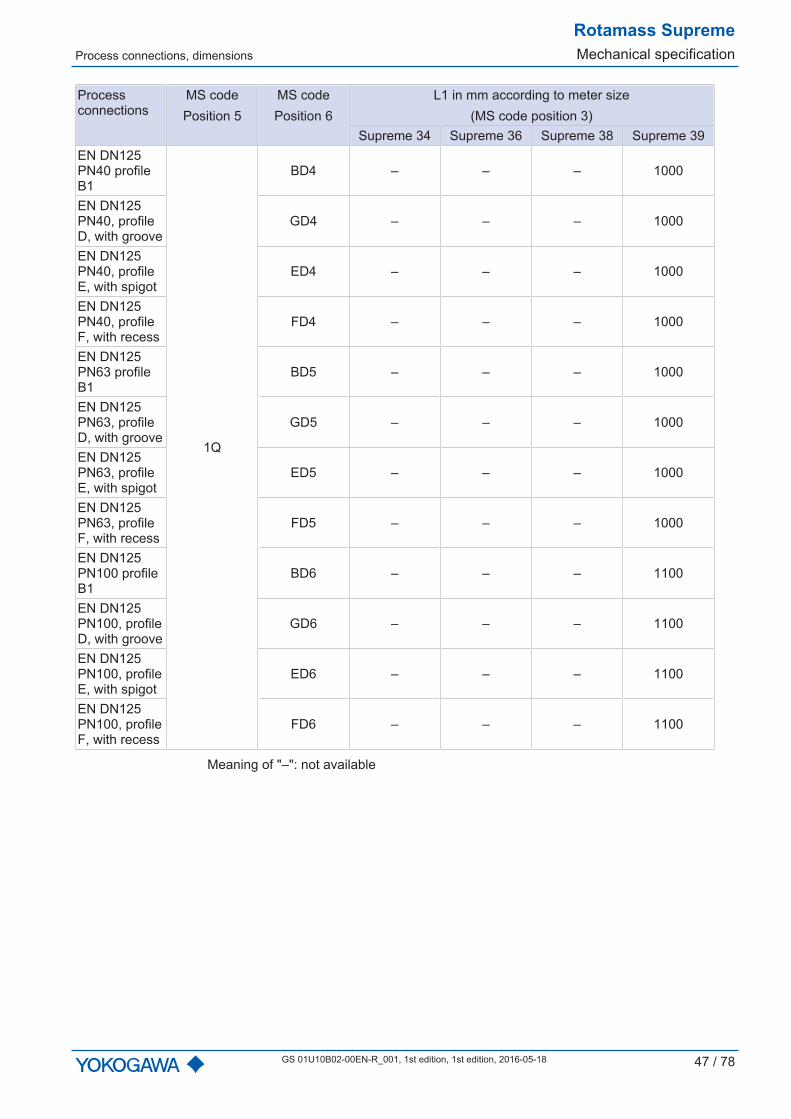
Processconnections
MS codePosition 5
MS codePosition 6
L1 in mm according to meter size(MS code position 3)
Supreme 34 Supreme 36 Supreme 38 Supreme 39EN DN125PN40 profileB1
1Q
BD4 – – – 1000
EN DN125PN40, profileD, with groove
GD4 – – – 1000
EN DN125PN40, profileE, with spigot
ED4 – – – 1000
EN DN125PN40, profileF, with recess
FD4 – – – 1000
EN DN125PN63 profileB1
BD5 – – – 1000
EN DN125PN63, profileD, with groove
GD5 – – – 1000
EN DN125PN63, profileE, with spigot
ED5 – – – 1000
EN DN125PN63, profileF, with recess
FD5 – – – 1000
EN DN125PN100 profileB1
BD6 – – – 1100
EN DN125PN100, profileD, with groove
GD6 – – – 1100
EN DN125PN100, profileE, with spigot
ED6 – – – 1100
EN DN125PN100, profileF, with recess
FD6 – – – 1100
Meaning of "–": not available
Rotamass SupremeMechanical specification Process connections, dimensions
48 / 78 GS 01U10B02-00EN-R_001, 1st edition, 2016-05-18
- - - - /-RC
1 2 3 4 6 75 9 10 11 12 13 14 158
HS
Tab. 13: Overall length of sensor with DIN process connections, with wetted parts made of Ni alloy C-22/2.4602
Processconnections
MS codePosition 5
MS codePosition 6
L1 in mm according to meter size (MS code position 3)Supreme 34 Supreme 36 Supreme 38 Supreme 39
EN DN25PN40 profileB1
25
BD4
390 520 – –
EN DN40PN40 profileB1
40 390 520 – –
EN DN50PN40 profileB1
50 – 520 620 –
EN DN80PN40 profileB1
80 – – 620 1020
EN DN100PN40 profileB1
1H – – – 1020
EN DN125PN40 profileB1
1Q – – – 1020
Meaning of "–": not available
Process connectionssuitable for JIS B2220
- - - - /-RC
1 2 3 4 6 75 9 10 11 12 13 14 158
SS
Tab. 14: Overall length of sensor with JIS process connections and wetted parts made of stainless steel
Processconnections
MS codePosition 5
MS codePosition 6
L1 in mm according to meter size(MS code position 3)
Supreme 34 Supreme 36 Supreme 38 Supreme 39JIS DN15 10K
15BJ1 370 – – –
JIS DN15 20K BJ2 370 – – –JIS DN25 10K
25BJ1 370 500 – –
JIS DN25 20K BJ2 370 500 – –JIS DN40 10K
40BJ1 370 500 600 –
JIS DN40 20K BJ2 370 500 600 –JIS DN50 10K
50BJ1 – 500 600 –
JIS DN50 20K BJ2 – 500 600 –JIS DN80 10K
80BJ1 – – 600 1000
JIS DN80 20K BJ2 – – 610 1000JIS DN100 10K
1HBJ1 – – – 1000
JIS DN100 20K BJ2 – – – 1000JIS DN125 10K
1QBJ1 – – – 1000
JIS DN125 20K BJ2 – – – 1000
Meaning of "–": not available
Process connections, dimensions
Rotamass SupremeMechanical specification
GS 01U10B02-00EN-R_001, 1st edition, 1st edition, 2016-05-18 49 / 78
- - - - /-RC
1 2 3 4 6 75 9 10 11 12 13 14 158
HS
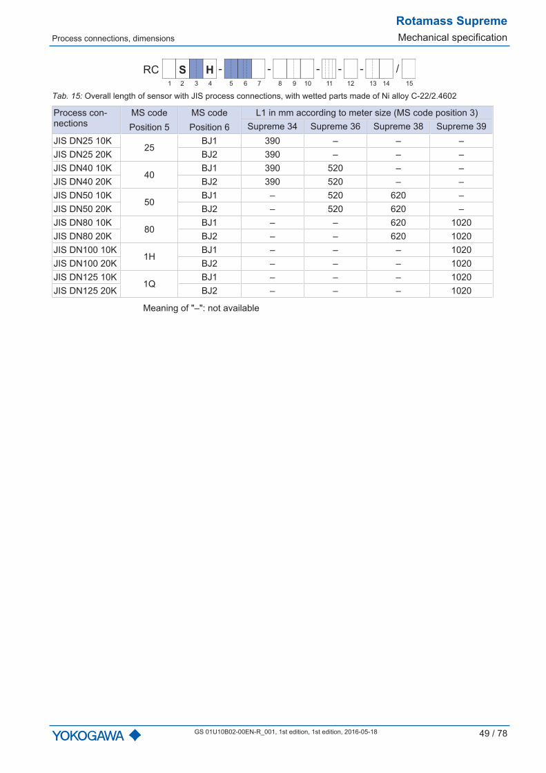
Tab. 15: Overall length of sensor with JIS process connections, with wetted parts made of Ni alloy C-22/2.4602
Process con-nections
MS codePosition 5
MS codePosition 6
L1 in mm according to meter size (MS code position 3)Supreme 34 Supreme 36 Supreme 38 Supreme 39
JIS DN25 10K25
BJ1 390 – – –JIS DN25 20K BJ2 390 – – –JIS DN40 10K
40BJ1 390 520 – –
JIS DN40 20K BJ2 390 520 – –JIS DN50 10K
50BJ1 – 520 620 –
JIS DN50 20K BJ2 – 520 620 –JIS DN80 10K
80BJ1 – – 620 1020
JIS DN80 20K BJ2 – – 620 1020JIS DN100 10K
1HBJ1 – – – 1020
JIS DN100 20K BJ2 – – – 1020JIS DN125 10K
1QBJ1 – – – 1020
JIS DN125 20K BJ2 – – – 1020
Meaning of "–": not available

Rotamass SupremeMechanical specification Process connections, dimensions
50 / 78 GS 01U10B02-00EN-R_001, 1st edition, 2016-05-18
Process connectionssuitable for JPI - - - - /-RC
1 2 3 4 6 75 9 10 11 12 13 14 158
SS
Tab. 16: Overall length of sensor with JPI process connections and wetted parts made of stainlesssteel
Internalthread
MS codePosition 5
MS codePosition 6
L1 in mm according to meter size(MS code position 3)
Supreme34
Supreme36
Supreme38
Supreme39
JPI ½"class 150
15
BP1 370 – – –
JPI ½"class 300 BP2 370 – – –
JPI ½"class 600 BP4 380 – – –
JPI 1" class150
25
BP1 370 500 – –
JPI 1" class300 BP2 370 500 – –
JPI 1" class600 BP4 390 520 – –
JPI 1½"class 150
40
BP1 380 500 600 –
JPI 1½"class 300 BP2 380 510 600 –
JPI 1½"class 600 BP4 400 530 620 –
JPI 2" class150
50
BP1 – 510 600 –
JPI 2" class300 BP2 – 510 600 –
JPI 2" class600 BP4 – 540 630 –
JPI 2½"class 150
65
BP1 – – 610 –
JPI 2½"class 300 BP2 – – 610 –
JPI 2½"class 600 BP4 – – 640 –
JPI 3" class150
80
BP1 – – 610 1000
JPI 3" class300 BP2 – – 620 1000
JPI 3" class600 BP4 – – 640 1000
JPI 4" class150
1H
BP1 – – – 1000
JPI 4" class300 BP2 – – – 1000
JPI 4" class600 BP4 – – – 1030

Transmitter dimensions
Rotamass SupremeMechanical specification
GS 01U10B02-00EN-R_001, 1st edition, 1st edition, 2016-05-18 51 / 78
Internalthread
MS codePosition 5
MS codePosition 6
L1 in mm according to meter size(MS code position 3)
Supreme34
Supreme36
Supreme38
Supreme39
JPI 5" class150
1QBP1 – – – 1000
JPI 5" class300 BP2 – – – 1000
Meaning of "–": not available
Process connectionswith internal thread - - - - /-RC
1 2 3 4 6 75 9 10 11 12 13 14 158
SS
Tab. 17: Overall length of sensor with wetted parts made of stainless steel
Internalthread
MS codePosition 5
MS codePosition 6
L1 in mm according to meter size(MS code position 3)
Supreme34
Supreme36
Supreme38
Supreme39
G ⅜" 08
TG9
390 – – –G ½" 15 390 – – –G ¾" 20 390 – – –G 1" 25 390 – – –
Meaning of "–": not available
6.4 Transmitter dimensions
19
1,7
17
5
123
14
0
240,9
42 96,2
69,7
42
42
23
14
9,5
87,8 73
12
8
60
34
4x M
6
19
1,7
17
5
123
14
0
220,9
42 96,2
69,7
42
42
23
14
9,5
67,8 73
12
8
60
34
4x M
6
Fig. 24: Dimensions of transmitter in mm (left: transmitter with display, right: transmitter without dis-play)

Rotamass SupremeMechanical specification Transmitter dimensions
52 / 78 GS 01U10B02-00EN-R_001, 1st edition, 2016-05-18
10098
104
DN50
Fig. 25: Dimensions of transmitter in mm, attached by sheet metal console (bracket)
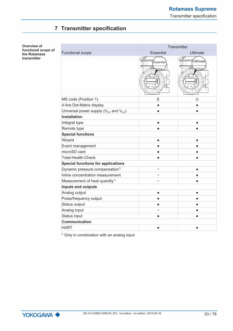
Rotamass SupremeTransmitter specification
GS 01U10B02-00EN-R_001, 1st edition, 1st edition, 2016-05-18 53 / 78
7 Transmitter specification
Overview offunctional scope ofthe Rotamasstransmitter
TransmitterFunctional scope Essential Ultimate
YOKOGAWA
Essential
YOKOGAWA
Essential
YOKOGAWA
Ultimate
YOKOGAWA
Ultimate
MS code (Position 1) E U4-line Dot-Matrix display Universal power supply (VDC and VAC) InstallationIntegral type Remote type Special functionsWizard Event management microSD card Total-Health-Check Special functions for applicationsDynamic pressure compensation1) − Inline concentration measurement − Measurement of heat quantity1) − Inputs and outputsAnalog output Pulse/frequency output Status output Analog input − Status input CommunicationHART
1) Only in combination with an analog input
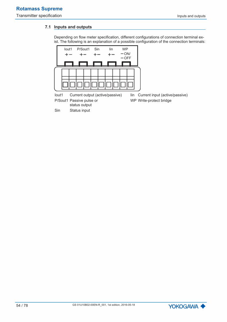
Rotamass SupremeTransmitter specification Inputs and outputs
54 / 78 GS 01U10B02-00EN-R_001, 1st edition, 2016-05-18
7.1 Inputs and outputs
Depending on flow meter specification, different configurations of connection terminal ex-ist. The following is an explanation of a possible configuration of the connection terminals:
WP
ON/
OFF
SinIout1 P/Sout1 Iin
Iout1 Current output (active/passive) Iin Current input (active/passive)P/Sout1 Passive pulse or
status outputWP Write-protect bridge
Sin Status input

Inputs and outputs
Rotamass SupremeTransmitter specification
GS 01U10B02-00EN-R_001, 1st edition, 1st edition, 2016-05-18 55 / 78
7.1.1 Output signalsGalvanic isolation All circuits for inputs, outputs and power supply are galvanically isolated from each other.Active currentoutput lout
One or two current outputs are available depending on MS code position 13.
Depending on the measured value, the active current output delivers 4...20 mA.
It may be used for output of the following measured values (see also the correspondingsoftware instruction manual):
Flow rate (mass, volume, net partial component flow of a mixture) Density Temperature Pressure Concentration
For HART communication devices, it is supplied on the current output lout1. The currentoutput may be operated in compliance with the NAMUR NE43 standard. For details seee.g., software instruction manual HART IM01U10S01-00-R (chapter "Configuration ofanalog output 1")
ValueOutput current 2.4...21.6 mALoad resistance ≤ 750 ΩLoad resistance for secure HART communi-cation 230...600 Ω
Additive maximum deviation 0.05 % of maximum currentAdditive deviation in case of 20 °C deviationof ambient temperature 0.05 % of maximum current per 10 °C
Iout+
Iout-
ROTAMASS
1
Fig. 26: Active current output connection lout
① Receiver

Rotamass SupremeTransmitter specification Inputs and outputs
56 / 78 GS 01U10B02-00EN-R_001, 1st edition, 2016-05-18
Passive currentoutput lout
Current output: 4...20 mA
ValueOutput current 2.4...21.6 mAExternal power supply 10.5...32 VDC
Load resistance for secure HARTcommunication 230...600 Ω
Load resistance at current output ≤ 911 ΩAdditive maximum deviation 0.05 % of maximum currentAdditive deviation in case of 20 °C deviationof ambient temperature 0.05 % of maximum current per 10 °C
R =U - 10.5 V
0.0236 A
911
U in V
3210.5
R in
Ω
0
Fig. 27: Maximum load resistance as a function of receiver output current
R Load resistanceU Output voltage of receiver
The diagram shows the maximum load resistance R as a function of voltage U of the con-nected voltage source. Higher load resistances are allowed with higher power supply val-ues. The usable zone for passive power output operation is indicated by the hatchedarea.
U
R
Iout+
Iout-
ROTAMASS
Fig. 28: Passive current output connection lout

Inputs and outputs
Rotamass SupremeTransmitter specification
GS 01U10B02-00EN-R_001, 1st edition, 1st edition, 2016-05-18 57 / 78
Active pulse output P/Sout
Connection of an electronic counterMaximum voltage and correct polarity must be observed for wiring.
ValueLoad resistance ≥ 1 kΩAllowed load current ≤ 200 mAInternal power supply 24 VDC ±20 %Maximum pulse rate 12500 pulses/sFrequency range 0...12.5 kHz
P/Sout+
P/Sout-
24 V
0 V
1
ROTAMASS
2
Fig. 29: Active pulse output connection P/Sout
① Load resistance② Electronic counter
Connection of an electromechanical counter
ValueMaximum current 150 mAAverage current ≤ 30 mAInternal power supply 24 VDC ±20 %Maximum pulse rate 2 pulses/sPulse length 20, 33, 50, 100 ms
P/Sout+
P/Sout-
24 V
0 V
1
ROTAMASS
2
Fig. 30: Active pulse output P/Sout connection with electromechanical counter
① Protective diode② Electromechanical counter
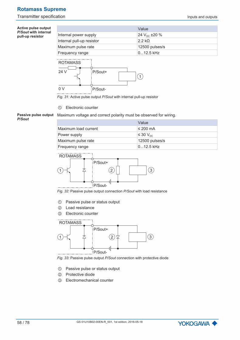
Rotamass SupremeTransmitter specification Inputs and outputs
58 / 78 GS 01U10B02-00EN-R_001, 1st edition, 2016-05-18
Active pulse output P/Sout with internalpull-up resistor
ValueInternal power supply 24 VDC ±20 %Internal pull-up resistor 2.2 kΩMaximum pulse rate 12500 pulses/sFrequency range 0...12.5 kHz
1
P/Sout+
P/Sout-
24 V
0 V
ROTAMASS
Fig. 31: Active pulse output P/Sout with internal pull-up resistor
① Electronic counter
Passive pulse output P/Sout
Maximum voltage and correct polarity must be observed for wiring.
ValueMaximum load current ≤ 200 mAPower supply ≤ 30 VDC
Maximum pulse rate 12500 pulses/sFrequency range 0...12.5 kHz
ROTAMASS
P/Sout+
P/Sout-
321
Fig. 32: Passive pulse output connection P/Sout with load resistance
① Passive pulse or status output② Load resistance③ Electronic counter
ROTAMASS
P/Sout+
P/Sout-
321
Fig. 33: Passive pulse output P/Sout connection with protective diode
① Passive pulse or status output② Protective diode③ Electromechanical counter
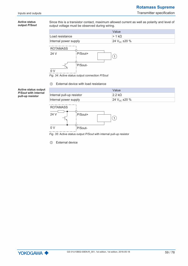
Inputs and outputs
Rotamass SupremeTransmitter specification
GS 01U10B02-00EN-R_001, 1st edition, 1st edition, 2016-05-18 59 / 78
Active status output P/Sout
Since this is a transistor contact, maximum allowed current as well as polarity and level ofoutput voltage must be observed during wiring.
ValueLoad resistance > 1 kΩInternal power supply 24 VDC ±20 %
P/Sout+
P/Sout-
24 V
0 V
1
ROTAMASS
Fig. 34: Active status output connection P/Sout
① External device with load resistance
Active status output P/Sout with internalpull-up resistor
ValueInternal pull-up resistor 2.2 kΩInternal power supply 24 VDC ±20 %
1
P/Sout+
P/Sout-
24 V
0 V
ROTAMASS
Fig. 35: Active status output P/Sout with internal pull-up resistor
① External device

Rotamass SupremeTransmitter specification Inputs and outputs
60 / 78 GS 01U10B02-00EN-R_001, 1st edition, 2016-05-18
Passive statusoutput P/Sout
Since this is a transistor contact, maximum allowed power supply, its polarity as well asmaximum allowed current must be observed during wiring.
ValueAllowed load current ≤ 200 mAPower supply ≤ 30 VDC
P/Sout+ or Sout+
P/Sout- or Sout-
1
ROTAMASS
Fig. 36: Passive status output connection P/Sout with protective diode
① External device
A relay must be connected in series to switch alternating voltage.
P/Sout- or Sout-
P/Sout+ or Sout+
2
3
1
ROTAMASS
4
Fig. 37: Passive status output connection P/Sout for solenoid valve circuit
① Relay② Solenoid valve③ Magnetic valve power supply④ Protective diode
Passive pulse orstatus output P/Sout(NAMUR)
According to EN 60947-5-6 (previously NAMUR, worksheet NA001)
10kΩ
1kΩROTAMASS
P/Sout+
P/Sout-
21
Fig. 38: Passive pulse or status output with switching amplifier connected in series
① Passive pulse or status output② Switching amplifier
What to do in case ofmalfunction
Statuses for all outputs in case of alarms, warnings or error are freely selectable. In thisregard, it is necessary to refer to the Event Management chapter in the correspondingsoftware instruction manual, e.g. HART IM01U10C03-00EN.
Suppression ofcreep
The limit value for low cut is freely selectable.
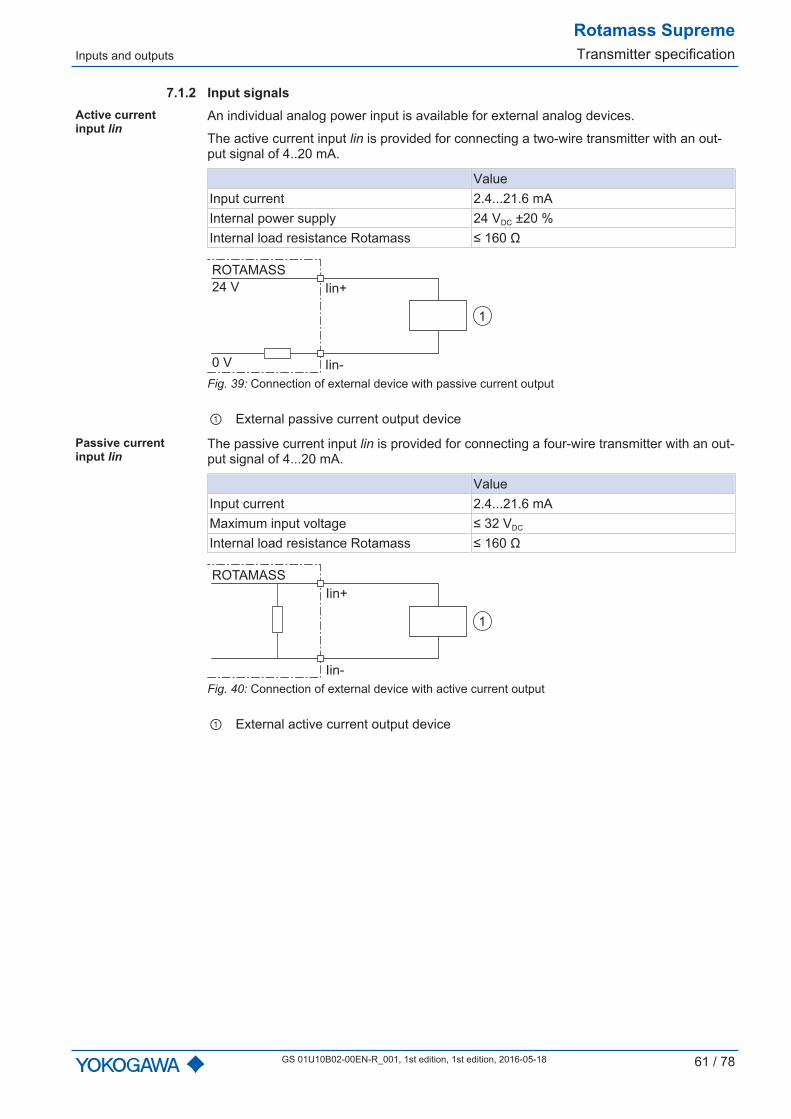
Inputs and outputs
Rotamass SupremeTransmitter specification
GS 01U10B02-00EN-R_001, 1st edition, 1st edition, 2016-05-18 61 / 78
7.1.2 Input signalsActive current input lin
An individual analog power input is available for external analog devices.
The active current input lin is provided for connecting a two-wire transmitter with an out-put signal of 4..20 mA.
ValueInput current 2.4...21.6 mAInternal power supply 24 VDC ±20 %Internal load resistance Rotamass ≤ 160 Ω
Iin+
Iin-
24 V
ROTAMASS
0 V
1
Fig. 39: Connection of external device with passive current output
① External passive current output device
Passive currentinput lin
The passive current input lin is provided for connecting a four-wire transmitter with an out-put signal of 4...20 mA.
ValueInput current 2.4...21.6 mAMaximum input voltage ≤ 32 VDC
Internal load resistance Rotamass ≤ 160 Ω
Iin+
Iin-
ROTAMASS
1
Fig. 40: Connection of external device with active current output
① External active current output device
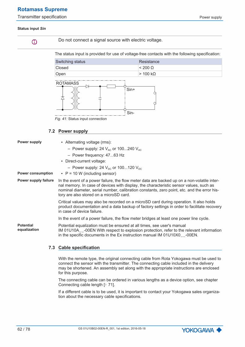
Rotamass SupremeTransmitter specification Power supply
62 / 78 GS 01U10B02-00EN-R_001, 1st edition, 2016-05-18
Status input Sin
Do not connect a signal source with electric voltage.
The status input is provided for use of voltage-free contacts with the following specification:
Switching status ResistanceClosed < 200 ΩOpen > 100 kΩ
ROTAMASS
Sin+
Sin-
Fig. 41: Status input connection
7.2 Power supply
Power supply Alternating voltage (rms):– Power supply: 24 VAC or 100...240 VAC
– Power frequency: 47...63 Hz Direct-current voltage:
– Power supply: 24 VDC or 100...120 VDC
Power consumption P = 10 W (including sensor)Power supply failure In the event of a power failure, the flow meter data are backed up on a non-volatile inter-
nal memory. In case of devices with display, the characteristic sensor values, such asnominal diameter, serial number, calibration constants, zero point, etc. and the error his-tory are also stored on a microSD card.
Critical values may also be recorded on a microSD card during operation. It also holdsproduct documentation and a data backup of factory settings in order to facilitate recoveryin case of device failure.
In the event of a power failure, the flow meter bridges at least one power line cycle.Potentialequalization
Potential equalization must be ensured at all times, see user's manualIM 01U10A-00EN With respect to explosion protection, refer to the relevant informationin the specific documents in the Ex instruction manual IM 01U10X0-00EN.
7.3 Cable specification
With the remote type, the original connecting cable from Rota Yokogawa must be used toconnect the sensor with the transmitter. The connecting cable included in the deliverymay be shortened. An assembly set along with the appropriate instructions are enclosedfor this purpose.
The connecting cable can be ordered in various lengths as a device option, see chapterConnecting cable length [ 71].
If a different cable is to be used, it is important to contact your Yokogawa sales organiza-tion about the necessary cable specifications.

Rotamass SupremeApprovals and declarations of conformity
GS 01U10B02-00EN-R_001, 1st edition, 1st edition, 2016-05-18 63 / 78
8 Approvals and declarations of conformity
CE marking The Rotamass Coriolis flow meter meets the statutory requirements of the applicable EUDirectives. By attaching the CE mark, Rota Yokogawa confirms conformity of the field in-strument with the requirements of the applicable EU Directives. The EU Declaration ofConformity is enclosed with the product on a data carrier.
RCM Rotamass Coriolis flow meter meets the EMC requirements of the Australian Communi-cations and Media Authority (ACMA).
Ex approvals All data relevant for explosion protection are included in separate Ex instruction manuals.Pressure equipmentapprovals
The Rotamass Coriolis flow meter is in compliance with the statutory requirements of theapplicable EU Pressure Equipment Directive (PED).

Rotamass SupremeOrdering information MS code
64 / 78 GS 01U10B02-00EN-R_001, 1st edition, 2016-05-18
9 Ordering information
9.1 MS code
The MS code of the Rotamass TI is explained below.
Items 1 through 14 are mandatory entries and must be specified at the time of ordering.
Device options (item 15) can be selected and specified individually by separating themwith slashes.
- - - - /-RC
1 2 3 4 6 75 9 10 11 12 13 14 158
1. Transmitter2. Sensor3. Meter size4. Material wetted parts5. Process connection size6. Process connection type7. Sensor housing material8. Medium temperature range9. Mass flow and density accuracy10. Design and housing11. Ex approval12. Cable entries13. Communication type and I/O14. Display15. Options
Details are available in the general Specifications of the corresponding Rotamass series.
9.1.1 Transmitter
- - - - /-RC
1 2 3 4 6 75 9 10 11 12 13 14 158
MS codePosition 1
Transmitter
E EssentialU Ultimate
9.1.2 Sensor
- - - - /-RC
1 2 3 4 6 75 9 10 11 12 13 14 158
MS codePosition 2
Sensor
S Supreme
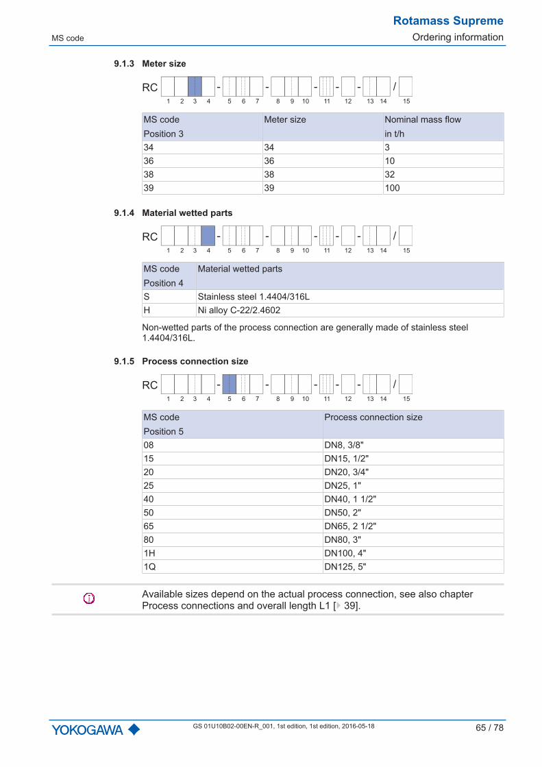
MS code
Rotamass SupremeOrdering information
GS 01U10B02-00EN-R_001, 1st edition, 1st edition, 2016-05-18 65 / 78
9.1.3 Meter size
- - - - /-RC
1 2 3 4 6 75 9 10 11 12 13 14 158
MS codePosition 3
Meter size Nominal mass flowin t/h
34 34 336 36 1038 38 3239 39 100
9.1.4 Material wetted parts
- - - - /-RC
1 2 3 4 6 75 9 10 11 12 13 14 158
MS codePosition 4
Material wetted parts
S Stainless steel 1.4404/316LH Ni alloy C-22/2.4602
Non-wetted parts of the process connection are generally made of stainless steel1.4404/316L.
9.1.5 Process connection size
- - - - /-RC
1 2 3 4 6 75 9 10 11 12 13 14 158
MS codePosition 5
Process connection size
08 DN8, 3/8"15 DN15, 1/2"20 DN20, 3/4"25 DN25, 1"40 DN40, 1 1/2"50 DN50, 2"65 DN65, 2 1/2"80 DN80, 3"1H DN100, 4"1Q DN125, 5"
Available sizes depend on the actual process connection, see also chapterProcess connections and overall length L1 [ 39].

Rotamass SupremeOrdering information MS code
66 / 78 GS 01U10B02-00EN-R_001, 1st edition, 2016-05-18
9.1.6 Process connection type
- - - - /-RC
1 2 3 4 6 75 9 10 11 12 13 14 158
MS codePosition 6
Type Process connections
BA1Flanges suitable for ASMEB16.5
ASME flange class 150BA2 ASME flange class 300BA4 ASME flange class 600CA4 ASME flange class 600, ring jointBD4
Flange suitable for EN 1092-1
EN flange PN40, profile B1ED4 EN flange PN40, profile E, with spigotFD4 EN flange PN40, profile F, with recessGD4 EN flange PN40, profile D, with grooveBD5 EN flange PN63, profile B1ED5 EN flange PN63, profile E, with spigotFD5 EN flange PN63, profile F, with recessGD5 EN flange PN63, profile D, with grooveBD6 EN flange PN100, profile B1ED6 EN flange PN100, profile E, with spigotFD6 EN flange PN100, profile F, with recessGD6 EN flange PN100, profile D, with grooveBJ1
Flange suitable for JIS B 2220JIS flange 10K
BJ2 JIS flange 20KBP1
Flange suitable for JPIJPI flange class 150
BP2 JPI flange class 300BP4 JPI flange class 600TG9
Process connections withinternal thread
Process connection with internal thread G
TT9 Process connection with internal threadNPT
9.1.7 Sensor housing material
- - - - /-RC
1 2 3 4 6 75 9 10 11 12 13 14 158
MS codePosition 7
Housing material
0 Stainless steel 1.4301/304

MS code
Rotamass SupremeOrdering information
GS 01U10B02-00EN-R_001, 1st edition, 1st edition, 2016-05-18 67 / 78
9.1.8 Medium temperature range
- - - - /-RC
1 2 3 4 6 75 9 10 11 12 13 14 158
MS codePosition 8
Temperature range Medium temperature range
0 StandardIntegral type: -50...150 °CRemote type: -70...150 °C
2 Mid-range -70...230 °C3 High 0...350 °C
For temperature range limits, see chapter Medium temperature range [ 25].
9.1.9 Mass flow and density accuracy
- - - - /-RC
1 2 3 4 6 75 9 10 11 12 13 14 158
Medium MS codePosition 9
Maximum deviation MS codePosition 1Mass flow
Dflat in %Density
in g/l
Liquid
E7 0.2 4 ED7 0.15 4 E, UC6
0.1
3 UC5 2 UC3 1 UC2 0.5 U
Gas70 0.75 – E50 0.5 – U
Devices with value 2 in MS code position 9 receive an additional density calibration witha corresponding certificate.
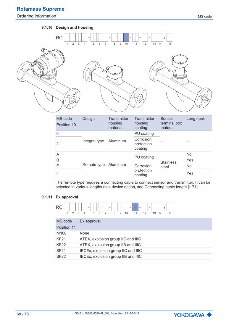
Rotamass SupremeOrdering information MS code
68 / 78 GS 01U10B02-00EN-R_001, 1st edition, 2016-05-18
9.1.10 Design and housing
- - - - /-RC
1 2 3 4 6 75 9 10 11 12 13 14 158
MS codePosition 10
Design Transmitter housing material
Transmitterhousingcoating
Sensorterminal box material
Long neck
0
Integral type Aluminum
PU coating
‒ ‒2
Corrosionprotectioncoating
A
Remote type Aluminum
PU coatingStainlesssteel
NoB YesE Corrosion
protectioncoating
No
F Yes
The remote type requires a connecting cable to connect sensor and transmitter. It can beselected in various lengths as a device option, see Connecting cable length [ 71].
9.1.11 Ex approval
- - - - /-RC
1 2 3 4 6 75 9 10 11 12 13 14 158
MS codePosition 11
Ex approval
NN00 NoneKF21 ATEX, explosion group IIC and IIICKF22 ATEX, explosion group IIB and IIICSF21 IECEx, explosion group IIC and IIICSF22 IECEx, explosion group IIB and IIIC
MS code
Rotamass SupremeOrdering information
GS 01U10B02-00EN-R_001, 1st edition, 1st edition, 2016-05-18 69 / 78
9.1.12 Cable entries
- - - - /-RC
1 2 3 4 6 75 9 10 11 12 13 14 158
MS codePosition 12
Cable entries
2 ANSI 1/2" NPT4 ISO M20x1.5
9.1.13 Inputs and outputs
- - - - /-RC
1 2 3 4 6 75 9 10 11 12 13 14 158
HART I/O MS codePosition 13
Connection terminal assignmentI/O1 +/- I/O2 +/- I/O3 +/- I/O4 +/- WP
JAIout1Active
P/Sout1Passive
– – Write-protect
JBIout1Active
P/Sout1Passive
P/Sout2Passive
Iout2Active
Write-protect
JCIout1Active
P/Sout1Passive
SinIout2Active
Write-protect
JDIout1Active
P/Sout1Passive
SoutPassive
P/Sout2Passive
Write-protect
JEIout1Active
P/Sout1Passive
SinP/Sout2Passive
Write-protect
JFIout1Active
P/Sout1Passive
Sin
P/Sout2ActiveInternal pull-up resistor
Write-protect
JGIout1Active
P/Sout1Passive
SinP/Sout2Active
Write-protect
JHIout1Active
P/Sout1Passive
Iout2Passive
IinActive
Write-protect
JJIout1Active
P/Sout1Passive
P/Sout2Passive
IinActive
Write-protect
JKIout1Active
P/Sout1Passive
SinIinActive
Write-protect
JLIout1Active
P/Sout1Passive
Iout2Passive
IinPassive
Write-protect
JMIout1Active
P/Sout1Passive
P/Sout2Passive
IinPassive
Write-protect
JNIout1Active
P/Sout1Passive
SinIinPassive
Write-protect
Iout1 Active or passive current output with HART communicationIout2 Active or passive current outputIin Active or passive current input
Rotamass SupremeOrdering information MS code
70 / 78 GS 01U10B02-00EN-R_001, 1st edition, 2016-05-18
P/Sout1 Passive pulse or status outputP/Sout2 Active or passive pulse or status outputSin Status inputSout Status output
HART I/O, intrinsically safe
MS codePosition 13
Connection terminal assignmentI/O1 +/- I/O2 +/- I/O3 +/- I/O4 +/- WP
JPIout1Passive
P/Sout1Passive
Iout2Passive
– Write-protect
JQIout1Passive
P/Sout1Passive
Iout2Passive
P/Sout2Passive
Write-protect
JRIout1Passive
P/Sout1PassiveNAMUR
Iout2Passive
– Write-protect
JSIout1Passive
P/Sout1PassiveNAMUR
Iout2Passive
P/Sout2PassiveNAMUR
Write-protect
Intrinsically safe outputs are only available in combination with selecting Ex approval ofthe device, see chapter Ex approval [ 68].
9.1.14 Display
- - - - /-RC
1 2 3 4 6 75 9 10 11 12 13 14 158
The display unit includes a slot for the microSD card.
MS codePosition 14
Display
0 Without display1 With display
Devices without a display are available for Essential transmitters only (value E in MS codeposition 1)
Options
Rotamass SupremeOrdering information
GS 01U10B02-00EN-R_001, 1st edition, 1st edition, 2016-05-18 71 / 78
9.2 Options
Additional device options that can be combined may be selected; they are listed sequen-tially in MS code position 15. In this case, each device option is preceded by a slash.
- - - - /-RC
1 2 3 4 6 75 9 10 11 12 13 14 158
The following device options are possible: Connecting cable length, see chapter Connecting cable length [ 71] Customer-specific adaptation of the nameplate, see chapter Additional nameplate in-
formation [ 71] Flow meter presetting with customer parameters, see chapter Presetting of customer
parameters [ 72] Concentration measurement, see chapter Concentration measurement [ 72] Insulation and heat tracing, see chapter Insulation and heat tracing [ 74] Certificates to be supplied, see chapter Certificates [ 74] Positive Material Identification of wetted parts, see chapter Certificates [ 74] Rupture disc, see chapter Rupture disc [ 76] X-ray inspection of flange weld seam, see chapter Certificates [ 75] Tube health check, see chapter Tube health check [ 76] Transmitter housing rotated 180°, see chapter Transmitter housing rotated 180°
[ 77] Measurement of heat quantity, see chapter Measurement of heat quantity [ 77]
9.2.1 Connecting cable lengthWhen ordering the remote type, it is mandatory to always provide the desired connectingcable length.
- - - - /-RC
1 2 3 4 6 75 9 10 11 12 13 14 158
Options SpecificationL000 Specially ordered connecting cableL005 5 m (16.4 ft) cable lengthL010 10 m (32.8 ft) cable lengthL015 15 m (49.2 ft) cable lengthL030 30 m (98.4 ft) cable length
9.2.2 Additional nameplate information
- - - - /-RC
1 2 3 4 6 75 9 10 11 12 13 14 158
Options SpecificationBG Nameplate with customer-specific identification
This marking must be provided by the customer at the time the order is placed.

Rotamass SupremeOrdering information Options
72 / 78 GS 01U10B02-00EN-R_001, 1st edition, 2016-05-18
9.2.3 Presetting of customer parametersRotamass flow meters can be preconfigured with customer-specific data.
- - - - /-RC
1 2 3 4 6 75 9 10 11 12 13 14 158
Options Specification
PSPresetting according to customer parameters.This information must be provided by the customer in the YokogawaFlowConfigurator software at the time the order is placed.
9.2.4 Concentration measurementThe standard concentration measurement (device option CST) can be used for concen-tration measurements of emulsions or suspensions when density of the media involveddepends only on temperature.
The standard concentration measurement can also be used for many low-concentrationsolutions if there is only minor interaction between the liquids or if the miscibility is negligi-ble. For questions regarding a specific application, contact the responsible Yokogawasales organization. The appropriate density coefficients must be determined prior to usingthis option and input into the transmitter. To do so, the recommendation is to determinethe necessary parameters from density data using DTM in the Yokogawa FieldMate pro-gram or the calculation tool inclduded in the delivery.
The advanced concentration measurement is recommended for more complex applica-tions, such as for liquids that interact.
- - - - /-RC
1 2 3 4 6 75 9 10 11 12 13 14 158
Options SpecificationCST Standard concentration measurementAC0 Advanced concentration measurement, customer settingsAC1 Advanced concentration measurement, one default data setAC2 Advanced concentration measurement, two default data setsAC3 Advanced concentration measurement, three default data setsAC4 Advanced concentration measurement, four default data sets
These device options are not available in combination with gas measurement devices(model code position 9 with the values: 70 or 50).
Options with AC are available only for Ultimate transmitters (value U in MS code posi-tion 1).
Sets must be selected for AC1...AC4 options. Not applicable to AC0 option.

Options
Rotamass SupremeOrdering information
GS 01U10B02-00EN-R_001, 1st edition, 1st edition, 2016-05-18 73 / 78
Following is a table that lists possible pre-configured concentrations. The desired datasets must be requested by the customer to the Yokogawa sales organization at the timethe order is placed. The customer is responsible to ensure chemical compatibility of thematerial of the wetted parts with the measured chemicals. For strong acids or oxidizerswhich attack steel pipes a variant with wetted parts made of Ni alloy C-22/2.4602 is nec-essary.
Set Medium A / B
Concentrationrange
Unit Tempera-ture range
in °C
Density rangein kg/l
Data source for density data
C01 Sugar / Water 0...85 °Brix 0...80 0.97...1.45
PTB... Messages 100 5/90: "Thedensity of watery sucrose solu-tions after the introduction of theinternational temperature scaleof 1990 (ITS1990)" Table 5
C02 1) NaOH /Water 0...54 WT% 0...100 0.95...1.58
D´Ans-Lax, Handbook forchemists and physicists Vol.1,3rd edition, 1967
C03 KOH / Water 1...55 WT% 54...100 1.01...1.58
D´Ans-Lax, Handbook forchemists and physicists Vol.1,3rd edition, 1967
C04 NH4NO3 /Water 1...50 WT% 0...80 0.97...1.24 Table of density data on request
C05 NH4NO3 /Water 20...70 WT% 20...100 1.04...1.33 Table of density data on request
C06 1) HCl / Water 22...34 WT% 20...60 1.08...1.17
D´Ans-Lax, Handbook forchemists and physicists Vol.1,3rd edition, 1967
C07 HNO3 / Water 50...67 WT% 10...60 1.26...1.40 Table of density data on request
C09 1) H2O2 / Water 30...75 WT% 4.5...43.5 1.00...1.20 Table of density data on request
C10 1)Ethyleneglycol / Water
10...50 WT% 20...40 1.005...1.085 Table of density data on request
C11 Starch /Water 33...42.5 WT% 35...45 1.14...1.20 Table of density data on request
C12 Methanol /Water 35...60 WT% 0...40 0.89...0.96 Table of density data on request
C20 Alcohol /Water 55...100 VOL% 10...40 0.76...0.94 Table of density data on request
C21 Sugar / Water 40...80 °Brix 75...100 1.15...1.35 Table of density data on request
C30 Alcohol /Water 66...100 WT% 15...40 0.77...0.88 Standard Copersucar 1967
C37 Alcohol /Water 66...100 WT% 10...40 0.772...0.885 Brazilian Standard ABNT
1) We recommend using devices with wetted parts made of nickel alloy C33.

Rotamass SupremeOrdering information Options
74 / 78 GS 01U10B02-00EN-R_001, 1st edition, 2016-05-18
9.2.5 Insulation and heat tracingThese device options are available only for remote type with long neck.
- - - - /-RC
1 2 3 4 6 75 9 10 11 12 13 14 158
Options SpecificationT10 InsulationT21 Insulation and heat tracing, 1/2" ANSI 150T22 Insulation and heat tracing, 1/2" ANSI 300T26 Insulation and heat tracing, DN15 PN40T31 Insulation, heat tracing with ventilation, 1/2" ANSI 150T32 Insulation, heat tracing with ventilation, 1/2" ANSI 300T36 Insulation, heat tracing with ventilation, DN15, PN40
9.2.6 Certificates
- - - - /-RC
1 2 3 4 6 75 9 10 11 12 13 14 158
Accordance withterms of order
Options SpecificationP2 Declaration of compliance with the order 2.1 according to EN 10204
P3 Quality Inspection Certificate (Inspection Certificate 3.1 according to EN 10204)
Material certificates Options Specification
P6 Certificate of Marking Transfer and Raw Material Certificates(Inspection Certificate 3.1 according to EN 10204)
Dye penetration testof weld seams
Options Specification
PT Dye penetration test of process connection weld seams according toDIN EN ISO 3452-1, including certificate
Positive MaterialIdentification of wetted parts
Options Specification
PM Positive Material Identification of wetted parts, including certificate(Inspection Certificate 3.1 according to EN 10204)
Pressure testing Options Specification
P8 Hydrostatic Pressure Test Certificate (Inspection Certificate 3.1 according to EN 10204)
Welding certificates Options Specification
WP
Welding certificates: WPS according to DIN EN ISO 15609-1 WPQR according to DIN EN ISO 15614-1 WQC according to DIN EN 287-1 or DIN EN ISO 6906-4
This device option is not available for devices with wetted parts made of Ni alloyC-22/2.4602.
Only for the butt welding seam between the process connection and the media dispenser.
Options
Rotamass SupremeOrdering information
GS 01U10B02-00EN-R_001, 1st edition, 1st edition, 2016-05-18 75 / 78
Mass flowcalibration
Water is used as medium for calibrating the Rotamass.
Options Specification
K2Customer-specific 5-point mass flow calibration with factory calibrationcertificate (mass flow or volume flow of water). A table listing the de-sired calibration points must be supplied with the order.
K5Customer-specific 10-point mass flow calibration with DAkkS calibra-tion certificate (mass flow or volume flow of water). A table listing thedesired calibration points must be supplied with the order.
Calibrationcertificates
Options Specification
L2The certificate confirms that the delivered instrument has undergone acalibration traceable to national standards, including a list of workingstandards used for calibration. Language: English/Japanese
L3
The certificate confirms that the delivered instrument has undergone acalibration traceable to national standards, including a list of primarystandards to which the delivered product is traceable. Language:English/Japanese
L4
The certificate confirms that the delivered instrument has undergone acalibration traceable to national standards and that the calibration sys-tem of Rota Yokogawa is traceable to national standards. Language:English/Japanese
Surfaces free of oiland grease
Options Specification
H1 Degreasing of wetted surfaces according to ASTM G93-03 (Level C),including test report
Country-specificdelivery
Options Specification
PJ Quality Inspection Certificate according to the "Quality InspectionStandard" of Rotamass TI. Language: English/Japanese
X-ray inspection offlange weld seam
Options Specification
RT
X-ray inspection of flange weld seam according to DIN EN ISO17636-1/BEvaluation according to AD2000HP 5/3 and DIN EN ISO 5817/C,including certificate
This device option is not available for devices with wetted parts made of Ni alloyC-22/2.4602.
In case of the Supreme 34 model with stainless steel wetted parts, where MS code posi-tion 9 includes the value C2, D2, C3 or D3, an X-ray inspection can only be performed onone of the two process connections as a result of structural conditions.
Combinedcertificates
Options Specification
P10
Combination of: P3: Quality Inspection Certificate P6: Certificate of Marking Transfer and Raw Material Certificates P8: Hydrostatic Pressure Test Certificate
P11
Combination of: P3: Quality Inspection Certificate P6: Certificate of Marking Transfer and Raw Material Certificates PM: Positive Material Identification of wetted parts
P12
Combination of: P3: Quality Inspection Certificate P6: Certificate of Marking Transfer and Raw Material Certificates PT: Dye penetration test according to DIN EN ISO 3452-1 P8: Hydrostatic Pressure Test Certificate
Rotamass SupremeOrdering information Options
76 / 78 GS 01U10B02-00EN-R_001, 1st edition, 2016-05-18
Options Specification
P13
Combination of: P3: Quality Inspection Certificate P6: Certificate of Marking Transfer and Raw Material Certificates PT: Dye penetration test according to DIN EN ISO 3452-1 PM: Positive Material Identification of wetted parts P8: Hydrostatic Pressure Test Certificate WP: Welding certificates
P14
Combination of: PM: Positive Material Identification of wetted parts P8: Hydrostatic Pressure Test Certificate WP: Welding certificates
9.2.7 Rupture discIn the event of a measuring tube break, complete release of process pressure via the rup-ture disc cannot be ensured in every case.
The rupture disc's bursting pressure is 20 bar, the nominal diameter 8 mm. If a largernominal diameter is required, the Yokogawa sales organization may be contacted with re-gard to customized designs.
- - - - /-RC
1 2 3 4 6 75 9 10 11 12 13 14 158
Options SpecificationRD Rupture disc
9.2.8 Tube health checkBy way of the tube health check, the transmitter can determine whether the tube proper-ties were altered due to corrosion or deposits and, whether they could impact accuracyas a result.
- - - - /-RC
1 2 3 4 6 75 9 10 11 12 13 14 158
Options SpecificationTC Tube health check

Options
Rotamass SupremeOrdering information
GS 01U10B02-00EN-R_001, 1st edition, 1st edition, 2016-05-18 77 / 78
9.2.9 Transmitter housing rotated 180°
- - - - /-RC
1 2 3 4 6 75 9 10 11 12 13 14 158
Standard Option /RB
Options SpecificationRB Alignment of transmitter housing rotated 180°
9.2.10 Measurement of heat quantity
- - - - /-RC
1 2 3 4 6 75 9 10 11 12 13 14 158
Options Specification
CGC
Measurement of the total transported energy content of a fuel in con-nection with a sensor for determining the fuel's calorific value (e.g., agas chromatograph, not included in scope of delivery).This option is available only together with MS code position 13 JH toJN.
9.2.11 Customer specific special product manufacture
- - - - /-RC
1 2 3 4 6 75 9 10 11 12 13 14 158
Options SpecificationZ Deviations from the specifications in this document are possible.
YOKOGAWA ELECTRIC CORPORATION
YOKOGAWA CORPORATION OF AMERICA
YOKOGAWA AMERICA DO SUL LTDA.
YOKOGAWA EUROPE B. V.
Euroweg 2, 3825 HD Amersfoort,
THE NETHERLANDS
Phone : 31-88-4641000
Fax : 31-88-4641111
YOKOGAWA INDIA LTD.
Plot No.96, Electronic City Complex,
Hosur Road, Bangalore - 560 100,
INDIA
Phone : 91-80-4158-6000
Fax : 91-80-2852-1442
YOKOGAWA AUSTRALIA PTY. LTD.
Tower A, 112-118 Talavera Road,
Macquarie Park NSW 2113,
AUSTRALIA
Phone : 61-2-8870-1100
Fax : 61-2-8870-1111
YOKOGAWA MIDDLE EAST & AFRICA B.S.C.(C)
P.O. Box 10070, Manama, Building 577,
Road 2516, Busaiteen 225, Muharraq,
Kingdom of BAHRAIN
Phone : 973-17358100
Fax : 973-17336100
Headquarters
2-9-32, Nakacho, Musashino-shi,
Tokyo, 180-8750 JAPAN
Phone : 81-422-52-5555
Branch Sales Offices
Osaka, Nagoya, Hiroshima,
Kurashiki, Fukuoka, Kitakyusyu
Head Office
12530 West Airport Blvd, Sugar Land,
Texas 77478, USA
Phone : 1-281-340-3800
Fax : 1-281-340-3838
Georgia Office
2 Dart Road, Newnan, Georgia 30265, USA
Phone : 1-800-888-6400/ 1-770-253-7000
Fax : 1-770-254-0928
Praca Acapulco, 31 - Santo Amaro, Sáo Paulo/SP,
BRAZIL, CEP-04675-190
Phone : 55-11-5681-2400
Fax : 55-11-5681-4434
YOKOGAWA ELECTRIC CIS LTD.
Grokholskiy per 13 Building 2, 4th Floor 129090,
Moscow, RUSSIA
Phone : 7-495-737-7868
Fax : 7-495-737-7869
YOKOGAWA CHINA CO., LTD.
3F Tower D Cartelo Crocodile Building,
No.568 West Tianshan Road,
Shanghai 200335, CHINA
Phone : 86-21-62396262
Fax : 86-21-62387866Z
YOKOGAWA ELECTRIC KOREA CO., LTD.
(Yokogawa B/D, Yangpyeong-dong 4-Ga),21, Seonyu-ro 45-gil, Yeongdeungpo-gu,Seoul, 150-866, KOREA
Phone : 82-2-2628-6000
Fax : 82-2-2628-6400
YOKOGAWA ENGINEERING ASIA PTE. LTD.
5 Bedok South Road, Singapore 469270,
SINGAPORE
Phone : 65-6241-9933
Fax : 65-6241-2606 ISO 9001
GS 01U10B02-00EN-R - 001, 1st edition, 2016-05-18
All rights reserved. Copyright © 2016-05-18