Rd 3 - Electronics
1. Ohm’s Law
2. Potential Divider
3. Resistor in Series and Parallel
- Application of Ohm’s Law
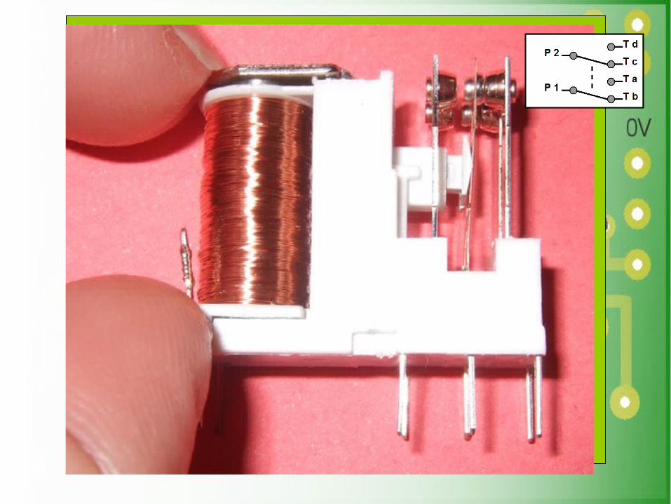
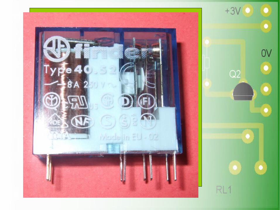
4. Switches and Relay
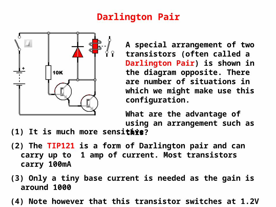
Darlington Pair
A special arrangement of two transistors (often called a Darlington Pair) is shown in the diagram opposite. There are number of situations in which we might make use this configuration.
What are the advantage of using an arrangement such as this?(1) It is much more sensitive
(2) The TIP121 is a form of Darlington pair and can carry up to 1 amp of current. Most transistors carry 100mA
(3) Only a tiny base current is needed as the gain is around 1000
(4) Note however that this transistor switches at 1.2V Why?
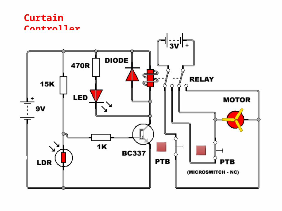
Curtain Controller
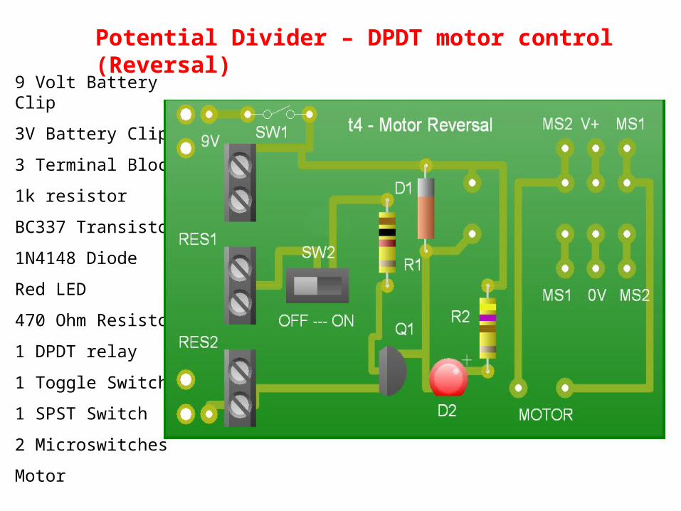
9 Volt Battery Clip
3V Battery Clip
3 Terminal Blocks
1k resistor
BC337 Transistor
1N4148 Diode
Red LED
470 Ohm Resistor
1 DPDT relay
1 Toggle Switch
1 SPST Switch
2 Microswitches
Motor
Potential Divider – DPDT motor control (Reversal)

Potential Divider

Turn 0n Voltage for a Transistor

Variable Resistor
Variable resistors consist of a resistance material with connections at both ends and a wiper which moves along the track as the arm is rotated through 270°.
The track is normally rotary but straight track versions, usually called sliders, are sometimes used.
The further clockwise the wiper is rotated, the larger the resistance.
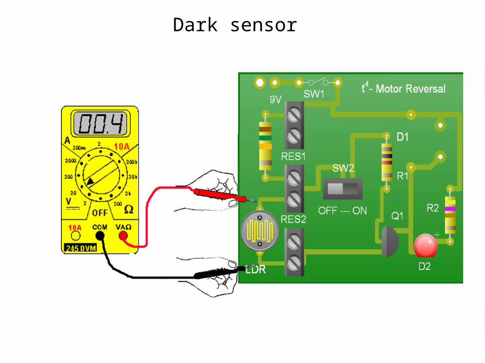
Dark sensor
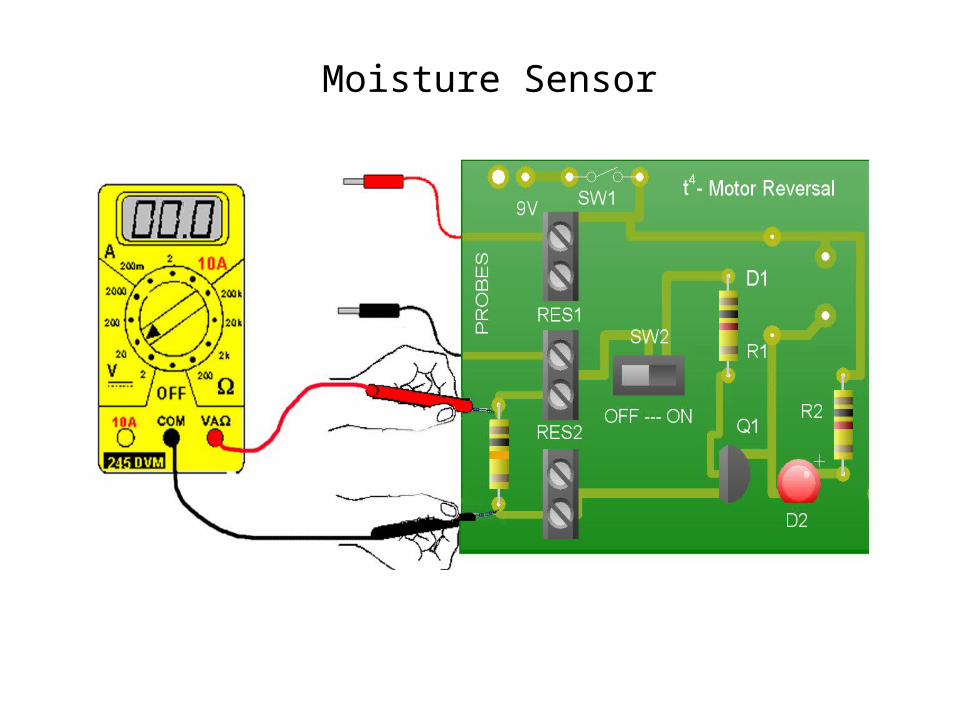
Moisture Sensor

Heat Sensor

Heat Sensor – Hot or Cold

P 1P 2
T b
T a