UCSD Photonics
University of California San DiegoJacobs School of Engineering
Photo: Kevin Walsh, OLR
Range finding using a masked annular folded optic imager
Brett R. Nadler*, Eric J. Tremblay, Jason H. Karp and Joseph E. Ford
Photonic Systems Integration Lab
Thomas BewleyCoordinated Robotics Lab

UCSD PhotonicsRange finding is application drivenModern robotic platforms
• small, mobile, and interact with their environment• require navigation and vision
Design goal• compact ranging and onboard imaging
Requirements• small volume• low power• minimum cost• telephoto imaging• ranging for obstacle avoidance
and observation
Do commercial options exist that satisfy these requirements?2
Packbot Scout (iRobot)
* Coordinated Robotics Lab, robotics.ucsd.edu
iceCube (left) and iHop (right) demonstrate unique maneuverability with small size and low power*
Pointman SUGV(Applied Research Associates)

UCSD Photonics
The optical solutions offer ranging without synchronization with imaging
• Imaging and ranging• aperture/mask• photogrammetry• stereo vision• Moiré• pattern projection/structured illumination
Numerous range finding methods available [ Blais (2003) “Review of 20 years of range sensor development” ]
• Optical ranging• triangulation• time-of-flight• slit scanners• interferometry
Current range finding solutions
3
• Considering range, cost, computational requirements and size eliminates commercial options• However, combination of ranging methods with size appropriate lens would work

UCSD PhotonicsFixed-focus ranging
• Through-the-lens ranging minimizes number of detectors, total volume, power consumption• A fixed-focus imager can use the focal length to determine range
Pattern illumination on three objects
4
• Laser diode source collocated with imager• Detector sends images to computer for visualization and analysis
Deep depth of
focus
Narrow depth of
focus
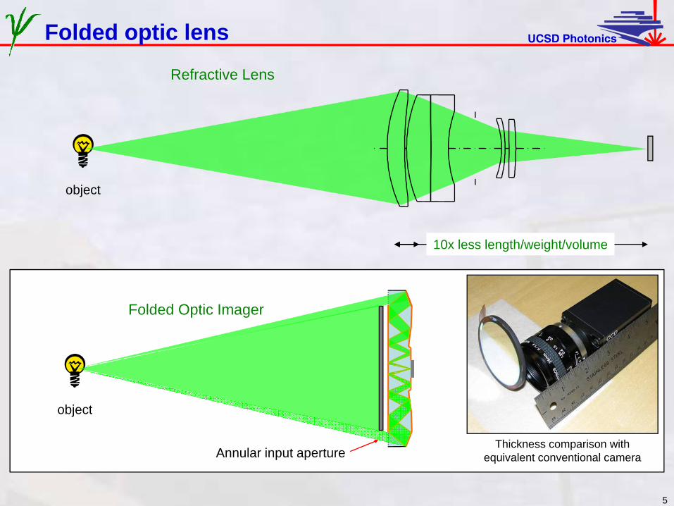
UCSD PhotonicsFolded optic lens
object
Refractive Lens
10x less length/weight/volume
object
Folded Optic Imager
Annular input apertureThickness comparison with
equivalent conventional camera
5

UCSD Photonics
6
Front Positive
Rear Negative
Propagator/Aberration correction
Propagator/Aberration correction
Image
5 mm
Inputaperture
PlaneReflector
0 deg3.3 deg
-3.3 deg
Field Angles
8-Fold Optic Design: Single Sided Structure
Fully-packaged prototypeIncluding USB interface to PC
Imager specifications:• 38 mm effective focal length folded into 5mm track• 60mm diameter, effective circular aperture = 27.3 mm• Image NA = 0.71• Back focal length ~0.5mm• FOV = 0.12 rad• 1280 x 960 pixel• F/#eff= 1.40
6
[Tremblay (2007) “Ultrathin cameras using annular folded optics”]

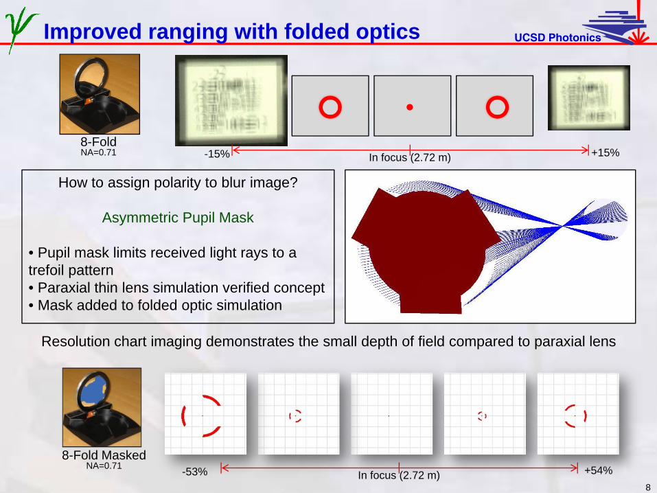
UCSD PhotonicsImproved ranging with folded optics
How to assign polarity to blur image?
Asymmetric Pupil Mask
• Pupil mask limits received light rays to a trefoil pattern• Paraxial thin lens simulation verified concept• Mask added to folded optic simulation
7
• Limited depth of field permits larger blur spots at comparable distances away from focus• Folded optic demonstrates annular blur
8-FoldNA=0.71 In focus (2.72 m) +15%-15%
ConventionalTokina NA=0.5
In focus (2.6 m) +15%-15%
UCSD PhotonicsImproved ranging with folded optics
8
Resolution chart imaging demonstrates the small depth of field compared to paraxial lens
8-Fold MaskedNA=0.71
In focus (2.72 m) +54%-53%
8-FoldNA=0.71 In focus (2.72 m) +15%-15%
How to assign polarity to blur image?
Asymmetric Pupil Mask
• Pupil mask limits received light rays to a trefoil pattern• Paraxial thin lens simulation verified concept• Mask added to folded optic simulation

UCSD PhotonicsImage processing steps
9
Raw image
RGB filter, for red intensity and hue
Mean filter, softens image by averaging with 10x10 pixel windows
Center of gravity calculated for each blob
Radius calculation:1. CGs are vertices of equilateral
triangle2. Measure the pixel distance
between two CGsCanny edge detector with low/high thresholds at 5/20

UCSD Photonics
illuminated target
Images taken with structured illumination
10
127cm
185cm
Folded Optic Imager
273cm
406cm
598cm

UCSD PhotonicsCalibration curve and output comparison
11
Experimental Range Data and Simulation DataR
adiu
s (m
m) o
f blu
r circ
le
Range (m)
Experimental curve matches closely with the numerical simulation performed in Zemax

UCSD PhotonicsCalibration curve and output comparison
12
Numerical vs. Experimental Radii of Blur CircleE
xper
imen
tal R
ange
(m)
Simulation Range (m)
Further examination shows deviation of experimental data at large distances

UCSD Photonics
Conclusions
• The design goal was met. •integrated vision and ranging•low power and volume
• Experimental results followed theory except for drift at long ranges (10m+)
• Provides larger blur diameters between lens and focal length than paraxial thin lens
Conclusion and future directions
Future directions
• Variable focus lens• Pupil mask modifications
•Laser wavelength filtering• Alternative asymmetric mask shapes
• Pattern arrays• Concentric imagers
13
Limitations
Real world demonstrations with ambient light caused anomalies in image processing
Range finding most accurate between minimum observable range and focal length

UCSD Photonics
Thank You,[email protected]
14
Photonic Systems Integration Laboratory, psilab.ucsd.eduUniversity of California San Diego