111
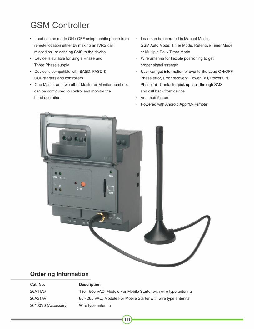
GSM Controller
• Load can be made ON / OFF using mobile phone from
remote location either by making an IVRS call,
missed call or sending SMS to the device
• Device is suitable for Single Phase and
Three Phase supply
• Device is compatible with SASD, FASD &
DOL starters and controllers
• One Master and two other Master or Monitor numbers
can be configured to control and monitor the
Load operation
• Load can be operated in Manual Mode,
GSM Auto Mode, Timer Mode, Retentive Timer Mode
or Multiple Daily Timer Mode
• Wire antenna for flexible positioning to get
proper signal strength
• User can get information of events like Load ON/OFF,
Phase error, Error recovery, Power Fail, Power ON,
Phase fail, Contactor pick up fault through SMS
and call back from device
• Anti-theft feature
• Powered with Android App “M-Remote”
Ordering Information
Cat. No. Description
26A11AV 180 - 500 VAC, Module For Mobile Starter with wire type antenna
26A21AV 85 - 265 VAC, Module For Mobile Starter with wire type antenna
26100V0 (Accessory) Wire type antenna

TERMINAL TORQUE & CAPACITY
Note: It is strongly recommended to use
Single Phasing Protection Device (SPPR)
for Motor Protection with GSM Controller
CONNECTION DIAGRAMR phase / L
Toggle Switch
Stop Switch
Start Switch
15
16
A1
A2
NO-H
Supply F/B to I1 of GSM
Starter F/B to I2 of GSM
For Star Delta Starter, take I2 feedback from A1 of Delta contactor.
HoldingContactor
B phase / N
GSMNO
GSMNC
25
28
SPPR
(To COM of GSM)
Note: This Product is only available for Sale Outside India
MOUNTING DIMENSIONS (mm)
112
GSM Controller
Parameters
26A11AVCat. No.
Frequency
Power Consumption (Max.)
180V AC to 500V AC (For Single Phase : Connect Live to R or Y & Neutral to B & COM terminal of Controller)
50-60 Hz
10 VA
Terminal 15 & 16 – NC ,Terminal 25 & 28 – NO, 5A @ 250V AC / 30V DC (Res)
45 Sec
Contact Ratings
Initialisation Time
Supply Voltage ( )
FUNCTIONAL CHARACTERISTICS :
LED Indications
LED INDICATION
ON (Green) ONBlinking @ 500 m Sec
CFG (Red)
N/W (Green) Flash every 800 m sec
Flash every 3 sec
I1 & I2 (Yellow)
Both ON Both OFF
Tx/Rx (Green)
Blinking @ 500 m Sec
Both blinking
Operating Temperature
Storage Temperature0° C o + 0° C t 6 20° C to +70° C-
Enclosure F ame Re a t 4 0l t rdan UL9 -V
Dimension (W x H x D) (in mm) 7 02 X 9 .5 X 65
220 g approx.Weight (unpacked)
Mounting DIN rail / Base
Humidity (Non Condensing) 95% (Rh)
Degree of Protection 2 f r a P n reIP 0 o Termin ls, I 30 for E closu
CertificationRoHS Compliant
GSM Modem Quad band 850MHz,900MHz / 1800MHz,1900MHz
Randomly Blinking
I1 Blinking @ 500 m Sec
Flash every 400 m Sec
DEVICE STATUS
GSM modem in factory default mode
Master number configured.
GSM modem in configuration mode
Not registered with N/W Registered with N/W
Starter ON Starter OFF
Power fail indication till super capacitor back up
Communication between CPU and Modem
Phase fail
SIM card not detected
Environmental Compliance Cold Heat IEC 60068-2-1Dry Heat IEC 60068-2-2Vibration IEC 60068-2-6Repetitive Shock IEC 60068-2-27Non-Repetitive Shock IEC 60068-2-27
EMI / EMCHarmonic Current Emissions IEC 61000-3-2ESD IEC 61000-4-2Radiated Susceptibility IEC 61000-4-3Electrical Fast Transients IEC 61000-4-4Surges IEC 61000-4-5Conducted Susceptibility IEC 61000-4-6Voltage Dips & Interruptions (AC) IEC 61000-4-11Voltage Dips & Interruptions (DC) IEC 61000-4-29Conducted Emission CISPR 14-1Radiated Emission CISPR 14-1
Ø 3.5
AWG
0.54 N.m (6 Lb.in)
2 1 x 2.5 mm Solid Wire/Stranded
1 x 24 to 12

113
GSM Controller
General SMS Queries : (To be sent only from Master number to Device number)
Configuration Steps
SMS QUERY ACTION
When call is made to device, recorded voice guide the User to operate the Load. (Factory set)
Missed Call
If Master number disables Voice call (IVRS) feature by 41<space>0 query, then User can operate the Load by Missed Call mode. When User call device, then device cut the call after 3-4 rings to make Load ON and cut the call after 5-6 rings to make Load OFF.
11<space>0 After receiving SMS 11 0, device turns ON the Load.
Step 6 : Call the device number, call will be disconnected after 1 to 2 rings.
Step 7 : After call gets disconnected, ON LED stops blinking & becomes permanently ON.CFG LED turns OFF. This will indicate that, master number has been configured in thedevice. User will receive SMS of “ROLE : MASTER”.
Step 8 : To configure other Master numbers if required, send query 55<Space>Mobile no.1<Space>Mobile no.2 from the master number.
Step 9 : After installing device for the first time, set the device clock by sending query “16”. User will receive SMS,"TIME : SET , TM : 14.10,01/12/16".
Step 10 : If device is connected to single phase supply, then configure device for single phasesupply by sending query 18<space>1. User will receive SMS - SUPPLY – 1 PHASE
Step 11 : If device is connected in Semi Automatic Star Delta starter then configure the devicein SASD system by sending query 77<space>0.User will receive SMS – PANEL : SASD.
Step 12 : User should refer the “General SMS Queries” for functional details of the device.
*Note : In factory default, ON LED will continuously remain ON for aprox. 10 sec till supercapacitor charging and then start blinking.
Step 1:Insert SIM card in the slot provided and connect Antenna.
Step 2:Power on device & wait for 50 sec. ON (Green) LED will startblinking*, indicating that device is in factory default mode.After every power on, device will take 50 to 80 sec forinitialization during which user should wait.
Step 3:Ensure that NW (Network) LED is flashing after every 3 sec. It means device is registered with inserted SIM N/W. If NWLED is blinking faster, it means that the device is not registeredwith SIM NW & hence not ready for operation.
Step 4:Press the CFG (Configuration) key on the device till CFG(RED) LED starts blinking. The device goes in theconfiguration mode to configure the master number in thedevice.
Step 5:CFG LED will blink for 3 min, user should configure the masternumber within this time.
Step 6:Call the device number, call will be disconnected after 1 to 2rings.
Voice Call (IVRS)
Functional Queries
00 After receiving SMS 00, device turns OFF the Load.
After receiving this query, Load is turned ON in timer mode till specified end time. Here HH indicates Hour and MM indicates Minutes. E.g. after receiving 11 00 30 query, Load is turned ON till next 30 minutes. In Timer mode, error and power fail duration is not compensated. Load can be operated in timer mode from min 1 min to max 23.59 Hrs.
11<space>HH<space>MM
(Timer Mode)
21<space>HH<space>MM
(Retentive Timer Mode)
After receiving this query, Load is turned ON in Ret. timer mode for set time. Here HH indicates Hour and MM indicates Minutes. E.g. after receiving 21 00 30 query, Load is turned ON for 30 minutes. In Ret. Timer mode, error and power fail duration is compensated. Load can be operated in Ret. Timer mode from min 1 min to max 23.59 Hrs.
22<space>HH.MM<space> HH.MM(Daily Timer Mode)
After receiving this query, device make Load ON and OFF as per set time on daily basis. Here HH indicates Hour and MM indicates Minutes. Load ON and OFF time can be set in 24 Hrs format only. Master number can set min 1 and max 4 daily timers. E.g. If master send query 22 10.30 12,then device daily make Load ON at 10.30AM and OFF at 12PM. If master want to operate 4 daily timers, then send query e.g. 22 9 11.30,11.35 13.45,15 16,17.30 19 After receiving this query,Load turns ON and OFF 4 times a day as per set time. There should be 1 min difference between 2 daily timers.
22 After receiving this query from Master number, daily timer settings are disabled.
23(Hour Meter)
After receiving this query, User get to know, for how many hours Load was ON since installation of the device. Only Master number can reset hour meter to zero by sending query 23<space>0.
41<space>0 or 10 – To disable Voice call(IVRS) and enable Missed call mode1 – To enable Voice call(IVRS) and disable Missed call mode (Factory Set)
42<space>0 or 1 0 – To disable Call back from device (Factory Set) / 1 – To enable Call back from device
43<space>0 or 1 0 – To stop receiving Event SMS from Device. / 1 – To start receiving Event SMS from Device. (Factory Set)
66<space>1 To make Load ON in Auto mode.66<space>0 To make Load OFF only if it is ON in Auto mode.
97
98
99
INFO
To know System settings.
To know daily timer settings.
To know current status of Load.To know all frequently used queries.
15<space>0, balance codeA
Configuration Queries
After receiving this query , User get balance information. Balance code need to be correctly set.E.g. 15 0,*121# (*12# is balance code. It changes as per Service provider)
15<space>1, balance codeA After receiving this query , User get balance information automatically after every 16 to 20th SMS.
16 After receiving this query, Device time will be set as per time of Master’s SIM Network.
17 To know configured master & other master / monitor numbers.
18<space>1 or 3 1 -To configure with 1 PH Supply / 3 - To configure with 3 PH Supply (Factory Set).
44<space>xxxx (xxxx indicates last four digit of previous master number)
To replace the previous master number with new one, send query 44<space>xxxx from a new number which is to be configured as Master. (Note: 1.Before sending this query first press configuration key on device till CFG LED starts blinking 2. After this query, previously stored other master/monitor numbers will be deleted & new numbers need to be configured)
50<space>X(X is ON delay which ranges from 0 to 5 minutes)
Master number can configure ON delay in the Device by sending query 50.To set ON delay of 30 sec, Master number should send query 50<space>0,similarly 50<space>1 for 1 minute ON delay and upto 5 minutes in multiple of 1 minutes. The default setting of ON delay in the device is 30 sec. ON delay is applied whenever Load is to be turned ON after error or power fail or command off.
55<space>First number<space>Second number
By sending this query Master number can configure 2 other Master numbers with device. Other Master numbers can also turn ON and OFF Load by call or SMS. OR Master number can configure 2 Monitor numbers by suffixing letter M to mobile numbers in 55 query. (e.g 55<space>xxxxxxxxxxM). Monitor numbers can only receive event SMS from device. To change the numbers, Master can resend 55 query with new numbers which are to be configured. (Note: While entering numbers, ensure that correct number is entered. Numbers can be verified by sending 17 query).
55 To remove other master /monitor numbers, send only 55 query to device from Master number.
77<space>0 or 1 0 -To configure with SASD starter / 1 - To configure with DOL/FASD starter (Factory Set).
12
Troubleshooting / Security Queries
To check network range
To know IMEI number and F/W version of the device.13
NOTE : 1) Other Master numbers have access to call and queries 00, 11, 12, 13,17,21,23,44, 66, 97,98, 99 and info.2) Monitor numbers have access to queries 12, 13,17,21,23,44, 97,98,99 and info.


![DATA SHEET AAT4687-1: Over-Voltage Protection Switch · DATA SHEET • AAT4687-1: OVER-VOLTAGE PROTECTION SWITCH Skyworks Solutions, Inc. • Phone [781] 376-3000 • Fax [781] 376-3100](https://static.cupdf.com/doc/110x72/5b4845d17f8b9aa4148d62f8/data-sheet-aat4687-1-over-voltage-protection-data-sheet-aat4687-1-over-voltage.jpg)