HAL Id: hal-02324280https://hal-enac.archives-ouvertes.fr/hal-02324280
Submitted on 22 Oct 2019
HAL is a multi-disciplinary open accessarchive for the deposit and dissemination of sci-entific research documents, whether they are pub-lished or not. The documents may come fromteaching and research institutions in France orabroad, or from public or private research centers.
L’archive ouverte pluridisciplinaire HAL, estdestinée au dépôt et à la diffusion de documentsscientifiques de niveau recherche, publiés ou non,émanant des établissements d’enseignement et derecherche français ou étrangers, des laboratoirespublics ou privés.
Processed 5G Signals Mathematical Models forPositioning considering a Non-Constant Propagation
ChannelAnne-Marie Tobie, Axel Javier Garcia Peña, Paul Thevenon, Marion Aubault
To cite this version:Anne-Marie Tobie, Axel Javier Garcia Peña, Paul Thevenon, Marion Aubault. Processed 5G SignalsMathematical Models for Positioning considering a Non-Constant Propagation Channel. VTC 2019-Fall 2019 IEEE 90th Vehicular Technology Conference, Sep 2019, Honolulu, United States. �hal-02324280�
Processed 5G Signals Mathematical Models for
Positioning considering a Non-Constant Propagation
Channel
Anne-Marie TOBIE
TéSA (ENAC) Toulouse, FRANCE
Axel GARCIA-PENA
ENAC Toulouse, FRANCE
Paul THEVENON
ENAC Toulouse, FRANCE
Marion AUBAULT
CNES Toulouse, FRANCE
Abstract— The objective of this paper is to determine the
ranging performance of the upcoming fifth generation (5G)
signal. In order to do so, it is required to define 5G correlator
outputs mathematical models. 5G systems will use OFDM
(Orthogonal Frequency Division Multiplexing) signals; in the
literature, mathematical models of OFDM signals are
developed at the different receiver signal processing stages.
These models assumed that the propagation channel is
constant over an OFDM symbol; nevertheless, an in-depth
study of QuaDRiGa, a 5G compliant propagation channel
simulator, invalidates this hypothesis. Therefore, in this paper,
mathematical models are developed that take into account the
channel evolution. The focus is given on correlator outputs and
results are applied to the computation of 5G based pseudo
range accuracy.
Keywords—5G systems, CIR, correlator outputs, DLL, GNSS,
OFDM, propagation channel, QuaDRiGa
INTRODUCTION I.
Over the past few years, the need for positioning, and
thus the number of positioning services in general, has been
in constant growth. This need for positioning has been
increasingly focused on constraint environments, such as
urban or indoor environments, where GNSS (Global
Navigation Satellite System) is known to have significant
limitations: multipath as well as the lack of Line-of-Sight
satellite visibility degrades the GNSS positioning solution
and makes it unsuitable for some urban or indoor
applications. In order to improve the GNSS positioning
performance in constrained environments, many solutions
are already available: hybridization with additional sensors
or the use of signals of opportunity for example, [1], [2], [3],
[5]. Concerning signals of opportunity, mobile
communication signals, such as the 4G LTE ([1]) or 5G, are
naturally envisioned. Indeed, a significant number of users
are expected to be “connected-users” and 5G systems offers
promising opportunities.
5G technology is being currently standardized and its
positioning performance, as well as a potential generic
receiver scheme to conduct positioning operations, is still
under analysis. In order to develop such a positioning
module, it is of the utmost importance to correctly
characterize the mathematical models of the processed 5G
signals at each stage of the receiver: the knowledge of these
mathematical models will allow for the development of
signal processing algorithms optimally adapted to the 5G
received signal.
Previous efforts have been made to provide the
mathematical model of the 5G received signal at the
different receiver signal processing stages. For example,
taking into account that, as defined in 3GPP standard, 5G
systems use Orthogonal Frequency Division Multiplexing
(OFDM) signals, the OFDM signal-type correlator output
mathematical model and acquisition techniques derived in
[2], [3], [4], [5], [6] could be applicable to 5G signals.
Moreover, in [6], tracking and acquisition techniques were
proposed, analyzed and tested based on the correlator output
mathematical model presented in [5]. However, this model
was derived by assuming a constant propagation channel
over the duration of the correlation (which is performed
over one OFDM symbol). Nevertheless, an analysis
conducted on the Channel Impulse Response (CIR) of a
representative 5G signals propagation channel, QuaDRiGa
[7], has shown that the CIR cannot be considered as
constant over the duration of the correlation. Moreover, this
analysis has also shown that the expected 5G signal
processing behavior is different between a time-evolving
CIR and a constant one over the duration of an OFDM
symbol.
This article aims thus at extending the DVB-T signals
ranging module (Delay Lock Loop – DLL) presented in [5]
for constant CIR propagation channels to a 5G signals
ranging module (DLL) for time-evolving CIR propagation
channels. The key point of this derivation consists in
developing an evolved mathematical model for 5G signals
correlator outputs which takes into account the CIR
evolution over the duration of one OFDM symbol.
In order to meet this objective, the article is organized in
8 sections in addition to the introduction and conclusion.
First, 5G signals structure and a generic communication
chain scheme are presented. Second, the architecture of the
envisioned DLL based on [6] is presented for an AWGN.
Third, the correlation operation in AWGN is presented.
Fourth, the correlator output operation is defined, and its
mathematical model is developed and validated for a CIR
constant over the duration of the correlation. Fifth, the
model for a time-evolving CIR is derived. Sixth, the
correlator output mathematical model is developed and
validated for a time-evolving CIR. Seventh, the 5G signals
compliant propagation channel being adopted, QuaDRiGa,

[7] is presented. Finally, the code delay tracking error of the
derived 5G signal tracking module is provided for an
AWGN channel and for the QuaDRiGa propagation channel
model.
5G SIGNAL PRESENTATION II.
5G systems use OFDM signals. The process to
generate an OFDM signal is illustrated in Fig.1. The
symbols {𝑑0𝑘 , … , 𝑑𝑁−1
𝑘 } are first modulated by applying an
inverse Fast Fourier Transform (IFFT). Then the Cycle
Prefix (CP) is added creating an OFDM time symbol. At
this point the complex envelope signal model (consisting in
one OFDM time symbol) can be expressed as in (1).
𝑠𝑘[𝑛] = ∑ 𝑑𝑝𝑘𝑒
𝑖2𝜋𝑝𝑛
𝑁𝐹𝐹𝑇𝑁𝐹𝐹𝑇−1𝑝=0 − 𝑁𝐶𝑃 ≤ 𝑛 ≤ 𝑁𝐹𝐹𝑇 − 1 (1)
Where 𝑁𝐶𝑃 is the number of Cycle Prefix samples,
𝑁𝐹𝐹𝑇 is the size of the FFT window, 𝑝 is the subcarrier, 𝑛
indicates the 𝑛𝑡ℎ discrete time epoch, 𝑘 indicates the 𝑘𝑡ℎ
OFDM symbol, 𝑑𝑝𝑘 is the 𝑘𝑡ℎ modulated symbol carried by
the 𝑝𝑡ℎ subcarrier.
The OFDM signal is then transmitted through the
propagation channel, which CIR mathematical model is
usually expressed as 𝛼𝑘(𝑡) . The received signal
mathematical model can then be expressed by the
convolution between the incoming signal and the previously
defined CIR propagation channel, where 𝑟𝑘(𝑡) expresses
the noiseless received signal before the ADC/AGC.
𝑟𝑘(𝑡) = 𝑠𝑘(𝑡) ∗ 𝛼𝑘(𝑡) (2) The CP is removed from this received signal, and
finally, the signal is demodulated using a Fast Fourier
Transform (FFT).
ENVISIONED 5G RANGING MODULE III.
The main objective of this article is to design a 5G signal ranging module performing the time-of-arrival estimation thanks to a Delay-Lock Loop (DLL). The aim of the ranging module is thus to estimate the transmitted signal propagation
delay 𝜏 between the 5G emitter and receiver. The selected generic DLL diagram block scheme is illustrated in Fig2, [1], [6]; this scheme is adapted for an AWGN channel. The tracking step provided by Fig.2 is preceded by an acquisition step. The acquisition process consists in using algorithms such as the Van de Beek algorithm, [9], followed by the matching pursuit, presented in [6], to achieve a rough time and frequency synchronization with the incoming signal. The tracking (fine estimation) of the rough estimated propagation delays obtained during the acquisition phase is then conducted by the DLL.
The DLL makes use of correlation between the incoming
signal, 𝑟𝑘[𝑛]. and a local replica, 𝐿𝑅, performed on the pilot
symbols that are present in the 5G Synchronization Signals.
The CIR mathematical model of an AWGN channel can be
expressed as 𝛼𝑘(𝑡) = 𝛼𝛿(𝑡 − 𝜏), where 𝛼 is the complex
amplitude of the AWGN propagation channel and 𝜏 is the
propagation time delay, The noiseless received signal
mathematical model can then be derived from the
convolution between the incoming signal and this CIR
propagation channel as: 𝑟𝑘(𝑡) = 𝑠𝑘(𝑡) ∗ 𝛼𝑘(𝑡). the digital
version, 𝑟𝑘[𝑛], is provided in (3).
𝑟𝑘[𝑛] = 𝛼 ∑ 𝑑𝑝𝑘𝑒
𝑖2𝜋𝑝(𝑛−𝜏𝑛)
𝑁𝐹𝐹𝑇𝑁𝐹𝐹𝑇−1𝑝=0 (3)
The propagation delay estimated by the DLL is denoted
as �̂�. The correlation between the incoming signal and the local replica is computed at three points spaced by a distance 𝑑 called the correlator spacing (d=4 samples in the following).
�̂� −𝑑
2 for the early correlator output: 𝑅𝐸(휀𝜏)
�̂� for the prompt correlator output: 𝑅𝑃(휀𝜏)
�̂� +𝑑
2 for the late correlator output: 𝑅𝐿(휀𝜏)
Where 휀𝜏 = 𝜏 − �̂� is defined as the propagation delay estimation error. The discriminator output is then computed thanks to these 3 correlator outputs. The discriminator chosen is the Early Minus Late Power (EMLP) defined in (4) and studied in [6]:
𝐷𝐸𝑀𝐿𝑃𝑛𝑜𝑟𝑚(휀𝜏) =
|𝑅𝐸( 𝜏)|2−|𝑅𝐿( 𝜏)|
2
𝐾𝑛𝑜𝑟𝑚|𝑅𝑃( 𝜏)|2 (4)
This discriminator is normalized by 𝐾𝑛𝑜𝑟𝑚 such that
𝐷𝐸𝑀𝐿𝑃𝑛𝑜𝑟𝑚(휀𝜏) = 휀𝜏 for 휀𝜏 close to 0, its expression is derived in
[6]. The discriminator output is then filtered by a low-pass
filter. The new delay estimate is then generated using a DCO
(Digitally Controlled Oscillator) and new Early, Prompt and
Late correlator outputs are computed. Finally, the correlation
operation is the basis of the ranging module as shown in this
section. Therefore, the correct mathematical modelling of its
output is mandatory in order to develop a ranging module
adapted to the targeted propagation channel. This modelling
will be the aim of the next sections.
CORRELATION OPERATION DEFINITION IV.
The correlation operation can be defined for an OFDM
symbol from its direct time-domain expression or from the
equivalent frequency-domain expression. The schemes of
the time-domain and frequency-domain correlation
operations are given in Fig.3. In the time domain, the
incoming signal is multiplied with the local replica, and then
accumulated (integration and dump) to get the correlation
result. In the frequency domain, the incoming signal is first
demodulated thanks to a FFT operation and then it is
multiplied with the FFT of the local replica. Then, an iFFT
is performed in order to come back to the time domain. Only
the first term of the iFFT output is considered and
denominated as “IFFT in 0” in Fig. 3.
Additionally, note that the received signal is also
demodulated by applying a FFT as presented in (5) when 𝜏
Fig. 1 – OFDM transmission and reception chain
Fig. 2 DLL architecture

is accurately estimated.
�̃�𝑝′𝑘 = 𝐹𝐹𝑇(𝑟𝑘[𝑛])[𝑝′] = ∑ 𝑟𝑘[𝑛]
𝑁𝐹𝐹𝑇−1𝑛=0 𝑒
−𝑖2𝜋𝑛𝑝′
𝑁𝐹𝐹𝑇 (5)
With such expressions it is easier to tune the shifting
process in the frequency domain. Therefore, the correlator
output mathematical model is derived from this
implementation, i.e. the FFT in the frequency domain.
CORRELATOR OUTPUT MATHEMATICAL MODEL FOR A V.
CONSTANT CIR OVER ONE OFDM SYMBOL
In this section, the correlator output mathematical
model is derived for a constant CIR over one OFDM
symbol. A more general propagation channel CIR
mathematical model is now expressed as follow 𝛼𝑘(𝑡) =∑ 𝛼𝑙
𝑘𝛿(𝑡 − 𝜏𝑙)𝐿−1𝑙=0 . Where 𝛼𝑙
𝑘 is the complex amplitude of
the 𝑘𝑡ℎ OFDM time symbol and the 𝑙𝑡ℎ path, 𝜏𝑙 is the delay
of the 𝑙𝑡ℎ multipath, 𝐿 is the total number of multipath and 𝑙 is the multipath id. The noiseless received digital signal
mathematical model 𝑟𝑘[𝑛] is provided in (6).
𝑟𝑘[𝑛] = ∑ 𝛼𝑙𝑘 ∑ 𝑑𝑝
𝑘𝑒𝑖2𝜋𝑝(𝑛−�̃�𝑙)
𝑁𝐹𝐹𝑇𝑁𝐹𝐹𝑇−1𝑝=0
𝐿−1𝑙=0 (6)
Where �̃�𝑙 = 𝜏𝑙/𝑇𝑠 is the normalization of the continuous
parameter by the sampling time 𝑇𝑠. The correlation is performed on pilots only; the general
correlation function expression is defined in [6] as:
𝑅(𝜏) =1
𝑁𝑝∑ �̃�𝑝
𝑘𝐿𝑅𝑝𝑘∗
𝑝∈𝛲 (7)
Where 𝐿𝑅𝑝𝑘 = 𝑝𝑝
𝑘𝑒−2𝑖𝜋𝑝
𝑁𝐹𝐹𝑇𝜏
, 𝑝𝑝𝑘 is the pilot symbol
localized in the 𝑝𝑡ℎ subcarrier on the 𝑘𝑡ℎ symbol. 𝑁𝑝 is the
number of pilot symbols and 𝑃 is the set of pilots. In order to have a generic formula, the set of pilots 𝑃 can be defined as: 𝑃 = 𝛾𝑝′ + 𝛽. Where 𝛾 is the period of repetition of the pilots in the OFDM symbol, 𝑝′ ∈ [0… 𝑁𝑃 − 1] and 𝛽 is the subcarrier index of the first pilot in the symbol. Applying this equation, the final expression of the correlator output is
given in (8) with 휀𝜏𝑙 = (𝜏 − 𝜏𝑙).
𝑅(휀𝜏) =
{
∑
𝛼𝑙𝑘𝑒
𝑖𝜋(2𝛽+𝛾(𝑁𝑝−1))𝜀𝜏𝑙𝑁𝐹𝐹𝑇
𝑁𝐹𝐹𝑇𝑁𝑃
𝐿−1𝑙=0
𝑠𝑖𝑛(𝜋𝛾𝜀𝜏𝑙
𝑁𝑃𝑁𝐹𝐹𝑇
)
𝑠𝑖𝑛(𝜋𝛾𝜀𝜏𝑙𝑁𝐹𝐹𝑇
)휀𝜏𝑙 ≠ 0
1
𝑁𝐹𝐹𝑇∑ 𝛼𝑙
𝑘𝐿−1𝑙=0 휀𝜏𝑙 = 0
(8)
This formula has been validated using 5G pilots. After deep study of the 3GPP standard, [8], only one set of pilots can be used since its scheme is the only one fixed and predictable: the 4-OFDM-symbol-long Synchronization Signal Physical Broadcast CHannel (SSPBCH). The detection and decoding of this block allow the user to achieve downlink synchronization in time/frequency domain and to obtain 5G signal characteristics such as the cell identity or the bandwidth; information required to perform the communication with the network. More specifically, in the following, the focus is done on the second (and fourth) symbol which are composed of 1 Demodulation Reference Signal (DMRS) each 4 subcarriers over 240 subcarriers: 𝑁𝑝 = 60, 𝛾 = 4, 𝛽 = 0 in the following.
MODEL OF A TIME-EVOLVING CIR VI.
The previously developed model assumes that the propagation channel model is constant over the duration of the OFDM symbol. In this section, the consequences of a non-constant propagation channel on the correlation function are presented.
For a time-evolving propagation channel model, the CIR is modelled as:
𝛼𝑘(𝑡, 𝜏) = ∑ 𝛼𝑙𝑘(𝑡, 𝜏)𝐿−1
𝑙=0 (9) The CIR, 𝛼𝑙
𝑘(𝑡, 𝜏), for a given received multipath can be expressed as follow:
𝛼𝑘(𝑡, 𝜏) = ∑ 𝛼𝑙𝑘(𝑡) ∙ 𝛿(𝜏 − 𝜏𝑙)
𝐿−1𝑙=0 (10)
Where 𝜏 is a mathematical variable used for the convolution, 𝑡 is used to model the complex amplitude evolution of each
multipath and 𝛼𝑙𝑘(𝑡) is the evolving complex amplitude of
the 𝑘𝑡ℎ OFDM symbol and the 𝑙𝑡ℎ multipath. Then, the
received signal for the 𝑙𝑡ℎ multipath is calculated as
𝑟(𝑡) = 𝛼𝑙𝑘(𝑡) ∙ 𝛿(𝜏 − 𝜏𝑙) ∗ 𝑠(𝜏)|𝜏=𝑡 = 𝛼𝑙
𝑘(𝑡) ∙ 𝑠(𝑡 − 𝜏𝑙) (11)
Assuming for simplification purposes 𝜏𝑙 = 0 , the received signal Fourier transform is equal to:
𝑅(𝑓) = Α𝑙𝑘(𝑓) ∗ 𝑆(𝑓) (12)
Where Α𝑙𝑘(𝑓) = 𝐹𝑇[𝛼𝑙
𝑘(𝑡)]. If the propagation channel is
constant over the duration of the correlation, 𝛼𝑙𝑘(𝑡) = 𝛼𝑙
𝑘 ,
𝐴𝑙𝑘(𝑓) is a periodic Dirac function. However, if the channel
evolves, 𝛼𝑙𝑘(𝑡) ≠ 𝛼𝑙
𝑘, then the convolution in the frequency domain will create a spectral broadening effect. This spectral broadening implies the loss of the orthogonality between the subcarriers of the OFDM signal. This process is illustrated in Fig. 4.
CORRELATOR OUTPUT MATHEMATICAL MODEL VII.
FOR A NON-CONSTANT CIR OVER ONE OFDM SYMBOL
A. Correlator output mathematical model derivation
The previous correlator output formula, equation (8), was
derived for a propagation channel constant over the duration
of one OFDM symbol. However, in general, 5G signals
propagation channels, cannot be considered as constant, e.g.
QuaDRiGa [7]. In order to develop a correlator output
mathematical model for a time-evolving propagation
channel, the method used for a constant CIR was repeated.
Equations (13) and (14) show the OFDM demodulated
symbol and correlator output mathematical models:
�̃�𝑝𝑘 = 𝑑𝑝
𝑘 + 𝐼𝑛𝑡𝑒𝑟𝑓𝑒𝑟𝑒𝑛𝑐𝑒 (13)
𝑅(휀𝜏) = 𝑅𝑢𝑠𝑒𝑓𝑢𝑙(휀𝜏) + 𝑅𝑖𝑛𝑡𝑒𝑟𝑓(휀𝜏) (14) It must be noted that the useful term, in (14), is different
from the correlator output derived in (8) for a constant channel. Fig.7 can help to understand the impact of the channel on a particular symbol 𝑘. For a constant channel, only one coefficient is considered for each path 𝑙 for each
symbol 𝑘, 𝛼𝑙𝑘 (violet curve); while for an evolving channel,
the impact of the 𝑙-th path on symbol 𝑘 is modelled by the
Fig. 4 Impact of a non-constant propagation channel
Fig.3 – Correlation operation

sum ∑ 𝛼𝑙𝑘(𝑛)
𝑁𝐹𝐹𝑇−1𝑛=0 , the values 𝛼𝑙
𝑘(𝑛) will be constant over
period shorter than the OFDM symbol, and will therefore depend on the chosen CIR sampling rate. In Fig. 7, 3 different sampling rates are illustrated: 10, 20 and 100 CIR sps.
The statistics of the two terms, useful and interference, of the OFDM demodulated symbols as well as the correlator output mathematical model have been analyzed for QuaDRiGa channel (presented in next section). The study proves the negligibility of the interference term with respect to the useful term for this channel. Mathematical demonstrations are not provided here, nevertheless, in Fig.5, an illustration is provided as a justification. Monte-Carlo simulations have been used to assess the amplitude of the useful and interference term of the correlation function for a CIR sampling rate of 100 CIR samples per symbol. On the left is presented the correlation main peak, on the middle the useful (up) and interference (bottom) terms and on the right, the useful and interference terms contributions; which are equal to 100.0048% and 0.0789% of the total correlation function respectively. The contribution is computed using:
|𝑅𝑢𝑠𝑒𝑓𝑢𝑙(휀𝜏)|/|𝑅𝑢𝑠𝑒𝑓𝑢𝑙(휀𝜏) + 𝑅𝑖𝑛𝑡𝑒𝑟𝑓(휀𝜏)| ∙ 100 and
|𝑅𝑖𝑛𝑡𝑒𝑟𝑓(휀𝜏)|/|𝑅𝑢𝑠𝑒𝑓𝑢𝑙(휀𝜏) + 𝑅𝑖𝑛𝑡𝑒𝑟𝑓(휀𝜏)| ∙ 100 respectively;
this permits to understand that the interference term can be destructive, making the useful contribution higher than 100%. Therefore, the final model adopted is limited to
𝑅𝑢𝑠𝑒𝑓𝑢𝑙(휀𝜏) which is defined in (15):
𝑅(휀𝜏) ≈ 𝑅𝑢𝑠𝑒𝑓𝑢𝑙(휀𝜏) =
{
∑
𝐴𝑙𝑘(0)
𝑁𝐹𝐹𝑇𝑁𝑃
𝐿−1𝑙=0 𝑒
𝑖𝜋𝜀𝜏(2𝛽+𝛾(𝑁𝑃−1)
𝑁𝐹𝐹𝑇
𝑠𝑖𝑛(𝜋𝛾𝜀𝜏𝑁𝑃𝑁𝐹𝐹𝑇
)
𝑠𝑖𝑛(
𝜋𝛾𝜀𝜏
𝑁𝐹𝐹𝑇)
휀𝜏 ≠ 0
1
𝑁𝐹𝐹𝑇∑ 𝐴𝑙
𝑘(0)𝐿−1𝑙=0 휀𝜏 = 0
(15)
B. Simplified OFDM correlator output mathematical
models for a non-constant CIR over one OFDM symbol
The correlator output mathematical model contains the
sum 𝐴𝑙𝑘(0) = ∑ 𝛼𝑙
𝑘(𝑛)𝑁𝐹𝐹𝑇−1𝑛=0 which contains the impact of
the evolution of the propagation channel over one symbol
for the lth multipath. The objective of this section is to
simplify this term in order to further simplify the complete
correlator output mathematical model. A potential
application of this simplified model would be the
implementation of a simulator; where the computational
burden is an important factor that must not be forgotten.
In order to simplify 𝐴𝑙𝑘(0), the following hypotheses
are considered:
The sum of the complex amplitudes is split in two
sums, the sum over the modulus and the sum over the
phases:
∑ 𝛼𝑙𝑘(𝑛)
𝑁𝐹𝐹𝑇−1𝑛=0 ≈ (∑ |𝛼𝑙
𝑘(𝑛)|𝑁𝐹𝐹𝑇−1𝑛=0 ) (
∑ 𝑒𝑖𝜃(𝑛)𝑁𝐹𝐹𝑇−1𝑛=0
𝑁𝐹𝐹𝑇) (16)
The sum over the modulus is replaced by the mean
value of the first modulus of the channel impulse
response at the instants of the symbols k and k+1:
∑ |𝛼lk(n)|
NFFT−1n=0 ≈ (|𝛼l
k(0)| + |𝛼lk+1(0)|)NFFT/2 (17)
The phase variation is assumed linear over one symbol
(this assumption has been verified through simulations):
𝜃(𝑛) = 𝜃0𝑘 + 2𝜋𝛿𝑓 ∙ 𝑛. Where 𝜃0
𝑘 is the phase of the
first propagation channel sample applied to the 𝑘𝑡ℎ
OFDM symbol and 𝛿𝑓 = (𝜃0𝑘 − 𝜃0
𝑘+1)/(2𝜋𝑁𝐹𝐹𝑇) is
the normalized Doppler frequency.
This simplification would allow generating only 1 CIR
sample per OFDM symbols instead of 𝑁𝐶𝐼𝑅 CIR samples,
which would greatly reduce the computation time of
propagation channel models, e.g. QuaDRiGa. 𝑁𝐶𝐼𝑅
represents the required number of CIR samples per OFDM
symbol to obtain a propagation channel model equivalent to
a time-continuous channel.
Finally, the channel contribution term can be simplified
as presented in (18).
𝐴𝑙𝑘(0) ≈
|𝛼𝑙𝑘(0)|+|𝛼𝑙
𝑘+1(0)|
2𝑒𝑖(𝜃0+𝜋𝛿𝑓∙(𝑁𝐹𝐹𝑇−1)) 𝑠𝑖𝑛(𝜋𝛿𝑓𝑁𝐹𝐹𝑇)
𝑠𝑖𝑛(𝜋𝛿𝑓) (18)
QUADRIGA: A 5G PROPAGATION CHANNEL VIII.
A. Presentation of the channel
In this article, the propagation channel selected to
validate the correlator output mathematical models
developed in the previous sections is the QuaDRiGa
propagation channel, [7].
QuaDRiGa allows choosing between different scenarios
representative of 5G signals propagation channel models. In
this article, among the proposed configurations
“3GPP_38.901_UMi_LOS” has been selected. This scenario
models typical terrestrial pico-base stations deployed below
rooftop in densely populated urban areas covering carrier
frequencies from 500 MHz to 100GHz. The Line-Of-Sight
(LOS) scenario is a favorable case; the LOS signal is
received with significant higher power than multipath. Pico-
base stations have typically a 4-to-200m-radius-size; thus,
the trajectory simulated is a few meter-long arc of a 100m-
radius circle. Finally, regarding the 5G signal
characteristics, the carrier frequency used is set to 6GHz and
the subcarrier is 15kHz.
B. Time-evolving CIR correlator output validation using
QuaDRiGa
In order to validate the different correlator output
mathematical models presented in section VII, the following
method is applied. First, the correlation is computed over
2000 symbols for four cases:
1. the correlation operation using a sampling interval of
100 CIR samples per OFDM symbols (the reference),
2. the correlation operation using a sampling interval of 10
CIR samples per OFDM symbols,
3. the correlation using a sampling interval of 10 CIR
samples per OFDM symbols using (15), and
4. the correlation using (18), using only 1 CIR sample per
OFDM symbol.
Fig 5. Negligibility of the interference term
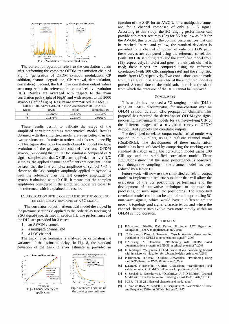
The correlation operation refers to the correlation obtain
after performing the complete OFDM transmission chain of
Fig. 1 (generation of OFDM symbol, modulation, CP
addition, channel degradation, CP removal, demodulation,
correlation). Second, the last three correlation output values
are compared to the reference in terms of relative evolution
(RE). Results are averaged with respect to the main
correlation peak (right of Fig.6) and with respect to the 2000
symbols (left of Fig.6). Results are summarized in Table. 1 TABLE 1 – RELATIVE EVOLUTION MEAN AND STANDARD DEVIATION
Model 10CIR Initial Simplification
μ 0.1267% 0.1379% 0.1016%
σ 0.1178% 0.1237% 0.0866%
These results permit to validate the usage of the
simplified correlator outputs mathematical model. Results
obtained with the simplified model are even better than the
two previous one. In order to understand this result, see Fig
7. This figure illustrates the method used to model the time
evolution of the propagation channel over one OFDM
symbol. Supposing that an OFDM symbol is composed of N
signal samples and that X CIRs are applied, then over N/X
samples, the applied channel coefficients are constant. It can
be seen that the first complex amplitude of symbol k+1 is
closer to the last complex amplitude applied to symbol k
with the reference than the last complex amplitude of
symbol k obtained with 10 CIR. It means that the complex
amplitudes considered in the simplified model are closer to
the reference, which explained the results.
APPLICATION OF THE CORRELATOR OUTPUT MODEL TO IX.
THE CODE DELAY TRACKING OF A 5G SIGNAL
The correlator output mathematical model developed in
the previous sections is applied to the code delay tracking of
a 5G signal-type, defined in section III. The performances of
the DLL are provided for 3 cases:
1. an AWGN channel, 2. a multipath channel and 3. a LOS channel. The tracking performance is analyzed by calculating the
variance of the estimated delay. In Fig. 8, the standard
deviation of the tracking error estimate is provided in
function of the SNR for an AWGN, for a multipath channel
and for a channel composed of only a LOS signal.
According to this study, the 5G ranging performance can
provide sub-meter accuracy (3σ) for SNR as low as 0dB for
the AWGN; this provides the optimal performances that can
be reached. In red and yellow, the standard deviation is
provided for a channel composed of only one LOS path;
these curves are computed using the reference correlation
(with 100 CIR sampling rate) and the simplified model from
(18) respectively. In violet and green, a multipath channel is
used; these curves are computed using the reference
correlation (with 100 CIR sampling rate) and the simplified
model from (18) respectively. Two conclusions can be made
from this figure. First, the validity of the simplified model is
proved. Second, due to the multipath, there is a threshold
from which the precision of the DLL cannot be improved.
CONCLUSION
This article has proposed a 5G ranging module (DLL),
using an EMPL discriminator, for non-constant over an
OFDM symbol duration CIR propagation channels. This
proposal has required the derivation of OFDM-type signal
processing mathematical models for a time-evolving CIR of
the different stages of a navigation receiver: OFDM
demodulated symbols and correlator outputs.
The developed correlator output mathematical model was
applied to a 5G pilots, using a realistic channel model
(QuaDRiGa). The development of these mathematical
models has been validated by comparing the tracking error
standard deviation using the correlation model using 100
CIR sps and the simplified correlation model. These
simulations show that the same performance is observed,
even though the sampling of the channel model has been
reduced by a factor 100.
Future work will now use the simplified correlator output
model to implement a realistic simulator that will allow the
evaluation of the 5G positioning performance and the
development of innovative techniques to optimize the
processing of such signal for positioning. The simplified
correlator model could also be applied on the promising 5G
mm-wave signals, which would have a different emitter
network topology and signal characteristics, and where the
channel characteristics evolve even more rapidly within an
OFDM symbol duration.
REFERENCES
[1] K.Shamaei, J.Khalife, Z.M. Kassas, “Exploiting LTE Signals for Navigation: Theory to Implementation”, 2018
[2] C.Mensing, S.Plass, A.Dammann, “Synchronization algorithms for positioning with OFDM communciations signals”, 2007
[3] C.Mensing, A. Dammann, “Positioning with OFDM based communications systems and GNSS in critical scenarios”, 2008
[4] E.Staudinger, “A generic OFDM based TDoA positioning testbed with interference mitigation for subsample delay estimation”, 2011
[5] P.Thevenon, D.Serant, O.Julien, C.Macabiau, “Positioning using mobile TV based on DVB-SH standard”, 2014
[6] D.Serant, P.Thevenon, O.Julien, C.Macabiau, “Development and validation of an OFDM/DVB-T sensor for positioning”, 2010
[7] S. Jaeckel, L. Raschkowski, “QuaDRiGa: A 3-D Multicell Channel Model with Time Evolution for Enabling Virtual Field Trials," 2014.
[8] 3GPP, "TS 38.211 Physical channels and modulation".
[9] J-J Van de Beek, M. sandell, P.O. Börjesson, “ML estimation of Time and Frequency Offset in OFDM Systems”, 1997
Fig. 6 Validation of the simplified model
Fig.7 Channel coefficient
application
Fig. 8 Standard deviation of the tracking error estimate