PROCESS AND QUALITY CHARACTERIZATION FOR
ULTRASONIC WELDING OF LITHIUM-ION BATTERIES
by
Seungjae Lee
A dissertation submitted in partial fulfillment
of the requirements for the degree of
Doctor of Philosophy
(Mechanical Engineering)
in the University of Michigan
2013
Doctoral Committee:
Professor S. Jack Hu, Co-Chair
Professor Elijah Kannatey-Asibu Jr., Co-Chair
Professor John Edmond Allison
Wayne W. Cai, General Motors
Assistant Research Scientist Tae Hyung Kim

Seungjae Lee 2013

ii
DEDICATION
Dedicated to my family
for their love, guidance, and support

iii
ACKNOWLEDGEMENTS
I would like to express my sincere thanks to my advisors, committee members,
colleagues, family and many others for their guidance, help and support. Without them, I
would never have been able to finish this dissertation.
First and foremost, my deepest gratitude goes to my advisor, Professor S. Jack Hu
for his countless advices and patient encouragement. He shared with me his brilliant
insight and great vision on my research. He showed me an example of how to be a good
researcher but at the same time a great leader and personnel. I have been amazingly
fortunate to have an advisor who could provide me such a wonderful guidance to this
long journey.
My deepest thank also goes to my co-advisor Professor Elijah Kannatey-Asibu Jr.
for his invaluable comments and guidance on my thesis. He shared with me his vast
knowledge and experience on my research area and provided me tremendous help to
finish my dissertation thesis.
I would like to extend my sincere gratitude to the committee members including
my, Professor John Allison, Dr. Tae Kim, and Dr. Wayne Cai for their support, guidance,
and invaluable comments during my study. I also want to thank Dr. Cai and General
Motors for the financial support and internship opportunities.
I thank all the Hu Lab members as well as many other friends and colleagues that
I have worked with for their unconditional support and friendship. It has been a great
pleasure to work with you all.

iv
More importantly, none of this would have been possible without the love and
support from my family. My parents and parents-in-law have been a constant source of
love, concern, support and strength all these years. I want to express my deepest thanks to
all my family members in Korea and the United States for all the love and support they
have given me. Finally, I would like to dedicate this thesis to my lovely wife, Juyoung,
and my precious daughter, Olivia, who mean everything to me.

v
TABLE OF CONTENTS
DEDICATION ................................................................................................................... ii
ACKNOWLEDGEMENTS ............................................................................................... iii
LIST OF FIGURES ......................................................................................................... viii
LIST OF TABLES ........................................................................................................... xiv
ABSTRACT ..................................................................................................................xv
CHAPTER 1 INTRODUCTION .......................................................................................1
1.1 Background ..................................................................................................... 1
1.2 Statement of Problem ...................................................................................... 6
1.3 Research Objectives ........................................................................................ 7
1.4 Organization of Dissertation ........................................................................... 8
References ............................................................................................................. 10
CHAPTER 2 CHARACTERIZATION OF JOINT QUALITY IN ULTRASONIC
WELDING OF BATTERY TABS ............................................................15
Abstract ................................................................................................................. 15
2.1 Introduction ................................................................................................... 16
2.2 Materials and Experiments ............................................................................ 18
2.2.1 Experiments ............................................................................................. 20
2.2.2 Weld performance testing ....................................................................... 21
2.2.3 Sample preparation/microscopy/hardness testing ................................... 21
2.3 Definition of Attributes and Weld Characterization ..................................... 22
2.3.1 Definition of weld attributes .................................................................... 22
2.3.2 Characterization of ultrasonic welds using weld attributes ..................... 24

vi
2.4 Correlation Between Weld Attributes and Quality ....................................... 36
2.4.1 Bond density ............................................................................................ 36
2.4.2 Post-weld thickness ................................................................................. 38
2.4.3 Thermo-mechanically affected zone (TMAZ) and weld nugget ............. 39
2.4.4 Surface cracks .......................................................................................... 47
2.4.5 Summary of correlation between weld attributes and quality ................. 50
2.5 Conclusions ................................................................................................... 51
Acknowledgement ................................................................................................ 52
References ............................................................................................................. 53
CHAPTER 3 CHARACTERIZATION OF ULTRASONIC METAL WELDING BY
CORRELATING ONLINE SENSOR SIGNALS WITH WELD
ATTRIBUTES ...........................................................................................56
Abstract ................................................................................................................. 56
3.1 Introduction ................................................................................................... 57
3.2 Weld Formation Mechanism in Ultrasonic Metal Welding .......................... 60
3.3 Sensor Signals from the Ultrasonic Welding Process ................................... 62
3.3.1 Experiment .............................................................................................. 62
3.3.2 Sensor signals .......................................................................................... 65
3.3.3 Signal variation under process disturbance ............................................. 68
3.4 Relationship Between Weld Attributes and Signal Features ......................... 72
3.4.1 Features in sensor signals ........................................................................ 72
3.4.2 Effect of welding parameters on signal features ..................................... 75
3.4.3 Relationship between weld attributes and signal features ....................... 76
3.5 Conclusions ................................................................................................... 80
References ............................................................................................................. 82
CHAPTER 4 ANALYSIS OF WELD FORMATION IN MULTILAYER
ULTRASONIC METAL WELDING USING HIGH-SPEED IMAGES ..85
Abstract ................................................................................................................. 85
4.1 Introduction ................................................................................................... 86
4.2 Experiment .................................................................................................... 89

vii
4.2.1 Ultrasonic welding process ..................................................................... 89
4.2.2 High speed imaging ................................................................................. 89
4.2.3 Multilayer welding experiment ............................................................... 91
4.2.4 Post-weld performance testing/ microscopy/ bond density measurement ..
................................................................................................................. 92
4.3 Results and Discussion .................................................................................. 93
4.3.1 Observation of vibration development in multiple layers ....................... 93
4.3.2 Weld formation mechanism in multilayer welding ................................. 96
4.3.3 Post-weld microscopy ........................................................................... 100
4.3.4 Effect of weld tool geometry on bond density and joint strength ......... 102
4.4 Conclusions ................................................................................................. 105
References ........................................................................................................... 107
CHAPTER 5 CONCLUSIONS AND FUTURE WORK ..............................................110
5.1 Conclusions ................................................................................................. 110
5.2 Future Work ................................................................................................ 114
References ........................................................................................................... 115

viii
LIST OF FIGURES
Figure 1.1 Hierarchy of joining processes in battery pack manufacturing [Lee 2010] ... 2
Figure 1.2 Ultrasonic metal welding ............................................................................... 5
Figure 2.1 Ultrasonic welding configuration: (a) an example of battery tab joining; (b)
dimension and configuration of weld coupons; and (c) cross-section image
(AA’) ............................................................................................................ 19
Figure 2.2 Weld performance testing: (a) U-tensile test configuration; (b) maximum U-
tensile load plotted against welding time for three different clamping
pressures ....................................................................................................... 20
Figure 2.3 Optical images of Cu and Ni-plated Cu weld cross-sections produced with a
pressure of 50psi, with increasing welding times (0.2s, 0.6s, and 1.0s) ...... 25
Figure 2.4 Knurl pattern of horn (left) and its dimension (right) .................................. 26
Figure 2.5 Optical images of the formation process of micro-bonds and interfacial
waves along the bonding line ....................................................................... 27
Figure 2.6 Convoluted bonding line in the weld samples produced in 1.0s weld time . 28
Figure 2.7 Optical images of Cu and Ni-plated Cu joints produced in 0.4s weld time:
the layer of deformed material (a) overflowing onto the edge of horn edge (b)
starting to flow along the inclined plane ...................................................... 29

ix
Figure 2.8 Material flow during the welding process: (a) a LVDT signal for 1.0sec
process time; (b) optical images of valley areas of the horn knurl pattern for
different welding time (a: 0.2s, b: 0.4s, c: 0.6s)........................................... 30
Figure 2.9 Optical images of Cu and Ni-plated Cu joints with increasing welding time:
(a) as-received condition (b) 0.2s; (c) 0.4s; (d) 0.6s; (e) 0.8s; (f) 1.0s ........ 32
Figure 2.10 Hardness profile of weld samples for different welding time. The hardness
is averaged over the peaks of the horn (dots in the cross-section image) .... 33
Figure 2.11 Hardness variation in horizontal locations: (a) horizontal hardness profile of
the weld cross-sections; (b) Optical images for 0.4s and 1.0s weld time .... 34
Figure 2.12 Hardness variation in vertical locations: (a) vertical hardness profile of the
weld cross-sections; (b) Optical images at the valley area of the horn for
0.4s and 1.0s weld time ................................................................................ 35
Figure 2.13 Optical images of ultrasonically welded joints made in different weld
qualities (i.e., ‘under’, ‘good’, and ‘over’ weld) .......................................... 37
Figure 2.14 Horn height obtained from LVDT sensor (upper); percentile ratio of
indentation measured from optical cross-section images (lower)................ 38
Figure 2.15 Hardness distribution of the weld samples for different weld time: (a) a
schematic diagram of ultrasonically welded joint; (b) hardness profile of the
weld interface; (c) hardness profile outside of weld zone ........................... 41
x
Figure 2.16 Weld region classification: (a) a schematic diagram of weld region
classification; (b) optical micrograph of an ultrasonic weld produced in 0.6s
welding time, giving an overview of classified weld regions ...................... 44
Figure 2.17 Optical micrograph of an ultrasonic weld produced in 1.0s welding time
with classified weld regions ......................................................................... 45
Figure 2.18 Classified weld regions associated with failure types: (a) a schematic
diagram indicating dimension of each weld region (TMAZ and WN); (b)
half TMAZ size and half WN size over weld time, with failed weldment
images after U-tensile test ............................................................................ 47
Figure 2.19 SEM images of deformed surfaces around the weld zone from the ‘over’
weld: (a) a front view image (vibration direction: out-and-in-plane); (b)
‘island’ features; (c) fatigue striation marks; (d) another front view image of
the right hand side of image-(a); (e) crack propagations; (f) micro-cracks . 49
Figure 2.20 Correlation of weld performance with bond density and post-weld thickness
...................................................................................................................... 50
Figure 3.1 Ultrasonic metal welding system and sensor signal acquisition .................. 57
Figure 3.2 Optical micrographs with two main bonding mechanisms for ultrasonic
metal welds: (a) metallurgical adhesion; and (b) mechanical interlocking
[Lee et al. 2013] ........................................................................................... 61

xi
Figure 3.3 Influence of weld time on (a) weld strength obtained from U-tensile test; (b)
bond density; and (c) post-weld thickness ................................................... 63
Figure 3.4 Power signal variation over time: (a) power profile for a single welding
cycle; and (b) continuous cross-section images at the weld interface during
welding cycle ............................................................................................... 67
Figure 3.5 LVDT signal: (a) profile of horn displacement; (b) cross-section images at
the top of metal surface illustrating material filling behavior that
corresponds to the displacements shown in (a)............................................ 68
Figure 3.6 Variation of (a) power signal and (b) displacement signal for different levels
of surface contamination .............................................................................. 70
Figure 3.7 Optical micrographs showing weld line formation with welding time of (a)
0.1s, (b) 0.2s, (c) 0.3s, and (d) 0.4s .............................................................. 71
Figure 3.8 Optical micrographs at the weld interface for three levels of surface
contamination: (a) level 0 (clean); (b) level 1; and (c) level 2 ..................... 72
Figure 3.9 Features in power and displacement signals ................................................ 73
Figure 3.10 Relationship between weld performance and signal features: (a) Etotal; (b)
Emid; (c) Dtotal; and (d) Dmid .......................................................................... 74
Figure 3.11 Effect of welding time on: (a) Etotal; and (b) Dtotal ....................................... 76
Figure 3.12 Relationship between weld attributes and power signal features: (a) BD vs.
Etotal; (b) PWT vs. Etotal; (c) BD vs. Emid; and (c) PWT vs. Emid .................. 77

xii
Figure 3.13 Relationship between weld attributes and displacement signal features: (a)
BD vs. Dtotal; (b) PWT vs. Dtotal; (c) BD vs. Dmid; and (c) PWT vs. Dmid .... 78
Figure 3.14 Relationship between signal features: (a) Emid vs. Dmid; (b) Etotal vs. Dtotal .. 79
Figure 4.1 Ultrasonic metal welding system ................................................................. 89
Figure 4.2 High-speed camera setup: (a) entire view of setup; (b) focused view on
welding part; and (c) workpiece in PC screen view .................................... 90
Figure 4.3 Schematic of high-speed camera setup: (a) workpiece stack-up aligned with
horn (side view); and (b) displacement measurement of metal layer (front
view) ............................................................................................................ 91
Figure 4.4 Two anvil types and their knurl dimensions ................................................ 92
Figure 4.5 T-peel test for multi-joint welds .................................................................. 93
Figure 4.6 Example of displacement variation in one weld cycle (5 x 10⁻⁵
second): (a)
consecutive high-speed images showing single vibration cycle of a metal
layer; (b) an illustration of displacement curve measured from (a) ............. 94
Figure 4.7 Development of vibration cycles of multiple layers with fine anvil: (a)
0.005s; (b) 0.020s; (c) 0.040s; (d) 0.060s; (e) 0.080s; and (f) 0.100s weld
time .............................................................................................................. 95
Figure 4.8 Progress of vibration amplitude of horn and four metal layers during initial
stages (0 ~ 0.1s) of welding process when using (a) fine anvil; and (b)
coarse anvil .................................................................................................. 97

xiii
Figure 4.9 Progress of vibration amplitude of horn and four metal layers during the
entire welding process when using (a) fine anvil; and (b) coarse anvil ....... 98
Figure 4.10 Progress of relative displacement between metal layers during initial stages
(0 ~ 0.1s) of welding process when using (a) fine anvil; and (b) coarse anvil
...................................................................................................................... 99
Figure 4.11 Progress of vibration amplitude of the 4th
layer (anvil side) during the entire
welding process with different anvil types ................................................ 100
Figure 4.12 Micrographs of cross-sectioned weld samples produced with a fine anvil
type for: (a) 0.2s, (b) 0.3s, (c) 0.4s, and (d) 0.5s ........................................ 101
Figure 4.13 Micrographs of cross-sectioned weld samples produced with a coarse anvil
for: (a) 0.2s, (b) 0.3s, (c) 0.4s, and (d) 0.5s................................................ 102
Figure 4.14 Bond density development at multiple weld interfaces for different anvil
types ........................................................................................................... 103
Figure 4.15 Mechanical performance of multiple joints (three weld interfaces) obtained
by T-peel test for: (a) fine anvil type; and (b) coarse anvil type ................ 104

xiv
LIST OF TABLES
Table 1.1 Summary of battery joining technologies [Lee 2010] ...................................... 3
Table 2.1 Factors and levels for experimental design ..................................................... 20
Table 2.2 Definitions of ultrasonic weld attributes and schematic diagrams of attribute
measurement ................................................................................................... 24
Table 3.1 Factors and levels for experimental design ..................................................... 65
Table 4.1 Factors and levels for experimental design ..................................................... 92

xv
ABSTRACT
PROCESS AND QUALITY CHARACTERIZATION FOR ULTRASONIC
WELDING OF LITHIUM-ION BATTERIES
by
Seungjae (Shawn) Lee
Chairs: S. Jack Hu and Elijah Kannatey-Asibu Jr.
Lithium-ion batteries have received a great deal of attention in the electric or
hybrid-electric vehicle industry due to the advantage of providing the highest energy
density compared with other available battery systems. Manufacturing of lithium-ion
battery packs demands a significant amount of joining, such as welding, to fulfill the
desired power and capacity requirements. However, conventional fusion welding
processes, such as resistance spot welding and laser welding, face difficulties in joining
multiple thin sheets of highly conductive, dissimilar materials. Ultrasonic metal welding
overcomes such difficulties by using its inherent solid-state process characteristics.
Despite a considerable amount of past research on ultrasonic metal welding, the
fundamental mechanisms behind this process are still uncertain. Moreover, there is a lack
of scientific quality guidelines for implementing ultrasonic welding in volume production.
This dissertation develops methods for comprehensive characterization of the process and
quality in ultrasonic welding of multiple thin layers of battery materials for high power
lithium-ion battery packs.
Three research topics are addressed in this dissertation:

xvi
1. Characterization of joint quality in ultrasonic welding of battery tabs: Several
physical weld attributes are identified by experimentally characterizing the
weld formation over time using copper-to-nickel plated copper welding as an
example. The weld attributes are then correlated to weld performance by
examining the cross-sectioned samples of different weld quality using optical
microscopy, scanning electronic microscopy, and hardness measurements.
2. Characterization of ultrasonic metal welding by correlating online sensor
signals with weld attributes: Online process monitoring using sensors is a key
enabler of securing product quality and process stability in manufacturing. To
develop a robust and reliable monitoring system for ultrasonic welding, this
research establishes an in-depth characterization of the sensor signals and their
relationship to the welding process and quality. Selected online features are
correlated to weld attributes in order to understand the physics behind the
weld formation under abnormal process conditions.
3. Analysis of weld formation in multilayer ultrasonic metal welding using high-
speed images: This research establishes real-time phenomenological
observation on multilayer ultrasonic welding by analyzing the vibration
behaviors of metal layers. Such behaviors are characterized by a direct
measurement of the lateral displacement of each metal layer using high-speed
images.
This dissertation provides new knowledge and insights for enhancing the process
stability and quality in ultrasonic metal welding in lithium-ion battery pack
manufacturing.

1
CHAPTER 1
INTRODUCTION
1.1 BACKGROUND
Re-chargeable batteries are used in all places of our daily lives and are considered
a key technology for renewable, sustainable, and portable energy applications. Portable
electronic devices, such as mobile phones, notebooks, and GPS, rely on batteries for their
power supply.
Electrification of automobiles requires new developments in high energy/power
density batteries. The performance of battery electric vehicles depends on the power and
energy capacity of battery packs. Of the different battery technologies, the lithium-ion
battery in particular has received great attention since it provides the highest energy
density of all available systems [Fuller et al. 1994]. Hence it is the one critical technology
that may determine the auto industry’s future in the next several decades.
In current automotive lithium-ion battery manufacturing, different sizes and
shapes of cells are fabricated and are subsequently assembled into packs of different
configurations [Matsuoka et al. 2002; Kawakatsu et al. 2006; Buck et al. 2008]. Figure
1.1 describes the hierarchy of battery assembly. An automotive battery pack typically
consists of a large number of battery cells, sometimes several hundreds, even thousands,
to meet desired power and capacity needs. Each battery cell contains a group of flat-

2
wound or cut-and-stacked positive/negative electrodes and separators, with electrode
leads (i.e., tabs) attached, in a laminate pouch [Dhameja 2002]. Several cells are usually
joined together through battery tabs and bus-bars (i.e., interconnecting units) to form a
module, and there are tens of modules in a battery pack [Lee et al. 2010]. As a result, a
significant amount of joining, such as welding, is needed to deliver the desired electricity
in a battery pack. It is not easy to join such a large number of battery cells because of the
difficulty of welding multiple thin layers of highly conductive and dissimilar materials
with high reliability. In addition, automobile batteries are exposed to harsh driving
environments, such as vibration, severe temperature, and the occasional crash - which can
affect the battery performance and safety. Furthermore, hundreds of thousands of battery
packs will be produced annually for automotive volume production. As such, batteries
must be assembled using robust joining processes and the development of effective
joining technologies for battery manufacturing is essential for auto manufacturers.
Figure 1.1 Hierarchy of joining processes in battery pack manufacturing [Lee 2010]
Electrodes-to-
Electrodes (or Tab)
Joining Processes of Battery Pack
Cell Level
Module-to-
Module
Module Level Pack Level
Cell-to-Cell

3
Several joining methods, including different welding techniques such as
resistance welding, laser welding, and ultrasonic welding, have been used to connect
battery cells. The advantages and disadvantages of these joining technologies are
summarized in Table 1.1.
Table 1.1 Summary of battery joining technologies [Lee 2010]
Joining
methods Advantages Disadvantages
Resistance
welding
• Low cost
• Efficient and fully automated
• No filler metals or gases
• Existing technology for weld quality
control
• Difficult for highly conductive
materials
• Difficult to produce large nuggets
• Electrode sticking/ wear
• Possible expulsions
Laser
welding
• Non-contact process
• Less thermal input – less distortion
• Very high precision welding
• High speed
• Hard to produce a large joint area
• Needs good joint fit-up
• Material reflectivity
• Need of shielding gas
• High initial cost
Ultrasonic
welding
• Solid state process
• Good for highly conductive materials
• Good for dissimilar materials
• Good for thin sheets or wires
• Good for multi-layered sheets
• Gauge ratio insensitive
• No filler metals or gases
• Restricted to lap joints
• Joint thickness limitation
(< 3mm)
• Challenging with high strength,
hardness materials
• Sensitive to surface conditions
• Possible audible noise
Resistance welding, as one of the oldest welding processes in use, relies on the
electrical resistance at the metal interface to cause localized heating and fusion of
materials [Zhang and Senkara 2011]. The resistance welding process has been widely
applied to the automotive, electronics, and heavy industries because it is very fast and
easily automated. However, resistance welding has many challenges when applied to

4
battery welding. First, typical materials for battery electrodes and tabs are pure aluminum
or copper, which are difficult to weld by resistance welding due to their high thermal/
electrical conductivities and dissimilar material properties [Ekern and Czanderna 1977;
Sun and Dong 2000; Fukumoto et al. 2003]. In addition, because of the thicknesses of
target materials, it is very challenging to produce large-sized welds which are desirable
for batteries in order to reduce the electrical resistance of the joints and the heat generated
when a large amount of current flows through the cells.
Laser welding is a non-contact process that joins multiple pieces of metal through
the use of a laser [Sun and Ion 1995]. The weld is formed as the intense laser beam
rapidly heats the material, typically in milli-seconds [Shannon 2004]. The welding
process using a low power pulsed Nd:YAG laser offers the advantage of low heat input to
the specimen [Frewin and Scott 1999] and the ability of multilayer joining [Kelly and
Kampe 2004]. However, a poor metallurgical affinity between dissimilar materials limits
the laser welding process and leads to a large number of weld defects, such as brittle
phases, and crack sensitivity [Esser et al. 2004].
Ultrasonic metal welding, as illustrated in Figure 1.2, uses the oscillating shears
generated by a high frequency ultrasonic energy to create a solid-state bond between
metals [Zhang and Li 2009]. This process overcomes the difficulties of multiple sheets of
dissimilar materials by using its inherent advantages derived from the solid-state process
characteristics [Lee et al. 2012; Lee et al. 2013]. In addition, unlike resistance welding
and laser welding, the temperature in the ultrasonic welding process does not exceed the
melting point of the metal workpiece, eliminating undesirable compounds, phases, and
metallurgical defects that commonly exist in most other fusion welds [Annoni and

5
Carboni 2011; Kim et al. 2011]. Thus, of the different joining options, ultrasonic metal
welding is believed to be most suitable for battery joining.
Figure 1.2 Ultrasonic metal welding
A considerable amount of research has been carried out on the ultrasonic welding
of wires for microelectronic packaging in the semiconductor industry [Harman and
Albers 1977; Krzanowski 1990; Jeng and Horng 2001; Li et al. 2008] or on ultrasonic
consolidation for metal foil fabrication in additive manufacturing [Gao and Doumanidis
2002; Kong et al. 2003; 2004; 2005; Ram et al. 2006; 2007; Yang et al. 2010]. However,
the ultrasonic welding of batteries in automotive applications is still in the early stage and
only limited research has been done in this area. Lee et al. [2012] investigated the
temperature distribution within multi-stacked battery tabs using finite element analysis.
Li and his team [Li et al. 2013; Zhao et al. 2013] presented a methodology of using thin-
film thermocouples to study the heat flux in the ultrasonic welding of battery tabs. Kang
et al. [2012; 2013] investigated the effect of structural vibration that is generated from the
ultrasonic welding process on weld quality in the multilayer battery tab configuration.
Anvil
Horn
Vibration
Workpiece
Clamping force

6
However, most research has focused on characterizing different aspects of the weld
process, and there is still a lack of standard quality definitions in ultrasonic metal welding.
1.2 STATEMENT OF PROBLEM
Weld quality is usually defined by its performance, and the performance is
associated with physical attributes [Zhou 2001]. For example, in resistance spot welding,
the weld quality is identified by several weld attributes such as nugget diameter
[Pouranvari et al. 2007; Pouranvari and Marashi 2010], size of heat affected zone (HAZ)
or sheet penetration [Zhou et al. 2003], and defects [Jenney and O’Brien 2001]. However,
the quality of an ultrasonic metal weld has not yet been systematically defined for high
power battery packs despite the increasing need in quality evaluation for a vast amount of
battery joints. Due to a lack of quality guidelines for the ultrasonic metal welds, it is
difficult to have a robust and reliable battery joining system.
Online process monitoring has been widely used for ensuring weld quality [Sun et
al. 1999; Li et al. 2000; Ling et al. 2006; Wu et al. 2007; Ling et al. 2010]. Sensor
signals are collected for weld process monitoring and critical online features are related
to product and process quality [Shao et al. 2013]. However, there is a lack of
understanding about the relationship between the features and the ultrasonic welding
process since it is newly adopted for battery joining and the physics behind the process
remain uncertain. Even without expert knowledge of the process, developing a reliable
monitoring algorithm can be still achieved by systematic feature selection, but selected
features may not perform well when new abnormal process conditions are encountered.

7
One of the biggest challenges in automotive battery manufacturing is to achieve
consistent weld quality among multiple layers of dissimilar materials. Although
ultrasonic welding provides relatively good weldability for multilayers of dissimilar
metals compared to conventional fusion welding techniques [Lee et al. 2010], there still
exists inconsistency of quality due to a lack of knowledge on the weld formation through
the multiple interfaces. Based upon a literature review [Elangovan et al. 2009; Zhang and
Li 2009; Lee et al. 2012; Li et al. 2013], no real-time phenomenological observation on
the welding process has yet been carried out.
1.3 RESEARCH OBJECTIVES
The objective of this research is to establish an in-depth understanding of the weld
formation mechanisms in ultrasonic metal welding, develop scientific definitions for
ultrasonic weld quality, and, ultimately, achieve a robust ultrasonic welding process for
high quality battery joining. The specific tasks are:
1) to identify critical weld attributes that determine the quality of ultrasonic
metal welds, and establish the quantitative relationships to link weld attributes
and mechanical performance obtained by tensile testing;
2) to investigate the fundamental physics behind the ultrasonic welding process
by examining sensor signals and their variations under abnormal process
conditions, and predict joint quality by correlating key online features to weld
attributes;

8
3) to investigate the weld development in multilayer ultrasonic welding and the
effect of weld tools on propagation mechanisms by analyzing the vibration
behaviors of metal layers using high-speed images.
The fulfillment of the objectives will provide a comprehensive understanding of
the effects of process variables on the weld formation and weld quality in the ultrasonic
metal welding of multiple thin sheets. The results from this dissertation will lead to an
improved joining process for lithium-ion batteries. Furthermore, they will provide
insights for in-line process monitoring/control and optimum tool design to enhance the
joint quality and reduce cost.
1.4 ORGANIZATION OF DISSERTATION
This dissertation is presented in a multiple manuscript format. Chapters 2, 3 and 4
are written as individual research papers that are partially revised for this dissertation and
include abstracts, main body sections and references.
Chapter 2 investigates the weld formation mechanisms and material behaviors in
the ultrasonic welding of pure copper and nickel-plated copper. Several key weld
attributes that determine the weld quality are defined and quantified by cross-sectioned
weld samples using microscopy and hardness measurements. The effect of process
variables on the weld attributes is examined, and the relationship between the weld
attributes and mechanical strength is investigated. Critical weld regions are classified in
the ultrasonic metal weld, and their changes in size are shown in the weld samples
produced with different levels of quality.

9
Chapter 3 presents the characterization of ultrasonic metal welds using two sensor
signals: weld power and horn displacement. Signal variations under abnormal process
conditions are thoroughly examined in order to understand the physics behind the
ultrasonic welding process. Based on these understandings, several online features are
identified from the sensor signals and correlated to weld attributes that impact the weld
quality. The feasibility of selected online features for process monitoring is also
discussed.
Chapter 4 investigates the weld development in the ultrasonic welding of
multilayered nickel-plated copper sheets using high-speed images. The vibration
behaviors of the workpieces are characterized by measuring the lateral displacement of
each metal layer from the digitally recorded images. The propagation mechanism in weld
formation through multiple interfaces is presented by analyzing the relative displacement
between the mating metal layers. A series of optical micrographs and bond density
measurements were carried out to verify the high-speed imaging results. The effect of
knurl geometry of the weld tools on the weld formation mechanism is identified by
separate welding experiments using two different tool designs. This chapter also provides
insights on tool wear that results from the extensive amount of slippage during the
ultrasonic welding process.
Chapter 5 summarizes the findings and the original contributions of the
dissertation. Several topics are also proposed for future work.

10
REFERENCES
Annoni, M. and Carboni, M. (2011). "Ultrasonic Metal Welding of AA 6022-T4 Lap
Joints: Part I-Technological Characterisation and Static Mechanical Behaviour."
Science and Technology of Welding & Joining 16(2): 107-115.
Buck, D. S., Fattig, R. N. and Silk, B. J. (2008). Battery Pack with Integral Cooling and
Bussing Devices. USA, Enerdel.
Dhameja, S. (2002). Electric Vehicle Battery Systems, Newnes.
Ekern, R. and Czanderna, A. W. (1977). "Resistance Welding of Metals with High
Electrical and Thermal Conductivity." Review of scientific instruments 48(6):
708-708.
Elangovan, S., Semeer, S. and Prakasan, K. (2009). "Temperature and Stress Distribution
in Ultrasonic Metal Welding—an Fea-Based Study." journal of materials
processing technology 209(3): 1143-1150.
Esser, G., Mys, I. and Schmidt, M. H. (2004). "Laser Micro Welding of Copper and
Aluminium Using Filler Materials." Fifth International Symposium on Laser
Precision Microfabrication: 337-342.
Frewin, M. and Scott, D. (1999). "Finite Element Model of Pulsed Laser Welding."
WELDING JOURNAL-NEW YORK- 78: 15-s.
Fukumoto, S., Lum, I., Biro, E., Boomer, D. and Zhou, Y. (2003). "Effects of Electrode
Degradation on Electrode Life in Resistance Spot Welding of Aluminum Alloy
5182." Welding Journal-New york 82(11): 307.
Fuller, T. F., Doyle, M. and Newman, J. (1994). "Simulation and Optimization of the
Dual Lithium Ion Insertion Cell." Journal of The Electrochemical Society 141(1):
1-10.
Gao, Y. and Doumanidis, C. (2002). "Mechanical Analysis of Ultrasonic Bonding for
Rapid Prototyping." Journal of Manufacturing Science and Engineering 124(2):
426-434.
Harman, G. and Albers, J. (1977). "The Ultrasonic Welding Mechanism as Applied to
Aluminum-and Gold-Wire Bonding in Microelectronics." Parts, Hybrids, and
Packaging, IEEE Transactions on 13(4): 406-412.

11
Jeng, Y. R. and Horng, J. H. (2001). "A Microcontact Approach for Ultrasonic Wire
Bonding in Microelectronics." Journal of tribology 123: 725.
Jenney, C. L. and O’Brien, A. (2001). Welding Handbook, American Welding Society.
Kang, B. S., Cai, W. and Tan, C. A. (2012). "Vibrational Energy Loss Analysis of
Battery Bus-Bar in Ultrasonic Welding." submitted to International Journal of
Mechanical Sciences.
Kang, B. S., Cai, W. and Tan, C. A. (2013). "Dynamic Response of Battery Tabs under
Ultrasonic Welding." accepted by Journal of Manufacturing Science &
Engineering.
Kawakatsu, T., Fukuoka, T., Tsutsui, K., Katsumata, I. and Hattori, Y. (2006). Nickel-
Metal Hydride Battery for Hybrid Electric Vehicles. Matsushita Technical Journal.
52.
Kelly, S. and Kampe, S. (2004). "Microstructural Evolution in Laser-Deposited
Multilayer Ti-6al-4v Builds: Part I. Microstructural Characterization."
Metallurgical and Materials Transactions A 35(6): 1861-1867.
Kim, T. H., Yum, J., Hu, S. J., Spicer, J. P. and Abell, J. A. (2011). "Process Robustness
of Single Lap Ultrasonic Welding of Thin, Dissimilar Materials." CIRP Annals -
Manufacturing Technology 60(1): 17-20.
Kong, C., Soar, R. and Dickens, P. (2003). "Characterisation of Aluminium Alloy 6061
for the Ultrasonic Consolidation Process." Materials Science and Engineering A
363(1-2): 99-106.
Kong, C., Soar, R. and Dickens, P. (2004). "Optimum Process Parameters for Ultrasonic
Consolidation of 3003 Aluminium." Journal of Materials Processing Technology
146(2): 181-187.
Kong, C., Soar, R. and Dickens, P. M. (2005). "A Model for Weld Strength in
Ultrasonically Consolidated Components." Proceedings of the Institution of
Mechanical Engineers, Part C: Journal of Mechanical Engineering Science
219(1): 83-91.
Krzanowski, J. E. (1990). "A Transmission Electron Microscopy Study of Ultrasonic
Wire Bonding." Components, Hybrids, and Manufacturing Technology, IEEE
Transactions on 13(1): 176-181.

12
Lee, D., Kannatey-Asibu, E. and Cai, W. (2012). "Ultrasonic Welding Simulations for
Multiple, Thin and Dissimilar Metals." submitted to ASME International
Symposium on Flexible Automation.
Lee, D. K., Kannatey-Asibu Jr., E. and Cai, W. (2012). "Ultrasonic Welding Simulations
for Multiple, Thin and Dissimilar Metals." ASME International Symposium on
Flexible Automation, St. Louis.
Lee, S. S., Kim, T. H., Hu, S. J., Cai, W. and Abell, J. A. (2010). "Joining Technologies
for Automotive Lithium-Ion Battery Manufacturing: A Review." ASME
Conference Proceedings 2010(49460): 541-549.
Lee, S. S., Kim, T. H., Hu, S. J., Cai, W., Abell, J. A. and Li, J. (2013). "Characterization
of Joint Quality in Ultrasonic Welding of Battery Tabs." Journal of
Manufacturing Science and Engineering 135(2): 021004.
Li, H., Choi, H., Zhao, J., Li, X. C., Cai, W. and Abell, J. A. (2013). "Transient
Temperature and Heat Flux Measurement in Ultrasonic Joining of Battery Tabs
Using Thin-Film Micro Sensors." accepted by Journal of Manufacturing Science
and Engineering.
Li, J., Han, L. and Zhong, J. (2008). "Short Circuit Diffusion of Ultrasonic Bonding
Interfaces in Microelectronic Packaging." Surface and Interface Analysis 40(5):
953-957.
Li, W., Hu, S. J. and Ni, J. (2000). "On-Line Quality Estimation in Resistance Spot
Welding." Journal of manufacturing science and engineering 122(3): 511-512.
Ling, S.-F., Wan, L.-X., Wong, Y.-R. and Li, D.-N. (2010). "Input Electrical Impedance
as Quality Monitoring Signature for Characterizing Resistance Spot Welding."
NDT & E International 43(3): 200-205.
Ling, S., Luan, J., Li, X. and Yong Ang, W. L. (2006). "Input Electrical Impedance as
Signature for Nondestructive Evaluation of Weld Quality During Ultrasonic
Welding of Plastics." NDT & E International 39(1): 13-18.
Matsuoka, T., Matsumoto, K., Takedomi, H. and Hasegawa, O. (2002). Charging
Element Device and Holding Structure Therefor, Honda Giken Kogyo Kabushiki
Kaisha.
Pouranvari, M., Asgari, H. R., Mosavizadch, S. M., Marashi, P. H. and Goodarzi, M.
(2007). "Effect of Weld Nugget Size on Overload Failure Mode of Resistance
Spot Welds." Science and Technology of Welding & Joining 12(3): 217-225.

13
Pouranvari, M. and Marashi, S. (2010). "Factors Affecting Mechanical Properties of
Resistance Spot Welds." Materials Science and Technology 26(9): 1137-1144.
Ram, G. D. J., Robinson, C., Yang, Y. and Stucker, B. (2007). "Use of Ultrasonic
Consolidation for Fabrication of Multi-Material Structures." Rapid Prototyping
Journal 13(4): 226-235.
Ram, G. D. J., Yang, Y. and Stucker, B. (2006). "Effect of Process Parameters on Bond
Formation During Ultrasonic Consolidation of Aluminum Alloy 3003." Journal
of Manufacturing Systems 25(3): 221-238.
Shannon, G. J. (2004). Spot and Seam Welding Applications Using Nd:Yag Lasers,
Unitek Miyachi Corporation.
Shao, C., Paynabar, K., Kim, T. H., Jin, J. J., Hu, S. J., Spicer, J. P., Wang, H. and Abell,
J. A. (2013). "Feature Selection for Manufacturing Process Monitoring Using
Cross-Validation." submitted to Journal of Manufacturing Systems.
Sun, A., Kannatey-Asibu, E. and Gartner, M. (1999). "Sensor Systems for Real-Time
Monitoring of Laser Weld Quality." Journal of Laser Applications 11(4): 153-168.
Sun, X. and Dong, P. (2000). "Analysis of Aluminum Resistance Spot Welding Processes
Using Coupled Finite Element Procedures." Welding Journal-New york 79(8):
215.
Sun, Z. and Ion, J. (1995). "Laser Welding of Dissimilar Metal Combinations." Journal
of Materials Science 30(17): 4205-4214.
Wu, C., Gao, J. and Hu, J. (2007). "Real-Time Sensing and Monitoring in Robotic Gas
Metal Arc Welding." Measurement science and technology 18(1): 303.
Yang, Y., Ram, G. D. J. and Stucker, B. E. (2010). "An Analytical Energy Model for
Metal Foil Deposition in Ultrasonic Consolidation." Rapid Prototyping Journal
16(1): 20-28.
Zhang, C. and Li, L. (2009). "A Coupled Thermal-Mechanical Analysis of Ultrasonic
Bonding Mechanism." Metallurgical and Materials Transactions B 40(2): 196-
207.
Zhang, H. and Senkara, J. (2011). Resistance Welding: Fundamentals and Applications,
CRC PressI Llc.

14
Zhao, J., Li, H., Choi, H., Cai, W., Abell, J. A. and Li, X. (2013). "Insertable Thin Film
Thermocouples for in Situ Transient Temperature Monitoring in Ultrasonic Metal
Welding of Battery Tabs." Journal of Manufacturing Processes 15(1): 136-140.
Zhou, M. (2001). A Unified Approach to Assessing the Mechanical Performance of
Resistance Spot Welds, University of Michigan.
Zhou, M., Zhang, H. and Hu, S. J. (2003). "Relationships between Quality and Attributes
of Spot Welds." Welding Journal (Miami, Fla) 82(Compendex): 72S-77S.

* The contents of this chapter have been published in ASME Journal of Manufacturing Science and
Engineering, under “Characterization of Joint Quality in Ultrasonic Welding of Battery Tabs," April 2013,
135(2), p. 021004.
15
CHAPTER 2
CHARACTERIZATION OF JOINT QUALITY IN ULTRASONIC
WELDING OF BATTERY TABS*
ABSTRACT
Conventional fusion welding processes such as resistance spot welding and laser
welding face difficulties in joining multiple sheets of highly conductive, dissimilar
materials for automotive lithium ion battery manufacturing. Ultrasonic metal welding
overcomes these difficulties by using its inherent advantages derived from its solid-state
process characteristics. Although ultrasonic metal welding is well-suited for battery
manufacturing, there is a lack of scientific quality guidelines for implementing ultrasonic
welding in volume production. To establish such quality guidelines, this chapter
identifies a number of critical weld attributes that determine the quality of welds by
experimentally characterizing the weld formation over time using copper-to-copper
welding as an example. Samples of different weld quality were cross-sectioned and
characterized with optical microscopy, scanning electronic microscopy (SEM), and
hardness measurements in order to identify the relationship between physical weld
attributes and weld performance. The methodology provided in this chapter links process
parameters to weld performance through physical weld attributes.

16
2.1 INTRODUCTION
Battery electric vehicles (BEVs) including electric, hybrid electric, and plug-in
hybrid electric vehicles have received a great deal of attention in the automotive industry.
The performance of these BEVs relies on the power and energy capacities of their
batteries. Among the various battery technologies, lithium-ion batteries have the
advantages of being compact and light weight for the same power requirement. To meet
the desired power and capacity needs for BEVs, a lithium-ion battery pack is assembled
from a large number of battery cells, sometimes several hundreds, even thousands
depending on the cell configuration and pack size. Several cells are usually joined
together to form a module with common bus-bars, and tens of modules are then
assembled into a battery pack [Lee et al. 2010]. Therefore, a significant amount of battery
joining is needed in battery pack manufacturing. However, battery joining is faced with
several challenges [Lee et al. 2010]: joining of highly conductive materials such as
copper, aluminum, and nickel; dissimilar and multi-layer materials with varying sheet
thickness combinations; and large weld areas to decrease current density and to increase
mechanical strength. In addition, reliable joints are required for batteries to stand for
harsh environments such as vibration, severe weather, and humidity. Hence, it is essential
to develop robust and reliable technologies for battery joining.
In this study, ultrasonic metal welding is applied to battery joining because of its
advantages over other fusion welding methods such as resistance spot welding and laser
welding. First, highly conductive materials with thin, dissimilar, and multi-layer sheets
can be welded by ultrasonic metal welding. Second, ultrasonic metal welding does not
generate a large amount of heat since high heat may damage the battery. Finally,

17
ultrasonically welded joints typically eliminate metallurgical defects that commonly exist
in most other fusion welds, such as formation of intermetallic compounds, brittle phases,
or porosities in the fused zone. Although ultrasonic metal welding is well-suited for
battery manufacturing, scientific quality guidelines do not yet exist for volume
production of batteries. Therefore, it is necessary to develop understanding of the
mechanisms of weld formation and the resulting quality characteristics for battery joining.
A commonly accepted weld quality definition does not yet exist for ultrasonic
welding, but methods have been established for other joining processes. The quality for
spot welds is assessed by whether the performance of a weld meets the specific
requirements or by the size of a weld nugget usually obtained from the peel test [Hu et al.
1996]. Although there are not as many quality guidelines as in spot welding, some
research has been carried out to define the weld quality in ultrasonic metal welding. Kong
et al. [2003; 2004] proposed the ‘linear weld density’, the proportion of bonded line to
the entire weld along the weld interface, as a quantitative quality criterion for ultrasonic
welds. Based on this linear weld density, Yang et al. [2010] developed an analytical
energy model for metal foil deposition in ultrasonic consolidation and studied the effects
of process parameters on weld quality. Hetrick et al. [2009] used several microstructural
features of a weld cross section to characterize ultrasonic metal welding process in auto
body fabrication. Bakavos and Prangnell [2010] performed a microstructural analysis on
the mechanisms of weld formation in ultrasonic metal welding of aluminum alloys. Zhou
et al. [2005; 2006] developed finite element models of the welded samples to predict
performance based on two distinct failure modes: interfacial fracture and pull-out fracture
of ultrasonic welds. Kim et al. [2011] attempted to develop a quality criterion for

18
ultrasonic metal welding of conductive materials such as copper and nickel plated copper
by identifying failure modes in T-peel tests. Nevertheless, none of these studies has
established an explicit relationship between physical weld attributes and weld
performance, and scientific quality guidelines of ultrasonic welds are still lacking,
particularly for battery applications. Physical weld attributes can be defined as any
measurable characteristics of the weldment that may affect the weld performance, which
refers here to the mechanical strength at the joint [Zhou et al. 2003]. Therefore, this
chapter identifies a number of critical weld attributes that determine the quality of welds
by experimentally characterizing the weld formation over time using copper-to-copper
welding as an example and establishes a quality classification for ultrasonically welded
joints. A microstructural classification method for the weld region is introduced to
complete the weld quality characterization.
The remainder of this chapter is organized as follows: Section 2.2 describes the
materials and experimental procedures; Section 2.3 defines the attributes in an ultrasonic
metal weld, summarizes the microstructural observations on weld cross-sections. Section
2.4 discusses the relationship between weld attributes and quality.
2.2 MATERIALS AND EXPERIMENTS
To simulate the joining of battery tabs and bus-bars, as shown in Figure 2.1(a),
0.4mm C11000 copper sheets (Cu 99.9%) and nickel plated 1.0mm copper sheets of the
same copper alloy (ASTM B689) were used for the welding experiments. Nickel coating,
approximately of 3μm, was intended originally for corrosion resistance, but it also served
as an indicator of surface separation between the two similar materials during the

19
microscopic analysis. For example, the bond density over the weld interface can be
measured by 1) the interfacial area where the nickel layer is broken and two copper
surfaces are fused together, and 2) the area where the nickel layer is distorted so that it
leads to a mechanical interlocking between materials. It is difficult to determine these
bonded regions between two copper surfaces without the nickel layer.
The experimental procedure is as follows:
1) Coupon sheets of Cu and Ni-plated Cu were ultrasonically welded at different
levels of clamping pressure (40, 50, and 60psi) and welding time (0.2, 0.4, 0.6,
0.8, and 1.0s);
2) The produced weld samples were then subjected to U-tensile tests to identify
the failure types and to evaluate the weld quality; and
3) The weld zones were characterized by optical microscopy (Figure 2.1(c)),
SEMs and microhardness tests.
Figure 2.1 Ultrasonic welding configuration: (a) an example of battery tab joining;
(b) dimension and configuration of weld coupons; and (c) cross-section image (AA’)
Lithium-ion
Battery cell
Tab (+)
Bus-bar
Tab (-)Bus-bar
Ultrasonically
welded joint
25mm45mm
Cu (0.4mm)
Ni-plated Cu
(1.0mm)A
A’Vibration
Direction
A A’
(a)
(b)
(c)

20
2.2.1 Experiments
Test coupons, 25mm wide and 45mm long, with complete overlap (Figure 2.1(b)),
were welded by an AmTech Ultraweld®L-20 high power welder with a vibration
frequency of 20kHz and a vibration direction along the shorter side of the coupon. The
dimensions and configurations of weld samples were designed to allow the U-tensile test,
as illustrated in Figure 2.2(a). According to the screening tests performed prior to this
study, the clamping pressure and welding time were selected as input variables while the
vibration amplitude was kept constant at 30μm throughout the experiment, as detailed in
Table 2.1. Using a full factorial design, 15 test conditions in total and 10 replicates at
each condition were conducted.
Figure 2.2 Weld performance testing: (a) U-tensile test configuration; (b) maximum
U-tensile load plotted against welding time for three different clamping pressures
Table 2.1 Factors and levels for experimental design
Factor Factor name Level
P Clamping pressure (psi) 40, 50, 60
T Welding time (sec) 0.2, 0.4, 0.6, 0.8, 1.0
(Unit: mm)
Weld
15
8
14
8
8
Aluminum
block
0.2 0.4 0.6 0.8 1.0
0
200
400
600
800
Ma
xim
um
U-t
en
sile
Lo
ad
(N
)
Welding Time (sec)
40 psi
50 psi
60 psi
0.2 0.4 0.6 0.8 1.0
0
200
400
600
800
Ma
xim
um
U-t
en
sile
Lo
ad
(N
)
Welding Time (sec)
40 psi
50 psi
60 psi
(a) (b)

21
2.2.2 Weld performance testing
In order to evaluate the mechanical strength, welded samples were subjected to U-
tensile tests performed using an Instron testing machine with a 5kN load cell. A pulling
speed of 20 mm/min was selected to minimize unnecessary dynamic effects for weld
failure. The peak load during the test was recorded as a measure of weld performance.
After the weld had failed, photo images were taken and examined to record different
failure types.
Figure 2.2(b) shows the maximum U-tensile load against welding time for three
different clamping pressures. The load at each clamping pressure increases as welding
time increases, and begins to decrease beyond a critical welding time due to material
thinning and crack formations. For 40psi of clamping pressure, the maximum U-tensile
load is achieved at 0.8 sec of weld time, and this optimum welding time decreases with
higher clamping pressures: 0.6 sec for 50psi and 0.4 sec for 60psi, respectively.
2.2.3 Sample preparation/microscopy/hardness testing
To identify weld attributes, SEM and metallurgical examination were conducted.
The weld samples were sectioned across their center, parallel to the direction of welding
vibration, by a low speed diamond wheel saw without creating any residual stresses. The
cross-sectioned specimens were then cold-mounted in epoxy, carefully ground until the
plane of the maximum horn indentation depth was reached. Then they were polished
down to 1μm diamond, and further polished to 0.25μm colloidal silica. Following etching
using ammonium hydroxide mixed with dilute hydrogen peroxide, optical images were
obtained from a fluorescent microscope (Olympus BX51 W/DP71) to provide
metallographs of the samples. More detailed microstructural analysis was performed with

22
a SEM with a Philips XL30 FEG-SEM at 30kV to characterize the circumferential defect
of the weld. Finally, to identify the mechanical property change within the weld zone,
microhardness was measured by using a Vickers microhardness tester (Clark, CM-400AT)
with an indentation load of 25g for 15 seconds.
2.3 DEFINITION OF ATTRIBUTES AND WELD
CHARACTERIZATION
In this section, critical weld attributes that impact on the weld performance are
defined first. Then, the ultrasonically welded joints of Cu and Ni-plated Cu are
characterized using microstructural images and hardness distribution. The bond
mechanisms for these particular materials and the metallurgical characteristics, such as
material flow in the metal surface of the top sheet and hardening/softening during the
weld development, are discussed as those are associated with the formation of weld
attributes.
2.3.1 Definition of weld attributes
Weld strength can be determined by the physical attributes of the weldment [Zhou
et al. 2003]. Several weld attributes of ultrasonically welded joints are defined in Table
2.2. Each weld attribute was quantitatively measured or qualitatively estimated by using
the cross-section images and microhardness profiles in the weld zone.
Bond density: the relative bond density for different welding time is estimated by
distinguishing bonded and unbonded regions at the weld interface and measuring

23
the proportion of bonded portion projected onto the horizontal line to the entire
horn width, as described in Table 2.2(a).
Post-weld thickness: the post-weld thickness is the thickness of the indented
material by the horn’s pressing force. The indented thickness of the upper sheet
for each weld sample produced in different welding time is measured from the
microscope and averaged over the whole bonding line, and then the deformed
material thickness is calculated as,
post weld thickness (%) = 100indented
original
t
t
(1)
where tindented is the bminimum distance from indented surface to weld interface
and toriginal is the original unwelded thickness, which is a constant value. Table
2.2(b) provides a schematic explanation of the post-weld thickness.
Weld nugget size: the weld nugget size is measured using the cross-section length
where the actual ultrasonic weld is formed. A schematic diagram of this weld
nugget size is described in Table 2.2(c). This attribute is one of the most decisive
factors that determine the failure types in the U-tensile test.
Thermo-mechanically affected zone: the size of thermo-mechanically affected
zone (TMAZ), as illustrated in Table 2.2(d), is the width of the entire area
influenced by both plastic deformation and heat. Both weld nugget and TMAZ
size are indirectly measured from the hardness profile where the mechanical
property change in the weld zone was reflected. Detailed weld region
classification will be discussed in the later section (2.4.3).

24
Table 2.2 Definitions of ultrasonic weld attributes and schematic diagrams of
attribute measurement
Attribute Definition Schematic diagram
(a)
Bond
density
The proportion of
projected bonded
region to entire weld
interface
(b)
Post-weld
thickness
The average
thickness of the top
material after weld
(c)
Weld nugget
size
The entire width of
ultrasonically bonded
area under horn
(d)
TMAZ size
The entire width of
thermo-mechanically
affected zone outside
the weld nugget
2.3.2 Characterization of ultrasonic welds using weld attributes
To understand the relationship between physical weld attributes and weld
performances, multiple weld samples of different weld quality were cross-sectioned and
characterized with optical microscopy, SEMs, and hardness measurements. The cross-
section samples were selected from the weld samples produced in 50psi clamping
pressure with increasing weld time (0.2s~1.0s) since they revealed various failure types
within the entire range of weld time. Observations from the selected samples are shown
in Figure 2.3. Gaps along the weld interface are clearly visible due to the lack of bonding
(0.2s weld time). As weld time increases, these gaps become less distinct since materials
are now in intimate contact. The imprints from the horn (Figure 2.4) and the anvil,
Bonded
portion
Unbonded
portion
Horn width
Indented marks
tindented
Weld nugget
TMAZ

25
however, become intense for the 1.0s case, and the outer edges of top sheet are thinned
due to excessive welding energy input. Detailed joint characteristics including the bond
mechanism, material flow, and hardening and softening behaviors are discussed in this
section. The formation process of each weld attribute as defined in Section 2.3.1 has a
deep affinity with those joint characteristics. For example, the bond density is measured
by identifying the bonded region, which is based on the bond mechanisms discussed in
this section. The formation process of indention in the weld zone is closely related to the
material flow occurred on the metal surface. Lastly, the rationale behind the weld region
classification such as WN or TMAZ grounds on the hardness change resulted from such
phenomenon as work hardening and softening happened during the welding process.
Figure 2.3 Optical images of Cu and Ni-plated Cu weld cross-sections produced with
a pressure of 50psi, with increasing welding times (0.2s, 0.6s, and 1.0s)

26
Figure 2.4 Knurl pattern of horn (left) and its dimension (right)
Bond mechanism
There are several theories of weld formation in ultrasonic metal welding, which
include metallurgical adhesion derived from a significant amount of plastic deformation
[Kong et al. 2003; Ram et al. 2007; Zhang and Li 2009], diffusion across the weld
interface [Ji et al. 2005; Cheng and Li 2007; Li et al. 2008], local melting [Kreye 1977;
Gunduz et al. 2005], and mechanical interlocking [Joshi 1971]. Among these theories,
metallurgical adhesion and mechanical interlocking are observed in this cross-sectioning
analysis. Diffusion bonding is excluded in this study because the diffusion between
materials of the same kind, copper-to-copper in this study, is hardly observable in the
microscopic analysis. The microstructures of the weld specimen produced in 0.4s of
welding time are shown in Figure 2.5, which describes the formation process of bonding
lines between two metal surfaces. Three different stages during the formation process are
identified along the weld interface in the same cross-section sample: 1) micro-bond
development, 2) curvy bonding line initiation, and 3) completion of interfacial wave
formation. In Figure 2.5, the local micro-bonds are developed through the broken Ni
layer, and by continuing shear oscillations around the micro-bonds, the bonding line
forms into a twisted, rolled shape, so called “interfacial waves”. This compound
0.1890
1.45
0.64
(Unit: mm)
Peak
Valley

27
phenomenon agrees with the previous study [Bakavos and Prangnell 2010]. Hence, the
bonding strength of ultrasonically welded joints is a result of a synergistic effect of 1)
metallurgical adhesion (micro-bonds) and 2) mechanical interlocking (interfacial waves).
Figure 2.5 Optical images of the formation process of micro-bonds and interfacial
waves along the bonding line
Figure 2.6 shows a special case of bonding line appearances when the weld time
or the energy input exceeds its optimum range within which good weld quality is
achieved. The cross-section image exhibits an extremely convoluted bonding line, which
appears to be different from typical bonding lines with good weld quality. This
macroscopic convolution of the bonding line is caused by the similar process of
interfacial waves formation, but in a much greater scale. In other words, as the locally
bonded regions (used to be concentrated on the peaks of the horn teeth) grow over the
entire weld interface, the bonding line of the highly softened materials experiences a

28
significant amount of deformation by the combined forces in shear and normal directions.
Therefore, the forming mechanism of these convoluted bonding lines is summarized as 1)
an expansion of bonding line through the entire interface; 2) macroscopic deformation of
the bonding line by continuous vibrations and clamping forces from the horn; 3) the
completion of a very complex-shaped bonding line.
Figure 2.6 Convoluted bonding line in the weld samples produced in 1.0s weld time
Material flow
In an ultrasonic weld, there exist imprints by the knurl patterns of the horn and
anvil, which was customized for the material type and thicknesses of the test coupons. By
analyzing optical micrographs of the cross-sectioned weld samples, the deformation
process of these imprints is as follows: 1) a shear force is exerted to the metal surface by
friction as the horn starts to vibrate; 2) plastic deformation begins at the material surface
around the peaks of the horn teeth and expands outwards from each teeth through a
repetition of friction and sliding; 3) the indentation of the horn is intensified as the
plastically deformed areas grow.

29
Figure 2.7(a) describes a layer of deformed material overflowing onto the edge of
horn tip, while Figure 2.7(b) shows a captured image of the material flowing along the
inclined surface. As such, the flows of material layers occur in local horn tooth areas
throughout the entire knurl plane. It is seen that the regions close to the contact surface
have elongated grains parallel to the slopes, and the regions where the materials actually
flow have very fine grains due to high local strain (high magnification images of Figure
2.7(a-b)).
(a) (b)
Figure 2.7 Optical images of Cu and Ni-plated Cu joints produced in 0.4s weld time:
the layer of deformed material (a) overflowing onto the edge of horn edge (b)
starting to flow along the inclined plane

30
As shown in Figure 2.8(a), the vertical position of the horn during the welding
with 1.0sec process time and 50psi clamping pressure was obtained from a LVDT sensor
equipped in the welder. The horn’s position rapidly decreases at the beginning (0~0.2s),
slows down in the middle (0.2~0.6s), and then decreases again after that (0.6~0.9s). This
indentation rate is related to how the knurl imprint is formed during the welding process.
The initial fast indentation is resulted from the fact that there exists enough space (i.e.,
horn valleys) for the deformed material layers to flow in. However, once this space is
filled up, the material flow cannot extensively occur any longer, and the indentation
slows down its rate. The filling process of the material is clearly shown in a series of
optical images of the horn’s valley area with increasing weld time (Figure 2.8(b)).
Regaining the indentation rate after 0.6s is caused by intensified material softening due to
an annealing effect, which will be further discussed.
Figure 2.8 Material flow during the welding process: (a) a LVDT signal for 1.0sec
process time; (b) optical images of valley areas of the horn knurl pattern for
different welding time (a: 0.2s, b: 0.4s, c: 0.6s)

31
In conclusion, the process of material flow with extensive plastic deformation is
one of the important characteristics in ultrasonic metal welding, because it improves
gripping of the specimens so that more frictional work can be done at the weld interface.
Nonetheless, an excessive material flow causes the material thinning, which negatively
affects the weld quality.
Work hardening and softening
In this study, an extensive amount of microscopic analyses and microhardness
measurements were performed to observe microstructural changes during the ultrasonic
metal welding process. Figure 2.9 shows a series of optical cross-section images over
time (0~1.0s), focused on the weld interface area. Figure 2.9(a) shows microstructures of
the as-received materials for Cu and Ni-plated Cu. As ultrasonic excitation begins, the
interface experiences the shear forces due to friction resulting in a significant amount of
plastic deformation. Elongated grains along the bonding line are observed in the initial
stage of the welding process (Figure 2.9(b-c)). As welding proceeds, the elongated grains
disappear and new crystal structures are shown with uniform grain size and with similar
lattice structure to the original undeformed grains (Figure 2.9(d)). This recrystallization
process is due to the continuous ultrasonic power input into drastically deformed grains
with elevated temperature. However, as welding continues beyond this point, the grain
sizes in Figure 2.9(e-f) grow and the material softening is accelerated as a result of the
continuous temperature rise. These microstructural changes are related to the mechanical
performance of ultrasonically welded joints. The weld samples produced in short welding
time (~0.4s), showing cold worked microstructures, failed at the interface during U-

32
tensile test. These “undeveloped” welds were classified as ‘under’ weld. The weld
samples produced with 0.6s welding time were confirmed as ‘good’ weld in which
recrystallization was identified. Finally, the samples produced with 0.8s or 1.0s welding
time, showing their microstructures with enlarged grains, were assessed as ‘over’ weld
quality.
Figure 2.9 Optical images of Cu and Ni-plated Cu joints with increasing welding
time: (a) as-received condition (b) 0.2s; (c) 0.4s; (d) 0.6s; (e) 0.8s; (f) 1.0s
Microhardness measurements were taken on the cross-sectional samples in order
to verify the existences of hardening and softening during the weld process that were
observed in the microstructures. The Vickers hardness profile measured at the peaks of
the horn tip, where the highest strain rate is expected, is plotted against the welding time
(Figure 2.10). The hardness of the initial welding stages shows almost over 40% increase
from the as-received condition, which is caused by a large amount of cold working along
the weld interface. Then, it is dramatically decreased as the welding time increases, and
falls even below the original hardness. The results shown in the hardness profile together
with the microscopic analysis in grain size demonstrate the plastic behaviors (i.e., work

33
hardening and softening) that any soft metals in the ultrasonic metal welding process can
show.
Figure 2.10 Hardness profile of weld samples for different welding time. The
hardness is averaged over the peaks of the horn (dots in the cross-section image)
A) Hardness profile in horizontal locations:
Figure 2.11(a) shows the hardness variation along the bonding line, and the
micrographs for 0.4s and 1.0s are represented in Figure 2.11(b). For short welding
time (i.e., 0.2s or 0.4s), the hardness values of the regions below the peaks of the
horn are higher than those below the valleys. This is because the plastic
deformation begins at the centers of each peak and expands outwards as welding
proceeds, so the valley areas of the weld interface are not as much work hardened
as the peak areas are. However, as welding time increases, this local fluctuation in
hardness value is diminished, and the overall hardness profile is lowered
0.2 0.4 0.6 0.8 1.060
70
80
90
100
110
Vic
kers
Hard
ness (
HV
)
Welding Time (sec)
Average hardness
As-received

34
simultaneously due to material softening. Micrographic evidences in Figure
2.11(b) substantiate the hardness result, by having more distorted grains in the
peak area than the valley for shorter welding time (0.4s), and evenly grown grain
size for higher welding time (1.0s).
Figure 2.11 Hardness variation in horizontal locations: (a) horizontal hardness
profile of the weld cross-sections; (b) Optical images for 0.4s and 1.0s weld time
B) Hardness profile in vertical locations:
In addition, the hardness profiles in the vertical direction were also measured in
order to complete the entire two-dimensional hardness map of the weld cross-
sections. The results shown in Figure 2.12(a) describe how the hardness changes
over the vertical measurement locations below the valley area, and over the
welding time. For shorter weld time (e.g., 0.2s), the hardness of the area close to
the surface is much higher than that of the interface area, whereas this hardness
difference with space is not so severe for longer weld time (e.g., 0.8 or 1.0s). This

35
is mainly because there is a tremendous amount of cold working at the surface of
the valley area (i.e., material flow), as discussed in the previous section. As seen
in the optical images in Figure 2.12(b), the grains of the weld specimen for 0.4s
welding time are vertically elongated while the area close to interface does not
seem affected by plastic deformation. In contrast, the microstructure of the weld
specimen with 1.0s weld time does not show any differences in terms of grain size
in vertical direction although the overall grain size is much increased than 0.4s.
Figure 2.12 Hardness variation in vertical locations: (a) vertical hardness profile of
the weld cross-sections; (b) Optical images at the valley area of the horn for 0.4s and
1.0s weld time
To summarize, the materials undergone high ultrasonic energy exhibit instant
work hardening due to the cold working at the joint and then softening with the
continuous temperature rise. This ultrasonic metal welding process resembles a cold work
and subsequent annealing process (i.e., dynamic recrystallization), where the cold worked
metals are recovered to the strain free stage through the recrystallization and grain growth
with the application of heat.
36
2.4 CORRELATION BETWEEN WELD ATTRIBUTES AND QUALITY
In this section, weld quality is correlated to the joint characteristics (i.e.,
attributes). An ultrasonic metal weld with good weld quality should have dense
interfacial bonds without having any severe symptoms of material thinning and surface
cracks around the weld zone. Detailed discussions on each attribute including bond
density, post-weld thickness, sizes of critical weld regions, and surface cracks are
followed with microstructural analyses using optical images, SEMs, and microhardness
measurements.
2.4.1 Bond density
Per previous discussion (Section 2.3.2), an ultrasonically welded joint of Cu and
Ni-plated Cu is created along the interface by breakage of nickel layers followed by
severe plastic deformation and metallurgical adhesion with partial aid of mechanical
interlocking. Hence, the high density of bonded area through these mechanisms should be
critical for higher weld performances.
There was an attempt to quantify the ultrasonic weld quality by directly
measuring the percentage of contact points showing diffusion, so called ‘linear weld
density’ [Kong et al. 2003; 2004]. This linear weld density is relatively easy to measure
because the samples are produced by ultrasonic consolidation process where the bonding
lines are almost straight. However, the quantification of bond density for ultrasonic spot
welding applications is much difficult due to the complex shape of the bonding line
(interfacial waves). Therefore, in this study, the relative bond density was qualitatively

37
estimated for different welding conditions through the microscopic examination of cross-
sectioned weld samples.
In Figure 2.13, the microstructural images of the bonding line for different
welding time, 0.2s (under), 0.6s (good), and 1.0s (over), are shown. Distinct gaps
between the sheets, referred as unbonded regions, were found along the bonding line in
the under weld specimens, whereas there were multiple regions of metallurgical bonds
between clean copper surfaces, forming a unified grain structure, in good and even in
over weld specimens. There were also very complicated appearances (i.e., mechanical
interlocking) throughout the bonding line, which could give additional bonding strength
to the joint. However, the densities of metallic bonds and interlocking in the over welds
were much larger than those in the good welds, even though the U-tensile test showed the
opposite result (i.e., higher weld performance in good welds). Therefore, the weld
performance of ultrasonic metal welds is not a function of the bond density alone.
Figure 2.13 Optical images of ultrasonically welded joints made in different weld
qualities (i.e., ‘under’, ‘good’, and ‘over’ weld)

38
2.4.2 Post-weld thickness
The post-weld thickness in the knurl imprints is another important attribute that
can affect the weld performance of the ultrasonic metal weld. The percentile thickness of
post-weld samples, as defined in Section 2.3.1, is plotted against the welding time in
Figure 2.14.
Figure 2.14 Horn height obtained from LVDT sensor (upper); percentile ratio of
indentation measured from optical cross-section images (lower)
0.2
0.3
0.4
0.5
Ho
rn H
eig
ht
(mm
)
0.0 0.2 0.4 0.6 0.8 1.0
0.0 0.2 0.4 0.6 0.8 1.0
0
10
20
30
40
50
60
70
80
90
100
De
form
ed
ma
teria
l th
ickn
ess (
%)
Weld Time (sec)
under
good
over

39
As welding time increases the upper workpiece is deformed more and more until
its thickness becomes less than 10% of the original thickness. It is also noted that a
similar trend of indentation is observed from both the LVDT signal and the measured
thickness in optical cross-section images. More than 60% of the original thickness is
deformed by the indentation during the first 0.2 second, and then the deformation rate
slows down as welding proceeds. This fast indentation rate in the initial stage of the
welding process is mainly because there is a plenty of room for the material to flow in
between each valley area of the horn tip. As referred to the weld performance, under weld
quality is resulted during the initial fast deformation stage, and gradually changed into
good quality of weld with high tensile strength as the deformation rate becomes stable.
The indented thickness for the over weld case (1.0s) was not able to measure because of
the vague bonding line due to the complete breakage of the nickel layer and the blending
into copper.
2.4.3 Thermo-mechanically affected zone (TMAZ) and weld nugget
The microstructures and mechanical properties of metal weldment are difficult to
measure due to locality sensitivity [Zhou et al. 1999]. In addition, the preparation of
microscopic mechanical testing specimens for ultrasonic metal welds is not easy.
Therefore, the material properties of the welds such as yield strength can be obtained by
empirical relationships between material strength and hardness [Zhou et al. 1999]. As a
linear relationship (i.e., ) [Cáceres et al. 2005], the relative change in
yield strength can be estimated by the relative change of hardness, which can be
expressed as

40
,
y measured
y as received as received
HV
HV
(2)
where is the yield strength and HV is the hardness value. From this relationship and
the hardness profiles of the weld specimens, the plastic behavior of the material for each
different zone can be indirectly estimated.
Hardness distribution:
Hardness profiles over the entire weld region for different weld times (0.2, 0.6,
and 1.0s) were collected and presented in Figure 2.15. Figure 2.15(b) shows the hardness
variation along the weld interface (inside the weld zone), and the hardness profile along
the center line of the top material (outside the weld zone) is in Figure 2.15(c). The test
locations selected for those hardness measurements are shown in the schematic drawing
of weld cross-sections (Figure 2.15(a)). To compare the hardness profiles at two different
scales, it should be noted that the interval of each peak and valley in Figure 2.15(b) is
1.45mm for the selected design of the horn tip, and the hardness for Figure 2.15(c) was
measured in every 0.1mm.
The hardness profile on the weld interface for under weld case in Figure 2.15(b)
shows a large variation from peak to valley, whereas the hardness profile gradually levels
off as shifted to good and over weld case. In addition, an overall degradation in absolute
hardness value over time is shown at the same time. These simultaneous variations in
hardness profile, in terms not only of the regional difference within the bonding line but
of the weld process time, are resulted from the work hardening due to severe plastic

41
deformation and the softening from intense ultrasonic energy input, as discussed in the
prior section (2.3.2).
Figure 2.15 Hardness distribution of the weld samples for different weld time: (a) a
schematic diagram of ultrasonically welded joint; (b) hardness profile of the weld
interface; (c) hardness profile outside of weld zone
The hardness profile on the weld interface for under weld case in Figure 2.15(b)
shows a large variation from peak to valley, whereas the hardness profile gradually levels
off as shifted to good and over weld case. In addition, an overall degradation in absolute
hardness value over time is shown at the same time. These simultaneous variations in
hardness profile, in terms not only of the regional difference within the bonding line but
of the weld process time, are resulted from the work hardening due to severe plastic
0 500 1000 1500 2000
0.2s0.6s1.0s
Distance from Weld Zone Boundary (µm)
60
80
100
120
Peak Valley Peak Valley Peak
60
80
100
120
Vic
kers
Hard
ness (
HV
)
Horizental Location at Weld Interface
Under
Good Over
1.45mm
Weld interface
Top
Bottom
Measured location(a)
(b) (c)
As-received As-received
0.2s0.6s1.0s
42
deformation and the softening from intense ultrasonic energy input, as discussed in the
prior section (2.3.2).
Figure 2.15(c) shows a result on the hardness variation of the region outside the
weld zone. It can be seen as an extension of the horizontal hardness profile at the weld
interface of Figure 2.15(b). Each weld sample produced in different welding time
experiences a different pattern of work hardening and softening. For shorter weld time
(0.2s) the increased hardness can be read at the region very close to the boundary of weld
zone, and then lowers its value back to the original hardness of as-received materials.
However, as welding time becomes longer, the region where the highest hardness value is
found to move outwards away from the boundary. In an ‘over’ weld, high hardness value
outside the weld region exists because of the work hardening in the metal sheets due to
the plastic deformation. At the same time, the absolute value of the peak hardness is
slowly decreasing, but still higher than any of hardness inside the weld zone. The
hardness increase in this area is resulted from the cold working due to the cyclic stresses
exerted both horizontally (ultrasonic vibration) and vertically (clamping force). However,
the hardness decreases at the boundary due to the softening with the temperature rise. The
hardness in this region for over weld case falls even below the original hardness value
because the material experiences higher stress right under the horn tip. Therefore, the
regions outside the weld zone are also thermally and mechanically affected by the
ultrasonically oscillating tools.

43
Weld region classification:
Various zones in an ultrasonic metal weld were distinguished by their mechanical
properties and micrographs. As depicted in a schematic diagram of an ultrasonically
welded joint (Figure 2.16(a)), the weld is divided into three primary regions. Area ‘A’ is
called ‘weld nugget (WN)’ where an actual interfacial bonding between the metals occurs.
It is found that an extensive amount of plastic deformation due to friction between
surfaces creates a metal-to-metal bonding, and recrystallized grain structures due to
increased temperature are also observed in this area. Area ‘B’ is affected by both heat and
plastic deformation and named as the ‘thermo-mechanically affected zone (TMAZ)’. This
terminology, normally used in other solid state welding process especially in friction stir
welding (FSW) [Prangnell and Heason 2005; Geuser et al. 2010; Steuwer et al. 2011], is
selected here because the basic material behaviors under the influence of the welding
tools (e.g., a horn tip or an anvil) are similar in ultrasonic metal welding, although the
intensity of deformation in FSW is much higher due to the direct stirring motion of the
tool. From the hardness distribution previously shown in Figure 2.15, evidence of
thermo-mechanical effects is found in this area, and the degree of affection in the area is
also identified. The microstructure of the TMAZ on the upper sheet of workpiece as in
Figure 2.16(b) shows an elongated grain structure parallel to the vibration direction. Area
‘C’ is base metal (BM) which is affected neither by heat nor by deformation in terms of
microstructure or mechanical properties (e.g., hardness).

44
Figure 2.16 Weld region classification: (a) a schematic diagram of weld region
classification; (b) optical micrograph of an ultrasonic weld produced in 0.6s welding
time, giving an overview of classified weld regions
Figure 2.17 shows an optical image of the microstructure of the weld cross-
section, which was ultrasonically welded for 1.0s (over weld case). The same weld region
classification can be applied to this figure: WN, TMAZ and BM. However, the
micrograph is slightly different from that of Figure 2.16(b) which is a typical
microstructure of the good weld case. The area of the TMAZ of over weld case has been
much enlarged than that of good weld case, and so has the WN.
AB
CB
C
Sonotrode tip widthA. weld nugget (WN)
B. thermo-mechanically
affected zone (TMAZ)
C. base metal (BM)
(a)
(b)

45
Figure 2.17 Optical micrograph of an ultrasonic weld produced in 1.0s welding time
with classified weld regions
Relationship between size of TMAZ or WN and weld performance:
High performance of an ultrasonic weld tends to be associated with the failure
type when performing destructive tests for their joint strengths [Bakavos and Prangnell
2010]. The previous U-tensile test showed a good quality weld failed near the outermost
horn teeth while a under or an over quality weld experienced different failure types. The
failure type variation can be related to the changes in microstructure and mechanical
properties with space and time, so the location for stress concentration will vary with the
different weld quality. Therefore, a relationship between weld performance and the size

46
variation of each classified weld region (i.e., WN, TMAZ, and BM) within the weldment
can be qualitatively established.
The boundaries between each zone (e.g., WN/TMAZ or TMAZ/BM) are
determined by the areas where the hardness profile changes its value in a relative gradient
as shown in Figure 2.15(c). For example, the hardness for the weld specimen of 0.6s weld
time shows a sudden increase at the location slightly off the outermost teeth (~350μm).
The hardness passes its peak point and then decreases back to the hardness of as-received
condition at the location away from the horn (~1300μm). The first transition zone is
regarded as the boundary of the WN, and the latter one as the boundary between the
TMAZ and the BM.
Figure 2.18(b) shows the approximate half sizes of these zones, which is
schematically indicated in Figure 2.18(a), measured from the hardness profile plotted
against the welding time. It should be noted that the half WN size for 0.2s and 0.4s was
not applicable since the weld specimens in this condition showed interfacial separation
during the performance testing. This is because the WN zone has not been grown well.
As shown in Figure 2.18(b), the half TMAZ size increased proportionally to the weld
process time and the half WN size also grew with time. Of these two, the half WN size is
more related to the stress concentration area which plays a role in the failure type of the
weld specimen during the performance test. The failure type of circumferential fracture
may be resulted from the crack initiation along the boundary of WN. The photo images of
the failed parts showing their weldments adhered to the bottom sheets have a good
agreement with the measured sizes of half WNs.

47
Figure 2.18 Classified weld regions associated with failure types: (a) a schematic
diagram indicating dimension of each weld region (TMAZ and WN); (b) half TMAZ
size and half WN size over weld time, with failed weldment images after U-tensile
test
2.4.4 Surface cracks
As discussed in the previous section, a good quality weld was not always
achieved as the WN size grew. Instead, the excessive welding time or energy input
caused extra thinning around the TMAZ area, and eventually led to lower weld strength
d2/2
TMAZ BM
WN
d1/2
d0/2
0.2 0.4 0.6 0.8 1.0
3.0
3.5
4.0
4.5
5.0
Dis
tan
ce
fro
m c
en
ter
axis
(m
m)
Weld time (sec)
good/
overgood
over
d1/2, Half WN size
d2/2, Half TMAZ size
d0/2 (constant)
(a)
(b)

48
during the performance testing. In addition to material thinning, various sizes of cracks
can be generated on the surface of the material, especially on the outer TMAZ area, due
to the high strain rate caused by an intense forming action from the horn. These surface
cracks are referred as one of the defects that an ultrasonic metal weld with excessive
condition may have.
Figure 2.19 shows a series of SEM images of an ultrasonic weld produced in an
over weld condition (1.0s weld time), focusing on the outer TMAZ area. The images
were collected right after weld completion with the weld samples being cut in half by a
diamond wheel saw and placed in the sample chamber of a FEG-SEM. The fatigue
damages shown in the figure were found on the stretched metal surface, which had been
in direct contact with the horn. Figure 2.19(a) is a macroscopic view of the weld spot (cut
in half) where various surface characteristics exist. It should be noted that the vibration is
of out-and-in-of-plane direction and the clamping direction is downward. An ‘island’
feature shown in Figure 2.19(b) is formed from severely twisted interfacial waves, which
is exposed to the surface due to an extensive amount of thinning in the upper sheet.
Figure 2.19(c) shows direct evidence of fatigue failure undergone high frequency of
cyclic loading, having evenly spaced, clear fatigue striation marks all over the deformed
surface. Figure 2.19(d) is another macroscopic view of the weld as a continuous image
from Figure 2.19(a). Visible cracks from large size (50~100μm) to micro-size (less than
5μm) are seen in Figure 2.19(e-f). These surface defects may be the reason for leading to
fractures during the tensile test due to the stress concentration, and sometimes to
perforations within the given weld time.
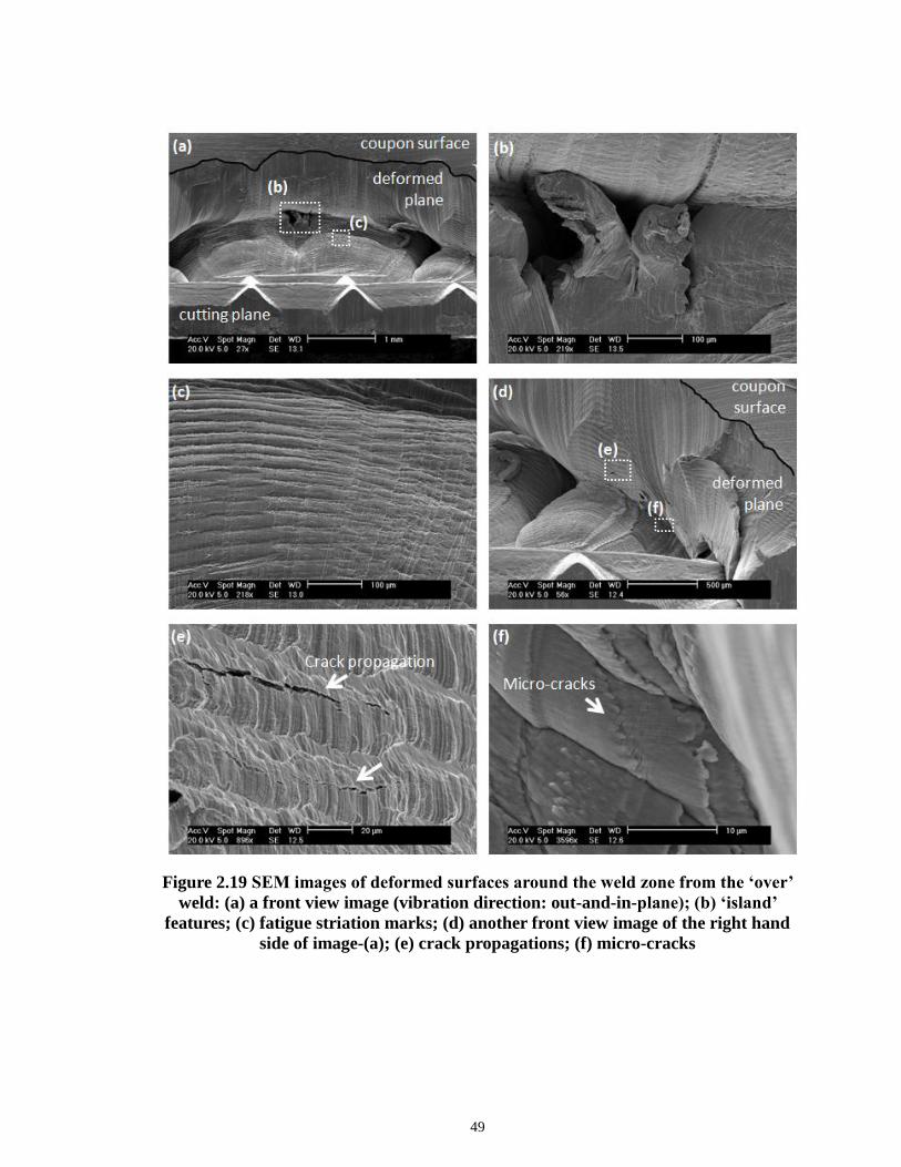
49
Figure 2.19 SEM images of deformed surfaces around the weld zone from the ‘over’
weld: (a) a front view image (vibration direction: out-and-in-plane); (b) ‘island’
features; (c) fatigue striation marks; (d) another front view image of the right hand
side of image-(a); (e) crack propagations; (f) micro-cracks

50
2.4.5 Summary of correlation between weld attributes and quality
The relationship between the weld performance and two attributes (i.e., bond
density and post-weld thickness) is summarized in Figure 2.20, plotted against weld time.
The bond density is increasing over weld time due to an expansion of the micro-bonds at
the weld interface, and the post-weld thickness is decreasing due to material thinning.
The highest joint strength is shown in the middle at a weld time of about 0.6 sec. This
shows that a good quality weld in ultrasonic welding is achieved when the interfacial
bond reaches a level of enough metallurgical adhesion and mechanical interlocking, but
the material thinning has not progressed to the extent to severely reduce the mechanical
strength.
Figure 2.20 Correlation of weld performance with bond density and post-weld
thickness
0.2 0.4 0.6 0.8 1.00
100
200
300
400
500
600
700
Ma
x U
-te
nsile
Lo
ad
(N
)
Max U-tensile Load (N)
Bond Density (%)
Post-weld Thickness (%)
Weld Time (sec)
0
20
40
60
80
100
Bo
nd
De
nsity (
%)
0
10
20
30
40
Po
st-
we
ld T
hic
kn
ess (
%)

51
2.5 CONCLUSIONS
A set of measurable weld attributes have been proposed to characterize
ultrasonically welded joints of copper and nickel plated copper. The joint characteristics
of different quality welds were investigated using those attributes and the relationship
between attributes and performance was quantitatively identified.
The main conclusions of this chapter are as follows:
1) The bonding strength of ultrasonically welded joints for copper and nickel-
plated copper is due to the combined effect of metallurgical adhesion (micro-
bonds) and mechanical interlocking.
2) Different levels of weld quality (i.e., under, good, or over weld) are correlated
to the combination effect of the bonded area density and the post-weld
thickness, which show opposite tendencies.
3) Material flow with extensive plastic deformation occurs at the metal surface in
contact with each horn tooth, and causes material thinning or indentation.
Indentation of the metal surface intensifies as welding proceeds, and its rate
also differs in different quality regions: fast indentation rate in under weld
samples, slowing down in good weld and regaining the indentation rate in
over weld.
4) Material that has received high ultrasonic energy input show instant work
hardening due to the cold working and then softening with continuous

52
temperature increase, which resembles an annealing process (i.e., recovery,
recrystallization, and grain growth).
5) Various zones in an ultrasonic metal weld are distinguished by their
mechanical properties and micrographs: Weld Nugget (WN), Thermo-
Mechanically Affected Zone (TMAZ), and Base Material (BM). The sizes of
TMAZ and WN affect the failure type during performance testing and,
eventually, weld quality.
A set of well-defined weld attributes help to link welding process variables with
weld quality based on an understanding of the characteristics of the weldment. The
scientific understanding obtained from this chapter can guide manufacturers in
establishing robust process parameter regions to achieve consistent quality. The
methodology on identifying these weld attributes will be extended to multi-layer welding
in our future work.
ACKNOWLEDGEMENT
The work presented here is sponsored by the General Motors Collaborative Research
Lab in Advanced Vehicle Manufacturing at the University of Michigan. The authors
appreciate the support provided by Dr. Kai Sun at the University of Michigan Electron
Microbeam Analysis Laboratory (EMAL).

53
REFERENCES
Bakavos, D. and Prangnell, P. B. (2010). "Mechanisms of Joint and Microstructure
Formation in High Power Ultrasonic Spot Welding 6111 Aluminium Automotive
Sheet." Materials Science and Engineering: A 527(23): 6320-6334.
Cáceres, C. H., Griffiths, J. R., Pakdel, A. R. and Davidson, C. J. (2005). "Microhardness
Mapping and the Hardness-Yield Strength Relationship in High-Pressure Diecast
Magnesium Alloy Az91." Materials Science and Engineering: A 402(1-2): 258-
268.
Cheng, X. and Li, X. (2007). "Investigation of Heat Generation in Ultrasonic Metal
Welding Using Micro Sensor Arrays." Journal of Micromechanics and
Microengineering 17: 273.
Geuser, F. D., Bley, F., Denquin, A. and Deschamps, A. (2010). Mapping the
Microstructure of a Friction-Stir Welded (Fsw) Al-Li-Cu Alloy. Journal of
Physics, IOP Publishing.
Gunduz, I. E., Ando, T., Shattuck, E., Wong, P. Y. and Doumanidis, C. C. (2005).
"Enhanced Diffusion and Phase Transformations During Ultrasonic Welding of
Zinc and Aluminum." Scripta materialia 52(9): 939-943.
Hetrick, E., Baer, J., Zhu, W., Reatherford, L., Grima, A., Scholl, D., Wilkosz, D., Fatima,
S. and Ward, S. (2009). "Ultrasonic Metal Welding Process Robustness in
Aluminum Automotive Body Construction Applications." Welding Journal 88(7).
Hu, S. J., Senkara, J. and Zhang, H. (1996). "Performance Characteristics of Resistance
Spot Welds in the Automotive Industry: A Structural Point of View." Proceedings
of IBEC' 96 Body & Engineering: 91-98.
Ji, H., Li, M., Kung, A. T., Wang, C. and Li, D. (2005). The Diffusion of Ni into Al Wire
at the Interface of Ultrasonic Wire Bond During High Temperature Storage.
Electronic Packaging Technology, 2005 6th International Conference on.
Joshi, K. C. (1971). "The Formation of Ultrasonic Bonds between Metals." Welding
Journal 50(12): 840-848.
Kim, T. H., Yum, J., Hu, S. J., Spicer, J. P. and Abell, J. A. (2011). "Process Robustness
of Single Lap Ultrasonic Welding of Thin, Dissimilar Materials." CIRP Annals -
Manufacturing Technology 60(1): 17-20.

54
Kong, C., Soar, R. and Dickens, P. (2003). "Characterisation of Aluminium Alloy 6061
for the Ultrasonic Consolidation Process." Materials Science and Engineering A
363(1-2): 99-106.
Kong, C., Soar, R. and Dickens, P. (2004). "Optimum Process Parameters for Ultrasonic
Consolidation of 3003 Aluminium." Journal of Materials Processing Technology
146(2): 181-187.
Kreye, H. (1977). "Melting Phenomena in Solid State Welding Processes." Welding
Journal 56(5): 154-158.
Lee, S. S., Kim, T. H., Hu, S. J., Cai, W. and Abell, J. A. (2010). "Joining Technologies
for Automotive Lithium-Ion Battery Manufacturing: A Review." ASME
Conference Proceedings 2010(49460): 541-549.
Li, J., Han, L. and Zhong, J. (2008). "Short Circuit Diffusion of Ultrasonic Bonding
Interfaces in Microelectronic Packaging." Surface and Interface Analysis 40(5):
953-957.
Prangnell, P. B. and Heason, C. P. (2005). "Grain Structure Formation During Friction
Stir Welding Observed by the `Stop Action Technique'." Acta Materialia 53(11):
3179-3192.
Ram, G. D. J., Robinson, C., Yang, Y. and Stucker, B. (2007). "Use of Ultrasonic
Consolidation for Fabrication of Multi-Material Structures." Rapid Prototyping
Journal 13(4): 226-235.
Steuwer, A., Dumont, M., Altenkirch, J., Birosca, S., Deschamps, A., Prangnell, P. and
Withers, P. (2011). "A Combined Approach to Microstructure Mapping of an Al-
Li Aa2199 Friction Stir Weld." Acta Materialia.
Yang, Y., Ram, G. D. J. and Stucker, B. E. (2010). "An Analytical Energy Model for
Metal Foil Deposition in Ultrasonic Consolidation." Rapid Prototyping Journal
16(1): 20-28.
Zhang, C. and Li, L. (2009). "A Coupled Thermal-Mechanical Analysis of Ultrasonic
Bonding Mechanism." Metallurgical and Materials Transactions B 40(2): 196-207.
Zhou, B., Thouless, M. and Ward, S. (2006). "Predicting the Failure of Ultrasonic Spot
Welds by Pull-out from Sheet Metal." International journal of solids and
structures 43(25-26): 7482-7500.

55
Zhou, B., Thouless, M. D. and Ward, S. (2005). "Determining Mode-I Cohesive
Parameters for Nugget Fracture in Ultrasonic Spot Welds." International Journal
of Fracture 136(1): 309-326.
Zhou, M., Hu, S. J. and Zhang, H. (1999). "Critical Specimen Sizes for Tensile-Shear
Testing of Steel Sheets." Welding Journal (Miami, Fla) 78(9).
Zhou, M., Zhang, H. and Hu, S. J. (2003). "Relationships between Quality and Attributes
of Spot Welds." Welding Journal (Miami, Fla) 82(Compendex): 72S-77S.

* The contents of this chapter are ready to be submitted to ASME Journal of Manufacturing Science and
Engineering.
56
CHAPTER 3
CHARACTERIZATION OF ULTRASONIC METAL WELDING BY
CORRELATING ONLINE SENSOR SIGNALS WITH WELD
ATTRIBUTES*
ABSTRACT
Online process monitoring using sensors in ultrasonic welding of lithium-ion
batteries for automotive applications is essential for a robust and reliable battery pack
assembly. Although monitoring algorithms can be developed by systematic feature
extraction and selection without expert knowledge of the process, the selected online
features may not be repeatable when facing untrained data sets. The purpose of this study
is to establish an in-depth understanding of sensor signals and their relationship to the
ultrasonic welding process and joint quality. The fundamental physics behind the
ultrasonic welding process is investigated using two sensor signals, weld power and horn
displacement. Several online features are identified by examining those sensor signals
and their variations under abnormal process conditions. The joint quality is predicted by
correlating such online features to weld attributes such as bond density and post-weld
thickness that directly impact the weld performance. This study provides a guideline for
feature selection to achieve a reliable online monitoring system in ultrasonic metal
welding.

57
3.1 INTRODUCTION
Ultrasonic metal welding is one of the major processes used to join automotive
lithium-ion batteries [Lee et al. 2010; Kim et al. 2011; Lee et al. 2013]. In ultrasonic
metal welding, a high frequency shear oscillation generated by a piezoelectric system, as
described in Figure 3.1, removes surface oxides or contamination by friction [Zhang and
Li 2009]. The continuous scrubbing action under pressure yields an increase in contact
area, resulting in metallurgical adhesion [Kong et al. 2003; 2005; Siddiq and Ghassemieh
2009] or diffusion [Gunduz et al. 2005; Li et al. 2008] at the exposed metal interfaces.
These solid-state bonding characteristics are advantageous for joining dissimilar metals
such as copper, aluminum and nickel, which are commonly used materials for battery
tabs. In addition, the temperature in this process does not exceed the melting point of the
metal workpiece, eliminating undesirable compounds, phase, and metallurgical defects
that can result from most fusion welding processes [Annoni and Carboni 2011].
Therefore, the ultrasonic welding process is well suited for battery tab joining.
Figure 3.1 Ultrasonic metal welding system and sensor signal acquisition
Transducer Booster Horn
Controller
Anvil
LVDT
Watt meter
PCDAQ
Workpiece

58
In a typical battery pack for hybrid and electric vehicles, several hundred battery
cells are joined together through tabs and bus-bars to meet the desired power and energy
capacity requirements. The battery joints should possess reliable electrical connections as
well as robust mechanical strength because failure of a single weld can result in
degradation, even failure, of battery pack performance. Therefore, quality inspection is
essential to ensure acceptable quality on every battery joint. As a quality assurance
method, online process monitoring is widely used in manufacturing to ensure joint
quality and process stability [Chu et al. 2004; Hu et al. 2011]. Although monitoring
algorithms can be developed by systematic feature selection from various sensor signals
utilizing appropriate statistical methods without expert knowledge of the process [Shao et
al. 2013], selected features may not perform well when new abnormal process conditions
are encountered. Thus, in order to develop a robust and reliable monitoring system, an in-
depth understanding of sensor signals and their relationship to the welding process and
eventually to weld quality should be established.
A significant amount of research has been done on the relationship between
sensor signals and weld quality for various welding technologies. For example, Ling et al.
[2010] predicted the quality of resistance spot welds by analyzing input voltage and
current signals during the welding process. Li et al. [2000] estimated the resistance spot
weld quality by correlating online signal features such as dynamic resistance with nugget
size. Tseng and Chuang [2012] showed the influence of maximum electrode
displacement on the nugget diameter and thickness in predicting spot weld quality. Park
and Kim [2012] indicated that the plasma light intensity obtained by optical sensors could
express the plasma/keyhole behavior, which directly impacts laser weld quality. A

59
comprehensive review was performed by Sun et al. [1999] on the usage of multiple
sensors in real-time monitoring of laser weld quality and incorporation of sensor fusion
with a neural network approach. In gas metal arc welding, the welding voltage and
current signals were correlated to the weld quality using a statistical process control
method by Wu et al. [2007]. Nevertheless, only limited research has been carried out on
the sensor signals and their relationship to weld quality in ultrasonic metal welding. Or et
al. [1998] utilized a piezoelectric sensor to evaluate the weld quality during the ultrasonic
wire-bonding process, which was different from ultrasonic welding for sheet metals.
They monitored the changes in resonant frequency or vibration amplitude caused by
mechanical impedance change in the bonding zone. Zhao et al. [2013] developed a
measurement system for monitoring transient temperature during the ultrasonic welding
process using thin-film thermocouples fabricated on silicon substrates and inserted in a
pre-machined slot in the weld tool. Their study showed that the heat flux and its rate
change during the welding process provides good physical understanding of ultrasonic
bonding at the weld interface [Li et al. 2013]. The methodology provided in their study
showed some feasibility for process monitoring and control. However, no further
examination was conducted on how the temperature would vary when abnormal
situations occurred during the process.
In the previous study on ultrasonic welding of battery tabs [Lee et al. 2013],
several weld attributes such as bond density (BD) and post-weld thickness (PWT) were
identified from optical micrographs and correlated to weld quality. According to this
study, the performance of an ultrasonic metal weld, such as mechanical strength, can be
indirectly linked to process parameters through such attributes. However, there are

60
limitations of using weld attributes for process monitoring since they are only available
through off-line post weld measurement. Therefore, this chapter attempts to investigate
the fundamental physics behind the weld formation in ultrasonic welding using sensor
signals and relating them to weld attributes, which in turn determine the weld quality.
The remainder of this chapter is organized as follows. Section 3.2 summarizes
weld formation mechanism in ultrasonic metal welding. Section 3.3 describes the
experimental procedure and sensor signals and analyzes signal variation under abnormal
process conditions. Section 3.4 identifies the relationship between signal features and
weld attributes, which provides direct information of weld quality. Section 3.5
summarizes and concludes the chapter.
3.2 WELD FORMATION MECHANISM IN ULTRASONIC METAL
WELDING
Ultrasonic metal welding is a solid-state welding process. The frictional work
between the workpiece generated from the high frequency shear scrubbing in
combination with the normal force breaks and disperses the surface films (oxides,
contaminants, etc.), and increases the actual contact area at the weld interface. This, in
turn, leads to a local intimate contact between exposed metal surfaces to form
metallurgical bonds, which are atomic bonds between the metal lattices [Gao and
Doumanidis 2002]. These locally created bonds (i.e., micro-welds) increase in density
over the region affected by the weld tip as a result of the rise in temperature caused by
extensive plastic deformation. In addition to the metallurgical adhesion, the continuous
shear motion and static force from the horn result in bonding lines that curl around the

61
micro-welds, and they play a role in mechanical interlocking. Thus, a weld in ultrasonic
metal welding of similar materials, nickel-plated copper in this chapter, is formed mainly
by metallurgical adhesion with partial aid of mechanical interlocking. Ultrasonic metal
welding does not create any fusion zone where the temperature of the mating metals
reaches the melting point.
Figure 3.2 shows the microstructure of cross-sectioned weld samples of 1.0mm
nickel plated copper and 0.4mm copper (C11000). After the nickel layer (less than 2μm)
is broken by the oscillating shear force, a unified grain structure between the two bare
copper sheets is formed as shown in Figure 3.2(a). The nickel layer broken as pieces and
curled along the weld line, as shown in Figure 3.2(b), provides additional mechanical
strength.
(a) (b)
Figure 3.2 Optical micrographs with two main bonding mechanisms for ultrasonic
metal welds: (a) metallurgical adhesion; and (b) mechanical interlocking [Lee et al.
2013]
In this chapter, two key weld attributes which have a direct impact on the final
weld performance, BD and PWT, are measured and correlated with signal features. BD is
the proportion of bonded region to the entire weld width while PWT is the proportion of

62
the indented thickness of the upper sheet to the original thickness. These non-dimensional
parameters were defined in a previous study of joint quality characterization in ultrasonic
metal welding by Lee et al [Lee et al. 2013]. Figure 3.3 shows the effect of a key process
variable, weld time, on joint performance, BD and PWT. As shown in Figure 3.3(a), the
weld strength increases dramatically in a short welding time. Then it shows a slow
increase as welding time keeps increasing despite a steady increase of BD as described in
Figure 3.3(b). This is caused by the decrease of PWT over time as shown in Figure 3.3(c),
which may lead to excessive thinning of the material. Based on these results, the
performance of an ultrasonic metal weld is in positive relation with BD while in negative
relation with PWT. The process variation with contaminated surface in Figure 3.3 is
detailed in the next section.
3.3 SENSOR SIGNALS FROM THE ULTRASONIC WELDING
PROCESS
In this section, the signals collected by the sensors equipped in an AmTech
Ultraweld® L-20 high power welder are analyzed to describe the mechanism of weld
formation during the ultrasonic welding process. The experimental procedure is described
in Section 3.3.1. Two sensor signals, power and displacement, are introduced in Section
3.3.2, and their variations under surface contamination are examined in Section 3.3.3.
3.3.1 Experiment
Prepared coupons of nickel plated copper sheets of dimensions 20 mm by 50 mm

63
(a)
(b)
(c)
Figure 3.3 Influence of weld time on (a) weld strength obtained from U-tensile test;
(b) bond density; and (c) post-weld thickness
0.1 0.2 0.3 0.4
0
50
100
150
200
250
300
Weld
Str
ength
(N
)
Weld Time (Sec)
Contam. Level 0
Contam. Level 1
Contam. Level 2
Contamination
Level 0
Level 1
Level 2
0.1 0.2 0.3 0.4
0.0
0.1
0.2
0.3
0.4
0.5
Bond D
ensity
Weld Time (Sec)
0.1 0.2 0.3 0.4
0.4
0.6
0.8
P-W
Thic
kn
ess
Weld Time (Sec)
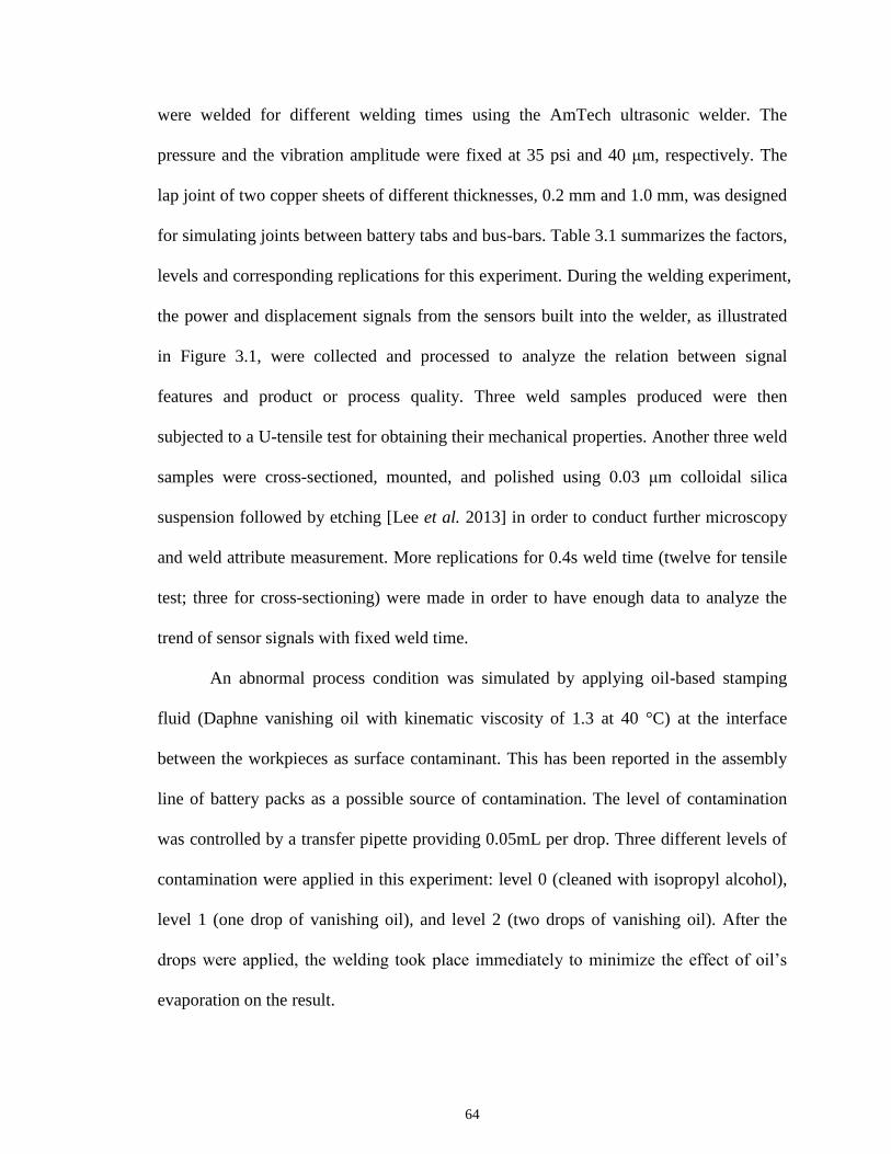
64
were welded for different welding times using the AmTech ultrasonic welder. The
pressure and the vibration amplitude were fixed at 35 psi and 40 μm, respectively. The
lap joint of two copper sheets of different thicknesses, 0.2 mm and 1.0 mm, was designed
for simulating joints between battery tabs and bus-bars. Table 3.1 summarizes the factors,
levels and corresponding replications for this experiment. During the welding experiment,
the power and displacement signals from the sensors built into the welder, as illustrated
in Figure 3.1, were collected and processed to analyze the relation between signal
features and product or process quality. Three weld samples produced were then
subjected to a U-tensile test for obtaining their mechanical properties. Another three weld
samples were cross-sectioned, mounted, and polished using 0.03 μm colloidal silica
suspension followed by etching [Lee et al. 2013] in order to conduct further microscopy
and weld attribute measurement. More replications for 0.4s weld time (twelve for tensile
test; three for cross-sectioning) were made in order to have enough data to analyze the
trend of sensor signals with fixed weld time.
An abnormal process condition was simulated by applying oil-based stamping
fluid (Daphne vanishing oil with kinematic viscosity of 1.3 at 40 °C) at the interface
between the workpieces as surface contaminant. This has been reported in the assembly
line of battery packs as a possible source of contamination. The level of contamination
was controlled by a transfer pipette providing 0.05mL per drop. Three different levels of
contamination were applied in this experiment: level 0 (cleaned with isopropyl alcohol),
level 1 (one drop of vanishing oil), and level 2 (two drops of vanishing oil). After the
drops were applied, the welding took place immediately to minimize the effect of oil’s
evaporation on the result.

65
Table 3.1 Factors and levels for experimental design
Welding time
(sec)
Surface
contamination
Replications
U-tensile test Post-weld measurement
0.1 Level 0 3 3
0.1 Level 1 3 3
0.1 Level 2 3 3
0.2 Level 0 3 3
0.2 Level 1 3 3
0.2 Level 2 3 3
0.3 Level 0 3 3
0.3 Level 1 3 3
0.3 Level 2 3 3
0.4 Level 0 12 3
0.4 Level 1 12 3
0.4 Level 2 12 3
3.3.2 Sensor signals
Two sensor signals are analyzed: (1) the electric power required for maintaining
the mechanical vibration of the weld tool (i.e., horn) and (2) the linear displacement of
the horn in the clamping direction.
Power
The ultrasonic vibration is provided by a piezoelectric system and transmitted to a
booster/horn stack assembly with designated amplitude. To maintain this mechanical
vibration at a constant level of amplitude, the amount of electrical power is controlled
throughout the welding process depending upon the mechanical loading conditions on the
weld joint, which may vary during the process. The power can be defined as:

66
( )dS tPower F
dt (1)
where F is the force exerted on the weld tip as a function of friction coefficient (μ) and
clamping force (FN), and dS(t)/dt is the velocity profile of the weld tip function.
Figure 3.4 shows (a) the power required to initiate and maintain the vibration
motion of the horn during the weld cycle and (b) the cross-section images of the weld
interface over welding time. As shown in Figure 3.4(a), the power rapidly ramps up for
the initial 0.1 second of welding time and stays at a constant level to maintain the
vibration. As ultrasonic energy is transmitted to the weld interface, the shear force
generated from the high frequency lateral movement results in yielding of the material.
Extensive plastic deformation or cold work is observed in the elongated grains along the
bonding line as seen in the initial stage of weld process (Figure 3.4(b)). As welding
proceeds, severely deformed grains and the migration of high angle grain boundaries lead
to the formation of a new grain structure (i.e., recrystallization) [Bakavos and Prangnell
2010; Patel et al. 2011; Prangnell et al. 2011], and a continuous welding action with
increased temperature results in growth of the recrystallized grains [Lee et al. 2013].
Those recrystallized grain structures are seen in most normal quality welds, which have
already been described in many previous studies [Bakavos and Prangnell 2010; Patel et al.
2011; Prangnell et al. 2011; Lee et al. 2013]. This is mainly due to the temperature rise at
the weld interface with the aid of severe cold working of the material, which is caused
from the dissipation of mechanical energy (i.e., vibration) by friction. Therefore, such
power signals that are influenced by the surface condition of the mating metal sheets can
provide useful information on the weld formation process.

67
(a)
(b)
Figure 3.4 Power signal variation over time: (a) power profile for a single welding
cycle; and (b) continuous cross-section images at the weld interface during welding
cycle
Displacement
A Linear variable differential transformer (LVDT) was used to measure the horn
displacement in the clamping direction. This signal data provides information on
mechanical deformation, or indentation, made by the teeth of the horn.
The displacement profile as shown in Figure 3.5(a) shows the trend typically seen
in normal quality welds. In the initial stage of the welding process (< 0.05 sec), the
indentation of the material occurs at relatively high speed, but at a lower speed after that
(> 0.05 sec). Figure 3.5(b) describes a series of cross-section images that impose a
material filling phenomenon into the space between knurl teeth. Based on the findings
0.0 0.1 0.2 0.3 0.4
0
1
2
3
4
5
Po
we
r (V
)
Weld time (sec)
iviiiii
i
v
iviiiiii v
50µm 50µm 50µm 50µm 50µm

68
from the previous study [Lee et al. 2013], the quality of ultrasonic welds has a close
relationship with an indented thickness of the material. Thus, the linear displacement
profile of the horn can be utilized as valuable data for process monitoring.
(a)
(b)
Figure 3.5 LVDT signal: (a) profile of horn displacement; (b) cross-section images at
the top of metal surface illustrating material filling behavior that corresponds to the
displacements shown in (a)
3.3.3 Signal variation under process disturbance
As discussed in Section 3.1, process disturbance during the ultrasonic welding
process for battery tab joining was simulated by contaminating the workpiece surface
with stamping fluid. The weld samples produced with three different levels of
contamination – level 0, level 1 and level 2 – are examined by microscopy.
iviiiii
i
0.0 0.1 0.2 0.3 0.4
3.36
3.38
3.40
3.42
3.44V
ert
ica
l D
isp
lace
me
nt
(V)
Weld time (sec)
ii iii ivi

69
Figure 3.6(a) illustrates the typical trend of power signals for the three
contamination levels during the welding process. 15 replicated signals were collected
from the welding experiment, and all showed similar patterns. The power for welding of
materials with clean surface shows a fast increase up to about 2300W, followed by a
steady power level until welding is over, whereas the power for both contaminated cases
does not reach the same power requirement as the clean surface case but only 70% to 75%
of that (stage I in Figure 3.6). Instead, the power decreases over a period of time (stage II)
and gradually increases again (stage III) before settling as the end of the weld cycle is
reached (stage IV). The lack of power ramp-up in stage I and continuous reduction in
stage II for the contaminated surface cases mainly come from the low frictional resistance
to the relative motion of metal sheets due to the slippery surface, so the welder does not
require such high power to maintain the vibration with the designated amplitude.
However, once the contaminants of the surface have been dispersed or removed by the
scrubbing action, the welder regains its power in stage III as the friction resistance
recovers back to the normal condition. The time duration for stage II depends on the
amount of contamination at the interface as shown in Figure 3.6(a).
Figure 3.6(b) shows the variation of the horn’s absolute position during welding
of copper sheets of different contamination levels. The same stage division as the power
signal can be applied to this LVDT signal. At stage I, the horn abruptly decreases its
position as the weld tool penetrates the metal surface even though the depth of
indentation with contaminated surface differs from one with clean surface. For surface
contamination cases, the low power level in stage I causes less heat generation, which
results in less softening of the material and, therefore, less indentation. This penetration

70
helps the weld tool fully engaged in the metal surface. After the initial indentation, the
horn slows down its descent in stage II while very little descent is made for the
contaminated surface case due to the decrease in power. Then, as the welder increases
power again in stage III, the speed at which the horn is descending is regained whereas
the horn slows down for clean surface case.
(a)
(b)
Figure 3.6 Variation of (a) power signal and (b) displacement signal for different
levels of surface contamination
I II III IV
0.0 0.1 0.2 0.3 0.4
0
500
1000
1500
2000
2500
Po
we
r (W
atts)
Weld time (sec)
Contam. Level 0
Contam. Level 1
Contam. Level 2
I II III IV
0.0 0.1 0.2 0.3 0.4
-0.2
-0.1
0.0
Dis
pla
ce
me
nt
(mm
)
Weld time (sec)

71
Figure 3.7 is a series of microscopic images focused at the weld interface of a
weld sample with clean surface. It shows that, as power increases and the horn lowers its
altitude, the nickel layer is dispersed or broken apart by a shear force exerted on the
interface. Micro-welds are developed along the weld line, which becomes curled as
welding proceeds. The micrographs shown in Figure 3.8 indicate that the contaminants
are trapped in the weld interface and formed as a swirl, which makes the joint weaker.
This is because the remaining oil layer in the early stages of the welding process hinders
the adhesion of two metal surfaces and delays the weld development.
Figure 3.7 Optical micrographs showing weld line formation with welding time of (a)
0.1s, (b) 0.2s, (c) 0.3s, and (d) 0.4s

72
Figure 3.8 Optical micrographs at the weld interface for three levels of surface
contamination: (a) level 0 (clean); (b) level 1; and (c) level 2
3.4 RELATIONSHIP BETWEEN WELD ATTRIBUTES AND SIGNAL
FEATURES
In this section, signal features are correlated to weld attributes to identify the
relationship between sensor signals and product quality. First, Section 3.4.1 introduces
several features in power and displacement profiles. Then feature variations during the
welding process are presented in Section 3.4.2, and finally the relationship between those
features and weld attributes is presented in Section 3.4.3.
3.4.1 Features in sensor signals
Based on our understanding of the physics behind the signal variation under
process disturbance as discussed in Section 3.3, the early stages of the welding process is
crucial for sensing some abnormal process conditions. For example, the power required
in this period changes depending on the level of surface contamination due to different
friction conditions. These different power levels lead to different amounts of material
deformation, resulting in changes in horn displacement. Thus, the energy used and the
indentation depth in this early stages are two important features in both power and

73
displacement signals. For the simplicity of calculation, the energy is obtained from the
beginning to the mid-point of the welding process. In the same manner, the indentation
depth of the mid-point of the welding process is chosen as one feature of the
displacement signal. Those two features are named Emid and Dmid, respectively.
As discussed previously, an ultrasonic metal weld is formed through continuous
rubbing action that yields an increase of bonded areas between clean metal surfaces. The
curved weld line is found in typical weld samples with normal weld quality. The welding
experiments performed in this chapter show that the weld samples produced in 0.4s
welding time have the strongest joint performance owing to high bond density and
reasonable indentation depth, as described in Figure 3.3. Therefore, the normal quality
weld requires a certain level of welding time or energy input. In that sense, total energy
used and total indentation depth during the entire welding process are also important
features in the power and displacement curves. They are named Etotal and Dtotal,
respectively. Figure 3.9 illustrates the main features measured in the power and
displacement signals.
Figure 3.9 Features in power and displacement signals
Po
we
r (W
atts)
Weld time (sec)
Dis
pla
cem
ent (m
m)
Weld time (sec)12
T0 T
midDtotalD
0
totalE
midE
12
T T

74
Figure 3.10 shows the relationship between weld strength and each signal feature.
As shown in Figure 3.10(a) and (b), Etotal and Emid of the power signal for normal weld
samples is clearly distinguished from those for problematic welds caused by surface
contamination. Dmid, as a displacement signal feature, also shows the capability of
separating normal and defective weld groups as described in Figure 3.10(d) while Dtotal in
Figure 3.10(c) shows some capability to distinguish two weld groups but not as much as
Dmid does. All these four features show a linear relationship with joint performance,
indicating that the welds with higher strength possess higher Etotal, Emid, Dtotal or Dmid. As
indicated in all four plots, the amount of contaminants on the metal surface also affects
the level of weld energy or indentation depth.
(a) (b)
(c) (d) Figure 3.10 Relationship between weld performance and signal features: (a) Etotal; (b)
Emid; (c) Dtotal; and (d) Dmid
Defective
Normal
500 600 700 800 9000
40
80
120
160
200
240
280
Etotal
(J)
Contam. Level 0
Contam. Level 1
Contam. Level 2
U-t
ensile
Load (
N)
250 300 350 400
40
80
120
160
200
240
280
U-t
ensile
Load (
N)
Emid
(J)
0.08 0.12 0.16 0.20 0.240
40
80
120
160
200
240
280
U-t
en
sile
Lo
ad
(N
)
Dtotal
(mm)0.08 0.12 0.16 0.20
40
80
120
160
200
240
280
U-t
en
sile
Lo
ad
(N
)
Dmid
(mm)

75
3.4.2 Effect of welding parameters on signal features
For the signal features that have been identified, their relationship to a key process
variable, welding time, is established in this sub-section. Etotal and Dtotal are plotted
against welding time, as illustrated in Figure 3.11, which shows that Etotal and Dtotal
increase linearly over time regardless of the level of surface contamination. As welding
time increases, more ultrasonic energy is consumed for frictional heating, plastic
deformation and bond formation at the interface. Consequently, more heat generated by
increased weld energy yields softening of the material, resulting in deeper indentation by
the weld tool. However, only a fraction of the energy is used for welding a surface
contaminated workpiece. In the very early stages of the process (0.1s), approximately 160
J is consumed for welding clean metals whereas only 60% of this energy is used for both
contamination level 1 and 2, as indicated in Figure 3.11(a). As welding proceeds, the
energy consumption for contamination level 1 and level 2 increases at different rates. At
the very end of the welding process (0.4s), approximately 82% energy of the clean
surface case is used for level 1 contamination, and only 65% for level 2. This is because
the larger amount of contaminants the workpiece possesses, the longer time is taken for
removing the remaining contaminants by oscillating shears. Dtotal has a similar increasing
trend with increasing weld time as Etotal, as shown in Figure 3.11(b), but the increasing
rate depends on the level of contamination. For example, the difference in post
indentation depth from 0.1s to 0.4s for level 0 is 0.19 mm whereas that for level 1 and
level 2 is only 30% and 50% of level 0, respectively. In a similar manner to that for weld
energy, indentation for contaminated surface cases is slower than that for clean surface.
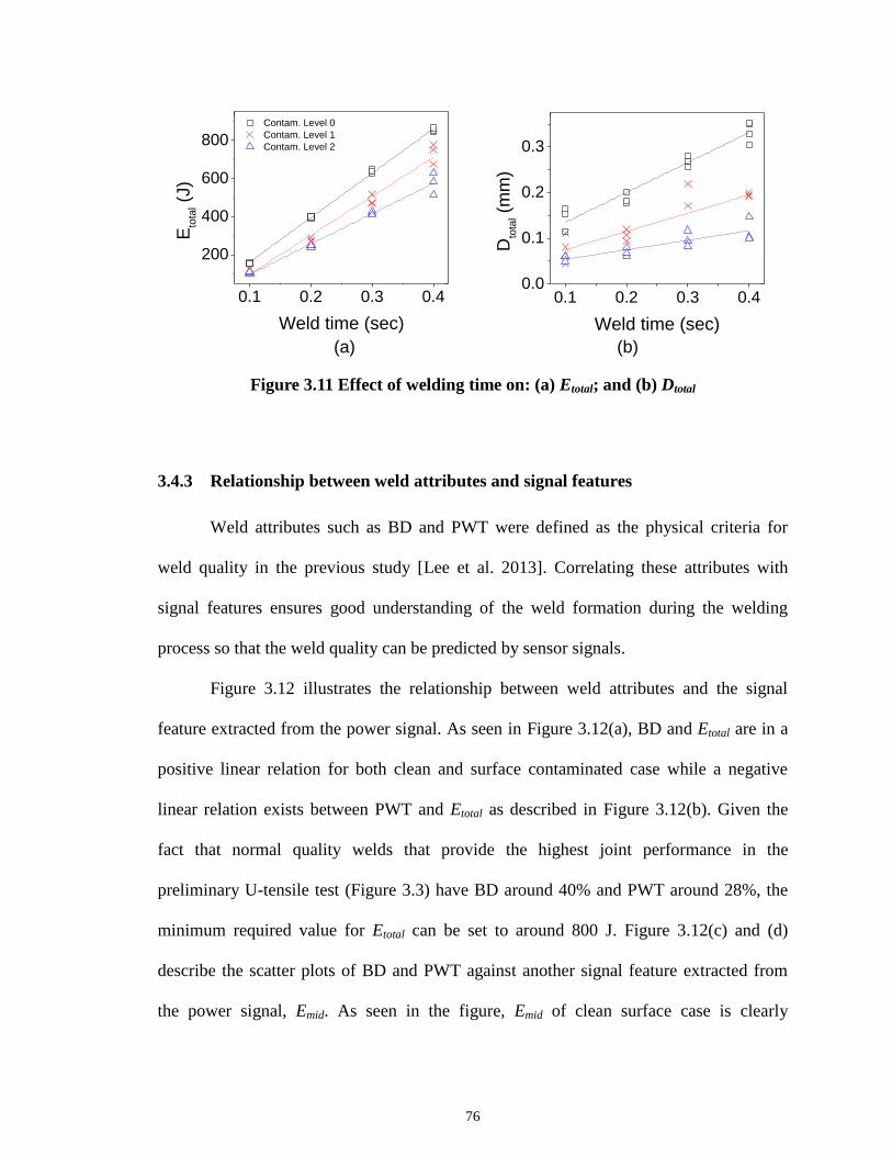
76
(a) (b)
Figure 3.11 Effect of welding time on: (a) Etotal; and (b) Dtotal
3.4.3 Relationship between weld attributes and signal features
Weld attributes such as BD and PWT were defined as the physical criteria for
weld quality in the previous study [Lee et al. 2013]. Correlating these attributes with
signal features ensures good understanding of the weld formation during the welding
process so that the weld quality can be predicted by sensor signals.
Figure 3.12 illustrates the relationship between weld attributes and the signal
feature extracted from the power signal. As seen in Figure 3.12(a), BD and Etotal are in a
positive linear relation for both clean and surface contaminated case while a negative
linear relation exists between PWT and Etotal as described in Figure 3.12(b). Given the
fact that normal quality welds that provide the highest joint performance in the
preliminary U-tensile test (Figure 3.3) have BD around 40% and PWT around 28%, the
minimum required value for Etotal can be set to around 800 J. Figure 3.12(c) and (d)
describe the scatter plots of BD and PWT against another signal feature extracted from
the power signal, Emid. As seen in the figure, Emid of clean surface case is clearly
0.1 0.2 0.3 0.4
200
400
600
800
Contam. Level 0
Contam. Level 1
Contam. Level 2
Eto
tal (
J)
Weld time (sec)
0.1 0.2 0.3 0.40.0
0.1
0.2
0.3
Dto
tal (
mm
)
Weld time (sec)

77
distinguished from that of contaminated surface case. This ability of separating normal
and problematic weld quality makes Emid a valuable feature for online monitoring. The
required energy level at the mid-point of welding process can be set to around 400 J in
order to achieve 40% BD and 28% PWT.
(a) (b)
(c) (d)
Figure 3.12 Relationship between weld attributes and power signal features: (a) BD
vs. Etotal; (b) PWT vs. Etotal; (c) BD vs. Emid; and (c) PWT vs. Emid
In addition to Etotal and Emid, Dtotal and Dmid also shows strong relationships to BD or
PWT as illustrated in Figure 3.13. Of those two features, Dmid, as shown in Figure 3.13(c)
and (d) has ability in discriminating between normal and defective weld groups that result
0 200 400 600 800 1000
0.0
0.1
0.2
0.3
0.4
0.5
Etotal
(J)
Contam. Level 0
Contam. Level 1
Contam. Level 2
Bo
nd
De
nsity
0 200 400 600 800 10000.2
0.4
0.6
0.8
1.0
Etotal
(J)
P-W
th
ickn
ess
240 280 320 360 4000.1
0.2
0.3
0.4
Bo
nd
De
nsity
Emid
(J)240 280 320 360 400
0.1
0.2
0.3
0.4
Bo
nd
De
nsity
Emid
(J)

78
from surface contamination. Process variation due to such abnormal condition mostly
occurs during the early welding stages. It should be noted that both Emid and Dmid are the
extracted features from the first half of the process. Dtotal of 0.25 mm or Dmid of 0.18 mm
can be set as desired values for required PWT of normal quality welds, as indicated in
Figure 3.13(a) and (b).
(a) (b)
(c) (d)
Figure 3.13 Relationship between weld attributes and displacement signal features:
(a) BD vs. Dtotal; (b) PWT vs. Dtotal; (c) BD vs. Dmid; and (c) PWT vs. Dmid
By correlating online features to weld attributes, the physics behind the signal
feature’s change under process variation are understood: for example, one can learn how
0.0 0.1 0.2 0.3 0.4
0.0
0.1
0.2
0.3
0.4
0.5
Dtotal
(mm)
Contam. Level 0
Contam. Level 1
Contam. Level 2
Bo
nd
De
nsity
0.0 0.1 0.2 0.3 0.40.2
0.4
0.6
0.8
1.0
P-W
th
ickn
ess
Dtotal
(mm)
0.08 0.12 0.16 0.20
0.28
0.32
0.36
0.40
0.44
P-W
Th
ickn
ess
Dmid
(mm)
0.08 0.12 0.16 0.200.1
0.2
0.3
0.4
Bo
nd
De
nsity
Dmid
(mm)

79
the feature variations are related to the change in geometric and mechanical attributes of
an ultrasonic weld. Figure 3.14 shows the scatter plots of four online features, which
enable the feasibility for online process monitoring to be ascertained.
Figure 3.14(a) shows the direct relationship between two signal features, Emid and
Dmid, halfway through the welding process, while Figure 3.14(b) shows the relationship
between two features, Etotal and Dtotal, collected after the process is over. Both Emid and
Etotal clearly distinguish problematic weld group (contamination level 1 and 2) from
normal quality group (level 0). Dmid and Dtotal also show this discriminative capability,
but not as clearly as Emid and Etotal in terms of the distance generated between two data
groups (normal vs. defective). Emid and Dmid, can be used as in-line monitoring signatures
since they capture the process variations in the early welding stages. A proper control
action can then be taken, based on the characteristics shown in those signatures. On the
other hand, Etotal and Dtotal can be used as post-weld monitoring signatures so that the
product quality after welding can be determined.
(a) (b)
Figure 3.14 Relationship between signal features: (a) Emid vs. Dmid; (b) Etotal vs. Dtotal
240 280 320 360 400
0.08
0.12
0.16
0.20
Emid
(J)
Contam. Level 0
Contam. Level 1
Contam. Level 2
Dm
id (
mm
)
500 600 700 800 900
0.08
0.12
0.16
0.20
0.24
Dto
tal (
mm
)
Etotal
(J)

80
3.5 CONCLUSIONS
In this study, two sensor signals, weld power and horn displacement, are
thoroughly examined to understand the physics behind the ultrasonic welding process.
Several signal features are identified, based on the physical understanding of signal
variations under abnormal process conditions such as surface contamination. These signal
features are then correlated to weld attributes measured from micrographs of cross-
sectioned weld samples. By achieving the relationship between those signal features and
weld attributes, the joint quality can be successfully predicted. In-depth characterization
of the ultrasonic metal welding process using sensor signals will help to understand the
impact of internal or external process variation on the weld quality. This study will also
provide a guideline for feature extraction/selection and setting criteria on selected
features in process monitoring of ultrasonic metal welding.
Specific conclusions are as follows:
1) Power signal provides useful information on the change of mechanical
resistance at the weld interface during the ultrasonic welding process whereas
displacement signal reflects the pattern for material deformation.
2) The power signal for the first half of the welding process provides critical
information on the mechanical loading on the weld tool. Low level of weld
power is shown in the early welding stages under process disturbance such as
low frictional surface due to stamping fluid. Similarly, the indentation at the
mid-point of the process as measured by LVDT also shows clear distinction
between normal and abnormal process conditions.

81
3) The energy used and the total indentation depth for the whole welding process
indicate whether the weld formation at the interface is completed.
4) The relationships between weld attributes and several signal features such as
Etotal, Emid, Dtotal, and Dmid provide physical understanding on the impact of
process conditions on the weld quality. They can be used to establish criteria
for weld quality monitoring.

82
REFERENCES
Annoni, M. and Carboni, M. (2011). "Ultrasonic Metal Welding of AA 6022-T4 Lap
Joints: Part I-Technological Characterisation and Static Mechanical Behaviour."
Science and Technology of Welding & Joining 16(2): 107-115.
Bakavos, D. and Prangnell, P. B. (2010). "Mechanisms of Joint and Microstructure
Formation in High Power Ultrasonic Spot Welding 6111 Aluminium Automotive
Sheet." Materials Science and Engineering: A 527(23): 6320-6334.
Chu, Y., Hu, S.J, Hou, W., Wang, P. and Marin, S. (2004). "Signature Analysis for
Quality Monitoring in Short-Circuit Gmaw." Welding journal 83(12): 336S-343S.
Gao, Y. and Doumanidis, C. (2002). "Mechanical Analysis of Ultrasonic Bonding for
Rapid Prototyping." Journal of Manufacturing Science and Engineering 124(2):
426-434.
Gunduz, I. E., Ando, T., Shattuck, E., Wong, P. Y. and Doumanidis, C. C. (2005).
"Enhanced Diffusion and Phase Transformations During Ultrasonic Welding of
Zinc and Aluminum." Scripta materialia 52(9): 939-943.
Hu, S.J, Hou, W., Du, H., Wang, P.-C. and Menassa, R. J. (2011). Method for
Controlling the Consistency of an Arc Welding Process by Monitoring Welding
Voltage to Determine Weld Droplet Detachment, Google Patents.
Kim, T. H., Yum, J., Hu, S. J., Spicer, J. P. and Abell, J. A. (2011). "Process Robustness
of Single Lap Ultrasonic Welding of Thin, Dissimilar Materials." CIRP Annals -
Manufacturing Technology 60(1): 17-20.
Kong, C., Soar, R. and Dickens, P. (2003). "Characterisation of Aluminium Alloy 6061
for the Ultrasonic Consolidation Process." Materials Science and Engineering A
363(1-2): 99-106.
Kong, C., Soar, R. and Dickens, P. M. (2005). "A Model for Weld Strength in
Ultrasonically Consolidated Components." Proceedings of the Institution of
Mechanical Engineers, Part C: Journal of Mechanical Engineering Science
219(1): 83-91.
Lee, S. S., Kim, T. H., Hu, S. J., Cai, W. and Abell, J. A. (2010). "Joining Technologies
for Automotive Lithium-Ion Battery Manufacturing: A Review." ASME
Conference Proceedings 2010(49460): 541-549.

83
Lee, S. S., Kim, T. H., Hu, S. J., Cai, W., Abell, J. A. and Li, J. (2013). "Characterization
of Joint Quality in Ultrasonic Welding of Battery Tabs." Journal of
Manufacturing Science and Engineering 135(2): 021004.
Li, H., Choi, H., Zhao, J., Li, X. C., Cai, W. and Abell, J. A. (2013). "Transient
Temperature and Heat Flux Measurement in Ultrasonic Joining of Battery Tabs
Using Thin-Film Micro Sensors." accepted by Journal of Manufacturing Science
and Engineering.
Li, J., Han, L. and Zhong, J. (2008). "Short Circuit Diffusion of Ultrasonic Bonding
Interfaces in Microelectronic Packaging." Surface and Interface Analysis 40(5):
953-957.
Li, W., Hu, S. J. and Ni, J. (2000). "On-Line Quality Estimation in Resistance Spot
Welding." Journal of manufacturing science and engineering 122(3): 511-512.
Ling, S.-F., Wan, L.-X., Wong, Y.-R. and Li, D.-N. (2010). "Input Electrical Impedance
as Quality Monitoring Signature for Characterizing Resistance Spot Welding."
NDT & E International 43(3): 200-205.
Or, S., Chan, H., Lo, V. and Yuen, C. (1998). "Ultrasonic Wire-Bond Quality Monitoring
Using Piezoelectric Sensor." Sensors and Actuators A: Physical 65(1): 69-75.
Park, Y. W. and Kim, D. (2012). "Optimization of Laser Welding Parameters in
Aluminum Alloy Welding and Development of Quality Monitoring System for
Light Weight Vehicle." Materials Science Forum 706-709: 2998-3003.
Patel, V. K., Bhole, S. D. and Chen, D. L. (2011). "Influence of Ultrasonic Spot Welding
on Microstructure in a Magnesium Alloy." Scripta Materialia 65(10): 911-914.
Prangnell, P., Haddadi, F. and Chen, Y. (2011). "Ultrasonic Spot Welding of Aluminium
to Steel for Automotive Applications: Microstructure and Optimisation."
Materials Science and Technology 27(3): 617-624.
Shao, C., Paynabar, K., Kim, T. H., Jin, J. J., Hu, S. J., Spicer, J. P., Wang, H. and Abell,
J. A. (2013). "Feature Selection for Manufacturing Process Monitoring Using
Cross-Validation." submitted to Journal of Manufacturing Systems.
Siddiq, A. and Ghassemieh, E. (2009). "Theoretical and Fe Analysis of Ultrasonic
Welding of Aluminum Alloy 3003." Journal of manufacturing science and
engineering 131(4): 041007.

84
Sun, A., Kannatey-Asibu Jr, E. and Gartner, M. (1999). "Sensor Systems for Real-Time
Monitoring of Laser Weld Quality." Journal of Laser Applications 11: 153.
Tseng, K. H. and Chuang, K. J. (2012). "Monitoring Nugget Size of Micro Resistance
Spot Welding (Micro Rsw) Using Electrode Displacement-Time Curve."
Advanced Materials Research 463: 107-111.
Wu, C., Gao, J. and Hu, J. (2007). "Real-Time Sensing and Monitoring in Robotic Gas
Metal Arc Welding." Measurement science and technology 18(1): 303.
Zhang, C. and Li, L. (2009). "A Coupled Thermal-Mechanical Analysis of Ultrasonic
Bonding Mechanism." Metallurgical and Materials Transactions B 40(2): 196-
207.
Zhao, J., Li, H., Choi, H., Cai, W., Abell, J. A. and Li, X. (2013). "Insertable Thin Film
Thermocouples for in Situ Transient Temperature Monitoring in Ultrasonic Metal
Welding of Battery Tabs." Journal of Manufacturing Processes 15(1): 136-140.

* The contents of this chapter are ready to be submitted to ASME Journal of Manufacturing Science and
Engineering.
85
CHAPTER 4
ANALYSIS OF WELD FORMATION IN MULTILAYER
ULTRASONIC METAL WELDING USING HIGH-SPEED IMAGES*
ABSTRACT
One of the biggest challenges in manufacturing automotive lithium-ion batteries is
to achieve consistent weld quality in joining multiple layers of dissimilar materials.
While most fusion welding processes face difficulties in such joining, ultrasonic welding
overcomes those difficulties due to its solid-state process characteristics. However,
inconsistency of weld quality still exists because of limited knowledge on the weld
formation through the multiple interfaces. This chapter aims to establish real-time
phenomenological observation on the multilayer ultrasonic welding process by analyzing
the vibration behavior of metal layers. Such behavior is characterized by a direct
measurement of the lateral displacement of each metal layer using high-speed images.
Two different weld tools are used in order to investigate the effect of tool geometry on
the weld formation mechanism and the overall joint quality. A series of microscopies and
bond density measurements is carried out to validate the observations and hypotheses of
those phenomena in multilayer ultrasonic welding. The results of this research enhance
the understanding of the ultrasonic welding process of multiple metal sheets and provide
insights for optimum tool design to improve the quality of multilayer joints.

86
4.1 INTRODUCTION
Ultrasonic metal welding creates a solid-state bond between metals using
oscillating shears generated by a high frequency ultrasonic energy. It has recently been
applied to joining lithium-ion batteries for hybrid and electric vehicles. This process is
well suited for such applications because of its ability in joining multiple layers of
dissimilar materials [Lee et al. 2013].
In the battery assembly, a large number of battery cells are connected through
bus-bars to meet the desired power and capacity requirement [Lee et al. 2010]. In such
configuration, multiple layers of dissimilar metals, mostly of copper, nickel or aluminum
as typical materials of anodes, cathodes, and bus-bars, are welded together. Achieving
consistent weld quality in those multiple weld interfaces is critical for good battery
performances.
While extensive research has been done on the weld formation of two metal
sheets in ultrasonic welding [Joshi 1971; Harthoorn 1973; Kreye 1977; Tucker 2002; De
Vries 2004; Zhang and Li 2009], only limited research has been carried out on multilayer
welding. Ram et al. [2006] presented layer-by-layer fabrication between multiple foils of
Al 3000 series using ultrasonic consolidation process in additive manufacturing. They
described the effects of process parameters on product quality in fabricating multiple
layers of similar materials and further investigated the weldability between multiple,
dissimilar materials, especially of Al alloys to brass or to stainless steel [Ram et al. 2007].
Obielodan et al. [2010] examined ultrasonic welding of several other multi-material
combinations, such as silver/copper/nickel, molybdenum/aluminum/copper,
aluminum/titanium, and nickel/stainless steel. However, most of these studies were

87
limited to demonstrating the ability of ultrasonic welding in joining multilayer dissimilar
materials. Recently, some research has been carried out on the ultrasonic welding of
multi-stacked batteries. Kang et al. [2012; 2013] presented the effect of structural
vibration that is generated from the ultrasonic welding process on weld quality in the
multilayer battery tab configuration. Lee et al. [2012] conducted research on the
ultrasonic welding of multiple, dissimilar metals by developing a mechanical-thermal
coupled finite element model. In their study, the temperature distribution within the
multi-material stack-up was obtained for a considerable amount of weld time (500 ms) by
the numerical simulation model. Nonetheless, there is still a lack of understanding on the
oscillating behavior of each metal sheet in multi-stacked configurations during the
ultrasonic welding process. Little effort has been made to identify how and in what order
the weld is created through multiple interfaces.
Several researchers investigated how the weld is developed at the interface during
the ultrasonic welding process by experiments and numerical simulations. Ji et al. [2005]
examined the cross section of Al+1%Si wire-bonded on the Au/Ni/Cu pad using scanning
electron microscopy with energy dispersive X-ray spectroscopy, and observed a large
number of vacancies and dislocations that can be fast diffusion paths across the weld
interface. Zhang and Li [2009] developed a dynamic temperature-displacement finite
element model to correlate process parameters with the weld development, whereas
Elangovan et al. [2009] introduced friction as a heat source to the workpiece in their
numerical model. Siddiq and Ghassemieh developed a theoretical [2009] as well as a
numerical model [2008] to investigate the effect of friction and material softening
88
behaviors on the temperature change at the interface. However, most of these studies lack
real-time phenomenological observation on weld development during the process.
In this chapter, the weld formation mechanism through the multiple interfaces is
investigated experimentally using high-speed images. High-speed imaging has been
widely used by many researchers for analyzing various welding techniques, for example,
laser welding [Eriksson et al. 2010; Eriksson et al. 2010] or arc welding [Zaal et al. 2008;
Ogawa 2011; Wen et al. 2011; 2012], but never been attempted for ultrasonic metal
welding due to its high speed process characteristics. However, recent developments in
high-speed imaging technology [AmeTek 2013] enable the observation of high frequency
oscillations of the metal sheets in ultrasonic welding.
The goal of this study is to characterize weld development in multilayer ultrasonic
welding through in-depth understanding of the vibration behavior of the metals. Such
behavior is analyzed by processing high-speed images obtained during the welding
process and measuring the lateral displacement of the workpiece. Different weld tools are
introduced to investigate their impact on the vibration behaviors, and ultimately on the
weld propagation mechanism. Furthermore, microscopic analyses and bond density
measurements provide additional information on weld development in multilayer
ultrasonic welding.
The remainder of this chapter is organized as follows: Section 4.2 describes
experimental setups and procedures; Section 4.3 discusses the results from high-speed
imaging and post-weld experiments; and Section 4.4 summarizes and concludes the
chapter.

89
4.2 EXPERIMENT
4.2.1 Ultrasonic welding process
Figure 4.1 describes a typical ultrasonic metal welding system. A piezoelectric
transducer converts a low frequency electrical signal to a high frequency, 20 kHz or
above, mechanical vibration. This mechanical vibration is amplified by a booster and
then transferred to a horn. The metal sheets to be joined are placed and clamped under
pressure between the horn and anvil. As welding begins, oscillating shears generated by
the welder breaks the oxide layers or contaminants and finally creates a solid-state bond
between the exposed metals. Because of such bonding characteristics, a wide range of
multiple, dissimilar metal sheets or thin foils can be joined by ultrasonic welding despite
the thickness limitation of workpiece to 3 mm [Lee et al. 2010].
Figure 4.1 Ultrasonic metal welding system
4.2.2 High speed imaging
In this study, the Phantom v1610 digital high-speed camera with a telescope lens
was used to record the dynamics of the metal workpiece during ultrasonic welding, as
Transducer Booster
Horn
Controller
Anvil
Electrical
energy Mechanical energy
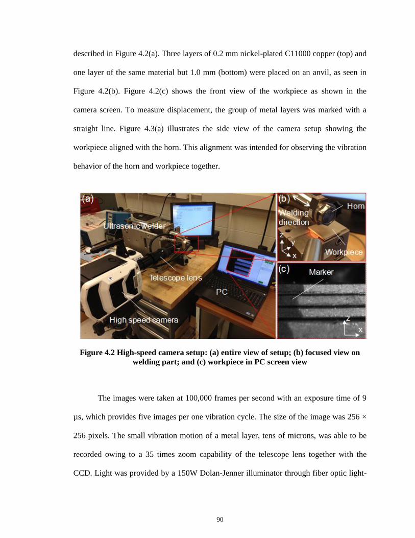
90
described in Figure 4.2(a). Three layers of 0.2 mm nickel-plated C11000 copper (top) and
one layer of the same material but 1.0 mm (bottom) were placed on an anvil, as seen in
Figure 4.2(b). Figure 4.2(c) shows the front view of the workpiece as shown in the
camera screen. To measure displacement, the group of metal layers was marked with a
straight line. Figure 4.3(a) illustrates the side view of the camera setup showing the
workpiece aligned with the horn. This alignment was intended for observing the vibration
behavior of the horn and workpiece together.
Figure 4.2 High-speed camera setup: (a) entire view of setup; (b) focused view on
welding part; and (c) workpiece in PC screen view
The images were taken at 100,000 frames per second with an exposure time of 9
µs, which provides five images per one vibration cycle. The size of the image was 256 ×
256 pixels. The small vibration motion of a metal layer, tens of microns, was able to be
recorded owing to a 35 times zoom capability of the telescope lens together with the
CCD. Light was provided by a 150W Dolan-Jenner illuminator through fiber optic light-

91
guides for high-speed imaging. Finally, the images were digitally obtained and processed
by Phantom camera control application software. The lateral displacement of each metal
layer was measured in the consecutive high-speed images as illustrated in Figure 4.3(b).
(a) (b)
Figure 4.3 Schematic of high-speed camera setup: (a) workpiece stack-up aligned
with horn (side view); and (b) displacement measurement of metal layer (front view)
4.2.3 Multilayer welding experiment
The multiple layers of nickel plated copper with different thicknesses were
welded by a 20 kHz, 3.6 kW, AmTech lateral-drive ultrasonic spot welder. Table 4.1
shows the input parameters and their levels. The clamping pressure and the horn vibration
amplitude were fixed at 50 psi and 60 µm, respectively. The weld time was varied to
analyze the weld formation through multiple interfaces during the welding process. The
input range of weld time was pre-determined by a screening test. Replication of each
parameter was ten: nine for T-peel testing and one for cross-sectioning. Two anvil types
with different knurl patterns (“fine” and “coarse”) were used to study the effect of the
anvil roughness on the weld formation in multilayer ultrasonic welding. Figure 4.4
High speed
cameraHorn
Anvil z
y
z
x
d1
d2
d3
d4
Marker
Horn
Anvil
Workpiece
Welding direction

92
describes the knurl patterns and their dimensions. It is expected that the difference in
anvil teeth geometry will cause different levels of material deformation, which eventually
affect the weld development at the bottom interface.
Table 4.1 Factors and levels for experimental design
Factor Level
Weld time (sec), T 0.1, 0.2, 0.3, 0.4, 0.5, 0.6
Anvil type Fine, coarse
Figure 4.4 Two anvil types and their knurl dimensions
4.2.4 Post-weld performance testing/ microscopy/ bond density measurement
As a multi-joint configuration, each weld sample has three interfaces: 1st, 2
nd and
3rd
. To evaluate the mechanical strength of multilayer joints, a T-peel test [Kim et al.
2011] per sample, as illustrated in Figure 4.5, was performed by an Instron testing
machine with a pulling speed of 10 mm/min. Of the nine T-peel samples, three are tested
for each interface. The maximum tensile load during the T-peel test was recorded. The
remaining one weld sample was cross-sectioned, mounted, polished, and applied to light
surface etching for further optical micrographs and bond density measurement. The
c d
b
a
(Unit: mm)
Type a b c d
Fine 0.127 0.254 0 90
Coarse 0.635 1.270 0 90
Fine Coarse

93
details of sample preparation and post-west measurement for ultrasonic metal welds were
fully described in the previous study [Lee et al. 2013].
Figure 4.5 T-peel test for multi-joint welds
4.3 RESULTS AND DISCUSSION
This section presents the results from high-speed imaging and post-weld
experiments. Based on these results, we discuss the weld formation mechanism in
multilayer welding as well as the effect of anvil geometry on the vibration behaviors of
the metal sheets and the weld development.
4.3.1 Observation of vibration development in multiple layers
Figure 4.6 shows an example of how the lateral displacement of one metal layer
varies in a single weld cycle of 5 x 10⁻⁵
second. As the horn vibrates with constant
amplitude, the workpiece also vibrates with it. The displacement of each layer is
measured from the high-speed images as seen in Figure 4.6(a), which shows six
1st weld interface 2nd weld interface 3rd weld interface

94
consecutive images taken at 0.00001 second intervals. These six images constitute a
vibration cycle as described in Figure 4.6(b).
(a)
(b)
Figure 4.6 Example of displacement variation in one weld cycle (5 x 10⁻⁵
second): (a)
consecutive high-speed images showing single vibration cycle of a metal layer; (b) an
illustration of displacement curve measured from (a)
Figure 4.7 describes the development of vibration cycles for each metal layer
during the initial 0.1s weld time. Each plot in Figure 4.7 shows two vibration cycles of
four metal layers at a weld time of 0.005s, 0.02s, 0.04s, 0.06s, 0.08s, and 0.1s. Each data
point in the plots is obtained by using the image processing algorithm in the Phantom
application software. The resolution of this measurement is approximately 3µm. Despite
the limitation of focal length of the telescope lens used in this experiment, the variation
cycles and their developing trends are clearly shown. The weld time 0.005s in Figure 4.7
(a) represents the vibration cycles at the very beginning of the welding process, and the
500µm 500µm 500µm 500µm500µm500µm
0.0
60
01
s
0.0
60
02
s
0.0
60
03
s
0.0
60
04
s
0.0
60
05
s
0.0
60
06
s
i ii iii iv v vi
Weld time
Late
ral
dis
pla
cem
en
t
i
ii
iii iv
v
vi

95
rest of the figures (Figure 4.7(b)-(f)) show the progress of the vibrations with increment
of 0.02s weld time. The following observations can be made from the figure.
In two consecutive cycles, very little difference in the vibration magnitude
exists.
When the observations are made sufficiently apart from each other, then a
clear increase in the vibration magnitude can be seen. Each layer experiences
an increase in vibration amplitude during the initial 0.1s of weld time, which
can be called “growth” of the vibration of the layers.
The vibration magnitude is highest in the top layer, but the vibration of the
other layers increases over time and finally reaches that of the top layer.
We confirmed that the results in Figure 4.7 were repeatable based on multiple
measurements from the same images, and were not subject to operator reproducibility.
(a) (b) (c)
(d) (e) (f)
Figure 4.7 Development of vibration cycles of multiple layers with fine anvil: (a)
0.005s; (b) 0.020s; (c) 0.040s; (d) 0.060s; (e) 0.080s; and (f) 0.100s weld time
5.00 5.04 5.08 5.120
10
20
30
40
50
60
70
d1
d2
d3
d4
Dis
pla
ce
me
nt
(m
)
Weld time (millisecond)
20.00 20.04 20.08 20.12
0
10
20
30
40
50
60
70
Dis
pla
ce
me
nt
(m
)
Weld time (millisecond)
40.00 40.04 40.08 40.12
0
10
20
30
40
50
60
70
Dis
pla
ce
me
nt
(m
)
Weld time (millisecond)
60.00 60.04 60.08 60.12
0
10
20
30
40
50
60
70
Dis
pla
cem
ent (
m)
Weld time (millisecond)80.00 80.04 80.08 80.12
0
10
20
30
40
50
60
70
Dis
pla
cem
ent (
m)
Weld time (millisecond)
100.00 100.04 100.08 100.12
0
10
20
30
40
50
60
70
Dis
pla
cem
ent (
m)
Weld time (millisecond)

96
4.3.2 Weld formation mechanism in multilayer welding
Many previous studies agreed that an intensive frictional behavior between the
metals is crucial for forming a pure metallurgical bond at the interface [Zhang et al. 2006;
2007; 2008; Yang et al. 2010]. Gao and Doumanidis [2002] introduced, a slippage and
stick (i.e., bonding) phenomenon, which is accompanied by a frictional coefficient that
varies throughout the welding process. Gilbert et al. [2010] further confirmed this. They
argued that the friction force induced by the shear motion of the horn led to a slippage
between workpiece resulting in plastic deformation thorough dislocations and finally a
weld at the joint. Therefore, the slippage or rubbing action also plays a key role in weld
formation in multilayer configuration.
To characterize the variations of lateral movements of the metal layers during the
initial stages of the welding process, the vibration magnitudes at different weld times are
extracted from Figure 4.7 and plotted against time as described in Figure 4.8. The
following observations can be made from the figure.
The top metal layer (d1) increases its vibration amplitude exactly with the
vibration amplitude of the horn. Then, the vibration of the rest of the layers is
developed sequentially, i.e., in the order of d2, d3 and d4.
The amplitude of the vibration for the fine anvil converges to 60 μm while
that for the course anvil converges to 30 μm.
The third and fourth layer (d3 and d4) for the course anvil show less vibration
than those for the fine anvil.

97
(a) (b)
Figure 4.8 Progress of vibration amplitude of horn and four metal layers during
initial stages (0 ~ 0.1s) of welding process when using (a) fine anvil; and (b) coarse
anvil
To understand the trend of amplitude change of the multiple layers for the entire
welding process, Figure 4.8 is extended further to 0.4s weld time, as seen in Figure 4.9.
Figure 4.9(a) shows the variation of vibration amplitude for the horn and four nickel-
plated copper sheets when using the fine type anvil whereas Figure 4.9(b) is the result
from the coarse type anvil. The following observations can be made from the figure.
Both results in Figure 4.9 show that the vibration amplitude of each metal
layer initially changes over time and then merges into uniform amplitude for
the rest of the welding process.
As weld time reaches 0.1s, the vibration amplitudes of all four layers when
using the fine type anvil converge at approximately 60 µm, the same
magnitude as the horn, and decrease to 30 µm, while those with the coarse
type converge at 30 µm and stay until the end of the process.
After 0.1s weld time, slippage is observed between the tool (both horn and
anvil) and workpiece.
0.00 0.02 0.04 0.06 0.08 0.100
20
40
60
Vib
ration a
mplit
ude (
m)
Weld time (sec)
Horn
d1
d2
d3
d4
0.00 0.02 0.04 0.06 0.08 0.100
20
40
60
Vib
ratio
n a
mp
litu
de
(
m)
Weld time (sec)

98
These indicate that the average vibration in multilayer welding is bigger with the
fine type anvil than with the coarse type. This is mainly because the lower layers in the
stack-up experience more slippage during the initial welding process (< 0.1s) due to the
smaller engagement between the material and the tool when using the fine knurl. In
contrast, the bigger teeth of the coarse knurl allows the tool to penetrate the material more
and provides a tighter engagement, which leads to less vibration in the lower metal layers.
In addition, the extra slippage between the tool and metal workpiece imply possible tool
wear.
(a) (b)
Figure 4.9 Progress of vibration amplitude of horn and four metal layers during the
entire welding process when using (a) fine anvil; and (b) coarse anvil
Figure 4.10 shows the relative displacement between the two metal layers that
face each other, which represents the amplitude difference between two adjacent layers in
Figure 4.8. The following observations can be made from the figure.
As described in Figure 4.10(a), the maximum difference in vibration
amplitude between d1 and d2 occurs at around 0.03s ~ 0.04s whereas those
maximum points for the 2nd
and 3rd
weld interface were at 0.06s and 0.08s,
0.0 0.1 0.2 0.3 0.40
10
20
30
40
50
60
70
Vib
ratio
n a
mp
litu
de
(m
)
Weld time (sec)
Horn
d1
d2
d3
d4
0.0 0.1 0.2 0.3 0.40
10
20
30
40
50
60
70
Vib
ratio
n a
mp
litu
de
(m
)
Weld time (sec)

99
respectively. Therefore, the relative motion between layers is maximal first at
the 1st weld interface, and then followed by the 2
nd and 3
rd interface.
The relative motion between layers in Figure 4.10(b) is developed in the order
of the 1st (~ 0.04s), 3
rd (~ 0.05s) and 2
nd weld interface (~ 0.07s).
These different trends indicate that, when the fine anvil is used, a larger amount of
slippage occurs between the bottom layer and the anvil so that the rubbing action between
the 3rd
and 4th
layer is relatively low compared to that of the coarse anvil case. This
difference in mobility of the bottom layer between those anvils may result in the different
sequence of weld formation in multi-interfaces.
(a) (b)
Figure 4.10 Progress of relative displacement between metal layers during initial
stages (0 ~ 0.1s) of welding process when using (a) fine anvil; and (b) coarse anvil
Figure 4.11 shows the progression of the vibration amplitude of the 4th
layer
which interfaces with the anvil during the welding process. A clear distinction in mobility
between the fine and coarse anvil is shown due to the different frictional conditions
induced by different knurl patterns. The difference in relative movement between the 4th
layer and the anvil is also evidenced by the difference in the amount of tool wear between
fine and coarse anvils.
0.00 0.02 0.04 0.06 0.08 0.10
0
5
10
15
20
25
30 |d1-d2|
|d2-d3|
|d3-d4|
Rela
tive d
ispla
cem
ent
(m
)
Weld time (sec)
0.00 0.02 0.04 0.06 0.08 0.10
0
5
10
15
20
25
30
Rela
tive d
ispla
cem
ent
(m
)
Weld time (sec)
|d1-d2|
|d2-d3|
|d3-d4|

100
Figure 4.11 Progress of vibration amplitude of the 4th
layer (anvil side) during the
entire welding process with different anvil types
4.3.3 Post-weld microscopy
To validate the observations and hypotheses of the different weld propagation
phenomena between the fine and coarse anvils, post-weld micrographs of the cross-
sectioned weld samples made at different weld times are analyzed in this section.
Figure 4.12 shows optical microscopic images of the weld samples produced at
different weld times when the fine anvil is used. As discussed in the previous study [Lee
et al. 2013], the bonded region in an ultrasonic weld sample of nickel-plated copper
sheets can be determined by the micrograph in which an intimate contact or adhesion is
seen between the bare materials with unified grain structures. In addition, the weld line
(i.e., nickel layer) is severely curled around the local bond, providing a mechanical
interlock. Those bonded regions are easily recognizable in the microscopic images in
0.0 0.1 0.2 0.3 0.4
0
10
20
30
40
50
60
70
Vib
ration a
mplit
ude (m
)
Weld time (sec)
Fine knurl
Coarse knurl

101
Figure 4.12. At 0.2s weld time, the curvy weld line and the pure bond between the bare
copper surfaces are developed in the first weld interface as shown in Figure 4.12(a).
Some regions in which the bonding just begins are also seen in the second interface, but
none is seen in the third interface. In Figure 4.12(b), those bonded regions enlarge their
areas with the continuing ultrasonic energy input, and a local bonding is just initiated in
the third interface in Figure 4.12(c). As welding continues, the bonded regions are found
in most weld interfaces in Figure 4.12(d). Based on the observations in the microscopic
images of consecutive weld times, the weld propagates from top to bottom when using
the fine anvil.
Figure 4.12 Micrographs of cross-sectioned weld samples produced with a fine anvil
type for: (a) 0.2s, (b) 0.3s, (c) 0.4s, and (d) 0.5s
Figure 4.13 shows the micrographs of the weld samples produced with the coarse
anvil. As seen in Figure 4.13(a), the local bonds are developed in the first and third weld
interface while no distinct regions of adhesion or distorted interface are found in the

102
middle. Then, the weld is formed in the second interface as shown in Figure 4.13(b). In
Figure 4.13(c), the bonded regions are extended in most weld interfaces as the oscillating
shear force is continuously applied to the workipiece with an intense deformation by the
weld tool. Finally, most nickel layers are dispersed, and a high density of bonding line is
established in Figure 4.13(d). The weld formation sequence in Figure 4.13 displays that
the weld propagates from both horn and anvil to the middle interface.
Figure 4.13 Micrographs of cross-sectioned weld samples produced with a coarse
anvil for: (a) 0.2s, (b) 0.3s, (c) 0.4s, and (d) 0.5s
4.3.4 Effect of weld tool geometry on bond density and joint strength
The bond density is one of the key weld attributes that defines quality in an
ultrasonic metal weld in a quantitative way [Lee et al. 2013]. Figure 4.14 shows how the
bond densities in multiple weld interfaces are developed throughout the welding process.
For the fine anvil case, the bond densities in second and third interface are very low (less
than 10%) in the beginning of the welding process (~ 0.2s). As welding proceeds, the
bond density in the second interface remarkably increases up to almost the same level as
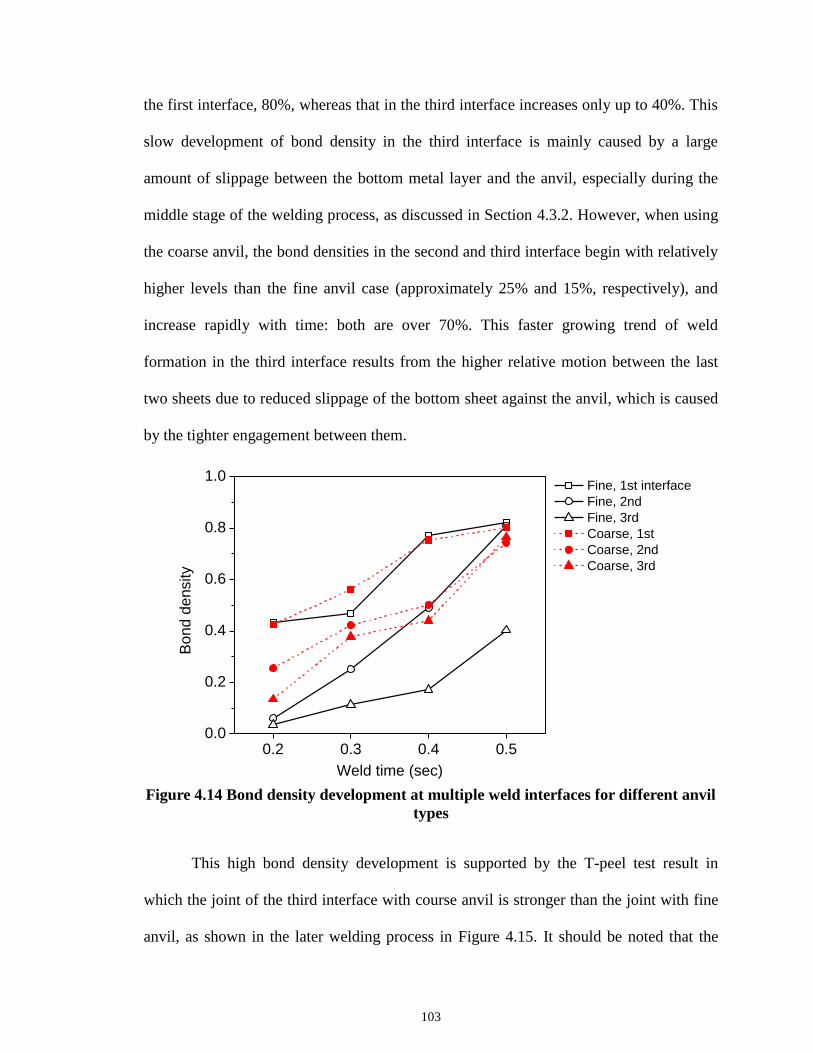
103
the first interface, 80%, whereas that in the third interface increases only up to 40%. This
slow development of bond density in the third interface is mainly caused by a large
amount of slippage between the bottom metal layer and the anvil, especially during the
middle stage of the welding process, as discussed in Section 4.3.2. However, when using
the coarse anvil, the bond densities in the second and third interface begin with relatively
higher levels than the fine anvil case (approximately 25% and 15%, respectively), and
increase rapidly with time: both are over 70%. This faster growing trend of weld
formation in the third interface results from the higher relative motion between the last
two sheets due to reduced slippage of the bottom sheet against the anvil, which is caused
by the tighter engagement between them.
Figure 4.14 Bond density development at multiple weld interfaces for different anvil
types
This high bond density development is supported by the T-peel test result in
which the joint of the third interface with course anvil is stronger than the joint with fine
anvil, as shown in the later welding process in Figure 4.15. It should be noted that the
0.2 0.3 0.4 0.50.0
0.2
0.4
0.6
0.8
1.0
Bo
nd
de
nsity
Weld time (sec)
Fine, 1st interface
Fine, 2nd
Fine, 3rd
Coarse, 1st
Coarse, 2nd
Coarse, 3rd

104
reason of higher performance of the third interface in most regions is a bigger weld
thickness or diffusion layer that may be formed between the thicker materials (total 1.2
mm) than other interfaces (total 0.4 mm). The effect of the ultrasonic weld thickness on
the ultrasonic weld strength can be further investigated.
(a)
(b)
Figure 4.15 Mechanical performance of multiple joints (three weld interfaces)
obtained by T-peel test for: (a) fine anvil type; and (b) coarse anvil type
0.1 0.2 0.3 0.4 0.5 0.60
40
80
120
160
200 1st interface
2nd interface
3rd interface
T-p
ee
l fo
rce
(N
)
Weld time (sec)
0.1 0.2 0.3 0.4 0.5 0.60
40
80
120
160
200
T-p
ee
l fo
rce
(N
)
Weld time (sec)

105
4.4 CONCLUSIONS
This chapter proposes a new methodology of high-speed imaging for
characterizing the ultrasonic metal welding process and reveals insights for optimum tool
design to improve the quality of multilayer joints. To analyze the weld formation in
multilayer ultrasonic welding, a high-speed camera is used to record the vibration of the
metal sheets. The vibrating profiles of the multiple layers and their relative motions are
obtained by high-speed images. The results from this high-speed imaging and the
subsequent microscopic analyses provide in-depth understanding of the propagation
mechanism in multilayer ultrasonic welding. Two anvil types are used to investigate the
impact of tool geometry on the weld formation in the multiple interfaces. This study
provides valuable insights on tool wear that can result from the extensive amount of
slippage during the ultrasonic welding process.
Notable findings are summarized as follows:
1) The vibration cycles of the multiple layers develop with increasing magnitude
in the initial period of the welding process. Each layer oscillates with different
amplitude but in phase, meaning that there are relative differences in
amplitude but no out-of-phase motions between the layers.
2) The maximum difference in vibration magnitude between the interfacing
layers occurs in the order of 1st, 2
nd, and 3
rd weld interface when using the fine
anvil, whereas the order is 1st, 3
rd, and 2
nd when using the coarse anvil.
3) The weld with the fine anvil propagates from top to bottom interface, i.e.,
“uni-directional”, while the weld with the coarse anvil is developed from both

106
ends, i.e., “bi-directional”. These different propagation mechanisms between
two anvil types are mainly caused by different amounts of slippage between
the bottom layer and the anvil due to the distinction in tool engagement with
materials.
4) The coarse anvil design performs better than the fine anvil in terms of higher
bond density and higher mechanical strength over the multiple weld interfaces.
5) The coarse anvil provides longer tool life since relative movement between
the 4th
layer and the tool is smaller compared with the anvil with fine
geometry.

107
REFERENCES
AmeTek (2013). Phantom V1610 Digital High-Speed Camera Data Sheet.
De Vries, E. (2004). Mechanics and Mechanisms of Ultrasonic Metal Welding.
Elangovan, S., Semeer, S. and Prakasan, K. (2009). "Temperature and Stress Distribution
in Ultrasonic Metal Welding—an Fea-Based Study." journal of materials
processing technology 209(3): 1143-1150.
Eriksson, I., Gren, P., Powell, J. and Kaplan, A. F. (2010). "New High-Speed
Photography Technique for Observation of Fluid Flow in Laser Welding." Optical
Engineering 49(10): 100503-100503-100503.
Eriksson, I., Powell, J. and Kaplan, A. F. (2010). Ultra High Speed Camera Investigations
of Laser Beam Welding. International Congress on Applications of Lasers &
Electro-Optics (ICALEO), Anaheim (CA), USA.
Gao, Y. and Doumanidis, C. (2002). "Mechanical Analysis of Ultrasonic Bonding for
Rapid Prototyping." Journal of Manufacturing Science and Engineering 124(2):
426-434.
Gibert, J. M., McCullough, D. T., Fadel, G. M., Martin, G. K. M. and Austin, E. M.
(2010). Stick-Slip Dynamics in Ultrasonic Consolidation. 2009 ASME
International Design Engineering Technical Conferences and Computers and
Information in Engineering Conference, DETC2009, August 30, 2009 - September
2, 2009, San Diego, CA, United states, American Society of Mechanical
Engineers.
Harthoorn, J. (1973). "Joint Formation in Ultrasonic Welding Compared with Fretting
Phenomena for Aluminium." Ultrasonics international 1973: 43-51.
Ji, H., Li, M., Kung, A. T., Wang, C. and Li, D. (2005). The Diffusion of Ni into Al Wire
at the Interface of Ultrasonic Wire Bond During High Temperature Storage.
Electronic Packaging Technology, 2005 6th International Conference on.
Joshi, K. C. (1971). "The Formation of Ultrasonic Bonds between Metals." Welding
Journal 50(12): 840-848.
Kang, B. S., Cai, W. and Tan, C. A. (2012). "Vibrational Energy Loss Analysis of
Battery Bus-Bar in Ultrasonic Welding." submitted to International Journal of
Mechanical Sciences.

108
Kang, B. S., Cai, W. and Tan, C. A. (2013). "Dynamic Response of Battery Tabs under
Ultrasonic Welding." accepted by Journal of Manufacturing Science &
Engineering.
Kim, T. H., Yum, J., Hu, S. J., Spicer, J. P. and Abell, J. A. (2011). "Process Robustness
of Single Lap Ultrasonic Welding of Thin, Dissimilar Materials." CIRP Annals -
Manufacturing Technology 60(1): 17-20.
Kreye, H. (1977). "Melting Phenomena in Solid State Welding Processes." Welding
Journal 56(5): 154-158.
Lee, D., Kannatey-Asibu, E. and Cai, W. (2012). "Ultrasonic Welding Simulations for
Multiple, Thin and Dissimilar Metals." submitted to ASME International
Symposium on Flexible Automation.
Lee, S. S., Kim, T. H., Hu, S. J., Cai, W. and Abell, J. A. (2010). "Joining Technologies
for Automotive Lithium-Ion Battery Manufacturing: A Review." ASME
Conference Proceedings 2010(49460): 541-549.
Lee, S. S., Kim, T. H., Hu, S. J., Cai, W., Abell, J. A. and Li, J. (2013). "Characterization
of Joint Quality in Ultrasonic Welding of Battery Tabs." Journal of
Manufacturing Science and Engineering 135(2): 021004.
Obielodan, J., Ceylan, A., Murr, L. and Stucker, B. (2010). "Multi-Material Bonding in
Ultrasonic Consolidation." Rapid Prototyping Journal 16(3): 180-188.
Ogawa, Y. (2011). "High Speed Imaging Technique Part 1 ‐ High Speed Imaging
of Arc Welding Phenomena." Science and Technology of Welding & Joining
16(1): 33-43.
Ram, G. D. J., Robinson, C., Yang, Y. and Stucker, B. (2007). "Use of Ultrasonic
Consolidation for Fabrication of Multi-Material Structures." Rapid Prototyping
Journal 13(4): 226-235.
Ram, G. D. J., Yang, Y. and Stucker, B. (2006). "Effect of Process Parameters on Bond
Formation During Ultrasonic Consolidation of Aluminum Alloy 3003." Journal
of Manufacturing Systems 25(3): 221-238.
Siddiq, A. and Ghassemieh, E. (2008). "Thermomechanical Analyses of Ultrasonic
Welding Process Using Thermal and Acoustic Softening Effects." Mechanics of
Materials 40(12): 982-1000.

109
Siddiq, A. and Ghassemieh, E. (2009). "Theoretical and Fe Analysis of Ultrasonic
Welding of Aluminum Alloy 3003." Journal of manufacturing science and
engineering 131(4): 041007.
Tucker, J. C. (2002). Ultrasonic Welding of Copper to Laminate Circuit Board.
Wen, Y. M., Huang, S. S. and Liu, G. X. (2011). "Testing and Analysis of High-Speed
Camera for Droplet Transition." Advanced Materials Research 271: 79-83.
Wen, Y. M., Huang, S. S. and Liu, G. X. (2012). "Testing and Analysis of High-Speed
Camera for Pulse Mig/Mag Welding Droplet Transition." Applied Mechanics and
Materials 103: 134-137.
Yang, Y., Ram, G. D. J. and Stucker, B. E. (2010). "An Analytical Energy Model for
Metal Foil Deposition in Ultrasonic Consolidation." Rapid Prototyping Journal
16(1): 20-28.
Zaal, J., van Driel, W., Kessels, F. and Zhang, G. (2008). Correlating Drop Impact
Simulations with Drop Impact Testing Using High-Speed Camera Measurements.
Thermal, Mechanical and Multi-Physics Simulation and Experiments in
Microelectronics and Micro-Systems, 2008. EuroSimE 2008. International
Conference on, IEEE.
Zhang, C. and Li, L. (2007). "Effect of Friction on Ultrasonic Consolidation." ASME
Conference Proceedings 2007(42908): 61-70.
Zhang, C. and Li, L. (2008). "A Friction-Based Finite Element Analysis of Ultrasonic
Consolidation." WELDING JOURNAL-NEW YORK- 87(7): 187.
Zhang, C. and Li, L. (2009). "A Coupled Thermal-Mechanical Analysis of Ultrasonic
Bonding Mechanism." Metallurgical and Materials Transactions B 40(2): 196-
207.
Zhang, C., Zhu, X. and Li, L. (2006). "A Study of Friction Behavior in Ultrasonic
Welding (Consolidation) of Aluminum." 87th FABTECH International and AWS
Welding Show Professional Program.

110
CHAPTER 5
CONCLUSIONS AND FUTURE WORK
5.1 CONCLUSIONS
Ultrasonic metal welding is believed to be most suitable for battery joining
because of its advantages on joining multiple thin layers of highly conductive and
dissimilar materials due to its solid-state characteristics. Since this joining technology is
newly adopted for battery pack manufacturing, there is a lack of widely accepted
standards on weld quality. In addition, limited understanding of the process hinders
achieving consistent product quality, which is critical for ensuring high power battery
packs. Thus, the goal of this thesis was to develop a methodology that can define the
ultrasonic weld quality using physical weld attributes, and to establish in-depth
understanding of the weld formation mechanisms in ultrasonic metal welding utilizing
sensor signals and high-speed images. This research has provided a comprehensive
characterization on the ultrasonic metal welding process and guidelines for systematic
quality definitions. Moreover, the scientific understanding obtained from this dissertation
will guide manufacturers in establishing a robust and reliable ultrasonic welding process
to achieve consistent quality.
The major findings of this dissertation can be summarized in three parts.

111
1) Characterization of joint quality in ultrasonic welding of battery tabs
A set of measurable weld attributes have been proposed to characterize
ultrasonically welded joints of copper and nickel plated copper. The joint
characteristics of different quality welds were investigated using those attributes and
the relationship between attributes and performance was quantitatively identified. The
main conclusions are summarized as follows:
The bonding strength of ultrasonically welded joints for copper and nickel-
plated copper results from the combined effect of metallurgical adhesion and
mechanical interlocking.
Different levels of weld quality (i.e., under, good, or over weld) are correlated
to the bond density and the post-weld thickness. The bond density increases as
the quality level changes from under, good to over weld whereas the post-
weld thickness decreases.
Material flow with extensive plastic deformation occurs at the metal surface in
contact with each horn tooth, and causes material thinning.
Material that has received high ultrasonic energy input show instant work
hardening due to the plastic deformation and then softening with continuous
temperature increase.
Various zones in an ultrasonic metal weld are distinguished by their
mechanical properties and micrographs. The sizes of these zones impact the
failure type during tensile testing and, eventually, weld quality.

112
2) Characterization of ultrasonic metal welding by correlating online sensor signals
with weld attributes
Power signal and horn displacements are thoroughly examined to understand the
physics behind the ultrasonic welding process. Several features from these two
signals are identified based on the physical understanding of signal variations under
abnormal process conditions such as surface contamination. These signal features are
then correlated to weld attributes measured from micrographs of cross-sectioned weld
samples. By relating those signal features to weld attributes, the joint quality can be
successfully predicted. The main conclusions are summarized as follows.
Power signal provides useful information on the change of mechanical
resistance at the weld interface whereas displacement signal reflects the
pattern for material deformation.
The power and displacement signals halfway through the process provide
critical information on the abnormal process conditions.
The energy used and the indentation depth for the whole welding process
indicate whether weld formation at the interface is completed.
The relationships between weld attributes and several signal features such as
Etotal, Emid, Dtotal, and Dmid provide physical understanding on the impact of
process conditions on the weld quality.

113
3) Analysis of weld formation in multilayer ultrasonic metal welding using high-speed
images
A new methodology of high-speed imaging is developed for characterizing the
ultrasonic metal welding process and reveals insights for optimum tool design to
improve the quality of multilayer joints. The vibrating profiles of the multiple layers
and their relative motions are obtained from high-speed images. Two anvil types are
used to investigate the impact of tool geometry on weld formation in the multiple
interfaces. The results from this high-speed imaging and the subsequent microscopic
analyses provide in-depth understanding on the propagation mechanism in multilayer
ultrasonic welding. The main conclusions are summarized as follows.
The vibration cycles of the multiple layers are developed with increasing
amplitudes in the initial period of the welding process.
The maximum difference in vibration magnitude between the interfacing
layers occurs in the order of 1st, 2
nd, and 3
rd weld interface when using the fine
anvil, whereas the order is 1st, 3
rd, and 2
nd when using the coarse anvil.
The weld with the fine anvil propagates from top to bottom interface, i.e.,
“uni-directional”, while the weld with the coarse anvil is developed from both
ends, i.e., “bi-directional”.
The coarse anvil design performs better than the fine anvil in terms of higher
bond density and higher mechanical strength over the multiple weld interfaces.
The coarse anvil provides longer tool life since relative movements between
the 4th
layer and the tool is smaller compared with the anvil with fine
geometry.

114
5.2 FUTURE WORK
Based upon the findings of this dissertation, the future work may include the
following directions:
1) Performance modeling of ultrasonic metal welds
A sophisticated finite element model of joint performance can be developed by
incorporating weld attributes that determine the weld quality. A design of experiment
for the simulations can be performed to identify critical weld attributes affecting the
joint performance. This will establish complete relationships between weld process,
attributes, and performances.
2) Ultrasonic welding of copper and aluminum
Dissimilar welding of copper and aluminum is another challenging task in battery
manufacturing, due to different material properties including surface hardness (pure
aluminum: 23~28 HV of Vickers [Murr et al. 1997]; pure copper: 55~60 HV [Kaneko
et al. 2005]) . In addition, pure aluminum is very prone to sticking on the weld tool
[Bloss 2007]. By using the same methodology provided in this dissertation, a
comprehensive characterization on the ultrasonic welding of copper and aluminum
will maximize the robustness and reliability of the process.
3) Development of real-time process control
In-depth understanding of the ultrasonic welding of multiple metal sheets is
established by phenomenological observation on the process. From this observation,
possible tool wear is seen due to extensive slippage between the tool and workpiece.

115
A real-time control of process variables, such as pressure and vibration amplitude,
may reduce the slippage and provide longer tool life, resulting in cost saving.
REFERENCES
Bloss, M. C. (2007). Ultrasonic Metal Welding: The Weldability of Stainless Steel,
Titanium, and Nickel-Based Superalloys, Ohio State University.
Kaneko, Y., Mizuta, Y., Nishijima, Y. and Hashimoto, S. (2005). "Vickers Hardness and
Deformation of Ni/Cu Nano-Multilayers Electrodeposited on Copper Substrates."
Journal of Materials Science 40(12): 3231-3236.
Murr, L., Liu, G. and McClure, J. (1997). "Dynamic Recrystallization in Friction-Stir
Welding of Aluminium Alloy 1100." Journal of materials science letters 16(22):
1801-1803.