Up-to-date price list:www.automationdirect.com/pricelist
FREE Technical Support:www.automationdirect.com/support
FREE Videos:www.automationdirect.com/videos
FREE Documentation:www.automationdirect.com/documentation
FREE CAD drawings:www.automationdirect.com/cad
Power Transmission Overview
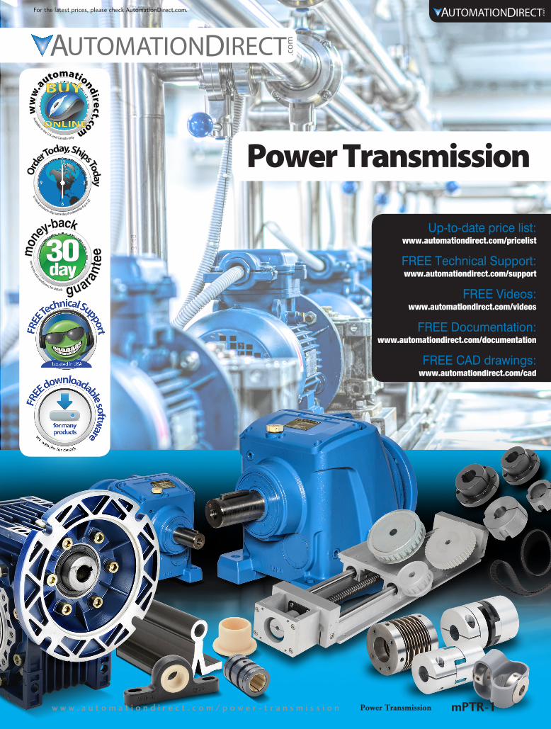
Power Transmissionw w w . a u t o m a t i o n d i r e c t . c o m / p o w e r - t r a n s m i s s i o n mPTR-1
For the latest prices, please check AutomationDirect.com.

AutomationDirect’s IronHorse gearboxes are designed for use with C-face electric motors to reduce output speed, increase torque, change drive direction, or run two loads from one motor. Multiple frame sizes and gear ratios in right hand, left hand and dual shaft output configurations are offered and optional mounting bases are also available for ease of instal-
lation. These units are manufactured in an ISO9001 certified plant by one of the leading worm gearbox manufacturers in the world today. Strict adherence to and compliance with the toughest international and U.S. testing standards and manu-facturing procedures assure you the highest quality mechanical power transmission products.
Radiused mounting holes
Aluminum bronze casting main gear is much harder than the normally used phosphor bronze
Single output cover design provides precise centering of gear for lower noise levels and higher overall gear efficiencies.
1045 Carbon Steel Shaft
Factory filled with premium Mobil SHC634 synthetic lubricant.
Tapered roller bearings on worm shaft - heavy duty ball bearings on output shaft
Embedded Oil Seals prevent leakage on both ends
Single-piece, alloy steel input worm shaft High lead angle worm is case-hardened, ground and polished for enhanced efficiency and noise reduction
One-piece housing available in cast iron or aluminum
PricesStarting at
>$97.00<!
Cast Iron Worm Gearboxes (Speed Reducers) • Four output types: Dual Shaft, Right Hand Shaft, Left Hand Shaft and
Hollow Shaft
• Five frame sizes: 1.75”, 2.06”, 2.37”, 2.62”, 3.25”
• Six ratios: 5:1, 10:1, 15:1, 20:1, 30:1, 40:1, 60:1
• These gearboxes utilize C-face mounting interfaces for C-face motors
• Worm gear reducer mounting bases are also available for ease of installation
Aluminum Worm Gearboxes (Speed Reducers)• Hollow shaft output
• Five frame sizes: 30, 40, 50, 63, 75 mm
• Gear ratios: 10:1 to 100:1 (in most sizes)
• Input faces: 56C, 145TC, 182/4TC
• Mounting flanges, output shafts, torque arms and covers are also available to allow many mounting and configuration options
IronHorse® General Purpose Gearboxes
Affordable Power Transmission
1 - 8 0 0 - 6 3 3 - 0 4 0 5Power TransmissionmPTR-2
For the latest prices, please check AutomationDirect.com.

Compatible with our Ironhorse MotorsThe worm, helical and shaft mount gearboxes were selected to match up with our IronHorse motors. Most worm gearbox models are equipped with NEMA 56C motor inputs, while the helical gearboxes are available in several additional NEMA frame size input configurations. Shaft mount gear-boxes are connected to the motor with v-belts and sheaves (not sold by Automation Direct). Our complete line of MTR general purpose motors and many of our inverter duty Marathon motors will easily bolt to these boxes. Please see the complete technical specifications to choose the correct gearbox for your application.
Affordable Power Transmission
Cast Iron Helical Gearboxes • Five frame sizes: 37, 47, 67, 77, 87 mm
• Gear ratios: 5:1, 10:1, 15:1, 20:1, 30:1, 40:1, 60:1
• Input faces: 56C, 145TC, 182/4TC, 213/5TC, 254/6TC
• Drop-in replacement for most popular European inline gear reducers
IronHorse®
Shaft Mount GearboxesDesigned to mount to the driven shaft of a machine, these mechanical drive components drive a load at a reduced ratio of the motor speed. The output torque is increased by the same ratio, while the horsepower remains the same (less efficiency losses). These are drop-in replacements for other major brand gearboxes (Dodge™, Nord ™, etc). Torque Arms are included with each gearbox. Optional accessories include: bushings for various shaft sizes, stan-dardized shafts for use with screw conveyors, motor mounts, belt guards, screw conveyor mounting flanges and back-stop (anti-reversing) assemblies. V-belts and sheaves are typically used to connect the motor shaft to the input shaft of these gearboxes AND to fine tune the final gear ratio, but are not sold by Automation Direct.
• 9:1, 15:1 and 25:1 ratios
• Frame sizes 2 to 5
• Industrial grade all cast-iron housings protect gearing for life
• Extended gear centers and tooth contact
• Metal reinforced double lip, spring loaded oil seals
• Dimensional drop-in for all major makes
• Torque arm included
Ironhorse AC motor (sold separately) Optional Belt Guard
(shown in cut-a-way for visual clarity)
Optional motor mount (allows belt tensioning)
Shaft Bushings (sold separately in
a range of sizes)
Torque Arm(included)
Pulleys and Sheaves (not sold by AutomationDirect)
Power Transmissionw w w . a u t o m a t i o n d i r e c t . c o m / p o w e r - t r a n s m i s s i o n mPTR-3
For the latest prices, please check AutomationDirect.com.
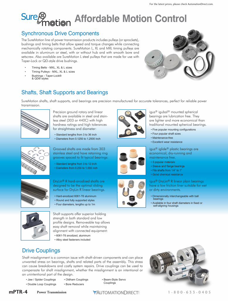
Synchronous Drive ComponentsThe SureMotion line of power transmission products includes pulleys (or sprockets), bushings and timing belts that allow speed and torque changes while connecting mechanically rotating components. SureMotion L, XL and MXL timing pulleys are available in aluminum or steel, with or without hub and with smooth bore and setscrew. Also available are SureMotion L steel pulleys that are made for use with Taper-Lock or QD-style drive bushings.
• Timing Belts - MXL, XL & L sizes• Timing Pulleys - MXL, XL & L sizes • Bushings - Taper-Lock®
& QD® styles
Drive CouplingsShaft misalignment is a common issue with shaft-driven components and can place unwanted stress on bearings, shafts and related parts of the assembly. This stress can cause breakdowns and costly system repairs. Drive couplings can be used to compensate for shaft misalignment, whether the misalignment is an intentional or an unintentional part of the design.
Shafts, Shaft Supports and Bearings
Affordable Motion Control
SureMotion shafts, shaft supports, and bearings are precision manufactured for accurate tolerances, perfect for reliable power transmission.
Precision ground rotary and linear shafts are available in steel and stain-less steel (303 or 440C) with high hardness ratings and high tolerances for straightness and diameter:
• Standard lengths from 3 to 36 inch• Diameters from 0.1250 to 1.2500 inch
Grooved shafts are made from 303 stainless steel and have retaining ring grooves spaced to fit typical bearings:
• Standard lengths from 3 to 12 inch• Diameters from 0.250 to 1.000 inch
DryLin® R hard-anodized shafts are designed to be the optimal sliding surface for DryLin R linear bearings.
• Hard-anodized 6061-T6 aluminum• Round and fully supported styles• Four diameters, lengths up to 1m
Shaft supports offer superior holding strength in both standard and low profile designs. Removeable top allows easy shaft removal while maintaining alignment with connected equipment:• 6061-T6 anodized, aluminum• Alloy steel fasteners included
• Jaw / Spider Couplings
• Double Loop Couplings
• Oldham Couplings
• Bore Reducers
• Beam-Style Servo Couplings
igus® igubal® mounted spherical bearings are lubrication free. They are lighter and more economical than traditional mounted spherical bearings.• Five popular mounting configurations• Four popular shaft sizes• Maintenance-free• Excellent wear resistance
igus® iglide® plastic bearings are economical, dry-running and maintenance free.• 3 popular materials• Sleeve and flange bearings• Fits shafts from 1/4” to 1”• Good chemical resistance
igus® DryLin® R linear plain bearings have a low friction liner suitable for wet or dirty environments.
• Dimensionally interchangeable with ball bearings• Available in four shaft diameters in fixed or self-aligning housings
1 - 8 0 0 - 6 3 3 - 0 4 0 5Power TransmissionmPTR-4
For the latest prices, please check AutomationDirect.com.
IronHorse® Cast-Iron Worm Gearboxes
Gearbox OverviewGearboxes, also known as enclosed gear drives or speed reducers, are mechanical drive components that can control a load at a reduced fixed ratio of the motor speed. The output torque is also increased by the same ratio, while the horsepower remains the same (less efficiency losses.) For example, a 10:1 ratio gearbox outputs approximately the same motor output horsepower, motor speed divided by 10, and motor torque multiplied by 10.
Worm gearboxes contain a worm (gear type) on the input shaft, and a mating gear on the output shaft. Worm gear-boxes also change the drive direction by 90°.
IronHorse worm gearboxes are manufactured in an ISO9001 certified plant by one of the leading gearbox manufacturers in the world today. Only the highest quality materials are tested, certified, and used in the manufac-turing process. Strict adherence to and compliance with the toughest international and U.S. testing standards and manufacturing procedures assure you the highest quality products.
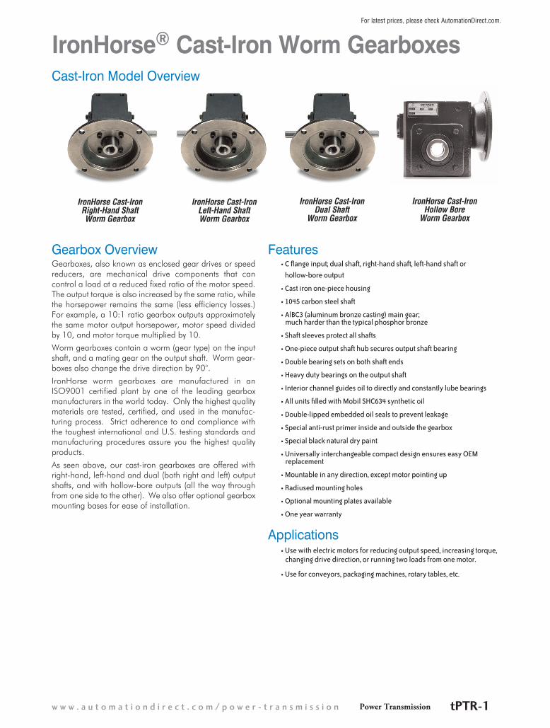
As seen above, our cast-iron gearboxes are offered with right-hand, left-hand and dual (both right and left) output shafts, and with hollow-bore outputs (all the way through from one side to the other). We also offer optional gearbox mounting bases for ease of installation.
IronHorse Cast-Iron Right-Hand Shaft Worm Gearbox
Features• C flange input; dual shaft, right-hand shaft, left-hand shaft or
hollow-bore output
• Cast iron one-piece housing
• 1045 carbon steel shaft
• AlBC3 (aluminum bronze casting) main gear; much harder than the typical phosphor bronze
• Shaft sleeves protect all shafts
• One-piece output shaft hub secures output shaft bearing
• Double bearing sets on both shaft ends
• Heavy duty bearings on the output shaft
• Interior channel guides oil to directly and constantly lube bearings
• All units filled with Mobil SHC634 synthetic oil
• Double-lipped embedded oil seals to prevent leakage
• Special anti-rust primer inside and outside the gearbox
• Special black natural dry paint
• Universally interchangeable compact design ensures easy OEM replacement
• Mountable in any direction, except motor pointing up
• Radiused mounting holes
• Optional mounting plates available
• One year warranty
Applications• Use with electric motors for reducing output speed, increasing torque, changing drive direction, or running two loads from one motor.
• Use for conveyors, packaging machines, rotary tables, etc.
IronHorse Cast-Iron Dual Shaft
Worm Gearbox
IronHorse Cast-Iron Hollow Bore
Worm Gearbox
IronHorse Cast-Iron Left-Hand Shaft Worm Gearbox
Cast-Iron Model Overview
Power Transmissionw w w . a u t o m a t i o n d i r e c t . c o m / p o w e r - t r a n s m i s s i o n tPTR-1
For latest prices, please check AutomationDirect.com.

IronHorse® Cast-Iron Worm GearboxesSpecifications
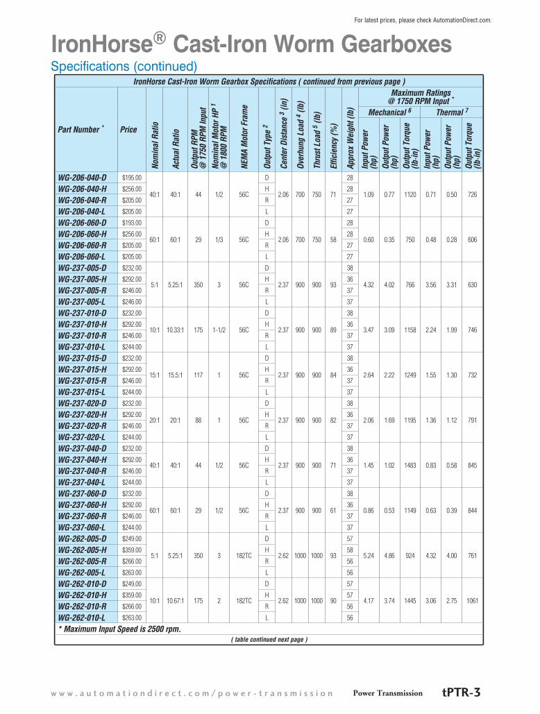
IronHorse Cast-Iron Worm Gearbox Specifications
Part Number * Price
Nom
inal
Rat
io
Actu
al R
atio
Outp
ut R
PM
@ 1
750
RPM
Inpu
tNo
min
al M
otor
HP
1 @
180
0 RP
M
NEM
A M
otor
Fra
me
Outp
ut T
ype
2
Cent
er D
ista
nce
3 (in
)
Over
hung
Loa
d 4 (
lb)
Thru
st L
oad
5 (lb
)
Effic
ienc
y (%
)
Appr
ox W
eigh
t (lb
)
Maximum Ratings @ 1750 RPM Input *
Mechanical 6 Thermal 7
Inpu
t Pow
er
(hp)
Outp
ut P
ower
(h
p)Ou
tput
Tor
que
(lb·in
)In
put P
ower
(h
p)Ou
tput
Pow
er
(hp)
Outp
ut T
orqu
e (lb
·in)
WG-175-005-D $162.00
5:1 5.25:1 350 1-1/2 56C
D
1.75 650 550
93
23
2.83 2.62 499 2.28 2.11 402WG-175-005-H $200.00 H 23
WG-175-005-R $162.00 R 22
WG-175-005-L $161.00 L 22
WG-175-010-D $162.00
10:1 10.33:1 175 1 56C
D
88
23
1.57 1.38 515 1.36 1.19 445WG-175-010-H $200.00 H 23
WG-175-010-R $162.00 R 22
WG-175-010-L $161.00 L 22
WG-175-015-D $162.00
15:1 14.5:1 117 3/4 56C
D
85
23
1.24 1.06 554 1.13 0.96 506WG-175-015-H $200.00 H 23
WG-175-015-R $162.00 R 22
WG-175-015-L $161.00 L 22
WG-175-020-D $162.00
20:1 19.5:1 88 3/4 56C
D
83
23
1.26 1.04 737 0.98 0.81 572WG-175-020-H $200.00 H 23
WG-175-020-R $162.00 R 22
WG-175-020-L $161.00 L 22
WG-175-040-D $162.00
40:1 40:1 44 1/3 56C
D
62
23
0.79 0.49 714 0.45 0.28 404WG-175-040-H $212.00 H 23
WG-175-040-R $162.00 R 22
WG-175-040-L $161.00 L 22
WG-175-060-D $162.00
60:1 60:1 29 1/4 56C
D
52
23
0.38 0.20 433 0.35 0.19 404WG-175-060-H $212.00 H 23
WG-175-060-R $162.00 R 22
WG-175-060-L $161.00 L 22
WG-206-005-D $205.00
5:1 5.75:1 350 2 56C
D
2.06 700 750
92
28
3.62 3.33 925 2.57 2.36 657WG-206-005-H $256.00 H 28
WG-206-005-R $205.00 R 27
WG-206-005-L $203.00 L 27
WG-206-010-D $205.00
10:1 10.33:1 175 1-1/2 56C
D
90
28
2.77 2.50 935 2.10 1.89 708WG-206-010-H $256.00 H 28
WG-206-010-R $205.00 R 27
WG-206-010-L $203.00 L 27
WG-206-015-D $205.00
15:1 15.5:1 117 1 56C
D
85
28
2.09 1.78 1002 1.40 1.20 673WG-206-015-H $256.00 H 28
WG-206-015-R $205.00 R 27
WG-206-015-L $203.00 L 27
WG-206-020-D $193.00
20:1 19.5:1 88 1 56C
D
82
28
1.57 1.29 914 1.17 0.96 681WG-206-020-H $256.00 H 28
WG-206-020-R $205.00 R 27
WG-206-020-L $205.00 L 27
* Maximum Input Speed is 2500 rpm.( table continued next page )
1 - 8 0 0 - 6 3 3 - 0 4 0 5Power TransmissiontPTR-2
For latest prices, please check AutomationDirect.com.
Specifications (continued)IronHorse® Cast-Iron Worm Gearboxes
IronHorse Cast-Iron Worm Gearbox Specifications ( continued from previous page )
Part Number * Price
Nom
inal
Rat
io
Actu
al R
atio
Outp
ut R
PM
@ 1
750
RPM
Inpu
tNo
min
al M
otor
HP
1 @
180
0 RP
M
NEM
A M
otor
Fra
me
Outp
ut T
ype
2
Cent
er D
ista
nce
3 (in
)
Over
hung
Loa
d 4 (
lb)
Thru
st L
oad
5 (lb
)
Effic
ienc
y (%
)
Appr
ox W
eigh
t (lb
)
Maximum Ratings @ 1750 RPM Input *
Mechanical 6 Thermal 7
Inpu
t Pow
er
(hp)
Outp
ut P
ower
(h
p)Ou
tput
Tor
que
(lb·in
)In
put P
ower
(h
p)Ou
tput
Pow
er
(hp)
Outp
ut T
orqu
e (lb
·in)
WG-206-040-D $195.00
40:1 40:1 44 1/2 56C
D
2.06 700 750 71
28
1.09 0.77 1120 0.71 0.50 726WG-206-040-H $256.00 H 28
WG-206-040-R $205.00 R 27
WG-206-040-L $205.00 L 27
WG-206-060-D $193.00
60:1 60:1 29 1/3 56C
D
2.06 700 750 58
28
0.60 0.35 750 0.48 0.28 606WG-206-060-H $256.00 H 28
WG-206-060-R $205.00 R 27
WG-206-060-L $205.00 L 27
WG-237-005-D $232.00
5:1 5.25:1 350 3 56C
D
2.37 900 900 93
38
4.32 4.02 766 3.56 3.31 630WG-237-005-H $292.00 H 36
WG-237-005-R $246.00 R 37
WG-237-005-L $246.00 L 37
WG-237-010-D $232.00
10:1 10.33:1 175 1-1/2 56C
D
2.37 900 900 89
38
3.47 3.09 1158 2.24 1.99 746WG-237-010-H $292.00 H 36
WG-237-010-R $246.00 R 37
WG-237-010-L $244.00 L 37
WG-237-015-D $232.00
15:1 15.5:1 117 1 56C
D
2.37 900 900 84
38
2.64 2.22 1249 1.55 1.30 732WG-237-015-H $292.00 H 36
WG-237-015-R $246.00 R 37
WG-237-015-L $244.00 L 37
WG-237-020-D $232.00
20:1 20:1 88 1 56C
D
2.37 900 900 82
38
2.06 1.69 1195 1.36 1.12 791WG-237-020-H $292.00 H 36
WG-237-020-R $246.00 R 37
WG-237-020-L $244.00 L 37
WG-237-040-D $232.00
40:1 40:1 44 1/2 56C
D
2.37 900 900 71
38
1.45 1.02 1483 0.83 0.58 845WG-237-040-H $292.00 H 36
WG-237-040-R $246.00 R 37
WG-237-040-L $244.00 L 37
WG-237-060-D $232.00
60:1 60:1 29 1/2 56C
D
2.37 900 900 61
38
0.86 0.53 1149 0.63 0.39 844WG-237-060-H $292.00 H 36
WG-237-060-R $246.00 R 37
WG-237-060-L $244.00 L 37
WG-262-005-D $249.00
5:1 5.25:1 350 3 182TC
D
2.62 1000 1000 93
57
5.24 4.86 924 4.32 4.00 761WG-262-005-H $359.00 H 58
WG-262-005-R $266.00 R 56
WG-262-005-L $263.00 L 56
WG-262-010-D $249.00
10:1 10.67:1 175 2 182TC
D
2.62 1000 1000 90
57
4.17 3.74 1445 3.06 2.75 1061WG-262-010-H $359.00 H 57
WG-262-010-R $266.00 R 56
WG-262-010-L $263.00 L 56
* Maximum Input Speed is 2500 rpm.( table continued next page )
Power Transmissionw w w . a u t o m a t i o n d i r e c t . c o m / p o w e r - t r a n s m i s s i o n tPTR-3
For latest prices, please check AutomationDirect.com.

Specifications (continued)IronHorse® Cast-Iron Worm Gearboxes
IronHorse Cast-Iron Worm Gearbox Specifications ( continued from previous page )
Part Number * Price
Nom
inal
Rat
io
Actu
al R
atio
Outp
ut R
PM
@ 1
750
RPM
Inpu
tNo
min
al M
otor
HP
1 @
180
0 RP
M
NEM
A M
otor
Fra
me
Outp
ut T
ype
2
Cent
er D
ista
nce
3 (in
)
Over
hung
Loa
d 4 (
lb)
Thru
st L
oad
5 (lb
)
Effic
ienc
y (%
)
Appr
ox W
eigh
t (lb
)
Maximum Ratings @ 1750 RPM Input *
Mechanical 6 Thermal 7
Inpu
t Pow
er
(hp)
Outp
ut P
ower
(h
p)Ou
tput
Tor
que
(lb·in
)In
put P
ower
(h
p)Ou
tput
Pow
er
(hp)
Outp
ut T
orqu
e (lb
·in)
WG-262-015-D $249.00
15:1 15.5:1 117 2 56C
D
2.62 1000 1000 87
50
3.22 2.81 1577 2.47 2.16 1212WG-262-015-H $359.00 H 50
WG-262-015-R $266.00 R 49
WG-262-015-L $263.00 L 49
WG-262-020-D $249.00
20:1 19.5:1 88 1-1/2 56C
D
2.62 1000 1000 83
50
2.67 2.21 1563 1.84 1.53 1078WG-262-020-H $359.00 H 50
WG-262-020-R $266.00 R 49
WG-262-020-L $263.00 L 49
WG-262-040-D $249.00
40:1 40:1 44 3/4 56C
D
2.62 1000 1000 72
50
1.85 1.32 1919 1.11 0.80 1153WG-262-040-H $359.00 H 50
WG-262-040-R $266.00 R 49
WG-262-040-L $263.00 L 49
WG-262-060-D $249.00
60:1 60:1 29 3/4 56C
D
2.62 1000 1000 66
50
1.16 0.77 1670 0.94 0.62 1346WG-262-060-H $359.00 H 51
WG-262-060-R $266.00 R 49
WG-262-060-L $263.00 L 49
WG-325-010-DC $392.00
10:1 10.33:1 175 3 182/4TC
D
3.25 1200 1100 90
91
7.19 6.46 2419 4.63 4.16 1558WG-325-010-HC $515.00 H 90
WG-325-010-LC $392.00 L 90
WG-325-010-RC $392.00 R 90
WG-325-015-DC $392.00
15:1 15.5:1 117 5 182/4TC
D
3.25 1200 1100 85
91
5.45 4.65 2611 3.19 2.72 1527WG-325-015-HC $515.00 H 90
WG-325-015-LC $392.00 L 90
WG-325-015-RC $392.00 R 90
WG-325-020-DC $392.00
20:1 19.5:1 88 3 182TC
D
3.25 1200 1100 86
91
4.74 4.07 2875 3.31 2.85 2011WG-325-020-HC $515.00 H 90
WG-325-020-LC $392.00 L 90
WG-325-020-RC $392.00 R 90
WG-325-030-DA $392.00
30:1 30:1 58
2
56C D
3.25 1200 1100 77
88
3.66 2.80 3045 2.00 1.53 1661
WG-325-030-DB $392.00 145TC D 88
WG-325-030-HA $515.00 56C H 87
WG-325-030-HB $515.00 145TC H 87
WG-325-030-LA $392.00 56C L 87
WG-325-030-LB $392.00 145TC L 87
WG-325-030-LC $392.00 3 182TC L 87
WG-325-030-RA $392.002
56C R 87
WG-325-030-RB $392.00 145TC R 87
WG-325-030-RC $392.00 3 182TC R 87
* Maximum Input Speed is 2500 rpm.( table continued next page )
1 - 8 0 0 - 6 3 3 - 0 4 0 5Power TransmissiontPTR-4
For latest prices, please check AutomationDirect.com.
Specifications (continued)IronHorse® Cast-Iron Worm Gearboxes
IronHorse Cast-Iron Worm Gearbox Specifications ( continued from previous page )
Part Number * Price
Nom
inal
Rat
io
Actu
al R
atio
Outp
ut R
PM
@ 1
750
RPM
Inpu
tNo
min
al M
otor
HP
1 @
180
0 RP
M
NEM
A M
otor
Fra
me
Outp
ut T
ype
2
Cent
er D
ista
nce
3 (in
)
Over
hung
Loa
d 4 (
lb)
Thru
st L
oad
5 (lb
)
Effic
ienc
y (%
)
Appr
ox W
eigh
t (lb
)
Maximum Ratings @ 1750 RPM Input *
Mechanical 6 Thermal 7
Inpu
t Pow
er
(hp)
Outp
ut P
ower
(h
p)Ou
tput
Tor
que
(lb·in
)In
put P
ower
(h
p)Ou
tput
Pow
er
(hp)
Outp
ut T
orqu
e (lb
·in)
WG-325-040-DA $392.00
40:1 40:1 44 1-1/2
56C D
3.25 1200 1100 76
88
3.35 2.55 3692 1.96 1.49 2156
WG-325-040-DB $392.00 145TC D 88
WG-325-040-HA $515.00 56C H 87
WG-325-040-HB $515.00 145TC H 87
WG-325-040-LA $392.00 56C L 87
WG-325-040-LB $392.00 145TC L 87
WG-325-040-RA $392.00 56C R 87
WG-325-040-RB $392.00 145TC R 87
WG-325-060-DA $392.00
60:1 60:1 29 1-1/2
56C D
3.25 1200 1100 71
88
2.03 1.44 3127 1.61 1.14 2476
WG-325-060-DB $392.00 145TC D 88
WG-325-060-HA $515.00 56C H 87
WG-325-060-HB $515.00 145TC H 87
WG-325-060-LA $392.00 56C L 87
WG-325-060-LB $392.00 145TC L 87
WG-325-060-RA $392.00 56C R 87
WG-325-060-RB $392.00 145TC R 87
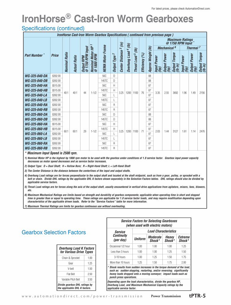
* Maximum Input Speed is 2500 rpm.1) Nominal Motor HP is the highest hp 1800 rpm motor to be used with the gearbox under conditions of 1.0 service factor. Gearbox input power capacity
decreases as motor speed decreases and as service factor increases.
2) Output Type: D = Dual Shaft; H = Hollow Bore; R = Right-Hand Shaft; L = Left-Hand Shaft
3) The Center Distance is the distance between the centerlines of the input and output shafts.
4) Overhung Load ratings are for forces perpendicular to the output shaft and located at the shaft midpoint, such as from a gear, pulley, or sprocket with a belt or chain. Divide OHL ratings by the applicable OHL K factors shown separately in the Selection Factors tables. OHL ratings should also be divided by applicable service factors.
5) Thrust Load ratings are for forces along the axis of the output shaft, usually encountered in vertical-drive applications from agitators, mixers, fans, blowers, etc.
6) Maximum Mechanical Ratings are limits based on strength and durability of gearbox components; applicable when operating time is short and stopped time is greater than or equal to operating time. These ratings are applicable for 1.0 service factor loads, and may require modification depending upon characteristics of the applicable driven loads. Refer to the “Service Factors” table for more information.
7) Maximum Thermal Ratings are limits for gearbox continuous use without overheating.
Gearbox Selection Factors
Service Factors for Selecting Gearboxes(when used with electric motors)
Service Continuity (per day)
Load Characteristics
Uniform Moderate Shock*
Heavy Shock*
Extreme Shock*
Occasional 1/2 hour 1.00 1.00 1.00 1.25
Less than 3 hours 1.00 1.00 1.25 1.50
3-10 hours 1.00 1.25 1.50 1.75
More than 10 hours 1.25 1.50 1.75 2.00
* Shock results from sudden increases in the torque demand of the load, such as: sudden stopping, restarting, and/or reversing; significantly heavy loads dropped onto a moving conveyor; impact loads such as punch press operations.
Depending upon the load characteristics, divide the gearbox HP, Overhung Load, and Maximum Mechanical Capacity ratings by the applicable service factor.
Overhung Load K Factors for Various Drive Types
Chain & Sprocket 1.00
Gear 1.25
V-belt 1.50
Flat Belt 2.50
Variable Pitch Belt 3.50
Divide gearbox OHL ratings by the applicable OHL K factors.
Power Transmissionw w w . a u t o m a t i o n d i r e c t . c o m / p o w e r - t r a n s m i s s i o n tPTR-5
For latest prices, please check AutomationDirect.com.

Dimensions (inches) – IronHorse Cast-Iron Worm Gearboxes – Solid-Shaft Outputs
Part Number
Fram
e
A AB AC BB BD BE CC F H LL Z (UNC)
Flange Input Shaft Output Shaft
LA LC Z1 W X L1 N S X2
WG-175-xxx-D/L/R56C
7.29 4.035 5.06 4.311 3.56 2.75 1.75 4.188 5.75 2.062 5/16-18
5.875 6.496 0.433 5/8 3/16
1 1.781 7/8 3/16
WG-206-xxx-D/L/R 7.95 4.37 5.75 4.69 3.82 2.88 2.062 5 6.38 2.281
3/8-16
1.25 2.09 1
1/4
WG-237-xxx-D/L/R 8.71 4.705 6.38 5.087 4.06 2.88 2.375 5 6.94 2.5 1.25 2.37
1-1/8
WG-262-005-D/L/R182TC 10.57 6.24
7.17 5.63 4.69 3.375 2.625 6.375 8 2.938
7.25 9 0.551 1-1/8 1/4
2 2.626
WG-262-010-D/L/RWG-262-015-D/L/R
56C 9.41 5.059 5.875 6.496 0.433 5/8 3/16WG-262-020-D/L/RWG-262-040-D/L/RWG-262-060-D/L/RWG-325-010-xC
182/4TC12.60 7.24
9.02 7.06 5.75 4.00 3.25 7.50 9.38 3.50 7/16-14
7.25 9.00 0.55 1-1/8 1/4
2.44 3.25 1-3/8 5/16
WG-325-015-xCWG-325-020-xC 182TC
WG-325-030-xA 56C11.42 6.06 5.875 6.50 0.41
5/83/16
WG-325-030-xB 145TC 7/8
WG-325-030-xC 182TC 12.60 7.24 7.25 9.00 0.55 1-1/8 1/4
WG-325-040-xA 56C
11.42 6.06 5.875 6.50 0.41
5/8
3/16WG-325-040-xB 145TC 7/8
WG-325-060-xA 56C 5/8
WG-325-060-xB 145TC 7/8
Dual-shaft output gearboxes have BB, L1, N, S, X2 dimensions on both sides. Left-hand shaft gearboxes have output shafts only on the left side, as viewed looking into the input shaft (dimensions BB, L1, N, S, X2 ). Right-hand shaft gearboxes have output shafts only on the right side, as viewed looking into the input shaft (dimensions BB, L1, N, S, X2). See our website: www.AutomationDirect.com for complete engineering drawings.
IronHorse® Cast-Iron Worm Gearboxes
F/2
CC
AB
A
BE
ØS
ØLA
ØS Ø
LA
ØLC
L1L1
N N
BD
2x4-Z
F
AC
4-Z1
LL
H
BB BB
Rear View
X
W
X2
Output Shaft View
Left View
Input Shaft View
Gearbox Dimensions – Cast-Iron Solid-Shaft Output Gearboxes
1 - 8 0 0 - 6 3 3 - 0 4 0 5Power TransmissiontPTR-6
For latest prices, please check AutomationDirect.com.
FAC
H
F/2
LLC
C
AB2x4-Z
BE
BD
ØS
4-Z1
BB BB
ØLA
T
U
2x3-Z2ØLC
A
Output Shaft View
Rear View Left View
W
X
Input Shaft View
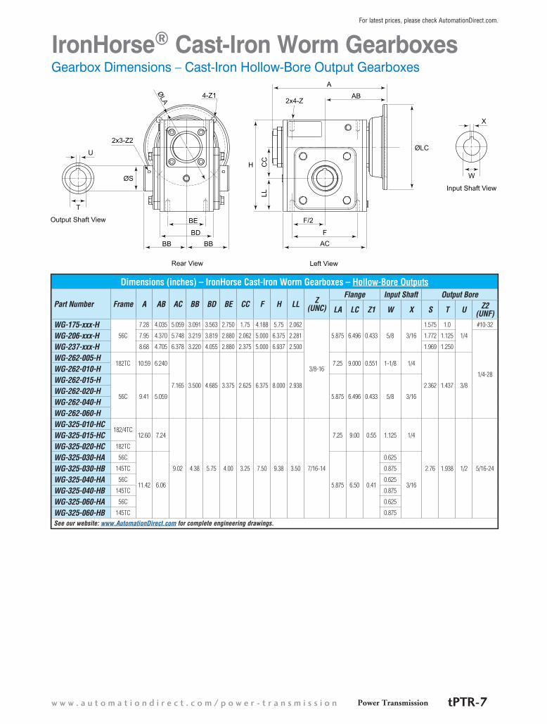
IronHorse® Cast-Iron Worm GearboxesGearbox Dimensions – Cast-Iron Hollow-Bore Output Gearboxes
Dimensions (inches) – IronHorse Cast-Iron Worm Gearboxes – Hollow-Bore Outputs
Part Number Frame A AB AC BB BD BE CC F H LL Z (UNC)
Flange Input Shaft Output Bore
LA LC Z1 W X S T U Z2 (UNF)
WG-175-xxx-H56C
7.28 4.035 5.059 3.091 3.563 2.750 1.75 4.188 5.75 2.062
3/8-16
5.875 6.496 0.433 5/8 3/16
1.575 1.0
1/4
#10-32
WG-206-xxx-H 7.95 4.370 5.748 3.219 3.819 2.880 2.062 5.000 6.375 2.281 1.772 1.125
1/4-28
WG-237-xxx-H 8.68 4.705 6.378 3.220 4.055 2.880 2.375 5.000 6.937 2.500 1.969 1.250
WG-262-005-H182TC 10.59 6.240
7.165 3.500 4.685 3.375 2.625 6.375 8.000 2.938
7.25 9.000 0.551 1-1/8 1/4
2.362 1.437 3/8
WG-262-010-HWG-262-015-H
56C 9.41 5.059 5.875 6.496 0.433 5/8 3/16WG-262-020-HWG-262-040-HWG-262-060-HWG-325-010-HC
182/4TC12.60 7.24
9.02 4.38 5.75 4.00 3.25 7.50 9.38 3.50 7/16-14
7.25 9.00 0.55 1.125 1/4
2.76 1.938 1/2 5/16-24
WG-325-015-HCWG-325-020-HC 182TC
WG-325-030-HA 56C
11.42 6.06 5.875 6.50 0.41
0.625
3/16
WG-325-030-HB 145TC 0.875
WG-325-040-HA 56C 0.625
WG-325-040-HB 145TC 0.875
WG-325-060-HA 56C 0.625
WG-325-060-HB 145TC 0.875
See our website: www.AutomationDirect.com for complete engineering drawings.
Power Transmissionw w w . a u t o m a t i o n d i r e c t . c o m / p o w e r - t r a n s m i s s i o n tPTR-7
For latest prices, please check AutomationDirect.com.

IronHorse Cast-Iron Worm Gearbox Mounting Bases
Part Number Price Fits Gearbox Numbers
Approx Weight (lb)
Dimensions (in)A B C D E F t d1 d2 d3
WG-175-BASE $15.50 WG-175-xxx-x 4.0 4.19 2.76 4.50 5.75 5.69 7.00 0.69 0.43 0.35 0.55
WG-206-BASE $18.50 WG-206-xxx-x 4.8 5.00 2.88 4.69 6.38 5.91 7.76 0.72 0.47 0.43 0.69
WG-237-BASE $22.00 WG-237-xxx-x 6.2 5.00 2.88 4.88 7.06 6.22 8.50 0.75 0.47 0.43 0.69
WG-262-BASE $25.50 WG-262-xxx-x 7.5 6.38 3.38 5.25 8.00 6.69 9.65 0.75 0.55 0.43 0.69
WG-325-BASE $37.00 WG-325-xxx-xx 12 7.50 4.00 6.13 9.50 7.66 11.19 0.88 0.50 0.47 0.71See our website: www.AutomationDirect.com for complete engineering drawings.
IronHorse® Cast-Iron Worm GearboxesAccessories – Mounting Base
IronHorse Cast-Iron Worm Gearbox Cross Reference *AutomationDirect IronHorse™
WG-175-xxx- WG-206-xxx- WG-237-xxx- WG-262-xxx- WG-325-xxx-D/L/R H D/L/R H D/L/R H D/L/R H D/L/R H
Alling Lander 17UF 17YF 20UF 20YF 23UF 23YF 26UF 26YF 32UF 32YF
Baldor F918 HF918 F921 HF921 F924 HF924 F926 HF926 F932 HF932
Boston F718 HF718 F721 HF721 F724 HF724 F726 HF726 F732 HF732
Browning-Raider Q175 QH175 Q206 QH206 Q237 QH237 Q262 QH262 Q325 QH325
Dodge-Tigear Q175 – Q200 – – – Q262 – – –
Falk-Omnibox 1175WBM 1175WBQM 1206WBM 1206WBQM 1238WBM 1238WBQM 1262WBM 1262WBQM 1325WBM 1325WBQM
Grove (new) BMQ218 HMQ218 BMQ220 HMQ220 BMQ224 HMQ224 BMQ226 HMQ226 BMQ232 HMQ232
Grove (old) BMQ1175 HMQ1175 BMQ1206 HMQ1206 BWQ1238 HMQ1238 BMQ1262 HMQ1262 BMQ1325 HMQ1325
Leeson BMQ618 HMQ618 BMQ621 HMQ621 BMQ624 HMQ624 BMQ626 HMQ626 BMQ632 HMQ632
Morse Raider 718F 718SF 721F 721SF 724F 724SF 726F 726SF 732F 732SF
Ohio Gear BMQ2175 SM2175MQ BMQ2206 SM2206MQ BMQ2238 SM2238MQ BMQ2262 SM2262MQ BMQ2325 SM2325MQ* IronHorse Series Gear Drives are designed to be functionally interchangeable with these and many other manufacturer’s drives. This chart is intended to
be a guide only. Customers should compare the appropriate manufacturer’s specifications for exact details regarding ratings and dimensions.
Cast-Iron Worm Gearbox Cross Reference
IronHorse Worm Gearbox Mounting Base
4 - Ød1
A
D
F
B C E
4 – Ød2
4 – Ød3
t
Mounting Base Dimensions
1 - 8 0 0 - 6 3 3 - 0 4 0 5Power TransmissiontPTR-8
For latest prices, please check AutomationDirect.com.

IronHorse® Aluminum Worm Gearboxes
Gearbox OverviewGearboxes, also known as enclosed gear drives or speed reducers, are mechanical drive components that can control a load at a reduced fixed ratio of the motor speed. The output torque is also increased by the same ratio, while the horse-power remains the same (less efficiency losses.) For example, a 10:1 ratio gearbox outputs approximately the same motor output horsepower, motor speed divided by 10, and motor torque multiplied by 10.
Worm gearboxes contain a worm (gear type) on the input shaft, and a mating gear on the output shaft. Worm gearboxes also change the drive direction by 90°.
IronHorse worm gearboxes are manufactured in an ISO9001 certified plant by one of the leading gearbox manufacturers in the world today. Only the highest quality materials are tested, certified, and used in the manufacturing process. Strict adherence to and compliance with the toughest international and U.S. testing standards and manufacturing procedures assure you the highest quality products.
Aluminum gearboxes feature hollow-bore outputs (hollow all the way through from one side to the other). These gear-boxes also utilize C-face mounting interfaces for trouble-free connections to C-face motors. We also offer optional single and double output shafts, output flanges, torque arms, and output covers.
Aluminum Model Overview
Features• 10:1 to 100:1 ratios• Box sizes 30 to 75 mm• Aluminum alloy housing for lightweight design• Hardened worm shaft for increased durability• Two bearings on input and output shafts• NEMA motor input flanges• All units filled with Mobil SHC634 synthetic oil• No vent plug or breather needed; maintenance-free reducer• Double lip oil seals prevent leakage• Multiple mounting holes for all angle mounts• Epoxy paint applied to inside and outside of reducer to
protect against corrosion• Hollow output bores with available plug-in output shafts• Mountable in any direction, except motor pointing up
Applications• Use with electric motors for reducing output speed,
increasing torque, changing drive direction, or running two loads from one motor.
• Use for conveyors, packaging machines, rotary tables, etc.
IronHorse Aluminum Hollow Bore Worm Gearbox
IronHorse Aluminum Worm Gearbox Accessories
Power Transmissionw w w . a u t o m a t i o n d i r e c t . c o m / p o w e r - t r a n s m i s s i o n tPTR-9
For latest prices, please check AutomationDirect.com.

IronHorse® Aluminum Worm GearboxesSpecifications
IronHorse Aluminum Worm Gearboxes – 30, 40, 50, & 63 mm Frames
Part Number Price
Nom
inal
Rat
io
Outp
ut R
PM @
17
50 R
PM In
put
Nom
inal
Mot
or H
P 1
@18
00 rp
m
NEM
A M
otor
Fra
me
Outp
ut T
ype
2
Cent
er D
ista
nce
3 (m
m)
Over
hung
Loa
d 4 (
lb)
Effic
ienc
y (%
)
Appr
ox W
eigh
t (lb
)
Maximum Ratings @ 1750 RPM Input
Max
imum
Inpu
t Spe
ed (r
pm)
Mechanical 5
Inpu
t Pow
er (h
p)
Outp
ut P
ower
(hp)
Outp
ut T
orqu
e (lb
·in)
WGA-30M-010-H1 $97.00 10:1 175 0.5
56C
H
30
142 80
3
0.54 0.43 150
2,000
WGA-30M-020-H1 $97.00 20:1 88 0.25 179 72 0.30 0.22 150
WGA-30M-030-H1 $97.00 30:1 58 0.25 205 62 0.25 0.16 177
WGA-30M-040-H1 $97.00 40:1 44 0.2 225 55 0.19 0.10 150
WGA-30M-060-H1 $97.00 60:1 29 0.12 259 46 0.12 0.06 142
WGA-40M-010-H1 $120.00 10:1 175 1
40
279 83
5
1.15 0.95 354
WGA-40M-020-H1 $120.00 20:1 88 0.5 350 78 0.61 0.48 345
WGA-40M-030-H1 $120.00 30:1 58 0.5 403 68 0.53 0.36 389
WGA-40M-040-H1 $120.00 40:1 44 0.33 441 65 0.39 0.25 363
WGA-40M-060-H1 $120.00 60:1 29 0.25 507 56 0.25 0.14 319
WGA-40M-080-H1 $120.00 80:1 22 0.12 556 50 0.19 0.10 283
WGA-40M-100-H1 $120.00 100:1 17.5 0.12 595 47 0.15 0.07 257
WGA-50M-010-H1 $166.00 10:1 175 2
50
406 84
8
2.06 1.73 628
WGA-50M-020-H1 $166.00 20:1 88 1 510 78 1.13 0.88 646
WGA-50M-030-H1 $166.00 30:1 58 0.75 586 70 0.95 0.67 734
WGA-50M-040-H1 $166.00 40:1 44 0.75 643 65 0.70 0.46 664
WGA-50M-060-H1 $166.00 60:1 29 0.33 739 57 0.46 0.26 602
WGA-50M-080-H1 $166.00 80:1 22 0.33 810 50 0.38 0.19 566
WGA-50M-100-H1 $166.00 100:1 17.5 0.25 866 46 0.28 0.13 487
WGA-63M-010-H1 $213.00 10:1 175 3 56C
63
510 86
13
3.67 3.16 1141
WGA-63M-010-H2 $213.00 10:1 175 3 145TC 510 86 3.67 3.16 1141
WGA-63M-020-H1 $213.00 20:1 88 2 56C 641 80 2.04 1.63 1186
WGA-63M-020-H2 $213.00 20:1 88 2 145TC 641 80 2.04 1.63 1186
WGA-63M-030-H1 $213.00 30:1 58 1.5
56C
736 73 1.76 1.28 1416
WGA-63M-040-H1 $213.00 40:1 44 1 807 70 1.26 0.88 1274
WGA-63M-060-H1 $213.00 60:1 29 0.75 928 59 0.86 0.51 1141
WGA-63M-080-H1 $213.00 80:1 22 0.5 1017 53 0.67 0.36 1071
WGA-63M-100-H1 $213.00 100:1 18 0.5 1088 48 0.57 0.27 10351) Nominal Motor HP is the highest HP 1800 rpm motor to be used with the gearbox under conditions of 1.0 service factor. Gearbox
input power capacity decreases as motor speed decreases and as service factor increases.
2) Output Type: H = Hollow Bore.
3) The Center Distance is the distance between the centerlines of the input and output shafts/bores; serves as the gearbox frame size.
4) Overhung Load ratings are for forces perpendicular to the output shaft and located at the shaft midpoint, such as from a gear, pulley, or sprocket with a belt or chain. Divide OHL ratings by the applicable OHL K factors shown separately in the Selection Factors tables. OHL ratings should also be divided by applicable service factors.
5) Maximum Mechanical Ratings are limits based on strength and durability of gearbox components; applicable when operating time is short and stopped time is greater than or equal to operating time. These ratings are applicable for 1.0 service factor loads, and may require modification depending upon characteristics of the applicable driven loads. Refer to the “Service Factors” table for more information.
1 - 8 0 0 - 6 3 3 - 0 4 0 5Power TransmissiontPTR-10
For latest prices, please check AutomationDirect.com.

Specifications (continued)
IronHorse® Aluminum Worm Gearboxes
IronHorse Aluminum Worm Gearboxes – 75 mm Frames
Part Number Price
Nom
inal
Rat
io
Outp
ut R
PM
@ 1
750
RPM
Inpu
t
Nom
inal
Mot
or H
P 1
@18
00 rp
m
NEM
A M
otor
Fra
me
Outp
ut T
ype
2
Cent
er D
ista
nce
3 (m
m)
Over
hung
Loa
d 4 (
lb)
Effic
ienc
y (%
)
Appr
ox W
eigh
t (lb
)
Maximum Ratings @ 1750 RPM Input
Max
imum
Inpu
t Spe
ed (r
pm)
Mechanical 5
Inpu
t Pow
er (h
p)
Outp
ut P
ower
(hp)
Outp
ut T
orqu
e (lb
·in)
WGA-75M-010-H1 $309.00 10:1 175 5 56C
H 75
604 86
19
5.44 4.68 1717
2,000
WGA-75M-010-H2 $309.00 10:1 175 5 145TC 604 86 5.44 4.68 1717
WGA-75M-010-H3 $309.00 10:1 175 5 182/4TC 604 86 5.44 4.68 1717
WGA-75M-020-H1 $309.00 20:1 88 3 56C 759 79 3.14 2.48 1849
WGA-75M-020-H2 $309.00 20:1 88 3 145TC 759 79 3.14 2.48 1849
WGA-75M-030-H1 $309.00 30:1 58 2
56C
873 72 2.48 1.79 2026
WGA-75M-040-H1 $309.00 40:1 44 1.5 957 68 1.88 1.28 1947
WGA-75M-060-H1 $309.00 60:1 29 1 1099 62 1.26 0.78 1770
WGA-75M-080-H1 $309.00 80:1 22 0.75 1205 58 0.97 0.56 1672
WGA-75M-100-H1 $309.00 100:1 18 0.75 1289 52 0.80 0.42 15931) Nominal Motor HP is the highest HP 1800 rpm motor to be used with the gearbox under conditions of 1.0 service factor. Gearbox
input power capacity decreases as motor speed decreases and as service factor increases.
2) Output Type: H = Hollow Bore.
3) The Center Distance is the distance between the centerlines of the input and output shafts/bores; serves as the gearbox frame size.
4) Overhung Load ratings are for forces perpendicular to the output shaft and located at the shaft midpoint, such as from a gear, pulley, or sprocket with a belt or chain. Divide OHL ratings by the applicable OHL K factors shown separately in the Selection Factors tables. OHL ratings should also be divided by applicable service factors.
5) Maximum Mechanical Ratings are limits based on strength and durability of gearbox components; applicable when operating time is short and stopped time is greater than or equal to operating time. These ratings are applicable for 1.0 service factor loads, and may require modification depending upon characteristics of the applicable driven loads. Refer to the “Service Factors” table for more information.
Gearbox Selection Factors Service Factors for Selecting Gearboxes(when used with electric motors)
Service Continuity (per day)
Load Characteristics
Uniform Moderate Shock*
Heavy Shock*
Extreme Shock*
Occasional 1/2 hour 1.00 1.00 1.00 1.25
Less than 3 hours 1.00 1.00 1.25 1.50
3-10 hours 1.00 1.25 1.50 1.75
More than 10 hours 1.25 1.50 1.75 2.00
* Shock results from sudden increases in the torque demand of the load, such as: sudden stopping, restarting, and/or reversing; significantly heavy loads dropped onto a moving conveyor; impact loads such as punch press operations.
Depending upon the load characteristics, divide the gearbox HP, Overhung Load, and Maximum Mechanical Capacity ratings by the applicable service factor.
Overhung Load K Factors for Various Drive Types
Chain & Sprocket 1.00
Gear 1.25
V-belt 1.50
Flat Belt 2.50
Variable Pitch Belt 3.50
Divide gearbox OHL ratings by the applicable OHL K factors.
Power Transmissionw w w . a u t o m a t i o n d i r e c t . c o m / p o w e r - t r a n s m i s s i o n tPTR-11
For latest prices, please check AutomationDirect.com.
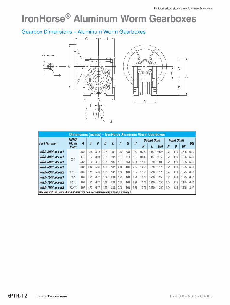
IronHorse® Aluminum Worm GearboxesGearbox Dimensions – Aluminum Worm Gearboxes
Dimensions (inches) – IronHorse Aluminum Worm Gearboxes
Part NumberNEMA Motor Face
A B C D E F G HOutput Bore Input Shaft
ØQK L ØM N O ØP
WGA-30M-xxx-H1
56C
3.82 2.48 3.15 2.24 1.57 1.18 2.89 1.57 0.720 0.187 0.625 0.73 0.19 0.625 6.50
WGA-40M-xxx-H1 4.78 3.07 3.94 2.81 1.97 1.57 3.18 1.97 0.840 0.187 0.750 0.71 0.19 0.625 6.50
WGA-50M-xxx-H1 5.67 3.62 4.72 3.31 2.36 1.97 3.58 2.36 1.110 0.250 1.000 0.71 0.19 0.625 6.50
WGA-63M-xxx-H1 6.87 4.42 5.69 4.00 2.87 2.48 4.06 2.84 1.250 0.250 1.125 0.71 0.19 0.625 6.50
WGA-63M-xxx-H2 145TC 6.87 4.42 5.69 4.00 2.87 2.48 4.06 2.84 1.250 0.250 1.125 0.97 0.19 0.875 6.50
WGA-75M-xxx-H1 56C 8.07 4.72 6.77 4.69 3.39 2.95 4.68 3.39 1.375 0.250 1.250 0.71 0.19 0.625 6.50
WGA-75M-xxx-H2 145TC 8.07 4.72 6.77 4.69 3.39 2.95 4.68 3.39 1.375 0.250 1.250 1.24 0.25 1.125 6.50
WGA-75M-xxx-H3 182/4TC 8.07 4.72 6.77 4.69 3.39 2.95 4.68 3.39 1.375 0.250 1.250 1.24 0.25 1.125 8.97
See our website: www.AutomationDirect.com for complete engineering drawings.
1 - 8 0 0 - 6 3 3 - 0 4 0 5Power TransmissiontPTR-12
For latest prices, please check AutomationDirect.com.
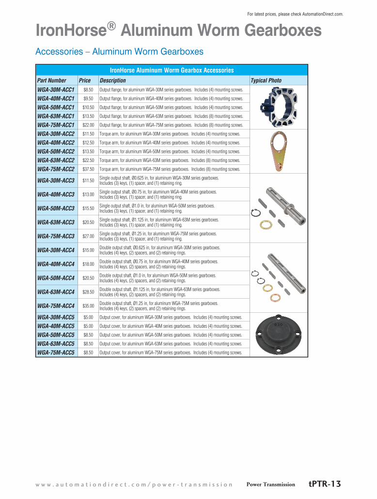
Accessories – Aluminum Worm Gearboxes
IronHorse® Aluminum Worm Gearboxes
IronHorse Aluminum Worm Gearbox AccessoriesPart Number Price Description Typical Photo
WGA-30M-ACC1 $8.50 Output flange, for aluminum WGA-30M series gearboxes. Includes (4) mounting screws.
WGA-40M-ACC1 $9.50 Output flange, for aluminum WGA-40M series gearboxes. Includes (4) mounting screws.
WGA-50M-ACC1 $10.50 Output flange, for aluminum WGA-50M series gearboxes. Includes (4) mounting screws.
WGA-63M-ACC1 $13.50 Output flange, for aluminum WGA-63M series gearboxes. Includes (8) mounting screws.
WGA-75M-ACC1 $22.00 Output flange, for aluminum WGA-75M series gearboxes. Includes (8) mounting screws.
WGA-30M-ACC2 $11.50 Torque arm, for aluminum WGA-30M series gearboxes. Includes (4) mounting screws.
WGA-40M-ACC2 $12.50 Torque arm, for aluminum WGA-40M series gearboxes. Includes (4) mounting screws.
WGA-50M-ACC2 $13.50 Torque arm, for aluminum WGA-50M series gearboxes. Includes (4) mounting screws.
WGA-63M-ACC2 $22.50 Torque arm, for aluminum WGA-63M series gearboxes. Includes (8) mounting screws.
WGA-75M-ACC2 $37.50 Torque arm, for aluminum WGA-75M series gearboxes. Includes (8) mounting screws.
WGA-30M-ACC3 $11.50 Single output shaft, Ø0.625 in, for aluminum WGA-30M series gearboxes. Includes (3) keys, (1) spacer, and (1) retaining ring.
WGA-40M-ACC3 $13.00 Single output shaft, Ø0.75 in, for aluminum WGA-40M series gearboxes. Includes (3) keys, (1) spacer, and (1) retaining ring.
WGA-50M-ACC3 $15.50 Single output shaft, Ø1.0 in, for aluminum WGA-50M series gearboxes. Includes (3) keys, (1) spacer, and (1) retaining ring.
WGA-63M-ACC3 $20.50 Single output shaft, Ø1.125 in, for aluminum WGA-63M series gearboxes. Includes (3) keys, (1) spacer, and (1) retaining ring.
WGA-75M-ACC3 $27.00 Single output shaft, Ø1.25 in, for aluminum WGA-75M series gearboxes. Includes (3) keys, (1) spacer, and (1) retaining ring.
WGA-30M-ACC4 $15.00 Double output shaft, Ø0.625 in, for aluminum WGA-30M series gearboxes. Includes (4) keys, (2) spacers, and (2) retaining rings.
WGA-40M-ACC4 $18.00 Double output shaft, Ø0.75 in, for aluminum WGA-40M series gearboxes. Includes (4) keys, (2) spacers, and (2) retaining rings.
WGA-50M-ACC4 $20.50 Double output shaft, Ø1.0 in, for aluminum WGA-50M series gearboxes. Includes (4) keys, (2) spacers, and (2) retaining rings.
WGA-63M-ACC4 $28.50 Double output shaft, Ø1.125 in, for aluminum WGA-63M series gearboxes. Includes (4) keys, (2) spacers, and (2) retaining rings.
WGA-75M-ACC4 $35.00 Double output shaft, Ø1.25 in, for aluminum WGA-75M series gearboxes. Includes (4) keys, (2) spacers, and (2) retaining rings.
WGA-30M-ACC5 $5.00 Output cover, for aluminum WGA-30M series gearboxes. Includes (4) mounting screws.
WGA-40M-ACC5 $5.00 Output cover, for aluminum WGA-40M series gearboxes. Includes (4) mounting screws.
WGA-50M-ACC5 $8.50 Output cover, for aluminum WGA-50M series gearboxes. Includes (4) mounting screws.
WGA-63M-ACC5 $8.50 Output cover, for aluminum WGA-63M series gearboxes. Includes (4) mounting screws.
WGA-75M-ACC5 $8.50 Output cover, for aluminum WGA-75M series gearboxes. Includes (4) mounting screws.
Power Transmissionw w w . a u t o m a t i o n d i r e c t . c o m / p o w e r - t r a n s m i s s i o n tPTR-13
For latest prices, please check AutomationDirect.com.
IronHorse® Worm GearboxesGearbox SelectionGearbox Selection Steps1) Determine the torque and speed required for the load.
2) Determine the overall speed ratio of motor speed to load speed.
3) Determine the gearbox ratio as well as any reduction outside the gearbox (pulleys, gears, etc.).
4) Determine the applicable service factor and overhung load K factor.
5) Determine the gearbox real output torque required, and select a gearbox with a higher Maximum Thermal output Torque rating (for WG cast-iron gearboxes; not applicable for WGA aluminum gearboxes).
6) Determine the gearbox design output torque required (torque with service factor applied), and select a gearbox with a higher Maximum Mechanical Output Torque rating. (Gearbox must also meet requirement #5.)
7) Determine the required sizes of pulleys, gears, etc., and determine the overhung load force. Select a gearbox with a higher Overhung Load rating. (Gearbox must also meet requirements #5 & #6.)
8) Confirm that the selected gearbox meets the applicable system requirements.
9) Select a compatible motor.
Gearbox Selection Example (Refer to the specifications tables for gearbox specifications, service factors, and K factors.)A conveyor will run 10 hours/day with moderate shock loading. The conveyor will be driven by a V-belt and needs to be driven at approximately 20 rpm. The motor to be used will have a nominal speed of 1800 rpm (1725 rpm actual speed). The conveyor will require 2700 in·lb of torque.
1) Required torque = 2700 in·lb; required speed = 20 rpm.
2) Determine the overall speed ratio of motor speed to load speed: Overall speed ratio = motor speed / load speed = 1725 / 20 = 86.25 [about 86:1]
3) Determine pulley ratios at available gearbox ratios: Gearbox ratio = (overall speed ratio) / (pulley ratio) Pulley ratio = (overall speed ratio) / (gearbox ratio) For 5:1 gearbox: pulley ratio = 86.25 / 5 = 17.25 [17.25” pulley ratio is prohibitively large] For 10:1 gearbox: pulley ratio = 86.25 / 10 = 8.63 For 15:1 gearbox: pulley ratio = 86.25 / 15 = 5.75 For 20:1 gearbox: pulley ratio = 86.25 / 20 = 4.31 For 30:1 gearbox: pulley ratio = 86.25 / 30 = 2.88 For 40:1 gearbox: pulley ratio = 86.25 / 40 = 2.16 For 60:1 gearbox: pulley ratio = 86.25 / 60 = 1.44 Pulley ratio = (conveyor pulley diameter) / (gearbox pulley diameter)
4) Determine service factor (SF) and overhung load factor (K) from applicable tables: SF = 1.25 due to moderate shock loading and 3-10 hours/day operation K = 1.5 due to V-belt
5) Use specifications table to select gearbox with Maximum Thermal* Torque rating > required real torque: Gearbox required real torque = (final torque) / (pulley ratio) For 10:1 gearbox: (2700 in·lb) / 8.63 = 312.86 in·lb; use WG-175-x or larger For 15:1 gearbox: (2700 in·lb) / 5.75 = 469.57 in·lb; use WG-175-x or larger For 20:1 gearbox: (2700 in·lb) / 4.31 = 626.45 in·lb; use WG-206-x or larger For 30:1 gearbox: (2700 in·lb) / 2.88 = 937.50 in·lb; use WG-325-x or WGA-63M* For 40:1 gearbox: (2700 in·lb) / 2.16 = 1250.0 in·lb; use WG-325-x For 60:1 gearbox: (2700 in·lb) / 1.44 = 1875.0 in·lb; use WG-325-x * Aluminum gearboxes do not have thermal ratings; use mechanical ratings.
6) Use specifications table to select gearbox with Maximum Mechanical Torque rating > required design torque: Gearbox required design torque = (real gearbox torque)(service factor) For 10:1 gearbox: (312.86 in·lb)(1.25) = 391.08 in·lb; use WG-175-x or larger For 15:1 gearbox: (469.57 in·lb)(1.25) = 586.96 in·lb; use WG-206-x or larger For 20:1 gearbox: (646.45 in·lb)(1.25) = 808.06 in·lb; use WG-206-x or larger For 30:1 gearbox: (937.50 in·lb)(1.25) = 1178.88 in·lb; use WG-325-x or WGA-63M or larger For 40:1 gearbox: (1250.0 in·lb)(1.25) = 1562.50 in·lb; use WG-325-x For 60:1 gearbox: (1875.0 in·lb)(1.25) = 2343.75 in·lb; use WG-325-x
(continued on next page)
1 - 8 0 0 - 6 3 3 - 0 4 0 5Power TransmissiontPTR-14
For latest prices, please check AutomationDirect.com.

IronHorse® Worm GearboxesGearbox Selection Example (continued)(Refer to the specifications tables for gearbox specifications, service factors, and K factors.) [Load requirements: Conveyor to run 10 hours/day; moderate shock loading; driven by V-belt @ approx 20 rpm;
requires 2700 in·lb of torque. Motor speed 1725 rpm (1800 rpm nominal).
7) Use the gearbox overhung load ratings from the specifications table to determine the minimum allowable pulley diameters. Select gearbox with Overhung Load rating > overhung load force: Gearbox required OHL rating = (gearbox real torque)(K)(SF)/(gearbox pulley diameter / 2) Minimum gearbox pulley diameter = (T)(K)(SF)(2)/(OHL rating) Conveyor pulley diameter = (gearbox pulley diameter)(pulley ratio) For 10:1, WG-175-010-x gearbox: Minimum gearbox pulley diameter = (312.86 in·lb)(1.5)(1.25)(2)/(650 lb) = 1.8” [use 2”] Conveyor pulley diameter = (2”)(8.63) = 17.26” [17.26” pulley size is prohibitively large] Determine pulley sizes and OHL for next larger gearbox ratio. For 15:1, WG-206-015-x gearbox: Minimum gearbox pulley diameter = (469.57 in·lb)(1.5)(1.25)(2)/(700 lb) = 2.5” [use 2.5”] Conveyor pulley diameter = (2.5”)(5.75) = 14.38” [use 14.4”] Select WG-206-015-x gearbox, 2.5” gearbox pulley, and 14.4” conveyor pulley. For 20:1, WG-206-020-x gearbox: N/A – larger ratio of same frame size GB is same price, yet provides lower efficiency and power characteristics For 30:1, WGA-63M-030-H1 gearbox: Minimum gearbox pulley diameter = (937.50 in·lb)(1.5)(1.25)(2)/(736 lb) = 4.78” [use 5”] Conveyor pulley diameter = (5”)(2.88) = 14.40” [use 14.4”] N/A – WGA-63M & WG-325 gearboxes costs more than WG-206 For 40:1, N/A – WG-325-xxx gearboxes cost more than WG-206 at any ratio For 60:1, N/A – WG-325-xxx gearboxes cost more than WG-206 at any ratio
8) Check results against original speed and torque requirements: a) Conveyor speed = (motor speed) / (gearbox ratio)(pulley ratio) = (1725 rpm) / (15)(14.4”/2.5”) = 20 rpm b) Maximum real torque available at conveyor = (gearbox thermal torque)(pulley ratio) = (673 in·lb)(14.4”/2.5”) = 3876 in·lb c) Maximum design torque available at conveyor = (gearbox mechanical torque)(pulley ratio) / (service factor) = (1002 in·lb)(14.4”/2.5”) / 1.25 = 4617 in·lb The speed is correct as required, and both maximum torque values are greater than the 2700 in·lb required by the load.
9) Select a motor and check torque transmitted to the load: From the gearbox spec tables, WG-206-015-x efficiency = 85%. maximum thermal input power = 1.40 hp maximum mechanical input power @ 1.0 SF = 2.09 hp maximum mechanical input power @ 1.25 SF = (rated max mechanical input power) / (SF) = 2.09 hp / 1.25 = 1.67 hp maximum allowable motor power = 1.40 hp; select nominal 1hp motor Select 1hp motor, and check for adequate torque at the load: Torque = Power / Speed [conversion factor: (1hp) = (63,025 in·lb·rpm)] Torque load = (63,025 in·lb·rpm / hp)(gearbox input hp)(gearbox efficiency) / (motor rpm / (gearbox ratio)(pulley ratio)) = (63,025)(1)(0.85) / (1725 / (15/1)(14.4/2.5)) = 2683 in·lb [insufficient torque at load] This torque value is less than the 2700 in·lb required by the load. So, select and check the next larger nominal motor size, which is 1-1/2 hp. Since the 206 frame size 15 ratio gearboxes do not meet the 1-1/2 hp thermal rating, choose the WG-237-015-x gearbox. Select 1-1/2 hp motor and WG-237-015-x gearbox, and check for adequate torque: WG-237-015-x gearbox efficiency = 84% maximum thermal input power = 1.55 hp maximum mechanical input power @ 1.25 SF = 2.64 hp / 1.25 = 2.11 hp maximum allowable motor power = 1.55 hp; select nominal 1-1/2 hp motor gearbox ratio is still 15:1, and OHL rating is increased to 900 lb, so the previous pulley calculations [step 7] remain sufficient [smaller pulleys can be calculated and selected for this gearbox, if desired] Tload = (63,025 in·lb·rpm/hp) (1.5hp) (84%) / (1725 rpm / (15/1)(14.4/2.5)) = 3977 in·lb > 2700 in·lb; sufficient torque at load
Final gearbox and motor selection: 1-1/2 hp motor WG-237-015-x gearbox
Power Transmissionw w w . a u t o m a t i o n d i r e c t . c o m / p o w e r - t r a n s m i s s i o n tPTR-15
For latest prices, please check AutomationDirect.com.
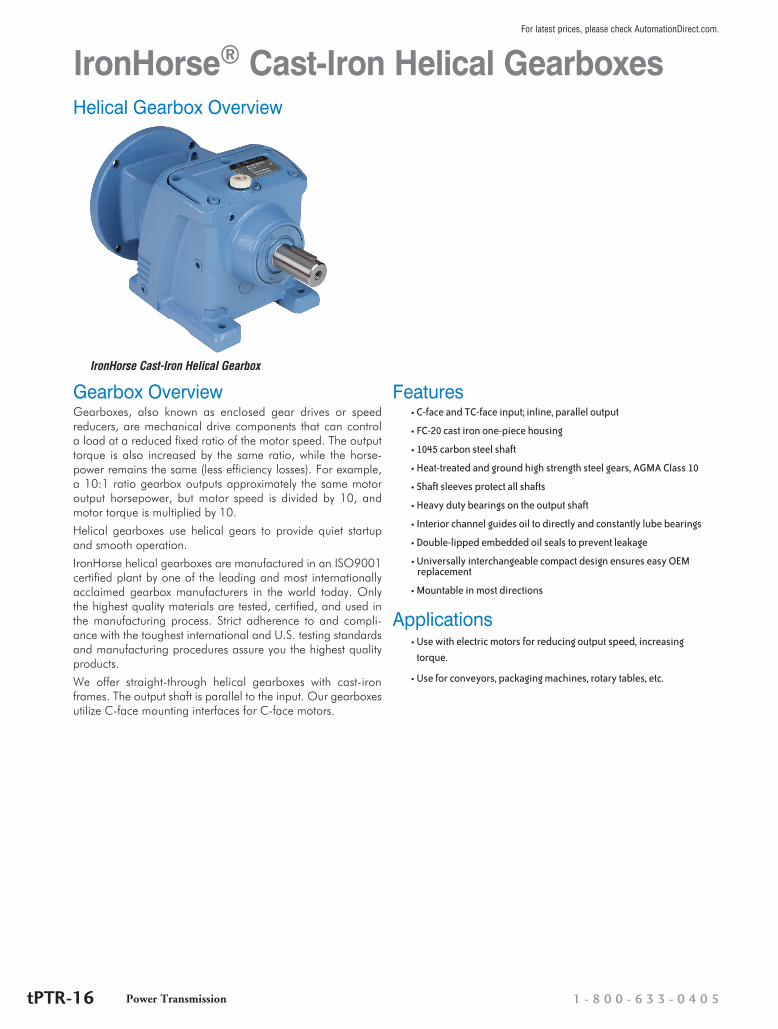
IronHorse® Cast-Iron Helical Gearboxes
Gearbox OverviewGearboxes, also known as enclosed gear drives or speed reducers, are mechanical drive components that can control a load at a reduced fixed ratio of the motor speed. The output torque is also increased by the same ratio, while the horse-power remains the same (less efficiency losses). For example, a 10:1 ratio gearbox outputs approximately the same motor output horsepower, but motor speed is divided by 10, and motor torque is multiplied by 10.
Helical gearboxes use helical gears to provide quiet startup and smooth operation.
IronHorse helical gearboxes are manufactured in an ISO9001 certified plant by one of the leading and most internationally acclaimed gearbox manufacturers in the world today. Only the highest quality materials are tested, certified, and used in the manufacturing process. Strict adherence to and compli-ance with the toughest international and U.S. testing standards and manufacturing procedures assure you the highest quality products.
We offer straight-through helical gearboxes with cast-iron frames. The output shaft is parallel to the input. Our gearboxes utilize C-face mounting interfaces for C-face motors.
IronHorse Cast-Iron Helical Gearbox
Helical Gearbox Overview
Features• C-face and TC-face input; inline, parallel output
• FC-20 cast iron one-piece housing
• 1045 carbon steel shaft
• Heat-treated and ground high strength steel gears, AGMA Class 10
• Shaft sleeves protect all shafts
• Heavy duty bearings on the output shaft
• Interior channel guides oil to directly and constantly lube bearings
• Double-lipped embedded oil seals to prevent leakage
• Universally interchangeable compact design ensures easy OEM replacement
• Mountable in most directions
Applications• Use with electric motors for reducing output speed, increasing
torque.
• Use for conveyors, packaging machines, rotary tables, etc.
1 - 8 0 0 - 6 3 3 - 0 4 0 5Power TransmissiontPTR-16
For latest prices, please check AutomationDirect.com.
IronHorse® Cast-Iron Helical Gearboxes
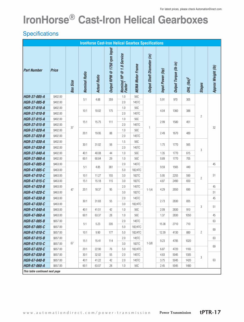
IronHorse Cast-Iron Helical Gearbox Specifications
Part Number PriceBo
x Si
ze
Nom
inal
Rat
io
Actu
al R
atio
Outp
ut R
PM @
175
0 rp
m In
put
Nom
inal
HP
@ 1
.0 S
ervi
ce
Fact
or 1
NEM
A M
otor
Fra
me
Outp
ut S
haft
Diam
eter
(in)
Inpu
t Pow
er (h
p)
Outp
ut T
orqu
e (lb
·in)
OHL
(lbs)
2
Stag
es
Appr
ox W
eigh
t (lb
)
HGR-37-005-A $402.00
37
5:1 4.88 3591.0 56C
1
5.91 970 305
2
32
HGR-37-005-B $402.00 2.0 145TC
HGR-37-010-A $402.0010:1 10.02 175
1.0 56C4.04 1360 388
HGR-37-010-B $402.00 2.0 145TC
HGR-37-015-A $402.0015:1 15.75 111
1.0 56C2.99 1580 451
HGR-37-015-B $402.00 2.0 145TC
HGR-37-020-A $402.0020:1 19.95 88
1.0 56C2.49 1670 489
HGR-37-020-B $402.00 2.0 145TC
HGR-37-030-A $402.0030:1 31.02 56
1.5 56C1.75 1770 565
3HGR-37-030-B $402.00 2.0 145TC
HGR-37-040-A $402.00 40:1 40.08 44 1.0 56C 1.35 1770 615
HGR-37-060-A $402.00 60:1 60.84 29 1.0 56C 0.89 1770 705
HGR-47-005-B $463.00
47
5:1 4.85 3612.0 145TC
1-1/4
9.59 1565 440
2
45
HGR-47-005-C $463.00 5.0 182/4TC
51HGR-47-010-C $463.00 10:1 11.27 155 3.0 182TC 5.95 2255 590
HGR-47-015-C $463.00 15:1 15.18 115 3.0 182TC 4.87 2490 650
HGR-47-020-B $463.0020:1 18.37 95
2.0 145TC4.29 2650 690
45
HGR-47-020-C $463.00 3.0 182TC 51
HGR-47-030-B $463.0030:1 31.83 55
2.0 145TC2.73 2830 835
3
45
HGR-47-030-C $463.00 3.0 182/4TC51
HGR-47-040-A $463.00 40:1 41.51 42 1.0 56C 2.09 2830 910
HGR-47-060-A $463.00 60:1 63.37 28 1.0 56C 1.37 2830 1050 45
HGR-67-005-B $657.00
67
5:1 5.23 3352.0 145TC
1-3/8
15.38 2710 710
2
63
HGR-67-005-C $657.00 5.0 182/4TC69
HGR-67-010-C $657.00 10:1 9.90 177 5.0 182/4TC 12.39 4130 880
HGR-67-015-B $657.0015:1 15.41 114
2.0 145TC9.23 4785 1020
63
HGR-67-015-C $657.00 3.0 182TC69
HGR-67-020-C $657.00 20:1 22.90 76 5.0 182/4TC 6.87 4720 1165
3HGR-67-030-B $657.00 30:1 32.02 55 2.0 145TC 4.83 5045 1305
63HGR-67-040-B $657.00 40:1 41.22 42 2.0 145TC 3.75 5045 1420
HGR-67-060-A $657.00 60:1 63.07 28 1.0 56C 2.45 5045 1480
This table continued next page
Specifications
Power Transmissionw w w . a u t o m a t i o n d i r e c t . c o m / p o w e r - t r a n s m i s s i o n tPTR-17
For latest prices, please check AutomationDirect.com.
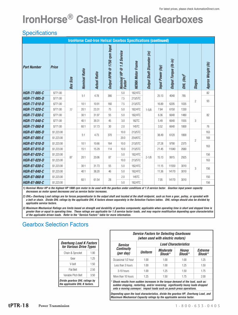
IronHorse Cast-Iron Helical Gearbox Specifications (continued)
Part Number PriceBo
x Si
ze
Nom
inal
Rat
io
Actu
al R
atio
Outp
ut R
PM @
175
0 rp
m In
put
Nom
inal
HP
@ 1
.0 S
ervi
ce
Fact
or 1
NEM
A M
otor
Fra
me
Outp
ut S
haft
Diam
eter
(in)
Inpu
t Pow
er (h
p)
Outp
ut T
orqu
e (lb
·in)
OHL
(lbs)
2
Stag
es
Appr
ox W
eigh
t (lb
)
HGR-77-005-C $771.00
77
5:1 4.78 3665.0 182/4TC
1-5/8
25.13 4040 785
2
82
HGR-77-005-D $771.00 7.5 213/5TC93
HGR-77-010-D $771.00 10:1 10.91 160 7.5 213/5TC 16.89 6205 1035
HGR-77-020-C $771.00 20:1 23.31 75 5.0 182/4TC 7.84 6150 1330
82HGR-77-030-C $771.00 30:1 31.97 55 5.0 182/4TC 6.36 6640 1480
3HGR-77-040-C $771.00 40:1 39.31 45 3.0 182TC 5.49 6640 1555
HGR-77-060-B $771.00 60:1 57.73 30 2.0 145TC 3.52 6640 1800 76
HGR-87-005-D $1,223.00
87
5:1 4.73 37010.0 213/5TC
2-1/8
38.49 6120 1800
2
163
HGR-87-005-E $1,223.00 20.0 254/6TC 169
HGR-87-010-D $1,223.00 10:1 10.66 164 10.0 213/5TC 27.28 9790 2375163
HGR-87-015-D $1,223.00 15:1 15.29 114 10.0 213/5TC 21.45 11040 2680
HGR-87-020-C $1,223.0020:1 20.06 87
5.0 182/4TC15.13 9915 2925
3
156
HGR-87-020-D $1,223.00 10.0 213/5TC 163
HGR-87-030-C $1,223.00 30:1 31.73 55 5.0 182/4TC 11.15 11550 3010156
HGR-87-040-C $1,223.00 40:1 38.20 46 5.0 182/4TC 11.36 14170 3010
HGR-87-060-B $1,223.0060:1 61.54 28
2.0 145TC7.05 14170 3010
150
HGR-87-060-C $1,223.00 5.0 182/4TC 156
1) Nominal Motor HP is the highest HP 1800 rpm motor to be used with the gearbox under conditions of 1.0 service factor. Gearbox input power capacity decreases as motor speed decreases and as service factor increases.
2) OHL= Overhung Load ratings are for forces perpendicular to the output shaft and located at the shaft midpoint, such as from a gear, pulley, or sprocket with a belt or chain. Divide OHL ratings by the applicable OHL K factors shown separately in the Selection Factors tables. OHL ratings should also be divided by applicable service factors.
3) Maximum Mechanical Ratings are limits based on strength and durability of gearbox components; applicable when operating time is short and stopped time is greater than or equal to operating time. These ratings are applicable for 1.0 service factor loads, and may require modification depending upon characteristics of the applicable driven loads. Refer to the “Service Factors” table for more information.
IronHorse® Cast-Iron Helical GearboxesSpecifications
Gearbox Selection FactorsService Factors for Selecting Gearboxes
(when used with electric motors)
Service Continuity (per day)
Load Characteristics
Uniform Moderate Shock*
Heavy Shock*
Extreme Shock*
Occasional 1/2 hour 1.00 1.00 1.00 1.25
Less than 3 hours 1.00 1.00 1.25 1.50
3-10 hours 1.00 1.25 1.50 1.75
More than 10 hours 1.25 1.50 1.75 2.00
* Shock results from sudden increases in the torque demand of the load, such as: sudden stopping, restarting, and/or reversing; significantly heavy loads dropped onto a moving conveyor; impact loads such as punch press operations.
Depending upon the load characteristics, divide the gearbox HP, Overhung Load, and Maximum Mechanical Capacity ratings by the applicable service factor.
Overhung Load K Factors for Various Drive Types
Chain & Sprocket 1.00
Gear 1.25
V-belt 1.50
Flat Belt 2.50
Variable Pitch Belt 3.50
Divide gearbox OHL ratings by the applicable OHL K factors.
1 - 8 0 0 - 6 3 3 - 0 4 0 5Power TransmissiontPTR-18
For latest prices, please check AutomationDirect.com.

IronHorse® Cast-Iron Helical GearboxesDimensions
Units: inches [mm]
Dimensions – inches [mm] – IronHorse Cast-Iron Helical Gearboxes
Part Number Frame A B C D E F G H J K
HGR-37-xxx-A
56C
6.40 [162.5]
5.71 [145.0]
3.54 [90.0]
10.55 [268.0]
6.30 [160.0]
3.05 [77.5]
1.00 [25.4]
0.63 [15.9]
0.25 [6.4]
0.19 [4.8]
HGR-47-xxx-A 8.25 [209.5]
6.69 [170.0]
4.53 [115.0]
11.63 [295.4]
7.68 [195.0]
3.98 [101.0]
1.25 [31.8]
HGR-67-xxx-A 8.89 [226.0]
8.27 [210.0]
5.12 [130.0]
13.13 [333.5]
9.25 [235.0]
4.45 [113.0]
1.38 [34.9]
0.31 [7.9]
HGR-37-xxx-B
145TC
6.40 [162.5]
5.71 [145.0]
3.54 [90.0]
10.94 [278.0]
6.30 [160.0]
3.05 [77.5]
1.00 [25.4]
0.88 [22.2]
0.25 [6.4]
HGR-47-xxx-B 8.25 [209.5]
6.69 [170.0]
4.53 [115.0]
12.03 [305.5]
7.68 [195.0]
3.98 [101.0]
1.25 [31.8]
HGR-67-xxx-B 8.89 [226.0]
8.27 [210.0]
5.12 [130.0]
13.52 [343.5]
9.25 [235.0]
4.45 [113.0]
1.38 [34.9]
0.31 [7.9]
HGR-77-xxx-B 10.04 [255.0]
9.06 [230.0]
5.51 [140.0]
14.23 [361.5]
9.65 [245.0]
6.38 [162.0]
1.63 [41.4]
0.38 [9.7]
HGR-87-xxx-B 12.99 [330.0]
11.42 [290.0]
7.09 [180.0]
17.20 [437.0]
12.20 [310.0]
8.05 [204.5]
2.13 [54.1]
0.50 [12.7]
HGR-47-xxx-C
182/4TC*
8.25 [209.5]
6.69 [170.0]
4.53 [115.0]
12.76 [324.0]
7.68 [195.0]
3.98 [101.0]
1.25 [31.8]
1.13 [28.7]
0.25 [6.4]
0.25 [6.4]
HGR-67-xxx-C 8.89 [226.0]
8.27 [210.0]
5.12 [130.0]
14.25 [362.0]
9.25 [235.0]
4.45 [113.0]
1.38 [34.9]
0.31 [7.9]
HGR-77-xxx-C 10.04 [255.0]
9.06 [230.0]
5.51 [140.0]
14.96 [380.0]
9.65 [245.0]
6.38 [162.0]
1.63 [41.4]
0.38 [9.7]
HGR-87-xxx-C 12.99 [330.0]
11.42 [290.0]
7.09 [180.0]
17.32 [440.0]
12.20 [310.0]
8.05 [204.5]
2.13 [54.1]
0.50 [12.7]
HGR-77-xxx-D213/5TC
10.04 [255.0]
9.06 [230.0]
5.51 [140.0]
17.22 [437.5]
9.65 [245.0]
6.38 [162.0]
1.63 [41.4] 1.38
[35.0]
0.38 [9.7] 0.31
[7.9]HGR-87-xxx-D 12.99
[330.0]11.42
[290.0]7.09
[180.0]19.59
[497.5]12.20
[310.0]8.05
[204.5]2.13
[54.1]0.50
[12.7]
HGR-87-xxx-E 254/6TC12.99
[330.0]11.42
[290.0]7.09
[180.0]20.57
[522.5]12.20
[310.0]8.05
[204.5]2.13
[54.1]1.63
[41.4]0.50
[12.7]0.38 [9.7]
*Note: 184TC motor frame sizes where applicable. See gearbox specifications for more information.
See our website: www.AutomationDirect.com for complete engineering drawings.
Power Transmissionw w w . a u t o m a t i o n d i r e c t . c o m / p o w e r - t r a n s m i s s i o n tPTR-19
For latest prices, please check AutomationDirect.com.

IronHorse® Shaft Mount Gearboxes
Gearbox OverviewGearboxes, also known as enclosed gear drives or speed reducers, are mechanical drive components that drive a load at a reduced fixed ratio of the motor speed. The output torque is also increased by the same ratio, while the horsepower remains the same (less efficiency losses.) For example, a 10:1 ratio gearbox outputs approximately the same motor output horsepower, motor speed divided by 10, and motor torque multiplied by 10.
IronHorse® Shaft Mount Gearboxes feature shafts and gears manufactured from the highest grade steel, case hardened and precision ground to AGMA standards for long lasting durability. Housings are 100% cast iron to provide industrial grade protection for the life of the unit. Shafts are sealed with reinforced double lip to protect against contamination and prevent oil from escaping. Premium ball and tapered roller bearings provide smooth operation and lower noise (bushings are avail-able, but not included). Extended gear centers ensure tooth contact and provide consistent operation. Bore type is tapered.
Features• 9:1, 15:1 and 25:1 ratios
• Frame sizes 2 to 5
• Industrial grade cast-iron housings protect gearing for life
• Extended gear centers and tooth contact
• Metal reinforced double lip, spring loaded oil seals
• Dimensional drop-in for all major makes
• Torque arm included
Applications• Use with electric motors for reducing output speed, increasing
torque, changing drive direction, and/or running two loads from one motor.
• Use for belt conveyors, screw conveyors, or material handling
IronHorse Shaft Mount Gearbox IronHorse Shaft Mount Gearbox Accessories
Output Shaft Overhung Load Ratings
Frame Size
Shaft Size
Overhung Load (lb) at Various RPMs10 20 30 50 80 100 120 140 160 180 200
21-7/16” 2000 1510 1270 1010 840 820 720 720 710 710 700
1-15/16” 1750 1320 1110 890 730 710 630 630 620 620 610
31-15/16” 5400 4250 3680 3050 2620 2440 2310 2210 2110 2040 1980
2-3/16” 5240 4120 3570 2960 2540 2370 2240 2140 2050 1980 1920
42-3/16” 6520 5180 4510 3800 3230 3000 2830 2710 2600 2510 2430
2-7/16” 6360 5060 4410 3710 3160 2930 2770 2640 2530 2450 2370
52-7/16” 7460 5860 5080 4280 3690 3450 3270 3110 2980 2880 2790
2-15/16” 7060 5540 4800 4040 3490 3260 3090 2940 2820 2720 2640
IronHorse® Shaft Mount Gearboxes
Part Number Price Ratio Actual
RatioMax RPM
Frame Size
Output Bore (max)
Weight (lb)
SMR2-09 $588.00 9:1 9.36 1872
2 1-15/16” 68SMR2-15 $588.00 15:1 14.04 1895
SMR2-25 $588.00 25:1 23.37 1986
SMR3-09 $877.00 9:1 9.21 1842
3 2-3/16” 106SMR3-15 $877.00 15:1 14.87 1859
SMR3-25 $877.00 25:1 24.75 2104
SMR4-09 $1,188.00 9:1 9.21 1842
4 2-7/16” 156SMR4-15 $1,188.00 15:1 15.13 1891
SMR4-25 $1,188.00 25:1 24.38 2072
SMR5-09 $1,798.00 9:1 9.10 1820
5 2-15/16” 204SMR5-15 $1,798.00 15:1 15.40 1848
SMR5-25 $1,798.00 25:1 25.56 2045
1 - 8 0 0 - 6 3 3 - 0 4 0 5Power TransmissiontPTR-20
For latest prices, please check AutomationDirect.com.
IronHorse® Shaft Mount Gearboxes
Mechanical Ratings
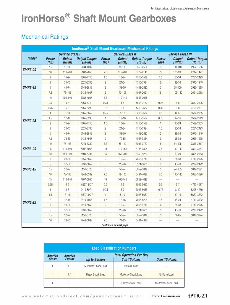
IronHorse® Shaft Mount Gearboxes Mechanical Ratings
ModelService Class I Service Class II Service Class III
Power(hp)
Output (RPM)
Output Torque (lb·in)
Power(hp)
Output (RPM)
Output Torque (lb·in)
Power(hp)
Output (RPM)
Output Torque (lb·in)
SMR2-097.5 78-105 5434-4037 5 78-110 3658-2594 3 58-110 2952-1556
10 110-200 5188-2853 7.5 115-200 3722-2140 5 105-200 2717-1427
SMR2-15
2 16-24 7065-4710 1.5 18-24 4710-3532 1.5 26-34 3261-2493
3 26-45 6521-3768 2 24-34 4710-3324 2 38-58 2975-1949
5 46-74 6143-3819 3 38-70 4462-2422 3 58-100 2923-1695
7.5 78-105 5434-4037 5 70-105 4037-2691 5 105-140 2691-2018
10 105-140 5382-4037 7.5 110-140 3853-3028 — — —
SMR2-25
0.5 4-6 7065-4710 0.33 4-5 4663-3730 0.25 4-5 3532-2826
0.75 6-8 7065-5298 0.5 6-8 4710-3532 0.33 6-8 3108-2331
1 8-10 7065-5652 0.75 8-12 5298-3532 0.5 8-12 3532-2355
1.5 12-16 7065-5298 1 12-16 4710-3532 0.75 12-16 3532-2649
2 16-24 7065-4710 1.5 18-24 4710-3532 1 16-24 3532-2355
3 26-45 6521-3768 2 24-34 4710-3324 1.5 26-34 3261-2493
5 46-74 6143-3819 3 38-70 4462-2422 2 38-58 2975-1949
7.5 78-85 5434-4987 5 70-85 4037-3324 3 58-85 2923-1995
SMR3-0910 78-105 7246-5382 7.5 85-110 5035-3722 5 74-105 3856-2817
15 110-140 7707-6055 10 110-150 5188-3804 7.5 110-140 3891-3057
20 150-200 7609-5707 15 160-200 5350-4280 10 150-200 3804-2853
SMR3-15
3 28-30 6055-5652 2 16-24 7065-4710 2 24-38 4710-2975
5 32-50 8831-5652 3 26-46 6521-3686 3 40-70 4239-2422
7.5 52-74 8151-5728 5 50-74 5652-3819 5 74-105 3819-2691
10 78-105 7246-5382 7.5 78-105 5434-4037 7.5 110-140 3853-3028
15 110-140 7707-6055 10 100-140 5652-4037 — — —
SMR3-25
0.75 4-5 10597-8477 0.5 4-5 7065-5652 0.5 6-7 4710-4037
1 6-7 9419-8074 0.75 6-7 7065-6055 0.75 8-10 5298-4239
1.5 8-10 10597-8477 1 8-10 7065-5652 1 10-16 5652-3532
2 12-16 9419-7065 1.5 12-16 7065-5298 1.5 18-24 4710-3532
3 18-30 9419-5652 2 16-24 7065-4710 2 24-38 4710-2975
5 32-50 8831-5652 3 26-46 6521-3686 3 40-70 4239-2422
7.5 52-74 8151-5728 5 50-74 5652-3819 5 74-85 3819-3324
10 78-85 7246-6649 7.5 78-85 5434-4987 — — —
Continued on next page
Load Classification Numbers
Service Class
Service Factor
Total Operation Per DayUp to 3 Hours 3 to 10 Hours Over 10 Hours
I 1.0 Moderate Shock Load Uniform Load —
II 1.4 Heavy Shock Load Moderate Shock Load Uniform Load
III 2.0 — Heavy Shock Load Moderate Shock Load
Power Transmissionw w w . a u t o m a t i o n d i r e c t . c o m / p o w e r - t r a n s m i s s i o n tPTR-21
For latest prices, please check AutomationDirect.com.
IronHorse® Shaft Mount GearboxesMechanical Ratings
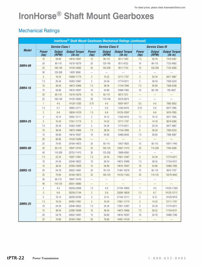
IronHorse® Shaft Mount Gearboxes Mechanical Ratings (continued)
ModelService Class I Service Class II Service Class III
Power(hp)
Output (RPM)
Output Torque (lb·in)
Power(hp)
Output (RPM)
Output Torque (lb·in)
Power(hp)
Output (RPM)
Output Torque (lb·in)
SMR4-09
15 58-80 14616-10597 15 90-115 9511-7443 7.5 58-78 7379-5487
20 80-110 14219-10276 20 120-140 9511-8152 10 80-115 7133-4962
25 100-140 14129-10092 25 150-200 9511-7133 15 120-200 7133-4280
30 120-200 14267-8560 — — — — — —
SMR4-15
5 18-24 15699-11774 3 14-22 12111-7707 3 20-34 8477-4987
7.5 26-34 16303-12467 5 24-34 11774-8311 5 38-54 7436-5233
10 38-54 14873-10466 7.5 38-54 11154-7849 7.5 58-80 7308-5298
15 58-80 14616-10597 10 54-80 10466-7065 10 80-140 765-4037
20 80-110 14219-10276 15 85-115 9973-7372 — — —
25 100-140 14129-10092 20 110-140 10276-8074 — — —
SMR4-25
1 4-5 14129-11303 0.75 4-5 10597-8477 0.5 4-5 7065-5652
1.5 5-7 16955-12111 1 5-6 11303-9419 0.75 5-6 8477-7065
2 6-8 18839-14129 1.5 6-8 14129-10597 1 6-8 9419-7065
3 10-14 16955-12111 2 10-12 11303-9419 1.5 10-12 8477-7065
5 16-24 17551-11774 3 14-22 12111-7707 2 14-18 8074-6280
7.5 26-34 16303-12467 5 24-34 11774-8311 3 20-34 8477-4987
10 38-54 14873-10466 7.5 38-54 11154-7849 5 38-54 7436-5233
15 58-80 14616-10597 10 54-85 10466-6649 7.5 58-85 7308-4987
20 80-85 14129-13298 — — — — — —
SMR5-0925 70-95 20184-14873 20 85-115 13427-9925 15 85-115 10071-7443
30 85-115 19947-14743 25 105-125 13587-11413 20 115-200 7443-4280
40 110-200 20752-11413 30 125-200 13696-8560 — — —
SMR5-15
7.5 22-24 19267-17661 7.5 24-34 17661-12467 5 24-34 11774-8311
10 24-34 23548-16622 10 38-54 14873-10466 7.5 38-52 11154-8151
15 38-54 22309-15699 15 58-80 14616-10597 10 54-80 10466-7065
20 54-78 20932-14491 20 78-110 11491-10276 15 85-110 9973-7707
25 70-95 20184-14873 25 100-125 14129-11303 20 110-125 10276-9043
30 85-115 19947-14743 — — — — — —
40 110-125 20551-18085 — — — — — —
SMR5-25
2 4-5 28258-22606 1.5 4-5 21194-16955 1 4-5 14129-11303
3 6-8 28258-21194 2 5-6 22606-18839 1.5 6-7 14129-12111
5 10-14 28258-20184 3 8-14 21194-12111 2 8-12 14129-9419
7.5 16-24 26492-17661 5 16-24 17661-11774 3 14-22 12111-7707
10 24-34 23548-16622 7.5 24-34 17661-12467 5 24-34 11774-8311
15 38-54 22309-15699 10 38-54 14873-10466 7.5 38-52 11154-8151
20 54-78 20932-14491 15 58-80 14616-10597 10 54-78 10466-7246
25 70-80 20184-17661 20 78-80 14491-14129 — — —
1 - 8 0 0 - 6 3 3 - 0 4 0 5Power TransmissiontPTR-22
For latest prices, please check AutomationDirect.com.
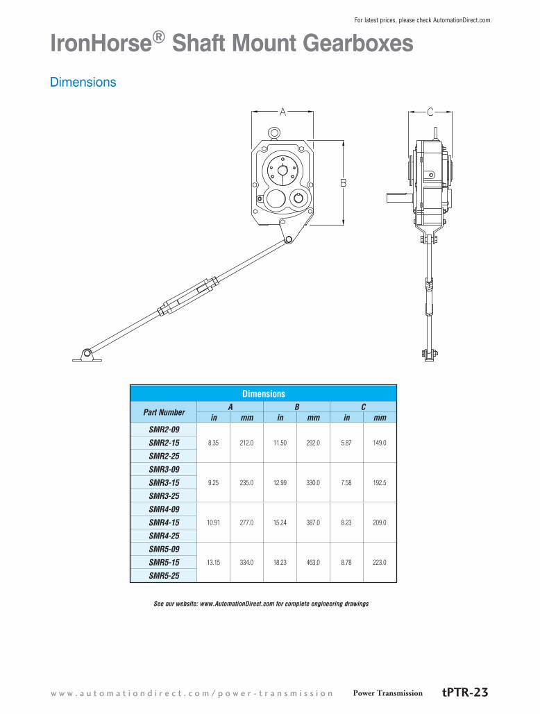
IronHorse® Shaft Mount GearboxesDimensions
See our website: www.AutomationDirect.com for complete engineering drawings
Dimensions
Part NumberA B C
in mm in mm in mmSMR2-09
8.35 212.0 11.50 292.0 5.87 149.0SMR2-15
SMR2-25
SMR3-099.25 235.0 12.99 330.0 7.58 192.5SMR3-15
SMR3-25
SMR4-0910.91 277.0 15.24 387.0 8.23 209.0SMR4-15
SMR4-25
SMR5-0913.15 334.0 18.23 463.0 8.78 223.0SMR5-15
SMR5-25
Power Transmissionw w w . a u t o m a t i o n d i r e c t . c o m / p o w e r - t r a n s m i s s i o n tPTR-23
For latest prices, please check AutomationDirect.com.
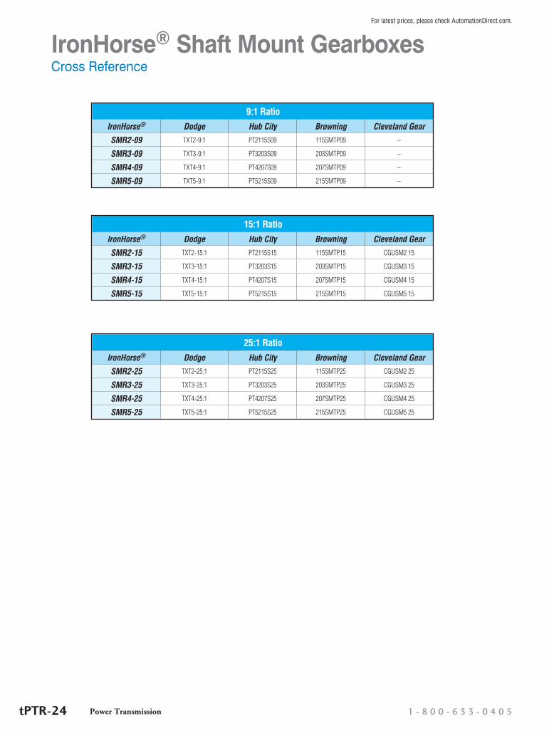
IronHorse® Shaft Mount GearboxesCross Reference
9:1 RatioIronHorse® Dodge Hub City Browning Cleveland Gear
SMR2-09 TXT2-9:1 PT2115S09 115SMTP09 –
SMR3-09 TXT3-9:1 PT3203S09 203SMTP09 –
SMR4-09 TXT4-9:1 PT4207S09 207SMTP09 –
SMR5-09 TXT5-9:1 PT5215S09 215SMTP09 –
15:1 RatioIronHorse® Dodge Hub City Browning Cleveland Gear
SMR2-15 TXT2-15:1 PT2115S15 115SMTP15 CGUSM2 15
SMR3-15 TXT3-15:1 PT3203S15 203SMTP15 CGUSM3 15
SMR4-15 TXT4-15:1 PT4207S15 207SMTP15 CGUSM4 15
SMR5-15 TXT5-15:1 PT5215S15 215SMTP15 CGUSM5 15
25:1 RatioIronHorse® Dodge Hub City Browning Cleveland Gear
SMR2-25 TXT2-25:1 PT2115S25 115SMTP25 CGUSM2 25
SMR3-25 TXT3-25:1 PT3203S25 203SMTP25 CGUSM3 25
SMR4-25 TXT4-25:1 PT4207S25 207SMTP25 CGUSM4 25
SMR5-25 TXT5-25:1 PT5215S25 215SMTP25 CGUSM5 25
1 - 8 0 0 - 6 3 3 - 0 4 0 5Power TransmissiontPTR-24
For latest prices, please check AutomationDirect.com.
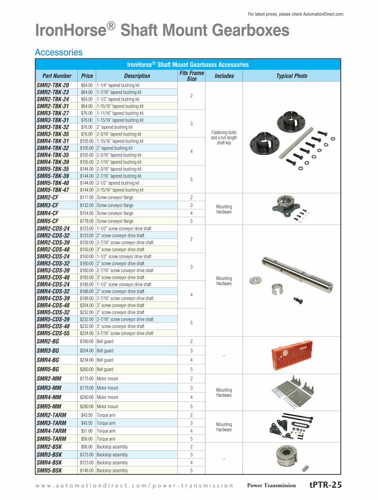
IronHorse® Shaft Mount GearboxesAccessories
IronHorse® Shaft Mount Gearboxes Accessories
Part Number Price Description Fits Frame Size Includes Typical Photo
SMR2-TBK-20 $64.00 1-1/4” tapered bushing kit
2
Fastening bolts and a full length
shaft key
SMR2-TBK-23 $64.00 1-7/16” tapered bushing kitSMR2-TBK-24 $64.00 1-1/2” tapered bushing kitSMR2-TBK-31 $64.00 1-15/16” tapered bushing kitSMR3-TBK-27 $76.00 1-11/16” tapered bushing kit
3SMR3-TBK-31 $76.00 1-15/16” tapered bushing kitSMR3-TBK-32 $76.00 2” tapered bushing kitSMR3-TBK-35 $76.00 2-3/16” tapered bushing kitSMR4-TBK-31 $105.00 1-15/16” tapered bushing kit
4SMR4-TBK-32 $105.00 2” tapered bushing kitSMR4-TBK-35 $105.00 2-3/16” tapered bushing kitSMR4-TBK-39 $105.00 2-7/16” tapered bushing kitSMR5-TBK-35 $144.00 2-3/16” tapered bushing kit
5SMR5-TBK-39 $144.00 2-7/16” tapered bushing kitSMR5-TBK-40 $144.00 2-1/2” tapered bushing kitSMR5-TBK-47 $144.00 2-15/16” tapered bushing kit
SMR2-CF $117.00 Screw conveyor flange 2
Mounting Hardware
SMR3-CF $132.00 Screw conveyor flange 3
SMR4-CF $154.00 Screw conveyor flange 4
SMR5-CF $178.00 Screw conveyor flange 5
SMR2-CDS-24 $123.00 1-1/2” screw conveyor drive shaft
2
Mounting Hardware
SMR2-CDS-32 $123.00 2” screw conveyor drive shaftSMR2-CDS-39 $156.00 2-7/16” screw conveyor drive shaftSMR2-CDS-48 $156.00 3” screw conveyor drive shaftSMR3-CDS-24 $160.00 1-1/2” screw conveyor drive shaft
3SMR3-CDS-32 $160.00 2” screw conveyor drive shaftSMR3-CDS-39 $160.00 2-7/16” screw conveyor drive shaftSMR3-CDS-48 $183.00 3” screw conveyor drive shaftSMR4-CDS-24 $186.00 1-1/2” screw conveyor drive shaft
4SMR4-CDS-32 $186.00 2” screw conveyor drive shaftSMR4-CDS-39 $186.00 2-7/16” screw conveyor drive shaftSMR4-CDS-48 $204.00 3” screw conveyor drive shaftSMR5-CDS-32 $232.00 2” screw conveyor drive shaft
5SMR5-CDS-39 $232.00 2-7/16” screw conveyor drive shaftSMR5-CDS-48 $232.00 3” screw conveyor drive shaftSMR5-CDS-55 $234.00 3-7/16” screw conveyor drive shaft
SMR2-BG $180.00 Belt guard 2
–SMR3-BG $204.00 Belt guard 3
SMR4-BG $234.00 Belt guard 4
SMR5-BG $260.00 Belt guard 5
SMR2-MM $175.00 Motor mount 2
Mounting Hardware
SMR3-MM $179.00 Motor mount 3
SMR4-MM $280.00 Motor mount 4
SMR5-MM $280.00 Motor mount 5
SMR2-TARM $43.50 Torque arm 2
Mounting Hardware
SMR3-TARM $43.50 Torque arm 3
SMR4-TARM $51.00 Torque arm 4
SMR5-TARM $56.00 Torque arm 5
SMR2-BSK $96.00 Backstop assembly 2
–SMR3-BSK $123.00 Backstop assembly 3
SMR4-BSK $123.00 Backstop assembly 4
SMR5-BSK $146.00 Backstop assembly 5
Power Transmissionw w w . a u t o m a t i o n d i r e c t . c o m / p o w e r - t r a n s m i s s i o n tPTR-25
For latest prices, please check AutomationDirect.com.

IronHorse® Shaft Mount GearboxesAccessories Dimensions
Bushings Dimensions
Part NumberA (Bore) B (Oal) C (Flange)
in mm in mm in mmSMR2-TBK-20 1.25 31.75 1.38 35.0 4.06 103.2
SMR2-TBK-23 1.4375 36.51 1.38 35.0 4.06 103.2
SMR2-TBK-24 1.5 38.10 1.38 35.0 4.06 103.2
SMR2-TBK-31 1.9375 49.21 1.38 35.0 4.06 103.2
SMR3-TBK-27 1.6875 42.86 1.63 41.5 4.37 111.1
SMR3-TBK-31 1.9375 49.21 1.63 41.5 4.37 111.1
SMR3-TBK-32 2.0 50.80 1.63 41.5 4.37 111.1
SMR3-TBK-35 2.1875 55.56 1.63 41.5 4.37 111.1
SMR4-TBK-31 1.9375 49.21 2.13 54.0 4.81 122.2
SMR4-TBK-32 2.0 50.80 2.13 54.0 4.81 122.2
SMR4-TBK-35 2.1875 55.56 2.13 54.0 4.81 122.2
SMR4-TBK-39 2.4375 61.91 2.13 54.0 4.81 122.2
SMR5-TBK-35 2.1875 55.56 2.07 52.5 5.63 142.9
SMR5-TBK-39 2.4375 61.91 2.07 52.5 5.63 142.9
SMR5-TBK-40 2.5 63.50 2.07 52.5 5.63 142.9
SMR5-TBK-47 2.9375 74.61 2.07 52.5 5.63 142.9
Bushings
See our website: www.AutomationDirect.com for complete engineering drawings
1 - 8 0 0 - 6 3 3 - 0 4 0 5Power TransmissiontPTR-26
For latest prices, please check AutomationDirect.com.
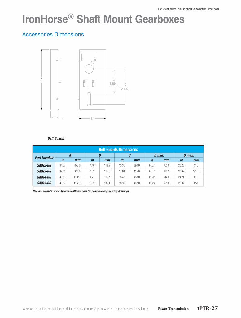
IronHorse® Shaft Mount GearboxesAccessories Dimensions
Belt Guards Dimensions
Part NumberA B C D min. D max.
in mm in mm in mm in mm in mmSMR2-BG 34.37 873.0 4.48 113.9 15.35 390.0 14.37 365.0 20.28 515
SMR3-BG 37.32 948.0 4.53 115.0 17.91 455.0 14.67 372.5 20.69 525.5
SMR4-BG 43.61 1107.8 4.71 119.7 18.43 468.0 16.22 412.0 24.21 615
SMR5-BG 45.67 1160.0 5.32 135.1 18.39 467.0 16.73 425.0 25.87 657
Belt Guards
See our website: www.AutomationDirect.com for complete engineering drawings
Power Transmissionw w w . a u t o m a t i o n d i r e c t . c o m / p o w e r - t r a n s m i s s i o n tPTR-27
For latest prices, please check AutomationDirect.com.
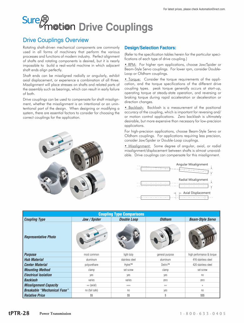
Drive Couplings Overview
Drive Couplings
Rotating shaft-driven mechanical components are commonly used in all forms of machinery that perform the various processes and functions of modern industry. Perfect alignment of shafts and rotating components is desired, but it is nearly impossible to build a real-world machine in which adjacent shaft ends align perfectly.
Shaft ends can be misaligned radially or angularly, exhibit axial displacement, or experience a combination of all three. Misalignment will place stresses on shafts and related parts of the assembly such as bearings, which can result in early failure of both.
Drive couplings can be used to compensate for shaft misalign-ment, whether the misalignment is an intentional or an unin-tentional part of the design. When designing or modifying a system, there are essential factors to consider for choosing the correct couplings for the application.
Design/Selection Factors:(Refer to the specification tables herein for the particular speci-fications of each type of drive coupling.)
• RPM: For higher rpm applications, choose Jaw/Spider or Beam-Style Servo couplings. For lower rpm, consider Double-Loop or Oldham couplings.
• Torque: Consider the torque requirements of the appli-cation, and the torque specifications of the different drive coupling types. peak torque generally occurs at start-up, operating torque at steady-state operation, and reversing or braking torque during rapid acceleration or deceleration or direction changes.
• Backlash: Backlash is a measurement of the positional accuracy of the coupling, which is important for reversing and/or motion control applications. Zero backlash is ultimately desirable, but more expensive than necessary for low-precision applications.
For high-precision applications, choose Beam-Style Servo or Oldham couplings. For applications requiring less precision, consider Jaw/Spider or Double-Loop couplings.
• Misalignment: Some degree of angular, axial, or radial misalignment/displacement between shafts is almost unavoid-able. Drive couplings can compensate for this misalignment.
Angular Misalignment
Radial Misalignment
Axial Displacement
Coupling Type ComparisonsCoupling Type Jaw / Spider Double Loop Oldham Beam-Style Servo
Representative Photo
Purpose most common light duty general purpose high performance & torque
Hub Material aluminum stainless steel aluminum 416 stainless steel
Center Material polyurethane Hytrel™ Delrin™ 420 stainless steel
Mounting Method clamp set screw clamp set screw
Electrical Isolation yes yes yes no
Backlash varies varies zero zero
Misalignment Capacity ++ (axial) +++ ++ +
Breakable “Mechanical Fuse” no (fail safe) no yes no
Relative Price $$ $$ $ $$$
1 - 8 0 0 - 6 3 3 - 0 4 0 5Power TransmissiontPTR-28
For latest prices, please check AutomationDirect.com.

Jaw/Spider Clamp-Style Couplings
Drive Couplings
Jaw / Spider Aluminum Clamp-Style Drive Coupling Hubs*
Part Number* Price Size Bore Max rpm Torque Torsional
Stiffness
Max MisalignmentWeight
(lb)Radial (in [mm])
Axial (in [mm])
Angular (°)
DC-JAC14-03 $11.00
14
3/16 in
27,280
The torque and torsional stiffness of the assembly varies depending upon which center “spider” is used. Refer to the “Jaw / Spider Drive
Coupling Spiders” table (page tPTR-30) for torque
and torsional stiffness specifications.
0.002 [0.05]
0.030 [0.76] 1.0
0.039DC-JAC14-05M $14.00 5mm
DC-JAC14-06M $11.00 6mm
DC-JAC14-04 $11.00 1/4 in
DC-JAC20-04 $14.0020
1/4 in 19,040 0.058
DC-JAC20-05 $14.00 5/16 in
DC-JAC30-05 $20.50
30
5/16 in
12,720 0.070
DC-JAC30-08M $20.50 8mm
DC-JAC30-06 $20.50 3/8 in
DC-JAC30-10M $20.50 10mm
DC-JAC30-12M $20.50 12mm
DC-JAC30-08 $20.50 1/2 in
DC-JAC40-08M $24.50
40
8mm
11,200 0.008 [0.20]
0.060 [1.52] 1.2 0.145
DC-JAC40-06 $24.50 3/8 in
DC-JAC40-10M $24.50 10mm
DC-JAC40-12M $24.50 12mm
DC-JAC40-08 $24.50 1/2 in
DC-JAC40-14M $24.50 14mm
DC-JAC40-10 $24.50 5/8 in
DC-JAC40-16M $24.50 16mm
DC-JAC40-12 $24.50 3/4 in
DC-JAC55-10 $29.00
55
5/8 in
8,480 0.009 [0.23]
0.050 [1.27] 0.9 0.383
DC-JAC55-19M $29.00 19mm
DC-JAC55-12 $29.00 3/4 in
DC-JAC55-22M $29.00 22mm
DC-JAC55-14 $29.00 7/8 in
DC-JAC65-20 $46.5065
1-1/4 in 6,800 0.010
[0.25]0.060 [1.52] 0.9 0.683
DC-JAC65-32M $46.50 32mm * A complete jaw/spider coupling assembly consists of two hubs and one spider, each of the same “size” and each purchased
separately. The two hubs can be of different “bore” diameters, if needed for the application.
Features• Most commonly specified coupling type• Aluminum hubs available with different
bore diameters in same coupling• Polyurethane center “spiders” available
in different durometers for different degrees of shock and vibration reduc-tion
• Fail-safe operation
• Electrical isolation• Wide torque range• High axial misalignment range• Cost effective• Wide operating temperature range:
-40 to 100 °C (-40 to 212 °F)
Applications• General applications• High-speed applications• Applications with high axial misalign-
ment• Applications in which inertia is NOT a
factor
Power Transmissionw w w . a u t o m a t i o n d i r e c t . c o m / p o w e r - t r a n s m i s s i o n tPTR-29
For latest prices, please check AutomationDirect.com.
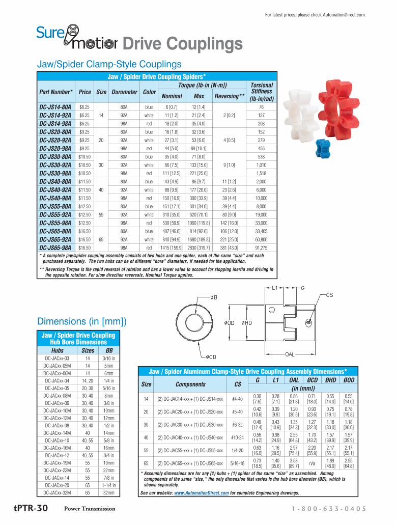
Jaw/Spider Clamp-Style Couplings
Drive Couplings
Jaw / Spider Drive Coupling Spiders*
Part Number* Price Size Durometer ColorTorque (lb·in [N·m]) Torsional
Stiffness(lb·in/rad)Nominal Max Reversing**
DC-JS14-80A $6.25
14
80A blue 6 [0.7] 12 [1.4]
2 [0.2]
76
DC-JS14-92A $6.25 92A white 11 [1.2] 21 [2.4] 127
DC-JS14-98A $6.25 98A red 18 [2.0] 35 [4.0] 203
DC-JS20-80A $9.25
20
80A blue 16 [1.8] 32 [3.6]
4 [0.5]
152
DC-JS20-92A $9.25 92A white 27 [3.1] 53 [6.0] 279
DC-JS20-98A $9.25 98A red 44 [5.0] 89 [10.1] 456
DC-JS30-80A $10.50
30
80A blue 35 [4.0] 71 [8.0]
9 [1.0]
538
DC-JS30-92A $10.50 92A white 66 [7.5] 133 [15.0] 1,010
DC-JS30-98A $10.50 98A red 111 [12.5] 221 [25.0] 1,518
DC-JS40-80A $11.50
40
80A blue 43 [4.9] 86 [9.7] 11 [1.2] 2,000
DC-JS40-92A $11.50 92A white 88 [9.9] 177 [20.0] 23 [2.6] 6,000
DC-JS40-98A $11.50 98A red 150 [16.9] 300 [33.9] 39 [4.4] 10,000
DC-JS55-80A $12.50
55
80A blue 151 [17.1] 301 [34.0] 39 [4.4] 8,000
DC-JS55-92A $12.50 92A white 310 [35.0] 620 [70.1] 80 [9.0] 19,000
DC-JS55-98A $12.50 98A red 530 [59.9] 1060 [119.8] 142 [16.0] 33,000
DC-JS65-80A $16.50
65
80A blue 407 [46.0] 814 [92.0] 106 [12.0] 33,405
DC-JS65-92A $16.50 92A white 840 [94.9] 1680 [189.8] 221 [25.0] 60,800
DC-JS65-98A $16.50 98A red 1415 [159.9] 2830 [319.7] 381 [43.0] 91,275* A complete jaw/spider coupling assembly consists of two hubs and one spider, each of the same “size” and each
purchased separately. The two hubs can be of different “bore” diameters, if needed for the application.
** Reversing Torque is the rapid reversal of rotation and has a lower value to account for stopping inertia and driving in the opposite rotation. For slow direction reversals, Nominal Torque applies.
Dimensions (in [mm])
Jaw / Spider Aluminum Clamp-Style Drive Coupling Assembly Dimensions*
Size Components CSG L1 OAL ØCD ØHD ØOD
(in [mm])
14 (2) DC-JAC14-xxx + (1) DC-JS14-xxx #4-40 0.30 [7.6]
0.28 [7.1]
0.86 [21.8]
0.71 [18.0]
0.55 [14.0]
0.55 [14.0]
20 (2) DC-JAC20-xxx + (1) DC-JS20-xxx #5-40 0.42 [10.6]
0.39 [9.9]
1.20 [30.5]
0.93 [23.6]
0.75 [19.1]
0.78 [19.8]
30 (2) DC-JAC30-xxx + (1) DC-JS30-xxx #6-32 0.49 [12.4]
0.43 [10.9]
1.35 [34.3]
1.27 [32.3]
1.18 [30.0]
1.18 [30.0]
40 (2) DC-JAC40-xxx + (1) DC-JS40-xxx #10-24 0.56 [14.2]
0.98 [24.9]
2.55 [64.8]
1.70 [43.2]
1.57 [39.9]
1.57 [39.9]
55 (2) DC-JAC55-xxx + (1) DC-JS55-xxx 1/4-20 0.63 [16.0]
1.16 [29.5]
2.97 [75.4]
2.20 [55.9]
2.17 [55.1]
2.17 [55.1]
65 (2) DC-JAC65-xxx + (1) DC-JS65-xxx 5/16-18 0.73 [18.5]
1.40 [35.6]
3.53 [89.7] n/a 1.89
[48.0]2.55
[64.8]* Assembly dimensions are for any (2) hubs + (1) spider of the same “size” as assembled. Among
components of the same “size,” the only dimension that varies is the hub bore diameter (ØB), which is shown separately.
See our website: www.AutomationDirect.com for complete Engineering drawings.
Jaw / Spider Drive Coupling Hub Bore DimensionsHubs Sizes ØB
DC-JACxx-03 14 3/16 inDC-JACxx-05M 14 5mmDC-JACxx-06M 14 6mmDC-JACxx-04 14, 20 1/4 inDC-JACxx-05 20, 30 5/16 in
DC-JACxx-08M 30, 40 8mmDC-JACxx-06 30, 40 3/8 in
DC-JACxx-10M 30, 40 10mmDC-JACxx-12M 30, 40 12mmDC-JACxx-08 30, 40 1/2 in
DC-JACxx-14M 40 14mmDC-JACxx-10 40, 55 5/8 in
DC-JACxx-16M 40 16mmDC-JACxx-12 40, 55 3/4 in
DC-JACxx-19M 55 19mmDC-JACxx-22M 55 22mmDC-JACxx-14 55 7/8 inDC-JACxx-20 65 1-1/4 in
DC-JACxx-32M 65 32mm
1 - 8 0 0 - 6 3 3 - 0 4 0 5Power TransmissiontPTR-30
For latest prices, please check AutomationDirect.com.
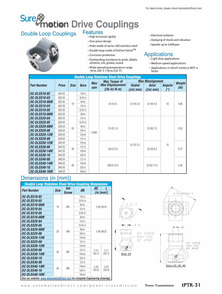
Double Loop CouplingsDrive Couplings
Double Loop Stainless Steel Drive Couplings
Part Number Price Size Bore Maxrpm
Max Torque @ Max Displacement
([lb·in] N·m)
Max Misalignment Weight(lb)
Radial([in] mm)
Axial([in] mm)
Angular(°)
DC-DLSS10-02 $35.50
10
1/8 in
3,000
[4.4] 0.5 [0.10] 2.6 [0.18] 4.5 10 0.06
DC-DLSS10-03 $35.50 3/16 inDC-DLSS10-06M $35.50 6mmDC-DLSS10-04 $35.50 1/4 inDC-DLSS10-05 $35.50 5/16 inDC-DLSS10-08M $35.50 8mmDC-DLSS20-04 $39.50
20
1/4 in
[15.9] 1.8
[0.13] 3.2
[0.30] 7.5
15
0.20
DC-DLSS20-05 $39.50 5/16 inDC-DLSS20-08M $39.50 8mmDC-DLSS20-06 $39.50 3/8 inDC-DLSS20-12M $39.50 12mmDC-DLSS20-08 $39.50 1/2 inDC-DLSS30-12M $43.50
30
12mm
[44.3] 5.0 [0.33] 8.5 0.27DC-DLSS30-08 $43.50 1/2 inDC-DLSS30-14M $43.50 14mmDC-DLSS30-10 $43.50 5/8 inDC-DLSS40-08 $48.50
40
1/2 in
[88.5] 10.0 [0.43] 11.0 0.30DC-DLSS40-14M $48.50 14mmDC-DLSS40-10 $48.50 5/8 inDC-DLSS40-16M $48.50 16mm
Dimensions (in [mm])Double Loop Stainless Steel Drive Coupling Dimensions
Part Number Size SetScrew ØB ØC L
(in [mm])DC-DLSS10-02
10 M3
1/8 in
1.06 [26.9]
DC-DLSS10-03 3/16 inDC-DLSS10-06M 6mmDC-DLSS10-04 1/4 inDC-DLSS10-05 5/16 inDC-DLSS10-08M 8mmDC-DLSS20-04
20 M4
1/4 in
1.89 [48.0]
DC-DLSS20-05 5/16 inDC-DLSS20-08M 8mmDC-DLSS20-06 3/8 inDC-DLSS20-12M 12mmDC-DLSS20-08 1/2 inDC-DLSS30-12M
30 M5
12mm
2.13 [54.1]
2.17 [55.1]
DC-DLSS30-08 1/2 inDC-DLSS30-14M 14mmDC-DLSS30-10 5/8 inDC-DLSS40-08
40 M6
1/2 in
2.20 [55.9]
2.20 [55.9]
DC-DLSS40-14M 14mmDC-DLSS40-10 5/8 inDC-DLSS40-16M 16mmSee our website: www.AutomationDirect.com for complete Engineering drawings.
Features• High torsional rigidity• One-piece design• Hubs made of series 300 stainless steel• Double loop made of DuPont HytrelTM
• Corrosion protection• Outstanding resistance to acids, alkalis,
solvents, oils, grease, ozone• Wide operating temperature range:
-40 to 100 °C (-40 to 212 °F)
• Electrical isolation• Damping of shock and vibration• Speeds up to 3,000rpm
Applications• Light-duty applications• Medium-speed applications• Applications in which inertia is NOT a
factor
Size 10
Sizes 20, 30, 40
Power Transmissionw w w . a u t o m a t i o n d i r e c t . c o m / p o w e r - t r a n s m i s s i o n tPTR-31
For latest prices, please check AutomationDirect.com.
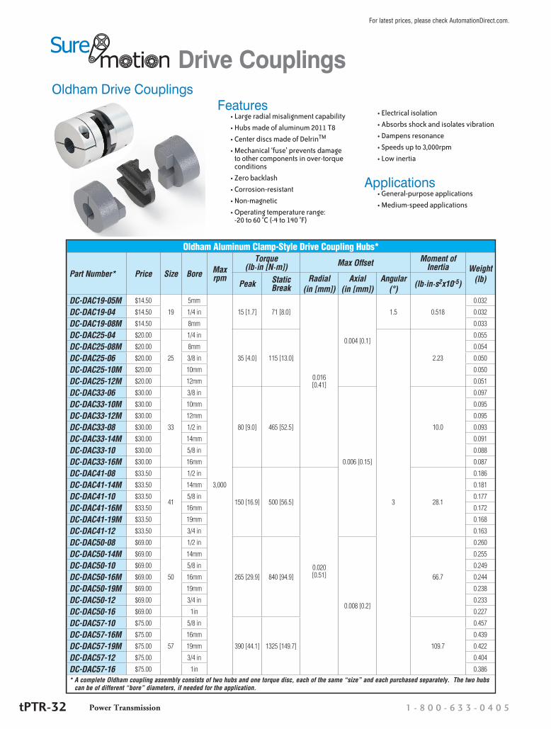
Oldham Drive Couplings
Drive Couplings
Oldham Aluminum Clamp-Style Drive Coupling Hubs*
Part Number* Price Size Bore Max rpm
Torque (lb·in [N·m]) Max Offset Moment of
Inertia Weight(lb)Peak Static
BreakRadial
(in [mm])Axial
(in [mm])Angular
(°) (lb·in·s2x10-5)
DC-DAC19-05M $14.50
19
5mm
3,000
15 [1.7] 71 [8.0]
0.016 [0.41]
0.004 [0.1]
1.5 0.518
0.032
DC-DAC19-04 $14.50 1/4 in 0.032
DC-DAC19-08M $14.50 8mm 0.033
DC-DAC25-04 $20.00
25
1/4 in
35 [4.0] 115 [13.0]
3
2.23
0.055
DC-DAC25-08M $20.00 8mm 0.054
DC-DAC25-06 $20.00 3/8 in 0.050
DC-DAC25-10M $20.00 10mm 0.050
DC-DAC25-12M $20.00 12mm 0.051
DC-DAC33-06 $30.00
33
3/8 in
80 [9.0] 465 [52.5]
0.006 [0.15]
10.0
0.097
DC-DAC33-10M $30.00 10mm 0.095
DC-DAC33-12M $30.00 12mm 0.095
DC-DAC33-08 $30.00 1/2 in 0.093
DC-DAC33-14M $30.00 14mm 0.091
DC-DAC33-10 $30.00 5/8 in 0.088
DC-DAC33-16M $30.00 16mm 0.087
DC-DAC41-08 $33.50
41
1/2 in
150 [16.9] 500 [56.5]
0.020 [0.51]
28.1
0.186
DC-DAC41-14M $33.50 14mm 0.181
DC-DAC41-10 $33.50 5/8 in 0.177
DC-DAC41-16M $33.50 16mm 0.172
DC-DAC41-19M $33.50 19mm 0.168
DC-DAC41-12 $33.50 3/4 in 0.163
DC-DAC50-08 $69.00
50
1/2 in
265 [29.9] 840 [94.9]
0.008 [0.2]
66.7
0.260
DC-DAC50-14M $69.00 14mm 0.255
DC-DAC50-10 $69.00 5/8 in 0.249
DC-DAC50-16M $69.00 16mm 0.244
DC-DAC50-19M $69.00 19mm 0.238
DC-DAC50-12 $69.00 3/4 in 0.233
DC-DAC50-16 $69.00 1in 0.227
DC-DAC57-10 $75.00
57
5/8 in
390 [44.1] 1325 [149.7] 109.7
0.457
DC-DAC57-16M $75.00 16mm 0.439
DC-DAC57-19M $75.00 19mm 0.422
DC-DAC57-12 $75.00 3/4 in 0.404
DC-DAC57-16 $75.00 1in 0.386* A complete Oldham coupling assembly consists of two hubs and one torque disc, each of the same “size” and each purchased separately. The two hubs
can be of different “bore” diameters, if needed for the application.
Features• Large radial misalignment capability• Hubs made of aluminum 2011 T8• Center discs made of DelrinTM
• Mechanical ‘fuse’ prevents damage to other components in over-torque conditions
• Zero backlash• Corrosion-resistant• Non-magnetic• Operating temperature range:
-20 to 60 °C (-4 to 140 °F)
• Electrical isolation• Absorbs shock and isolates vibration• Dampens resonance• Speeds up to 3,000rpm• Low inertia
Applications• General-purpose applications• Medium-speed applications
1 - 8 0 0 - 6 3 3 - 0 4 0 5Power TransmissiontPTR-32
For latest prices, please check AutomationDirect.com.

Oldham Drive Couplings
Drive Couplings
Oldham Aluminum Clamp-Style Drive Coupling Torque Discs*
Part Number* Price Size Color
DC-DDS19 $2.00 19
black
DC-DDS25 $3.75 25
DC-DDS33 $7.50 33
DC-DDS41 $8.25 41
DC-DDS50 $18.00 50
DC-DDS57 $26.00 57* A complete Oldham coupling assembly
consists of two hubs and one torque disc, each of the same “size” and each purchased separately. The two hubs can be of different “bore” diameters, if needed for the application.
Dimensions (in [mm])
Oldham Aluminum Clamp-Style Drive Coupling Assembly Dimensions*
Size Components Cap Screw
C L1 ØOD(in [mm])
19 (2) DC-DAC19-xxx + (1) DC-DDS19 #4-40 0.37 [9.4]
1.02 [25.9]
0.75 [19.1]
25 (2) DC-DAC25-xxx + (1) DC-DDS25 M3 0.46 [11.7]
1.28 [32.5]
1.00 [25.4]
33 (2) DC-DAC33-xxx + (1) DC-DDS33 M4 0.59 [15.0]
1.89 [48.0]
1.31 [33.3]
41 (2) DC-DAC41-xxx + (1) DC-DDS41 M4 0.70 [17.8]
2.00 [50.8]
1.63 [41.4]
50 (2) DC-DAC50-xxx + (1) DC-DDS50 M5 0.81 [20.6]
2.35 [59.7]
1.97 [50.0]
57 (2) DC-DAC57-xxx + (1) DC-DDS57 M6 1.12 [28.4]
3.07 [78.0]
2.25 [57.2]
* Assembly dimensions are for any (2) hubs + (1) torque disc of the same “size” as assembled. Among components of the same “size,” the only dimension that varies is the hub bore diameter (ØB), which is shown separately.
See our website: www.AutomationDirect.com for complete Engineering drawings.
Oldham Aluminum Drive Coupling Hub Bore Dimensions
Hubs Sizes ØBDC-DACxx-05M 19 5mmDC-DACxx-04 19, 25 1/4 in
DC-DACxx-08M 19, 25 8mmDC-DACxx-06 25, 33 3/8 in
DC-DACxx-10M 25, 33 10mmDC-DACxx-12M 25, 33 12mmDC-DACxx-08 33, 41, 50 1/2 in
DC-DACxx-14M 33, 41, 50 14mmDC-DACxx-10 33, 41, 50, 57 5/8 in
DC-DACxx-16M 33, 41, 50, 57 16mmDC-DACxx-12 41, 50, 57 3/4 in
DC-DACxx-19M 41, 50, 57 19mmDC-DACxx-16 50, 57 1in
Power Transmissionw w w . a u t o m a t i o n d i r e c t . c o m / p o w e r - t r a n s m i s s i o n tPTR-33
For latest prices, please check AutomationDirect.com.

Beam-Style Servo Stainless Steel Set-Screw Couplings
Drive Couplings
Beam-Style Servo Stainless Steel* Set-Screw Drive Coupling Hubs
Part Number Price Size Bore** Max rpm
Torsional Stiffness(lb·in/°)
Max Torque Max Misalignment Moment of Inertia
(lb·in·s2x10-5)
Weight(oz)(lb·in [N·m]) Radial
(in [mm])Axial
(in [mm])Angular
(°)DC-SBS19-0404 $43.50 19 1/4 in 10,000 11 12 [1.4] 0.010 [0.25] 0.020 [0.51]
7
0.86 0.84
DC-SBS25-0808 $55.00 25 1/2 in7,500
27 24 [2.7]0.015 [0.38]
0.025 [0.64] 3.75 1.60
DC-SBS32-1010 $60.00 32 5/8 in 51 48 [5.4]0.030 [0.76]
11.1 2.45
DC-SBS38-1212 $68.00 38 3/4 in5,000
89 75 [8.5]0.020 [0.51]
28.2 4.94
DC-SBS44-1414 $117.00 44 7/8 in 135 135 [15.3] 0.040 [1.02] 59.2 7.59
DC-SBS51-1616 $136.00 51 1in3,750
205 180 [20.3]0.025 [0.64]
0.050 [1.27] 115 11.26
DC-SBS63-2020 $156.00 63 1-1/4 in 395 300 [33.9] 0.060 [1.52] 349 18.67* Hubs are 416 stainless; flex beams are 420 stainless.
** Bore Reducers can be purchased separately from AutomationDirect and installed in DC-SBSxx-xxxx hubs if different bore sizes are needed. (See page tPTR-35 for Bore Reducers.)
Dimensions (in [mm])Beam-Style Servo Stainless Steel Drive Coupling
Dimensions
Size Set Screw
L L1 ØB1* ØB2* ØOD(in [mm])
19M3x0.5
0.75 [19.1] 0.240 [6.10] 0.250 [6.35] 0.75 [19.1]25 1.00 [25.4] 0.345 [8.76] 0.500 [12.70] 1.00 [25.4]32
M5x0.8
1.25 [31.6] 0.386 [9.80] 0.625 [15.88] 1.25 [31.6]38 1.50 [38.1] 0.505 [12.83] 0.750 [19.05] 1.50 [38.1]44 1.75 [44.5] 0.550 [13.97] 0.875 [22.23] 1.75 [44.5]51 2.00 [50.8] 0.555 [14.10] 1.000 [25.40] 2.00 [50.8]63 M6x1.0 2.50 [63.5] 0.615 [15.62] 1.250 [31.75] 2.50 [63.5]
* Use bore reducers for additional bore sizes and bore combinations.
See our website: www.AutomationDirect.com for complete Engineering drawings.
Features• Flexibility of bellows coupling plus
torsional stiffness and strength of disc coupling
• Hubs made of 416 stainless steel• Flex beams made of 420 stainless steel• Zero backlash• Corrosion-resistant• Bore reducers available to fit a wide vari-
ety of bore combinations• Very wide operating temperature range:
for 24/7 applications: -73 to 191 °C (-100 to 375 °F) for intermittent applications (<8hr): -73 to 232 °C (-100 to 450 °F)
• Speeds up to 10,000rpm• Torque up to 300 lb·in
Applications• High performance applications• High-speed applications• High-torque applications
1 - 8 0 0 - 6 3 3 - 0 4 0 5Power TransmissiontPTR-34
For latest prices, please check AutomationDirect.com.

Accessories – Bore ReducersDrive Couplings
Features• For use in all SureMotion drive coupling hubs to reduce bore size• Split-collar design with 2 set screw flats will not mark shaft• 25% greater holding power than standard split collar• Hardened stainless steel
Bore Reducers – Stainless Steel Clamping Type
Part Number PriceOutside Diameter Inside Diameter
LengthNominal Actual Nominal Actual
DC-BRS04-02 $7.25
1/4 in 0.250 in
1/8 in 0.125 in
0.221 inDC-BRS04-04M $7.25 4mm 4mm
DC-BRS04-03 $7.25 3/16 in 0.1875 in
DC-BRS04-05M $7.25 5mm 5mm
DC-BRS08-06M $9.75
1/2 in 0.500 in
6mm 6mm
0.449 in
DC-BRS08-04 $9.75 1/4 in 0.25 in
DC-BRS08-05 $9.75 5/16 in 0.3125 in
DC-BRS08-08M $9.75 8mm 8mm
DC-BRS08-06 $9.75 3/8 in 0.375 in
DC-BRS08-10M $9.75 10mm 10mm
DC-BRS10-10M $11.00
5/8 in 0.625 in
10mm 10mm
0.460 in
DC-BRS10-07 $11.00 7/16 in 0.4375 in
DC-BRS10-12M $11.00 12mm 12mm
DC-BRS10-08 $11.00 1/2 in 0.5 in
DC-BRS10-14M $11.00 14mm 14mm
DC-BRS10-09 $11.00 9/16 in 0.5625 in
DC-BRS12-06 $13.00
3/4 in 0.750 in
3/8 in 0.375 in
0.646 in
DC-BRS12-12M $13.00 12mm 12mm
DC-BRS12-08 $13.00 1/2 in 0.5 in
DC-BRS12-10 $13.00 5/8 in 0.625 in
DC-BRS12-16M $13.00 16mm 16mm
DC-BRS12-11 $13.00 11/16 in 0.6875 in
DC-BRS14-14M $14.00
7/8 in 0.875 in
14mm 14mm
0.755 in
DC-BRS14-10 $14.00 5/8 in 0.625 in
DC-BRS14-16M $14.00 16mm 16mm
DC-BRS14-11 $14.00 11/16 in 0.6875 in
DC-BRS14-18M $14.00 18mm 18mm
DC-BRS14-12 $14.00 3/4 in 0.75 in
DC-BRS16-10 $14.50
1in 1.000 in
5/8 in 0.625 in
0.773 in
DC-BRS16-18M $14.50 18mm 18mm
DC-BRS16-12 $14.50 3/4 in 0.75 in
DC-BRS16-20M $14.50 20mm 20mm
DC-BRS16-13 $14.50 13/16 in 0.8125 in
DC-BRS16-14 $14.50 7/8 in 0.875 in
DC-BRS20-22M $15.00
1-1/4 in 1.250 in
22mm 22mm
0.793 in
DC-BRS20-24M $15.00 24mm 24mm
DC-BRS20-25M $15.00 25mm 25mm
DC-BRS20-16 $15.00 1in 1.0 in
DC-BRS20-17 $15.00 1-1/16 in 1.0625 in
DC-BRS20-18 $15.00 1-1/8 in 1.125 in
Power Transmissionw w w . a u t o m a t i o n d i r e c t . c o m / p o w e r - t r a n s m i s s i o n tPTR-35
For latest prices, please check AutomationDirect.com.
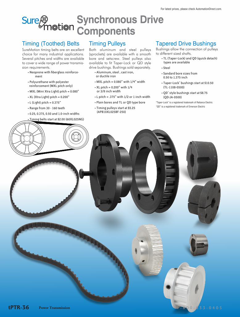
Synchronous Drive Components
Timing (Toothed) BeltsSureMotion timing belts are an excellent choice for many industrial applications. Several pitches and widths are available to cover a wide range of power transmis-sion requirements.
• Neoprene with fiberglass reinforce-ment
• Polyurethane with polyester reinforcement (MXL pitch only)
• MXL (Mini Xtra Light) pitch = 0.080”
• XL (Xtra Light) pitch = 0.200”
• L (Light) pitch = 0.375”
• Range from 30 - 160 teeth
• 0.25, 0.375, 0.50 and 1.0-inch widths
• Timing belts start at $2.00 (60XL025NG)
Timing PulleysBoth aluminum and steel pulleys (sprockets) are available with a smooth bore and setscrew. Steel pulleys also available to fit Taper-Lock or QD style drive bushings. Bushings sold separately.
• Aluminum, steel , cast iron, or ductile iron
• MXL pitch = 0.080” with 1/4” width
• XL pitch = 0.200” with 1/4 or 3/8 inch width
• L pitch = .375” with 1/2 or 1 inch width
• Plain bores and TL or QD type bore
• Timing pulleys start at $5.25 (APB10XL025BF-250)
Tapered Drive Bushings Bushings allow the connection of pulleys to different sized shafts.
• TL (Taper-Lock) and QD (quick detach) types are available
• Steel
• Sandard bore sizes from 0.50 to 1.375 inch
• Taper-Lock® bushings start at $10.50 (TL-1108-0500)
• QD® style bushings start at $8.75 (QD-JA-0500)
“Taper-Lock” is a registered trademark of Reliance Electric
“QD” is a registered trademark of Emerson Electric
1 - 8 0 0 - 6 3 3 - 0 4 0 5Power TransmissiontPTR-36
For latest prices, please check AutomationDirect.com.

Timing Pulleys Bushings Timing Belts
Timing pulleys, bushings, and belts allow you to change speed and torque while connecting mechanically rotating components.
• Select pulley sizes in order to accomplish the speed or torque change that you need.
• Bushings allow you to connect the same pulleys to different sized shafts, or vice versa.
• Synchronous drive belts and pulleys utilize teeth to prevent slippage and unwanted speed variations.
Note: For pulley speeds in excess of 6,000 RPM, pulleys should be dynamically balanced.
Product Overview
Drive Component Selection1. Determine required torque (ft·lbs) and rpm of driven shaft.
2. Determine design horsepower:
3. Determine Pitch (MXL XL or L) and belt width required by reading Design Horsepower Chart.
4. Select driver and driven pulleys to match desired speed or torque change.
5. Determine belt length per belt length calculation.
Note: AutomationDirect provides an online configuration tool to assist with pulley and belt sizing. See: www.automationdirect.com/selectors/beltandpulley
Service FactorsMachine Type <8hr per day 8-16 hr per day Continuous
Smooth Running 1.0 1.2 1.4
Light Shock Loads 1.3 1.5 1.7
Heavy Shock Loads 1.7 1.9 2.1
Where: T = torque (ft·lb)N = rpmsf = service factor per table
DHP = T • N • sf5,252
Pitch (Circular Pitch)
BeltPitchLine
SprocketPitchCircle
DiameterDiameterOutsidePitch
BeltTooth
Pulley Groove
Synchronous Drive Components
Power Transmissionw w w . a u t o m a t i o n d i r e c t . c o m / p o w e r - t r a n s m i s s i o n tPTR-37
For latest prices, please check AutomationDirect.com.
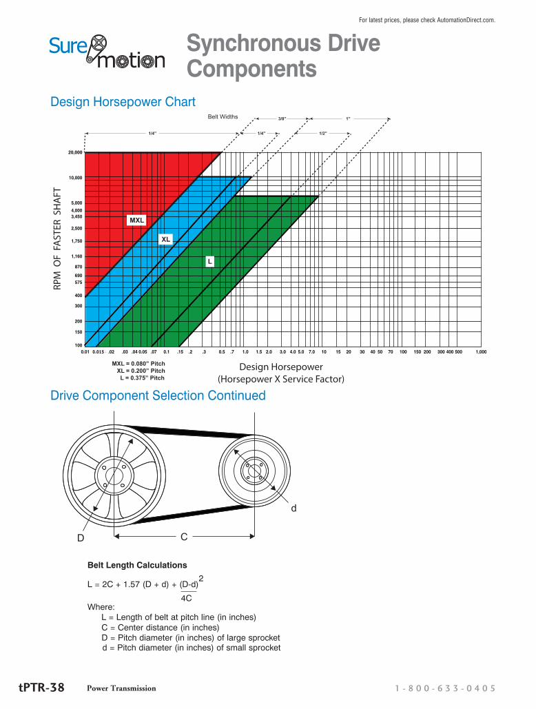
Belt Length Calculations
Where:L = Length of belt at pitch line (in inches)C = Center distance (in inches)D = Pitch diameter (in inches) of large sprocketd = Pitch diameter (in inches) of small sprocket
L = 2C + 1.57 (D + d) + (D-d)2
4C
D C
d
Drive Component Selection Continued
RPM
OF
FA
STER
SH
AFT
Design Horsepower(Horsepower X Service Factor)
1/4”1/4”
3/8”
1/2”
1”Belt Widths
MXL = 0.080” Pitch XL = 0.200” Pitch L = 0.375” Pitch
0.015
XL
L
MXL
20,000
Design Horsepower Chart
Synchronous Drive Components
1 - 8 0 0 - 6 3 3 - 0 4 0 5Power TransmissiontPTR-38
For latest prices, please check AutomationDirect.com.

MXL Synchronous Timing Belt PulleysAlso referred to as sprockets, SureMotion MXL timing pulleys have a 0.080 inch pitch and 1/4 inch width. Aluminum pulleys are available with a smooth bore and setscrews.
Timing Belt Pulleys – Pitch Designation XL; Plain Bore (With Hub)
Part Number Pric
e
Wei
ght (
lb)
# Gr
oove
s (T
eeth
)
Nom
inal
Wid
th (i
n)
Flan
ge (Y
/N)
Pitc
h (in
)
Pitc
h Di
amet
er (i
n)
Bore
Dia
met
er
Mat
eria
l*
Part Number Pric
e
Wei
ght (
lb)
# Gr
oove
s (T
eeth
)
Nom
inal
Wid
th (i
n)
Flan
ge (Y
/N)
Pitc
h (in
)
Pitc
h Di
amet
er (i
n)
Bore
Dia
met
er
Mat
eria
l*APB10MXL025CF-125 $8.00 0.1 10 0.25 Y 0.08 0.255 0.125 Al APB28MXL025BF-250 $9.75 0.1 28 0.25 Y 0.08 0.713 0.25 Al
APB11MXL025CF-125 $7.75 0.1 11 0.25 Y 0.08 0.280 0.125 Al APB30MXL025BF-250 $10.50 0.1 30 0.25 Y 0.08 0.764 0.25 Al
APB12MXL025CF-125 $8.25 0.1 12 0.25 Y 0.08 0.306 0.125 Al APB32MXL025BF-250 $10.50 0.1 32 0.25 Y 0.08 0.815 0.25 Al
APB14MXL025CF-125 $8.50 0.1 14 0.25 Y 0.08 0.357 0.125 Al APB36MXL025BF-250 $10.50 0.1 36 0.25 Y 0.08 0.917 0.25 Al
APB15MXL025CF-188 $8.50 0.1 15 0.25 Y 0.08 0.382 0.1875 Al APB40MXL025BF-250 $11.50 0.1 40 0.25 Y 0.08 1.019 0.25 Al
APB16MXL025CF-188 $8.75 0.1 16 0.25 Y 0.08 0.407 0.1875 Al APB42MXL025BF-250 $12.00 0.1 42 0.25 Y 0.08 1.070 0.25 Al
APB18MXL025BF-188 $8.75 0.1 18 0.25 Y 0.08 0.458 0.1875 Al APB44MXL025BF-250 $12.00 0.1 44 0.25 Y 0.08 1.120 0.25 Al
APB18MXL025CF-250 $8.75 0.1 18 0.25 Y 0.08 0.458 0.25 Al APB48MXL025BF-250 $14.00 0.1 48 0.25 Y 0.08 1.222 0.25 Al
APB20MXL025BF-188 $8.75 0.1 20 0.25 Y 0.08 0.509 0.1875 Al APB60MXL025BF-250 $15.50 0.1 60 0.25 Y 0.08 1.528 0.25 Al
APB20MXL025CF-250 $9.25 0.1 20 0.25 Y 0.08 0.509 0.25 Al APB60MXL025B-250 $15.50 0.1 60 0.25 N 0.08 1.528 0.25 Al
APB21MXL025BF-188 $8.75 0.1 21 0.25 Y 0.08 0.535 0.1875 Al APB72MXL025B-250 $17.00 0.1 72 0.25 N 0.08 1.833 0.25 Al
APB21MXL025CF-250 $9.50 0.1 21 0.25 Y 0.08 0.535 0.25 Al APB80MXL025B-312 $20.00 0.1 80 0.25 N 0.08 2.037 0.3125 Al
APB22MXL025BF-188 $9.00 0.1 22 0.25 Y 0.08 0.560 0.1875 Al APB90MXL025B-312 $23.50 0.1 90 0.25 N 0.08 2.292 0.3125 Al
APB22MXL025CF-250 $9.75 0.1 22 0.25 Y 0.08 0.560 0.25 Al APB100MXL025B-312 $27.00 0.1 100 0.25 N 0.08 2.546 0.3125 Al
APB24MXL025BF-250 $9.25 0.1 24 0.25 Y 0.08 0.611 0.25 Al APB120MXL025B-375 $30.50 0.1 120 0.25 N 0.08 3.056 0.375 Al
APB25MXL025BF-250 $9.50 0.1 25 0.25 Y 0.08 0.637 0.25 Al
* Al = Aluminum; S = Steel
MXL Pulley with Hub, No Flange
MXL Pulley with Hub and Flange
MXL Pulley with Oversize Hub and Flange
Synchronous Drive Components
Power Transmissionw w w . a u t o m a t i o n d i r e c t . c o m / p o w e r - t r a n s m i s s i o n tPTR-39
For latest prices, please check AutomationDirect.com.

XL Synchronous Timing Belt PulleysAlso referred to as sprockets, SureMotion XL timing pulleys have a 1/5 inch pitch and 1/4 or 3/8 inch width. Both aluminum and steel pulleys are available with a smooth bore and setscrews.
Timing Belt Pulleys – Pitch Designation XL; Plain Bore (With Hub)
Part Number Pric
e
Wei
ght (
lb)
# Gr
oove
s (T
eeth
)
Nom
inal
Wid
th (i
n)
Flan
ge (Y
/N)
Pitc
h (in
)
Pitc
h Di
amet
er (i
n)
Bore
Dia
met
erM
ater
ial*
Part Number Pric
e
Wei
ght (
lb)
# Gr
oove
s (T
eeth
)
Nom
inal
Wid
th (i
n)
Flan
ge (Y
/N)
Pitc
h (in
)
Pitc
h Di
amet
er (i
n)
Bore
Dia
met
er
Mat
eria
l*
APB10XL025BF-250 $6.50 0.1 10 0.25 Y 0.20 0.637 0.25 Al APB18XL037BF-250 $9.25 0.1 18 0.375 Y 0.20 1.146 0.25 Al
APB11XL025BF-250 $7.50 0.1 11 0.25 Y 0.20 0.700 0.25 Al APB19XL037BF-250 $9.75 0.1 19 0.375 Y 0.20 1.210 0.25 Al
APB12XL025BF-250 $6.75 0.1 12 0.25 Y 0.20 0.764 0.25 Al APB20XL037BF-250 $10.00 0.1 20 0.375 Y 0.20 1.273 0.25 Al
APB13XL025BF-250 $7.25 0.1 13 0.25 Y 0.20 0.828 0.25 Al APB21XL037BF-250 $11.50 0.1 21 0.375 Y 0.20 1.337 0.25 Al
APB14XL025BF-250 $8.00 0.1 14 0.25 Y 0.20 0.891 0.25 Al APB22XL037BF-250 $12.00 0.1 22 0.375 Y 0.20 1.401 0.25 Al
APB15XL025BF-250 $9.25 0.1 15 0.25 Y 0.20 0.955 0.25 Al APB23XL037BF-250 $12.50 0.1 23 0.375 Y 0.20 1.464 0.25 Al
APB16XL025BF-250 $9.75 0.1 16 0.25 Y 0.20 1.019 0.25 Al APB24XL037BF-250 $13.00 0.1 24 0.375 Y 0.20 1.528 0.25 Al
APB18XL025BF-250 $9.00 0.1 18 0.25 Y 0.20 1.146 0.25 Al APB25XL037BF-250 $14.00 0.1 25 0.375 Y 0.20 1.592 0.25 Al
APB20XL025BF-250 $9.50 0.1 20 0.25 Y 0.20 1.273 0.25 Al APB26XL037BF-250 $14.00 0.1 26 0.375 Y 0.20 1.655 0.25 Al
APB21XL025BF-250 $11.00 0.1 21 0.25 Y 0.20 1.337 0.25 Al APB28XL037BF-250 $14.50 0.2 28 0.375 Y 0.20 1.783 0.25 Al
APB22XL025BF-250 $11.50 0.1 22 0.25 Y 0.20 1.401 0.25 Al APB30XL037BF-250 $16.00 0.2 30 0.375 Y 0.20 1.910 0.25 Al
APB24XL025BF-250 $12.00 0.1 24 0.25 Y 0.20 1.528 0.25 Al APB32XL037BF-312 $16.00 0.2 32 0.375 Y 0.20 2.037 0.312 Al
APB26XL025BF-250 $13.00 0.1 26 0.25 Y 0.20 1.655 0.25 Al APB32XL037B-312 $17.50 0.2 32 0.375 N 0.20 2.037 0.312 Al
APB28XL025BF-250 $14.50 0.1 28 0.25 Y 0.20 1.783 0.25 Al APB36XL037B-312 $20.00 0.3 36 0.375 N 0.20 2.292 0.312 Al
APB30XL025BF-250 $16.00 0.2 30 0.25 Y 0.20 1.910 0.25 Al APB40XL037B-312 $21.50 0.4 40 0.375 N 0.20 2.546 0.312 Al
APB10XL037BF-250 $6.75 0.1 10 0.375 Y 0.20 0.637 0.25 Al APB42XL037B-312 $22.00 0.4 42 0.375 N 0.20 2.674 0.312 Al
APB11XL037BF-250 $7.00 0.1 11 0.375 Y 0.20 0.700 0.25 Al APB44XL037B-312 $24.50 0.4 44 0.375 N 0.20 2.801 0.312 Al
APB12XL037BF-250 $7.25 0.1 12 0.375 Y 0.20 0.764 0.25 Al APB48XL037B-312 $26.00 0.5 48 0.375 N 0.20 3.056 0.312 Al
APB13XL037BF-250 $7.75 0.1 13 0.375 Y 0.20 0.828 0.25 Al APB60XL037B-375 $29.00 0.6 60 0.375 N 0.20 3.820 0.375 Al
APB14XL037BF-250 $8.25 0.1 14 0.375 Y 0.20 0.891 0.25 Al APB72XL037B-375 $31.50 0.9 72 0.375 N 0.20 4.584 0.375 Al
APB15XL037BF-250 $8.50 0.1 15 0.375 Y 0.20 0.955 0.25 Al SPB28XL037BF-250 $17.50 0.5 28 0.375 Y 0.20 1.783 0.25 S
APB16XL037BF-250 $9.00 0.1 16 0.375 Y 0.20 1.019 0.25 Al SPB30XL037BF-312 $16.00 0.6 30 0.375 Y 0.20 1.910 0.312 S
APB17XL037BF-250 $9.25 0.1 17 0.375 Y 0.20 1.082 0.25 Al
* Al = Aluminum; S = Steel
XL Pulley with Hub, No Flange
XL Pulley with Hub and Flange
Synchronous Drive Components
1 - 8 0 0 - 6 3 3 - 0 4 0 5Power TransmissiontPTR-40
For latest prices, please check AutomationDirect.com.
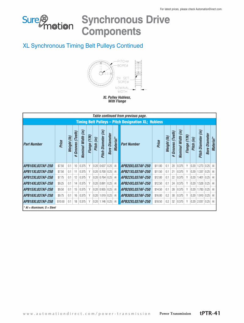
Table continued from previous page.
Timing Belt Pulleys – Pitch Designation XL; Hubless
Part Number Pric
e
Wei
ght (
lb)
# Gr
oove
s (T
eeth
)
Nom
inal
Wid
th (i
n)
Flan
ge (Y
/N)
Pitc
h (in
)
Pitc
h Di
amet
er (i
n)
Bore
Dia
met
erM
ater
ial*
Part Number Pric
e
Wei
ght (
lb)
# Gr
oove
s (T
eeth
)
Nom
inal
Wid
th (i
n)
Flan
ge (Y
/N)
Pitc
h (in
)
Pitc
h Di
amet
er (i
n)
Bore
Dia
met
erM
ater
ial*
APB10XL037AF-250 $7.50 0.1 10 0.375 Y 0.20 0.637 0.25 Al APB20XL037AF-250 $11.00 0.1 20 0.375 Y 0.20 1.273 0.25 Al
APB11XL037AF-250 $7.50 0.1 11 0.375 Y 0.20 0.700 0.25 Al APB21XL037AF-250 $11.50 0.1 21 0.375 Y 0.20 1.337 0.25 Al
APB12XL037AF-250 $7.75 0.1 12 0.375 Y 0.20 0.764 0.25 Al APB22XL037AF-250 $12.00 0.1 22 0.375 Y 0.20 1.401 0.25 Al
APB14XL037AF-250 $9.25 0.1 14 0.375 Y 0.20 0.891 0.25 Al APB24XL037AF-250 $12.50 0.1 24 0.375 Y 0.20 1.528 0.25 Al
APB15XL037AF-250 $9.50 0.1 15 0.375 Y 0.20 0.955 0.25 Al APB28XL037AF-250 $14.50 0.1 28 0.375 Y 0.20 1.783 0.25 Al
APB16XL037AF-250 $9.75 0.1 16 0.375 Y 0.20 1.019 0.25 Al APB30XL037AF-250 $16.00 0.2 30 0.375 Y 0.20 1.910 0.25 Al
APB18XL037AF-250 $10.50 0.1 18 0.375 Y 0.20 1.146 0.25 Al APB32XL037AF-250 $18.50 0.2 32 0.375 Y 0.20 2.037 0.25 Al
* Al = Aluminum; S = Steel
XL Synchronous Timing Belt Pulleys Continued
XL Pulley Hubless, With Flange
Synchronous Drive Components
Power Transmissionw w w . a u t o m a t i o n d i r e c t . c o m / p o w e r - t r a n s m i s s i o n tPTR-41
For latest prices, please check AutomationDirect.com.
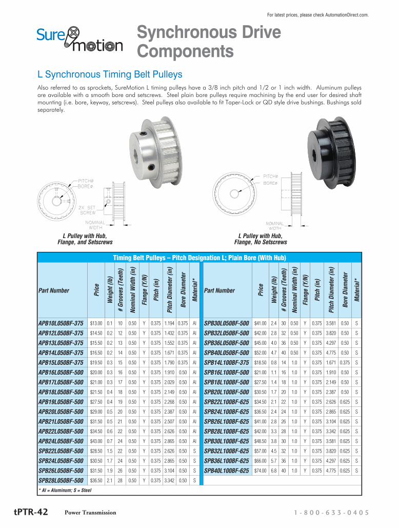
L Synchronous Timing Belt Pulleys
Timing Belt Pulleys – Pitch Designation L; Plain Bore (With Hub)
Part Number Pric
e
Wei
ght (
lb)
# Gr
oove
s (T
eeth
)
Nom
inal
Wid
th (i
n)
Flan
ge (Y
/N)
Pitc
h (in
)
Pitc
h Di
amet
er (i
n)
Bore
Dia
met
er
Mat
eria
l*
Part Number Pric
e
Wei
ght (
lb)
# Gr
oove
s (T
eeth
)
Nom
inal
Wid
th (i
n)
Flan
ge (Y
/N)
Pitc
h (in
)
Pitc
h Di
amet
er (i
n)
Bore
Dia
met
er
Mat
eria
l*
APB10L050BF-375 $13.00 0.1 10 0.50 Y 0.375 1.194 0.375 Al SPB30L050BF-500 $41.00 2.4 30 0.50 Y 0.375 3.581 0.50 S
APB12L050BF-375 $14.50 0.2 12 0.50 Y 0.375 1.432 0.375 Al SPB32L050BF-500 $42.00 2.8 32 0.50 Y 0.375 3.820 0.50 S
APB13L050BF-375 $15.50 0.2 13 0.50 Y 0.375 1.552 0.375 Al SPB36L050BF-500 $45.00 4.0 36 0.50 Y 0.375 4.297 0.50 S
APB14L050BF-375 $16.50 0.2 14 0.50 Y 0.375 1.671 0.375 Al SPB40L050BF-500 $52.00 4.7 40 0.50 Y 0.375 4.775 0.50 S
APB15L050BF-375 $19.50 0.3 15 0.50 Y 0.375 1.790 0.375 Al SPB14L100BF-375 $18.50 0.8 14 1.0 Y 0.375 1.671 0.375 S
APB16L050BF-500 $20.00 0.3 16 0.50 Y 0.375 1.910 0.50 Al SPB16L100BF-500 $21.00 1.1 16 1.0 Y 0.375 1.910 0.50 S
APB17L050BF-500 $21.00 0.3 17 0.50 Y 0.375 2.029 0.50 Al SPB18L100BF-500 $27.50 1.4 18 1.0 Y 0.375 2.149 0.50 S
APB18L050BF-500 $21.50 0.4 18 0.50 Y 0.375 2.149 0.50 Al SPB20L100BF-500 $30.50 1.7 20 1.0 Y 0.375 2.387 0.50 S
APB19L050BF-500 $27.50 0.4 19 0.50 Y 0.375 2.268 0.50 Al SPB22L100BF-625 $34.50 2.1 22 1.0 Y 0.375 2.626 0.625 S
APB20L050BF-500 $29.00 0.5 20 0.50 Y 0.375 2.387 0.50 Al SPB24L100BF-625 $36.50 2.4 24 1.0 Y 0.375 2.865 0.625 S
APB21L050BF-500 $31.50 0.5 21 0.50 Y 0.375 2.507 0.50 Al SPB26L100BF-625 $41.00 2.8 26 1.0 Y 0.375 3.104 0.625 S
APB22L050BF-500 $34.50 0.6 22 0.50 Y 0.375 2.626 0.50 Al SPB28L100BF-625 $42.00 3.3 28 1.0 Y 0.375 3.342 0.625 S
APB24L050BF-500 $43.00 0.7 24 0.50 Y 0.375 2.865 0.50 Al SPB30L100BF-625 $48.50 3.8 30 1.0 Y 0.375 3.581 0.625 S
SPB22L050BF-500 $28.50 1.5 22 0.50 Y 0.375 2.626 0.50 S SPB32L100BF-625 $57.00 4.5 32 1.0 Y 0.375 3.820 0.625 S
SPB24L050BF-500 $30.50 1.7 24 0.50 Y 0.375 2.865 0.50 S SPB36L100BF-625 $66.00 5.7 36 1.0 Y 0.375 4.297 0.625 S
SPB26L050BF-500 $31.50 1.9 26 0.50 Y 0.375 3.104 0.50 S SPB40L100BF-625 $74.00 6.8 40 1.0 Y 0.375 4.775 0.625 S
SPB28L050BF-500 $36.50 2.1 28 0.50 Y 0.375 3.342 0.50 S
* Al = Aluminum; S = Steel
Also referred to as sprockets, SureMotion L timing pulleys have a 3/8 inch pitch and 1/2 or 1 inch width. Aluminum pulleys are available with a smooth bore and setscrews. Steel plain bore pulleys require machining by the end user for desired shaft mounting (i.e. bore, keyway, setscrews). Steel pulleys also available to fit Taper-Lock or QD style drive bushings. Bushings sold separately.
L Pulley with Hub, Flange, No Setscrews
L Pulley with Hub, Flange, and Setscrews
Synchronous Drive Components
1 - 8 0 0 - 6 3 3 - 0 4 0 5Power TransmissiontPTR-42
For latest prices, please check AutomationDirect.com.
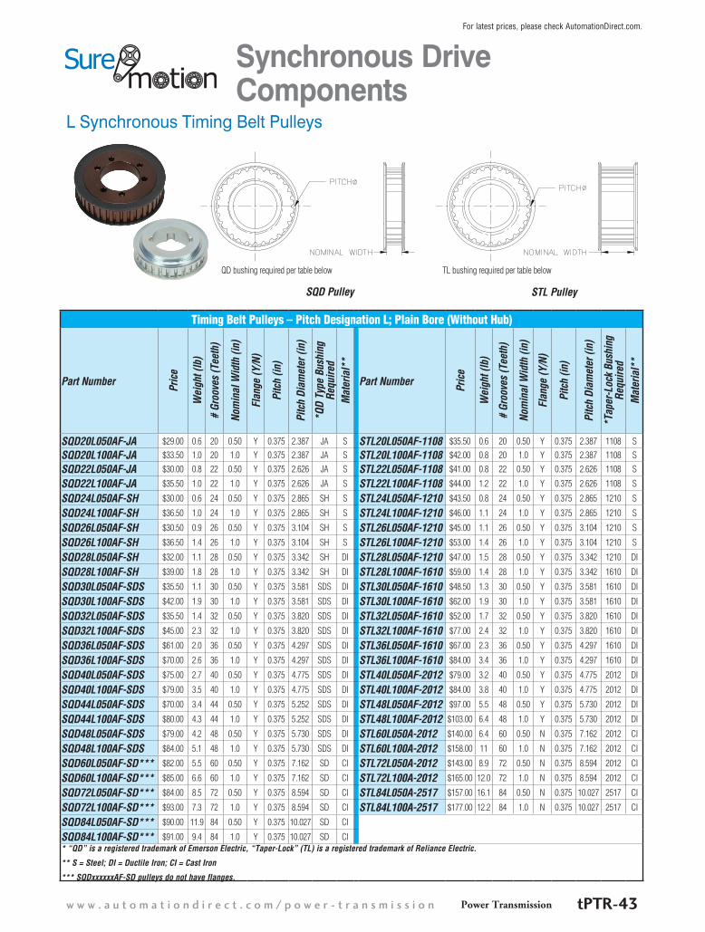
L Synchronous Timing Belt Pulleys
Timing Belt Pulleys – Pitch Designation L; Plain Bore (Without Hub)
Part Number Pric
e
Wei
ght (
lb)
# Gr
oove
s (T
eeth
)
Nom
inal
Wid
th (i
n)
Flan
ge (Y
/N)
Pitc
h (in
)
Pitc
h Di
amet
er (i
n)
*QD
Type
Bus
hing
Re
quire
dM
ater
ial*
*
Part Number Pric
e
Wei
ght (
lb)
# Gr
oove
s (T
eeth
)
Nom
inal
Wid
th (i
n)
Flan
ge (Y
/N)
Pitc
h (in
)
Pitc
h Di
amet
er (i
n)
*Tap
er-L
ock
Bush
ing
Requ
ired
Mat
eria
l**
SQD20L050AF-JA $29.00 0.6 20 0.50 Y 0.375 2.387 JA S STL20L050AF-1108 $35.50 0.6 20 0.50 Y 0.375 2.387 1108 S
SQD20L100AF-JA $33.50 1.0 20 1.0 Y 0.375 2.387 JA S STL20L100AF-1108 $42.00 0.8 20 1.0 Y 0.375 2.387 1108 S
SQD22L050AF-JA $30.00 0.8 22 0.50 Y 0.375 2.626 JA S STL22L050AF-1108 $41.00 0.8 22 0.50 Y 0.375 2.626 1108 S
SQD22L100AF-JA $35.50 1.0 22 1.0 Y 0.375 2.626 JA S STL22L100AF-1108 $44.00 1.2 22 1.0 Y 0.375 2.626 1108 S
SQD24L050AF-SH $30.00 0.6 24 0.50 Y 0.375 2.865 SH S STL24L050AF-1210 $43.50 0.8 24 0.50 Y 0.375 2.865 1210 S
SQD24L100AF-SH $36.50 1.0 24 1.0 Y 0.375 2.865 SH S STL24L100AF-1210 $46.00 1.1 24 1.0 Y 0.375 2.865 1210 S
SQD26L050AF-SH $30.50 0.9 26 0.50 Y 0.375 3.104 SH S STL26L050AF-1210 $45.00 1.1 26 0.50 Y 0.375 3.104 1210 S
SQD26L100AF-SH $36.50 1.4 26 1.0 Y 0.375 3.104 SH S STL26L100AF-1210 $53.00 1.4 26 1.0 Y 0.375 3.104 1210 S
SQD28L050AF-SH $32.00 1.1 28 0.50 Y 0.375 3.342 SH DI STL28L050AF-1210 $47.00 1.5 28 0.50 Y 0.375 3.342 1210 DI
SQD28L100AF-SH $39.00 1.8 28 1.0 Y 0.375 3.342 SH DI STL28L100AF-1610 $59.00 1.4 28 1.0 Y 0.375 3.342 1610 DI
SQD30L050AF-SDS $35.50 1.1 30 0.50 Y 0.375 3.581 SDS DI STL30L050AF-1610 $48.50 1.3 30 0.50 Y 0.375 3.581 1610 DI
SQD30L100AF-SDS $42.00 1.9 30 1.0 Y 0.375 3.581 SDS DI STL30L100AF-1610 $62.00 1.9 30 1.0 Y 0.375 3.581 1610 DI
SQD32L050AF-SDS $35.50 1.4 32 0.50 Y 0.375 3.820 SDS DI STL32L050AF-1610 $52.00 1.7 32 0.50 Y 0.375 3.820 1610 DI
SQD32L100AF-SDS $45.00 2.3 32 1.0 Y 0.375 3.820 SDS DI STL32L100AF-1610 $77.00 2.4 32 1.0 Y 0.375 3.820 1610 DI
SQD36L050AF-SDS $61.00 2.0 36 0.50 Y 0.375 4.297 SDS DI STL36L050AF-1610 $67.00 2.3 36 0.50 Y 0.375 4.297 1610 DI
SQD36L100AF-SDS $70.00 2.6 36 1.0 Y 0.375 4.297 SDS DI STL36L100AF-1610 $84.00 3.4 36 1.0 Y 0.375 4.297 1610 DI
SQD40L050AF-SDS $75.00 2.7 40 0.50 Y 0.375 4.775 SDS DI STL40L050AF-2012 $79.00 3.2 40 0.50 Y 0.375 4.775 2012 DI
SQD40L100AF-SDS $79.00 3.5 40 1.0 Y 0.375 4.775 SDS DI STL40L100AF-2012 $84.00 3.8 40 1.0 Y 0.375 4.775 2012 DI
SQD44L050AF-SDS $70.00 3.4 44 0.50 Y 0.375 5.252 SDS DI STL48L050AF-2012 $97.00 5.5 48 0.50 Y 0.375 5.730 2012 DI
SQD44L100AF-SDS $80.00 4.3 44 1.0 Y 0.375 5.252 SDS DI STL48L100AF-2012 $103.00 6.4 48 1.0 Y 0.375 5.730 2012 DI
SQD48L050AF-SDS $79.00 4.2 48 0.50 Y 0.375 5.730 SDS DI STL60L050A-2012 $140.00 6.4 60 0.50 N 0.375 7.162 2012 CI
SQD48L100AF-SDS $84.00 5.1 48 1.0 Y 0.375 5.730 SDS DI STL60L100A-2012 $158.00 11 60 1.0 N 0.375 7.162 2012 CI
SQD60L050AF-SD*** $82.00 5.5 60 0.50 Y 0.375 7.162 SD CI STL72L050A-2012 $143.00 8.9 72 0.50 N 0.375 8.594 2012 CI
SQD60L100AF-SD*** $85.00 6.6 60 1.0 Y 0.375 7.162 SD CI STL72L100A-2012 $165.00 12.0 72 1.0 N 0.375 8.594 2012 CI
SQD72L050AF-SD*** $84.00 8.5 72 0.50 Y 0.375 8.594 SD CI STL84L050A-2517 $157.00 16.1 84 0.50 N 0.375 10.027 2517 CI
SQD72L100AF-SD*** $93.00 7.3 72 1.0 Y 0.375 8.594 SD CI STL84L100A-2517 $177.00 12.2 84 1.0 N 0.375 10.027 2517 CI
SQD84L050AF-SD*** $90.00 11.9 84 0.50 Y 0.375 10.027 SD CI
SQD84L100AF-SD*** $91.00 9.4 84 1.0 Y 0.375 10.027 SD CI* “QD” is a registered trademark of Emerson Electric, “Taper-Lock” (TL) is a registered trademark of Reliance Electric.
** S = Steel; DI = Ductile Iron; CI = Cast Iron
*** SQDxxxxxxAF-SD pulleys do not have flanges.
SQD Pulley STL Pulley
Synchronous Drive Components
QD bushing required per table below TL bushing required per table below
Power Transmissionw w w . a u t o m a t i o n d i r e c t . c o m / p o w e r - t r a n s m i s s i o n tPTR-43
For latest prices, please check AutomationDirect.com.
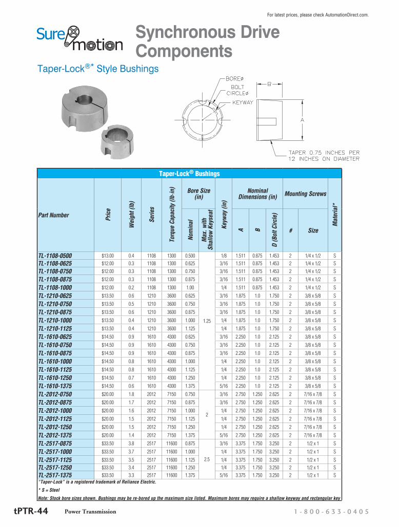
Taper-Lock®* Style Bushings
Taper-Lock® Bushings
Part Number Pric
e
Wei
ght (
lb)
Serie
s
Torq
ue C
apac
ity (l
b·in
) Bore Size (in)
Keyw
ay (i
n)
Nominal Dimensions (in) Mounting Screws
Mat
eria
l*
Nom
inal
Max
. with
Sh
allo
w K
eyse
at
A B
D (B
olt C
ircle
)
# Size
TL-1108-0500 $13.00 0.4 1108 1300 0.500
1.25
1/8 1.511 0.875 1.453 2 1/4 x 1/2 S
TL-1108-0625 $12.00 0.3 1108 1300 0.625 3/16 1.511 0.875 1.453 2 1/4 x 1/2 S
TL-1108-0750 $12.00 0.3 1108 1300 0.750 3/16 1.511 0.875 1.453 2 1/4 x 1/2 S
TL-1108-0875 $12.00 0.3 1108 1300 0.875 3/16 1.511 0.875 1.453 2 1/4 x 1/2 S
TL-1108-1000 $12.00 0.2 1108 1300 1.00 1/4 1.511 0.875 1.453 2 1/4 x 1/2 S
TL-1210-0625 $13.50 0.6 1210 3600 0.625 3/16 1.875 1.0 1.750 2 3/8 x 5/8 S
TL-1210-0750 $13.50 0.5 1210 3600 0.750 3/16 1.875 1.0 1.750 2 3/8 x 5/8 S
TL-1210-0875 $13.50 0.6 1210 3600 0.875 3/16 1.875 1.0 1.750 2 3/8 x 5/8 S
TL-1210-1000 $13.50 0.4 1210 3600 1.000 1/4 1.875 1.0 1.750 2 3/8 x 5/8 S
TL-1210-1125 $13.50 0.4 1210 3600 1.125 1/4 1.875 1.0 1.750 2 3/8 x 5/8 S
TL-1610-0625 $14.50 0.9 1610 4300 0.625 3/16 2.250 1.0 2.125 2 3/8 x 5/8 S
TL-1610-0750 $14.50 0.9 1610 4300 0.750 3/16 2.250 1.0 2.125 2 3/8 x 5/8 S
TL-1610-0875 $14.50 0.9 1610 4300 0.875 3/16 2.250 1.0 2.125 2 3/8 x 5/8 S
TL-1610-1000 $14.50 0.8 1610 4300 1.000 1/4 2.250 1.0 2.125 2 3/8 x 5/8 S
TL-1610-1125 $14.50 0.8 1610 4300 1.125 1/4 2.250 1.0 2.125 2 3/8 x 5/8 S
TL-1610-1250 $14.50 0.7 1610 4300 1.250 1/4 2.250 1.0 2.125 2 3/8 x 5/8 S
TL-1610-1375 $14.50 0.6 1610 4300 1.375 5/16 2.250 1.0 2.125 2 3/8 x 5/8 S
TL-2012-0750 $20.00 1.8 2012 7150 0.750
2
3/16 2.750 1.250 2.625 2 7/16 x 7/8 S
TL-2012-0875 $20.00 1.7 2012 7150 0.875 3/16 2.750 1.250 2.625 2 7/16 x 7/8 S
TL-2012-1000 $20.00 1.6 2012 7150 1.000 1/4 2.750 1.250 2.625 2 7/16 x 7/8 S
TL-2012-1125 $20.00 1.5 2012 7150 1.125 1/4 2.750 1.250 2.625 2 7/16 x 7/8 S
TL-2012-1250 $20.00 1.5 2012 7150 1.250 1/4 2.750 1.250 2.625 2 7/16 x 7/8 S
TL-2012-1375 $20.00 1.4 2012 7150 1.375 5/16 2.750 1.250 2.625 2 7/16 x 7/8 S
TL-2517-0875 $33.50 3.8 2517 11600 0.875
2.5
3/16 3.375 1.750 3.250 2 1/2 x 1 S
TL-2517-1000 $33.50 3.7 2517 11600 1.000 1/4 3.375 1.750 3.250 2 1/2 x 1 S
TL-2517-1125 $33.50 3.5 2517 11600 1.125 1/4 3.375 1.750 3.250 2 1/2 x 1 S
TL-2517-1250 $33.50 3.4 2517 11600 1.250 1/4 3.375 1.750 3.250 2 1/2 x 1 S
TL-2517-1375 $33.50 3.3 2517 11600 1.375 5/16 3.375 1.750 3.250 2 1/2 x 1 S“Taper-Lock” is a registered trademark of Reliance Electric.
* S = Steel
Note: Stock bore sizes shown. Bushings may be re-bored up the maximum size listed. Maximum bores may require a shallow keyway and rectangular key
Synchronous Drive Components
1 - 8 0 0 - 6 3 3 - 0 4 0 5Power TransmissiontPTR-44
For latest prices, please check AutomationDirect.com.

QD®* Style Bushings
QD® Bushings
Part Number Pric
e
Wei
ght (
lb)
Serie
s
Torq
ue C
apac
ity (l
b·in
)
Bore Size (in)
Keyw
ay (i
n)
Dimensions (in)
Bolt
Circ
le (i
n) Cap Screws
Mat
eria
l*
Nom
inal
Max
. with
Sh
allo
w
Keys
eat
A B D # Size
QD-JA-0500 $11.00 0.5
JA
1750 0.500 1-1/4 1/8 1.375 2.0 1.0 1.6563 3 #10 x 1 S
QD-JA-0625 $10.50 0.5 1750 0.625 1-1/4 3/16 1.375 2.0 1.0 1.6563 3 #10 x 1 S
QD-JA-0750 $10.50 0.4 1750 0.750 1-1/4 3/16 1.375 2.0 1.0 1.6563 3 #10 x 1 S
QD-JA-0875 $10.50 0.4 1750 0.875 1-1/4 3/16 1.375 2.0 1.0 1.6563 3 #10 x 1 S
QD-SH-0500 $14.50 1.3
SH
3500 0.500 1-5/8 1/8 1.871 2.6875 1.25 2.25 3 1/4 x 1-3/8 S
QD-SH-0625 $14.50 1.2 3500 0.625 1-5/8 3/16 1.871 2.6875 1.25 2.25 3 1/4 x 1-3/8 S
QD-SH-0750 $14.50 1.2 3500 0.750 1-5/8 3/16 1.871 2.6875 1.25 2.25 3 1/4 x 1-3/8 S
QD-SH-0875 $14.50 1.2 3500 0.875 1-5/8 3/16 1.871 2.6875 1.25 2.25 3 1/4 x 1-3/8 S
QD-SH-1000 $14.50 1.1 3500 1.000 1-5/8 1/4 1.871 2.6875 1.25 2.25 3 1/4 x 1-3/8 S
QD-SDS-0625 $18.50 1.8
SDS
5000 0.625 1-15/16 3/16 2.1875 3.1875 1.3125 2.6875 3 1/4 x 1-3/8 S
QD-SDS-0750 $18.50 1.8 5000 0.750 1-15/16 3/16 2.1875 3.1875 1.3125 2.6875 3 1/4 x 1-3/8 S
QD-SDS-0875 $18.50 1.8 5000 0.875 1-15/16 3/16 2.1875 3.1875 1.3125 2.6875 3 1/4 x 1-3/8 S
QD-SDS-1000 $18.50 1.6 5000 1.000 1-15/16 1/4 2.1875 3.1875 1.3125 2.6875 3 1/4 x 1-3/8 S
QD-SDS-1125 $18.50 1.5 5000 1.125 1-15/16 1/4 2.1875 3.1875 1.3125 2.6875 3 1/4 x 1-3/8 S
QD-SD-0750 $21.00 2.2
SD
5000 0.750 1-15/16 3/16 2.1875 3.1875 1.8125 2.6875 3 1/4 x 1-7/8 S
QD-SD-0875 $21.00 2.1 5000 0.875 1-15/16 3/16 2.1875 3.1875 1.8125 2.6875 3 1/4 x 1-7/8 S
QD-SD-1000 $21.00 2.0 5000 1.000 1-15/16 1/4 2.1875 3.1875 1.8125 2.6875 3 1/4 x 1-7/8 S
QD-SD-1125 $21.00 1.9 5000 1.125 1-15/16 1/4 2.1875 3.1875 1.8125 2.6875 3 1/4 x 1-7/8 S
QD-SD-1250 $21.00 1.8 5000 1.250 1-15/16 1/4 2.1875 3.1875 1.8125 2.6875 3 1/4 x 1-7/8 S“QD” is a registered trademark of Emerson Electric.
* S = Steel
Note: Stock bore sizes shown. Bushings may be re-bored up the maximum size listed. Maximum bores may require a shallow keyway and rectangular key.
Synchronous Drive Components
Power Transmissionw w w . a u t o m a t i o n d i r e c t . c o m / p o w e r - t r a n s m i s s i o n tPTR-45
For latest prices, please check AutomationDirect.com.

Synchronous Drive Timing Belts Neoprene with Fiberglass Reinforcement
Synchronous Drive Belts (MXL)
SureMotion timing belts are an excellent choice for many industrial applications. Belts are neoprene with fiberglass rein-forcement. Neoprene belts have excellent resilience and are flame resistant.
MXL Pitch
Neoprene with Fiberglass Reinforcement Timing Belts
Part Number Price Per 3pc Pkg
Wei
ght (
lb)
# Te
eth
Pitc
h De
sign
atio
n
Pitc
h (in
)
Circ
umfe
renc
e (in
)
Wid
th (i
n)Part Number Price Per
3pc Pkg
Wei
ght (
lb)
# Te
eth
Pitc
h De
sign
atio
n
Pitc
h (in
)
Circ
umfe
renc
e (in
)
Wid
th (i
n)
36MXL025NG $6.75 0.1 36 MXL 0.08 2.88 0.25 85MXL025NG $7.25 0.1 85 MXL 0.08 6.80 0.2540MXL025NG $6.75 0.1 40 MXL 0.08 3.20 0.25 87MXL025NG $7.25 0.1 87 MXL 0.08 6.96 0.25
42MXL025NG $6.75 0.1 42 MXL 0.08 3.36 0.25 88MXL025NG $7.50 0.1 88 MXL 0.08 7.04 0.25
44MXL025NG $6.75 0.1 44 MXL 0.08 3.52 0.25 90MXL025NG $7.50 0.1 90 MXL 0.08 7.20 0.25
45MXL025NG $6.75 0.1 45 MXL 0.08 3.60 0.25 91MXL025NG $7.50 0.1 91 MXL 0.08 7.28 0.25
47MXL025NG $6.75 0.1 47 MXL 0.08 3.76 0.25 95MXL025NG $7.50 0.1 95 MXL 0.08 7.60 0.25
48MXL025NG $6.75 0.1 48 MXL 0.08 3.84 0.25 98MXL025NG $7.50 0.1 98 MXL 0.08 7.84 0.25
50MXL025NG $6.75 0.1 50 MXL 0.08 4.00 0.25 100MXL025NG $7.50 0.1 100 MXL 0.08 8.00 0.25
52MXL025NG $6.75 0.1 52 MXL 0.08 4.16 0.25 101MXL025NG $7.50 0.1 101 MXL 0.08 8.08 0.25
53MXL025NG $6.75 0.1 53 MXL 0.08 4.24 0.25 104MXL025NG $7.50 0.1 104 MXL 0.08 8.32 0.25
54MXL025NG $6.75 0.1 54 MXL 0.08 4.32 0.25 106MXL025NG $7.50 0.1 106 MXL 0.08 8.48 0.25
55MXL025NG $6.75 0.1 55 MXL 0.08 4.40 0.25 112MXL025NG $7.50 0.1 112 MXL 0.08 8.96 0.25
56MXL025NG $6.75 0.1 56 MXL 0.08 4.48 0.25 115MXL025NG $7.75 0.1 115 MXL 0.08 9.20 0.25
57MXL025NG $6.75 0.1 57 MXL 0.08 4.56 0.25 120MXL025NG $7.75 0.1 120 MXL 0.08 9.60 0.25
58MXL025NG $6.75 0.1 58 MXL 0.08 4.64 0.25 122MXL025NG $7.75 0.1 122 MXL 0.08 9.76 0.25
59MXL025NG $6.75 0.1 59 MXL 0.08 4.72 0.25 124MXL025NG $7.75 0.1 124 MXL 0.08 9.92 0.25
60MXL025NG $6.75 0.1 60 MXL 0.08 4.80 0.25 130MXL025NG $8.00 0.1 130 MXL 0.08 10.40 0.25
61MXL025NG $6.75 0.1 61 MXL 0.08 4.88 0.25 132MXL025NG $8.00 0.1 132 MXL 0.08 10.56 0.25
62MXL025NG $6.75 0.1 62 MXL 0.08 4.96 0.25 134MXL025NG $8.00 0.1 134 MXL 0.08 10.72 0.25
63MXL025NG $7.00 0.1 63 MXL 0.08 5.04 0.25 136MXL025NG $9.00 0.1 136 MXL 0.08 10.88 0.25
64MXL025NG $7.00 0.1 64 MXL 0.08 5.12 0.25 140MXL025NG $8.25 0.1 140 MXL 0.08 11.20 0.25
65MXL025NG $7.00 0.1 65 MXL 0.08 5.20 0.25 146MXL025NG $8.25 0.1 146 MXL 0.08 11.68 0.25
67MXL025NG $7.00 0.1 67 MXL 0.08 5.36 0.25 150MXL025NG $8.25 0.1 150 MXL 0.08 12.00 0.25
68MXL025NG $7.00 0.1 68 MXL 0.08 5.44 0.25 156MXL025NG $10.50 0.1 156 MXL 0.08 12.48 0.25
69MXL025NG $7.00 0.1 69 MXL 0.08 5.52 0.25 160MXL025NG $8.25 0.1 160 MXL 0.08 12.80 0.25
70MXL025NG $7.00 0.1 70 MXL 0.08 5.60 0.25 166MXL025NG $8.50 0.1 166 MXL 0.08 13.28 0.25
72MXL025NG $7.00 0.1 72 MXL 0.08 5.76 0.25 170MXL025NG $8.50 0.1 170 MXL 0.08 13.60 0.25
74MXL025NG $7.25 0.1 74 MXL 0.08 5.92 0.25 177MXL025NG $10.50 0.1 177 MXL 0.08 14.16 0.25
75MXL025NG $7.25 0.1 75 MXL 0.08 6.00 0.25 180MXL025NG $9.00 0.1 180 MXL 0.08 14.40 0.25
76MXL025NG $7.25 0.1 76 MXL 0.08 6.08 0.25 184MXL025NG $9.00 0.1 184 MXL 0.08 14.72 0.25
80MXL025NG $7.25 0.1 80 MXL 0.08 6.40 0.25 192MXL025NG $9.00 0.1 192 MXL 0.08 15.36 0.25
81MXL025NG $7.25 0.1 81 MXL 0.08 6.48 0.25 195MXL025NG $9.00 0.1 195 MXL 0.08 15.60 0.25
82MXL025NG $7.25 0.1 82 MXL 0.08 6.56 0.25 200MXL025NG $9.25 0.1 200 MXL 0.08 16.00 0.25
84MXL025NG $7.25 0.1 84 MXL 0.08 6.72 0.25
1 - 8 0 0 - 6 3 3 - 0 4 0 5Power TransmissiontPTR-46
For latest prices, please check AutomationDirect.com.

Synchronous Drive Timing Belts Neoprene with Fiberglass Reinforcement
Table continued from previous page.
Neoprene with Fiberglass Reinforcement Timing Belts
Part Number Price Per 3pc Pkg
Wei
ght (
lb)
# Te
eth
Pitc
h De
sign
atio
n
Pitc
h (in
)
Circ
umfe
renc
e (in
)
Wid
th (i
n)
Part Number Price Per 3pc Pkg
Wei
ght (
lb)
# Te
eth
Pitc
h De
sign
atio
n
Pitc
h (in
)
Circ
umfe
renc
e (in
)
Wid
th (i
n)
208MXL025NG $9.25 0.1 208 MXL 0.08 16.64 0.25 310MXL025NG $11.50 0.1 310 MXL 0.08 24.80 0.25
212MXL025NG $9.25 0.1 212 MXL 0.08 16.96 0.25 320MXL025NG $11.50 0.1 320 MXL 0.08 25.60 0.25
220MXL025NG $9.75 0.1 220 MXL 0.08 17.60 0.25 330MXL025NG $11.50 0.1 330 MXL 0.08 26.40 0.25
224MXL025NG $9.75 0.1 224 MXL 0.08 17.92 0.25 343MXL025NG $12.00 0.1 343 MXL 0.08 27.44 0.25
230MXL025NG $10.00 0.1 230 MXL 0.08 18.40 0.25 355MXL025NG $12.00 0.1 355 MXL 0.08 28.40 0.25
236MXL025NG $12.00 0.1 236 MXL 0.08 18.88 0.25 372MXL025NG $12.50 0.1 372 MXL 0.08 29.76 0.25
240MXL025NG $10.50 0.1 240 MXL 0.08 19.20 0.25 390MXL025NG $13.00 0.1 390 MXL 0.08 31.20 0.25
250MXL025NG $10.50 0.1 250 MXL 0.08 20.00 0.25 400MXL025NG $13.00 0.1 400 MXL 0.08 32.00 0.25
260MXL025NG $10.50 0.1 260 MXL 0.08 20.80 0.25 440MXL025NG $13.50 0.1 440 MXL 0.08 35.20 0.25
280MXL025NG $11.00 0.1 280 MXL 0.08 22.40 0.25 480MXL025NG $14.00 0.1 480 MXL 0.08 38.40 0.25
300MXL025NG $11.50 0.1 300 MXL 0.08 24.00 0.25 500MXL025NG $14.50 0.1 500 MXL 0.08 40.00 0.25
Synchronous Drive Belts (MXL)
Power Transmissionw w w . a u t o m a t i o n d i r e c t . c o m / p o w e r - t r a n s m i s s i o n tPTR-47
For latest prices, please check AutomationDirect.com.
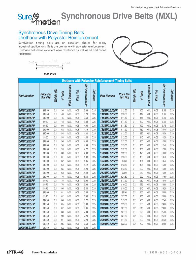
Synchronous Drive Timing Belts Urethane with Polyester Reinforcement
Urethane with Polyester Reinforcement Timing Belts
Part Number Price Per 3pc Pkg
Wei
ght (
lb)
# Te
eth
Pitc
h De
sign
atio
n
Pitc
h (in
)
Circ
umfe
renc
e (in
)
Wid
th (i
n)Part Number Price Per
3pc Pkg
Wei
ght (
lb)
# Te
eth
Pitc
h De
sign
atio
n
Pitc
h (in
)
Circ
umfe
renc
e (in
)
Wid
th (i
n)
36MXL025PP $12.50 0.1 36 MXL 0.08 2.88 0.25 106MXL025PP $12.50 0.1 106 MXL 0.08 8.48 0.2540MXL025PP $12.50 0.1 40 MXL 0.08 3.20 0.25 112MXL025PP $13.00 0.1 112 MXL 0.08 8.96 0.25
45MXL025PP $12.00 0.1 45 MXL 0.08 3.60 0.25 115MXL025PP $11.50 0.1 115 MXL 0.08 9.20 0.25
48MXL025PP $9.50 0.1 48 MXL 0.08 3.84 0.25 120MXL025PP $11.50 0.1 120 MXL 0.08 9.60 0.25
50MXL025PP $9.50 0.1 50 MXL 0.08 4.00 0.25 122MXL025PP $11.50 0.1 122 MXL 0.08 9.76 0.25
52MXL025PP $12.00 0.1 52 MXL 0.08 4.16 0.25 130MXL025PP $11.50 0.1 130 MXL 0.08 10.40 0.25
54MXL025PP $10.00 0.1 54 MXL 0.08 4.32 0.25 132MXL025PP $12.00 0.1 132 MXL 0.08 10.56 0.25
55MXL025PP $9.50 0.1 55 MXL 0.08 4.40 0.25 140MXL025PP $12.00 0.1 140 MXL 0.08 11.20 0.25
56MXL025PP $12.00 0.1 56 MXL 0.08 4.48 0.25 150MXL025PP $12.00 0.1 150 MXL 0.08 12.00 0.25
58MXL025PP $12.00 0.1 58 MXL 0.08 4.64 0.25 156MXL025PP $15.00 0.1 156 MXL 0.08 12.48 0.25
59MXL025PP $12.00 0.1 59 MXL 0.08 4.72 0.25 160MXL025PP $12.50 0.1 160 MXL 0.08 12.80 0.25
60MXL025PP $10.00 0.1 60 MXL 0.08 4.80 0.25 170MXL025PP $12.50 0.1 170 MXL 0.08 13.60 0.25
61MXL025PP $12.00 0.1 61 MXL 0.08 4.88 0.25 180MXL025PP $13.00 0.1 180 MXL 0.08 14.40 0.25
62MXL025PP $12.00 0.1 62 MXL 0.08 4.96 0.25 184MXL025PP $9.50 0.1 184 MXL 0.08 14.72 0.25
64MXL025PP $10.00 0.1 64 MXL 0.08 5.12 0.25 195MXL025PP $13.50 0.1 195 MXL 0.08 15.60 0.25
65MXL025PP $10.00 0.1 65 MXL 0.08 5.20 0.25 200MXL025PP $13.50 0.1 200 MXL 0.08 16.00 0.25
68MXL025PP $12.00 0.1 68 MXL 0.08 5.44 0.25 212MXL025PP $9.50 0.1 212 MXL 0.08 16.96 0.25
70MXL025PP $10.00 0.1 70 MXL 0.08 5.60 0.25 220MXL025PP $24.50 0.1 220 MXL 0.08 17.60 0.25
75MXL025PP $9.75 0.1 75 MXL 0.08 6.00 0.25 230MXL025PP $13.50 0.1 230 MXL 0.08 18.40 0.25
76MXL025PP $9.75 0.1 76 MXL 0.08 6.08 0.25 236MXL025PP $19.00 0.2 236 MXL 0.08 18.88 0.25
80MXL025PP $9.75 0.1 80 MXL 0.08 6.40 0.25 240MXL025PP $19.00 0.1 240 MXL 0.08 19.20 0.25
81MXL025PP $14.00 0.1 81 MXL 0.08 6.48 0.25 250MXL025PP $9.50 0.2 250 MXL 0.08 20.00 0.25
82MXL025PP $9.75 0.1 82 MXL 0.08 6.56 0.25 260MXL025PP $27.50 0.1 260 MXL 0.08 20.80 0.25
84MXL025PP $12.50 0.1 84 MXL 0.08 6.72 0.25 280MXL025PP $19.00 0.2 280 MXL 0.08 22.40 0.25
85MXL025PP $10.50 0.1 85 MXL 0.08 6.80 0.25 300MXL025PP $19.50 0.1 300 MXL 0.08 24.00 0.25
87MXL025PP $10.50 0.1 87 MXL 0.08 6.96 0.25 310MXL025PP $27.50 0.2 310 MXL 0.08 24.80 0.25
88MXL025PP $10.50 0.1 88 MXL 0.08 7.04 0.25 320MXL025PP $27.50 0.1 320 MXL 0.08 25.60 0.25
90MXL025PP $10.50 0.1 90 MXL 0.08 7.20 0.25 330MXL025PP $27.50 0.2 330 MXL 0.08 26.40 0.25
91MXL025PP $10.50 0.1 91 MXL 0.08 7.28 0.25 390MXL025PP $14.50 0.1 390 MXL 0.08 31.20 0.25
95MXL025PP $10.50 0.1 95 MXL 0.08 7.60 0.25 400MXL025PP $23.00 0.2 400 MXL 0.08 32.00 0.25
100MXL025PP $10.50 0.1 100 MXL 0.08 8.00 0.25
SureMotion timing belts are an excellent choice for many industrial applications. Belts are urethane with polyester reinforcement. Urethane belts have excellent wear resistance as well as oil and ozone resistance.
MXL Pitch
Synchronous Drive Belts (MXL)
1 - 8 0 0 - 6 3 3 - 0 4 0 5Power TransmissiontPTR-48
For latest prices, please check AutomationDirect.com.
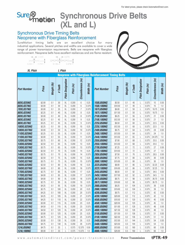
Synchronous Drive Timing Belts Neoprene with Fiberglass Reinforcement
Neoprene with Fiberglass Reinforcement Timing Belts
Part Number Pric
e
Wei
ght (
lb)
# Te
eth
Pitc
h De
sign
atio
n
Pitc
h (in
)
Circ
umfe
renc
e (in
)
Wid
th (i
n)Part Number Pr
ice
Wei
ght (
lb)
# Te
eth
Pitc
h De
sign
atio
n
Pitc
h (in
)
Circ
umfe
renc
e (in
)
Wid
th (i
n)
60XL025NG $2.00 0.1 30 XL 0.200 6 0.25 150L050NG $5.50 0.1 40 L 0.375 15 0.5060XL037NG $3.00 0.1 30 XL 0.200 6 0.375 150L100NG $10.50 0.1 40 L 0.375 15 1.070XL037NG $3.00 0.1 35 XL 0.200 7 0.375 187L050NG $6.00 0.1 50 L 0.375 18.75 0.5080XL025NG $2.25 0.1 40 XL 0.200 8 0.25 187L100NG $11.50 0.1 50 L 0.375 18.75 1.0
80XL037NG $3.00 0.1 40 XL 0.200 8 0.375 210L050NG $6.25 0.1 56 L 0.375 21 0.50
90XL025NG $2.25 0.1 45 XL 0.200 9 0.25 210L100NG $12.50 0.1 56 L 0.375 21 1.0
90XL037NG $3.25 0.1 45 XL 0.200 9 0.375 225L050NG $6.50 0.1 60 L 0.375 22.5 0.50
100XL025NG $2.25 0.1 50 XL 0.200 10 0.25 225L100NG $12.50 0.1 60 L 0.375 22.5 1.0
100XL037NG $3.00 0.1 50 XL 0.200 10 0.375 240L050NG $6.75 0.1 64 L 0.375 24 0.50
110XL025NG $2.25 0.1 55 XL 0.200 11 0.25 240L100NG $13.50 0.1 64 L 0.375 24 1.0
110XL037NG $3.00 0.1 55 XL 0.200 11 0.375 244L100NG $13.50 0.1 65 L 0.375 24.375 1.0
120XL037NG $3.75 0.1 60 XL 0.200 12 0.375 255L050NG $7.00 0.1 68 L 0.375 25.5 0.50
130XL025NG $2.50 0.1 65 XL 0.200 13 0.25 255L100NG $13.50 0.1 68 L 0.375 25.5 1.0
130XL037NG $3.75 0.1 65 XL 0.200 13 0.375 270L050NG $7.25 0.1 72 L 0.375 27 0.50
140XL025NG $2.50 0.1 70 XL 0.200 14 0.25 270L100NG $14.50 0.1 72 L 0.375 27 1.0
140XL037NG $3.75 0.1 70 XL 0.200 14 0.375 285L050NG $7.50 0.1 76 L 0.375 28.5 0.50
150XL025NG $2.50 0.1 75 XL 0.200 15 0.25 300L050NG $7.75 0.1 80 L 0.375 30 0.50
150XL037NG $3.75 0.1 75 XL 0.200 15 0.375 300L100NG $15.00 0.1 80 L 0.375 30 1.0
160XL025NG $2.50 0.1 80 XL 0.200 16 0.25 322L050NG $8.00 0.1 86 L 0.375 32.25 0.50
160XL037NG $4.00 0.1 80 XL 0.200 16 0.375 322L100NG $16.00 0.2 86 L 0.375 32.25 1.0
170XL025NG $2.75 0.1 85 XL 0.200 17 0.25 345L050NG $8.50 0.1 92 L 0.375 34.5 0.50
170XL037NG $4.00 0.1 85 XL 0.200 17 0.375 345L100NG $17.00 0.2 92 L 0.375 34.5 1.0
180XL037NG $4.00 0.1 90 XL 0.200 18 0.375 367L050NG $8.75 0.1 98 L 0.375 36.75 0.50
190XL025NG $2.75 0.1 95 XL 0.200 19 0.25 367L100NG $18.00 0.2 98 L 0.375 36.75 1.0
190XL037NG $4.25 0.1 95 XL 0.200 19 0.375 390L050NG $9.25 0.1 104 L 0.375 39 0.50
200XL025NG $2.75 0.1 100 XL 0.200 20 0.25 390L100NG $19.00 0.2 104 L 0.375 39 1.0
200XL037NG $4.25 0.1 100 XL 0.200 20 0.375 420L050NG $9.75 0.1 112 L 0.375 42 0.50
210XL037NG $4.25 0.1 105 XL 0.200 21 0.375 420L100NG $20.00 0.2 112 L 0.375 42 1.0
220XL037NG $4.25 0.1 110 XL 0.200 22 0.375 450L050NG $10.50 0.1 120 L 0.375 45 0.50
230XL025NG $3.00 0.1 115 XL 0.200 23 0.25 450L100NG $20.50 0.2 120 L 0.375 45 1.0
230XL037NG $4.50 0.1 115 XL 0.200 23 0.375 480L050NG $11.00 0.1 128 L 0.375 48 0.50
240XL037NG $4.50 0.1 120 XL 0.200 24 0.375 480L100NG $21.50 0.2 128 L 0.375 48 1.0
250XL025NG $3.00 0.1 125 XL 0.200 25 0.25 510L050NG $11.50 0.1 136 L 0.375 51 0.50
250XL037NG $4.75 0.1 125 XL 0.200 25 0.375 510L100NG $22.50 0.2 136 L 0.375 51 1.0
260XL025NG $3.00 0.1 130 XL 0.200 26 0.25 540L050NG $12.00 0.1 144 L 0.375 54 0.50
260XL037NG $4.75 0.1 130 XL 0.200 26 0.375 540L100NG $23.50 0.3 144 L 0.375 54 1.0
124L050NG $4.75 0.1 33 L 0.375 12.375 0.50 600L050NG $13.00 0.2 160 L 0.375 60 0.50
124L100NG $9.00 0.1 33 L 0.375 13.375 1.0 600L100NG $26.00 0.3 160 L 0.375 60 1.0
SureMotion timing belts are an excellent choice for many industrial applications. Several pitches and widths are available to cover a wide range of power transmission requirements. Belts are neoprene with fiberglass reinforcement. Neoprene belts have excellent resiliences and are flame resistant.
XL Pitch L Pitch
Synchronous Drive Belts (XL and L)
Power Transmissionw w w . a u t o m a t i o n d i r e c t . c o m / p o w e r - t r a n s m i s s i o n tPTR-49
For latest prices, please check AutomationDirect.com.