The Power of Ethernet
1
The Power of Ethernet
An Analysis of Power Consumption Within Ethernet Circuits
By Mike Jones
Senior FAE, Micrel Inc.
Micrel, Inc. • 2180 Fortune Drive • San Jose, CA 95131 • USA • tel + 1 (408) 944-0800 • fax 1 (408) 474-1000 • http://www.micrel.com

The Power of Ethernet
2
Calculating the power consumption of an Ethernet circuit is not a straight forward
procedure. In this paper we look at where the current is consumed and how to design for the
lowest power consumption, both in operation and standby.
Increasingl, power consumption in electronic applications has become both critical and
challenging as world wide legislation forces manufacturers to improve energy efficiencies. Not
only is the power consumed when devices are in operation key but also during ‘standby’ periods.
As devices become faster and denser, power consumption continues to rise. Studies have shown
that standby power can account for up to 25 percent of the electricity consumed in homes. To help
save energy, the International Energy Agency (IEA) has proposed a reduction in standby power in
all applications to a maximum of 1 Watt by 2010. This initiative is appropriately called the ‘One
Watt Initiative’.
Ethernet is a dominating technology in today’s digital home, but the IEEE never considered power
consumption as a significant factor in the original specifications. To successfully deliver low
power Ethernet designs, it is important to first understand where the power is dissipated. In any
Ethernet device, the major power dissipation is from the PHY transceiver. Power is consumed
both internally to the PHY and externally in the transformer, as shown in Figure 1 below.
TX+
TX- To
RJ45
Ethernet
PHY
RX+
RX- To
RJ45
Iphy Itrans
Figure 1. Power Dissipation in an Ethernet PHY Circuit.

The Power of Ethernet
3
Ethernet datasheets commonly publish the device only current consumption. In which case, to
calculate the total circuit current consumption the designer must add typically around 40mA per
100Base-TX or 70mA per 10Base-T PHY for dissipation in the transformers. Hence, a lower
device only consumption at 10Base-T will rarely equate to lower total circuit current consumption,
relative to 100Base-TX mode.
To investigate further how to reduce power consumption, consider the following two modes;
Operation and Standby.
Ethernet Power Consumption During "ormal Operation
So, what is the definition of normal operation for an Ethernet network? Is it 100 percent
utilisation, 50 percent utilisation, or 10 percent utilisation? When analyzing a network one can
discover long quiet periods followed by relatively short bursts of traffic, as shown in Figure 2
below.
During these quiet periods, one may expect the Ethernet power consumption to significantly drop,
however, this turns out to not necessarily be the case.
0%
20%
40%
60%
80%
100%
0 1000 2000 3000 4000 5000 6000 7000
Time (s)
Utilization
Figure 2. Example of Typical Ethernet "etwork Utilization.
Source: Portland State University

The Power of Ethernet
4
Idle Period
1000Base-TX and 100Base-TX are both designed so that the link partners are continually
‘synchronized’ to each other. To enable this, when no traffic is being transmitted the PHY will
automatically send out IDLE symbols (11111 5B code), as shown in Figure 3 below.
As a consequence, during any quiet period the PHY transmitter is still operating in a manner
similar to full traffic and will therefore consume a similar amount of power.
It is strongly advisable with multi-port Ethernet devices, to disable any unused port (PHY). As has
been seen, just by connecting to a link partner, 40mA current (externally in the transformer) is
consumed even with no traffic present. The port can usually be disabled via the internal register
map (Register 0h bit 11 of the IEEE Defined PHY Registers) and will typically save a further 15-
20mA of device current.
10Base-T operation, however, differs during quiet periods. When no traffic is present, the PHY
transmitter does not transmit out any IDLE symbols. Instead, it sends out a single link pulse
approximately every 16ms, as shown in Figure 4 below.
Figure 3. 100Base-TX Idle Pattern.

The Power of Ethernet
5
The link pulses are designed simply to keep the link alive. The power consumption of the PHY
itself during a quiet period in 10Base-T operation will not reduce significantly, but the current
consumed externally in the transformer will reduce to negligible. This will save around 70mA per
PHY compared to full traffic.
Cable Length, Driver Strength
A major obstacle in the original IEEE 802.3 specification, with respect to energy saving, is the
definition of the PHY output waveform mask. For Ethernet conformance, the PHY transmitter
must adhere to fitting within the defined limits of the mask shown in Figure 5.
Figure 4. 10Base-T Link Pulse.
Figure 5. 100Base-TX IEEE802.3 Output Eye Diagram.
The Power of Ethernet
6
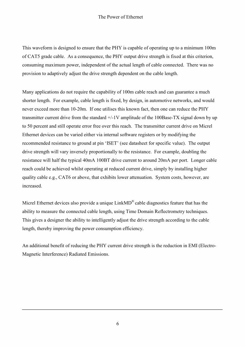
This waveform is designed to ensure that the PHY is capable of operating up to a minimum 100m
of CAT5 grade cable. As a consequence, the PHY output drive strength is fixed at this criterion,
consuming maximum power, independent of the actual length of cable connected. There was no
provision to adaptively adjust the drive strength dependent on the cable length.
Many applications do not require the capability of 100m cable reach and can guarantee a much
shorter length. For example, cable length is fixed, by design, in automotive networks, and would
never exceed more than 10-20m. If one utilises this known fact, then one can reduce the PHY
transmitter current drive from the standard +/-1V amplitude of the 100Base-TX signal down by up
to 50 percent and still operate error free over this reach. The transmitter current drive on Micrel
Ethernet devices can be varied either via internal software registers or by modifying the
recommended resistance to ground at pin ‘ISET’ (see datasheet for specific value). The output
drive strength will vary inversely proportionally to the resistance. For example, doubling the
resistance will half the typical 40mA 100BT drive current to around 20mA per port. Longer cable
reach could be achieved whilst operating at reduced current drive, simply by installing higher
quality cable e.g., CAT6 or above, that exhibits lower attenuation. System costs, however, are
increased.
Micrel Ethernet devices also provide a unique LinkMD® cable diagnostics feature that has the
ability to measure the connected cable length, using Time Domain Reflectrometry techniques.
This gives a designer the ability to intelligently adjust the drive strength according to the cable
length, thereby improving the power consumption efficiency.
An additional benefit of reducing the PHY current drive strength is the reduction in EMI (Electro-
Magnetic Interference) Radiated Emissions.
The Power of Ethernet
7
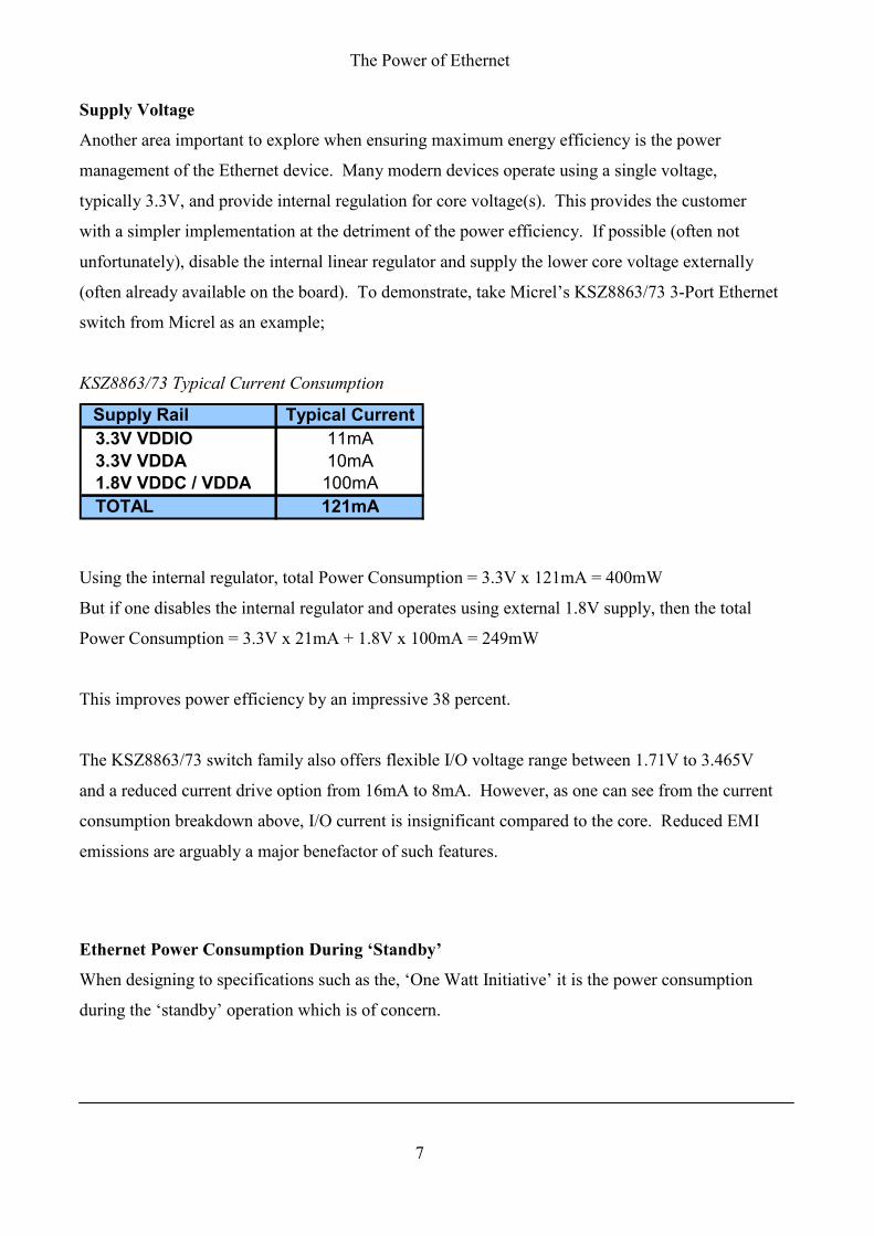
Supply Voltage
Another area important to explore when ensuring maximum energy efficiency is the power
management of the Ethernet device. Many modern devices operate using a single voltage,
typically 3.3V, and provide internal regulation for core voltage(s). This provides the customer
with a simpler implementation at the detriment of the power efficiency. If possible (often not
unfortunately), disable the internal linear regulator and supply the lower core voltage externally
(often already available on the board). To demonstrate, take Micrel’s KSZ8863/73 3-Port Ethernet
switch from Micrel as an example;
KSZ8863/73 Typical Current Consumption
Supply Rail Typical Current
3.3V VDDIO 11mA
3.3V VDDA 10mA
1.8V VDDC / VDDA 100mA
TOTAL 121mA
Using the internal regulator, total Power Consumption = 3.3V x 121mA = 400mW
But if one disables the internal regulator and operates using external 1.8V supply, then the total
Power Consumption = 3.3V x 21mA + 1.8V x 100mA = 249mW
This improves power efficiency by an impressive 38 percent.
The KSZ8863/73 switch family also offers flexible I/O voltage range between 1.71V to 3.465V
and a reduced current drive option from 16mA to 8mA. However, as one can see from the current
consumption breakdown above, I/O current is insignificant compared to the core. Reduced EMI
emissions are arguably a major benefactor of such features.
Ethernet Power Consumption During ‘Standby’
When designing to specifications such as the, ‘One Watt Initiative’ it is the power consumption
during the ‘standby’ operation which is of concern.

The Power of Ethernet
8
Power Down Mode
Typically, the Ethernet device power-down state is controlled via an internal register bit. When
enabled, the device is completely powered down except for the management interface. The latest
Ethernet PHY family, Micrel’s KSZ8031/51, reduces the current consumption further with the
ability to slow down the internal clock oscillator, during power-down mode. Current consumption
can be reduced from around 3.5mA to 1.5mA under these conditions. See also Soft Power Down
mode below.
Power Saving Mode – Energy Detect
Power saving mode is used to reduce the PHY power consumption automatically when the cable is
unplugged or link partner disabled. The receive circuit detects the presence or absence of a signal,
commonly known as ‘energy detect’ to enter or exit power saving mode.
The KSZ8863/73 switch family supports an enhanced Energy Detect Power Management for
lower power consumption. There are five modes of operation configured by register PMECR
(Power Management Event Control Register);
1. "ormal Operation Mode
2. Power Saving Mode
3. Energy Detect Mode
4. Soft Power Down Mode
Normal Power Saving Energy Detect Soft Power Down
Internal PLL Clock Enabled Enabled Disabled Disabled
Tx/Rx PHY Enabled Energy Detect + TX
enabled
Energy Detect only Disabled
Mac Enabled Enabled Disabled Disabled
Host Interface Enabled Enabled Disabled Enabled
Power Consumption 250mW 180mW 100mW 9.5mW
KSZ8863/73
Functional Blocks
Power Management Operation Modes
Table 1. Status of Internal Functional Blocks During Power Management Modes.
The Power of Ethernet
9
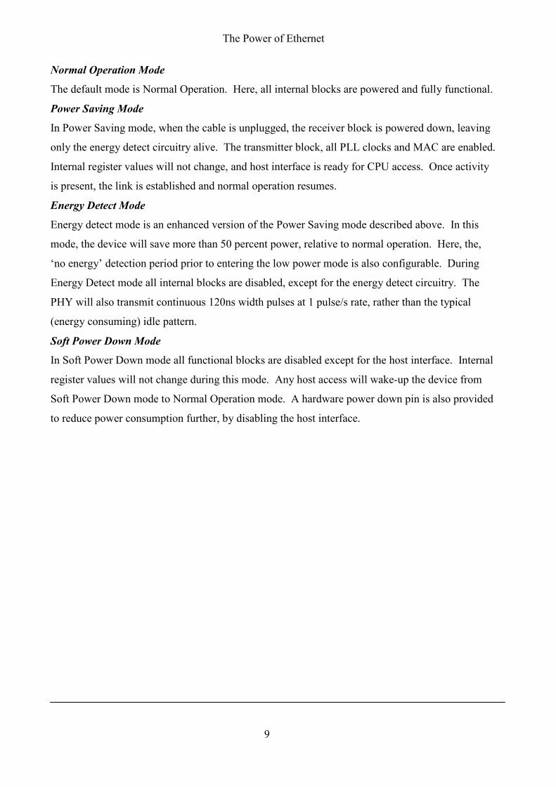
�ormal Operation Mode
The default mode is Normal Operation. Here, all internal blocks are powered and fully functional.
Power Saving Mode
In Power Saving mode, when the cable is unplugged, the receiver block is powered down, leaving
only the energy detect circuitry alive. The transmitter block, all PLL clocks and MAC are enabled.
Internal register values will not change, and host interface is ready for CPU access. Once activity
is present, the link is established and normal operation resumes.
Energy Detect Mode
Energy detect mode is an enhanced version of the Power Saving mode described above. In this
mode, the device will save more than 50 percent power, relative to normal operation. Here, the,
‘no energy’ detection period prior to entering the low power mode is also configurable. During
Energy Detect mode all internal blocks are disabled, except for the energy detect circuitry. The
PHY will also transmit continuous 120ns width pulses at 1 pulse/s rate, rather than the typical
(energy consuming) idle pattern.
Soft Power Down Mode
In Soft Power Down mode all functional blocks are disabled except for the host interface. Internal
register values will not change during this mode. Any host access will wake-up the device from
Soft Power Down mode to Normal Operation mode. A hardware power down pin is also provided
to reduce power consumption further, by disabling the host interface.
The Power of Ethernet
10
Figure 6. Power Management State Diagram.
Wake-on-LA"
Wake-on-LAN (WoL) is often spoken of as a solution to ‘wake up’ the system during a low power
idle state. However, the reality is that such this feature rarely achieves its goal.
A special wake up sequence is sent to the Ethernet device, which it will detect and assert an
interrupt signal used to notify the host to power up the rest of the system. Arguably, the reason
why WoL has never become popular is that the solution is not standards driven. There is also no
single common defined wake up sequenced, which hinders interoperability across vendors. AMD
did define the Magic Packet™ for WoL use, consisting of a sequence of 16 duplications of the
device MAC address, preceded by a synchronization stream, defined as 6 bytes of FFh. T his
sequence can be located anywhere within a standard Ethernet packet.
A second limitation when minimising standby power is found in the implementation of WoL
functionality in the MAC, not PHY layer. The PHY device is purely a transceiver and is
transparent to the received packet contents. It is often not appreciated that both the MAC and PHY
must operate in normal and not a low power mode prior to system wake up. As one has seen, even
with no traffic the idle state of a 100Base-TX PHY consumes full power. Furthermore, most
embedded applications, such as IP STB and VoIP phones, already embed the Ethernet MAC inside

The Power of Ethernet
11
the core processor, neglecting WoL support. Without hardware support, now the processor too
would have to be powered to detect WoL packets. Hence, today’s power saving initiative targets
are unachievable using WoL.
WoL is usually only featured on Ethernet MAC/PHY Controller devices, found in computer NIC
cards, which, to be fair, was its original and only intention. However, to benefit another WoL-
enabled network device, configured to wake up the computer when in a sleeping state, needs to be
present. How often is this the case in a home?

The Power of Ethernet
12
Energy Efficient Ethernet IEEE 802.3az
Power consumption inefficiency within Ethernet circuits has already been recognised by the IEEE.
The IEEE 802.3az task force, also known as Energy Efficient Ethernet, is targeted to reduce power
consumption during periods of low link utilization (idle time). As we have already seen in Figure
3, typical Ethernet traffic utilization of a link is extremely low, estimated to be sub-3 percent for
10/100Base-TX links and even lower for GigE1. To achieve this goal then changes are needed to
the hardware, however, they must be fully backwards compatible.
By reducing the power consumption during low link utilization periods one can drastically
improve on power efficiency. This technique, known as Low Power Idle (LPI), will disable parts
of the PHY transceiver that are not necessary, whilst still maintaining the link integrity. When
new frames arrive, the PHY is awoken and the returns to the normal active state. During LPI, a
periodic refresh symbol is sent out by the PHY to ensure that the receiver is synchronized. An
example of IEEE 802.3az Energy Efficient Ethernet operation is show in Figure 7.
Figure 7. Example of IEEE 802.3az Energy Efficient Ethernet.

The Power of Ethernet
13
As shown in Figure 7, when a frame arrives for transmission and the link is in the low power
mode, it has to wait until the link is awoken before transmission can begin. This does introduce an
additional latency Tw_PHY in the data path. Proposed wake up times for 100Base-TX and 1000-
BaseT are 30usec and 16.5usec, respectively.
Currently, only 100Base-TX (full duplex), 1000Base-T and 10G PHYs have been targeted. The
specification is likely to be finalised later on this year. Ethernet devices supporting IEEE 802.3az
are expected to be available on the market shortly after this.
Conclusion
When analysing power consumption within Ethernet circuitry it has been shown it to be far from
efficient. Ethernet consumes similar energy during both traffic and idle periods. When one further
analyses the make up of a typical Ethernet network, it is discovered that idle periods typically
account for more than 97 percent of the time. This finding makes it patently obvious where
improvements can be made. The IEEE have recognised this inefficiency and formed a task force
with the goal to reduce power consumption during periods of low utilization. This task force IEEE
802.3az is commonly known as Energy Efficient Energy. Energy Efficient Ethernet is destined to
succeed where previous attempts in the past to reduce idle period power have failed with Wake-on-
LAN.
To compliment Energy Efficient Ethernet solutions this paper has shown that with careful
consideration and understanding additional power savings can also be made both during normal
traffic and link down.
Micrel will continue to offer ‘Green’ Ethernet solutions with advanced power management, saving
energy and lowering EMI emissions.
For further details on Micrel Ethernet Solutions go to:
http://www.micrel.com/page.do?page=product-info/ether_over.jsp
1 Source: Ethernet Alliance/Portland State University study.

The Power of Ethernet
14
Note: LinkMD is a registered trademark of Micrel Inc. Magic Packet™ is a registered trademark of Advance Micro
Devices Inc.