PCoIP® Zero Client and HostAdministrator Guide
TER1206003
Issue 13
Teradici Corporation
#101-4621CanadaWay, Burnaby, BC V5G 4X8Canada
phone +1.604.451.5800 fax +1.604.451.5818
www.teradici.com
The information contained in this documentation represents the current view of Teradici Corporation as of the date ofpublication. Because Teradicimust respond to changingmarket conditions, it should not be interpreted to be a commitmenton the part of Teradici, and Teradici cannot guarantee the accuracy of any information presented after the date ofpublication.
This document is for informational purposes only. TERADICI MAKES NOWARRANTIES, EXPRESS, IMPLIED OR STATUTORY, ASTO THE INFORMATION IN THIS DOCUMENT.
Complying with all applicable copyright laws is the responsibility of the user. Without limiting the rights under copyright, nopart of this document may be reproduced, stored in or introduced into a retrieval system, or transmitted in any form or byany means (electronic, mechanical, photocopying, recording, or otherwise), or for any purpose, without the express writtenpermission of Teradici Corporation.
Teradicimay have patents, patent applications, trademarks, copyrights, or other intellectual property rights covering subjectmatter in this document. Except as expressly provided in any written license agreement from Teradici, the furnishing of thisdocument does not give you any license to these patents, trademarks, copyrights, or other intellectual property. Visithttp://www.teradici.com/about-teradici/pat.php for more information.
© 2000-2015 Teradici Corporation. All rights reserved.
Teradici, PC-over-IP, and PCoIP are trademarks of Teradici Corporation and may be registered in theUnited States and/orother countries. Any other trademarks or registered trademarksmentioned in this release are the intellectual property of theirrespective owners.
TER1206003 Issue 13 2
PCoIP® Zero Client and Host Administrator Guide

Contents
Table of Figures 12
Table of Tables 19
1 Welcome 25
1.1 Introduction 25
2 What's New 27
2.1 What's New in Firmware 4.7.2 27
2.1.1 Upgrade Instructions 27
2.2 What's New in This Interim Help Release 27
2.3 What's New in Firmware 4.8.0 28
2.4 What's New in Firmware 4.7.0 31
2.5 What's New in Firmware 4.6.0 33
2.6 What's New in Firmware 4.5.1 34
2.7 What's New in Firmware 4.5.0 35
2.8 What's New in Firmware 4.2.0 40
2.9 What's New in Firmware 4.1.2 43
2.10 What's New in Firmware 4.1.0 43
2.10.1 Workstation and VDI 43
2.10.2 VDI-specific 45
2.10.3 Workstation-specific 45
2.11 What's New in Firmware 4.0.3 45
2.12 What's New in Firmware 4.0.2 46
2.13 What's New in Firmware 4.0.0 47
2.14 What's New in Firmware 3.5.0 48
2.15 What's New in Firmware 3.4.1 49
2.16 What's New in Firmware 3.4.0 49
3 Zero Clients 50
3.1 Configuring a Zero Client 50
3.1.1 Setting up the Zero Client 50
3.1.2 Establishing a PCoIP Session 51
3.1.3 Other Useful Links 52
4 Remote Workstation Cards 53
4.1 Configuring a Remote Workstation Card 53
TER1206003 Issue 13 3
PCoIP® Zero Client and Host Administrator Guide

4.1.1 Installing a Remote Workstation Card 53
4.1.2 Establishing a PCoIP Session to a Remote Workstation Card from a Zero Client 53
4.1.3 Installing the PCoIP Host Software 54
4.1.4 Other Useful Links 54
5 PCoIP Management Tools 56
5.1 PCoIP Management Console 56
5.1.1 About the MC 56
5.1.2 Logging into the MC 56
5.1.3 MC Home Page 57
5.1.4 MC Profile Management Page 58
5.1.5 MC Manage Profiles Page 59
5.2 PCoIP Administrative Web Interface 63
5.2.1 About the AWI 63
5.2.2 Logging into the AWI 63
5.2.3 AWI Initial Setup Page 64
5.2.4 AWI Home Page 65
5.2.5 Failed Login Attempt Message 69
5.2.6 AWI Menus 70
5.3 PCoIP On Screen Display 72
5.3.1 About the OSD 72
5.3.2 Connecting to a Session 72
5.3.3 Disconnecting from a Session 79
5.3.4 Overlay Windows 80
5.3.5 OSD Menus 83
6 Deployment Scenarios 85
6.1 PCoIP Endpoints 85
6.1.1 PCoIP Hardware Endpoints 85
6.1.2 PCoIP Software Endpoints 86
6.2 Connection Types 87
6.2.1 Zero Client–to–Remote Workstation Card Connections 87
6.2.2 Zero Client–to–PCoIP Connection Manager Connections 89
6.2.3 Zero Client–to–VMware Horizon Connections 91
6.2.4 Zero Client–to–Bria Softphone Caller Endpoint Connections 94
6.3 Connection Prerequisites 94
6.3.1 Zero Client–to–Remote Workstation Card Prerequisites 95
6.3.2 PCoIP Software Client–to–Remote Workstation Card Prerequisites 95
6.3.3 Zero Client–to–PCoIP Workstation Access Software Prerequisites 95
6.3.4 Zero Client–to–Amazon WorkSpaces Prerequisites 96
6.3.5 Zero Client–to–VMware Horizon Prerequisites 96
6.3.6 Zero Client–to–Bria Softphone Caller Endpoint Prerequisites 97
TER1206003 Issue 13 4
PCoIP® Zero Client and Host Administrator Guide

6.4 Common LAN Scenarios 98
6.4.1 Connecting over a LAN 98
6.4.2 Zero Client to Remote Workstation Card (LAN) 98
6.4.3 Zero Client to Remote Workstation Card via View Connection Server (LAN) 99
6.4.4 Zero Client to Virtual Desktop via View Connection Server (LAN) 100
6.4.5 Tera2 Zero Client to PCoIP Workstation Access Software (LAN) 101
6.5 Common Remote Access Scenarios 102
6.5.1 Connecting Remotely 102
6.5.2 Zero Client to Remote Workstation Card (WAN) 103
6.5.3 Zero Client to Remote Workstation Card via Hardware VPN (WAN) 105
6.5.4 Zero Client to Remote Workstation Card via 3rd Party Broker (WAN) 106
6.5.5 Tera2 Zero Client to PCoIP Workstation Access Software (WAN) 107
6.5.6 Tera2 Zero Client to Amazon WorkSpaces (WAN) 108
6.5.7 Zero Client to Remote Workstation Card via View Security Server (WAN) 110
6.5.8 Zero Client to Virtual Desktop via View Security Server (WAN) 111
6.5.9 VMware Horizon Software Client to Remote Workstation Card via View Security Server (WAN) 112
6.5.10 Internal vs. External Zero Client to Remote Workstation Card Connections Using View ConnectionServers 114
6.6 Security Considerations 115
6.6.1 PCoIP Zero Client Security Overview 115
6.6.2 Security Settings Checklist 116
7 GUI Reference 120
7.1 Initial Setup 120
7.1.1 AWI Host: Initial Setup Page 120
7.1.2 AWI Client: Initial Setup Page 121
7.2 Configuring the Network 123
7.2.1 MC: Network Settings 123
7.2.2 AWI: Client Network Settings 125
7.2.3 AWI: Host Network Settings 128
7.2.4 OSD: Network Settings 132
7.3 Configuring USB 135
7.3.1 MC: Help for USB Settings 135
7.3.2 AWI Tera2 Client: USB Settings 135
7.4 Label Settings 136
7.4.1 AWI: Label Settings 136
7.4.2 OSD: Label Settings 137
7.5 Access Settings 139
7.5.1 MC: Help for Access Settings 139
7.5.2 AWI: Access Settings 139
7.5.3 OSD: Access Settings 140
7.6 Configuring Device Discovery 142
TER1206003 Issue 13 5
PCoIP® Zero Client and Host Administrator Guide

7.6.1 MC: Discovery Settings 142
7.6.2 AWI: Discovery Settings 143
7.6.3 OSD: Discovery Settings 145
7.7 Configuring SNMP 146
7.7.1 MC: Help for SNMP Settings 146
7.7.2 AWI: SNMP Settings 147
7.8 Configuring a Session Connection Type 147
7.8.1 Configuring a Session Connection Type 147
7.8.2 MC: Auto Detect Session Settings 150
7.8.3 MC: Direct to Host Session Settings 152
7.8.4 MC: Direct to Host Session + SLP Host Discovery Settings 155
7.8.5 MC: View Connection Server Session Settings 159
7.8.6 MC: View Connection Server + Auto-Logon Session Settings 167
7.8.7 MC: View Connection Server + Kiosk Session Settings 174
7.8.8 MC: View Connection Server + Imprivata OneSign Session Settings 180
7.8.9 MC: Connection Management Interface Settings 187
7.8.10 MC: PCoIP Connection Manager Session Settings 191
7.8.11 MC: PCoIP Connection Manager + Auto-Logon Session Settings 197
7.8.12 AWI Tera2 Client: Auto Detect Session Settings 203
7.8.13 AWI Host: Direct from Client Session Settings 204
7.8.14 AWI Client: Direct to Host Session Settings 207
7.8.15 AWI Client: Direct to Host + SLP Host Discovery Session Settings 213
7.8.16 AWI Tera2 Client: PCoIP Connection Manager Session Settings 219
7.8.17 AWI Tera2 Client: PCoIP Connection Manager + Auto-Logon Session Settings 229
7.8.18 AWI Client: View Connection Server Session Settings 236
7.8.19 AWI Client: View Connection Server + Auto-Logon Session Settings 246
7.8.20 AWI Client: View Connection Server + Kiosk Session Settings 255
7.8.21 AWI Client: View Connection Server + Imprivata OneSign Session Settings 262
7.8.22 AWI Host: Connection Management Interface Session Settings 271
7.8.23 AWI Client: Connection Management Interface Session Settings 274
7.8.24 OSD Tera2: Auto Detect Session Settings 279
7.8.25 OSD: Direct to Host Session Settings 280
7.8.26 OSD: Direct to Host + SLP Host Discovery Session Settings 286
7.8.27 OSD Tera2: PCoIP Connection Manager Session Settings 290
7.8.28 OSD Tera2: PCoIP Connection Manager + Auto-Logon Session Settings 296
7.8.29 OSD: View Connection Server Session Settings 301
7.8.30 OSD: View Connection Server + Auto-Logon Session Settings 307
7.8.31 OSD: View Connection Server + Kiosk Session Settings 313
7.8.32 OSD: View Connection Server + Imprivata OneSign Session Settings 318
7.8.33 OSD: Connection Management Interface Session Settings 323
7.9 Configuring Session Encryption 327
7.9.1 MC: Encryption Settings 327
TER1206003 Issue 13 6
PCoIP® Zero Client and Host Administrator Guide

7.9.2 AWI: Help for Encryption Settings 329
7.10 Configuring Session Bandwidth 330
7.10.1 MC: Bandwidth Settings 330
7.10.2 AWI: Bandwidth Settings 332
7.11 Configuring the Language 334
7.11.1 MC: Language Settings 334
7.11.2 AWI Client: Language Settings 335
7.11.3 OSD: Language Settings 336
7.12 Configuring OSD Parameters 338
7.12.1 MC: OSD Settings 338
7.12.2 AWI Client: Help for OSD Screen-saver Settings 339
7.12.3 OSD: Help for OSD Screen-saver Settings 339
7.13 Configuring Image Quality 339
7.13.1 MC: Image Settings 339
7.13.2 AWI Host: Image Settings 342
7.13.3 AWI Tera2 Client: Image Settings 344
7.13.4 AWI Tera1 Client: Image Settings 347
7.13.5 OSD: Image Settings 350
7.14 Configuring Monitor Emulation and Display Settings 352
7.14.1 MC: Display Settings 352
7.14.2 AWI Tera2 Host: Monitor Emulation 355
7.14.3 AWI Tera1 Host: Monitor Emulation 356
7.15 Configuring Time 358
7.15.1 MC: Time Settings 358
7.15.2 AWI: Time Settings 359
7.16 Configuring Security 361
7.16.1 MC: Security Settings 361
7.16.2 AWI: Help for Security Settings 362
7.16.3 OSD: Help for Security Settings 363
7.17 Configuring Audio 363
7.17.1 MC: Audio Permissions 363
7.17.2 AWI Tera2 Host: Audio Settings 366
7.17.3 AWI Tera2 Client: Audio Settings 367
7.17.4 AWI Tera1 Host: Audio Settings 370
7.17.5 AWI Tera1 Client: Audio Settings 371
7.17.6 OSD Tera2: Audio Settings 371
7.18 Configuring Unified Communications 375
7.18.1 MC: Unified Communications 375
7.18.2 AWI Tera2 Client: Unified Communications 376
7.19 Configuring Power Settings 376
7.19.1 MC: Power Permissions 376
TER1206003 Issue 13 7
PCoIP® Zero Client and Host Administrator Guide

7.19.2 AWI Tera2 Host: Power Settings 378
7.19.3 AWI Tera1 Host: Power Settings 379
7.19.4 AWI Tera2 Client: Power Permissions 380
7.19.5 AWI Tera1 Client: Power Settings 381
7.19.6 OSD Tera2: Power Settings 382
7.19.7 OSD Tera1: Power Settings 384
7.20 Configuring the Host Driver Function 385
7.20.1 MC: Host Driver Function 385
7.20.2 AWI Host: Host Driver Function 386
7.21 Configuring the Event Log 387
7.21.1 MC: Event Log Control Settings 387
7.21.2 AWI: Event Log Settings 389
7.21.3 OSD: Event Log Settings 393
7.22 Configuring Peripherals 393
7.22.1 MC: Peripheral Settings 393
7.22.2 AWI Client: Help for Peripheral Settings 394
7.23 Configuring IPv6 395
7.23.1 MC: IPv6 Settings 395
7.23.2 AWI: IPv6 Settings 397
7.23.3 OSD: IPv6 Settings 398
7.24 Configuring SCEP 400
7.24.1 MC: SCEP Settings 400
7.24.2 AWI Tera2 Client: SCEP Settings 401
7.24.3 OSD Tera2: SCEP Settings 403
7.25 Configuring the Display Topology 404
7.25.1 MC: Display Topology Settings 404
7.25.2 OSD Dual-display: Display Topology Settings 409
7.25.3 OSD Quad-display: Display Topology Settings 412
7.26 Uploading an OSD Logo 415
7.26.1 MC: OSD Logo Settings 415
7.26.2 AWI Client: OSD Logo Settings 416
7.27 Uploading Firmware 417
7.27.1 MC: Firmware Management 417
7.27.2 AWI: Firmware Upload Settings 418
7.28 Configuring USB Permissions 419
7.28.1 MC: USB Permissions 419
7.28.2 AWI Host: USB Permissions 423
7.28.3 AWI Client: USB Permissions 426
7.29 Configuring the Certificate Store 430
7.29.1 MC: Certificate Store Management 430
7.29.2 AWI: Certificate Upload Settings 432
TER1206003 Issue 13 8
PCoIP® Zero Client and Host Administrator Guide

7.30 Configuring OSD Display Settings 434
7.30.1 OSD Dual-display: Display Settings 434
7.30.2 OSD Quad-display: Display Settings 437
7.30.3 OSD TERA2321: Display Settings 440
7.31 Configuring Password Parameters (AWI/OSD) 443
7.31.1 OSD: Password Settings 443
7.32 Configuring Reset Parameters (AWI/OSD) 444
7.32.1 AWI Client: Parameter Reset Settings 444
7.32.2 AWI Host: Parameter Reset Settings 445
7.32.3 OSD: Parameter Reset Settings 446
7.33 Viewing Diagnostics (AWI/OSD) 447
7.33.1 AWI: Help for Event Log Settings 447
7.33.2 OSD: Help for Event Log Settings 447
7.33.3 AWI Host: Session Control Settings 448
7.33.4 AWI Client: Session Control Settings 449
7.33.5 AWI Host: Session Statistics Settings 450
7.33.6 AWI Client: Session Statistics Settings 453
7.33.7 OSD: Session Statistics Settings 455
7.33.8 AWI Host: Host CPU Settings 456
7.33.9 AWI Client: Audio Settings 457
7.33.10 AWI Client: Display Settings 458
7.33.11 AWI: PCoIP Processor Settings 459
7.33.12 OSD: PCoIP Processor Settings 459
7.33.13 AWI Tera2 Client: Packet Capture 460
7.33.14 OSD: Ping Settings 461
7.34 Viewing Information (AWI/OSD) 463
7.34.1 AWI: Version Information 463
7.34.2 Viewing the Version Information 464
7.34.3 AWI Host: Attached Devices Information 465
7.34.4 AWI Client: Attached Devices Information 466
7.35 Configuring User Settings (OSD) 468
7.35.1 OSD: Certificate Checking Settings 468
7.35.2 MC: Help for Certificate Checking Settings 469
7.35.3 AWI Client: Help for Certificate Checking Settings 470
7.35.4 OSD: Mouse Settings 470
7.35.5 OSD: Keyboard Settings 471
7.35.6 OSD: Help for Image Settings 472
7.35.7 OSD: Help for Display Topology Settings 472
7.35.8 OSD: Touch Screen Settings 472
7.35.9 OSD Tera2: Tablet Settings 474
8 "How To" Topics 476
TER1206003 Issue 13 9
PCoIP® Zero Client and Host Administrator Guide

8.1 Displaying Processor Information 476
8.2 Configuring a Remote Workstation Card 478
8.2.1 Installing a Remote Workstation Card 478
8.2.2 Establishing a PCoIP Session to a Remote Workstation Card from a Zero Client 479
8.2.3 Installing the PCoIP Host Software 479
8.2.4 Other Useful Links 480
8.3 Configuring a Zero Client 480
8.3.1 Setting up the Zero Client 481
8.3.2 Establishing a PCoIP Session 481
8.3.3 Other Useful Links 482
8.4 Uploading Firmware 483
8.4.1 Uploading a Firmware Release to a Zero Client 483
8.4.2 Upload a Firmware Release to a Remote Workstation Card 483
8.5 Configuring Syslog Settings 484
8.5.1 Setting up Syslog from the AWI 484
8.5.2 Setting up Syslog from the MC 485
8.6 Configuring 802.1x Network Device Authentication 485
8.6.1 Prerequisites 485
8.6.2 Procedure 485
8.7 Setting up a Touch Screen Display 490
8.7.1 Installing the Touch Screen to the Zero Client 490
8.7.2 Setting up the Touch Screen as a Bridged Device 491
8.7.3 Configuring the Zero Client to Automatically Log into a Host Brokered by a Connection Manager 492
8.8 Configuring VLAN Tagging for Voice Traffic 492
8.8.1 System Requirements for VLAN Tagging 493
8.8.2 Configuring DHCP Option 43 494
9 Technology Reference 500
9.1 PCoIP Connection Brokers 500
9.2 DVI and DisplayPort Interfaces 500
9.2.1 Support for 2560x1600 Display Resolution 500
9.3 Local Cursor and Keyboard 502
9.4 Monitor Emulation 502
9.5 Remote Workstation Cards 503
9.6 PCoIP Software Session Variables 503
9.7 PCoIP Packet Format 504
9.7.1 UDP-encapsulated ESP Packet Format 504
9.7.2 IPsec ESP Packet Format 504
9.8 PCoIP Zero Clients 505
9.9 Requirements for Trusted Server Connections 505
TER1206003 Issue 13 10
PCoIP® Zero Client and Host Administrator Guide

9.9.1 View Connection Server Requirements 506
9.9.2 PCoIP Connection Manager Requirements 507
9.10 Syslog 508
9.11 Teradici PCoIP Hardware Accelerator (APEX 2800) 508
10 Glossary of Acronyms 509
TER1206003 Issue 13 11
PCoIP® Zero Client and Host Administrator Guide
Table of Figures
Figure 5-1: MC Login Page 57
Figure 5-2: MC Home Page 58
Figure 5-3: MC ProfileManagement Page 59
Figure 5-4: MC Manage Profiles Page 60
Figure 5-5: Edit Properties Link 61
Figure 5-6: Set Properties Page for Network Configuration 61
Figure 5-7: MC Manage Profiles Page – Configured 62
Figure 5-8: AWI Log In Page 64
Figure 5-9: AWI Host: Home Page 65
Figure 5-10: AWI Client: Home Page 66
Figure 5-11: Failed Login Attempt Warning 70
Figure 5-12: AWI Menu Overview 71
Figure 5-13: OSDMain Window 72
Figure 5-14: OSD "Auto Connect" Connect Page 73
Figure 5-15: OSD "Direct to Host" Connect Page 73
Figure 5-16: VMware Horizon Trusted HTTPS Connection 74
Figure 5-17: Amazon WorkSpaces Trusted HTTPS Connection 75
Figure 5-18: View Connection Server CertificateWarning 75
Figure 5-19: PCoIP Connection Manager CertificateWarning 75
Figure 5-20: VMware Horizon Untrusted HTTPS Connection 76
Figure 5-21: Amazon WorkSpaces Untrusted HTTPS Connection 76
Figure 5-22: VMware Horizon Certificate Checking Mode Page 77
Figure 5-23: Teradici Certificate Checking Mode 77
Figure 5-24: Unknown User Name or Password 78
Figure 5-25: Selecting an Entitlement 78
Figure 5-26: Zero Client Control Panel 79
Figure 5-27: Display Link Training Failed Overlay 80
Figure 5-28: Half Duplex Overlay 81
Figure 5-29: Network Connection Lost Overlay 81
TER1206003 Issue 13 12
PCoIP® Zero Client and Host Administrator Guide
Figure 5-30: No Support Resolutions Found Overlay 81
Figure 5-31: Preparing Desktop Overlay 82
Figure 5-32: USB Device Not Authorized Overlay 82
Figure 5-33: USB Over Current Notice Overlay 82
Figure 5-34: USB Device Not Supported Behind a High-speed Hub Overlay 82
Figure 5-35: Resolution Not Supported Overlay 83
Figure 5-36: No Source Signal Overlay 83
Figure 5-37: Source Signal on Other Port Overlay 83
Figure 5-38: OSD Options Menu 84
Figure 6-1: Zero Client to RemoteWorkstation Card (LAN) 98
Figure 6-2: Zero Client to RemoteWorkstation Card via View Connection Server (LAN) 99
Figure 6-3: Zero Client to Virtual Desktop via View Connection Server (LAN) 100
Figure 6-4: Tera2 Zero Client to PCoIP Workstation Access Software (LAN) 101
Figure 6-5: Tera2 Zero Client to RemoteWorkstation Card (WAN) 103
Figure 6-6: Remote PCoIP Sessions with Multiple Tera2 Devices 104
Figure 6-7: Hardware VPN – Zero Client to RemoteWorkstation Card (WAN) 105
Figure 6-8: Tera2 Zero Client to RemoteWorkstation Card via 3rd Party Broker (WAN) 107
Figure 6-9: Tera2 Zero Client to PCoIP Workstation Access Software (WAN) 108
Figure 6-10: Tera2 Zero Client to Amazon WorkSpaces 109
Figure 6-11: Zero Client to RemoteWorkstation Card via View Security/Connection Server110
Figure 6-12: Zero Client to VDI Desktop via View Security/Connection Server 111
Figure 6-13: VMware Horizon Soft Client to RemoteWorkstation Card via View SecurityServer 113
Figure 7-1: AWI Host Initial Setup Page 120
Figure 7-2: AWI Client Initial Setup Page 122
Figure 7-3: MC Network Configuration 124
Figure 7-4: AWI Network Page 126
Figure 7-5: AWI Network Page 129
Figure 7-6: OSD Network Page 133
Figure 7-7: AWI USB Page 135
Figure 7-8: AWI Label Page 136
Figure 7-9: OSD Label Page 138
TER1206003 Issue 13 13
PCoIP® Zero Client and Host Administrator Guide
Figure 7-10: AWI Access Page 140
Figure 7-11: OSD Access Page 141
Figure 7-12: MC Discovery Configuration 142
Figure 7-13: AWI Discovery Page 144
Figure 7-14: OSD Discovery Page 146
Figure 7-15: AWI SNMP Page 147
Figure 7-16: MC Session Connection Type – Auto Detect 151
Figure 7-17: MC Session Connection Type – Direct to Host 152
Figure 7-18: MC Session Connection Type – Direct to Host + SLP Host Discovery 156
Figure 7-19: MC Session Connection Type – View Connection Server 160
Figure 7-20: MC Session Connection Type – View Connection Server + Auto-Logon 167
Figure 7-21: MC Session Connection Type – View Connection Server + Kiosk 174
Figure 7-22: MC Session Connection Type – View Connection Server + Imprivata OneSign 180
Figure 7-23: MC Session Connection Type – Connection Management Interface 187
Figure 7-24: MC Session Connection Type – PCoIP Connection Manager 192
Figure 7-25: MC Session Connection Type – PCoIP Connection Manager + Auto-Logon 198
Figure 7-26: AWI Session Connection Type – Auto Detect 204
Figure 7-27: AWI Session Connection Type – Direct from Client 205
Figure 7-28: AWI Session Connection Type – Direct to Host 207
Figure 7-29: AWI Session Connection Type – Direct to Host + SLP Host Discovery 214
Figure 7-30: AWI Session Connection Type – PCoIP Connection Manager 220
Figure 7-31: Enable Self Help Link Options 228
Figure 7-32: AWI Session Connection Type – PCoIP Connection Manager + Auto-Logon 229
Figure 7-33: AWI Session Connection Type – View Connection Server 237
Figure 7-34: Enable Self Help Link Options 246
Figure 7-35: AWI Session Connection Type – View Connection Server + Auto-Logon 247
Figure 7-36: AWI Session Connection Type – View Connection Server + Kiosk 256
Figure 7-37: AWI Session Connection Type – View Connection Server + Imprivata OneSign 263
Figure 7-38: AWI Session Connection Type – Connection Management Interface (Host) 272
Figure 7-39: AWI Session Connection Type – Connection Management Interface (Client) 274
Figure 7-40: OSD Session Connection Type – Auto Detect 280
TER1206003 Issue 13 14
PCoIP® Zero Client and Host Administrator Guide
Figure 7-41: OSD Session Connection Type – Direct to Host 281
Figure 7-42: Advanced Settings 282
Figure 7-43: OSD Session Connection Type – Direct to Host + SLP Host Discovery 287
Figure 7-44: Advanced Settings 288
Figure 7-45: OSD Session Connection Type – PCoIP Connection Manager 291
Figure 7-46: Advanced Settings 292
Figure 7-47: OSD Session Connection Type – PCoIP Connection Manager + Auto-Logon 297
Figure 7-48: Advanced Settings 298
Figure 7-49: OSD Session Connection Type – View Connection Server 302
Figure 7-50: Advanced Settings 303
Figure 7-51: OSD Session Connection Type – View Connection Server + Auto-Logon 308
Figure 7-52: Advanced Settings 309
Figure 7-53: OSD Session Connection Type – View Connection Server + Kiosk 314
Figure 7-54: Advanced Settings 315
Figure 7-55: OSD Session Connection Type – View Connection Server + Imprivata OneSign 319
Figure 7-56: Advanced Settings 320
Figure 7-57: OSD Session Connection Type – Connection Management Interface 324
Figure 7-58: Advanced Settings 325
Figure 7-59: MC Encryption Configuration 328
Figure 7-60: MC Bandwidth Configuration 330
Figure 7-61: AWI Bandwidth Page 333
Figure 7-62: MC Language Configuration 335
Figure 7-63: AWI Client Language Page 336
Figure 7-64: OSD Language Page 337
Figure 7-65: MC OSD Configuration 338
Figure 7-66: MC Image Configuration 339
Figure 7-67: AWI Host Image Page 342
Figure 7-68: AWI Client Image Page 345
Figure 7-69: AWI Client Image Page 348
Figure 7-70: OSD Image Page 351
Figure 7-71: MC Monitor Emulation Page 352
TER1206003 Issue 13 15
PCoIP® Zero Client and Host Administrator Guide

Figure 7-72: AWI Tera2 Host Monitor Emulation Page 355
Figure 7-73: AWI Tera1 Host Monitor Emulation Page 357
Figure 7-74: MC Time Configuration 358
Figure 7-75: AWI Time Page 360
Figure 7-76: MC Security Configuration 361
Figure 7-77: MC Audio Permissions 363
Figure 7-78: AWI Tera2 Host Audio Page 366
Figure 7-79: AWI Client Audio Page 367
Figure 7-80: AWI Tera1 Host Audio Page 370
Figure 7-81: AWI Client Audio Page 371
Figure 7-82: OSD Audio Page 372
Figure 7-83: MC Unified Communications 375
Figure 7-84: AWI Tera2 Client Unified Communications Page 376
Figure 7-85: MC Power Permissions 377
Figure 7-86: AWI Tera2 Host Power Page 379
Figure 7-87: AWI Tera2 Client Power Page 380
Figure 7-88: AWI Tera1 Client Power Page 382
Figure 7-89: OSD Power Page 383
Figure 7-90: OSD Power Page 384
Figure 7-91: MC Host Driver Configuration 385
Figure 7-92: AWI Host Driver Function Page 386
Figure 7-93: MC Event Log Control 388
Figure 7-94: AWI Event Log Page – Event Log Selected 390
Figure 7-95: OSD Event Log Page 393
Figure 7-96: MC Peripheral Configuration 394
Figure 7-97: MC IPv6 Configuration 395
Figure 7-98: AWI IPv6 Page 397
Figure 7-99: OSD IPv6 Page 399
Figure 7-100: MC SCEPConfiguration 401
Figure 7-101: AWI SCEP Page 402
Figure 7-102: OSD Tera2 SCEP Page 403
TER1206003 Issue 13 16
PCoIP® Zero Client and Host Administrator Guide
Figure 7-103: MC Display Topology Configuration 405
Figure 7-104: OSD Dual-display Topology Page 410
Figure 7-105: OSD Quad-display Topology Page 413
Figure 7-106: MC Profile OSD Logo Configuration 415
Figure 7-107: MC Add OSD Logo Configuration 415
Figure 7-108: AWI Client OSD Logo Upload Page 416
Figure 7-109: MC Profile Firmware Configuration 417
Figure 7-110: MC Link to Imported Firmware 417
Figure 7-111: MC Link to Imported Firmware – Configured 418
Figure 7-112: AWI Firmware Upload Page 419
Figure 7-113: MC Profile Zero Client USB Configuration 420
Figure 7-114: USB Authorization – Add New 421
Figure 7-115: USB Unauthorization – Add New 421
Figure 7-116: USB Bridged – Add New 422
Figure 7-117: AWI Host USB Page 424
Figure 7-118: Device Class Parameters 425
Figure 7-119: Device ID Parameters 425
Figure 7-120: AWI Client (Tera2) USB Page 427
Figure 7-121: AWI Client (Tera1) USB Page 427
Figure 7-122: Device Class Parameters 429
Figure 7-123: Device ID Parameters 429
Figure 7-124: USB Bridged Parameters 430
Figure 7-125: MC Certificate Store Configuration 431
Figure 7-126: MC Add Certificate to Store 431
Figure 7-127: MC Certificate Store 432
Figure 7-128: AWI Certificate Upload Page 434
Figure 7-129: OSD Tera1 Display Page 435
Figure 7-130: OSD Tera2 Display Page 438
Figure 7-131: OSD TERA2321 Display Page 441
Figure 7-132: OSD Change Password Page 444
Figure 7-133: AWI Client Reset Page 445
TER1206003 Issue 13 17
PCoIP® Zero Client and Host Administrator Guide

Figure 7-134: AWI Host Reset Page 446
Figure 7-135: OSD Reset Page 447
Figure 7-136: AWI Host Session Control Page 448
Figure 7-137: AWI Client Session Control Page 449
Figure 7-138: AWI Host Session Statistics Page 450
Figure 7-139: AWI Client Session Statistics Page 453
Figure 7-140: OSD Session Statistics Page 456
Figure 7-141: AWI Host CPU Page 457
Figure 7-142: AWI Client Audio Page 458
Figure 7-143: AWI Client Display Page 458
Figure 7-144: AWI PCoIP Processor Page 459
Figure 7-145: OSD PCoIP Processor Page 460
Figure 7-146: AWI Tera2 Client Packet Capture Page 461
Figure 7-147: OSD Ping Page 462
Figure 7-148: AWI Version Page 463
Figure 7-149: OSD Version Page 464
Figure 7-150: AWI Host Attached Devices Page 466
Figure 7-151: AWI Client Attached Devices Page 467
Figure 7-152: OSD Certificate Page 469
Figure 7-153: OSDMouse Page 470
Figure 7-154: OSD Keyboard Page 471
Figure 7-155: OSD Touch Screen Page 473
Figure 7-156: OSD Tablet Page 474
Figure 8-1: Processor Information on AWI Home Page 476
Figure 8-2: Processor Family Information on AWI Version Page 477
Figure 8-3: Processor Family Information on OSD Version Page 478
Figure 8-4: DHCP Option 43 – Voice VLAN ID Option 493
Figure 9-1: DVI and DisplayPort Connectors for 2560x1600 Resolution 501
Figure 9-2: UDP-encapsulated ESP Packet Format 504
Figure 9-3: IPsec ESP Packet Format 505
TER1206003 Issue 13 18
PCoIP® Zero Client and Host Administrator Guide
Table of Tables
Table 2-1: Changes to the Online Help 28
Table 2-2: Firmware 4.8.0 Release Features 28
Table 2-3: Firmware 4.7.0 Release Features 32
Table 2-4: Firmware 4.6.0 Release Features 34
Table 2-5: Firmware 4.5.1 Release Features 35
Table 2-6: Firmware 4.5.0 Release Features 36
Table 2-7: Firmware 4.2.0 Release Features 40
Table 2-8: Firmware 4.1.2 Release Features 43
Table 5-1: AWI Home Page Statistics 66
Table 6-1: Supported Resolutions for PCoIP RemoteWorkstation Cards and Zero Clients 85
Table 6-2: PCoIP Zero Client Security Settings Checklist 116
Table 7-1: Audio Parameters 120
Table 7-2: Network Parameters 121
Table 7-3: Session Parameters 121
Table 7-4: Audio Parameters 122
Table 7-5: Network Parameters 122
Table 7-6: Session Parameters 123
Table 7-7: MC Network Configuration Parameters 124
Table 7-8: AWI Network Page Parameters 126
Table 7-9: AWI Network Page Parameters 129
Table 7-10: OSD Network Page Parameters 133
Table 7-11: AWI USB Page Parameters 136
Table 7-12: AWI Label Page Parameters 137
Table 7-13: OSD Label Page Parameters 138
Table 7-14: AWI Access Page Parameters 140
Table 7-15: OSD Access Page Parameters 141
Table 7-16: MC Discovery Configuration Parameters 143
Table 7-17: AWI Discovery Page Parameters 144
Table 7-18: OSD Discovery Page Parameter 146
TER1206003 Issue 13 19
PCoIP® Zero Client and Host Administrator Guide
Table 7-19: AWI SNMP Page Parameter 147
Table 7-20: Auto Detect Connections 148
Table 7-21: Direct Session Connections 148
Table 7-22: PCoIP Connection Manager Connections 149
Table 7-23: VMware Horizon Connections 149
Table 7-24: Connection Management Interface Connections 150
Table 7-25: MC Session Configuration Parameters 151
Table 7-26: MC Session Configuration Parameters 152
Table 7-27: MC Session Configuration Parameters 156
Table 7-28: MC Session Configuration Parameters 160
Table 7-29: MC Session Configuration Parameters 167
Table 7-30: MC Session Configuration Parameters 175
Table 7-31: MC Session Configuration Parameters 180
Table 7-32: MC Session Configuration Parameters 188
Table 7-33: MC Session Configuration Parameters 192
Table 7-34: MC Session Configuration Parameters 198
Table 7-35: AWI Session Page Parameters 204
Table 7-36: AWI Session Page Parameters 205
Table 7-37: AWI Session Page Parameters 207
Table 7-38: AWI Session Page Parameters 214
Table 7-39: AWI Session Page Parameters 220
Table 7-40: AWI Session Page Parameters 229
Table 7-41: AWI Session Page Parameters 237
Table 7-42: AWI Session Page Parameters 247
Table 7-43: AWI Session Page Parameters 256
Table 7-44: AWI Session Page Parameters 263
Table 7-45: AWI Session Page Parameters 272
Table 7-46: AWI Session Page Parameters 274
Table 7-47: OSD Session Page Parameters 280
Table 7-48: OSD Session Page Parameters 282
Table 7-49: OSD Session Page Parameters 288
TER1206003 Issue 13 20
PCoIP® Zero Client and Host Administrator Guide
Table 7-50: OSD Session Page Parameters 292
Table 7-51: OSD Session Page Parameters 298
Table 7-52: OSD Session Page Parameters 303
Table 7-53: OSD Session Page Parameters 309
Table 7-54: OSD Session Page Parameters 315
Table 7-55: OSD Session Page Parameters 320
Table 7-56: AWI Session Page Parameters 325
Table 7-57: MC Encryption Configuration Parameters 328
Table 7-58: MC Bandwidth Configuration Parameters 331
Table 7-59: AWI Bandwidth Parameters 333
Table 7-60: MC Language Configuration Parameters 335
Table 7-61: AWI Client Language Parameters 336
Table 7-62: OSD Language Parameters 337
Table 7-63: MC Language Configuration Parameters 338
Table 7-64: MC Image Configuration Parameters 340
Table 7-65: AWI Host Image Page Parameters 342
Table 7-66: AWI Client Image Page Parameters 345
Table 7-67: AWI Client Image Page Parameters 348
Table 7-68: OSD Image Page Parameters 351
Table 7-69: MC Monitor Parameters 353
Table 7-70: AWI Tera2 Host Monitor Parameters 356
Table 7-71: AWI Tera1 Host Monitor Parameters 357
Table 7-72: MC Time Configuration Parameters 359
Table 7-73: AWI Time Page Parameters 360
Table 7-74: MC Security Configuration Parameters 361
Table 7-75: MC Audio Permissions Parameters 364
Table 7-76: AWI Tera2 Host Audio Page Parameters 366
Table 7-77: AWI Client Audio Page Parameters 367
Table 7-78: AWI Tera1 Host Audio Page Parameters 370
Table 7-79: AWI Client Audio Page Parameters 371
Table 7-80: OSD Audio Page Parameters 373
TER1206003 Issue 13 21
PCoIP® Zero Client and Host Administrator Guide
Table 7-81: MC Unified Communications Parameters 375
Table 7-82: AWI Tera2 Client Unified Communications Page Parameters 376
Table 7-83: MC Power Permissions Parameters 377
Table 7-84: AWI Tera2 Host Power Page Parameters 379
Table 7-85: AWI Tera2 Client Power Page Parameters 380
Table 7-86: AWI Tera1 Client Power Page Parameters 382
Table 7-87: OSD Power Parameters 383
Table 7-88: OSD Power Parameters 384
Table 7-89: MC Host Driver Configuration Parameters 386
Table 7-90: AWI Host Driver Function Parameters 387
Table 7-91: MC Event Log Control Parameters 388
Table 7-92: AWI Event Log Page Parameters 390
Table 7-93: OSD Event Log Page Parameters 393
Table 7-94: MC Peripheral Configuration Parameters 394
Table 7-95: MC IPv6 Configuration Parameters 395
Table 7-96: AWI IPv6 Page Parameters 397
Table 7-97: OSD IPv6 Page Parameters 399
Table 7-98: MC SCEP Configuration Parameters 401
Table 7-99: AWI SCEP Parameters 402
Table 7-100: OSD Tera2 SCEP Page Parameters 404
Table 7-101: MC Display Topology Configuration Parameters 405
Table 7-102: OSD Dual-display Topology Page Parameters 410
Table 7-103: OSD Quad-display Topology Page Parameters 413
Table 7-104: MC Add OSD Logo Configuration Parameters 416
Table 7-105: AWI Client OSD Logo Upload Page Parameters 417
Table 7-106: MC Link to Imported Firmware Parameters 418
Table 7-107: AWI Firmware Upload Page Parameters 419
Table 7-108: MC Profile Zero Client USB Configuration Parameters 420
Table 7-109: Add Profile USB – Add New Parameters 422
Table 7-110: AWI Host USB Page Parameters 424
Table 7-111: USB Authorized/Unauthorized Devices Parameters 425
TER1206003 Issue 13 22
PCoIP® Zero Client and Host Administrator Guide

Table 7-112: AWI Client USB Page Parameters 428
Table 7-113: USB Authorized/Unauthorized Devices Parameters 429
Table 7-114: USB Bridged Devices Parameters 430
Table 7-115: MC Add Certificate to Store Parameters 432
Table 7-116: AWI Certificate Upload Page Parameters 434
Table 7-117: OSD Tera1 Display Page Parameters 436
Table 7-118: OSD Tera2 Display Page Parameters 439
Table 7-119: OSD TERA2321 Display Page Parameters 442
Table 7-120: OSD Change Password Page Parameters 444
Table 7-121: AWI Client Reset Parameters 445
Table 7-122: AWI Host Reset Parameters 446
Table 7-123: OSD Reset Parameters 447
Table 7-124: AWI Host Session Control Page Parameters 448
Table 7-125: AWI Client Session Control Page Parameters 449
Table 7-126: AWI Host Session Statistics Page Parameters 451
Table 7-127: AWI Client Session Statistics Page Parameters 454
Table 7-128: OSD Session Statistics Page Parameters 456
Table 7-129: AWI Host CPU Page Parameters 457
Table 7-130: AWI Client Display Page Parameters 458
Table 7-131: AWI PCoIP Processor Page Parameters 459
Table 7-132: AWI Tera2 Client Packet Capture Page Parameters 461
Table 7-133: Ping Page Parameters 462
Table 7-134: AWI Version Page Parameters 463
Table 7-135: OSD Version Page Parameters 465
Table 7-136: AWI Host: Attached Devices Page Information 466
Table 7-137: AWI Client: Attached Devices Page Information 467
Table 7-138: OSD Certificate Page Parameters 469
Table 7-139: OSDMouse Page Parameters 471
Table 7-140: OSD Keyboard Page Parameters 472
Table 7-141: OSD Touch Screen Page Parameters 473
Table 7-142: OSD Tablet Page Parameters 475
TER1206003 Issue 13 23
PCoIP® Zero Client and Host Administrator Guide

Table 9-1: View Connection Server Certificate Requirements 506
Table 9-2: PCoIP Connection Manager Certificate Requirements 507
TER1206003 Issue 13 24
PCoIP® Zero Client and Host Administrator Guide
1 Welcome
1.1 Introduction
Welcome to Teradici's PCoIP® Zero Client and Host Administrator Online Help. This helpsystem explains how to configure PCoIP device firmware so you can access and manage thehosts and zero clients in your PCoIP deployment. It comprises the following main sections:
l What's New: This section explains the new features for each firmware release, andcontains links to topics that providemore information about these features.
l Zero Clients: This section contains quick start instructions for first time users on how toconnect your zero client.
l Remote Workstation Cards: This section contains quick start instructions for first timeusers on how to connect your PCoIP RemoteWorkstation Card.
l PCoIP Management Tools: This section describes how to access and use the followingPCoIP management tools:l Management Console (MC): TheMC lets you centrally control and manage the
devices in your PCoIP deployment. This help system explains how to configure aprofile (a collection of device configuration settings), which you can then assign to aspecific PCoIP group (a set of one or more hosts or clients). TheMC is the best tool formedium to large deployments, and is often used in conjunction with a connectionbroker. For further details, see About theMC.
l AdministrativeWeb Interface (AWI): The AWI lets you use an Internet browser toremotely access and configure a specific client or host. For further details, see Aboutthe AWI.
l On Screen Display (OSD): The OSD is the graphical user interface (GUI) embeddedwithin a client. It is used to connect the client to a virtual desktop or to a remoteworkstation card. It is also used to configure the client, and has a subset of theconfiguration parameters available in theMC and AWI. For further details, see Aboutthe OSD.
l PCoIP Deployment Scenarios: This section lists the types of connections you can makeand the prerequisites for each session connection type. It also describes themostcommon ways to deploy the hosts and clients in your PCoIP network. Configurationsteps are included for each scenario, with links to topics in the GUI Reference where youcan find detailed information. The scenarios are the best place to start when configuring anew deployment.
l GUI Reference: This section is a detailed reference that describes each configurationparameter that appears in theMC, AWI, and OSD pages. You can use this reference whenconfiguring a device profile using theMC, or when configuring a single device using theAWI or OSD. The GUI Reference is organized by the categories listed in theMC'sManage
TER1206003 Issue 13 25
PCoIP® Zero Client and Host Administrator Guide

Profiles page, but also has special sections for AWI and OSDmenus that do notcorresponding pages in theMC.
l "How To" Topics: This section contains procedures for common configuration tasks.l Technology Reference: This section contains definitions for some of the terminology
used in the help system.
TER1206003 Issue 13 26
PCoIP® Zero Client and Host Administrator Guide
2 What's New
2.1 What's New in Firmware 4.7.2
PCoIP firmware 4.7.2 is a firmware release for Tera2 RemoteWorkstation Cards only. Itprovides the following features:
l Improved local cursor support for remote workstations connected to a Tera2 zero clientwith an attached Wacom tablet (Linux only)
l Bug fixes to improve stability
2.1.1 Upgrade InstructionsThe upgrade instructions depend on your Tera2 remote workstation platform, as shownbelow.
Note: You can download PCoIP software and firmware from the Teradici Support SiteDownloads webpage.
Windows Platforms
Upgrade your RemoteWorkstation Card to firmware version 4.7.2.
Linux Platforms
1. Upgrade your RemoteWorkstation Card to firmware version 4.7.2. This providesstability fixes and improved local cursor support for remote workstations connected toa Tera2 zero client with an attached Wacom tablet.
2. If you are running Red Hat Enterprise Linux (RHEL) 7.1 or Cent OS 6.6, install version4.7.0 of the PCoIP Host Software for Linux on your workstation.
3. If you are connecting your workstation to Tera2 PCoIP Zero Clients with an attachedWacom tablet, upgrade your Tera 2 PCoIP Zero Client firmware to version 4.8.0-p911.This is required to maintain local cursor support on the zero client side in conjunctionwith firmware 4.7.2 for the RemoteWorkstation.
1Note: Tera2 PCoIP Zero Client firmware 4.8.0-p91 is a patch update to Tera2 PCoIP ZeroClient firmware 4.8.0 (see KB 15134-2568) that adds support for Wacom tablets. Release4.8.0-91 is only available from RemoteWorkstation Card firmware 4.7.2 (see KB 15134-2738).
2.2 What's New in This Interim Help Release
This is an online help release for firmware 4.8.0 to document the following changes to thehelp system:
TER1206003 Issue 13 27
PCoIP® Zero Client and Host Administrator Guide
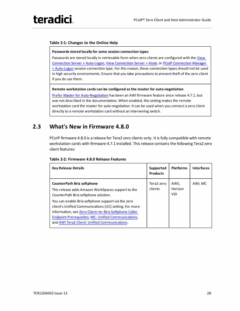
Table 2-1: Changes to the Online Help
Passwords stored locally for some session connection typesPasswords are stored locally in retrievable form when zero clients are configured with the ViewConnection Server + Auto-Logon, View Connection Server + Kiosk, or PCoIP Connection Manager+ Auto-Logon session connection type. For this reason, these connection types should not be usedin high security environments. Ensure that you take precautions to prevent theft of the zero clientif you do use them.
Remote workstation cards can be configured as the master for auto-negotiationPrefer Master for Auto-Negotiation has been an AWI firmware feature since release 4.7.1, butwas not described in the documentation. When enabled, this setting makes the remoteworkstation card the master for auto-negotiation. It can be used when you connect a zero clientdirectly to a remote workstation card without an intervening switch.
2.3 What's New in Firmware 4.8.0
PCoIP firmware 4.8.0 is a release for Tera2 zero clients only. It is fully compatible with remoteworkstation cards with firmware 4.7.1 installed. This release contains the following Tera2 zeroclient features:
Table 2-2: Firmware 4.8.0 Release Features
Key Release Details SupportedProducts
Platforms Interfaces
CounterPath Bria softphoneThis release adds Amazon WorkSpaces support to theCounterPath Bria softphone solution.You can enable Bria softphone support via the zeroclient's Unified Communications (UC) setting. For moreinformation, see Zero Client–to–Bria Softphone CallerEndpoint Prerequisites, MC: Unified Communications,and AWI Tera2 Client: Unified Communications.
Tera2 zeroclients
AWS,HorizonVDI
AWI, MC
TER1206003 Issue 13 28
PCoIP® Zero Client and Host Administrator Guide
Key Release Details SupportedProducts
Platforms Interfaces
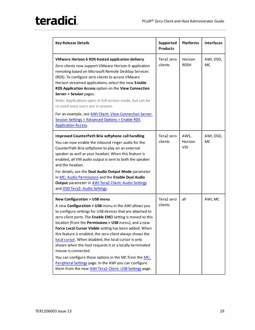
VMware Horizon 6 RDS-hosted application deliveryZero clients now support VMware Horizon 6 applicationremoting based on Microsoft Remote Desktop Services(RDS). To configure zero clients to access VMwareHorizon streamed applications, select the new EnableRDS Application Access option on the View ConnectionServer > Session pages.Note: Applications open in full-screen mode, but can bere-sized once users are in session.
For an example, see AWI Client: View Connection ServerSession Settings > Advanced Options > Enable RDSApplication Access.
Tera2 zeroclients
HorizonRDSH
AWI, OSD,MC
Improved CounterPath Bria softphone call handlingYou can now enable the inbound ringer audio for theCounterPath Bria softphone to play on an externalspeaker as well as your headset. When this feature isenabled, all VM audio output is sent to both the speakerand the headset.For details, see the Dual Audio Output Mode parameterin MC: Audio Permissions and the Enable Dual AudioOutput parameter in AWI Tera2 Client: Audio Settingsand OSD Tera2: Audio Settings.
Tera2 zeroclients
AWS,HorizonVDI
AWI, OSD,MC
New Configuration > USBmenuA new Configuration > USBmenu in the AWI allows youto configure settings for USB devices that are attached tozero client ports. The Enable EHCI setting is moved to thislocation (from the Permissions > USBmenu), and a newForce Local Cursor Visible setting has been added. Whenthis feature is enabled, the zero client always shows thelocal cursor. When disabled, the local cursor is onlyshown when the host requests it or a locally-terminatedmouse is connected.You can configure these options in the MC from the MC:Peripheral Settings page. In the AWI you can configurethem from the new AWI Tera2 Client: USB Settings page.
Tera2 zeroclients
all AWI, MC
TER1206003 Issue 13 29
PCoIP® Zero Client and Host Administrator Guide
Key Release Details SupportedProducts
Platforms Interfaces
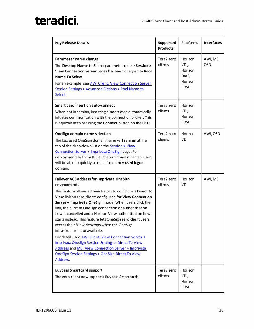
Parameter name changeThe Desktop Name to Select parameter on the Session >View Connection Server pages has been changed to PoolName To Select.For an example, see AWI Client: View Connection ServerSession Settings > Advanced Options > Pool Name toSelect.
Tera2 zeroclients
HorizonVDI,HorizonDaaS,HorizonRDSH
AWI, MC,OSD
Smart card insertion auto-connectWhen not in session, inserting a smart card automaticallyinitiates communication with the connection broker. Thisis equivalent to pressing the Connect button on the OSD.
Tera2 zeroclients
HorizonVDI,HorizonRDSH
OneSign domain name selectionThe last used OneSign domain name will remain at thetop of the drop-down list on the Session > ViewConnection Server + Imprivata OneSign page. Fordeployments with multiple OneSign domain names, userswill be able to quickly select a frequently used logondomain.
Tera2 zeroclients
HorizonVDI
AWI, OSD
Failover VCS address for Imprivata OneSignenvironmentsThis feature allows administrators to configure a Direct toView link on zero clients configured for View ConnectionServer + Imprivata OneSignmode. When users click thelink, the current OneSign connection or authenticationflow is cancelled and a Horizon View authentication flowstarts instead. This feature lets OneSign zero client usersaccess their View desktops when the OneSigninfrastructure is unavailable.For details, see AWI Client: View Connection Server +Imprivata OneSign Session Settings > Direct To ViewAddress and MC: View Connection Server + ImprivataOneSign Session Settings > OneSign Direct To ViewAddress.
Tera2 zeroclients
HorizonVDI
AWI, MC
Buypass Smartcard supportThe zero client now supports Buypass Smartcards.
Tera2 zeroclients
HorizonVDI,HorizonRDSH
TER1206003 Issue 13 30
PCoIP® Zero Client and Host Administrator Guide
Key Release Details SupportedProducts
Platforms Interfaces
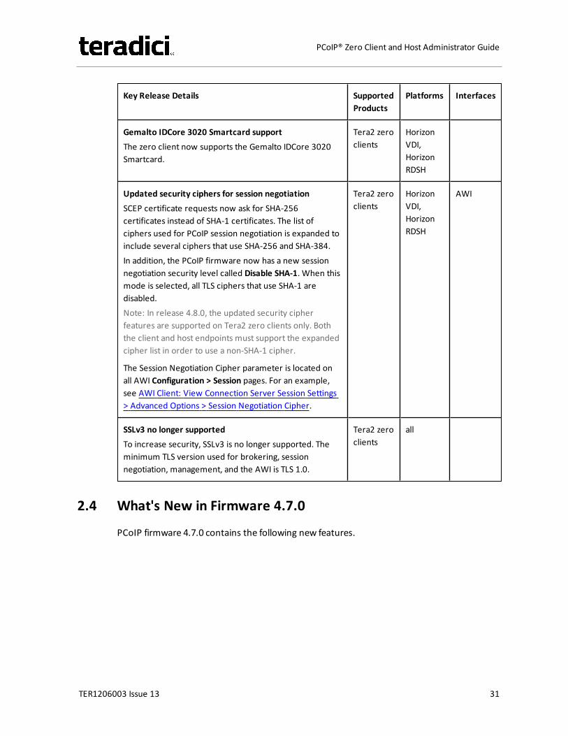
Gemalto IDCore 3020 Smartcard supportThe zero client now supports the Gemalto IDCore 3020Smartcard.
Tera2 zeroclients
HorizonVDI,HorizonRDSH
Updated security ciphers for session negotiationSCEP certificate requests now ask for SHA-256certificates instead of SHA-1 certificates. The list ofciphers used for PCoIP session negotiation is expanded toinclude several ciphers that use SHA-256 and SHA-384.In addition, the PCoIP firmware now has a new sessionnegotiation security level called Disable SHA-1. When thismode is selected, all TLS ciphers that use SHA-1 aredisabled.Note: In release 4.8.0, the updated security cipherfeatures are supported on Tera2 zero clients only. Boththe client and host endpoints must support the expandedcipher list in order to use a non-SHA-1 cipher.
The Session Negotiation Cipher parameter is located onall AWI Configuration > Session pages. For an example,see AWI Client: View Connection Server Session Settings> Advanced Options > Session Negotiation Cipher.
Tera2 zeroclients
HorizonVDI,HorizonRDSH
AWI
SSLv3 no longer supportedTo increase security, SSLv3 is no longer supported. Theminimum TLS version used for brokering, sessionnegotiation, management, and the AWI is TLS 1.0.
Tera2 zeroclients
all
2.4 What's New in Firmware 4.7.0
PCoIP firmware 4.7.0 contains the following new features.
TER1206003 Issue 13 31
PCoIP® Zero Client and Host Administrator Guide
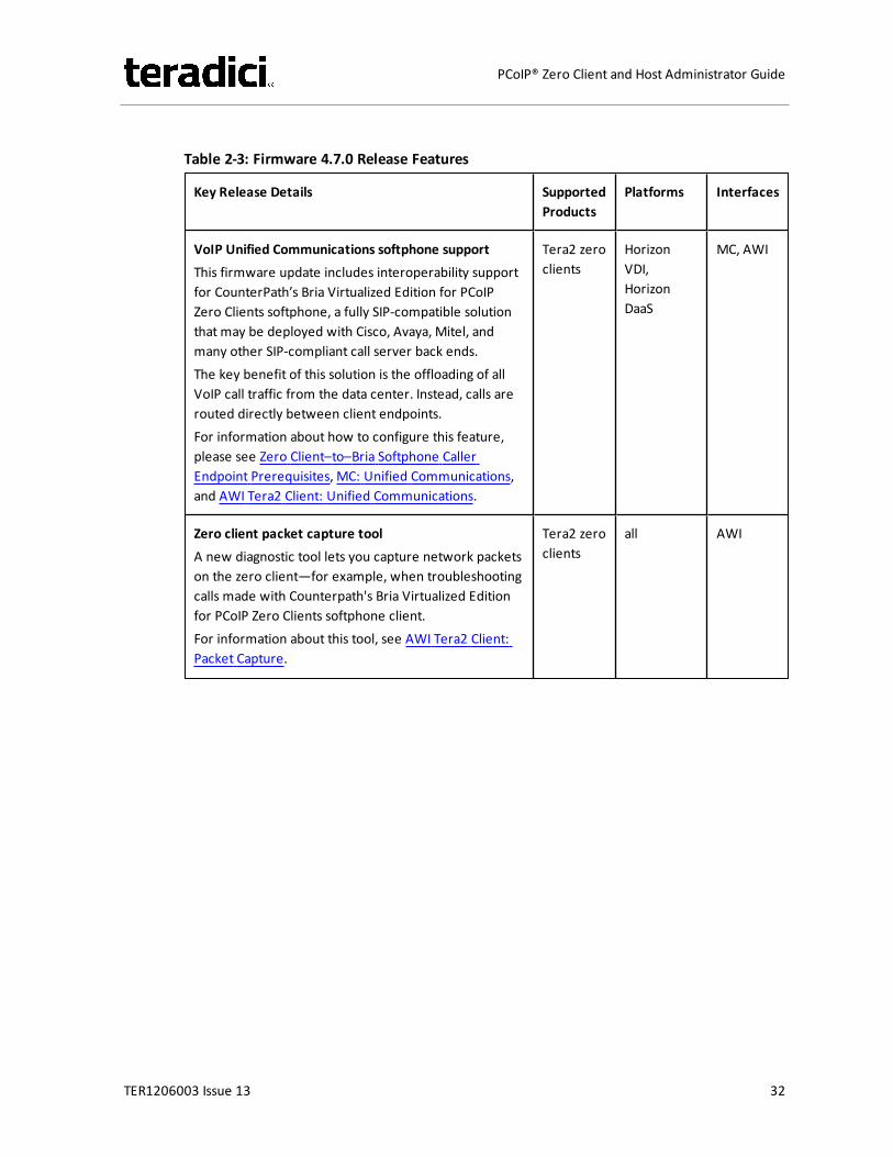
Table 2-3: Firmware 4.7.0 Release Features
Key Release Details SupportedProducts
Platforms Interfaces
VoIP Unified Communications softphone supportThis firmware update includes interoperability supportfor CounterPath’s Bria Virtualized Edition for PCoIPZero Clients softphone, a fully SIP-compatible solutionthat may be deployed with Cisco, Avaya, Mitel, andmany other SIP-compliant call server back ends.The key benefit of this solution is the offloading of allVoIP call traffic from the data center. Instead, calls arerouted directly between client endpoints.For information about how to configure this feature,please see Zero Client–to–Bria Softphone CallerEndpoint Prerequisites, MC: Unified Communications,and AWI Tera2 Client: Unified Communications.
Tera2 zeroclients
HorizonVDI,HorizonDaaS
MC, AWI
Zero client packet capture toolA new diagnostic tool lets you capture network packetson the zero client—for example, when troubleshootingcalls made with Counterpath's Bria Virtualized Editionfor PCoIP Zero Clients softphone client.For information about this tool, see AWI Tera2 Client:Packet Capture.
Tera2 zeroclients
all AWI
TER1206003 Issue 13 32
PCoIP® Zero Client and Host Administrator Guide
Key Release Details SupportedProducts
Platforms Interfaces
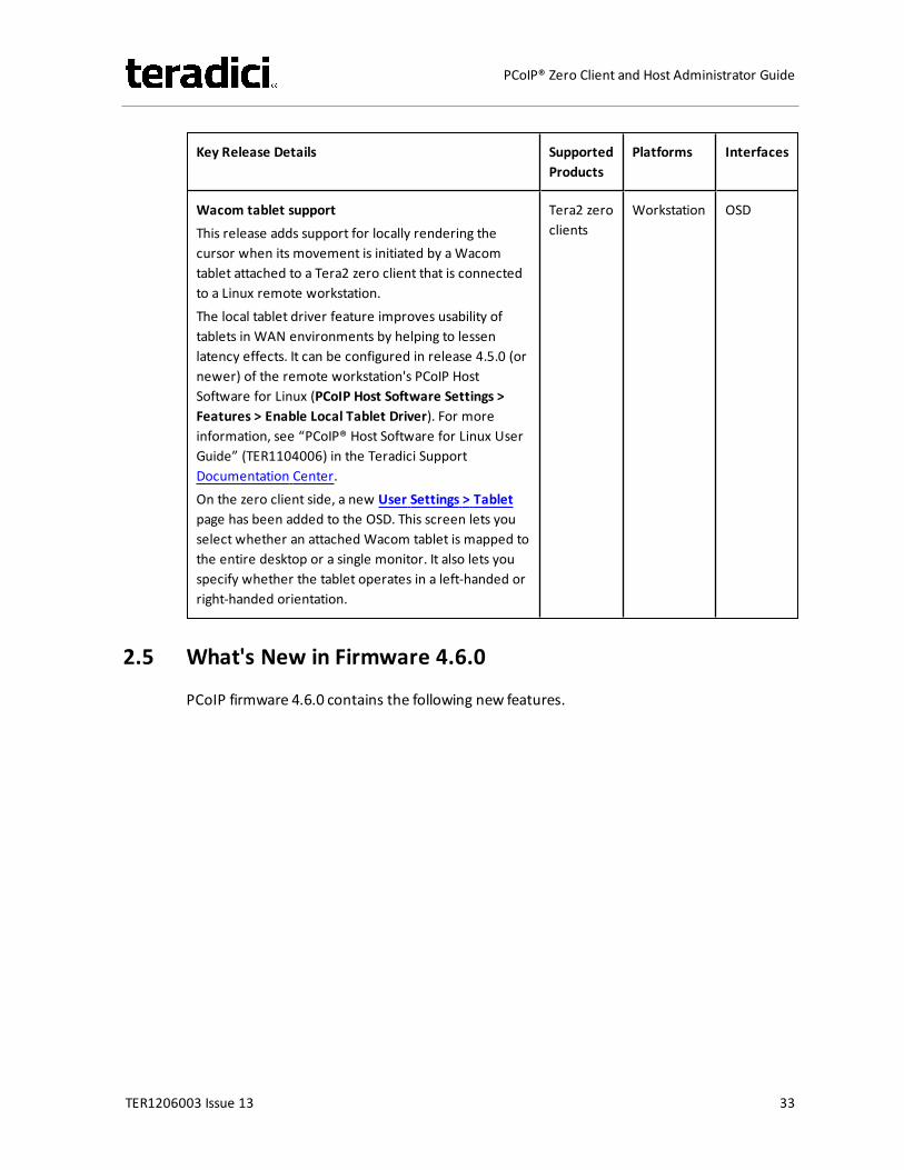
Wacom tablet supportThis release adds support for locally rendering thecursor when its movement is initiated by aWacomtablet attached to a Tera2 zero client that is connectedto a Linux remote workstation.The local tablet driver feature improves usability oftablets in WAN environments by helping to lessenlatency effects. It can be configured in release 4.5.0 (ornewer) of the remote workstation's PCoIP HostSoftware for Linux (PCoIP Host Software Settings >Features > Enable Local Tablet Driver). For moreinformation, see “PCoIP® Host Software for Linux UserGuide” (TER1104006) in the Teradici SupportDocumentation Center.On the zero client side, a new User Settings > Tabletpage has been added to the OSD. This screen lets youselect whether an attached Wacom tablet is mapped tothe entire desktop or a single monitor. It also lets youspecify whether the tablet operates in a left-handed orright-handed orientation.
Tera2 zeroclients
Workstation OSD
2.5 What's New in Firmware 4.6.0
PCoIP firmware 4.6.0 contains the following new features.
TER1206003 Issue 13 33
PCoIP® Zero Client and Host Administrator Guide
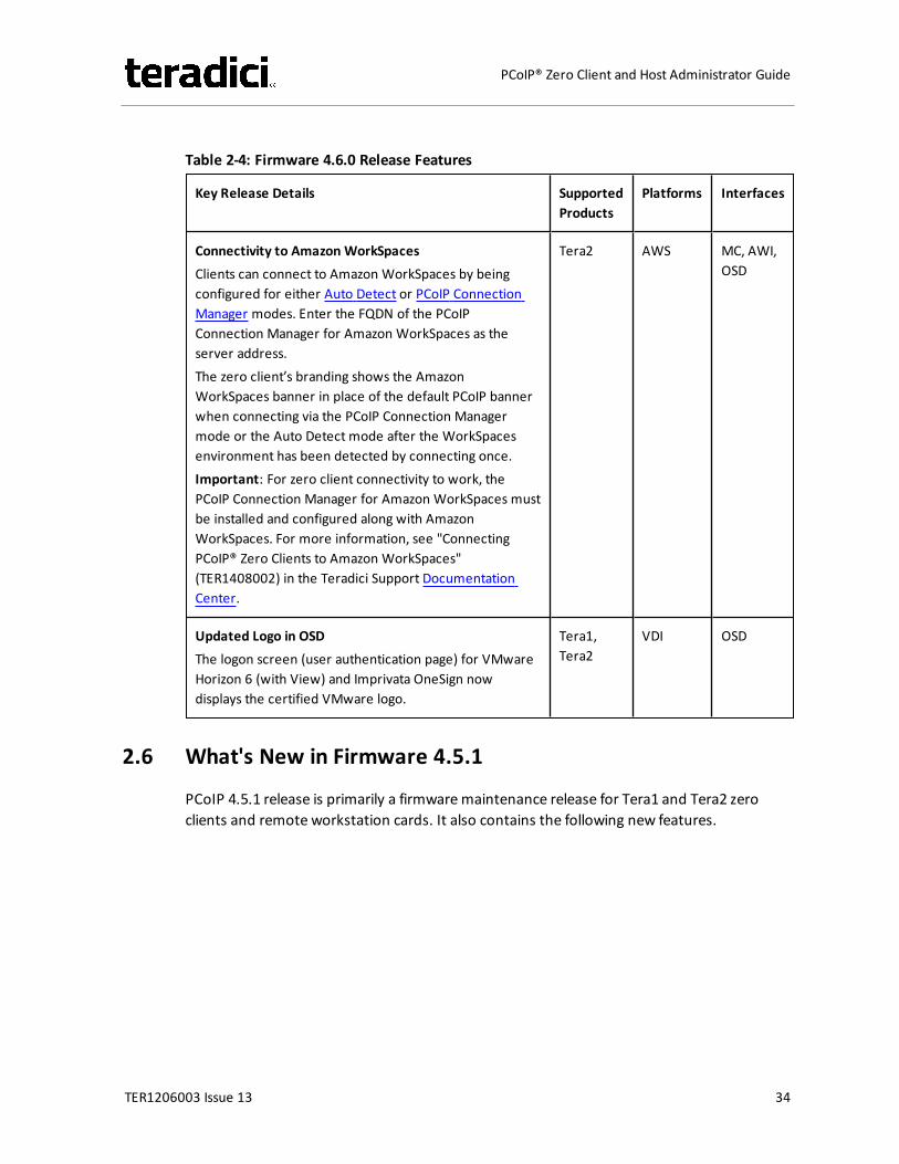
Table 2-4: Firmware 4.6.0 Release Features
Key Release Details SupportedProducts
Platforms Interfaces
Connectivity to Amazon WorkSpacesClients can connect to Amazon WorkSpaces by beingconfigured for either Auto Detect or PCoIP ConnectionManager modes. Enter the FQDN of the PCoIPConnection Manager for Amazon WorkSpaces as theserver address.The zero client’s branding shows the AmazonWorkSpaces banner in place of the default PCoIP bannerwhen connecting via the PCoIP Connection Managermode or the Auto Detect mode after the WorkSpacesenvironment has been detected by connecting once.Important: For zero client connectivity to work, thePCoIP Connection Manager for Amazon WorkSpaces mustbe installed and configured along with AmazonWorkSpaces. For more information, see "ConnectingPCoIP® Zero Clients to Amazon WorkSpaces"(TER1408002) in the Teradici Support DocumentationCenter.
Tera2 AWS MC, AWI,OSD
Updated Logo in OSDThe logon screen (user authentication page) for VMwareHorizon 6 (with View) and Imprivata OneSign nowdisplays the certified VMware logo.
Tera1,Tera2
VDI OSD
2.6 What's New in Firmware 4.5.1
PCoIP 4.5.1 release is primarily a firmwaremaintenance release for Tera1 and Tera2 zeroclients and remote workstation cards. It also contains the following new features.
TER1206003 Issue 13 34
PCoIP® Zero Client and Host Administrator Guide
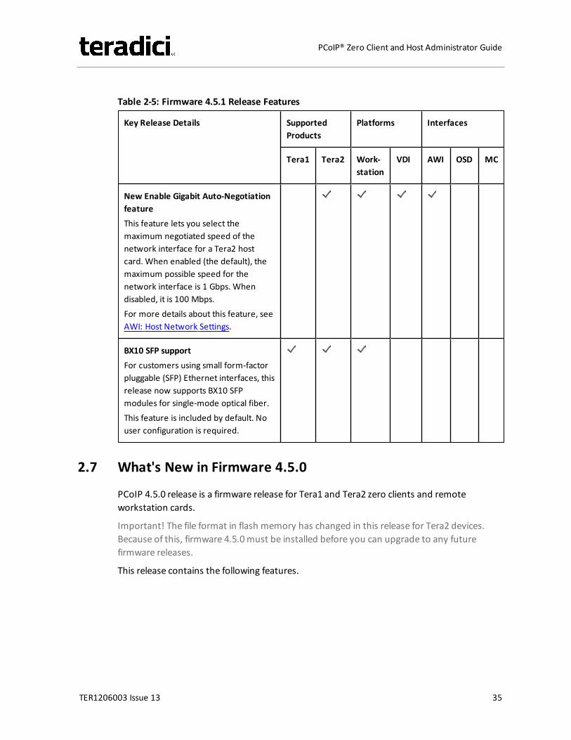
Table 2-5: Firmware 4.5.1 Release Features
Key Release Details SupportedProducts
Platforms Interfaces
Tera1 Tera2 Work-station
VDI AWI OSD MC
New Enable Gigabit Auto-NegotiationfeatureThis feature lets you select themaximum negotiated speed of thenetwork interface for a Tera2 hostcard. When enabled (the default), themaximum possible speed for thenetwork interface is 1 Gbps. Whendisabled, it is 100 Mbps.For more details about this feature, seeAWI: Host Network Settings.
BX10 SFP supportFor customers using small form-factorpluggable (SFP) Ethernet interfaces, thisrelease now supports BX10 SFPmodules for single-mode optical fiber.This feature is included by default. Nouser configuration is required.
2.7 What's New in Firmware 4.5.0
PCoIP 4.5.0 release is a firmware release for Tera1 and Tera2 zero clients and remoteworkstation cards.
Important! The file format in flash memory has changed in this release for Tera2 devices.Because of this, firmware 4.5.0must be installed before you can upgrade to any futurefirmware releases.
This release contains the following features.
TER1206003 Issue 13 35
PCoIP® Zero Client and Host Administrator Guide
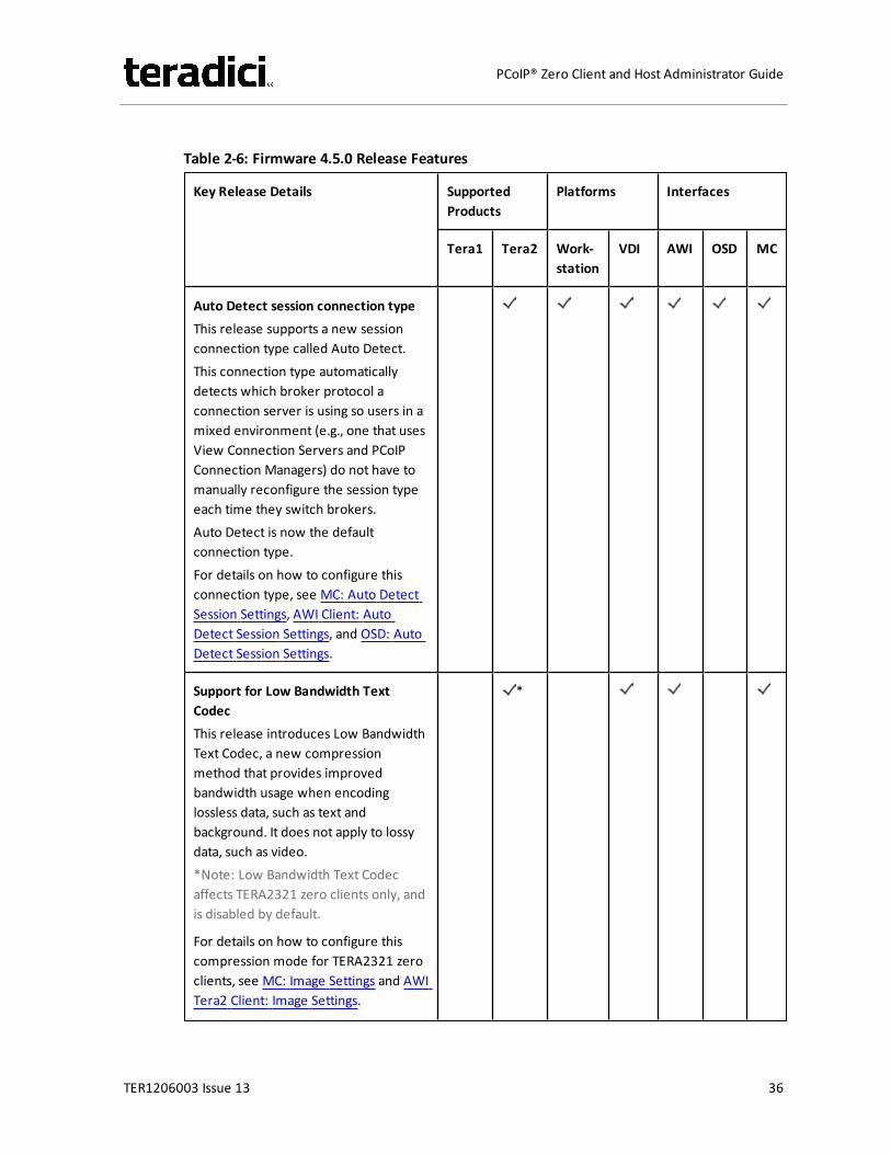
Table 2-6: Firmware 4.5.0 Release Features
Key Release Details SupportedProducts
Platforms Interfaces
Tera1 Tera2 Work-station
VDI AWI OSD MC
Auto Detect session connection typeThis release supports a new sessionconnection type called Auto Detect.This connection type automaticallydetects which broker protocol aconnection server is using so users in amixed environment (e.g., one that usesView Connection Servers and PCoIPConnection Managers) do not have tomanually reconfigure the session typeeach time they switch brokers.Auto Detect is now the defaultconnection type.For details on how to configure thisconnection type, see MC: Auto DetectSession Settings, AWI Client: AutoDetect Session Settings, and OSD: AutoDetect Session Settings.
Support for Low Bandwidth TextCodecThis release introduces Low BandwidthText Codec, a new compressionmethod that provides improvedbandwidth usage when encodinglossless data, such as text andbackground. It does not apply to lossydata, such as video.*Note: Low Bandwidth Text Codecaffects TERA2321 zero clients only, andis disabled by default.
For details on how to configure thiscompression mode for TERA2321 zeroclients, see MC: Image Settings and AWITera2 Client: Image Settings.
*
TER1206003 Issue 13 36
PCoIP® Zero Client and Host Administrator Guide
Key Release Details SupportedProducts
Platforms Interfaces
Tera1 Tera2 Work-station
VDI AWI OSD MC
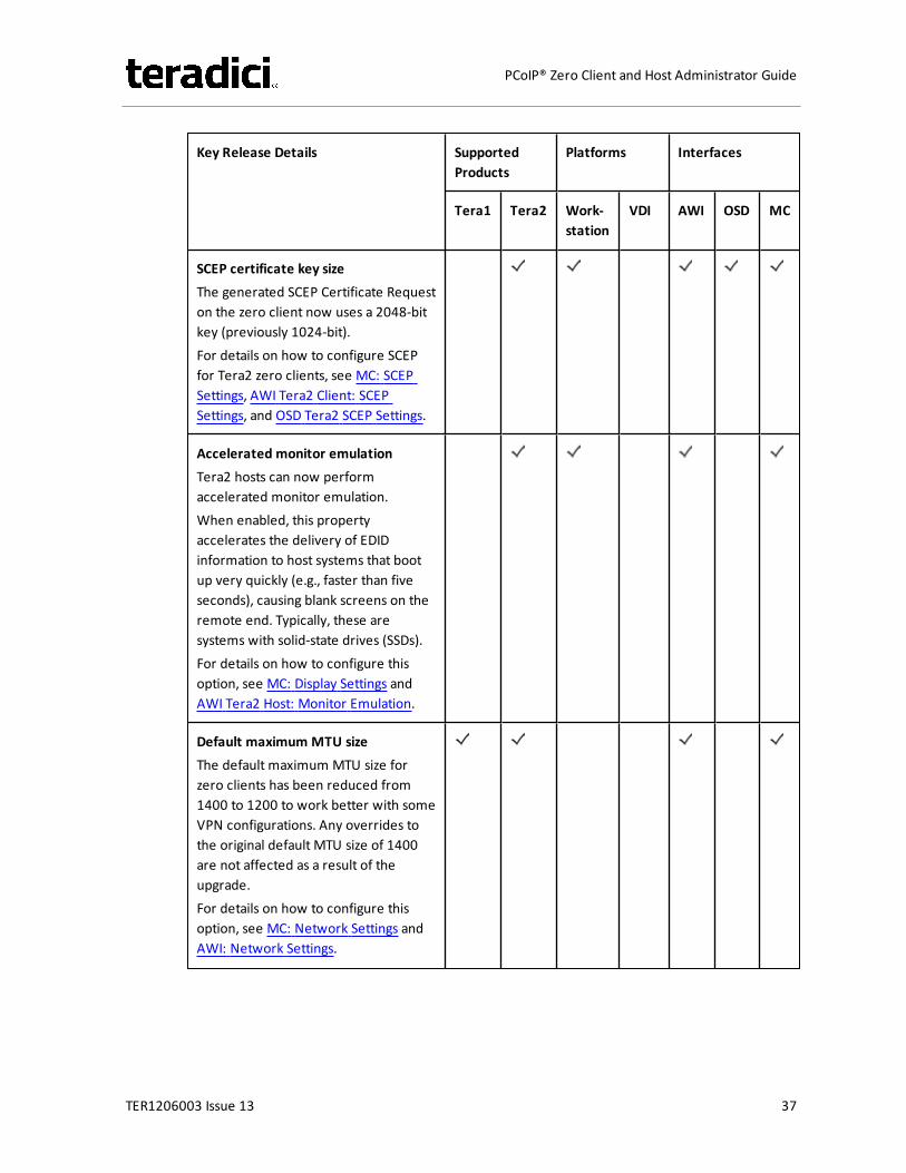
SCEP certificate key sizeThe generated SCEP Certificate Requeston the zero client now uses a 2048-bitkey (previously 1024-bit).For details on how to configure SCEPfor Tera2 zero clients, see MC: SCEPSettings, AWI Tera2 Client: SCEPSettings, and OSD Tera2 SCEP Settings.
Accelerated monitor emulationTera2 hosts can now performaccelerated monitor emulation.When enabled, this propertyaccelerates the delivery of EDIDinformation to host systems that bootup very quickly (e.g., faster than fiveseconds), causing blank screens on theremote end. Typically, these aresystems with solid-state drives (SSDs).For details on how to configure thisoption, see MC: Display Settings andAWI Tera2 Host: Monitor Emulation.
Default maximum MTU sizeThe default maximum MTU size forzero clients has been reduced from1400 to 1200 to work better with someVPN configurations. Any overrides tothe original default MTU size of 1400are not affected as a result of theupgrade.For details on how to configure thisoption, see MC: Network Settings andAWI: Network Settings.
TER1206003 Issue 13 37
PCoIP® Zero Client and Host Administrator Guide
Key Release Details SupportedProducts
Platforms Interfaces
Tera1 Tera2 Work-station
VDI AWI OSD MC
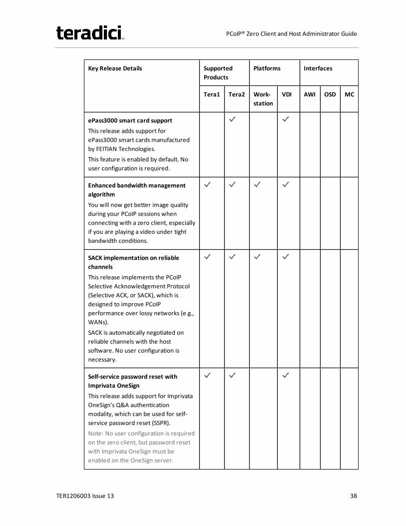
ePass3000 smart card supportThis release adds support forePass3000 smart cards manufacturedby FEITIAN Technologies.This feature is enabled by default. Nouser configuration is required.
Enhanced bandwidth managementalgorithmYou will now get better image qualityduring your PCoIP sessions whenconnecting with a zero client, especiallyif you are playing a video under tightbandwidth conditions.
SACK implementation on reliablechannelsThis release implements the PCoIPSelective Acknowledgement Protocol(Selective ACK, or SACK), which isdesigned to improve PCoIPperformance over lossy networks (e.g.,WANs).SACK is automatically negotiated onreliable channels with the hostsoftware. No user configuration isnecessary.
Self-service password reset withImprivata OneSignThis release adds support for ImprivataOneSign's Q&A authenticationmodality, which can be used for self-service password reset (SSPR).Note: No user configuration is requiredon the zero client, but password resetwith Imprivata OneSign must beenabled on the OneSign server.
TER1206003 Issue 13 38
PCoIP® Zero Client and Host Administrator Guide
Key Release Details SupportedProducts
Platforms Interfaces
Tera1 Tera2 Work-station
VDI AWI OSD MC
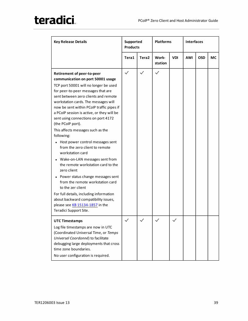
Retirement of peer-to-peercommunication on port 50001 usageTCP port 50001 will no longer be usedfor peer-to-peer messages that aresent between zero clients and remoteworkstation cards. The messages willnow be sent within PCoIP traffic pipes ifa PCoIP session is active, or they will besent using connections on port 4172(the PCoIP port).This affects messages such as thefollowing:l Host power control messages sent
from the zero client to remoteworkstation card
l Wake-on-LAN messages sent fromthe remote workstation card to thezero client
l Power status change messages sentfrom the remote workstation cardto the zer client
For full details, including informationabout backward compatibility issues,please see KB 15134-1857 in theTeradici Support Site.
UTC TimestampsLog file timestamps are now in UTC(Coordinated Universal Time, or TempsUniversel Coordonné) to facilitatedebugging large deployments that crosstime zone boundaries.No user configuration is required.
TER1206003 Issue 13 39
PCoIP® Zero Client and Host Administrator Guide
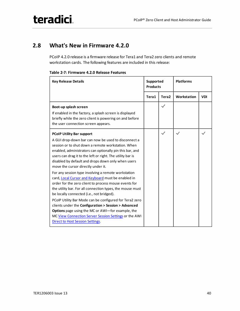
2.8 What's New in Firmware 4.2.0
PCoIP 4.2.0 release is a firmware release for Tera1 and Tera2 zero clients and remoteworkstation cards. The following features are included in this release:
Table 2-7: Firmware 4.2.0 Release Features
Key Release Details SupportedProducts
Platforms
Tera1 Tera2 Workstation VDI
Boot-up splash screenIf enabled in the factory, a splash screen is displayedbriefly while the zero client is powering on and beforethe user connection screen appears.
PCoIP Utility Bar supportA GUI drop-down bar can now be used to disconnect asession or to shut down a remote workstation. Whenenabled, administrators can optionally pin this bar, andusers can drag it to the left or right. The utility bar isdisabled by default and drops down only when usersmove the cursor directly under it.For any session type involving a remote workstationcard, Local Cursor and Keyboard must be enabled inorder for the zero client to process mouse events forthe utility bar. For all connection types, the mouse mustbe locally connected (i.e., not bridged).PCoIP Utility Bar Mode can be configured for Tera2 zeroclients under the Configuration > Session > AdvancedOptions page using the MC or AWI—for example, theMC View Connection Server Session Settings or the AWIDirect to Host Session Settings.
TER1206003 Issue 13 40
PCoIP® Zero Client and Host Administrator Guide
Key Release Details SupportedProducts
Platforms
Tera1 Tera2 Workstation VDI
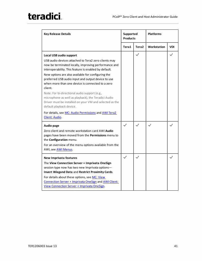
Local USB audio supportUSB audio devices attached to Tera2 zero clients maynow be terminated locally, improving performance andinteroperability. This feature is enabled by default.New options are also available for configuring thepreferred USB audio input and output device to usewhen more than one device is connected to a zeroclient.Note: For bi-directional audio support (e.g.,microphone as well as playback), the Teradici AudioDriver must be installed on your VM and selected as thedefault playback device.
For details, see MC: Audio Permissions and AWI Tera2Client: Audio.
Audio pageZero client and remote workstation card AWI Audiopages have been moved from the Permissionsmenu tothe Configurationmenu.For an overview of the menu options available from theAWI, see AWIMenus.
New Imprivata featuresThe View Connection Server + Imprivata OneSignsession type now has two new Imprivata options—Invert Wiegand Data and Restrict Proximity Cards.For details about these options, see MC: ViewConnection Server + Imprivata OneSign and AWI Client:View Connection Server + Imprivata OneSign.
TER1206003 Issue 13 41
PCoIP® Zero Client and Host Administrator Guide
Key Release Details SupportedProducts
Platforms
Tera1 Tera2 Workstation VDI
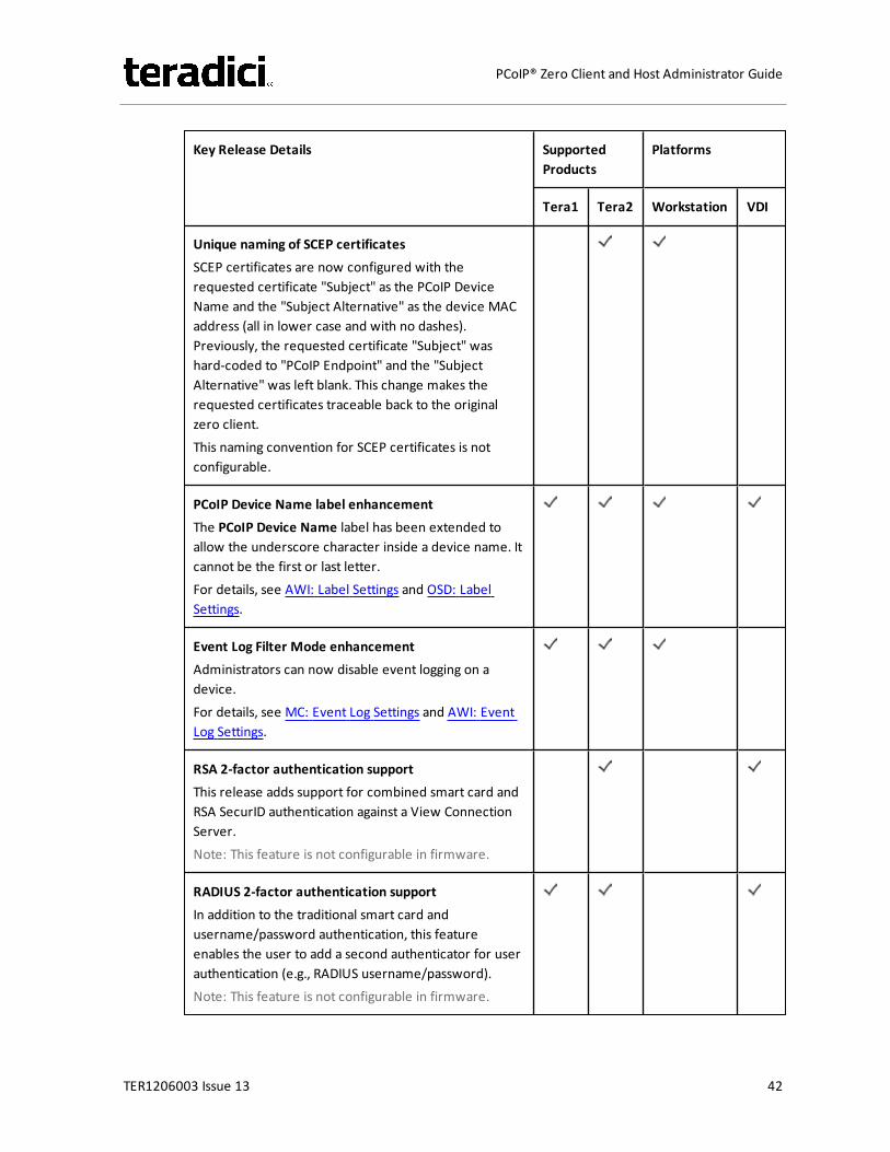
Unique naming of SCEP certificatesSCEP certificates are now configured with therequested certificate "Subject" as the PCoIP DeviceName and the "Subject Alternative" as the device MACaddress (all in lower case and with no dashes).Previously, the requested certificate "Subject" washard-coded to "PCoIP Endpoint" and the "SubjectAlternative" was left blank. This change makes therequested certificates traceable back to the originalzero client.This naming convention for SCEP certificates is notconfigurable.
PCoIP Device Name label enhancementThe PCoIP Device Name label has been extended toallow the underscore character inside a device name. Itcannot be the first or last letter.For details, see AWI: Label Settings and OSD: LabelSettings.
Event Log Filter Mode enhancementAdministrators can now disable event logging on adevice.For details, see MC: Event Log Settings and AWI: EventLog Settings.
RSA 2-factor authentication supportThis release adds support for combined smart card andRSA SecurID authentication against a View ConnectionServer.Note: This feature is not configurable in firmware.
RADIUS 2-factor authentication supportIn addition to the traditional smart card andusername/password authentication, this featureenables the user to add a second authenticator for userauthentication (e.g., RADIUS username/password).Note: This feature is not configurable in firmware.
TER1206003 Issue 13 42
PCoIP® Zero Client and Host Administrator Guide
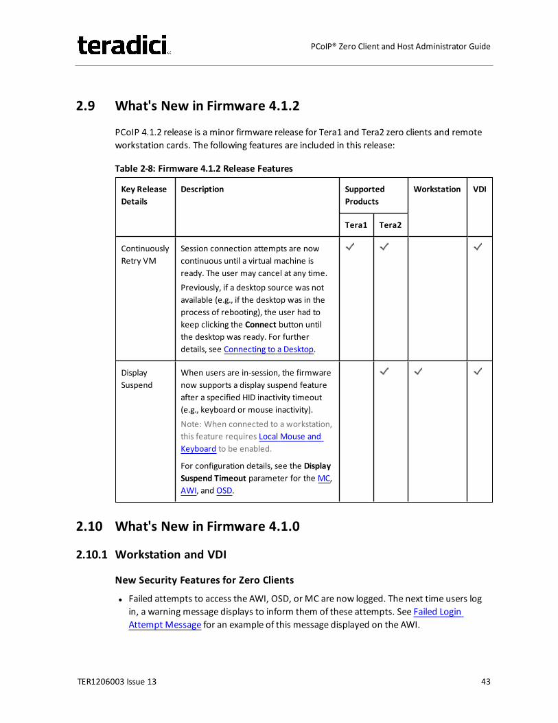
2.9 What's New in Firmware 4.1.2
PCoIP 4.1.2 release is a minor firmware release for Tera1 and Tera2 zero clients and remoteworkstation cards. The following features are included in this release:
Table 2-8: Firmware 4.1.2 Release Features
Key ReleaseDetails
Description SupportedProducts
Workstation VDI
Tera1 Tera2
ContinuouslyRetry VM
Session connection attempts are nowcontinuous until a virtual machine isready. The user may cancel at any time.Previously, if a desktop source was notavailable (e.g., if the desktop was in theprocess of rebooting), the user had tokeep clicking the Connect button untilthe desktop was ready. For furtherdetails, see Connecting to a Desktop.
DisplaySuspend
When users are in-session, the firmwarenow supports a display suspend featureafter a specified HID inactivity timeout(e.g., keyboard or mouse inactivity).Note: When connected to a workstation,this feature requires Local Mouse andKeyboard to be enabled.
For configuration details, see the DisplaySuspend Timeout parameter for the MC,AWI, and OSD.
2.10 What's New in Firmware 4.1.0
2.10.1 Workstation and VDI
New Security Features for Zero Clients
l Failed attempts to access the AWI, OSD, or MC are now logged. The next time users login, a warning message displays to inform them of these attempts. See Failed LoginAttempt Message for an example of this message displayed on the AWI.
TER1206003 Issue 13 43
PCoIP® Zero Client and Host Administrator Guide
l After three failed attempts to access the AWI or OSD, each subsequent failed attempt willrequire additional time to complete.
l A newAccess page containing the following features is available for the AWI and OSD:l You can now disable AWI and/or MC access to a zero client to prevent changes to the
client's configuration.Note: If the Options > Configuration menus on the OSD are also hidden for the zeroclient, then only one of thesemanagement tools can be disabled at any one time.
l You can force the changing of the administrative password the next time the AWI orOSD is accessed.
l Simple Certificate Enrollment Protocol (SCEP) is now supported for Tera2 zero clients.From the new SCEP page for the AWI and OSD, you can configure a zero client toautomatically obtain certificates from a SCEP server. From the newMC SCEP page, youcan configure a profile to obtain certificates for a group of zero clients.
Other New Features
l Session pages for all management tools have the following new options:l For Tera2 zero clients, two new session connection types (PCoIP Connection Manager
and PCoIP Connection Manager + Auto-Logon) have been added. You can configurethis feature from thec AWI, OSD, and MC Session pages.Note: The PCoIP Connection Manager can be used in the future to broker PCoIPsessions.
l For all zero client and remote workstation card session connection types, you cannow populate the Differentiated Services Code Point (DSCP) field in the IP header toallow intermediate network nodes to prioritize PCoIP traffic accordingly. You can alsoenable transport congestion notification to allow PCoIP endpoints to reactaccordingly if an intermediate network node sets the congestion notification bit ineither the IP header or PCoIP transport header. These settings are available at thebottom of the Advanced Options section on all Session pages.
l Themaximum size for certificates has been increased in this release. From the AWI, themaximum certificate size you can upload to a zero client or remote workstation card isnow 10,239 bytes (up from 6,143 bytes). From theMC, themaximum certificate size youcan upload to a profile is now 8,176 (up from 6,143 bytes). You can upload up to 16certificates per device as long as themaximum storage space of 98,112 bytes is notexceeded. Note that if SCEP is enabled, you can only upload a maximum of 14 additionalcertificates since the SCEP server always installs two certificates in a device.
l The zero client and remote workstation card Power pages have been moved from theAWI Permissionsmenu to the Configurationmenu and have the following new settings:l For zero clients, you can now configure a screen saver timeout to put attached
displays in low-power mode after a specified period of inactivity. For Tera2 zero clientsthat support powering off, you can configure an auto power-off timeout to powerdown the client after a period of inactivity when users are not in session. TheMC
TER1206003 Issue 13 44
PCoIP® Zero Client and Host Administrator Guide
Power page also has the new auto power-off timeout option for a Tera2 zero clientprofile.
l For Tera2 remote workstation cards, you can select whether to wake up the host fromsleep mode using the remote power button input or the PCIe bus input.
l The following new display features are included in this release:l A new display cloning mode for TERA2321 zero clients lets you mirror images on the
primary display to the secondary display (e.g., for multiple digital signs). You canenable display cloning from the OSD Display page, or you can configure a profile forTERA2321 zero clients with this feature from theMC Display page.
l For Tera2 remote workstation cards, you can now enable a host hot plug delay toresolve black screen issues with certain Linux GPU driver timing expectations. Thisfeature is available from the AWI Monitor Emulation page, or you can configure aprofile for Tera2 remote workstation cards with this feature from theMC Display page.
l Portuguese (Brazilian ABNT) and Slovak (AWERTY and AWERTZ) keyboard layouts are nowsupported for Tera1 and Tera2 zero clients.
2.10.2 VDI-specificl The following smart cards and eToken devices are now supported:
l SafeNet SC650 smart cards with SafeNet PKI applet and SHAC middleware (Tera1 andTera2 zero clients)
l Atos CardOS smart cards (Tera2 zero clients only)l eToken 72k Pro USB user authentication devices (Tera1 and Tera2 zero clients)
l A newUse Existing Setting option has been added to specify whether the proximity cardreader beeps when a valid card is tapped on the reader. When selected, this option usesthe proximity card setting that has been configured outside of the zero client. This featureis available from the AWI View Connection Server + Imprivata OneSign Session page (Pre-session Reader Beep field), or you can configure a profile for zero clients with this featurefrom theMC View Connection Server + Imprivata OneSign Session page (ProximityReader Beep Mode field).
2.10.3 Workstation-specificl You can now configure "host wake" options from the OSD Direct to Host Session page.
Previously, this feature was only available on the AWI and MC.l Local termination of keyboards and mice behind USB hubs is now supported provided all
devices attached to USB hub are HID keyboards and mice.
2.11 What's New in Firmware 4.0.3
The Teradici firmware 4.0.3 release supports the new Tera2 processor family to deliverenhanced display capabilities, imaging performance, memory, power management, and
TER1206003 Issue 13 45
PCoIP® Zero Client and Host Administrator Guide
other important functions.
For example, the TERA2140 zero client can support up to four displays (DVI-D or DisplayPort)and can perform image encoding at speeds of up to 300million pixels per second (Mpps) forremote workstations and 50Mpps for virtual desktops. For complete product details onsecond-generation PCoIP zero clients and remote workstation cards containing these newTera2 processors, see the Teradici website at http://www.teradici.com. For a list of all theremote workstation cards and zero clients supported in this firmware release, see PCoIPEndpoints.
Note: For the Tera1 processor family, please use the firmware 4.0.2 release.
2.12 What's New in Firmware 4.0.2
The Teradici firmware 4.0.2 release provides the following features and enhancements:
l Processor family information: You can now display information about the processorfamily and chipset in your device a number of ways. For details, see Displaying ProcessorInformation.
l Display topology configuration enhancements: To support the new Tera2 displaycapabilities, the Display Topology Configuration page on theManagement Console (MC)and the Display Topology settings on the On Screen Display (OSD) now let you configurelayout, alignment, and resolution properties for dual-display and quad-displaytopologies.
l Preferred resolution override enhancements: In this release, an expanded list of defaultresolutions is included when you configure a zero client to advertise default ExtendedDisplay Identification Data (EDID) information to the graphics processing unit (GPU) in ahost workstation. For Tera2 clients, you can now configure preferred (default) resolutionsfor up to four displays. For details, see OSD Tera2: Display Settings.
l Expanded list of test display resolutions: TheDisplay page on the Administrator WebInterface (AWI) now contains an expanded list of display resolutions for viewing a testpattern on a zero client. For details about how to configure a test pattern, see AWI Client:Display Settings.
l New Tera2 disconnect options: When a user is in a session with a remote workstation,pressing the connect/disconnect button on a Tera2 zero client pops up a new dialog thatlets the user select whether to disconnect from the session or to power off the remoteworkstation. Users can also use a Ctrl+Alt+F12 hotkey sequence to display this pop-updialog. For details about this new feature, see Disconnecting from a Session.
TER1206003 Issue 13 46
PCoIP® Zero Client and Host Administrator Guide
l Enhanced OSD messaging: Messaging on the OSD has been enhanced with new overlaywindows and also new in-linemessages that appear on the OSD's Connect page. Forexample, if a user does not enter the correct user name or password, or if the Caps Lockkey is on, a message displays above the Connect button on this page to alert the user.Network connection lost/down/up messages also display in this location, replacing thenetwork icons that used to appear in the lower right-hand corner. For details, seeConnecting to a Session and Overlay Windows.
l Management Console cached VCS address enhancement: You can now configure up to25 cached View Connection Server addresses from theManagement Console's SessionConfiguration – View Connection Server page. These servers are displayed in a drop-down list on the OSD Connect page when users use a VMware View Connection Server toconnect to a virtual desktop. For details, seeMC: View Connection Server SessionSettings.
l Imprivata OneSign configuration enhancements: New parameters on the ViewConnection Server – Imprivata OneSign page allow you to configure a OneSign serverdesktop name. When the desktop pool list includes a pool with this name, the zero clientwill start a session with this desktop. You can configure a profile with this option from theMC: View Connection Server + Imprivata OneSign page, or you can configure a specificzero client from the AWI Client: view Connection Server + Imprivata Onesign page or OSD:View Connection Server + Imprivata Onesign page.
l Online help for administrators: PCoIP zero client and remote workstation cardadministrator documentation is now delivered as online help in this release, with a fullGUI Reference that includes how to configure device firmware using three PCoIPadministrator tools—theMC, the AWI, and the OSD. It also contains topics for commonPCoIP device deployment scenarios, providing illustrations, descriptions, and links toconfiguration details for each one.
2.13 What's New in Firmware 4.0.0
The Teradici firmware 4.0.0 release provides the following features and enhancements:
l Security enhancement when connecting to VMware View Connection server: NewVCSCertificate Check Mode options allow users to configure the client to reject, warn, orallow an unverifiable connection. This feature is available from both the AdministratorWeb Interface (AWI) and the Online Screen Display (OSD). You can also enable the VCSCertificate Check Mode Lockout option on the AWI to prevent users from changing theVCS Certificate Check Mode options from the OSD.
l Security enhancement: TLS 1.2 and Suite-B TLS ciphers are now supported for zero clientsand remote workstation cards.
l New "Preparing desktop..." overlay can be enabled for all connection types.
TER1206003 Issue 13 47
PCoIP® Zero Client and Host Administrator Guide
l When configuring a View Connection Server + Imprivata OneSign connection from theAWI, you can now configure the client to connect to any appliance or only to applianceswith verified certificates.
l When configuring a Direct to Host session, theWake host from low power state settingin the advanced options now lets you configure the host's IP address as well as its MACaddress. In addition, the Peer MAC Address field has been removed from the OSD Directto Host advanced settings options. The wake host feature is now configured from theAWI only.
l OSD advanced View Connection Server options now contain a newDesktop Name toSelect setting. Previously, this setting was only available from the AWI.
l The OSD now lets you configure a View Connection Server + Auto-Logon connection.Previously, this connection could only be configured using the AWI and PCoIPManagement Console (MC).
l The default OSD screen-saver timeout value has been changed to 300 seconds.Previously, this setting was disabled by default (i.e., set to 0 seconds).
l NewOSD Display options let you configure the native resolution of a display when thedisplay cannot be detected and default EDID information is sent.
l OSD Display Topology enhancements make the topology easier to configure. In addition,you no longer have to reboot the zero client after changing the Rotation setting for adisplay.
l The OSD interface has a revised color scheme and logo placement.
2.14 What's New in Firmware 3.5.0
The Teradici firmware 3.5.0 release provides the following features and enhancements:
l Proximity card based SSO with Imprivata OneSign server support.l IEEE 802.1x network authentication.l IPv6 support.l DHCPv6 support.l Self-help link added: Lets you configure an end-user link for access to self-help
information.l Limited USB 2.0 support for View 4.6 or newer deployments (bulk only for devices directly
connected to root ports).l Enhanced imaging controls.l View Connection Server cache increased up to 25 entries.l Audio Line-in Mode.l Enhanced logging modes.l Revamped User Interface: Improved the layout of the pages and screens:
l Home and Statistics pages: Added statistics, consolidated information.
TER1206003 Issue 13 48
PCoIP® Zero Client and Host Administrator Guide
l Session page: consolidated information/pages for improved user experience.l Attached Devices page: expose the resolution, new onscreen legend to explain
statistics.l Certificatemanagement (at this time, limited to 802.1x client certificate).l Monitor alignment support.l Disconnect Message Filter field added: Lets you control themessage that appears when
a session disconnects.l Newhotkey to reset zero client to factory default configuration.l New Session Connection Type field.l New Pipeline Processing Rate field.
2.15 What's New in Firmware 3.4.1
The Teradici firmware 3.4.1 release provides the following enhancement:
l Support for .Net cards.
2.16 What's New in Firmware 3.4.0
The Teradici firmware 3.4.0 release provides the following features and enhancements:
l Newbanner at the top of the AdministrativeWeb Interface page.l RDP is no longer supported.l Diagnostic enhancements:
l Syslog support.l Additional log reporting for specific categories ofmessages (such as audio, USB,
video).l Reset Host CPU button from Host CPU page removed.l NewOSD page in theUser Settings window called Touch Screen. Lets users configure and
calibrate Elo TouchSystems touch screen displays with IntelliTouch surface acoustic waveand AccuTouch five-wire resistive touch screen technologies.
TER1206003 Issue 13 49
PCoIP® Zero Client and Host Administrator Guide
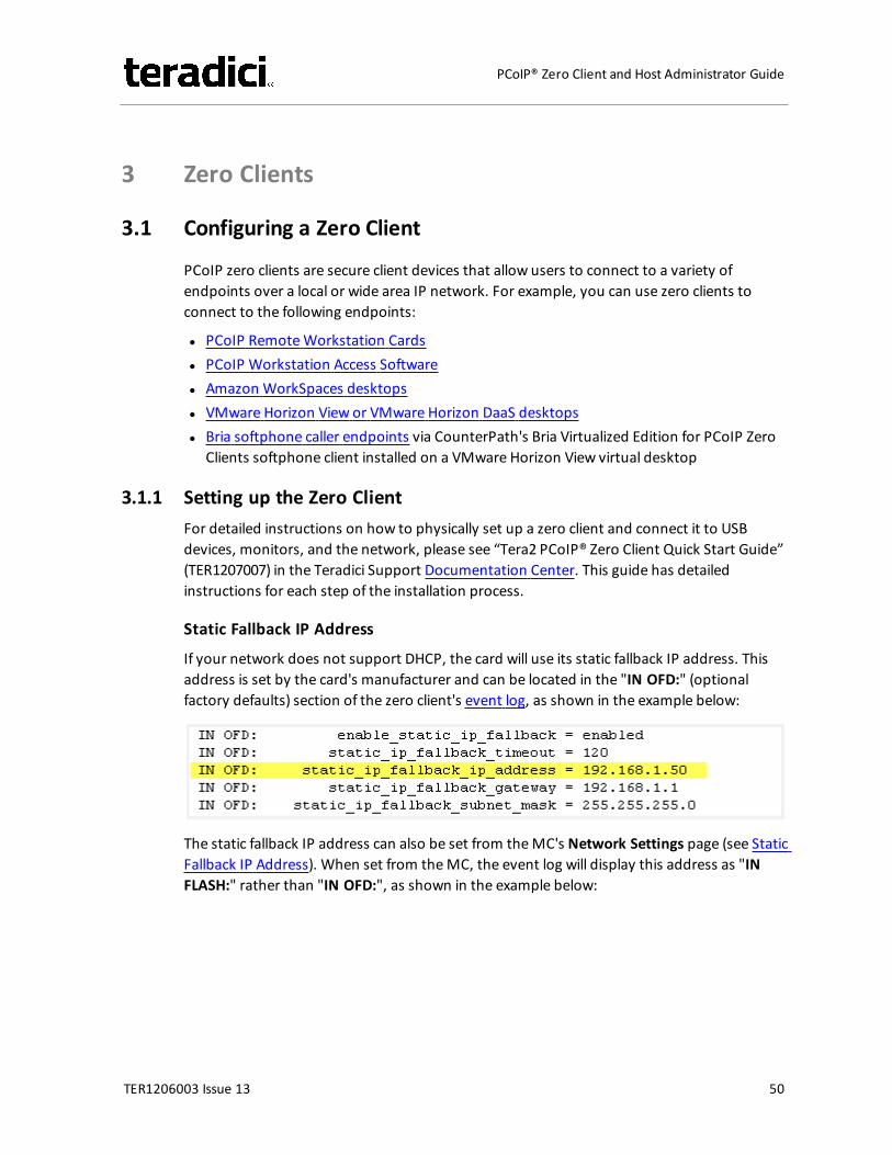
3 Zero Clients
3.1 Configuring a Zero Client
PCoIP zero clients are secure client devices that allow users to connect to a variety ofendpoints over a local or wide area IP network. For example, you can use zero clients toconnect to the following endpoints:
l PCoIP RemoteWorkstation Cardsl PCoIP Workstation Access Softwarel Amazon WorkSpaces desktopsl VMware Horizon View or VMware Horizon DaaS desktopsl Bria softphone caller endpoints via CounterPath's Bria Virtualized Edition for PCoIP Zero
Clients softphone client installed on a VMware Horizon View virtual desktop
3.1.1 Setting up the Zero ClientFor detailed instructions on how to physically set up a zero client and connect it to USBdevices, monitors, and the network, please see “Tera2 PCoIP® Zero Client Quick Start Guide”(TER1207007) in the Teradici Support Documentation Center. This guide has detailedinstructions for each step of the installation process.
Static Fallback IP Address
If your network does not support DHCP, the card will use its static fallback IP address. Thisaddress is set by the card's manufacturer and can be located in the "IN OFD:" (optionalfactory defaults) section of the zero client's event log, as shown in the example below:
The static fallback IP address can also be set from theMC's Network Settings page (see StaticFallback IP Address). When set from theMC, the event log will display this address as "INFLASH:" rather than "IN OFD:", as shown in the example below:
TER1206003 Issue 13 50
PCoIP® Zero Client and Host Administrator Guide
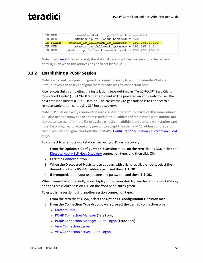
Note: If you reset the zero client, the static fallback IP address will revert to the factorydefault, even when this address has been set by theMC.
3.1.2 Establishing a PCoIP SessionNote: Zero clients are pre-configured to connect directly to a PCoIP RemoteWorkstationCard, but you can easily configure them for any session connection type.
After successfully completing the installation steps outlined in “Tera2 PCoIP® Zero ClientQuick Start Guide” (TER1207007), the zero client will be powered on and ready to use. Thenext step is to initiate a PCoIP session. The easiest way to get started is to connect to aremote workstation card using SLP host discovery.
Note: SLP host discovery requires the zero client and host PC to reside on the same subnet.You also need to know the IP address and/or MAC address of the remote workstation cardso you can select it from the list of available hosts. In addition, the remote workstation cardmust be configured to accept any peer or to accept the specific MAC address of the zeroclient. You can configure this from the host AWI Configuration > Session > Direct from Clientpage.
To connect to a remote workstation card using SLP host discovery:
1. From theOptions > Configuration > Sessionmenu on the zero client's OSD, select theDirect to Host + SLP Host Discovery connection type, and then click OK.
2. Click the Connect button.3. When theDiscovered Hosts screen appears with a list of available hosts, select the
desired one by its IP/MAC address pair, and then click OK.4. If prompted, enter your user name and password, and then click OK.
When connected successfully, your display shows your desktop on the remote workstation,and the zero client's session LED on the front panel turns green.
To establish a session using another session connection type:
1. From the zero client's OSD, select theOptions > Configuration > Sessionmenu.2. From the Connection Type drop-down list, select the desired connection type:
l Direct to Hostl PCoIP Connection Manager (Tera2 only)l PCoIP Connection Manager + Auto-Logon (Tera2 only)l View Connection Serverl View Connection Server + Auto-Logon
TER1206003 Issue 13 51
PCoIP® Zero Client and Host Administrator Guide
l View Connection Server + Kioskl View Connection Server + Imprivata OneSignl Connection Management Interface
3. After entering the required information, click OK on the Session page.4. Click the Connect button.5. If prompted, enter your user name and password.6. If you are using a brokered connection and havemore than one entitlement, select the
desired one, and then click Connect.
When connected successfully, your display shows your desktop on the remote workstation,and the zero client's session LED on the front panel turns green.
3.1.3 Other Useful LinksThe following topics providemore information about connecting zero clients and remoteworkstation cards.
l PCoIP Endpoints: Gives an overview of the PCoIP clients and hosts you can deploy inyour network.
l Connection Prerequisites: Explains the conditions that must be in place beforeconnecting PCoIP clients and hosts.
l Common LAN Scenarios: Provides a quick overview of how to connect PCoIP clients andhosts from within a LAN.l Zero Client to RemoteWorkstation Card (LAN)l Zero Client to RemoteWorkstation Card via View Connection Server (LAN)l Zero Client to Virtual Desktop via View Connection Server (LAN)
l Common Remote Access Scenarios: Provides a quick overview of how to connect PCoIPclients and hosts remotely.l Zero Client to RemoteWorkstation Card (WAN)l Zero Client to RemoteWorkstation Card via Hardware VPN (WAN)l Zero Client to RemoteWorkstation Card via 3rd Party Broker (WAN)l Zero Client to RemoteWorkstation Card via View Security Server (WAN)l Zero Client to Virtual Desktop via View Security Server (WAN)
TER1206003 Issue 13 52
PCoIP® Zero Client and Host Administrator Guide
4 Remote Workstation Cards
4.1 Configuring a Remote Workstation Card
Teradici's PCoIP RemoteWorkstation Card is a small add-in card that can be integrated intotower workstations, rack mount workstations, computer blades, and server blades. Thecard's TERA-series processor performs advanced display compression algorithms to encode auser's full workstation environment. This information is then communicated in real time overan IP network to the user's PCoIP client.
4.1.1 Installing a Remote Workstation CardImportant! The remote workstation's card's MAC address is located on a sticker on the card.It is important to write down this address before installing the card in the workstation. seeKB 15134-1348 in the Teradici Support Site for additional information.
For detailed instructions on how to physically install the card, please see “PCoIP® RemoteWorkstation Card Quick Start Guide” (TER1207006) in the Teradici Support DocumentationCenter. This guide has detailed instructions for each step of the installation process.
Important: When connecting the graphics card to the remote workstation card with theprovided cables, always connect the lowest numbered connector on the graphics card to thelowest numbered connector on the remote workstation card, and continue upward.
Some graphics cards have both DVI and DisplayPort connectors. To support 2560x1600resolution when connecting these graphics cards, connect the lowest numbered DisplayPortconnector on the graphics card to the lowest number connector on the remote workstationcard. Connecting the DVI connector on the graphics card to the remote workstation card willlimit you to 1920x1200.
For complete details about the resolutions supported by different connectors and cables,see KB 15134-1607 in the Teradici Support Site.
4.1.2 Establishing a PCoIP Session to a Remote Workstation Card from aZero ClientNote: For information on how to connect using a Teradici PCoIP® Software Client, see“Teradici PCoIP® Software Clients User Guide” (TER1307002) in the Teradici SupportDocumentation Center.
After successfully completing the installation steps outlined in “PCoIP® RemoteWorkstationCard Quick Start Guide” (TER1207006), the card will be connected to the network and theworkstation powered on. The next step is to initiate a PCoIP session from a zero client usingSLP host discovery.
TER1206003 Issue 13 53
PCoIP® Zero Client and Host Administrator Guide
Note: SLP host discovery requires the zero client and host PC to reside on the same subnet.You also need to know the IP address and/or MAC address of the remote workstation cardso you can select it from the list of available hosts. In addition, the remote workstation cardmust be configured to accept any peer or to accept the specific MAC address of the zeroclient. You can configure this from the host AWI Configuration > Session > Direct from Clientpage.
By default, DHCP is enabled on the remote workstation card to allow your DHCP server toassign an IP address. If your network does not support DHCP, the card's default IP addresswill be 192.168.1.100.
To connect to a remote workstation card using SLP host discovery:
1. From theOptions > Configuration > Sessionmenu on the zero client's OSD, select theDirect to Host + SLP Host Discovery connection type, and then click OK.
2. Click the Connect button.3. When theDiscovered Hosts screen appears with a list of available hosts, select the
desired one by its IP/MAC address pair, and then click OK.4. If prompted, enter your user name and password, and then click OK.
When connected successfully, your display shows your desktop on the remote workstation,and the zero client's session LED on the front panel turns green.
4.1.3 Installing the PCoIP Host SoftwareOptionally, you can also install the PCoIP host software package on the workstation to allowyou to manage the card directly from the PCoIP host software UI on the workstation.
Note: Before installing this package on the workstation, you must first log in to the remoteworkstation card from the AWI, and enable the host driver function in the firmware from theConfiguration > Host Driver Functionmenu.
For detailed instructions on how to install the PCoIP host software, please see “PCoIP® HostSoftware for Windows User Guide” (TER1008001) or “PCoIP® Host Software for Linux UserGuide” (TER1104006) in the Teradici Support Documentation Center.
4.1.4 Other Useful LinksThe following topics providemore information about connecting zero clients and remoteworkstation cards.
l PCoIP Endpoints: Gives an overview of the PCoIP clients and hosts you can deploy inyour network.
l Connection Prerequisites: Explains the conditions that must be in place beforeconnecting PCoIP clients and hosts.
l Common LAN Scenarios: Provides a quick overview of how to connect PCoIP clients andhosts from within a LAN.
TER1206003 Issue 13 54
PCoIP® Zero Client and Host Administrator Guide
l Zero Client to RemoteWorkstation Card (LAN)l Zero Client to RemoteWorkstation Card via View Connection Server (LAN)l Zero Client to Virtual Desktop via View Connection Server (LAN)
l Common Remote Access Scenarios: Provides a quick overview of how to connect PCoIPclients and hosts remotely.l Zero Client to RemoteWorkstation Card (WAN)l Zero Client to RemoteWorkstation Card via Hardware VPN (WAN)l Zero Client to RemoteWorkstation Card via 3rd Party Broker (WAN)l Zero Client to RemoteWorkstation Card via View Security Server (WAN)l Zero Client to Virtual Desktop via View Security Server (WAN)
TER1206003 Issue 13 55
PCoIP® Zero Client and Host Administrator Guide

5 PCoIP Management Tools
5.1 PCoIP Management Console
5.1.1 About the MCThe PCoIP Management Console (MC) lets you centrally manage the devices in your PCoIPdeployment. It is packaged as a VMware® virtual machine (VM), running on VMware Player.You can use theMC to view status information for devices, create groups and profiles,configure a profile (a collection of configuration settings) that you can apply to a group (oneor more devices that require the same configuration), upload certificates and firmware todevices, control the power settings for devices, manage themonitoring of device event logs,and much more.
TheMC topics in this help system describe how to use theMC to configure a device profile.For complete information about how to install, set up, and use theMC, please refer to“Teradici PCoIP®Management Console User Manual” (TER0812002) in the Teradici SupportDocumentation Center.
After you type the IP address of theMC web interface into an Internet Explorer or MozillaFirefox browser, the browser will use HTTPS (HTTP over an SSL socket) to connect to theMCweb interface. The IP address for theMC web interface is configured (either statically or viaDHCP) from theMC virtual machine console after installation. Access to theMC is controlledusing an administrative password, which is also set from theMC virtual machine consoleafter installation. Full details about these setup procedures are included in the “TeradiciPCoIP®Management Console User Manual” (TER0812002).
TheMC's HTTPS connection is secured using a PCoIP MC root Certificate Authority (CA) certificate. For information on how to install this certificate, see “Teradici PCoIP®Management Console User Manual” (TER0812002).
TheMC is compatible with the following browsers:
l Firefox version 23 or newerl Internet Explorer 8 and 9l Internet Explorer 11 in compatibility view
5.1.2 Logging into the MCTo log into theManagement Console web interface:
1. From an Internet browser, enter the IP address of theMC web page. The IP addressmay be a static or dynamic address, depending on how it is determined when theMC isconfigured:
TER1206003 Issue 13 56
PCoIP® Zero Client and Host Administrator Guide
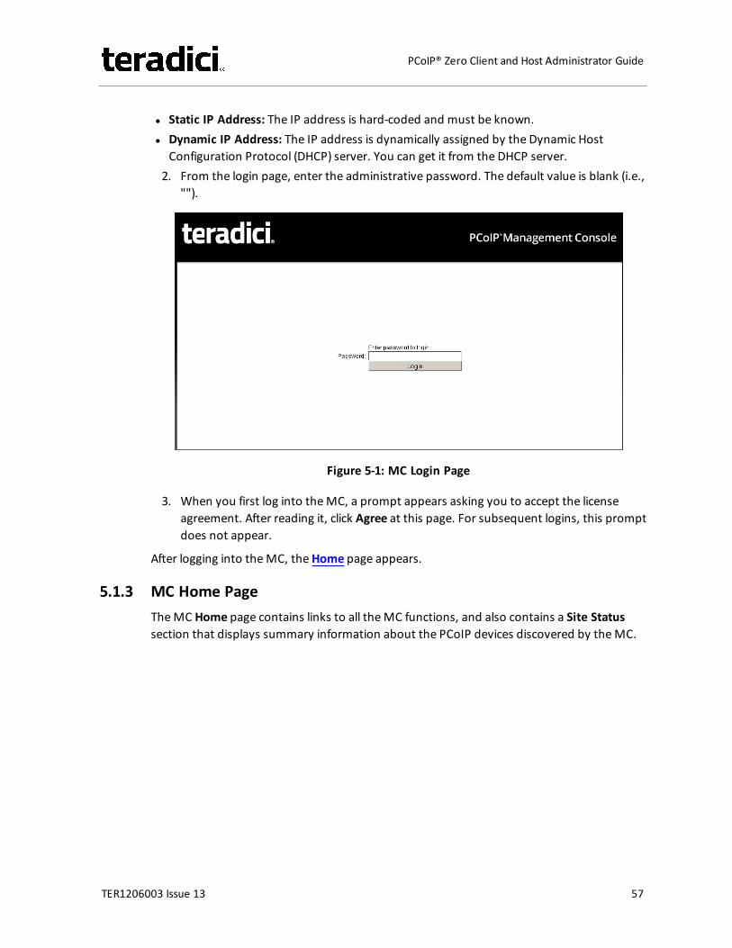
l Static IP Address: The IP address is hard-coded and must be known.l Dynamic IP Address: The IP address is dynamically assigned by the Dynamic Host
Configuration Protocol (DHCP) server. You can get it from the DHCP server.2. From the login page, enter the administrative password. The default value is blank (i.e.,
"").
Figure 5-1: MC Login Page
3. When you first log into theMC, a prompt appears asking you to accept the licenseagreement. After reading it, click Agree at this page. For subsequent logins, this promptdoes not appear.
After logging into theMC, theHome page appears.
5.1.3 MC Home PageTheMC Home page contains links to all theMC functions, and also contains a Site Statussection that displays summary information about the PCoIP devices discovered by theMC.
TER1206003 Issue 13 57
PCoIP® Zero Client and Host Administrator Guide
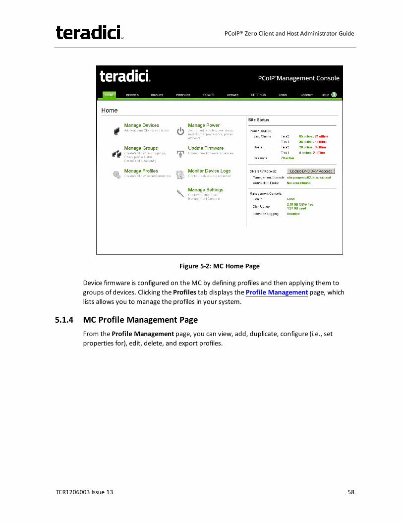
Figure 5-2: MC Home Page
Device firmware is configured on theMC by defining profiles and then applying them togroups of devices. Clicking the Profiles tab displays the Profile Management page, whichlists allows you to manage the profiles in your system.
5.1.4 MC Profile Management PageFrom the Profile Management page, you can view, add, duplicate, configure (i.e., setproperties for), edit, delete, and export profiles.
TER1206003 Issue 13 58
PCoIP® Zero Client and Host Administrator Guide
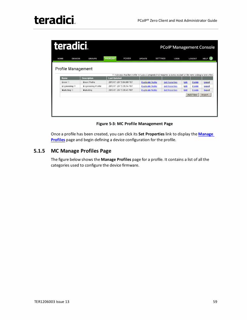
Figure 5-3: MC Profile Management Page
Once a profile has been created, you can click its Set Properties link to display theManageProfiles page and begin defining a device configuration for the profile.
5.1.5 MC Manage Profiles PageThe figure below shows theManage Profiles page for a profile. It contains a list of all thecategories used to configure the device firmware.
TER1206003 Issue 13 59
PCoIP® Zero Client and Host Administrator Guide
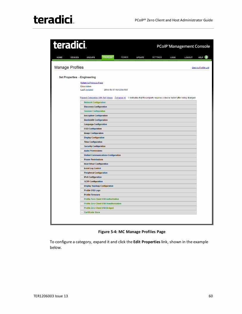
Figure 5-4: MC Manage Profiles Page
To configure a category, expand it and click the Edit Properties link, shown in the examplebelow.
TER1206003 Issue 13 60
PCoIP® Zero Client and Host Administrator Guide
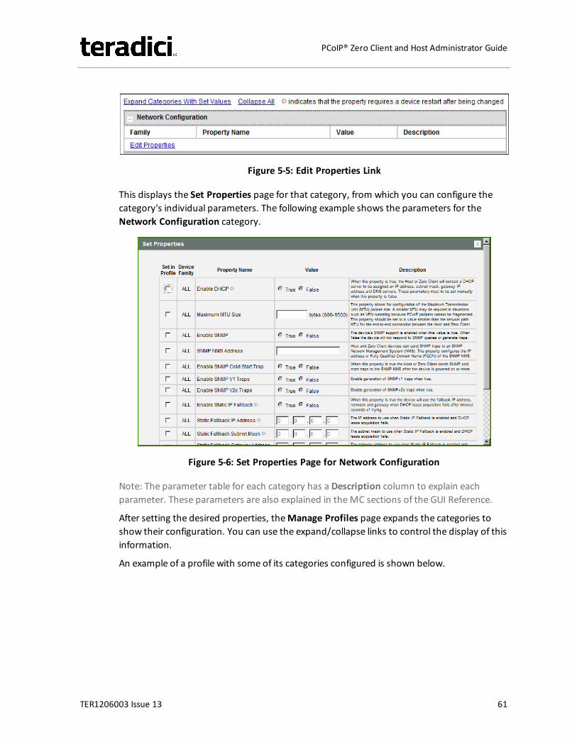
Figure 5-5: Edit Properties Link
This displays the Set Properties page for that category, from which you can configure thecategory's individual parameters. The following example shows the parameters for theNetwork Configuration category.
Figure 5-6: Set Properties Page for Network Configuration
Note: The parameter table for each category has a Description column to explain eachparameter. These parameters are also explained in theMC sections of the GUI Reference.
After setting the desired properties, theManage Profiles page expands the categories toshow their configuration. You can use the expand/collapse links to control the display of thisinformation.
An example of a profile with some of its categories configured is shown below.
TER1206003 Issue 13 61
PCoIP® Zero Client and Host Administrator Guide
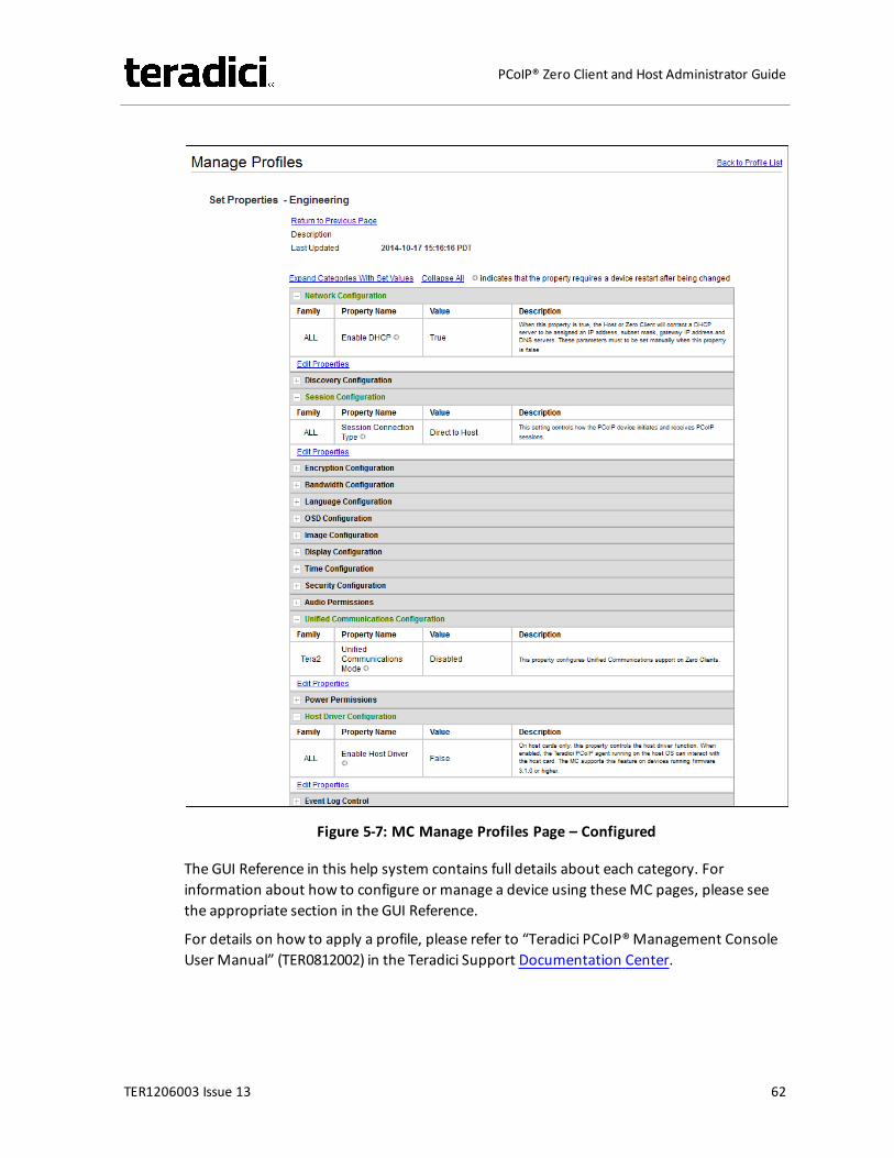
Figure 5-7: MC Manage Profiles Page – Configured
The GUI Reference in this help system contains full details about each category. Forinformation about how to configure or manage a device using theseMC pages, please seethe appropriate section in the GUI Reference.
For details on how to apply a profile, please refer to “Teradici PCoIP®Management ConsoleUser Manual” (TER0812002) in the Teradici Support Documentation Center.
TER1206003 Issue 13 62
PCoIP® Zero Client and Host Administrator Guide
5.2 PCoIP Administrative Web Interface
5.2.1 About the AWIThe PCoIP AdministrativeWeb Interface (AWI) allows you to interact remotely with a PCoIPhost or client. From the AWI, you can manage and configure a host or client, view importantinformation about it, and even upload firmware and certificates to it.
After you type the device's IP address into an Internet Explorer or Mozilla Firefox browser,the browser will use HTTPS (HTTP over an SSL socket) to connect to the device's AWI webpage. Access to the AWI is controlled using an administrative password, which can beoptionally disabled.
The AWI's HTTPS connection is secured using a PCoIP root Certificate Authority (CA) certificate. To avoid warning messages when you log into the AWI, it is recommended thatyou install this certificate in your browser. The certificate file ("cacert.pem") is alwaysincluded in a firmware release, but you can also download it directly from KB 15134-529 inthe Teradici Support Site. Detailed instructions on how to install the certificate are alsoincluded in this KB.
The following browsers are supported in this release:
l Firefox versions 26 (or newer)l Internet Explorer 7 and 8l Internet Explorer 11 in compatibility view
5.2.2 Logging into the AWITo log into the Administrator Web Interface web page for a host or client:
1. From an Internet browser, enter the IP address of the host or client. The IP addressmay be a static or dynamic address, depending on how the IP addresses aredetermined within your IP network:l Static IP Address: The IP address is hard-coded and must be known.l Dynamic IP Address: The IP address is dynamically assigned by the Dynamic Host
Configuration Protocol (DHCP) server. You can get it from the DHCP server.2. From the Log In page, enter the administrative password. The default value is blank
(i.e., "").
TER1206003 Issue 13 63
PCoIP® Zero Client and Host Administrator Guide
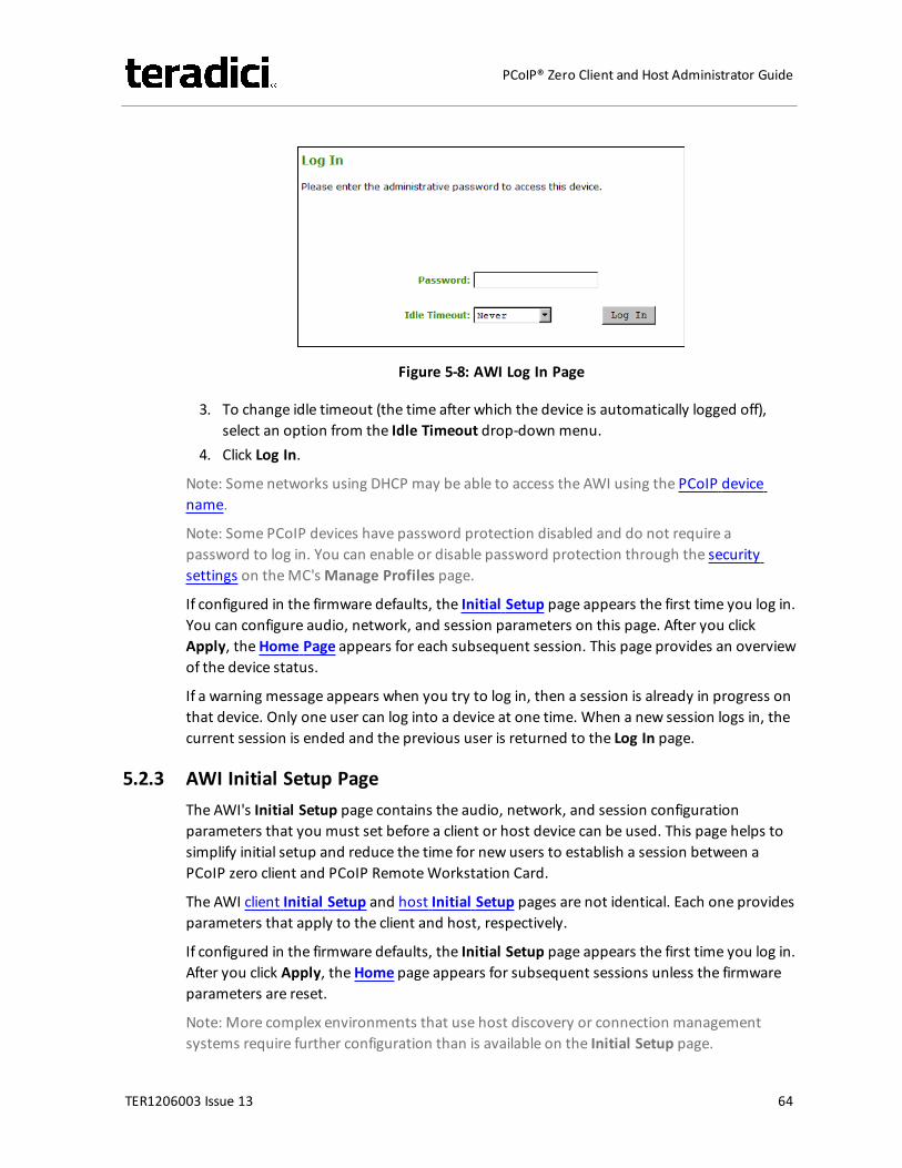
Figure 5-8: AWI Log In Page
3. To change idle timeout (the time after which the device is automatically logged off),select an option from the Idle Timeout drop-down menu.
4. Click Log In.
Note: Some networks using DHCP may be able to access the AWI using the PCoIP devicename.
Note: Some PCoIP devices have password protection disabled and do not require apassword to log in. You can enable or disable password protection through the securitysettings on theMC'sManage Profiles page.
If configured in the firmware defaults, the Initial Setup page appears the first time you log in.You can configure audio, network, and session parameters on this page. After you clickApply, theHome Page appears for each subsequent session. This page provides an overviewof the device status.
If a warning message appears when you try to log in, then a session is already in progress onthat device. Only one user can log into a device at one time. When a new session logs in, thecurrent session is ended and the previous user is returned to the Log In page.
5.2.3 AWI Initial Setup PageThe AWI's Initial Setup page contains the audio, network, and session configurationparameters that you must set before a client or host device can be used. This page helps tosimplify initial setup and reduce the time for new users to establish a session between aPCoIP zero client and PCoIP RemoteWorkstation Card.
The AWI client Initial Setup and host Initial Setup pages are not identical. Each one providesparameters that apply to the client and host, respectively.
If configured in the firmware defaults, the Initial Setup page appears the first time you log in.After you click Apply, theHome page appears for subsequent sessions unless the firmwareparameters are reset.
Note: More complex environments that use host discovery or connection managementsystems require further configuration than is available on the Initial Setup page.
TER1206003 Issue 13 64
PCoIP® Zero Client and Host Administrator Guide
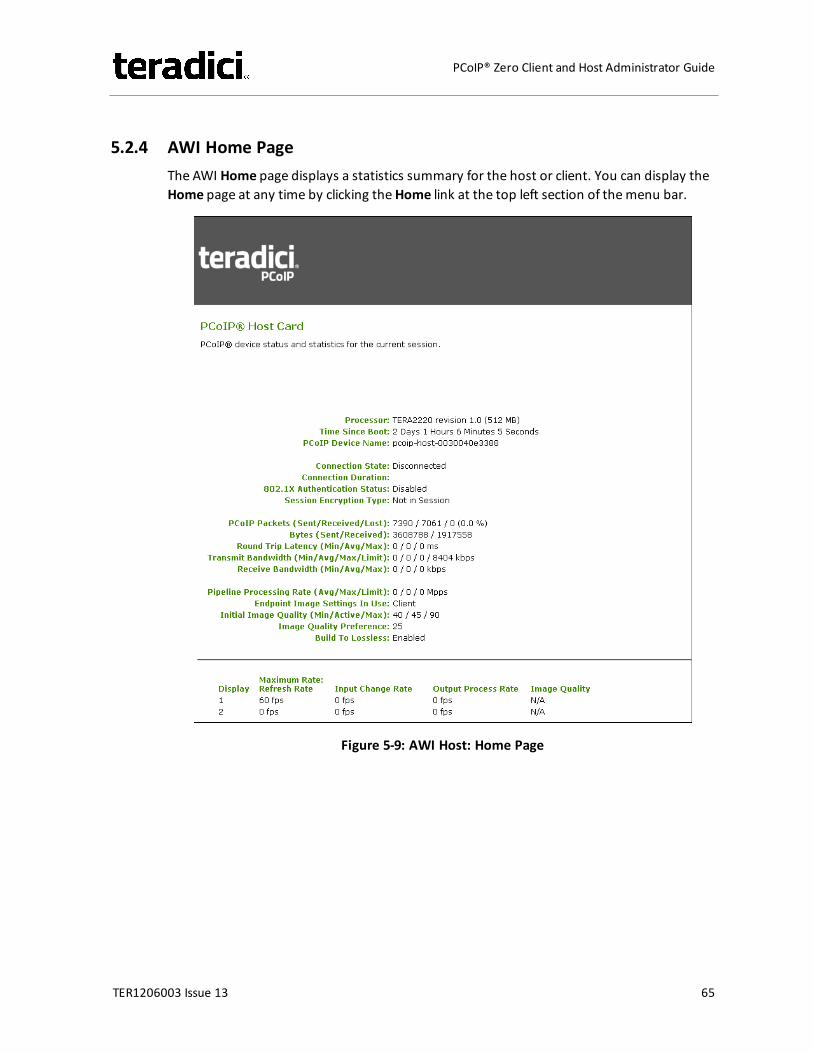
5.2.4 AWI Home PageThe AWI Home page displays a statistics summary for the host or client. You can display theHome page at any time by clicking theHome link at the top left section of themenu bar.
Figure 5-9: AWI Host: Home Page
TER1206003 Issue 13 65
PCoIP® Zero Client and Host Administrator Guide
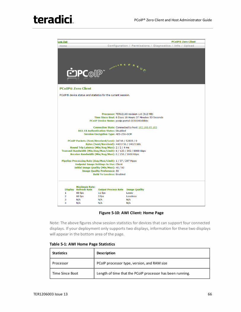
Figure 5-10: AWI Client: Home Page
Note: The above figures show session statistics for devices that can support four connecteddisplays. If your deployment only supports two displays, information for these two displayswill appear in the bottom area of the page.
Table 5-1: AWI Home Page Statistics
Statistics Description
Processor PCoIP processor type, version, and RAM size
Time Since Boot Length of time that the PCoIP processor has been running.
TER1206003 Issue 13 66
PCoIP® Zero Client and Host Administrator Guide
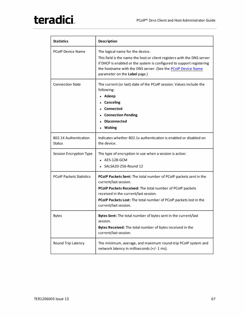
Statistics Description
PCoIP Device Name The logical name for the device.This field is the name the host or client registers with the DNS serverif DHCP is enabled or the system is configured to support registeringthe hostname with the DNS server. (See the PCoIP Device Nameparameter on the Label page.)
Connection State The current (or last) state of the PCoIP session. Values include thefollowing:l Asleepl Cancelingl Connectedl Connection Pendingl Disconnectedl Waking
802.1X AuthenticationStatus
Indicates whether 802.1x authentication is enabled or disabled onthe device.
Session Encryption Type The type of encryption in use when a session is active:l AES-128-GCMl SALSA20-256-Round 12
PCoIP Packets Statistics PCoIP Packets Sent: The total number of PCoIP packets sent in thecurrent/last session.PCoIP Packets Received: The total number of PCoIP packetsreceived in the current/last session.PCoIP Packets Lost: The total number of PCoIP packets lost in thecurrent/last session.
Bytes Bytes Sent: The total number of bytes sent in the current/lastsession.Bytes Received: The total number of bytes received in thecurrent/last session.
Round Trip Latency The minimum, average, and maximum round-trip PCoIP system andnetwork latency in milliseconds (+/- 1 ms).
TER1206003 Issue 13 67
PCoIP® Zero Client and Host Administrator Guide

Statistics Description
Bandwidth Statistics Transmit Bandwidth: The minimum, average, and maximum traffictransmitted by the Tera processor. The active bandwidth limit is themaximum amount of network traffic the Tera processor maycurrently generate. The value is derived from the configuredbandwidth parameters and the current (or last) network congestionlevels.Receive Bandwidth: The minimum, average, and maximum trafficreceived by the Tera processor.
Pipeline Processing Rate How much image data is currently being processed by the imageengine (in megapixels per second).
Endpoint Image SettingsIn Use
Displays if the image settings being used are configured within theclient or within the host. This is based on how the Use Client ImageSettings field is configured on the Image page for the host device.
Image Quality The minimum and maximum quality setting is taken from the Imagepage for the device.The active setting is what’s currently being used in the session andonly appears on the host.
Image QualityPreference
This setting is taken from the Image Quality Preference field on theImage page. The value determines if the image is set to a smootherversus a sharper image.
Build to Lossless Options that may appear in this field include the following:Enabled: The Disable Build to Lossless field on the Image page isunchecked.Disabled: The Disable Build to Lossless field is checked.
Display The port number for the display.
Maximum Rate This column shows the refresh rate of the attached display.If the Maximum Rate field on the Image page is set to 0 (i.e., there isno limit), the maximum rate is taken from the monitor's refresh rate.If the Maximum Rate field on the Image page is set to a valuegreater than 0, the refresh rate shows as "User Defined."
TER1206003 Issue 13 68
PCoIP® Zero Client and Host Administrator Guide
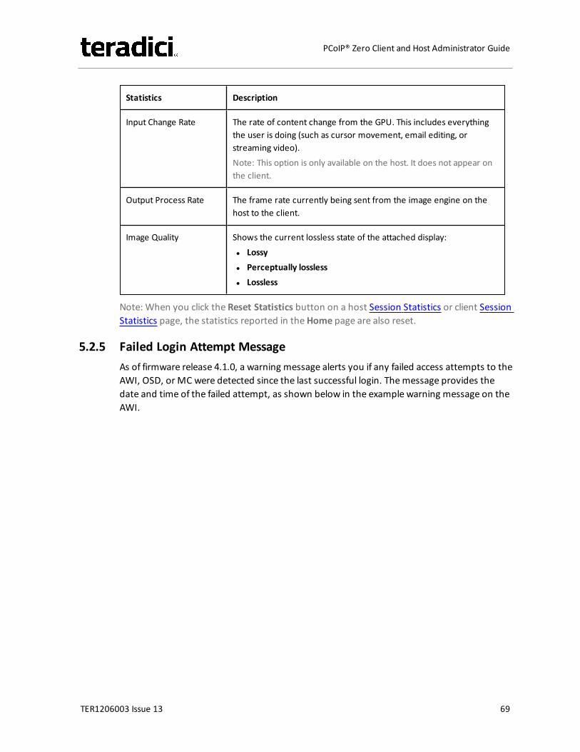
Statistics Description
Input Change Rate The rate of content change from the GPU. This includes everythingthe user is doing (such as cursor movement, email editing, orstreaming video).Note: This option is only available on the host. It does not appear onthe client.
Output Process Rate The frame rate currently being sent from the image engine on thehost to the client.
Image Quality Shows the current lossless state of the attached display:l Lossyl Perceptually losslessl Lossless
Note: When you click the Reset Statistics button on a host Session Statistics or client SessionStatistics page, the statistics reported in theHome page are also reset.
5.2.5 Failed Login Attempt MessageAs of firmware release 4.1.0, a warning message alerts you if any failed access attempts to theAWI, OSD, or MC were detected since the last successful login. Themessage provides thedate and time of the failed attempt, as shown below in the example warning message on theAWI.
TER1206003 Issue 13 69
PCoIP® Zero Client and Host Administrator Guide
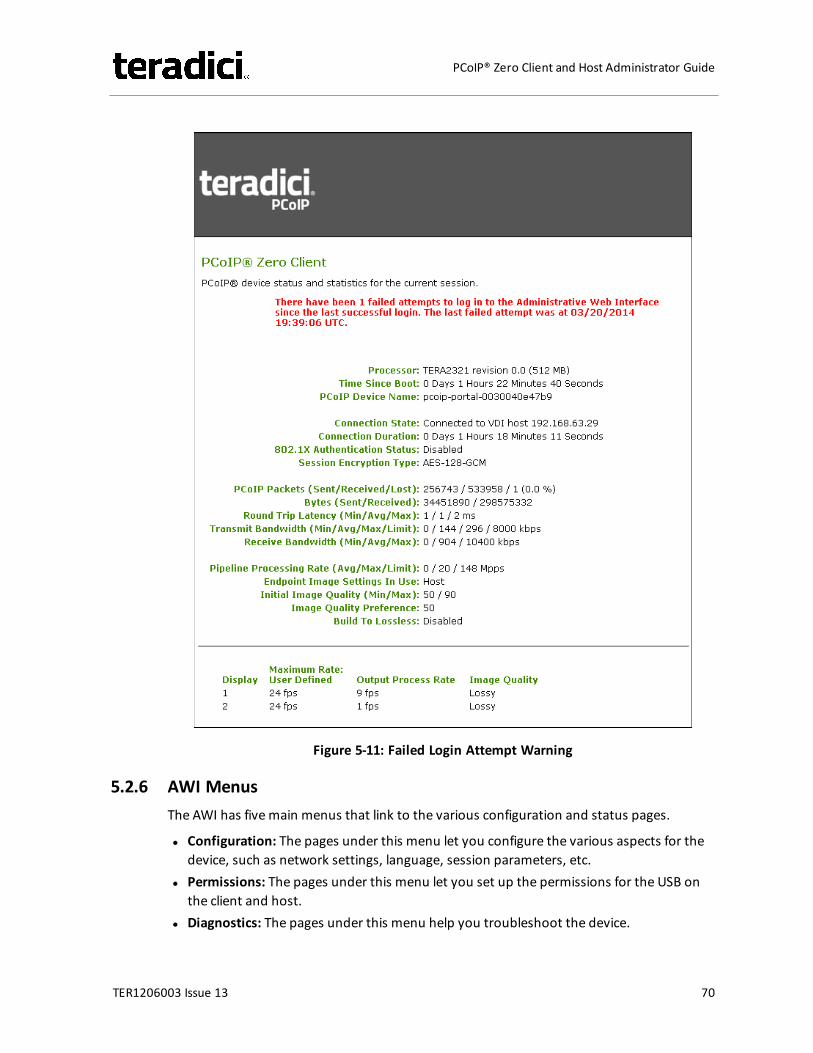
Figure 5-11: Failed Login Attempt Warning
5.2.6 AWI MenusThe AWI has fivemain menus that link to the various configuration and status pages.
l Configuration: The pages under this menu let you configure the various aspects for thedevice, such as network settings, language, session parameters, etc.
l Permissions: The pages under this menu let you set up the permissions for the USB onthe client and host.
l Diagnostics: The pages under this menu help you troubleshoot the device.
TER1206003 Issue 13 70
PCoIP® Zero Client and Host Administrator Guide
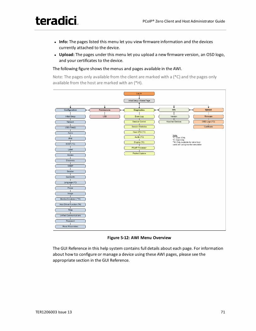
l Info: The pages listed this menu let you view firmware information and the devicescurrently attached to the device.
l Upload: The pages under this menu let you upload a new firmware version, an OSD logo,and your certificates to the device.
The following figure shows themenus and pages available in the AWI.
Note: The pages only available from the client aremarked with a (*C) and the pages onlyavailable from the host aremarked with an (*H).
Figure 5-12: AWI Menu Overview
The GUI Reference in this help system contains full details about each page. For informationabout how to configure or manage a device using these AWI pages, please see theappropriate section in the GUI Reference.
TER1206003 Issue 13 71
PCoIP® Zero Client and Host Administrator Guide
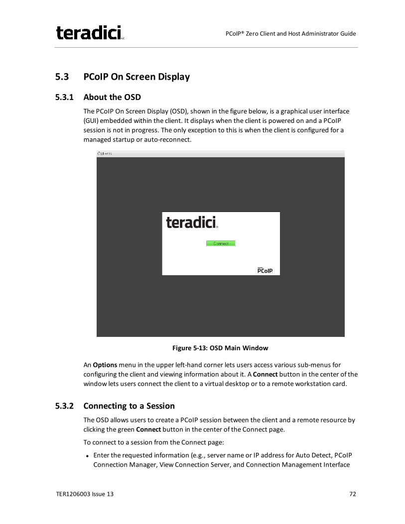
5.3 PCoIP On Screen Display
5.3.1 About the OSDThe PCoIP On Screen Display (OSD), shown in the figure below, is a graphical user interface(GUI) embedded within the client. It displays when the client is powered on and a PCoIPsession is not in progress. The only exception to this is when the client is configured for amanaged startup or auto-reconnect.
Figure 5-13: OSD Main Window
An Optionsmenu in the upper left-hand corner lets users access various sub-menus forconfiguring the client and viewing information about it. A Connect button in the center of thewindow lets users connect the client to a virtual desktop or to a remote workstation card.
5.3.2 Connecting to a SessionThe OSD allows users to create a PCoIP session between the client and a remote resource byclicking the green Connect button in the center of the Connect page.
To connect to a session from the Connect page:
l Enter the requested information (e.g., server name or IP address for Auto Detect, PCoIPConnection Manager, View Connection Server, and Connection Management Interface
TER1206003 Issue 13 72
PCoIP® Zero Client and Host Administrator Guide
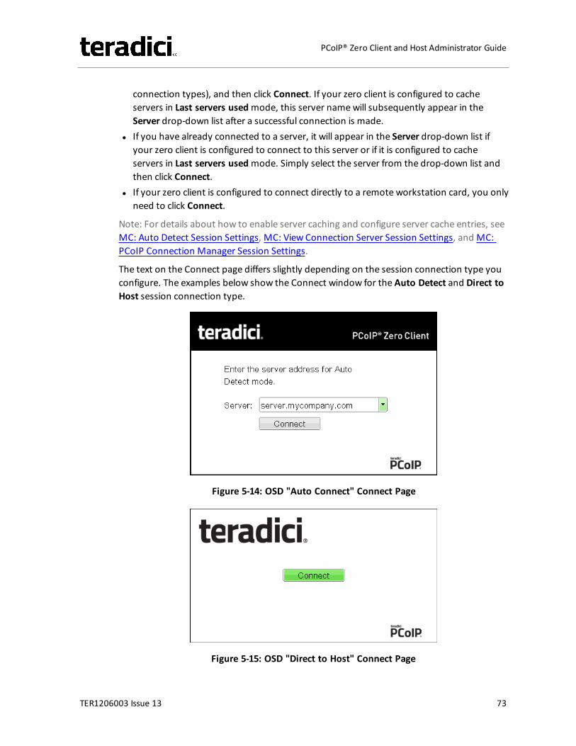
connection types), and then click Connect. If your zero client is configured to cacheservers in Last servers usedmode, this server namewill subsequently appear in theServer drop-down list after a successful connection is made.
l If you have already connected to a server, it will appear in the Server drop-down list ifyour zero client is configured to connect to this server or if it is configured to cacheservers in Last servers usedmode. Simply select the server from the drop-down list andthen click Connect.
l If your zero client is configured to connect directly to a remote workstation card, you onlyneed to click Connect.
Note: For details about how to enable server caching and configure server cache entries, seeMC: Auto Detect Session Settings, MC: View Connection Server Session Settings, and MC:PCoIP Connection Manager Session Settings.
The text on the Connect page differs slightly depending on the session connection type youconfigure. The examples below show the Connect window for the Auto Detect and Direct toHost session connection type.
Figure 5-14: OSD "Auto Connect" Connect Page
Figure 5-15: OSD "Direct to Host" Connect Page
TER1206003 Issue 13 73
PCoIP® Zero Client and Host Administrator Guide
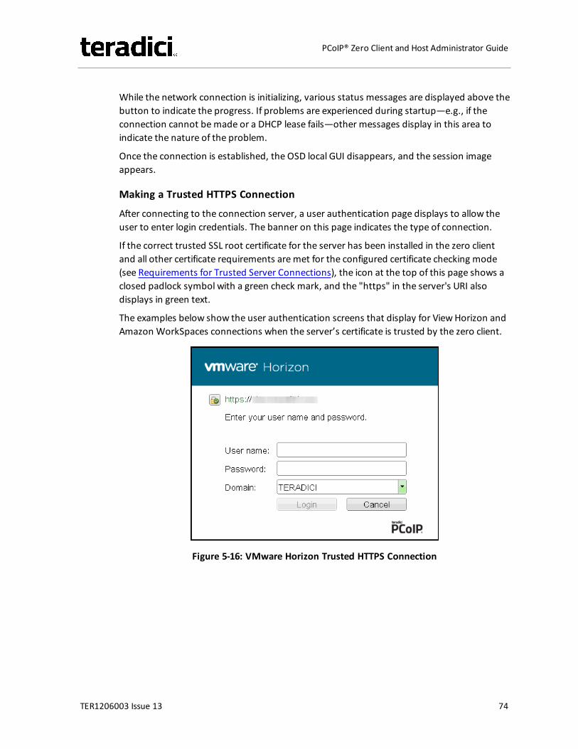
While the network connection is initializing, various status messages are displayed above thebutton to indicate the progress. If problems are experienced during startup—e.g., if theconnection cannot bemade or a DHCP lease fails—other messages display in this area toindicate the nature of the problem.
Once the connection is established, the OSD local GUI disappears, and the session imageappears.
Making a Trusted HTTPS Connection
After connecting to the connection server, a user authentication page displays to allow theuser to enter login credentials. The banner on this page indicates the type of connection.
If the correct trusted SSL root certificate for the server has been installed in the zero clientand all other certificate requirements aremet for the configured certificate checking mode(see Requirements for Trusted Server Connections), the icon at the top of this page shows aclosed padlock symbol with a green check mark, and the "https" in the server's URI alsodisplays in green text.
The examples below show the user authentication screens that display for ViewHorizon andAmazon WorkSpaces connections when the server’s certificate is trusted by the zero client.
Figure 5-16: VMware Horizon Trusted HTTPS Connection
TER1206003 Issue 13 74
PCoIP® Zero Client and Host Administrator Guide
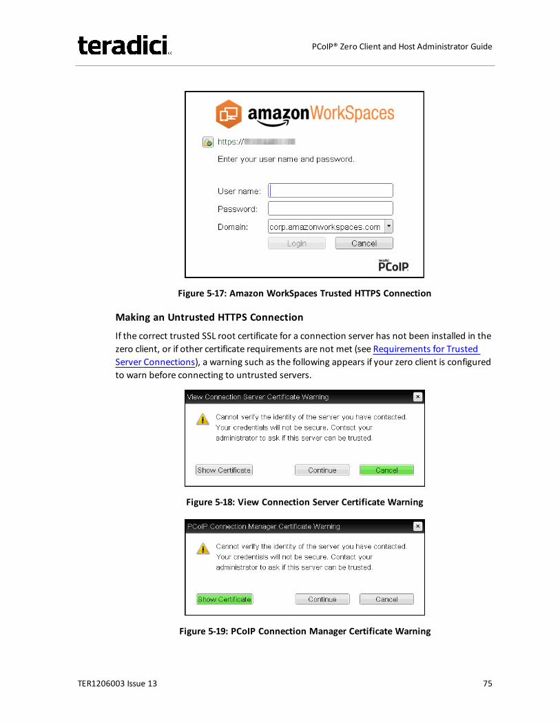
Figure 5-17: Amazon WorkSpaces Trusted HTTPS Connection
Making an Untrusted HTTPS Connection
If the correct trusted SSL root certificate for a connection server has not been installed in thezero client, or if other certificate requirements are not met (see Requirements for TrustedServer Connections), a warning such as the following appears if your zero client is configuredto warn before connecting to untrusted servers.
Figure 5-18: View Connection Server Certificate Warning
Figure 5-19: PCoIP Connection Manager Certificate Warning
TER1206003 Issue 13 75
PCoIP® Zero Client and Host Administrator Guide
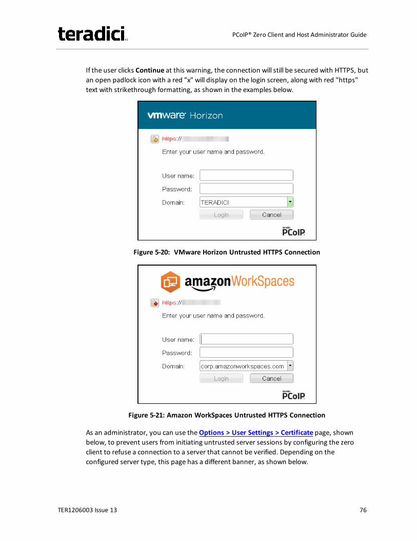
If the user clicks Continue at this warning, the connection will still be secured with HTTPS, butan open padlock icon with a red "x" will display on the login screen, along with red "https"text with strikethrough formatting, as shown in the examples below.
Figure 5-20: VMware Horizon Untrusted HTTPS Connection
Figure 5-21: Amazon WorkSpaces Untrusted HTTPS Connection
As an administrator, you can use theOptions > User Settings > Certificate page, shownbelow, to prevent users from initiating untrusted server sessions by configuring the zeroclient to refuse a connection to a server that cannot be verified. Depending on theconfigured server type, this page has a different banner, as shown below.
TER1206003 Issue 13 76
PCoIP® Zero Client and Host Administrator Guide
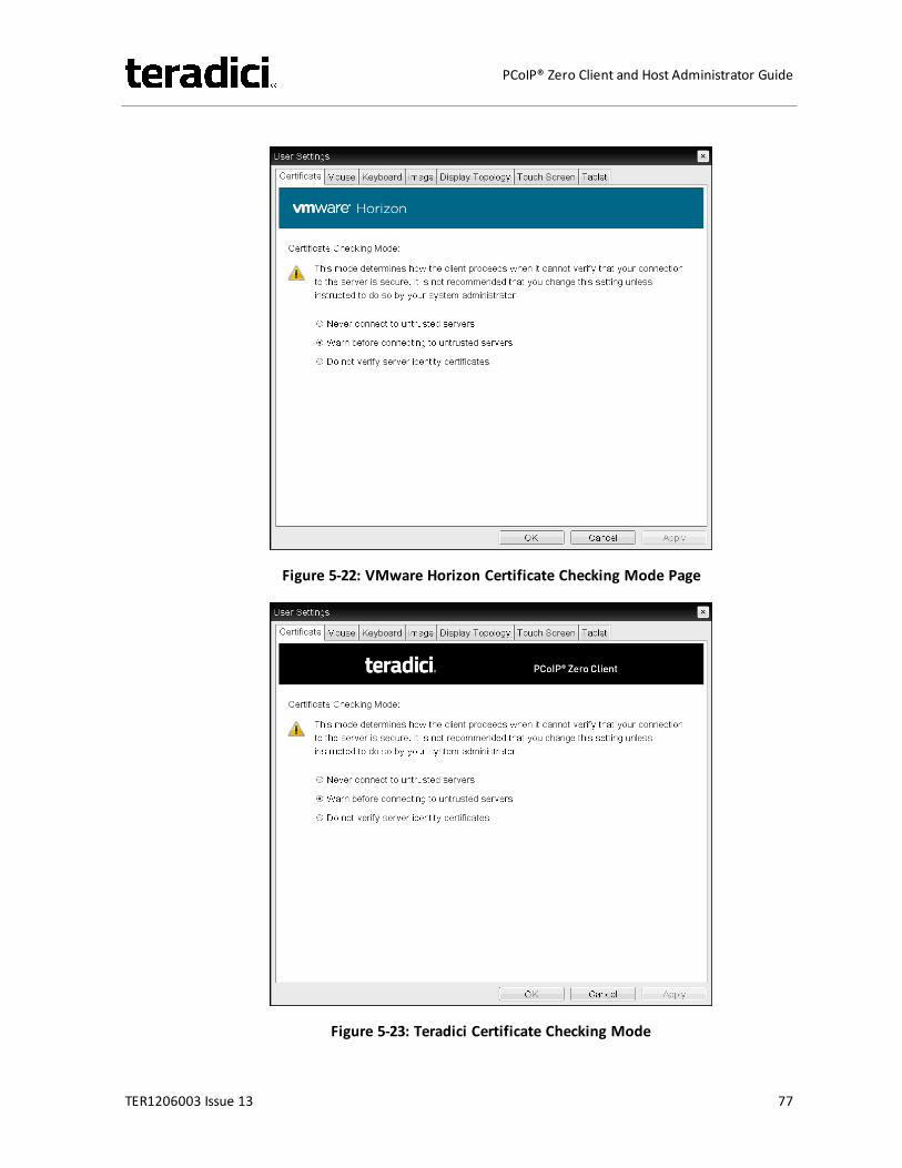
Figure 5-22: VMware Horizon Certificate Checking Mode Page
Figure 5-23: Teradici Certificate Checking Mode
TER1206003 Issue 13 77
PCoIP® Zero Client and Host Administrator Guide
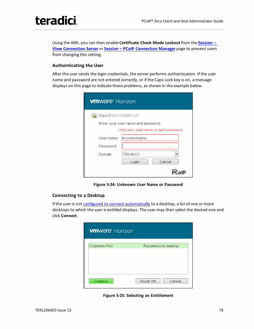
Using the AWI, you can then enable Certificate Check Mode Lockout from the Session –View Connection Server or Session – PCoIP Connection Manager page to prevent usersfrom changing this setting.
Authenticating the User
After the user sends the login credentials, the server performs authentication. If the username and password are not entered correctly, or if the Caps Lock key is on, a messagedisplays on this page to indicate these problems, as shown in the example below.
Figure 5-24: Unknown User Name or Password
Connecting to a Desktop
If the user is not configured to connect automatically to a desktop, a list of one or moredesktops to which the user is entitled displays. The user may then select the desired one andclick Connect.
Figure 5-25: Selecting an Entitlement
TER1206003 Issue 13 78
PCoIP® Zero Client and Host Administrator Guide
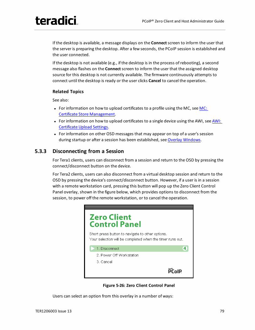
If the desktop is available, a message displays on the Connect screen to inform the user thatthe server is preparing the desktop. After a few seconds, the PCoIP session is established andthe user connected.
If the desktop is not available (e.g., if the desktop is in the process of rebooting), a secondmessage also flashes on the Connect screen to inform the user that the assigned desktopsource for this desktop is not currently available. The firmware continuously attempts toconnect until the desktop is ready or the user clicks Cancel to cancel the operation.
Related Topics
See also:
l For information on how to upload certificates to a profile using theMC, seeMC:Certificate StoreManagement.
l For information on how to upload certificates to a single device using the AWI, see AWI:Certificate Upload Settings.
l For information on other OSDmessages that may appear on top of a user's sessionduring startup or after a session has been established, see Overlay Windows.
5.3.3 Disconnecting from a SessionFor Tera1 clients, users can disconnect from a session and return to the OSD by pressing theconnect/disconnect button on the device.
For Tera2 clients, users can also disconnect from a virtual desktop session and return to theOSD by pressing the device's connect/disconnect button. However, if a user is in a sessionwith a remote workstation card, pressing this button will pop up the Zero Client ControlPanel overlay, shown in the figure below, which provides options to disconnect from thesession, to power off the remote workstation, or to cancel the operation.
Figure 5-26: Zero Client Control Panel
Users can select an option from this overlay in a number of ways:
TER1206003 Issue 13 79
PCoIP® Zero Client and Host Administrator Guide
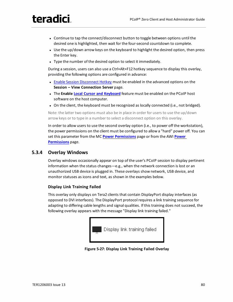
l Continue to tap the connect/disconnect button to toggle between options until thedesired one is highlighted, then wait for the four-second countdown to complete.
l Use the up/down arrow keys on the keyboard to highlight the desired option, then pressthe Enter key.
l Type the number of the desired option to select it immediately.
During a session, users can also use a Ctrl+Alt+F12 hotkey sequence to display this overlay,providing the following options are configured in advance:
l Enable Session Disconnect Hotkey must be enabled in the advanced options on theSession – View Connection Server page.
l The Enable Local Cursor and Keyboard featuremust be enabled on the PCoIP hostsoftware on the host computer.
l On the client, the keyboard must be recognized as locally connected (i.e., not bridged).
Note: the latter two options must also be in place in order for users to use the up/downarrow keys or to type in a number to select a disconnect option on this overlay.
In order to allow users to use the second overlay option (i.e., to power off the workstation),the power permissions on the client must be configured to allow a "hard" power off. You canset this parameter from theMC Power Permissions page or from the AWI PowerPermissions page.
5.3.4 Overlay WindowsOverlay windows occasionally appear on top of the user's PCoIP session to display pertinentinformation when the status changes—e.g., when the network connection is lost or anunauthorized USB device is plugged in. These overlays show network, USB device, andmonitor statuses as icons and text, as shown in the examples below.
Display Link Training Failed
This overlay only displays on Tera2 clients that contain DisplayPort display interfaces (asopposed to DVI interfaces). The DisplayPort protocol requires a link training sequence foradapting to differing cable lengths and signal qualities. If this training does not succeed, thefollowing overlay appears with themessage "Display link training failed."
Figure 5-27: Display Link Training Failed Overlay
TER1206003 Issue 13 80
PCoIP® Zero Client and Host Administrator Guide
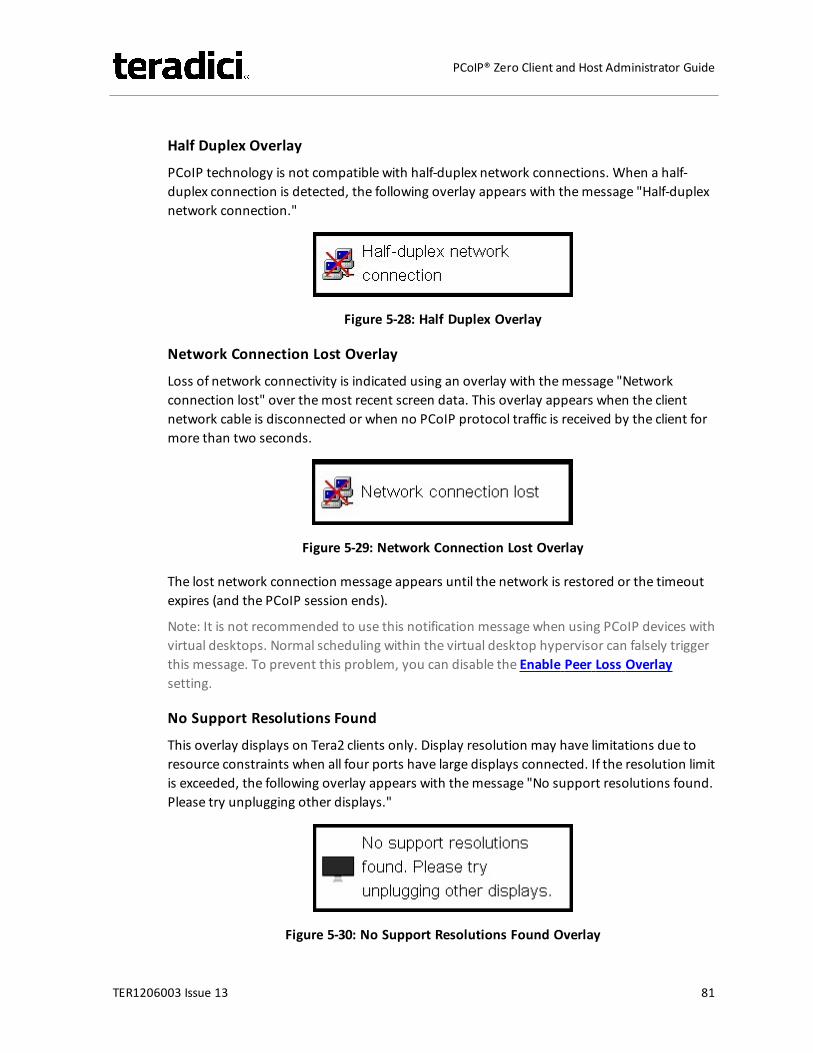
Half Duplex Overlay
PCoIP technology is not compatible with half-duplex network connections. When a half-duplex connection is detected, the following overlay appears with themessage "Half-duplexnetwork connection."
Figure 5-28: Half Duplex Overlay
Network Connection Lost Overlay
Loss of network connectivity is indicated using an overlay with themessage "Networkconnection lost" over themost recent screen data. This overlay appears when the clientnetwork cable is disconnected or when no PCoIP protocol traffic is received by the client formore than two seconds.
Figure 5-29: Network Connection Lost Overlay
The lost network connection message appears until the network is restored or the timeoutexpires (and the PCoIP session ends).
Note: It is not recommended to use this notification message when using PCoIP devices withvirtual desktops. Normal scheduling within the virtual desktop hypervisor can falsely triggerthis message. To prevent this problem, you can disable the Enable Peer Loss Overlaysetting.
No Support Resolutions Found
This overlay displays on Tera2 clients only. Display resolution may have limitations due toresource constraints when all four ports have large displays connected. If the resolution limitis exceeded, the following overlay appears with themessage "No support resolutions found.Please try unplugging other displays."
Figure 5-30: No Support Resolutions Found Overlay
TER1206003 Issue 13 81
PCoIP® Zero Client and Host Administrator Guide
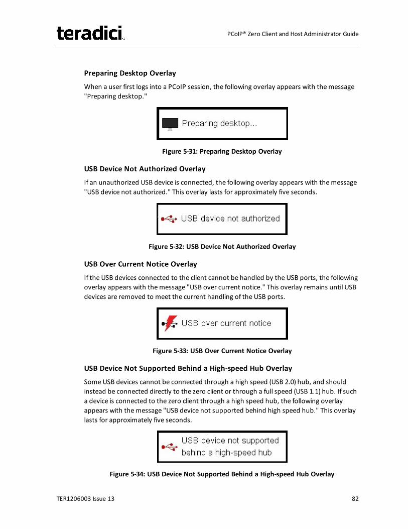
Preparing Desktop Overlay
When a user first logs into a PCoIP session, the following overlay appears with themessage"Preparing desktop."
Figure 5-31: Preparing Desktop Overlay
USB Device Not Authorized Overlay
If an unauthorized USB device is connected, the following overlay appears with themessage"USB device not authorized." This overlay lasts for approximately five seconds.
Figure 5-32: USB Device Not Authorized Overlay
USB Over Current Notice Overlay
If the USB devices connected to the client cannot be handled by the USB ports, the followingoverlay appears with themessage "USB over current notice." This overlay remains until USBdevices are removed to meet the current handling of the USB ports.
Figure 5-33: USB Over Current Notice Overlay
USB Device Not Supported Behind a High-speed Hub Overlay
Some USB devices cannot be connected through a high speed (USB 2.0) hub, and shouldinstead be connected directly to the zero client or through a full speed (USB 1.1) hub. If sucha device is connected to the zero client through a high speed hub, the following overlayappears with themessage "USB device not supported behind high speed hub." This overlaylasts for approximately five seconds.
Figure 5-34: USB Device Not Supported Behind a High-speed Hub Overlay
TER1206003 Issue 13 82
PCoIP® Zero Client and Host Administrator Guide
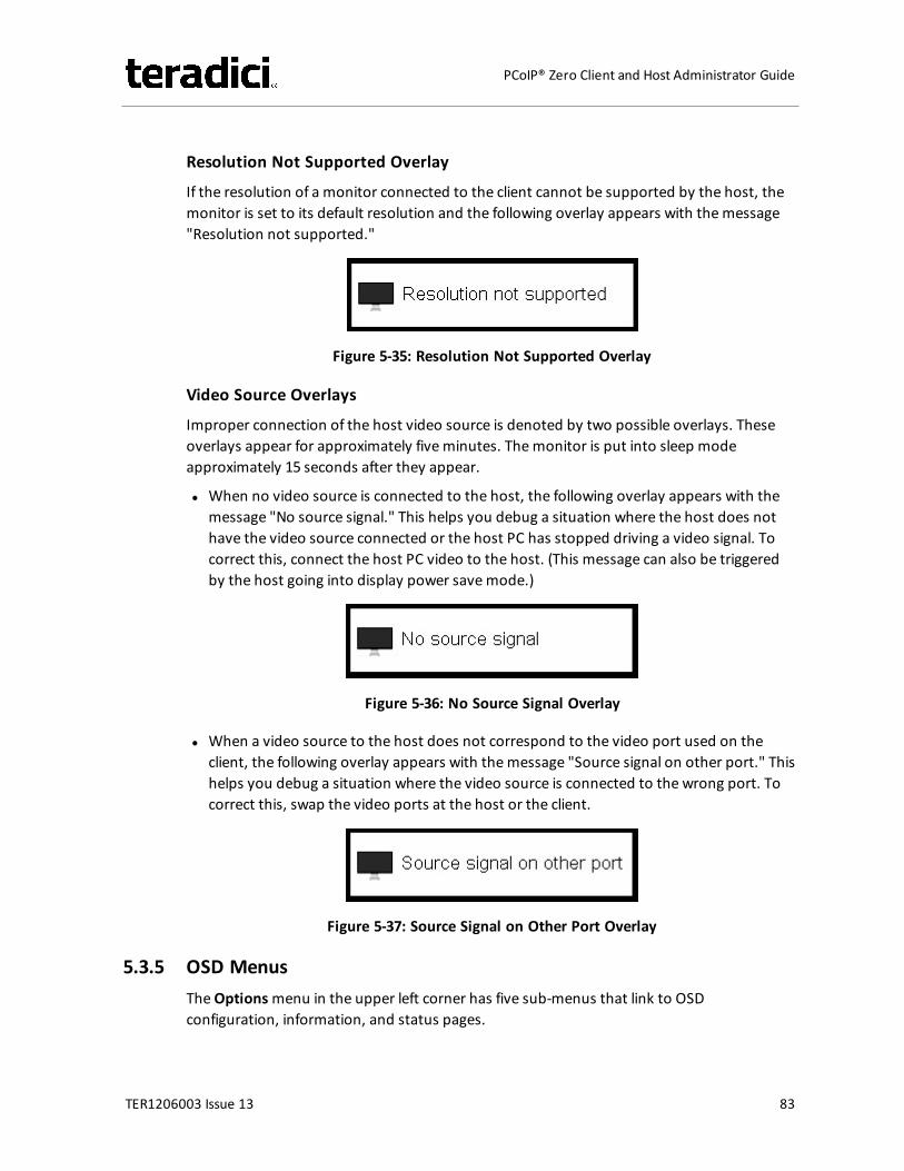
Resolution Not Supported Overlay
If the resolution of a monitor connected to the client cannot be supported by the host, themonitor is set to its default resolution and the following overlay appears with themessage"Resolution not supported."
Figure 5-35: Resolution Not Supported Overlay
Video Source Overlays
Improper connection of the host video source is denoted by two possible overlays. Theseoverlays appear for approximately fiveminutes. Themonitor is put into sleep modeapproximately 15 seconds after they appear.
l When no video source is connected to the host, the following overlay appears with themessage "No source signal." This helps you debug a situation where the host does nothave the video source connected or the host PC has stopped driving a video signal. Tocorrect this, connect the host PC video to the host. (This message can also be triggeredby the host going into display power savemode.)
Figure 5-36: No Source Signal Overlay
l When a video source to the host does not correspond to the video port used on theclient, the following overlay appears with themessage "Source signal on other port." Thishelps you debug a situation where the video source is connected to the wrong port. Tocorrect this, swap the video ports at the host or the client.
Figure 5-37: Source Signal on Other Port Overlay
5.3.5 OSD MenusTheOptionsmenu in the upper left corner has five sub-menus that link to OSDconfiguration, information, and status pages.
TER1206003 Issue 13 83
PCoIP® Zero Client and Host Administrator Guide
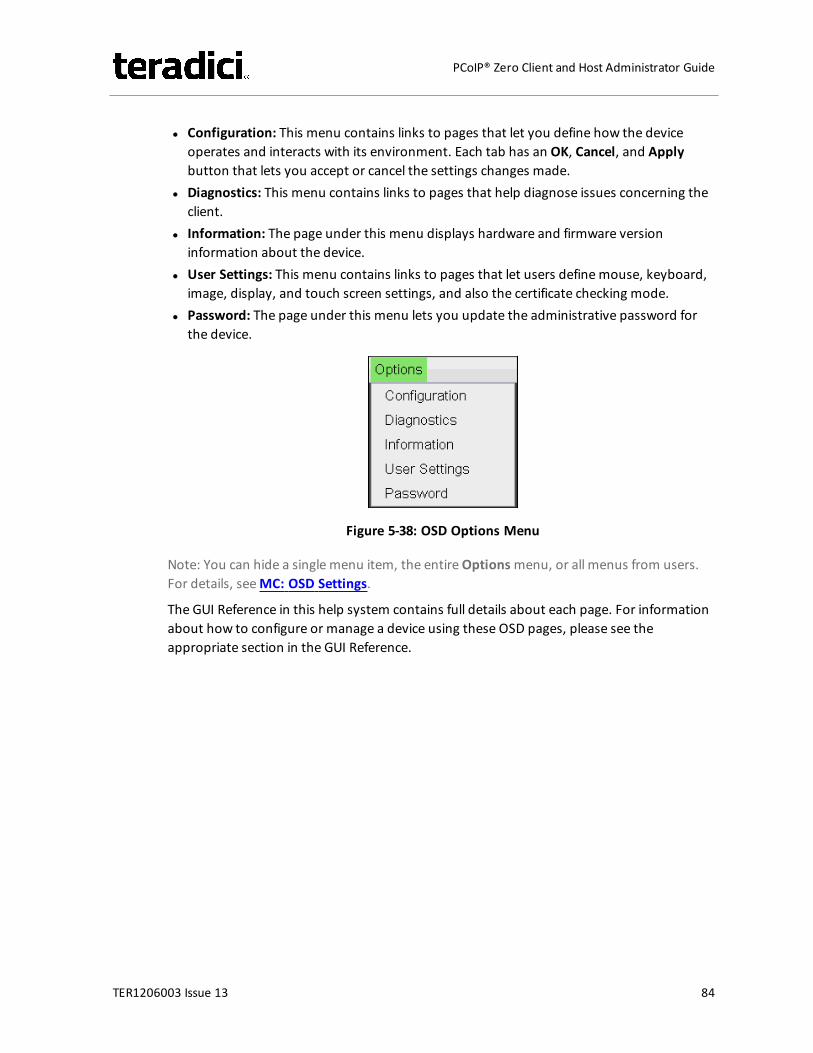
l Configuration: This menu contains links to pages that let you define how the deviceoperates and interacts with its environment. Each tab has an OK, Cancel, and Applybutton that lets you accept or cancel the settings changes made.
l Diagnostics: This menu contains links to pages that help diagnose issues concerning theclient.
l Information: The page under this menu displays hardware and firmware versioninformation about the device.
l User Settings: This menu contains links to pages that let users definemouse, keyboard,image, display, and touch screen settings, and also the certificate checking mode.
l Password: The page under this menu lets you update the administrative password forthe device.
Figure 5-38: OSD Options Menu
Note: You can hide a single menu item, the entireOptionsmenu, or all menus from users.For details, seeMC: OSD Settings.
The GUI Reference in this help system contains full details about each page. For informationabout how to configure or manage a device using these OSD pages, please see theappropriate section in the GUI Reference.
TER1206003 Issue 13 84
PCoIP® Zero Client and Host Administrator Guide
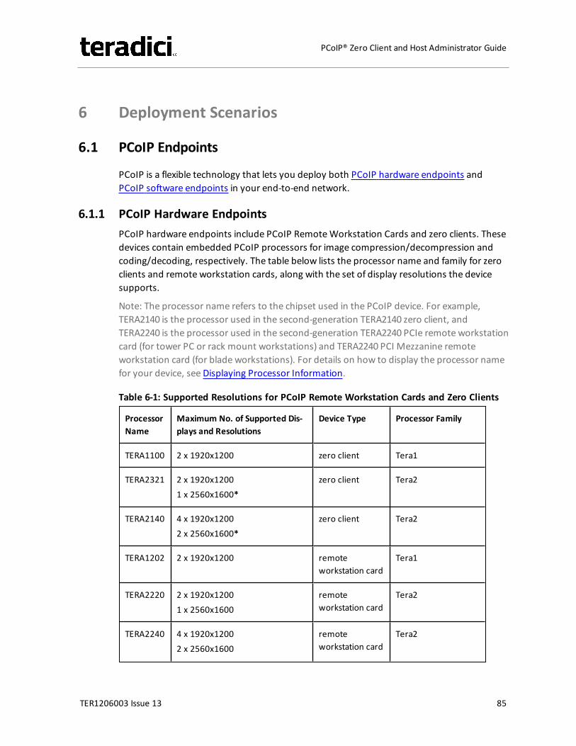
6 Deployment Scenarios
6.1 PCoIP Endpoints
PCoIP is a flexible technology that lets you deploy both PCoIP hardware endpoints andPCoIP software endpoints in your end-to-end network.
6.1.1 PCoIP Hardware EndpointsPCoIP hardware endpoints include PCoIP RemoteWorkstation Cards and zero clients. Thesedevices contain embedded PCoIP processors for image compression/decompression andcoding/decoding, respectively. The table below lists the processor name and family for zeroclients and remote workstation cards, along with the set of display resolutions the devicesupports.
Note: The processor name refers to the chipset used in the PCoIP device. For example,TERA2140 is the processor used in the second-generation TERA2140 zero client, andTERA2240 is the processor used in the second-generation TERA2240 PCIe remote workstationcard (for tower PC or rack mount workstations) and TERA2240 PCI Mezzanine remoteworkstation card (for blade workstations). For details on how to display the processor namefor your device, see Displaying Processor Information.
Table 6-1: Supported Resolutions for PCoIP Remote Workstation Cards and Zero Clients
ProcessorName
Maximum No. of Supported Dis-plays and Resolutions
Device Type Processor Family
TERA1100 2 x 1920x1200 zero client Tera1
TERA2321 2 x 1920x12001 x 2560x1600*
zero client Tera2
TERA2140 4 x 1920x12002 x 2560x1600*
zero client Tera2
TERA1202 2 x 1920x1200 remoteworkstation card
Tera1
TERA2220 2 x 1920x12001 x 2560x1600
remoteworkstation card
Tera2
TERA2240 4 x 1920x12002 x 2560x1600
remoteworkstation card
Tera2
TER1206003 Issue 13 85
PCoIP® Zero Client and Host Administrator Guide
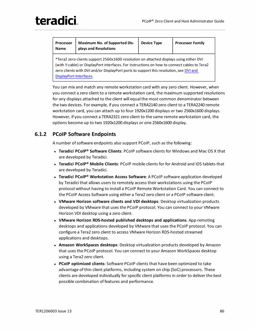
ProcessorName
Maximum No. of Supported Dis-plays and Resolutions
Device Type Processor Family
*Tera2 zero clients support 2560x1600 resolution on attached displays using either DVI(with Y-cable) or DisplayPort interfaces. For instructions on how to connect cables to Tera2zero clients with DVI and/or DisplayPort ports to support this resolution, see DVI andDisplayPort Interfaces.
You can mix and match any remote workstation card with any zero client. However, whenyou connect a zero client to a remote workstation card, themaximum supported resolutionsfor any displays attached to the client will equal themost common denominator betweenthe two devices. For example, if you connect a TERA2140 zero client to a TERA2240 remoteworkstation card, you can attach up to four 1920x1200 displays or two 2560x1600 displays.However, if you connect a TERA2321 zero client to the same remote workstation card, theoptions become up to two 1920x1200 displays or one 2560x1600 display.
6.1.2 PCoIP Software EndpointsA number of software endpoints also support PCoIP, such as the following:
l Teradici PCoIP® Software Clients: PCoIP software clients for Windows and Mac OS X thatare developed by Teradici.
l Teradici PCoIP® Mobile Clients: PCoIP mobile clients for for Android and iOS tablets thatare developed by Teradici.
l Teradici PCoIP® Workstation Access Software: A PCoIP software application developedby Teradici that allows users to remotely access their workstations using the PCoIPprotocol without having to install a PCoIP RemoteWorkstation Card. You can connect tothe PCoIP Access Software using either a Tera2 zero client or a PCoIP software client.
l VMware Horizon software clients and VDI desktops: Desktop virtualization productsdeveloped by VMware that uses the PCoIP protocol. You can connect to your VMwareHorizon VDI desktop using a zero client.
l VMware Horizon RDS-hosted published desktops and applications. App-remotingdesktops and applications developed by VMware that uses the PCoIP protocol. You canconfigure a Tera2 zero client to access VMware Horizon RDS-hosted streamedapplications and desktops.
l Amazon WorkSpaces desktops: Desktop virtualization products developed by Amazonthat uses the PCoIP protocol. You can connect to your Amazon WorkSpaces desktopusing a Tera2 zero client.
l PCoIP optimized clients: Software PCoIP clients that have been optimized to takeadvantage of thin client platforms, including system on chip (SoC) processors. Theseclients are developed individually for specific client platforms in order to deliver the bestpossible combination of features and performance.
TER1206003 Issue 13 86
PCoIP® Zero Client and Host Administrator Guide
6.2 Connection Types
Most connection types are configured from the Configuration > Sessionmenu in the AWI orOSD and the Profiles > Session Configurationmenu in theMC. One exception is the ZeroClient-to-Bria Softphone Caller Endpoint connection type, which is configured from theConfiguration > Unified Communicationsmenu in the AWI and the Profiles > UnifiedCommunications Configurationmenu in theMC.
The zero client supports the following session connection types:
l Zero Client–to–RemoteWorkstation Card Connectionsl Zero Client–to–PCoIP Connection Manager Connections
l Teradici PCoIP®Workstation Access Software Connectionsl Amazon WorkSpaces Connections
l Zero Client–to–VMware Horizon VDI, DaaS, and RDS-hosted App-remoting Connectionsl Zero Client–to–Bria Softphone Caller Endpoint Connections
6.2.1 Zero Client–to–Remote Workstation Card ConnectionsYou can move high-performanceWindows or Linux workstations with PCoIP RemoteWorkstation Cards into your data center, and then configure sessions between zero clientsand these workstation hosts over a LAN orWAN. This type of configuration provides asecure, reliable, and easy-to-manage solution that meets the needs of users who havededicated computers with graphically demanding applications.
Depending on the size of your PCoIP deployment, you may wish to use theMC or aconnection broker to manage connections between remote workstation cards and zeroclients, or you may use the AWI to configure individual hosts and clients remotely. You caneven use the OSD to configure settings for a specific zero client.
The following session connection types are available for zero client-to-remote workstationcard connections:
l Connecting staticallyl Connecting using SLP host discoveryl Connecting using a 3rd party connection brokerl Connecting using the View Connection Server broker
For information on the prerequisites for these connection types, see Zero Client–to–RemoteWorkstation Card Prequisites.
Connecting Statically
To statically configure a zero client to connect directly to a specific remote workstation card,use theDirect to Host session connection type. You will need to provide the DNS name or IPaddress of the remote workstation card for this option.
TER1206003 Issue 13 87
PCoIP® Zero Client and Host Administrator Guide
You also need to configure a Direct from Client session connection type on the remoteworkstation card. You have the option of allowing the host to accept a connection requestfrom any client or from a specific client only. If the latter, you need to provide the client'sMAC address.
For details on how to configure this option, see the following topics in the GUI Reference:
l MC: Direct to Host: Explains how to use theMC to configure a profile that sets theDirectto Host session connection type for zero clients. For information on how to statically linkspecific hosts and clients using theMC, see “Teradici PCoIP®Management Console UserManual” (TER0812002) in the Teradici Support Documentation Center.
l AWI Client: Direct to Host: Explains how to use the AWI to statically configure a zero clientto connect to a specific remote workstation card.
l AWI Host: Direct from Client: Explains how to use the AWI to configure a remoteworkstation card to accept a connection request from any zero client or from a specificzero client only.
l OSD: Direct to Host: Explains how to use the OSD to statically configure a zero client toconnect to a specific remote workstation card.
Connecting Using SLP Host Discovery
If remote workstation cards reside on the same subnet as zero clients, you can use theDirectto Host + SLP session connection type to configure clients to use Service Location Protocol(SLP) to discover the remote workstation cards on the subnet. With this configuration, theclient OSD will list the first 10 cards discovered. The user can then select the desired one andconnect to it.
Note: SLP host discovery is not suitable for deployments with more than 10 hosts if a zeroclient needs to connect to a specific host all the time. In this situation, a 3rd party connectionbroker is required.
You also need to configure a Direct from Client session connection type on the remoteworkstation card. You have the option of allowing the host to accept a connection requestfrom any zero client or from a specific one only. If the latter, you need to provide the client'sMAC address.
For details on how to configure this option, see the following topics in the GUI Reference:
l MC: Direct to Host + SLP: Explains how to use theMC to configure a profile that sets theDirect to Host + SLP session connection type for zero clients.
l AWI Client: Direct to Host + SLP: Explains how to use the AWI to configure a zero client touse SLP discovery to connect to a remote workstation card.
l AWI Host: Direct from Client: Explains how to use the AWI to configure a remoteworkstation card to accept a connection request from any zero client or from a specificclient only.
l OSD: Direct to Host + SLP: Explains how to use the OSD to configure a zero client to useSLP discovery to connect to a remote workstation card.
TER1206003 Issue 13 88
PCoIP® Zero Client and Host Administrator Guide
Connecting Using a 3rd Party Connection Broker
A 3rd party connection broker is a resourcemanager that dynamically assigns host PCscontaining remote workstation cards to zero clients based on the identity of the userestablishing a connection from the zero client. Connection brokers are also used to allocate apool of hosts to a group of zero clients. They are typically used in large PCoIP deployments,or when hosts and clients do not reside on the same subnet.
Use the Connection Management Interface session connection type on both the host andclient for this option. You need to provide the DNS name or IP address for the 3rd partyconnection broker.
Note: For information about 3rd party connection brokers, see KB 15134-24 in the TeradiciSupport Site.
For details on how to configure this option, see the following topics in the GUI Reference:
l MC: Connection Management Interface: Explains how to use theMC to configure aprofile that sets the Connection Management Interface session connection type for zeroclients and remote workstation cards.
l AWI Client: Connection Management Interface: Explains how to use the AWI to configurea zero client to use a 3rd party connection broker to broker the connection between zeroclients and remote workstation cards.
l AWI Host: Connection Management Interface: Explains how to use the AWI to configure aremote workstation card to use a 3rd party connection broker for accepting a connectionrequest from a zero client.
l OSD: Connection Management Interface: Explains how to use the OSD to configure a zeroclient to use a 3rd party connection broker to broker the connection between a zeroclient and remote workstation card.
Connecting Using the View Connection Server Broker
You can also use a View Connection Server to broker a connection between zero clients andremote workstation cards.
Note: This is not the same thing as configuring a zero client to connect to a VMware Horizonvirtual desktop using a View Connection Server.
For this option, VMware ViewAgent must be installed on the remote workstation, and anumber of other configuration requirements for both the client and host must be in place.For complete details, please refer to “Using PCoIP® Host Cards with VMware View”(TER0911004) in the Teradici Support Documentation Center.
6.2.2 Zero Client–to–PCoIP Connection Manager ConnectionsThe PCoIP Connection Manager implements the PCoIP Broker Protocol for authenticationand session initiation. The PCoIP Connection Manager session connection type can be usedto connect Tera2 zero clients to the following types of remote PCoIP endpoints:
TER1206003 Issue 13 89
PCoIP® Zero Client and Host Administrator Guide
l Teradici PCoIP® Workstation Access Software: The PCoIP Access Software is a Teradiciapplication installed on a remote workstation that allows you to remotely access yourworkstation using the PCoIP protocol without having to install a remote workstationcard. Using a Tera2 zero client, you can connect to your PCoIP Access Software using thePCoIP Connection Manager or Auto Detect session connection type. For details on howto install the PCoIP Access Software in a workstation and use a Tera2 zero client toestablish a session, please see “Teradici PCoIP®Workstation Access Software User Guide"(TER1405004) in the Teradici Support Documentation Center. For information on theprerequisites for this connection type, see Zero Client–to–PCoIP Workstation AccessSoftware Prerequisites.
l Amazon WorkSpaces: Amazon WorkSpaces is Amazon's desktop computing service inthe cloud where cloud-based desktops are provisioned for end users. Using a Tera2 zeroclient, you can use the PCoIP Connection Manager or Auto Detect session connectiontype to connect to yourWorkSpaces desktop. For details on how to install and configurethe necessary components, and how to use a Tera2 zero client to establish a session,please see "Connecting PCoIP® Zero Clients to Amazon WorkSpaces" (TER1408002) in theTeradici Support Documentation Center. For information on the prerequisites for thisconnection type, see Zero Client–to–Amazon WorkSpaces Prerequisites.
The following session connection types are available for zero client-to-PCoIP ConnectionManager connections:
l Auto Detectl PCoIP Connection Managerl PCoIP Connection Manager + Auto-Logon
Auto Detect
To configure a Tera2 zero client to automatically detect the right broker to use on the OSDConnect screen, use the Auto Detect session connection type and configure the URI for yourbroker (e.g., a PCoIP Connection Manager or View Connection Server). After making asuccessful connection, you can select this URI from the Server drop-down list on the OSDConnect screen.
For details on how to configure this option, see the following topics in the GUI Reference:
l MC: Auto Detect: Explains how to use theMC to configure a profile that sets the AutoDetect session connection type for zero clients.
l AWI Tera2 Client: Auto Detect: Explains how to use the AWI to configure a zero client toautomatically detect the broker to use on the OSD Connect screen.
l OSD Tera2: Auto Detect: Explains how to use the OSD to configure a zero client toautomatically detect the broker to use on the OSD Connect screen.
TER1206003 Issue 13 90
PCoIP® Zero Client and Host Administrator Guide
PCoIP Connection Manager
To configure a zero client to connect to a PCoIP Access Software instance that is installed in aremote workstation or to an Amazon WorkSpaces desktop, use the PCoIP ConnectionManager session connection type. You will need to provide the appropriate server URI forthe connection type. For instructions, please see “Teradici PCoIP®Workstation AccessSoftware User Guide" (TER1405004) and "Connecting PCoIP® Zero Clients to AmazonWorkSpaces" (TER1408002), respectively.
For details on how to configure this option, see the following topics in the GUI Reference:
l MC: PCoIP Connection Manager: Explains how to use theMC to configure a profile thatsets the PCoIP Connection Manager session connection type for zero clients.
l AWI Client: PCoIP Connection Manager: Explains how to use the AWI to configure a clientto use the PCoIP Connection Manager session connection type.
l OSD: PCoIP Connection Manager: Explains how to use the AWI to configure a client touse the PCoIP Connection Manager session connection type.
PCoIP Connection Manager + Auto-Logon
You can also use the PCoIP Connection Manager + Auto-Logon session connection type toautomatically enter user login details when connecting in PCoIP Connection Manager mode.Besides the appropriate server URI, you will need to provide a user name, user password,and domain name.
For details on how to configure this option, see the following topics in the GUI Reference:
l MC: PCoIP Connection Manager + Auto-Logon: Explains how to use theMC to configure aprofile that sets the PCoIP Connection Manager + Auto-Logon session connection typefor zero clients. This session connection type is useful when you want to set a default username and password in a profile.
l AWI Client: PCoIP Connection Manager + Auto-Logon: Explains how to use the AWI toconfigure a client to automatically send user login details when connecting in PCoIPConnection Manager mode.
l OSD: PCoIP Connection Manager + Auto-Logon: Explains how to use the OSD to configurea client to automatically send user login details when connecting in PCoIP ConnectionManager mode.
6.2.3 Zero Client–to–VMware Horizon ConnectionsYou can configure zero clients to use the PCoIP protocol when connecting to desktops in aVMware Horizon VDI or DaaS environment, or when connecting to VMware Horizon app-remoting desktops and applications published on an RDS server.
Note: VMWare Horizon RDS-hosted application connections are supported on the ViewConnection Server, View Connection Server + Auto-Logon, View Connection Server +Kiosk, and View Connection Server + Imprivata OneSign session types for Tera2 zero
TER1206003 Issue 13 91
PCoIP® Zero Client and Host Administrator Guide
clients. After configuring your View Connection Server, select the Enable RDS ApplicationAccess check box in Advanced Options on the Session page.
Depending on the size of your PCoIP deployment, you may wish to use theMC to configurea profile with a View Connection Server session connection type, or you may use the AWI orthe OSD to configure an individual zero client to use a View Connection Server sessionconnection type.
The following session connection types are available for zero client-to-VMware Horizon VDIconnections:
l View Connection Serverl View Connection Server + Auto-Logonl View Connection Server + Kioskl View Connection Server + Imprivata OneSign
For information on the prerequisites for these connection types, see Zero Client–to–VMwareHorizon Prerequisites.
Auto Detect
To configure a Tera2 zero client to automatically detect the right broker to use on the OSDConnect screen, use the Auto Detect session connection type and configure the URI for yourbroker (e.g., a PCoIP Connection Manager or View Connection Server). After making asuccessful connection, you can select this URI from the Server drop-down list on the OSDConnect screen.
For details on how to configure this option, see the following topics in the GUI Reference:
l MC: Auto Detect: Explains how to use theMC to configure a profile that sets the AutoDetect session connection type for zero clients.
l AWI Tera2 Client: Auto Detect: Explains how to use the AWI to configure a zero client toautomatically detect the broker to use on the OSD Connect screen.
l OSD Tera2: Auto Detect: Explains how to use the OSD to configure a zero client toautomatically detect the broker to use on the OSD Connect screen.
View Connection Server
To configure a zero client to connect to a VMware virtual desktop with a manual logon, usethe View Connection Server session connection type. You will need to provide the DNSname or IP address of the View Connection Server.
For details on how to configure this option, see the following topics in the GUI Reference:
l MC: View Connection Server: Explains how to use theMC to configure a profile that setsthe View Connection Server session connection type for zero clients.
l AWI Client: View Connection Server: Explains how to use the AWI to configure a zeroclient to use the View Connection Server session connection type.
TER1206003 Issue 13 92
PCoIP® Zero Client and Host Administrator Guide
l OSD: View Connection Server: Explains how to use the OSD to configure a zero client touse the View Connection Server session connection type.
View Connection Server + Auto-Logon
To configure zero clients to automatically enter user login details when zero clients connectto a virtual desktop, use the View Connection Server + Auto-Logon session connectiontype. You will need to provide the DNS name or IP address of the View Connection Server,and also the user name, user password, and the domain name to send to the server.
For details on how to configure this option, see the following topics in the GUI Reference:
l MC: View Connection Server + Auto-Logon: Explains how to use theMC to configure aprofile that sets the View Connection Server + Auto-Logon session connection type forzero cllients. This session connection type is useful when you want to set a default username and password in a profile.
l AWI Client: View Connection Server + Auto-Logon: Explains how to use the AWI toconfigure a zero client to automatically send user login details when connecting to aHorizon desktop.
l OSD: View Connection Server + Auto-Logon: Explains how to use the OSD to configure azero client to automatically send user login details when connecting to a Horizondesktop.
View Connection Server + Kiosk
View Connection Server + Kiosk mode allows you to configure zero clients to connect to adesktop that will be used for a kiosk implementation, such as when multiple users connectto a desktop to obtain information that is not specific to any one individual. At minimum,you will need to provide the DNS name or IP address of the View Connection Server and thekiosk user name—either a custom user name for the kiosk or its MAC address.
For details on how to configure this option, see the following topics in the GUI Reference:
l MC: View Connection Server + Kiosk: Explains how to use theMC to configure a profilethat sets the View Connection Server + Kiosk session connection type for zero clients.
l AWI Client: View Connection Server + Kiosk: Explains how to use the AWI to configure azero client to use Kiosk modewhen connecting to a Horizon desktop.
l OSD: View Connection Server + Kiosk: Explains how to use the OSD to configure a zeroclient to use Kiosk modewhen connecting to a Horizon desktop.
View Connection Server + Imprivata OneSign
View Connection Server + Imprivata OneSign mode allows you to configure zero clients touse Imprivata OneSign proximity card support when connecting to a virtual desktop via aView Connection Server. You will need to provide the DNS name or IP address of the ViewConnection Server and the bootstrap URL for the OneSign server.
For details on how to configure this option, see the following topics in the GUI Reference:
TER1206003 Issue 13 93
PCoIP® Zero Client and Host Administrator Guide
l MC: View Connection Server + Imprivata OneSign: Explains how to use theMC toconfigure a profile that sets the View Connection Server + Imprivata OneSign sessionconnection type for zero clients.
l AWI Client: View Connection Server + Imprivata OneSign: Explains how to use the AWI toconfigure a zero client to use Imprivata OneSign modewhen connecting to a Horizondesktop.
l OSD: View Connection Server + Imprivata OneSign: Explains how to use the OSD toconfigure a zero client to use Imprivata OneSign modewhen connecting to a Horizondesktop.
6.2.4 Zero Client–to–Bria Softphone Caller Endpoint ConnectionsThe zero client supports interoperability with CounterPath's Bria Virtualized Edition for PCoIPZero Clients softphone client installed on a VMware Horizon View or Horizon DaaS desktop.
After using a zero client to connect to a Horizon desktop or an Amazon WorkSpaces desktop,users can initiate Unified Communications (UC) services (e.g., voice, messaging, presenceinformation, and contacts) to caller endpoints using a Bria Virtualized Edition softphoneclient that is installed on their desktop. Once the Bria client establishes the connection, calltraffic is routed directly between the zero client and the caller endpoint, thus offloading thistraffic from the data center.
This feature is configured from the Configuration > Unified Communicationsmenu in theAWI and the Profiles > Unified Communications Configurationmenu in theMC. See AWITera2 Client: Unified Communications and MC: Unified Communications for details.
For information on the prerequisites for this connection type, see Zero Client–to–BriaSoftphone Client Caller Endpoint Prerequisites.
For information on how to troubleshoot softphone calls, see AWI Tera2 Client: PacketCapture.
6.3 Connection Prerequisites
This section lists basic requirements for the following connection types you can make usingzero clients and remote workstation cards:
l Zero Client–to–RemoteWorkstation Card Prerequisitesl PCoIP Software Client–to–RemoteWorkstation Card Prerequisitesl Zero Client–to–PCoIP Workstation Access Software Prerequisitesl Zero Client–to–Amazon WorkSpaces Prerequisitesl Zero Client–to–VMware Horizon Prerequisitesl Zero Client–to–Bria Softphone Caller Endpoint Prerequisites
TER1206003 Issue 13 94
PCoIP® Zero Client and Host Administrator Guide
Downloading Firmware Note: To download a specific firmware version for a zero client orremote workstation card, log in to the Teradici Support Site, and then type the desiredfirmware version into the search box (e.g., "firmware x.x.x").
6.3.1 Zero Client–to–Remote Workstation Card PrerequisitesBefore connecting a zero client to a remote workstation card, please ensure that thefollowing prerequisites are in place:
l The remote workstation card and zero client have the same firmware versions. Forinformation on how to assign a firmware file to a profile using theMC, seeMC: FirmwareManagement. For information on how to upload firmware to a single host or client usingthe AWI, see Uploading Firmware.
l You are running a supported OS on the workstation and the Teradici PCoIP host softwareis installed. For details, please see “PCoIP® Host Software for Windows User Guide”(TER1008001) or “PCoIP® Host Software for Linux User Guide” (TER1104006) in the TeradiciSupport Documentation Center. If you are using a VMware Connection Server as abroker, View Agent must also be installed on the host PC or workstation.
l The Host Driver Function is enabled on the remote workstation card.l Your network resources meet bandwidth, QoS, latency, jitter, and packet loss
requirements. For more information about designing PCoIP network architecture, see“PCoIP® Protocol Virtual Desktop Network Design Checklist” (TER1105004) in the TeradiciSupport Documentation Center.
6.3.2 PCoIP Software Client–to–Remote Workstation Card PrerequisitesBefore connecting a a PCoIP software client to a remote workstation card, please ensure thatthe following prerequisites are in place on the remote workstation card:
l The remote workstation card has firmware 4.2.0 or newer installed (see DownloadingFirmware Note).
l You are running a supported OS on the workstation and the Teradici PCoIP Host Softwaremust be installed in the workstation.
For details about PCoIP software client requirements, more information about remoteworkstation requirements, and instructions on how to configure the client to connect to aremote workstation card, please see “Teradici PCoIP® Software Clients User Guide”(TER1307002) in the Teradici Support Documentation Center.PCoIP Access SoftwarePCoIPAccess Software
6.3.3 Zero Client–to–PCoIP Workstation Access Software PrerequisitesBefore connecting a zero client to a workstation running the Teradici PCoIP®WorkstationAccess Software, please ensure that the following prerequisites are in place:
TER1206003 Issue 13 95
PCoIP® Zero Client and Host Administrator Guide
l You are using a Tera2 zero client (TERA2321 or TERA2140 processor) to connect.l Your zero client has firmware version 4.7.0 or newer installed (see Downloading Firmware
Note). For information on how to assign a firmware file to a profile using theMC, seeMC:FirmwareManagement. For information on how to upload firmware to a single host orclient using the AWI, see Uploading Firmware.
l The remote workstation has the PCoIP Access Software installed.
For details about PCoIP Access Software requirements, along with instructions on how toconnect to a PCoIP Access Software instance running on a workstation, please see “TeradiciPCoIP®Workstation Access Software User Guide" (TER1405004) in the Teradici SupportDocumentation Center.
6.3.4 Zero Client–to–Amazon WorkSpaces PrerequisitesBefore connecting a zero client to an Amazon WorkSpaces desktop, please ensure that thefollowing prerequisites are in place:
l You are using a Tera2 zero client (TERA2321 or TERA2140 processor) to connect.l Your zero client has firmware version 4.6.0 or newer installed (see Downloading Firmware
Note). For information on how to assign a firmware file to a profile using theMC, seeMC:FirmwareManagement. For information on how to upload firmware to a single host orclient using the AWI, see Uploading Firmware.
l You have an AWS account with Amazon WorkSpaces up and running. For information,please see AWS documentation.
l Your network has full connectivity to your Amazon WorkSpaces. For information, pleasesee AWS documentation.
l You have a PCoIP® Connection Manager for Amazon WorkSpaces appliance installed andconfigured. For more information, see "Connecting PCoIP® Zero Clients to AmazonWorkSpaces" (TER1408002) in the Teradici Support Documentation Center.
6.3.5 Zero Client–to–VMware Horizon PrerequisitesBefore connecting a zero client to a VMware Horizon desktop, please ensure that thefollowing prerequisites are in place:
l The VMware Horizon View installation, which includes the VMware ViewManager andVMware ViewAgent, are version 4.0.1 or newer. For information about VMware HorizonDaaS and VMware Horizon 6 prerequisites, please refer to VMware documentation. Forinformation on how to assign a firmware file to a profile using theMC, seeMC: FirmwareManagement. For information on how to upload firmware to a single host or client usingthe AWI, see Uploading Firmware.
l The zero client has firmware version 3.1.0 or newer installed. For connections to VMwareHorizon 6 RDS-hosted desktops, the zero client has firmware version 4.6.0 or newerinstalled. For connections to VMware Horizon 6 RDS-hosted applications, the zero clienthas firmware version 4.8.0 or newer installed.
TER1206003 Issue 13 96
PCoIP® Zero Client and Host Administrator Guide
l For VMware Horizon connections to RDS-hosted published desktops and applications,you are using a Tera2 zero client (TERA2321 or TERA2140 processor).
l Your network resources meet bandwidth, QoS, latency, jitter, and packet lossrequirements. For more information about designing PCoIP network architecture, see“PCoIP® Protocol Virtual Desktop Network Design Checklist” (TER1105004) in the TeradiciSupport Documentation Center.
6.3.6 Zero Client–to–Bria Softphone Caller Endpoint PrerequisitesBefore using a Bria Virtualized Edition softphone client to connect a zero client to a callerendpoint, please ensure that the following prerequisites are in place:
CounterPath Bria Virtualized Edition for PCoIP Zero Clients Softphone Clientrequirements:
l The CounterPath Bria Virtualized Edition softphone client is installed on a VMwareHorizon View desktop, a VMware Horizon DaaS desktop, or an Amazon WorkSpacesdesktop.
l Your system contains a SIP-compliant call server.l If instant messaging and presence information are desired, your system contains an
XMPP instant messaging and presence server.l You are using an analog headset (any type) or one of the following tested USB headsets:
l Plantronics Blackwire C310 and C320 USBl Plantronics Blackwire C435l Plantronics Blackwire C510 and C520l Plantronics Blackwire C710 and C720
Note: Other USB headsets may also work with this application, but have not beentested at this time.
Zero client requirements:
l You are using a Tera2 zero client (TERA2321 or TERA2140 processor) to connect.l Your zero client has firmware version 4.7.0 or newer installed (4.8.0 or newer for Bria
softphone support on Amazon WorkSpaces desktops). If your firmware version is prior to4.5.0, you must install a version 4.5.x or 4.6.0 firmware release before upgrading toversion 4.7.0. For more information about the firmware upgrade process, please see“TERA Firmware Release Notes Version 4.x” (TER1204003). For information on how toassign a firmware file to a profile using theMC, seeMC: FirmwareManagement. Forinformation on how to upload firmware to a single host or client using the AWI, seeUploading Firmware.
l You have enabled Unified Communications (UC) for the zero client. For details, seeMC:Unified Communications or AWI Tera2 Client: Unified Communications.
l You have purchased the required licenses for the Bria Virtualized Edition for PCoIP ZeroClients softphone. For more information, please visit the CounterPath store.
l If desired, you have configured VLAN tagging for QoS management of VoIP call data.
TER1206003 Issue 13 97
PCoIP® Zero Client and Host Administrator Guide
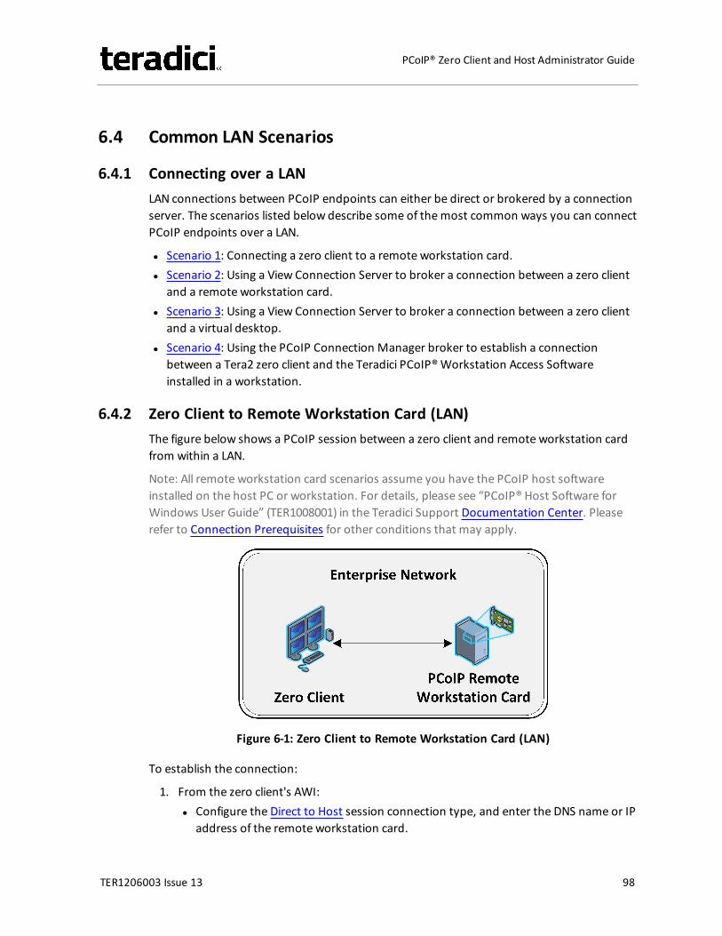
6.4 Common LAN Scenarios
6.4.1 Connecting over a LANLAN connections between PCoIP endpoints can either be direct or brokered by a connectionserver. The scenarios listed below describe some of themost common ways you can connectPCoIP endpoints over a LAN.
l Scenario 1: Connecting a zero client to a remote workstation card.l Scenario 2: Using a View Connection Server to broker a connection between a zero client
and a remote workstation card.l Scenario 3: Using a View Connection Server to broker a connection between a zero client
and a virtual desktop.l Scenario 4: Using the PCoIP Connection Manager broker to establish a connection
between a Tera2 zero client and the Teradici PCoIP®Workstation Access Softwareinstalled in a workstation.
6.4.2 Zero Client to Remote Workstation Card (LAN)The figure below shows a PCoIP session between a zero client and remote workstation cardfrom within a LAN.
Note: All remote workstation card scenarios assume you have the PCoIP host softwareinstalled on the host PC or workstation. For details, please see “PCoIP® Host Software forWindows User Guide” (TER1008001) in the Teradici Support Documentation Center. Pleaserefer to Connection Prerequisites for other conditions that may apply.
Figure 6-1: Zero Client to Remote Workstation Card (LAN)
To establish the connection:
1. From the zero client's AWI:l Configure the Direct to Host session connection type, and enter the DNS name or IP
address of the remote workstation card.
TER1206003 Issue 13 98
PCoIP® Zero Client and Host Administrator Guide
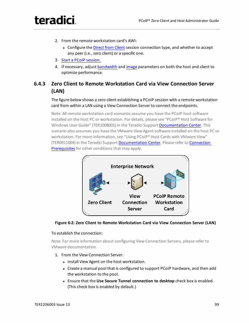
2. From the remote workstation card's AWI:l Configure the Direct from Client session connection type, and whether to accept
any peer (i.e., zero client) or a specific one.3. Start a PCoIP session.4. If necessary, adjust bandwidth and image parameters on both the host and client to
optimize performance.
6.4.3 Zero Client to Remote Workstation Card via View Connection Server(LAN)The figure below shows a zero client establishing a PCoIP session with a remote workstationcard from within a LAN using a View Connection Server to connect the endpoints.
Note: All remote workstation card scenarios assume you have the PCoIP host softwareinstalled on the host PC or workstation. For details, please see “PCoIP® Host Software forWindows User Guide” (TER1008001) in the Teradici Support Documentation Center. Thisscenario also assumes you have the VMware ViewAgent software installed on the host PC orworkstation. For more information, see “Using PCoIP® Host Cards with VMware View”(TER0911004) in the Teradici Support Documentation Center. Please refer to ConnectionPrerequisites for other conditions that may apply.
Figure 6-2: Zero Client to Remote Workstation Card via View Connection Server (LAN)
To establish the connection:
Note: For more information about configuring View Connection Servers, please refer toVMware documentation.
1. From the View Connection Server:l Install View Agent on the host workstation.l Create a manual pool that is configured to support PCoIP hardware, and then add
the workstation to the pool.l Ensure that theUse Secure Tunnel connection to desktop check box is enabled.
(This check box is enabled by default.)
TER1206003 Issue 13 99
PCoIP® Zero Client and Host Administrator Guide
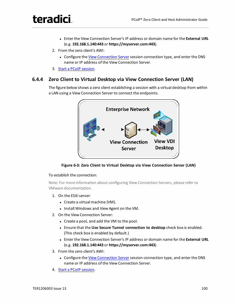
l Enter the View Connection Server's IP address or domain name for the External URL(e.g. 192.168.1.140:443 or https://myserver.com:443).
2. From the zero client's AWI:l Configure the View Connection Server session connection type, and enter the DNS
name or IP address of the View Connection Server.3. Start a PCoIP session.
6.4.4 Zero Client to Virtual Desktop via View Connection Server (LAN)The figure below shows a zero client establishing a session with a virtual desktop from withina LAN using a View Connection Server to connect the endpoints.
Figure 6-3: Zero Client to Virtual Desktop via View Connection Server (LAN)
To establish the connection:
Note: For more information about configuring View Connection Servers, please refer toVMware documentation.
1. On the ESXi server:l Create a virtual machine (VM).l Install Windows and ViewAgent on the VM.
2. On the View Connection Server:l Create a pool, and add the VM to the pool.l Ensure that theUse Secure Tunnel connection to desktop check box is enabled.
(This check box is enabled by default.)l Enter the View Connection Server's IP address or domain name for the External URL
(e.g. 192.168.1.140:443 or https://myserver.com:443).3. From the zero client's AWI:
l Configure the View Connection Server session connection type, and enter the DNSname or IP address of the View Connection Server.
4. Start a PCoIP session.
TER1206003 Issue 13 100
PCoIP® Zero Client and Host Administrator Guide
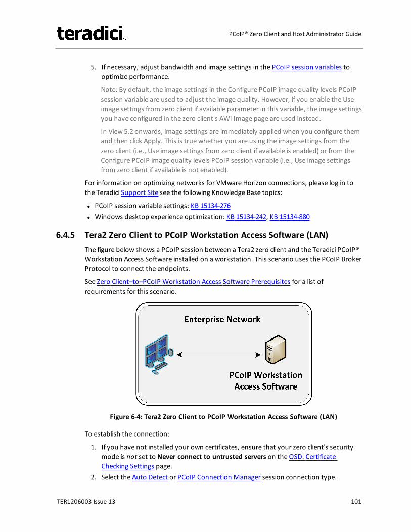
5. If necessary, adjust bandwidth and image settings in the PCoIP session variables tooptimize performance.
Note: By default, the image settings in the Configure PCoIP image quality levels PCoIPsession variable are used to adjust the image quality. However, if you enable the Useimage settings from zero client if available parameter in this variable, the image settingsyou have configured in the zero client's AWI Image page are used instead.
In View 5.2 onwards, image settings are immediately applied when you configure themand then click Apply. This is true whether you are using the image settings from thezero client (i.e., Use image settings from zero client if available is enabled) or from theConfigure PCoIP image quality levels PCoIP session variable (i.e., Use image settingsfrom zero client if available is not enabled).
For information on optimizing networks for VMware Horizon connections, please log in tothe Teradici Support Site see the following Knowledge Base topics:
l PCoIP session variable settings: KB 15134-276l Windows desktop experience optimization: KB 15134-242, KB 15134-880
6.4.5 Tera2 Zero Client to PCoIP Workstation Access Software (LAN)The figure below shows a PCoIP session between a Tera2 zero client and the Teradici PCoIP®Workstation Access Software installed on a workstation. This scenario uses the PCoIP BrokerProtocol to connect the endpoints.
See Zero Client–to–PCoIP Workstation Access Software Prerequisites for a list ofrequirements for this scenario.
Figure 6-4: Tera2 Zero Client to PCoIP Workstation Access Software (LAN)
To establish the connection:
1. If you have not installed your own certificates, ensure that your zero client's securitymode is not set to Never connect to untrusted servers on the OSD: CertificateChecking Settings page.
2. Select the Auto Detect or PCoIP Connection Manager session connection type.
TER1206003 Issue 13 101
PCoIP® Zero Client and Host Administrator Guide
3. Enter the fully-qualified computer name or IP address of the host workstation, andthen click OK.
4. Start a PCoIP session.
For more information about the Teradici PCoIP®Workstation Access Software, please log into the Teradici Support Site and see the following documentation:
l “Teradici PCoIP®Workstation Access Software User Guide" (TER1405004) in the TeradiciSupport Documentation Center. Instructions for creating and installing your owncertificates for the Teradici PCoIP®Workstation Access Software are also included in thisdocument.
l KB 15134-2055: Describes the firewall rules that are automatically created when theTeradici PCoIP®Workstation Access Software is installed.
6.5 Common Remote Access Scenarios
6.5.1 Connecting RemotelyPCoIP sessions between clients and hosts can operate in a wide area network (WAN) thattraverses the Internet. You can connect clients and hosts remotely using the following mainmethods:
l Configuring network address translation (NAT) devices at both ends to implement thenecessary IP address and port translation. This method applies only to Tera2 devices thatemploy UDP-encapsulated IPsec ESP encryption (firmware 4.1.0 or newer).
l Setting up a VPN to connect two trusted networks over an intermediate untrustednetwork.
l Using a security server/connection server pair to secure and broker the outside client tothe trusted inside network.
The scenarios listed below describe some common ways you can connect PCoIP endpointsremotely.
l Scenario 1: Connecting a zero client to a remote workstation card.l Scenario 2: Connecting a zero client to a remote workstation card over a hardware VPN.l Scenario 3: Using a third-party broker to connect a zero client to a remote workstation
card.l Scenario 4: Connecting a Tera2 Zero Client to the Teradici PCoIP®Workstation Access
Software.l Scenario 5: Connecting a Tera2 Zero Client to Amazon WorkSpaces.l Scenario 6: Using a View Security Server/View Connection Server pair to broker a
connection between a zero client and a remote workstation card.
TER1206003 Issue 13 102
PCoIP® Zero Client and Host Administrator Guide
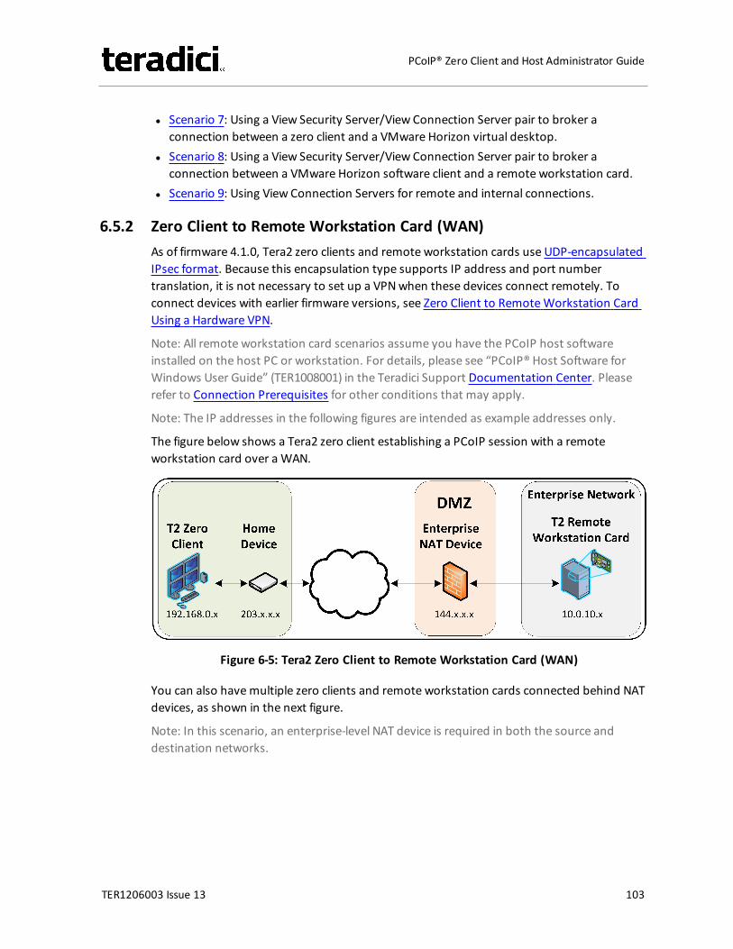
l Scenario 7: Using a View Security Server/View Connection Server pair to broker aconnection between a zero client and a VMware Horizon virtual desktop.
l Scenario 8: Using a View Security Server/View Connection Server pair to broker aconnection between a VMware Horizon software client and a remote workstation card.
l Scenario 9: Using View Connection Servers for remote and internal connections.
6.5.2 Zero Client to Remote Workstation Card (WAN)As of firmware 4.1.0, Tera2 zero clients and remote workstation cards use UDP-encapsulatedIPsec format. Because this encapsulation type supports IP address and port numbertranslation, it is not necessary to set up a VPNwhen these devices connect remotely. Toconnect devices with earlier firmware versions, see Zero Client to RemoteWorkstation CardUsing a Hardware VPN.
Note: All remote workstation card scenarios assume you have the PCoIP host softwareinstalled on the host PC or workstation. For details, please see “PCoIP® Host Software forWindows User Guide” (TER1008001) in the Teradici Support Documentation Center. Pleaserefer to Connection Prerequisites for other conditions that may apply.
Note: The IP addresses in the following figures are intended as example addresses only.
The figure below shows a Tera2 zero client establishing a PCoIP session with a remoteworkstation card over a WAN.
Figure 6-5: Tera2 Zero Client to Remote Workstation Card (WAN)
You can also havemultiple zero clients and remote workstation cards connected behind NATdevices, as shown in the next figure.
Note: In this scenario, an enterprise-level NAT device is required in both the source anddestination networks.
TER1206003 Issue 13 103
PCoIP® Zero Client and Host Administrator Guide
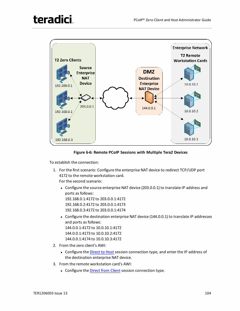
Figure 6-6: Remote PCoIP Sessions with Multiple Tera2 Devices
To establish the connection:
1. For the first scenario: Configure the enterprise NAT device to redirect TCP/UDP port4172 to the remote workstation card.For the second scenario:l Configure the source enterprise NAT device (203.0.0.1) to translate IP address and
ports as follows:192.168.0.1:4172 to 203.0.0.1:4172192.168.0.2:4172 to 203.0.0.1:4173192.168.0.3:4172 to 203.0.0.1:4174
l Configure the destination enterprise NAT device (144.0.0.1) to translate IP addressesand ports as follows:144.0.0.1:4172 to 10.0.10.1:4172144.0.0.1:4173 to 10.0.10.2:4172144.0.0.1:4174 to 10.0.10.3:4172
2. From the zero client's AWI:l Configure the Direct to Host session connection type, and enter the IP address of
the destination enterprise NAT device.3. From the remote workstation card's AWI:
l Configure the Direct from Client session connection type.
TER1206003 Issue 13 104
PCoIP® Zero Client and Host Administrator Guide
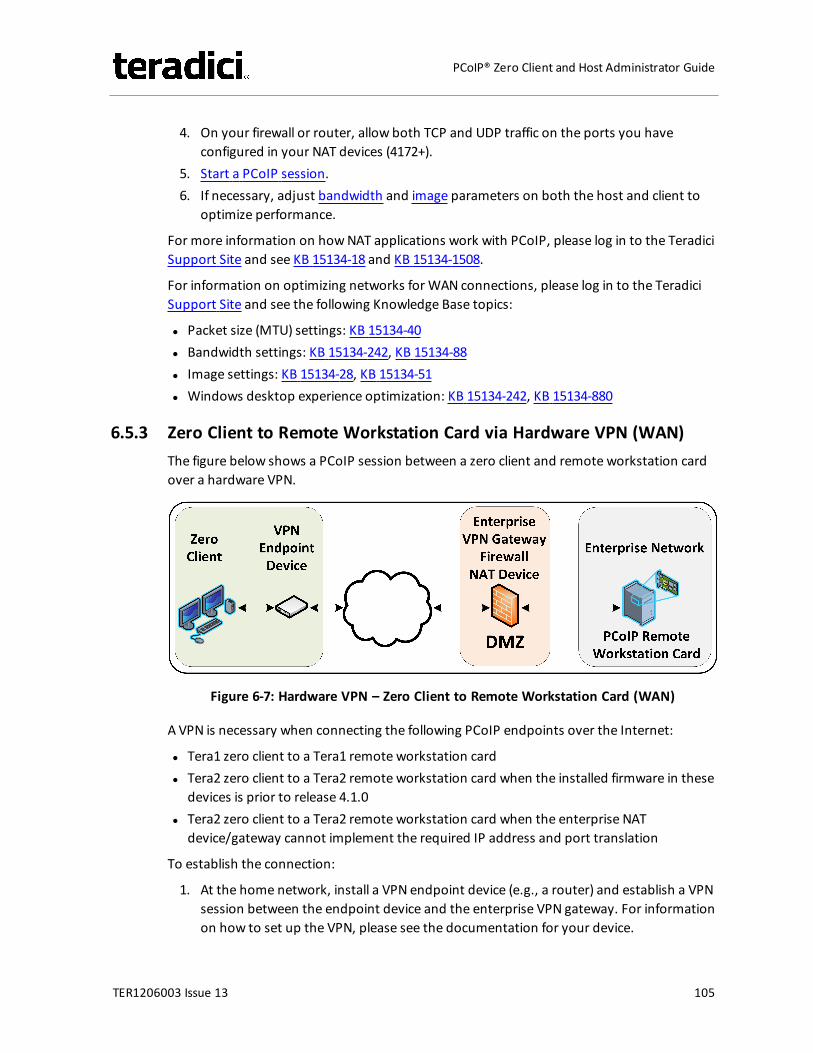
4. On your firewall or router, allow both TCP and UDP traffic on the ports you haveconfigured in your NAT devices (4172+).
5. Start a PCoIP session.6. If necessary, adjust bandwidth and image parameters on both the host and client to
optimize performance.
For more information on howNAT applications work with PCoIP, please log in to the TeradiciSupport Site and see KB 15134-18 and KB 15134-1508.
For information on optimizing networks for WAN connections, please log in to the TeradiciSupport Site and see the following Knowledge Base topics:
l Packet size (MTU) settings: KB 15134-40l Bandwidth settings: KB 15134-242, KB 15134-88l Image settings: KB 15134-28, KB 15134-51l Windows desktop experience optimization: KB 15134-242, KB 15134-880
6.5.3 Zero Client to Remote Workstation Card via Hardware VPN (WAN)The figure below shows a PCoIP session between a zero client and remote workstation cardover a hardware VPN.
Figure 6-7: Hardware VPN – Zero Client to Remote Workstation Card (WAN)
A VPN is necessary when connecting the following PCoIP endpoints over the Internet:
l Tera1 zero client to a Tera1 remote workstation cardl Tera2 zero client to a Tera2 remote workstation card when the installed firmware in these
devices is prior to release 4.1.0l Tera2 zero client to a Tera2 remote workstation card when the enterprise NAT
device/gateway cannot implement the required IP address and port translation
To establish the connection:
1. At the home network, install a VPN endpoint device (e.g., a router) and establish a VPNsession between the endpoint device and the enterprise VPN gateway. For informationon how to set up the VPN, please see the documentation for your device.
TER1206003 Issue 13 105
PCoIP® Zero Client and Host Administrator Guide
2. Configure the enterprise VPN gateway/firewall/NAT device to allow IPsec ESP traffic,and also traffic on UDP port 4172 for the PCoIP data stream and on TCP port 4172 forthe TCP handshake.
3. From the zero client's AWI:l Configure the Direct to Host session connection type, and enter the IP address of
the remote workstation card.l Configure the address of the home VPN endpoint device as the default gateway.l Set the packet MTU to be less than or equal to the largest size supported by the
VPN tunnel.4. From the remote workstation card's AWI:
l Configure the Direct from Client session connection type.l Set the packet MTU to be less than or equal to the largest size supported by the
VPN tunnel.5. Start a PCoIP session.6. If necessary, adjust bandwidth and image parameters on both the host and client to
optimize performance.
For information on optimizing networks for WAN connections, please log in to the TeradiciSupport Site and see the following Knowledge Base topics:
l Packet size (MTU) settings: KB 15134-40l Bandwidth settings: KB 15134-242, KB 15134-88l Image settings: KB 15134-28, KB 15134-51l Windows desktop experience optimization: KB 15134-242, KB 15134-880
6.5.4 Zero Client to Remote Workstation Card via 3rd Party Broker (WAN)The figure below shows a zero client establishing a PCoIP session with a remote workstationcard over a WANwith a 3rd party broker in the enterprise network acting as a connectionserver.
Note: All remote workstation card scenarios assume you have the PCoIP host softwareinstalled on the host PC or workstation. For details, please see “PCoIP® Host Software forWindows User Guide” (TER1008001) in the Teradici Support Documentation Center. Pleaserefer to Connection Prerequisites for other conditions that may apply.
TER1206003 Issue 13 106
PCoIP® Zero Client and Host Administrator Guide
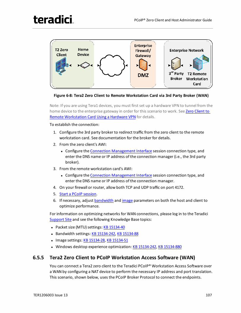
Figure 6-8: Tera2 Zero Client to Remote Workstation Card via 3rd Party Broker (WAN)
Note: If you are using Tera1 devices, you must first set up a hardware VPN to tunnel from thehome device to the enterprise gateway in order for this scenario to work. See Zero Client toRemoteWorkstation Card Using a Hardware VPN for details.
To establish the connection:
1. Configure the 3rd party broker to redirect traffic from the zero client to the remoteworkstation card. See documentation for the broker for details.
2. From the zero client's AWI:l Configure the Connection Management Interface session connection type, and
enter the DNS name or IP address of the connection manager (i.e., the 3rd partybroker).
3. From the remote workstation card's AWI:l Configure the Connection Management Interface session connection type, and
enter the DNS name or IP address of the connection manager.4. On your firewall or router, allow both TCP and UDP traffic on port 4172.5. Start a PCoIP session.6. If necessary, adjust bandwidth and image parameters on both the host and client to
optimize performance.
For information on optimizing networks for WAN connections, please log in to the TeradiciSupport Site and see the following Knowledge Base topics:
l Packet size (MTU) settings: KB 15134-40l Bandwidth settings: KB 15134-242, KB 15134-88l Image settings: KB 15134-28, KB 15134-51l Windows desktop experience optimization: KB 15134-242, KB 15134-880
6.5.5 Tera2 Zero Client to PCoIP Workstation Access Software (WAN)You can connect a Tera2 zero client to the Teradici PCoIP®Workstation Access Software overa WANby configuring a NAT device to perform the necessary IP address and port translation.This scenario, shown below, uses the PCoIP Broker Protocol to connect the endpoints.
TER1206003 Issue 13 107
PCoIP® Zero Client and Host Administrator Guide
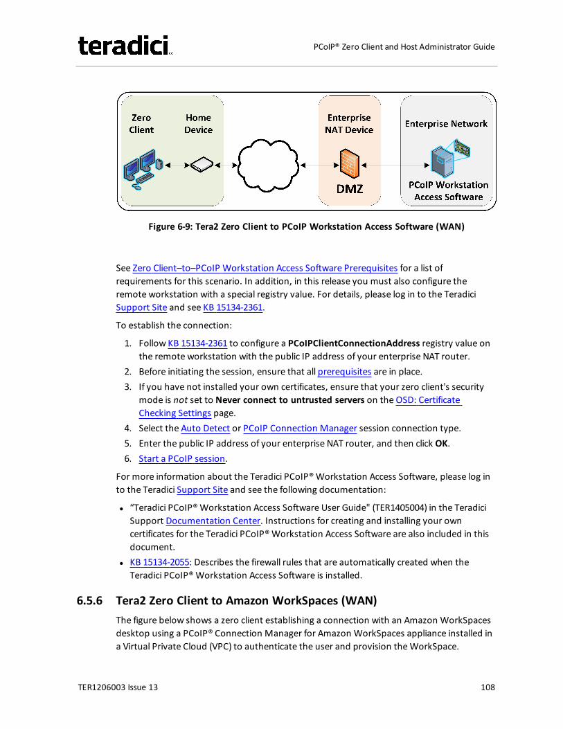
Figure 6-9: Tera2 Zero Client to PCoIP Workstation Access Software (WAN)
See Zero Client–to–PCoIP Workstation Access Software Prerequisites for a list ofrequirements for this scenario. In addition, in this release you must also configure theremote workstation with a special registry value. For details, please log in to the TeradiciSupport Site and see KB 15134-2361.
To establish the connection:
1. Follow KB 15134-2361 to configure a PCoIPClientConnectionAddress registry value onthe remote workstation with the public IP address of your enterprise NAT router.
2. Before initiating the session, ensure that all prerequisites are in place.3. If you have not installed your own certificates, ensure that your zero client's security
mode is not set to Never connect to untrusted servers on the OSD: CertificateChecking Settings page.
4. Select the Auto Detect or PCoIP Connection Manager session connection type.5. Enter the public IP address of your enterprise NAT router, and then click OK.6. Start a PCoIP session.
For more information about the Teradici PCoIP®Workstation Access Software, please log into the Teradici Support Site and see the following documentation:
l “Teradici PCoIP®Workstation Access Software User Guide" (TER1405004) in the TeradiciSupport Documentation Center. Instructions for creating and installing your owncertificates for the Teradici PCoIP®Workstation Access Software are also included in thisdocument.
l KB 15134-2055: Describes the firewall rules that are automatically created when theTeradici PCoIP®Workstation Access Software is installed.
6.5.6 Tera2 Zero Client to Amazon WorkSpaces (WAN)The figure below shows a zero client establishing a connection with an Amazon WorkSpacesdesktop using a PCoIP® Connection Manager for Amazon WorkSpaces appliance installed ina Virtual Private Cloud (VPC) to authenticate the user and provision theWorkSpace.
TER1206003 Issue 13 108
PCoIP® Zero Client and Host Administrator Guide
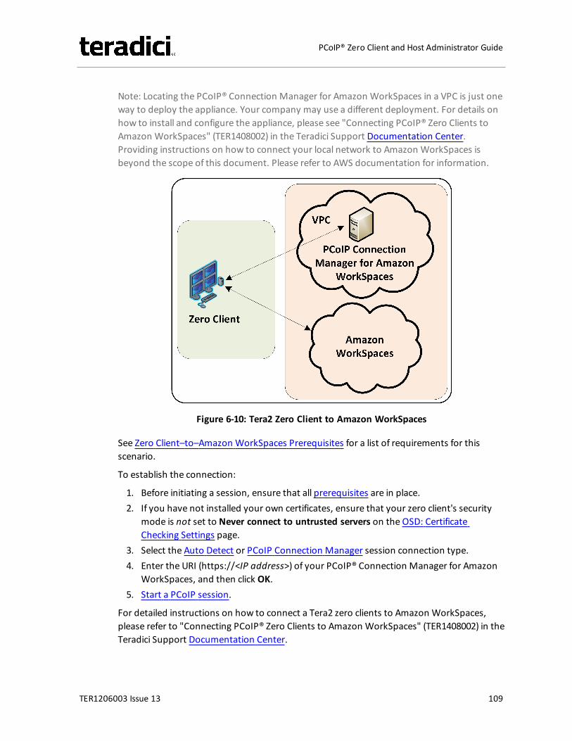
Note: Locating the PCoIP® Connection Manager for Amazon WorkSpaces in a VPC is just oneway to deploy the appliance. Your company may use a different deployment. For details onhow to install and configure the appliance, please see "Connecting PCoIP® Zero Clients toAmazon WorkSpaces" (TER1408002) in the Teradici Support Documentation Center.Providing instructions on how to connect your local network to Amazon WorkSpaces isbeyond the scope of this document. Please refer to AWS documentation for information.
Figure 6-10: Tera2 Zero Client to Amazon WorkSpaces
See Zero Client–to–Amazon WorkSpaces Prerequisites for a list of requirements for thisscenario.
To establish the connection:
1. Before initiating a session, ensure that all prerequisites are in place.2. If you have not installed your own certificates, ensure that your zero client's security
mode is not set to Never connect to untrusted servers on the OSD: CertificateChecking Settings page.
3. Select the Auto Detect or PCoIP Connection Manager session connection type.4. Enter the URI (https://<IP address>) of your PCoIP® Connection Manager for Amazon
WorkSpaces, and then click OK.5. Start a PCoIP session.
For detailed instructions on how to connect a Tera2 zero clients to Amazon WorkSpaces,please refer to "Connecting PCoIP® Zero Clients to Amazon WorkSpaces" (TER1408002) in theTeradici Support Documentation Center.
TER1206003 Issue 13 109
PCoIP® Zero Client and Host Administrator Guide
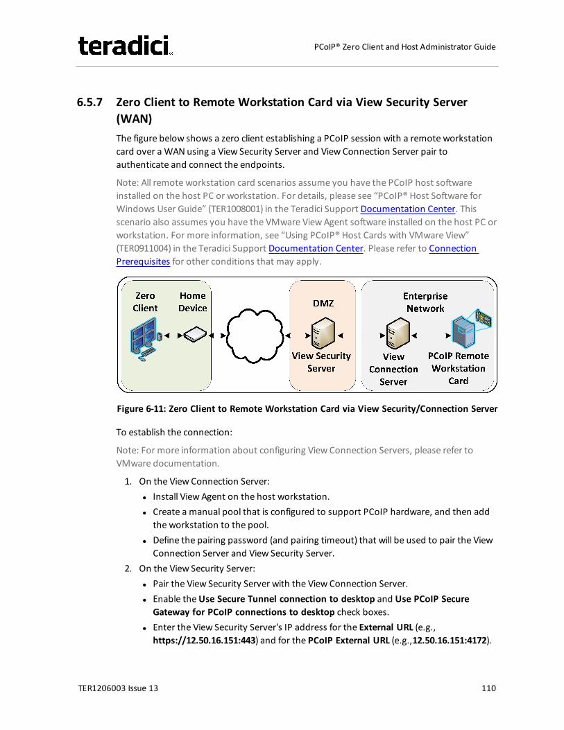
6.5.7 Zero Client to Remote Workstation Card via View Security Server(WAN)The figure below shows a zero client establishing a PCoIP session with a remote workstationcard over a WANusing a View Security Server and View Connection Server pair toauthenticate and connect the endpoints.
Note: All remote workstation card scenarios assume you have the PCoIP host softwareinstalled on the host PC or workstation. For details, please see “PCoIP® Host Software forWindows User Guide” (TER1008001) in the Teradici Support Documentation Center. Thisscenario also assumes you have the VMware ViewAgent software installed on the host PC orworkstation. For more information, see “Using PCoIP® Host Cards with VMware View”(TER0911004) in the Teradici Support Documentation Center. Please refer to ConnectionPrerequisites for other conditions that may apply.
Figure 6-11: Zero Client to Remote Workstation Card via View Security/Connection Server
To establish the connection:
Note: For more information about configuring View Connection Servers, please refer toVMware documentation.
1. On the View Connection Server:l Install View Agent on the host workstation.l Create a manual pool that is configured to support PCoIP hardware, and then add
the workstation to the pool.l Define the pairing password (and pairing timeout) that will be used to pair the View
Connection Server and View Security Server.2. On the View Security Server:
l Pair the View Security Server with the View Connection Server.l Enable theUse Secure Tunnel connection to desktop and Use PCoIP Secure
Gateway for PCoIP connections to desktop check boxes.l Enter the View Security Server's IP address for the External URL (e.g.,
https://12.50.16.151:443) and for the PCoIP External URL (e.g.,12.50.16.151:4172).
TER1206003 Issue 13 110
PCoIP® Zero Client and Host Administrator Guide
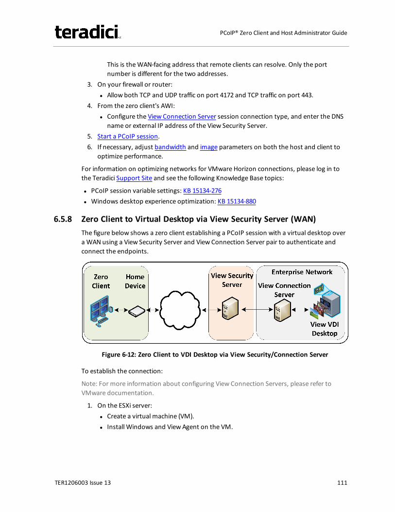
This is theWAN-facing address that remote clients can resolve. Only the portnumber is different for the two addresses.
3. On your firewall or router:l Allow both TCP and UDP traffic on port 4172 and TCP traffic on port 443.
4. From the zero client's AWI:l Configure the View Connection Server session connection type, and enter the DNS
name or external IP address of the View Security Server.5. Start a PCoIP session.6. If necessary, adjust bandwidth and image parameters on both the host and client to
optimize performance.
For information on optimizing networks for VMware Horizon connections, please log in tothe Teradici Support Site and see the following Knowledge Base topics:
l PCoIP session variable settings: KB 15134-276l Windows desktop experience optimization: KB 15134-880
6.5.8 Zero Client to Virtual Desktop via View Security Server (WAN)The figure below shows a zero client establishing a PCoIP session with a virtual desktop overa WANusing a View Security Server and View Connection Server pair to authenticate andconnect the endpoints.
Figure 6-12: Zero Client to VDI Desktop via View Security/Connection Server
To establish the connection:
Note: For more information about configuring View Connection Servers, please refer toVMware documentation.
1. On the ESXi server:l Create a virtual machine (VM).l Install Windows and ViewAgent on the VM.
TER1206003 Issue 13 111
PCoIP® Zero Client and Host Administrator Guide
2. On the View Connection Server:l Create a pool, and add the VM to the pool.l Define the pairing password (and pairing timeout) that will be used to pair the View
Connection Server and View Security Server.3. On the View Security Server:
l Pair the View Security Server with the View Connection Server.l Enable theUse Secure Tunnel connection to desktop and Use PCoIP Secure
Gateway for PCoIP connections to desktop check boxes.l Enter the View Security Server's IP address for the External URL (e.g.,
https://12.50.16.151:443) and for the PCoIP External URL (e.g.,12.50.16.151:4172).This is theWAN-facing address that remote clients can resolve. Only the portnumber is different for the two addresses.
4. On your firewall or router:l Allow both TCP and UDP traffic on port 4172, and TCP traffic on port 443.
5. From the zero client's AWI:l Configure the View Connection Server session connection type, and enter the DNS
name or externalWAN IP address of the View Security Server.6. Start a PCoIP session.7. If necessary, adjust bandwidth and image settings in the PCoIP session variables to
optimize performance.
Note: By default, the image settings in the Configure PCoIP image quality levels PCoIPsession variable are used to adjust the image quality. However, if you enable the Useimage settings from zero client if available parameter in this variable, the image settingsyou have configured in the zero client's AWI Image page are used instead.
In View 5.2 onwards, image settings are immediately applied when you configure themand then click Apply. This is true whether you are using the image settings from thezero client (i.e., Use image settings from zero client if available is enabled) or from theConfigure PCoIP image quality levels PCoIP session variable (i.e., Use image settingsfrom zero client if available is not enabled).
For information on optimizing networks for VMware Horizon connections, please log in tothe Teradici Support Site see the following Knowledge Base topics:
l PCoIP session variable settings: KB 15134-276l Windows desktop experience optimization: KB 15134-242, KB 15134-880
6.5.9 VMware Horizon Software Client to Remote Workstation Card viaView Security Server (WAN)The figure below shows a a VMware Horizon software client establishing a PCoIP session witha remote workstation card over a WANusing a View Security Server and View ConnectionServer pair to authenticate and connect the endpoints.
TER1206003 Issue 13 112
PCoIP® Zero Client and Host Administrator Guide
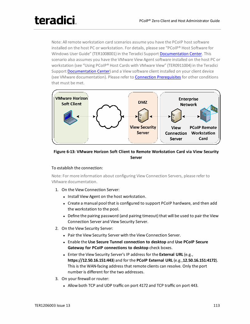
Note: All remote workstation card scenarios assume you have the PCoIP host softwareinstalled on the host PC or workstation. For details, please see “PCoIP® Host Software forWindows User Guide” (TER1008001) in the Teradici Support Documentation Center. Thisscenario also assumes you have the VMware ViewAgent software installed on the host PC orworkstation (see “Using PCoIP® Host Cards with VMware View” (TER0911004) in the TeradiciSupport Documentation Center) and a View software client installed on your client device(see VMware documentation). Please refer to Connection Prerequisites for other conditionsthat must bemet.
Figure 6-13: VMware Horizon Soft Client to Remote Workstation Card via View SecurityServer
To establish the connection:
Note: For more information about configuring View Connection Servers, please refer toVMware documentation.
1. On the View Connection Server:l Install View Agent on the host workstation.l Create a manual pool that is configured to support PCoIP hardware, and then add
the workstation to the pool.l Define the pairing password (and pairing timeout) that will be used to pair the View
Connection Server and View Security Server.2. On the View Security Server:
l Pair the View Security Server with the View Connection Server.l Enable theUse Secure Tunnel connection to desktop and Use PCoIP Secure
Gateway for PCoIP connections to desktop check boxes.l Enter the View Security Server's IP address for the External URL (e.g.,
https://12.50.16.151:443) and for the PCoIP External URL (e.g.,12.50.16.151:4172).This is theWAN-facing address that remote clients can resolve. Only the portnumber is different for the two addresses.
3. On your firewall or router:l Allow both TCP and UDP traffic on port 4172 and TCP traffic on port 443.
TER1206003 Issue 13 113
PCoIP® Zero Client and Host Administrator Guide
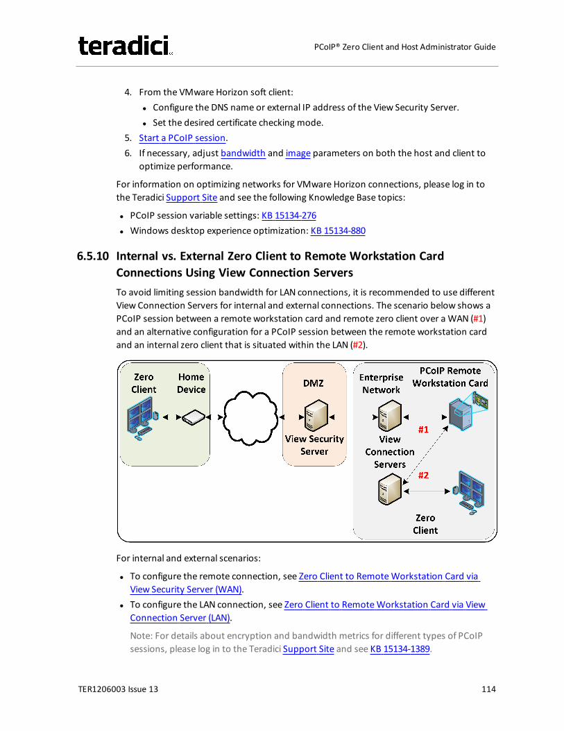
4. From the VMware Horizon soft client:l Configure the DNS name or external IP address of the View Security Server.l Set the desired certificate checking mode.
5. Start a PCoIP session.6. If necessary, adjust bandwidth and image parameters on both the host and client to
optimize performance.
For information on optimizing networks for VMware Horizon connections, please log in tothe Teradici Support Site and see the following Knowledge Base topics:
l PCoIP session variable settings: KB 15134-276l Windows desktop experience optimization: KB 15134-880
6.5.10 Internal vs. External Zero Client to Remote Workstation CardConnections Using View Connection ServersTo avoid limiting session bandwidth for LAN connections, it is recommended to use differentView Connection Servers for internal and external connections. The scenario below shows aPCoIP session between a remote workstation card and remote zero client over a WAN (#1)and an alternative configuration for a PCoIP session between the remote workstation cardand an internal zero client that is situated within the LAN (#2).
For internal and external scenarios:
l To configure the remote connection, see Zero Client to RemoteWorkstation Card viaView Security Server (WAN).
l To configure the LAN connection, see Zero Client to RemoteWorkstation Card via ViewConnection Server (LAN).
Note: For details about encryption and bandwidth metrics for different types of PCoIPsessions, please log in to the Teradici Support Site and see KB 15134-1389.
TER1206003 Issue 13 114
PCoIP® Zero Client and Host Administrator Guide
6.6 Security Considerations
6.6.1 PCoIP Zero Client Security OverviewPCoIP zero clients are ultra-secure, easy to manage devices that offer a rich user experience.Based on the TERA chipset by Teradici, they are available in a variety of form factors from anumber of trusted OEMs. For example, PCoIP zero clients can be standalone desktopdevices, integrated monitors, touch screen displays, and IP phones. With embeddedhardware support for PCoIP and no local storage, they are themost trusted client whereversecurity and performance are critical.
Data Control
When control and lockdown of sensitive data are a primary objective, PCoIP zero clientsenable an environment where no application data ever leaves the data center. The virtualmachine sends only encrypted PCoIP data to the client. PCoIP zero clients have no localstorage, and no sensitive application data is ever processed or stored on the client.
Zero clients also havemany security-related settings that are frequently used in high securitydeployments.
User Authentication
PCoIP zero clients support a number of third-party, hardware-based, user authenticationmethods including the following:
l SIPR hardware tokensl Common Access Card (CAC) and Personal Identity Verfication (PIV) smart cardsl SafeNet eTokenl RSA SecurIDl Proximity cards (Imprivata)
For a complete list of supported authentication methods, see KB 15134-299 in the TeradiciSupport Site.
Encryption
PCoIP zero clients support the following encryption types.
Session negotiation security:
l TLS 1.0 with AES-128-CBC-SHAl TLS 1.0 with AES-256-CBC-SHAl Suite B (in hardware host environments only)
Session security:
TER1206003 Issue 13 115
PCoIP® Zero Client and Host Administrator Guide
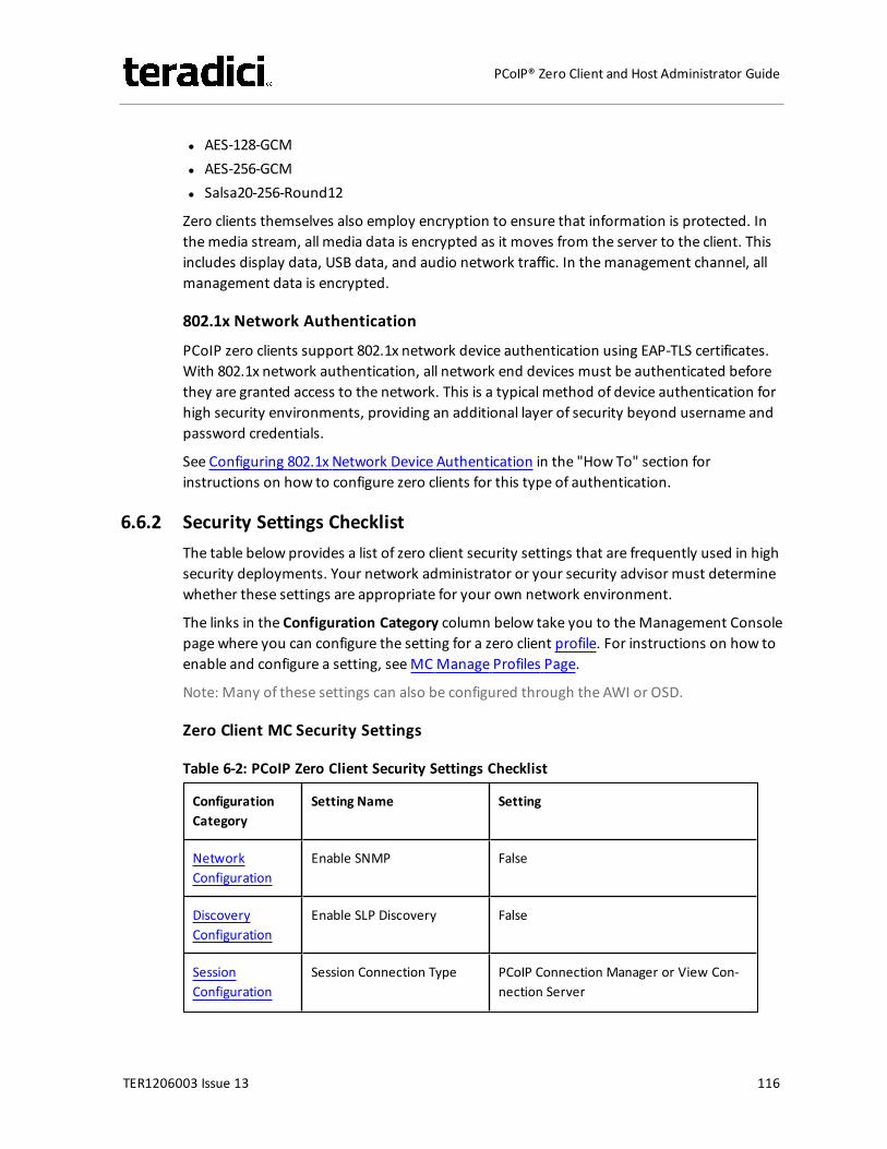
l AES-128-GCMl AES-256-GCMl Salsa20-256-Round12
Zero clients themselves also employ encryption to ensure that information is protected. Inthemedia stream, all media data is encrypted as it moves from the server to the client. Thisincludes display data, USB data, and audio network traffic. In themanagement channel, allmanagement data is encrypted.
802.1x Network Authentication
PCoIP zero clients support 802.1x network device authentication using EAP-TLS certificates.With 802.1x network authentication, all network end devices must be authenticated beforethey are granted access to the network. This is a typical method of device authentication forhigh security environments, providing an additional layer of security beyond username andpassword credentials.
See Configuring 802.1x Network Device Authentication in the "How To" section forinstructions on how to configure zero clients for this type of authentication.
6.6.2 Security Settings ChecklistThe table below provides a list of zero client security settings that are frequently used in highsecurity deployments. Your network administrator or your security advisor must determinewhether these settings are appropriate for your own network environment.
The links in the Configuration Category column below take you to theManagement Consolepage where you can configure the setting for a zero client profile. For instructions on how toenable and configure a setting, seeMCManage Profiles Page.
Note: Many of these settings can also be configured through the AWI or OSD.
Zero Client MC Security Settings
Table 6-2: PCoIP Zero Client Security Settings Checklist
ConfigurationCategory
Setting Name Setting
NetworkConfiguration
Enable SNMP False
DiscoveryConfiguration
Enable SLP Discovery False
SessionConfiguration
Session Connection Type PCoIP Connection Manager or View Con-nection Server
TER1206003 Issue 13 116
PCoIP® Zero Client and Host Administrator Guide
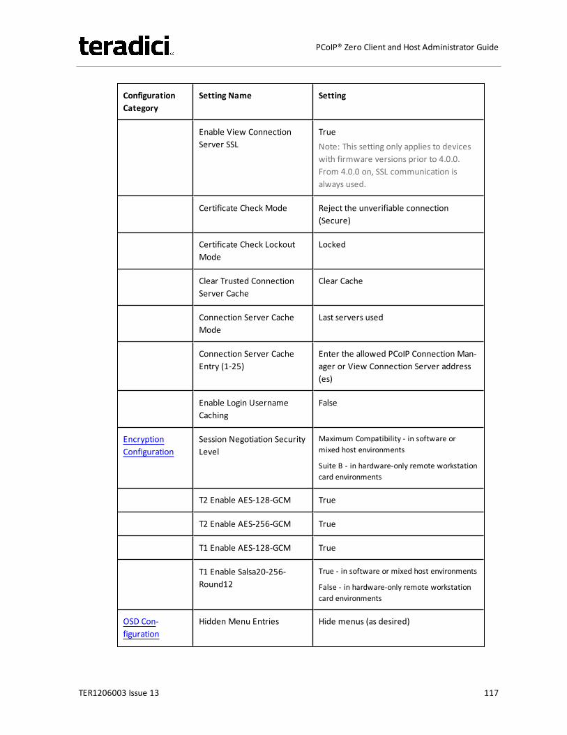
ConfigurationCategory
Setting Name Setting
Enable View ConnectionServer SSL
TrueNote: This setting only applies to deviceswith firmware versions prior to 4.0.0.From 4.0.0 on, SSL communication isalways used.
Certificate Check Mode Reject the unverifiable connection(Secure)
Certificate Check LockoutMode
Locked
Clear Trusted ConnectionServer Cache
Clear Cache
Connection Server CacheMode
Last servers used
Connection Server CacheEntry (1-25)
Enter the allowed PCoIP Connection Man-ager or View Connection Server address(es)
Enable Login UsernameCaching
False
EncryptionConfiguration
Session Negotiation SecurityLevel
Maximum Compatibility - in software ormixed host environments
Suite B - in hardware-only remote workstationcard environments
T2 Enable AES-128-GCM True
T2 Enable AES-256-GCM True
T1 Enable AES-128-GCM True
T1 Enable Salsa20-256-Round12
True - in software or mixed host environments
False - in hardware-only remote workstationcard environments
OSD Con-figuration
Hidden Menu Entries Hide menus (as desired)
TER1206003 Issue 13 117
PCoIP® Zero Client and Host Administrator Guide
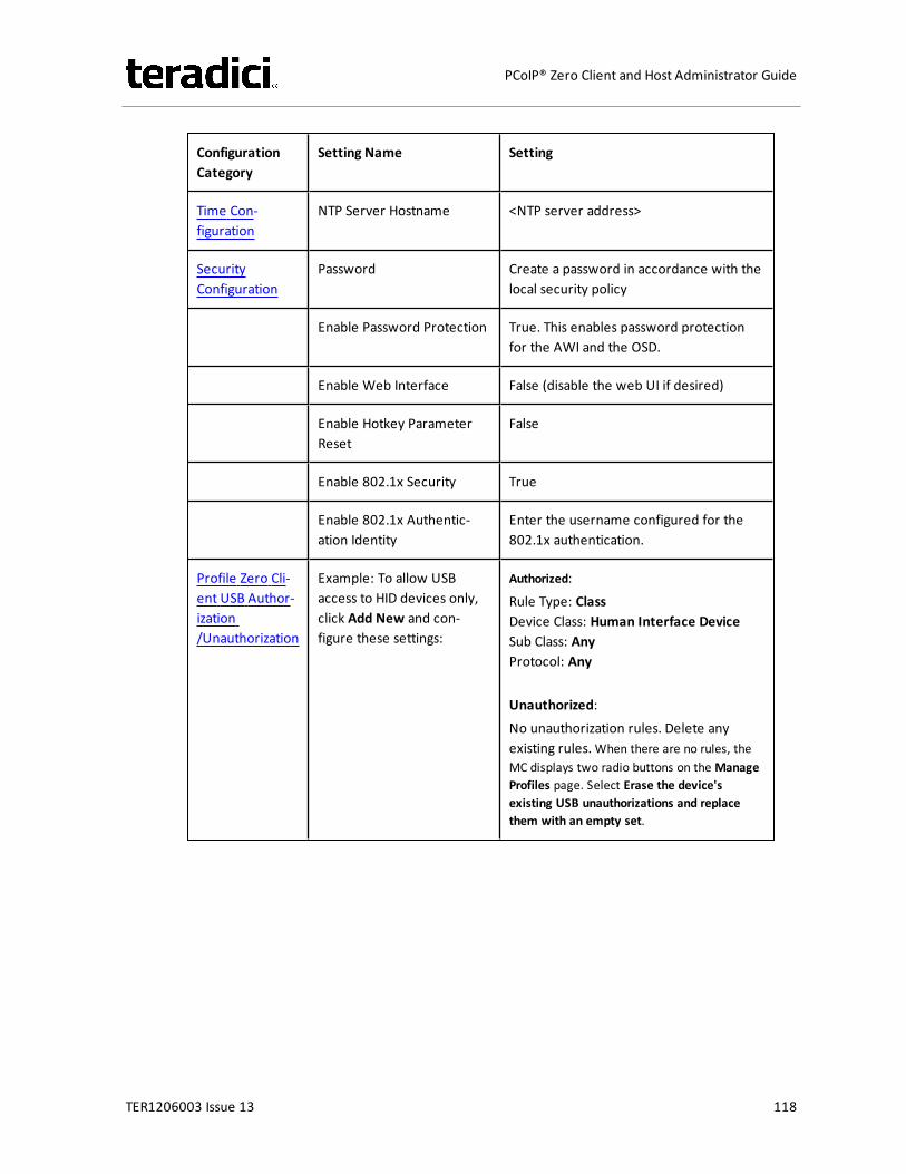
ConfigurationCategory
Setting Name Setting
Time Con-figuration
NTP Server Hostname <NTP server address>
SecurityConfiguration
Password Create a password in accordance with thelocal security policy
Enable Password Protection True. This enables password protectionfor the AWI and the OSD.
Enable Web Interface False (disable the web UI if desired)
Enable Hotkey ParameterReset
False
Enable 802.1x Security True
Enable 802.1x Authentic-ation Identity
Enter the username configured for the802.1x authentication.
Profile Zero Cli-ent USB Author-ization/Unauthorization
Example: To allow USBaccess to HID devices only,click Add New and con-figure these settings:
Authorized:Rule Type: ClassDevice Class: Human Interface DeviceSub Class: AnyProtocol: Any
Unauthorized:No unauthorization rules. Delete anyexisting rules.When there are no rules, theMC displays two radio buttons on the ManageProfiles page. Select Erase the device'sexisting USB unauthorizations and replacethem with an empty set.
TER1206003 Issue 13 118
PCoIP® Zero Client and Host Administrator Guide
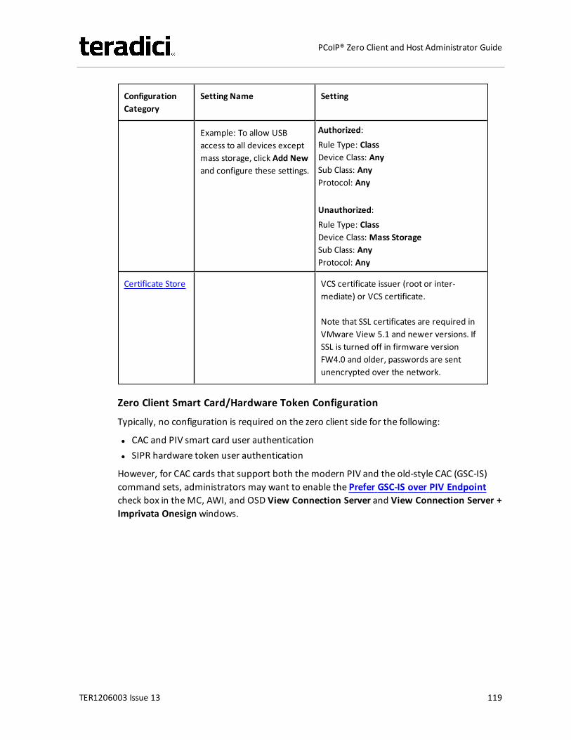
ConfigurationCategory
Setting Name Setting
Example: To allow USBaccess to all devices exceptmass storage, click Add Newand configure these settings.
Authorized:Rule Type: ClassDevice Class: AnySub Class: AnyProtocol: Any
Unauthorized:Rule Type: ClassDevice Class: Mass StorageSub Class: AnyProtocol: Any
Certificate Store VCS certificate issuer (root or inter-mediate) or VCS certificate.
Note that SSL certificates are required inVMware View 5.1 and newer versions. IfSSL is turned off in firmware versionFW4.0 and older, passwords are sentunencrypted over the network.
Zero Client Smart Card/Hardware Token Configuration
Typically, no configuration is required on the zero client side for the following:
l CAC and PIV smart card user authenticationl SIPR hardware token user authentication
However, for CAC cards that support both themodern PIV and the old-style CAC (GSC-IS)command sets, administrators may want to enable the Prefer GSC-IS over PIV Endpointcheck box in theMC, AWI, and OSD View Connection Server and View Connection Server +Imprivata Onesignwindows.
TER1206003 Issue 13 119
PCoIP® Zero Client and Host Administrator Guide
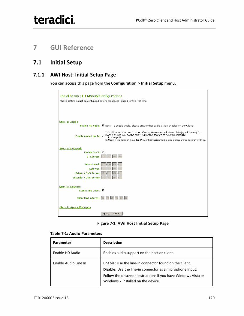
7 GUI Reference
7.1 Initial Setup
7.1.1 AWI Host: Initial Setup PageYou can access this page from the Configuration > Initial Setupmenu.
Figure 7-1: AWI Host Initial Setup Page
Table 7-1: Audio Parameters
Parameter Description
Enable HD Audio Enables audio support on the host or client.
Enable Audio Line In Enable: Use the line-in connector found on the client.Disable: Use the line-in connector as a microphone input.Follow the onscreen instructions if you have Windows Vista orWindows 7 installed on the device.
TER1206003 Issue 13 120
PCoIP® Zero Client and Host Administrator Guide
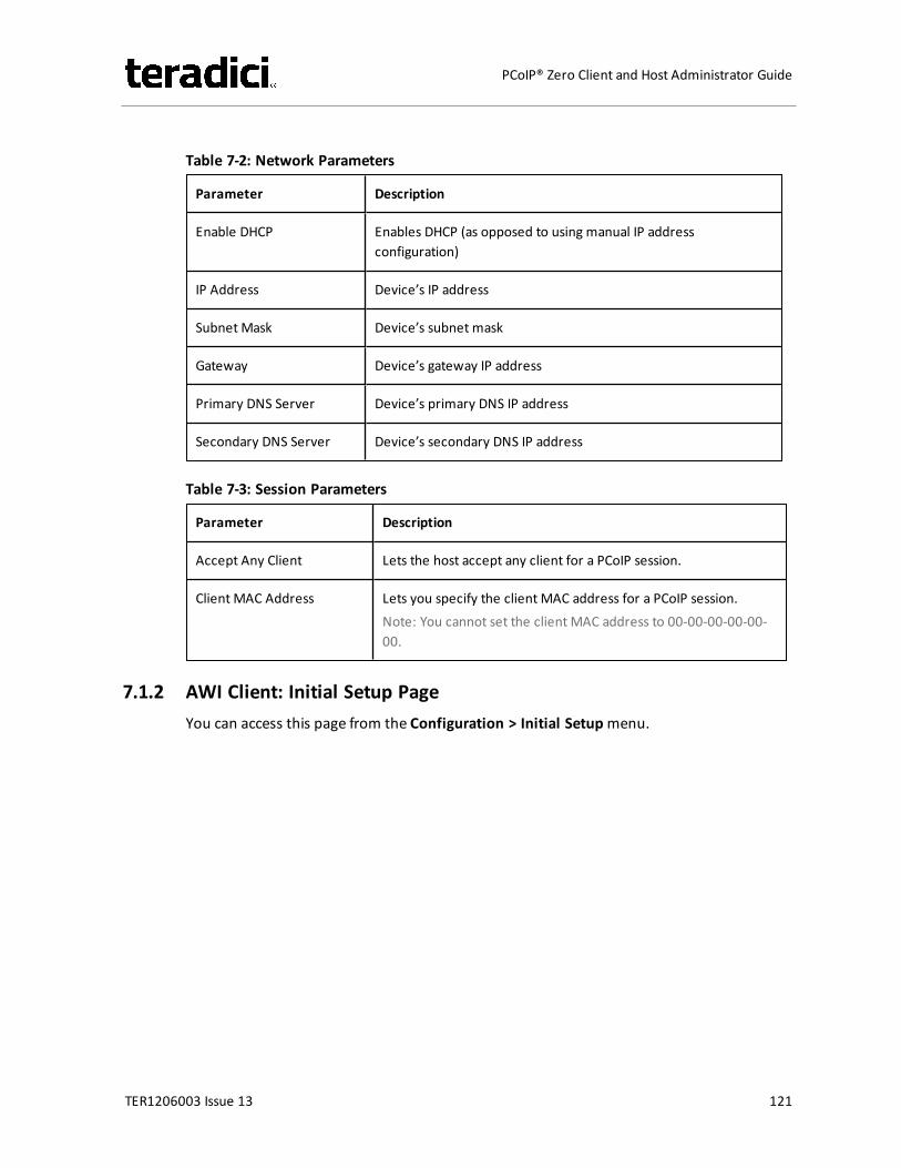
Table 7-2: Network Parameters
Parameter Description
Enable DHCP Enables DHCP (as opposed to using manual IP addressconfiguration)
IP Address Device’s IP address
Subnet Mask Device’s subnet mask
Gateway Device’s gateway IP address
Primary DNS Server Device’s primary DNS IP address
Secondary DNS Server Device’s secondary DNS IP address
Table 7-3: Session Parameters
Parameter Description
Accept Any Client Lets the host accept any client for a PCoIP session.
Client MAC Address Lets you specify the client MAC address for a PCoIP session.Note: You cannot set the client MAC address to 00-00-00-00-00-00.
7.1.2 AWI Client: Initial Setup PageYou can access this page from the Configuration > Initial Setupmenu.
TER1206003 Issue 13 121
PCoIP® Zero Client and Host Administrator Guide
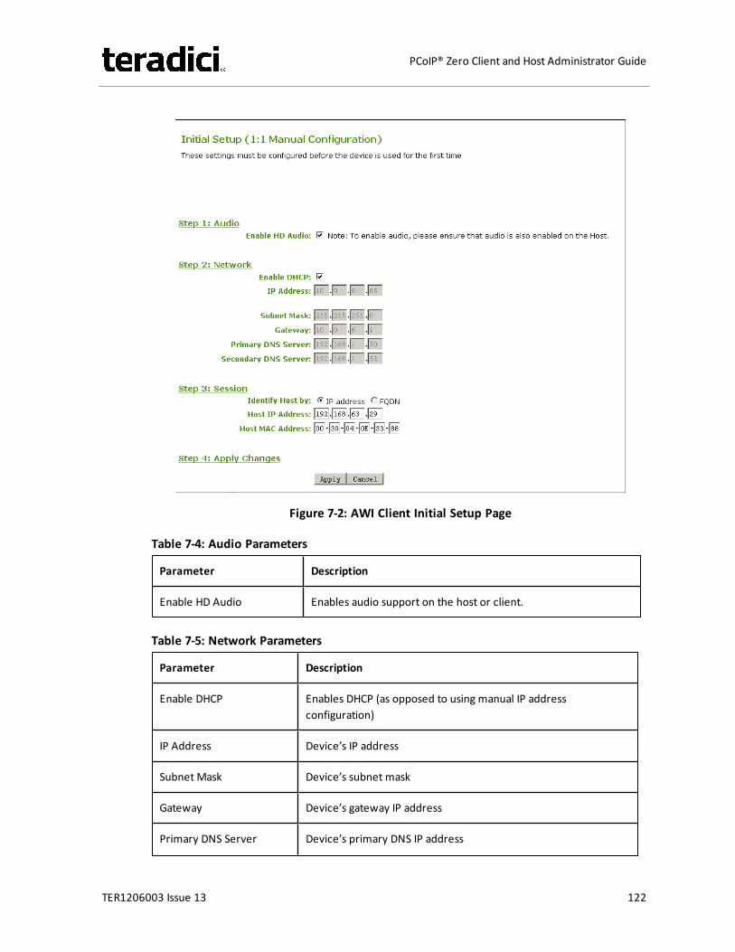
Figure 7-2: AWI Client Initial Setup Page
Table 7-4: Audio Parameters
Parameter Description
Enable HD Audio Enables audio support on the host or client.
Table 7-5: Network Parameters
Parameter Description
Enable DHCP Enables DHCP (as opposed to using manual IP addressconfiguration)
IP Address Device’s IP address
Subnet Mask Device’s subnet mask
Gateway Device’s gateway IP address
Primary DNS Server Device’s primary DNS IP address
TER1206003 Issue 13 122
PCoIP® Zero Client and Host Administrator Guide
Parameter Description
Secondary DNS Server Device’s secondary DNS IP address
Table 7-6: Session Parameters
Parameter Description
Identify Host By Specifies the host identify method
Host IP Address Specifies the host IP address
Host MAC Address Specifies the host MAC address.You can set the host MAC address to 00-00-00-00-00-00 toignore this field when a session starts.
Note: When host discovery or connection management is configured on the client, youcannot modify the client session parameters. Amessage appears on the Initial Setup Clientpage instead of the session parameters.
7.2 Configuring the Network
7.2.1 MC: Network SettingsThe settings on this page let you configure a profile with the Dynamic Host ConfigurationProtocol (DHCP), Maximum Transmission Unit (MTU), and Simple Network ManagmentProtocol parameters.
Note: To enable a property in theMC, click the Set in Profile check box and configure thefields as indicated. After you update the properties on this page, click Save to save yourchanges.
TER1206003 Issue 13 123
PCoIP® Zero Client and Host Administrator Guide
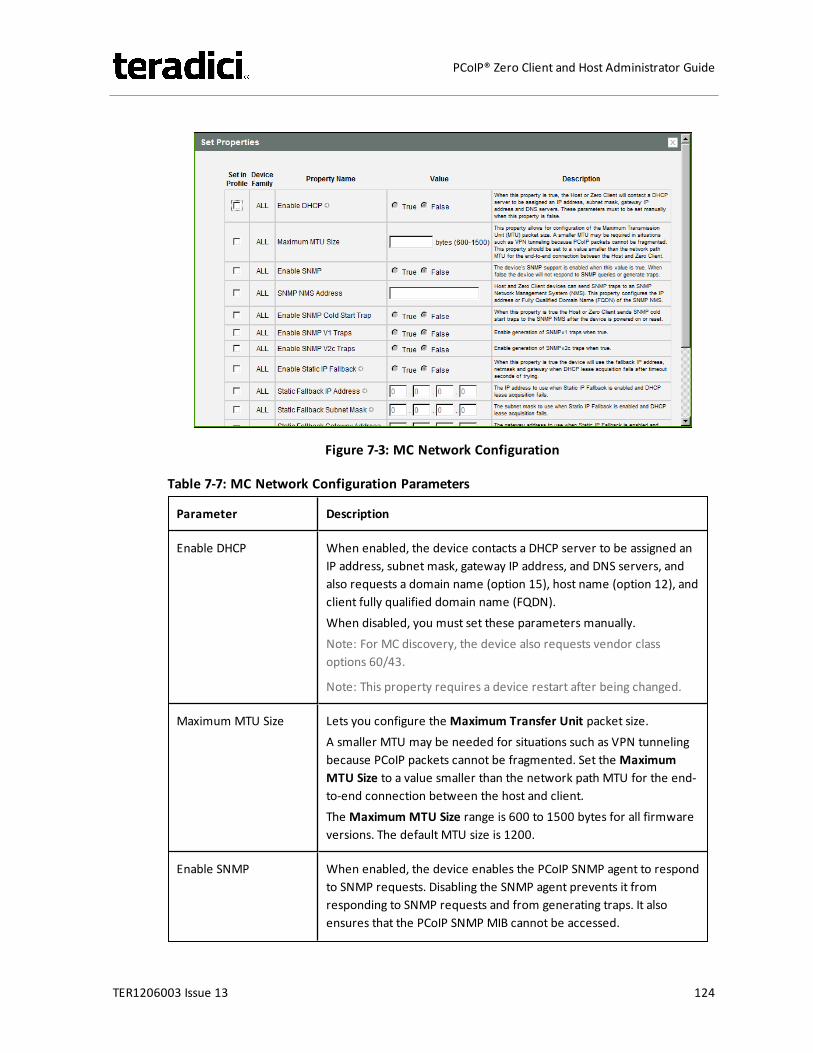
Figure 7-3: MC Network Configuration
Table 7-7: MC Network Configuration Parameters
Parameter Description
Enable DHCP When enabled, the device contacts a DHCP server to be assigned anIP address, subnet mask, gateway IP address, and DNS servers, andalso requests a domain name (option 15), host name (option 12), andclient fully qualified domain name (FQDN).When disabled, you must set these parameters manually.Note: For MC discovery, the device also requests vendor classoptions 60/43.
Note: This property requires a device restart after being changed.
Maximum MTU Size Lets you configure the Maximum Transfer Unit packet size.A smaller MTU may be needed for situations such as VPN tunnelingbecause PCoIP packets cannot be fragmented. Set the MaximumMTU Size to a value smaller than the network path MTU for the end-to-end connection between the host and client.The Maximum MTU Size range is 600 to 1500 bytes for all firmwareversions. The default MTU size is 1200.
Enable SNMP When enabled, the device enables the PCoIP SNMP agent to respondto SNMP requests. Disabling the SNMP agent prevents it fromresponding to SNMP requests and from generating traps. It alsoensures that the PCoIP SNMP MIB cannot be accessed.
TER1206003 Issue 13 124
PCoIP® Zero Client and Host Administrator Guide
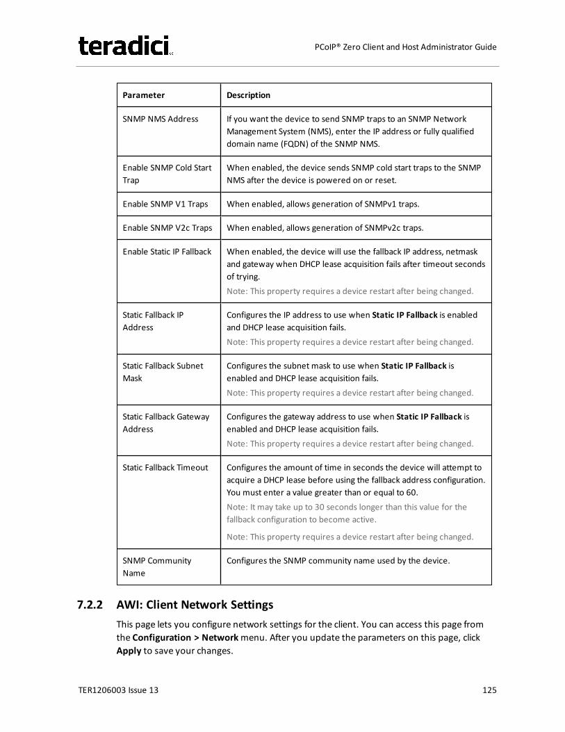
Parameter Description
SNMP NMS Address If you want the device to send SNMP traps to an SNMP NetworkManagement System (NMS), enter the IP address or fully qualifieddomain name (FQDN) of the SNMP NMS.
Enable SNMP Cold StartTrap
When enabled, the device sends SNMP cold start traps to the SNMPNMS after the device is powered on or reset.
Enable SNMP V1 Traps When enabled, allows generation of SNMPv1 traps.
Enable SNMP V2c Traps When enabled, allows generation of SNMPv2c traps.
Enable Static IP Fallback When enabled, the device will use the fallback IP address, netmaskand gateway when DHCP lease acquisition fails after timeout secondsof trying.Note: This property requires a device restart after being changed.
Static Fallback IPAddress
Configures the IP address to use when Static IP Fallback is enabledand DHCP lease acquisition fails.Note: This property requires a device restart after being changed.
Static Fallback SubnetMask
Configures the subnet mask to use when Static IP Fallback isenabled and DHCP lease acquisition fails.Note: This property requires a device restart after being changed.
Static Fallback GatewayAddress
Configures the gateway address to use when Static IP Fallback isenabled and DHCP lease acquisition fails.Note: This property requires a device restart after being changed.
Static Fallback Timeout Configures the amount of time in seconds the device will attempt toacquire a DHCP lease before using the fallback address configuration.You must enter a value greater than or equal to 60.Note: It may take up to 30 seconds longer than this value for thefallback configuration to become active.
Note: This property requires a device restart after being changed.
SNMP CommunityName
Configures the SNMP community name used by the device.
7.2.2 AWI: Client Network SettingsThis page lets you configure network settings for the client. You can access this page fromthe Configuration > Networkmenu. After you update the parameters on this page, clickApply to save your changes.
TER1206003 Issue 13 125
PCoIP® Zero Client and Host Administrator Guide
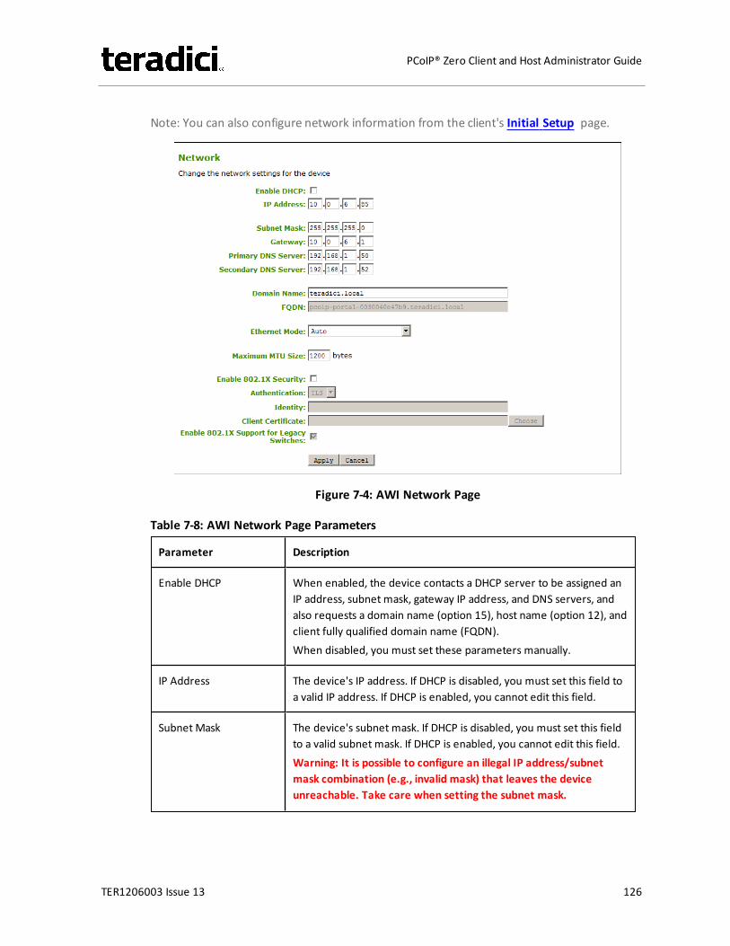
Note: You can also configure network information from the client's Initial Setup page.
Figure 7-4: AWI Network Page
Table 7-8: AWI Network Page Parameters
Parameter Description
Enable DHCP When enabled, the device contacts a DHCP server to be assigned anIP address, subnet mask, gateway IP address, and DNS servers, andalso requests a domain name (option 15), host name (option 12), andclient fully qualified domain name (FQDN).When disabled, you must set these parameters manually.
IP Address The device's IP address. If DHCP is disabled, you must set this field toa valid IP address. If DHCP is enabled, you cannot edit this field.
Subnet Mask The device's subnet mask. If DHCP is disabled, you must set this fieldto a valid subnet mask. If DHCP is enabled, you cannot edit this field.Warning: It is possible to configure an illegal IP address/subnetmask combination (e.g., invalid mask) that leaves the deviceunreachable. Take care when setting the subnet mask.
TER1206003 Issue 13 126
PCoIP® Zero Client and Host Administrator Guide

Parameter Description
Gateway The device's gateway IP address. If DHCP is disabled, this field isrequired. If DHCP is enabled, you cannot edit this field.
Primary DNS Server The device's primary DNS IP address. This field is optional. If the DNSserver IP address is configured when using a connection manager,the connection manager address may be set as an FQDN instead ofan IP address.
Secondary DNS Server The device's secondary DNS IP address. This field is optional. If theDNS server IP address is configured when using a connectionmanager, the connection manager address may be set as an FQDNinstead of an IP address.
Domain Name The domain named of the device (e.g., "domain.local"). This field isoptional.
FQDN The fully qualified domain name for the device. The default is pcoip-host-<MAC> or pcoip-portal-<MAC> where <MAC> is the device'sMAC address. If used, the domain name is appended (for example,pcoip-host-<MAC>.domain.local). This field is read-only on this page.Note: To use the FQDN feature, the DNS server with DHCP option 81must be available and properly configured.
Ethernet Mode Lets you configure the Ethernet mode of the device as follows:l Autol 100 Mbps Full-Duplexl 10 Mbps Full-DuplexWhen you choose 10 Mbps Full Duplex or 100 Mbps Full-Duplex andthen click Apply, the following warning message appears:"Warning: When Auto-Negotiation is disabled on the PCoIP device, itmust also be disabled on the switch. Additionally, the PCoIP deviceand switch must be configured to use the same speed and duplexparameters. Different parameters may result in a loss of networkconnectivity. Are you sure you want to continue?"Click OK to change the parameter.Note: You should always set the Ethernet mode to Auto and only use10 Mbps Full-Duplex or 100 Mbps Full-Duplex when the othernetwork equipment (e.g., a switch) is also configured to operate at10 Mbps full-duplex or 100 Mbps full-duplex. An improperly setEthernet mode may result in the network operating at half-duplex,which is not supported by the PCoIP protocol. The session will beseverely degraded and eventually dropped.
TER1206003 Issue 13 127
PCoIP® Zero Client and Host Administrator Guide
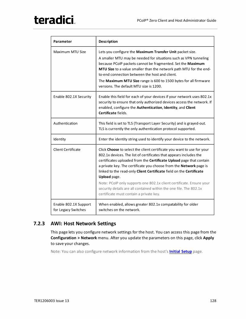
Parameter Description
Maximum MTU Size Lets you configure the Maximum Transfer Unit packet size.A smaller MTU may be needed for situations such as VPN tunnelingbecause PCoIP packets cannot be fragmented. Set the MaximumMTU Size to a value smaller than the network path MTU for the end-to-end connection between the host and client.The Maximum MTU Size range is 600 to 1500 bytes for all firmwareversions. The default MTU size is 1200.
Enable 802.1X Security Enable this field for each of your devices if your network uses 802.1xsecurity to ensure that only authorized devices access the network. Ifenabled, configure the Authentication, Identity, and ClientCertificate fields.
Authentication This field is set to TLS (Transport Layer Security) and is grayed-out.TLS is currently the only authentication protocol supported.
Identity Enter the identity string used to identify your device to the network.
Client Certificate Click Choose to select the client certificate you want to use for your802.1x devices. The list of certificates that appears includes thecertificates uploaded from the Certificate Upload page that containa private key. The certificate you choose from the Network page islinked to the read-only Client Certificate field on the CertificateUpload page.Note: PCoIP only supports one 802.1x client certificate. Ensure yoursecurity details are all contained within the one file. The 802.1xcertificate must contain a private key.
Enable 802.1X Supportfor Legacy Switches
When enabled, allows greater 802.1x compatability for olderswitches on the network.
7.2.3 AWI: Host Network SettingsThis page lets you configure network settings for the host. You can access this page from theConfiguration > Networkmenu. After you update the parameters on this page, click Applyto save your changes.
Note: You can also configure network information from the host's Initial Setup page.
TER1206003 Issue 13 128
PCoIP® Zero Client and Host Administrator Guide
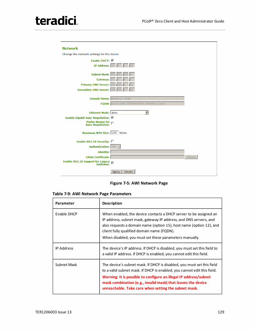
Figure 7-5: AWI Network Page
Table 7-9: AWI Network Page Parameters
Parameter Description
Enable DHCP When enabled, the device contacts a DHCP server to be assigned anIP address, subnet mask, gateway IP address, and DNS servers, andalso requests a domain name (option 15), host name (option 12), andclient fully qualified domain name (FQDN).When disabled, you must set these parameters manually.
IP Address The device's IP address. If DHCP is disabled, you must set this field toa valid IP address. If DHCP is enabled, you cannot edit this field.
Subnet Mask The device's subnet mask. If DHCP is disabled, you must set this fieldto a valid subnet mask. If DHCP is enabled, you cannot edit this field.Warning: It is possible to configure an illegal IP address/subnetmask combination (e.g., invalid mask) that leaves the deviceunreachable. Take care when setting the subnet mask.
TER1206003 Issue 13 129
PCoIP® Zero Client and Host Administrator Guide

Parameter Description
Gateway The device's gateway IP address. If DHCP is disabled, this field isrequired. If DHCP is enabled, you cannot edit this field.
Primary DNS Server The device's primary DNS IP address. This field is optional. If the DNSserver IP address is configured when using a connection manager,the connection manager address may be set as an FQDN instead ofan IP address.
Secondary DNS Server The device's secondary DNS IP address. This field is optional. If theDNS server IP address is configured when using a connectionmanager, the connection manager address may be set as an FQDNinstead of an IP address.
Domain Name The domain named of the device (e.g., "domain.local"). This field isoptional.
FQDN The fully qualified domain name for the device. The default is pcoip-host-<MAC> or pcoip-portal-<MAC> where <MAC> is the device'sMAC address. If used, the domain name is appended (for example,pcoip-host-<MAC>.domain.local). This field is read-only on this page.Note: To use the FQDN feature, the DNS server with DHCP option 81must be available and properly configured.
Ethernet Mode Lets you configure the Ethernet mode of the device as follows:l Autol 100 Mbps Full-Duplexl 10 Mbps Full-DuplexWhen you choose 10 Mbps Full Duplex or 100 Mbps Full-Duplex andthen click Apply, the following warning message appears:"Warning: When Auto-Negotiation is disabled on the PCoIP device, itmust also be disabled on the switch. Additionally, the PCoIP deviceand switch must be configured to use the same speed and duplexparameters. Different parameters may result in a loss of networkconnectivity. Are you sure you want to continue?"Click OK to change the parameter.Note: You should always set the Ethernet mode to Auto and only use10 Mbps Full-Duplex or 100 Mbps Full-Duplex when the othernetwork equipment (e.g., a switch) is also configured to operate at10 Mbps full-duplex or 100 Mbps full-duplex. An improperly setEthernet mode may result in the network operating at half-duplex,which is not supported by the PCoIP protocol. The session will beseverely degraded and eventually dropped.
TER1206003 Issue 13 130
PCoIP® Zero Client and Host Administrator Guide
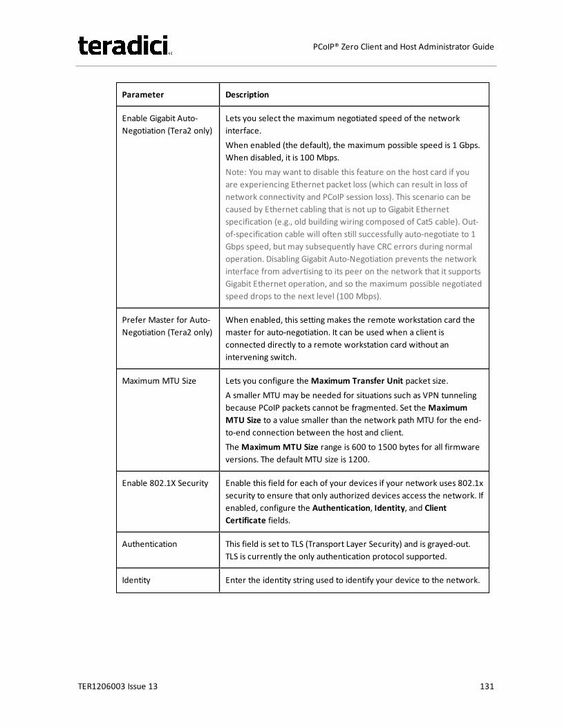
Parameter Description
Enable Gigabit Auto-Negotiation (Tera2 only)
Lets you select the maximum negotiated speed of the networkinterface.When enabled (the default), the maximum possible speed is 1 Gbps.When disabled, it is 100 Mbps.Note: You may want to disable this feature on the host card if youare experiencing Ethernet packet loss (which can result in loss ofnetwork connectivity and PCoIP session loss). This scenario can becaused by Ethernet cabling that is not up to Gigabit Ethernetspecification (e.g., old building wiring composed of Cat5 cable). Out-of-specification cable will often still successfully auto-negotiate to 1Gbps speed, but may subsequently have CRC errors during normaloperation. Disabling Gigabit Auto-Negotiation prevents the networkinterface from advertising to its peer on the network that it supportsGigabit Ethernet operation, and so the maximum possible negotiatedspeed drops to the next level (100 Mbps).
Prefer Master for Auto-Negotiation (Tera2 only)
When enabled, this setting makes the remote workstation card themaster for auto-negotiation. It can be used when a client isconnected directly to a remote workstation card without anintervening switch.
Maximum MTU Size Lets you configure the Maximum Transfer Unit packet size.A smaller MTU may be needed for situations such as VPN tunnelingbecause PCoIP packets cannot be fragmented. Set the MaximumMTU Size to a value smaller than the network path MTU for the end-to-end connection between the host and client.The Maximum MTU Size range is 600 to 1500 bytes for all firmwareversions. The default MTU size is 1200.
Enable 802.1X Security Enable this field for each of your devices if your network uses 802.1xsecurity to ensure that only authorized devices access the network. Ifenabled, configure the Authentication, Identity, and ClientCertificate fields.
Authentication This field is set to TLS (Transport Layer Security) and is grayed-out.TLS is currently the only authentication protocol supported.
Identity Enter the identity string used to identify your device to the network.
TER1206003 Issue 13 131
PCoIP® Zero Client and Host Administrator Guide
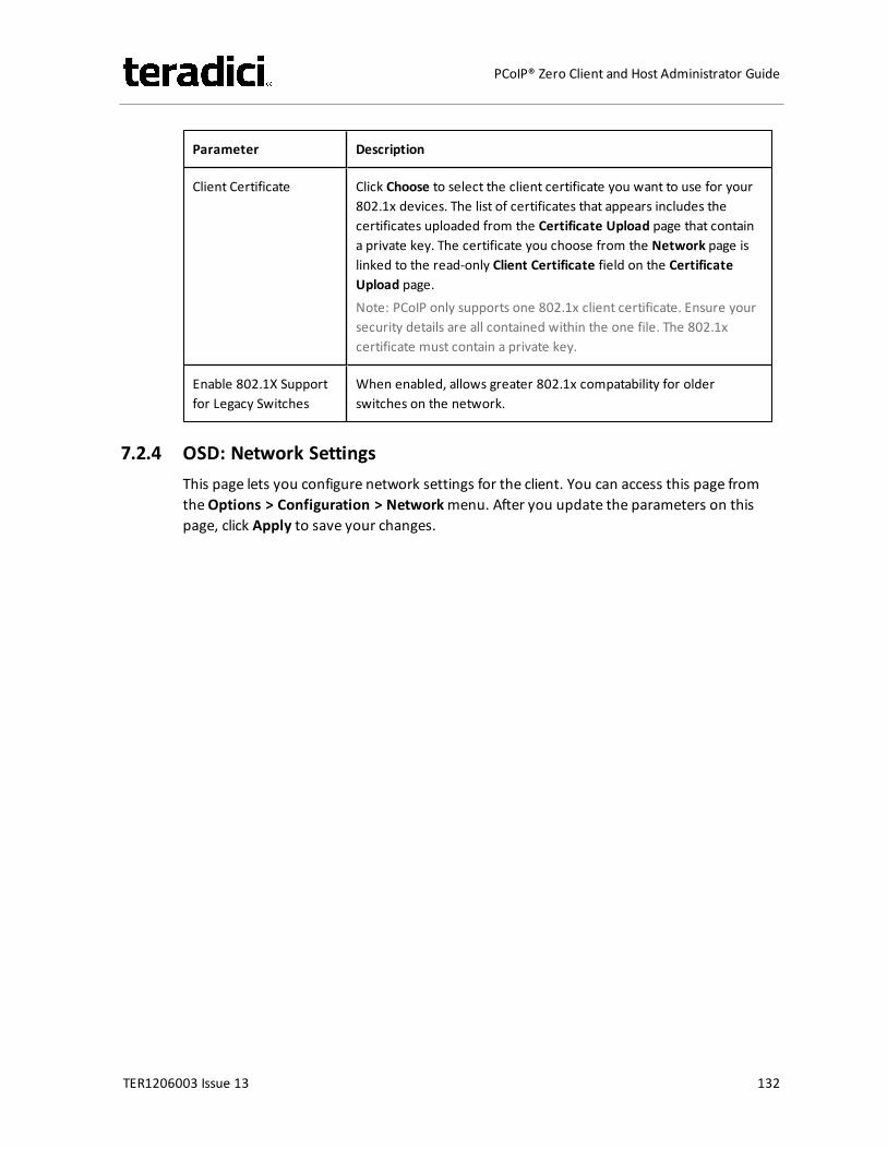
Parameter Description
Client Certificate Click Choose to select the client certificate you want to use for your802.1x devices. The list of certificates that appears includes thecertificates uploaded from the Certificate Upload page that containa private key. The certificate you choose from the Network page islinked to the read-only Client Certificate field on the CertificateUpload page.Note: PCoIP only supports one 802.1x client certificate. Ensure yoursecurity details are all contained within the one file. The 802.1xcertificate must contain a private key.
Enable 802.1X Supportfor Legacy Switches
When enabled, allows greater 802.1x compatability for olderswitches on the network.
7.2.4 OSD: Network SettingsThis page lets you configure network settings for the client. You can access this page fromtheOptions > Configuration > Networkmenu. After you update the parameters on thispage, click Apply to save your changes.
TER1206003 Issue 13 132
PCoIP® Zero Client and Host Administrator Guide
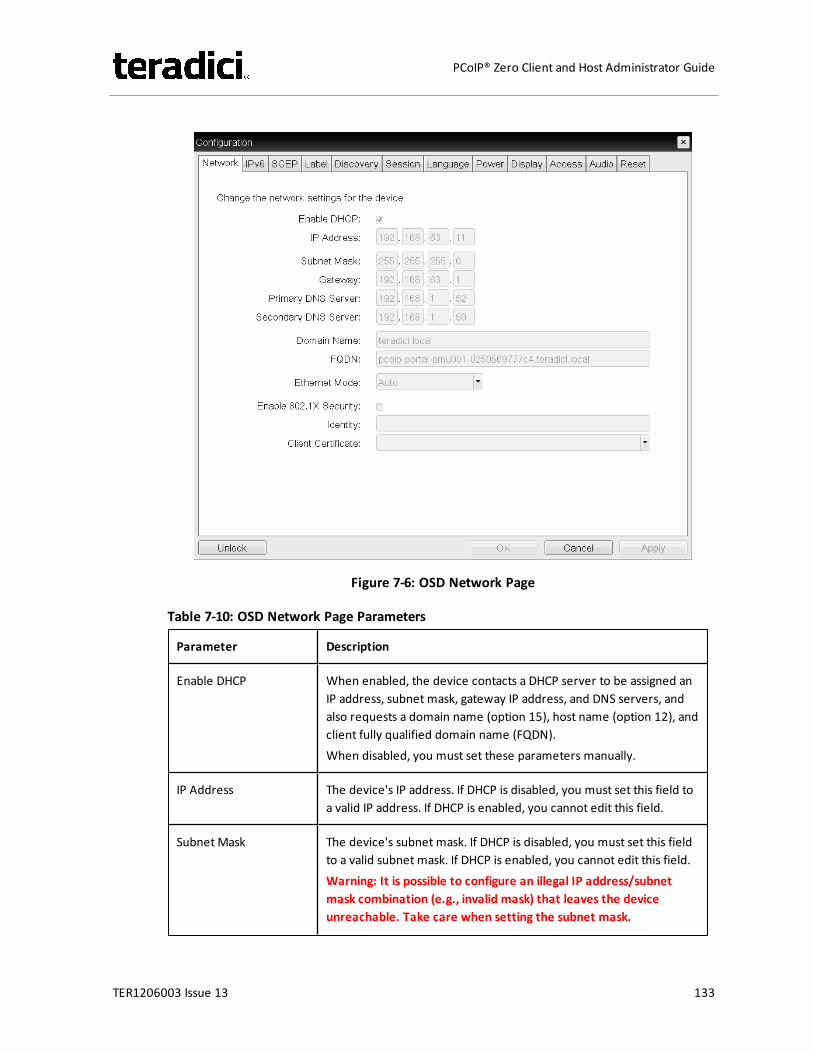
Figure 7-6: OSD Network Page
Table 7-10: OSD Network Page Parameters
Parameter Description
Enable DHCP When enabled, the device contacts a DHCP server to be assigned anIP address, subnet mask, gateway IP address, and DNS servers, andalso requests a domain name (option 15), host name (option 12), andclient fully qualified domain name (FQDN).When disabled, you must set these parameters manually.
IP Address The device's IP address. If DHCP is disabled, you must set this field toa valid IP address. If DHCP is enabled, you cannot edit this field.
Subnet Mask The device's subnet mask. If DHCP is disabled, you must set this fieldto a valid subnet mask. If DHCP is enabled, you cannot edit this field.Warning: It is possible to configure an illegal IP address/subnetmask combination (e.g., invalid mask) that leaves the deviceunreachable. Take care when setting the subnet mask.
TER1206003 Issue 13 133
PCoIP® Zero Client and Host Administrator Guide
Parameter Description
Gateway The device's gateway IP address. If DHCP is disabled, this field isrequired. If DHCP is enabled, you cannot edit this field.
Primary DNS Server The device's primary DNS IP address. This field is optional. If the DNSserver IP address is configured when using a connection manager,the connection manager address may be set as an FQDN instead ofan IP address.
Secondary DNS Server The device's secondary DNS IP address. This field is optional. If theDNS server IP address is configured when using a connectionmanager, the connection manager address may be set as an FQDNinstead of an IP address.
Domain Name The domain named of the device (e.g., "domain.local"). This field isoptional.
FQDN The fully qualified domain name for the device. The default is pcoip-host-<MAC> or pcoip-portal-<MAC> where <MAC> is the device'sMAC address. If used, the domain name is appended (for example,pcoip-host-<MAC>.domain.local). This field is read-only on this page.Note: To use the FQDN feature, the DNS server with DHCP option 81must be available and properly configured.
Ethernet Mode Lets you configure the Ethernet mode of the device as follows:l Autol 100 Mbps Full-Duplexl 10 Mbps Full-DuplexWhen you choose 10 Mbps Full Duplex or 100 Mbps Full-Duplex andthen click Apply, the following warning message appears:"Warning: When Auto-Negotiation is disabled on the PCoIP device, itmust also be disabled on the switch. Additionally, the PCoIP deviceand switch must be configured to use the same speed and duplexparameters. Different parameters may result in a loss of networkconnectivity. Are you sure you want to continue?"Click OK to change the parameter.Note: You should always set the Ethernet mode to Auto and only use10 Mbps Full-Duplex or 100 Mbps Full-Duplex when the othernetwork equipment (e.g., a switch) is also configured to operate at10 Mbps full-duplex or 100 Mbps full-duplex. An improperly setEthernet mode may result in the network operating at half-duplex,which is not supported by the PCoIP protocol. The session will beseverely degraded and eventually dropped.
TER1206003 Issue 13 134
PCoIP® Zero Client and Host Administrator Guide
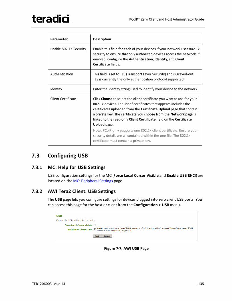
Parameter Description
Enable 802.1X Security Enable this field for each of your devices if your network uses 802.1xsecurity to ensure that only authorized devices access the network. Ifenabled, configure the Authentication, Identity, and ClientCertificate fields.
Authentication This field is set to TLS (Transport Layer Security) and is grayed-out.TLS is currently the only authentication protocol supported.
Identity Enter the identity string used to identify your device to the network.
Client Certificate Click Choose to select the client certificate you want to use for your802.1x devices. The list of certificates that appears includes thecertificates uploaded from the Certificate Upload page that containa private key. The certificate you choose from the Network page islinked to the read-only Client Certificate field on the CertificateUpload page.Note: PCoIP only supports one 802.1x client certificate. Ensure yoursecurity details are all contained within the one file. The 802.1xcertificate must contain a private key.
7.3 Configuring USB
7.3.1 MC: Help for USB SettingsUSB configuration settings for theMC (Force Local Cursor Visible and Enable USB EHCI) arelocated on theMC: Peripheral Settings page.
7.3.2 AWI Tera2 Client: USB SettingsTheUSB page lets you configure settings for devices plugged into zero client USB ports. Youcan access this page for the host or client from the Configuration > USBmenu.
Figure 7-7: AWI USB Page
TER1206003 Issue 13 135
PCoIP® Zero Client and Host Administrator Guide
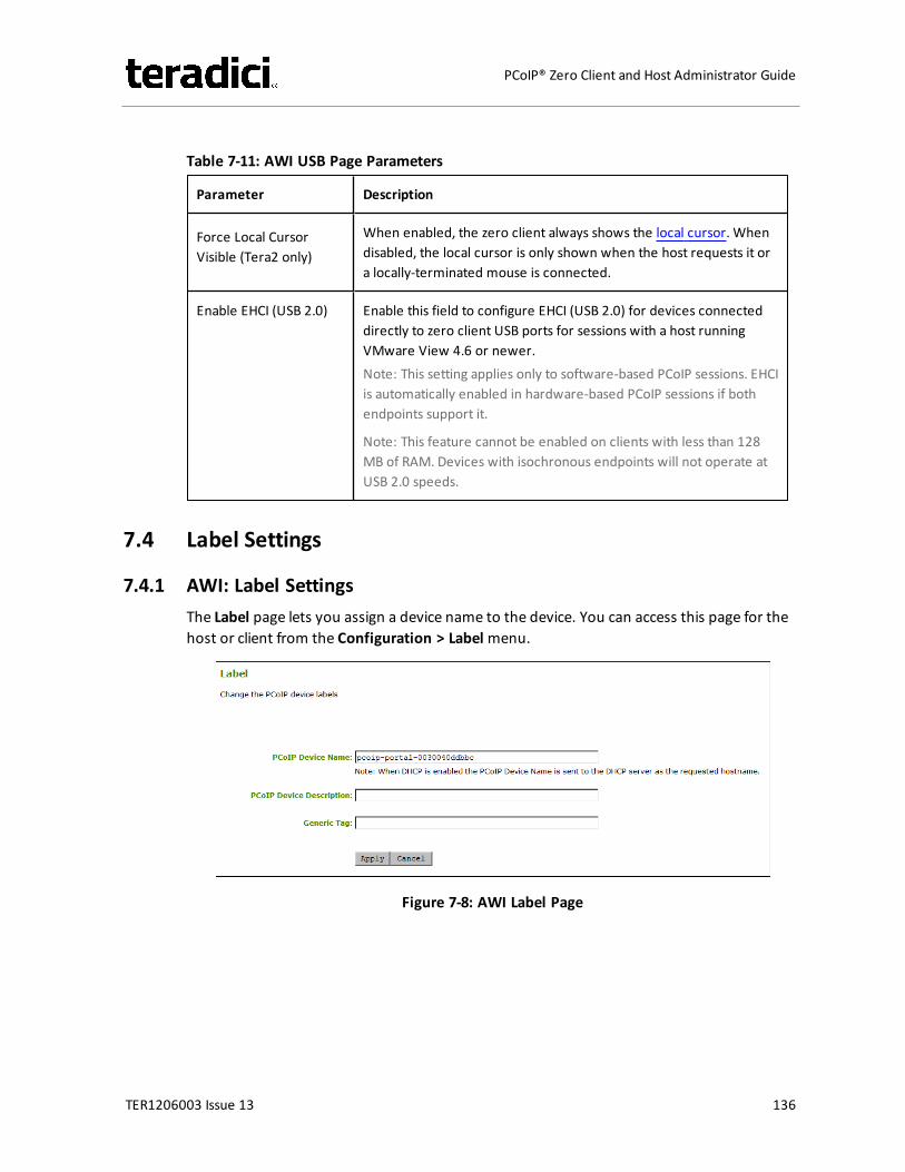
Table 7-11: AWI USB Page Parameters
Parameter Description
Force Local CursorVisible (Tera2 only)
When enabled, the zero client always shows the local cursor. Whendisabled, the local cursor is only shown when the host requests it ora locally-terminated mouse is connected.
Enable EHCI (USB 2.0) Enable this field to configure EHCI (USB 2.0) for devices connecteddirectly to zero client USB ports for sessions with a host runningVMware View 4.6 or newer.Note: This setting applies only to software-based PCoIP sessions. EHCIis automatically enabled in hardware-based PCoIP sessions if bothendpoints support it.
Note: This feature cannot be enabled on clients with less than 128MB of RAM. Devices with isochronous endpoints will not operate atUSB 2.0 speeds.
7.4 Label Settings
7.4.1 AWI: Label SettingsThe Label page lets you assign a device name to the device. You can access this page for thehost or client from the Configuration > Labelmenu.
Figure 7-8: AWI Label Page
TER1206003 Issue 13 136
PCoIP® Zero Client and Host Administrator Guide
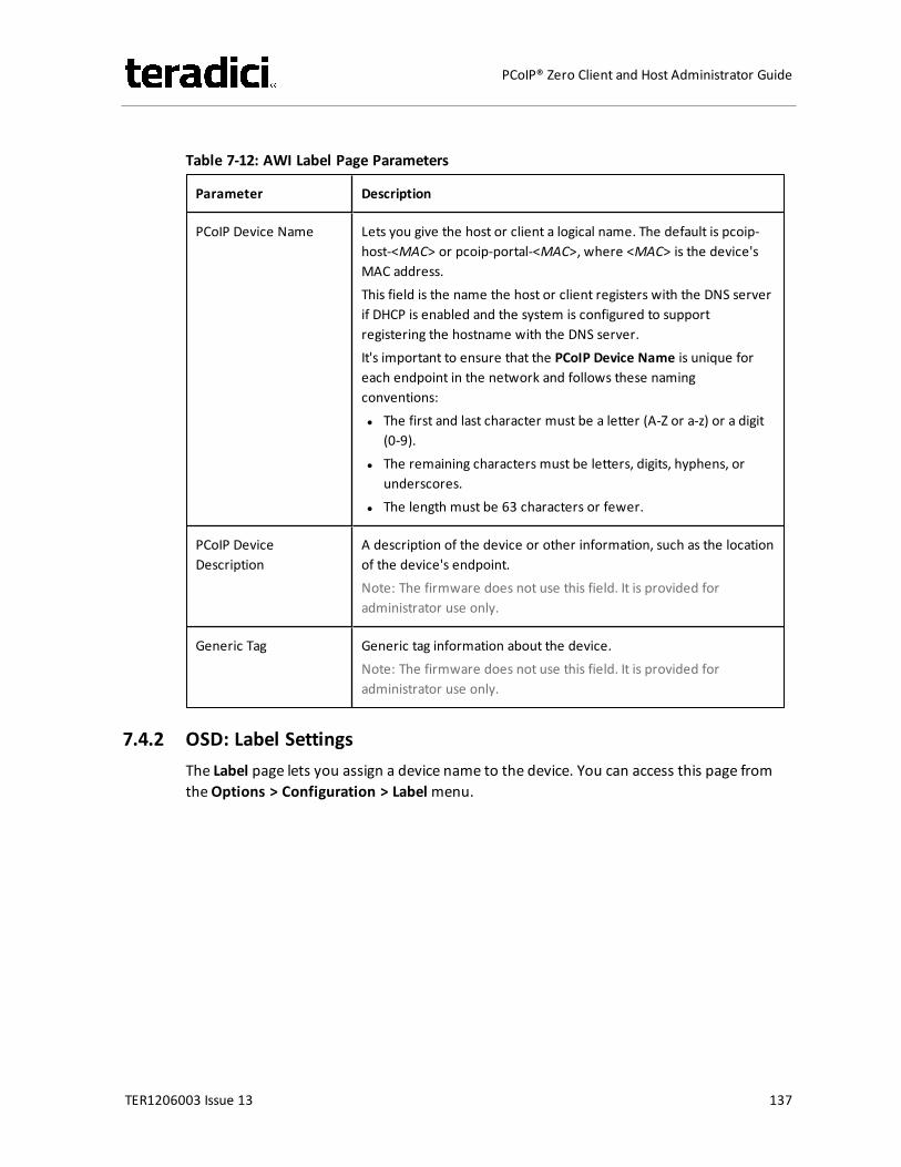
Table 7-12: AWI Label Page Parameters
Parameter Description
PCoIP Device Name Lets you give the host or client a logical name. The default is pcoip-host-<MAC> or pcoip-portal-<MAC>, where <MAC> is the device'sMAC address.This field is the name the host or client registers with the DNS serverif DHCP is enabled and the system is configured to supportregistering the hostname with the DNS server.It's important to ensure that the PCoIP Device Name is unique foreach endpoint in the network and follows these namingconventions:l The first and last character must be a letter (A-Z or a-z) or a digit
(0-9).l The remaining characters must be letters, digits, hyphens, or
underscores.l The length must be 63 characters or fewer.
PCoIP DeviceDescription
A description of the device or other information, such as the locationof the device's endpoint.Note: The firmware does not use this field. It is provided foradministrator use only.
Generic Tag Generic tag information about the device.Note: The firmware does not use this field. It is provided foradministrator use only.
7.4.2 OSD: Label SettingsThe Label page lets you assign a device name to the device. You can access this page fromtheOptions > Configuration > Labelmenu.
TER1206003 Issue 13 137
PCoIP® Zero Client and Host Administrator Guide
Figure 7-9: OSD Label Page
Table 7-13: OSD Label Page Parameters
Parameter Description
PCoIP Device Name Lets you give the host or client a logical name. The default is pcoip-host-<MAC> or pcoip-portal-<MAC>, where <MAC> is the device'sMAC address.This field is the name the host or client registers with the DNS serverif DHCP is enabled and the system is configured to supportregistering the hostname with the DNS server.It's important to ensure that the PCoIP Device Name is unique foreach endpoint in the network and follows these namingconventions:l The first and last character must be a letter (A-Z or a-z) or a digit
(0-9).l The remaining characters must be letters, digits, hyphens, or
underscores.l The length must be 63 characters or fewer.
TER1206003 Issue 13 138
PCoIP® Zero Client and Host Administrator Guide
Parameter Description
PCoIP DeviceDescription
A description of the device or other information, such as the locationof the device's endpoint.Note: The firmware does not use this field. It is provided foradministrator use only.
Generic Tag Generic tag information about the device.Note: The firmware does not use this field. It is provided foradministrator use only.
7.5 Access Settings
7.5.1 MC: Help for Access SettingsAdministrative access settings for theManagement Console are located on the followingpages:
l Hiding the OSD Configurationmenu: seeHide Options -> Configuration on the OSDSettings page
l Disabling the AWI: see Enable Web Interface on the Security Settings page.l Disabling themanagement console interface: seeDisable Management Console
Interface on the Security Settings page.
Note: At least one of the device's threemanagement configuration interfaces (OSD, AWI, orMC)must remain enabled at all times.
7.5.2 AWI: Access SettingsThe Access page lets you prevent the device from being managed by theMC (or any otherPCoIP devicemanagement tool), and lets you disable administrative access to the device'sAWI. It also provides an option to force an administrative password change the next time theAWI or OSD is accessed.
You can access this page from the Configuration > Accessmenu.
Note: At least one of the device's threemanagement configuration interfaces (OSD, AWI, orMC)must remain enabled at all times. If the device has its OSD Configurationmenu hidden(seeMC OSD Settings), you will receive an error message if you try to disable both theMCinterface and the AWI from this page. In this situation, only one of these interfaces can bedisabled.
TER1206003 Issue 13 139
PCoIP® Zero Client and Host Administrator Guide
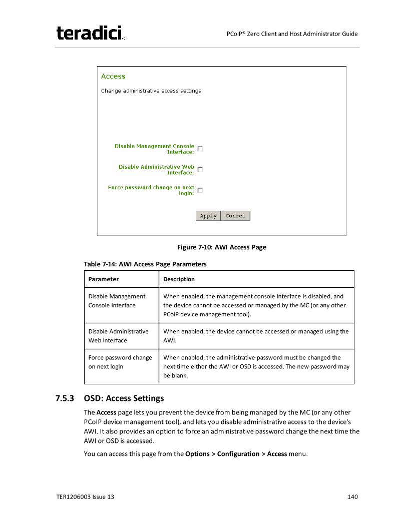
Figure 7-10: AWI Access Page
Table 7-14: AWI Access Page Parameters
Parameter Description
Disable ManagementConsole Interface
When enabled, the management console interface is disabled, andthe device cannot be accessed or managed by the MC (or any otherPCoIP device management tool).
Disable AdministrativeWeb Interface
When enabled, the device cannot be accessed or managed using theAWI.
Force password changeon next login
When enabled, the administrative password must be changed thenext time either the AWI or OSD is accessed. The new password maybe blank.
7.5.3 OSD: Access SettingsThe Access page lets you prevent the device from being managed by theMC (or any otherPCoIP devicemanagement tool), and lets you disable administrative access to the device'sAWI. It also provides an option to force an administrative password change the next time theAWI or OSD is accessed.
You can access this page from theOptions > Configuration > Accessmenu.
TER1206003 Issue 13 140
PCoIP® Zero Client and Host Administrator Guide
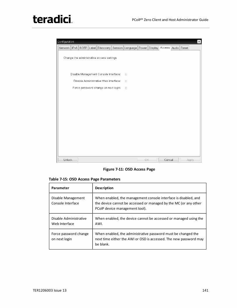
Figure 7-11: OSD Access Page
Table 7-15: OSD Access Page Parameters
Parameter Description
Disable ManagementConsole Interface
When enabled, the management console interface is disabled, andthe device cannot be accessed or managed by the MC (or any otherPCoIP device management tool).
Disable AdministrativeWeb Interface
When enabled, the device cannot be accessed or managed using theAWI.
Force password changeon next login
When enabled, the administrative password must be changed thenext time either the AWI or OSD is accessed. The new password maybe blank.
TER1206003 Issue 13 141
PCoIP® Zero Client and Host Administrator Guide
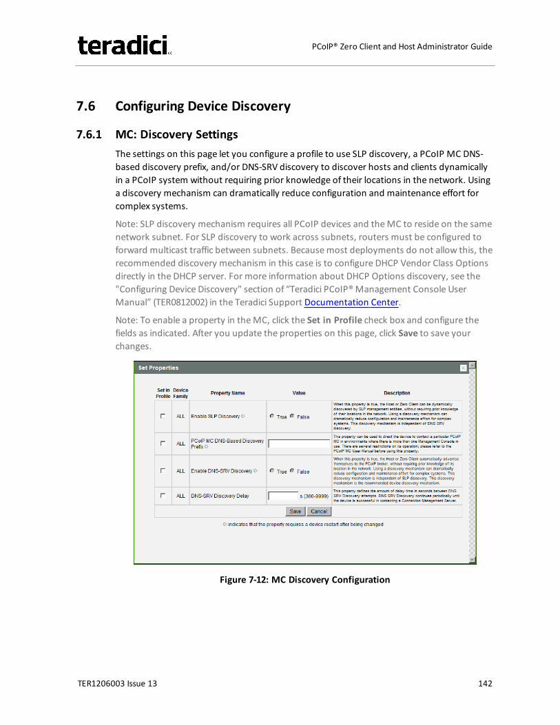
7.6 Configuring Device Discovery
7.6.1 MC: Discovery SettingsThe settings on this page let you configure a profile to use SLP discovery, a PCoIP MC DNS-based discovery prefix, and/or DNS-SRV discovery to discover hosts and clients dynamicallyin a PCoIP system without requiring prior knowledge of their locations in the network. Usinga discovery mechanism can dramatically reduce configuration and maintenance effort forcomplex systems.
Note: SLP discovery mechanism requires all PCoIP devices and theMC to reside on the samenetwork subnet. For SLP discovery to work across subnets, routers must be configured toforward multicast traffic between subnets. Becausemost deployments do not allow this, therecommended discovery mechanism in this case is to configure DHCP Vendor Class Optionsdirectly in the DHCP server. For more information about DHCP Options discovery, see the"Configuring Device Discovery" section of “Teradici PCoIP®Management Console UserManual” (TER0812002) in the Teradici Support Documentation Center.
Note: To enable a property in theMC, click the Set in Profile check box and configure thefields as indicated. After you update the properties on this page, click Save to save yourchanges.
Figure 7-12: MC Discovery Configuration
TER1206003 Issue 13 142
PCoIP® Zero Client and Host Administrator Guide
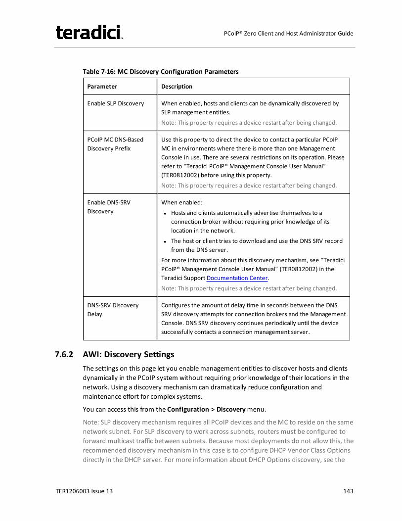
Table 7-16: MC Discovery Configuration Parameters
Parameter Description
Enable SLP Discovery When enabled, hosts and clients can be dynamically discovered bySLP management entities.Note: This property requires a device restart after being changed.
PCoIP MC DNS-BasedDiscovery Prefix
Use this property to direct the device to contact a particular PCoIPMC in environments where there is more than one ManagementConsole in use. There are several restrictions on its operation. Pleaserefer to “Teradici PCoIP® Management Console User Manual”(TER0812002) before using this property.Note: This property requires a device restart after being changed.
Enable DNS-SRVDiscovery
When enabled:l Hosts and clients automatically advertise themselves to a
connection broker without requiring prior knowledge of itslocation in the network.
l The host or client tries to download and use the DNS SRV recordfrom the DNS server.
For more information about this discovery mechanism, see “TeradiciPCoIP® Management Console User Manual” (TER0812002) in theTeradici Support Documentation Center.Note: This property requires a device restart after being changed.
DNS-SRV DiscoveryDelay
Configures the amount of delay time in seconds between the DNSSRV discovery attempts for connection brokers and the ManagementConsole. DNS SRV discovery continues periodically until the devicesuccessfully contacts a connection management server.
7.6.2 AWI: Discovery SettingsThe settings on this page let you enablemanagement entities to discover hosts and clientsdynamically in the PCoIP system without requiring prior knowledge of their locations in thenetwork. Using a discovery mechanism can dramatically reduce configuration andmaintenance effort for complex systems.
You can access this from the Configuration > Discoverymenu.
Note: SLP discovery mechanism requires all PCoIP devices and theMC to reside on the samenetwork subnet. For SLP discovery to work across subnets, routers must be configured toforward multicast traffic between subnets. Becausemost deployments do not allow this, therecommended discovery mechanism in this case is to configure DHCP Vendor Class Optionsdirectly in the DHCP server. For more information about DHCP Options discovery, see the
TER1206003 Issue 13 143
PCoIP® Zero Client and Host Administrator Guide
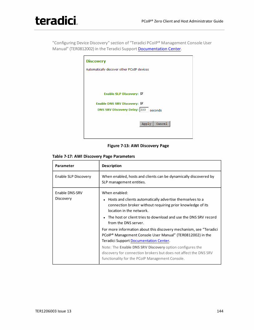
"Configuring Device Discovery" section of “Teradici PCoIP®Management Console UserManual” (TER0812002) in the Teradici Support Documentation Center.
Figure 7-13: AWI Discovery Page
Table 7-17: AWI Discovery Page Parameters
Parameter Description
Enable SLP Discovery When enabled, hosts and clients can be dynamically discovered bySLP management entities.
Enable DNS-SRVDiscovery
When enabled:l Hosts and clients automatically advertise themselves to a
connection broker without requiring prior knowledge of itslocation in the network.
l The host or client tries to download and use the DNS SRV recordfrom the DNS server.
For more information about this discovery mechanism, see “TeradiciPCoIP® Management Console User Manual” (TER0812002) in theTeradici Support Documentation Center.Note: The Enable DNS SRV Discovery option configures thediscovery for connection brokers but does not affect the DNS SRVfunctionality for the PCoIP Management Console.
TER1206003 Issue 13 144
PCoIP® Zero Client and Host Administrator Guide
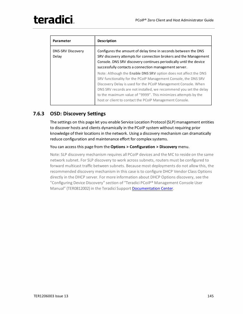
Parameter Description
DNS-SRV DiscoveryDelay
Configures the amount of delay time in seconds between the DNSSRV discovery attempts for connection brokers and the ManagementConsole. DNS SRV discovery continues periodically until the devicesuccessfully contacts a connection management server.Note: Although the Enable DNS SRV option does not affect the DNSSRV functionality for the PCoIP Management Console, the DNS SRVDiscovery Delay is used for the PCoIP Management Console. WhenDNS SRV records are not installed, we recommend you set the delayto the maximum value of “9999”. This minimizes attempts by thehost or client to contact the PCoIP Management Console.
7.6.3 OSD: Discovery SettingsThe settings on this page let you enable Service Location Protocol (SLP)management entitiesto discover hosts and clients dynamically in the PCoIP system without requiring priorknowledge of their locations in the network. Using a discovery mechanism can dramaticallyreduce configuration and maintenance effort for complex systems.
You can access this page from theOptions > Configuration > Discoverymenu.
Note: SLP discovery mechanism requires all PCoIP devices and theMC to reside on the samenetwork subnet. For SLP discovery to work across subnets, routers must be configured toforward multicast traffic between subnets. Becausemost deployments do not allow this, therecommended discovery mechanism in this case is to configure DHCP Vendor Class Optionsdirectly in the DHCP server. For more information about DHCP Options discovery, see the"Configuring Device Discovery" section of “Teradici PCoIP®Management Console UserManual” (TER0812002) in the Teradici Support Documentation Center.
TER1206003 Issue 13 145
PCoIP® Zero Client and Host Administrator Guide
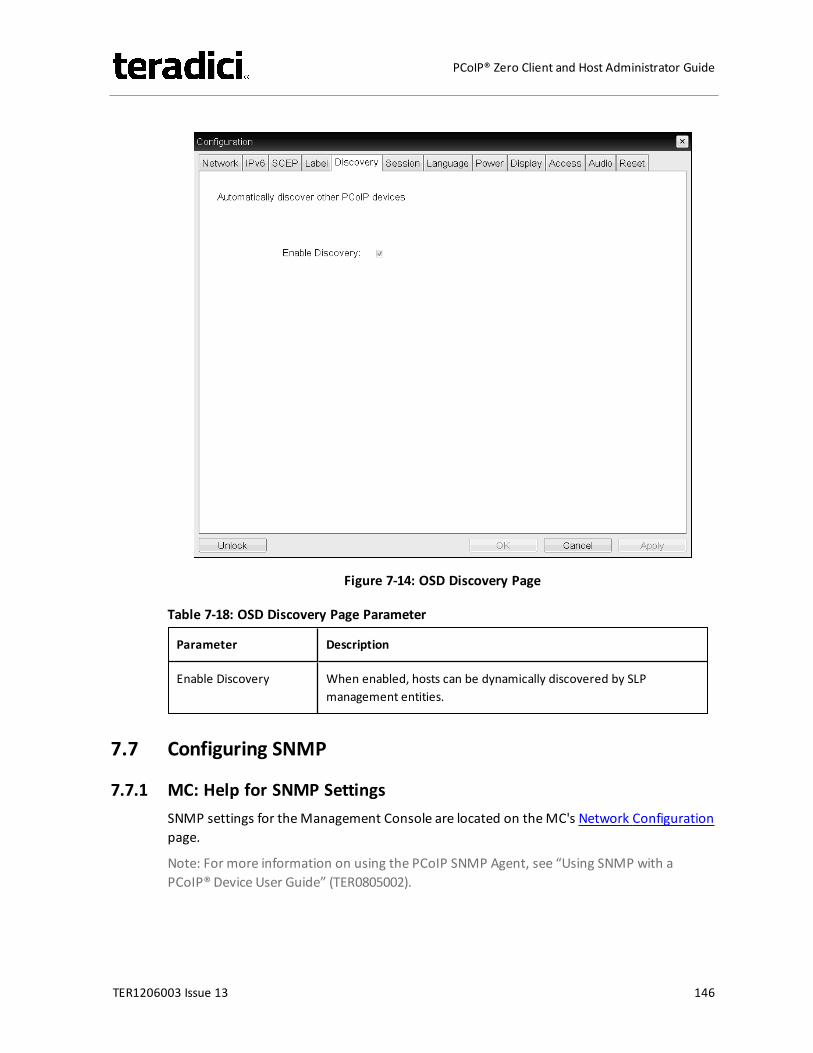
Figure 7-14: OSD Discovery Page
Table 7-18: OSD Discovery Page Parameter
Parameter Description
Enable Discovery When enabled, hosts can be dynamically discovered by SLPmanagement entities.
7.7 Configuring SNMP
7.7.1 MC: Help for SNMP SettingsSNMP settings for theManagement Console are located on theMC's Network Configurationpage.
Note: For more information on using the PCoIP SNMP Agent, see “Using SNMP with aPCoIP® Device User Guide” (TER0805002).
TER1206003 Issue 13 146
PCoIP® Zero Client and Host Administrator Guide
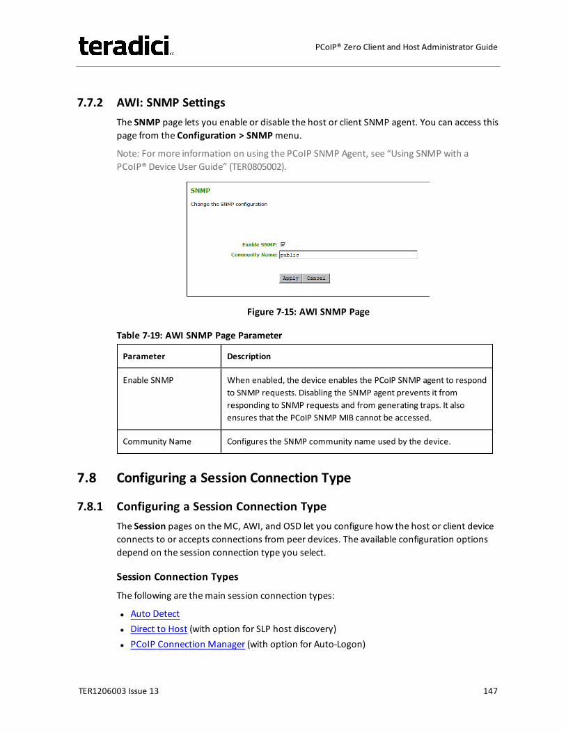
7.7.2 AWI: SNMP SettingsThe SNMP page lets you enable or disable the host or client SNMP agent. You can access thispage from the Configuration > SNMPmenu.
Note: For more information on using the PCoIP SNMP Agent, see “Using SNMP with aPCoIP® Device User Guide” (TER0805002).
Figure 7-15: AWI SNMP Page
Table 7-19: AWI SNMP Page Parameter
Parameter Description
Enable SNMP When enabled, the device enables the PCoIP SNMP agent to respondto SNMP requests. Disabling the SNMP agent prevents it fromresponding to SNMP requests and from generating traps. It alsoensures that the PCoIP SNMP MIB cannot be accessed.
Community Name Configures the SNMP community name used by the device.
7.8 Configuring a Session Connection Type
7.8.1 Configuring a Session Connection TypeThe Session pages on theMC, AWI, and OSD let you configure how the host or client deviceconnects to or accepts connections from peer devices. The available configuration optionsdepend on the session connection type you select.
Session Connection Types
The following are themain session connection types:
l Auto Detectl Direct to Host (with option for SLP host discovery)l PCoIP Connection Manager (with option for Auto-Logon)
TER1206003 Issue 13 147
PCoIP® Zero Client and Host Administrator Guide
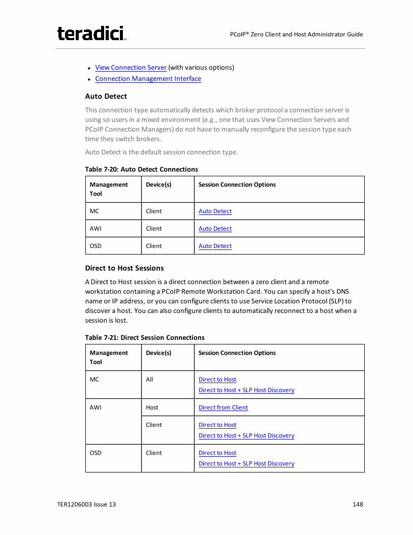
l View Connection Server (with various options)l Connection Management Interface
Auto Detect
This connection type automatically detects which broker protocol a connection server isusing so users in a mixed environment (e.g., one that uses View Connection Servers andPCoIP Connection Managers) do not have to manually reconfigure the session type eachtime they switch brokers.
Auto Detect is the default session connection type.
Table 7-20: Auto Detect Connections
ManagementTool
Device(s) Session Connection Options
MC Client Auto Detect
AWI Client Auto Detect
OSD Client Auto Detect
Direct to Host Sessions
ADirect to Host session is a direct connection between a zero client and a remoteworkstation containing a PCoIP RemoteWorkstation Card. You can specify a host's DNSname or IP address, or you can configure clients to use Service Location Protocol (SLP) todiscover a host. You can also configure clients to automatically reconnect to a host when asession is lost.
Table 7-21: Direct Session Connections
ManagementTool
Device(s) Session Connection Options
MC All Direct to HostDirect to Host + SLP Host Discovery
AWI Host Direct from Client
Client Direct to HostDirect to Host + SLP Host Discovery
OSD Client Direct to HostDirect to Host + SLP Host Discovery
TER1206003 Issue 13 148
PCoIP® Zero Client and Host Administrator Guide
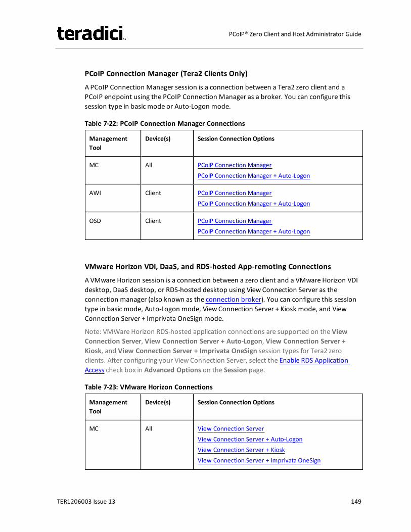
PCoIP Connection Manager (Tera2 Clients Only)
A PCoIP Connection Manager session is a connection between a Tera2 zero client and aPCoIP endpoint using the PCoIP Connection Manager as a broker. You can configure thissession type in basic mode or Auto-Logon mode.
Table 7-22: PCoIP Connection Manager Connections
ManagementTool
Device(s) Session Connection Options
MC All PCoIP Connection ManagerPCoIP Connection Manager + Auto-Logon
AWI Client PCoIP Connection ManagerPCoIP Connection Manager + Auto-Logon
OSD Client PCoIP Connection ManagerPCoIP Connection Manager + Auto-Logon
VMware Horizon VDI, DaaS, and RDS-hosted App-remoting Connections
A VMware Horizon session is a connection between a zero client and a VMware Horizon VDIdesktop, DaaS desktop, or RDS-hosted desktop using View Connection Server as theconnection manager (also known as the connection broker). You can configure this sessiontype in basic mode, Auto-Logon mode, View Connection Server + Kiosk mode, and ViewConnection Server + Imprivata OneSign mode.
Note: VMWare Horizon RDS-hosted application connections are supported on the ViewConnection Server, View Connection Server + Auto-Logon, View Connection Server +Kiosk, and View Connection Server + Imprivata OneSign session types for Tera2 zeroclients. After configuring your View Connection Server, select the Enable RDS ApplicationAccess check box in Advanced Options on the Session page.
Table 7-23: VMware Horizon Connections
ManagementTool
Device(s) Session Connection Options
MC All View Connection ServerView Connection Server + Auto-LogonView Connection Server + KioskView Connection Server + Imprivata OneSign
TER1206003 Issue 13 149
PCoIP® Zero Client and Host Administrator Guide
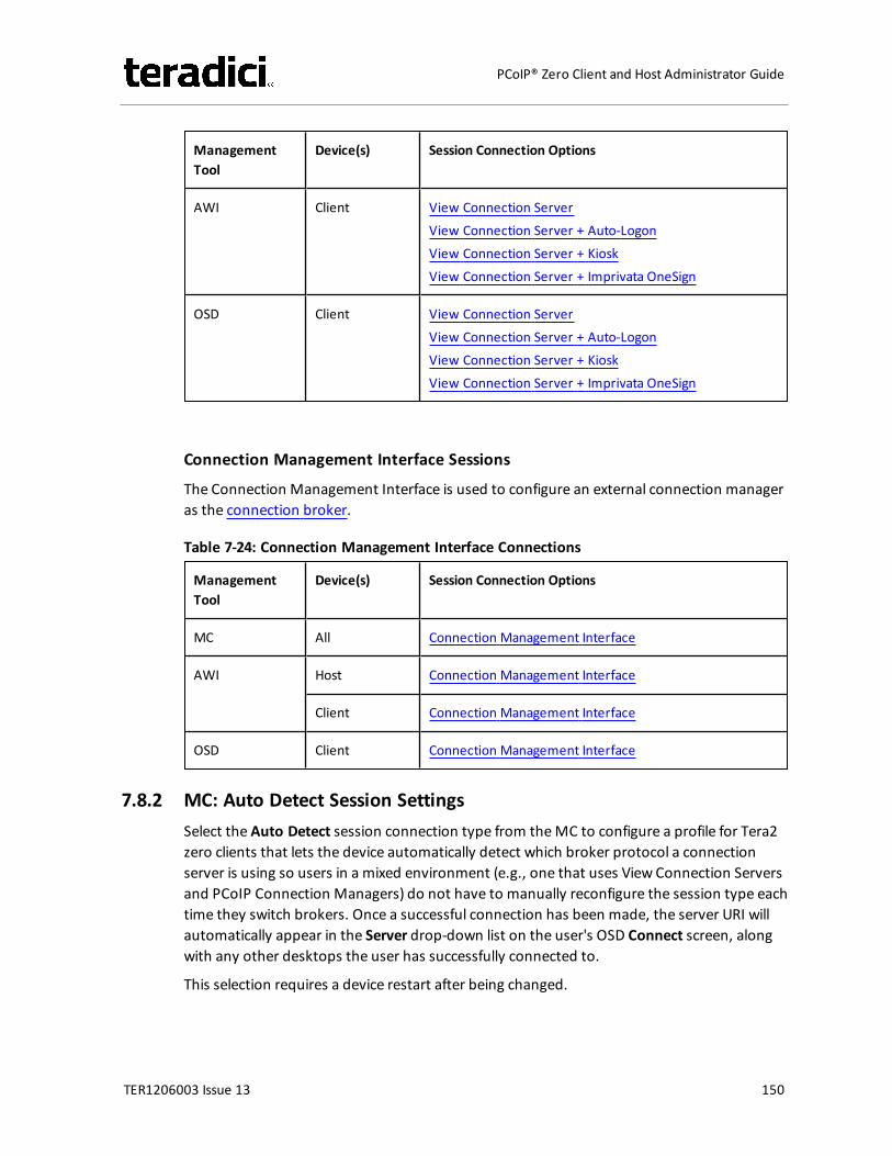
ManagementTool
Device(s) Session Connection Options
AWI Client View Connection ServerView Connection Server + Auto-LogonView Connection Server + KioskView Connection Server + Imprivata OneSign
OSD Client View Connection ServerView Connection Server + Auto-LogonView Connection Server + KioskView Connection Server + Imprivata OneSign
Connection Management Interface Sessions
The Connection Management Interface is used to configure an external connection manageras the connection broker.
Table 7-24: Connection Management Interface Connections
ManagementTool
Device(s) Session Connection Options
MC All Connection Management Interface
AWI Host Connection Management Interface
Client Connection Management Interface
OSD Client Connection Management Interface
7.8.2 MC: Auto Detect Session SettingsSelect the Auto Detect session connection type from theMC to configure a profile for Tera2zero clients that lets the device automatically detect which broker protocol a connectionserver is using so users in a mixed environment (e.g., one that uses View Connection Serversand PCoIP Connection Managers) do not have to manually reconfigure the session type eachtime they switch brokers. Once a successful connection has been made, the server URI willautomatically appear in the Server drop-down list on the user's OSD Connect screen, alongwith any other desktops the user has successfully connected to.
This selection requires a device restart after being changed.
TER1206003 Issue 13 150
PCoIP® Zero Client and Host Administrator Guide
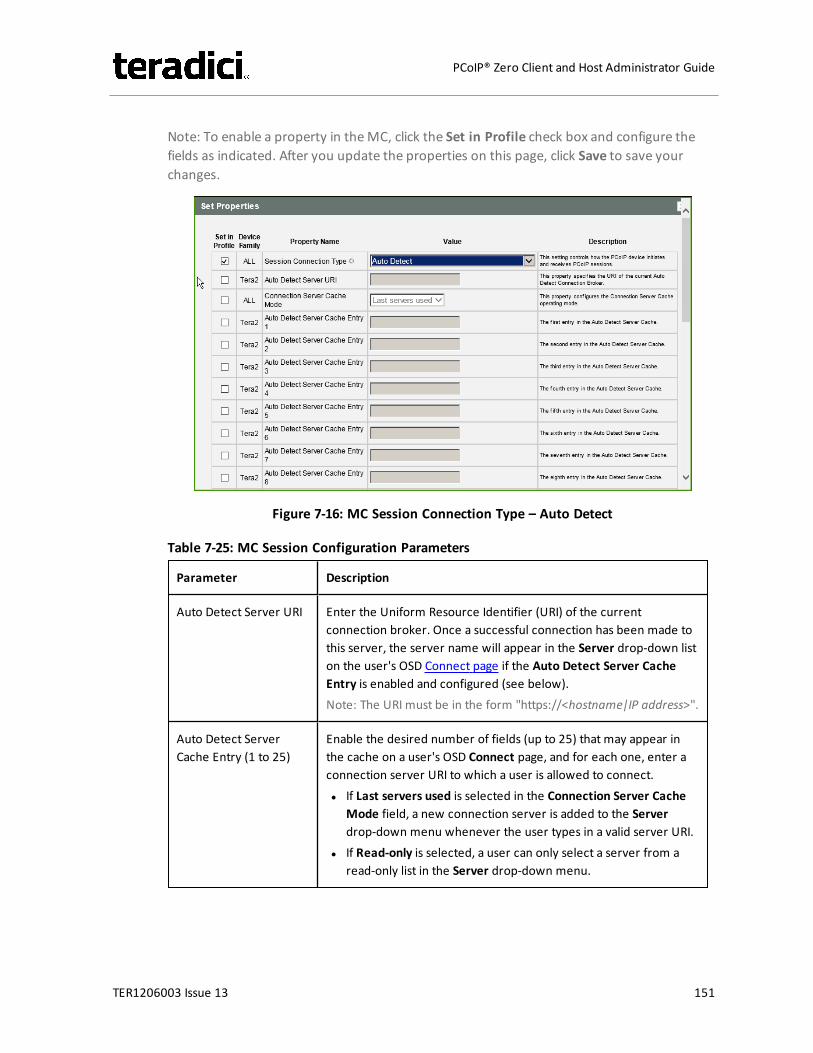
Note: To enable a property in theMC, click the Set in Profile check box and configure thefields as indicated. After you update the properties on this page, click Save to save yourchanges.
Figure 7-16: MC Session Connection Type – Auto Detect
Table 7-25: MC Session Configuration Parameters
Parameter Description
Auto Detect Server URI Enter the Uniform Resource Identifier (URI) of the currentconnection broker. Once a successful connection has been made tothis server, the server name will appear in the Server drop-down liston the user's OSD Connect page if the Auto Detect Server CacheEntry is enabled and configured (see below).Note: The URI must be in the form "https://<hostname|IP address>".
Auto Detect ServerCache Entry (1 to 25)
Enable the desired number of fields (up to 25) that may appear inthe cache on a user's OSD Connect page, and for each one, enter aconnection server URI to which a user is allowed to connect.l If Last servers used is selected in the Connection Server Cache
Mode field, a new connection server is added to the Serverdrop-down menu whenever the user types in a valid server URI.
l If Read-only is selected, a user can only select a server from aread-only list in the Server drop-down menu.
TER1206003 Issue 13 151
PCoIP® Zero Client and Host Administrator Guide
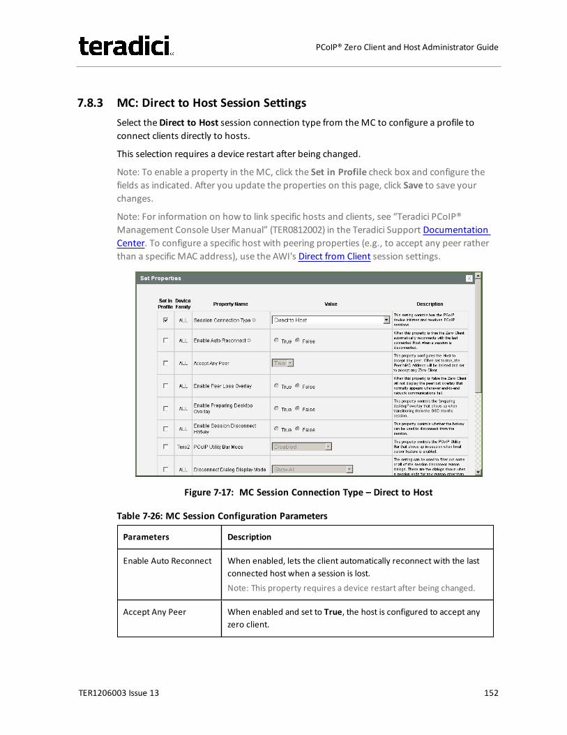
7.8.3 MC: Direct to Host Session SettingsSelect theDirect to Host session connection type from theMC to configure a profile toconnect clients directly to hosts.
This selection requires a device restart after being changed.
Note: To enable a property in theMC, click the Set in Profile check box and configure thefields as indicated. After you update the properties on this page, click Save to save yourchanges.
Note: For information on how to link specific hosts and clients, see “Teradici PCoIP®Management Console User Manual” (TER0812002) in the Teradici Support DocumentationCenter. To configure a specific host with peering properties (e.g., to accept any peer ratherthan a specific MAC address), use the AWI's Direct from Client session settings.
Figure 7-17: MC Session Connection Type – Direct to Host
Table 7-26: MC Session Configuration Parameters
Parameters Description
Enable Auto Reconnect When enabled, lets the client automatically reconnect with the lastconnected host when a session is lost.Note: This property requires a device restart after being changed.
Accept Any Peer When enabled and set to True, the host is configured to accept anyzero client.
TER1206003 Issue 13 152
PCoIP® Zero Client and Host Administrator Guide
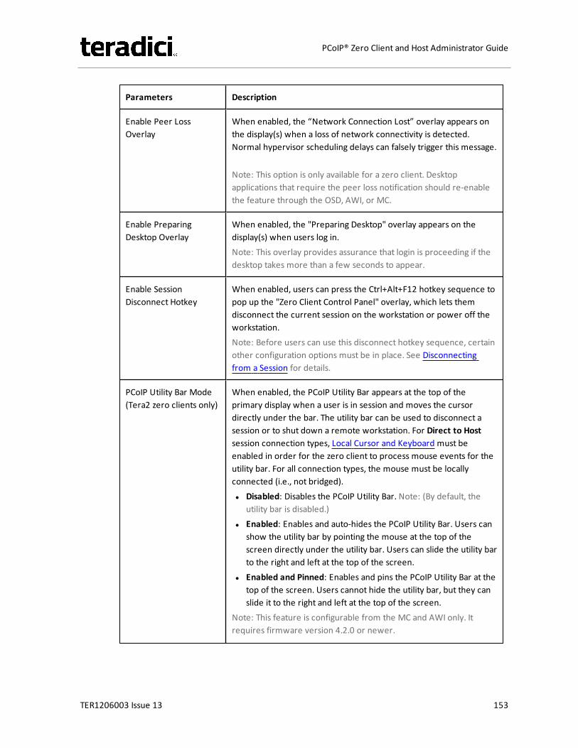
Parameters Description
Enable Peer LossOverlay
When enabled, the “Network Connection Lost” overlay appears onthe display(s) when a loss of network connectivity is detected.Normal hypervisor scheduling delays can falsely trigger this message.
Note: This option is only available for a zero client. Desktopapplications that require the peer loss notification should re-enablethe feature through the OSD, AWI, or MC.
Enable PreparingDesktop Overlay
When enabled, the "Preparing Desktop" overlay appears on thedisplay(s) when users log in.Note: This overlay provides assurance that login is proceeding if thedesktop takes more than a few seconds to appear.
Enable SessionDisconnect Hotkey
When enabled, users can press the Ctrl+Alt+F12 hotkey sequence topop up the "Zero Client Control Panel" overlay, which lets themdisconnect the current session on the workstation or power off theworkstation.Note: Before users can use this disconnect hotkey sequence, certainother configuration options must be in place. See Disconnectingfrom a Session for details.
PCoIP Utility Bar Mode(Tera2 zero clients only)
When enabled, the PCoIP Utility Bar appears at the top of theprimary display when a user is in session and moves the cursordirectly under the bar. The utility bar can be used to disconnect asession or to shut down a remote workstation. For Direct to Hostsession connection types, Local Cursor and Keyboard must beenabled in order for the zero client to process mouse events for theutility bar. For all connection types, the mouse must be locallyconnected (i.e., not bridged).l Disabled: Disables the PCoIP Utility Bar. Note: (By default, the
utility bar is disabled.)l Enabled: Enables and auto-hides the PCoIP Utility Bar. Users can
show the utility bar by pointing the mouse at the top of thescreen directly under the utility bar. Users can slide the utility barto the right and left at the top of the screen.
l Enabled and Pinned: Enables and pins the PCoIP Utility Bar at thetop of the screen. Users cannot hide the utility bar, but they canslide it to the right and left at the top of the screen.
Note: This feature is configurable from the MC and AWI only. Itrequires firmware version 4.2.0 or newer.
TER1206003 Issue 13 153
PCoIP® Zero Client and Host Administrator Guide

Parameters Description
Disconnect DialogDisplay Mode
This field lets you control what type of messages appear when asession is disconnected. There are three categories:Information: User- or administrator-initiated actions affecting thesession:l You have been disconnected because you logged in from
another location or your host was shut down or restarted.l You have been disconnected because an administrator
disconnected you.l You have been disconnected because you logged in from
another location.l You have been disconnected because you disconnected from
your workstation.Warning: System-initiated, but expected actions affecting thesession:l You have been disconnected because your session timed out.Error: Unexpected system-initiated actions causing session to fail:l You have been disconnected.l Unable to connect (0x1001). Please contact your IT
administrator.l Unable to connect (0x1002). Please contact your IT
administrator.l Session closed remotely.l Session closed remotely (unknown cause).l You have been disconnected due to a configuration error
(0x100). Please contact your IT administrator for assistance.l You have been disconnected due to a configuration error
(0x201). Please contact your IT administrator for assistance.l You have been disconnected due to a configuration error
(0x300). Please contact your IT administrator for assistance.l You have been disconnected due to a configuration error
(0x301). Please contact your IT administrator for assistance.l You have been disconnected due to a configuration error
(0x302). Please contact your IT administrator for assistance.l You have been disconnected due to a configuration error
(0x303). Please contact your IT administrator for assistance.l You have been disconnected due to a configuration error
(0x305). Please contact your IT administrator for assistance.l You have been disconnected due to a configuration error
(0x400). Please contact your IT administrator for assistance.l You have been disconnected due to a configuration error
TER1206003 Issue 13 154
PCoIP® Zero Client and Host Administrator Guide
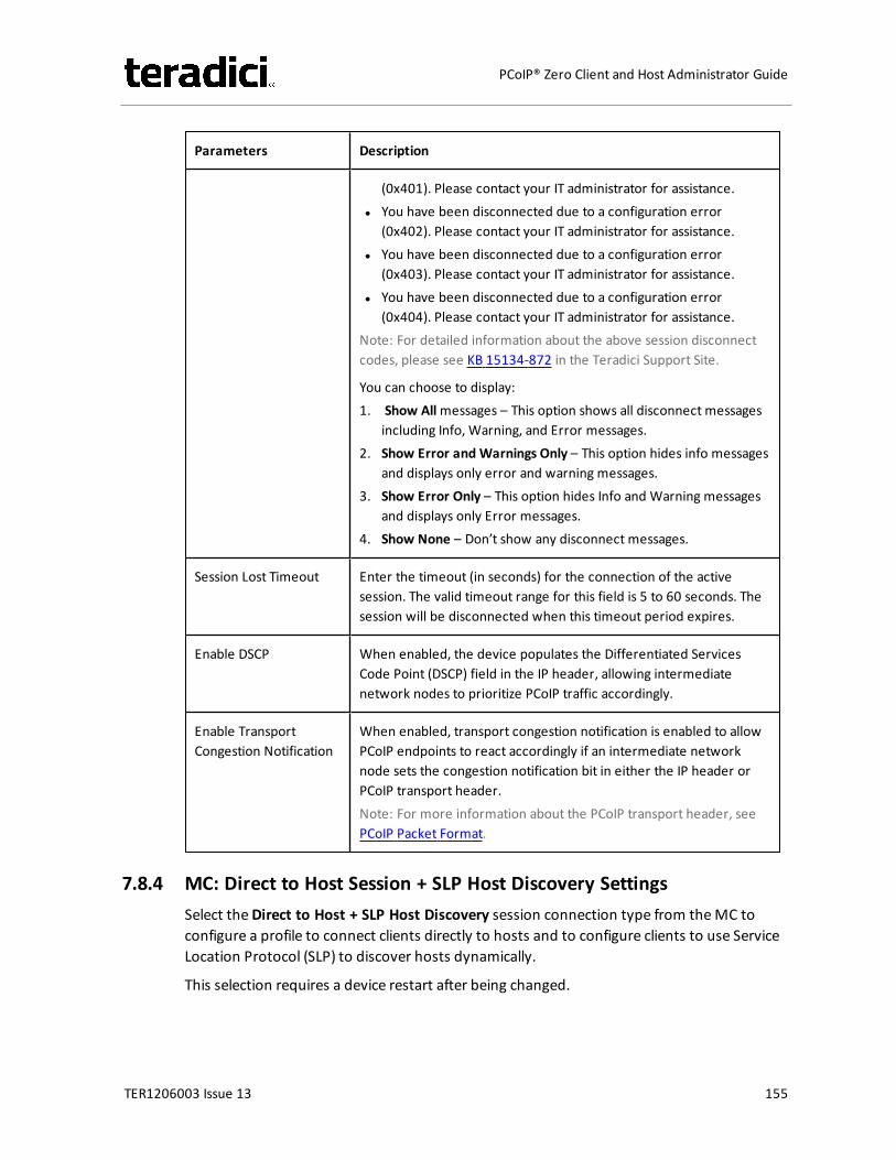
Parameters Description
(0x401). Please contact your IT administrator for assistance.l You have been disconnected due to a configuration error
(0x402). Please contact your IT administrator for assistance.l You have been disconnected due to a configuration error
(0x403). Please contact your IT administrator for assistance.l You have been disconnected due to a configuration error
(0x404). Please contact your IT administrator for assistance.Note: For detailed information about the above session disconnectcodes, please see KB 15134-872 in the Teradici Support Site.
You can choose to display:1. Show Allmessages – This option shows all disconnect messages
including Info, Warning, and Error messages.2. Show Error and Warnings Only – This option hides info messages
and displays only error and warning messages.3. Show Error Only – This option hides Info and Warning messages
and displays only Error messages.4. Show None – Don’t show any disconnect messages.
Session Lost Timeout Enter the timeout (in seconds) for the connection of the activesession. The valid timeout range for this field is 5 to 60 seconds. Thesession will be disconnected when this timeout period expires.
Enable DSCP When enabled, the device populates the Differentiated ServicesCode Point (DSCP) field in the IP header, allowing intermediatenetwork nodes to prioritize PCoIP traffic accordingly.
Enable TransportCongestion Notification
When enabled, transport congestion notification is enabled to allowPCoIP endpoints to react accordingly if an intermediate networknode sets the congestion notification bit in either the IP header orPCoIP transport header.Note: For more information about the PCoIP transport header, seePCoIP Packet Format.
7.8.4 MC: Direct to Host Session + SLP Host Discovery SettingsSelect theDirect to Host + SLP Host Discovery session connection type from theMC toconfigure a profile to connect clients directly to hosts and to configure clients to use ServiceLocation Protocol (SLP) to discover hosts dynamically.
This selection requires a device restart after being changed.
TER1206003 Issue 13 155
PCoIP® Zero Client and Host Administrator Guide
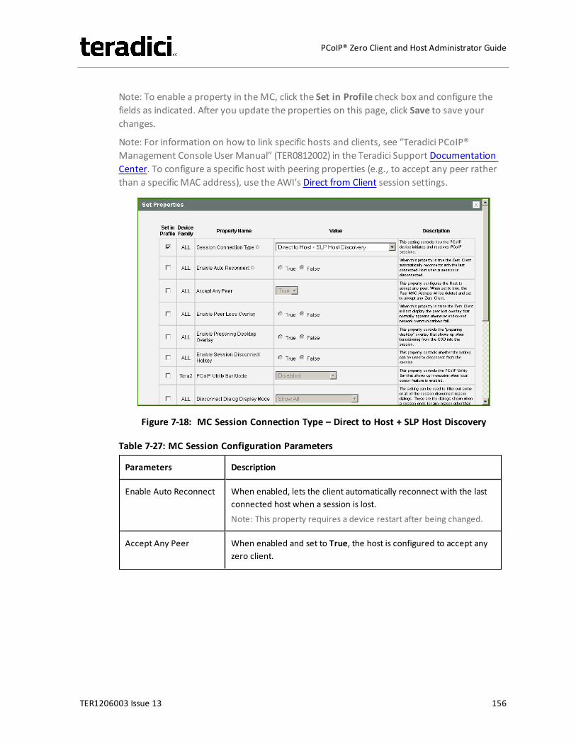
Note: To enable a property in theMC, click the Set in Profile check box and configure thefields as indicated. After you update the properties on this page, click Save to save yourchanges.
Note: For information on how to link specific hosts and clients, see “Teradici PCoIP®Management Console User Manual” (TER0812002) in the Teradici Support DocumentationCenter. To configure a specific host with peering properties (e.g., to accept any peer ratherthan a specific MAC address), use the AWI's Direct from Client session settings.
Figure 7-18: MC Session Connection Type – Direct to Host + SLP Host Discovery
Table 7-27: MC Session Configuration Parameters
Parameters Description
Enable Auto Reconnect When enabled, lets the client automatically reconnect with the lastconnected host when a session is lost.Note: This property requires a device restart after being changed.
Accept Any Peer When enabled and set to True, the host is configured to accept anyzero client.
TER1206003 Issue 13 156
PCoIP® Zero Client and Host Administrator Guide

Parameters Description
Enable Peer LossOverlay
When enabled, the “Network Connection Lost” overlay appears onthe display(s) when a loss of network connectivity is detected.Normal hypervisor scheduling delays can falsely trigger this message.
Note: This option is only available for a zero client. Desktopapplications that require the peer loss notification should re-enablethe feature through the OSD, AWI, or MC.
Enable PreparingDesktop Overlay
When enabled, the "Preparing Desktop" overlay appears on thedisplay(s) when users log in.Note: This overlay provides assurance that login is proceeding if thedesktop takes more than a few seconds to appear.
Enable SessionDisconnect Hotkey
When enabled, users can press the Ctrl+Alt+F12 hotkey sequence topop up the "Zero Client Control Panel" overlay, which lets themdisconnect the current session on the workstation or power off theworkstation.Note: Before users can use this disconnect hotkey sequence, certainother configuration options must be in place. See Disconnectingfrom a Session for details.
PCoIP Utility Bar Mode(Tera2 zero clients only)
When enabled, the PCoIP Utility Bar appears at the top of theprimary display when a user is in session and moves the cursordirectly under the bar. The utility bar can be used to disconnect asession or to shut down a remote workstation. For Direct to Hostsession connection types, Local Cursor and Keyboard must beenabled in order for the zero client to process mouse events for theutility bar. For all connection types, the mouse must be locallyconnected (i.e., not bridged).l Disabled: Disables the PCoIP Utility Bar. Note: (By default, the
utility bar is disabled.)l Enabled: Enables and auto-hides the PCoIP Utility Bar. Users can
show the utility bar by pointing the mouse at the top of thescreen directly under the utility bar. Users can slide the utility barto the right and left at the top of the screen.
l Enabled and Pinned: Enables and pins the PCoIP Utility Bar at thetop of the screen. Users cannot hide the utility bar, but they canslide it to the right and left at the top of the screen.
Note: This feature is configurable from the MC and AWI only. Itrequires firmware version 4.2.0 or newer.
TER1206003 Issue 13 157
PCoIP® Zero Client and Host Administrator Guide
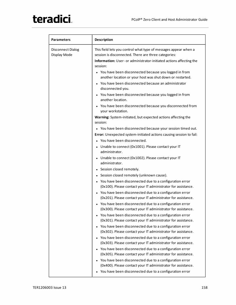
Parameters Description
Disconnect DialogDisplay Mode
This field lets you control what type of messages appear when asession is disconnected. There are three categories:Information: User- or administrator-initiated actions affecting thesession:l You have been disconnected because you logged in from
another location or your host was shut down or restarted.l You have been disconnected because an administrator
disconnected you.l You have been disconnected because you logged in from
another location.l You have been disconnected because you disconnected from
your workstation.Warning: System-initiated, but expected actions affecting thesession:l You have been disconnected because your session timed out.Error: Unexpected system-initiated actions causing session to fail:l You have been disconnected.l Unable to connect (0x1001). Please contact your IT
administrator.l Unable to connect (0x1002). Please contact your IT
administrator.l Session closed remotely.l Session closed remotely (unknown cause).l You have been disconnected due to a configuration error
(0x100). Please contact your IT administrator for assistance.l You have been disconnected due to a configuration error
(0x201). Please contact your IT administrator for assistance.l You have been disconnected due to a configuration error
(0x300). Please contact your IT administrator for assistance.l You have been disconnected due to a configuration error
(0x301). Please contact your IT administrator for assistance.l You have been disconnected due to a configuration error
(0x302). Please contact your IT administrator for assistance.l You have been disconnected due to a configuration error
(0x303). Please contact your IT administrator for assistance.l You have been disconnected due to a configuration error
(0x305). Please contact your IT administrator for assistance.l You have been disconnected due to a configuration error
(0x400). Please contact your IT administrator for assistance.l You have been disconnected due to a configuration error
TER1206003 Issue 13 158
PCoIP® Zero Client and Host Administrator Guide

Parameters Description
(0x401). Please contact your IT administrator for assistance.l You have been disconnected due to a configuration error
(0x402). Please contact your IT administrator for assistance.l You have been disconnected due to a configuration error
(0x403). Please contact your IT administrator for assistance.l You have been disconnected due to a configuration error
(0x404). Please contact your IT administrator for assistance.Note: For detailed information about the above session disconnectcodes, please see KB 15134-872 in the Teradici Support Site.
You can choose to display:1. Show Allmessages – This option shows all disconnect messages
including Info, Warning, and Error messages.2. Show Error and Warnings Only – This option hides info messages
and displays only error and warning messages.3. Show Error Only – This option hides Info and Warning messages
and displays only Error messages.4. Show None – Don’t show any disconnect messages.
Session Lost Timeout Enter the timeout (in seconds) for the connection of the activesession. The valid timeout range for this field is 5 to 60 seconds. Thesession will be disconnected when this timeout period expires.
Enable DSCP When enabled, the device populates the Differentiated ServicesCode Point (DSCP) field in the IP header, allowing intermediatenetwork nodes to prioritize PCoIP traffic accordingly.
Enable TransportCongestion Notification
When enabled, transport congestion notification is enabled to allowPCoIP endpoints to react accordingly if an intermediate networknode sets the congestion notification bit in either the IP header orPCoIP transport header.Note: For more information about the PCoIP transport header, seePCoIP Packet Format.
7.8.5 MC: View Connection Server Session SettingsSelect the View Connection Server session connection type from theMC to configure aprofile to use a View Connection Server to connect clients to a VMware desktop.
This selection requires a device restart after being changed.
Note: To enable a property in theMC, click the Set in Profile check box and configure thefields as indicated. After you update the properties on this page, click Save to save yourchanges.
TER1206003 Issue 13 159
PCoIP® Zero Client and Host Administrator Guide
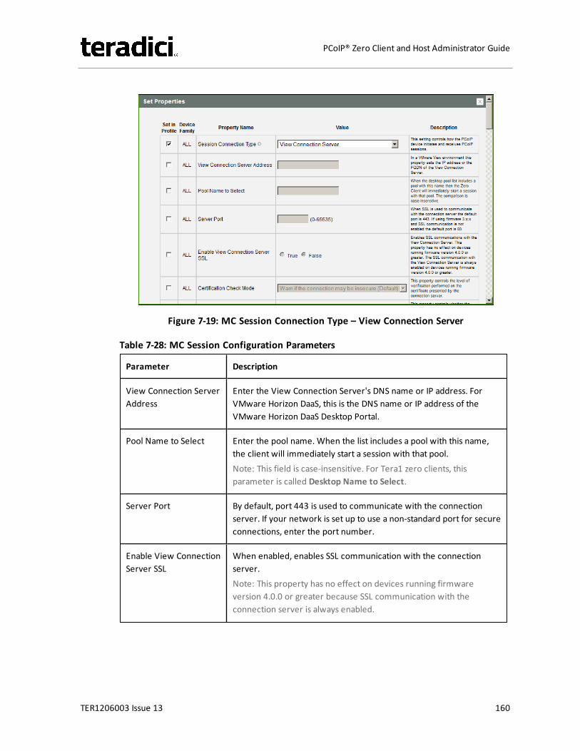
Figure 7-19: MC Session Connection Type – View Connection Server
Table 7-28: MC Session Configuration Parameters
Parameter Description
View Connection ServerAddress
Enter the View Connection Server's DNS name or IP address. ForVMware Horizon DaaS, this is the DNS name or IP address of theVMware Horizon DaaS Desktop Portal.
Pool Name to Select Enter the pool name. When the list includes a pool with this name,the client will immediately start a session with that pool.Note: This field is case-insensitive. For Tera1 zero clients, thisparameter is called Desktop Name to Select.
Server Port By default, port 443 is used to communicate with the connectionserver. If your network is set up to use a non-standard port for secureconnections, enter the port number.
Enable View ConnectionServer SSL
When enabled, enables SSL communication with the connectionserver.Note: This property has no effect on devices running firmwareversion 4.0.0 or greater because SSL communication with theconnection server is always enabled.
TER1206003 Issue 13 160
PCoIP® Zero Client and Host Administrator Guide
Parameter Description
Certification CheckMode
Select the level of verification performed on the certificatepresented by the connection server:l Warn if the connection may be insecure (Default): Configure the
client to display a warning if an unsigned or expired certificate isencountered, or if the certificate is not self-signed and the zeroclient trust store is empty.
l Reject the unverifiable connection (Secure): Configure the clientto reject the connection if a trusted, valid certificate is notinstalled.
l Allow the unverifiable connection (Not Secure): Configure theclient to allow all connections.
Certification CheckLockout Mode
Select whether to lock or unlock Certification Check Mode:l Unlocked: Select this option to allow users to change the
Certification Check Mode setting using the OSD or AWI.l Locked: Select this option to prevent users from changing the
Certification Check Mode setting.
Clear TrustedConnection ServerCache
When enabled, clears the trusted connection server cache.
Auto Connect Mode This field determines the client's auto connect behavior after startup:l Enabled: The client automatically connects with the connection
server after startup and a PCoIP session ends, bypassing the OSDConnect page.
l Disabled: The client does not automatically connect with theconnection server.
l Enabled With Retry On Error: The client will continuouslyattempt to contact the connection server. After a connectionfailure, the client waits before attempting to connect again. Thiswait time increases with each successive failure. The wait intervalis not configurable.Note: Devices running firmware 4.1.1 or lower do not supportRetry On Error behavior and will always perform a single attemptto contact the connection server when this option is selected.
TER1206003 Issue 13 161
PCoIP® Zero Client and Host Administrator Guide
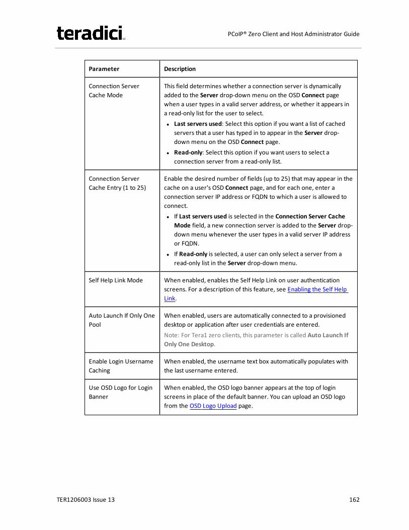
Parameter Description
Connection ServerCache Mode
This field determines whether a connection server is dynamicallyadded to the Server drop-down menu on the OSD Connect pagewhen a user types in a valid server address, or whether it appears ina read-only list for the user to select.l Last servers used: Select this option if you want a list of cached
servers that a user has typed in to appear in the Server drop-down menu on the OSD Connect page.
l Read-only: Select this option if you want users to select aconnection server from a read-only list.
Connection ServerCache Entry (1 to 25)
Enable the desired number of fields (up to 25) that may appear in thecache on a user's OSD Connect page, and for each one, enter aconnection server IP address or FQDN to which a user is allowed toconnect.l If Last servers used is selected in the Connection Server Cache
Mode field, a new connection server is added to the Server drop-down menu whenever the user types in a valid server IP addressor FQDN.
l If Read-only is selected, a user can only select a server from aread-only list in the Server drop-down menu.
Self Help Link Mode When enabled, enables the Self Help Link on user authenticationscreens. For a description of this feature, see Enabling the Self HelpLink.
Auto Launch If Only OnePool
When enabled, users are automatically connected to a provisioneddesktop or application after user credentials are entered.Note: For Tera1 zero clients, this parameter is called Auto Launch IfOnly One Desktop.
Enable Login UsernameCaching
When enabled, the username text box automatically populates withthe last username entered.
Use OSD Logo for LoginBanner
When enabled, the OSD logo banner appears at the top of loginscreens in place of the default banner. You can upload an OSD logofrom the OSD Logo Upload page.
TER1206003 Issue 13 162
PCoIP® Zero Client and Host Administrator Guide
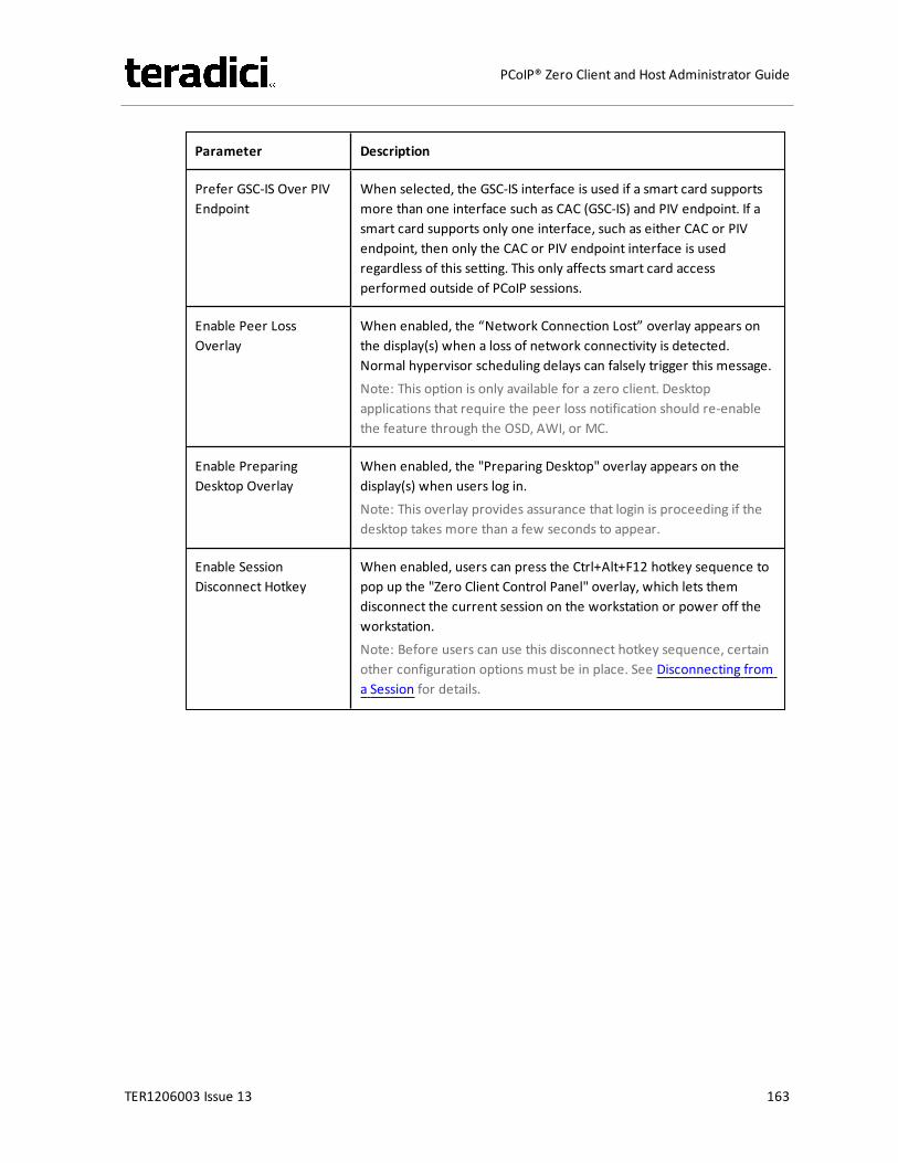
Parameter Description
Prefer GSC-IS Over PIVEndpoint
When selected, the GSC-IS interface is used if a smart card supportsmore than one interface such as CAC (GSC-IS) and PIV endpoint. If asmart card supports only one interface, such as either CAC or PIVendpoint, then only the CAC or PIV endpoint interface is usedregardless of this setting. This only affects smart card accessperformed outside of PCoIP sessions.
Enable Peer LossOverlay
When enabled, the “Network Connection Lost” overlay appears onthe display(s) when a loss of network connectivity is detected.Normal hypervisor scheduling delays can falsely trigger this message.Note: This option is only available for a zero client. Desktopapplications that require the peer loss notification should re-enablethe feature through the OSD, AWI, or MC.
Enable PreparingDesktop Overlay
When enabled, the "Preparing Desktop" overlay appears on thedisplay(s) when users log in.Note: This overlay provides assurance that login is proceeding if thedesktop takes more than a few seconds to appear.
Enable SessionDisconnect Hotkey
When enabled, users can press the Ctrl+Alt+F12 hotkey sequence topop up the "Zero Client Control Panel" overlay, which lets themdisconnect the current session on the workstation or power off theworkstation.Note: Before users can use this disconnect hotkey sequence, certainother configuration options must be in place. See Disconnecting froma Session for details.
TER1206003 Issue 13 163
PCoIP® Zero Client and Host Administrator Guide
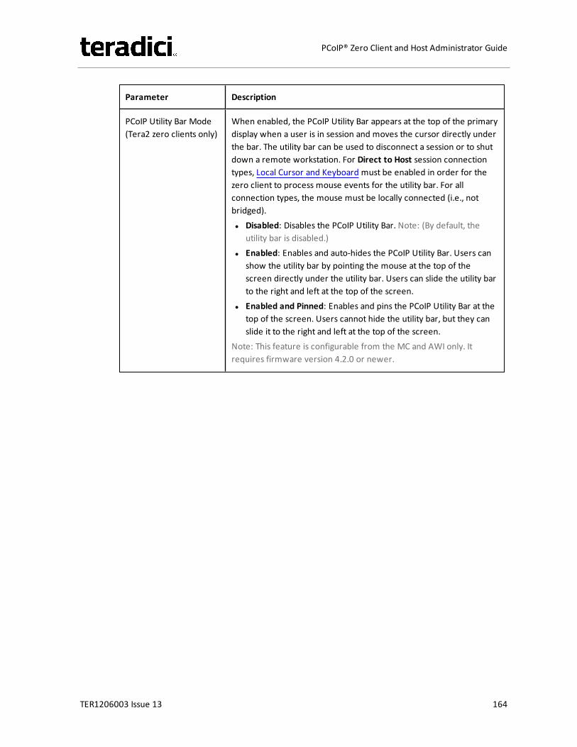
Parameter Description
PCoIP Utility Bar Mode(Tera2 zero clients only)
When enabled, the PCoIP Utility Bar appears at the top of the primarydisplay when a user is in session and moves the cursor directly underthe bar. The utility bar can be used to disconnect a session or to shutdown a remote workstation. For Direct to Host session connectiontypes, Local Cursor and Keyboard must be enabled in order for thezero client to process mouse events for the utility bar. For allconnection types, the mouse must be locally connected (i.e., notbridged).l Disabled: Disables the PCoIP Utility Bar. Note: (By default, the
utility bar is disabled.)l Enabled: Enables and auto-hides the PCoIP Utility Bar. Users can
show the utility bar by pointing the mouse at the top of thescreen directly under the utility bar. Users can slide the utility barto the right and left at the top of the screen.
l Enabled and Pinned: Enables and pins the PCoIP Utility Bar at thetop of the screen. Users cannot hide the utility bar, but they canslide it to the right and left at the top of the screen.
Note: This feature is configurable from the MC and AWI only. Itrequires firmware version 4.2.0 or newer.
TER1206003 Issue 13 164
PCoIP® Zero Client and Host Administrator Guide

Parameter Description
Disconnect Dialog Dis-play Mode
This field lets you control what type of messages appear when asession is disconnected. There are three categories:Information: User- or administrator-initiated actions affecting thesession:l You have been disconnected because you logged in from another
location or your host was shut down or restarted.l You have been disconnected because an administrator
disconnected you.l You have been disconnected because you logged in from another
location.l You have been disconnected because you disconnected from
your workstation.Warning: System-initiated, but expected actions affecting the session:l You have been disconnected because your session timed out.Error: Unexpected system-initiated actions causing session to fail:l You have been disconnected.l Unable to connect (0x1001). Please contact your IT administrator.l Unable to connect (0x1002). Please contact your IT administrator.l Session closed remotely.l Session closed remotely (unknown cause).l You have been disconnected due to a configuration error
(0x100). Please contact your IT administrator for assistance.l You have been disconnected due to a configuration error
(0x201). Please contact your IT administrator for assistance.l You have been disconnected due to a configuration error
(0x300). Please contact your IT administrator for assistance.l You have been disconnected due to a configuration error
(0x301). Please contact your IT administrator for assistance.l You have been disconnected due to a configuration error
(0x302). Please contact your IT administrator for assistance.l You have been disconnected due to a configuration error
(0x303). Please contact your IT administrator for assistance.l You have been disconnected due to a configuration error
(0x305). Please contact your IT administrator for assistance.l You have been disconnected due to a configuration error
(0x400). Please contact your IT administrator for assistance.l You have been disconnected due to a configuration error
(0x401). Please contact your IT administrator for assistance.l You have been disconnected due to a configuration error
TER1206003 Issue 13 165
PCoIP® Zero Client and Host Administrator Guide
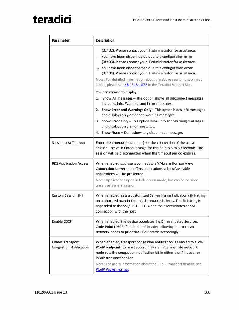
Parameter Description
(0x402). Please contact your IT administrator for assistance.l You have been disconnected due to a configuration error
(0x403). Please contact your IT administrator for assistance.l You have been disconnected due to a configuration error
(0x404). Please contact your IT administrator for assistance.Note: For detailed information about the above session disconnectcodes, please see KB 15134-872 in the Teradici Support Site.
You can choose to display:1. Show Allmessages – This option shows all disconnect messages
including Info, Warning, and Error messages.2. Show Error and Warnings Only – This option hides info messages
and displays only error and warning messages.3. Show Error Only – This option hides Info and Warning messages
and displays only Error messages.4. Show None – Don’t show any disconnect messages.
Session Lost Timeout Enter the timeout (in seconds) for the connection of the activesession. The valid timeout range for this field is 5 to 60 seconds. Thesession will be disconnected when this timeout period expires.
RDS Application Access When enabled and users connect to a VMware Horizon ViewConnection Server that offers applications, a list of availableapplications will be presented.Note: Applications open in full-screen mode, but can be re-sizedonce users are in session.
Custom Session SNI When enabled, sets a customized Server Name Indication (SNI) stringon authorized man-in-the-middle-enabled clients. The SNI string isappended to the SSL/TLS HELLO when the client initates an SSLconnection with the host.
Enable DSCP When enabled, the device populates the Differentiated ServicesCode Point (DSCP) field in the IP header, allowing intermediatenetwork nodes to prioritize PCoIP traffic accordingly.
Enable TransportCongestion Notification
When enabled, transport congestion notification is enabled to allowPCoIP endpoints to react accordingly if an intermediate networknode sets the congestion notification bit in either the IP header orPCoIP transport header.Note: For more information about the PCoIP transport header, seePCoIP Packet Format.
TER1206003 Issue 13 166
PCoIP® Zero Client and Host Administrator Guide
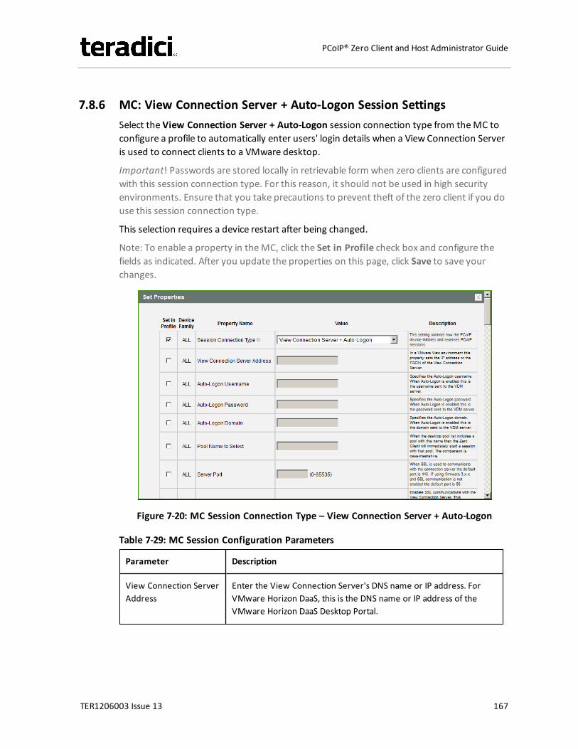
7.8.6 MC: View Connection Server + Auto-Logon Session SettingsSelect the View Connection Server + Auto-Logon session connection type from theMC toconfigure a profile to automatically enter users' login details when a View Connection Serveris used to connect clients to a VMware desktop.
Important! Passwords are stored locally in retrievable form when zero clients are configuredwith this session connection type. For this reason, it should not be used in high securityenvironments. Ensure that you take precautions to prevent theft of the zero client if you douse this session connection type.
This selection requires a device restart after being changed.
Note: To enable a property in theMC, click the Set in Profile check box and configure thefields as indicated. After you update the properties on this page, click Save to save yourchanges.
Figure 7-20: MC Session Connection Type – View Connection Server + Auto-Logon
Table 7-29: MC Session Configuration Parameters
Parameter Description
View Connection ServerAddress
Enter the View Connection Server's DNS name or IP address. ForVMware Horizon DaaS, this is the DNS name or IP address of theVMware Horizon DaaS Desktop Portal.
TER1206003 Issue 13 167
PCoIP® Zero Client and Host Administrator Guide
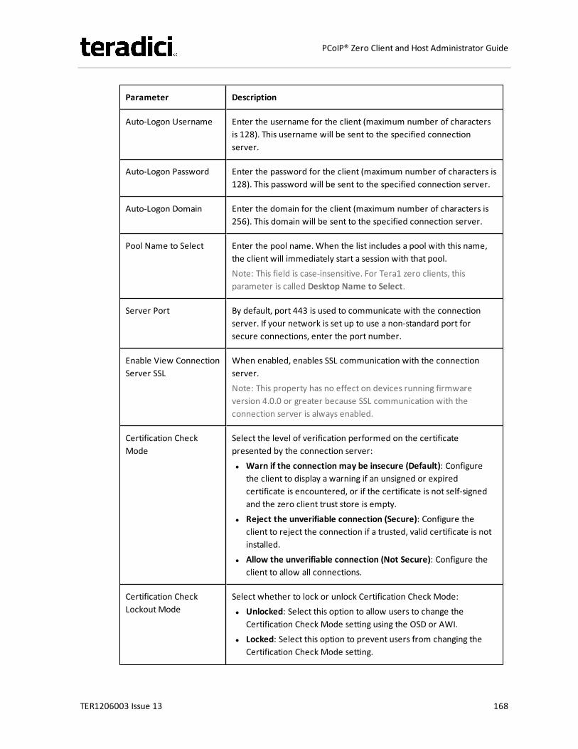
Parameter Description
Auto-Logon Username Enter the username for the client (maximum number of charactersis 128). This username will be sent to the specified connectionserver.
Auto-Logon Password Enter the password for the client (maximum number of characters is128). This password will be sent to the specified connection server.
Auto-Logon Domain Enter the domain for the client (maximum number of characters is256). This domain will be sent to the specified connection server.
Pool Name to Select Enter the pool name. When the list includes a pool with this name,the client will immediately start a session with that pool.Note: This field is case-insensitive. For Tera1 zero clients, thisparameter is called Desktop Name to Select.
Server Port By default, port 443 is used to communicate with the connectionserver. If your network is set up to use a non-standard port forsecure connections, enter the port number.
Enable View ConnectionServer SSL
When enabled, enables SSL communication with the connectionserver.Note: This property has no effect on devices running firmwareversion 4.0.0 or greater because SSL communication with theconnection server is always enabled.
Certification CheckMode
Select the level of verification performed on the certificatepresented by the connection server:l Warn if the connection may be insecure (Default): Configure
the client to display a warning if an unsigned or expiredcertificate is encountered, or if the certificate is not self-signedand the zero client trust store is empty.
l Reject the unverifiable connection (Secure): Configure theclient to reject the connection if a trusted, valid certificate is notinstalled.
l Allow the unverifiable connection (Not Secure): Configure theclient to allow all connections.
Certification CheckLockout Mode
Select whether to lock or unlock Certification Check Mode:l Unlocked: Select this option to allow users to change the
Certification Check Mode setting using the OSD or AWI.l Locked: Select this option to prevent users from changing the
Certification Check Mode setting.
TER1206003 Issue 13 168
PCoIP® Zero Client and Host Administrator Guide
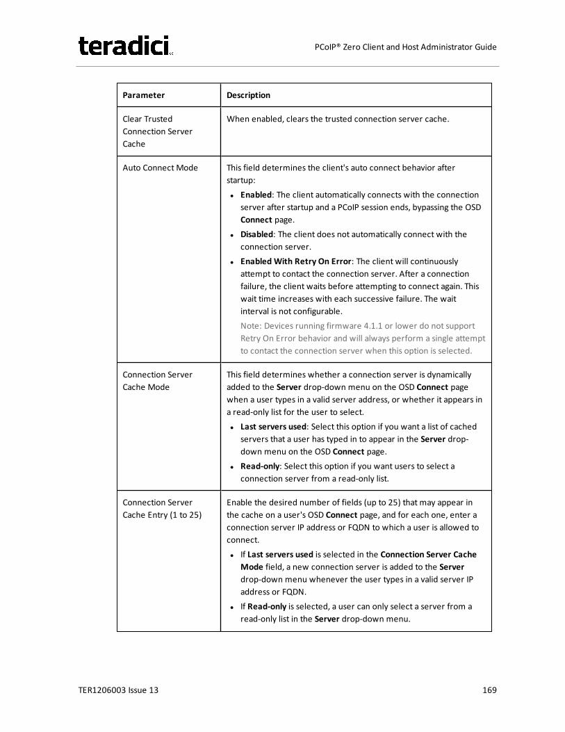
Parameter Description
Clear TrustedConnection ServerCache
When enabled, clears the trusted connection server cache.
Auto Connect Mode This field determines the client's auto connect behavior afterstartup:l Enabled: The client automatically connects with the connection
server after startup and a PCoIP session ends, bypassing the OSDConnect page.
l Disabled: The client does not automatically connect with theconnection server.
l Enabled With Retry On Error: The client will continuouslyattempt to contact the connection server. After a connectionfailure, the client waits before attempting to connect again. Thiswait time increases with each successive failure. The waitinterval is not configurable.Note: Devices running firmware 4.1.1 or lower do not supportRetry On Error behavior and will always perform a single attemptto contact the connection server when this option is selected.
Connection ServerCache Mode
This field determines whether a connection server is dynamicallyadded to the Server drop-down menu on the OSD Connect pagewhen a user types in a valid server address, or whether it appears ina read-only list for the user to select.l Last servers used: Select this option if you want a list of cached
servers that a user has typed in to appear in the Server drop-down menu on the OSD Connect page.
l Read-only: Select this option if you want users to select aconnection server from a read-only list.
Connection ServerCache Entry (1 to 25)
Enable the desired number of fields (up to 25) that may appear inthe cache on a user's OSD Connect page, and for each one, enter aconnection server IP address or FQDN to which a user is allowed toconnect.l If Last servers used is selected in the Connection Server Cache
Mode field, a new connection server is added to the Serverdrop-down menu whenever the user types in a valid server IPaddress or FQDN.
l If Read-only is selected, a user can only select a server from aread-only list in the Server drop-down menu.
TER1206003 Issue 13 169
PCoIP® Zero Client and Host Administrator Guide
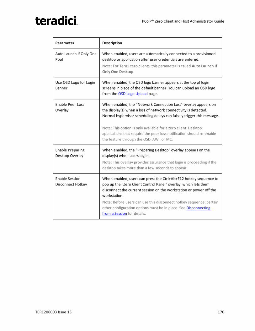
Parameter Description
Auto Launch If Only OnePool
When enabled, users are automatically connected to a provisioneddesktop or application after user credentials are entered.Note: For Tera1 zero clients, this parameter is called Auto Launch IfOnly One Desktop.
Use OSD Logo for LoginBanner
When enabled, the OSD logo banner appears at the top of loginscreens in place of the default banner. You can upload an OSD logofrom the OSD Logo Upload page.
Enable Peer LossOverlay
When enabled, the “Network Connection Lost” overlay appears onthe display(s) when a loss of network connectivity is detected.Normal hypervisor scheduling delays can falsely trigger this message.
Note: This option is only available for a zero client. Desktopapplications that require the peer loss notification should re-enablethe feature through the OSD, AWI, or MC.
Enable PreparingDesktop Overlay
When enabled, the "Preparing Desktop" overlay appears on thedisplay(s) when users log in.Note: This overlay provides assurance that login is proceeding if thedesktop takes more than a few seconds to appear.
Enable SessionDisconnect Hotkey
When enabled, users can press the Ctrl+Alt+F12 hotkey sequence topop up the "Zero Client Control Panel" overlay, which lets themdisconnect the current session on the workstation or power off theworkstation.Note: Before users can use this disconnect hotkey sequence, certainother configuration options must be in place. See Disconnectingfrom a Session for details.
TER1206003 Issue 13 170
PCoIP® Zero Client and Host Administrator Guide

Parameter Description
PCoIP Utility Bar Mode(Tera2 zero clients only)
When enabled, the PCoIP Utility Bar appears at the top of theprimary display when a user is in session and moves the cursordirectly under the bar. The utility bar can be used to disconnect asession or to shut down a remote workstation. For Direct to Hostsession connection types, Local Cursor and Keyboard must beenabled in order for the zero client to process mouse events for theutility bar. For all connection types, the mouse must be locallyconnected (i.e., not bridged).l Disabled: Disables the PCoIP Utility Bar. Note: (By default, the
utility bar is disabled.)l Enabled: Enables and auto-hides the PCoIP Utility Bar. Users can
show the utility bar by pointing the mouse at the top of thescreen directly under the utility bar. Users can slide the utility barto the right and left at the top of the screen.
l Enabled and Pinned: Enables and pins the PCoIP Utility Bar at thetop of the screen. Users cannot hide the utility bar, but they canslide it to the right and left at the top of the screen.
Note: This feature is configurable from the MC and AWI only. Itrequires firmware version 4.2.0 or newer.
TER1206003 Issue 13 171
PCoIP® Zero Client and Host Administrator Guide
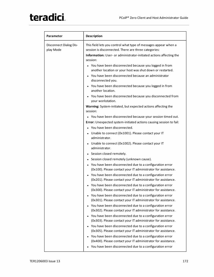
Parameter Description
Disconnect Dialog Dis-play Mode
This field lets you control what type of messages appear when asession is disconnected. There are three categories:Information: User- or administrator-initiated actions affecting thesession:l You have been disconnected because you logged in from
another location or your host was shut down or restarted.l You have been disconnected because an administrator
disconnected you.l You have been disconnected because you logged in from
another location.l You have been disconnected because you disconnected from
your workstation.Warning: System-initiated, but expected actions affecting thesession:l You have been disconnected because your session timed out.Error: Unexpected system-initiated actions causing session to fail:l You have been disconnected.l Unable to connect (0x1001). Please contact your IT
administrator.l Unable to connect (0x1002). Please contact your IT
administrator.l Session closed remotely.l Session closed remotely (unknown cause).l You have been disconnected due to a configuration error
(0x100). Please contact your IT administrator for assistance.l You have been disconnected due to a configuration error
(0x201). Please contact your IT administrator for assistance.l You have been disconnected due to a configuration error
(0x300). Please contact your IT administrator for assistance.l You have been disconnected due to a configuration error
(0x301). Please contact your IT administrator for assistance.l You have been disconnected due to a configuration error
(0x302). Please contact your IT administrator for assistance.l You have been disconnected due to a configuration error
(0x303). Please contact your IT administrator for assistance.l You have been disconnected due to a configuration error
(0x305). Please contact your IT administrator for assistance.l You have been disconnected due to a configuration error
(0x400). Please contact your IT administrator for assistance.l You have been disconnected due to a configuration error
TER1206003 Issue 13 172
PCoIP® Zero Client and Host Administrator Guide

Parameter Description
(0x401). Please contact your IT administrator for assistance.l You have been disconnected due to a configuration error
(0x402). Please contact your IT administrator for assistance.l You have been disconnected due to a configuration error
(0x403). Please contact your IT administrator for assistance.l You have been disconnected due to a configuration error
(0x404). Please contact your IT administrator for assistance.Note: For detailed information about the above session disconnectcodes, please see KB 15134-872 in the Teradici Support Site.
You can choose to display:1. Show Allmessages – This option shows all disconnect messages
including Info, Warning, and Error messages.2. Show Error and Warnings Only – This option hides info messages
and displays only error and warning messages.3. Show Error Only – This option hides Info and Warning messages
and displays only Error messages.4. Show None – Don’t show any disconnect messages.
Session Lost Timeout Enter the timeout (in seconds) for the connection of the activesession. The valid timeout range for this field is 5 to 60 seconds. Thesession will be disconnected when this timeout period expires.
RDS Application Access When enabled and users connect to a VMware Horizon ViewConnection Server that offers applications, a list of availableapplications will be presented.Note: Applications open in full-screen mode, but can be re-sizedonce users are in session.
Custom Session SNI When enabled, sets a customized Server Name Indication (SNI) stringon authorized man-in-the-middle-enabled clients. The SNI string isappended to the SSL/TLS HELLO when the client initates an SSLconnection with the host.
Enable DSCP When enabled, the device populates the Differentiated ServicesCode Point (DSCP) field in the IP header, allowing intermediatenetwork nodes to prioritize PCoIP traffic accordingly.
TER1206003 Issue 13 173
PCoIP® Zero Client and Host Administrator Guide
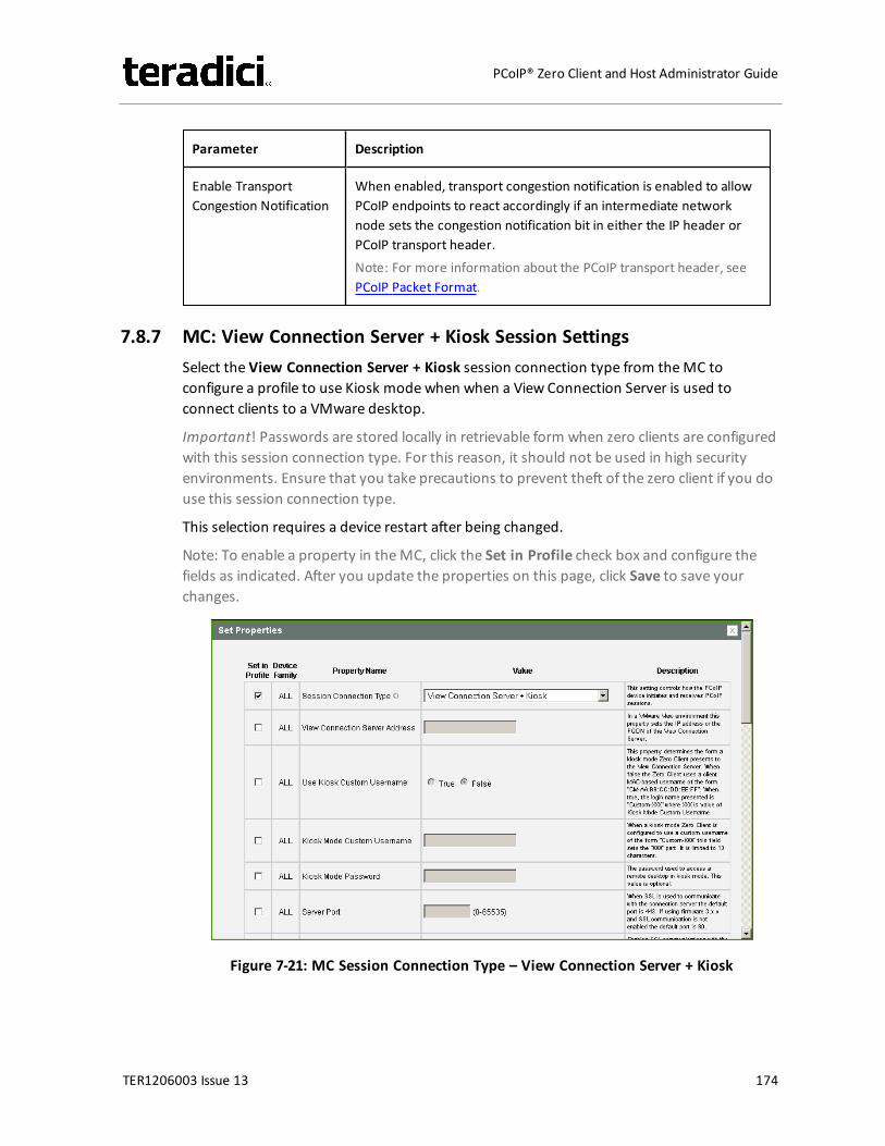
Parameter Description
Enable TransportCongestion Notification
When enabled, transport congestion notification is enabled to allowPCoIP endpoints to react accordingly if an intermediate networknode sets the congestion notification bit in either the IP header orPCoIP transport header.Note: For more information about the PCoIP transport header, seePCoIP Packet Format.
7.8.7 MC: View Connection Server + Kiosk Session SettingsSelect the View Connection Server + Kiosk session connection type from theMC toconfigure a profile to use Kiosk modewhen when a View Connection Server is used toconnect clients to a VMware desktop.
Important! Passwords are stored locally in retrievable form when zero clients are configuredwith this session connection type. For this reason, it should not be used in high securityenvironments. Ensure that you take precautions to prevent theft of the zero client if you douse this session connection type.
This selection requires a device restart after being changed.
Note: To enable a property in theMC, click the Set in Profile check box and configure thefields as indicated. After you update the properties on this page, click Save to save yourchanges.
Figure 7-21: MC Session Connection Type – View Connection Server + Kiosk
TER1206003 Issue 13 174
PCoIP® Zero Client and Host Administrator Guide
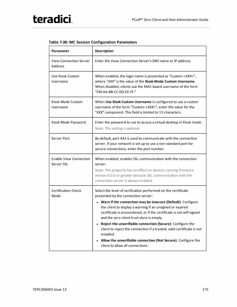
Table 7-30: MC Session Configuration Parameters
Parameter Description
View Connection ServerAddress
Enter the View Connection Server's DNS name or IP address.
Use Kiosk CustomUsername
When enabled, the login name is presented as "Custom-<XXX>",where "XXX" is the value of the KioskMode Custom Username.When disabled, clients use the MAC-based username of the form"CM-AA:BB:CC:DD:EE:FF."
Kiosk Mode CustomUsername
When Use Kiosk Custom Username is configured to use a customusername of the form "Custom-<XXX>", enter the value for the"XXX" component. This field is limited to 13 characters.
Kiosk Mode Password Enter the password to use to access a virtual desktop in Kiosk mode.Note: This setting is optional.
Server Port By default, port 443 is used to communicate with the connectionserver. If your network is set up to use a non-standard port forsecure connections, enter the port number.
Enable View ConnectionServer SSL
When enabled, enables SSL communication with the connectionserver.Note: This property has no effect on devices running firmwareversion 4.0.0 or greater because SSL communication with theconnection server is always enabled.
Certification CheckMode
Select the level of verification performed on the certificatepresented by the connection server:l Warn if the connection may be insecure (Default): Configure
the client to display a warning if an unsigned or expiredcertificate is encountered, or if the certificate is not self-signedand the zero client trust store is empty.
l Reject the unverifiable connection (Secure): Configure theclient to reject the connection if a trusted, valid certificate is notinstalled.
l Allow the unverifiable connection (Not Secure): Configure theclient to allow all connections.
TER1206003 Issue 13 175
PCoIP® Zero Client and Host Administrator Guide
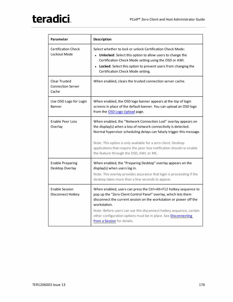
Parameter Description
Certification CheckLockout Mode
Select whether to lock or unlock Certification Check Mode:l Unlocked: Select this option to allow users to change the
Certification Check Mode setting using the OSD or AWI.l Locked: Select this option to prevent users from changing the
Certification Check Mode setting.
Clear TrustedConnection ServerCache
When enabled, clears the trusted connection server cache.
Use OSD Logo for LoginBanner
When enabled, the OSD logo banner appears at the top of loginscreens in place of the default banner. You can upload an OSD logofrom the OSD Logo Upload page.
Enable Peer LossOverlay
When enabled, the “Network Connection Lost” overlay appears onthe display(s) when a loss of network connectivity is detected.Normal hypervisor scheduling delays can falsely trigger this message.
Note: This option is only available for a zero client. Desktopapplications that require the peer loss notification should re-enablethe feature through the OSD, AWI, or MC.
Enable PreparingDesktop Overlay
When enabled, the "Preparing Desktop" overlay appears on thedisplay(s) when users log in.Note: This overlay provides assurance that login is proceeding if thedesktop takes more than a few seconds to appear.
Enable SessionDisconnect Hotkey
When enabled, users can press the Ctrl+Alt+F12 hotkey sequence topop up the "Zero Client Control Panel" overlay, which lets themdisconnect the current session on the workstation or power off theworkstation.Note: Before users can use this disconnect hotkey sequence, certainother configuration options must be in place. See Disconnectingfrom a Session for details.
TER1206003 Issue 13 176
PCoIP® Zero Client and Host Administrator Guide

Parameter Description
PCoIP Utility Bar Mode(Tera2 zero clients only)
When enabled, the PCoIP Utility Bar appears at the top of theprimary display when a user is in session and moves the cursordirectly under the bar. The utility bar can be used to disconnect asession or to shut down a remote workstation. For Direct to Hostsession connection types, Local Cursor and Keyboard must beenabled in order for the zero client to process mouse events for theutility bar. For all connection types, the mouse must be locallyconnected (i.e., not bridged).l Disabled: Disables the PCoIP Utility Bar. Note: (By default, the
utility bar is disabled.)l Enabled: Enables and auto-hides the PCoIP Utility Bar. Users can
show the utility bar by pointing the mouse at the top of thescreen directly under the utility bar. Users can slide the utility barto the right and left at the top of the screen.
l Enabled and Pinned: Enables and pins the PCoIP Utility Bar at thetop of the screen. Users cannot hide the utility bar, but they canslide it to the right and left at the top of the screen.
Note: This feature is configurable from the MC and AWI only. Itrequires firmware version 4.2.0 or newer.
TER1206003 Issue 13 177
PCoIP® Zero Client and Host Administrator Guide

Parameter Description
Disconnect Dialog Dis-play Mode
This field lets you control what type of messages appear when asession is disconnected. There are three categories:Information: User- or administrator-initiated actions affecting thesession:l You have been disconnected because you logged in from
another location or your host was shut down or restarted.l You have been disconnected because an administrator
disconnected you.l You have been disconnected because you logged in from
another location.l You have been disconnected because you disconnected from
your workstation.Warning: System-initiated, but expected actions affecting thesession:l You have been disconnected because your session timed out.Error: Unexpected system-initiated actions causing session to fail:l You have been disconnected.l Unable to connect (0x1001). Please contact your IT
administrator.l Unable to connect (0x1002). Please contact your IT
administrator.l Session closed remotely.l Session closed remotely (unknown cause).l You have been disconnected due to a configuration error
(0x100). Please contact your IT administrator for assistance.l You have been disconnected due to a configuration error
(0x201). Please contact your IT administrator for assistance.l You have been disconnected due to a configuration error
(0x300). Please contact your IT administrator for assistance.l You have been disconnected due to a configuration error
(0x301). Please contact your IT administrator for assistance.l You have been disconnected due to a configuration error
(0x302). Please contact your IT administrator for assistance.l You have been disconnected due to a configuration error
(0x303). Please contact your IT administrator for assistance.l You have been disconnected due to a configuration error
(0x305). Please contact your IT administrator for assistance.l You have been disconnected due to a configuration error
(0x400). Please contact your IT administrator for assistance.l You have been disconnected due to a configuration error
TER1206003 Issue 13 178
PCoIP® Zero Client and Host Administrator Guide

Parameter Description
(0x401). Please contact your IT administrator for assistance.l You have been disconnected due to a configuration error
(0x402). Please contact your IT administrator for assistance.l You have been disconnected due to a configuration error
(0x403). Please contact your IT administrator for assistance.l You have been disconnected due to a configuration error
(0x404). Please contact your IT administrator for assistance.Note: For detailed information about the above session disconnectcodes, please see KB 15134-872 in the Teradici Support Site.
You can choose to display:1. Show Allmessages – This option shows all disconnect messages
including Info, Warning, and Error messages.2. Show Error and Warnings Only – This option hides info messages
and displays only error and warning messages.3. Show Error Only – This option hides Info and Warning messages
and displays only Error messages.4. Show None – Don’t show any disconnect messages.
Session Lost Timeout Enter the timeout (in seconds) for the connection of the activesession. The valid timeout range for this field is 5 to 60 seconds. Thesession will be disconnected when this timeout period expires.
RDS Application Access When enabled and users connect to a VMware Horizon ViewConnection Server that offers applications, a list of availableapplications will be presented.Note: Applications open in full-screen mode, but can be re-sizedonce users are in session.
Custom Session SNI When enabled, sets a customized Server Name Indication (SNI) stringon authorized man-in-the-middle-enabled clients. The SNI string isappended to the SSL/TLS HELLO when the client initates an SSLconnection with the host.
Enable DSCP When enabled, the device populates the Differentiated ServicesCode Point (DSCP) field in the IP header, allowing intermediatenetwork nodes to prioritize PCoIP traffic accordingly.
TER1206003 Issue 13 179
PCoIP® Zero Client and Host Administrator Guide
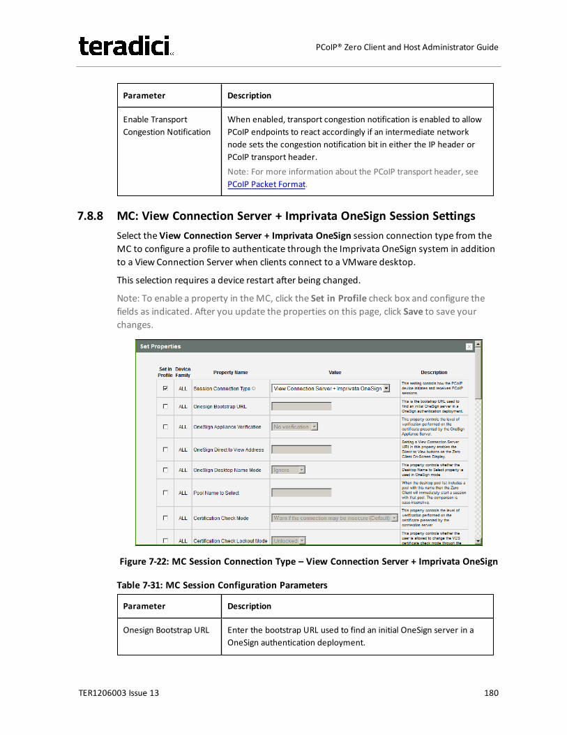
Parameter Description
Enable TransportCongestion Notification
When enabled, transport congestion notification is enabled to allowPCoIP endpoints to react accordingly if an intermediate networknode sets the congestion notification bit in either the IP header orPCoIP transport header.Note: For more information about the PCoIP transport header, seePCoIP Packet Format.
7.8.8 MC: View Connection Server + Imprivata OneSign Session SettingsSelect the View Connection Server + Imprivata OneSign session connection type from theMC to configure a profile to authenticate through the Imprivata OneSign system in additionto a View Connection Server when clients connect to a VMware desktop.
This selection requires a device restart after being changed.
Note: To enable a property in theMC, click the Set in Profile check box and configure thefields as indicated. After you update the properties on this page, click Save to save yourchanges.
Figure 7-22: MC Session Connection Type – View Connection Server + Imprivata OneSign
Table 7-31: MC Session Configuration Parameters
Parameter Description
Onesign Bootstrap URL Enter the bootstrap URL used to find an initial OneSign server in aOneSign authentication deployment.
TER1206003 Issue 13 180
PCoIP® Zero Client and Host Administrator Guide
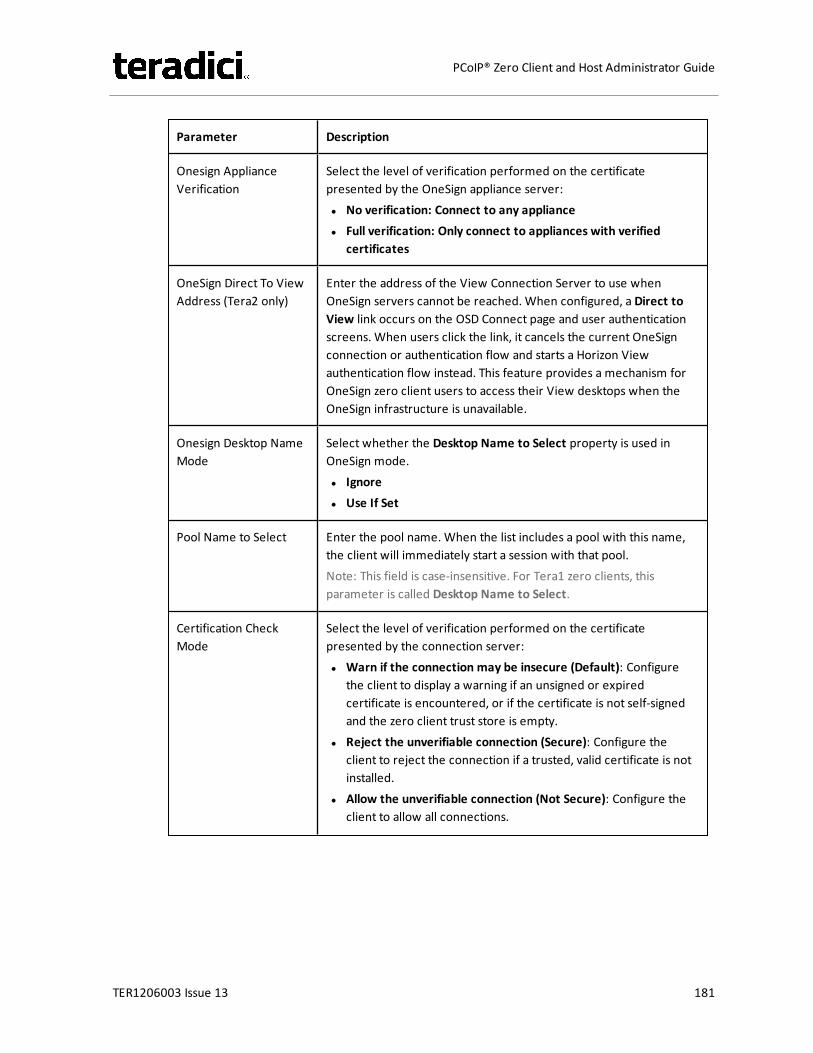
Parameter Description
Onesign ApplianceVerification
Select the level of verification performed on the certificatepresented by the OneSign appliance server:l No verification: Connect to any appliancel Full verification: Only connect to appliances with verified
certificates
OneSign Direct To ViewAddress (Tera2 only)
Enter the address of the View Connection Server to use whenOneSign servers cannot be reached. When configured, a Direct toView link occurs on the OSD Connect page and user authenticationscreens. When users click the link, it cancels the current OneSignconnection or authentication flow and starts a Horizon Viewauthentication flow instead. This feature provides a mechanism forOneSign zero client users to access their View desktops when theOneSign infrastructure is unavailable.
Onesign Desktop NameMode
Select whether the Desktop Name to Select property is used inOneSign mode.l Ignorel Use If Set
Pool Name to Select Enter the pool name. When the list includes a pool with this name,the client will immediately start a session with that pool.Note: This field is case-insensitive. For Tera1 zero clients, thisparameter is called Desktop Name to Select.
Certification CheckMode
Select the level of verification performed on the certificatepresented by the connection server:l Warn if the connection may be insecure (Default): Configure
the client to display a warning if an unsigned or expiredcertificate is encountered, or if the certificate is not self-signedand the zero client trust store is empty.
l Reject the unverifiable connection (Secure): Configure theclient to reject the connection if a trusted, valid certificate is notinstalled.
l Allow the unverifiable connection (Not Secure): Configure theclient to allow all connections.
TER1206003 Issue 13 181
PCoIP® Zero Client and Host Administrator Guide
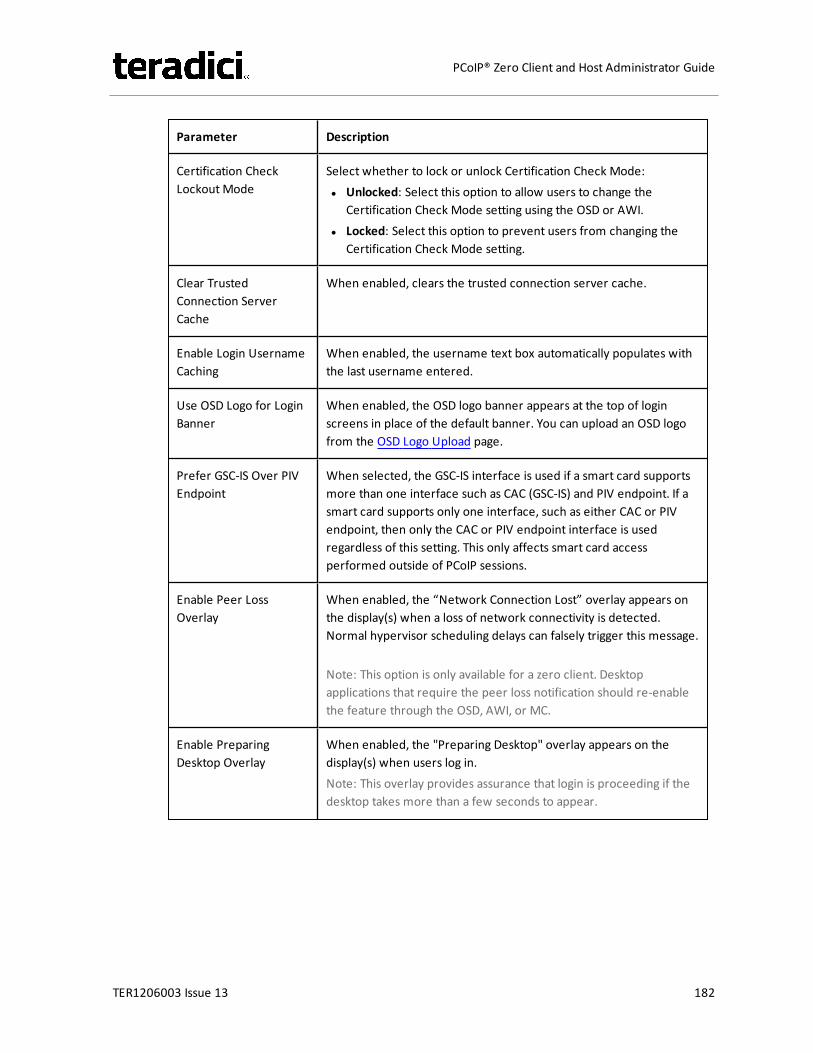
Parameter Description
Certification CheckLockout Mode
Select whether to lock or unlock Certification Check Mode:l Unlocked: Select this option to allow users to change the
Certification Check Mode setting using the OSD or AWI.l Locked: Select this option to prevent users from changing the
Certification Check Mode setting.
Clear TrustedConnection ServerCache
When enabled, clears the trusted connection server cache.
Enable Login UsernameCaching
When enabled, the username text box automatically populates withthe last username entered.
Use OSD Logo for LoginBanner
When enabled, the OSD logo banner appears at the top of loginscreens in place of the default banner. You can upload an OSD logofrom the OSD Logo Upload page.
Prefer GSC-IS Over PIVEndpoint
When selected, the GSC-IS interface is used if a smart card supportsmore than one interface such as CAC (GSC-IS) and PIV endpoint. If asmart card supports only one interface, such as either CAC or PIVendpoint, then only the CAC or PIV endpoint interface is usedregardless of this setting. This only affects smart card accessperformed outside of PCoIP sessions.
Enable Peer LossOverlay
When enabled, the “Network Connection Lost” overlay appears onthe display(s) when a loss of network connectivity is detected.Normal hypervisor scheduling delays can falsely trigger this message.
Note: This option is only available for a zero client. Desktopapplications that require the peer loss notification should re-enablethe feature through the OSD, AWI, or MC.
Enable PreparingDesktop Overlay
When enabled, the "Preparing Desktop" overlay appears on thedisplay(s) when users log in.Note: This overlay provides assurance that login is proceeding if thedesktop takes more than a few seconds to appear.
TER1206003 Issue 13 182
PCoIP® Zero Client and Host Administrator Guide
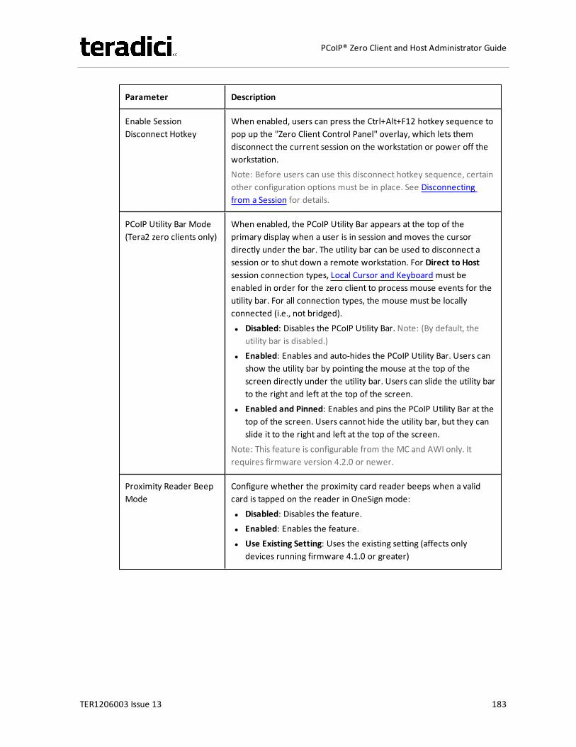
Parameter Description
Enable SessionDisconnect Hotkey
When enabled, users can press the Ctrl+Alt+F12 hotkey sequence topop up the "Zero Client Control Panel" overlay, which lets themdisconnect the current session on the workstation or power off theworkstation.Note: Before users can use this disconnect hotkey sequence, certainother configuration options must be in place. See Disconnectingfrom a Session for details.
PCoIP Utility Bar Mode(Tera2 zero clients only)
When enabled, the PCoIP Utility Bar appears at the top of theprimary display when a user is in session and moves the cursordirectly under the bar. The utility bar can be used to disconnect asession or to shut down a remote workstation. For Direct to Hostsession connection types, Local Cursor and Keyboard must beenabled in order for the zero client to process mouse events for theutility bar. For all connection types, the mouse must be locallyconnected (i.e., not bridged).l Disabled: Disables the PCoIP Utility Bar. Note: (By default, the
utility bar is disabled.)l Enabled: Enables and auto-hides the PCoIP Utility Bar. Users can
show the utility bar by pointing the mouse at the top of thescreen directly under the utility bar. Users can slide the utility barto the right and left at the top of the screen.
l Enabled and Pinned: Enables and pins the PCoIP Utility Bar at thetop of the screen. Users cannot hide the utility bar, but they canslide it to the right and left at the top of the screen.
Note: This feature is configurable from the MC and AWI only. Itrequires firmware version 4.2.0 or newer.
Proximity Reader BeepMode
Configure whether the proximity card reader beeps when a validcard is tapped on the reader in OneSign mode:l Disabled: Disables the feature.l Enabled: Enables the feature.l Use Existing Setting: Uses the existing setting (affects only
devices running firmware 4.1.0 or greater)
TER1206003 Issue 13 183
PCoIP® Zero Client and Host Administrator Guide
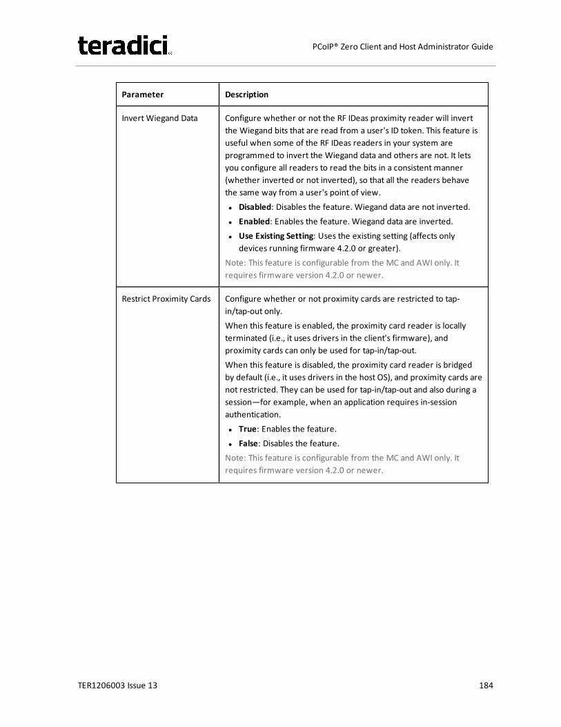
Parameter Description
Invert Wiegand Data Configure whether or not the RF IDeas proximity reader will invertthe Wiegand bits that are read from a user's ID token. This feature isuseful when some of the RF IDeas readers in your system areprogrammed to invert the Wiegand data and others are not. It letsyou configure all readers to read the bits in a consistent manner(whether inverted or not inverted), so that all the readers behavethe same way from a user's point of view.l Disabled: Disables the feature. Wiegand data are not inverted.l Enabled: Enables the feature. Wiegand data are inverted.l Use Existing Setting: Uses the existing setting (affects only
devices running firmware 4.2.0 or greater).Note: This feature is configurable from the MC and AWI only. Itrequires firmware version 4.2.0 or newer.
Restrict Proximity Cards Configure whether or not proximity cards are restricted to tap-in/tap-out only.When this feature is enabled, the proximity card reader is locallyterminated (i.e., it uses drivers in the client's firmware), andproximity cards can only be used for tap-in/tap-out.When this feature is disabled, the proximity card reader is bridgedby default (i.e., it uses drivers in the host OS), and proximity cards arenot restricted. They can be used for tap-in/tap-out and also during asession—for example, when an application requires in-sessionauthentication.l True: Enables the feature.l False: Disables the feature.Note: This feature is configurable from the MC and AWI only. Itrequires firmware version 4.2.0 or newer.
TER1206003 Issue 13 184
PCoIP® Zero Client and Host Administrator Guide

Parameter Description
Disconnect Dialog Dis-play Mode
This field lets you control what type of messages appear when asession is disconnected. There are three categories:Information: User- or administrator-initiated actions affecting thesession:l You have been disconnected because you logged in from
another location or your host was shut down or restarted.l You have been disconnected because an administrator
disconnected you.l You have been disconnected because you logged in from
another location.l You have been disconnected because you disconnected from
your workstation.Warning: System-initiated, but expected actions affecting thesession:l You have been disconnected because your session timed out.Error: Unexpected system-initiated actions causing session to fail:l You have been disconnected.l Unable to connect (0x1001). Please contact your IT
administrator.l Unable to connect (0x1002). Please contact your IT
administrator.l Session closed remotely.l Session closed remotely (unknown cause).l You have been disconnected due to a configuration error
(0x100). Please contact your IT administrator for assistance.l You have been disconnected due to a configuration error
(0x201). Please contact your IT administrator for assistance.l You have been disconnected due to a configuration error
(0x300). Please contact your IT administrator for assistance.l You have been disconnected due to a configuration error
(0x301). Please contact your IT administrator for assistance.l You have been disconnected due to a configuration error
(0x302). Please contact your IT administrator for assistance.l You have been disconnected due to a configuration error
(0x303). Please contact your IT administrator for assistance.l You have been disconnected due to a configuration error
(0x305). Please contact your IT administrator for assistance.l You have been disconnected due to a configuration error
(0x400). Please contact your IT administrator for assistance.l You have been disconnected due to a configuration error
TER1206003 Issue 13 185
PCoIP® Zero Client and Host Administrator Guide
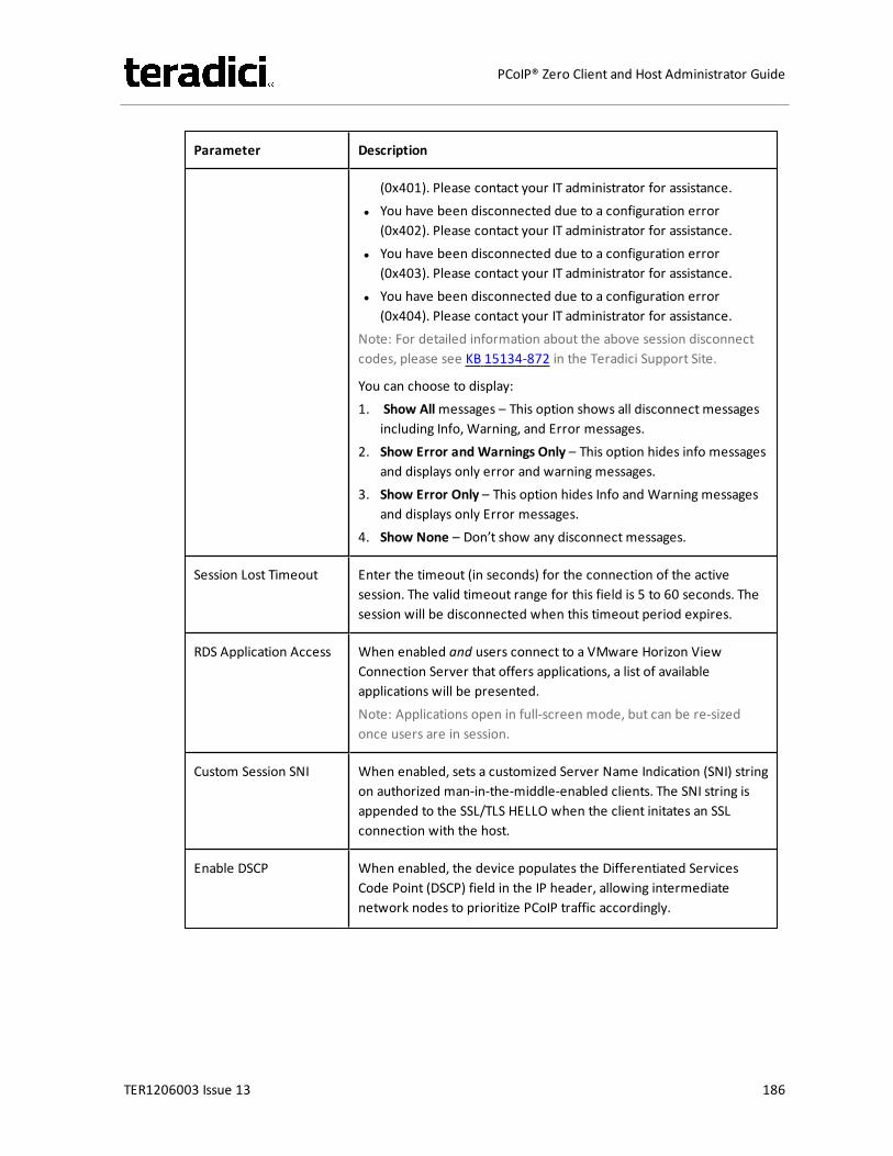
Parameter Description
(0x401). Please contact your IT administrator for assistance.l You have been disconnected due to a configuration error
(0x402). Please contact your IT administrator for assistance.l You have been disconnected due to a configuration error
(0x403). Please contact your IT administrator for assistance.l You have been disconnected due to a configuration error
(0x404). Please contact your IT administrator for assistance.Note: For detailed information about the above session disconnectcodes, please see KB 15134-872 in the Teradici Support Site.
You can choose to display:1. Show Allmessages – This option shows all disconnect messages
including Info, Warning, and Error messages.2. Show Error and Warnings Only – This option hides info messages
and displays only error and warning messages.3. Show Error Only – This option hides Info and Warning messages
and displays only Error messages.4. Show None – Don’t show any disconnect messages.
Session Lost Timeout Enter the timeout (in seconds) for the connection of the activesession. The valid timeout range for this field is 5 to 60 seconds. Thesession will be disconnected when this timeout period expires.
RDS Application Access When enabled and users connect to a VMware Horizon ViewConnection Server that offers applications, a list of availableapplications will be presented.Note: Applications open in full-screen mode, but can be re-sizedonce users are in session.
Custom Session SNI When enabled, sets a customized Server Name Indication (SNI) stringon authorized man-in-the-middle-enabled clients. The SNI string isappended to the SSL/TLS HELLO when the client initates an SSLconnection with the host.
Enable DSCP When enabled, the device populates the Differentiated ServicesCode Point (DSCP) field in the IP header, allowing intermediatenetwork nodes to prioritize PCoIP traffic accordingly.
TER1206003 Issue 13 186
PCoIP® Zero Client and Host Administrator Guide
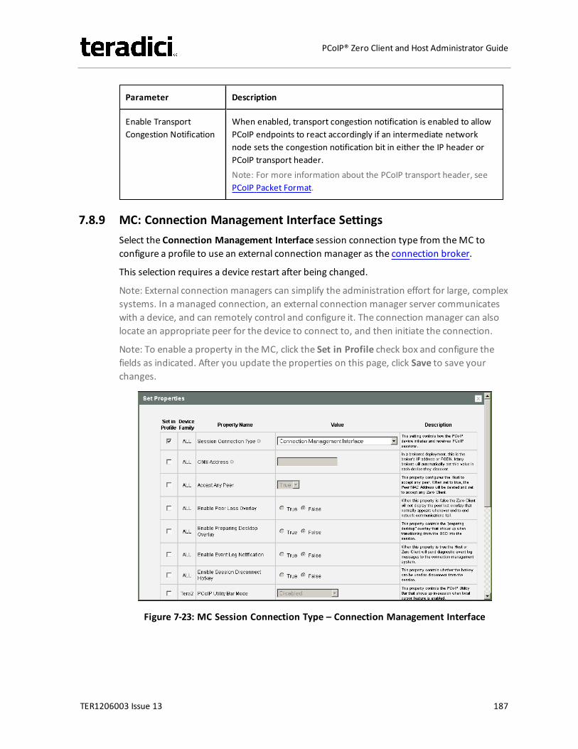
Parameter Description
Enable TransportCongestion Notification
When enabled, transport congestion notification is enabled to allowPCoIP endpoints to react accordingly if an intermediate networknode sets the congestion notification bit in either the IP header orPCoIP transport header.Note: For more information about the PCoIP transport header, seePCoIP Packet Format.
7.8.9 MC: Connection Management Interface SettingsSelect the Connection Management Interface session connection type from theMC toconfigure a profile to use an external connection manager as the connection broker.
This selection requires a device restart after being changed.
Note: External connection managers can simplify the administration effort for large, complexsystems. In a managed connection, an external connection manager server communicateswith a device, and can remotely control and configure it. The connection manager can alsolocate an appropriate peer for the device to connect to, and then initiate the connection.
Note: To enable a property in theMC, click the Set in Profile check box and configure thefields as indicated. After you update the properties on this page, click Save to save yourchanges.
Figure 7-23: MC Session Connection Type – Connection Management Interface
TER1206003 Issue 13 187
PCoIP® Zero Client and Host Administrator Guide
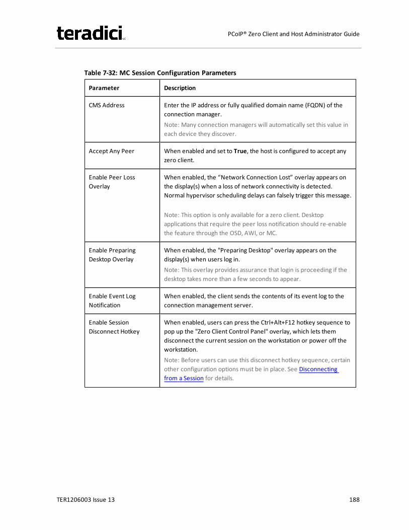
Table 7-32: MC Session Configuration Parameters
Parameter Description
CMS Address Enter the IP address or fully qualified domain name (FQDN) of theconnection manager.Note: Many connection managers will automatically set this value ineach device they discover.
Accept Any Peer When enabled and set to True, the host is configured to accept anyzero client.
Enable Peer LossOverlay
When enabled, the “Network Connection Lost” overlay appears onthe display(s) when a loss of network connectivity is detected.Normal hypervisor scheduling delays can falsely trigger this message.
Note: This option is only available for a zero client. Desktopapplications that require the peer loss notification should re-enablethe feature through the OSD, AWI, or MC.
Enable PreparingDesktop Overlay
When enabled, the "Preparing Desktop" overlay appears on thedisplay(s) when users log in.Note: This overlay provides assurance that login is proceeding if thedesktop takes more than a few seconds to appear.
Enable Event LogNotification
When enabled, the client sends the contents of its event log to theconnection management server.
Enable SessionDisconnect Hotkey
When enabled, users can press the Ctrl+Alt+F12 hotkey sequence topop up the "Zero Client Control Panel" overlay, which lets themdisconnect the current session on the workstation or power off theworkstation.Note: Before users can use this disconnect hotkey sequence, certainother configuration options must be in place. See Disconnectingfrom a Session for details.
TER1206003 Issue 13 188
PCoIP® Zero Client and Host Administrator Guide

Parameter Description
PCoIP Utility Bar Mode(Tera2 zero clients only)
When enabled, the PCoIP Utility Bar appears at the top of theprimary display when a user is in session and moves the cursordirectly under the bar. The utility bar can be used to disconnect asession or to shut down a remote workstation. For Direct to Hostsession connection types, Local Cursor and Keyboard must beenabled in order for the zero client to process mouse events for theutility bar. For all connection types, the mouse must be locallyconnected (i.e., not bridged).l Disabled: Disables the PCoIP Utility Bar. Note: (By default, the
utility bar is disabled.)l Enabled: Enables and auto-hides the PCoIP Utility Bar. Users can
show the utility bar by pointing the mouse at the top of thescreen directly under the utility bar. Users can slide the utility barto the right and left at the top of the screen.
l Enabled and Pinned: Enables and pins the PCoIP Utility Bar at thetop of the screen. Users cannot hide the utility bar, but they canslide it to the right and left at the top of the screen.
Note: This feature is configurable from the MC and AWI only. Itrequires firmware version 4.2.0 or newer.
TER1206003 Issue 13 189
PCoIP® Zero Client and Host Administrator Guide

Parameter Description
Disconnect Dialog Dis-play Mode
This field lets you control what type of messages appear when asession is disconnected. There are three categories:Information: User- or administrator-initiated actions affecting thesession:l You have been disconnected because you logged in from
another location or your host was shut down or restarted.l You have been disconnected because an administrator
disconnected you.l You have been disconnected because you logged in from
another location.l You have been disconnected because you disconnected from
your workstation.Warning: System-initiated, but expected actions affecting thesession:l You have been disconnected because your session timed out.Error: Unexpected system-initiated actions causing session to fail:l You have been disconnected.l Unable to connect (0x1001). Please contact your IT
administrator.l Unable to connect (0x1002). Please contact your IT
administrator.l Session closed remotely.l Session closed remotely (unknown cause).l You have been disconnected due to a configuration error
(0x100). Please contact your IT administrator for assistance.l You have been disconnected due to a configuration error
(0x201). Please contact your IT administrator for assistance.l You have been disconnected due to a configuration error
(0x300). Please contact your IT administrator for assistance.l You have been disconnected due to a configuration error
(0x301). Please contact your IT administrator for assistance.l You have been disconnected due to a configuration error
(0x302). Please contact your IT administrator for assistance.l You have been disconnected due to a configuration error
(0x303). Please contact your IT administrator for assistance.l You have been disconnected due to a configuration error
(0x305). Please contact your IT administrator for assistance.l You have been disconnected due to a configuration error
(0x400). Please contact your IT administrator for assistance.l You have been disconnected due to a configuration error
TER1206003 Issue 13 190
PCoIP® Zero Client and Host Administrator Guide
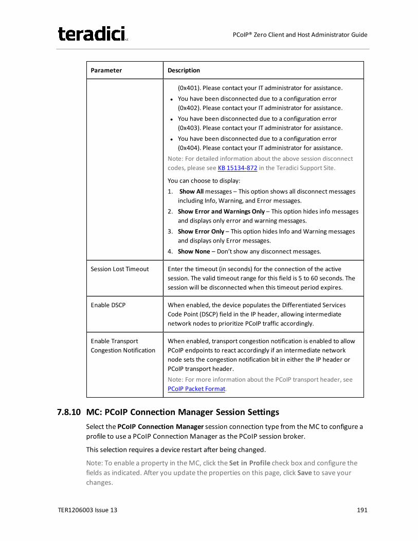
Parameter Description
(0x401). Please contact your IT administrator for assistance.l You have been disconnected due to a configuration error
(0x402). Please contact your IT administrator for assistance.l You have been disconnected due to a configuration error
(0x403). Please contact your IT administrator for assistance.l You have been disconnected due to a configuration error
(0x404). Please contact your IT administrator for assistance.Note: For detailed information about the above session disconnectcodes, please see KB 15134-872 in the Teradici Support Site.
You can choose to display:1. Show Allmessages – This option shows all disconnect messages
including Info, Warning, and Error messages.2. Show Error and Warnings Only – This option hides info messages
and displays only error and warning messages.3. Show Error Only – This option hides Info and Warning messages
and displays only Error messages.4. Show None – Don’t show any disconnect messages.
Session Lost Timeout Enter the timeout (in seconds) for the connection of the activesession. The valid timeout range for this field is 5 to 60 seconds. Thesession will be disconnected when this timeout period expires.
Enable DSCP When enabled, the device populates the Differentiated ServicesCode Point (DSCP) field in the IP header, allowing intermediatenetwork nodes to prioritize PCoIP traffic accordingly.
Enable TransportCongestion Notification
When enabled, transport congestion notification is enabled to allowPCoIP endpoints to react accordingly if an intermediate networknode sets the congestion notification bit in either the IP header orPCoIP transport header.Note: For more information about the PCoIP transport header, seePCoIP Packet Format.
7.8.10 MC: PCoIP Connection Manager Session SettingsSelect the PCoIP Connection Manager session connection type from theMC to configure aprofile to use a PCoIP Connection Manager as the PCoIP session broker.
This selection requires a device restart after being changed.
Note: To enable a property in theMC, click the Set in Profile check box and configure thefields as indicated. After you update the properties on this page, click Save to save yourchanges.
TER1206003 Issue 13 191
PCoIP® Zero Client and Host Administrator Guide
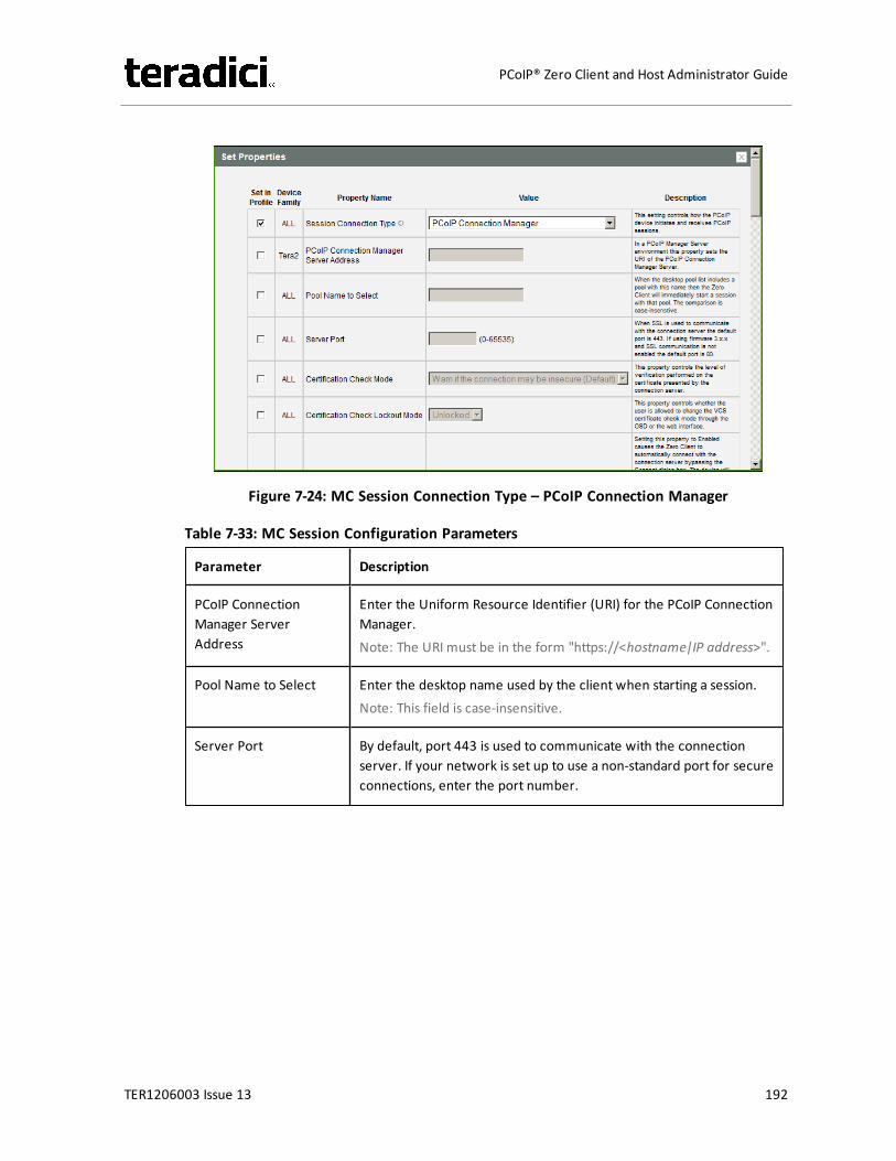
Figure 7-24: MC Session Connection Type – PCoIP Connection Manager
Table 7-33: MC Session Configuration Parameters
Parameter Description
PCoIP ConnectionManager ServerAddress
Enter the Uniform Resource Identifier (URI) for the PCoIP ConnectionManager.Note: The URI must be in the form "https://<hostname|IP address>".
Pool Name to Select Enter the desktop name used by the client when starting a session.Note: This field is case-insensitive.
Server Port By default, port 443 is used to communicate with the connectionserver. If your network is set up to use a non-standard port for secureconnections, enter the port number.
TER1206003 Issue 13 192
PCoIP® Zero Client and Host Administrator Guide
Parameter Description
Certification CheckMode
Select the level of verification performed on the certificatepresented by the connection server:l Warn if the connection may be insecure (Default): Configure the
client to display a warning if an unsigned or expired certificate isencountered, or if the certificate is not self-signed and the zeroclient trust store is empty.
l Reject the unverifiable connection (Secure): Configure the clientto reject the connection if a trusted, valid certificate is notinstalled.
l Allow the unverifiable connection (Not Secure): Configure theclient to allow all connections.
Certification CheckLockout Mode
Select whether to lock or unlock Certification Check Mode:l Unlocked: Select this option to allow users to change the
Certification Check Mode setting using the OSD or AWI.l Locked: Select this option to prevent users from changing the
Certification Check Mode setting.
Auto Connect Mode This field determines the client's auto connect behavior after startup:l Enabled: The client automatically connects with the connection
server after startup and a PCoIP session ends, bypassing the OSDConnect page.
l Disabled: The client does not automatically connect with theconnection server.
l Enabled With Retry On Error: The client will continuouslyattempt to contact the connection server. After a connectionfailure, the client waits before attempting to connect again. Thiswait time increases with each successive failure. The wait intervalis not configurable.Note: Devices running firmware 4.1.1 or lower do not supportRetry On Error behavior and will always perform a single attemptto contact the connection server when this option is selected.
TER1206003 Issue 13 193
PCoIP® Zero Client and Host Administrator Guide
Parameter Description
Connection ServerCache Mode
This field determines whether a connection server is dynamicallyadded to the Server drop-down menu on the OSD Connect pagewhen a user types in a valid server URI, or whether it appears in aread-only list for the user to select.l Last servers used: Select this option if you want a list of cached
servers that a user has typed in to appear in the Server drop-down menu on the OSD Connect page.
l Read-only: Select this option if you want users to select aconnection server from a read-only list.
PCM Server Cache Entry(1 to 25)
Enable the desired number of fields (up to 25) that may appear in thecache on a user's OSD Connect page, and for each one, enter a PCoIPConnection Server URI to which a user is allowed to connect.l If Last servers used is selected in the Connection Server Cache
Mode field, a new connection server is added to the Server drop-down menu whenever the user types in a valid server URI.
l If Read-only is selected, a user can only select a server from aread-only list in the Server drop-down menu.
Self Help Link Mode When enabled, enables the Self Help Link on user authenticationscreens. For a description of this feature, see Enabling the Self HelpLink.
Auto Launch If Only OnePool
When enabled, users are automatically connected to a provisioneddesktop after user credentials are entered.
Enable Login UsernameCaching
When enabled, the username text box automatically populates withthe last username entered.
Use OSD Logo for LoginBanner
When enabled, the OSD logo banner appears at the top of loginscreens in place of the default banner. You can upload an OSD logofrom the OSD Logo Upload page.
Enable Peer LossOverlay
When enabled, the “Network Connection Lost” overlay appears onthe display(s) when a loss of network connectivity is detected.Normal hypervisor scheduling delays can falsely trigger this message.Note: This option is only available for a zero client. Desktopapplications that require the peer loss notification should re-enablethe feature through the OSD, AWI, or MC.
TER1206003 Issue 13 194
PCoIP® Zero Client and Host Administrator Guide
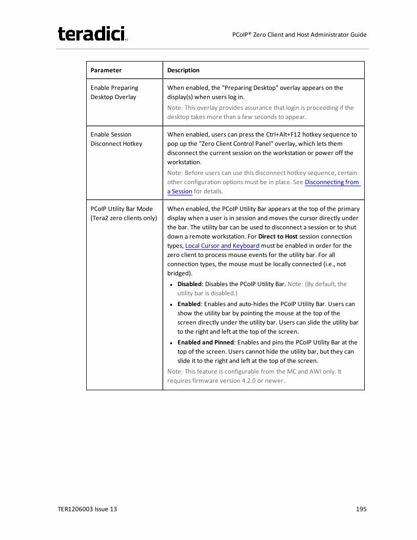
Parameter Description
Enable PreparingDesktop Overlay
When enabled, the "Preparing Desktop" overlay appears on thedisplay(s) when users log in.Note: This overlay provides assurance that login is proceeding if thedesktop takes more than a few seconds to appear.
Enable SessionDisconnect Hotkey
When enabled, users can press the Ctrl+Alt+F12 hotkey sequence topop up the "Zero Client Control Panel" overlay, which lets themdisconnect the current session on the workstation or power off theworkstation.Note: Before users can use this disconnect hotkey sequence, certainother configuration options must be in place. See Disconnecting froma Session for details.
PCoIP Utility Bar Mode(Tera2 zero clients only)
When enabled, the PCoIP Utility Bar appears at the top of the primarydisplay when a user is in session and moves the cursor directly underthe bar. The utility bar can be used to disconnect a session or to shutdown a remote workstation. For Direct to Host session connectiontypes, Local Cursor and Keyboard must be enabled in order for thezero client to process mouse events for the utility bar. For allconnection types, the mouse must be locally connected (i.e., notbridged).l Disabled: Disables the PCoIP Utility Bar. Note: (By default, the
utility bar is disabled.)l Enabled: Enables and auto-hides the PCoIP Utility Bar. Users can
show the utility bar by pointing the mouse at the top of thescreen directly under the utility bar. Users can slide the utility barto the right and left at the top of the screen.
l Enabled and Pinned: Enables and pins the PCoIP Utility Bar at thetop of the screen. Users cannot hide the utility bar, but they canslide it to the right and left at the top of the screen.
Note: This feature is configurable from the MC and AWI only. Itrequires firmware version 4.2.0 or newer.
TER1206003 Issue 13 195
PCoIP® Zero Client and Host Administrator Guide
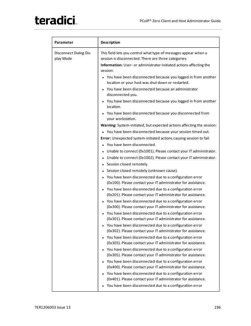
Parameter Description
Disconnect Dialog Dis-play Mode
This field lets you control what type of messages appear when asession is disconnected. There are three categories:Information: User- or administrator-initiated actions affecting thesession:l You have been disconnected because you logged in from another
location or your host was shut down or restarted.l You have been disconnected because an administrator
disconnected you.l You have been disconnected because you logged in from another
location.l You have been disconnected because you disconnected from
your workstation.Warning: System-initiated, but expected actions affecting the session:l You have been disconnected because your session timed out.Error: Unexpected system-initiated actions causing session to fail:l You have been disconnected.l Unable to connect (0x1001). Please contact your IT administrator.l Unable to connect (0x1002). Please contact your IT administrator.l Session closed remotely.l Session closed remotely (unknown cause).l You have been disconnected due to a configuration error
(0x100). Please contact your IT administrator for assistance.l You have been disconnected due to a configuration error
(0x201). Please contact your IT administrator for assistance.l You have been disconnected due to a configuration error
(0x300). Please contact your IT administrator for assistance.l You have been disconnected due to a configuration error
(0x301). Please contact your IT administrator for assistance.l You have been disconnected due to a configuration error
(0x302). Please contact your IT administrator for assistance.l You have been disconnected due to a configuration error
(0x303). Please contact your IT administrator for assistance.l You have been disconnected due to a configuration error
(0x305). Please contact your IT administrator for assistance.l You have been disconnected due to a configuration error
(0x400). Please contact your IT administrator for assistance.l You have been disconnected due to a configuration error
(0x401). Please contact your IT administrator for assistance.l You have been disconnected due to a configuration error
TER1206003 Issue 13 196
PCoIP® Zero Client and Host Administrator Guide
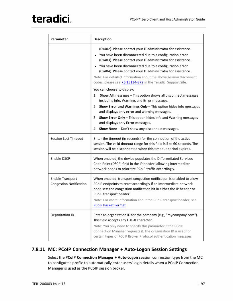
Parameter Description
(0x402). Please contact your IT administrator for assistance.l You have been disconnected due to a configuration error
(0x403). Please contact your IT administrator for assistance.l You have been disconnected due to a configuration error
(0x404). Please contact your IT administrator for assistance.Note: For detailed information about the above session disconnectcodes, please see KB 15134-872 in the Teradici Support Site.
You can choose to display:1. Show Allmessages – This option shows all disconnect messages
including Info, Warning, and Error messages.2. Show Error and Warnings Only – This option hides info messages
and displays only error and warning messages.3. Show Error Only – This option hides Info and Warning messages
and displays only Error messages.4. Show None – Don’t show any disconnect messages.
Session Lost Timeout Enter the timeout (in seconds) for the connection of the activesession. The valid timeout range for this field is 5 to 60 seconds. Thesession will be disconnected when this timeout period expires.
Enable DSCP When enabled, the device populates the Differentiated ServicesCode Point (DSCP) field in the IP header, allowing intermediatenetwork nodes to prioritize PCoIP traffic accordingly.
Enable TransportCongestion Notification
When enabled, transport congestion notification is enabled to allowPCoIP endpoints to react accordingly if an intermediate networknode sets the congestion notification bit in either the IP header orPCoIP transport header.Note: For more information about the PCoIP transport header, seePCoIP Packet Format.
Organization ID Enter an organization ID for the company (e.g., "mycompany.com").This field accepts any UTF-8 character.Note: You only need to specify this parameter if the PCoIPConnection Manager requests it. The organization ID is used forcertain types of PCoIP Broker Protocol authentication messages.
7.8.11 MC: PCoIP Connection Manager + Auto-Logon Session SettingsSelect the PCoIP Connection Manager + Auto-Logon session connection type from theMCto configure a profile to automatically enter users' login details when a PCoIP ConnectionManager is used as the PCoIP session broker.
TER1206003 Issue 13 197
PCoIP® Zero Client and Host Administrator Guide
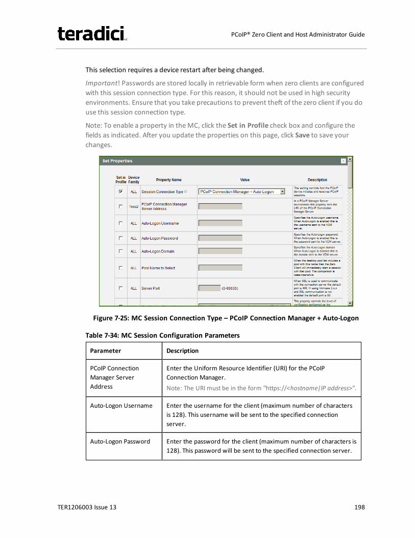
This selection requires a device restart after being changed.
Important! Passwords are stored locally in retrievable form when zero clients are configuredwith this session connection type. For this reason, it should not be used in high securityenvironments. Ensure that you take precautions to prevent theft of the zero client if you douse this session connection type.
Note: To enable a property in theMC, click the Set in Profile check box and configure thefields as indicated. After you update the properties on this page, click Save to save yourchanges.
Figure 7-25: MC Session Connection Type – PCoIP Connection Manager + Auto-Logon
Table 7-34: MC Session Configuration Parameters
Parameter Description
PCoIP ConnectionManager ServerAddress
Enter the Uniform Resource Identifier (URI) for the PCoIPConnection Manager.Note: The URI must be in the form "https://<hostname|IP address>".
Auto-Logon Username Enter the username for the client (maximum number of charactersis 128). This username will be sent to the specified connectionserver.
Auto-Logon Password Enter the password for the client (maximum number of characters is128). This password will be sent to the specified connection server.
TER1206003 Issue 13 198
PCoIP® Zero Client and Host Administrator Guide
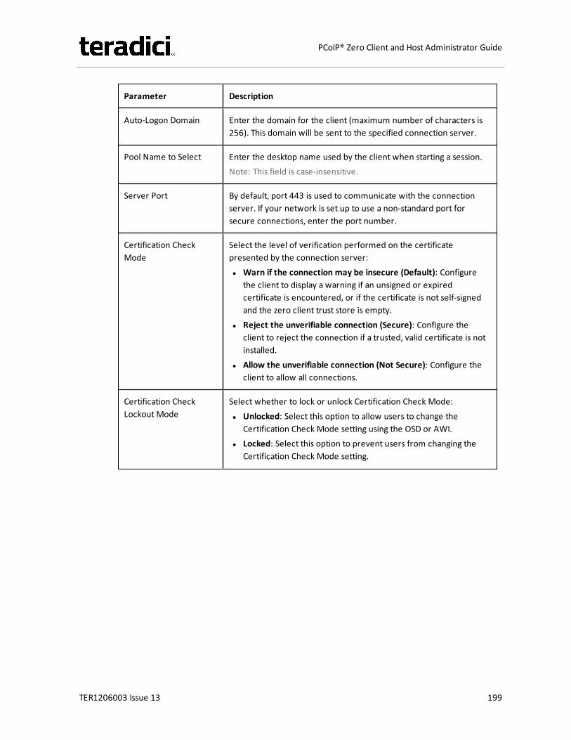
Parameter Description
Auto-Logon Domain Enter the domain for the client (maximum number of characters is256). This domain will be sent to the specified connection server.
Pool Name to Select Enter the desktop name used by the client when starting a session.Note: This field is case-insensitive.
Server Port By default, port 443 is used to communicate with the connectionserver. If your network is set up to use a non-standard port forsecure connections, enter the port number.
Certification CheckMode
Select the level of verification performed on the certificatepresented by the connection server:l Warn if the connection may be insecure (Default): Configure
the client to display a warning if an unsigned or expiredcertificate is encountered, or if the certificate is not self-signedand the zero client trust store is empty.
l Reject the unverifiable connection (Secure): Configure theclient to reject the connection if a trusted, valid certificate is notinstalled.
l Allow the unverifiable connection (Not Secure): Configure theclient to allow all connections.
Certification CheckLockout Mode
Select whether to lock or unlock Certification Check Mode:l Unlocked: Select this option to allow users to change the
Certification Check Mode setting using the OSD or AWI.l Locked: Select this option to prevent users from changing the
Certification Check Mode setting.
TER1206003 Issue 13 199
PCoIP® Zero Client and Host Administrator Guide
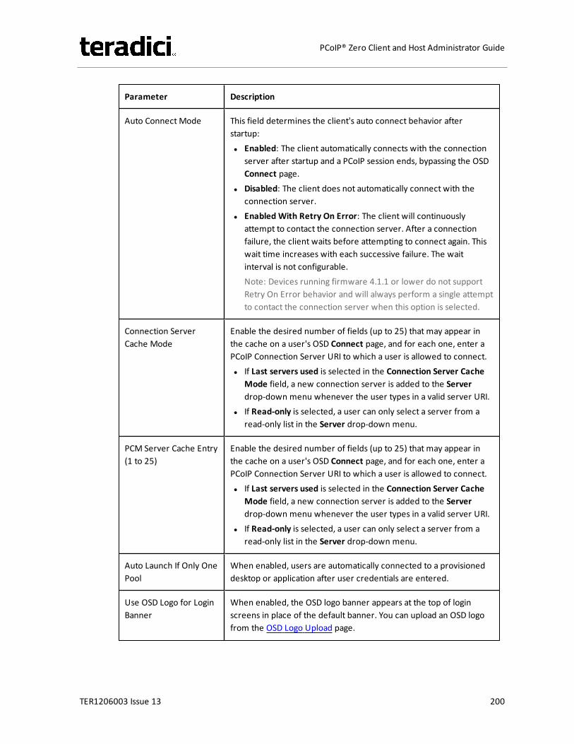
Parameter Description
Auto Connect Mode This field determines the client's auto connect behavior afterstartup:l Enabled: The client automatically connects with the connection
server after startup and a PCoIP session ends, bypassing the OSDConnect page.
l Disabled: The client does not automatically connect with theconnection server.
l Enabled With Retry On Error: The client will continuouslyattempt to contact the connection server. After a connectionfailure, the client waits before attempting to connect again. Thiswait time increases with each successive failure. The waitinterval is not configurable.Note: Devices running firmware 4.1.1 or lower do not supportRetry On Error behavior and will always perform a single attemptto contact the connection server when this option is selected.
Connection ServerCache Mode
Enable the desired number of fields (up to 25) that may appear inthe cache on a user's OSD Connect page, and for each one, enter aPCoIP Connection Server URI to which a user is allowed to connect.l If Last servers used is selected in the Connection Server Cache
Mode field, a new connection server is added to the Serverdrop-down menu whenever the user types in a valid server URI.
l If Read-only is selected, a user can only select a server from aread-only list in the Server drop-down menu.
PCM Server Cache Entry(1 to 25)
Enable the desired number of fields (up to 25) that may appear inthe cache on a user's OSD Connect page, and for each one, enter aPCoIP Connection Server URI to which a user is allowed to connect.l If Last servers used is selected in the Connection Server Cache
Mode field, a new connection server is added to the Serverdrop-down menu whenever the user types in a valid server URI.
l If Read-only is selected, a user can only select a server from aread-only list in the Server drop-down menu.
Auto Launch If Only OnePool
When enabled, users are automatically connected to a provisioneddesktop or application after user credentials are entered.
Use OSD Logo for LoginBanner
When enabled, the OSD logo banner appears at the top of loginscreens in place of the default banner. You can upload an OSD logofrom the OSD Logo Upload page.
TER1206003 Issue 13 200
PCoIP® Zero Client and Host Administrator Guide

Parameter Description
Enable Peer LossOverlay
When enabled, the “Network Connection Lost” overlay appears onthe display(s) when a loss of network connectivity is detected.Normal hypervisor scheduling delays can falsely trigger this message.
Note: This option is only available for a zero client. Desktopapplications that require the peer loss notification should re-enablethe feature through the OSD, AWI, or MC.
Enable PreparingDesktop Overlay
When enabled, the "Preparing Desktop" overlay appears on thedisplay(s) when users log in.Note: This overlay provides assurance that login is proceeding if thedesktop takes more than a few seconds to appear.
Enable SessionDisconnect Hotkey
When enabled, users can press the Ctrl+Alt+F12 hotkey sequence topop up the "Zero Client Control Panel" overlay, which lets themdisconnect the current session on the workstation or power off theworkstation.Note: Before users can use this disconnect hotkey sequence, certainother configuration options must be in place. See Disconnectingfrom a Session for details.
PCoIP Utility Bar Mode(Tera2 zero clients only)
When enabled, the PCoIP Utility Bar appears at the top of theprimary display when a user is in session and moves the cursordirectly under the bar. The utility bar can be used to disconnect asession or to shut down a remote workstation. For Direct to Hostsession connection types, Local Cursor and Keyboard must beenabled in order for the zero client to process mouse events for theutility bar. For all connection types, the mouse must be locallyconnected (i.e., not bridged).l Disabled: Disables the PCoIP Utility Bar. Note: (By default, the
utility bar is disabled.)l Enabled: Enables and auto-hides the PCoIP Utility Bar. Users can
show the utility bar by pointing the mouse at the top of thescreen directly under the utility bar. Users can slide the utility barto the right and left at the top of the screen.
l Enabled and Pinned: Enables and pins the PCoIP Utility Bar at thetop of the screen. Users cannot hide the utility bar, but they canslide it to the right and left at the top of the screen.
Note: This feature is configurable from the MC and AWI only. Itrequires firmware version 4.2.0 or newer.
TER1206003 Issue 13 201
PCoIP® Zero Client and Host Administrator Guide

Parameter Description
Disconnect Dialog Dis-play Mode
This field lets you control what type of messages appear when asession is disconnected. There are three categories:Information: User- or administrator-initiated actions affecting thesession:l You have been disconnected because you logged in from
another location or your host was shut down or restarted.l You have been disconnected because an administrator
disconnected you.l You have been disconnected because you logged in from
another location.l You have been disconnected because you disconnected from
your workstation.Warning: System-initiated, but expected actions affecting thesession:l You have been disconnected because your session timed out.Error: Unexpected system-initiated actions causing session to fail:l You have been disconnected.l Unable to connect (0x1001). Please contact your IT
administrator.l Unable to connect (0x1002). Please contact your IT
administrator.l Session closed remotely.l Session closed remotely (unknown cause).l You have been disconnected due to a configuration error
(0x100). Please contact your IT administrator for assistance.l You have been disconnected due to a configuration error
(0x201). Please contact your IT administrator for assistance.l You have been disconnected due to a configuration error
(0x300). Please contact your IT administrator for assistance.l You have been disconnected due to a configuration error
(0x301). Please contact your IT administrator for assistance.l You have been disconnected due to a configuration error
(0x302). Please contact your IT administrator for assistance.l You have been disconnected due to a configuration error
(0x303). Please contact your IT administrator for assistance.l You have been disconnected due to a configuration error
(0x305). Please contact your IT administrator for assistance.l You have been disconnected due to a configuration error
(0x400). Please contact your IT administrator for assistance.l You have been disconnected due to a configuration error
TER1206003 Issue 13 202
PCoIP® Zero Client and Host Administrator Guide
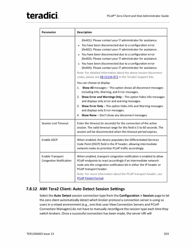
Parameter Description
(0x401). Please contact your IT administrator for assistance.l You have been disconnected due to a configuration error
(0x402). Please contact your IT administrator for assistance.l You have been disconnected due to a configuration error
(0x403). Please contact your IT administrator for assistance.l You have been disconnected due to a configuration error
(0x404). Please contact your IT administrator for assistance.Note: For detailed information about the above session disconnectcodes, please see KB 15134-872 in the Teradici Support Site.
You can choose to display:1. Show Allmessages – This option shows all disconnect messages
including Info, Warning, and Error messages.2. Show Error and Warnings Only – This option hides info messages
and displays only error and warning messages.3. Show Error Only – This option hides Info and Warning messages
and displays only Error messages.4. Show None – Don’t show any disconnect messages.
Session Lost Timeout Enter the timeout (in seconds) for the connection of the activesession. The valid timeout range for this field is 5 to 60 seconds. Thesession will be disconnected when this timeout period expires.
Enable DSCP When enabled, the device populates the Differentiated ServicesCode Point (DSCP) field in the IP header, allowing intermediatenetwork nodes to prioritize PCoIP traffic accordingly.
Enable TransportCongestion Notification
When enabled, transport congestion notification is enabled to allowPCoIP endpoints to react accordingly if an intermediate networknode sets the congestion notification bit in either the IP header orPCoIP transport header.Note: For more information about the PCoIP transport header, seePCoIP Packet Format.
7.8.12 AWI Tera2 Client: Auto Detect Session SettingsSelect the Auto Detect session connection type from the Configuration > Session page to letthe zero client automatically detect which broker protocol a connection server is using sousers in a mixed environment (e.g., one that uses View Connection Servers and PCoIPConnection Managers) do not have to manually reconfigure the session type each time theyswitch brokers. Once a successful connection has been made, the server URI will
TER1206003 Issue 13 203
PCoIP® Zero Client and Host Administrator Guide
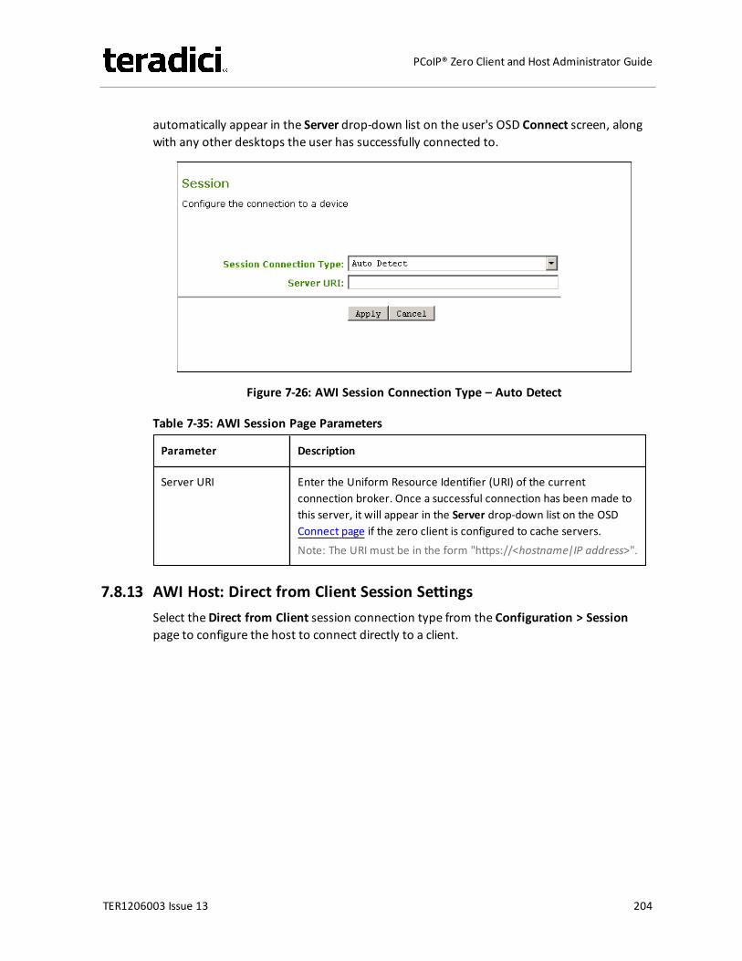
automatically appear in the Server drop-down list on the user's OSD Connect screen, alongwith any other desktops the user has successfully connected to.
Figure 7-26: AWI Session Connection Type – Auto Detect
Table 7-35: AWI Session Page Parameters
Parameter Description
Server URI Enter the Uniform Resource Identifier (URI) of the currentconnection broker. Once a successful connection has been made tothis server, it will appear in the Server drop-down list on the OSDConnect page if the zero client is configured to cache servers.Note: The URI must be in the form "https://<hostname|IP address>".
7.8.13 AWI Host: Direct from Client Session SettingsSelect theDirect from Client session connection type from the Configuration > Sessionpage to configure the host to connect directly to a client.
TER1206003 Issue 13 204
PCoIP® Zero Client and Host Administrator Guide
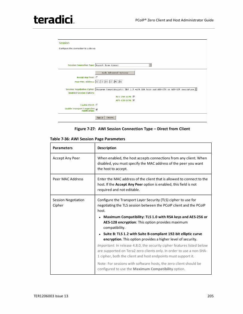
Figure 7-27: AWI Session Connection Type – Direct from Client
Table 7-36: AWI Session Page Parameters
Parameters Description
Accept Any Peer When enabled, the host accepts connections from any client. Whendisabled, you must specify the MAC address of the peer you wantthe host to accept.
Peer MAC Address Enter the MAC address of the client that is allowed to connect to thehost. If the Accept Any Peer option is enabled, this field is notrequired and not editable.
Session NegotiationCipher
Configure the Transport Layer Security (TLS) cipher to use fornegotiating the TLS session between the PCoIP client and the PCoIPhost.l Maximum Compatibility: TLS 1.0 with RSA keys and AES-256 or
AES-128 encryption: This option provides maximumcompatibility.
l Suite B: TLS 1.2 with Suite B-compliant 192-bit elliptic curveencryption. This option provides a higher level of security.
Important: In release 4.8.0, the security cipher features listed beloware supported on Tera2 zero clients only. In order to use a non-SHA-1 cipher, both the client and host endpoints must support it.
Note: For sessions with software hosts, the zero client should beconfigured to use the Maximum Compatibility option.
TER1206003 Issue 13 205
PCoIP® Zero Client and Host Administrator Guide

Parameters Description
Enabled Session Ciphers Enable or disable an encryption mode for the device. By default, allencryption modes that pertain to a device are enabled.l AES-128-GCM (Tera1 and Tera2): An encryption method
implemented in first-generation Tera1 and second-generationTera2 processors. This method offers the best performancebetween hardware endpoints for Tera1 devices. AES-128-GCMalso may offer improved performance for Tera2 clients whenconnecting to VMware 4 or newer if there is more than about 7Mbps available on the network.
l AES-256-GCM (Tera2 only): A more secure encryption methodimplemented in second-generation Tera2 processors that offersthe best performance between hardware endpoints. Whenconnecting to VMware 4 or newer, AES-128-GCM isrecommended.
l Salsa20-256-Round12 (Tera1 only): A lighter encryption methodimplemented in firmware that may offer improved performancefor Tera1 clients when connecting to VMware View 4 or newer ifthere is more than about 7 Mbps available on the network.
Note: For more information about connecting to VMware Horizonvirtual desktops, see “Using PCoIP® Zero Clients with VMware ViewUser Guide” (TER0904005) in the Teradici Support DocumentationCenter.
Note: The enabled encryption mode must match between the hostand client for a session to be established. If more than one mode isenabled, the firmware selects the following:
l Host to Tera1 or Tera2 clients: AES-128-GCM or AES-256-GCMfor the PCoIP session.
l VMware View 4.5 and later to Tera1 client: SALSA20-256-Round12 for the PCoIP session.
l VMware View 4.5 and later to Tera2 client: AES-128-GCM for thePCoIP session.
Enable DSCP When enabled, the device populates the Differentiated ServicesCode Point (DSCP) field in the IP header, allowing intermediatenetwork nodes to prioritize PCoIP traffic accordingly.
Enable TransportCongestion Notification
When enabled, transport congestion notification is enabled to allowPCoIP endpoints to react accordingly if an intermediate networknode sets the congestion notification bit in either the IP header orPCoIP transport header.Note: For more information about the PCoIP transport header, seePCoIP Packet Format.
TER1206003 Issue 13 206
PCoIP® Zero Client and Host Administrator Guide
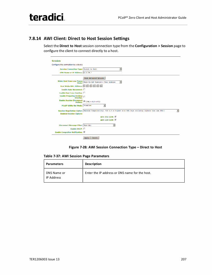
7.8.14 AWI Client: Direct to Host Session SettingsSelect theDirect to Host session connection type from the Configuration > Session page toconfigure the client to connect directly to a host.
Figure 7-28: AWI Session Connection Type – Direct to Host
Table 7-37: AWI Session Page Parameters
Parameters Description
DNS Name orIP Address
Enter the IP address or DNS name for the host.
TER1206003 Issue 13 207
PCoIP® Zero Client and Host Administrator Guide

Parameters Description
Wake Host from LowPower State
Select whether to use the remote workstation card's MAC and IPaddress or a custom MAC and IP address when configuring theWake-On-LAN feature on a client. This feature wakes up the hostwhen the user presses the client's host PC button or clicks theConnect button on the Connect window.l Wake-On-LAN Enabled + Peer Address: After you have
successfully connected to the remote workstation card, both thecard's MAC address and IP address are automatically populated inthe Host Wake MAC Address and Host Wake IP Address fields.
l Wake-On-LAN Enabled + Custom Address: When selected,allows you to manually enter the MAC address and IP address ofthe device you want to wake up.Note: If the host software is installed in the host PC and the Usehost PC NIC for Wake-on-LAN setting is enabled in the Features> Power Management section of the host software GUI, theMAC address and IP address of the host PC's network interfacecard (NIC) will automatically be populated in the Host Wake MACAddress and Host Wake IP Address fields.
Note:
l The hardware host must be able to support waking from lowpower state (off/hibernate/sleep) when it receives a wake-on-LAN packet.
l For Tera2 clients, you can disable the Wake-On-LAN feature fromthe AWI Power page or the MC Power Permissions. page.
HostWake MACAddress
Enter the host's MAC address to complete the host wake upconfiguration whenWake-On-LAN Enabled + Peer Address orWake-On-LAN Enabled + Custom Address is selected. The client willsend a "magic packet" to this MAC address to wake the hostcomputer from a low power state.
HostWake IP Address Enter the host's IP address to complete the host wake upconfiguration whenWake-On-LAN Enabled + Custom Address isselected. The client will send a "magic packet" to this IP address towake the host computer from a low power state.
Enable Auto-Reconnect When enabled, lets the client automatically reconnect with the lastconnected host when a session is lost.
TER1206003 Issue 13 208
PCoIP® Zero Client and Host Administrator Guide

Parameters Description
Enable Peer LossOverlay
When enabled, the “Network Connection Lost” overlay appears onthe display(s) when a loss of network connectivity is detected.Normal hypervisor scheduling delays can falsely trigger this message.
Note: This option is only available for a zero client. Desktopapplications that require the peer loss notification should re-enablethe feature through the OSD, AWI, or MC.
Enable PreparingDesktop Overlay
When enabled, the "Preparing Desktop" overlay appears on thedisplay(s) when users log in.Note: This overlay provides assurance that login is proceeding if thedesktop takes more than a few seconds to appear.
Enable SessionDisconnect Hotkey
When enabled, users can press the Ctrl+Alt+F12 hotkey sequence topop up the "Zero Client Control Panel" overlay, which lets themdisconnect the current session on the workstation or power off theworkstation.Note: Before users can use this disconnect hotkey sequence, certainother configuration options must be in place. See Disconnectingfrom a Session for details.
PCoIP Utility Bar Mode(Tera2 zero clients only)
When enabled, the PCoIP Utility Bar appears at the top of theprimary display when a user is in session and moves the cursordirectly under the bar. The utility bar can be used to disconnect asession or to shut down a remote workstation. For Direct to Hostsession connection types, Local Cursor and Keyboard must beenabled in order for the zero client to process mouse events for theutility bar. For all connection types, the mouse must be locallyconnected (i.e., not bridged).l Disabled: Disables the PCoIP Utility Bar. Note: (By default, the
utility bar is disabled.)l Enabled: Enables and auto-hides the PCoIP Utility Bar. Users can
show the utility bar by pointing the mouse at the top of thescreen directly under the utility bar. Users can slide the utility barto the right and left at the top of the screen.
l Enabled and Pinned: Enables and pins the PCoIP Utility Bar at thetop of the screen. Users cannot hide the utility bar, but they canslide it to the right and left at the top of the screen.
Note: This feature is configurable from the MC and AWI only. Itrequires firmware version 4.2.0 or newer.
TER1206003 Issue 13 209
PCoIP® Zero Client and Host Administrator Guide

Parameters Description
Session NegotiationCipher
Important: In release 4.8.0, the security cipher features listed beloware supported on Tera2 zero clients only. In order to use a non-SHA-1 cipher, both the client and host endpoints must support it.
Note: For sessions with software hosts, the zero client should beconfigured to use the Maximum Compatibility option.
For Tera2 zero clients:Configure the Transport Layer Security (TLS) cipher to use fornegotiating the TLS session between the PCoIP client and the PCoIPhost.l Maximum Compatibility: TLS 1.0 or higher with RSA keys
including ciphers that use SHA-1: This option provides maximumcompatibility.
l Suite B: TLS 1.2 with Suite B-compliant 192-bit elliptic curveencryption. This option provides a higher level of security.
l Disable SHA-1: TLS 1.2 with RSA keys and strong ciphers usingonly SHA-256 or SHA-384: When selected, only devices runningfirmware 4.8.0 or greater are affected.Note: Currently this option can only be used with AmazonWorkSpaces hosts.
For Tera1 zero clients:Configure the Transport Layer Security (TLS) cipher to use fornegotiating the TLS session between the PCoIP client and the PCoIPhost.l Maximum Compatibility: TLS 1.0 with RSA keys and AES-256 or
AES-128 encryption: This option provides maximumcompatibility.
l Suite B: TLS 1.2 with Suite B-compliant 192-bit elliptic curveencryption. This option provides a higher level of security.
TER1206003 Issue 13 210
PCoIP® Zero Client and Host Administrator Guide

Parameters Description
Enabled Session Ciphers Enable or disable an encryption mode for the device. By default, allencryption modes that pertain to a device are enabled.l AES-128-GCM (Tera1 and Tera2): An encryption method
implemented in first-generation Tera1 and second-generationTera2 processors. This method offers the best performancebetween hardware endpoints for Tera1 devices. AES-128-GCMalso may offer improved performance for Tera2 clients whenconnecting to VMware 4 or newer if there is more than about 7Mbps available on the network.
l AES-256-GCM (Tera2 only): A more secure encryption methodimplemented in second-generation Tera2 processors that offersthe best performance between hardware endpoints. Whenconnecting to VMware 4 or newer, AES-128-GCM isrecommended.
l Salsa20-256-Round12 (Tera1 only): A lighter encryption methodimplemented in firmware that may offer improved performancefor Tera1 clients when connecting to VMware View 4 or newer ifthere is more than about 7 Mbps available on the network.
Note: For more information about connecting to VMware Horizonvirtual desktops, see “Using PCoIP® Zero Clients with VMware ViewUser Guide” (TER0904005) in the Teradici Support DocumentationCenter.
Note: The enabled encryption mode must match between the hostand client for a session to be established. If more than one mode isenabled, the firmware selects the following:
l Host to Tera1 or Tera2 clients: AES-128-GCM or AES-256-GCMfor the PCoIP session.
l VMware View 4.5 and later to Tera1 client: SALSA20-256-Round12 for the PCoIP session.
l VMware View 4.5 and later to Tera2 client: AES-128-GCM for thePCoIP session.
TER1206003 Issue 13 211
PCoIP® Zero Client and Host Administrator Guide

Parameters Description
Disconnect MessageFilter
This field lets you control what type of messages appear when asession is disconnected. There are three categories:Information: User- or administrator-initiated actions affecting thesession:l You have been disconnected because you logged in from
another location or your host was shut down or restarted.l You have been disconnected because an administrator
disconnected you.l You have been disconnected because you logged in from
another location.l You have been disconnected because you disconnected from
your workstation.Warning: System-initiated, but expected actions affecting thesession:l You have been disconnected because your session timed out.Error: Unexpected system-initiated actions causing session to fail:l You have been disconnected.l Unable to connect (0x1001). Please contact your IT
administrator.l Unable to connect (0x1002). Please contact your IT
administrator.l Session closed remotely.l Session closed remotely (unknown cause).l You have been disconnected due to a configuration error
(0x100). Please contact your IT administrator for assistance.l You have been disconnected due to a configuration error
(0x201). Please contact your IT administrator for assistance.l You have been disconnected due to a configuration error
(0x300). Please contact your IT administrator for assistance.l You have been disconnected due to a configuration error
(0x301). Please contact your IT administrator for assistance.l You have been disconnected due to a configuration error
(0x302). Please contact your IT administrator for assistance.l You have been disconnected due to a configuration error
(0x303). Please contact your IT administrator for assistance.l You have been disconnected due to a configuration error
(0x305). Please contact your IT administrator for assistance.l You have been disconnected due to a configuration error
(0x400). Please contact your IT administrator for assistance.l You have been disconnected due to a configuration error
TER1206003 Issue 13 212
PCoIP® Zero Client and Host Administrator Guide
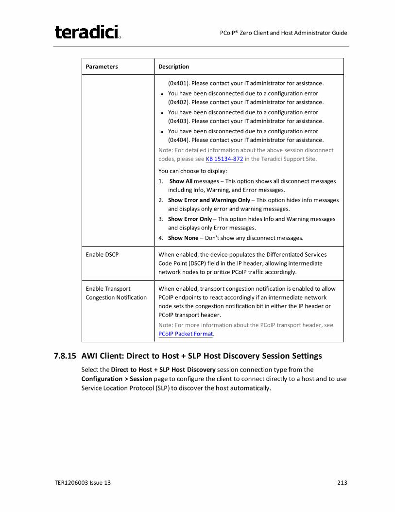
Parameters Description
(0x401). Please contact your IT administrator for assistance.l You have been disconnected due to a configuration error
(0x402). Please contact your IT administrator for assistance.l You have been disconnected due to a configuration error
(0x403). Please contact your IT administrator for assistance.l You have been disconnected due to a configuration error
(0x404). Please contact your IT administrator for assistance.Note: For detailed information about the above session disconnectcodes, please see KB 15134-872 in the Teradici Support Site.
You can choose to display:1. Show Allmessages – This option shows all disconnect messages
including Info, Warning, and Error messages.2. Show Error and Warnings Only – This option hides info messages
and displays only error and warning messages.3. Show Error Only – This option hides Info and Warning messages
and displays only Error messages.4. Show None – Don’t show any disconnect messages.
Enable DSCP When enabled, the device populates the Differentiated ServicesCode Point (DSCP) field in the IP header, allowing intermediatenetwork nodes to prioritize PCoIP traffic accordingly.
Enable TransportCongestion Notification
When enabled, transport congestion notification is enabled to allowPCoIP endpoints to react accordingly if an intermediate networknode sets the congestion notification bit in either the IP header orPCoIP transport header.Note: For more information about the PCoIP transport header, seePCoIP Packet Format.
7.8.15 AWI Client: Direct to Host + SLP Host Discovery Session SettingsSelect theDirect to Host + SLP Host Discovery session connection type from theConfiguration > Session page to configure the client to connect directly to a host and to useService Location Protocol (SLP) to discover the host automatically.
TER1206003 Issue 13 213
PCoIP® Zero Client and Host Administrator Guide
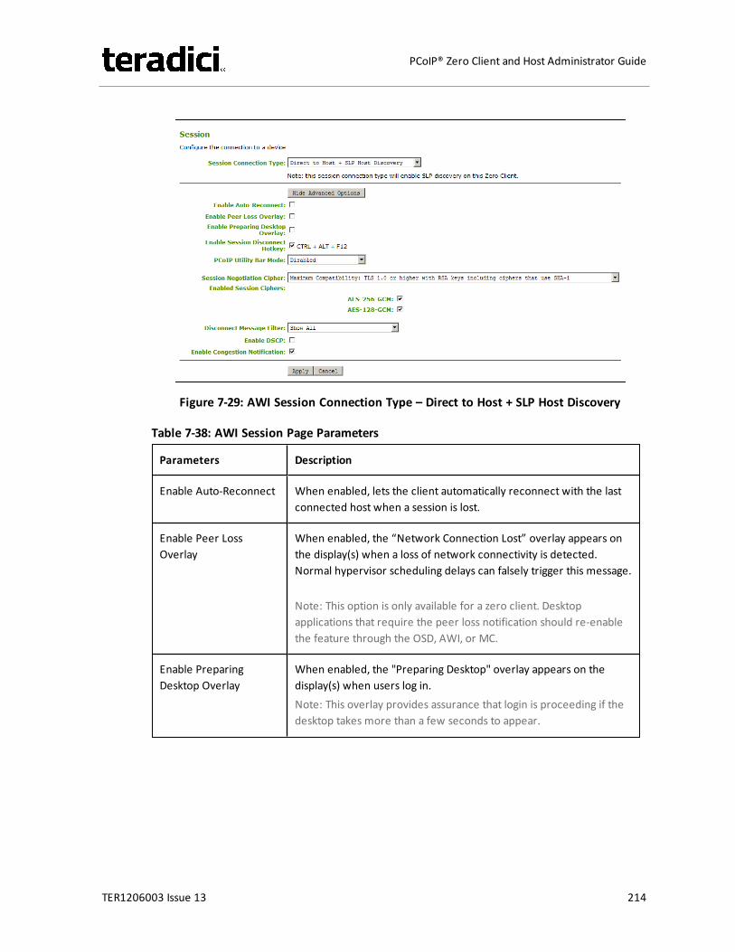
Figure 7-29: AWI Session Connection Type – Direct to Host + SLP Host Discovery
Table 7-38: AWI Session Page Parameters
Parameters Description
Enable Auto-Reconnect When enabled, lets the client automatically reconnect with the lastconnected host when a session is lost.
Enable Peer LossOverlay
When enabled, the “Network Connection Lost” overlay appears onthe display(s) when a loss of network connectivity is detected.Normal hypervisor scheduling delays can falsely trigger this message.
Note: This option is only available for a zero client. Desktopapplications that require the peer loss notification should re-enablethe feature through the OSD, AWI, or MC.
Enable PreparingDesktop Overlay
When enabled, the "Preparing Desktop" overlay appears on thedisplay(s) when users log in.Note: This overlay provides assurance that login is proceeding if thedesktop takes more than a few seconds to appear.
TER1206003 Issue 13 214
PCoIP® Zero Client and Host Administrator Guide
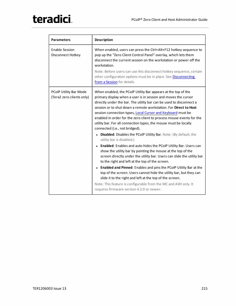
Parameters Description
Enable SessionDisconnect Hotkey
When enabled, users can press the Ctrl+Alt+F12 hotkey sequence topop up the "Zero Client Control Panel" overlay, which lets themdisconnect the current session on the workstation or power off theworkstation.Note: Before users can use this disconnect hotkey sequence, certainother configuration options must be in place. See Disconnectingfrom a Session for details.
PCoIP Utility Bar Mode(Tera2 zero clients only)
When enabled, the PCoIP Utility Bar appears at the top of theprimary display when a user is in session and moves the cursordirectly under the bar. The utility bar can be used to disconnect asession or to shut down a remote workstation. For Direct to Hostsession connection types, Local Cursor and Keyboard must beenabled in order for the zero client to process mouse events for theutility bar. For all connection types, the mouse must be locallyconnected (i.e., not bridged).l Disabled: Disables the PCoIP Utility Bar. Note: (By default, the
utility bar is disabled.)l Enabled: Enables and auto-hides the PCoIP Utility Bar. Users can
show the utility bar by pointing the mouse at the top of thescreen directly under the utility bar. Users can slide the utility barto the right and left at the top of the screen.
l Enabled and Pinned: Enables and pins the PCoIP Utility Bar at thetop of the screen. Users cannot hide the utility bar, but they canslide it to the right and left at the top of the screen.
Note: This feature is configurable from the MC and AWI only. Itrequires firmware version 4.2.0 or newer.
TER1206003 Issue 13 215
PCoIP® Zero Client and Host Administrator Guide

Parameters Description
Session NegotiationCipher
Important: In release 4.8.0, the security cipher features listed beloware supported on Tera2 zero clients only. In order to use a non-SHA-1 cipher, both the client and host endpoints must support it.
Note: For sessions with software hosts, the zero client should beconfigured to use the Maximum Compatibility option.
For Tera2 zero clients:Configure the Transport Layer Security (TLS) cipher to use fornegotiating the TLS session between the PCoIP client and the PCoIPhost.l Maximum Compatibility: TLS 1.0 or higher with RSA keys
including ciphers that use SHA-1: This option provides maximumcompatibility.
l Suite B: TLS 1.2 with Suite B-compliant 192-bit elliptic curveencryption. This option provides a higher level of security.
l Disable SHA-1: TLS 1.2 with RSA keys and strong ciphers usingonly SHA-256 or SHA-384: When selected, only devices runningfirmware 4.8.0 or greater are affected.Note: Currently this option can only be used with AmazonWorkSpaces hosts.
For Tera1 zero clients:Configure the Transport Layer Security (TLS) cipher to use fornegotiating the TLS session between the PCoIP client and the PCoIPhost.l Maximum Compatibility: TLS 1.0 with RSA keys and AES-256 or
AES-128 encryption: This option provides maximumcompatibility.
l Suite B: TLS 1.2 with Suite B-compliant 192-bit elliptic curveencryption. This option provides a higher level of security.
TER1206003 Issue 13 216
PCoIP® Zero Client and Host Administrator Guide

Parameters Description
Enabled Session Ciphers Enable or disable an encryption mode for the device. By default, allencryption modes that pertain to a device are enabled.l AES-128-GCM (Tera1 and Tera2): An encryption method
implemented in first-generation Tera1 and second-generationTera2 processors. This method offers the best performancebetween hardware endpoints for Tera1 devices. AES-128-GCMalso may offer improved performance for Tera2 clients whenconnecting to VMware 4 or newer if there is more than about 7Mbps available on the network.
l AES-256-GCM (Tera2 only): A more secure encryption methodimplemented in second-generation Tera2 processors that offersthe best performance between hardware endpoints. Whenconnecting to VMware 4 or newer, AES-128-GCM isrecommended.
l Salsa20-256-Round12 (Tera1 only): A lighter encryption methodimplemented in firmware that may offer improved performancefor Tera1 clients when connecting to VMware View 4 or newer ifthere is more than about 7 Mbps available on the network.
Note: For more information about connecting to VMware Horizonvirtual desktops, see “Using PCoIP® Zero Clients with VMware ViewUser Guide” (TER0904005) in the Teradici Support DocumentationCenter.
Note: The enabled encryption mode must match between the hostand client for a session to be established. If more than one mode isenabled, the firmware selects the following:
l Host to Tera1 or Tera2 clients: AES-128-GCM or AES-256-GCMfor the PCoIP session.
l VMware View 4.5 and later to Tera1 client: SALSA20-256-Round12 for the PCoIP session.
l VMware View 4.5 and later to Tera2 client: AES-128-GCM for thePCoIP session.
TER1206003 Issue 13 217
PCoIP® Zero Client and Host Administrator Guide

Parameters Description
Disconnect MessageFilter
This field lets you control what type of messages appear when asession is disconnected. There are three categories:Information: User- or administrator-initiated actions affecting thesession:l You have been disconnected because you logged in from
another location or your host was shut down or restarted.l You have been disconnected because an administrator
disconnected you.l You have been disconnected because you logged in from
another location.l You have been disconnected because you disconnected from
your workstation.Warning: System-initiated, but expected actions affecting thesession:l You have been disconnected because your session timed out.Error: Unexpected system-initiated actions causing session to fail:l You have been disconnected.l Unable to connect (0x1001). Please contact your IT
administrator.l Unable to connect (0x1002). Please contact your IT
administrator.l Session closed remotely.l Session closed remotely (unknown cause).l You have been disconnected due to a configuration error
(0x100). Please contact your IT administrator for assistance.l You have been disconnected due to a configuration error
(0x201). Please contact your IT administrator for assistance.l You have been disconnected due to a configuration error
(0x300). Please contact your IT administrator for assistance.l You have been disconnected due to a configuration error
(0x301). Please contact your IT administrator for assistance.l You have been disconnected due to a configuration error
(0x302). Please contact your IT administrator for assistance.l You have been disconnected due to a configuration error
(0x303). Please contact your IT administrator for assistance.l You have been disconnected due to a configuration error
(0x305). Please contact your IT administrator for assistance.l You have been disconnected due to a configuration error
(0x400). Please contact your IT administrator for assistance.l You have been disconnected due to a configuration error
TER1206003 Issue 13 218
PCoIP® Zero Client and Host Administrator Guide
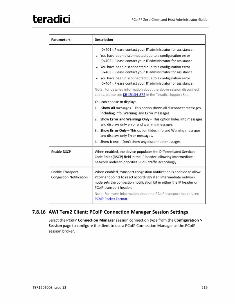
Parameters Description
(0x401). Please contact your IT administrator for assistance.l You have been disconnected due to a configuration error
(0x402). Please contact your IT administrator for assistance.l You have been disconnected due to a configuration error
(0x403). Please contact your IT administrator for assistance.l You have been disconnected due to a configuration error
(0x404). Please contact your IT administrator for assistance.Note: For detailed information about the above session disconnectcodes, please see KB 15134-872 in the Teradici Support Site.
You can choose to display:1. Show Allmessages – This option shows all disconnect messages
including Info, Warning, and Error messages.2. Show Error and Warnings Only – This option hides info messages
and displays only error and warning messages.3. Show Error Only – This option hides Info and Warning messages
and displays only Error messages.4. Show None – Don’t show any disconnect messages.
Enable DSCP When enabled, the device populates the Differentiated ServicesCode Point (DSCP) field in the IP header, allowing intermediatenetwork nodes to prioritize PCoIP traffic accordingly.
Enable TransportCongestion Notification
When enabled, transport congestion notification is enabled to allowPCoIP endpoints to react accordingly if an intermediate networknode sets the congestion notification bit in either the IP header orPCoIP transport header.Note: For more information about the PCoIP transport header, seePCoIP Packet Format.
7.8.16 AWI Tera2 Client: PCoIP Connection Manager Session SettingsSelect the PCoIP Connection Manager session connection type from the Configuration >Session page to configure the client to use a PCoIP Connection Manager as the PCoIPsession broker.
TER1206003 Issue 13 219
PCoIP® Zero Client and Host Administrator Guide
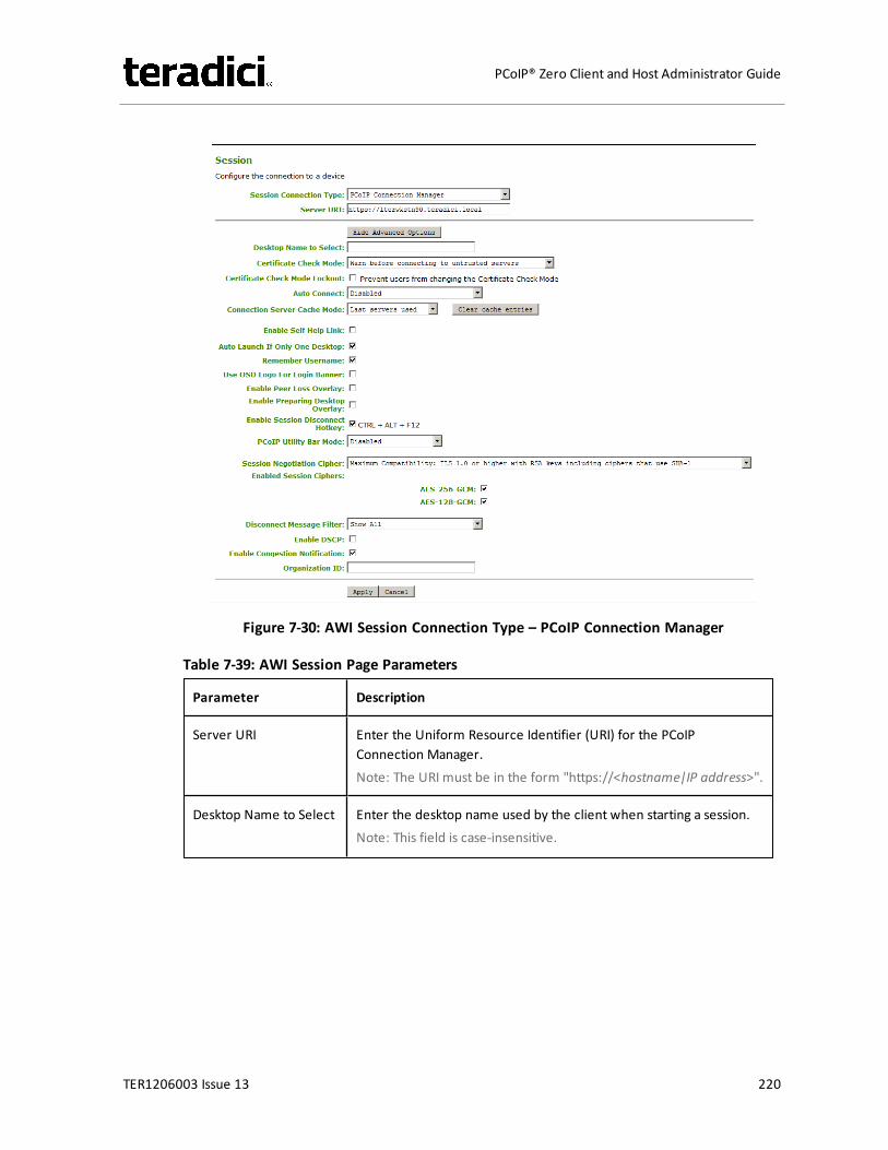
Figure 7-30: AWI Session Connection Type – PCoIP Connection Manager
Table 7-39: AWI Session Page Parameters
Parameter Description
Server URI Enter the Uniform Resource Identifier (URI) for the PCoIPConnection Manager.Note: The URI must be in the form "https://<hostname|IP address>".
Desktop Name to Select Enter the desktop name used by the client when starting a session.Note: This field is case-insensitive.
TER1206003 Issue 13 220
PCoIP® Zero Client and Host Administrator Guide
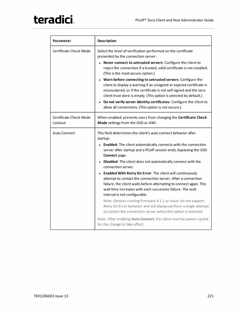
Parameter Description
Certificate Check Mode Select the level of verification performed on the certificatepresented by the connection server:l Never connect to untrusted servers: Configure the client to
reject the connection if a trusted, valid certificate is not installed.(This is the most secure option.)
l Warn before connecting to untrusted servers: Configure theclient to display a warning if an unsigned or expired certificate isencountered, or if the certificate is not self-signed and the zeroclient trust store is empty. (This option is selected by default.)
l Do not verify server identity certificates: Configure the client toallow all connections. (This option is not secure.)
Certificate Check ModeLockout
When enabled, prevents users from changing the Certificate CheckMode settings from the OSD or AWI.
Auto Connect This field determines the client's auto connect behavior afterstartup:l Enabled: The client automatically connects with the connection
server after startup and a PCoIP session ends, bypassing the OSDConnect page.
l Disabled: The client does not automatically connect with theconnection server.
l Enabled With Retry On Error: The client will continuouslyattempt to contact the connection server. After a connectionfailure, the client waits before attempting to connect again. Thiswait time increases with each successive failure. The waitinterval is not configurable.Note: Devices running firmware 4.1.1 or lower do not supportRetry On Error behavior and will always perform a single attemptto contact the connection server when this option is selected.
Note: After enabling Auto Connect, the client must be power-cycledfor the change to take effect.
TER1206003 Issue 13 221
PCoIP® Zero Client and Host Administrator Guide
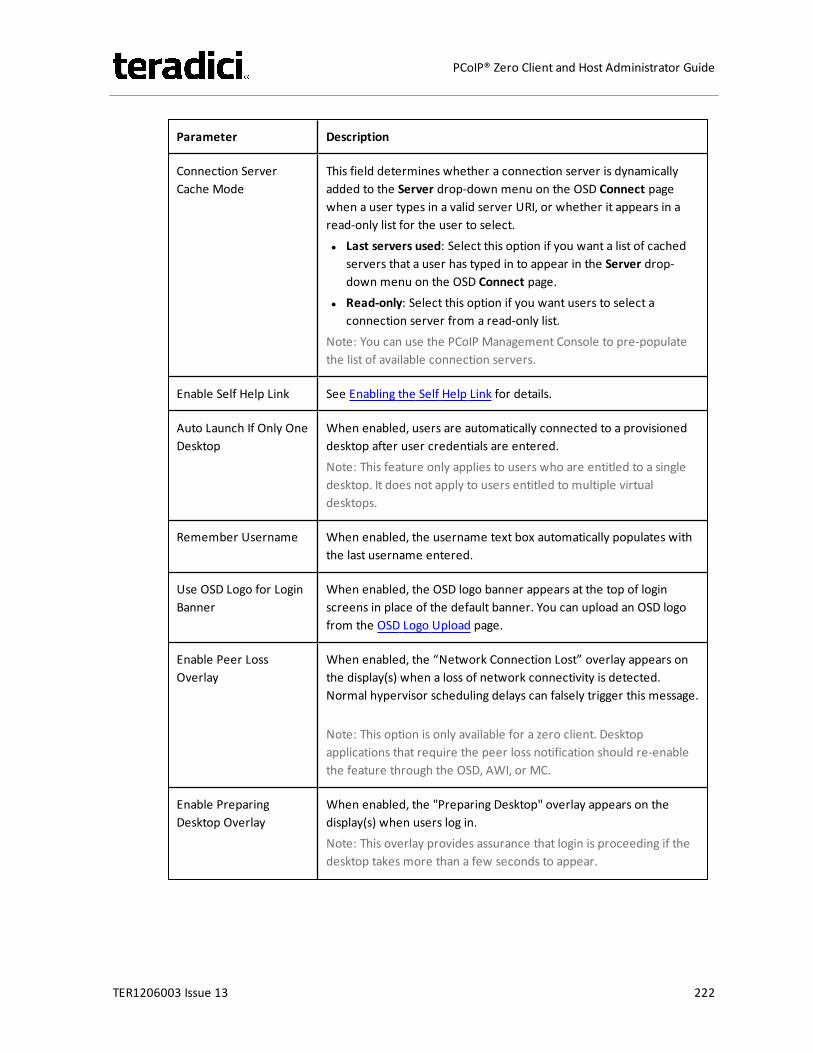
Parameter Description
Connection ServerCache Mode
This field determines whether a connection server is dynamicallyadded to the Server drop-down menu on the OSD Connect pagewhen a user types in a valid server URI, or whether it appears in aread-only list for the user to select.l Last servers used: Select this option if you want a list of cached
servers that a user has typed in to appear in the Server drop-down menu on the OSD Connect page.
l Read-only: Select this option if you want users to select aconnection server from a read-only list.
Note: You can use the PCoIP Management Console to pre-populatethe list of available connection servers.
Enable Self Help Link See Enabling the Self Help Link for details.
Auto Launch If Only OneDesktop
When enabled, users are automatically connected to a provisioneddesktop after user credentials are entered.Note: This feature only applies to users who are entitled to a singledesktop. It does not apply to users entitled to multiple virtualdesktops.
Remember Username When enabled, the username text box automatically populates withthe last username entered.
Use OSD Logo for LoginBanner
When enabled, the OSD logo banner appears at the top of loginscreens in place of the default banner. You can upload an OSD logofrom the OSD Logo Upload page.
Enable Peer LossOverlay
When enabled, the “Network Connection Lost” overlay appears onthe display(s) when a loss of network connectivity is detected.Normal hypervisor scheduling delays can falsely trigger this message.
Note: This option is only available for a zero client. Desktopapplications that require the peer loss notification should re-enablethe feature through the OSD, AWI, or MC.
Enable PreparingDesktop Overlay
When enabled, the "Preparing Desktop" overlay appears on thedisplay(s) when users log in.Note: This overlay provides assurance that login is proceeding if thedesktop takes more than a few seconds to appear.
TER1206003 Issue 13 222
PCoIP® Zero Client and Host Administrator Guide

Parameter Description
Enable SessionDisconnect Hotkey
When enabled, users can press the Ctrl+Alt+F12 hotkey sequence topop up the "Zero Client Control Panel" overlay, which lets themdisconnect the current session on the workstation or power off theworkstation.Note: Before users can use this disconnect hotkey sequence, certainother configuration options must be in place. See Disconnectingfrom a Session for details.
PCoIP Utility Bar Mode(Tera2 zero clients only)
When enabled, the PCoIP Utility Bar appears at the top of theprimary display when a user is in session and moves the cursordirectly under the bar. The utility bar can be used to disconnect asession or to shut down a remote workstation. For Direct to Hostsession connection types, Local Cursor and Keyboard must beenabled in order for the zero client to process mouse events for theutility bar. For all connection types, the mouse must be locallyconnected (i.e., not bridged).l Disabled: Disables the PCoIP Utility Bar. Note: (By default, the
utility bar is disabled.)l Enabled: Enables and auto-hides the PCoIP Utility Bar. Users can
show the utility bar by pointing the mouse at the top of thescreen directly under the utility bar. Users can slide the utility barto the right and left at the top of the screen.
l Enabled and Pinned: Enables and pins the PCoIP Utility Bar at thetop of the screen. Users cannot hide the utility bar, but they canslide it to the right and left at the top of the screen.
Note: This feature is configurable from the MC and AWI only. Itrequires firmware version 4.2.0 or newer.
TER1206003 Issue 13 223
PCoIP® Zero Client and Host Administrator Guide

Parameter Description
Session NegotiationCipher
Important: In release 4.8.0, the security cipher features listed beloware supported on Tera2 zero clients only. In order to use a non-SHA-1 cipher, both the client and host endpoints must support it.
Note: For sessions with software hosts, the zero client should beconfigured to use the Maximum Compatibility option.
For Tera2 zero clients:Configure the Transport Layer Security (TLS) cipher to use fornegotiating the TLS session between the PCoIP client and the PCoIPhost.l Maximum Compatibility: TLS 1.0 or higher with RSA keys
including ciphers that use SHA-1: This option provides maximumcompatibility.
l Suite B: TLS 1.2 with Suite B-compliant 192-bit elliptic curveencryption. This option provides a higher level of security.
l Disable SHA-1: TLS 1.2 with RSA keys and strong ciphers usingonly SHA-256 or SHA-384: When selected, only devices runningfirmware 4.8.0 or greater are affected.Note: Currently this option can only be used with AmazonWorkSpaces hosts.
For Tera1 zero clients:Configure the Transport Layer Security (TLS) cipher to use fornegotiating the TLS session between the PCoIP client and the PCoIPhost.l Maximum Compatibility: TLS 1.0 with RSA keys and AES-256 or
AES-128 encryption: This option provides maximumcompatibility.
l Suite B: TLS 1.2 with Suite B-compliant 192-bit elliptic curveencryption. This option provides a higher level of security.
TER1206003 Issue 13 224
PCoIP® Zero Client and Host Administrator Guide

Parameter Description
Enabled Session Ciphers Enable or disable an encryption mode for the device. By default, allencryption modes that pertain to a device are enabled.l AES-128-GCM (Tera1 and Tera2): An encryption method
implemented in first-generation Tera1 and second-generationTera2 processors. This method offers the best performancebetween hardware endpoints for Tera1 devices. AES-128-GCMalso may offer improved performance for Tera2 clients whenconnecting to VMware 4 or newer if there is more than about 7Mbps available on the network.
l AES-256-GCM (Tera2 only): A more secure encryption methodimplemented in second-generation Tera2 processors that offersthe best performance between hardware endpoints. Whenconnecting to VMware 4 or newer, AES-128-GCM isrecommended.
l Salsa20-256-Round12 (Tera1 only): A lighter encryption methodimplemented in firmware that may offer improved performancefor Tera1 clients when connecting to VMware View 4 or newer ifthere is more than about 7 Mbps available on the network.
Note: For more information about connecting to VMware Horizonvirtual desktops, see “Using PCoIP® Zero Clients with VMware ViewUser Guide” (TER0904005) in the Teradici Support DocumentationCenter.
Note: The enabled encryption mode must match between the hostand client for a session to be established. If more than one mode isenabled, the firmware selects the following:
l Host to Tera1 or Tera2 clients: AES-128-GCM or AES-256-GCMfor the PCoIP session.
l VMware View 4.5 and later to Tera1 client: SALSA20-256-Round12 for the PCoIP session.
l VMware View 4.5 and later to Tera2 client: AES-128-GCM for thePCoIP session.
TER1206003 Issue 13 225
PCoIP® Zero Client and Host Administrator Guide
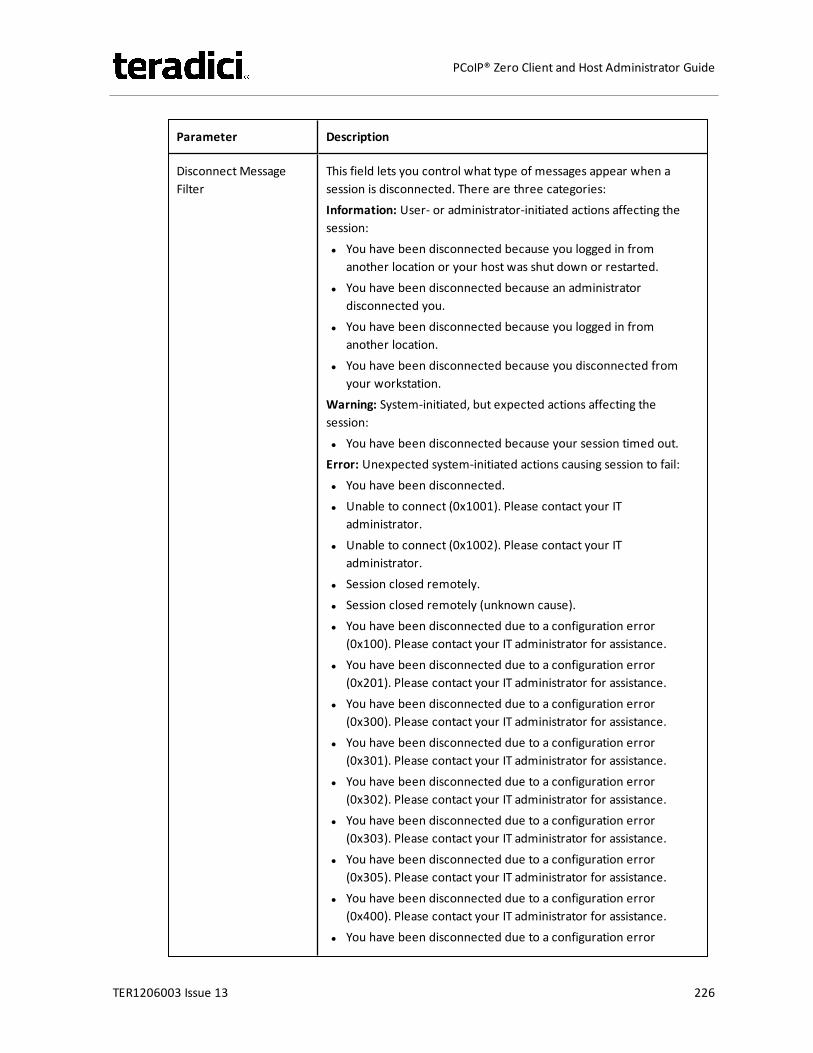
Parameter Description
Disconnect MessageFilter
This field lets you control what type of messages appear when asession is disconnected. There are three categories:Information: User- or administrator-initiated actions affecting thesession:l You have been disconnected because you logged in from
another location or your host was shut down or restarted.l You have been disconnected because an administrator
disconnected you.l You have been disconnected because you logged in from
another location.l You have been disconnected because you disconnected from
your workstation.Warning: System-initiated, but expected actions affecting thesession:l You have been disconnected because your session timed out.Error: Unexpected system-initiated actions causing session to fail:l You have been disconnected.l Unable to connect (0x1001). Please contact your IT
administrator.l Unable to connect (0x1002). Please contact your IT
administrator.l Session closed remotely.l Session closed remotely (unknown cause).l You have been disconnected due to a configuration error
(0x100). Please contact your IT administrator for assistance.l You have been disconnected due to a configuration error
(0x201). Please contact your IT administrator for assistance.l You have been disconnected due to a configuration error
(0x300). Please contact your IT administrator for assistance.l You have been disconnected due to a configuration error
(0x301). Please contact your IT administrator for assistance.l You have been disconnected due to a configuration error
(0x302). Please contact your IT administrator for assistance.l You have been disconnected due to a configuration error
(0x303). Please contact your IT administrator for assistance.l You have been disconnected due to a configuration error
(0x305). Please contact your IT administrator for assistance.l You have been disconnected due to a configuration error
(0x400). Please contact your IT administrator for assistance.l You have been disconnected due to a configuration error
TER1206003 Issue 13 226
PCoIP® Zero Client and Host Administrator Guide
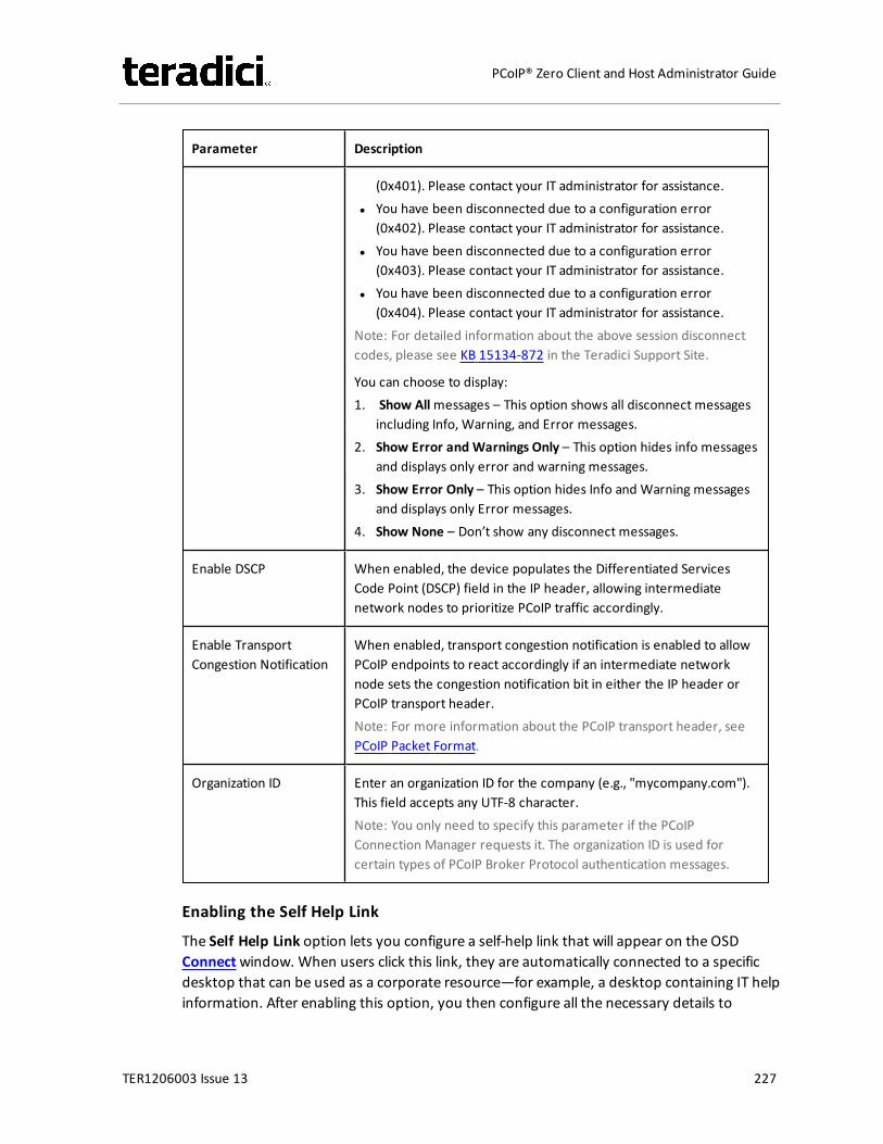
Parameter Description
(0x401). Please contact your IT administrator for assistance.l You have been disconnected due to a configuration error
(0x402). Please contact your IT administrator for assistance.l You have been disconnected due to a configuration error
(0x403). Please contact your IT administrator for assistance.l You have been disconnected due to a configuration error
(0x404). Please contact your IT administrator for assistance.Note: For detailed information about the above session disconnectcodes, please see KB 15134-872 in the Teradici Support Site.
You can choose to display:1. Show Allmessages – This option shows all disconnect messages
including Info, Warning, and Error messages.2. Show Error and Warnings Only – This option hides info messages
and displays only error and warning messages.3. Show Error Only – This option hides Info and Warning messages
and displays only Error messages.4. Show None – Don’t show any disconnect messages.
Enable DSCP When enabled, the device populates the Differentiated ServicesCode Point (DSCP) field in the IP header, allowing intermediatenetwork nodes to prioritize PCoIP traffic accordingly.
Enable TransportCongestion Notification
When enabled, transport congestion notification is enabled to allowPCoIP endpoints to react accordingly if an intermediate networknode sets the congestion notification bit in either the IP header orPCoIP transport header.Note: For more information about the PCoIP transport header, seePCoIP Packet Format.
Organization ID Enter an organization ID for the company (e.g., "mycompany.com").This field accepts any UTF-8 character.Note: You only need to specify this parameter if the PCoIPConnection Manager requests it. The organization ID is used forcertain types of PCoIP Broker Protocol authentication messages.
Enabling the Self Help Link
The Self Help Link option lets you configure a self-help link that will appear on the OSDConnectwindow. When users click this link, they are automatically connected to a specificdesktop that can be used as a corporate resource—for example, a desktop containing IT helpinformation. After enabling this option, you then configure all the necessary details to
TER1206003 Issue 13 227
PCoIP® Zero Client and Host Administrator Guide
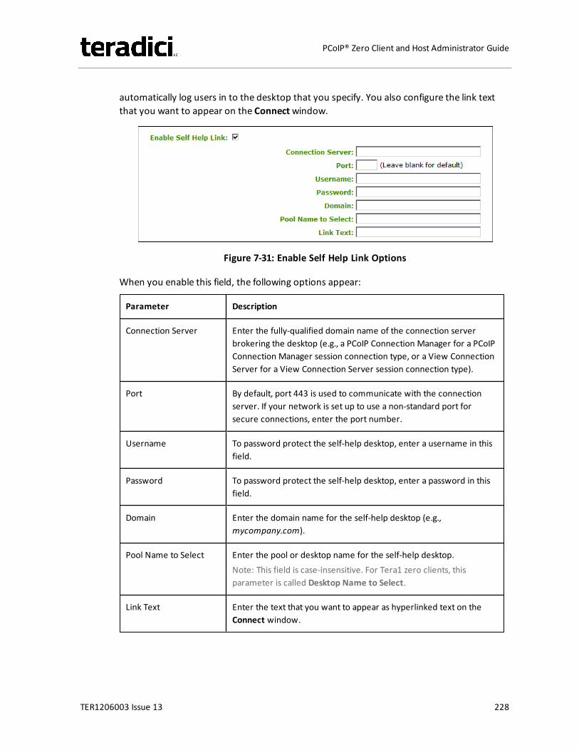
automatically log users in to the desktop that you specify. You also configure the link textthat you want to appear on the Connectwindow.
Figure 7-31: Enable Self Help Link Options
When you enable this field, the following options appear:
Parameter Description
Connection Server Enter the fully-qualified domain name of the connection serverbrokering the desktop (e.g., a PCoIP Connection Manager for a PCoIPConnection Manager session connection type, or a View ConnectionServer for a View Connection Server session connection type).
Port By default, port 443 is used to communicate with the connectionserver. If your network is set up to use a non-standard port forsecure connections, enter the port number.
Username To password protect the self-help desktop, enter a username in thisfield.
Password To password protect the self-help desktop, enter a password in thisfield.
Domain Enter the domain name for the self-help desktop (e.g.,mycompany.com).
Pool Name to Select Enter the pool or desktop name for the self-help desktop.Note: This field is case-insensitive. For Tera1 zero clients, thisparameter is called Desktop Name to Select.
Link Text Enter the text that you want to appear as hyperlinked text on theConnect window.
TER1206003 Issue 13 228
PCoIP® Zero Client and Host Administrator Guide
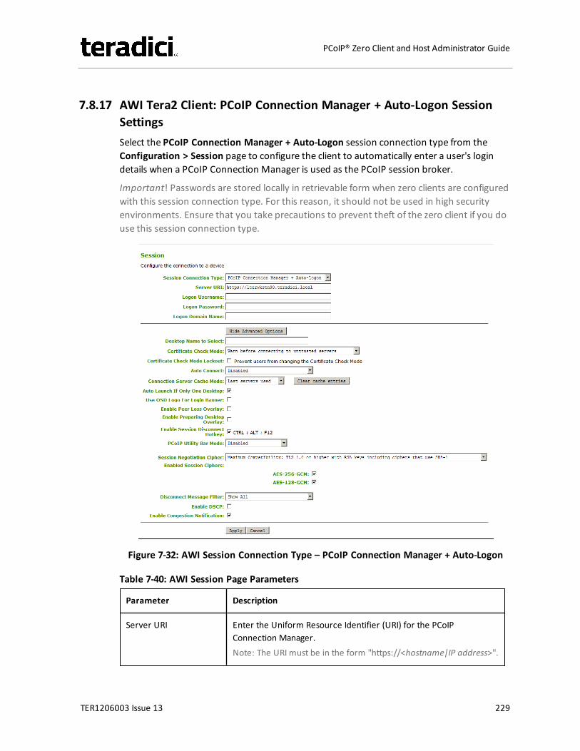
7.8.17 AWI Tera2 Client: PCoIP Connection Manager + Auto-Logon SessionSettingsSelect the PCoIP Connection Manager + Auto-Logon session connection type from theConfiguration > Session page to configure the client to automatically enter a user's logindetails when a PCoIP Connection Manager is used as the PCoIP session broker.
Important! Passwords are stored locally in retrievable form when zero clients are configuredwith this session connection type. For this reason, it should not be used in high securityenvironments. Ensure that you take precautions to prevent theft of the zero client if you douse this session connection type.
Figure 7-32: AWI Session Connection Type – PCoIP Connection Manager + Auto-Logon
Table 7-40: AWI Session Page Parameters
Parameter Description
Server URI Enter the Uniform Resource Identifier (URI) for the PCoIPConnection Manager.Note: The URI must be in the form "https://<hostname|IP address>".
TER1206003 Issue 13 229
PCoIP® Zero Client and Host Administrator Guide
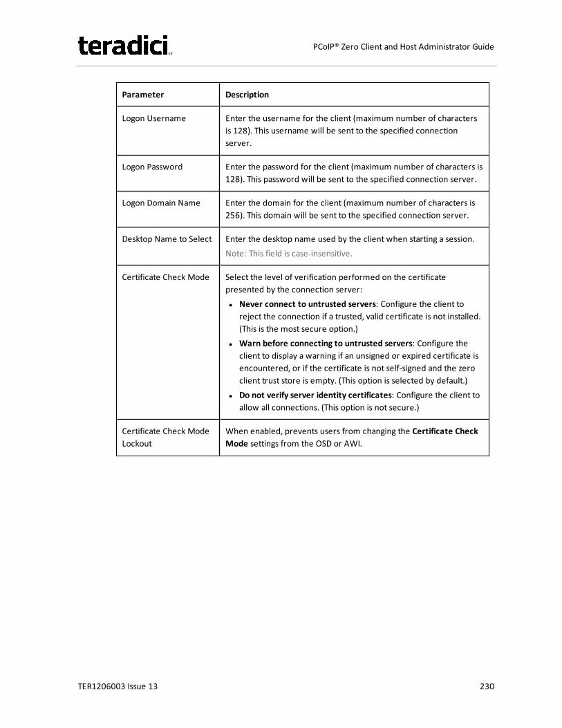
Parameter Description
Logon Username Enter the username for the client (maximum number of charactersis 128). This username will be sent to the specified connectionserver.
Logon Password Enter the password for the client (maximum number of characters is128). This password will be sent to the specified connection server.
Logon Domain Name Enter the domain for the client (maximum number of characters is256). This domain will be sent to the specified connection server.
Desktop Name to Select Enter the desktop name used by the client when starting a session.Note: This field is case-insensitive.
Certificate Check Mode Select the level of verification performed on the certificatepresented by the connection server:l Never connect to untrusted servers: Configure the client to
reject the connection if a trusted, valid certificate is not installed.(This is the most secure option.)
l Warn before connecting to untrusted servers: Configure theclient to display a warning if an unsigned or expired certificate isencountered, or if the certificate is not self-signed and the zeroclient trust store is empty. (This option is selected by default.)
l Do not verify server identity certificates: Configure the client toallow all connections. (This option is not secure.)
Certificate Check ModeLockout
When enabled, prevents users from changing the Certificate CheckMode settings from the OSD or AWI.
TER1206003 Issue 13 230
PCoIP® Zero Client and Host Administrator Guide
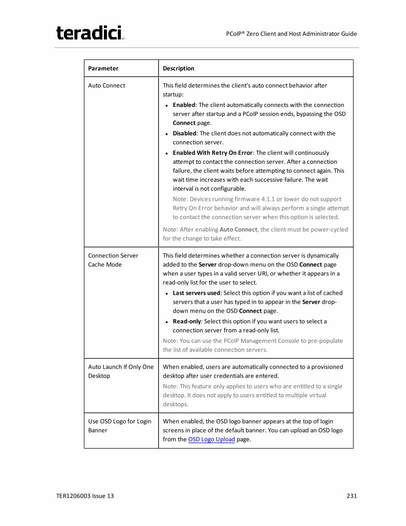
Parameter Description
Auto Connect This field determines the client's auto connect behavior afterstartup:l Enabled: The client automatically connects with the connection
server after startup and a PCoIP session ends, bypassing the OSDConnect page.
l Disabled: The client does not automatically connect with theconnection server.
l Enabled With Retry On Error: The client will continuouslyattempt to contact the connection server. After a connectionfailure, the client waits before attempting to connect again. Thiswait time increases with each successive failure. The waitinterval is not configurable.Note: Devices running firmware 4.1.1 or lower do not supportRetry On Error behavior and will always perform a single attemptto contact the connection server when this option is selected.
Note: After enabling Auto Connect, the client must be power-cycledfor the change to take effect.
Connection ServerCache Mode
This field determines whether a connection server is dynamicallyadded to the Server drop-down menu on the OSD Connect pagewhen a user types in a valid server URI, or whether it appears in aread-only list for the user to select.l Last servers used: Select this option if you want a list of cached
servers that a user has typed in to appear in the Server drop-down menu on the OSD Connect page.
l Read-only: Select this option if you want users to select aconnection server from a read-only list.
Note: You can use the PCoIP Management Console to pre-populatethe list of available connection servers.
Auto Launch If Only OneDesktop
When enabled, users are automatically connected to a provisioneddesktop after user credentials are entered.Note: This feature only applies to users who are entitled to a singledesktop. It does not apply to users entitled to multiple virtualdesktops.
Use OSD Logo for LoginBanner
When enabled, the OSD logo banner appears at the top of loginscreens in place of the default banner. You can upload an OSD logofrom the OSD Logo Upload page.
TER1206003 Issue 13 231
PCoIP® Zero Client and Host Administrator Guide

Parameter Description
Enable Peer LossOverlay
When enabled, the “Network Connection Lost” overlay appears onthe display(s) when a loss of network connectivity is detected.Normal hypervisor scheduling delays can falsely trigger this message.
Note: This option is only available for a zero client. Desktopapplications that require the peer loss notification should re-enablethe feature through the OSD, AWI, or MC.
Enable PreparingDesktop Overlay
When enabled, the "Preparing Desktop" overlay appears on thedisplay(s) when users log in.Note: This overlay provides assurance that login is proceeding if thedesktop takes more than a few seconds to appear.
Enable SessionDisconnect Hotkey
When enabled, users can press the Ctrl+Alt+F12 hotkey sequence topop up the "Zero Client Control Panel" overlay, which lets themdisconnect the current session on the workstation or power off theworkstation.Note: Before users can use this disconnect hotkey sequence, certainother configuration options must be in place. See Disconnectingfrom a Session for details.
PCoIP Utility Bar Mode(Tera2 zero clients only)
When enabled, the PCoIP Utility Bar appears at the top of theprimary display when a user is in session and moves the cursordirectly under the bar. The utility bar can be used to disconnect asession or to shut down a remote workstation. For Direct to Hostsession connection types, Local Cursor and Keyboard must beenabled in order for the zero client to process mouse events for theutility bar. For all connection types, the mouse must be locallyconnected (i.e., not bridged).l Disabled: Disables the PCoIP Utility Bar. Note: (By default, the
utility bar is disabled.)l Enabled: Enables and auto-hides the PCoIP Utility Bar. Users can
show the utility bar by pointing the mouse at the top of thescreen directly under the utility bar. Users can slide the utility barto the right and left at the top of the screen.
l Enabled and Pinned: Enables and pins the PCoIP Utility Bar at thetop of the screen. Users cannot hide the utility bar, but they canslide it to the right and left at the top of the screen.
Note: This feature is configurable from the MC and AWI only. Itrequires firmware version 4.2.0 or newer.
TER1206003 Issue 13 232
PCoIP® Zero Client and Host Administrator Guide

Parameter Description
Session NegotiationCipher
Important: In release 4.8.0, the security cipher features listed beloware supported on Tera2 zero clients only. In order to use a non-SHA-1 cipher, both the client and host endpoints must support it.
Note: For sessions with software hosts, the zero client should beconfigured to use the Maximum Compatibility option.
For Tera2 zero clients:Configure the Transport Layer Security (TLS) cipher to use fornegotiating the TLS session between the PCoIP client and the PCoIPhost.l Maximum Compatibility: TLS 1.0 or higher with RSA keys
including ciphers that use SHA-1: This option provides maximumcompatibility.
l Suite B: TLS 1.2 with Suite B-compliant 192-bit elliptic curveencryption. This option provides a higher level of security.
l Disable SHA-1: TLS 1.2 with RSA keys and strong ciphers usingonly SHA-256 or SHA-384: When selected, only devices runningfirmware 4.8.0 or greater are affected.Note: Currently this option can only be used with AmazonWorkSpaces hosts.
For Tera1 zero clients:Configure the Transport Layer Security (TLS) cipher to use fornegotiating the TLS session between the PCoIP client and the PCoIPhost.l Maximum Compatibility: TLS 1.0 with RSA keys and AES-256 or
AES-128 encryption: This option provides maximumcompatibility.
l Suite B: TLS 1.2 with Suite B-compliant 192-bit elliptic curveencryption. This option provides a higher level of security.
TER1206003 Issue 13 233
PCoIP® Zero Client and Host Administrator Guide
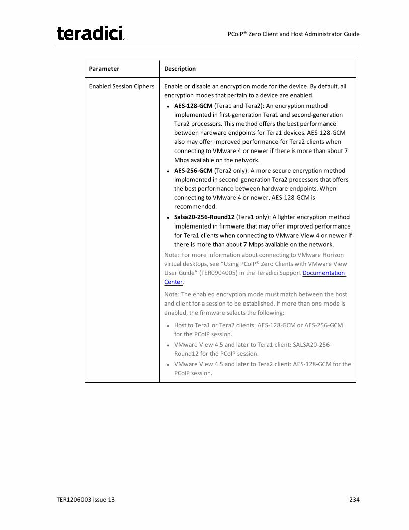
Parameter Description
Enabled Session Ciphers Enable or disable an encryption mode for the device. By default, allencryption modes that pertain to a device are enabled.l AES-128-GCM (Tera1 and Tera2): An encryption method
implemented in first-generation Tera1 and second-generationTera2 processors. This method offers the best performancebetween hardware endpoints for Tera1 devices. AES-128-GCMalso may offer improved performance for Tera2 clients whenconnecting to VMware 4 or newer if there is more than about 7Mbps available on the network.
l AES-256-GCM (Tera2 only): A more secure encryption methodimplemented in second-generation Tera2 processors that offersthe best performance between hardware endpoints. Whenconnecting to VMware 4 or newer, AES-128-GCM isrecommended.
l Salsa20-256-Round12 (Tera1 only): A lighter encryption methodimplemented in firmware that may offer improved performancefor Tera1 clients when connecting to VMware View 4 or newer ifthere is more than about 7 Mbps available on the network.
Note: For more information about connecting to VMware Horizonvirtual desktops, see “Using PCoIP® Zero Clients with VMware ViewUser Guide” (TER0904005) in the Teradici Support DocumentationCenter.
Note: The enabled encryption mode must match between the hostand client for a session to be established. If more than one mode isenabled, the firmware selects the following:
l Host to Tera1 or Tera2 clients: AES-128-GCM or AES-256-GCMfor the PCoIP session.
l VMware View 4.5 and later to Tera1 client: SALSA20-256-Round12 for the PCoIP session.
l VMware View 4.5 and later to Tera2 client: AES-128-GCM for thePCoIP session.
TER1206003 Issue 13 234
PCoIP® Zero Client and Host Administrator Guide

Parameter Description
Disconnect MessageFilter
This field lets you control what type of messages appear when asession is disconnected. There are three categories:Information: User- or administrator-initiated actions affecting thesession:l You have been disconnected because you logged in from
another location or your host was shut down or restarted.l You have been disconnected because an administrator
disconnected you.l You have been disconnected because you logged in from
another location.l You have been disconnected because you disconnected from
your workstation.Warning: System-initiated, but expected actions affecting thesession:l You have been disconnected because your session timed out.Error: Unexpected system-initiated actions causing session to fail:l You have been disconnected.l Unable to connect (0x1001). Please contact your IT
administrator.l Unable to connect (0x1002). Please contact your IT
administrator.l Session closed remotely.l Session closed remotely (unknown cause).l You have been disconnected due to a configuration error
(0x100). Please contact your IT administrator for assistance.l You have been disconnected due to a configuration error
(0x201). Please contact your IT administrator for assistance.l You have been disconnected due to a configuration error
(0x300). Please contact your IT administrator for assistance.l You have been disconnected due to a configuration error
(0x301). Please contact your IT administrator for assistance.l You have been disconnected due to a configuration error
(0x302). Please contact your IT administrator for assistance.l You have been disconnected due to a configuration error
(0x303). Please contact your IT administrator for assistance.l You have been disconnected due to a configuration error
(0x305). Please contact your IT administrator for assistance.l You have been disconnected due to a configuration error
(0x400). Please contact your IT administrator for assistance.l You have been disconnected due to a configuration error
TER1206003 Issue 13 235
PCoIP® Zero Client and Host Administrator Guide
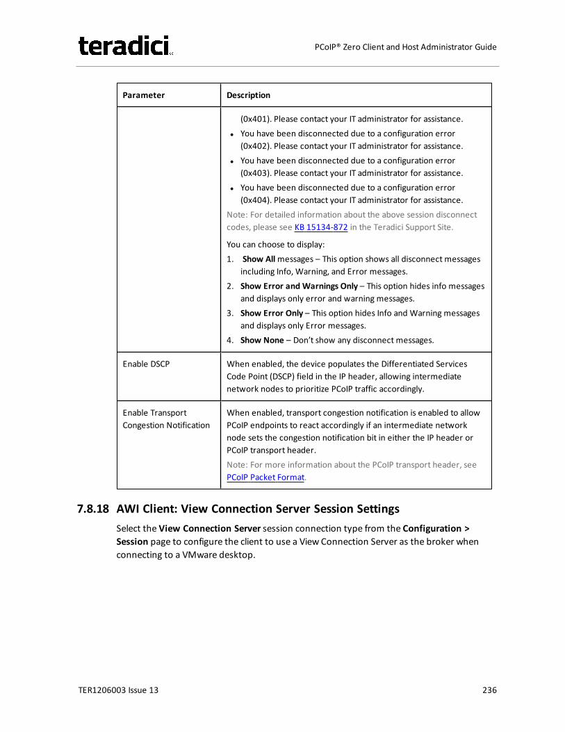
Parameter Description
(0x401). Please contact your IT administrator for assistance.l You have been disconnected due to a configuration error
(0x402). Please contact your IT administrator for assistance.l You have been disconnected due to a configuration error
(0x403). Please contact your IT administrator for assistance.l You have been disconnected due to a configuration error
(0x404). Please contact your IT administrator for assistance.Note: For detailed information about the above session disconnectcodes, please see KB 15134-872 in the Teradici Support Site.
You can choose to display:1. Show Allmessages – This option shows all disconnect messages
including Info, Warning, and Error messages.2. Show Error and Warnings Only – This option hides info messages
and displays only error and warning messages.3. Show Error Only – This option hides Info and Warning messages
and displays only Error messages.4. Show None – Don’t show any disconnect messages.
Enable DSCP When enabled, the device populates the Differentiated ServicesCode Point (DSCP) field in the IP header, allowing intermediatenetwork nodes to prioritize PCoIP traffic accordingly.
Enable TransportCongestion Notification
When enabled, transport congestion notification is enabled to allowPCoIP endpoints to react accordingly if an intermediate networknode sets the congestion notification bit in either the IP header orPCoIP transport header.Note: For more information about the PCoIP transport header, seePCoIP Packet Format.
7.8.18 AWI Client: View Connection Server Session SettingsSelect the View Connection Server session connection type from the Configuration >Session page to configure the client to use a View Connection Server as the broker whenconnecting to a VMware desktop.
TER1206003 Issue 13 236
PCoIP® Zero Client and Host Administrator Guide
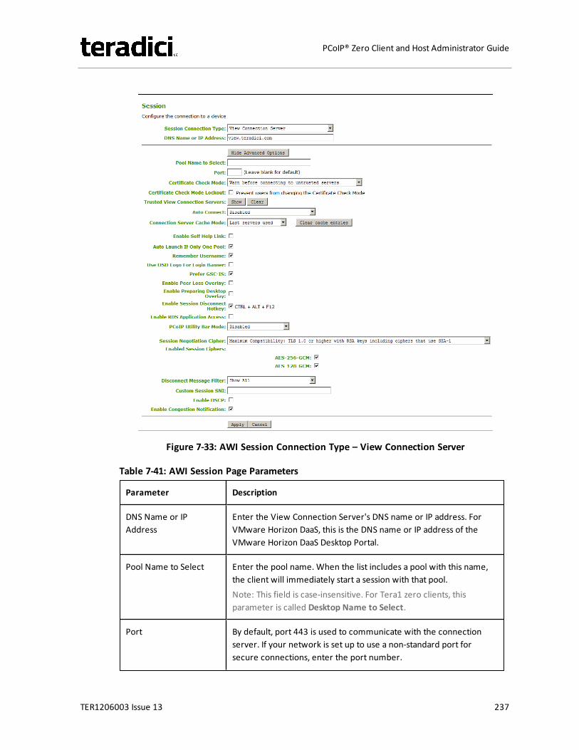
Figure 7-33: AWI Session Connection Type – View Connection Server
Table 7-41: AWI Session Page Parameters
Parameter Description
DNS Name or IPAddress
Enter the View Connection Server's DNS name or IP address. ForVMware Horizon DaaS, this is the DNS name or IP address of theVMware Horizon DaaS Desktop Portal.
Pool Name to Select Enter the pool name. When the list includes a pool with this name,the client will immediately start a session with that pool.Note: This field is case-insensitive. For Tera1 zero clients, thisparameter is called Desktop Name to Select.
Port By default, port 443 is used to communicate with the connectionserver. If your network is set up to use a non-standard port forsecure connections, enter the port number.
TER1206003 Issue 13 237
PCoIP® Zero Client and Host Administrator Guide
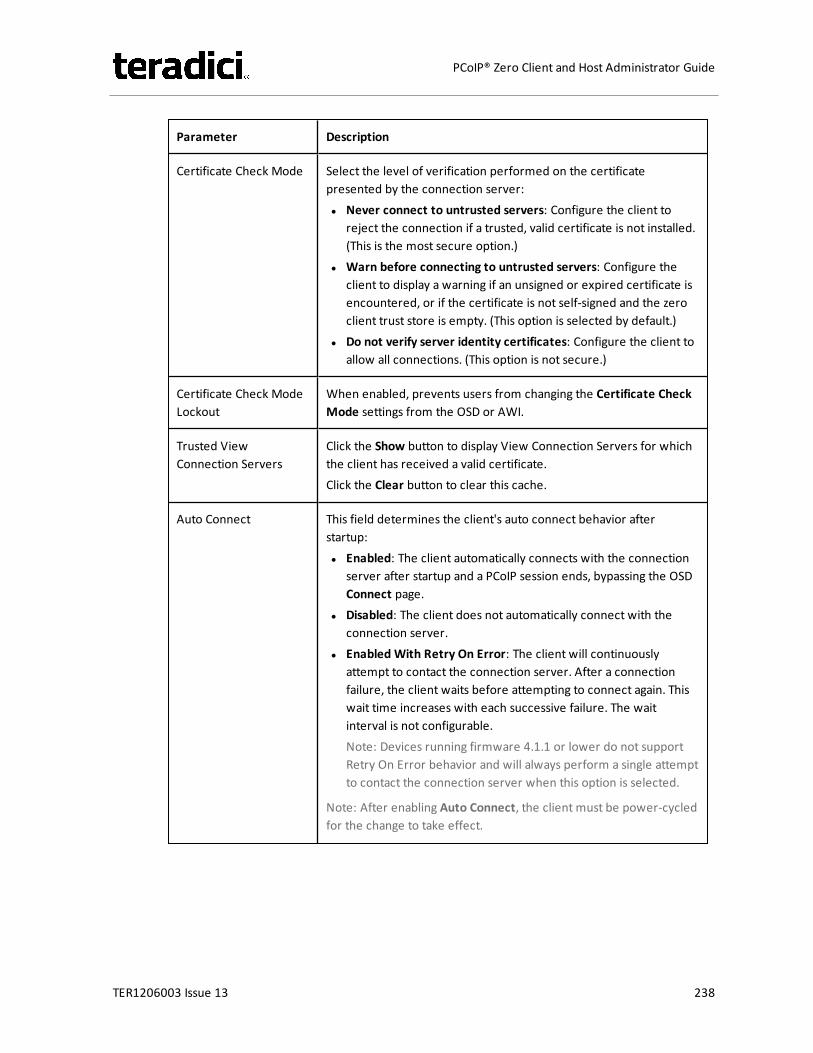
Parameter Description
Certificate Check Mode Select the level of verification performed on the certificatepresented by the connection server:l Never connect to untrusted servers: Configure the client to
reject the connection if a trusted, valid certificate is not installed.(This is the most secure option.)
l Warn before connecting to untrusted servers: Configure theclient to display a warning if an unsigned or expired certificate isencountered, or if the certificate is not self-signed and the zeroclient trust store is empty. (This option is selected by default.)
l Do not verify server identity certificates: Configure the client toallow all connections. (This option is not secure.)
Certificate Check ModeLockout
When enabled, prevents users from changing the Certificate CheckMode settings from the OSD or AWI.
Trusted ViewConnection Servers
Click the Show button to display View Connection Servers for whichthe client has received a valid certificate.Click the Clear button to clear this cache.
Auto Connect This field determines the client's auto connect behavior afterstartup:l Enabled: The client automatically connects with the connection
server after startup and a PCoIP session ends, bypassing the OSDConnect page.
l Disabled: The client does not automatically connect with theconnection server.
l Enabled With Retry On Error: The client will continuouslyattempt to contact the connection server. After a connectionfailure, the client waits before attempting to connect again. Thiswait time increases with each successive failure. The waitinterval is not configurable.Note: Devices running firmware 4.1.1 or lower do not supportRetry On Error behavior and will always perform a single attemptto contact the connection server when this option is selected.
Note: After enabling Auto Connect, the client must be power-cycledfor the change to take effect.
TER1206003 Issue 13 238
PCoIP® Zero Client and Host Administrator Guide
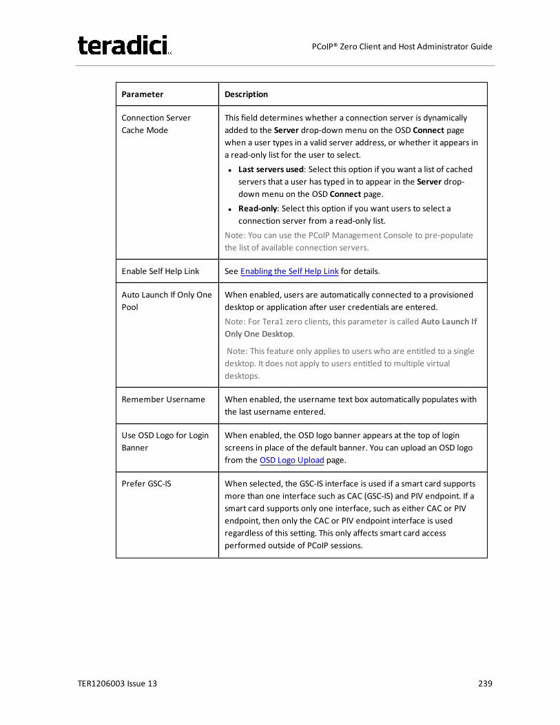
Parameter Description
Connection ServerCache Mode
This field determines whether a connection server is dynamicallyadded to the Server drop-down menu on the OSD Connect pagewhen a user types in a valid server address, or whether it appears ina read-only list for the user to select.l Last servers used: Select this option if you want a list of cached
servers that a user has typed in to appear in the Server drop-down menu on the OSD Connect page.
l Read-only: Select this option if you want users to select aconnection server from a read-only list.
Note: You can use the PCoIP Management Console to pre-populatethe list of available connection servers.
Enable Self Help Link See Enabling the Self Help Link for details.
Auto Launch If Only OnePool
When enabled, users are automatically connected to a provisioneddesktop or application after user credentials are entered.Note: For Tera1 zero clients, this parameter is called Auto Launch IfOnly One Desktop.
Note: This feature only applies to users who are entitled to a singledesktop. It does not apply to users entitled to multiple virtualdesktops.
Remember Username When enabled, the username text box automatically populates withthe last username entered.
Use OSD Logo for LoginBanner
When enabled, the OSD logo banner appears at the top of loginscreens in place of the default banner. You can upload an OSD logofrom the OSD Logo Upload page.
Prefer GSC-IS When selected, the GSC-IS interface is used if a smart card supportsmore than one interface such as CAC (GSC-IS) and PIV endpoint. If asmart card supports only one interface, such as either CAC or PIVendpoint, then only the CAC or PIV endpoint interface is usedregardless of this setting. This only affects smart card accessperformed outside of PCoIP sessions.
TER1206003 Issue 13 239
PCoIP® Zero Client and Host Administrator Guide
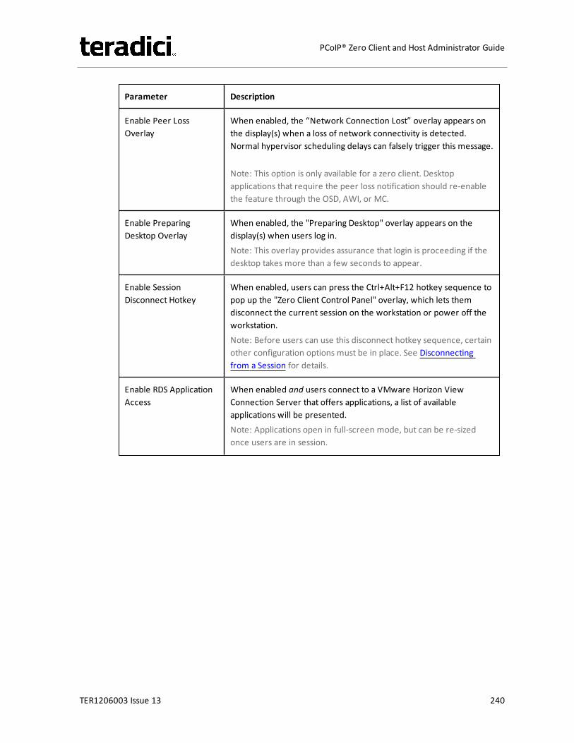
Parameter Description
Enable Peer LossOverlay
When enabled, the “Network Connection Lost” overlay appears onthe display(s) when a loss of network connectivity is detected.Normal hypervisor scheduling delays can falsely trigger this message.
Note: This option is only available for a zero client. Desktopapplications that require the peer loss notification should re-enablethe feature through the OSD, AWI, or MC.
Enable PreparingDesktop Overlay
When enabled, the "Preparing Desktop" overlay appears on thedisplay(s) when users log in.Note: This overlay provides assurance that login is proceeding if thedesktop takes more than a few seconds to appear.
Enable SessionDisconnect Hotkey
When enabled, users can press the Ctrl+Alt+F12 hotkey sequence topop up the "Zero Client Control Panel" overlay, which lets themdisconnect the current session on the workstation or power off theworkstation.Note: Before users can use this disconnect hotkey sequence, certainother configuration options must be in place. See Disconnectingfrom a Session for details.
Enable RDS ApplicationAccess
When enabled and users connect to a VMware Horizon ViewConnection Server that offers applications, a list of availableapplications will be presented.Note: Applications open in full-screen mode, but can be re-sizedonce users are in session.
TER1206003 Issue 13 240
PCoIP® Zero Client and Host Administrator Guide

Parameter Description
PCoIP Utility Bar Mode(Tera2 zero clients only)
When enabled, the PCoIP Utility Bar appears at the top of theprimary display when a user is in session and moves the cursordirectly under the bar. The utility bar can be used to disconnect asession or to shut down a remote workstation. For Direct to Hostsession connection types, Local Cursor and Keyboard must beenabled in order for the zero client to process mouse events for theutility bar. For all connection types, the mouse must be locallyconnected (i.e., not bridged).l Disabled: Disables the PCoIP Utility Bar. Note: (By default, the
utility bar is disabled.)l Enabled: Enables and auto-hides the PCoIP Utility Bar. Users can
show the utility bar by pointing the mouse at the top of thescreen directly under the utility bar. Users can slide the utility barto the right and left at the top of the screen.
l Enabled and Pinned: Enables and pins the PCoIP Utility Bar at thetop of the screen. Users cannot hide the utility bar, but they canslide it to the right and left at the top of the screen.
Note: This feature is configurable from the MC and AWI only. Itrequires firmware version 4.2.0 or newer.
TER1206003 Issue 13 241
PCoIP® Zero Client and Host Administrator Guide
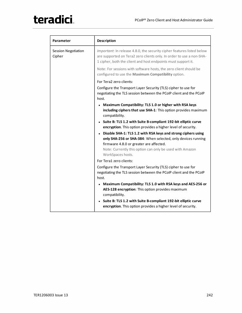
Parameter Description
Session NegotiationCipher
Important: In release 4.8.0, the security cipher features listed beloware supported on Tera2 zero clients only. In order to use a non-SHA-1 cipher, both the client and host endpoints must support it.
Note: For sessions with software hosts, the zero client should beconfigured to use the Maximum Compatibility option.
For Tera2 zero clients:Configure the Transport Layer Security (TLS) cipher to use fornegotiating the TLS session between the PCoIP client and the PCoIPhost.l Maximum Compatibility: TLS 1.0 or higher with RSA keys
including ciphers that use SHA-1: This option provides maximumcompatibility.
l Suite B: TLS 1.2 with Suite B-compliant 192-bit elliptic curveencryption. This option provides a higher level of security.
l Disable SHA-1: TLS 1.2 with RSA keys and strong ciphers usingonly SHA-256 or SHA-384: When selected, only devices runningfirmware 4.8.0 or greater are affected.Note: Currently this option can only be used with AmazonWorkSpaces hosts.
For Tera1 zero clients:Configure the Transport Layer Security (TLS) cipher to use fornegotiating the TLS session between the PCoIP client and the PCoIPhost.l Maximum Compatibility: TLS 1.0 with RSA keys and AES-256 or
AES-128 encryption: This option provides maximumcompatibility.
l Suite B: TLS 1.2 with Suite B-compliant 192-bit elliptic curveencryption. This option provides a higher level of security.
TER1206003 Issue 13 242
PCoIP® Zero Client and Host Administrator Guide

Parameter Description
Enabled Session Ciphers Enable or disable an encryption mode for the device. By default, allencryption modes that pertain to a device are enabled.l AES-128-GCM (Tera1 and Tera2): An encryption method
implemented in first-generation Tera1 and second-generationTera2 processors. This method offers the best performancebetween hardware endpoints for Tera1 devices. AES-128-GCMalso may offer improved performance for Tera2 clients whenconnecting to VMware 4 or newer if there is more than about 7Mbps available on the network.
l AES-256-GCM (Tera2 only): A more secure encryption methodimplemented in second-generation Tera2 processors that offersthe best performance between hardware endpoints. Whenconnecting to VMware 4 or newer, AES-128-GCM isrecommended.
l Salsa20-256-Round12 (Tera1 only): A lighter encryption methodimplemented in firmware that may offer improved performancefor Tera1 clients when connecting to VMware View 4 or newer ifthere is more than about 7 Mbps available on the network.
Note: For more information about connecting to VMware Horizonvirtual desktops, see “Using PCoIP® Zero Clients with VMware ViewUser Guide” (TER0904005) in the Teradici Support DocumentationCenter.
Note: The enabled encryption mode must match between the hostand client for a session to be established. If more than one mode isenabled, the firmware selects the following:
l Host to Tera1 or Tera2 clients: AES-128-GCM or AES-256-GCMfor the PCoIP session.
l VMware View 4.5 and later to Tera1 client: SALSA20-256-Round12 for the PCoIP session.
l VMware View 4.5 and later to Tera2 client: AES-128-GCM for thePCoIP session.
TER1206003 Issue 13 243
PCoIP® Zero Client and Host Administrator Guide

Parameter Description
Disconnect MessageFilter
This field lets you control what type of messages appear when asession is disconnected. There are three categories:Information: User- or administrator-initiated actions affecting thesession:l You have been disconnected because you logged in from
another location or your host was shut down or restarted.l You have been disconnected because an administrator
disconnected you.l You have been disconnected because you logged in from
another location.l You have been disconnected because you disconnected from
your workstation.Warning: System-initiated, but expected actions affecting thesession:l You have been disconnected because your session timed out.Error: Unexpected system-initiated actions causing session to fail:l You have been disconnected.l Unable to connect (0x1001). Please contact your IT
administrator.l Unable to connect (0x1002). Please contact your IT
administrator.l Session closed remotely.l Session closed remotely (unknown cause).l You have been disconnected due to a configuration error
(0x100). Please contact your IT administrator for assistance.l You have been disconnected due to a configuration error
(0x201). Please contact your IT administrator for assistance.l You have been disconnected due to a configuration error
(0x300). Please contact your IT administrator for assistance.l You have been disconnected due to a configuration error
(0x301). Please contact your IT administrator for assistance.l You have been disconnected due to a configuration error
(0x302). Please contact your IT administrator for assistance.l You have been disconnected due to a configuration error
(0x303). Please contact your IT administrator for assistance.l You have been disconnected due to a configuration error
(0x305). Please contact your IT administrator for assistance.l You have been disconnected due to a configuration error
(0x400). Please contact your IT administrator for assistance.l You have been disconnected due to a configuration error
TER1206003 Issue 13 244
PCoIP® Zero Client and Host Administrator Guide
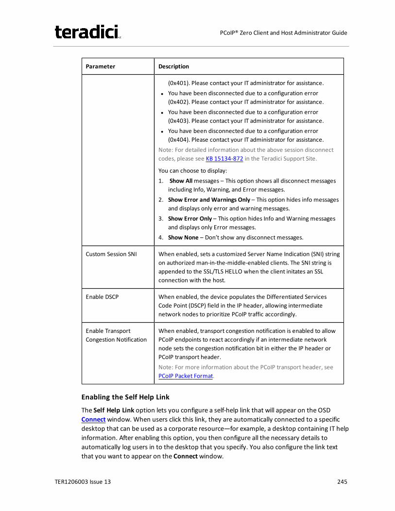
Parameter Description
(0x401). Please contact your IT administrator for assistance.l You have been disconnected due to a configuration error
(0x402). Please contact your IT administrator for assistance.l You have been disconnected due to a configuration error
(0x403). Please contact your IT administrator for assistance.l You have been disconnected due to a configuration error
(0x404). Please contact your IT administrator for assistance.Note: For detailed information about the above session disconnectcodes, please see KB 15134-872 in the Teradici Support Site.
You can choose to display:1. Show Allmessages – This option shows all disconnect messages
including Info, Warning, and Error messages.2. Show Error and Warnings Only – This option hides info messages
and displays only error and warning messages.3. Show Error Only – This option hides Info and Warning messages
and displays only Error messages.4. Show None – Don’t show any disconnect messages.
Custom Session SNI When enabled, sets a customized Server Name Indication (SNI) stringon authorized man-in-the-middle-enabled clients. The SNI string isappended to the SSL/TLS HELLO when the client initates an SSLconnection with the host.
Enable DSCP When enabled, the device populates the Differentiated ServicesCode Point (DSCP) field in the IP header, allowing intermediatenetwork nodes to prioritize PCoIP traffic accordingly.
Enable TransportCongestion Notification
When enabled, transport congestion notification is enabled to allowPCoIP endpoints to react accordingly if an intermediate networknode sets the congestion notification bit in either the IP header orPCoIP transport header.Note: For more information about the PCoIP transport header, seePCoIP Packet Format.
Enabling the Self Help Link
The Self Help Link option lets you configure a self-help link that will appear on the OSDConnectwindow. When users click this link, they are automatically connected to a specificdesktop that can be used as a corporate resource—for example, a desktop containing IT helpinformation. After enabling this option, you then configure all the necessary details toautomatically log users in to the desktop that you specify. You also configure the link textthat you want to appear on the Connectwindow.
TER1206003 Issue 13 245
PCoIP® Zero Client and Host Administrator Guide
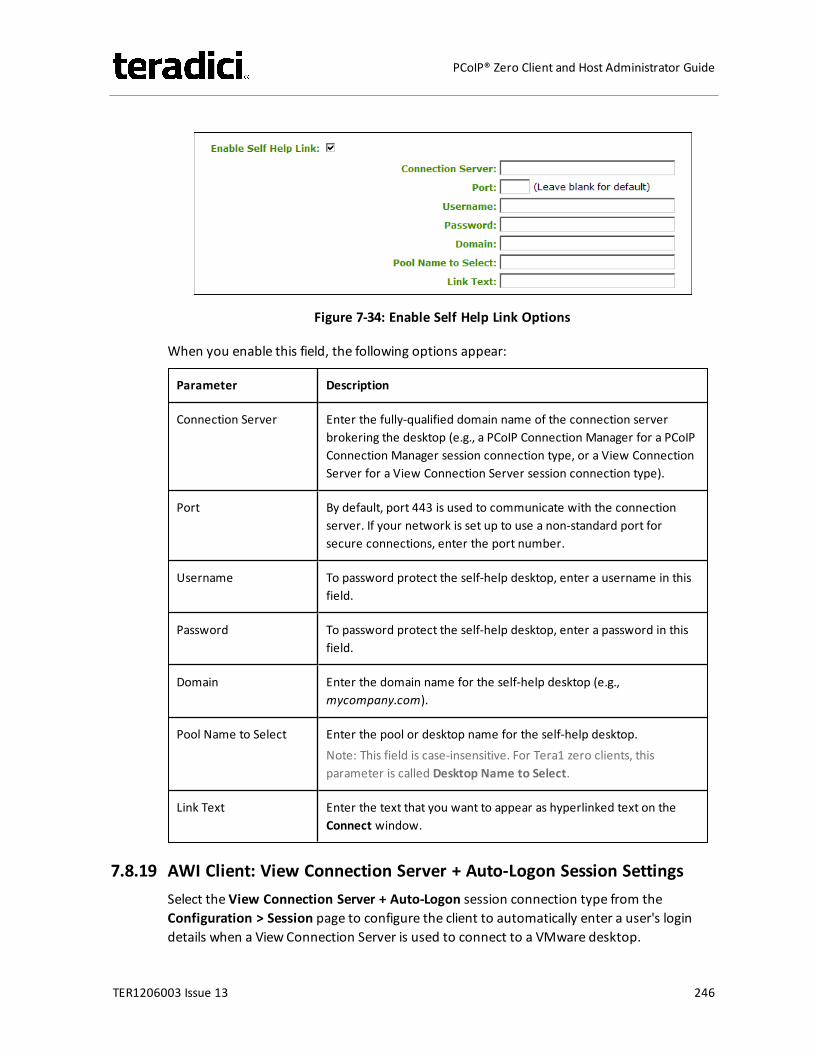
Figure 7-34: Enable Self Help Link Options
When you enable this field, the following options appear:
Parameter Description
Connection Server Enter the fully-qualified domain name of the connection serverbrokering the desktop (e.g., a PCoIP Connection Manager for a PCoIPConnection Manager session connection type, or a View ConnectionServer for a View Connection Server session connection type).
Port By default, port 443 is used to communicate with the connectionserver. If your network is set up to use a non-standard port forsecure connections, enter the port number.
Username To password protect the self-help desktop, enter a username in thisfield.
Password To password protect the self-help desktop, enter a password in thisfield.
Domain Enter the domain name for the self-help desktop (e.g.,mycompany.com).
Pool Name to Select Enter the pool or desktop name for the self-help desktop.Note: This field is case-insensitive. For Tera1 zero clients, thisparameter is called Desktop Name to Select.
Link Text Enter the text that you want to appear as hyperlinked text on theConnect window.
7.8.19 AWI Client: View Connection Server + Auto-Logon Session SettingsSelect the View Connection Server + Auto-Logon session connection type from theConfiguration > Session page to configure the client to automatically enter a user's logindetails when a View Connection Server is used to connect to a VMware desktop.
TER1206003 Issue 13 246
PCoIP® Zero Client and Host Administrator Guide
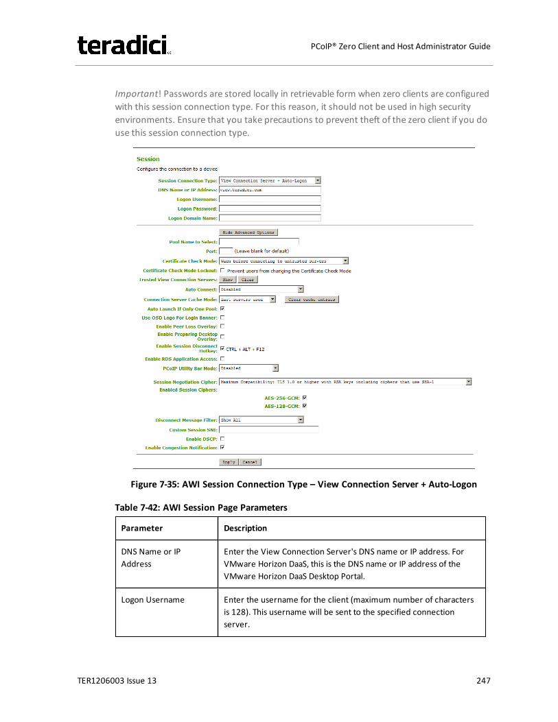
Important! Passwords are stored locally in retrievable form when zero clients are configuredwith this session connection type. For this reason, it should not be used in high securityenvironments. Ensure that you take precautions to prevent theft of the zero client if you douse this session connection type.
Figure 7-35: AWI Session Connection Type – View Connection Server + Auto-Logon
Table 7-42: AWI Session Page Parameters
Parameter Description
DNS Name or IPAddress
Enter the View Connection Server's DNS name or IP address. ForVMware Horizon DaaS, this is the DNS name or IP address of theVMware Horizon DaaS Desktop Portal.
Logon Username Enter the username for the client (maximum number of charactersis 128). This username will be sent to the specified connectionserver.
TER1206003 Issue 13 247
PCoIP® Zero Client and Host Administrator Guide
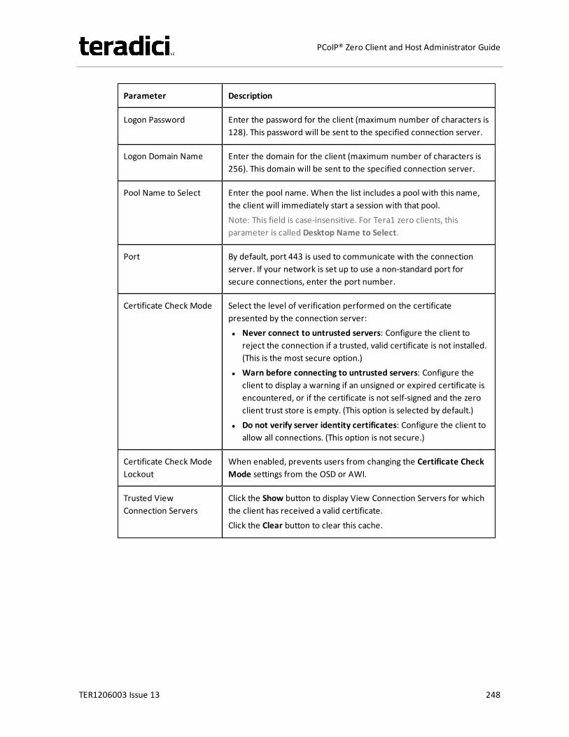
Parameter Description
Logon Password Enter the password for the client (maximum number of characters is128). This password will be sent to the specified connection server.
Logon Domain Name Enter the domain for the client (maximum number of characters is256). This domain will be sent to the specified connection server.
Pool Name to Select Enter the pool name. When the list includes a pool with this name,the client will immediately start a session with that pool.Note: This field is case-insensitive. For Tera1 zero clients, thisparameter is called Desktop Name to Select.
Port By default, port 443 is used to communicate with the connectionserver. If your network is set up to use a non-standard port forsecure connections, enter the port number.
Certificate Check Mode Select the level of verification performed on the certificatepresented by the connection server:l Never connect to untrusted servers: Configure the client to
reject the connection if a trusted, valid certificate is not installed.(This is the most secure option.)
l Warn before connecting to untrusted servers: Configure theclient to display a warning if an unsigned or expired certificate isencountered, or if the certificate is not self-signed and the zeroclient trust store is empty. (This option is selected by default.)
l Do not verify server identity certificates: Configure the client toallow all connections. (This option is not secure.)
Certificate Check ModeLockout
When enabled, prevents users from changing the Certificate CheckMode settings from the OSD or AWI.
Trusted ViewConnection Servers
Click the Show button to display View Connection Servers for whichthe client has received a valid certificate.Click the Clear button to clear this cache.
TER1206003 Issue 13 248
PCoIP® Zero Client and Host Administrator Guide
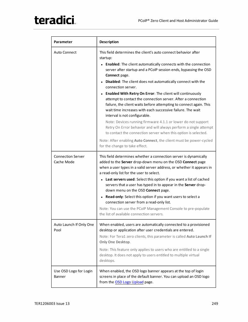
Parameter Description
Auto Connect This field determines the client's auto connect behavior afterstartup:l Enabled: The client automatically connects with the connection
server after startup and a PCoIP session ends, bypassing the OSDConnect page.
l Disabled: The client does not automatically connect with theconnection server.
l Enabled With Retry On Error: The client will continuouslyattempt to contact the connection server. After a connectionfailure, the client waits before attempting to connect again. Thiswait time increases with each successive failure. The waitinterval is not configurable.Note: Devices running firmware 4.1.1 or lower do not supportRetry On Error behavior and will always perform a single attemptto contact the connection server when this option is selected.
Note: After enabling Auto Connect, the client must be power-cycledfor the change to take effect.
Connection ServerCache Mode
This field determines whether a connection server is dynamicallyadded to the Server drop-down menu on the OSD Connect pagewhen a user types in a valid server address, or whether it appears ina read-only list for the user to select.l Last servers used: Select this option if you want a list of cached
servers that a user has typed in to appear in the Server drop-down menu on the OSD Connect page.
l Read-only: Select this option if you want users to select aconnection server from a read-only list.
Note: You can use the PCoIP Management Console to pre-populatethe list of available connection servers.
Auto Launch If Only OnePool
When enabled, users are automatically connected to a provisioneddesktop or application after user credentials are entered.Note: For Tera1 zero clients, this parameter is called Auto Launch IfOnly One Desktop.
Note: This feature only applies to users who are entitled to a singledesktop. It does not apply to users entitled to multiple virtualdesktops.
Use OSD Logo for LoginBanner
When enabled, the OSD logo banner appears at the top of loginscreens in place of the default banner. You can upload an OSD logofrom the OSD Logo Upload page.
TER1206003 Issue 13 249
PCoIP® Zero Client and Host Administrator Guide

Parameter Description
Enable Peer LossOverlay
When enabled, the “Network Connection Lost” overlay appears onthe display(s) when a loss of network connectivity is detected.Normal hypervisor scheduling delays can falsely trigger this message.
Note: This option is only available for a zero client. Desktopapplications that require the peer loss notification should re-enablethe feature through the OSD, AWI, or MC.
Enable PreparingDesktop Overlay
When enabled, the "Preparing Desktop" overlay appears on thedisplay(s) when users log in.Note: This overlay provides assurance that login is proceeding if thedesktop takes more than a few seconds to appear.
Enable SessionDisconnect Hotkey
When enabled, users can press the Ctrl+Alt+F12 hotkey sequence topop up the "Zero Client Control Panel" overlay, which lets themdisconnect the current session on the workstation or power off theworkstation.Note: Before users can use this disconnect hotkey sequence, certainother configuration options must be in place. See Disconnectingfrom a Session for details.
Enable RDS ApplicationAccess
When enabled and users connect to a VMware Horizon ViewConnection Server that offers applications, a list of availableapplications will be presented.Note: Applications open in full-screen mode, but can be re-sizedonce users are in session.
TER1206003 Issue 13 250
PCoIP® Zero Client and Host Administrator Guide

Parameter Description
PCoIP Utility Bar Mode(Tera2 zero clients only)
When enabled, the PCoIP Utility Bar appears at the top of theprimary display when a user is in session and moves the cursordirectly under the bar. The utility bar can be used to disconnect asession or to shut down a remote workstation. For Direct to Hostsession connection types, Local Cursor and Keyboard must beenabled in order for the zero client to process mouse events for theutility bar. For all connection types, the mouse must be locallyconnected (i.e., not bridged).l Disabled: Disables the PCoIP Utility Bar. Note: (By default, the
utility bar is disabled.)l Enabled: Enables and auto-hides the PCoIP Utility Bar. Users can
show the utility bar by pointing the mouse at the top of thescreen directly under the utility bar. Users can slide the utility barto the right and left at the top of the screen.
l Enabled and Pinned: Enables and pins the PCoIP Utility Bar at thetop of the screen. Users cannot hide the utility bar, but they canslide it to the right and left at the top of the screen.
Note: This feature is configurable from the MC and AWI only. Itrequires firmware version 4.2.0 or newer.
TER1206003 Issue 13 251
PCoIP® Zero Client and Host Administrator Guide

Parameter Description
Session NegotiationCipher
Important: In release 4.8.0, the security cipher features listed beloware supported on Tera2 zero clients only. In order to use a non-SHA-1 cipher, both the client and host endpoints must support it.
Note: For sessions with software hosts, the zero client should beconfigured to use the Maximum Compatibility option.
For Tera2 zero clients:Configure the Transport Layer Security (TLS) cipher to use fornegotiating the TLS session between the PCoIP client and the PCoIPhost.l Maximum Compatibility: TLS 1.0 or higher with RSA keys
including ciphers that use SHA-1: This option provides maximumcompatibility.
l Suite B: TLS 1.2 with Suite B-compliant 192-bit elliptic curveencryption. This option provides a higher level of security.
l Disable SHA-1: TLS 1.2 with RSA keys and strong ciphers usingonly SHA-256 or SHA-384: When selected, only devices runningfirmware 4.8.0 or greater are affected.Note: Currently this option can only be used with AmazonWorkSpaces hosts.
For Tera1 zero clients:Configure the Transport Layer Security (TLS) cipher to use fornegotiating the TLS session between the PCoIP client and the PCoIPhost.l Maximum Compatibility: TLS 1.0 with RSA keys and AES-256 or
AES-128 encryption: This option provides maximumcompatibility.
l Suite B: TLS 1.2 with Suite B-compliant 192-bit elliptic curveencryption. This option provides a higher level of security.
TER1206003 Issue 13 252
PCoIP® Zero Client and Host Administrator Guide

Parameter Description
Enabled Session Ciphers Enable or disable an encryption mode for the device. By default, allencryption modes that pertain to a device are enabled.l AES-128-GCM (Tera1 and Tera2): An encryption method
implemented in first-generation Tera1 and second-generationTera2 processors. This method offers the best performancebetween hardware endpoints for Tera1 devices. AES-128-GCMalso may offer improved performance for Tera2 clients whenconnecting to VMware 4 or newer if there is more than about 7Mbps available on the network.
l AES-256-GCM (Tera2 only): A more secure encryption methodimplemented in second-generation Tera2 processors that offersthe best performance between hardware endpoints. Whenconnecting to VMware 4 or newer, AES-128-GCM isrecommended.
l Salsa20-256-Round12 (Tera1 only): A lighter encryption methodimplemented in firmware that may offer improved performancefor Tera1 clients when connecting to VMware View 4 or newer ifthere is more than about 7 Mbps available on the network.
Note: For more information about connecting to VMware Horizonvirtual desktops, see “Using PCoIP® Zero Clients with VMware ViewUser Guide” (TER0904005) in the Teradici Support DocumentationCenter.
Note: The enabled encryption mode must match between the hostand client for a session to be established. If more than one mode isenabled, the firmware selects the following:
l Host to Tera1 or Tera2 clients: AES-128-GCM or AES-256-GCMfor the PCoIP session.
l VMware View 4.5 and later to Tera1 client: SALSA20-256-Round12 for the PCoIP session.
l VMware View 4.5 and later to Tera2 client: AES-128-GCM for thePCoIP session.
TER1206003 Issue 13 253
PCoIP® Zero Client and Host Administrator Guide

Parameter Description
Disconnect MessageFilter
This field lets you control what type of messages appear when asession is disconnected. There are three categories:Information: User- or administrator-initiated actions affecting thesession:l You have been disconnected because you logged in from
another location or your host was shut down or restarted.l You have been disconnected because an administrator
disconnected you.l You have been disconnected because you logged in from
another location.l You have been disconnected because you disconnected from
your workstation.Warning: System-initiated, but expected actions affecting thesession:l You have been disconnected because your session timed out.Error: Unexpected system-initiated actions causing session to fail:l You have been disconnected.l Unable to connect (0x1001). Please contact your IT
administrator.l Unable to connect (0x1002). Please contact your IT
administrator.l Session closed remotely.l Session closed remotely (unknown cause).l You have been disconnected due to a configuration error
(0x100). Please contact your IT administrator for assistance.l You have been disconnected due to a configuration error
(0x201). Please contact your IT administrator for assistance.l You have been disconnected due to a configuration error
(0x300). Please contact your IT administrator for assistance.l You have been disconnected due to a configuration error
(0x301). Please contact your IT administrator for assistance.l You have been disconnected due to a configuration error
(0x302). Please contact your IT administrator for assistance.l You have been disconnected due to a configuration error
(0x303). Please contact your IT administrator for assistance.l You have been disconnected due to a configuration error
(0x305). Please contact your IT administrator for assistance.l You have been disconnected due to a configuration error
(0x400). Please contact your IT administrator for assistance.l You have been disconnected due to a configuration error
TER1206003 Issue 13 254
PCoIP® Zero Client and Host Administrator Guide
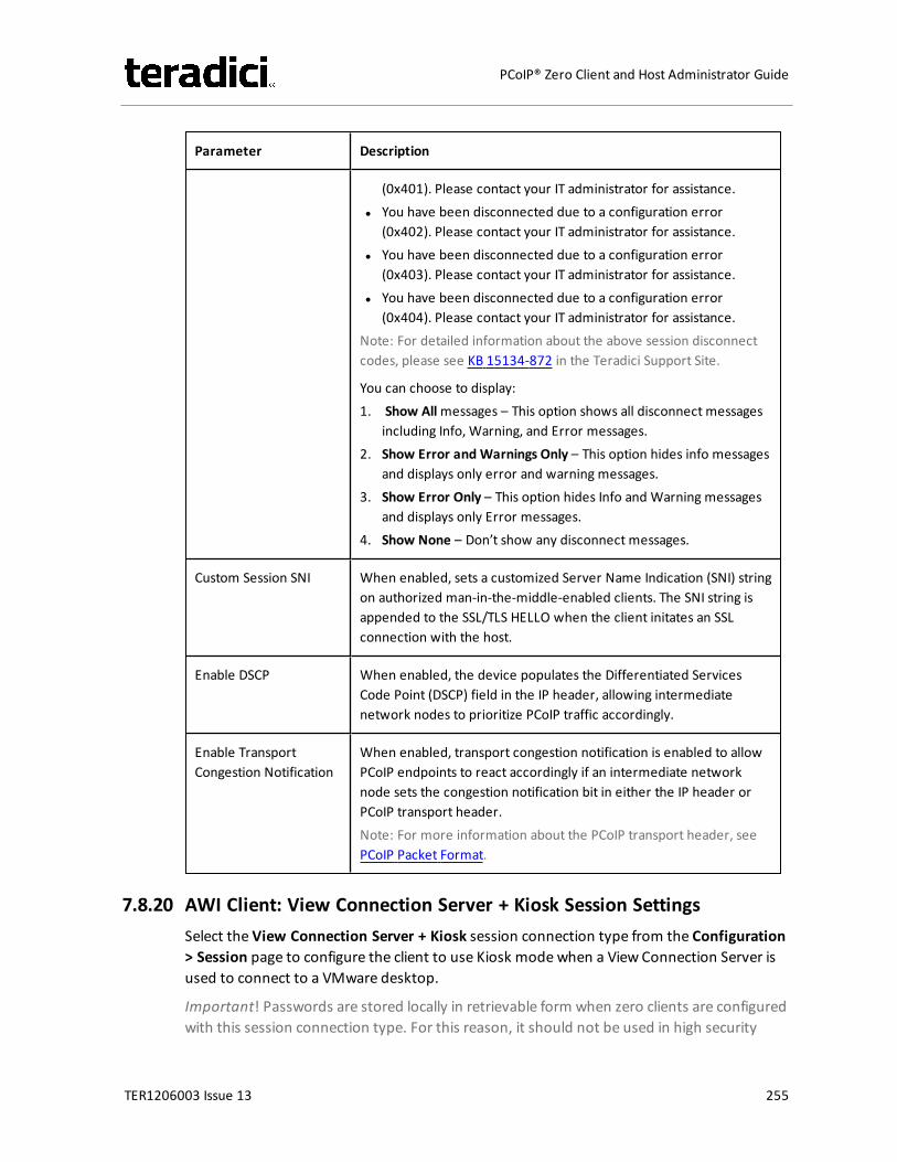
Parameter Description
(0x401). Please contact your IT administrator for assistance.l You have been disconnected due to a configuration error
(0x402). Please contact your IT administrator for assistance.l You have been disconnected due to a configuration error
(0x403). Please contact your IT administrator for assistance.l You have been disconnected due to a configuration error
(0x404). Please contact your IT administrator for assistance.Note: For detailed information about the above session disconnectcodes, please see KB 15134-872 in the Teradici Support Site.
You can choose to display:1. Show Allmessages – This option shows all disconnect messages
including Info, Warning, and Error messages.2. Show Error and Warnings Only – This option hides info messages
and displays only error and warning messages.3. Show Error Only – This option hides Info and Warning messages
and displays only Error messages.4. Show None – Don’t show any disconnect messages.
Custom Session SNI When enabled, sets a customized Server Name Indication (SNI) stringon authorized man-in-the-middle-enabled clients. The SNI string isappended to the SSL/TLS HELLO when the client initates an SSLconnection with the host.
Enable DSCP When enabled, the device populates the Differentiated ServicesCode Point (DSCP) field in the IP header, allowing intermediatenetwork nodes to prioritize PCoIP traffic accordingly.
Enable TransportCongestion Notification
When enabled, transport congestion notification is enabled to allowPCoIP endpoints to react accordingly if an intermediate networknode sets the congestion notification bit in either the IP header orPCoIP transport header.Note: For more information about the PCoIP transport header, seePCoIP Packet Format.
7.8.20 AWI Client: View Connection Server + Kiosk Session SettingsSelect the View Connection Server + Kiosk session connection type from the Configuration> Session page to configure the client to use Kiosk modewhen a View Connection Server isused to connect to a VMware desktop.
Important! Passwords are stored locally in retrievable form when zero clients are configuredwith this session connection type. For this reason, it should not be used in high security
TER1206003 Issue 13 255
PCoIP® Zero Client and Host Administrator Guide
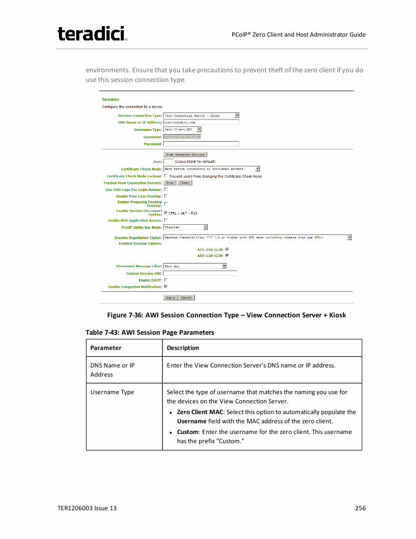
environments. Ensure that you take precautions to prevent theft of the zero client if you douse this session connection type.
Figure 7-36: AWI Session Connection Type – View Connection Server + Kiosk
Table 7-43: AWI Session Page Parameters
Parameter Description
DNS Name or IPAddress
Enter the View Connection Server's DNS name or IP address.
Username Type Select the type of username that matches the naming you use forthe devices on the View Connection Server.l Zero Client MAC: Select this option to automatically populate the
Username field with the MAC address of the zero client.l Custom: Enter the username for the zero client. This username
has the prefix "Custom."
TER1206003 Issue 13 256
PCoIP® Zero Client and Host Administrator Guide
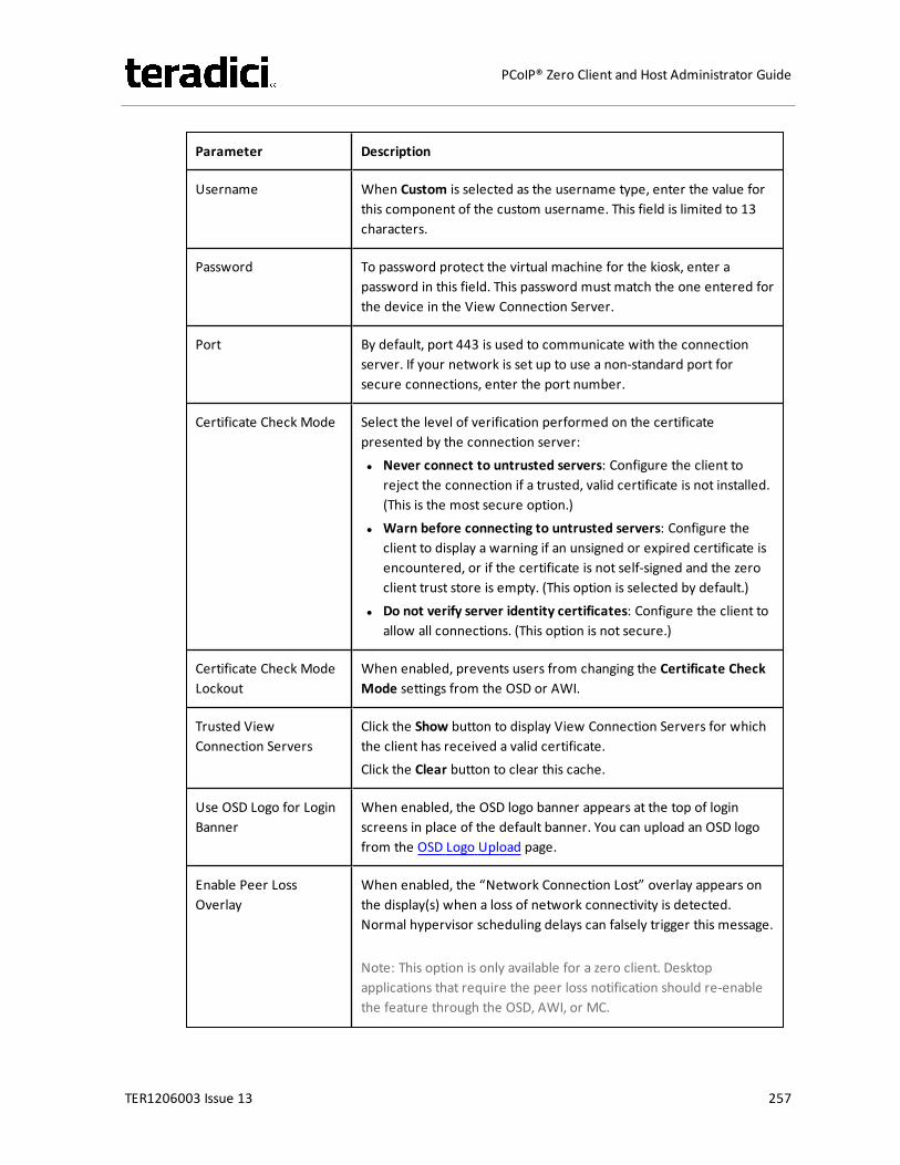
Parameter Description
Username When Custom is selected as the username type, enter the value forthis component of the custom username. This field is limited to 13characters.
Password To password protect the virtual machine for the kiosk, enter apassword in this field. This password must match the one entered forthe device in the View Connection Server.
Port By default, port 443 is used to communicate with the connectionserver. If your network is set up to use a non-standard port forsecure connections, enter the port number.
Certificate Check Mode Select the level of verification performed on the certificatepresented by the connection server:l Never connect to untrusted servers: Configure the client to
reject the connection if a trusted, valid certificate is not installed.(This is the most secure option.)
l Warn before connecting to untrusted servers: Configure theclient to display a warning if an unsigned or expired certificate isencountered, or if the certificate is not self-signed and the zeroclient trust store is empty. (This option is selected by default.)
l Do not verify server identity certificates: Configure the client toallow all connections. (This option is not secure.)
Certificate Check ModeLockout
When enabled, prevents users from changing the Certificate CheckMode settings from the OSD or AWI.
Trusted ViewConnection Servers
Click the Show button to display View Connection Servers for whichthe client has received a valid certificate.Click the Clear button to clear this cache.
Use OSD Logo for LoginBanner
When enabled, the OSD logo banner appears at the top of loginscreens in place of the default banner. You can upload an OSD logofrom the OSD Logo Upload page.
Enable Peer LossOverlay
When enabled, the “Network Connection Lost” overlay appears onthe display(s) when a loss of network connectivity is detected.Normal hypervisor scheduling delays can falsely trigger this message.
Note: This option is only available for a zero client. Desktopapplications that require the peer loss notification should re-enablethe feature through the OSD, AWI, or MC.
TER1206003 Issue 13 257
PCoIP® Zero Client and Host Administrator Guide
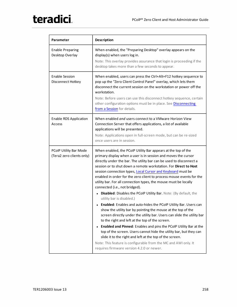
Parameter Description
Enable PreparingDesktop Overlay
When enabled, the "Preparing Desktop" overlay appears on thedisplay(s) when users log in.Note: This overlay provides assurance that login is proceeding if thedesktop takes more than a few seconds to appear.
Enable SessionDisconnect Hotkey
When enabled, users can press the Ctrl+Alt+F12 hotkey sequence topop up the "Zero Client Control Panel" overlay, which lets themdisconnect the current session on the workstation or power off theworkstation.Note: Before users can use this disconnect hotkey sequence, certainother configuration options must be in place. See Disconnectingfrom a Session for details.
Enable RDS ApplicationAccess
When enabled and users connect to a VMware Horizon ViewConnection Server that offers applications, a list of availableapplications will be presented.Note: Applications open in full-screen mode, but can be re-sizedonce users are in session.
PCoIP Utility Bar Mode(Tera2 zero clients only)
When enabled, the PCoIP Utility Bar appears at the top of theprimary display when a user is in session and moves the cursordirectly under the bar. The utility bar can be used to disconnect asession or to shut down a remote workstation. For Direct to Hostsession connection types, Local Cursor and Keyboard must beenabled in order for the zero client to process mouse events for theutility bar. For all connection types, the mouse must be locallyconnected (i.e., not bridged).l Disabled: Disables the PCoIP Utility Bar. Note: (By default, the
utility bar is disabled.)l Enabled: Enables and auto-hides the PCoIP Utility Bar. Users can
show the utility bar by pointing the mouse at the top of thescreen directly under the utility bar. Users can slide the utility barto the right and left at the top of the screen.
l Enabled and Pinned: Enables and pins the PCoIP Utility Bar at thetop of the screen. Users cannot hide the utility bar, but they canslide it to the right and left at the top of the screen.
Note: This feature is configurable from the MC and AWI only. Itrequires firmware version 4.2.0 or newer.
TER1206003 Issue 13 258
PCoIP® Zero Client and Host Administrator Guide

Parameter Description
Session NegotiationCipher
Important: In release 4.8.0, the security cipher features listed beloware supported on Tera2 zero clients only. In order to use a non-SHA-1 cipher, both the client and host endpoints must support it.
Note: For sessions with software hosts, the zero client should beconfigured to use the Maximum Compatibility option.
For Tera2 zero clients:Configure the Transport Layer Security (TLS) cipher to use fornegotiating the TLS session between the PCoIP client and the PCoIPhost.l Maximum Compatibility: TLS 1.0 or higher with RSA keys
including ciphers that use SHA-1: This option provides maximumcompatibility.
l Suite B: TLS 1.2 with Suite B-compliant 192-bit elliptic curveencryption. This option provides a higher level of security.
l Disable SHA-1: TLS 1.2 with RSA keys and strong ciphers usingonly SHA-256 or SHA-384: When selected, only devices runningfirmware 4.8.0 or greater are affected.Note: Currently this option can only be used with AmazonWorkSpaces hosts.
For Tera1 zero clients:Configure the Transport Layer Security (TLS) cipher to use fornegotiating the TLS session between the PCoIP client and the PCoIPhost.l Maximum Compatibility: TLS 1.0 with RSA keys and AES-256 or
AES-128 encryption: This option provides maximumcompatibility.
l Suite B: TLS 1.2 with Suite B-compliant 192-bit elliptic curveencryption. This option provides a higher level of security.
TER1206003 Issue 13 259
PCoIP® Zero Client and Host Administrator Guide

Parameter Description
Enabled Session Ciphers Enable or disable an encryption mode for the device. By default, allencryption modes that pertain to a device are enabled.l AES-128-GCM (Tera1 and Tera2): An encryption method
implemented in first-generation Tera1 and second-generationTera2 processors. This method offers the best performancebetween hardware endpoints for Tera1 devices. AES-128-GCMalso may offer improved performance for Tera2 clients whenconnecting to VMware 4 or newer if there is more than about 7Mbps available on the network.
l AES-256-GCM (Tera2 only): A more secure encryption methodimplemented in second-generation Tera2 processors that offersthe best performance between hardware endpoints. Whenconnecting to VMware 4 or newer, AES-128-GCM isrecommended.
l Salsa20-256-Round12 (Tera1 only): A lighter encryption methodimplemented in firmware that may offer improved performancefor Tera1 clients when connecting to VMware View 4 or newer ifthere is more than about 7 Mbps available on the network.
Note: For more information about connecting to VMware Horizonvirtual desktops, see “Using PCoIP® Zero Clients with VMware ViewUser Guide” (TER0904005) in the Teradici Support DocumentationCenter.
Note: The enabled encryption mode must match between the hostand client for a session to be established. If more than one mode isenabled, the firmware selects the following:
l Host to Tera1 or Tera2 clients: AES-128-GCM or AES-256-GCMfor the PCoIP session.
l VMware View 4.5 and later to Tera1 client: SALSA20-256-Round12 for the PCoIP session.
l VMware View 4.5 and later to Tera2 client: AES-128-GCM for thePCoIP session.
TER1206003 Issue 13 260
PCoIP® Zero Client and Host Administrator Guide

Parameter Description
Disconnect MessageFilter
This field lets you control what type of messages appear when asession is disconnected. There are three categories:Information: User- or administrator-initiated actions affecting thesession:l You have been disconnected because you logged in from
another location or your host was shut down or restarted.l You have been disconnected because an administrator
disconnected you.l You have been disconnected because you logged in from
another location.l You have been disconnected because you disconnected from
your workstation.Warning: System-initiated, but expected actions affecting thesession:l You have been disconnected because your session timed out.Error: Unexpected system-initiated actions causing session to fail:l You have been disconnected.l Unable to connect (0x1001). Please contact your IT
administrator.l Unable to connect (0x1002). Please contact your IT
administrator.l Session closed remotely.l Session closed remotely (unknown cause).l You have been disconnected due to a configuration error
(0x100). Please contact your IT administrator for assistance.l You have been disconnected due to a configuration error
(0x201). Please contact your IT administrator for assistance.l You have been disconnected due to a configuration error
(0x300). Please contact your IT administrator for assistance.l You have been disconnected due to a configuration error
(0x301). Please contact your IT administrator for assistance.l You have been disconnected due to a configuration error
(0x302). Please contact your IT administrator for assistance.l You have been disconnected due to a configuration error
(0x303). Please contact your IT administrator for assistance.l You have been disconnected due to a configuration error
(0x305). Please contact your IT administrator for assistance.l You have been disconnected due to a configuration error
(0x400). Please contact your IT administrator for assistance.l You have been disconnected due to a configuration error
TER1206003 Issue 13 261
PCoIP® Zero Client and Host Administrator Guide
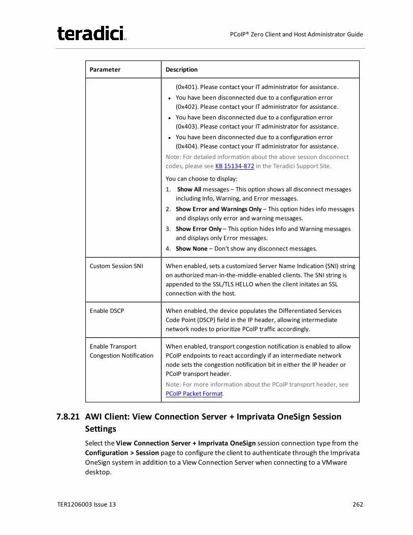
Parameter Description
(0x401). Please contact your IT administrator for assistance.l You have been disconnected due to a configuration error
(0x402). Please contact your IT administrator for assistance.l You have been disconnected due to a configuration error
(0x403). Please contact your IT administrator for assistance.l You have been disconnected due to a configuration error
(0x404). Please contact your IT administrator for assistance.Note: For detailed information about the above session disconnectcodes, please see KB 15134-872 in the Teradici Support Site.
You can choose to display:1. Show Allmessages – This option shows all disconnect messages
including Info, Warning, and Error messages.2. Show Error and Warnings Only – This option hides info messages
and displays only error and warning messages.3. Show Error Only – This option hides Info and Warning messages
and displays only Error messages.4. Show None – Don’t show any disconnect messages.
Custom Session SNI When enabled, sets a customized Server Name Indication (SNI) stringon authorized man-in-the-middle-enabled clients. The SNI string isappended to the SSL/TLS HELLO when the client initates an SSLconnection with the host.
Enable DSCP When enabled, the device populates the Differentiated ServicesCode Point (DSCP) field in the IP header, allowing intermediatenetwork nodes to prioritize PCoIP traffic accordingly.
Enable TransportCongestion Notification
When enabled, transport congestion notification is enabled to allowPCoIP endpoints to react accordingly if an intermediate networknode sets the congestion notification bit in either the IP header orPCoIP transport header.Note: For more information about the PCoIP transport header, seePCoIP Packet Format.
7.8.21 AWI Client: View Connection Server + Imprivata OneSign SessionSettingsSelect the View Connection Server + Imprivata OneSign session connection type from theConfiguration > Session page to configure the client to authenticate through the ImprivataOneSign system in addition to a View Connection Server when connecting to a VMwaredesktop.
TER1206003 Issue 13 262
PCoIP® Zero Client and Host Administrator Guide
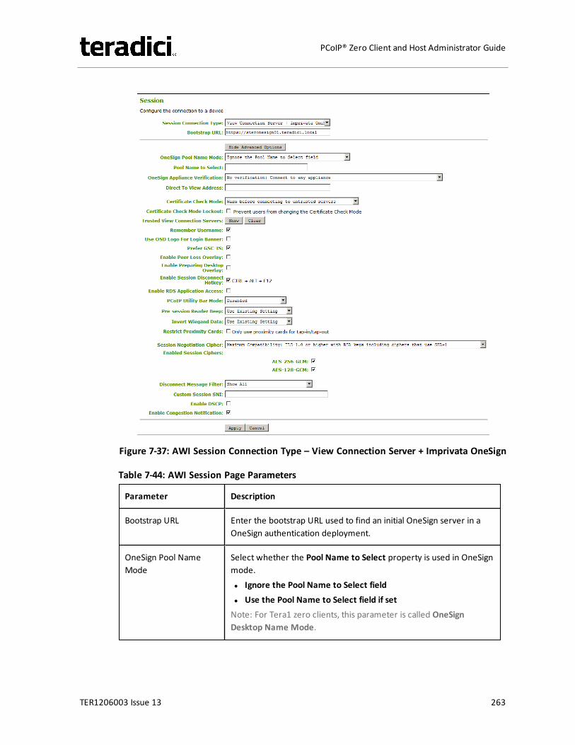
Figure 7-37: AWI Session Connection Type – View Connection Server + Imprivata OneSign
Table 7-44: AWI Session Page Parameters
Parameter Description
Bootstrap URL Enter the bootstrap URL used to find an initial OneSign server in aOneSign authentication deployment.
OneSign Pool NameMode
Select whether the Pool Name to Select property is used in OneSignmode.l Ignore the Pool Name to Select fieldl Use the Pool Name to Select field if setNote: For Tera1 zero clients, this parameter is called OneSignDesktop Name Mode.
TER1206003 Issue 13 263
PCoIP® Zero Client and Host Administrator Guide
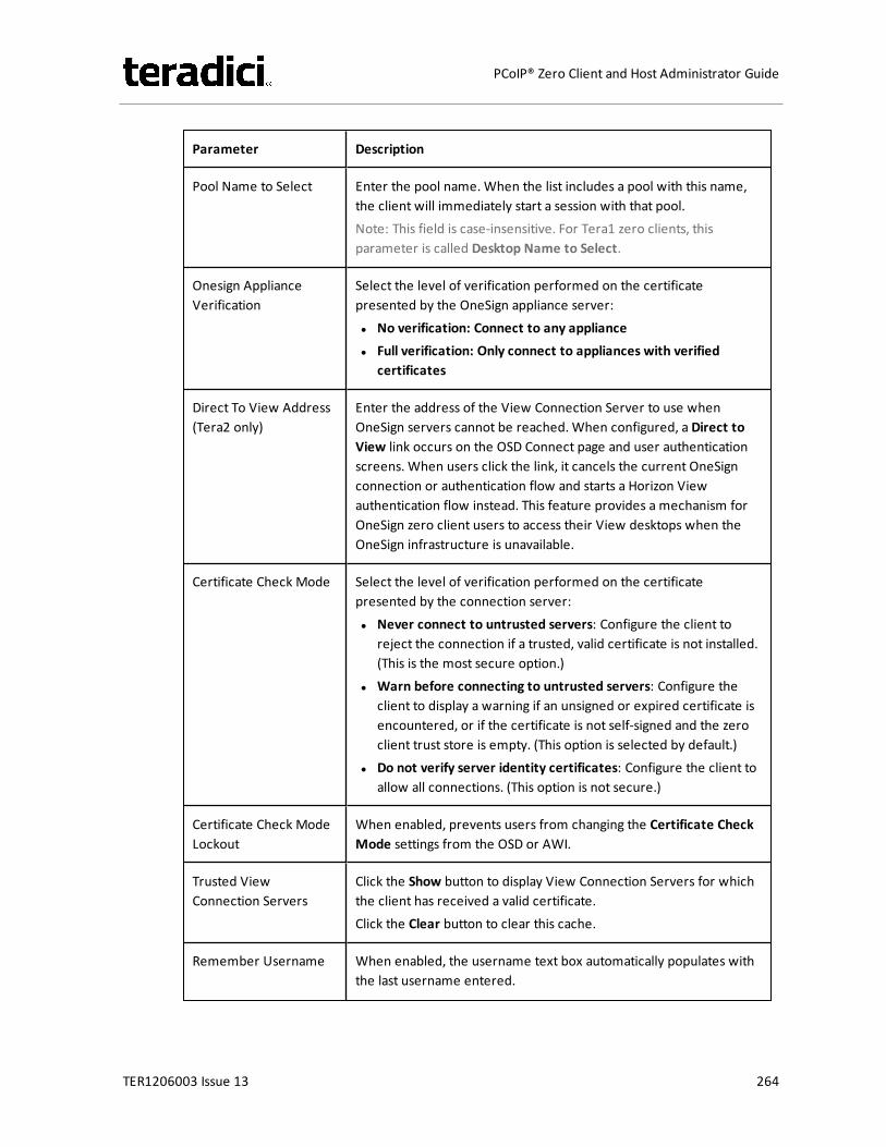
Parameter Description
Pool Name to Select Enter the pool name. When the list includes a pool with this name,the client will immediately start a session with that pool.Note: This field is case-insensitive. For Tera1 zero clients, thisparameter is called Desktop Name to Select.
Onesign ApplianceVerification
Select the level of verification performed on the certificatepresented by the OneSign appliance server:l No verification: Connect to any appliancel Full verification: Only connect to appliances with verified
certificates
Direct To View Address(Tera2 only)
Enter the address of the View Connection Server to use whenOneSign servers cannot be reached. When configured, a Direct toView link occurs on the OSD Connect page and user authenticationscreens. When users click the link, it cancels the current OneSignconnection or authentication flow and starts a Horizon Viewauthentication flow instead. This feature provides a mechanism forOneSign zero client users to access their View desktops when theOneSign infrastructure is unavailable.
Certificate Check Mode Select the level of verification performed on the certificatepresented by the connection server:l Never connect to untrusted servers: Configure the client to
reject the connection if a trusted, valid certificate is not installed.(This is the most secure option.)
l Warn before connecting to untrusted servers: Configure theclient to display a warning if an unsigned or expired certificate isencountered, or if the certificate is not self-signed and the zeroclient trust store is empty. (This option is selected by default.)
l Do not verify server identity certificates: Configure the client toallow all connections. (This option is not secure.)
Certificate Check ModeLockout
When enabled, prevents users from changing the Certificate CheckMode settings from the OSD or AWI.
Trusted ViewConnection Servers
Click the Show button to display View Connection Servers for whichthe client has received a valid certificate.Click the Clear button to clear this cache.
Remember Username When enabled, the username text box automatically populates withthe last username entered.
TER1206003 Issue 13 264
PCoIP® Zero Client and Host Administrator Guide
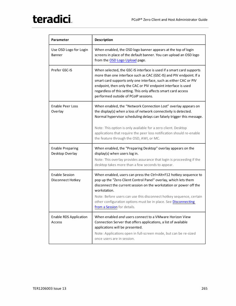
Parameter Description
Use OSD Logo for LoginBanner
When enabled, the OSD logo banner appears at the top of loginscreens in place of the default banner. You can upload an OSD logofrom the OSD Logo Upload page.
Prefer GSC-IS When selected, the GSC-IS interface is used if a smart card supportsmore than one interface such as CAC (GSC-IS) and PIV endpoint. If asmart card supports only one interface, such as either CAC or PIVendpoint, then only the CAC or PIV endpoint interface is usedregardless of this setting. This only affects smart card accessperformed outside of PCoIP sessions.
Enable Peer LossOverlay
When enabled, the “Network Connection Lost” overlay appears onthe display(s) when a loss of network connectivity is detected.Normal hypervisor scheduling delays can falsely trigger this message.
Note: This option is only available for a zero client. Desktopapplications that require the peer loss notification should re-enablethe feature through the OSD, AWI, or MC.
Enable PreparingDesktop Overlay
When enabled, the "Preparing Desktop" overlay appears on thedisplay(s) when users log in.Note: This overlay provides assurance that login is proceeding if thedesktop takes more than a few seconds to appear.
Enable SessionDisconnect Hotkey
When enabled, users can press the Ctrl+Alt+F12 hotkey sequence topop up the "Zero Client Control Panel" overlay, which lets themdisconnect the current session on the workstation or power off theworkstation.Note: Before users can use this disconnect hotkey sequence, certainother configuration options must be in place. See Disconnectingfrom a Session for details.
Enable RDS ApplicationAccess
When enabled and users connect to a VMware Horizon ViewConnection Server that offers applications, a list of availableapplications will be presented.Note: Applications open in full-screen mode, but can be re-sizedonce users are in session.
TER1206003 Issue 13 265
PCoIP® Zero Client and Host Administrator Guide
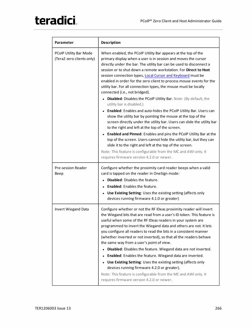
Parameter Description
PCoIP Utility Bar Mode(Tera2 zero clients only)
When enabled, the PCoIP Utility Bar appears at the top of theprimary display when a user is in session and moves the cursordirectly under the bar. The utility bar can be used to disconnect asession or to shut down a remote workstation. For Direct to Hostsession connection types, Local Cursor and Keyboard must beenabled in order for the zero client to process mouse events for theutility bar. For all connection types, the mouse must be locallyconnected (i.e., not bridged).l Disabled: Disables the PCoIP Utility Bar. Note: (By default, the
utility bar is disabled.)l Enabled: Enables and auto-hides the PCoIP Utility Bar. Users can
show the utility bar by pointing the mouse at the top of thescreen directly under the utility bar. Users can slide the utility barto the right and left at the top of the screen.
l Enabled and Pinned: Enables and pins the PCoIP Utility Bar at thetop of the screen. Users cannot hide the utility bar, but they canslide it to the right and left at the top of the screen.
Note: This feature is configurable from the MC and AWI only. Itrequires firmware version 4.2.0 or newer.
Pre-session ReaderBeep
Configure whether the proximity card reader beeps when a validcard is tapped on the reader in OneSign mode:l Disabled: Disables the feature.l Enabled: Enables the feature.l Use Existing Setting: Uses the existing setting (affects only
devices running firmware 4.1.0 or greater)
Invert Wiegand Data Configure whether or not the RF IDeas proximity reader will invertthe Wiegand bits that are read from a user's ID token. This feature isuseful when some of the RF IDeas readers in your system areprogrammed to invert the Wiegand data and others are not. It letsyou configure all readers to read the bits in a consistent manner(whether inverted or not inverted), so that all the readers behavethe same way from a user's point of view.l Disabled: Disables the feature. Wiegand data are not inverted.l Enabled: Enables the feature. Wiegand data are inverted.l Use Existing Setting: Uses the existing setting (affects only
devices running firmware 4.2.0 or greater).Note: This feature is configurable from the MC and AWI only. Itrequires firmware version 4.2.0 or newer.
TER1206003 Issue 13 266
PCoIP® Zero Client and Host Administrator Guide
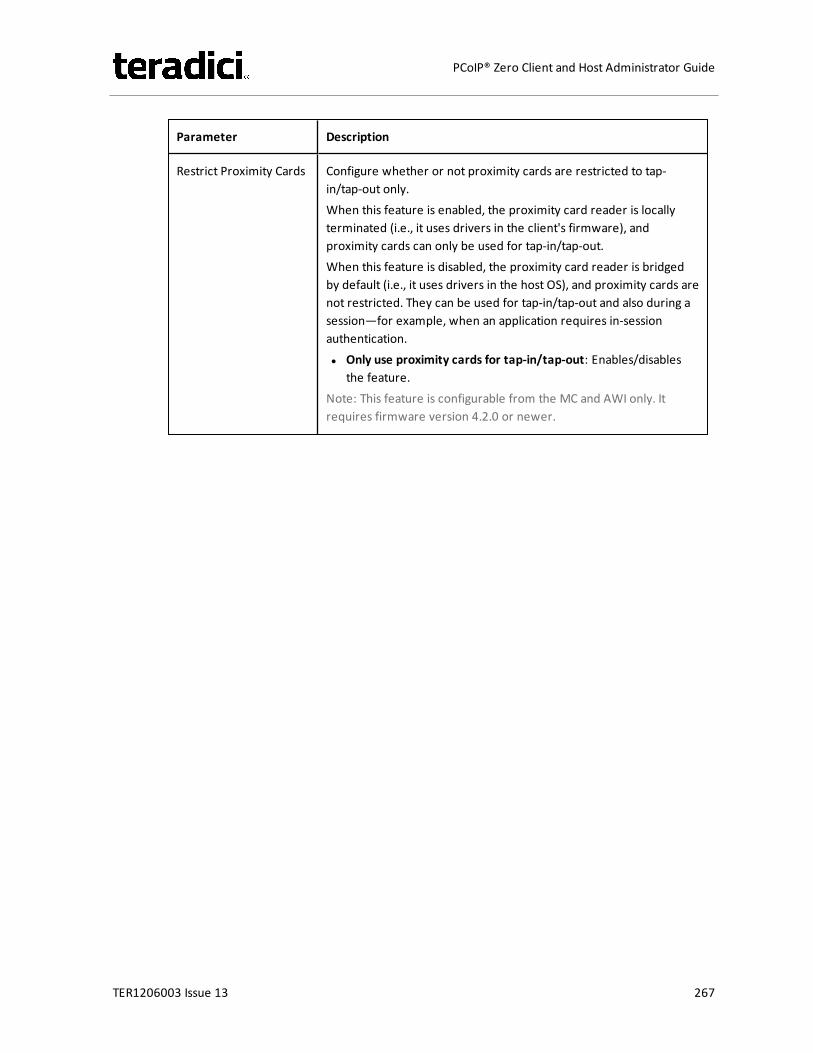
Parameter Description
Restrict Proximity Cards Configure whether or not proximity cards are restricted to tap-in/tap-out only.When this feature is enabled, the proximity card reader is locallyterminated (i.e., it uses drivers in the client's firmware), andproximity cards can only be used for tap-in/tap-out.When this feature is disabled, the proximity card reader is bridgedby default (i.e., it uses drivers in the host OS), and proximity cards arenot restricted. They can be used for tap-in/tap-out and also during asession—for example, when an application requires in-sessionauthentication.l Only use proximity cards for tap-in/tap-out: Enables/disables
the feature.Note: This feature is configurable from the MC and AWI only. Itrequires firmware version 4.2.0 or newer.
TER1206003 Issue 13 267
PCoIP® Zero Client and Host Administrator Guide

Parameter Description
Session NegotiationCipher
Important: In release 4.8.0, the security cipher features listed beloware supported on Tera2 zero clients only. In order to use a non-SHA-1 cipher, both the client and host endpoints must support it.
Note: For sessions with software hosts, the zero client should beconfigured to use the Maximum Compatibility option.
For Tera2 zero clients:Configure the Transport Layer Security (TLS) cipher to use fornegotiating the TLS session between the PCoIP client and the PCoIPhost.l Maximum Compatibility: TLS 1.0 or higher with RSA keys
including ciphers that use SHA-1: This option provides maximumcompatibility.
l Suite B: TLS 1.2 with Suite B-compliant 192-bit elliptic curveencryption. This option provides a higher level of security.
l Disable SHA-1: TLS 1.2 with RSA keys and strong ciphers usingonly SHA-256 or SHA-384: When selected, only devices runningfirmware 4.8.0 or greater are affected.Note: Currently this option can only be used with AmazonWorkSpaces hosts.
For Tera1 zero clients:Configure the Transport Layer Security (TLS) cipher to use fornegotiating the TLS session between the PCoIP client and the PCoIPhost.l Maximum Compatibility: TLS 1.0 with RSA keys and AES-256 or
AES-128 encryption: This option provides maximumcompatibility.
l Suite B: TLS 1.2 with Suite B-compliant 192-bit elliptic curveencryption. This option provides a higher level of security.
TER1206003 Issue 13 268
PCoIP® Zero Client and Host Administrator Guide

Parameter Description
Enabled Session Ciphers Enable or disable an encryption mode for the device. By default, allencryption modes that pertain to a device are enabled.l AES-128-GCM (Tera1 and Tera2): An encryption method
implemented in first-generation Tera1 and second-generationTera2 processors. This method offers the best performancebetween hardware endpoints for Tera1 devices. AES-128-GCMalso may offer improved performance for Tera2 clients whenconnecting to VMware 4 or newer if there is more than about 7Mbps available on the network.
l AES-256-GCM (Tera2 only): A more secure encryption methodimplemented in second-generation Tera2 processors that offersthe best performance between hardware endpoints. Whenconnecting to VMware 4 or newer, AES-128-GCM isrecommended.
l Salsa20-256-Round12 (Tera1 only): A lighter encryption methodimplemented in firmware that may offer improved performancefor Tera1 clients when connecting to VMware View 4 or newer ifthere is more than about 7 Mbps available on the network.
Note: For more information about connecting to VMware Horizonvirtual desktops, see “Using PCoIP® Zero Clients with VMware ViewUser Guide” (TER0904005) in the Teradici Support DocumentationCenter.
Note: The enabled encryption mode must match between the hostand client for a session to be established. If more than one mode isenabled, the firmware selects the following:
l Host to Tera1 or Tera2 clients: AES-128-GCM or AES-256-GCMfor the PCoIP session.
l VMware View 4.5 and later to Tera1 client: SALSA20-256-Round12 for the PCoIP session.
l VMware View 4.5 and later to Tera2 client: AES-128-GCM for thePCoIP session.
TER1206003 Issue 13 269
PCoIP® Zero Client and Host Administrator Guide

Parameter Description
Disconnect MessageFilter
This field lets you control what type of messages appear when asession is disconnected. There are three categories:Information: User- or administrator-initiated actions affecting thesession:l You have been disconnected because you logged in from
another location or your host was shut down or restarted.l You have been disconnected because an administrator
disconnected you.l You have been disconnected because you logged in from
another location.l You have been disconnected because you disconnected from
your workstation.Warning: System-initiated, but expected actions affecting thesession:l You have been disconnected because your session timed out.Error: Unexpected system-initiated actions causing session to fail:l You have been disconnected.l Unable to connect (0x1001). Please contact your IT
administrator.l Unable to connect (0x1002). Please contact your IT
administrator.l Session closed remotely.l Session closed remotely (unknown cause).l You have been disconnected due to a configuration error
(0x100). Please contact your IT administrator for assistance.l You have been disconnected due to a configuration error
(0x201). Please contact your IT administrator for assistance.l You have been disconnected due to a configuration error
(0x300). Please contact your IT administrator for assistance.l You have been disconnected due to a configuration error
(0x301). Please contact your IT administrator for assistance.l You have been disconnected due to a configuration error
(0x302). Please contact your IT administrator for assistance.l You have been disconnected due to a configuration error
(0x303). Please contact your IT administrator for assistance.l You have been disconnected due to a configuration error
(0x305). Please contact your IT administrator for assistance.l You have been disconnected due to a configuration error
(0x400). Please contact your IT administrator for assistance.l You have been disconnected due to a configuration error
TER1206003 Issue 13 270
PCoIP® Zero Client and Host Administrator Guide
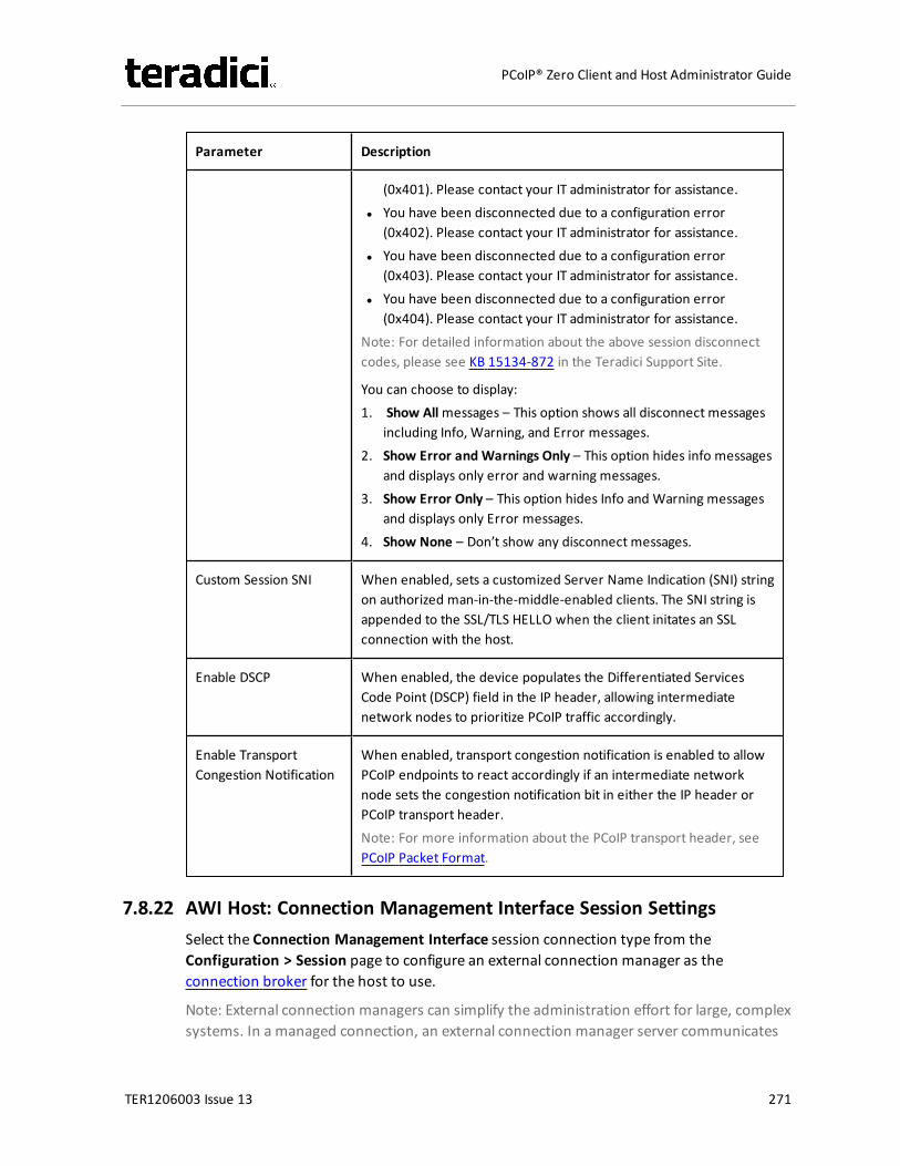
Parameter Description
(0x401). Please contact your IT administrator for assistance.l You have been disconnected due to a configuration error
(0x402). Please contact your IT administrator for assistance.l You have been disconnected due to a configuration error
(0x403). Please contact your IT administrator for assistance.l You have been disconnected due to a configuration error
(0x404). Please contact your IT administrator for assistance.Note: For detailed information about the above session disconnectcodes, please see KB 15134-872 in the Teradici Support Site.
You can choose to display:1. Show Allmessages – This option shows all disconnect messages
including Info, Warning, and Error messages.2. Show Error and Warnings Only – This option hides info messages
and displays only error and warning messages.3. Show Error Only – This option hides Info and Warning messages
and displays only Error messages.4. Show None – Don’t show any disconnect messages.
Custom Session SNI When enabled, sets a customized Server Name Indication (SNI) stringon authorized man-in-the-middle-enabled clients. The SNI string isappended to the SSL/TLS HELLO when the client initates an SSLconnection with the host.
Enable DSCP When enabled, the device populates the Differentiated ServicesCode Point (DSCP) field in the IP header, allowing intermediatenetwork nodes to prioritize PCoIP traffic accordingly.
Enable TransportCongestion Notification
When enabled, transport congestion notification is enabled to allowPCoIP endpoints to react accordingly if an intermediate networknode sets the congestion notification bit in either the IP header orPCoIP transport header.Note: For more information about the PCoIP transport header, seePCoIP Packet Format.
7.8.22 AWI Host: Connection Management Interface Session SettingsSelect the Connection Management Interface session connection type from theConfiguration > Session page to configure an external connection manager as theconnection broker for the host to use.
Note: External connection managers can simplify the administration effort for large, complexsystems. In a managed connection, an external connection manager server communicates
TER1206003 Issue 13 271
PCoIP® Zero Client and Host Administrator Guide
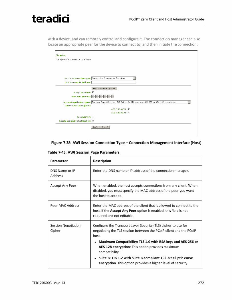
with a device, and can remotely control and configure it. The connection manager can alsolocate an appropriate peer for the device to connect to, and then initiate the connection.
Figure 7-38: AWI Session Connection Type – Connection Management Interface (Host)
Table 7-45: AWI Session Page Parameters
Parameter Description
DNS Name or IPAddress
Enter the DNS name or IP address of the connection manager.
Accept Any Peer When enabled, the host accepts connections from any client. Whendisabled, you must specify the MAC address of the peer you wantthe host to accept.
Peer MAC Address Enter the MAC address of the client that is allowed to connect to thehost. If the Accept Any Peer option is enabled, this field is notrequired and not editable.
Session NegotiationCipher
Configure the Transport Layer Security (TLS) cipher to use fornegotiating the TLS session between the PCoIP client and the PCoIPhost.l Maximum Compatibility: TLS 1.0 with RSA keys and AES-256 or
AES-128 encryption: This option provides maximumcompatibility.
l Suite B: TLS 1.2 with Suite B-compliant 192-bit elliptic curveencryption. This option provides a higher level of security.
TER1206003 Issue 13 272
PCoIP® Zero Client and Host Administrator Guide
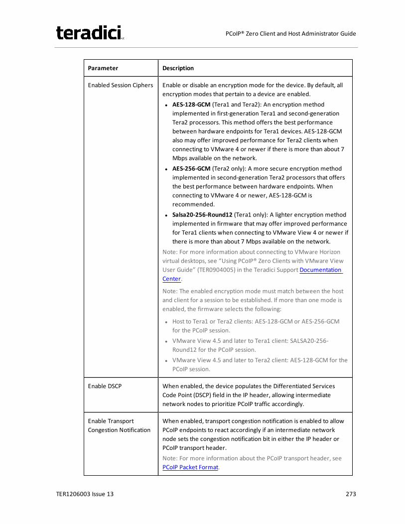
Parameter Description
Enabled Session Ciphers Enable or disable an encryption mode for the device. By default, allencryption modes that pertain to a device are enabled.l AES-128-GCM (Tera1 and Tera2): An encryption method
implemented in first-generation Tera1 and second-generationTera2 processors. This method offers the best performancebetween hardware endpoints for Tera1 devices. AES-128-GCMalso may offer improved performance for Tera2 clients whenconnecting to VMware 4 or newer if there is more than about 7Mbps available on the network.
l AES-256-GCM (Tera2 only): A more secure encryption methodimplemented in second-generation Tera2 processors that offersthe best performance between hardware endpoints. Whenconnecting to VMware 4 or newer, AES-128-GCM isrecommended.
l Salsa20-256-Round12 (Tera1 only): A lighter encryption methodimplemented in firmware that may offer improved performancefor Tera1 clients when connecting to VMware View 4 or newer ifthere is more than about 7 Mbps available on the network.
Note: For more information about connecting to VMware Horizonvirtual desktops, see “Using PCoIP® Zero Clients with VMware ViewUser Guide” (TER0904005) in the Teradici Support DocumentationCenter.
Note: The enabled encryption mode must match between the hostand client for a session to be established. If more than one mode isenabled, the firmware selects the following:
l Host to Tera1 or Tera2 clients: AES-128-GCM or AES-256-GCMfor the PCoIP session.
l VMware View 4.5 and later to Tera1 client: SALSA20-256-Round12 for the PCoIP session.
l VMware View 4.5 and later to Tera2 client: AES-128-GCM for thePCoIP session.
Enable DSCP When enabled, the device populates the Differentiated ServicesCode Point (DSCP) field in the IP header, allowing intermediatenetwork nodes to prioritize PCoIP traffic accordingly.
Enable TransportCongestion Notification
When enabled, transport congestion notification is enabled to allowPCoIP endpoints to react accordingly if an intermediate networknode sets the congestion notification bit in either the IP header orPCoIP transport header.Note: For more information about the PCoIP transport header, seePCoIP Packet Format.
TER1206003 Issue 13 273
PCoIP® Zero Client and Host Administrator Guide
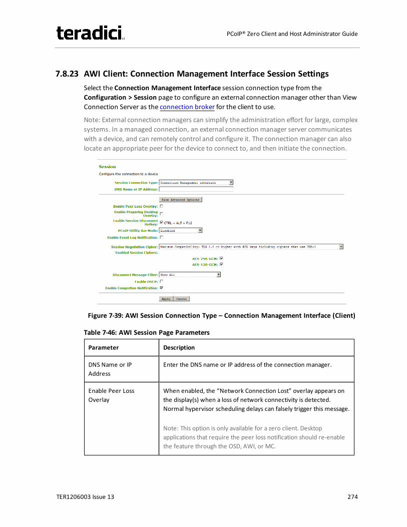
7.8.23 AWI Client: Connection Management Interface Session SettingsSelect the Connection Management Interface session connection type from theConfiguration > Session page to configure an external connection manager other than ViewConnection Server as the connection broker for the client to use.
Note: External connection managers can simplify the administration effort for large, complexsystems. In a managed connection, an external connection manager server communicateswith a device, and can remotely control and configure it. The connection manager can alsolocate an appropriate peer for the device to connect to, and then initiate the connection.
Figure 7-39: AWI Session Connection Type – Connection Management Interface (Client)
Table 7-46: AWI Session Page Parameters
Parameter Description
DNS Name or IPAddress
Enter the DNS name or IP address of the connection manager.
Enable Peer LossOverlay
When enabled, the “Network Connection Lost” overlay appears onthe display(s) when a loss of network connectivity is detected.Normal hypervisor scheduling delays can falsely trigger this message.
Note: This option is only available for a zero client. Desktopapplications that require the peer loss notification should re-enablethe feature through the OSD, AWI, or MC.
TER1206003 Issue 13 274
PCoIP® Zero Client and Host Administrator Guide
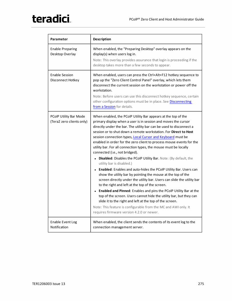
Parameter Description
Enable PreparingDesktop Overlay
When enabled, the "Preparing Desktop" overlay appears on thedisplay(s) when users log in.Note: This overlay provides assurance that login is proceeding if thedesktop takes more than a few seconds to appear.
Enable SessionDisconnect Hotkey
When enabled, users can press the Ctrl+Alt+F12 hotkey sequence topop up the "Zero Client Control Panel" overlay, which lets themdisconnect the current session on the workstation or power off theworkstation.Note: Before users can use this disconnect hotkey sequence, certainother configuration options must be in place. See Disconnectingfrom a Session for details.
PCoIP Utility Bar Mode(Tera2 zero clients only)
When enabled, the PCoIP Utility Bar appears at the top of theprimary display when a user is in session and moves the cursordirectly under the bar. The utility bar can be used to disconnect asession or to shut down a remote workstation. For Direct to Hostsession connection types, Local Cursor and Keyboard must beenabled in order for the zero client to process mouse events for theutility bar. For all connection types, the mouse must be locallyconnected (i.e., not bridged).l Disabled: Disables the PCoIP Utility Bar. Note: (By default, the
utility bar is disabled.)l Enabled: Enables and auto-hides the PCoIP Utility Bar. Users can
show the utility bar by pointing the mouse at the top of thescreen directly under the utility bar. Users can slide the utility barto the right and left at the top of the screen.
l Enabled and Pinned: Enables and pins the PCoIP Utility Bar at thetop of the screen. Users cannot hide the utility bar, but they canslide it to the right and left at the top of the screen.
Note: This feature is configurable from the MC and AWI only. Itrequires firmware version 4.2.0 or newer.
Enable Event LogNotification
When enabled, the client sends the contents of its event log to theconnection management server.
TER1206003 Issue 13 275
PCoIP® Zero Client and Host Administrator Guide

Parameter Description
Session NegotiationCipher
Important: In release 4.8.0, the security cipher features listed beloware supported on Tera2 zero clients only. In order to use a non-SHA-1 cipher, both the client and host endpoints must support it.
Note: For sessions with software hosts, the zero client should beconfigured to use the Maximum Compatibility option.
For Tera2 zero clients:Configure the Transport Layer Security (TLS) cipher to use fornegotiating the TLS session between the PCoIP client and the PCoIPhost.l Maximum Compatibility: TLS 1.0 or higher with RSA keys
including ciphers that use SHA-1: This option provides maximumcompatibility.
l Suite B: TLS 1.2 with Suite B-compliant 192-bit elliptic curveencryption. This option provides a higher level of security.
l Disable SHA-1: TLS 1.2 with RSA keys and strong ciphers usingonly SHA-256 or SHA-384: When selected, only devices runningfirmware 4.8.0 or greater are affected.Note: Currently this option can only be used with AmazonWorkSpaces hosts.
For Tera1 zero clients:Configure the Transport Layer Security (TLS) cipher to use fornegotiating the TLS session between the PCoIP client and the PCoIPhost.l Maximum Compatibility: TLS 1.0 with RSA keys and AES-256 or
AES-128 encryption: This option provides maximumcompatibility.
l Suite B: TLS 1.2 with Suite B-compliant 192-bit elliptic curveencryption. This option provides a higher level of security.
TER1206003 Issue 13 276
PCoIP® Zero Client and Host Administrator Guide

Parameter Description
Enabled Session Ciphers Enable or disable an encryption mode for the device. By default, allencryption modes that pertain to a device are enabled.l AES-128-GCM (Tera1 and Tera2): An encryption method
implemented in first-generation Tera1 and second-generationTera2 processors. This method offers the best performancebetween hardware endpoints for Tera1 devices. AES-128-GCMalso may offer improved performance for Tera2 clients whenconnecting to VMware 4 or newer if there is more than about 7Mbps available on the network.
l AES-256-GCM (Tera2 only): A more secure encryption methodimplemented in second-generation Tera2 processors that offersthe best performance between hardware endpoints. Whenconnecting to VMware 4 or newer, AES-128-GCM isrecommended.
l Salsa20-256-Round12 (Tera1 only): A lighter encryption methodimplemented in firmware that may offer improved performancefor Tera1 clients when connecting to VMware View 4 or newer ifthere is more than about 7 Mbps available on the network.
Note: For more information about connecting to VMware Horizonvirtual desktops, see “Using PCoIP® Zero Clients with VMware ViewUser Guide” (TER0904005) in the Teradici Support DocumentationCenter.
Note: The enabled encryption mode must match between the hostand client for a session to be established. If more than one mode isenabled, the firmware selects the following:
l Host to Tera1 or Tera2 clients: AES-128-GCM or AES-256-GCMfor the PCoIP session.
l VMware View 4.5 and later to Tera1 client: SALSA20-256-Round12 for the PCoIP session.
l VMware View 4.5 and later to Tera2 client: AES-128-GCM for thePCoIP session.
TER1206003 Issue 13 277
PCoIP® Zero Client and Host Administrator Guide

Parameter Description
Disconnect MessageFilter
This field lets you control what type of messages appear when asession is disconnected. There are three categories:Information: User- or administrator-initiated actions affecting thesession:l You have been disconnected because you logged in from
another location or your host was shut down or restarted.l You have been disconnected because an administrator
disconnected you.l You have been disconnected because you logged in from
another location.l You have been disconnected because you disconnected from
your workstation.Warning: System-initiated, but expected actions affecting thesession:l You have been disconnected because your session timed out.Error: Unexpected system-initiated actions causing session to fail:l You have been disconnected.l Unable to connect (0x1001). Please contact your IT
administrator.l Unable to connect (0x1002). Please contact your IT
administrator.l Session closed remotely.l Session closed remotely (unknown cause).l You have been disconnected due to a configuration error
(0x100). Please contact your IT administrator for assistance.l You have been disconnected due to a configuration error
(0x201). Please contact your IT administrator for assistance.l You have been disconnected due to a configuration error
(0x300). Please contact your IT administrator for assistance.l You have been disconnected due to a configuration error
(0x301). Please contact your IT administrator for assistance.l You have been disconnected due to a configuration error
(0x302). Please contact your IT administrator for assistance.l You have been disconnected due to a configuration error
(0x303). Please contact your IT administrator for assistance.l You have been disconnected due to a configuration error
(0x305). Please contact your IT administrator for assistance.l You have been disconnected due to a configuration error
(0x400). Please contact your IT administrator for assistance.l You have been disconnected due to a configuration error
TER1206003 Issue 13 278
PCoIP® Zero Client and Host Administrator Guide
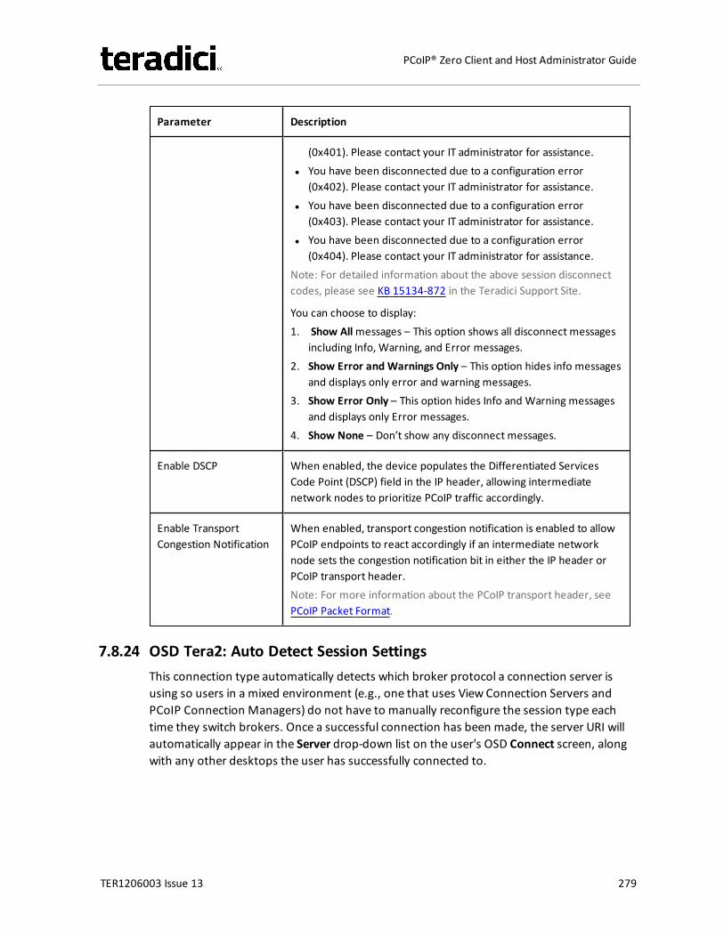
Parameter Description
(0x401). Please contact your IT administrator for assistance.l You have been disconnected due to a configuration error
(0x402). Please contact your IT administrator for assistance.l You have been disconnected due to a configuration error
(0x403). Please contact your IT administrator for assistance.l You have been disconnected due to a configuration error
(0x404). Please contact your IT administrator for assistance.Note: For detailed information about the above session disconnectcodes, please see KB 15134-872 in the Teradici Support Site.
You can choose to display:1. Show Allmessages – This option shows all disconnect messages
including Info, Warning, and Error messages.2. Show Error and Warnings Only – This option hides info messages
and displays only error and warning messages.3. Show Error Only – This option hides Info and Warning messages
and displays only Error messages.4. Show None – Don’t show any disconnect messages.
Enable DSCP When enabled, the device populates the Differentiated ServicesCode Point (DSCP) field in the IP header, allowing intermediatenetwork nodes to prioritize PCoIP traffic accordingly.
Enable TransportCongestion Notification
When enabled, transport congestion notification is enabled to allowPCoIP endpoints to react accordingly if an intermediate networknode sets the congestion notification bit in either the IP header orPCoIP transport header.Note: For more information about the PCoIP transport header, seePCoIP Packet Format.
7.8.24 OSD Tera2: Auto Detect Session SettingsThis connection type automatically detects which broker protocol a connection server isusing so users in a mixed environment (e.g., one that uses View Connection Servers andPCoIP Connection Managers) do not have to manually reconfigure the session type eachtime they switch brokers. Once a successful connection has been made, the server URI willautomatically appear in the Server drop-down list on the user's OSD Connect screen, alongwith any other desktops the user has successfully connected to.
TER1206003 Issue 13 279
PCoIP® Zero Client and Host Administrator Guide
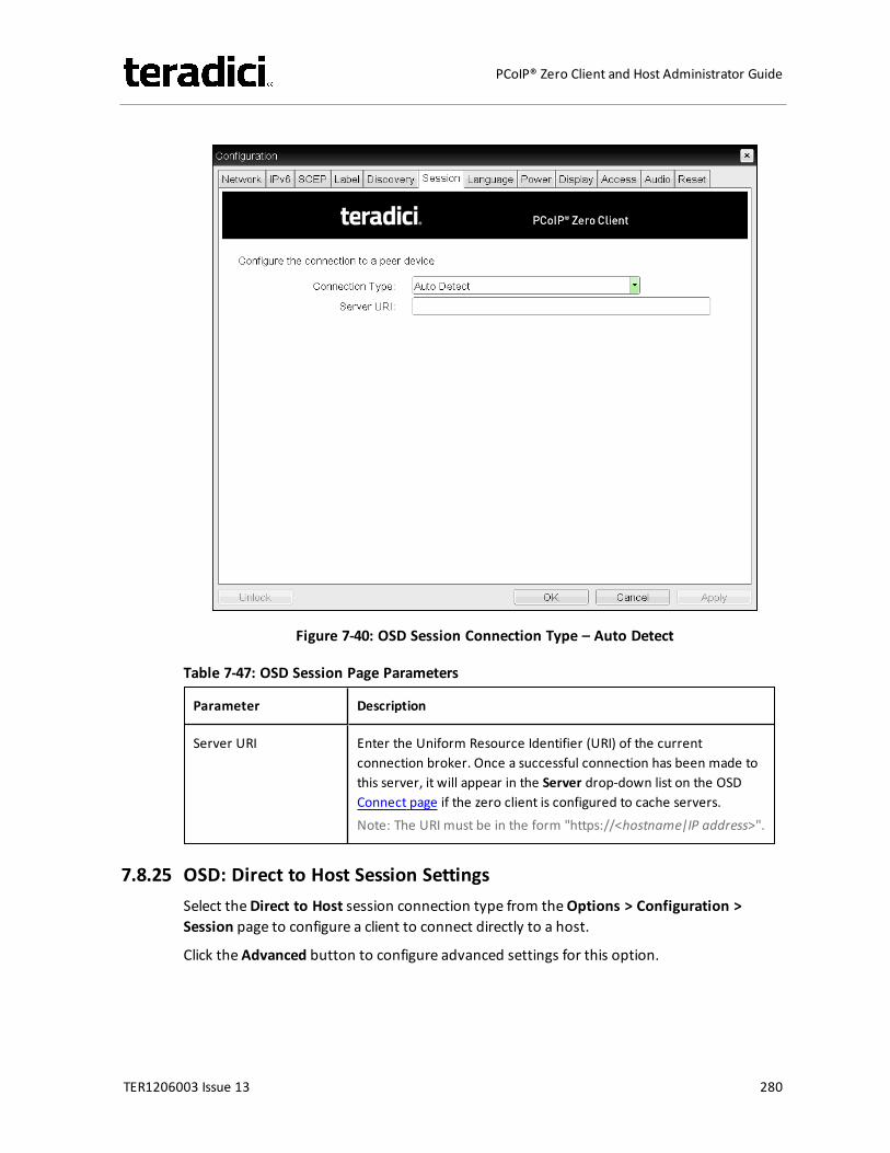
Figure 7-40: OSD Session Connection Type – Auto Detect
Table 7-47: OSD Session Page Parameters
Parameter Description
Server URI Enter the Uniform Resource Identifier (URI) of the currentconnection broker. Once a successful connection has been made tothis server, it will appear in the Server drop-down list on the OSDConnect page if the zero client is configured to cache servers.Note: The URI must be in the form "https://<hostname|IP address>".
7.8.25 OSD: Direct to Host Session SettingsSelect theDirect to Host session connection type from theOptions > Configuration >Session page to configure a client to connect directly to a host.
Click the Advanced button to configure advanced settings for this option.
TER1206003 Issue 13 280
PCoIP® Zero Client and Host Administrator Guide
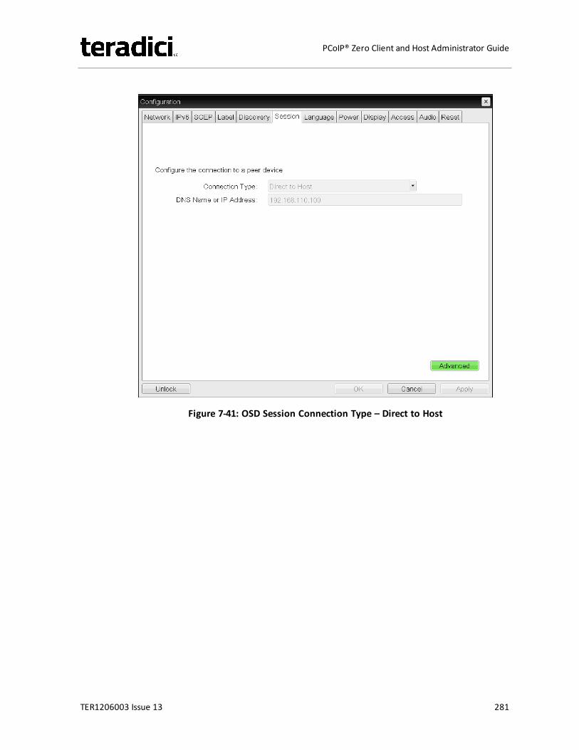
Figure 7-41: OSD Session Connection Type – Direct to Host
TER1206003 Issue 13 281
PCoIP® Zero Client and Host Administrator Guide
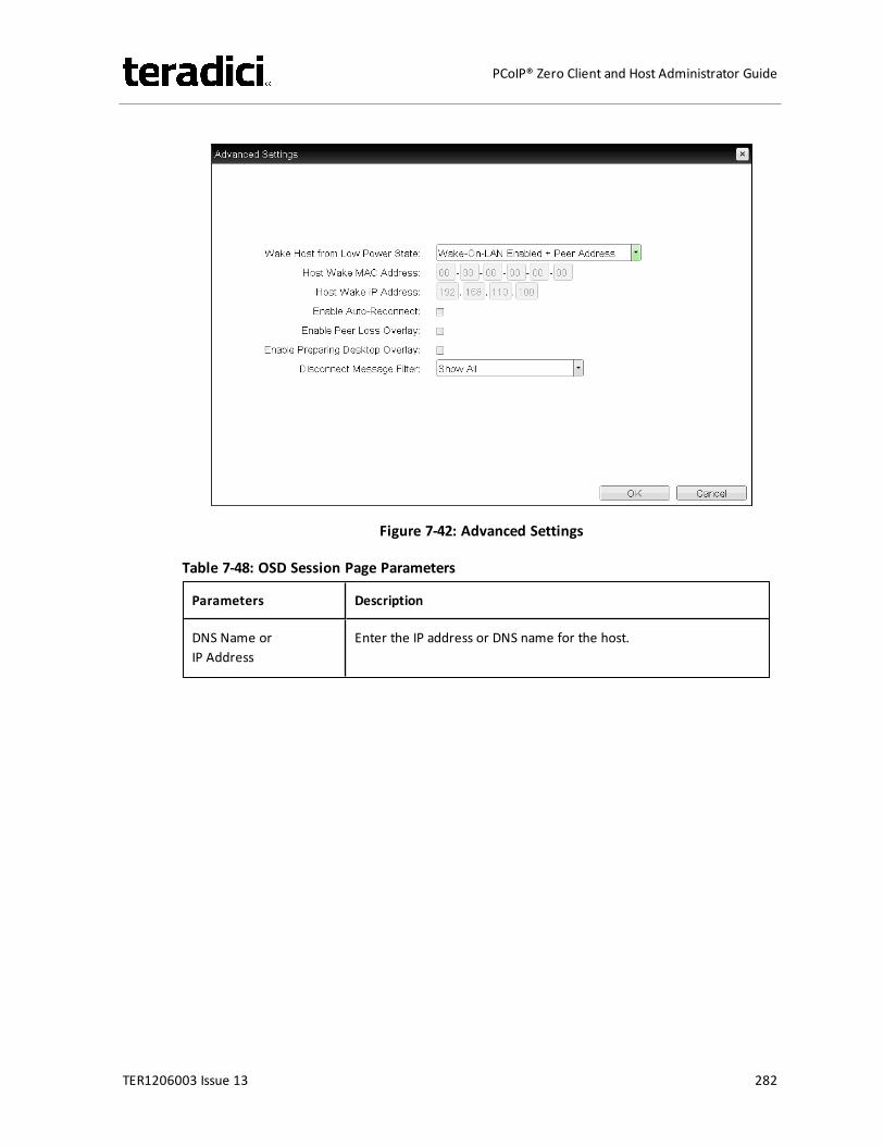
Figure 7-42: Advanced Settings
Table 7-48: OSD Session Page Parameters
Parameters Description
DNS Name orIP Address
Enter the IP address or DNS name for the host.
TER1206003 Issue 13 282
PCoIP® Zero Client and Host Administrator Guide
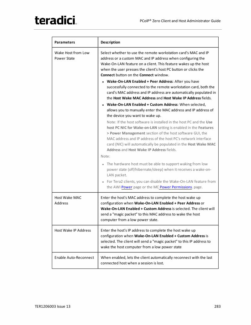
Parameters Description
Wake Host from LowPower State
Select whether to use the remote workstation card's MAC and IPaddress or a custom MAC and IP address when configuring theWake-On-LAN feature on a client. This feature wakes up the hostwhen the user presses the client's host PC button or clicks theConnect button on the Connect window.l Wake-On-LAN Enabled + Peer Address: After you have
successfully connected to the remote workstation card, both thecard's MAC address and IP address are automatically populated inthe Host Wake MAC Address and Host Wake IP Address fields.
l Wake-On-LAN Enabled + Custom Address: When selected,allows you to manually enter the MAC address and IP address ofthe device you want to wake up.Note: If the host software is installed in the host PC and the Usehost PC NIC for Wake-on-LAN setting is enabled in the Features> Power Management section of the host software GUI, theMAC address and IP address of the host PC's network interfacecard (NIC) will automatically be populated in the Host Wake MACAddress and Host Wake IP Address fields.
Note:
l The hardware host must be able to support waking from lowpower state (off/hibernate/sleep) when it receives a wake-on-LAN packet.
l For Tera2 clients, you can disable the Wake-On-LAN feature fromthe AWI Power page or the MC Power Permissions. page.
HostWake MACAddress
Enter the host's MAC address to complete the host wake upconfiguration whenWake-On-LAN Enabled + Peer Address orWake-On-LAN Enabled + Custom Address is selected. The client willsend a "magic packet" to this MAC address to wake the hostcomputer from a low power state.
HostWake IP Address Enter the host's IP address to complete the host wake upconfiguration whenWake-On-LAN Enabled + Custom Address isselected. The client will send a "magic packet" to this IP address towake the host computer from a low power state
Enable Auto-Reconnect When enabled, lets the client automatically reconnect with the lastconnected host when a session is lost.
TER1206003 Issue 13 283
PCoIP® Zero Client and Host Administrator Guide
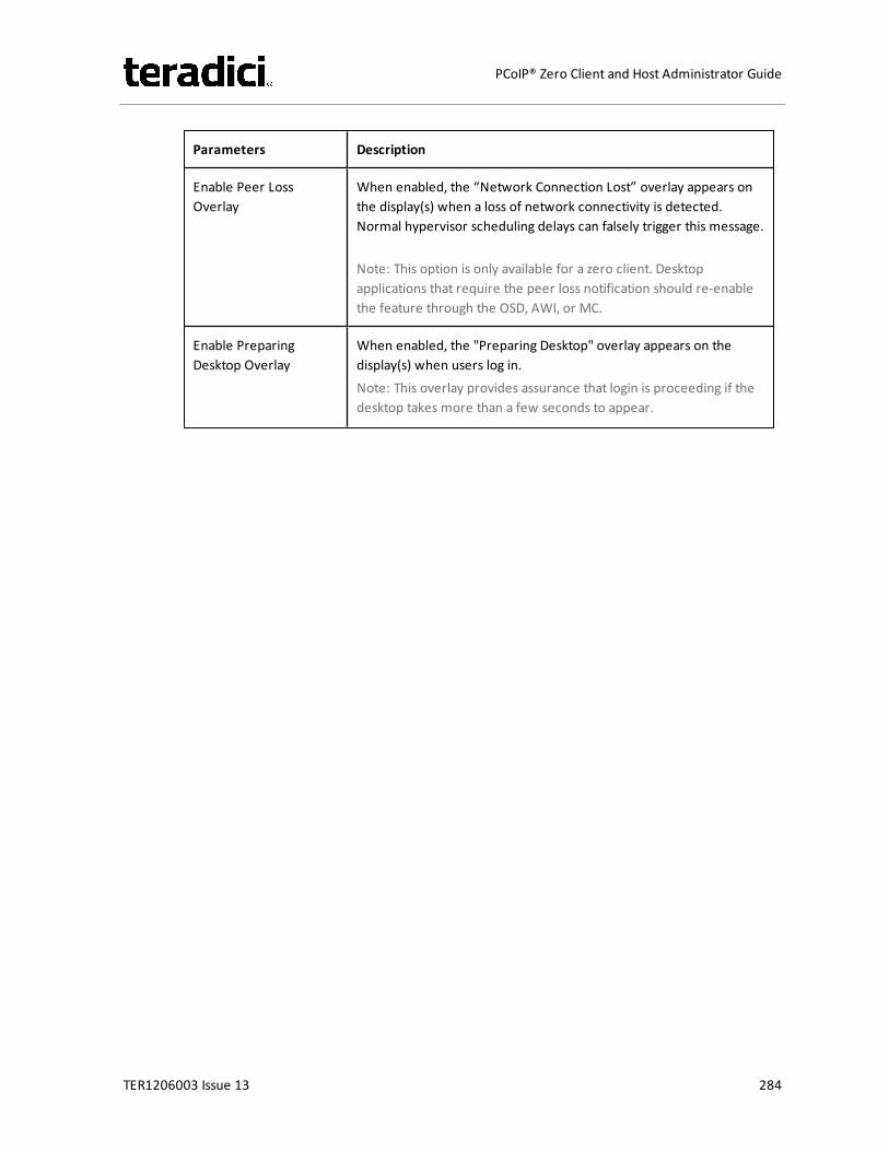
Parameters Description
Enable Peer LossOverlay
When enabled, the “Network Connection Lost” overlay appears onthe display(s) when a loss of network connectivity is detected.Normal hypervisor scheduling delays can falsely trigger this message.
Note: This option is only available for a zero client. Desktopapplications that require the peer loss notification should re-enablethe feature through the OSD, AWI, or MC.
Enable PreparingDesktop Overlay
When enabled, the "Preparing Desktop" overlay appears on thedisplay(s) when users log in.Note: This overlay provides assurance that login is proceeding if thedesktop takes more than a few seconds to appear.
TER1206003 Issue 13 284
PCoIP® Zero Client and Host Administrator Guide

Parameters Description
Disconnect MessageFilter
This field lets you control what type of messages appear when asession is disconnected. There are three categories:Information: User- or administrator-initiated actions affecting thesession:l You have been disconnected because you logged in from
another location or your host was shut down or restarted.l You have been disconnected because an administrator
disconnected you.l You have been disconnected because you logged in from
another location.l You have been disconnected because you disconnected from
your workstation.Warning: System-initiated, but expected actions affecting thesession:l You have been disconnected because your session timed out.Error: Unexpected system-initiated actions causing session to fail:l You have been disconnected.l Unable to connect (0x1001). Please contact your IT
administrator.l Unable to connect (0x1002). Please contact your IT
administrator.l Session closed remotely.l Session closed remotely (unknown cause).l You have been disconnected due to a configuration error
(0x100). Please contact your IT administrator for assistance.l You have been disconnected due to a configuration error
(0x201). Please contact your IT administrator for assistance.l You have been disconnected due to a configuration error
(0x300). Please contact your IT administrator for assistance.l You have been disconnected due to a configuration error
(0x301). Please contact your IT administrator for assistance.l You have been disconnected due to a configuration error
(0x302). Please contact your IT administrator for assistance.l You have been disconnected due to a configuration error
(0x303). Please contact your IT administrator for assistance.l You have been disconnected due to a configuration error
(0x305). Please contact your IT administrator for assistance.l You have been disconnected due to a configuration error
(0x400). Please contact your IT administrator for assistance.l You have been disconnected due to a configuration error
TER1206003 Issue 13 285
PCoIP® Zero Client and Host Administrator Guide
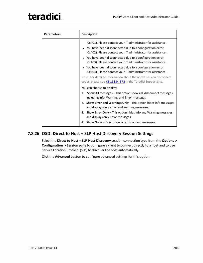
Parameters Description
(0x401). Please contact your IT administrator for assistance.l You have been disconnected due to a configuration error
(0x402). Please contact your IT administrator for assistance.l You have been disconnected due to a configuration error
(0x403). Please contact your IT administrator for assistance.l You have been disconnected due to a configuration error
(0x404). Please contact your IT administrator for assistance.Note: For detailed information about the above session disconnectcodes, please see KB 15134-872 in the Teradici Support Site.
You can choose to display:1. Show Allmessages – This option shows all disconnect messages
including Info, Warning, and Error messages.2. Show Error and Warnings Only – This option hides info messages
and displays only error and warning messages.3. Show Error Only – This option hides Info and Warning messages
and displays only Error messages.4. Show None – Don’t show any disconnect messages.
7.8.26 OSD: Direct to Host + SLP Host Discovery Session SettingsSelect theDirect to Host + SLP Host Discovery session connection type from theOptions >Configuration > Session page to configure a client to connect directly to a host and to useService Location Protocol (SLP) to discover the host automatically.
Click the Advanced button to configure advanced settings for this option.
TER1206003 Issue 13 286
PCoIP® Zero Client and Host Administrator Guide
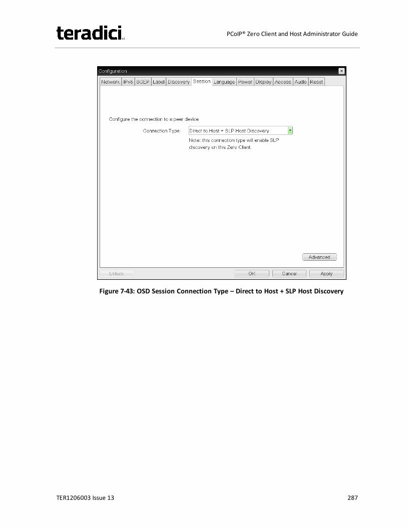
Figure 7-43: OSD Session Connection Type – Direct to Host + SLP Host Discovery
TER1206003 Issue 13 287
PCoIP® Zero Client and Host Administrator Guide
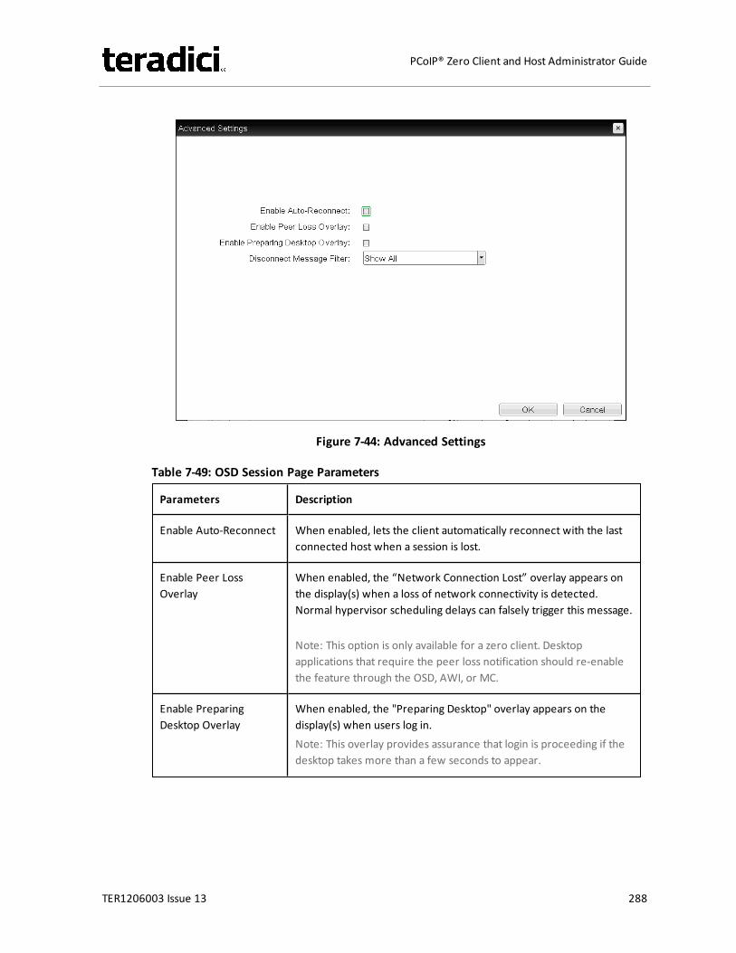
Figure 7-44: Advanced Settings
Table 7-49: OSD Session Page Parameters
Parameters Description
Enable Auto-Reconnect When enabled, lets the client automatically reconnect with the lastconnected host when a session is lost.
Enable Peer LossOverlay
When enabled, the “Network Connection Lost” overlay appears onthe display(s) when a loss of network connectivity is detected.Normal hypervisor scheduling delays can falsely trigger this message.
Note: This option is only available for a zero client. Desktopapplications that require the peer loss notification should re-enablethe feature through the OSD, AWI, or MC.
Enable PreparingDesktop Overlay
When enabled, the "Preparing Desktop" overlay appears on thedisplay(s) when users log in.Note: This overlay provides assurance that login is proceeding if thedesktop takes more than a few seconds to appear.
TER1206003 Issue 13 288
PCoIP® Zero Client and Host Administrator Guide

Parameters Description
Disconnect MessageFilter
This field lets you control what type of messages appear when asession is disconnected. There are three categories:Information: User- or administrator-initiated actions affecting thesession:l You have been disconnected because you logged in from
another location or your host was shut down or restarted.l You have been disconnected because an administrator
disconnected you.l You have been disconnected because you logged in from
another location.l You have been disconnected because you disconnected from
your workstation.Warning: System-initiated, but expected actions affecting thesession:l You have been disconnected because your session timed out.Error: Unexpected system-initiated actions causing session to fail:l You have been disconnected.l Unable to connect (0x1001). Please contact your IT
administrator.l Unable to connect (0x1002). Please contact your IT
administrator.l Session closed remotely.l Session closed remotely (unknown cause).l You have been disconnected due to a configuration error
(0x100). Please contact your IT administrator for assistance.l You have been disconnected due to a configuration error
(0x201). Please contact your IT administrator for assistance.l You have been disconnected due to a configuration error
(0x300). Please contact your IT administrator for assistance.l You have been disconnected due to a configuration error
(0x301). Please contact your IT administrator for assistance.l You have been disconnected due to a configuration error
(0x302). Please contact your IT administrator for assistance.l You have been disconnected due to a configuration error
(0x303). Please contact your IT administrator for assistance.l You have been disconnected due to a configuration error
(0x305). Please contact your IT administrator for assistance.l You have been disconnected due to a configuration error
(0x400). Please contact your IT administrator for assistance.l You have been disconnected due to a configuration error
TER1206003 Issue 13 289
PCoIP® Zero Client and Host Administrator Guide

Parameters Description
(0x401). Please contact your IT administrator for assistance.l You have been disconnected due to a configuration error
(0x402). Please contact your IT administrator for assistance.l You have been disconnected due to a configuration error
(0x403). Please contact your IT administrator for assistance.l You have been disconnected due to a configuration error
(0x404). Please contact your IT administrator for assistance.Note: For detailed information about the above session disconnectcodes, please see KB 15134-872 in the Teradici Support Site.
You can choose to display:1. Show Allmessages – This option shows all disconnect messages
including Info, Warning, and Error messages.2. Show Error and Warnings Only – This option hides info messages
and displays only error and warning messages.3. Show Error Only – This option hides Info and Warning messages
and displays only Error messages.4. Show None – Don’t show any disconnect messages.
7.8.27 OSD Tera2: PCoIP Connection Manager Session SettingsSelect the PCoIP Connection Manager session connection type from theOptions >Configuration > Session page to configure the client to use a PCoIP Connection Manager asthe PCoIP session broker.
Click the Advanced button to configure advanced settings for this option.
TER1206003 Issue 13 290
PCoIP® Zero Client and Host Administrator Guide
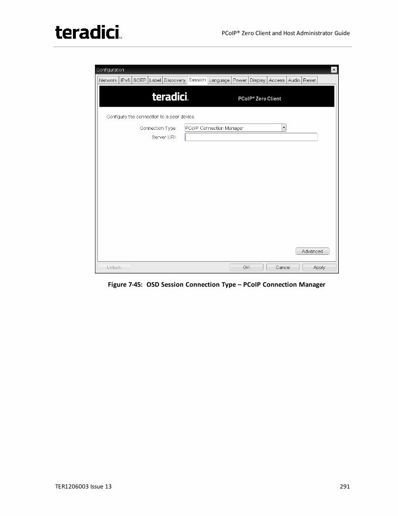
Figure 7-45: OSD Session Connection Type – PCoIP Connection Manager
TER1206003 Issue 13 291
PCoIP® Zero Client and Host Administrator Guide
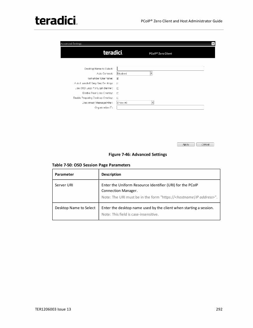
Figure 7-46: Advanced Settings
Table 7-50: OSD Session Page Parameters
Parameter Description
Server URI Enter the Uniform Resource Identifier (URI) for the PCoIPConnection Manager.Note: The URI must be in the form "https://<hostname|IP address>".
Desktop Name to Select Enter the desktop name used by the client when starting a session.Note: This field is case-insensitive.
TER1206003 Issue 13 292
PCoIP® Zero Client and Host Administrator Guide
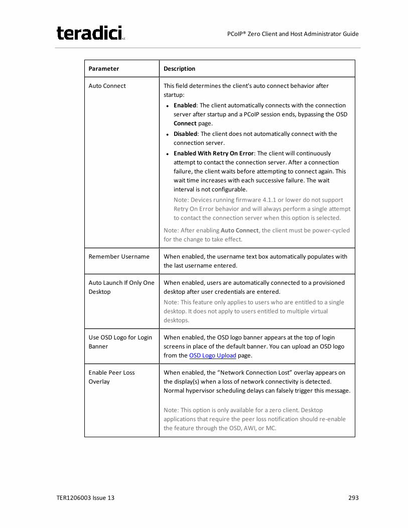
Parameter Description
Auto Connect This field determines the client's auto connect behavior afterstartup:l Enabled: The client automatically connects with the connection
server after startup and a PCoIP session ends, bypassing the OSDConnect page.
l Disabled: The client does not automatically connect with theconnection server.
l Enabled With Retry On Error: The client will continuouslyattempt to contact the connection server. After a connectionfailure, the client waits before attempting to connect again. Thiswait time increases with each successive failure. The waitinterval is not configurable.Note: Devices running firmware 4.1.1 or lower do not supportRetry On Error behavior and will always perform a single attemptto contact the connection server when this option is selected.
Note: After enabling Auto Connect, the client must be power-cycledfor the change to take effect.
Remember Username When enabled, the username text box automatically populates withthe last username entered.
Auto Launch If Only OneDesktop
When enabled, users are automatically connected to a provisioneddesktop after user credentials are entered.Note: This feature only applies to users who are entitled to a singledesktop. It does not apply to users entitled to multiple virtualdesktops.
Use OSD Logo for LoginBanner
When enabled, the OSD logo banner appears at the top of loginscreens in place of the default banner. You can upload an OSD logofrom the OSD Logo Upload page.
Enable Peer LossOverlay
When enabled, the “Network Connection Lost” overlay appears onthe display(s) when a loss of network connectivity is detected.Normal hypervisor scheduling delays can falsely trigger this message.
Note: This option is only available for a zero client. Desktopapplications that require the peer loss notification should re-enablethe feature through the OSD, AWI, or MC.
TER1206003 Issue 13 293
PCoIP® Zero Client and Host Administrator Guide

Parameter Description
Enable PreparingDesktop Overlay
When enabled, the "Preparing Desktop" overlay appears on thedisplay(s) when users log in.Note: This overlay provides assurance that login is proceeding if thedesktop takes more than a few seconds to appear.
TER1206003 Issue 13 294
PCoIP® Zero Client and Host Administrator Guide

Parameter Description
Disconnect MessageFilter
This field lets you control what type of messages appear when asession is disconnected. There are three categories:Information: User- or administrator-initiated actions affecting thesession:l You have been disconnected because you logged in from
another location or your host was shut down or restarted.l You have been disconnected because an administrator
disconnected you.l You have been disconnected because you logged in from
another location.l You have been disconnected because you disconnected from
your workstation.Warning: System-initiated, but expected actions affecting thesession:l You have been disconnected because your session timed out.Error: Unexpected system-initiated actions causing session to fail:l You have been disconnected.l Unable to connect (0x1001). Please contact your IT
administrator.l Unable to connect (0x1002). Please contact your IT
administrator.l Session closed remotely.l Session closed remotely (unknown cause).l You have been disconnected due to a configuration error
(0x100). Please contact your IT administrator for assistance.l You have been disconnected due to a configuration error
(0x201). Please contact your IT administrator for assistance.l You have been disconnected due to a configuration error
(0x300). Please contact your IT administrator for assistance.l You have been disconnected due to a configuration error
(0x301). Please contact your IT administrator for assistance.l You have been disconnected due to a configuration error
(0x302). Please contact your IT administrator for assistance.l You have been disconnected due to a configuration error
(0x303). Please contact your IT administrator for assistance.l You have been disconnected due to a configuration error
(0x305). Please contact your IT administrator for assistance.l You have been disconnected due to a configuration error
(0x400). Please contact your IT administrator for assistance.l You have been disconnected due to a configuration error
TER1206003 Issue 13 295
PCoIP® Zero Client and Host Administrator Guide
Parameter Description
(0x401). Please contact your IT administrator for assistance.l You have been disconnected due to a configuration error
(0x402). Please contact your IT administrator for assistance.l You have been disconnected due to a configuration error
(0x403). Please contact your IT administrator for assistance.l You have been disconnected due to a configuration error
(0x404). Please contact your IT administrator for assistance.Note: For detailed information about the above session disconnectcodes, please see KB 15134-872 in the Teradici Support Site.
You can choose to display:1. Show Allmessages – This option shows all disconnect messages
including Info, Warning, and Error messages.2. Show Error and Warnings Only – This option hides info messages
and displays only error and warning messages.3. Show Error Only – This option hides Info and Warning messages
and displays only Error messages.4. Show None – Don’t show any disconnect messages.
Organization ID Enter an organization ID for the company (e.g., "mycompany.com").This field accepts any UTF-8 character.Note: You only need to specify this parameter if the PCoIPConnection Manager requests it. The organization ID is used forcertain types of PCoIP Broker Protocol authentication messages.
7.8.28 OSD Tera2: PCoIP Connection Manager + Auto-Logon Session SettingsSelect the PCoIP Connection Manager + Auto-Logon session connection type from theOptions > Configuration > Session page to configure a client to automatically enter a user'slogin details when a PCoIP Connection Manager is used as the PCoIP session broker.
Click the Advanced button to configure advanced settings for this option.
Important! Passwords are stored locally in retrievable form when zero clients are configuredwith this session connection type. For this reason, it should not be used in high securityenvironments. Ensure that you take precautions to prevent theft of the zero client if you douse this session connection type.
TER1206003 Issue 13 296
PCoIP® Zero Client and Host Administrator Guide
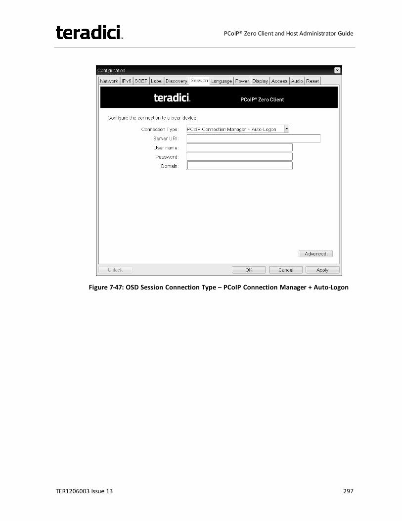
Figure 7-47: OSD Session Connection Type – PCoIP Connection Manager + Auto-Logon
TER1206003 Issue 13 297
PCoIP® Zero Client and Host Administrator Guide
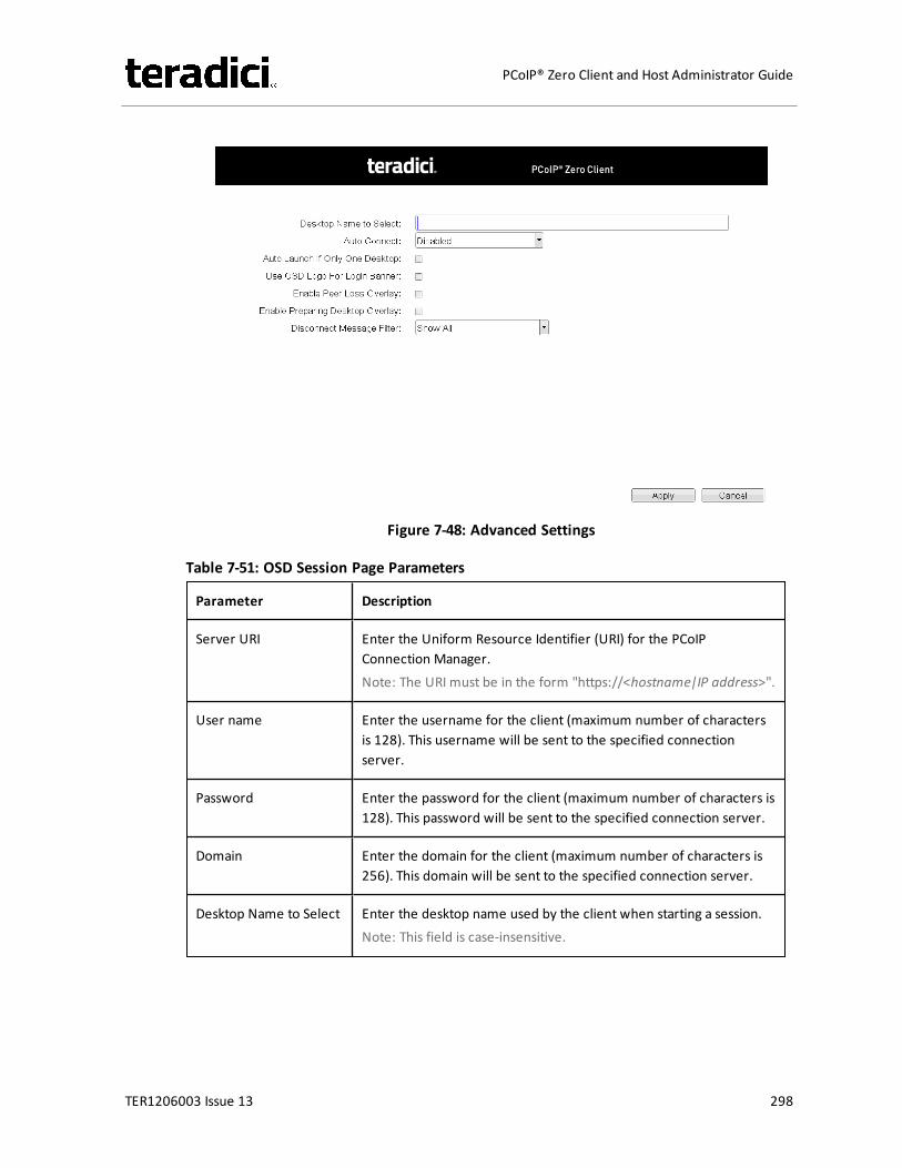
Figure 7-48: Advanced Settings
Table 7-51: OSD Session Page Parameters
Parameter Description
Server URI Enter the Uniform Resource Identifier (URI) for the PCoIPConnection Manager.Note: The URI must be in the form "https://<hostname|IP address>".
User name Enter the username for the client (maximum number of charactersis 128). This username will be sent to the specified connectionserver.
Password Enter the password for the client (maximum number of characters is128). This password will be sent to the specified connection server.
Domain Enter the domain for the client (maximum number of characters is256). This domain will be sent to the specified connection server.
Desktop Name to Select Enter the desktop name used by the client when starting a session.Note: This field is case-insensitive.
TER1206003 Issue 13 298
PCoIP® Zero Client and Host Administrator Guide
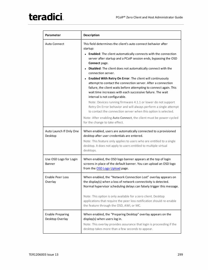
Parameter Description
Auto Connect This field determines the client's auto connect behavior afterstartup:l Enabled: The client automatically connects with the connection
server after startup and a PCoIP session ends, bypassing the OSDConnect page.
l Disabled: The client does not automatically connect with theconnection server.
l Enabled With Retry On Error: The client will continuouslyattempt to contact the connection server. After a connectionfailure, the client waits before attempting to connect again. Thiswait time increases with each successive failure. The waitinterval is not configurable.Note: Devices running firmware 4.1.1 or lower do not supportRetry On Error behavior and will always perform a single attemptto contact the connection server when this option is selected.
Note: After enabling Auto Connect, the client must be power-cycledfor the change to take effect.
Auto Launch If Only OneDesktop
When enabled, users are automatically connected to a provisioneddesktop after user credentials are entered.Note: This feature only applies to users who are entitled to a singledesktop. It does not apply to users entitled to multiple virtualdesktops.
Use OSD Logo for LoginBanner
When enabled, the OSD logo banner appears at the top of loginscreens in place of the default banner. You can upload an OSD logofrom the OSD Logo Upload page.
Enable Peer LossOverlay
When enabled, the “Network Connection Lost” overlay appears onthe display(s) when a loss of network connectivity is detected.Normal hypervisor scheduling delays can falsely trigger this message.
Note: This option is only available for a zero client. Desktopapplications that require the peer loss notification should re-enablethe feature through the OSD, AWI, or MC.
Enable PreparingDesktop Overlay
When enabled, the "Preparing Desktop" overlay appears on thedisplay(s) when users log in.Note: This overlay provides assurance that login is proceeding if thedesktop takes more than a few seconds to appear.
TER1206003 Issue 13 299
PCoIP® Zero Client and Host Administrator Guide

Parameter Description
Disconnect MessageFilter
This field lets you control what type of messages appear when asession is disconnected. There are three categories:Information: User- or administrator-initiated actions affecting thesession:l You have been disconnected because you logged in from
another location or your host was shut down or restarted.l You have been disconnected because an administrator
disconnected you.l You have been disconnected because you logged in from
another location.l You have been disconnected because you disconnected from
your workstation.Warning: System-initiated, but expected actions affecting thesession:l You have been disconnected because your session timed out.Error: Unexpected system-initiated actions causing session to fail:l You have been disconnected.l Unable to connect (0x1001). Please contact your IT
administrator.l Unable to connect (0x1002). Please contact your IT
administrator.l Session closed remotely.l Session closed remotely (unknown cause).l You have been disconnected due to a configuration error
(0x100). Please contact your IT administrator for assistance.l You have been disconnected due to a configuration error
(0x201). Please contact your IT administrator for assistance.l You have been disconnected due to a configuration error
(0x300). Please contact your IT administrator for assistance.l You have been disconnected due to a configuration error
(0x301). Please contact your IT administrator for assistance.l You have been disconnected due to a configuration error
(0x302). Please contact your IT administrator for assistance.l You have been disconnected due to a configuration error
(0x303). Please contact your IT administrator for assistance.l You have been disconnected due to a configuration error
(0x305). Please contact your IT administrator for assistance.l You have been disconnected due to a configuration error
(0x400). Please contact your IT administrator for assistance.l You have been disconnected due to a configuration error
TER1206003 Issue 13 300
PCoIP® Zero Client and Host Administrator Guide
Parameter Description
(0x401). Please contact your IT administrator for assistance.l You have been disconnected due to a configuration error
(0x402). Please contact your IT administrator for assistance.l You have been disconnected due to a configuration error
(0x403). Please contact your IT administrator for assistance.l You have been disconnected due to a configuration error
(0x404). Please contact your IT administrator for assistance.Note: For detailed information about the above session disconnectcodes, please see KB 15134-872 in the Teradici Support Site.
You can choose to display:1. Show Allmessages – This option shows all disconnect messages
including Info, Warning, and Error messages.2. Show Error and Warnings Only – This option hides info messages
and displays only error and warning messages.3. Show Error Only – This option hides Info and Warning messages
and displays only Error messages.4. Show None – Don’t show any disconnect messages.
7.8.29 OSD: View Connection Server Session SettingsSelect the View Connection Server session connection type from theOptions >Configuration > Session page to configure a client to use a View Connection Server as thebroker when connecting to a VMware desktop.
Click the Advanced button to configure advanced settings for this option.
TER1206003 Issue 13 301
PCoIP® Zero Client and Host Administrator Guide
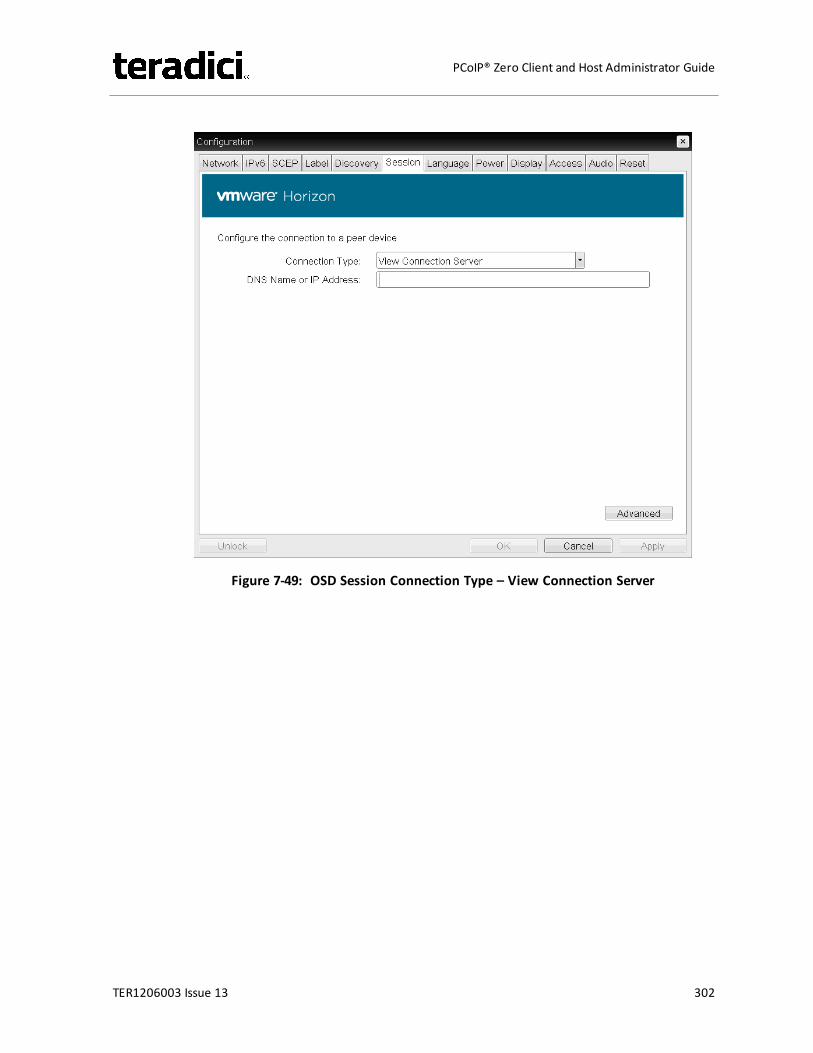
Figure 7-49: OSD Session Connection Type – View Connection Server
TER1206003 Issue 13 302
PCoIP® Zero Client and Host Administrator Guide
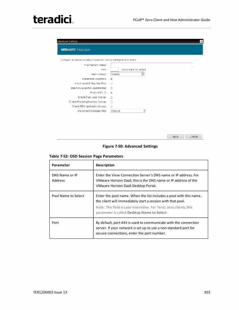
Figure 7-50: Advanced Settings
Table 7-52: OSD Session Page Parameters
Parameter Description
DNS Name or IPAddress
Enter the View Connection Server's DNS name or IP address. ForVMware Horizon DaaS, this is the DNS name or IP address of theVMware Horizon DaaS Desktop Portal.
Pool Name to Select Enter the pool name. When the list includes a pool with this name,the client will immediately start a session with that pool.Note: This field is case-insensitive. For Tera1 zero clients, thisparameter is called Desktop Name to Select.
Port By default, port 443 is used to communicate with the connectionserver. If your network is set up to use a non-standard port forsecure connections, enter the port number.
TER1206003 Issue 13 303
PCoIP® Zero Client and Host Administrator Guide
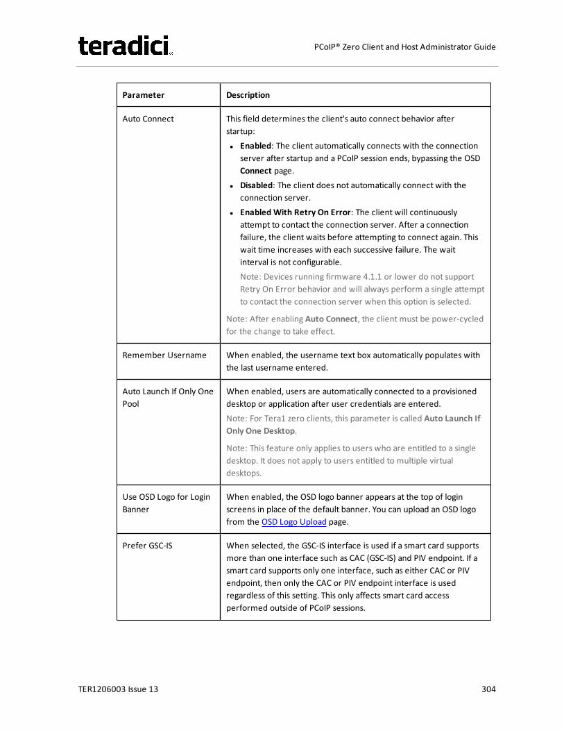
Parameter Description
Auto Connect This field determines the client's auto connect behavior afterstartup:l Enabled: The client automatically connects with the connection
server after startup and a PCoIP session ends, bypassing the OSDConnect page.
l Disabled: The client does not automatically connect with theconnection server.
l Enabled With Retry On Error: The client will continuouslyattempt to contact the connection server. After a connectionfailure, the client waits before attempting to connect again. Thiswait time increases with each successive failure. The waitinterval is not configurable.Note: Devices running firmware 4.1.1 or lower do not supportRetry On Error behavior and will always perform a single attemptto contact the connection server when this option is selected.
Note: After enabling Auto Connect, the client must be power-cycledfor the change to take effect.
Remember Username When enabled, the username text box automatically populates withthe last username entered.
Auto Launch If Only OnePool
When enabled, users are automatically connected to a provisioneddesktop or application after user credentials are entered.Note: For Tera1 zero clients, this parameter is called Auto Launch IfOnly One Desktop.
Note: This feature only applies to users who are entitled to a singledesktop. It does not apply to users entitled to multiple virtualdesktops.
Use OSD Logo for LoginBanner
When enabled, the OSD logo banner appears at the top of loginscreens in place of the default banner. You can upload an OSD logofrom the OSD Logo Upload page.
Prefer GSC-IS When selected, the GSC-IS interface is used if a smart card supportsmore than one interface such as CAC (GSC-IS) and PIV endpoint. If asmart card supports only one interface, such as either CAC or PIVendpoint, then only the CAC or PIV endpoint interface is usedregardless of this setting. This only affects smart card accessperformed outside of PCoIP sessions.
TER1206003 Issue 13 304
PCoIP® Zero Client and Host Administrator Guide
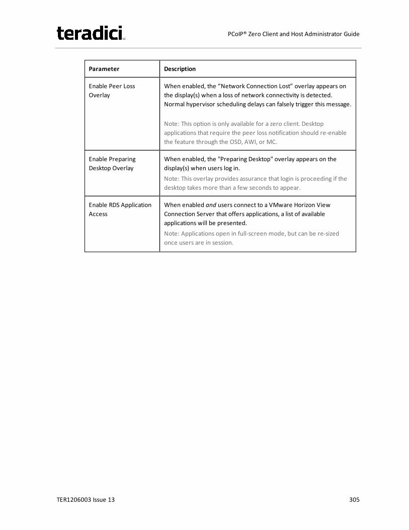
Parameter Description
Enable Peer LossOverlay
When enabled, the “Network Connection Lost” overlay appears onthe display(s) when a loss of network connectivity is detected.Normal hypervisor scheduling delays can falsely trigger this message.
Note: This option is only available for a zero client. Desktopapplications that require the peer loss notification should re-enablethe feature through the OSD, AWI, or MC.
Enable PreparingDesktop Overlay
When enabled, the "Preparing Desktop" overlay appears on thedisplay(s) when users log in.Note: This overlay provides assurance that login is proceeding if thedesktop takes more than a few seconds to appear.
Enable RDS ApplicationAccess
When enabled and users connect to a VMware Horizon ViewConnection Server that offers applications, a list of availableapplications will be presented.Note: Applications open in full-screen mode, but can be re-sizedonce users are in session.
TER1206003 Issue 13 305
PCoIP® Zero Client and Host Administrator Guide

Parameter Description
Disconnect MessageFilter
This field lets you control what type of messages appear when asession is disconnected. There are three categories:Information: User- or administrator-initiated actions affecting thesession:l You have been disconnected because you logged in from
another location or your host was shut down or restarted.l You have been disconnected because an administrator
disconnected you.l You have been disconnected because you logged in from
another location.l You have been disconnected because you disconnected from
your workstation.Warning: System-initiated, but expected actions affecting thesession:l You have been disconnected because your session timed out.Error: Unexpected system-initiated actions causing session to fail:l You have been disconnected.l Unable to connect (0x1001). Please contact your IT
administrator.l Unable to connect (0x1002). Please contact your IT
administrator.l Session closed remotely.l Session closed remotely (unknown cause).l You have been disconnected due to a configuration error
(0x100). Please contact your IT administrator for assistance.l You have been disconnected due to a configuration error
(0x201). Please contact your IT administrator for assistance.l You have been disconnected due to a configuration error
(0x300). Please contact your IT administrator for assistance.l You have been disconnected due to a configuration error
(0x301). Please contact your IT administrator for assistance.l You have been disconnected due to a configuration error
(0x302). Please contact your IT administrator for assistance.l You have been disconnected due to a configuration error
(0x303). Please contact your IT administrator for assistance.l You have been disconnected due to a configuration error
(0x305). Please contact your IT administrator for assistance.l You have been disconnected due to a configuration error
(0x400). Please contact your IT administrator for assistance.l You have been disconnected due to a configuration error
TER1206003 Issue 13 306
PCoIP® Zero Client and Host Administrator Guide
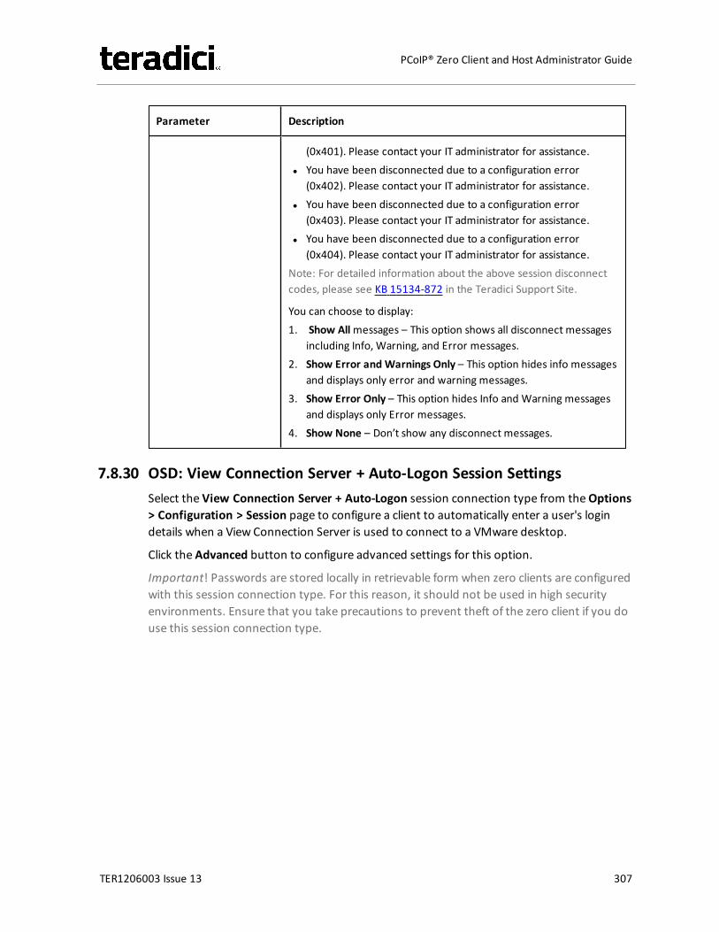
Parameter Description
(0x401). Please contact your IT administrator for assistance.l You have been disconnected due to a configuration error
(0x402). Please contact your IT administrator for assistance.l You have been disconnected due to a configuration error
(0x403). Please contact your IT administrator for assistance.l You have been disconnected due to a configuration error
(0x404). Please contact your IT administrator for assistance.Note: For detailed information about the above session disconnectcodes, please see KB 15134-872 in the Teradici Support Site.
You can choose to display:1. Show Allmessages – This option shows all disconnect messages
including Info, Warning, and Error messages.2. Show Error and Warnings Only – This option hides info messages
and displays only error and warning messages.3. Show Error Only – This option hides Info and Warning messages
and displays only Error messages.4. Show None – Don’t show any disconnect messages.
7.8.30 OSD: View Connection Server + Auto-Logon Session SettingsSelect the View Connection Server + Auto-Logon session connection type from theOptions> Configuration > Session page to configure a client to automatically enter a user's logindetails when a View Connection Server is used to connect to a VMware desktop.
Click the Advanced button to configure advanced settings for this option.
Important! Passwords are stored locally in retrievable form when zero clients are configuredwith this session connection type. For this reason, it should not be used in high securityenvironments. Ensure that you take precautions to prevent theft of the zero client if you douse this session connection type.
TER1206003 Issue 13 307
PCoIP® Zero Client and Host Administrator Guide

Figure 7-51: OSD Session Connection Type – View Connection Server + Auto-Logon
TER1206003 Issue 13 308
PCoIP® Zero Client and Host Administrator Guide
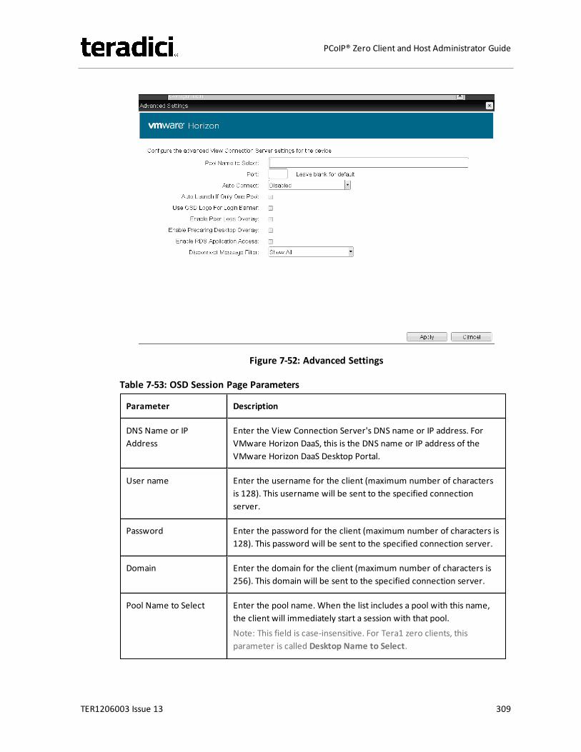
Figure 7-52: Advanced Settings
Table 7-53: OSD Session Page Parameters
Parameter Description
DNS Name or IPAddress
Enter the View Connection Server's DNS name or IP address. ForVMware Horizon DaaS, this is the DNS name or IP address of theVMware Horizon DaaS Desktop Portal.
User name Enter the username for the client (maximum number of charactersis 128). This username will be sent to the specified connectionserver.
Password Enter the password for the client (maximum number of characters is128). This password will be sent to the specified connection server.
Domain Enter the domain for the client (maximum number of characters is256). This domain will be sent to the specified connection server.
Pool Name to Select Enter the pool name. When the list includes a pool with this name,the client will immediately start a session with that pool.Note: This field is case-insensitive. For Tera1 zero clients, thisparameter is called Desktop Name to Select.
TER1206003 Issue 13 309
PCoIP® Zero Client and Host Administrator Guide
Parameter Description
Port By default, port 443 is used to communicate with the connectionserver. If your network is set up to use a non-standard port forsecure connections, enter the port number.
Auto Connect This field determines the client's auto connect behavior afterstartup:l Enabled: The client automatically connects with the connection
server after startup and a PCoIP session ends, bypassing the OSDConnect page.
l Disabled: The client does not automatically connect with theconnection server.
l Enabled With Retry On Error: The client will continuouslyattempt to contact the connection server. After a connectionfailure, the client waits before attempting to connect again. Thiswait time increases with each successive failure. The waitinterval is not configurable.Note: Devices running firmware 4.1.1 or lower do not supportRetry On Error behavior and will always perform a single attemptto contact the connection server when this option is selected.
Note: After enabling Auto Connect, the client must be power-cycledfor the change to take effect.
Auto Launch If Only OnePool
When enabled, users are automatically connected to a provisioneddesktop or application after user credentials are entered.Note: For Tera1 zero clients, this parameter is called Auto Launch IfOnly One Desktop.
Note: This feature only applies to users who are entitled to a singledesktop. It does not apply to users entitled to multiple virtualdesktops.
Use OSD Logo for LoginBanner
When enabled, the OSD logo banner appears at the top of loginscreens in place of the default banner. You can upload an OSD logofrom the OSD Logo Upload page.
Enable Peer LossOverlay
When enabled, the “Network Connection Lost” overlay appears onthe display(s) when a loss of network connectivity is detected.Normal hypervisor scheduling delays can falsely trigger this message.
Note: This option is only available for a zero client. Desktopapplications that require the peer loss notification should re-enablethe feature through the OSD, AWI, or MC.
TER1206003 Issue 13 310
PCoIP® Zero Client and Host Administrator Guide
Parameter Description
Enable PreparingDesktop Overlay
When enabled, the "Preparing Desktop" overlay appears on thedisplay(s) when users log in.Note: This overlay provides assurance that login is proceeding if thedesktop takes more than a few seconds to appear.
Enable RDS ApplicationAccess
When enabled and users connect to a VMware Horizon ViewConnection Server that offers applications, a list of availableapplications will be presented.Note: Applications open in full-screen mode, but can be re-sizedonce users are in session.
TER1206003 Issue 13 311
PCoIP® Zero Client and Host Administrator Guide

Parameter Description
Disconnect MessageFilter
This field lets you control what type of messages appear when asession is disconnected. There are three categories:Information: User- or administrator-initiated actions affecting thesession:l You have been disconnected because you logged in from
another location or your host was shut down or restarted.l You have been disconnected because an administrator
disconnected you.l You have been disconnected because you logged in from
another location.l You have been disconnected because you disconnected from
your workstation.Warning: System-initiated, but expected actions affecting thesession:l You have been disconnected because your session timed out.Error: Unexpected system-initiated actions causing session to fail:l You have been disconnected.l Unable to connect (0x1001). Please contact your IT
administrator.l Unable to connect (0x1002). Please contact your IT
administrator.l Session closed remotely.l Session closed remotely (unknown cause).l You have been disconnected due to a configuration error
(0x100). Please contact your IT administrator for assistance.l You have been disconnected due to a configuration error
(0x201). Please contact your IT administrator for assistance.l You have been disconnected due to a configuration error
(0x300). Please contact your IT administrator for assistance.l You have been disconnected due to a configuration error
(0x301). Please contact your IT administrator for assistance.l You have been disconnected due to a configuration error
(0x302). Please contact your IT administrator for assistance.l You have been disconnected due to a configuration error
(0x303). Please contact your IT administrator for assistance.l You have been disconnected due to a configuration error
(0x305). Please contact your IT administrator for assistance.l You have been disconnected due to a configuration error
(0x400). Please contact your IT administrator for assistance.l You have been disconnected due to a configuration error
TER1206003 Issue 13 312
PCoIP® Zero Client and Host Administrator Guide
Parameter Description
(0x401). Please contact your IT administrator for assistance.l You have been disconnected due to a configuration error
(0x402). Please contact your IT administrator for assistance.l You have been disconnected due to a configuration error
(0x403). Please contact your IT administrator for assistance.l You have been disconnected due to a configuration error
(0x404). Please contact your IT administrator for assistance.Note: For detailed information about the above session disconnectcodes, please see KB 15134-872 in the Teradici Support Site.
You can choose to display:1. Show Allmessages – This option shows all disconnect messages
including Info, Warning, and Error messages.2. Show Error and Warnings Only – This option hides info messages
and displays only error and warning messages.3. Show Error Only – This option hides Info and Warning messages
and displays only Error messages.4. Show None – Don’t show any disconnect messages.
7.8.31 OSD: View Connection Server + Kiosk Session SettingsSelect the View Connection Server + Kiosk session connection type from theOptions >Configuration > Session page to configure a client to use Kiosk modewhen connecting to aVMware desktop via a View Connection Server.
Click the Advanced button to configure advanced settings for this option.
Important! Passwords are stored locally in retrievable form when zero clients are configuredwith this session connection type. For this reason, it should not be used in high securityenvironments. Ensure that you take precautions to prevent theft of the zero client if you douse this session connection type.
TER1206003 Issue 13 313
PCoIP® Zero Client and Host Administrator Guide
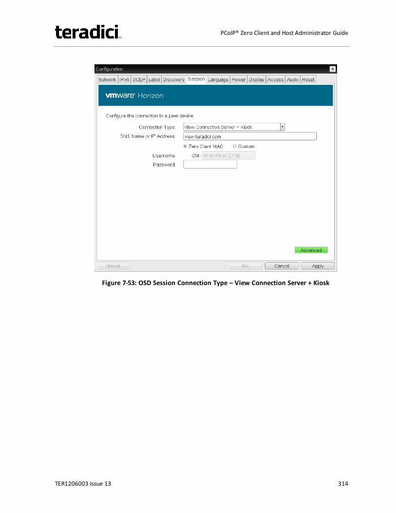
Figure 7-53: OSD Session Connection Type – View Connection Server + Kiosk
TER1206003 Issue 13 314
PCoIP® Zero Client and Host Administrator Guide
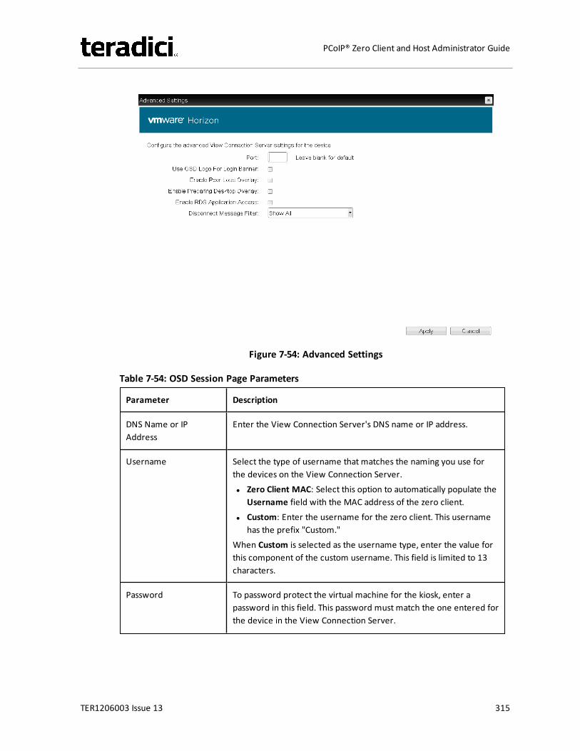
Figure 7-54: Advanced Settings
Table 7-54: OSD Session Page Parameters
Parameter Description
DNS Name or IPAddress
Enter the View Connection Server's DNS name or IP address.
Username Select the type of username that matches the naming you use forthe devices on the View Connection Server.l Zero Client MAC: Select this option to automatically populate the
Username field with the MAC address of the zero client.l Custom: Enter the username for the zero client. This username
has the prefix "Custom."When Custom is selected as the username type, enter the value forthis component of the custom username. This field is limited to 13characters.
Password To password protect the virtual machine for the kiosk, enter apassword in this field. This password must match the one entered forthe device in the View Connection Server.
TER1206003 Issue 13 315
PCoIP® Zero Client and Host Administrator Guide
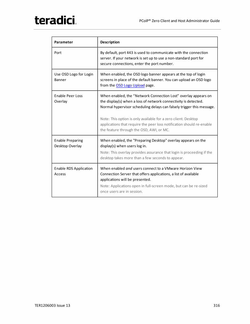
Parameter Description
Port By default, port 443 is used to communicate with the connectionserver. If your network is set up to use a non-standard port forsecure connections, enter the port number.
Use OSD Logo for LoginBanner
When enabled, the OSD logo banner appears at the top of loginscreens in place of the default banner. You can upload an OSD logofrom the OSD Logo Upload page.
Enable Peer LossOverlay
When enabled, the “Network Connection Lost” overlay appears onthe display(s) when a loss of network connectivity is detected.Normal hypervisor scheduling delays can falsely trigger this message.
Note: This option is only available for a zero client. Desktopapplications that require the peer loss notification should re-enablethe feature through the OSD, AWI, or MC.
Enable PreparingDesktop Overlay
When enabled, the "Preparing Desktop" overlay appears on thedisplay(s) when users log in.Note: This overlay provides assurance that login is proceeding if thedesktop takes more than a few seconds to appear.
Enable RDS ApplicationAccess
When enabled and users connect to a VMware Horizon ViewConnection Server that offers applications, a list of availableapplications will be presented.Note: Applications open in full-screen mode, but can be re-sizedonce users are in session.
TER1206003 Issue 13 316
PCoIP® Zero Client and Host Administrator Guide

Parameter Description
Disconnect MessageFilter
This field lets you control what type of messages appear when asession is disconnected. There are three categories:Information: User- or administrator-initiated actions affecting thesession:l You have been disconnected because you logged in from
another location or your host was shut down or restarted.l You have been disconnected because an administrator
disconnected you.l You have been disconnected because you logged in from
another location.l You have been disconnected because you disconnected from
your workstation.Warning: System-initiated, but expected actions affecting thesession:l You have been disconnected because your session timed out.Error: Unexpected system-initiated actions causing session to fail:l You have been disconnected.l Unable to connect (0x1001). Please contact your IT
administrator.l Unable to connect (0x1002). Please contact your IT
administrator.l Session closed remotely.l Session closed remotely (unknown cause).l You have been disconnected due to a configuration error
(0x100). Please contact your IT administrator for assistance.l You have been disconnected due to a configuration error
(0x201). Please contact your IT administrator for assistance.l You have been disconnected due to a configuration error
(0x300). Please contact your IT administrator for assistance.l You have been disconnected due to a configuration error
(0x301). Please contact your IT administrator for assistance.l You have been disconnected due to a configuration error
(0x302). Please contact your IT administrator for assistance.l You have been disconnected due to a configuration error
(0x303). Please contact your IT administrator for assistance.l You have been disconnected due to a configuration error
(0x305). Please contact your IT administrator for assistance.l You have been disconnected due to a configuration error
(0x400). Please contact your IT administrator for assistance.l You have been disconnected due to a configuration error
TER1206003 Issue 13 317
PCoIP® Zero Client and Host Administrator Guide
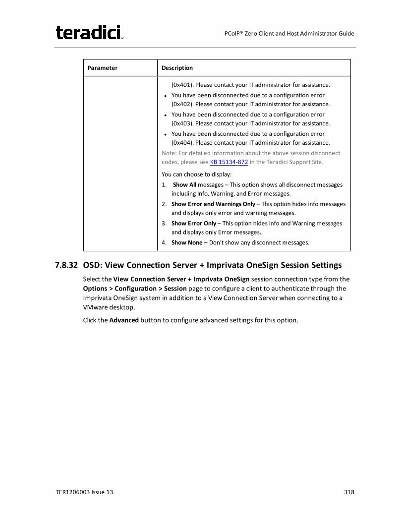
Parameter Description
(0x401). Please contact your IT administrator for assistance.l You have been disconnected due to a configuration error
(0x402). Please contact your IT administrator for assistance.l You have been disconnected due to a configuration error
(0x403). Please contact your IT administrator for assistance.l You have been disconnected due to a configuration error
(0x404). Please contact your IT administrator for assistance.Note: For detailed information about the above session disconnectcodes, please see KB 15134-872 in the Teradici Support Site.
You can choose to display:1. Show Allmessages – This option shows all disconnect messages
including Info, Warning, and Error messages.2. Show Error and Warnings Only – This option hides info messages
and displays only error and warning messages.3. Show Error Only – This option hides Info and Warning messages
and displays only Error messages.4. Show None – Don’t show any disconnect messages.
7.8.32 OSD: View Connection Server + Imprivata OneSign Session SettingsSelect the View Connection Server + Imprivata OneSign session connection type from theOptions > Configuration > Session page to configure a client to authenticate through theImprivata OneSign system in addition to a View Connection Server when connecting to aVMware desktop.
Click the Advanced button to configure advanced settings for this option.
TER1206003 Issue 13 318
PCoIP® Zero Client and Host Administrator Guide
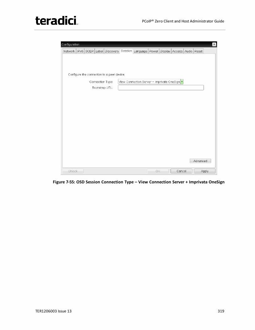
Figure 7-55: OSD Session Connection Type – View Connection Server + Imprivata OneSign
TER1206003 Issue 13 319
PCoIP® Zero Client and Host Administrator Guide
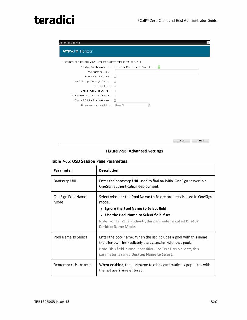
Figure 7-56: Advanced Settings
Table 7-55: OSD Session Page Parameters
Parameter Description
Bootstrap URL Enter the bootstrap URL used to find an initial OneSign server in aOneSign authentication deployment.
OneSign Pool NameMode
Select whether the Pool Name to Select property is used in OneSignmode.l Ignore the Pool Name to Select fieldl Use the Pool Name to Select field if setNote: For Tera1 zero clients, this parameter is called OneSignDesktop Name Mode.
Pool Name to Select Enter the pool name. When the list includes a pool with this name,the client will immediately start a session with that pool.Note: This field is case-insensitive. For Tera1 zero clients, thisparameter is called Desktop Name to Select.
Remember Username When enabled, the username text box automatically populates withthe last username entered.
TER1206003 Issue 13 320
PCoIP® Zero Client and Host Administrator Guide
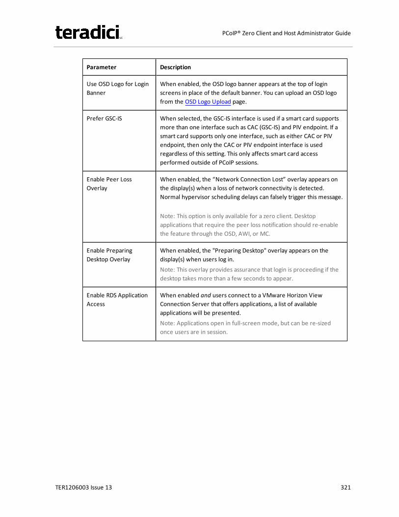
Parameter Description
Use OSD Logo for LoginBanner
When enabled, the OSD logo banner appears at the top of loginscreens in place of the default banner. You can upload an OSD logofrom the OSD Logo Upload page.
Prefer GSC-IS When selected, the GSC-IS interface is used if a smart card supportsmore than one interface such as CAC (GSC-IS) and PIV endpoint. If asmart card supports only one interface, such as either CAC or PIVendpoint, then only the CAC or PIV endpoint interface is usedregardless of this setting. This only affects smart card accessperformed outside of PCoIP sessions.
Enable Peer LossOverlay
When enabled, the “Network Connection Lost” overlay appears onthe display(s) when a loss of network connectivity is detected.Normal hypervisor scheduling delays can falsely trigger this message.
Note: This option is only available for a zero client. Desktopapplications that require the peer loss notification should re-enablethe feature through the OSD, AWI, or MC.
Enable PreparingDesktop Overlay
When enabled, the "Preparing Desktop" overlay appears on thedisplay(s) when users log in.Note: This overlay provides assurance that login is proceeding if thedesktop takes more than a few seconds to appear.
Enable RDS ApplicationAccess
When enabled and users connect to a VMware Horizon ViewConnection Server that offers applications, a list of availableapplications will be presented.Note: Applications open in full-screen mode, but can be re-sizedonce users are in session.
TER1206003 Issue 13 321
PCoIP® Zero Client and Host Administrator Guide

Parameter Description
Disconnect MessageFilter
This field lets you control what type of messages appear when asession is disconnected. There are three categories:Information: User- or administrator-initiated actions affecting thesession:l You have been disconnected because you logged in from
another location or your host was shut down or restarted.l You have been disconnected because an administrator
disconnected you.l You have been disconnected because you logged in from
another location.l You have been disconnected because you disconnected from
your workstation.Warning: System-initiated, but expected actions affecting thesession:l You have been disconnected because your session timed out.Error: Unexpected system-initiated actions causing session to fail:l You have been disconnected.l Unable to connect (0x1001). Please contact your IT
administrator.l Unable to connect (0x1002). Please contact your IT
administrator.l Session closed remotely.l Session closed remotely (unknown cause).l You have been disconnected due to a configuration error
(0x100). Please contact your IT administrator for assistance.l You have been disconnected due to a configuration error
(0x201). Please contact your IT administrator for assistance.l You have been disconnected due to a configuration error
(0x300). Please contact your IT administrator for assistance.l You have been disconnected due to a configuration error
(0x301). Please contact your IT administrator for assistance.l You have been disconnected due to a configuration error
(0x302). Please contact your IT administrator for assistance.l You have been disconnected due to a configuration error
(0x303). Please contact your IT administrator for assistance.l You have been disconnected due to a configuration error
(0x305). Please contact your IT administrator for assistance.l You have been disconnected due to a configuration error
(0x400). Please contact your IT administrator for assistance.l You have been disconnected due to a configuration error
TER1206003 Issue 13 322
PCoIP® Zero Client and Host Administrator Guide
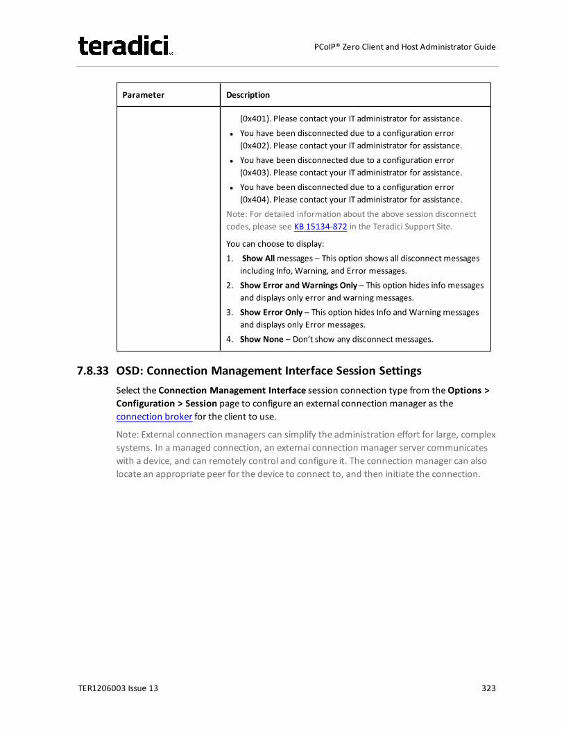
Parameter Description
(0x401). Please contact your IT administrator for assistance.l You have been disconnected due to a configuration error
(0x402). Please contact your IT administrator for assistance.l You have been disconnected due to a configuration error
(0x403). Please contact your IT administrator for assistance.l You have been disconnected due to a configuration error
(0x404). Please contact your IT administrator for assistance.Note: For detailed information about the above session disconnectcodes, please see KB 15134-872 in the Teradici Support Site.
You can choose to display:1. Show Allmessages – This option shows all disconnect messages
including Info, Warning, and Error messages.2. Show Error and Warnings Only – This option hides info messages
and displays only error and warning messages.3. Show Error Only – This option hides Info and Warning messages
and displays only Error messages.4. Show None – Don’t show any disconnect messages.
7.8.33 OSD: Connection Management Interface Session SettingsSelect the Connection Management Interface session connection type from theOptions >Configuration > Session page to configure an external connection manager as theconnection broker for the client to use.
Note: External connection managers can simplify the administration effort for large, complexsystems. In a managed connection, an external connection manager server communicateswith a device, and can remotely control and configure it. The connection manager can alsolocate an appropriate peer for the device to connect to, and then initiate the connection.
TER1206003 Issue 13 323
PCoIP® Zero Client and Host Administrator Guide
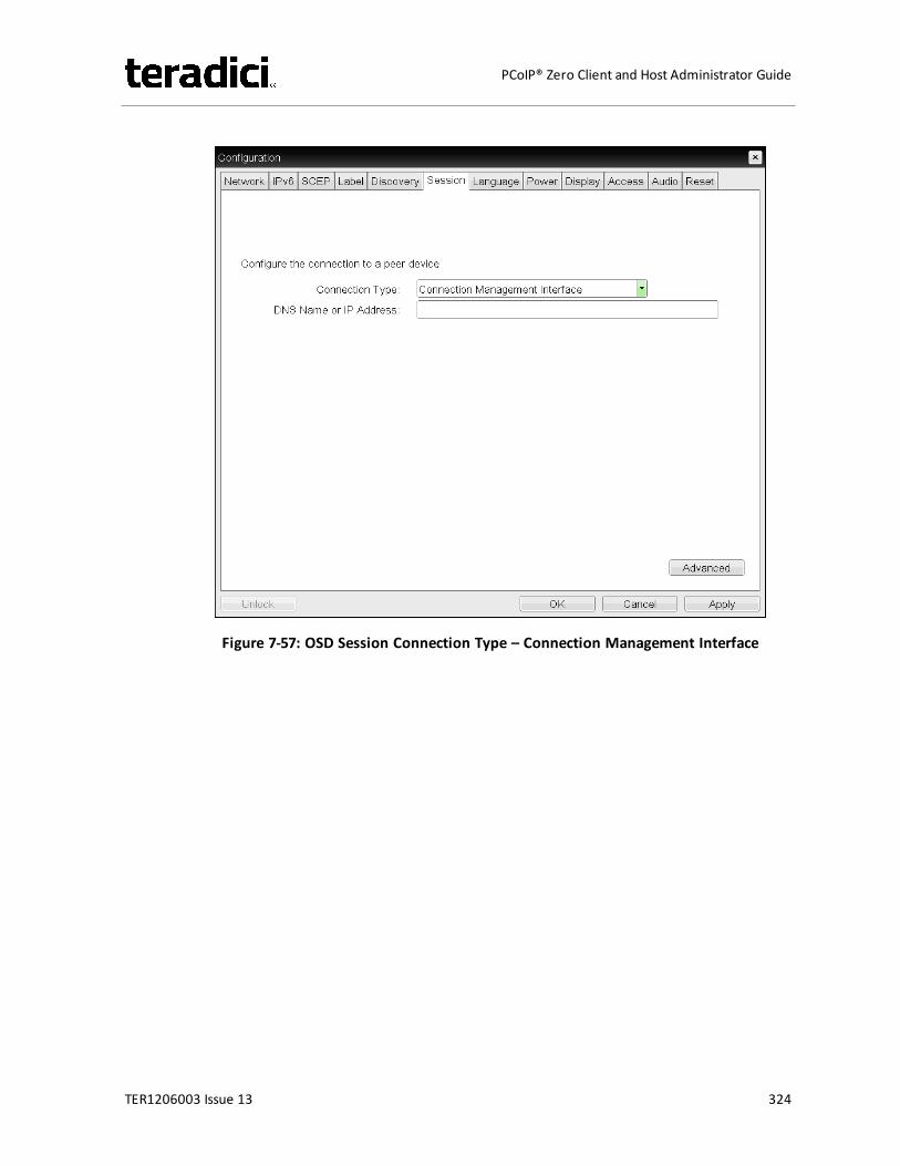
Figure 7-57: OSD Session Connection Type – Connection Management Interface
TER1206003 Issue 13 324
PCoIP® Zero Client and Host Administrator Guide
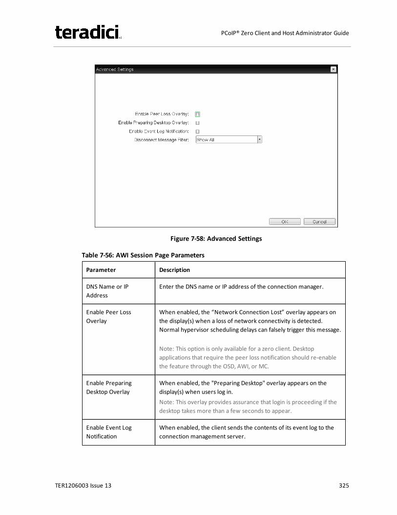
Figure 7-58: Advanced Settings
Table 7-56: AWI Session Page Parameters
Parameter Description
DNS Name or IPAddress
Enter the DNS name or IP address of the connection manager.
Enable Peer LossOverlay
When enabled, the “Network Connection Lost” overlay appears onthe display(s) when a loss of network connectivity is detected.Normal hypervisor scheduling delays can falsely trigger this message.
Note: This option is only available for a zero client. Desktopapplications that require the peer loss notification should re-enablethe feature through the OSD, AWI, or MC.
Enable PreparingDesktop Overlay
When enabled, the "Preparing Desktop" overlay appears on thedisplay(s) when users log in.Note: This overlay provides assurance that login is proceeding if thedesktop takes more than a few seconds to appear.
Enable Event LogNotification
When enabled, the client sends the contents of its event log to theconnection management server.
TER1206003 Issue 13 325
PCoIP® Zero Client and Host Administrator Guide

Parameter Description
Disconnect MessageFilter
This field lets you control what type of messages appear when asession is disconnected. There are three categories:Information: User- or administrator-initiated actions affecting thesession:l You have been disconnected because you logged in from
another location or your host was shut down or restarted.l You have been disconnected because an administrator
disconnected you.l You have been disconnected because you logged in from
another location.l You have been disconnected because you disconnected from
your workstation.Warning: System-initiated, but expected actions affecting thesession:l You have been disconnected because your session timed out.Error: Unexpected system-initiated actions causing session to fail:l You have been disconnected.l Unable to connect (0x1001). Please contact your IT
administrator.l Unable to connect (0x1002). Please contact your IT
administrator.l Session closed remotely.l Session closed remotely (unknown cause).l You have been disconnected due to a configuration error
(0x100). Please contact your IT administrator for assistance.l You have been disconnected due to a configuration error
(0x201). Please contact your IT administrator for assistance.l You have been disconnected due to a configuration error
(0x300). Please contact your IT administrator for assistance.l You have been disconnected due to a configuration error
(0x301). Please contact your IT administrator for assistance.l You have been disconnected due to a configuration error
(0x302). Please contact your IT administrator for assistance.l You have been disconnected due to a configuration error
(0x303). Please contact your IT administrator for assistance.l You have been disconnected due to a configuration error
(0x305). Please contact your IT administrator for assistance.l You have been disconnected due to a configuration error
(0x400). Please contact your IT administrator for assistance.l You have been disconnected due to a configuration error
TER1206003 Issue 13 326
PCoIP® Zero Client and Host Administrator Guide
Parameter Description
(0x401). Please contact your IT administrator for assistance.l You have been disconnected due to a configuration error
(0x402). Please contact your IT administrator for assistance.l You have been disconnected due to a configuration error
(0x403). Please contact your IT administrator for assistance.l You have been disconnected due to a configuration error
(0x404). Please contact your IT administrator for assistance.Note: For detailed information about the above session disconnectcodes, please see KB 15134-872 in the Teradici Support Site.
You can choose to display:1. Show Allmessages – This option shows all disconnect messages
including Info, Warning, and Error messages.2. Show Error and Warnings Only – This option hides info messages
and displays only error and warning messages.3. Show Error Only – This option hides Info and Warning messages
and displays only Error messages.4. Show None – Don’t show any disconnect messages.
7.9 Configuring Session Encryption
7.9.1 MC: Encryption SettingsThe settings on this page let you configure a profile with the Transport Layer Security (TLS)level to use for negotiating PCoIP sessions between clients and hosts, and also with theencryption scheme that devices will use. At least one encryption schememust be enabled.
Note: To enable a property in theMC, click the Set in Profile check box and configure thefields as indicated. After you update the properties on this page, click Save to save yourchanges.
TER1206003 Issue 13 327
PCoIP® Zero Client and Host Administrator Guide
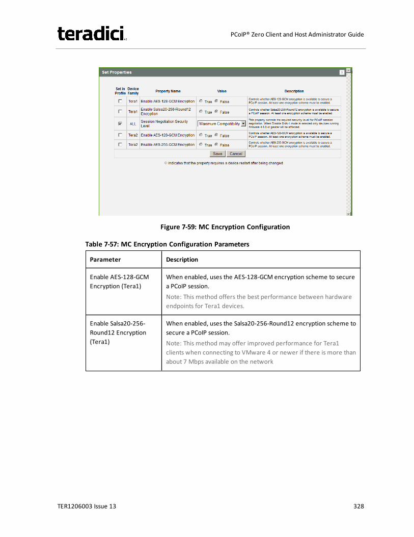
Figure 7-59: MC Encryption Configuration
Table 7-57: MC Encryption Configuration Parameters
Parameter Description
Enable AES-128-GCMEncryption (Tera1)
When enabled, uses the AES-128-GCM encryption scheme to securea PCoIP session.Note: This method offers the best performance between hardwareendpoints for Tera1 devices.
Enable Salsa20-256-Round12 Encryption(Tera1)
When enabled, uses the Salsa20-256-Round12 encryption scheme tosecure a PCoIP session.Note: This method may offer improved performance for Tera1clients when connecting to VMware 4 or newer if there is more thanabout 7 Mbps available on the network
TER1206003 Issue 13 328
PCoIP® Zero Client and Host Administrator Guide
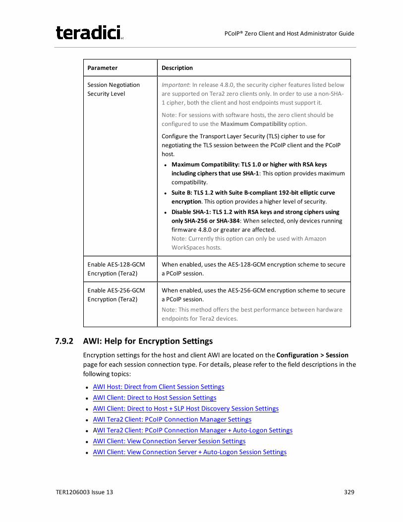
Parameter Description
Session NegotiationSecurity Level
Important: In release 4.8.0, the security cipher features listed beloware supported on Tera2 zero clients only. In order to use a non-SHA-1 cipher, both the client and host endpoints must support it.
Note: For sessions with software hosts, the zero client should beconfigured to use the Maximum Compatibility option.
Configure the Transport Layer Security (TLS) cipher to use fornegotiating the TLS session between the PCoIP client and the PCoIPhost.l Maximum Compatibility: TLS 1.0 or higher with RSA keys
including ciphers that use SHA-1: This option provides maximumcompatibility.
l Suite B: TLS 1.2 with Suite B-compliant 192-bit elliptic curveencryption. This option provides a higher level of security.
l Disable SHA-1: TLS 1.2 with RSA keys and strong ciphers usingonly SHA-256 or SHA-384: When selected, only devices runningfirmware 4.8.0 or greater are affected.Note: Currently this option can only be used with AmazonWorkSpaces hosts.
Enable AES-128-GCMEncryption (Tera2)
When enabled, uses the AES-128-GCM encryption scheme to securea PCoIP session.
Enable AES-256-GCMEncryption (Tera2)
When enabled, uses the AES-256-GCM encryption scheme to securea PCoIP session.Note: This method offers the best performance between hardwareendpoints for Tera2 devices.
7.9.2 AWI: Help for Encryption SettingsEncryption settings for the host and client AWI are located on the Configuration > Sessionpage for each session connection type. For details, please refer to the field descriptions in thefollowing topics:
l AWI Host: Direct from Client Session Settingsl AWI Client: Direct to Host Session Settingsl AWI Client: Direct to Host + SLP Host Discovery Session Settingsl AWI Tera2 Client: PCoIP Connection Manager Settingsl AWI Tera2 Client: PCoIP Connection Manager + Auto-Logon Settingsl AWI Client: View Connection Server Session Settingsl AWI Client: View Connection Server + Auto-Logon Session Settings
TER1206003 Issue 13 329
PCoIP® Zero Client and Host Administrator Guide
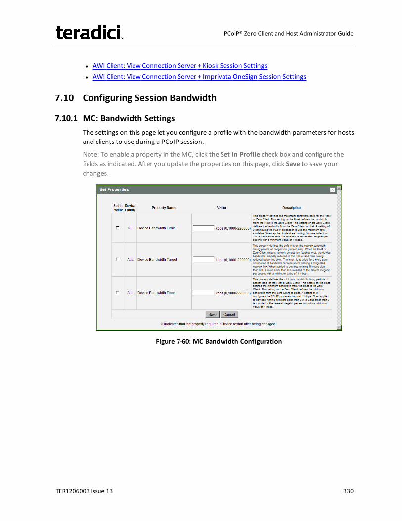
l AWI Client: View Connection Server + Kiosk Session Settingsl AWI Client: View Connection Server + Imprivata OneSign Session Settings
7.10 Configuring Session Bandwidth
7.10.1 MC: Bandwidth SettingsThe settings on this page let you configure a profile with the bandwidth parameters for hostsand clients to use during a PCoIP session.
Note: To enable a property in theMC, click the Set in Profile check box and configure thefields as indicated. After you update the properties on this page, click Save to save yourchanges.
Figure 7-60: MC Bandwidth Configuration
TER1206003 Issue 13 330
PCoIP® Zero Client and Host Administrator Guide
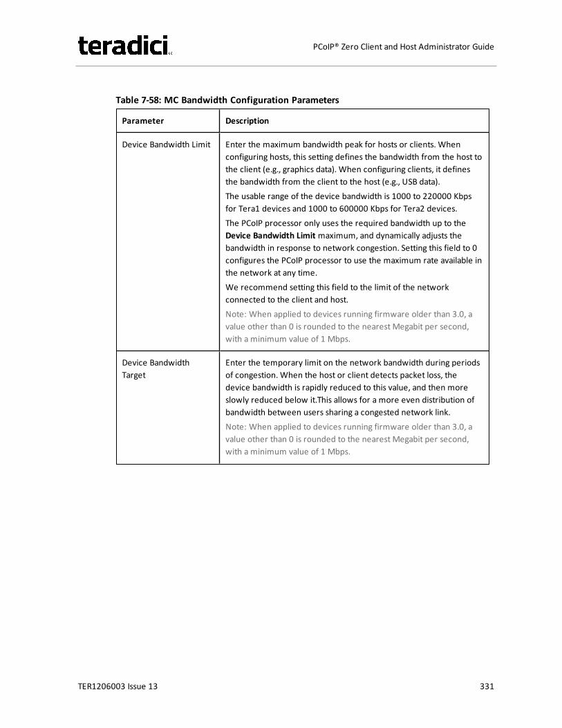
Table 7-58: MC Bandwidth Configuration Parameters
Parameter Description
Device Bandwidth Limit Enter the maximum bandwidth peak for hosts or clients. Whenconfiguring hosts, this setting defines the bandwidth from the host tothe client (e.g., graphics data). When configuring clients, it definesthe bandwidth from the client to the host (e.g., USB data).The usable range of the device bandwidth is 1000 to 220000 Kbpsfor Tera1 devices and 1000 to 600000 Kbps for Tera2 devices.The PCoIP processor only uses the required bandwidth up to theDevice Bandwidth Limit maximum, and dynamically adjusts thebandwidth in response to network congestion. Setting this field to 0configures the PCoIP processor to use the maximum rate available inthe network at any time.We recommend setting this field to the limit of the networkconnected to the client and host.Note: When applied to devices running firmware older than 3.0, avalue other than 0 is rounded to the nearest Megabit per second,with a minimum value of 1 Mbps.
Device BandwidthTarget
Enter the temporary limit on the network bandwidth during periodsof congestion. When the host or client detects packet loss, thedevice bandwidth is rapidly reduced to this value, and then moreslowly reduced below it.This allows for a more even distribution ofbandwidth between users sharing a congested network link.Note: When applied to devices running firmware older than 3.0, avalue other than 0 is rounded to the nearest Megabit per second,with a minimum value of 1 Mbps.
TER1206003 Issue 13 331
PCoIP® Zero Client and Host Administrator Guide
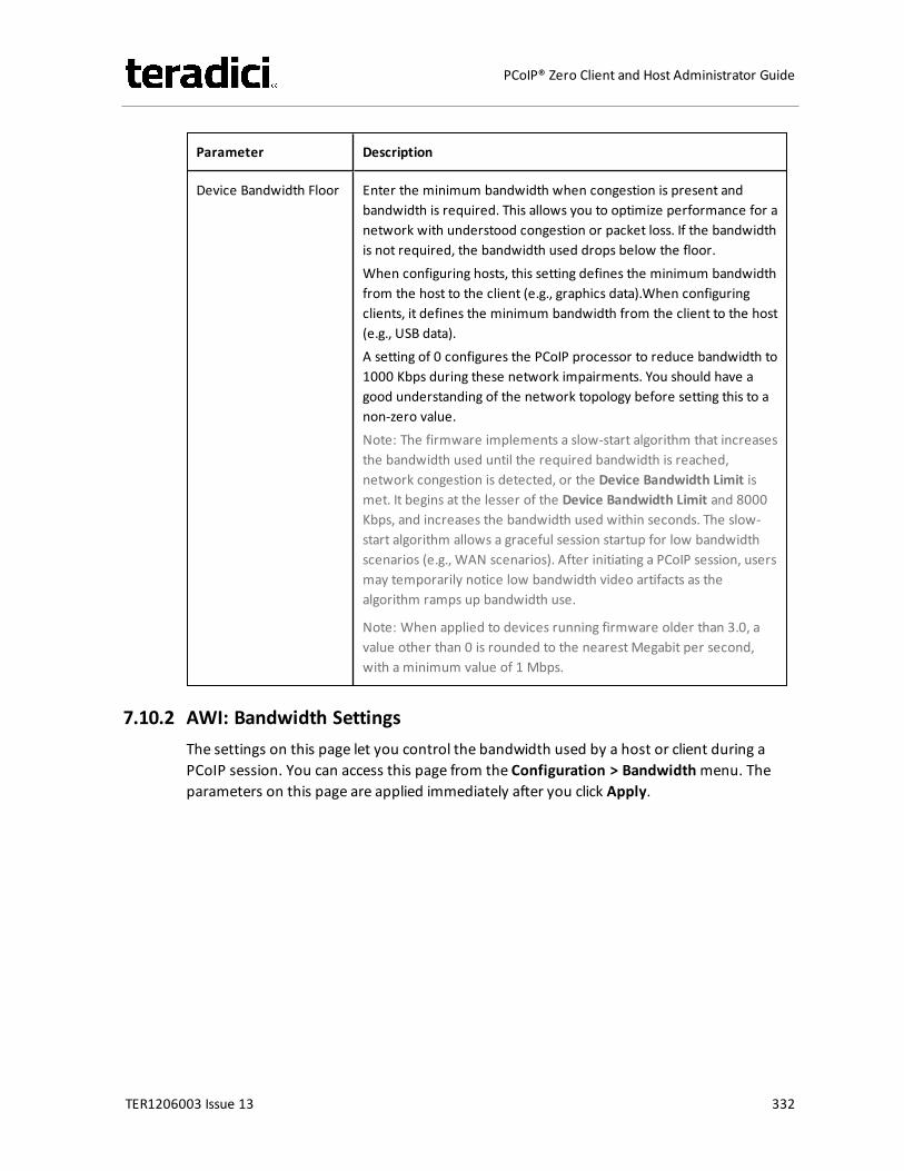
Parameter Description
Device Bandwidth Floor Enter the minimum bandwidth when congestion is present andbandwidth is required. This allows you to optimize performance for anetwork with understood congestion or packet loss. If the bandwidthis not required, the bandwidth used drops below the floor.When configuring hosts, this setting defines the minimum bandwidthfrom the host to the client (e.g., graphics data).When configuringclients, it defines the minimum bandwidth from the client to the host(e.g., USB data).A setting of 0 configures the PCoIP processor to reduce bandwidth to1000 Kbps during these network impairments. You should have agood understanding of the network topology before setting this to anon-zero value.Note: The firmware implements a slow-start algorithm that increasesthe bandwidth used until the required bandwidth is reached,network congestion is detected, or the Device Bandwidth Limit ismet. It begins at the lesser of the Device Bandwidth Limit and 8000Kbps, and increases the bandwidth used within seconds. The slow-start algorithm allows a graceful session startup for low bandwidthscenarios (e.g., WAN scenarios). After initiating a PCoIP session, usersmay temporarily notice low bandwidth video artifacts as thealgorithm ramps up bandwidth use.
Note: When applied to devices running firmware older than 3.0, avalue other than 0 is rounded to the nearest Megabit per second,with a minimum value of 1 Mbps.
7.10.2 AWI: Bandwidth SettingsThe settings on this page let you control the bandwidth used by a host or client during aPCoIP session. You can access this page from the Configuration > Bandwidthmenu. Theparameters on this page are applied immediately after you click Apply.
TER1206003 Issue 13 332
PCoIP® Zero Client and Host Administrator Guide
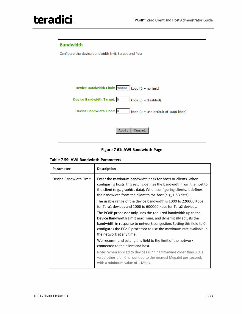
Figure 7-61: AWI Bandwidth Page
Table 7-59: AWI Bandwidth Parameters
Parameter Description
Device Bandwidth Limit Enter the maximum bandwidth peak for hosts or clients. Whenconfiguring hosts, this setting defines the bandwidth from the host tothe client (e.g., graphics data). When configuring clients, it definesthe bandwidth from the client to the host (e.g., USB data).The usable range of the device bandwidth is 1000 to 220000 Kbpsfor Tera1 devices and 1000 to 600000 Kbps for Tera2 devices.The PCoIP processor only uses the required bandwidth up to theDevice Bandwidth Limit maximum, and dynamically adjusts thebandwidth in response to network congestion. Setting this field to 0configures the PCoIP processor to use the maximum rate available inthe network at any time.We recommend setting this field to the limit of the networkconnected to the client and host.Note: When applied to devices running firmware older than 3.0, avalue other than 0 is rounded to the nearest Megabit per second,with a minimum value of 1 Mbps.
TER1206003 Issue 13 333
PCoIP® Zero Client and Host Administrator Guide
Parameter Description
Device BandwidthTarget
Enter the temporary limit on the network bandwidth during periodsof congestion. When the host or client detects packet loss, thedevice bandwidth is rapidly reduced to this value, and then moreslowly reduced below it.This allows for a more even distribution ofbandwidth between users sharing a congested network link.Note: When applied to devices running firmware older than 3.0, avalue other than 0 is rounded to the nearest Megabit per second,with a minimum value of 1 Mbps.
Device Bandwidth Floor Enter the minimum bandwidth when congestion is present andbandwidth is required. This allows you to optimize performance for anetwork with understood congestion or packet loss. If the bandwidthis not required, the bandwidth used drops below the floor.When configuring hosts, this setting defines the minimum bandwidthfrom the host to the client (e.g., graphics data).When configuringclients, it defines the minimum bandwidth from the client to the host(e.g., USB data).A setting of 0 configures the PCoIP processor to reduce bandwidth to1000 Kbps during these network impairments. You should have agood understanding of the network topology before setting this to anon-zero value.Note: The firmware implements a slow-start algorithm that increasesthe bandwidth used until the required bandwidth is reached,network congestion is detected, or the Device Bandwidth Limit ismet. It begins at the lesser of the Device Bandwidth Limit and 8000Kbps, and increases the bandwidth used within seconds. The slow-start algorithm allows a graceful session startup for low bandwidthscenarios (e.g., WAN scenarios). After initiating a PCoIP session, usersmay temporarily notice low bandwidth video artifacts as thealgorithm ramps up bandwidth use.
Note: When applied to devices running firmware older than 3.0, avalue other than 0 is rounded to the nearest Megabit per second,with a minimum value of 1 Mbps.
7.11 Configuring the Language
7.11.1 MC: Language SettingsThe settings on this page let you configure a profile with the language to use in the OSD userinterface.
TER1206003 Issue 13 334
PCoIP® Zero Client and Host Administrator Guide
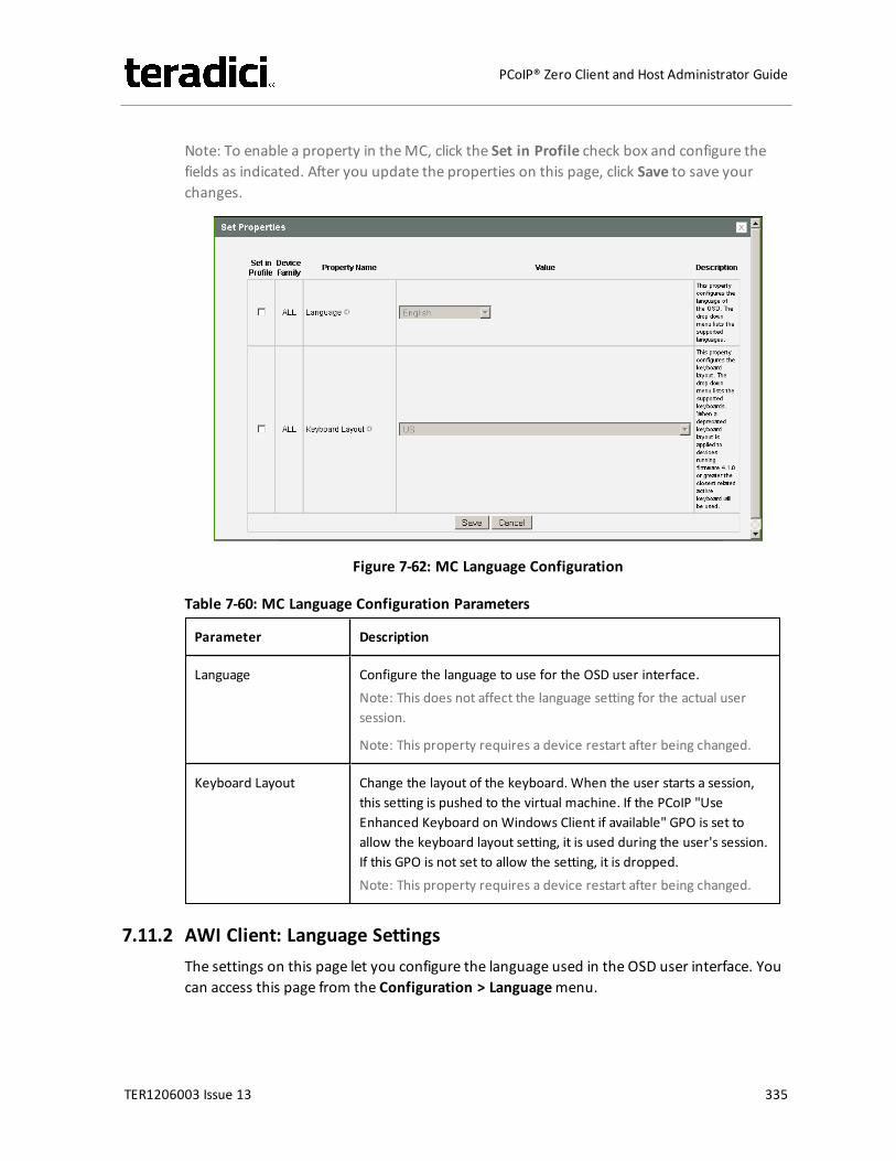
Note: To enable a property in theMC, click the Set in Profile check box and configure thefields as indicated. After you update the properties on this page, click Save to save yourchanges.
Figure 7-62: MC Language Configuration
Table 7-60: MC Language Configuration Parameters
Parameter Description
Language Configure the language to use for the OSD user interface.Note: This does not affect the language setting for the actual usersession.
Note: This property requires a device restart after being changed.
Keyboard Layout Change the layout of the keyboard. When the user starts a session,this setting is pushed to the virtual machine. If the PCoIP "UseEnhanced Keyboard on Windows Client if available" GPO is set toallow the keyboard layout setting, it is used during the user's session.If this GPO is not set to allow the setting, it is dropped.Note: This property requires a device restart after being changed.
7.11.2 AWI Client: Language SettingsThe settings on this page let you configure the language used in the OSD user interface. Youcan access this page from the Configuration > Languagemenu.
TER1206003 Issue 13 335
PCoIP® Zero Client and Host Administrator Guide
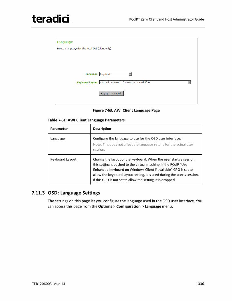
Figure 7-63: AWI Client Language Page
Table 7-61: AWI Client Language Parameters
Parameter Description
Language Configure the language to use for the OSD user interface.Note: This does not affect the language setting for the actual usersession.
Keyboard Layout Change the layout of the keyboard. When the user starts a session,this setting is pushed to the virtual machine. If the PCoIP "UseEnhanced Keyboard on Windows Client if available" GPO is set toallow the keyboard layout setting, it is used during the user's session.If this GPO is not set to allow the setting, it is dropped.
7.11.3 OSD: Language SettingsThe settings on this page let you configure the language used in the OSD user interface. Youcan access this page from theOptions > Configuration > Languagemenu.
TER1206003 Issue 13 336
PCoIP® Zero Client and Host Administrator Guide
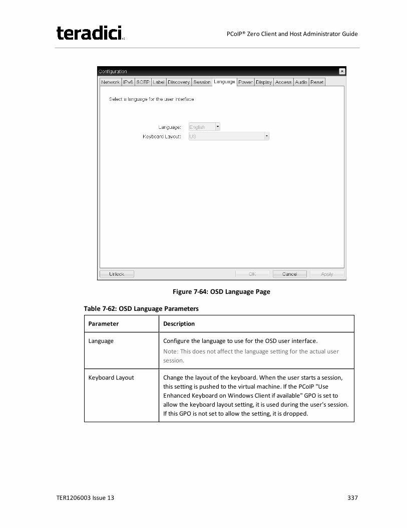
Figure 7-64: OSD Language Page
Table 7-62: OSD Language Parameters
Parameter Description
Language Configure the language to use for the OSD user interface.Note: This does not affect the language setting for the actual usersession.
Keyboard Layout Change the layout of the keyboard. When the user starts a session,this setting is pushed to the virtual machine. If the PCoIP "UseEnhanced Keyboard on Windows Client if available" GPO is set toallow the keyboard layout setting, it is used during the user's session.If this GPO is not set to allow the setting, it is dropped.
TER1206003 Issue 13 337
PCoIP® Zero Client and Host Administrator Guide
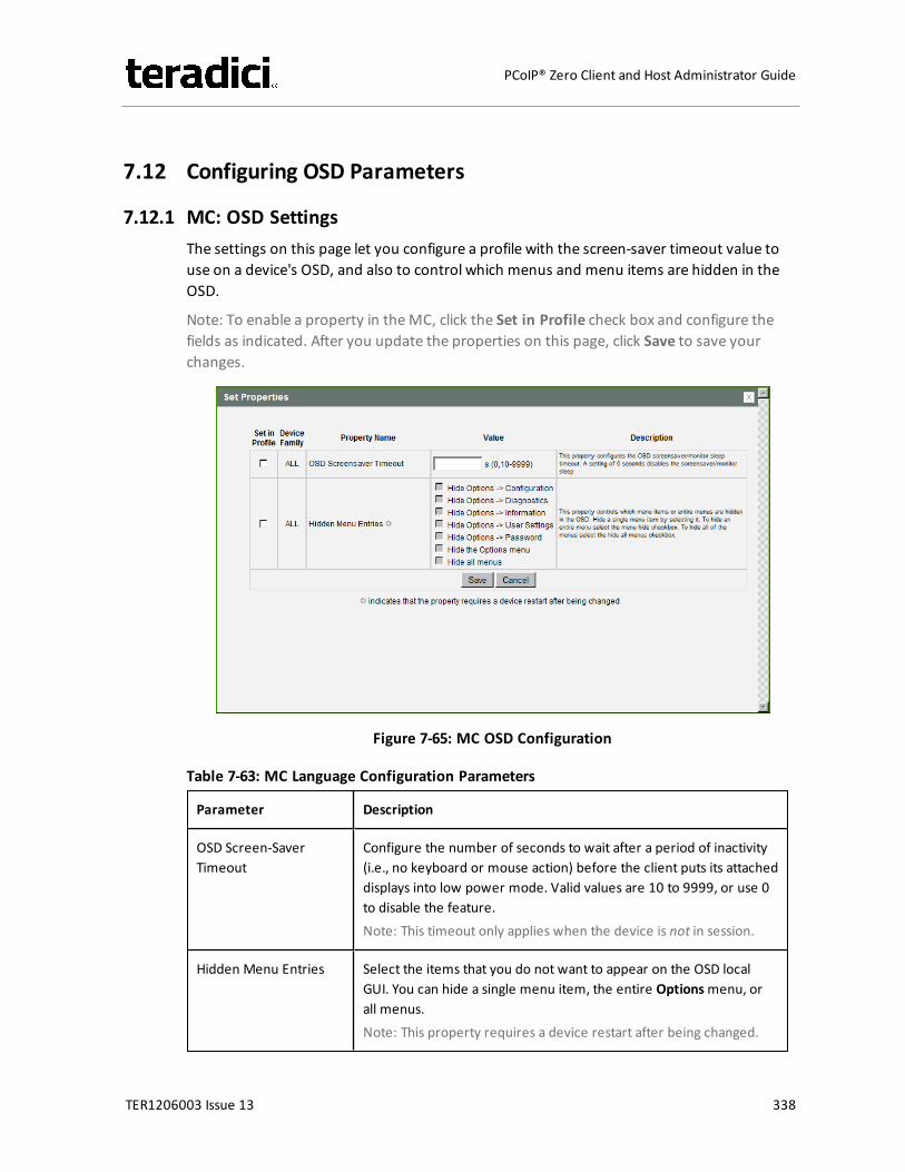
7.12 Configuring OSD Parameters
7.12.1 MC: OSD SettingsThe settings on this page let you configure a profile with the screen-saver timeout value touse on a device's OSD, and also to control which menus and menu items are hidden in theOSD.
Note: To enable a property in theMC, click the Set in Profile check box and configure thefields as indicated. After you update the properties on this page, click Save to save yourchanges.
Figure 7-65: MC OSD Configuration
Table 7-63: MC Language Configuration Parameters
Parameter Description
OSD Screen-SaverTimeout
Configure the number of seconds to wait after a period of inactivity(i.e., no keyboard or mouse action) before the client puts its attacheddisplays into low power mode. Valid values are 10 to 9999, or use 0to disable the feature.Note: This timeout only applies when the device is not in session.
Hidden Menu Entries Select the items that you do not want to appear on the OSD localGUI. You can hide a single menu item, the entire Optionsmenu, orall menus.Note: This property requires a device restart after being changed.
TER1206003 Issue 13 338
PCoIP® Zero Client and Host Administrator Guide
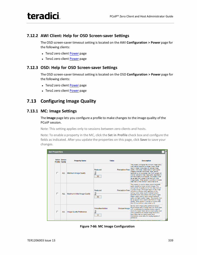
7.12.2 AWI Client: Help for OSD Screen-saver SettingsThe OSD screen-saver timeout setting is located on the AWI Configuration > Power page forthe following clients:
l Tera2 zero client Power pagel Tera1 zero client Power page
7.12.3 OSD: Help for OSD Screen-saver SettingsThe OSD screen-saver timeout setting is located on the OSD Configuration > Power page forthe following clients:
l Tera2 zero client Power pagel Tera1 zero client Power page
7.13 Configuring Image Quality
7.13.1 MC: Image SettingsThe Image page lets you configure a profile to make changes to the image quality of thePCoIP session.
Note: This setting applies only to sessions between zero clients and hosts.
Note: To enable a property in theMC, click the Set in Profile check box and configure thefields as indicated. After you update the properties on this page, click Save to save yourchanges.
Figure 7-66: MC Image Configuration
TER1206003 Issue 13 339
PCoIP® Zero Client and Host Administrator Guide

Table 7-64: MC Image Configuration Parameters
Parameter Description
Minimum Image Quality Lets you compromise between image quality and frame rate whennetwork bandwidth is limited. Some use cases may require lower-quality images at a higher frame rate while others need higher-quality images at a lower frame rate.In environments where the network bandwidth is constrained, movethe slider towards Reduced to allow higher frame rates. Move theslider towards Perception-Free to allow for higher image quality.When network bandwidth is not constrained, the PCoIP systemmaintains perception-free quality regardless of the Minimum ImageQuality parameter.Note: The Maximum Initial Image Qualitymust be greater than orequal to the Minimum Image Quality.
Maximum Initial ImageQuality
Move the slider towards Reduced to reduce the network bandwidthpeaks caused by screen content changes, but produce lower qualityimages. Move the slider towards Perception-Free to produce higherquality images but also higher bandwidth peaks.This parameter limits the initial quality on the first display frame of ascreen change. Unchanged regions of the image are built to alossless state regardless of this parameter.Note: The Maximum Initial Image Qualitymust be greater than orequal to the Minimum Image Quality.
Image QualityPreference
Move the slider towards Smoother Motion to result in a higherframe rate at a lower quality level. Move the slider towards SharperImage to result in a lower frame rate at a higher quality level. Therange is from 0 to 100 in steps of 5.Note: This setting does not work in PCoIP sessions with VMwareHorizon virtual desktops running release 5.0 or earlier.
TER1206003 Issue 13 340
PCoIP® Zero Client and Host Administrator Guide
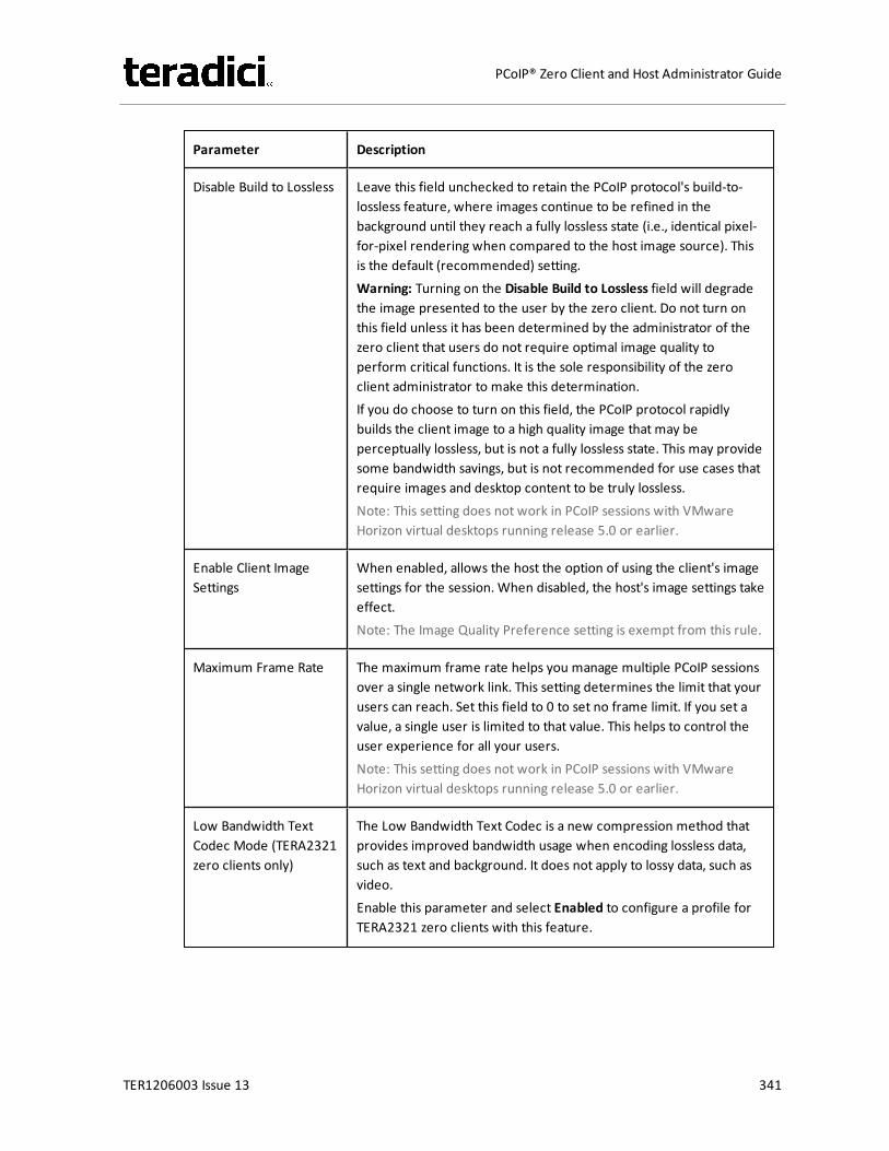
Parameter Description
Disable Build to Lossless Leave this field unchecked to retain the PCoIP protocol's build-to-lossless feature, where images continue to be refined in thebackground until they reach a fully lossless state (i.e., identical pixel-for-pixel rendering when compared to the host image source). Thisis the default (recommended) setting.Warning: Turning on the Disable Build to Lossless field will degradethe image presented to the user by the zero client. Do not turn onthis field unless it has been determined by the administrator of thezero client that users do not require optimal image quality toperform critical functions. It is the sole responsibility of the zeroclient administrator to make this determination.If you do choose to turn on this field, the PCoIP protocol rapidlybuilds the client image to a high quality image that may beperceptually lossless, but is not a fully lossless state. This may providesome bandwidth savings, but is not recommended for use cases thatrequire images and desktop content to be truly lossless.Note: This setting does not work in PCoIP sessions with VMwareHorizon virtual desktops running release 5.0 or earlier.
Enable Client ImageSettings
When enabled, allows the host the option of using the client's imagesettings for the session. When disabled, the host's image settings takeeffect.Note: The Image Quality Preference setting is exempt from this rule.
Maximum Frame Rate The maximum frame rate helps you manage multiple PCoIP sessionsover a single network link. This setting determines the limit that yourusers can reach. Set this field to 0 to set no frame limit. If you set avalue, a single user is limited to that value. This helps to control theuser experience for all your users.Note: This setting does not work in PCoIP sessions with VMwareHorizon virtual desktops running release 5.0 or earlier.
Low Bandwidth TextCodec Mode (TERA2321zero clients only)
The Low Bandwidth Text Codec is a new compression method thatprovides improved bandwidth usage when encoding lossless data,such as text and background. It does not apply to lossy data, such asvideo.Enable this parameter and select Enabled to configure a profile forTERA2321 zero clients with this feature.
TER1206003 Issue 13 341
PCoIP® Zero Client and Host Administrator Guide
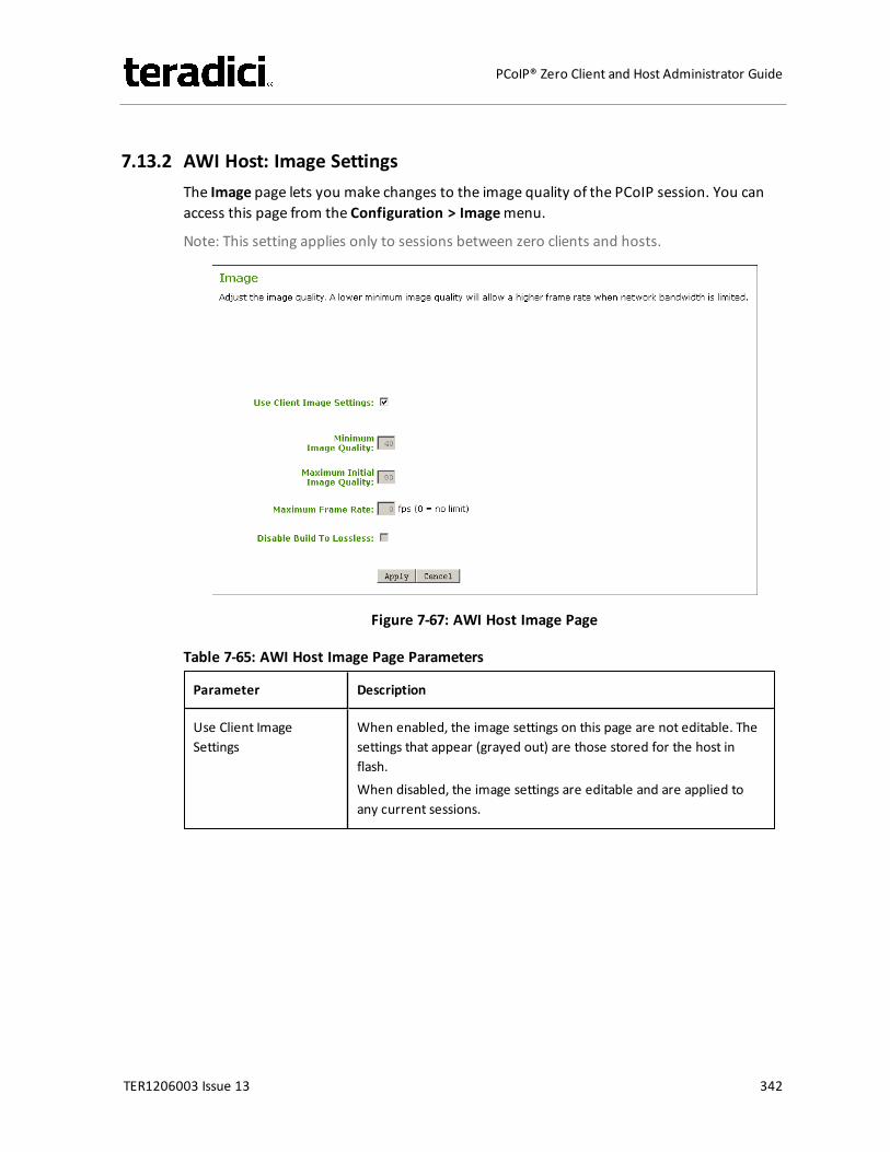
7.13.2 AWI Host: Image SettingsThe Image page lets you make changes to the image quality of the PCoIP session. You canaccess this page from the Configuration > Imagemenu.
Note: This setting applies only to sessions between zero clients and hosts.
Figure 7-67: AWI Host Image Page
Table 7-65: AWI Host Image Page Parameters
Parameter Description
Use Client ImageSettings
When enabled, the image settings on this page are not editable. Thesettings that appear (grayed out) are those stored for the host inflash.When disabled, the image settings are editable and are applied toany current sessions.
TER1206003 Issue 13 342
PCoIP® Zero Client and Host Administrator Guide
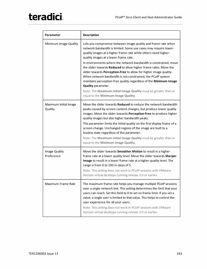
Parameter Description
Minimum Image Quality Lets you compromise between image quality and frame rate whennetwork bandwidth is limited. Some use cases may require lower-quality images at a higher frame rate while others need higher-quality images at a lower frame rate.In environments where the network bandwidth is constrained, movethe slider towards Reduced to allow higher frame rates. Move theslider towards Perception-Free to allow for higher image quality.When network bandwidth is not constrained, the PCoIP systemmaintains perception-free quality regardless of the Minimum ImageQuality parameter.Note: The Maximum Initial Image Qualitymust be greater than orequal to the Minimum Image Quality.
Maximum Initial ImageQuality
Move the slider towards Reduced to reduce the network bandwidthpeaks caused by screen content changes, but produce lower qualityimages. Move the slider towards Perception-Free to produce higherquality images but also higher bandwidth peaks.This parameter limits the initial quality on the first display frame of ascreen change. Unchanged regions of the image are built to alossless state regardless of this parameter.Note: The Maximum Initial Image Qualitymust be greater than orequal to the Minimum Image Quality.
Image QualityPreference
Move the slider towards Smoother Motion to result in a higherframe rate at a lower quality level. Move the slider towards SharperImage to result in a lower frame rate at a higher quality level. Therange is from 0 to 100 in steps of 5.Note: This setting does not work in PCoIP sessions with VMwareHorizon virtual desktops running release 5.0 or earlier.
Maximum Frame Rate The maximum frame rate helps you manage multiple PCoIP sessionsover a single network link. This setting determines the limit that yourusers can reach. Set this field to 0 to set no frame limit. If you set avalue, a single user is limited to that value. This helps to control theuser experience for all your users.Note: This setting does not work in PCoIP sessions with VMwareHorizon virtual desktops running release 5.0 or earlier.
TER1206003 Issue 13 343
PCoIP® Zero Client and Host Administrator Guide

Parameter Description
Disable Build to Lossless Leave this field unchecked to retain the PCoIP protocol's build-to-lossless feature, where images continue to be refined in thebackground until they reach a fully lossless state (i.e., identical pixel-for-pixel rendering when compared to the host image source). Thisis the default (recommended) setting.Warning: Turning on the Disable Build to Lossless field will degradethe image presented to the user by the zero client. Do not turn onthis field unless it has been determined by the administrator of thezero client that users do not require optimal image quality toperform critical functions. It is the sole responsibility of the zeroclient administrator to make this determination.If you do choose to turn on this field, the PCoIP protocol rapidlybuilds the client image to a high quality image that may beperceptually lossless, but is not a fully lossless state. This may providesome bandwidth savings, but is not recommended for use cases thatrequire images and desktop content to be truly lossless.Note: This setting does not work in PCoIP sessions with VMwareHorizon virtual desktops running release 5.0 or earlier.
7.13.3 AWI Tera2 Client: Image SettingsThe Image page lets you make changes to the image quality of the PCoIP session. You canaccess this page from the Configuration > Imagemenu.
Note: This setting applies only to sessions between zero clients and hosts.
TER1206003 Issue 13 344
PCoIP® Zero Client and Host Administrator Guide
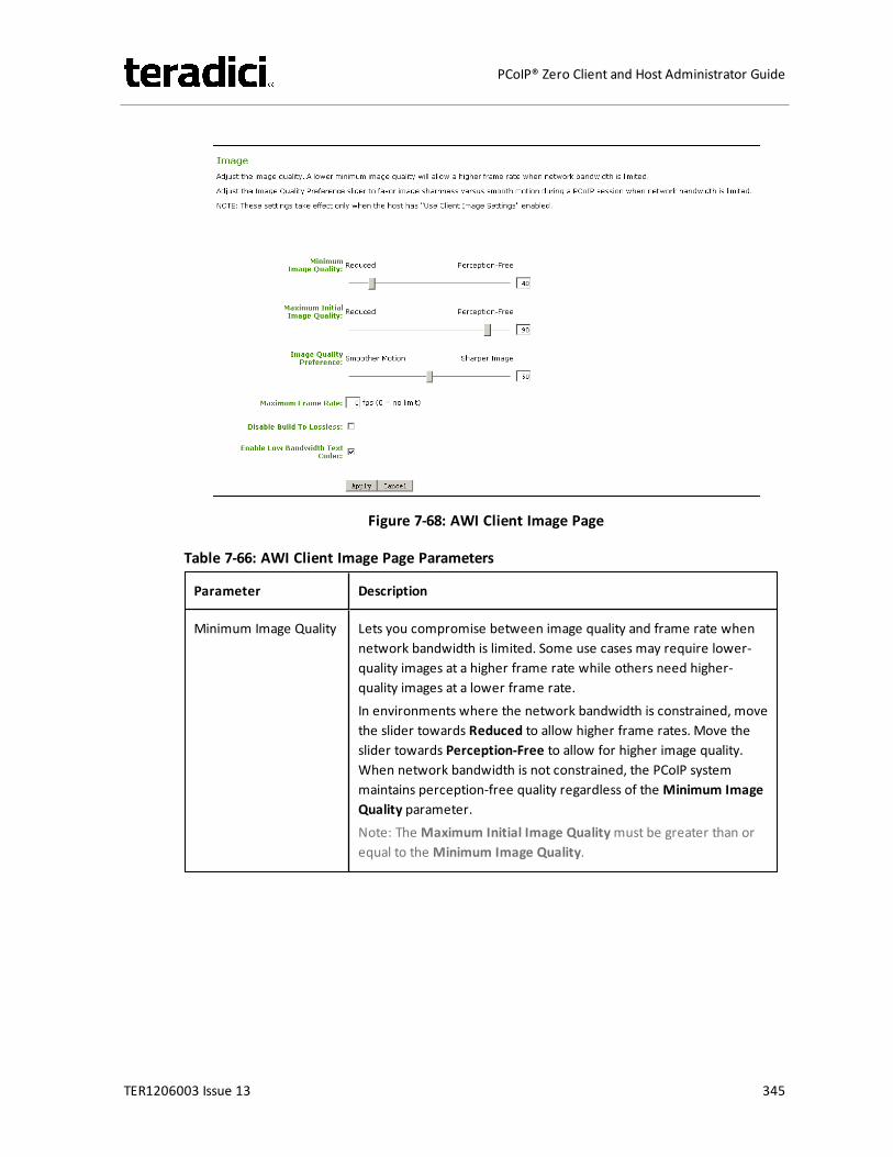
Figure 7-68: AWI Client Image Page
Table 7-66: AWI Client Image Page Parameters
Parameter Description
Minimum Image Quality Lets you compromise between image quality and frame rate whennetwork bandwidth is limited. Some use cases may require lower-quality images at a higher frame rate while others need higher-quality images at a lower frame rate.In environments where the network bandwidth is constrained, movethe slider towards Reduced to allow higher frame rates. Move theslider towards Perception-Free to allow for higher image quality.When network bandwidth is not constrained, the PCoIP systemmaintains perception-free quality regardless of the Minimum ImageQuality parameter.Note: The Maximum Initial Image Qualitymust be greater than orequal to the Minimum Image Quality.
TER1206003 Issue 13 345
PCoIP® Zero Client and Host Administrator Guide
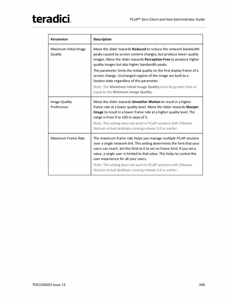
Parameter Description
Maximum Initial ImageQuality
Move the slider towards Reduced to reduce the network bandwidthpeaks caused by screen content changes, but produce lower qualityimages. Move the slider towards Perception-Free to produce higherquality images but also higher bandwidth peaks.This parameter limits the initial quality on the first display frame of ascreen change. Unchanged regions of the image are built to alossless state regardless of this parameter.Note: The Maximum Initial Image Qualitymust be greater than orequal to the Minimum Image Quality.
Image QualityPreference
Move the slider towards Smoother Motion to result in a higherframe rate at a lower quality level. Move the slider towards SharperImage to result in a lower frame rate at a higher quality level. Therange is from 0 to 100 in steps of 5.Note: This setting does not work in PCoIP sessions with VMwareHorizon virtual desktops running release 5.0 or earlier.
Maximum Frame Rate The maximum frame rate helps you manage multiple PCoIP sessionsover a single network link. This setting determines the limit that yourusers can reach. Set this field to 0 to set no frame limit. If you set avalue, a single user is limited to that value. This helps to control theuser experience for all your users.Note: This setting does not work in PCoIP sessions with VMwareHorizon virtual desktops running release 5.0 or earlier.
TER1206003 Issue 13 346
PCoIP® Zero Client and Host Administrator Guide
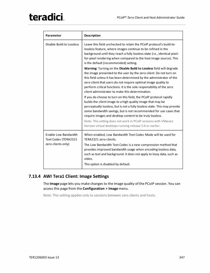
Parameter Description
Disable Build to Lossless Leave this field unchecked to retain the PCoIP protocol's build-to-lossless feature, where images continue to be refined in thebackground until they reach a fully lossless state (i.e., identical pixel-for-pixel rendering when compared to the host image source). Thisis the default (recommended) setting.Warning: Turning on the Disable Build to Lossless field will degradethe image presented to the user by the zero client. Do not turn onthis field unless it has been determined by the administrator of thezero client that users do not require optimal image quality toperform critical functions. It is the sole responsibility of the zeroclient administrator to make this determination.If you do choose to turn on this field, the PCoIP protocol rapidlybuilds the client image to a high quality image that may beperceptually lossless, but is not a fully lossless state. This may providesome bandwidth savings, but is not recommended for use cases thatrequire images and desktop content to be truly lossless.Note: This setting does not work in PCoIP sessions with VMwareHorizon virtual desktops running release 5.0 or earlier.
Enable Low BandwidthText Codec (TERA2321zero clients only)
When enabled, Low Bandwidth Text Codec Mode will be used forTERA2321 zero clients.The Low Bandwidth Text Codec is a new compression method thatprovides improved bandwidth usage when encoding lossless data,such as text and background. It does not apply to lossy data, such asvideo.This option is disabled by default.
7.13.4 AWI Tera1 Client: Image SettingsThe Image page lets you make changes to the image quality of the PCoIP session. You canaccess this page from the Configuration > Imagemenu.
Note: This setting applies only to sessions between zero clients and hosts.
TER1206003 Issue 13 347
PCoIP® Zero Client and Host Administrator Guide
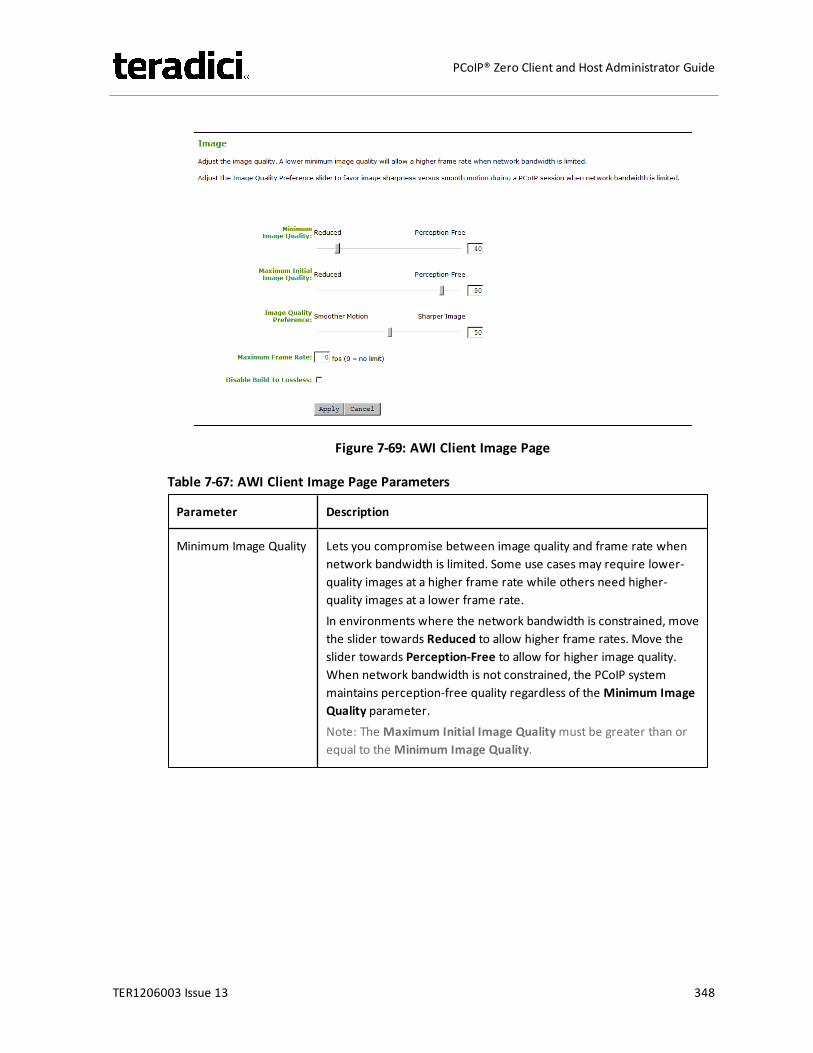
Figure 7-69: AWI Client Image Page
Table 7-67: AWI Client Image Page Parameters
Parameter Description
Minimum Image Quality Lets you compromise between image quality and frame rate whennetwork bandwidth is limited. Some use cases may require lower-quality images at a higher frame rate while others need higher-quality images at a lower frame rate.In environments where the network bandwidth is constrained, movethe slider towards Reduced to allow higher frame rates. Move theslider towards Perception-Free to allow for higher image quality.When network bandwidth is not constrained, the PCoIP systemmaintains perception-free quality regardless of the Minimum ImageQuality parameter.Note: The Maximum Initial Image Qualitymust be greater than orequal to the Minimum Image Quality.
TER1206003 Issue 13 348
PCoIP® Zero Client and Host Administrator Guide

Parameter Description
Maximum Initial ImageQuality
Move the slider towards Reduced to reduce the network bandwidthpeaks caused by screen content changes, but produce lower qualityimages. Move the slider towards Perception-Free to produce higherquality images but also higher bandwidth peaks.This parameter limits the initial quality on the first display frame of ascreen change. Unchanged regions of the image are built to alossless state regardless of this parameter.Note: The Maximum Initial Image Qualitymust be greater than orequal to the Minimum Image Quality.
Image QualityPreference
Move the slider towards Smoother Motion to result in a higherframe rate at a lower quality level. Move the slider towards SharperImage to result in a lower frame rate at a higher quality level. Therange is from 0 to 100 in steps of 5.Note: This setting does not work in PCoIP sessions with VMwareHorizon virtual desktops running release 5.0 or earlier.
Maximum Frame Rate The maximum frame rate helps you manage multiple PCoIP sessionsover a single network link. This setting determines the limit that yourusers can reach. Set this field to 0 to set no frame limit. If you set avalue, a single user is limited to that value. This helps to control theuser experience for all your users.Note: This setting does not work in PCoIP sessions with VMwareHorizon virtual desktops running release 5.0 or earlier.
TER1206003 Issue 13 349
PCoIP® Zero Client and Host Administrator Guide

Parameter Description
Disable Build to Lossless Leave this field unchecked to retain the PCoIP protocol's build-to-lossless feature, where images continue to be refined in thebackground until they reach a fully lossless state (i.e., identical pixel-for-pixel rendering when compared to the host image source). Thisis the default (recommended) setting.Warning: Turning on the Disable Build to Lossless field will degradethe image presented to the user by the zero client. Do not turn onthis field unless it has been determined by the administrator of thezero client that users do not require optimal image quality toperform critical functions. It is the sole responsibility of the zeroclient administrator to make this determination.If you do choose to turn on this field, the PCoIP protocol rapidlybuilds the client image to a high quality image that may beperceptually lossless, but is not a fully lossless state. This may providesome bandwidth savings, but is not recommended for use cases thatrequire images and desktop content to be truly lossless.Note: This setting does not work in PCoIP sessions with VMwareHorizon virtual desktops running release 5.0 or earlier.
7.13.5 OSD: Image SettingsThe Image page lets you make changes to the image quality of the PCoIP session. You canaccess this page from theOptions > User Settings > Imagemenu.
Note: This setting applies only to sessions between zero clients and hosts.
TER1206003 Issue 13 350
PCoIP® Zero Client and Host Administrator Guide
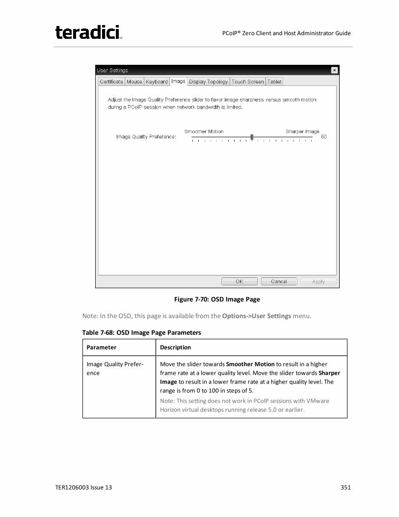
Figure 7-70: OSD Image Page
Note: In the OSD, this page is available from theOptions->User Settingsmenu.
Table 7-68: OSD Image Page Parameters
Parameter Description
Image Quality Prefer-ence
Move the slider towards Smoother Motion to result in a higherframe rate at a lower quality level. Move the slider towards SharperImage to result in a lower frame rate at a higher quality level. Therange is from 0 to 100 in steps of 5.Note: This setting does not work in PCoIP sessions with VMwareHorizon virtual desktops running release 5.0 or earlier.
TER1206003 Issue 13 351
PCoIP® Zero Client and Host Administrator Guide
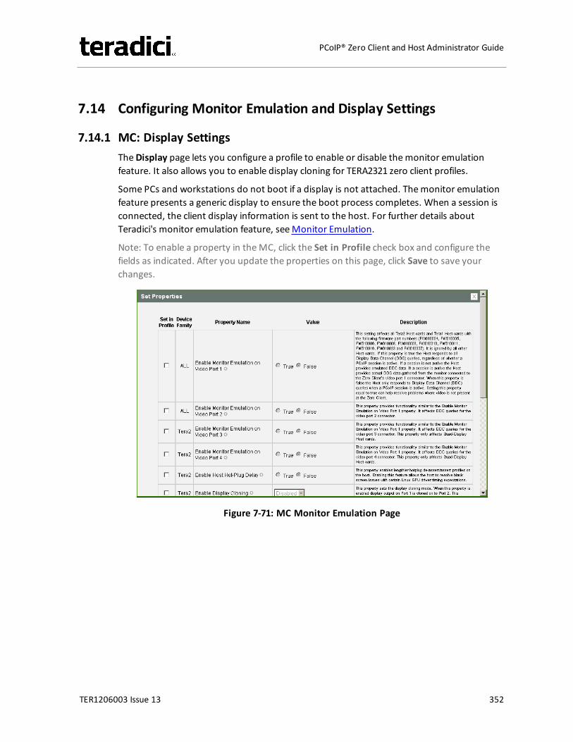
7.14 Configuring Monitor Emulation and Display Settings
7.14.1 MC: Display SettingsTheDisplay page lets you configure a profile to enable or disable themonitor emulationfeature. It also allows you to enable display cloning for TERA2321 zero client profiles.
Some PCs and workstations do not boot if a display is not attached. Themonitor emulationfeature presents a generic display to ensure the boot process completes. When a session isconnected, the client display information is sent to the host. For further details aboutTeradici's monitor emulation feature, seeMonitor Emulation.
Note: To enable a property in theMC, click the Set in Profile check box and configure thefields as indicated. After you update the properties on this page, click Save to save yourchanges.
Figure 7-71: MC Monitor Emulation Page
TER1206003 Issue 13 352
PCoIP® Zero Client and Host Administrator Guide
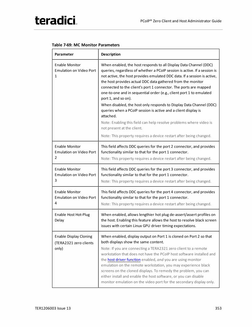
Table 7-69: MC Monitor Parameters
Parameter Description
Enable MonitorEmulation on Video Port1
When enabled, the host responds to all Display Data Channel (DDC)queries, regardless of whether a PCoIP session is active. If a session isnot active, the host provides emulated DDC data. If a session is active,the host provides actual DDC data gathered from the monitorconnected to the client's port 1 connector. The ports are mappedone-to-one and in sequential order (e.g., client port 1 to emulatedport 1, and so on).When disabled, the host only responds to Display Data Channel (DDC)queries when a PCoIP session is active and a client display isattached.Note: Enabling this field can help resolve problems where video isnot present at the client.
Note: This property requires a device restart after being changed.
Enable MonitorEmulation on Video Port2
This field affects DDC queries for the port 2 connector, and providesfunctionality similar to that for the port 1 connector.Note: This property requires a device restart after being changed.
Enable MonitorEmulation on Video Port3
This field affects DDC queries for the port 3 connector, and providesfunctionality similar to that for the port 1 connector.Note: This property requires a device restart after being changed.
Enable MonitorEmulation on Video Port4
This field affects DDC queries for the port 4 connector, and providesfunctionality similar to that for the port 1 connector.Note: This property requires a device restart after being changed.
Enable Host Hot-PlugDelay
When enabled, allows lengthier hot plug de-assert/assert profiles onthe host. Enabling this feature allows the host to resolve black screenissues with certain Linux GPU driver timing expectations.
Enable Display Cloning(TERA2321 zero clientsonly)
When enabled, display output on Port 1 is cloned on Port 2 so thatboth displays show the same content.Note: If you are connecting a TERA2321 zero client to a remoteworkstation that does not have the PCoIP host software installed andthe host driver function enabled, and you are using monitoremulation on the remote workstation, you may experience blackscreens on the cloned displays. To remedy the problem, you caneither install and enable the host software, or you can disablemonitor emulation on the video port for the secondary display only.
TER1206003 Issue 13 353
PCoIP® Zero Client and Host Administrator Guide
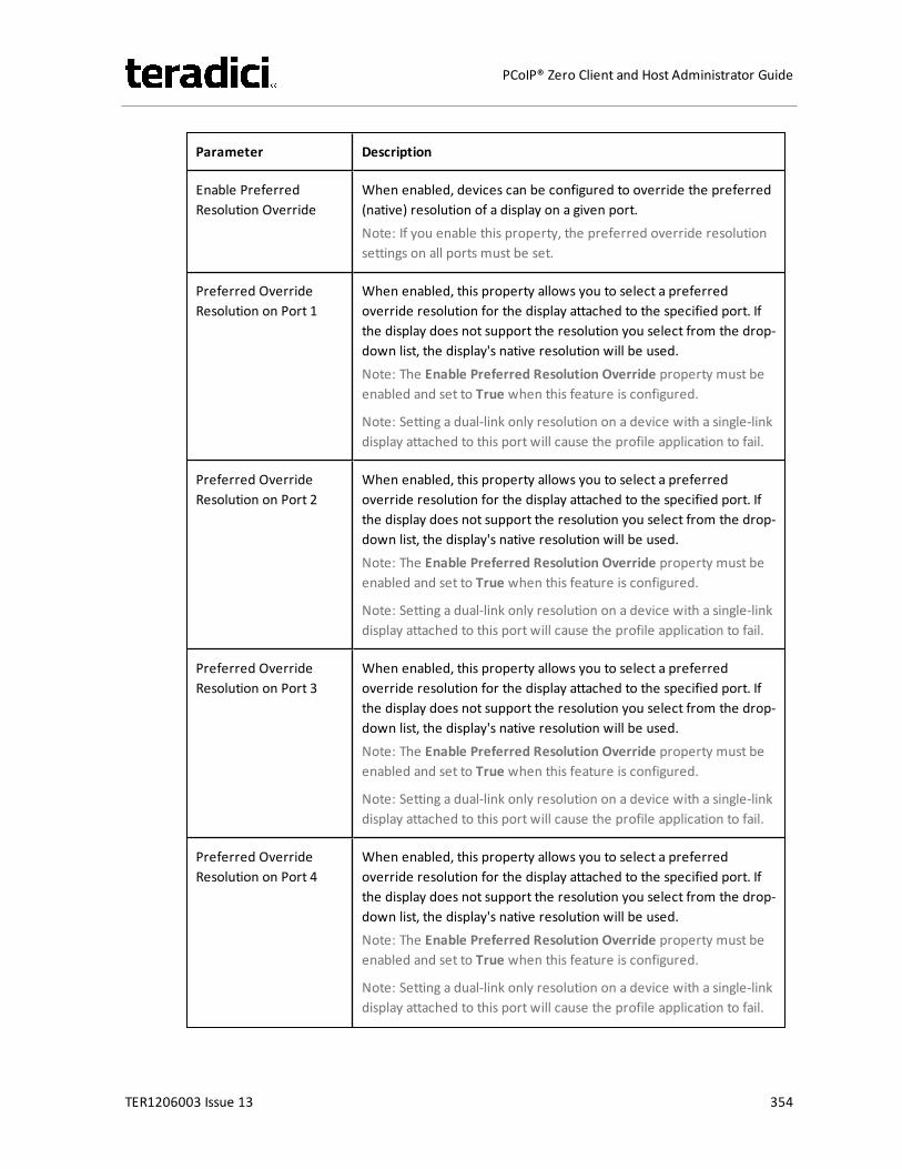
Parameter Description
Enable PreferredResolution Override
When enabled, devices can be configured to override the preferred(native) resolution of a display on a given port.Note: If you enable this property, the preferred override resolutionsettings on all ports must be set.
Preferred OverrideResolution on Port 1
When enabled, this property allows you to select a preferredoverride resolution for the display attached to the specified port. Ifthe display does not support the resolution you select from the drop-down list, the display's native resolution will be used.Note: The Enable Preferred Resolution Override property must beenabled and set to True when this feature is configured.
Note: Setting a dual-link only resolution on a device with a single-linkdisplay attached to this port will cause the profile application to fail.
Preferred OverrideResolution on Port 2
When enabled, this property allows you to select a preferredoverride resolution for the display attached to the specified port. Ifthe display does not support the resolution you select from the drop-down list, the display's native resolution will be used.Note: The Enable Preferred Resolution Override property must beenabled and set to True when this feature is configured.
Note: Setting a dual-link only resolution on a device with a single-linkdisplay attached to this port will cause the profile application to fail.
Preferred OverrideResolution on Port 3
When enabled, this property allows you to select a preferredoverride resolution for the display attached to the specified port. Ifthe display does not support the resolution you select from the drop-down list, the display's native resolution will be used.Note: The Enable Preferred Resolution Override property must beenabled and set to True when this feature is configured.
Note: Setting a dual-link only resolution on a device with a single-linkdisplay attached to this port will cause the profile application to fail.
Preferred OverrideResolution on Port 4
When enabled, this property allows you to select a preferredoverride resolution for the display attached to the specified port. Ifthe display does not support the resolution you select from the drop-down list, the display's native resolution will be used.Note: The Enable Preferred Resolution Override property must beenabled and set to True when this feature is configured.
Note: Setting a dual-link only resolution on a device with a single-linkdisplay attached to this port will cause the profile application to fail.
TER1206003 Issue 13 354
PCoIP® Zero Client and Host Administrator Guide
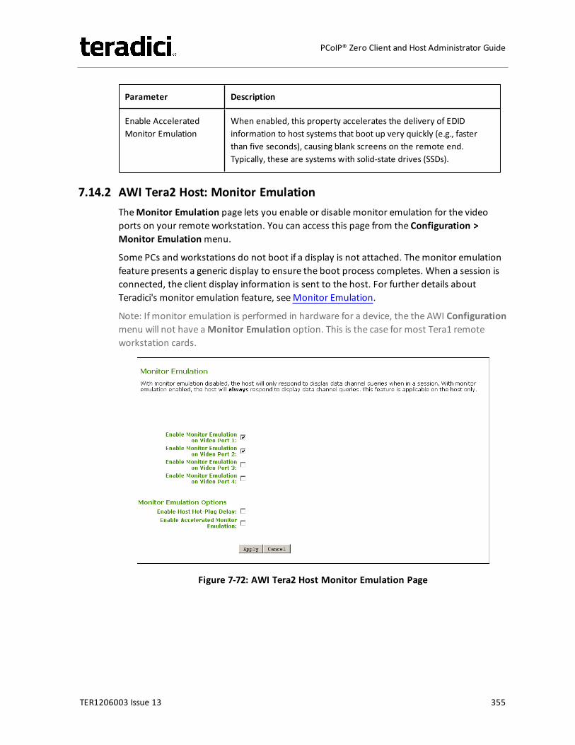
Parameter Description
Enable AcceleratedMonitor Emulation
When enabled, this property accelerates the delivery of EDIDinformation to host systems that boot up very quickly (e.g., fasterthan five seconds), causing blank screens on the remote end.Typically, these are systems with solid-state drives (SSDs).
7.14.2 AWI Tera2 Host: Monitor EmulationTheMonitor Emulation page lets you enable or disable monitor emulation for the videoports on your remote workstation. You can access this page from the Configuration >Monitor Emulationmenu.
Some PCs and workstations do not boot if a display is not attached. Themonitor emulationfeature presents a generic display to ensure the boot process completes. When a session isconnected, the client display information is sent to the host. For further details aboutTeradici's monitor emulation feature, seeMonitor Emulation.
Note: If monitor emulation is performed in hardware for a device, the the AWI Configurationmenu will not have aMonitor Emulation option. This is the case for most Tera1 remoteworkstation cards.
Figure 7-72: AWI Tera2 Host Monitor Emulation Page
TER1206003 Issue 13 355
PCoIP® Zero Client and Host Administrator Guide
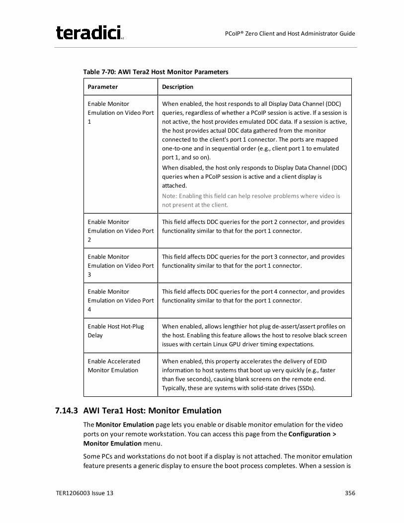
Table 7-70: AWI Tera2 Host Monitor Parameters
Parameter Description
Enable MonitorEmulation on Video Port1
When enabled, the host responds to all Display Data Channel (DDC)queries, regardless of whether a PCoIP session is active. If a session isnot active, the host provides emulated DDC data. If a session is active,the host provides actual DDC data gathered from the monitorconnected to the client's port 1 connector. The ports are mappedone-to-one and in sequential order (e.g., client port 1 to emulatedport 1, and so on).When disabled, the host only responds to Display Data Channel (DDC)queries when a PCoIP session is active and a client display isattached.Note: Enabling this field can help resolve problems where video isnot present at the client.
Enable MonitorEmulation on Video Port2
This field affects DDC queries for the port 2 connector, and providesfunctionality similar to that for the port 1 connector.
Enable MonitorEmulation on Video Port3
This field affects DDC queries for the port 3 connector, and providesfunctionality similar to that for the port 1 connector.
Enable MonitorEmulation on Video Port4
This field affects DDC queries for the port 4 connector, and providesfunctionality similar to that for the port 1 connector.
Enable Host Hot-PlugDelay
When enabled, allows lengthier hot plug de-assert/assert profiles onthe host. Enabling this feature allows the host to resolve black screenissues with certain Linux GPU driver timing expectations.
Enable AcceleratedMonitor Emulation
When enabled, this property accelerates the delivery of EDIDinformation to host systems that boot up very quickly (e.g., fasterthan five seconds), causing blank screens on the remote end.Typically, these are systems with solid-state drives (SSDs).
7.14.3 AWI Tera1 Host: Monitor EmulationTheMonitor Emulation page lets you enable or disable monitor emulation for the videoports on your remote workstation. You can access this page from the Configuration >Monitor Emulationmenu.
Some PCs and workstations do not boot if a display is not attached. Themonitor emulationfeature presents a generic display to ensure the boot process completes. When a session is
TER1206003 Issue 13 356
PCoIP® Zero Client and Host Administrator Guide
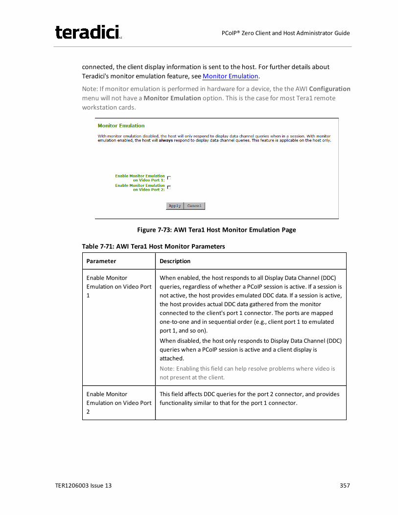
connected, the client display information is sent to the host. For further details aboutTeradici's monitor emulation feature, seeMonitor Emulation.
Note: If monitor emulation is performed in hardware for a device, the the AWI Configurationmenu will not have aMonitor Emulation option. This is the case for most Tera1 remoteworkstation cards.
Figure 7-73: AWI Tera1 Host Monitor Emulation Page
Table 7-71: AWI Tera1 Host Monitor Parameters
Parameter Description
Enable MonitorEmulation on Video Port1
When enabled, the host responds to all Display Data Channel (DDC)queries, regardless of whether a PCoIP session is active. If a session isnot active, the host provides emulated DDC data. If a session is active,the host provides actual DDC data gathered from the monitorconnected to the client's port 1 connector. The ports are mappedone-to-one and in sequential order (e.g., client port 1 to emulatedport 1, and so on).When disabled, the host only responds to Display Data Channel (DDC)queries when a PCoIP session is active and a client display isattached.Note: Enabling this field can help resolve problems where video isnot present at the client.
Enable MonitorEmulation on Video Port2
This field affects DDC queries for the port 2 connector, and providesfunctionality similar to that for the port 1 connector.
TER1206003 Issue 13 357
PCoIP® Zero Client and Host Administrator Guide
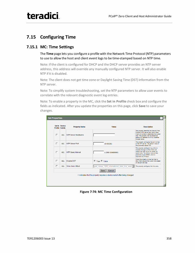
7.15 Configuring Time
7.15.1 MC: Time SettingsThe Time page lets you configure a profile with the Network Time Protocol (NTP) parametersto use to allow the host and client event logs to be time-stamped based on NTP time.
Note: If the client is configured for DHCP and the DHCP server provides an NTP serveraddress, this address will override any manually configured NTP server. It will also enableNTP if it is disabled.
Note: The client does not get time zone or Daylight Saving Time (DST) information from theNTP server.
Note: To simplify system troubleshooting, set the NTP parameters to allow user events tocorrelate with the relevant diagnostic event log entries.
Note: To enable a property in theMC, click the Set in Profile check box and configure thefields as indicated. After you update the properties on this page, click Save to save yourchanges.
Figure 7-74: MC Time Configuration
TER1206003 Issue 13 358
PCoIP® Zero Client and Host Administrator Guide
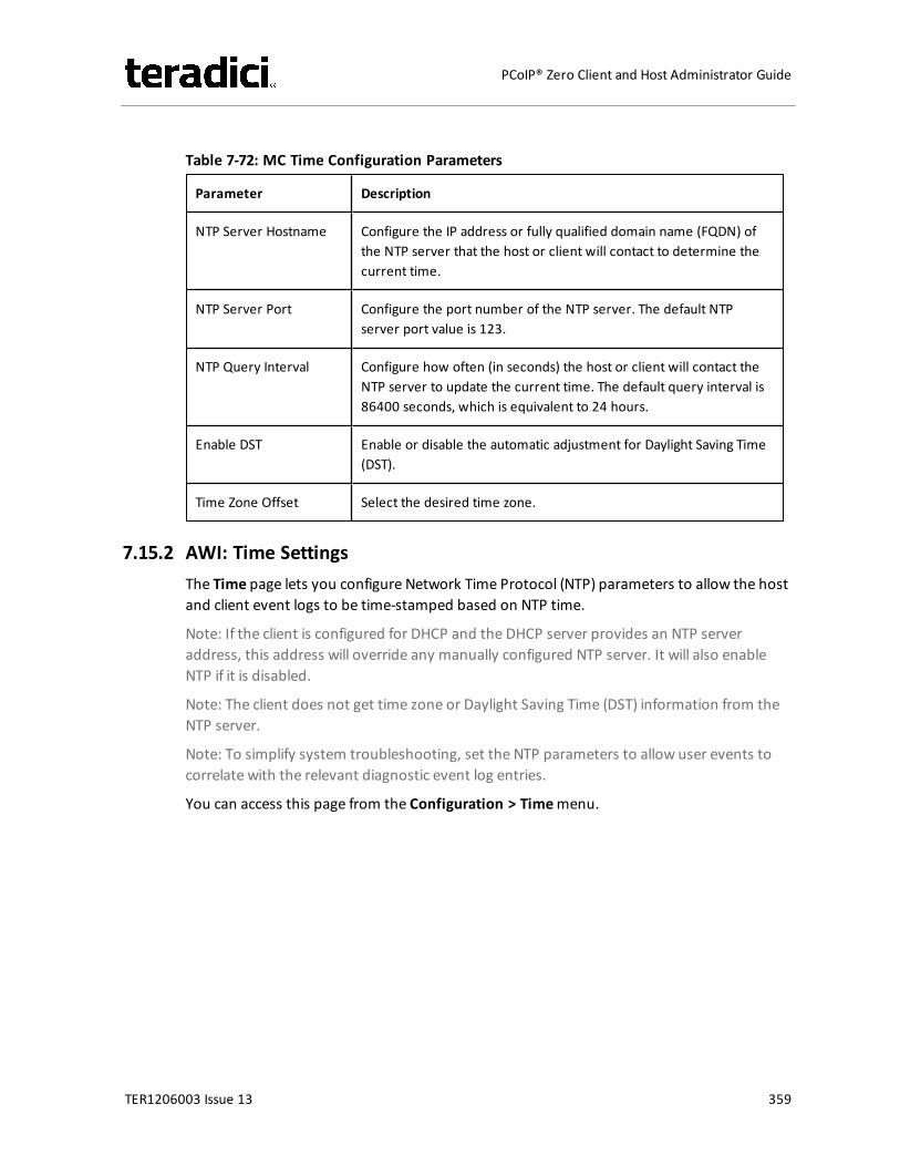
Table 7-72: MC Time Configuration Parameters
Parameter Description
NTP Server Hostname Configure the IP address or fully qualified domain name (FQDN) ofthe NTP server that the host or client will contact to determine thecurrent time.
NTP Server Port Configure the port number of the NTP server. The default NTPserver port value is 123.
NTP Query Interval Configure how often (in seconds) the host or client will contact theNTP server to update the current time. The default query interval is86400 seconds, which is equivalent to 24 hours.
Enable DST Enable or disable the automatic adjustment for Daylight Saving Time(DST).
Time Zone Offset Select the desired time zone.
7.15.2 AWI: Time SettingsThe Time page lets you configure Network Time Protocol (NTP) parameters to allow the hostand client event logs to be time-stamped based on NTP time.
Note: If the client is configured for DHCP and the DHCP server provides an NTP serveraddress, this address will override any manually configured NTP server. It will also enableNTP if it is disabled.
Note: The client does not get time zone or Daylight Saving Time (DST) information from theNTP server.
Note: To simplify system troubleshooting, set the NTP parameters to allow user events tocorrelate with the relevant diagnostic event log entries.
You can access this page from the Configuration > Timemenu.
TER1206003 Issue 13 359
PCoIP® Zero Client and Host Administrator Guide
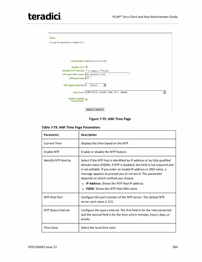
Figure 7-75: AWI Time Page
Table 7-73: AWI Time Page Parameters
Parameter Description
Current Time Displays the time based on the NTP.
Enable NTP Enable or disable the NTP feature.
Identify NTP Host by Select if the NTP host is identified by IP address or by fully qualifieddomain name (FQDN). If NTP is disabled, this field is not required andis not editable. If you enter an invalid IP address or DNS name, amessage appears to prompt you to correct it. The parameterdepends on which method you choose.l IP Address: Shows the NTP Host IP addressl FQDN: Shows the NTP Host DNS name
NTP Host Port Configure the port number of the NTP server. The default NTPserver port value is 123.
NTP Query Interval Configure the query interval. The first field is for the interval periodand the second field is for the time unit in minutes, hours, days, orweeks.
Time Zone Select the local time zone.
TER1206003 Issue 13 360
PCoIP® Zero Client and Host Administrator Guide
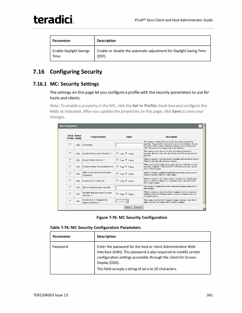
Parameter Description
Enable Daylight SavingsTime
Enable or disable the automatic adjustment for Daylight Saving Time(DST).
7.16 Configuring Security
7.16.1 MC: Security SettingsThe settings on this page let you configure a profile with the security parameters to use forhosts and clients.
Note: To enable a property in theMC, click the Set in Profile check box and configure thefields as indicated. After you update the properties on this page, click Save to save yourchanges.
Figure 7-76: MC Security Configuration
Table 7-74: MC Security Configuration Parameters
Parameter Description
Password Enter the password for the host or client Administrative WebInterface (AWI). This password is also required to modify certainconfiguration settings accessible through the client On ScreenDisplay (OSD).This field accepts a string of zero to 20 characters.
TER1206003 Issue 13 361
PCoIP® Zero Client and Host Administrator Guide
Parameter Description
Enable PasswordProtection
When enabled, the host or client AWI password is required.When disabled, the AWI and OSD are not password protected.
Note: This property requires a device restart after being changed.
Enable Web Interface When enabled, the host or client can be accessed and managedusing the AWI is enabled. When disabled, the device cannot beaccessed or managed using the AWI.Note: This property requires a device restart after being changed.
Enable HotkeyParameter Reset
When enabled, the client can be reset to its factory defaults usingthe keyboard combination Ctrl+Alt+Shift+Space when the client isnot in a PCoIP session.
Hide Parameter ResetHotkey Sequence
When enabled, the reset hotkey sequence is not shown on the clientOSD.
Enable 802.1X Security When enabled, the device will perform 802.1x authentication if it isconnected to a network where access is controlled using 802.1xauthentication.
802.1X AuthenticationIdentity
Configure the username to present for 802.1x authentication.
Disable ManagementConsole Interface
When enabled, the management console interface is disabled, andthe device cannot be accessed or managed by the MC (or any otherPCoIP device management tool).Note: This property requires a device restart after being changed.
Enable 802.1X Supportfor Legacy Switches
When enabled, allows greater 802.1x compatability for olderswitches on the network.Note: This property requires a device restart after being changed.
7.16.2 AWI: Help for Security SettingsThe following 802.1x security settings for the AWI are located on the Network page (accessedfrom the Configuration > Networkmenu):
l Enable 802.1x Securityl Authenticationl Identityl Client Certificatel Enable 802.1x Legacy Support
TER1206003 Issue 13 362
PCoIP® Zero Client and Host Administrator Guide
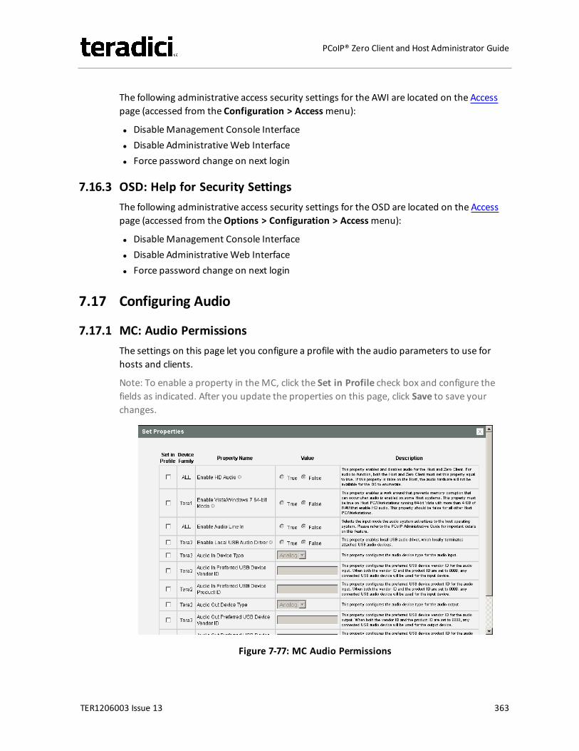
The following administrative access security settings for the AWI are located on the Accesspage (accessed from the Configuration > Accessmenu):
l DisableManagement Console Interfacel Disable AdministrativeWeb Interfacel Force password change on next login
7.16.3 OSD: Help for Security SettingsThe following administrative access security settings for the OSD are located on the Accesspage (accessed from theOptions > Configuration > Accessmenu):
l DisableManagement Console Interfacel Disable AdministrativeWeb Interfacel Force password change on next login
7.17 Configuring Audio
7.17.1 MC: Audio PermissionsThe settings on this page let you configure a profile with the audio parameters to use forhosts and clients.
Note: To enable a property in theMC, click the Set in Profile check box and configure thefields as indicated. After you update the properties on this page, click Save to save yourchanges.
Figure 7-77: MC Audio Permissions
TER1206003 Issue 13 363
PCoIP® Zero Client and Host Administrator Guide
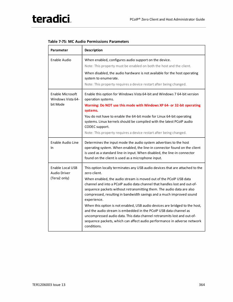
Table 7-75: MC Audio Permissions Parameters
Parameter Description
Enable Audio When enabled, configures audio support on the device.Note: This property must be enabled on both the host and the client.
When disabled, the audio hardware is not available for the host operatingsystem to enumerate.Note: This property requires a device restart after being changed.
Enable MicrosoftWindows Vista 64-bit Mode
Enable this option for Windows Vista 64-bit and Windows 7 64-bit versionoperation systems.Warning: Do NOT use this mode with Windows XP 64- or 32-bit operatingsystems.You do not have to enable the 64-bit mode for Linux 64-bit operatingsystems. Linux kernels should be compiled with the latest PCoIP audioCODEC support.Note: This property requires a device restart after being changed.
Enable Audio LineIn
Determines the input mode the audio system advertises to the hostoperating system. When enabled, the line-in connector found on the clientis used as a standard line-in input. When disabled, the line-in connectorfound on the client is used as a microphone input.
Enable Local USBAudio Driver(Tera2 only)
This option locally terminates any USB audio devices that are attached to thezero client.When enabled, the audio stream is moved out of the PCoIP USB datachannel and into a PCoIP audio data channel that handles lost and out-of-sequence packets without retransmitting them. The audio data are alsocompressed, resulting in bandwidth savings and a much improved soundexperience.When this option is not enabled, USB audio devices are bridged to the host,and the audio stream is embedded in the PCoIP USB data channel asuncompressed audio data. This data channel retransmits lost and out-of-sequence packets, which can affect audio performance in adverse networkconditions.
TER1206003 Issue 13 364
PCoIP® Zero Client and Host Administrator Guide
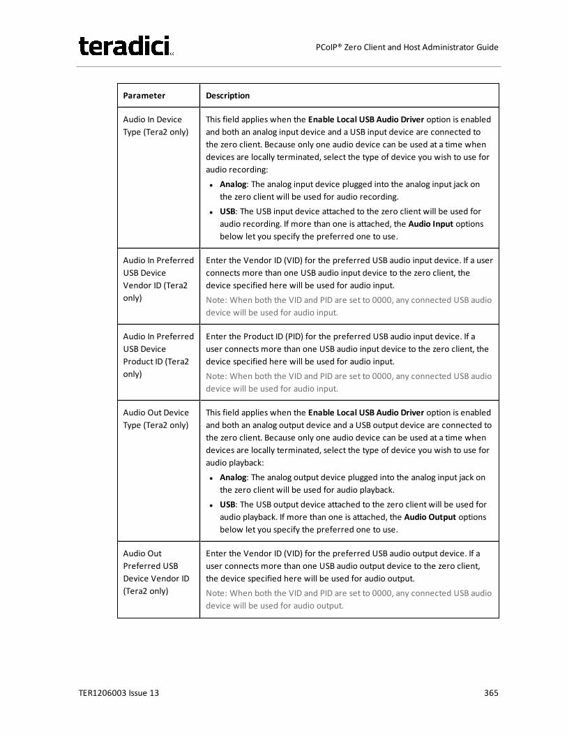
Parameter Description
Audio In DeviceType (Tera2 only)
This field applies when the Enable Local USB Audio Driver option is enabledand both an analog input device and a USB input device are connected tothe zero client. Because only one audio device can be used at a time whendevices are locally terminated, select the type of device you wish to use foraudio recording:l Analog: The analog input device plugged into the analog input jack on
the zero client will be used for audio recording.l USB: The USB input device attached to the zero client will be used for
audio recording. If more than one is attached, the Audio Input optionsbelow let you specify the preferred one to use.
Audio In PreferredUSB DeviceVendor ID (Tera2only)
Enter the Vendor ID (VID) for the preferred USB audio input device. If a userconnects more than one USB audio input device to the zero client, thedevice specified here will be used for audio input.Note: When both the VID and PID are set to 0000, any connected USB audiodevice will be used for audio input.
Audio In PreferredUSB DeviceProduct ID (Tera2only)
Enter the Product ID (PID) for the preferred USB audio input device. If auser connects more than one USB audio input device to the zero client, thedevice specified here will be used for audio input.Note: When both the VID and PID are set to 0000, any connected USB audiodevice will be used for audio input.
Audio Out DeviceType (Tera2 only)
This field applies when the Enable Local USB Audio Driver option is enabledand both an analog output device and a USB output device are connected tothe zero client. Because only one audio device can be used at a time whendevices are locally terminated, select the type of device you wish to use foraudio playback:l Analog: The analog output device plugged into the analog input jack on
the zero client will be used for audio playback.l USB: The USB output device attached to the zero client will be used for
audio playback. If more than one is attached, the Audio Output optionsbelow let you specify the preferred one to use.
Audio OutPreferred USBDevice Vendor ID(Tera2 only)
Enter the Vendor ID (VID) for the preferred USB audio output device. If auser connects more than one USB audio output device to the zero client,the device specified here will be used for audio output.Note: When both the VID and PID are set to 0000, any connected USB audiodevice will be used for audio output.
TER1206003 Issue 13 365
PCoIP® Zero Client and Host Administrator Guide
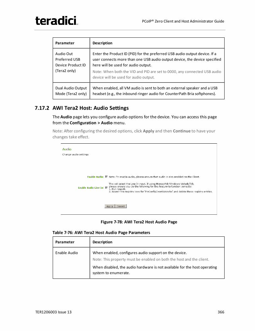
Parameter Description
Audio OutPreferred USBDevice Product ID(Tera2 only)
Enter the Product ID (PID) for the preferred USB audio output device. If auser connects more than one USB audio output device, the device specifiedhere will be used for audio output.Note: When both the VID and PID are set to 0000, any connected USB audiodevice will be used for audio output.
Dual Audio OutputMode (Tera2 only)
When enabled, all VM audio is sent to both an external speaker and a USBheadset (e.g., the inbound ringer audio for CounterPath Bria softphones).
7.17.2 AWI Tera2 Host: Audio SettingsThe Audio page lets you configure audio options for the device. You can access this pagefrom the Configuration > Audiomenu.
Note: After configuring the desired options, click Apply and then Continue to have yourchanges take effect.
Figure 7-78: AWI Tera2 Host Audio Page
Table 7-76: AWI Tera2 Host Audio Page Parameters
Parameter Description
Enable Audio When enabled, configures audio support on the device.Note: This property must be enabled on both the host and the client.
When disabled, the audio hardware is not available for the host operatingsystem to enumerate.
TER1206003 Issue 13 366
PCoIP® Zero Client and Host Administrator Guide
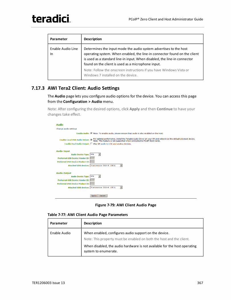
Parameter Description
Enable Audio LineIn
Determines the input mode the audio system advertises to the hostoperating system. When enabled, the line-in connector found on the clientis used as a standard line-in input. When disabled, the line-in connectorfound on the client is used as a microphone input.Note: Follow the onscreen instructions if you have Windows Vista orWindows 7 installed on the device.
7.17.3 AWI Tera2 Client: Audio SettingsThe Audio page lets you configure audio options for the device. You can access this pagefrom the Configuration > Audiomenu.
Note: After configuring the desired options, click Apply and then Continue to have yourchanges take effect.
Figure 7-79: AWI Client Audio Page
Table 7-77: AWI Client Audio Page Parameters
Parameter Description
Enable Audio When enabled, configures audio support on the device.Note: This property must be enabled on both the host and the client.
When disabled, the audio hardware is not available for the host operatingsystem to enumerate.
TER1206003 Issue 13 367
PCoIP® Zero Client and Host Administrator Guide
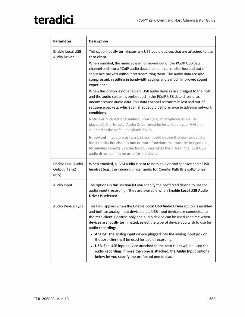
Parameter Description
Enable Local USBAudio Driver
This option locally terminates any USB audio devices that are attached to thezero client.When enabled, the audio stream is moved out of the PCoIP USB datachannel and into a PCoIP audio data channel that handles lost and out-of-sequence packets without retransmitting them. The audio data are alsocompressed, resulting in bandwidth savings and a much improved soundexperience.When this option is not enabled, USB audio devices are bridged to the host,and the audio stream is embedded in the PCoIP USB data channel asuncompressed audio data. This data channel retransmits lost and out-of-sequence packets, which can affect audio performance in adverse networkconditions.Note: For bi-directional audio support (e.g., microphone as well asplayback), the Teradici Audio Driver must be installed on your VM andselected as the default playback device.
Important! If you are using a USB composite device that contains audiofunctionality but also has one or more functions that must be bridged (i.e.,terminated remotely so the host OS can install the driver), the local USBaudio driver cannot be used for the device.
Enable Dual AudioOutput (Tera2only)
When enabled, all VM audio is sent to both an external speaker and a USBheadset (e.g., the inbound ringer audio for CounterPath Bria softphones).
Audio Input The options in this section let you specify the preferred device to use foraudio input (recording). They are available when Enable Local USB AudioDriver is selected.
Audio Device Type This field applies when the Enable Local USB Audio Driver option is enabledand both an analog input device and a USB input device are connected tothe zero client. Because only one audio device can be used at a time whendevices are locally terminated, select the type of device you wish to use foraudio recording:l Analog: The analog input device plugged into the analog input jack on
the zero client will be used for audio recording.l USB: The USB input device attached to the zero client will be used for
audio recording. If more than one is attached, the Audio Input optionsbelow let you specify the preferred one to use.
TER1206003 Issue 13 368
PCoIP® Zero Client and Host Administrator Guide
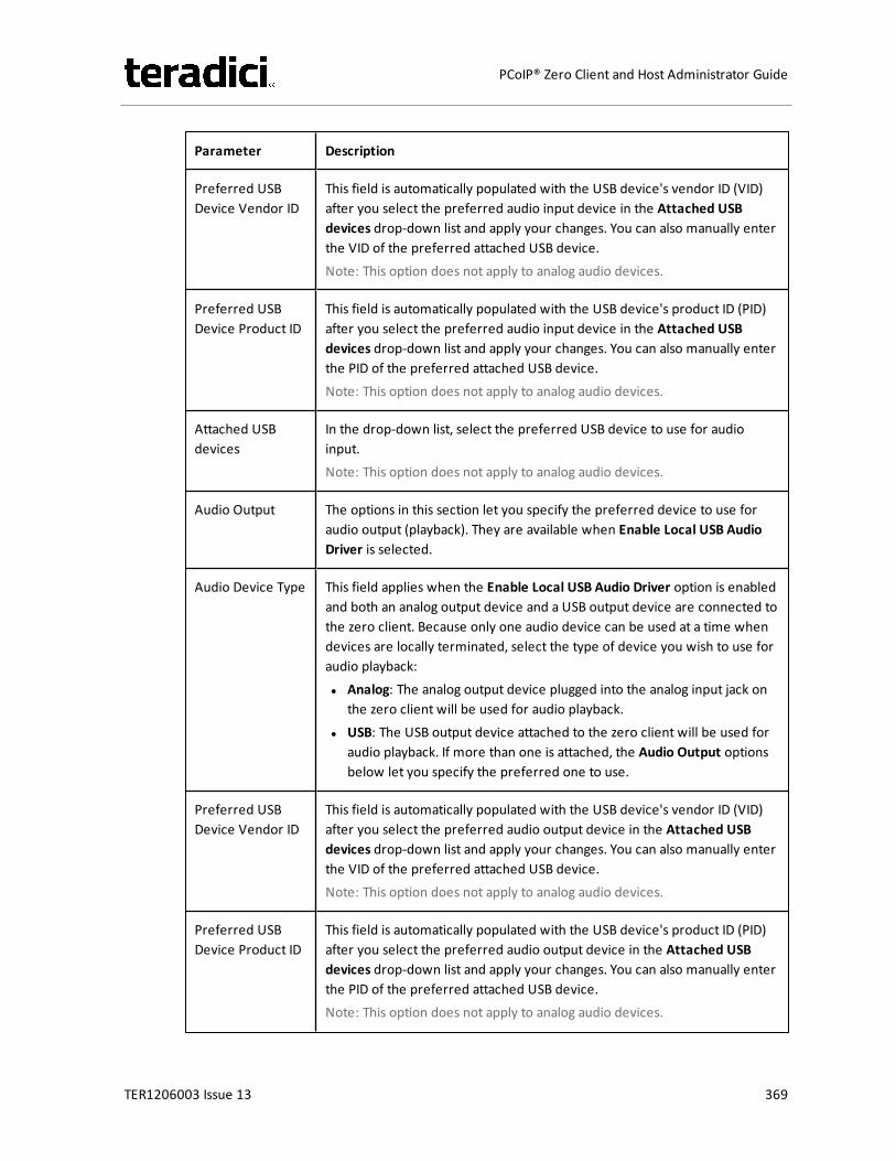
Parameter Description
Preferred USBDevice Vendor ID
This field is automatically populated with the USB device's vendor ID (VID)after you select the preferred audio input device in the Attached USBdevices drop-down list and apply your changes. You can also manually enterthe VID of the preferred attached USB device.Note: This option does not apply to analog audio devices.
Preferred USBDevice Product ID
This field is automatically populated with the USB device's product ID (PID)after you select the preferred audio input device in the Attached USBdevices drop-down list and apply your changes. You can also manually enterthe PID of the preferred attached USB device.Note: This option does not apply to analog audio devices.
Attached USBdevices
In the drop-down list, select the preferred USB device to use for audioinput.Note: This option does not apply to analog audio devices.
Audio Output The options in this section let you specify the preferred device to use foraudio output (playback). They are available when Enable Local USB AudioDriver is selected.
Audio Device Type This field applies when the Enable Local USB Audio Driver option is enabledand both an analog output device and a USB output device are connected tothe zero client. Because only one audio device can be used at a time whendevices are locally terminated, select the type of device you wish to use foraudio playback:l Analog: The analog output device plugged into the analog input jack on
the zero client will be used for audio playback.l USB: The USB output device attached to the zero client will be used for
audio playback. If more than one is attached, the Audio Output optionsbelow let you specify the preferred one to use.
Preferred USBDevice Vendor ID
This field is automatically populated with the USB device's vendor ID (VID)after you select the preferred audio output device in the Attached USBdevices drop-down list and apply your changes. You can also manually enterthe VID of the preferred attached USB device.Note: This option does not apply to analog audio devices.
Preferred USBDevice Product ID
This field is automatically populated with the USB device's product ID (PID)after you select the preferred audio output device in the Attached USBdevices drop-down list and apply your changes. You can also manually enterthe PID of the preferred attached USB device.Note: This option does not apply to analog audio devices.
TER1206003 Issue 13 369
PCoIP® Zero Client and Host Administrator Guide
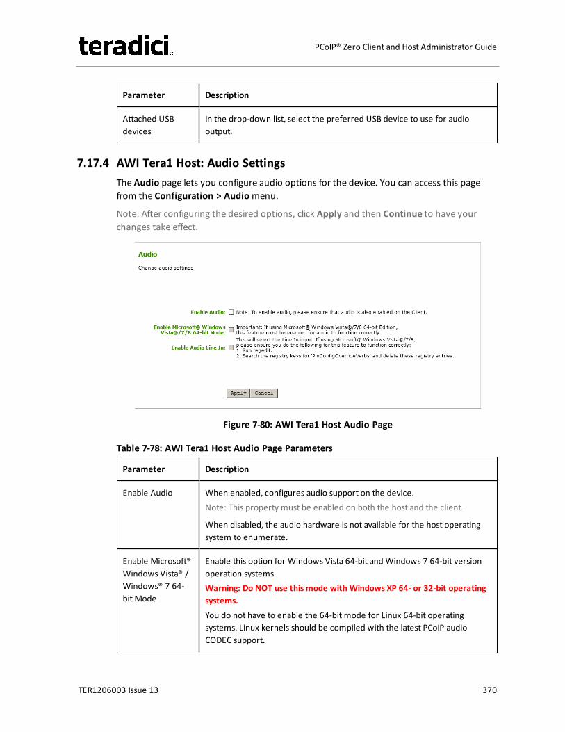
Parameter Description
Attached USBdevices
In the drop-down list, select the preferred USB device to use for audiooutput.
7.17.4 AWI Tera1 Host: Audio SettingsThe Audio page lets you configure audio options for the device. You can access this pagefrom the Configuration > Audiomenu.
Note: After configuring the desired options, click Apply and then Continue to have yourchanges take effect.
Figure 7-80: AWI Tera1 Host Audio Page
Table 7-78: AWI Tera1 Host Audio Page Parameters
Parameter Description
Enable Audio When enabled, configures audio support on the device.Note: This property must be enabled on both the host and the client.
When disabled, the audio hardware is not available for the host operatingsystem to enumerate.
Enable Microsoft®Windows Vista® /Windows® 7 64-bit Mode
Enable this option for Windows Vista 64-bit and Windows 7 64-bit versionoperation systems.Warning: Do NOT use this mode with Windows XP 64- or 32-bit operatingsystems.You do not have to enable the 64-bit mode for Linux 64-bit operatingsystems. Linux kernels should be compiled with the latest PCoIP audioCODEC support.
TER1206003 Issue 13 370
PCoIP® Zero Client and Host Administrator Guide
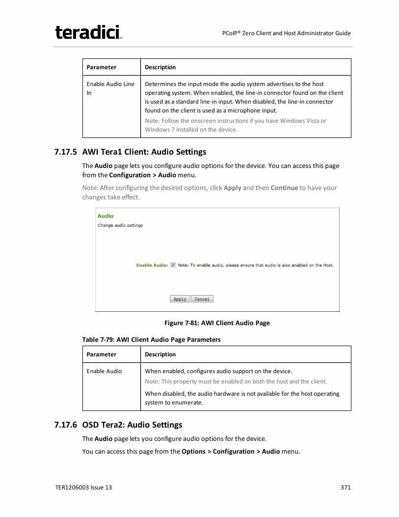
Parameter Description
Enable Audio LineIn
Determines the input mode the audio system advertises to the hostoperating system. When enabled, the line-in connector found on the clientis used as a standard line-in input. When disabled, the line-in connectorfound on the client is used as a microphone input.Note: Follow the onscreen instructions if you have Windows Vista orWindows 7 installed on the device.
7.17.5 AWI Tera1 Client: Audio SettingsThe Audio page lets you configure audio options for the device. You can access this pagefrom the Configuration > Audiomenu.
Note: After configuring the desired options, click Apply and then Continue to have yourchanges take effect.
Figure 7-81: AWI Client Audio Page
Table 7-79: AWI Client Audio Page Parameters
Parameter Description
Enable Audio When enabled, configures audio support on the device.Note: This property must be enabled on both the host and the client.
When disabled, the audio hardware is not available for the host operatingsystem to enumerate.
7.17.6 OSD Tera2: Audio SettingsThe Audio page lets you configure audio options for the device.
You can access this page from theOptions > Configuration > Audiomenu.
TER1206003 Issue 13 371
PCoIP® Zero Client and Host Administrator Guide
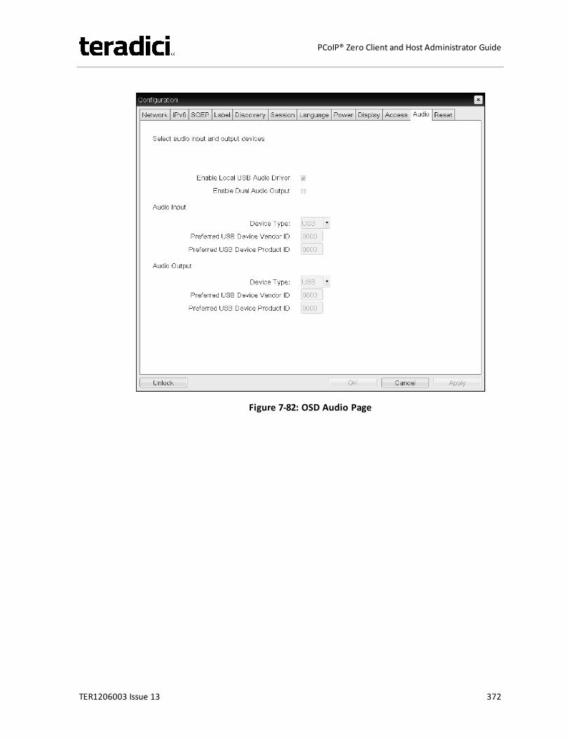
Figure 7-82: OSD Audio Page
TER1206003 Issue 13 372
PCoIP® Zero Client and Host Administrator Guide

Table 7-80: OSD Audio Page Parameters
Parameter Description
Enable Local USBAudio Driver
This option locally terminates any USB audio devices that are attached to thezero client.When enabled, the audio stream is moved out of the PCoIP USB datachannel and into a PCoIP audio data channel that handles lost and out-of-sequence packets without retransmitting them. The audio data are alsocompressed, resulting in bandwidth savings and a much improved soundexperience.When this option is not enabled, USB audio devices are bridged to the host,and the audio stream is embedded in the PCoIP USB data channel asuncompressed audio data. This data channel retransmits lost and out-of-sequence packets, which can affect audio performance in adverse networkconditions.Note: For bi-directional audio support (e.g., microphone as well asplayback), the Teradici Audio Driver must be installed on your VM andselected as the default playback device.
Important! If you are using a USB composite device that contains audiofunctionality but also has one or more functions that must be bridged (i.e.,terminated remotely so the host OS can install the driver), the local USBaudio driver cannot be used for the device.
Enable Dual AudioOutput (Tera2only)
When enabled, all VM audio is sent to both an external speaker and a USBheadset (e.g., the inbound ringer audio for CounterPath Bria softphones).
Audio Input The options in this section let you specify the preferred device to use foraudio input (recording). They are available when Enable Local USB AudioDriver is selected.
Device Type This field applies when the Enable Local USB Audio Driver option is enabledand both an analog input device and a USB input device are connected tothe zero client. Because only one audio device can be used at a time whendevices are locally terminated, select the type of device you wish to use foraudio recording:l Analog: The analog input device plugged into the analog input jack on
the zero client will be used for audio recording.l USB: The USB input device attached to the zero client will be used for
audio recording. If more than one is attached, the Audio Input optionsbelow let you specify the preferred one to use.
TER1206003 Issue 13 373
PCoIP® Zero Client and Host Administrator Guide
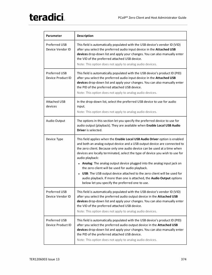
Parameter Description
Preferred USBDevice Vendor ID
This field is automatically populated with the USB device's vendor ID (VID)after you select the preferred audio input device in the Attached USBdevices drop-down list and apply your changes. You can also manually enterthe VID of the preferred attached USB device.Note: This option does not apply to analog audio devices.
Preferred USBDevice Product ID
This field is automatically populated with the USB device's product ID (PID)after you select the preferred audio input device in the Attached USBdevices drop-down list and apply your changes. You can also manually enterthe PID of the preferred attached USB device.Note: This option does not apply to analog audio devices.
Attached USBdevices
In the drop-down list, select the preferred USB device to use for audioinput.Note: This option does not apply to analog audio devices.
Audio Output The options in this section let you specify the preferred device to use foraudio output (playback). They are available when Enable Local USB AudioDriver is selected.
Device Type This field applies when the Enable Local USB Audio Driver option is enabledand both an analog output device and a USB output device are connected tothe zero client. Because only one audio device can be used at a time whendevices are locally terminated, select the type of device you wish to use foraudio playback:l Analog: The analog output device plugged into the analog input jack on
the zero client will be used for audio playback.l USB: The USB output device attached to the zero client will be used for
audio playback. If more than one is attached, the Audio Output optionsbelow let you specify the preferred one to use.
Preferred USBDevice Vendor ID
This field is automatically populated with the USB device's vendor ID (VID)after you select the preferred audio output device in the Attached USBdevices drop-down list and apply your changes. You can also manually enterthe VID of the preferred attached USB device.Note: This option does not apply to analog audio devices.
Preferred USBDevice Product ID
This field is automatically populated with the USB device's product ID (PID)after you select the preferred audio output device in the Attached USBdevices drop-down list and apply your changes. You can also manually enterthe PID of the preferred attached USB device.Note: This option does not apply to analog audio devices.
TER1206003 Issue 13 374
PCoIP® Zero Client and Host Administrator Guide
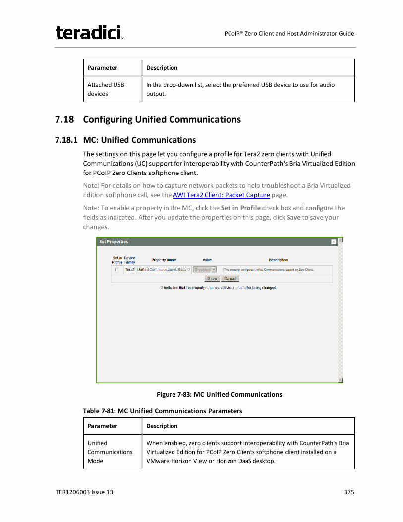
Parameter Description
Attached USBdevices
In the drop-down list, select the preferred USB device to use for audiooutput.
7.18 Configuring Unified Communications
7.18.1 MC: Unified CommunicationsThe settings on this page let you configure a profile for Tera2 zero clients with UnifiedCommunications (UC) support for interoperability with CounterPath's Bria Virtualized Editionfor PCoIP Zero Clients softphone client.
Note: For details on how to capture network packets to help troubleshoot a Bria VirtualizedEdition softphone call, see the AWI Tera2 Client: Packet Capture page.
Note: To enable a property in theMC, click the Set in Profile check box and configure thefields as indicated. After you update the properties on this page, click Save to save yourchanges.
Figure 7-83: MC Unified Communications
Table 7-81: MC Unified Communications Parameters
Parameter Description
UnifiedCommunicationsMode
When enabled, zero clients support interoperability with CounterPath's BriaVirtualized Edition for PCoIP Zero Clients softphone client installed on aVMware Horizon View or Horizon DaaS desktop.
TER1206003 Issue 13 375
PCoIP® Zero Client and Host Administrator Guide
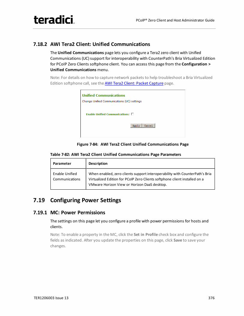
7.18.2 AWI Tera2 Client: Unified CommunicationsTheUnified Communications page lets you configure a Tera2 zero client with UnifiedCommunications (UC) support for interoperability with CounterPath's Bria Virtualized Editionfor PCoIP Zero Clients softphone client. You can access this page from the Configuration >Unified Communicationsmenu.
Note: For details on how to capture network packets to help troubleshoot a Bria VirtualizedEdition softphone call, see the AWI Tera2 Client: Packet Capture page.
Figure 7-84: AWI Tera2 Client Unified Communications Page
Table 7-82: AWI Tera2 Client Unified Communications Page Parameters
Parameter Description
Enable UnifiedCommunications
When enabled, zero clients support interoperability with CounterPath's BriaVirtualized Edition for PCoIP Zero Clients softphone client installed on aVMware Horizon View or Horizon DaaS desktop.
7.19 Configuring Power Settings
7.19.1 MC: Power PermissionsThe settings on this page let you configure a profile with power permissions for hosts andclients.
Note: To enable a property in theMC, click the Set in Profile check box and configure thefields as indicated. After you update the properties on this page, click Save to save yourchanges.
TER1206003 Issue 13 376
PCoIP® Zero Client and Host Administrator Guide
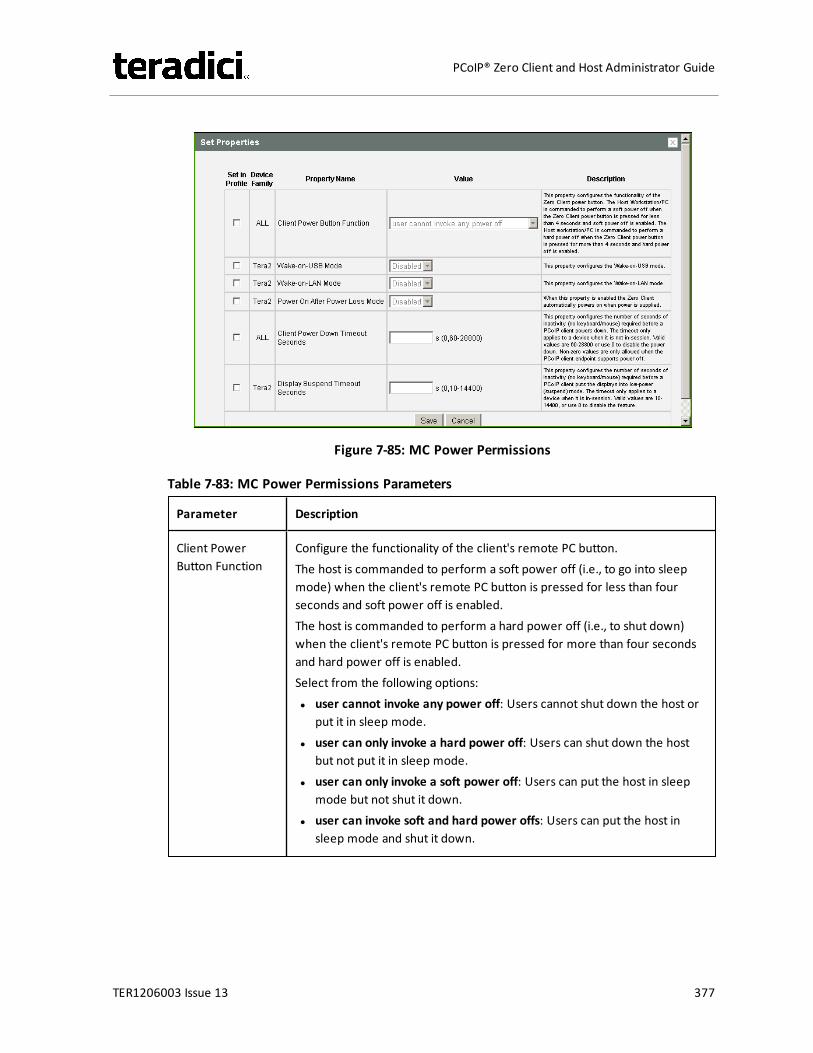
Figure 7-85: MC Power Permissions
Table 7-83: MC Power Permissions Parameters
Parameter Description
Client PowerButton Function
Configure the functionality of the client's remote PC button.The host is commanded to perform a soft power off (i.e., to go into sleepmode) when the client's remote PC button is pressed for less than fourseconds and soft power off is enabled.The host is commanded to perform a hard power off (i.e., to shut down)when the client's remote PC button is pressed for more than four secondsand hard power off is enabled.Select from the following options:l user cannot invoke any power off: Users cannot shut down the host or
put it in sleep mode.l user can only invoke a hard power off: Users can shut down the host
but not put it in sleep mode.l user can only invoke a soft power off: Users can put the host in sleep
mode but not shut it down.l user can invoke soft and hard power offs: Users can put the host in
sleep mode and shut it down.
TER1206003 Issue 13 377
PCoIP® Zero Client and Host Administrator Guide

Parameter Description
Wake-on-USBMode
When enabled, configures the client to power up when the user presses akey on the keyboard. Wake-on-USB applies when the client is eitherpowered off automatically or as a result of the user holding down thepower button.Note: Clicking or moving the mouse will not power up the client when thisfeature is enabled.
Wake-on-LANMode
When enabled, configures Wake-on-LAN mode in hosts and clients thatsupport this feature. Wake-on-LAN mode allows a device to wake up fromsleep mode or a low power state when it receives Wake-on-LAN magicpackets.
Power On AfterPower Loss Mode
When enabled, the client automatically powers back on when power issupplied.
Client PowerDown TimeoutSeconds
Configure the number of seconds to wait after a period of inactivity (i.e., nokeyboard or mouse action) before the client powers down. Valid values are60 to 28800 seconds, or use 0 to disable the power down.Note: Non-zero values are only allowed when the PCoIP client supportspowering off.
Note: This timeout only applies when the device is not in session.
Display SuspendTimeout Seconds
Configure the number of seconds to wait after a period of inactivity (i.e., nokeyboard or mouse action) before the client puts its attached displays intolow power mode. Valid values are 10 to 14400 seconds, or use 0 to disablethe feature.Note: This timeout only applies when the device is in session.
Note: When connected to a workstation, this feature requires Local Mouseand Keyboard to be enabled.
7.19.2 AWI Tera2 Host: Power SettingsThe Power page lets you configure power settings for the host. You can access this pagefrom the Configuration > Powermenu.
TER1206003 Issue 13 378
PCoIP® Zero Client and Host Administrator Guide
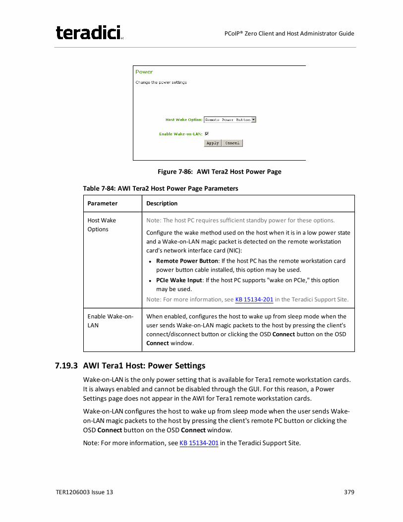
Figure 7-86: AWI Tera2 Host Power Page
Table 7-84: AWI Tera2 Host Power Page Parameters
Parameter Description
HostWakeOptions
Note: The host PC requires sufficient standby power for these options.
Configure the wake method used on the host when it is in a low power stateand aWake-on-LAN magic packet is detected on the remote workstationcard's network interface card (NIC):l Remote Power Button: If the host PC has the remote workstation card
power button cable installed, this option may be used.l PCIe Wake Input: If the host PC supports "wake on PCIe," this option
may be used.Note: For more information, see KB 15134-201 in the Teradici Support Site.
Enable Wake-on-LAN
When enabled, configures the host to wake up from sleep mode when theuser sends Wake-on-LAN magic packets to the host by pressing the client'sconnect/disconnect button or clicking the OSD Connect button on the OSDConnect window.
7.19.3 AWI Tera1 Host: Power SettingsWake-on-LAN is the only power setting that is available for Tera1 remote workstation cards.It is always enabled and cannot be disabled through the GUI. For this reason, a PowerSettings page does not appear in the AWI for Tera1 remote workstation cards.
Wake-on-LAN configures the host to wake up from sleep modewhen the user sends Wake-on-LANmagic packets to the host by pressing the client's remote PC button or clicking theOSD Connect button on the OSD Connectwindow.
Note: For more information, see KB 15134-201 in the Teradici Support Site.
TER1206003 Issue 13 379
PCoIP® Zero Client and Host Administrator Guide
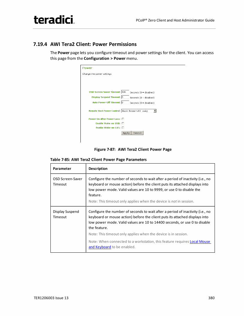
7.19.4 AWI Tera2 Client: Power PermissionsThe Power page lets you configure timeout and power settings for the client. You can accessthis page from the Configuration > Powermenu.
Figure 7-87: AWI Tera2 Client Power Page
Table 7-85: AWI Tera2 Client Power Page Parameters
Parameter Description
OSD Screen-SaverTimeout
Configure the number of seconds to wait after a period of inactivity (i.e., nokeyboard or mouse action) before the client puts its attached displays intolow power mode. Valid values are 10 to 9999, or use 0 to disable thefeature.Note: This timeout only applies when the device is not in session.
Display SuspendTimeout
Configure the number of seconds to wait after a period of inactivity (i.e., nokeyboard or mouse action) before the client puts its attached displays intolow power mode. Valid values are 10 to 14400 seconds, or use 0 to disablethe feature.Note: This timeout only applies when the device is in session.
Note: When connected to a workstation, this feature requires Local Mouseand Keyboard to be enabled.
TER1206003 Issue 13 380
PCoIP® Zero Client and Host Administrator Guide
Parameter Description
Auto Power-OffTimeout
Configure the number of seconds to wait after a period of inactivity (i.e., nokeyboard or mouse action) before the client powers down. Valid values are60 to 28800 seconds, or use 0 to disable the power down.Note: Non-zero values are only allowed when the PCoIP client supportspowering off.
Note: This timeout only applies when the device is not in session.
Remote HostPower Control
Configure the client's remote power setting.Select from the following options:l Power-off not permitted: Users cannot remotely shut down the host PC
from the zero client. When this option is selected, the Zero ClientControl Panel on the OSD does not appear when the zero client'sconnect/disconnect button is pressed.
l Hard Power-off only: Users are able to remotely shut down the hostfrom the zero client. When this option is selected, the Zero ClientControl Panel on the OSD appears when the zero client'sconnect/disconnect button is pressed.
Power On AfterPower Loss
When enabled, the client automatically powers back on when power issupplied.
Enable Wake-on-USB
When enabled, configures the client to power up when the user presses akey on the keyboard. Wake-on-USB applies when the client is eitherpowered off automatically or as a result of the user holding down thepower button.Note: Clicking or moving the mouse will not power up the client when thisfeature is enabled.
Enable Wake-on-LAN
When enabled, configures the client to wake up from a low power statewhen it receives Wake-on-LAN magic packets.
7.19.5 AWI Tera1 Client: Power SettingsThe Power page lets you configure timeout and power settings for the client. You can accessthis page from the Configuration > Powermenu.
TER1206003 Issue 13 381
PCoIP® Zero Client and Host Administrator Guide
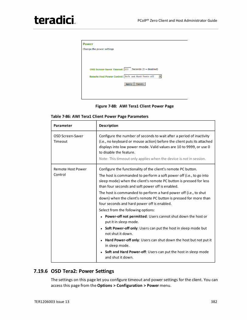
Figure 7-88: AWI Tera1 Client Power Page
Table 7-86: AWI Tera1 Client Power Page Parameters
Parameter Description
OSD Screen-SaverTimeout
Configure the number of seconds to wait after a period of inactivity(i.e., no keyboard or mouse action) before the client puts its attacheddisplays into low power mode. Valid values are 10 to 9999, or use 0to disable the feature.Note: This timeout only applies when the device is not in session.
Remote Host PowerControl
Configure the functionality of the client's remote PC button.The host is commanded to perform a soft power off (i.e., to go intosleep mode) when the client's remote PC button is pressed for lessthan four seconds and soft power off is enabled.The host is commanded to perform a hard power off (i.e., to shutdown) when the client's remote PC button is pressed for more thanfour seconds and hard power off is enabled.Select from the following options:l Power-off not permitted: Users cannot shut down the host or
put it in sleep mode.l Soft Power-off only: Users can put the host in sleep mode but
not shut it down.l Hard Power-off only: Users can shut down the host but not put it
in sleep mode.l Soft and Hard Power-off: Users can put the host in sleep mode
and shut it down.
7.19.6 OSD Tera2: Power SettingsThe settings on this page let you configure timeout and power settings for the client. You canaccess this page from theOptions > Configuration > Powermenu.
TER1206003 Issue 13 382
PCoIP® Zero Client and Host Administrator Guide
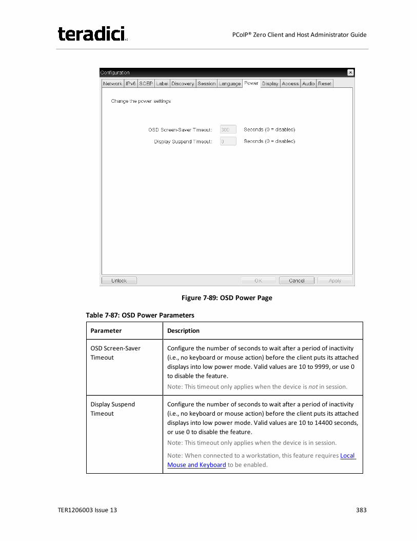
Figure 7-89: OSD Power Page
Table 7-87: OSD Power Parameters
Parameter Description
OSD Screen-SaverTimeout
Configure the number of seconds to wait after a period of inactivity(i.e., no keyboard or mouse action) before the client puts its attacheddisplays into low power mode. Valid values are 10 to 9999, or use 0to disable the feature.Note: This timeout only applies when the device is not in session.
Display SuspendTimeout
Configure the number of seconds to wait after a period of inactivity(i.e., no keyboard or mouse action) before the client puts its attacheddisplays into low power mode. Valid values are 10 to 14400 seconds,or use 0 to disable the feature.Note: This timeout only applies when the device is in session.
Note: When connected to a workstation, this feature requires LocalMouse and Keyboard to be enabled.
TER1206003 Issue 13 383
PCoIP® Zero Client and Host Administrator Guide
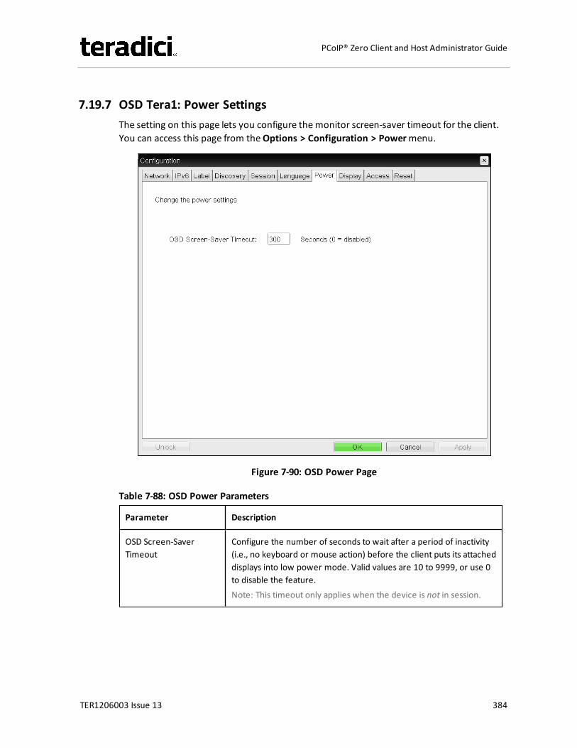
7.19.7 OSD Tera1: Power SettingsThe setting on this page lets you configure themonitor screen-saver timeout for the client.You can access this page from theOptions > Configuration > Powermenu.
Figure 7-90: OSD Power Page
Table 7-88: OSD Power Parameters
Parameter Description
OSD Screen-SaverTimeout
Configure the number of seconds to wait after a period of inactivity(i.e., no keyboard or mouse action) before the client puts its attacheddisplays into low power mode. Valid values are 10 to 9999, or use 0to disable the feature.Note: This timeout only applies when the device is not in session.
TER1206003 Issue 13 384
PCoIP® Zero Client and Host Administrator Guide
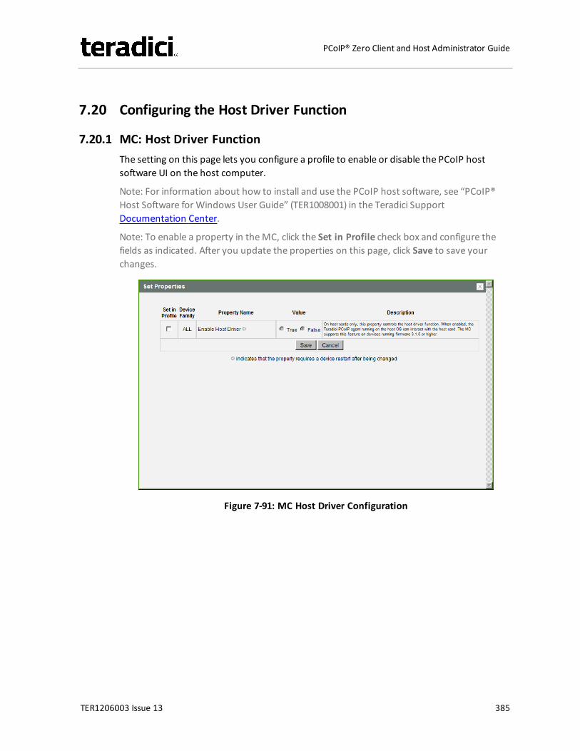
7.20 Configuring the Host Driver Function
7.20.1 MC: Host Driver FunctionThe setting on this page lets you configure a profile to enable or disable the PCoIP hostsoftware UI on the host computer.
Note: For information about how to install and use the PCoIP host software, see “PCoIP®Host Software for Windows User Guide” (TER1008001) in the Teradici SupportDocumentation Center.
Note: To enable a property in theMC, click the Set in Profile check box and configure thefields as indicated. After you update the properties on this page, click Save to save yourchanges.
Figure 7-91: MC Host Driver Configuration
TER1206003 Issue 13 385
PCoIP® Zero Client and Host Administrator Guide
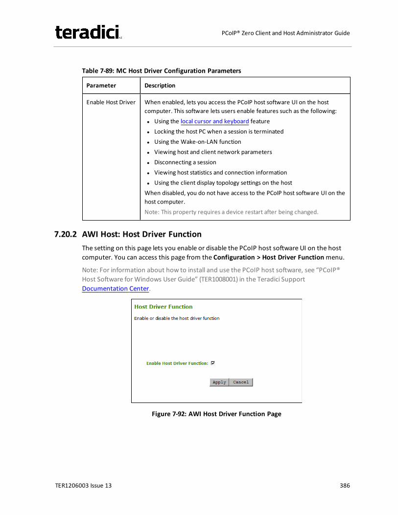
Table 7-89: MC Host Driver Configuration Parameters
Parameter Description
Enable Host Driver When enabled, lets you access the PCoIP host software UI on the hostcomputer. This software lets users enable features such as the following:l Using the local cursor and keyboard featurel Locking the host PC when a session is terminatedl Using the Wake-on-LAN functionl Viewing host and client network parametersl Disconnecting a sessionl Viewing host statistics and connection informationl Using the client display topology settings on the hostWhen disabled, you do not have access to the PCoIP host software UI on thehost computer.Note: This property requires a device restart after being changed.
7.20.2 AWI Host: Host Driver FunctionThe setting on this page lets you enable or disable the PCoIP host software UI on the hostcomputer. You can access this page from the Configuration > Host Driver Functionmenu.
Note: For information about how to install and use the PCoIP host software, see “PCoIP®Host Software for Windows User Guide” (TER1008001) in the Teradici SupportDocumentation Center.
Figure 7-92: AWI Host Driver Function Page
TER1206003 Issue 13 386
PCoIP® Zero Client and Host Administrator Guide
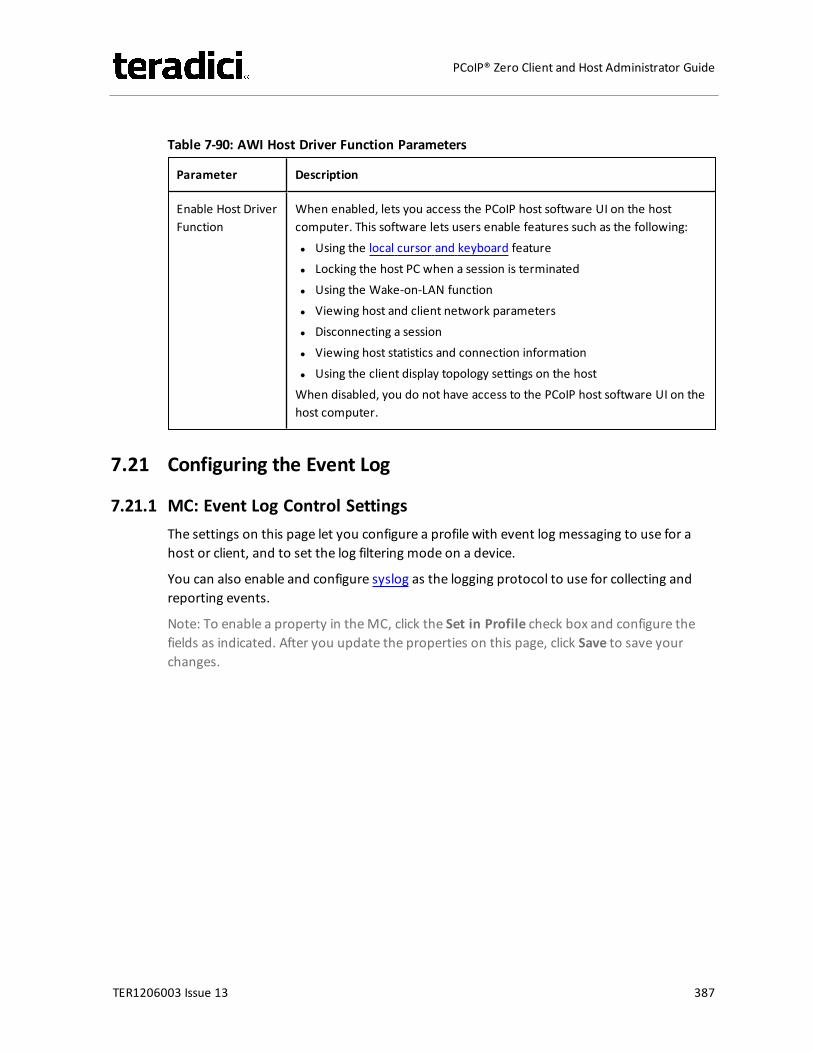
Table 7-90: AWI Host Driver Function Parameters
Parameter Description
Enable Host DriverFunction
When enabled, lets you access the PCoIP host software UI on the hostcomputer. This software lets users enable features such as the following:l Using the local cursor and keyboard featurel Locking the host PC when a session is terminatedl Using the Wake-on-LAN functionl Viewing host and client network parametersl Disconnecting a sessionl Viewing host statistics and connection informationl Using the client display topology settings on the hostWhen disabled, you do not have access to the PCoIP host software UI on thehost computer.
7.21 Configuring the Event Log
7.21.1 MC: Event Log Control SettingsThe settings on this page let you configure a profile with event log messaging to use for ahost or client, and to set the log filtering mode on a device.
You can also enable and configure syslog as the logging protocol to use for collecting andreporting events.
Note: To enable a property in theMC, click the Set in Profile check box and configure thefields as indicated. After you update the properties on this page, click Save to save yourchanges.
TER1206003 Issue 13 387
PCoIP® Zero Client and Host Administrator Guide
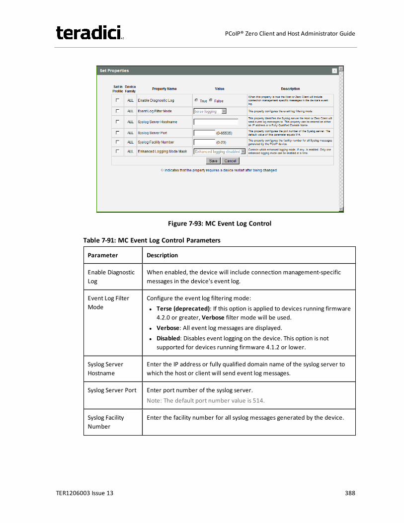
Figure 7-93: MC Event Log Control
Table 7-91: MC Event Log Control Parameters
Parameter Description
Enable DiagnosticLog
When enabled, the device will include connection management-specificmessages in the device's event log.
Event Log FilterMode
Configure the event log filtering mode:l Terse (deprecated): If this option is applied to devices running firmware
4.2.0 or greater, Verbose filter mode will be used.l Verbose: All event log messages are displayed.l Disabled: Disables event logging on the device. This option is not
supported for devices running firmware 4.1.2 or lower.
Syslog ServerHostname
Enter the IP address or fully qualified domain name of the syslog server towhich the host or client will send event log messages.
Syslog Server Port Enter port number of the syslog server.Note: The default port number value is 514.
Syslog FacilityNumber
Enter the facility number for all syslog messages generated by the device.
TER1206003 Issue 13 388
PCoIP® Zero Client and Host Administrator Guide
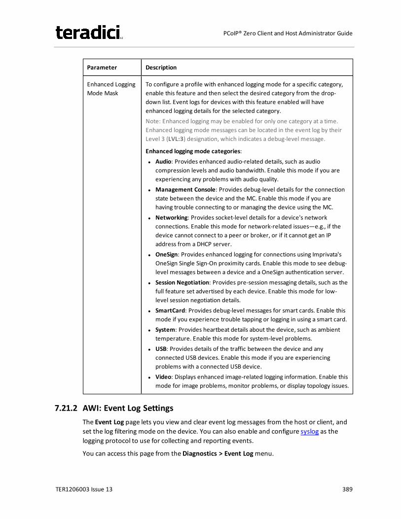
Parameter Description
Enhanced LoggingMode Mask
To configure a profile with enhanced logging mode for a specific category,enable this feature and then select the desired category from the drop-down list. Event logs for devices with this feature enabled will haveenhanced logging details for the selected category.Note: Enhanced logging may be enabled for only one category at a time.Enhanced logging mode messages can be located in the event log by theirLevel 3 (LVL:3) designation, which indicates a debug-level message.
Enhanced logging mode categories:l Audio: Provides enhanced audio-related details, such as audio
compression levels and audio bandwidth. Enable this mode if you areexperiencing any problems with audio quality.
l Management Console: Provides debug-level details for the connectionstate between the device and the MC. Enable this mode if you arehaving trouble connecting to or managing the device using the MC.
l Networking: Provides socket-level details for a device's networkconnections. Enable this mode for network-related issues—e.g., if thedevice cannot connect to a peer or broker, or if it cannot get an IPaddress from a DHCP server.
l OneSign: Provides enhanced logging for connections using Imprivata'sOneSign Single Sign-On proximity cards. Enable this mode to see debug-level messages between a device and a OneSign authentication server.
l Session Negotiation: Provides pre-session messaging details, such as thefull feature set advertised by each device. Enable this mode for low-level session negotiation details.
l SmartCard: Provides debug-level messages for smart cards. Enable thismode if you experience trouble tapping or logging in using a smart card.
l System: Provides heartbeat details about the device, such as ambienttemperature. Enable this mode for system-level problems.
l USB: Provides details of the traffic between the device and anyconnected USB devices. Enable this mode if you are experiencingproblems with a connected USB device.
l Video: Displays enhanced image-related logging information. Enable thismode for image problems, monitor problems, or display topology issues.
7.21.2 AWI: Event Log SettingsThe Event Log page lets you view and clear event log messages from the host or client, andset the log filtering mode on the device. You can also enable and configure syslog as thelogging protocol to use for collecting and reporting events.
You can access this page from theDiagnostics > Event Logmenu.
TER1206003 Issue 13 389
PCoIP® Zero Client and Host Administrator Guide
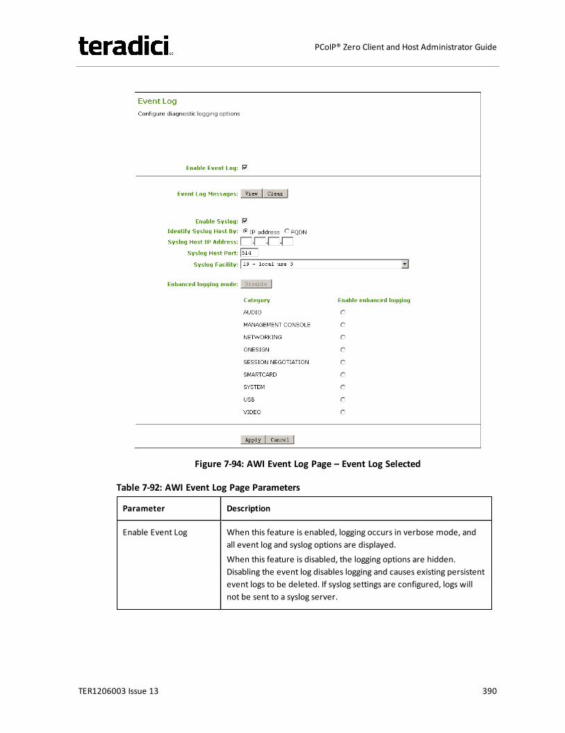
Figure 7-94: AWI Event Log Page – Event Log Selected
Table 7-92: AWI Event Log Page Parameters
Parameter Description
Enable Event Log When this feature is enabled, logging occurs in verbose mode, andall event log and syslog options are displayed.When this feature is disabled, the logging options are hidden.Disabling the event log disables logging and causes existing persistentevent logs to be deleted. If syslog settings are configured, logs willnot be sent to a syslog server.
TER1206003 Issue 13 390
PCoIP® Zero Client and Host Administrator Guide
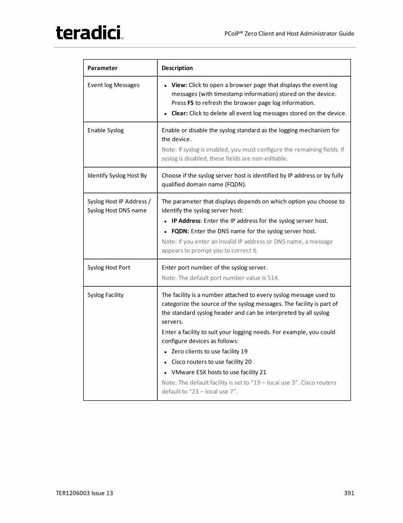
Parameter Description
Event log Messages l View: Click to open a browser page that displays the event logmessages (with timestamp information) stored on the device.Press F5 to refresh the browser page log information.
l Clear: Click to delete all event log messages stored on the device.
Enable Syslog Enable or disable the syslog standard as the logging mechanism forthe device.Note: If syslog is enabled, you must configure the remaining fields. Ifsyslog is disabled, these fields are non-editable.
Identify Syslog Host By Choose if the syslog server host is identified by IP address or by fullyqualified domain name (FQDN).
Syslog Host IP Address /Syslog Host DNS name
The parameter that displays depends on which option you choose toidentify the syslog server host:l IP Address: Enter the IP address for the syslog server host.l FQDN: Enter the DNS name for the syslog server host.Note: If you enter an invalid IP address or DNS name, a messageappears to prompt you to correct it.
Syslog Host Port Enter port number of the syslog server.Note: The default port number value is 514.
Syslog Facility The facility is a number attached to every syslog message used tocategorize the source of the syslog messages. The facility is part ofthe standard syslog header and can be interpreted by all syslogservers.Enter a facility to suit your logging needs. For example, you couldconfigure devices as follows:l Zero clients to use facility 19l Cisco routers to use facility 20l VMware ESX hosts to use facility 21Note: The default facility is set to “19 – local use 3”. Cisco routersdefault to “23 – local use 7”.
TER1206003 Issue 13 391
PCoIP® Zero Client and Host Administrator Guide
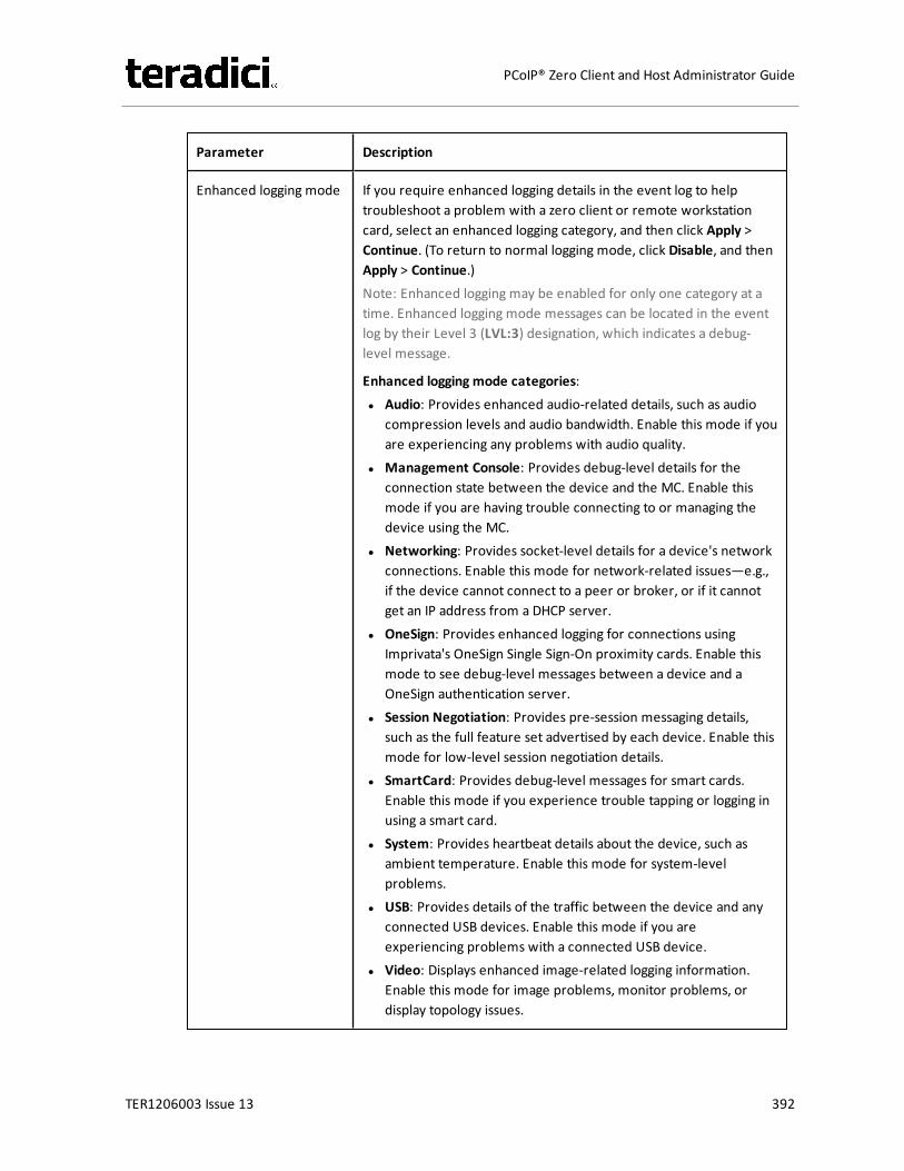
Parameter Description
Enhanced logging mode If you require enhanced logging details in the event log to helptroubleshoot a problem with a zero client or remote workstationcard, select an enhanced logging category, and then click Apply >Continue. (To return to normal logging mode, click Disable, and thenApply > Continue.)Note: Enhanced logging may be enabled for only one category at atime. Enhanced logging mode messages can be located in the eventlog by their Level 3 (LVL:3) designation, which indicates a debug-level message.
Enhanced logging mode categories:l Audio: Provides enhanced audio-related details, such as audio
compression levels and audio bandwidth. Enable this mode if youare experiencing any problems with audio quality.
l Management Console: Provides debug-level details for theconnection state between the device and the MC. Enable thismode if you are having trouble connecting to or managing thedevice using the MC.
l Networking: Provides socket-level details for a device's networkconnections. Enable this mode for network-related issues—e.g.,if the device cannot connect to a peer or broker, or if it cannotget an IP address from a DHCP server.
l OneSign: Provides enhanced logging for connections usingImprivata's OneSign Single Sign-On proximity cards. Enable thismode to see debug-level messages between a device and aOneSign authentication server.
l Session Negotiation: Provides pre-session messaging details,such as the full feature set advertised by each device. Enable thismode for low-level session negotiation details.
l SmartCard: Provides debug-level messages for smart cards.Enable this mode if you experience trouble tapping or logging inusing a smart card.
l System: Provides heartbeat details about the device, such asambient temperature. Enable this mode for system-levelproblems.
l USB: Provides details of the traffic between the device and anyconnected USB devices. Enable this mode if you areexperiencing problems with a connected USB device.
l Video: Displays enhanced image-related logging information.Enable this mode for image problems, monitor problems, ordisplay topology issues.
TER1206003 Issue 13 392
PCoIP® Zero Client and Host Administrator Guide
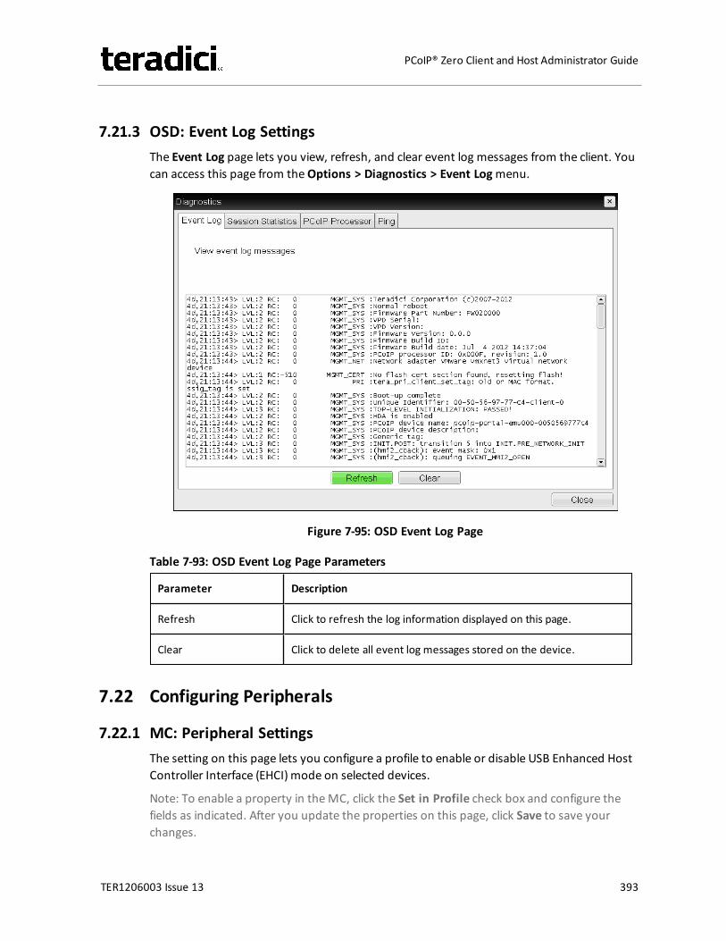
7.21.3 OSD: Event Log SettingsThe Event Log page lets you view, refresh, and clear event log messages from the client. Youcan access this page from theOptions > Diagnostics > Event Logmenu.
Figure 7-95: OSD Event Log Page
Table 7-93: OSD Event Log Page Parameters
Parameter Description
Refresh Click to refresh the log information displayed on this page.
Clear Click to delete all event log messages stored on the device.
7.22 Configuring Peripherals
7.22.1 MC: Peripheral SettingsThe setting on this page lets you configure a profile to enable or disable USB Enhanced HostController Interface (EHCI) mode on selected devices.
Note: To enable a property in theMC, click the Set in Profile check box and configure thefields as indicated. After you update the properties on this page, click Save to save yourchanges.
TER1206003 Issue 13 393
PCoIP® Zero Client and Host Administrator Guide
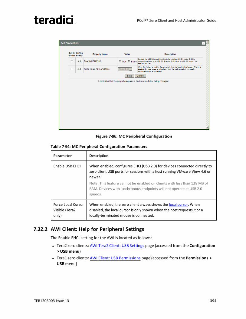
Figure 7-96: MC Peripheral Configuration
Table 7-94: MC Peripheral Configuration Parameters
Parameter Description
Enable USB EHCI When enabled, configures EHCI (USB 2.0) for devices connected directly tozero client USB ports for sessions with a host running VMware View 4.6 ornewer.Note: This feature cannot be enabled on clients with less than 128 MB ofRAM. Devices with isochronous endpoints will not operate at USB 2.0speeds.
Force Local CursorVisible (Tera2only)
When enabled, the zero client always shows the local cursor. Whendisabled, the local cursor is only shown when the host requests it or alocally-terminated mouse is connected.
7.22.2 AWI Client: Help for Peripheral SettingsThe Enable EHCI setting for the AWI is located as follows:
l Tera2 zero clients: AWI Tera2 Client: USB Settings page (accessed from the Configuration> USB menu)
l Tera1 zero clients: AWI Client: USB Permissions page (accessed from the Permissions >USBmenu)
TER1206003 Issue 13 394
PCoIP® Zero Client and Host Administrator Guide
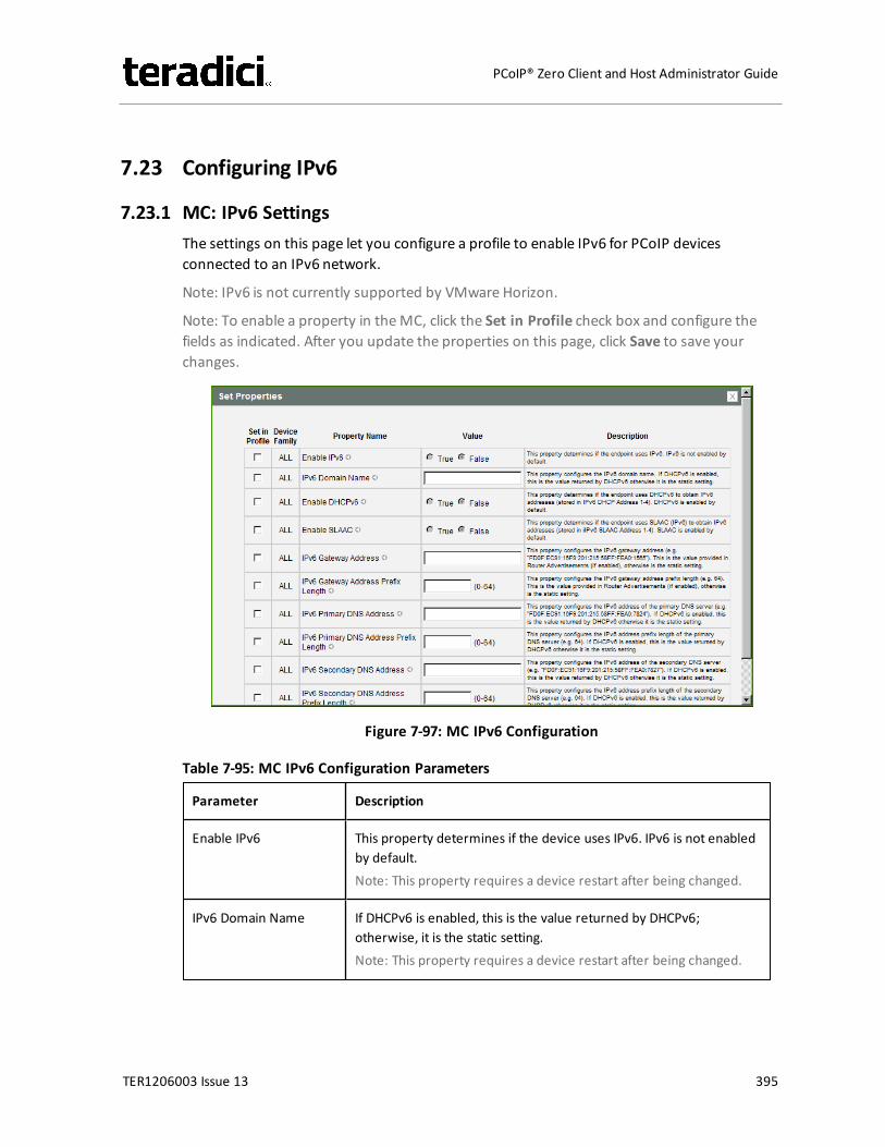
7.23 Configuring IPv6
7.23.1 MC: IPv6 SettingsThe settings on this page let you configure a profile to enable IPv6 for PCoIP devicesconnected to an IPv6 network.
Note: IPv6 is not currently supported by VMware Horizon.
Note: To enable a property in theMC, click the Set in Profile check box and configure thefields as indicated. After you update the properties on this page, click Save to save yourchanges.
Figure 7-97: MC IPv6 Configuration
Table 7-95: MC IPv6 Configuration Parameters
Parameter Description
Enable IPv6 This property determines if the device uses IPv6. IPv6 is not enabledby default.Note: This property requires a device restart after being changed.
IPv6 Domain Name If DHCPv6 is enabled, this is the value returned by DHCPv6;otherwise, it is the static setting.Note: This property requires a device restart after being changed.
TER1206003 Issue 13 395
PCoIP® Zero Client and Host Administrator Guide
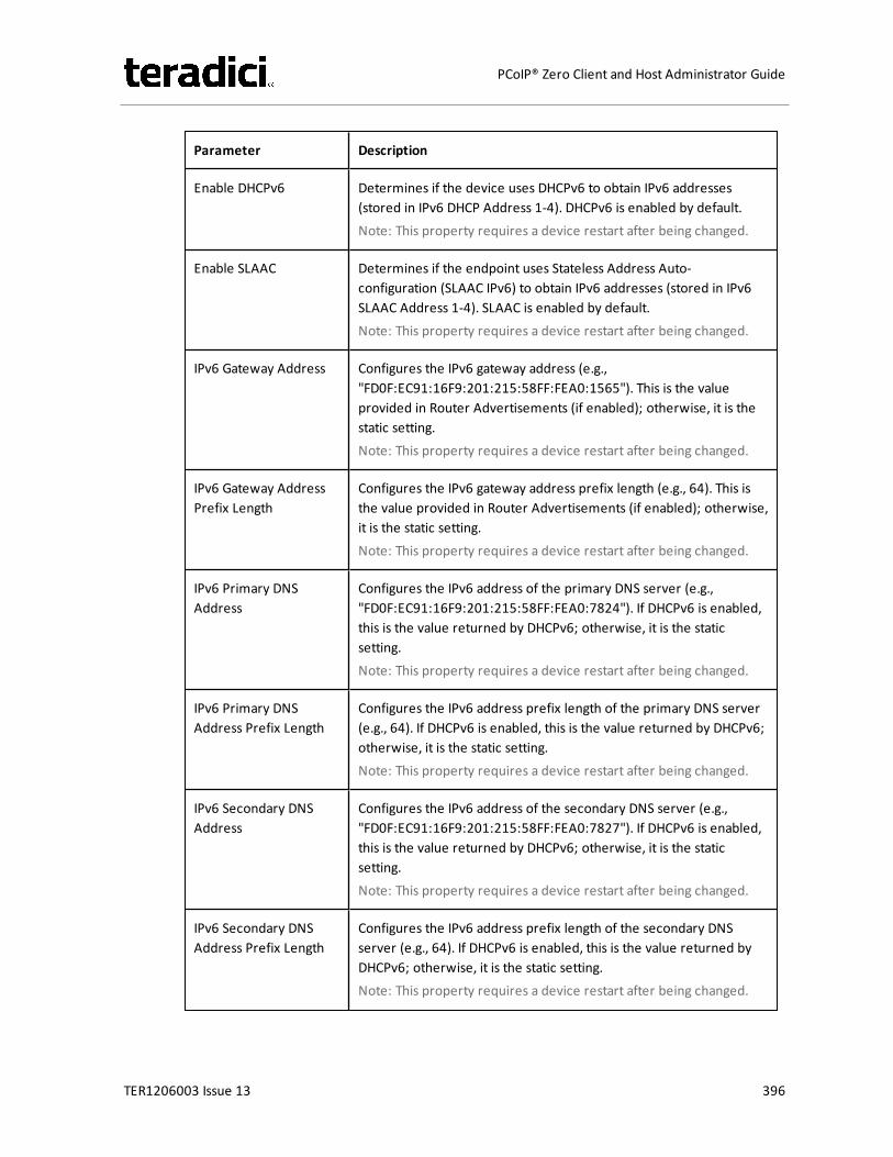
Parameter Description
Enable DHCPv6 Determines if the device uses DHCPv6 to obtain IPv6 addresses(stored in IPv6 DHCP Address 1-4). DHCPv6 is enabled by default.Note: This property requires a device restart after being changed.
Enable SLAAC Determines if the endpoint uses Stateless Address Auto-configuration (SLAAC IPv6) to obtain IPv6 addresses (stored in IPv6SLAAC Address 1-4). SLAAC is enabled by default.Note: This property requires a device restart after being changed.
IPv6 Gateway Address Configures the IPv6 gateway address (e.g.,"FD0F:EC91:16F9:201:215:58FF:FEA0:1565"). This is the valueprovided in Router Advertisements (if enabled); otherwise, it is thestatic setting.Note: This property requires a device restart after being changed.
IPv6 Gateway AddressPrefix Length
Configures the IPv6 gateway address prefix length (e.g., 64). This isthe value provided in Router Advertisements (if enabled); otherwise,it is the static setting.Note: This property requires a device restart after being changed.
IPv6 Primary DNSAddress
Configures the IPv6 address of the primary DNS server (e.g.,"FD0F:EC91:16F9:201:215:58FF:FEA0:7824"). If DHCPv6 is enabled,this is the value returned by DHCPv6; otherwise, it is the staticsetting.Note: This property requires a device restart after being changed.
IPv6 Primary DNSAddress Prefix Length
Configures the IPv6 address prefix length of the primary DNS server(e.g., 64). If DHCPv6 is enabled, this is the value returned by DHCPv6;otherwise, it is the static setting.Note: This property requires a device restart after being changed.
IPv6 Secondary DNSAddress
Configures the IPv6 address of the secondary DNS server (e.g.,"FD0F:EC91:16F9:201:215:58FF:FEA0:7827"). If DHCPv6 is enabled,this is the value returned by DHCPv6; otherwise, it is the staticsetting.Note: This property requires a device restart after being changed.
IPv6 Secondary DNSAddress Prefix Length
Configures the IPv6 address prefix length of the secondary DNSserver (e.g., 64). If DHCPv6 is enabled, this is the value returned byDHCPv6; otherwise, it is the static setting.Note: This property requires a device restart after being changed.
TER1206003 Issue 13 396
PCoIP® Zero Client and Host Administrator Guide
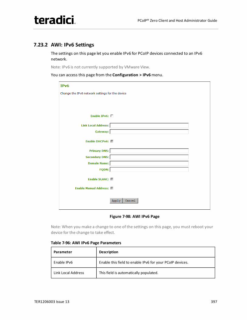
7.23.2 AWI: IPv6 SettingsThe settings on this page let you enable IPv6 for PCoIP devices connected to an IPv6network.
Note: IPv6 is not currently supported by VMware View.
You can access this page from the Configuration > IPv6menu.
Figure 7-98: AWI IPv6 Page
Note: When you make a change to one of the settings on this page, you must reboot yourdevice for the change to take effect.
Table 7-96: AWI IPv6 Page Parameters
Parameter Description
Enable IPv6 Enable this field to enable IPv6 for your PCoIP devices.
Link Local Address This field is automatically populated.
TER1206003 Issue 13 397
PCoIP® Zero Client and Host Administrator Guide
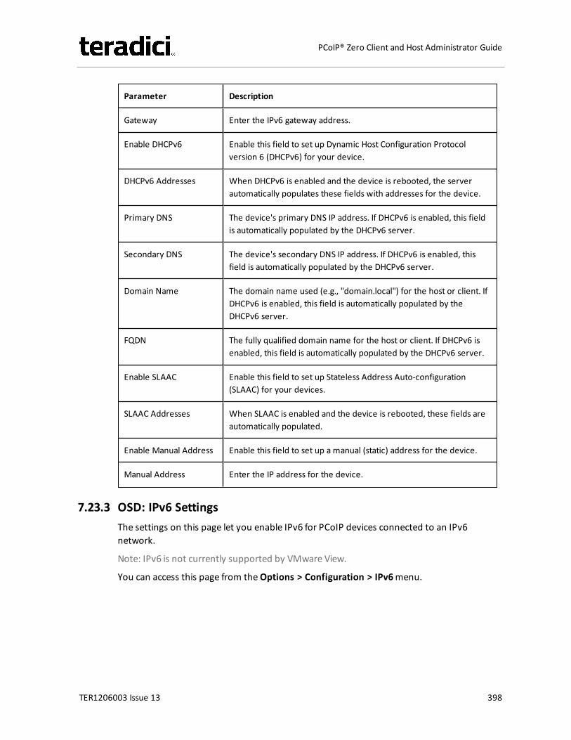
Parameter Description
Gateway Enter the IPv6 gateway address.
Enable DHCPv6 Enable this field to set up Dynamic Host Configuration Protocolversion 6 (DHCPv6) for your device.
DHCPv6 Addresses When DHCPv6 is enabled and the device is rebooted, the serverautomatically populates these fields with addresses for the device.
Primary DNS The device's primary DNS IP address. If DHCPv6 is enabled, this fieldis automatically populated by the DHCPv6 server.
Secondary DNS The device's secondary DNS IP address. If DHCPv6 is enabled, thisfield is automatically populated by the DHCPv6 server.
Domain Name The domain name used (e.g., "domain.local") for the host or client. IfDHCPv6 is enabled, this field is automatically populated by theDHCPv6 server.
FQDN The fully qualified domain name for the host or client. If DHCPv6 isenabled, this field is automatically populated by the DHCPv6 server.
Enable SLAAC Enable this field to set up Stateless Address Auto-configuration(SLAAC) for your devices.
SLAAC Addresses When SLAAC is enabled and the device is rebooted, these fields areautomatically populated.
Enable Manual Address Enable this field to set up a manual (static) address for the device.
Manual Address Enter the IP address for the device.
7.23.3 OSD: IPv6 SettingsThe settings on this page let you enable IPv6 for PCoIP devices connected to an IPv6network.
Note: IPv6 is not currently supported by VMware View.
You can access this page from theOptions > Configuration > IPv6menu.
TER1206003 Issue 13 398
PCoIP® Zero Client and Host Administrator Guide
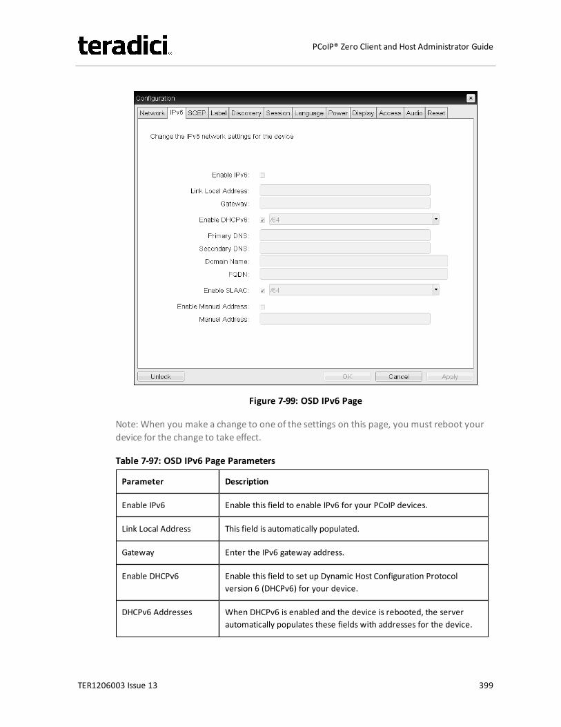
Figure 7-99: OSD IPv6 Page
Note: When you make a change to one of the settings on this page, you must reboot yourdevice for the change to take effect.
Table 7-97: OSD IPv6 Page Parameters
Parameter Description
Enable IPv6 Enable this field to enable IPv6 for your PCoIP devices.
Link Local Address This field is automatically populated.
Gateway Enter the IPv6 gateway address.
Enable DHCPv6 Enable this field to set up Dynamic Host Configuration Protocolversion 6 (DHCPv6) for your device.
DHCPv6 Addresses When DHCPv6 is enabled and the device is rebooted, the serverautomatically populates these fields with addresses for the device.
TER1206003 Issue 13 399
PCoIP® Zero Client and Host Administrator Guide
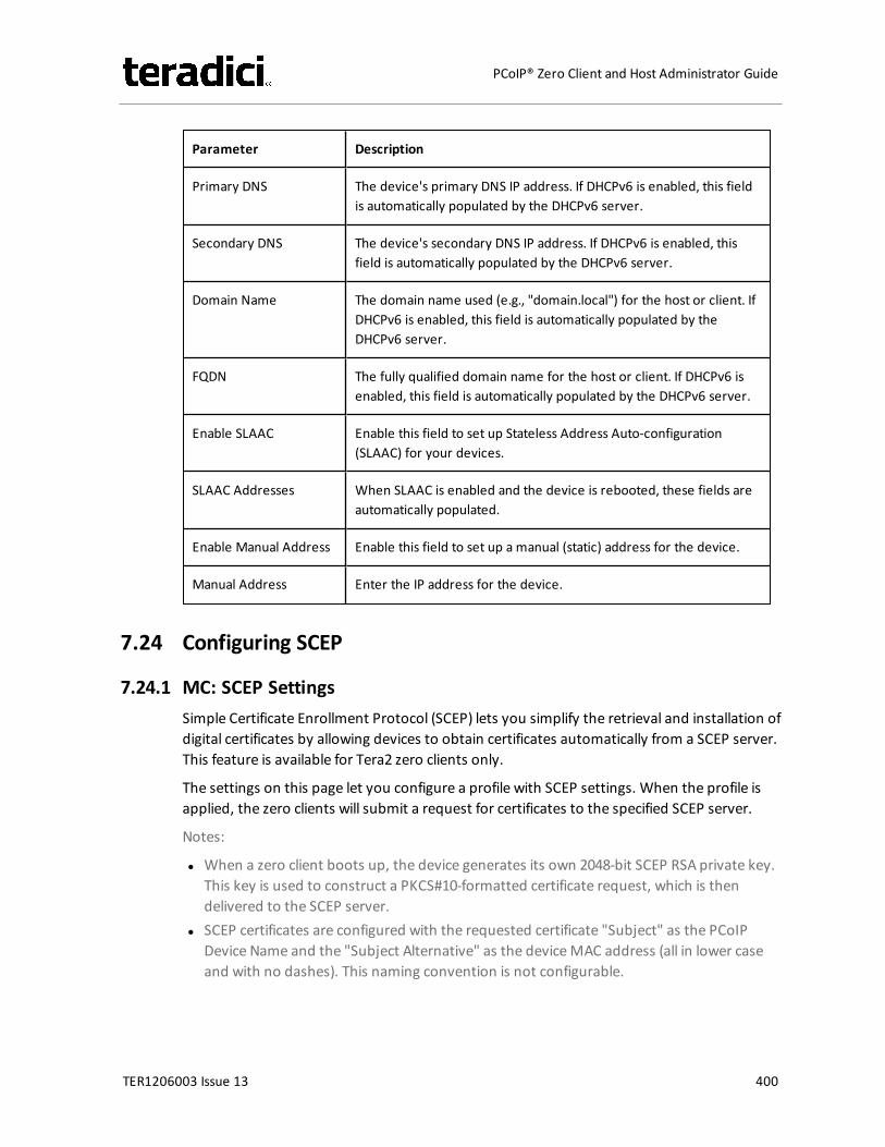
Parameter Description
Primary DNS The device's primary DNS IP address. If DHCPv6 is enabled, this fieldis automatically populated by the DHCPv6 server.
Secondary DNS The device's secondary DNS IP address. If DHCPv6 is enabled, thisfield is automatically populated by the DHCPv6 server.
Domain Name The domain name used (e.g., "domain.local") for the host or client. IfDHCPv6 is enabled, this field is automatically populated by theDHCPv6 server.
FQDN The fully qualified domain name for the host or client. If DHCPv6 isenabled, this field is automatically populated by the DHCPv6 server.
Enable SLAAC Enable this field to set up Stateless Address Auto-configuration(SLAAC) for your devices.
SLAAC Addresses When SLAAC is enabled and the device is rebooted, these fields areautomatically populated.
Enable Manual Address Enable this field to set up a manual (static) address for the device.
Manual Address Enter the IP address for the device.
7.24 Configuring SCEP
7.24.1 MC: SCEP SettingsSimple Certificate Enrollment Protocol (SCEP) lets you simplify the retrieval and installation ofdigital certificates by allowing devices to obtain certificates automatically from a SCEP server.This feature is available for Tera2 zero clients only.
The settings on this page let you configure a profile with SCEP settings. When the profile isapplied, the zero clients will submit a request for certificates to the specified SCEP server.
Notes:
l When a zero client boots up, the device generates its own 2048-bit SCEP RSA private key.This key is used to construct a PKCS#10-formatted certificate request, which is thendelivered to the SCEP server.
l SCEP certificates are configured with the requested certificate "Subject" as the PCoIPDevice Name and the "Subject Alternative" as the deviceMAC address (all in lower caseand with no dashes). This naming convention is not configurable.
TER1206003 Issue 13 400
PCoIP® Zero Client and Host Administrator Guide
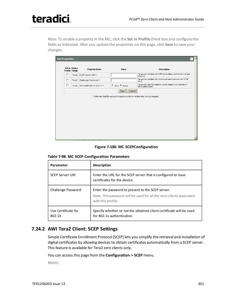
Note: To enable a property in theMC, click the Set in Profile check box and configure thefields as indicated. After you update the properties on this page, click Save to save yourchanges.
Figure 7-100: MC SCEPConfiguration
Table 7-98: MC SCEP Configuration Parameters
Parameter Description
SCEP Server URI Enter the URL for the SCEP server that is configured to issuecertificates for the device.
Challenge Password Enter the password to present to the SCEP server.Note: This password will be used for all the zero clients associatedwith this profile.
Use Certificate for802.1X
Specify whether or not the obtained client certificate will be usedfor 802.1x authentication.
7.24.2 AWI Tera2 Client: SCEP SettingsSimple Certificate Enrollment Protocol (SCEP) lets you simplify the retrieval and installation ofdigital certificates by allowing devices to obtain certificates automatically from a SCEP server.This feature is available for Tera2 zero clients only.
You can access this page from the Configuration > SCEPmenu.
Notes:
TER1206003 Issue 13 401
PCoIP® Zero Client and Host Administrator Guide
l When a zero client boots up, the device generates its own 2048-bit SCEP RSA private key.This key is used to construct a PKCS#10-formatted certificate request, which is thendelivered to the SCEP server.
l SCEP certificates are configured with the requested certificate "Subject" as the PCoIPDevice Name and the "Subject Alternative" as the deviceMAC address (all in lower caseand with no dashes). This naming convention is not configurable.
To retrieve certificates for a device, enter the URL and password for the SCEP server, andthen click Request Certificates. Root CA and 802.1x certificates display after these certificatesare installed.
Figure 7-101: AWI SCEP Page
Table 7-99: AWI SCEP Parameters
Parameter Description
SCEP Server URL Enter the URL for the SCEP server that is configured to issuecertificates for the device.
Challenge Password Enter the password to present to the SCEP server.
Root CA Displays the name of the root CA certificate that has been installed inthe device.
Client Certificate Displays the name of the client certificate that has been installed inthe device.
Request Certificates After entering the SCEP server address and password, click thisbutton to retrieve certificates.
Status Displays the status of the request (e.g., in progress, successful, failed).
TER1206003 Issue 13 402
PCoIP® Zero Client and Host Administrator Guide
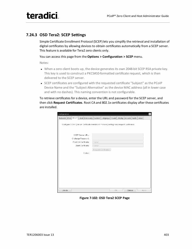
7.24.3 OSD Tera2: SCEP SettingsSimple Certificate Enrollment Protocol (SCEP) lets you simplify the retrieval and installation ofdigital certificates by allowing devices to obtain certificates automatically from a SCEP server.This feature is available for Tera2 zero clients only.
You can access this page from theOptions > Configuration > SCEPmenu.
Notes:
l When a zero client boots up, the device generates its own 2048-bit SCEP RSA private key.This key is used to construct a PKCS#10-formatted certificate request, which is thendelivered to the SCEP server.
l SCEP certificates are configured with the requested certificate "Subject" as the PCoIPDevice Name and the "Subject Alternative" as the deviceMAC address (all in lower caseand with no dashes). This naming convention is not configurable.
To retrieve certificates for a device, enter the URL and password for the SCEP server, andthen click Request Certificates. Root CA and 802.1x certificates display after these certificatesare installed.
Figure 7-102: OSD Tera2 SCEP Page
TER1206003 Issue 13 403
PCoIP® Zero Client and Host Administrator Guide
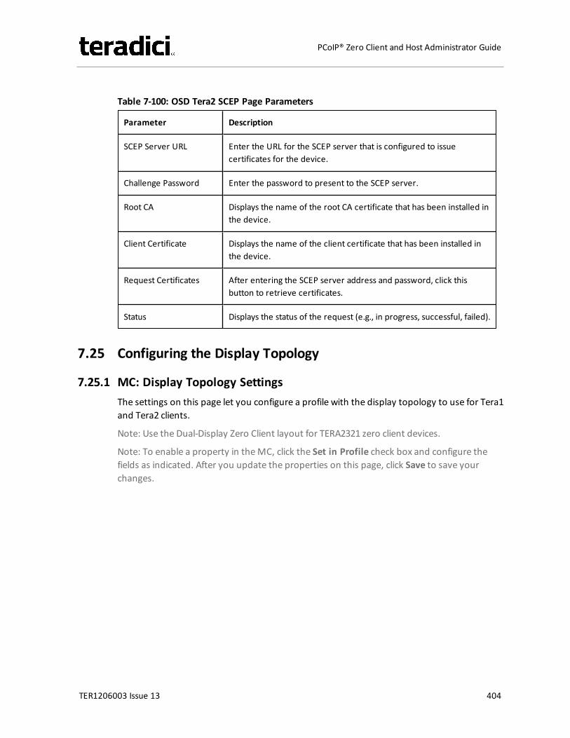
Table 7-100: OSD Tera2 SCEP Page Parameters
Parameter Description
SCEP Server URL Enter the URL for the SCEP server that is configured to issuecertificates for the device.
Challenge Password Enter the password to present to the SCEP server.
Root CA Displays the name of the root CA certificate that has been installed inthe device.
Client Certificate Displays the name of the client certificate that has been installed inthe device.
Request Certificates After entering the SCEP server address and password, click thisbutton to retrieve certificates.
Status Displays the status of the request (e.g., in progress, successful, failed).
7.25 Configuring the Display Topology
7.25.1 MC: Display Topology SettingsThe settings on this page let you configure a profile with the display topology to use for Tera1and Tera2 clients.
Note: Use the Dual-Display Zero Client layout for TERA2321 zero client devices.
Note: To enable a property in theMC, click the Set in Profile check box and configure thefields as indicated. After you update the properties on this page, click Save to save yourchanges.
TER1206003 Issue 13 404
PCoIP® Zero Client and Host Administrator Guide
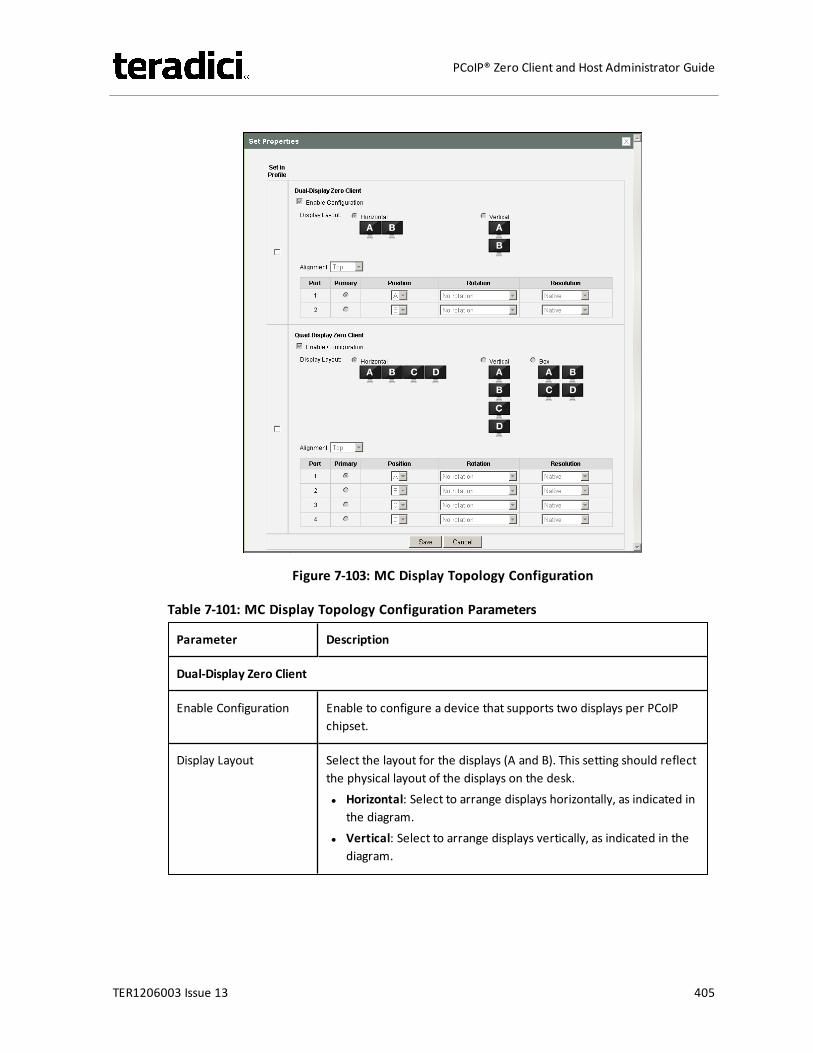
Figure 7-103: MC Display Topology Configuration
Table 7-101: MC Display Topology Configuration Parameters
Parameter Description
Dual-Display Zero Client
Enable Configuration Enable to configure a device that supports two displays per PCoIPchipset.
Display Layout Select the layout for the displays (A and B). This setting should reflectthe physical layout of the displays on the desk.l Horizontal: Select to arrange displays horizontally, as indicated in
the diagram.l Vertical: Select to arrange displays vertically, as indicated in the
diagram.
TER1206003 Issue 13 405
PCoIP® Zero Client and Host Administrator Guide
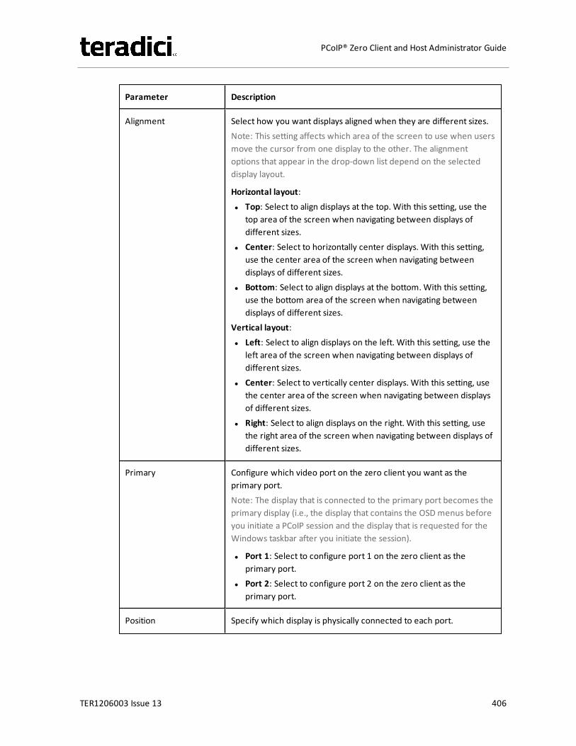
Parameter Description
Alignment Select how you want displays aligned when they are different sizes.Note: This setting affects which area of the screen to use when usersmove the cursor from one display to the other. The alignmentoptions that appear in the drop-down list depend on the selecteddisplay layout.
Horizontal layout:l Top: Select to align displays at the top. With this setting, use the
top area of the screen when navigating between displays ofdifferent sizes.
l Center: Select to horizontally center displays. With this setting,use the center area of the screen when navigating betweendisplays of different sizes.
l Bottom: Select to align displays at the bottom.With this setting,use the bottom area of the screen when navigating betweendisplays of different sizes.
Vertical layout:l Left: Select to align displays on the left. With this setting, use the
left area of the screen when navigating between displays ofdifferent sizes.
l Center: Select to vertically center displays. With this setting, usethe center area of the screen when navigating between displaysof different sizes.
l Right: Select to align displays on the right. With this setting, usethe right area of the screen when navigating between displays ofdifferent sizes.
Primary Configure which video port on the zero client you want as theprimary port.Note: The display that is connected to the primary port becomes theprimary display (i.e., the display that contains the OSD menus beforeyou initiate a PCoIP session and the display that is requested for theWindows taskbar after you initiate the session).
l Port 1: Select to configure port 1 on the zero client as theprimary port.
l Port 2: Select to configure port 2 on the zero client as theprimary port.
Position Specify which display is physically connected to each port.
TER1206003 Issue 13 406
PCoIP® Zero Client and Host Administrator Guide
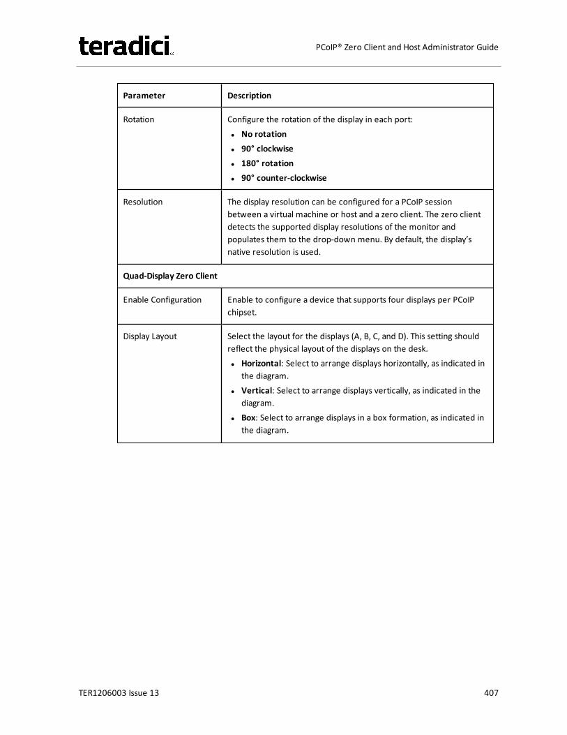
Parameter Description
Rotation Configure the rotation of the display in each port:l No rotationl 90° clockwisel 180° rotationl 90° counter-clockwise
Resolution The display resolution can be configured for a PCoIP sessionbetween a virtual machine or host and a zero client. The zero clientdetects the supported display resolutions of the monitor andpopulates them to the drop-down menu. By default, the display’snative resolution is used.
Quad-Display Zero Client
Enable Configuration Enable to configure a device that supports four displays per PCoIPchipset.
Display Layout Select the layout for the displays (A, B, C, and D). This setting shouldreflect the physical layout of the displays on the desk.l Horizontal: Select to arrange displays horizontally, as indicated in
the diagram.l Vertical: Select to arrange displays vertically, as indicated in the
diagram.l Box: Select to arrange displays in a box formation, as indicated in
the diagram.
TER1206003 Issue 13 407
PCoIP® Zero Client and Host Administrator Guide
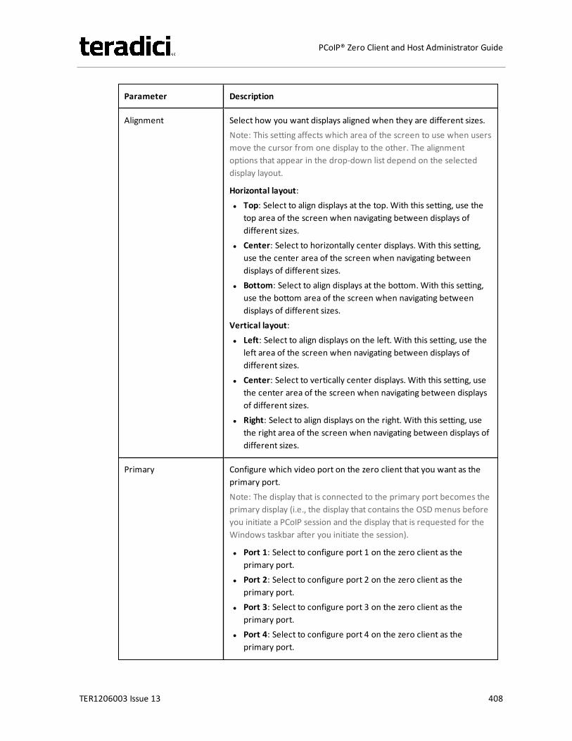
Parameter Description
Alignment Select how you want displays aligned when they are different sizes.Note: This setting affects which area of the screen to use when usersmove the cursor from one display to the other. The alignmentoptions that appear in the drop-down list depend on the selecteddisplay layout.
Horizontal layout:l Top: Select to align displays at the top. With this setting, use the
top area of the screen when navigating between displays ofdifferent sizes.
l Center: Select to horizontally center displays. With this setting,use the center area of the screen when navigating betweendisplays of different sizes.
l Bottom: Select to align displays at the bottom.With this setting,use the bottom area of the screen when navigating betweendisplays of different sizes.
Vertical layout:l Left: Select to align displays on the left. With this setting, use the
left area of the screen when navigating between displays ofdifferent sizes.
l Center: Select to vertically center displays. With this setting, usethe center area of the screen when navigating between displaysof different sizes.
l Right: Select to align displays on the right. With this setting, usethe right area of the screen when navigating between displays ofdifferent sizes.
Primary Configure which video port on the zero client that you want as theprimary port.Note: The display that is connected to the primary port becomes theprimary display (i.e., the display that contains the OSD menus beforeyou initiate a PCoIP session and the display that is requested for theWindows taskbar after you initiate the session).
l Port 1: Select to configure port 1 on the zero client as theprimary port.
l Port 2: Select to configure port 2 on the zero client as theprimary port.
l Port 3: Select to configure port 3 on the zero client as theprimary port.
l Port 4: Select to configure port 4 on the zero client as theprimary port.
TER1206003 Issue 13 408
PCoIP® Zero Client and Host Administrator Guide
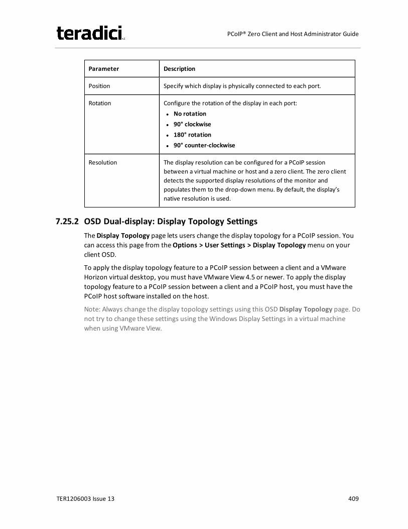
Parameter Description
Position Specify which display is physically connected to each port.
Rotation Configure the rotation of the display in each port:l No rotationl 90° clockwisel 180° rotationl 90° counter-clockwise
Resolution The display resolution can be configured for a PCoIP sessionbetween a virtual machine or host and a zero client. The zero clientdetects the supported display resolutions of the monitor andpopulates them to the drop-down menu. By default, the display’snative resolution is used.
7.25.2 OSD Dual-display: Display Topology SettingsTheDisplay Topology page lets users change the display topology for a PCoIP session. Youcan access this page from theOptions > User Settings > Display Topologymenu on yourclient OSD.
To apply the display topology feature to a PCoIP session between a client and a VMwareHorizon virtual desktop, you must have VMware View 4.5 or newer. To apply the displaytopology feature to a PCoIP session between a client and a PCoIP host, you must have thePCoIP host software installed on the host.
Note: Always change the display topology settings using this OSD Display Topology page. Donot try to change these settings using theWindows Display Settings in a virtual machinewhen using VMware View.
TER1206003 Issue 13 409
PCoIP® Zero Client and Host Administrator Guide
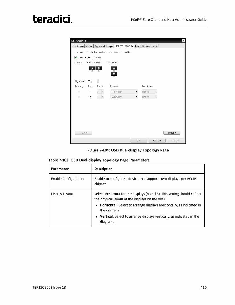
Figure 7-104: OSD Dual-display Topology Page
Table 7-102: OSD Dual-display Topology Page Parameters
Parameter Description
Enable Configuration Enable to configure a device that supports two displays per PCoIPchipset.
Display Layout Select the layout for the displays (A and B). This setting should reflectthe physical layout of the displays on the desk.l Horizontal: Select to arrange displays horizontally, as indicated in
the diagram.l Vertical: Select to arrange displays vertically, as indicated in the
diagram.
TER1206003 Issue 13 410
PCoIP® Zero Client and Host Administrator Guide

Parameter Description
Alignment Select how you want displays aligned when they are different sizes.Note: This setting affects which area of the screen to use when usersmove the cursor from one display to the other. The alignmentoptions that appear in the drop-down list depend on the selecteddisplay layout.
Horizontal layout:l Top: Select to align displays at the top. With this setting, use the
top area of the screen when navigating between displays ofdifferent sizes.
l Center: Select to horizontally center displays. With this setting,use the center area of the screen when navigating betweendisplays of different sizes.
l Bottom: Select to align displays at the bottom.With this setting,use the bottom area of the screen when navigating betweendisplays of different sizes.
Vertical layout:l Left: Select to align displays on the left. With this setting, use the
left area of the screen when navigating between displays ofdifferent sizes.
l Center: Select to vertically center displays. With this setting, usethe center area of the screen when navigating between displaysof different sizes.
l Right: Select to align displays on the right. With this setting, usethe right area of the screen when navigating between displays ofdifferent sizes.
Primary Configure which video port on the zero client you want as theprimary port.Note: The display that is connected to the primary port becomes theprimary display (i.e., the display that contains the OSD menus beforeyou initiate a PCoIP session and the display that is requested for theWindows taskbar after you initiate the session).
l Port 1: Select to configure port 1 on the zero client as theprimary port.
l Port 2: Select to configure port 2 on the zero client as theprimary port.
Position Specify which display is physically connected to each port.
TER1206003 Issue 13 411
PCoIP® Zero Client and Host Administrator Guide
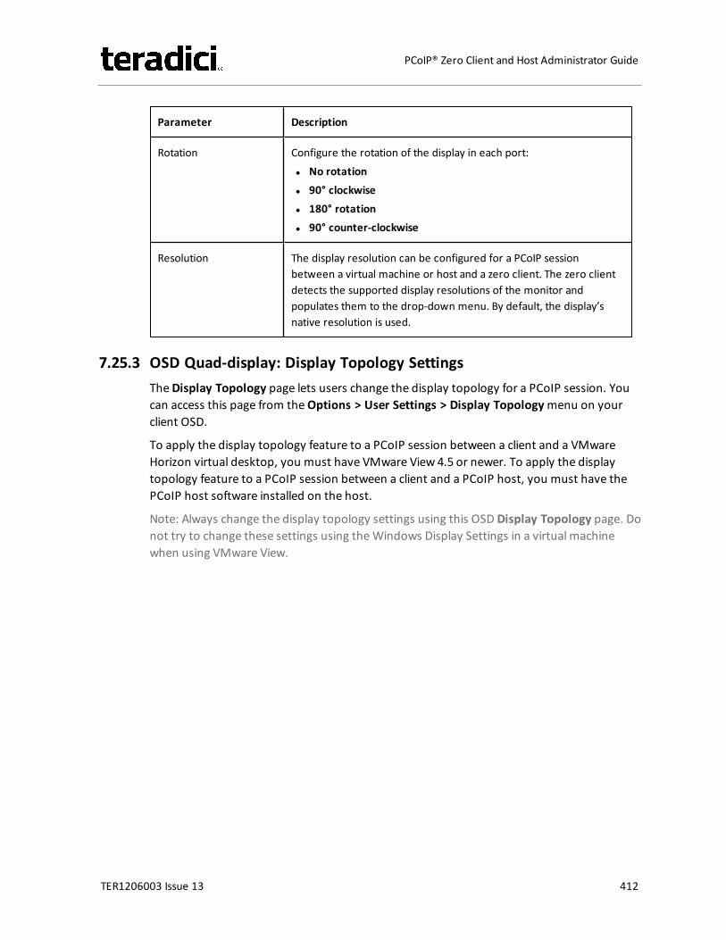
Parameter Description
Rotation Configure the rotation of the display in each port:l No rotationl 90° clockwisel 180° rotationl 90° counter-clockwise
Resolution The display resolution can be configured for a PCoIP sessionbetween a virtual machine or host and a zero client. The zero clientdetects the supported display resolutions of the monitor andpopulates them to the drop-down menu. By default, the display’snative resolution is used.
7.25.3 OSD Quad-display: Display Topology SettingsTheDisplay Topology page lets users change the display topology for a PCoIP session. Youcan access this page from theOptions > User Settings > Display Topologymenu on yourclient OSD.
To apply the display topology feature to a PCoIP session between a client and a VMwareHorizon virtual desktop, you must have VMware View 4.5 or newer. To apply the displaytopology feature to a PCoIP session between a client and a PCoIP host, you must have thePCoIP host software installed on the host.
Note: Always change the display topology settings using this OSD Display Topology page. Donot try to change these settings using theWindows Display Settings in a virtual machinewhen using VMware View.
TER1206003 Issue 13 412
PCoIP® Zero Client and Host Administrator Guide
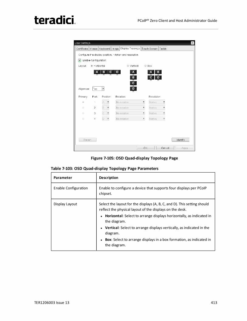
Figure 7-105: OSD Quad-display Topology Page
Table 7-103: OSD Quad-display Topology Page Parameters
Parameter Description
Enable Configuration Enable to configure a device that supports four displays per PCoIPchipset.
Display Layout Select the layout for the displays (A, B, C, and D). This setting shouldreflect the physical layout of the displays on the desk.l Horizontal: Select to arrange displays horizontally, as indicated in
the diagram.l Vertical: Select to arrange displays vertically, as indicated in the
diagram.l Box: Select to arrange displays in a box formation, as indicated in
the diagram.
TER1206003 Issue 13 413
PCoIP® Zero Client and Host Administrator Guide

Parameter Description
Alignment Select how you want displays aligned when they are different sizes.Note: This setting affects which area of the screen to use when usersmove the cursor from one display to the other. The alignmentoptions that appear in the drop-down list depend on the selecteddisplay layout.
Horizontal layout:l Top: Select to align displays at the top. With this setting, use the
top area of the screen when navigating between displays ofdifferent sizes.
l Center: Select to horizontally center displays. With this setting,use the center area of the screen when navigating betweendisplays of different sizes.
l Bottom: Select to align displays at the bottom.With this setting,use the bottom area of the screen when navigating betweendisplays of different sizes.
Vertical layout:l Left: Select to align displays on the left. With this setting, use the
left area of the screen when navigating between displays ofdifferent sizes.
l Center: Select to vertically center displays. With this setting, usethe center area of the screen when navigating between displaysof different sizes.
l Right: Select to align displays on the right. With this setting, usethe right area of the screen when navigating between displays ofdifferent sizes.
Primary Configure which video port on the zero client that you want as theprimary port.Note: The display that is connected to the primary port becomes theprimary display (i.e., the display that contains the OSD menus beforeyou initiate a PCoIP session and the display that is requested for theWindows taskbar after you initiate the session).
l Port 1: Select to configure port 1 on the zero client as theprimary port.
l Port 2: Select to configure port 2 on the zero client as theprimary port.
l Port 3: Select to configure port 3 on the zero client as theprimary port.
l Port 4: Select to configure port 4 on the zero client as theprimary port.
TER1206003 Issue 13 414
PCoIP® Zero Client and Host Administrator Guide
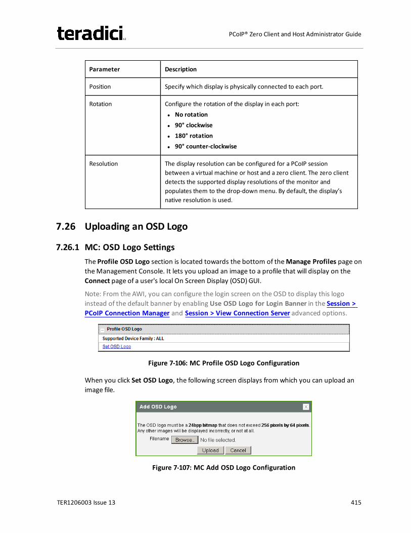
Parameter Description
Position Specify which display is physically connected to each port.
Rotation Configure the rotation of the display in each port:l No rotationl 90° clockwisel 180° rotationl 90° counter-clockwise
Resolution The display resolution can be configured for a PCoIP sessionbetween a virtual machine or host and a zero client. The zero clientdetects the supported display resolutions of the monitor andpopulates them to the drop-down menu. By default, the display’snative resolution is used.
7.26 Uploading an OSD Logo
7.26.1 MC: OSD Logo SettingsThe Profile OSD Logo section is located towards the bottom of theManage Profiles page ontheManagement Console. It lets you upload an image to a profile that will display on theConnect page of a user's local On Screen Display (OSD) GUI.
Note: From the AWI, you can configure the login screen on the OSD to display this logoinstead of the default banner by enabling Use OSD Logo for Login Banner in the Session >PCoIP Connection Manager and Session > View Connection Server advanced options.
Figure 7-106: MC Profile OSD Logo Configuration
When you click Set OSD Logo, the following screen displays from which you can upload animage file.
Figure 7-107: MC Add OSD Logo Configuration
TER1206003 Issue 13 415
PCoIP® Zero Client and Host Administrator Guide
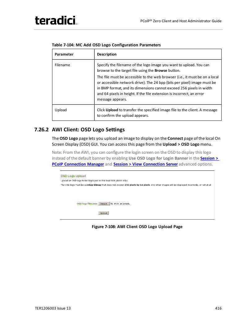
Table 7-104: MC Add OSD Logo Configuration Parameters
Parameter Description
Filename Specify the filename of the logo image you want to upload. You canbrowse to the target file using the Browse button.The file must be accessible to the web browser (i.e., it must be on a localor accessible network drive). The 24 bpp (bits per pixel) image must bein BMP format, and its dimensions cannot exceed 256 pixels in widthand 64 pixels in height. If the file extension is incorrect, an errormessage appears.
Upload Click Upload to transfer the specified image file to the client. A messageto confirm the upload appears.
7.26.2 AWI Client: OSD Logo SettingsTheOSD Logo page lets you upload an image to display on the Connect page of the local OnScreen Display (OSD) GUI. You can access this page from theUpload > OSD Logomenu.
Note: From the AWI, you can configure the login screen on the OSD to display this logoinstead of the default banner by enabling Use OSD Logo for Login Banner in the Session >PCoIP Connection Manager and Session > View Connection Server advanced options.
Figure 7-108: AWI Client OSD Logo Upload Page
TER1206003 Issue 13 416
PCoIP® Zero Client and Host Administrator Guide
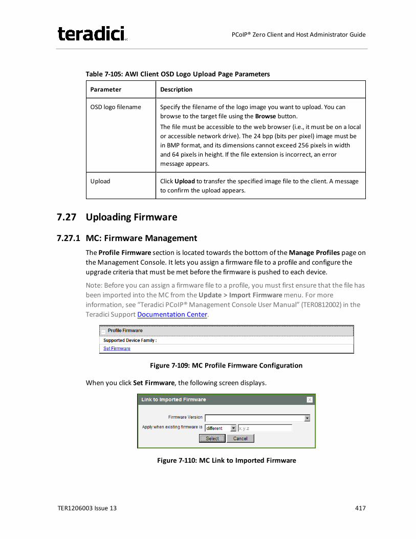
Table 7-105: AWI Client OSD Logo Upload Page Parameters
Parameter Description
OSD logo filename Specify the filename of the logo image you want to upload. You canbrowse to the target file using the Browse button.The file must be accessible to the web browser (i.e., it must be on a localor accessible network drive). The 24 bpp (bits per pixel) image must bein BMP format, and its dimensions cannot exceed 256 pixels in widthand 64 pixels in height. If the file extension is incorrect, an errormessage appears.
Upload Click Upload to transfer the specified image file to the client. A messageto confirm the upload appears.
7.27 Uploading Firmware
7.27.1 MC: Firmware ManagementThe Profile Firmware section is located towards the bottom of theManage Profiles page ontheManagement Console. It lets you assign a firmware file to a profile and configure theupgrade criteria that must bemet before the firmware is pushed to each device.
Note: Before you can assign a firmware file to a profile, you must first ensure that the file hasbeen imported into theMC from theUpdate > Import Firmwaremenu. For moreinformation, see “Teradici PCoIP®Management Console User Manual” (TER0812002) in theTeradici Support Documentation Center.
Figure 7-109: MC Profile Firmware Configuration
When you click Set Firmware, the following screen displays.
Figure 7-110: MC Link to Imported Firmware
TER1206003 Issue 13 417
PCoIP® Zero Client and Host Administrator Guide
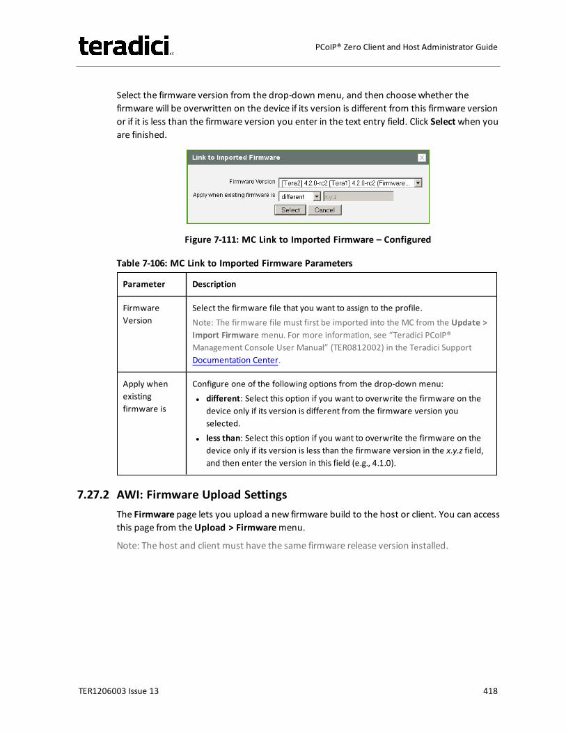
Select the firmware version from the drop-down menu, and then choose whether thefirmware will be overwritten on the device if its version is different from this firmware versionor if it is less than the firmware version you enter in the text entry field. Click Selectwhen youare finished.
Figure 7-111: MC Link to Imported Firmware – Configured
Table 7-106: MC Link to Imported Firmware Parameters
Parameter Description
FirmwareVersion
Select the firmware file that you want to assign to the profile.Note: The firmware file must first be imported into the MC from the Update >Import Firmware menu. For more information, see “Teradici PCoIP®Management Console User Manual” (TER0812002) in the Teradici SupportDocumentation Center.
Apply whenexistingfirmware is
Configure one of the following options from the drop-down menu:l different: Select this option if you want to overwrite the firmware on the
device only if its version is different from the firmware version youselected.
l less than: Select this option if you want to overwrite the firmware on thedevice only if its version is less than the firmware version in the x.y.z field,and then enter the version in this field (e.g., 4.1.0).
7.27.2 AWI: Firmware Upload SettingsThe Firmware page lets you upload a new firmware build to the host or client. You can accessthis page from theUpload > Firmwaremenu.
Note: The host and client must have the same firmware release version installed.
TER1206003 Issue 13 418
PCoIP® Zero Client and Host Administrator Guide
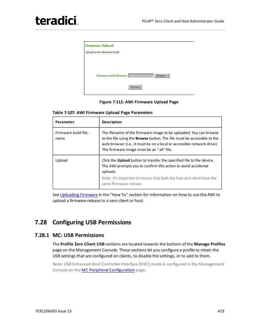
Figure 7-112: AWI Firmware Upload Page
Table 7-107: AWI Firmware Upload Page Parameters
Parameter Description
Firmware build file-name
The filename of the firmware image to be uploaded. You can browseto the file using the Browse button. The file must be accessible to theweb browser (i.e., it must be on a local or accessible network drive).The firmware image must be an ".all" file.
Upload Click the Upload button to transfer the specified file to the device.The AWI prompts you to confirm this action to avoid accidentaluploads.Note: It's important to ensure that both the host and client have thesame firmware release.
See Uploading Firmware in the "How To" section for information on how to use the AWI toupload a firmware release to a zero client or host.
7.28 Configuring USB Permissions
7.28.1 MC: USB PermissionsThe Profile Zero Client USB sections are located towards the bottom of theManage Profilespage on theManagement Console. These sections let you configure a profile to retain theUSB settings that are configured on clients, to disable the settings, or to add to them.
Note: USB Enhanced Host Controller Interface (EHCI) mode is configured in theManagementConsole on theMC Peripheral Configuration page.
TER1206003 Issue 13 419
PCoIP® Zero Client and Host Administrator Guide
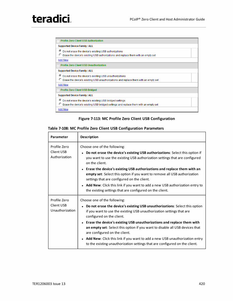
Figure 7-113: MC Profile Zero Client USB Configuration
Table 7-108: MC Profile Zero Client USB Configuration Parameters
Parameter Description
Profile ZeroClient USBAuthorization
Choose one of the following:l Do not erase the device's existing USB authorizations: Select this option if
you want to use the existing USB authorization settings that are configuredon the client.
l Erase the device's existing USB authorizations and replace them with anempty set: Select this option if you want to remove all USB authorizationsettings that are configured on the client.
l Add New: Click this link if you want to add a new USB authorization entry tothe existing settings that are configured on the client.
Profile ZeroClient USBUnauthorization
Choose one of the following:l Do not erase the device's existing USB unauthorizations: Select this option
if you want to use the existing USB unauthorization settings that areconfigured on the client.
l Erase the device's existing USB unauthorizations and replace them withan empty set: Select this option if you want to disable all USB devices thatare configured on the client.
l Add New: Click this link if you want to add a new USB unauthorization entryto the existing unauthorization settings that are configured on the client.
TER1206003 Issue 13 420
PCoIP® Zero Client and Host Administrator Guide
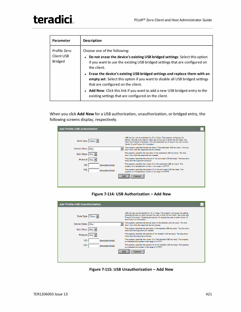
Parameter Description
Profile ZeroClient USBBridged
Choose one of the following:l Do not erase the device's existing USB bridged settings: Select this option
if you want to use the existing USB bridged settings that are configured onthe client.
l Erase the device's existing USB bridged settings and replace them with anempty set: Select this option if you want to disable all USB bridged settingsthat are configured on the client.
l Add New: Click this link if you want to add a new USB bridged entry to theexisting settings that are configured on the client.
When you click Add New for a USB authorization, unauthorization, or bridged entry, thefollowing screens display, respectively.
Figure 7-114: USB Authorization – Add New
Figure 7-115: USB Unauthorization – Add New
TER1206003 Issue 13 421
PCoIP® Zero Client and Host Administrator Guide
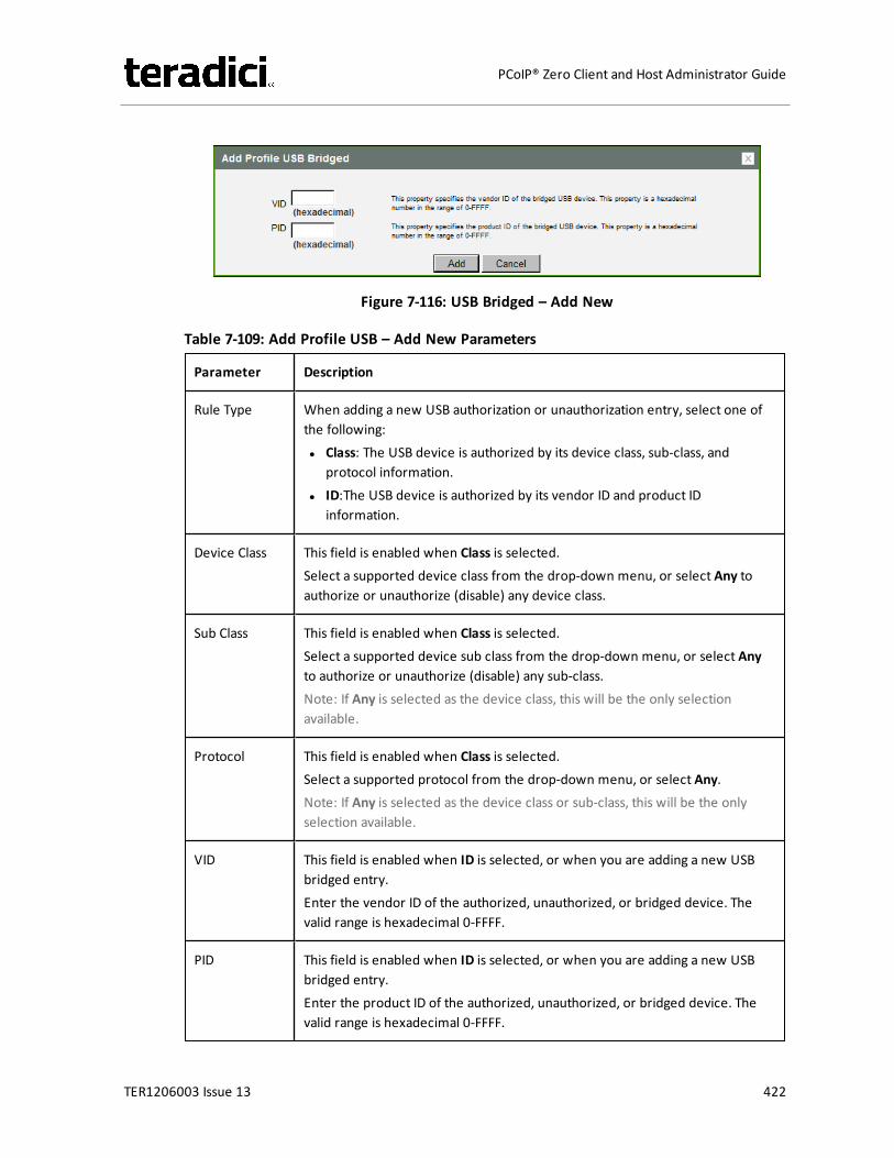
Figure 7-116: USB Bridged – Add New
Table 7-109: Add Profile USB – Add New Parameters
Parameter Description
Rule Type When adding a new USB authorization or unauthorization entry, select one ofthe following:l Class: The USB device is authorized by its device class, sub-class, and
protocol information.l ID:The USB device is authorized by its vendor ID and product ID
information.
Device Class This field is enabled when Class is selected.Select a supported device class from the drop-down menu, or select Any toauthorize or unauthorize (disable) any device class.
Sub Class This field is enabled when Class is selected.Select a supported device sub class from the drop-down menu, or select Anyto authorize or unauthorize (disable) any sub-class.Note: If Any is selected as the device class, this will be the only selectionavailable.
Protocol This field is enabled when Class is selected.Select a supported protocol from the drop-down menu, or select Any.Note: If Any is selected as the device class or sub-class, this will be the onlyselection available.
VID This field is enabled when ID is selected, or when you are adding a new USBbridged entry.Enter the vendor ID of the authorized, unauthorized, or bridged device. Thevalid range is hexadecimal 0-FFFF.
PID This field is enabled when ID is selected, or when you are adding a new USBbridged entry.Enter the product ID of the authorized, unauthorized, or bridged device. Thevalid range is hexadecimal 0-FFFF.
TER1206003 Issue 13 422
PCoIP® Zero Client and Host Administrator Guide
7.28.2 AWI Host: USB PermissionsTheUSB page is accessed from the Permissions > USBmenu. It allows you to authorize a"white list" of USB devices and to unauthorize a "black list" of USB devices based on ID orClass. You can use wildcards (or specify "any") to reduce the number of entries needed todefine all devices.
USB plug events are blocked in the PCoIP zero client hardware for unauthorized USB devices.The host (PCoIP RemoteWorkstation Card or the host virtual desktop) cannot see or accessthe device for an additional layer of security.
TheUSB page is available on the host and client but the host USB permissions have a higherpriority and update the client USB permissions. It is strongly recommended you only set theUSB permissions on the host when connecting to a PCoIP RemoteWorkstation Card. Thefollowing rules apply:
l If the host has permissions programmed (authorized and/or unauthorized), thepermissions are sent to the client. If the client has any unauthorized devices, they areadded to the host's unauthorized devices and the consolidated list is used.
l If the host does not have permissions programmed, the client's permissions are used.
The factory defaults have no USB permissions configured on the host. The factory defaultsfor the client USB permissions are "any, any, any" (that is, authorized USB devices).Depending on the host implementation (for example, hardware PCoIP host or softwarePCoIP host), you can configure the USB permissions as required on the client and/or host.
The host USB permissions are only updated at the start of a PCoIP session. They areauthorized in the following order of priority (from highest to lowest):
l Unauthorized Vendor ID/Product IDl Authorized Vendor ID/Product IDl Unauthorized Device Class/Sub Class/Protocoll Authorized Device Class/Sub Class/Protocol
TER1206003 Issue 13 423
PCoIP® Zero Client and Host Administrator Guide
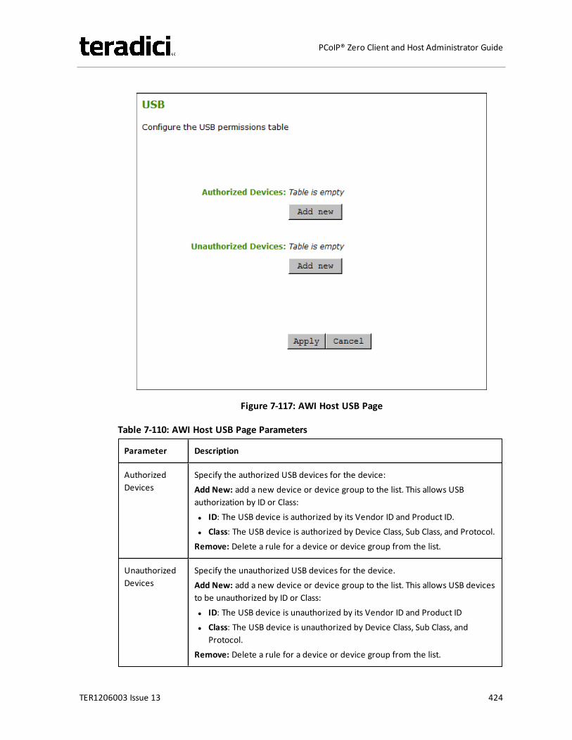
Figure 7-117: AWI Host USB Page
Table 7-110: AWI Host USB Page Parameters
Parameter Description
AuthorizedDevices
Specify the authorized USB devices for the device:Add New: add a new device or device group to the list. This allows USBauthorization by ID or Class:l ID: The USB device is authorized by its Vendor ID and Product ID.l Class: The USB device is authorized by Device Class, Sub Class, and Protocol.Remove: Delete a rule for a device or device group from the list.
UnauthorizedDevices
Specify the unauthorized USB devices for the device.Add New: add a new device or device group to the list. This allows USB devicesto be unauthorized by ID or Class:l ID: The USB device is unauthorized by its Vendor ID and Product IDl Class: The USB device is unauthorized by Device Class, Sub Class, and
Protocol.Remove: Delete a rule for a device or device group from the list.
TER1206003 Issue 13 424
PCoIP® Zero Client and Host Administrator Guide
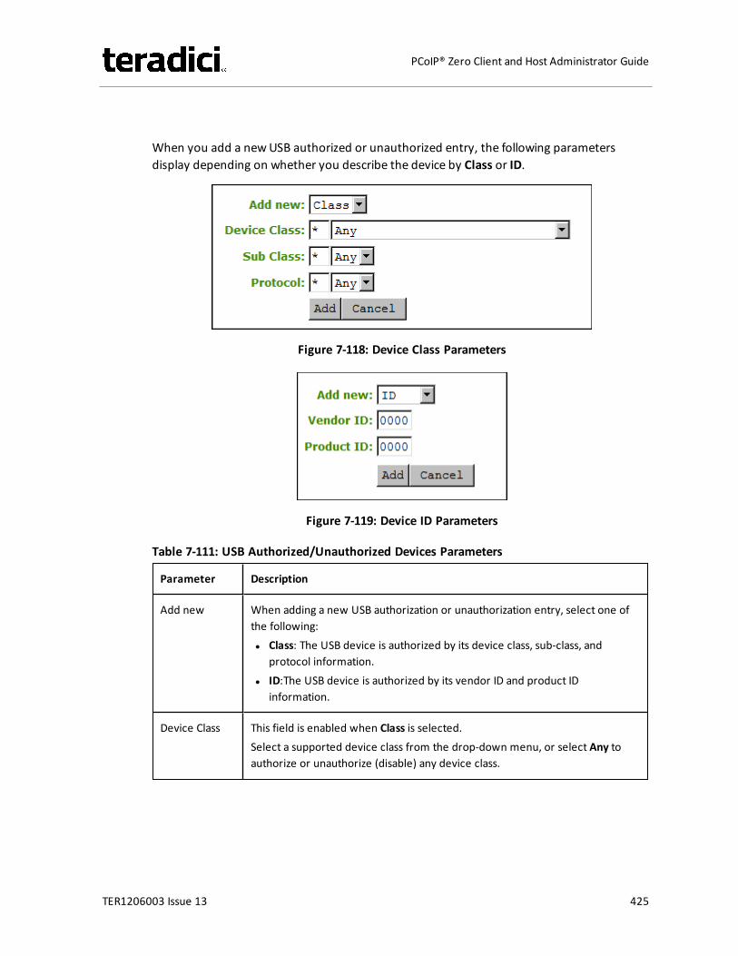
When you add a newUSB authorized or unauthorized entry, the following parametersdisplay depending on whether you describe the device by Class or ID.
Figure 7-118: Device Class Parameters
Figure 7-119: Device ID Parameters
Table 7-111: USB Authorized/Unauthorized Devices Parameters
Parameter Description
Add new When adding a new USB authorization or unauthorization entry, select one ofthe following:l Class: The USB device is authorized by its device class, sub-class, and
protocol information.l ID:The USB device is authorized by its vendor ID and product ID
information.
Device Class This field is enabled when Class is selected.Select a supported device class from the drop-down menu, or select Any toauthorize or unauthorize (disable) any device class.
TER1206003 Issue 13 425
PCoIP® Zero Client and Host Administrator Guide
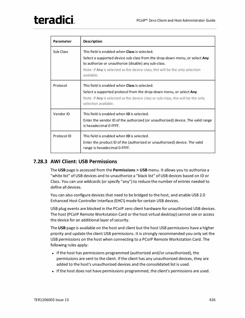
Parameter Description
Sub Class This field is enabled when Class is selected.Select a supported device sub class from the drop-down menu, or select Anyto authorize or unauthorize (disable) any sub-class.Note: If Any is selected as the device class, this will be the only selectionavailable.
Protocol This field is enabled when Class is selected.Select a supported protocol from the drop-down menu, or select Any.Note: If Any is selected as the device class or sub-class, this will be the onlyselection available.
Vendor ID This field is enabled when ID is selected.Enter the vendor ID of the authorized (or unauthorized) device. The valid rangeis hexadecimal 0-FFFF.
Protocol ID This field is enabled when ID is selected.Enter the product ID of the (authorized or unauthorized) device. The validrange is hexadecimal 0-FFFF.
7.28.3 AWI Client: USB PermissionsTheUSB page is accessed from the Permissions > USBmenu. It allows you to authorize a"white list" of USB devices and to unauthorize a "black list" of USB devices based on ID orClass. You can use wildcards (or specify "any") to reduce the number of entries needed todefine all devices.
You can also configure devices that need to be bridged to the host, and enable USB 2.0Enhanced Host Controller Interface (EHCI) mode for certain USB devices.
USB plug events are blocked in the PCoIP zero client hardware for unauthorized USB devices.The host (PCoIP RemoteWorkstation Card or the host virtual desktop) cannot see or accessthe device for an additional layer of security.
TheUSB page is available on the host and client but the host USB permissions have a higherpriority and update the client USB permissions. It is strongly recommended you only set theUSB permissions on the host when connecting to a PCoIP RemoteWorkstation Card. Thefollowing rules apply:
l If the host has permissions programmed (authorized and/or unauthorized), thepermissions are sent to the client. If the client has any unauthorized devices, they areadded to the host's unauthorized devices and the consolidated list is used.
l If the host does not have permissions programmed, the client's permissions are used.
TER1206003 Issue 13 426
PCoIP® Zero Client and Host Administrator Guide
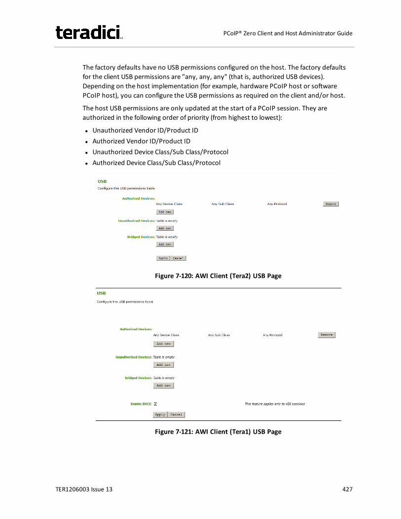
The factory defaults have no USB permissions configured on the host. The factory defaultsfor the client USB permissions are "any, any, any" (that is, authorized USB devices).Depending on the host implementation (for example, hardware PCoIP host or softwarePCoIP host), you can configure the USB permissions as required on the client and/or host.
The host USB permissions are only updated at the start of a PCoIP session. They areauthorized in the following order of priority (from highest to lowest):
l Unauthorized Vendor ID/Product IDl Authorized Vendor ID/Product IDl Unauthorized Device Class/Sub Class/Protocoll Authorized Device Class/Sub Class/Protocol
Figure 7-120: AWI Client (Tera2) USB Page
Figure 7-121: AWI Client (Tera1) USB Page
TER1206003 Issue 13 427
PCoIP® Zero Client and Host Administrator Guide
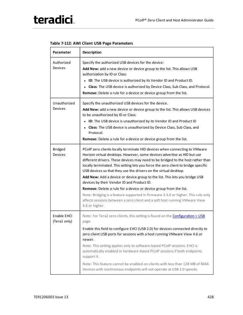
Table 7-112: AWI Client USB Page Parameters
Parameter Description
AuthorizedDevices
Specify the authorized USB devices for the device:Add New: add a new device or device group to the list. This allows USBauthorization by ID or Class:l ID: The USB device is authorized by its Vendor ID and Product ID.l Class: The USB device is authorized by Device Class, Sub Class, and Protocol.Remove: Delete a rule for a device or device group from the list.
UnauthorizedDevices
Specify the unauthorized USB devices for the device.Add New: add a new device or device group to the list. This allows USB devicesto be unauthorized by ID or Class:l ID: The USB device is unauthorized by its Vendor ID and Product IDl Class: The USB device is unauthorized by Device Class, Sub Class, and
Protocol.Remove: Delete a rule for a device or device group from the list.
BridgedDevices
PCoIP zero clients locally terminate HID devices when connecting to VMwareHorizon virtual desktops. However, some devices advertise as HID but usedifferent drivers. These devices may need to be bridged to the host rather thanlocally terminated. This setting lets you force the zero client to bridge specificUSB devices so that they use the drivers on the virtual desktop.Add New: Add a device or device group to the list. This lets you bridge USBdevices by their Vendor ID and Product ID.Remove: Delete a rule for a device or device group from the list.Note: Bridging is a feature supported in firmware 3.3.0 or higher. This rule onlyaffects sessions between a zero client and a soft host running VMware View4.6 or higher.
Enable EHCI(Tera1 only)
Note: For Tera2 zero clients, this setting is found on the Configuration > USBpage.
Enable this field to configure EHCI (USB 2.0) for devices connected directly tozero client USB ports for sessions with a host running VMware View 4.6 ornewer.Note: This setting applies only to software-based PCoIP sessions. EHCI isautomatically enabled in hardware-based PCoIP sessions if both endpointssupport it.
Note: This feature cannot be enabled on clients with less than 128 MB of RAM.Devices with isochronous endpoints will not operate at USB 2.0 speeds.
TER1206003 Issue 13 428
PCoIP® Zero Client and Host Administrator Guide
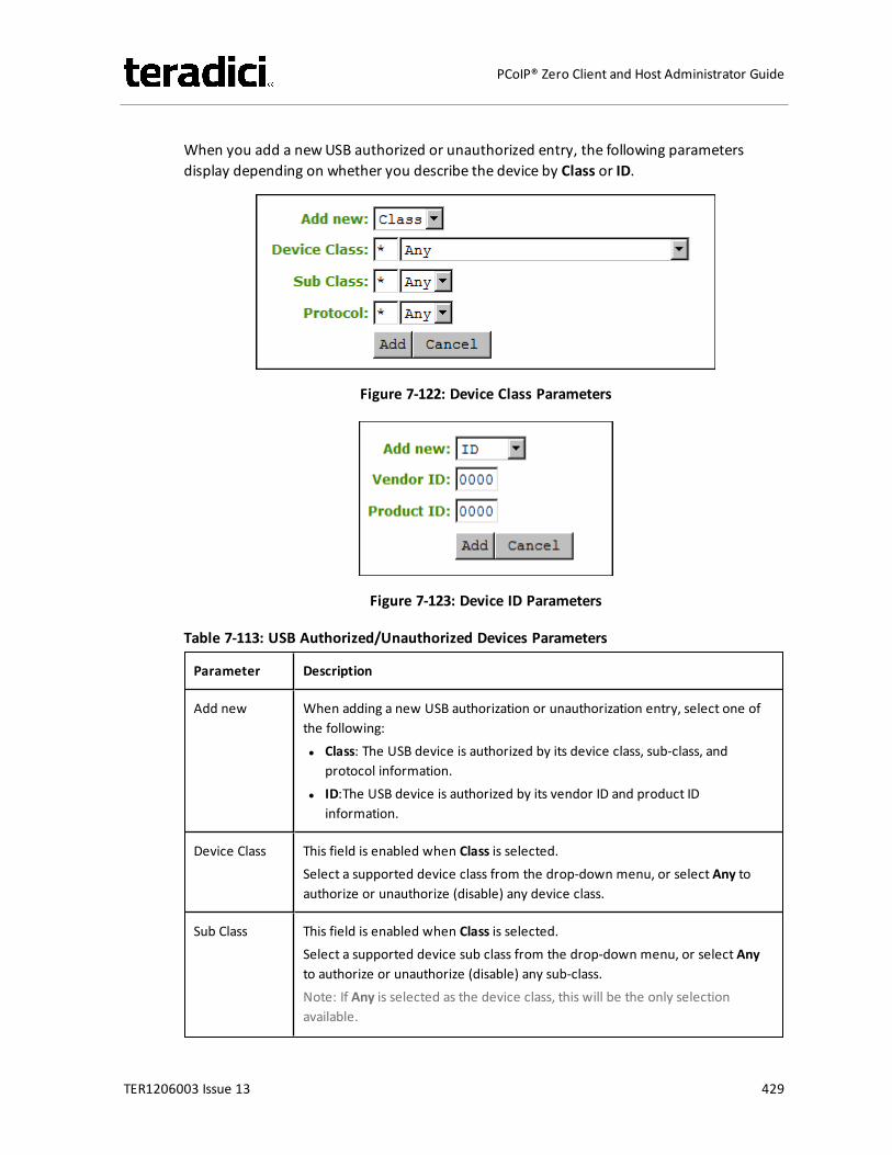
When you add a newUSB authorized or unauthorized entry, the following parametersdisplay depending on whether you describe the device by Class or ID.
Figure 7-122: Device Class Parameters
Figure 7-123: Device ID Parameters
Table 7-113: USB Authorized/Unauthorized Devices Parameters
Parameter Description
Add new When adding a new USB authorization or unauthorization entry, select one ofthe following:l Class: The USB device is authorized by its device class, sub-class, and
protocol information.l ID:The USB device is authorized by its vendor ID and product ID
information.
Device Class This field is enabled when Class is selected.Select a supported device class from the drop-down menu, or select Any toauthorize or unauthorize (disable) any device class.
Sub Class This field is enabled when Class is selected.Select a supported device sub class from the drop-down menu, or select Anyto authorize or unauthorize (disable) any sub-class.Note: If Any is selected as the device class, this will be the only selectionavailable.
TER1206003 Issue 13 429
PCoIP® Zero Client and Host Administrator Guide
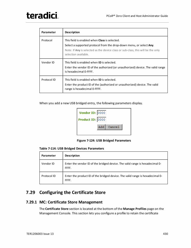
Parameter Description
Protocol This field is enabled when Class is selected.Select a supported protocol from the drop-down menu, or select Any.Note: If Any is selected as the device class or sub-class, this will be the onlyselection available.
Vendor ID This field is enabled when ID is selected.Enter the vendor ID of the authorized (or unauthorized) device. The valid rangeis hexadecimal 0-FFFF.
Protocol ID This field is enabled when ID is selected.Enter the product ID of the (authorized or unauthorized) device. The validrange is hexadecimal 0-FFFF.
When you add a newUSB bridged entry, the following parameters display.
Figure 7-124: USB Bridged Parameters
Table 7-114: USB Bridged Devices Parameters
Parameter Description
Vendor ID Enter the vendor ID of the bridged device. The valid range is hexadecimal 0-FFFF.
Protocol ID Enter the product ID of the bridged device. The valid range is hexadecimal 0-FFFF.
7.29 Configuring the Certificate Store
7.29.1 MC: Certificate Store ManagementThe Certificate Store section is located at the bottom of theManage Profiles page on theManagement Console. This section lets you configure a profile to retain the certificate
TER1206003 Issue 13 430
PCoIP® Zero Client and Host Administrator Guide
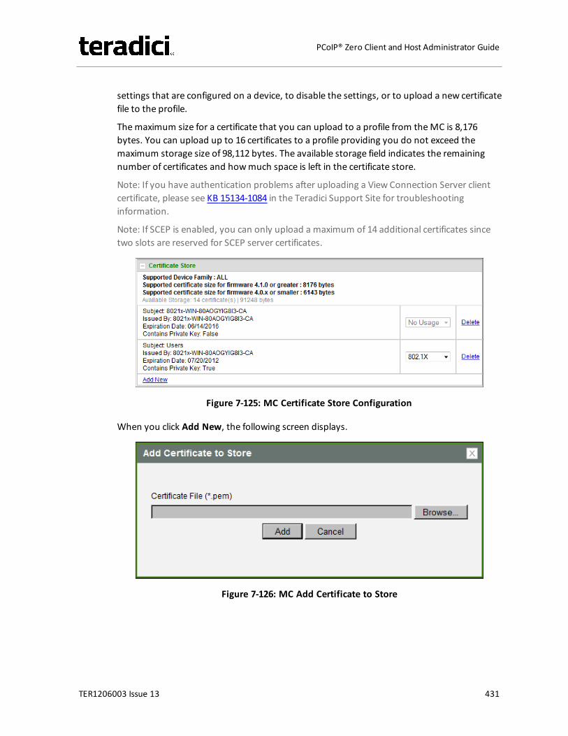
settings that are configured on a device, to disable the settings, or to upload a new certificatefile to the profile.
Themaximum size for a certificate that you can upload to a profile from theMC is 8,176bytes. You can upload up to 16 certificates to a profile providing you do not exceed themaximum storage size of 98,112 bytes. The available storage field indicates the remainingnumber of certificates and howmuch space is left in the certificate store.
Note: If you have authentication problems after uploading a View Connection Server clientcertificate, please see KB 15134-1084 in the Teradici Support Site for troubleshootinginformation.
Note: If SCEP is enabled, you can only upload a maximum of 14 additional certificates sincetwo slots are reserved for SCEP server certificates.
Figure 7-125: MC Certificate Store Configuration
When you click Add New, the following screen displays.
Figure 7-126: MC Add Certificate to Store
TER1206003 Issue 13 431
PCoIP® Zero Client and Host Administrator Guide
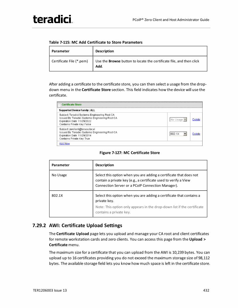
Table 7-115: MC Add Certificate to Store Parameters
Parameter Description
Certificate File (*.pem) Use the Browse button to locate the certificate file, and then clickAdd.
After adding a certificate to the certificate store, you can then select a usage from the drop-down menu in the Certificate Store section. This field indicates how the device will use thecertificate.
Figure 7-127: MC Certificate Store
Parameter Description
No Usage Select this option when you are adding a certificate that does notcontain a private key (e.g., a certificate used to verify a ViewConnection Server or a PCoIP Connection Manager).
802.1X Select this option when you are adding a certificate that contains aprivate key.Note: This option only appears in the drop-down list if the certificatecontains a private key.
7.29.2 AWI: Certificate Upload SettingsThe Certificate Upload page lets you upload and manage your CA root and client certificatesfor remote workstation cards and zero clients. You can access this page from theUpload >Certificatemenu.
Themaximum size for a certificate that you can upload from the AWI is 10,239 bytes. You canupload up to 16 certificates providing you do not exceed themaximum storage size of 98,112bytes. The available storage field lets you know howmuch space is left in the certificate store.
TER1206003 Issue 13 432
PCoIP® Zero Client and Host Administrator Guide
Note: If you have authentication problems after uploading a View Connection Server clientcertificate, please see KB 15134-1084 in the Teradici Support Site for troubleshootinginformation.
Note: If SCEP is enabled, you can only upload a maximum of 14 additional certificates sincetwo slots are reserved for SCEP server certificates.
Note: The PCoIP protocol reads just one 802.1x client certificate for 802.1x compliantnetworks. Make sure you include all the security information for your PCoIP devices in thatclient certificate. For more information about uploading certificates, see KB 15134-1063 in theTeradici Support Site. For information on 802.1x certificate authentication, see Configuring802.1x Network Device Authentication.
The following are some general guidelines when using 802.1x authentication.
l 802.1x authentication requires two certificates—an 802.1x client certificate and an 802.1xserver CA root certificate.
l The 802.1x client certificatemust be in .pem format and contain a private key that usesRSA encryption. If the certificate is in a different format, you must first convert thecertificate, including the private key, to .pem format before uploading it.
l After uploading the 802.1x client certificate from the Certificate Upload page, you mustconfigure 802.1x authentication from theNetwork page. This entails enabling 802.1xauthentication, entering an identity string for the device, selecting the correct 802.1xclient certificate from the drop-down list, and then applying your settings.
l The 802.1x server CA root certificatemust be in .pem format, but should not need tocontain a private key. If the certificate is in a different format, you must convert it to .pemformat before uploading it. This certificate does not require configuration from theNetwork page.
l Both the 802.1x client certificate and the 802.1x server CA root certificatemust be lessthan 10,240 bytes; otherwise, you will not be able to upload them. Some certificate filesmay contain multiple certificates. If your certificate file is too large and it has multiplecertificates within, you can open the file in a text editor, then copy and save eachcertificate to its own file.
TER1206003 Issue 13 433
PCoIP® Zero Client and Host Administrator Guide
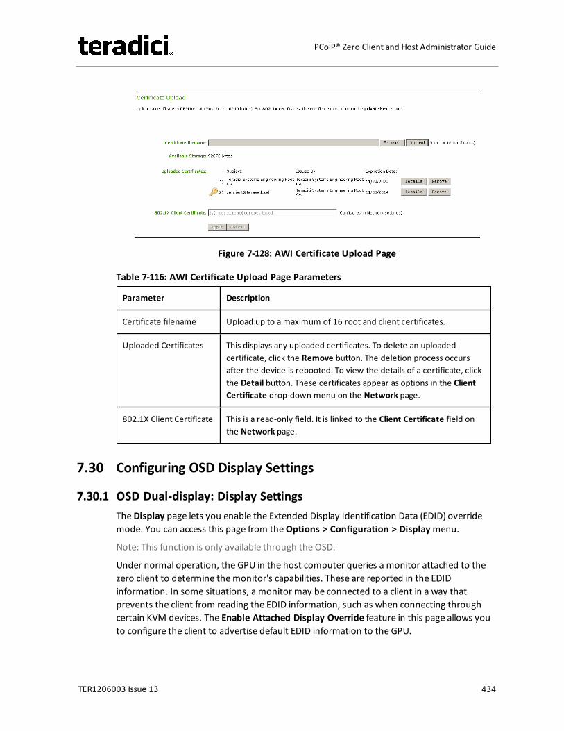
Figure 7-128: AWI Certificate Upload Page
Table 7-116: AWI Certificate Upload Page Parameters
Parameter Description
Certificate filename Upload up to a maximum of 16 root and client certificates.
Uploaded Certificates This displays any uploaded certificates. To delete an uploadedcertificate, click the Remove button. The deletion process occursafter the device is rebooted. To view the details of a certificate, clickthe Detail button. These certificates appear as options in the ClientCertificate drop-down menu on the Network page.
802.1X Client Certificate This is a read-only field. It is linked to the Client Certificate field onthe Network page.
7.30 Configuring OSD Display Settings
7.30.1 OSD Dual-display: Display SettingsTheDisplay page lets you enable the Extended Display Identification Data (EDID) overridemode. You can access this page from theOptions > Configuration > Displaymenu.
Note: This function is only available through the OSD.
Under normal operation, the GPU in the host computer queries a monitor attached to thezero client to determine themonitor's capabilities. These are reported in the EDIDinformation. In some situations, a monitor may be connected to a client in a way thatprevents the client from reading the EDID information, such as when connecting throughcertain KVM devices. The Enable Attached Display Override feature in this page allows youto configure the client to advertise default EDID information to the GPU.
TER1206003 Issue 13 434
PCoIP® Zero Client and Host Administrator Guide
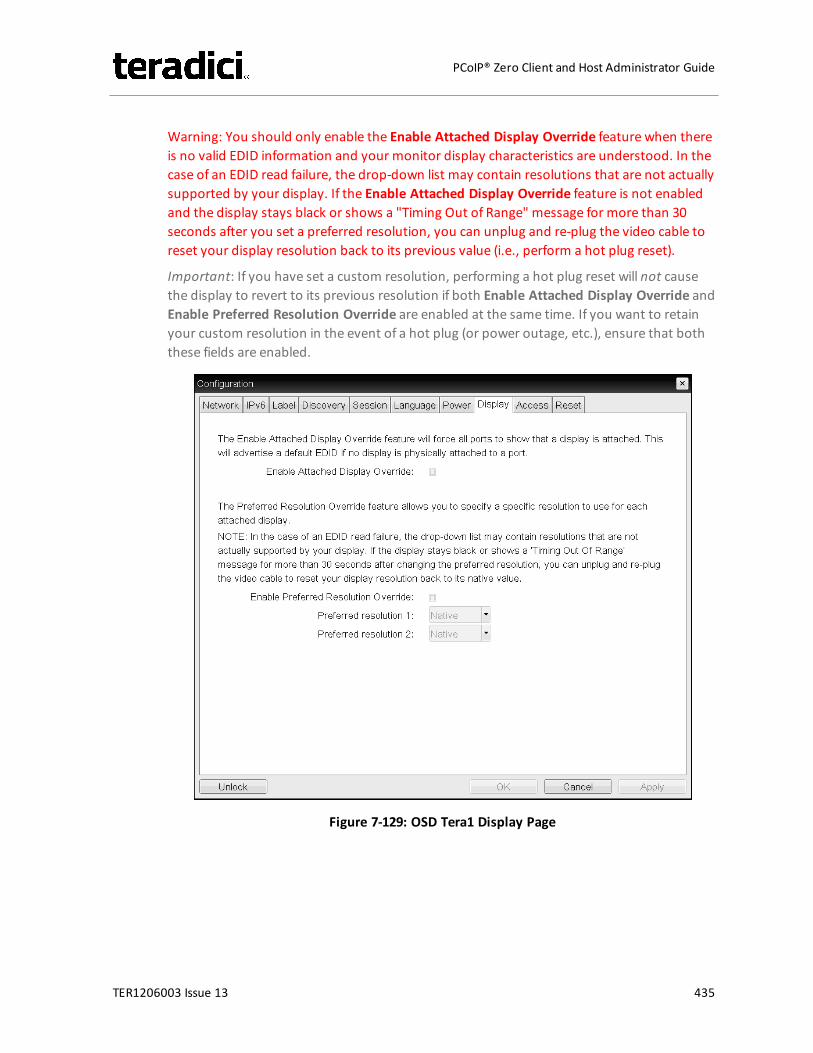
Warning: You should only enable the Enable Attached Display Override feature when thereis no valid EDID information and your monitor display characteristics are understood. In thecase of an EDID read failure, the drop-down list may contain resolutions that are not actuallysupported by your display. If the Enable Attached Display Override feature is not enabledand the display stays black or shows a "Timing Out of Range" message for more than 30seconds after you set a preferred resolution, you can unplug and re-plug the video cable toreset your display resolution back to its previous value (i.e., perform a hot plug reset).
Important: If you have set a custom resolution, performing a hot plug reset will not causethe display to revert to its previous resolution if both Enable Attached Display Override andEnable Preferred Resolution Override are enabled at the same time. If you want to retainyour custom resolution in the event of a hot plug (or power outage, etc.), ensure that boththese fields are enabled.
Figure 7-129: OSD Tera1 Display Page
TER1206003 Issue 13 435
PCoIP® Zero Client and Host Administrator Guide

Table 7-117: OSD Tera1 Display Page Parameters
Parameter Description
Enable Attached DisplayOverride
This option is intended for legacy systems. It configures the client tosend default EDID information to the host when a monitor cannot bedetected or is not attached to the client. In versions of Windowsprior to Windows 7, once the host had no EDID information, it wouldassume no monitors were attached and would never recheck. Thisoption ensures that the host always has EDID information when theclient is in session.The following default resolutions are advertised when this option isenabled:l 2560x1600 @60 Hzl 2048x1152 @60 Hzl 1920x1440 @60 Hzl 1920x1200 @60 Hzl 1920x1080 @60 Hzl 1856x1392 @60 Hzl 1792x1344 @60 Hzl 1680x1050 @60 Hzl 1600x1200 @60 Hzl 1600x900 @60 Hzl 1440x900 @60 Hzl 1400x1050 @60 Hzl 1366x768 @60 Hzl 1360x768 @60 Hzl 1280x1024 @60 Hzl 1280x960 @60 Hzl 1280x800 @60 Hzl 1280x768 @60 Hzl 1280x720 @60 Hzl 1024x768 @60 Hzl 848x480 @60 Hzl 800x600 @60 Hzl 640x480 @60 HzAny displays attached to the client will be set to the native resolutionof 1024x768 when this option is enabled.
TER1206003 Issue 13 436
PCoIP® Zero Client and Host Administrator Guide
Parameter Description
Enable PreferredResolution Override
Enable this option when a display is attached but cannot be detectedby the system, and you want to specify a preferred resolution for thedisplay. The same default list of resolutions as above will beadvertised, except the preferred resolution you configure here for adisplay will be sent as the native resolution instead of the defaultnative resolution of 1024x768.l Preferred resolution 0: Select the preferred resolution of the
display connected to port 1 on the zero client.l Preferred resolution 1: Select the preferred resolution of the
display connected to port 2 on the zero client.Any displays attached to the client will be set to their specifiedpreferred resolutions when this option is enabled.See "Important" note, above, for information on how to retain acustom resolution in the event of a hot plug, power outage, etc.
7.30.2 OSD Quad-display: Display SettingsTheDisplay page lets you enable the Extended Display Identification Data (EDID) overridemode. You can access this page from theOptions > Configuration > Displaymenu.
Note: This function is only available through the OSD.
Under normal operation, the GPU in the host computer queries a monitor attached to thezero client to determine themonitor's capabilities. These are reported in the EDIDinformation. In some situations, a monitor may be connected to a client in a way thatprevents the client from reading the EDID information, such as when connecting throughcertain KVM devices. The Enable Attached Display Override feature in this page allows youto configure the client to advertise default EDID information to the GPU.
Warning: You should only enable the Enable Attached Display Override feature when thereis no valid EDID information and your monitor display characteristics are understood. In thecase of an EDID read failure, the drop-down list may contain resolutions that are not actuallysupported by your display. If the Enable Attached Display Override feature is not enabledand the display stays black or shows a "Timing Out of Range" message for more than 30seconds after you set a preferred resolution, you can unplug and re-plug the video cable toreset your display resolution back to its previous value (i.e., perform a hot plug reset).
Important: If you have set a custom resolution, performing a hot plug reset will not causethe display to revert to its previous resolution if both Enable Attached Display Override andEnable Preferred Resolution Override are enabled at the same time. If you want to retainyour custom resolution in the event of a hot plug (or power outage, etc.), ensure that boththese fields are enabled.
TER1206003 Issue 13 437
PCoIP® Zero Client and Host Administrator Guide
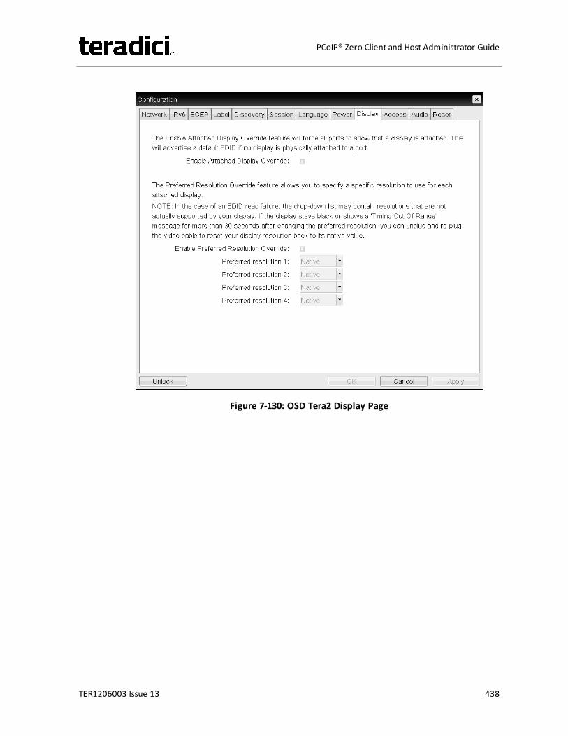
Figure 7-130: OSD Tera2 Display Page
TER1206003 Issue 13 438
PCoIP® Zero Client and Host Administrator Guide
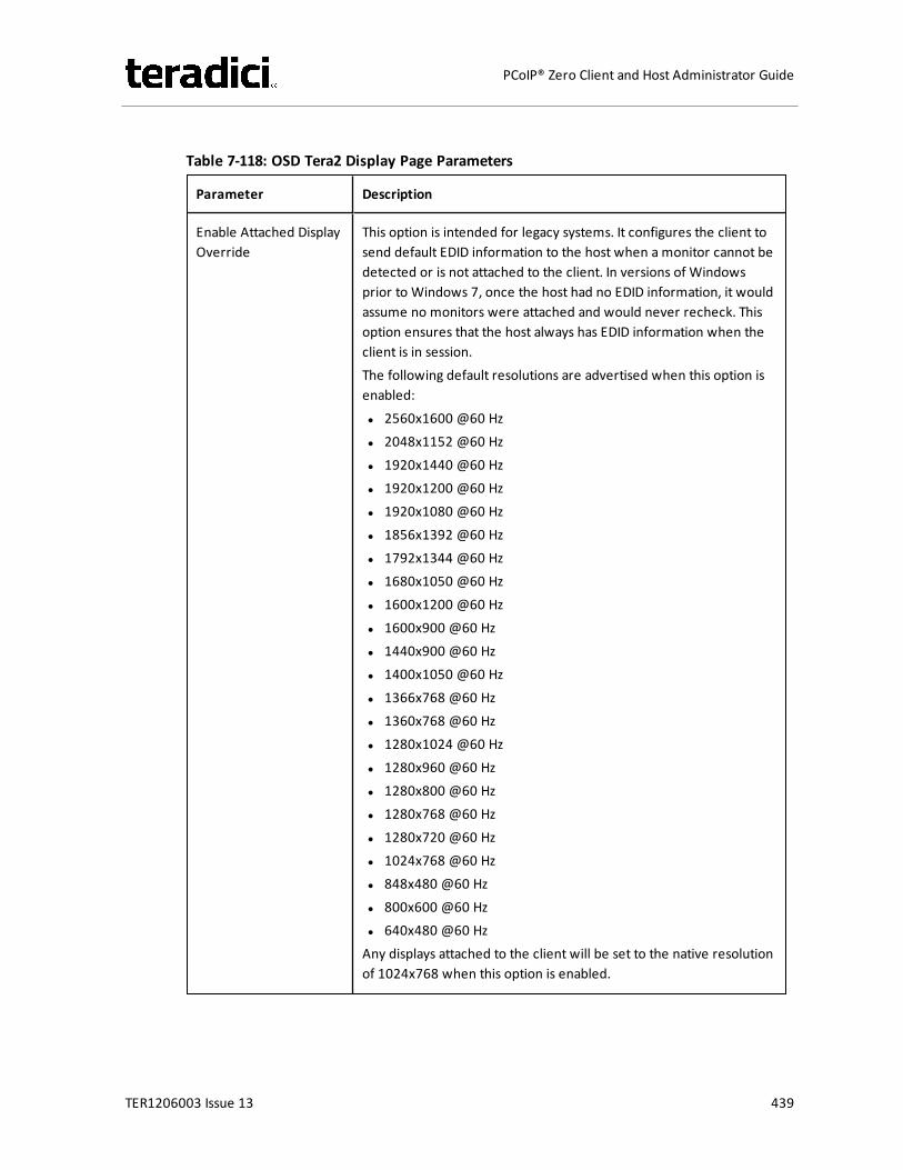
Table 7-118: OSD Tera2 Display Page Parameters
Parameter Description
Enable Attached DisplayOverride
This option is intended for legacy systems. It configures the client tosend default EDID information to the host when a monitor cannot bedetected or is not attached to the client. In versions of Windowsprior to Windows 7, once the host had no EDID information, it wouldassume no monitors were attached and would never recheck. Thisoption ensures that the host always has EDID information when theclient is in session.The following default resolutions are advertised when this option isenabled:l 2560x1600 @60 Hzl 2048x1152 @60 Hzl 1920x1440 @60 Hzl 1920x1200 @60 Hzl 1920x1080 @60 Hzl 1856x1392 @60 Hzl 1792x1344 @60 Hzl 1680x1050 @60 Hzl 1600x1200 @60 Hzl 1600x900 @60 Hzl 1440x900 @60 Hzl 1400x1050 @60 Hzl 1366x768 @60 Hzl 1360x768 @60 Hzl 1280x1024 @60 Hzl 1280x960 @60 Hzl 1280x800 @60 Hzl 1280x768 @60 Hzl 1280x720 @60 Hzl 1024x768 @60 Hzl 848x480 @60 Hzl 800x600 @60 Hzl 640x480 @60 HzAny displays attached to the client will be set to the native resolutionof 1024x768 when this option is enabled.
TER1206003 Issue 13 439
PCoIP® Zero Client and Host Administrator Guide
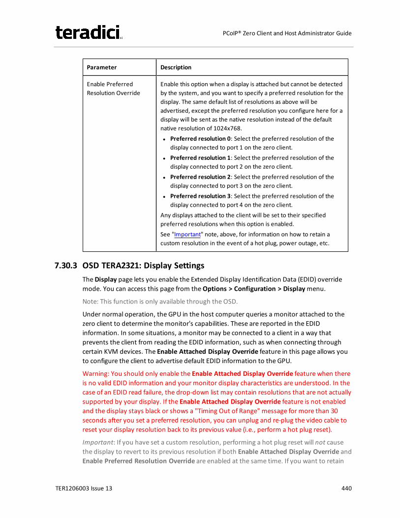
Parameter Description
Enable PreferredResolution Override
Enable this option when a display is attached but cannot be detectedby the system, and you want to specify a preferred resolution for thedisplay. The same default list of resolutions as above will beadvertised, except the preferred resolution you configure here for adisplay will be sent as the native resolution instead of the defaultnative resolution of 1024x768.l Preferred resolution 0: Select the preferred resolution of the
display connected to port 1 on the zero client.l Preferred resolution 1: Select the preferred resolution of the
display connected to port 2 on the zero client.l Preferred resolution 2: Select the preferred resolution of the
display connected to port 3 on the zero client.l Preferred resolution 3: Select the preferred resolution of the
display connected to port 4 on the zero client.Any displays attached to the client will be set to their specifiedpreferred resolutions when this option is enabled.See "Important" note, above, for information on how to retain acustom resolution in the event of a hot plug, power outage, etc.
7.30.3 OSD TERA2321: Display SettingsTheDisplay page lets you enable the Extended Display Identification Data (EDID) overridemode. You can access this page from theOptions > Configuration > Displaymenu.
Note: This function is only available through the OSD.
Under normal operation, the GPU in the host computer queries a monitor attached to thezero client to determine themonitor's capabilities. These are reported in the EDIDinformation. In some situations, a monitor may be connected to a client in a way thatprevents the client from reading the EDID information, such as when connecting throughcertain KVM devices. The Enable Attached Display Override feature in this page allows youto configure the client to advertise default EDID information to the GPU.
Warning: You should only enable the Enable Attached Display Override feature when thereis no valid EDID information and your monitor display characteristics are understood. In thecase of an EDID read failure, the drop-down list may contain resolutions that are not actuallysupported by your display. If the Enable Attached Display Override feature is not enabledand the display stays black or shows a "Timing Out of Range" message for more than 30seconds after you set a preferred resolution, you can unplug and re-plug the video cable toreset your display resolution back to its previous value (i.e., perform a hot plug reset).
Important: If you have set a custom resolution, performing a hot plug reset will not causethe display to revert to its previous resolution if both Enable Attached Display Override andEnable Preferred Resolution Override are enabled at the same time. If you want to retain
TER1206003 Issue 13 440
PCoIP® Zero Client and Host Administrator Guide
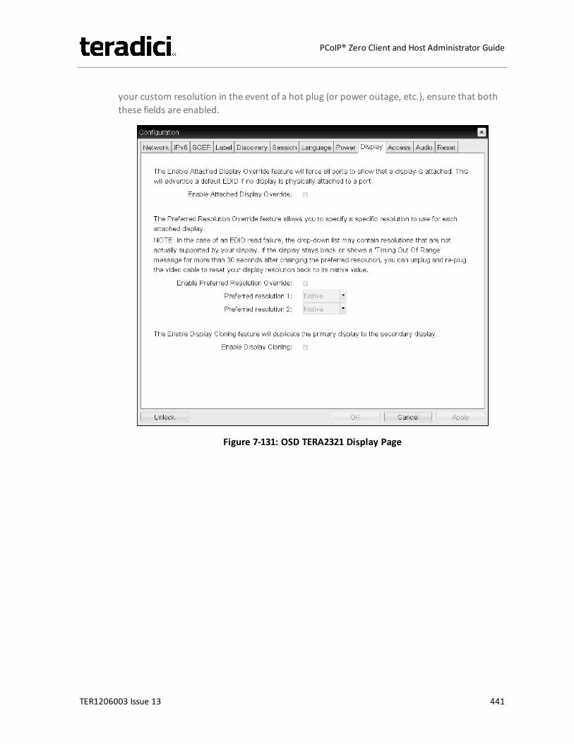
your custom resolution in the event of a hot plug (or power outage, etc.), ensure that boththese fields are enabled.
Figure 7-131: OSD TERA2321 Display Page
TER1206003 Issue 13 441
PCoIP® Zero Client and Host Administrator Guide
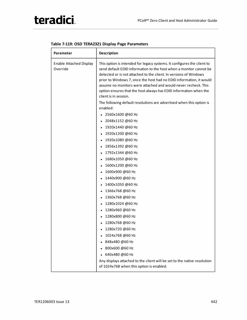
Table 7-119: OSD TERA2321 Display Page Parameters
Parameter Description
Enable Attached DisplayOverride
This option is intended for legacy systems. It configures the client tosend default EDID information to the host when a monitor cannot bedetected or is not attached to the client. In versions of Windowsprior to Windows 7, once the host had no EDID information, it wouldassume no monitors were attached and would never recheck. Thisoption ensures that the host always has EDID information when theclient is in session.The following default resolutions are advertised when this option isenabled:l 2560x1600 @60 Hzl 2048x1152 @60 Hzl 1920x1440 @60 Hzl 1920x1200 @60 Hzl 1920x1080 @60 Hzl 1856x1392 @60 Hzl 1792x1344 @60 Hzl 1680x1050 @60 Hzl 1600x1200 @60 Hzl 1600x900 @60 Hzl 1440x900 @60 Hzl 1400x1050 @60 Hzl 1366x768 @60 Hzl 1360x768 @60 Hzl 1280x1024 @60 Hzl 1280x960 @60 Hzl 1280x800 @60 Hzl 1280x768 @60 Hzl 1280x720 @60 Hzl 1024x768 @60 Hzl 848x480 @60 Hzl 800x600 @60 Hzl 640x480 @60 HzAny displays attached to the client will be set to the native resolutionof 1024x768 when this option is enabled.
TER1206003 Issue 13 442
PCoIP® Zero Client and Host Administrator Guide
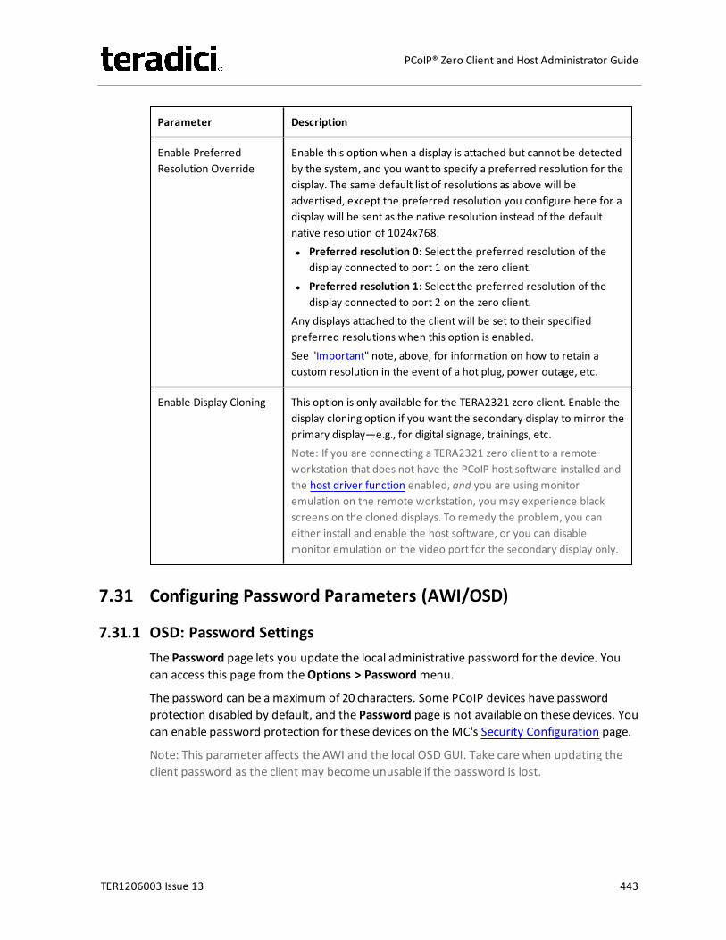
Parameter Description
Enable PreferredResolution Override
Enable this option when a display is attached but cannot be detectedby the system, and you want to specify a preferred resolution for thedisplay. The same default list of resolutions as above will beadvertised, except the preferred resolution you configure here for adisplay will be sent as the native resolution instead of the defaultnative resolution of 1024x768.l Preferred resolution 0: Select the preferred resolution of the
display connected to port 1 on the zero client.l Preferred resolution 1: Select the preferred resolution of the
display connected to port 2 on the zero client.Any displays attached to the client will be set to their specifiedpreferred resolutions when this option is enabled.See "Important" note, above, for information on how to retain acustom resolution in the event of a hot plug, power outage, etc.
Enable Display Cloning This option is only available for the TERA2321 zero client. Enable thedisplay cloning option if you want the secondary display to mirror theprimary display—e.g., for digital signage, trainings, etc.Note: If you are connecting a TERA2321 zero client to a remoteworkstation that does not have the PCoIP host software installed andthe host driver function enabled, and you are using monitoremulation on the remote workstation, you may experience blackscreens on the cloned displays. To remedy the problem, you caneither install and enable the host software, or you can disablemonitor emulation on the video port for the secondary display only.
7.31 Configuring Password Parameters (AWI/OSD)
7.31.1 OSD: Password SettingsThe Password page lets you update the local administrative password for the device. Youcan access this page from theOptions > Passwordmenu.
The password can be a maximum of 20 characters. Some PCoIP devices have passwordprotection disabled by default, and the Password page is not available on these devices. Youcan enable password protection for these devices on theMC's Security Configuration page.
Note: This parameter affects the AWI and the local OSD GUI. Take care when updating theclient password as the client may become unusable if the password is lost.
TER1206003 Issue 13 443
PCoIP® Zero Client and Host Administrator Guide
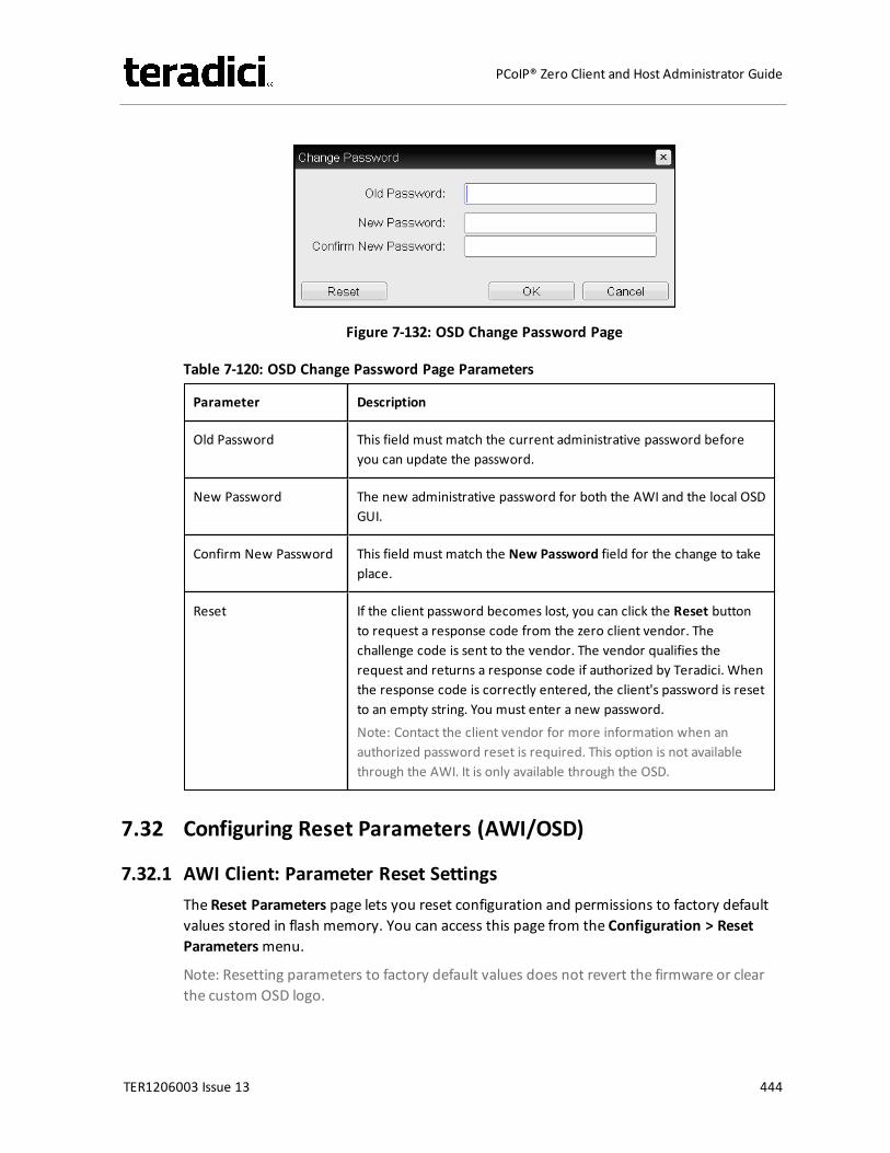
Figure 7-132: OSD Change Password Page
Table 7-120: OSD Change Password Page Parameters
Parameter Description
Old Password This field must match the current administrative password beforeyou can update the password.
New Password The new administrative password for both the AWI and the local OSDGUI.
Confirm New Password This field must match the New Password field for the change to takeplace.
Reset If the client password becomes lost, you can click the Reset buttonto request a response code from the zero client vendor. Thechallenge code is sent to the vendor. The vendor qualifies therequest and returns a response code if authorized by Teradici. Whenthe response code is correctly entered, the client's password is resetto an empty string. You must enter a new password.Note: Contact the client vendor for more information when anauthorized password reset is required. This option is not availablethrough the AWI. It is only available through the OSD.
7.32 Configuring Reset Parameters (AWI/OSD)
7.32.1 AWI Client: Parameter Reset SettingsThe Reset Parameters page lets you reset configuration and permissions to factory defaultvalues stored in flash memory. You can access this page from the Configuration > ResetParametersmenu.
Note: Resetting parameters to factory default values does not revert the firmware or clearthe custom OSD logo.
TER1206003 Issue 13 444
PCoIP® Zero Client and Host Administrator Guide
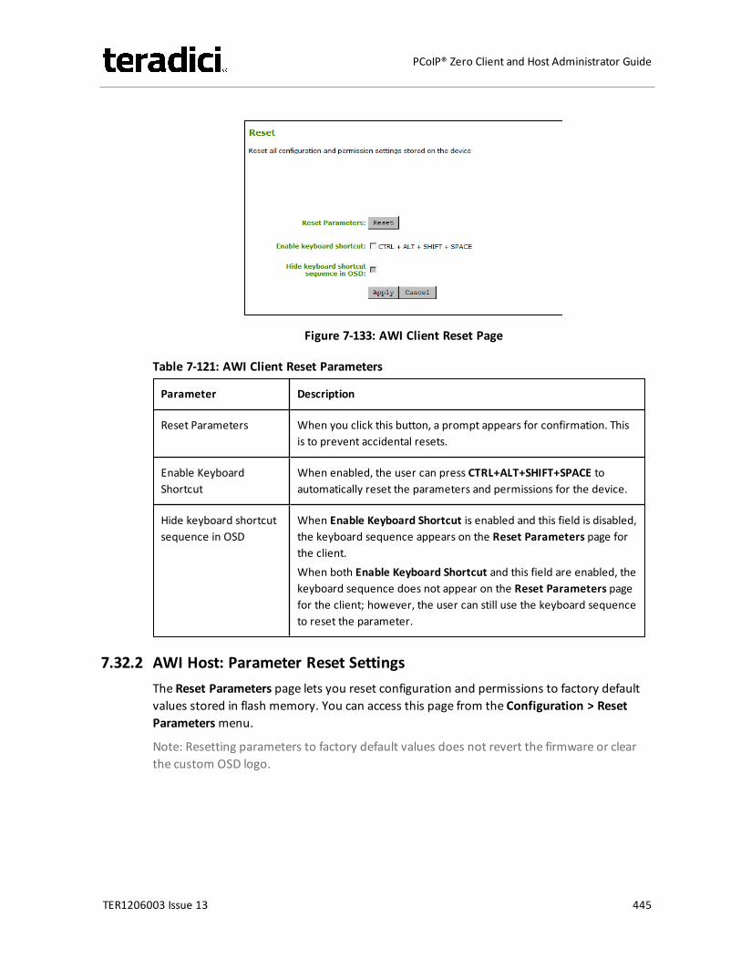
Figure 7-133: AWI Client Reset Page
Table 7-121: AWI Client Reset Parameters
Parameter Description
Reset Parameters When you click this button, a prompt appears for confirmation. Thisis to prevent accidental resets.
Enable KeyboardShortcut
When enabled, the user can press CTRL+ALT+SHIFT+SPACE toautomatically reset the parameters and permissions for the device.
Hide keyboard shortcutsequence in OSD
When Enable Keyboard Shortcut is enabled and this field is disabled,the keyboard sequence appears on the Reset Parameters page forthe client.When both Enable Keyboard Shortcut and this field are enabled, thekeyboard sequence does not appear on the Reset Parameters pagefor the client; however, the user can still use the keyboard sequenceto reset the parameter.
7.32.2 AWI Host: Parameter Reset SettingsThe Reset Parameters page lets you reset configuration and permissions to factory defaultvalues stored in flash memory. You can access this page from the Configuration > ResetParametersmenu.
Note: Resetting parameters to factory default values does not revert the firmware or clearthe custom OSD logo.
TER1206003 Issue 13 445
PCoIP® Zero Client and Host Administrator Guide
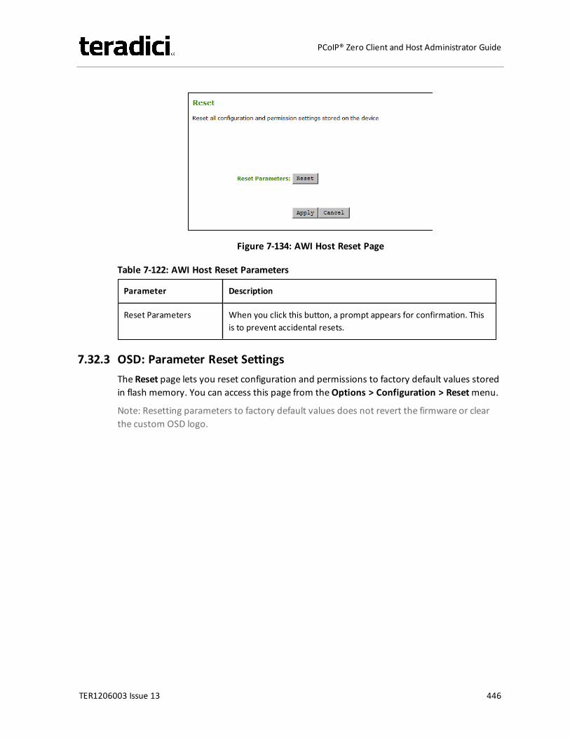
Figure 7-134: AWI Host Reset Page
Table 7-122: AWI Host Reset Parameters
Parameter Description
Reset Parameters When you click this button, a prompt appears for confirmation. Thisis to prevent accidental resets.
7.32.3 OSD: Parameter Reset SettingsThe Reset page lets you reset configuration and permissions to factory default values storedin flash memory. You can access this page from theOptions > Configuration > Resetmenu.
Note: Resetting parameters to factory default values does not revert the firmware or clearthe custom OSD logo.
TER1206003 Issue 13 446
PCoIP® Zero Client and Host Administrator Guide
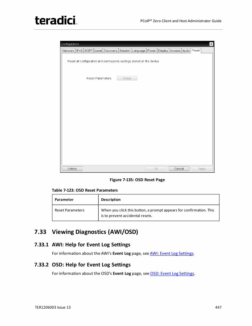
Figure 7-135: OSD Reset Page
Table 7-123: OSD Reset Parameters
Parameter Description
Reset Parameters When you click this button, a prompt appears for confirmation. Thisis to prevent accidental resets.
7.33 Viewing Diagnostics (AWI/OSD)
7.33.1 AWI: Help for Event Log SettingsFor information about the AWI's Event Log page, see AWI: Event Log Settings.
7.33.2 OSD: Help for Event Log SettingsFor information about the OSD's Event Log page, see OSD: Event Log Settings.
TER1206003 Issue 13 447
PCoIP® Zero Client and Host Administrator Guide
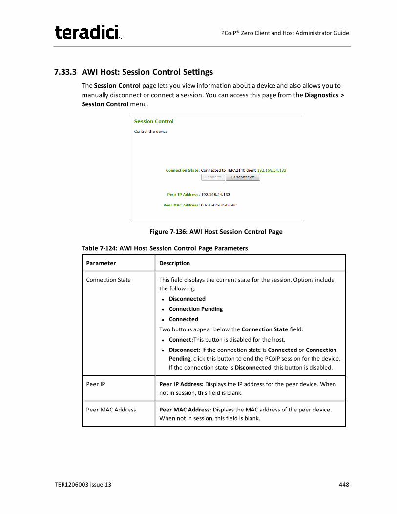
7.33.3 AWI Host: Session Control SettingsThe Session Control page lets you view information about a device and also allows you tomanually disconnect or connect a session. You can access this page from theDiagnostics >Session Controlmenu.
Figure 7-136: AWI Host Session Control Page
Table 7-124: AWI Host Session Control Page Parameters
Parameter Description
Connection State This field displays the current state for the session. Options includethe following:l Disconnectedl Connection Pendingl ConnectedTwo buttons appear below the Connection State field:l Connect:This button is disabled for the host.l Disconnect: If the connection state is Connected or Connection
Pending, click this button to end the PCoIP session for the device.If the connection state is Disconnected, this button is disabled.
Peer IP Peer IP Address: Displays the IP address for the peer device. Whennot in session, this field is blank.
Peer MAC Address Peer MAC Address: Displays the MAC address of the peer device.When not in session, this field is blank.
TER1206003 Issue 13 448
PCoIP® Zero Client and Host Administrator Guide
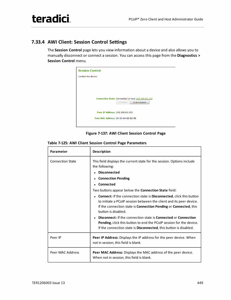
7.33.4 AWI Client: Session Control SettingsThe Session Control page lets you view information about a device and also allows you tomanually disconnect or connect a session. You can access this page from theDiagnostics >Session Controlmenu.
Figure 7-137: AWI Client Session Control Page
Table 7-125: AWI Client Session Control Page Parameters
Parameter Description
Connection State This field displays the current state for the session. Options includethe following:l Disconnectedl Connection Pendingl ConnectedTwo buttons appear below the Connection State field:l Connect: If the connection state is Disconnected, click this button
to initiate a PCoIP session between the client and its peer device.If the connection state is Connection Pending or Connected, thisbutton is disabled.
l Disconnect: If the connection state is Connected or ConnectionPending, click this button to end the PCoIP session for the device.If the connection state is Disconnected, this button is disabled.
Peer IP Peer IP Address: Displays the IP address for the peer device. Whennot in session, this field is blank.
Peer MAC Address Peer MAC Address: Displays the MAC address of the peer device.When not in session, this field is blank.
TER1206003 Issue 13 449
PCoIP® Zero Client and Host Administrator Guide
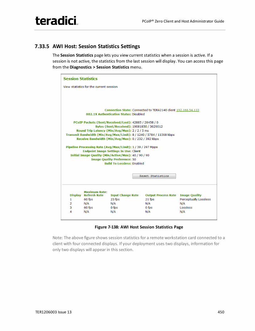
7.33.5 AWI Host: Session Statistics SettingsThe Session Statistics page lets you view current statistics when a session is active. If asession is not active, the statistics from the last session will display. You can access this pagefrom theDiagnostics > Session Statisticsmenu.
Figure 7-138: AWI Host Session Statistics Page
Note: The above figure shows session statistics for a remote workstation card connected to aclient with four connected displays. If your deployment uses two displays, information foronly two displays will appear in this section.
TER1206003 Issue 13 450
PCoIP® Zero Client and Host Administrator Guide
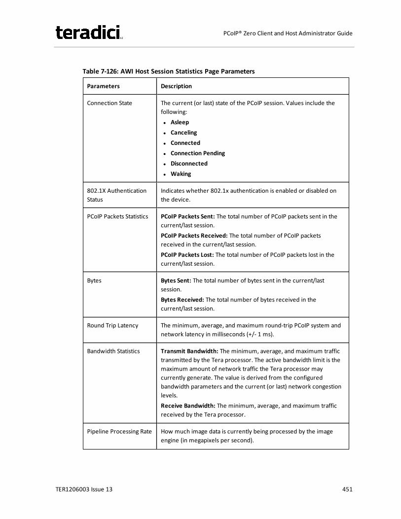
Table 7-126: AWI Host Session Statistics Page Parameters
Parameters Description
Connection State The current (or last) state of the PCoIP session. Values include thefollowing:l Asleepl Cancelingl Connectedl Connection Pendingl Disconnectedl Waking
802.1X AuthenticationStatus
Indicates whether 802.1x authentication is enabled or disabled onthe device.
PCoIP Packets Statistics PCoIP Packets Sent: The total number of PCoIP packets sent in thecurrent/last session.PCoIP Packets Received: The total number of PCoIP packetsreceived in the current/last session.PCoIP Packets Lost: The total number of PCoIP packets lost in thecurrent/last session.
Bytes Bytes Sent: The total number of bytes sent in the current/lastsession.Bytes Received: The total number of bytes received in thecurrent/last session.
Round Trip Latency The minimum, average, and maximum round-trip PCoIP system andnetwork latency in milliseconds (+/- 1 ms).
Bandwidth Statistics Transmit Bandwidth: The minimum, average, and maximum traffictransmitted by the Tera processor. The active bandwidth limit is themaximum amount of network traffic the Tera processor maycurrently generate. The value is derived from the configuredbandwidth parameters and the current (or last) network congestionlevels.Receive Bandwidth: The minimum, average, and maximum trafficreceived by the Tera processor.
Pipeline Processing Rate How much image data is currently being processed by the imageengine (in megapixels per second).
TER1206003 Issue 13 451
PCoIP® Zero Client and Host Administrator Guide

Parameters Description
Endpoint Image SettingsIn Use
Displays if the image settings being used are configured within theclient or within the host. This is based on how the Use Client ImageSettings field is configured on the Image page for the host device.
Initial Image Quality The minimum and maximum quality setting is taken from the Imagepage for the device.The active setting is what’s currently being used in the session andonly appears on the host.
Image QualityPreference
This setting is taken from the Image Quality Preference field on theImage page. The value determines if the image is set to a smootherversus a sharper image.
Build to Lossless Options that may appear in this field include the following:Enabled: The Disable Build to Lossless field on the Image page isunchecked.Disabled: The Disable Build to Lossless field is checked.
Reset Statistics Click this button to reset the statistic information on this page.Note: The Reset Statistics button also resets the statistics reportedin the Home page.
Display The port number for the display.
Maximum Rate This column shows the refresh rate of the attached display.If the Maximum Rate field on the Image page is set to 0 (i.e., there isno limit), the maximum rate is taken from the monitor's refresh rate.If the Maximum Rate field on the Image page is set to a valuegreater than 0, the refresh rate shows as "User Defined."
Input Change Rate The rate of content change from the GPU. This includes everythingthe user is doing (such as cursor movement, email editing, orstreaming video).
Output Process Rate The frame rate currently being sent from the image engine on thehost to the client.
Image Quality Shows the current lossless state of the attached display:l Lossyl Perceptually losslessl Lossless
TER1206003 Issue 13 452
PCoIP® Zero Client and Host Administrator Guide
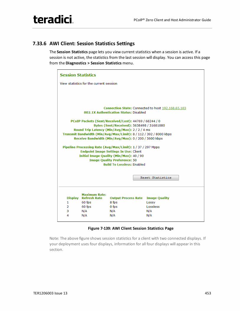
7.33.6 AWI Client: Session Statistics SettingsThe Session Statistics page lets you view current statistics when a session is active. If asession is not active, the statistics from the last session will display. You can access this pagefrom theDiagnostics > Session Statisticsmenu.
Figure 7-139: AWI Client Session Statistics Page
Note: The above figure shows session statistics for a client with two connected displays. Ifyour deployment uses four displays, information for all four displays will appear in thissection.
TER1206003 Issue 13 453
PCoIP® Zero Client and Host Administrator Guide
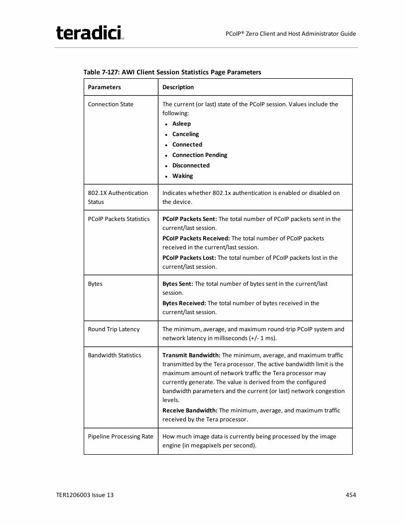
Table 7-127: AWI Client Session Statistics Page Parameters
Parameters Description
Connection State The current (or last) state of the PCoIP session. Values include thefollowing:l Asleepl Cancelingl Connectedl Connection Pendingl Disconnectedl Waking
802.1X AuthenticationStatus
Indicates whether 802.1x authentication is enabled or disabled onthe device.
PCoIP Packets Statistics PCoIP Packets Sent: The total number of PCoIP packets sent in thecurrent/last session.PCoIP Packets Received: The total number of PCoIP packetsreceived in the current/last session.PCoIP Packets Lost: The total number of PCoIP packets lost in thecurrent/last session.
Bytes Bytes Sent: The total number of bytes sent in the current/lastsession.Bytes Received: The total number of bytes received in thecurrent/last session.
Round Trip Latency The minimum, average, and maximum round-trip PCoIP system andnetwork latency in milliseconds (+/- 1 ms).
Bandwidth Statistics Transmit Bandwidth: The minimum, average, and maximum traffictransmitted by the Tera processor. The active bandwidth limit is themaximum amount of network traffic the Tera processor maycurrently generate. The value is derived from the configuredbandwidth parameters and the current (or last) network congestionlevels.Receive Bandwidth: The minimum, average, and maximum trafficreceived by the Tera processor.
Pipeline Processing Rate How much image data is currently being processed by the imageengine (in megapixels per second).
TER1206003 Issue 13 454
PCoIP® Zero Client and Host Administrator Guide
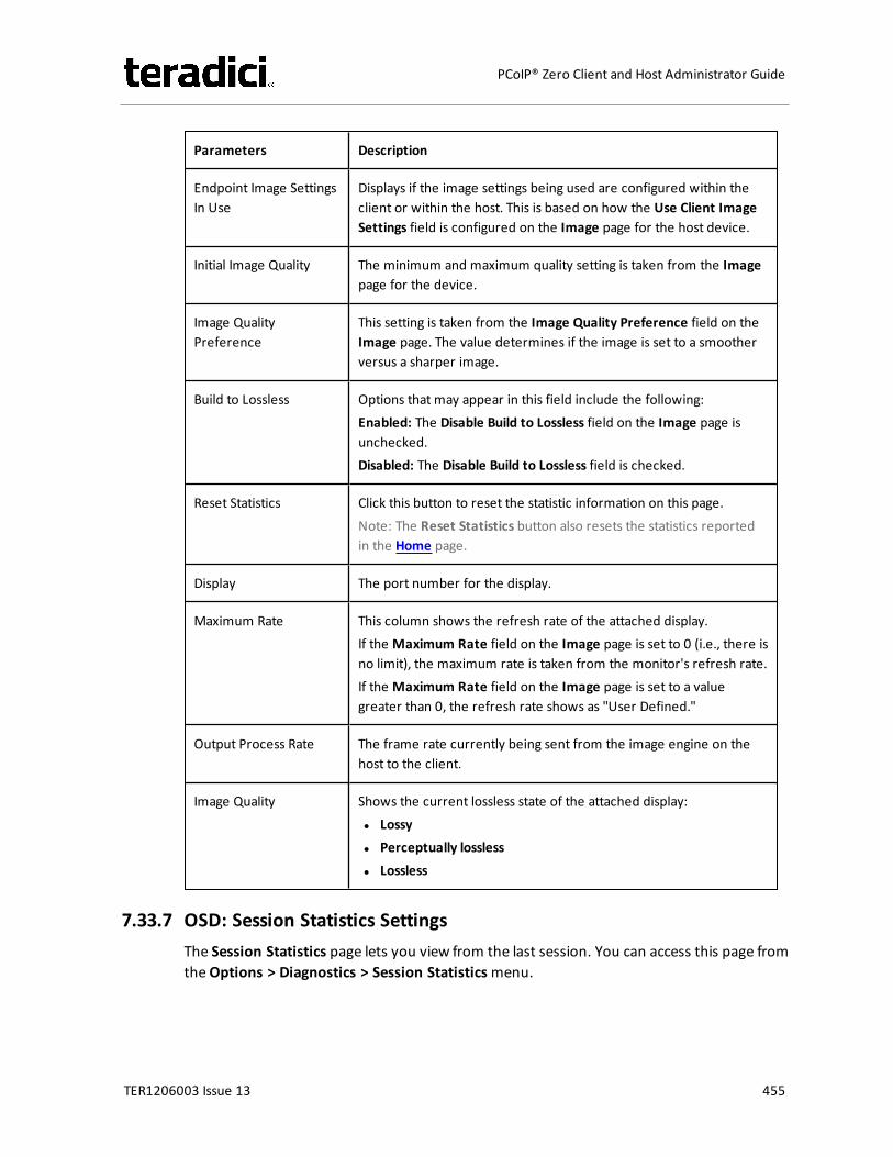
Parameters Description
Endpoint Image SettingsIn Use
Displays if the image settings being used are configured within theclient or within the host. This is based on how the Use Client ImageSettings field is configured on the Image page for the host device.
Initial Image Quality The minimum and maximum quality setting is taken from the Imagepage for the device.
Image QualityPreference
This setting is taken from the Image Quality Preference field on theImage page. The value determines if the image is set to a smootherversus a sharper image.
Build to Lossless Options that may appear in this field include the following:Enabled: The Disable Build to Lossless field on the Image page isunchecked.Disabled: The Disable Build to Lossless field is checked.
Reset Statistics Click this button to reset the statistic information on this page.Note: The Reset Statistics button also resets the statistics reportedin the Home page.
Display The port number for the display.
Maximum Rate This column shows the refresh rate of the attached display.If the Maximum Rate field on the Image page is set to 0 (i.e., there isno limit), the maximum rate is taken from the monitor's refresh rate.If the Maximum Rate field on the Image page is set to a valuegreater than 0, the refresh rate shows as "User Defined."
Output Process Rate The frame rate currently being sent from the image engine on thehost to the client.
Image Quality Shows the current lossless state of the attached display:l Lossyl Perceptually losslessl Lossless
7.33.7 OSD: Session Statistics SettingsThe Session Statistics page lets you view from the last session. You can access this page fromtheOptions > Diagnostics > Session Statisticsmenu.
TER1206003 Issue 13 455
PCoIP® Zero Client and Host Administrator Guide
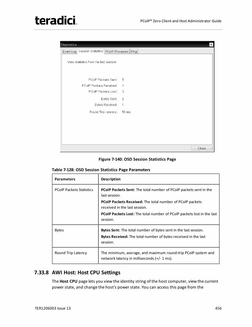
Figure 7-140: OSD Session Statistics Page
Table 7-128: OSD Session Statistics Page Parameters
Parameters Description
PCoIP Packets Statistics PCoIP Packets Sent: The total number of PCoIP packets sent in thelast session.PCoIP Packets Received: The total number of PCoIP packetsreceived in the last session.PCoIP Packets Lost: The total number of PCoIP packets lost in the lastsession.
Bytes Bytes Sent: The total number of bytes sent in the last session.Bytes Received: The total number of bytes received in the lastsession.
Round Trip Latency The minimum, average, and maximum round-trip PCoIP system andnetwork latency in milliseconds (+/- 1 ms).
7.33.8 AWI Host: Host CPU SettingsTheHost CPU page lets you view the identity string of the host computer, view the currentpower state, and change the host's power state. You can access this page from the
TER1206003 Issue 13 456
PCoIP® Zero Client and Host Administrator Guide
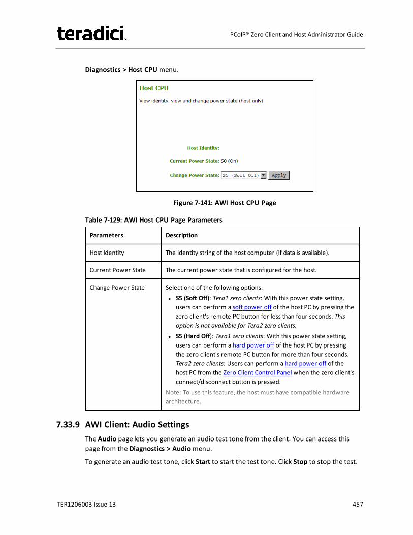
Diagnostics > Host CPUmenu.
Figure 7-141: AWI Host CPU Page
Table 7-129: AWI Host CPU Page Parameters
Parameters Description
Host Identity The identity string of the host computer (if data is available).
Current Power State The current power state that is configured for the host.
Change Power State Select one of the following options:l S5 (Soft Off): Tera1 zero clients: With this power state setting,
users can perform a soft power off of the host PC by pressing thezero client's remote PC button for less than four seconds. Thisoption is not available for Tera2 zero clients.
l S5 (Hard Off): Tera1 zero clients: With this power state setting,users can perform a hard power off of the host PC by pressingthe zero client's remote PC button for more than four seconds.Tera2 zero clients: Users can perform a hard power off of thehost PC from the Zero Client Control Panel when the zero client'sconnect/disconnect button is pressed.
Note: To use this feature, the host must have compatible hardwarearchitecture.
7.33.9 AWI Client: Audio SettingsThe Audio page lets you generate an audio test tone from the client. You can access thispage from theDiagnostics > Audiomenu.
To generate an audio test tone, click Start to start the test tone. Click Stop to stop the test.
TER1206003 Issue 13 457
PCoIP® Zero Client and Host Administrator Guide
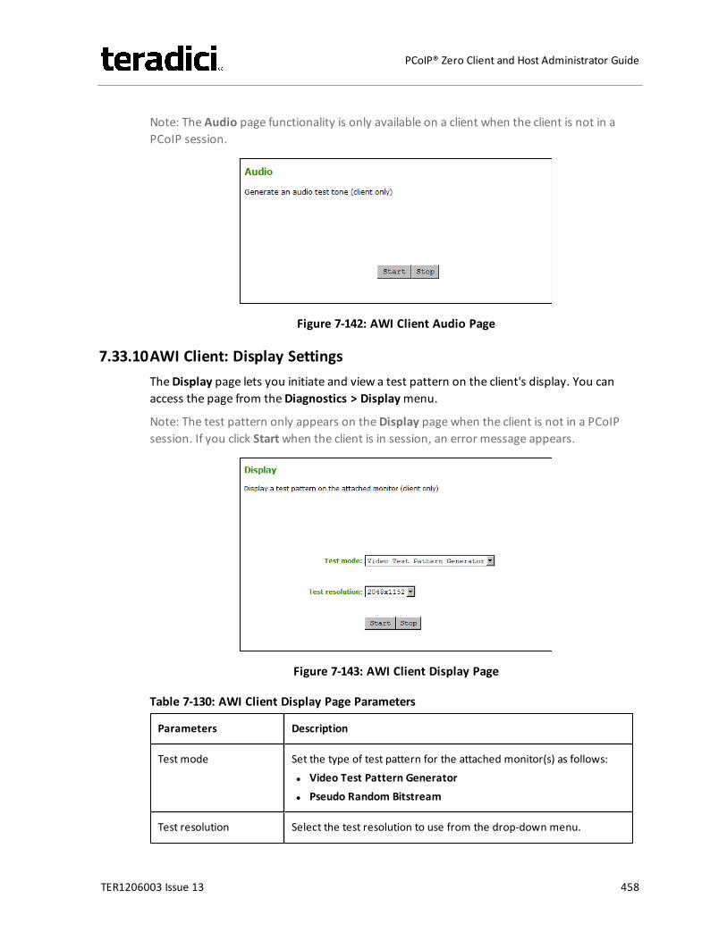
Note: The Audio page functionality is only available on a client when the client is not in aPCoIP session.
Figure 7-142: AWI Client Audio Page
7.33.10AWI Client: Display SettingsTheDisplay page lets you initiate and view a test pattern on the client's display. You canaccess the page from theDiagnostics > Displaymenu.
Note: The test pattern only appears on theDisplay page when the client is not in a PCoIPsession. If you click Startwhen the client is in session, an error message appears.
Figure 7-143: AWI Client Display Page
Table 7-130: AWI Client Display Page Parameters
Parameters Description
Test mode Set the type of test pattern for the attached monitor(s) as follows:l Video Test Pattern Generatorl Pseudo Random Bitstream
Test resolution Select the test resolution to use from the drop-down menu.
TER1206003 Issue 13 458
PCoIP® Zero Client and Host Administrator Guide
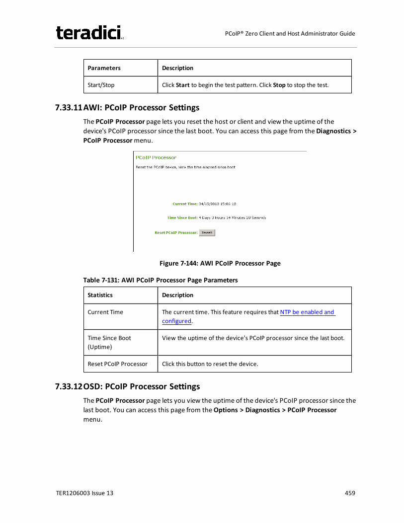
Parameters Description
Start/Stop Click Start to begin the test pattern. Click Stop to stop the test.
7.33.11AWI: PCoIP Processor SettingsThe PCoIP Processor page lets you reset the host or client and view the uptime of thedevice's PCoIP processor since the last boot. You can access this page from theDiagnostics >PCoIP Processormenu.
Figure 7-144: AWI PCoIP Processor Page
Table 7-131: AWI PCoIP Processor Page Parameters
Statistics Description
Current Time The current time. This feature requires that NTP be enabled andconfigured.
Time Since Boot(Uptime)
View the uptime of the device's PCoIP processor since the last boot.
Reset PCoIP Processor Click this button to reset the device.
7.33.12OSD: PCoIP Processor SettingsThe PCoIP Processor page lets you view the uptime of the device's PCoIP processor since thelast boot. You can access this page from theOptions > Diagnostics > PCoIP Processormenu.
TER1206003 Issue 13 459
PCoIP® Zero Client and Host Administrator Guide
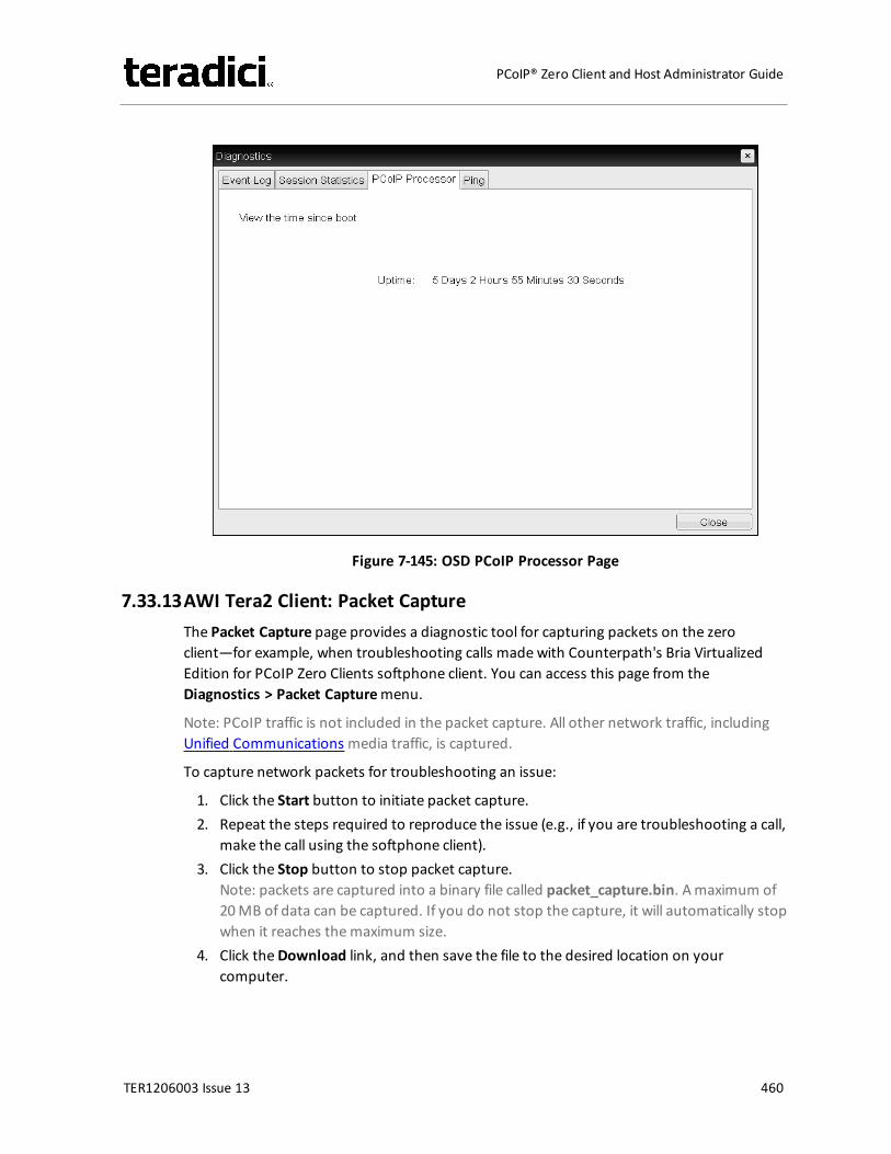
Figure 7-145: OSD PCoIP Processor Page
7.33.13AWI Tera2 Client: Packet CaptureThe Packet Capture page provides a diagnostic tool for capturing packets on the zeroclient—for example, when troubleshooting calls made with Counterpath's Bria VirtualizedEdition for PCoIP Zero Clients softphone client. You can access this page from theDiagnostics > Packet Capturemenu.
Note: PCoIP traffic is not included in the packet capture. All other network traffic, includingUnified Communications media traffic, is captured.
To capture network packets for troubleshooting an issue:
1. Click the Start button to initiate packet capture.2. Repeat the steps required to reproduce the issue (e.g., if you are troubleshooting a call,
make the call using the softphone client).3. Click the Stop button to stop packet capture.
Note: packets are captured into a binary file called packet_capture.bin. Amaximum of20MB of data can be captured. If you do not stop the capture, it will automatically stopwhen it reaches themaximum size.
4. Click theDownload link, and then save the file to the desired location on yourcomputer.
TER1206003 Issue 13 460
PCoIP® Zero Client and Host Administrator Guide
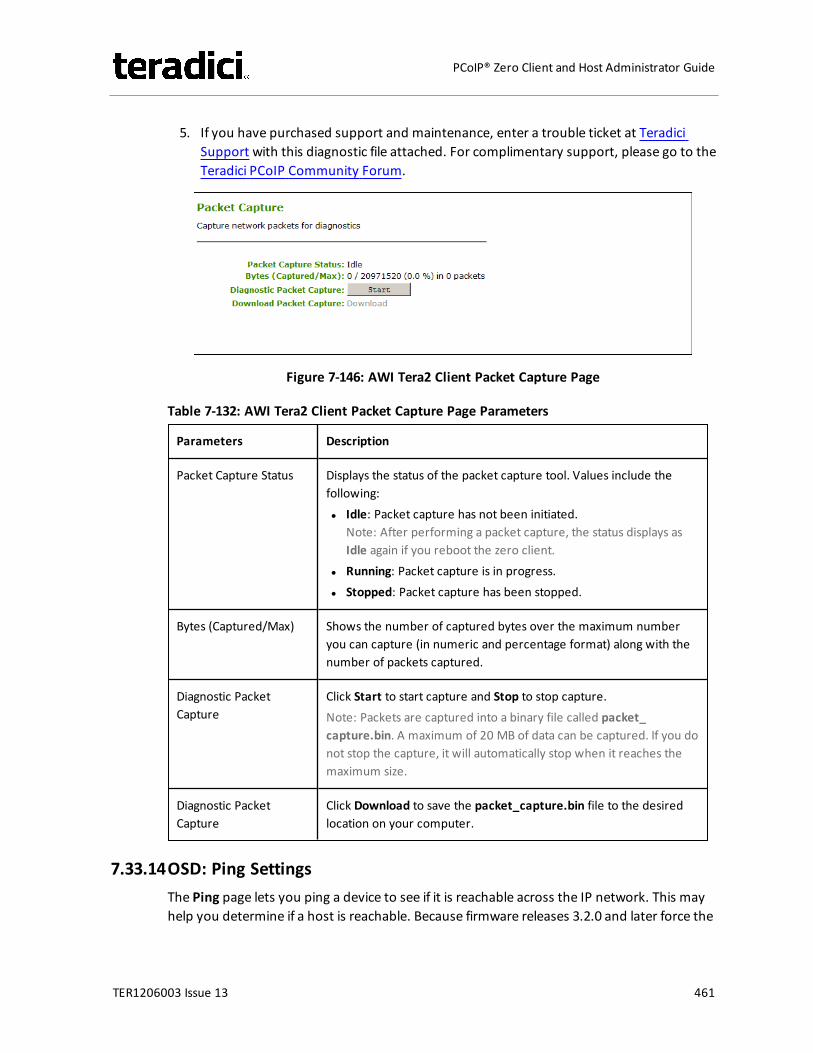
5. If you have purchased support and maintenance, enter a trouble ticket at TeradiciSupport with this diagnostic file attached. For complimentary support, please go to theTeradici PCoIP Community Forum.
Figure 7-146: AWI Tera2 Client Packet Capture Page
Table 7-132: AWI Tera2 Client Packet Capture Page Parameters
Parameters Description
Packet Capture Status Displays the status of the packet capture tool. Values include thefollowing:l Idle: Packet capture has not been initiated.
Note: After performing a packet capture, the status displays asIdle again if you reboot the zero client.
l Running: Packet capture is in progress.l Stopped: Packet capture has been stopped.
Bytes (Captured/Max) Shows the number of captured bytes over the maximum numberyou can capture (in numeric and percentage format) along with thenumber of packets captured.
Diagnostic PacketCapture
Click Start to start capture and Stop to stop capture.Note: Packets are captured into a binary file called packet_capture.bin. A maximum of 20 MB of data can be captured. If you donot stop the capture, it will automatically stop when it reaches themaximum size.
Diagnostic PacketCapture
Click Download to save the packet_capture.bin file to the desiredlocation on your computer.
7.33.14OSD: Ping SettingsThe Ping page lets you ping a device to see if it is reachable across the IP network. This mayhelp you determine if a host is reachable. Because firmware releases 3.2.0 and later force the
TER1206003 Issue 13 461
PCoIP® Zero Client and Host Administrator Guide
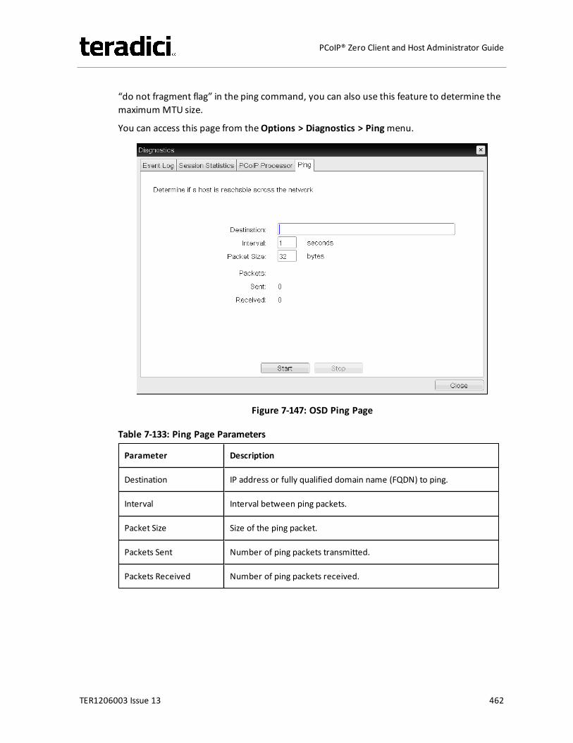
“do not fragment flag” in the ping command, you can also use this feature to determine themaximumMTU size.
You can access this page from theOptions > Diagnostics > Pingmenu.
Figure 7-147: OSD Ping Page
Table 7-133: Ping Page Parameters
Parameter Description
Destination IP address or fully qualified domain name (FQDN) to ping.
Interval Interval between ping packets.
Packet Size Size of the ping packet.
Packets Sent Number of ping packets transmitted.
Packets Received Number of ping packets received.
TER1206003 Issue 13 462
PCoIP® Zero Client and Host Administrator Guide
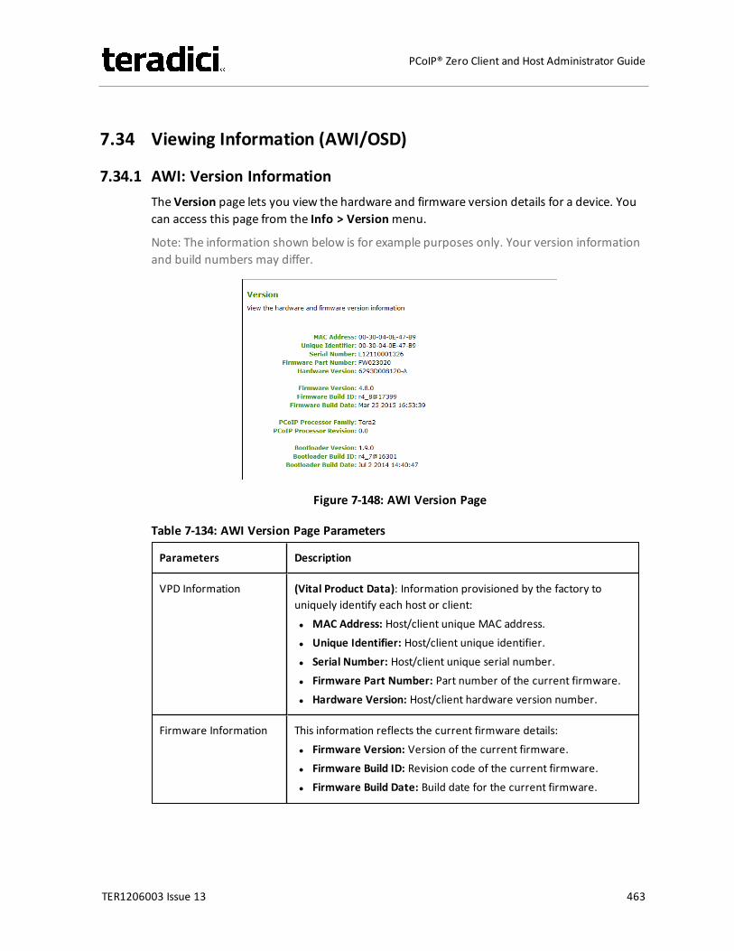
7.34 Viewing Information (AWI/OSD)
7.34.1 AWI: Version InformationThe Version page lets you view the hardware and firmware version details for a device. Youcan access this page from the Info > Versionmenu.
Note: The information shown below is for example purposes only. Your version informationand build numbers may differ.
Figure 7-148: AWI Version Page
Table 7-134: AWI Version Page Parameters
Parameters Description
VPD Information (Vital Product Data): Information provisioned by the factory touniquely identify each host or client:l MAC Address: Host/client unique MAC address.l Unique Identifier: Host/client unique identifier.l Serial Number: Host/client unique serial number.l Firmware Part Number: Part number of the current firmware.l Hardware Version: Host/client hardware version number.
Firmware Information This information reflects the current firmware details:l Firmware Version: Version of the current firmware.l Firmware Build ID: Revision code of the current firmware.l Firmware Build Date: Build date for the current firmware.
TER1206003 Issue 13 463
PCoIP® Zero Client and Host Administrator Guide
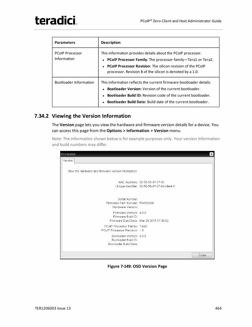
Parameters Description
PCoIP ProcessorInformation
This information provides details about the PCoIP processor.l PCoIP Processor Family: The processor family—Tera1 or Tera2.l PCoIP Processor Revision: The silicon revision of the PCoIP
processor. Revision B of the silicon is denoted by a 1.0.
Bootloader Information This information reflects the current firmware bootloader details:l Boatloader Version: Version of the current bootloader.l Bootloader Build ID: Revision code of the current bootloader.l Bootloader Build Date: Build date of the current bootloader.
7.34.2 Viewing the Version InformationThe Version page lets you view the hardware and firmware version details for a device. Youcan access this page from theOptions > Information > Versionmenu.
Note: The information shown below is for example purposes only. Your version informationand build numbers may differ.
Figure 7-149: OSD Version Page
TER1206003 Issue 13 464
PCoIP® Zero Client and Host Administrator Guide
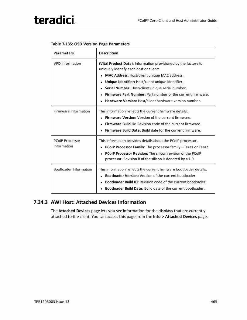
Table 7-135: OSD Version Page Parameters
Parameters Description
VPD Information (Vital Product Data): Information provisioned by the factory touniquely identify each host or client:l MAC Address: Host/client unique MAC address.l Unique Identifier: Host/client unique identifier.l Serial Number: Host/client unique serial number.l Firmware Part Number: Part number of the current firmware.l Hardware Version: Host/client hardware version number.
Firmware Information This information reflects the current firmware details:l Firmware Version: Version of the current firmware.l Firmware Build ID: Revision code of the current firmware.l Firmware Build Date: Build date for the current firmware.
PCoIP ProcessorInformation
This information provides details about the PCoIP processor.l PCoIP Processor Family: The processor family—Tera1 or Tera2.l PCoIP Processor Revision: The silicon revision of the PCoIP
processor. Revision B of the silicon is denoted by a 1.0.
Bootloader Information This information reflects the current firmware bootloader details:l Boatloader Version: Version of the current bootloader.l Bootloader Build ID: Revision code of the current bootloader.l Bootloader Build Date: Build date of the current bootloader.
7.34.3 AWI Host: Attached Devices InformationThe Attached Devices page lets you see information for the displays that are currentlyattached to the client. You can access this page from the Info > Attached Devices page.
TER1206003 Issue 13 465
PCoIP® Zero Client and Host Administrator Guide
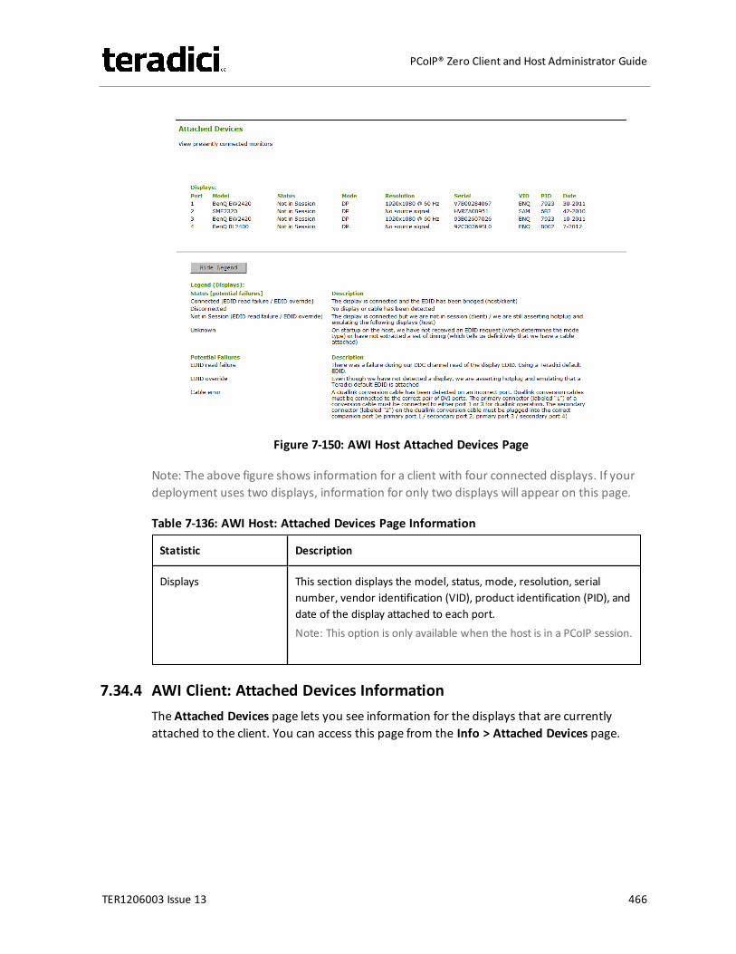
Figure 7-150: AWI Host Attached Devices Page
Note: The above figure shows information for a client with four connected displays. If yourdeployment uses two displays, information for only two displays will appear on this page.
Table 7-136: AWI Host: Attached Devices Page Information
Statistic Description
Displays This section displays the model, status, mode, resolution, serialnumber, vendor identification (VID), product identification (PID), anddate of the display attached to each port.Note: This option is only available when the host is in a PCoIP session.
7.34.4 AWI Client: Attached Devices InformationThe Attached Devices page lets you see information for the displays that are currentlyattached to the client. You can access this page from the Info > Attached Devices page.
TER1206003 Issue 13 466
PCoIP® Zero Client and Host Administrator Guide
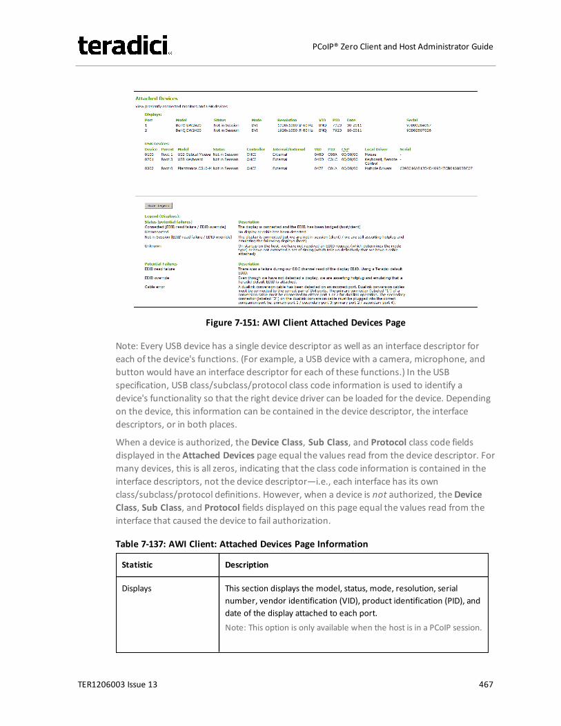
Figure 7-151: AWI Client Attached Devices Page
Note: Every USB device has a single device descriptor as well as an interface descriptor foreach of the device's functions. (For example, a USB device with a camera, microphone, andbutton would have an interface descriptor for each of these functions.) In the USBspecification, USB class/subclass/protocol class code information is used to identify adevice's functionality so that the right device driver can be loaded for the device. Dependingon the device, this information can be contained in the device descriptor, the interfacedescriptors, or in both places.
When a device is authorized, theDevice Class, Sub Class, and Protocol class code fieldsdisplayed in the Attached Devices page equal the values read from the device descriptor. Formany devices, this is all zeros, indicating that the class code information is contained in theinterface descriptors, not the device descriptor—i.e., each interface has its ownclass/subclass/protocol definitions. However, when a device is not authorized, theDeviceClass, Sub Class, and Protocol fields displayed on this page equal the values read from theinterface that caused the device to fail authorization.
Table 7-137: AWI Client: Attached Devices Page Information
Statistic Description
Displays This section displays the model, status, mode, resolution, serialnumber, vendor identification (VID), product identification (PID), anddate of the display attached to each port.Note: This option is only available when the host is in a PCoIP session.
TER1206003 Issue 13 467
PCoIP® Zero Client and Host Administrator Guide
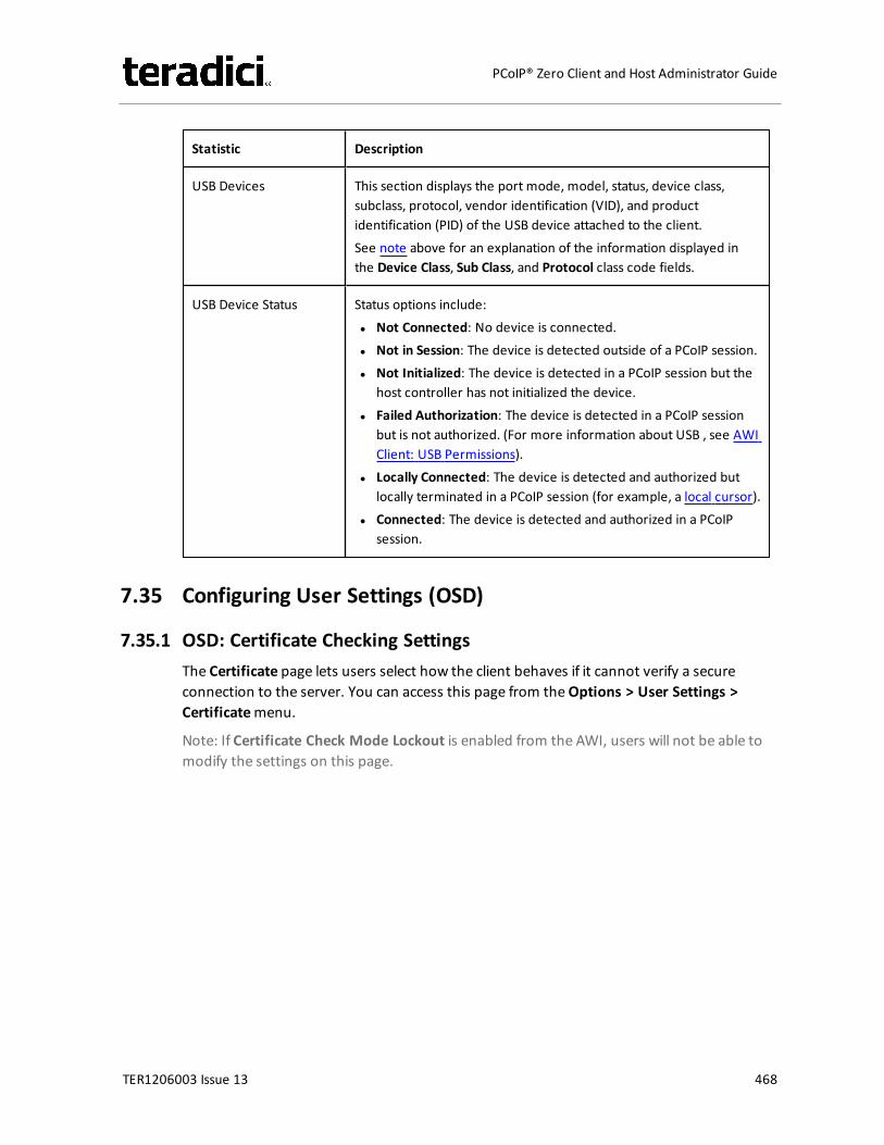
Statistic Description
USB Devices This section displays the port mode, model, status, device class,subclass, protocol, vendor identification (VID), and productidentification (PID) of the USB device attached to the client.See note above for an explanation of the information displayed inthe Device Class, Sub Class, and Protocol class code fields.
USB Device Status Status options include:l Not Connected: No device is connected.l Not in Session: The device is detected outside of a PCoIP session.l Not Initialized: The device is detected in a PCoIP session but the
host controller has not initialized the device.l Failed Authorization: The device is detected in a PCoIP session
but is not authorized. (For more information about USB , see AWIClient: USB Permissions).
l Locally Connected: The device is detected and authorized butlocally terminated in a PCoIP session (for example, a local cursor).
l Connected: The device is detected and authorized in a PCoIPsession.
7.35 Configuring User Settings (OSD)
7.35.1 OSD: Certificate Checking SettingsThe Certificate page lets users select how the client behaves if it cannot verify a secureconnection to the server. You can access this page from theOptions > User Settings >Certificatemenu.
Note: If Certificate Check Mode Lockout is enabled from the AWI, users will not be able tomodify the settings on this page.
TER1206003 Issue 13 468
PCoIP® Zero Client and Host Administrator Guide
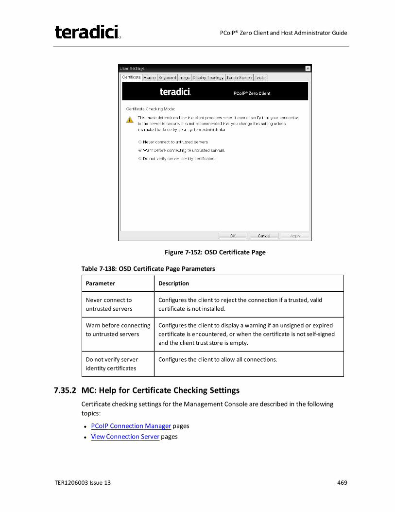
Figure 7-152: OSD Certificate Page
Table 7-138: OSD Certificate Page Parameters
Parameter Description
Never connect tountrusted servers
Configures the client to reject the connection if a trusted, validcertificate is not installed.
Warn before connectingto untrusted servers
Configures the client to display a warning if an unsigned or expiredcertificate is encountered, or when the certificate is not self-signedand the client trust store is empty.
Do not verify serveridentity certificates
Configures the client to allow all connections.
7.35.2 MC: Help for Certificate Checking SettingsCertificate checking settings for theManagement Console are described in the followingtopics:
l PCoIP Connection Manager pagesl View Connection Server pages
TER1206003 Issue 13 469
PCoIP® Zero Client and Host Administrator Guide
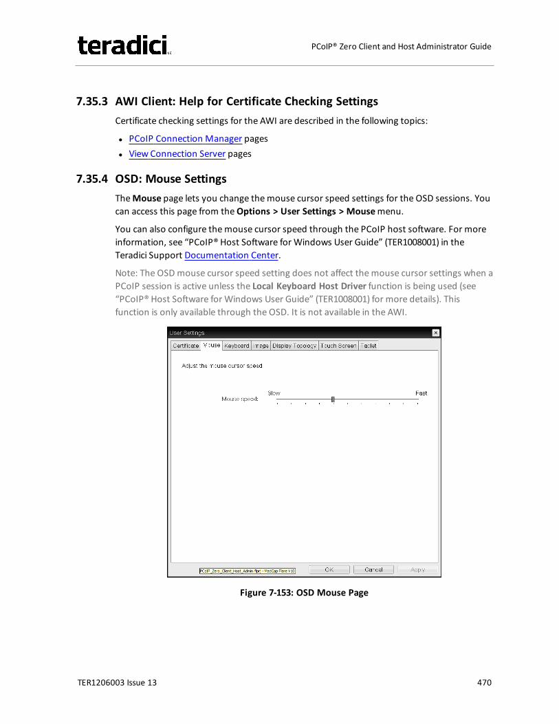
7.35.3 AWI Client: Help for Certificate Checking SettingsCertificate checking settings for the AWI are described in the following topics:
l PCoIP Connection Manager pagesl View Connection Server pages
7.35.4 OSD: Mouse SettingsTheMouse page lets you change themouse cursor speed settings for the OSD sessions. Youcan access this page from theOptions > User Settings > Mousemenu.
You can also configure themouse cursor speed through the PCoIP host software. For moreinformation, see “PCoIP® Host Software for Windows User Guide” (TER1008001) in theTeradici Support Documentation Center.
Note: The OSDmouse cursor speed setting does not affect themouse cursor settings when aPCoIP session is active unless the Local Keyboard Host Driver function is being used (see“PCoIP® Host Software for Windows User Guide” (TER1008001) for more details). Thisfunction is only available through the OSD. It is not available in the AWI.
Figure 7-153: OSD Mouse Page
TER1206003 Issue 13 470
PCoIP® Zero Client and Host Administrator Guide
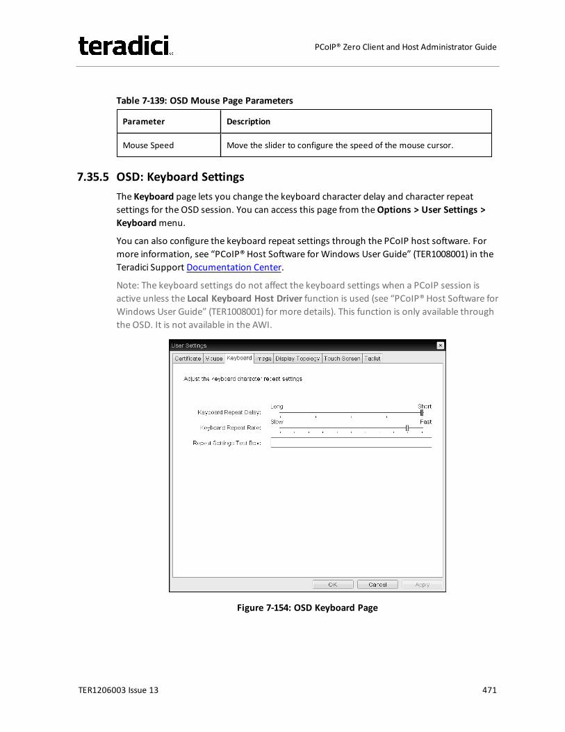
Table 7-139: OSD Mouse Page Parameters
Parameter Description
Mouse Speed Move the slider to configure the speed of the mouse cursor.
7.35.5 OSD: Keyboard SettingsThe Keyboard page lets you change the keyboard character delay and character repeatsettings for the OSD session. You can access this page from theOptions > User Settings >Keyboardmenu.
You can also configure the keyboard repeat settings through the PCoIP host software. Formore information, see “PCoIP® Host Software for Windows User Guide” (TER1008001) in theTeradici Support Documentation Center.
Note: The keyboard settings do not affect the keyboard settings when a PCoIP session isactive unless the Local Keyboard Host Driver function is used (see “PCoIP® Host Software forWindows User Guide” (TER1008001) for more details). This function is only available throughthe OSD. It is not available in the AWI.
Figure 7-154: OSD Keyboard Page
TER1206003 Issue 13 471
PCoIP® Zero Client and Host Administrator Guide
Table 7-140: OSD Keyboard Page Parameters
Parameter Description
Keyboard Repeat Delay Move the slider to configure the time that elapses before a characterbegins to repeat when it is held down.
Keyboard Repeat Rate Move the slider to configure the speed at which a character repeatswhen it is held down.
Repeat Settings Test Box Type in this box to test the chosen keyboard settings.
7.35.6 OSD: Help for Image SettingsFor information about the OSD's Image page, see OSD: Image Settings.
7.35.7 OSD: Help for Display Topology SettingsFor information about the OSD's Topology page, see OSD: Dual-display Topology Settings orOSD: Quad-display Topology Settings.
7.35.8 OSD: Touch Screen SettingsThe Touch Screen page lets you configure and calibrate settings for an attached EloTouchSystems touch screen display. See Setting up a Touch Screen Display for moreinformation about installing and configuring this device.
Note: Elo IntelliTouch and Elo AccuTouch are the only Elo TouchSystems touch screenssupported.
You can access this page from theOptions > User Settings > Touch Screenmenu.
Note: The Touch Screen page is only available through the OSD. It is not available from theAWI.
TER1206003 Issue 13 472
PCoIP® Zero Client and Host Administrator Guide
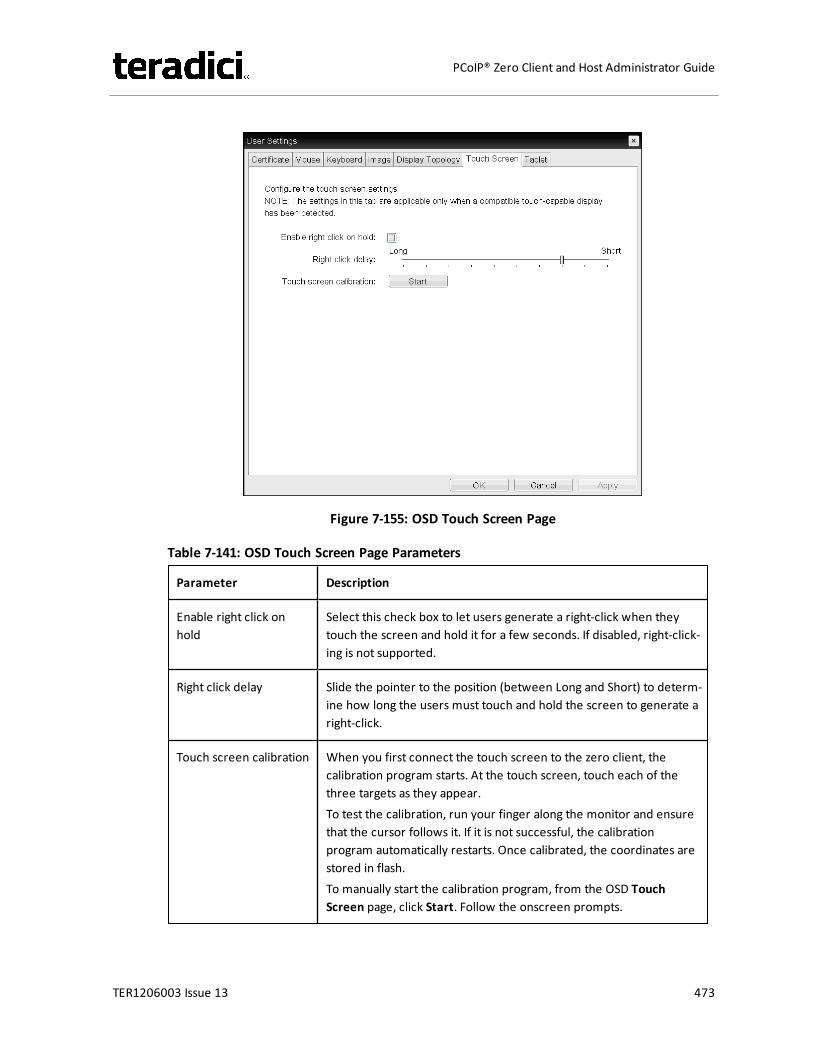
Figure 7-155: OSD Touch Screen Page
Table 7-141: OSD Touch Screen Page Parameters
Parameter Description
Enable right click onhold
Select this check box to let users generate a right-click when theytouch the screen and hold it for a few seconds. If disabled, right-click-ing is not supported.
Right click delay Slide the pointer to the position (between Long and Short) to determ-ine how long the users must touch and hold the screen to generate aright-click.
Touch screen calibration When you first connect the touch screen to the zero client, thecalibration program starts. At the touch screen, touch each of thethree targets as they appear.To test the calibration, run your finger along the monitor and ensurethat the cursor follows it. If it is not successful, the calibrationprogram automatically restarts. Once calibrated, the coordinates arestored in flash.To manually start the calibration program, from the OSD TouchScreen page, click Start. Follow the onscreen prompts.
TER1206003 Issue 13 473
PCoIP® Zero Client and Host Administrator Guide
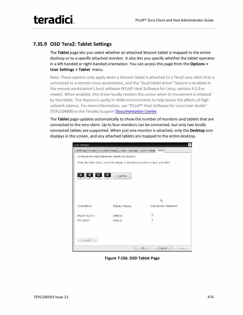
7.35.9 OSD Tera2: Tablet SettingsThe Tablet page lets you select whether an attached Wacom tablet is mapped to the entiredesktop or to a specific attached monitor. It also lets you specify whether the tablet operatesin a left-handed or right-handed orientation. You can access this page from theOptions >User Settings > Tablet menu.
Note: These options only apply when aWacom tablet is attached to a Tera2 zero client that isconnected to a remote Linux workstation, and the "local tablet driver" feature is enabled inthe remote workstation's host software (PCoIP Host Software for Linux, version 4.5.0 ornewer). When enabled, this driver locally renders the cursor when its movement is initiatedby the tablet. This feature is useful in WAN environments to help lessen the effects of highnetwork latency. For more information, see “PCoIP® Host Software for Linux User Guide”(TER1104006) in the Teradici Support Documentation Center.
The Tablet page updates automatically to show the number ofmonitors and tablets that areconnected to the zero client. Up to four monitors can be connected, but only two locallyconnected tablets are supported. When just onemonitor is attached, only theDesktop icondisplays in the screen, and any attached tablets aremapped to the entire desktop.
Figure 7-156: OSD Tablet Page
TER1206003 Issue 13 474
PCoIP® Zero Client and Host Administrator Guide
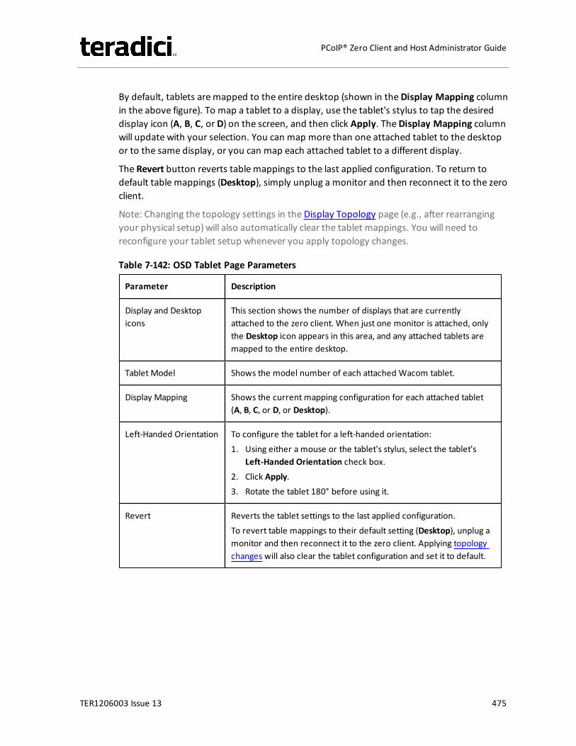
By default, tablets aremapped to the entire desktop (shown in theDisplay Mapping columnin the above figure). To map a tablet to a display, use the tablet's stylus to tap the desireddisplay icon (A, B, C, or D) on the screen, and then click Apply. TheDisplay Mapping columnwill update with your selection. You can map more than one attached tablet to the desktopor to the same display, or you can map each attached tablet to a different display.
The Revert button reverts table mappings to the last applied configuration. To return todefault table mappings (Desktop), simply unplug a monitor and then reconnect it to the zeroclient.
Note: Changing the topology settings in the Display Topology page (e.g., after rearrangingyour physical setup) will also automatically clear the tablet mappings. You will need toreconfigure your tablet setup whenever you apply topology changes.
Table 7-142: OSD Tablet Page Parameters
Parameter Description
Display and Desktopicons
This section shows the number of displays that are currentlyattached to the zero client. When just one monitor is attached, onlythe Desktop icon appears in this area, and any attached tablets aremapped to the entire desktop.
Tablet Model Shows the model number of each attached Wacom tablet.
Display Mapping Shows the current mapping configuration for each attached tablet(A, B, C, or D, or Desktop).
Left-Handed Orientation To configure the tablet for a left-handed orientation:1. Using either a mouse or the tablet's stylus, select the tablet's
Left-Handed Orientation check box.2. Click Apply.3. Rotate the tablet 180° before using it.
Revert Reverts the tablet settings to the last applied configuration.To revert table mappings to their default setting (Desktop), unplug amonitor and then reconnect it to the zero client. Applying topologychanges will also clear the tablet configuration and set it to default.
TER1206003 Issue 13 475
PCoIP® Zero Client and Host Administrator Guide
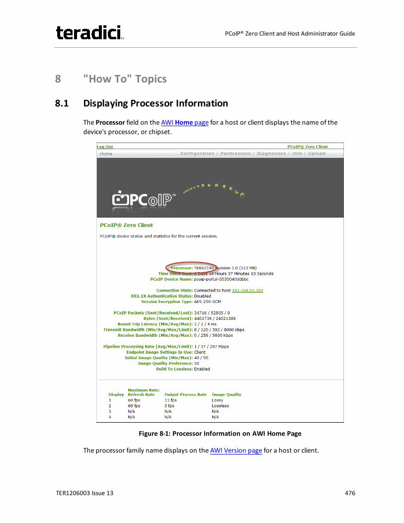
8 "How To" Topics
8.1 Displaying Processor Information
The Processor field on the AWI Home page for a host or client displays the name of thedevice's processor, or chipset.
Figure 8-1: Processor Information on AWI Home Page
The processor family name displays on the AWI Version page for a host or client.
TER1206003 Issue 13 476
PCoIP® Zero Client and Host Administrator Guide
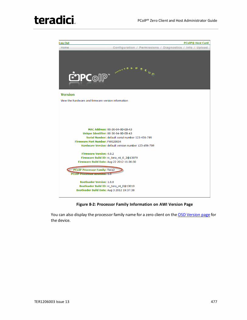
Figure 8-2: Processor Family Information on AWI Version Page
You can also display the processor family name for a zero client on the OSD Version page forthe device.
TER1206003 Issue 13 477
PCoIP® Zero Client and Host Administrator Guide
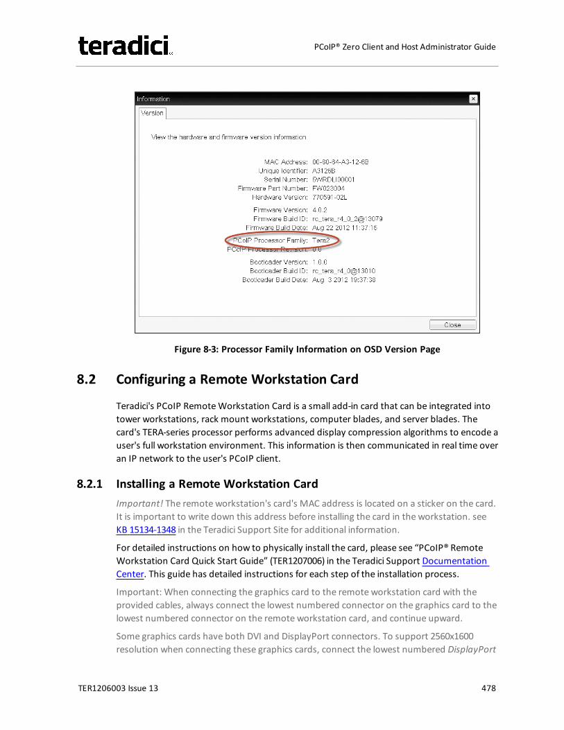
Figure 8-3: Processor Family Information on OSD Version Page
8.2 Configuring a Remote Workstation Card
Teradici's PCoIP RemoteWorkstation Card is a small add-in card that can be integrated intotower workstations, rack mount workstations, computer blades, and server blades. Thecard's TERA-series processor performs advanced display compression algorithms to encode auser's full workstation environment. This information is then communicated in real time overan IP network to the user's PCoIP client.
8.2.1 Installing a Remote Workstation CardImportant! The remote workstation's card's MAC address is located on a sticker on the card.It is important to write down this address before installing the card in the workstation. seeKB 15134-1348 in the Teradici Support Site for additional information.
For detailed instructions on how to physically install the card, please see “PCoIP® RemoteWorkstation Card Quick Start Guide” (TER1207006) in the Teradici Support DocumentationCenter. This guide has detailed instructions for each step of the installation process.
Important: When connecting the graphics card to the remote workstation card with theprovided cables, always connect the lowest numbered connector on the graphics card to thelowest numbered connector on the remote workstation card, and continue upward.
Some graphics cards have both DVI and DisplayPort connectors. To support 2560x1600resolution when connecting these graphics cards, connect the lowest numbered DisplayPort
TER1206003 Issue 13 478
PCoIP® Zero Client and Host Administrator Guide
connector on the graphics card to the lowest number connector on the remote workstationcard. Connecting the DVI connector on the graphics card to the remote workstation card willlimit you to 1920x1200.
For complete details about the resolutions supported by different connectors and cables,see KB 15134-1607 in the Teradici Support Site.
8.2.2 Establishing a PCoIP Session to a Remote Workstation Card from aZero ClientNote: For information on how to connect using a Teradici PCoIP® Software Client, see“Teradici PCoIP® Software Clients User Guide” (TER1307002) in the Teradici SupportDocumentation Center.
After successfully completing the installation steps outlined in “PCoIP® RemoteWorkstationCard Quick Start Guide” (TER1207006), the card will be connected to the network and theworkstation powered on. The next step is to initiate a PCoIP session from a zero client usingSLP host discovery.
Note: SLP host discovery requires the zero client and host PC to reside on the same subnet.You also need to know the IP address and/or MAC address of the remote workstation cardso you can select it from the list of available hosts. In addition, the remote workstation cardmust be configured to accept any peer or to accept the specific MAC address of the zeroclient. You can configure this from the host AWI Configuration > Session > Direct from Clientpage.
By default, DHCP is enabled on the remote workstation card to allow your DHCP server toassign an IP address. If your network does not support DHCP, the card's default IP addresswill be 192.168.1.100.
To connect to a remote workstation card using SLP host discovery:
1. From theOptions > Configuration > Sessionmenu on the zero client's OSD, select theDirect to Host + SLP Host Discovery connection type, and then click OK.
2. Click the Connect button.3. When theDiscovered Hosts screen appears with a list of available hosts, select the
desired one by its IP/MAC address pair, and then click OK.4. If prompted, enter your user name and password, and then click OK.
When connected successfully, your display shows your desktop on the remote workstation,and the zero client's session LED on the front panel turns green.
8.2.3 Installing the PCoIP Host SoftwareOptionally, you can also install the PCoIP host software package on the workstation to allowyou to manage the card directly from the PCoIP host software UI on the workstation.
TER1206003 Issue 13 479
PCoIP® Zero Client and Host Administrator Guide
Note: Before installing this package on the workstation, you must first log in to the remoteworkstation card from the AWI, and enable the host driver function in the firmware from theConfiguration > Host Driver Functionmenu.
For detailed instructions on how to install the PCoIP host software, please see “PCoIP® HostSoftware for Windows User Guide” (TER1008001) or “PCoIP® Host Software for Linux UserGuide” (TER1104006) in the Teradici Support Documentation Center.
8.2.4 Other Useful LinksThe following topics providemore information about connecting zero clients and remoteworkstation cards.
l PCoIP Endpoints: Gives an overview of the PCoIP clients and hosts you can deploy inyour network.
l Connection Prerequisites: Explains the conditions that must be in place beforeconnecting PCoIP clients and hosts.
l Common LAN Scenarios: Provides a quick overview of how to connect PCoIP clients andhosts from within a LAN.l Zero Client to RemoteWorkstation Card (LAN)l Zero Client to RemoteWorkstation Card via View Connection Server (LAN)l Zero Client to Virtual Desktop via View Connection Server (LAN)
l Common Remote Access Scenarios: Provides a quick overview of how to connect PCoIPclients and hosts remotely.l Zero Client to RemoteWorkstation Card (WAN)l Zero Client to RemoteWorkstation Card via Hardware VPN (WAN)l Zero Client to RemoteWorkstation Card via 3rd Party Broker (WAN)l Zero Client to RemoteWorkstation Card via View Security Server (WAN)l Zero Client to Virtual Desktop via View Security Server (WAN)
8.3 Configuring a Zero Client
PCoIP zero clients are secure client devices that allow users to connect to a variety ofendpoints over a local or wide area IP network. For example, you can use zero clients toconnect to the following endpoints:
l PCoIP RemoteWorkstation Cardsl PCoIP Workstation Access Softwarel Amazon WorkSpaces desktopsl VMware Horizon View or VMware Horizon DaaS desktopsl Bria softphone caller endpoints via CounterPath's Bria Virtualized Edition for PCoIP Zero
Clients softphone client installed on a VMware Horizon View virtual desktop
TER1206003 Issue 13 480
PCoIP® Zero Client and Host Administrator Guide
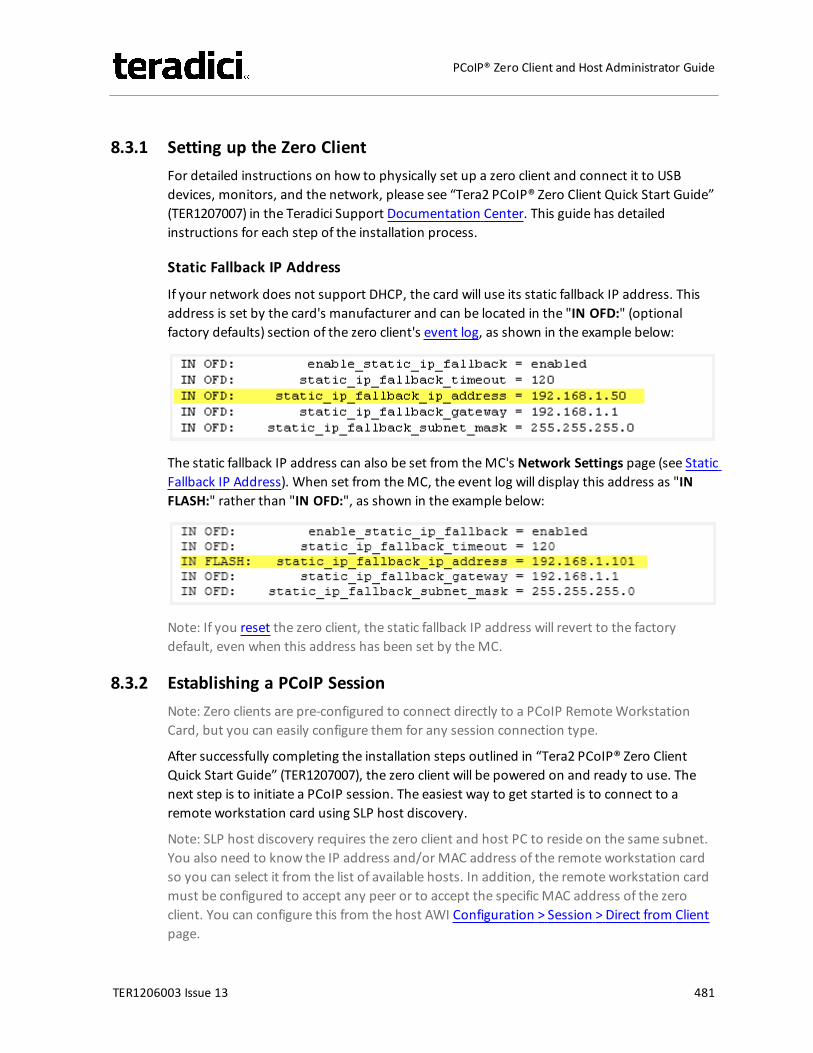
8.3.1 Setting up the Zero ClientFor detailed instructions on how to physically set up a zero client and connect it to USBdevices, monitors, and the network, please see “Tera2 PCoIP® Zero Client Quick Start Guide”(TER1207007) in the Teradici Support Documentation Center. This guide has detailedinstructions for each step of the installation process.
Static Fallback IP Address
If your network does not support DHCP, the card will use its static fallback IP address. Thisaddress is set by the card's manufacturer and can be located in the "IN OFD:" (optionalfactory defaults) section of the zero client's event log, as shown in the example below:
The static fallback IP address can also be set from theMC's Network Settings page (see StaticFallback IP Address). When set from theMC, the event log will display this address as "INFLASH:" rather than "IN OFD:", as shown in the example below:
Note: If you reset the zero client, the static fallback IP address will revert to the factorydefault, even when this address has been set by theMC.
8.3.2 Establishing a PCoIP SessionNote: Zero clients are pre-configured to connect directly to a PCoIP RemoteWorkstationCard, but you can easily configure them for any session connection type.
After successfully completing the installation steps outlined in “Tera2 PCoIP® Zero ClientQuick Start Guide” (TER1207007), the zero client will be powered on and ready to use. Thenext step is to initiate a PCoIP session. The easiest way to get started is to connect to aremote workstation card using SLP host discovery.
Note: SLP host discovery requires the zero client and host PC to reside on the same subnet.You also need to know the IP address and/or MAC address of the remote workstation cardso you can select it from the list of available hosts. In addition, the remote workstation cardmust be configured to accept any peer or to accept the specific MAC address of the zeroclient. You can configure this from the host AWI Configuration > Session > Direct from Clientpage.
TER1206003 Issue 13 481
PCoIP® Zero Client and Host Administrator Guide
To connect to a remote workstation card using SLP host discovery:
1. From theOptions > Configuration > Sessionmenu on the zero client's OSD, select theDirect to Host + SLP Host Discovery connection type, and then click OK.
2. Click the Connect button.3. When theDiscovered Hosts screen appears with a list of available hosts, select the
desired one by its IP/MAC address pair, and then click OK.4. If prompted, enter your user name and password, and then click OK.
When connected successfully, your display shows your desktop on the remote workstation,and the zero client's session LED on the front panel turns green.
To establish a session using another session connection type:
1. From the zero client's OSD, select theOptions > Configuration > Sessionmenu.2. From the Connection Type drop-down list, select the desired connection type:
l Direct to Hostl PCoIP Connection Manager (Tera2 only)l PCoIP Connection Manager + Auto-Logon (Tera2 only)l View Connection Serverl View Connection Server + Auto-Logonl View Connection Server + Kioskl View Connection Server + Imprivata OneSignl Connection Management Interface
3. After entering the required information, click OK on the Session page.4. Click the Connect button.5. If prompted, enter your user name and password.6. If you are using a brokered connection and havemore than one entitlement, select the
desired one, and then click Connect.
When connected successfully, your display shows your desktop on the remote workstation,and the zero client's session LED on the front panel turns green.
8.3.3 Other Useful LinksThe following topics providemore information about connecting zero clients and remoteworkstation cards.
l PCoIP Endpoints: Gives an overview of the PCoIP clients and hosts you can deploy inyour network.
l Connection Prerequisites: Explains the conditions that must be in place beforeconnecting PCoIP clients and hosts.
l Common LAN Scenarios: Provides a quick overview of how to connect PCoIP clients andhosts from within a LAN.
TER1206003 Issue 13 482
PCoIP® Zero Client and Host Administrator Guide
l Zero Client to RemoteWorkstation Card (LAN)l Zero Client to RemoteWorkstation Card via View Connection Server (LAN)l Zero Client to Virtual Desktop via View Connection Server (LAN)
l Common Remote Access Scenarios: Provides a quick overview of how to connect PCoIPclients and hosts remotely.l Zero Client to RemoteWorkstation Card (WAN)l Zero Client to RemoteWorkstation Card via Hardware VPN (WAN)l Zero Client to RemoteWorkstation Card via 3rd Party Broker (WAN)l Zero Client to RemoteWorkstation Card via View Security Server (WAN)l Zero Client to Virtual Desktop via View Security Server (WAN)
8.4 Uploading Firmware
8.4.1 Uploading a Firmware Release to a Zero ClientTo upload a firmware release to a zero client:
1. Log in to the client's AWI.2. From the Firmware Upload page, browse to the folder containing the firmware file.
This file will have an ".all" extension.3. Double-click the correct "*.all" firmware file.4. Click Upload.5. Click OK to confirm that you want to proceed with the upload. The operation may take
a fewminutes. When completed, the AWI page displays two buttons—Reset andContinue.
6. Click Reset.7. Click OK.
8.4.2 Upload a Firmware Release to a Remote Workstation CardTo upload a firmware release to a PCoIP RemoteWorkstation Card:
1. Ensure the host PC or workstation is in an idle state (i.e., that all applications areclosed).
2. Log into the host's AWI.3. From the Firmware Upload page, browse to the folder containing the firmware file.
This file will have an ".all" extension.4. Double-click the correct "*.all" firmware file.5. Click Upload.6. Click OK to confirm that you want to proceed with the upload. The operation may take
a fewminutes. When completed, the AWI page displays two buttons—Reset andContinue.
TER1206003 Issue 13 483
PCoIP® Zero Client and Host Administrator Guide
7. Click Reset.8. Click OK.9. Power off and then power on the host PC or workstation. It is necessary to power off
(not just restart) the PC or workstation in order for the changes to take effect on theremote workstation card.
For information on using theMC to assign a firmware release to a profile, seeMC: FirmwareManagement.
8.5 Configuring Syslog Settings
You can configure syslog settings for a host or zero client from the device's AWI, or you canuse theMC to configure settings for a device profile. Both methods are shown below.Configuration involves entering the IP address or fully qualified domain name (FQDN) for thesyslog server, and then specifying the port number and facility to use when sendingmessages to the syslog server.
Teradici uses UDP to send syslog messages to a centralized syslog server. Becausemostservers use port 514 for incoming messages, Teradici recommends you configure port 514(the default) as the syslog port to use. However, you can use a different port as long as thesyslog server is set to receive syslog messages on the same port as the device is set to sendthem.
Teradici also uses "19 – local use 3" as the default facility under the assumption that thisfacility is not commonly used. If it is being used, you can select a different facility.
Note: Cisco IOS devices, CatOS switches, and VPN 3000 concentrators use the “23 – local use7” facility. Cisco PIX firewalls use the “20 – local use 4” facility.
Note: Ensure that your syslog server can handle the volume ofmessages sent by a zeroclient. With some free syslog servers, messages can become lost if the volume is too great.
8.5.1 Setting up Syslog from the AWISyslog settings in the AWI are located in the Event Log page. To configure syslog settingsfrom the AWI for a single device:
1. From an Internet browser, enter the IP address of the PCoIP zero client or host.2. Select theDiagnostics > Event Logmenu to display the Event Log page.3. Check Enable Syslog, and then select whether you want to identify the syslog server by
its IP address or fully qualified domain name (FQDN).4. Enter the IP address or FQDN of the syslog server.5. If the syslog server is configured to receive data on a port other than 514, enter this
port number.6. If you wish the device to use a facility other than the default, select it from the Syslog
Facility drop-down list.
TER1206003 Issue 13 484
PCoIP® Zero Client and Host Administrator Guide
7. Click Apply.8. At the Success page, click Continue.
8.5.2 Setting up Syslog from the MCSyslog settings in theMC are located in theMC's Event Log page. To configure syslogsettings from theMC for a device profile:
1. From an Internet browser, enter the IP address of theMC.2. Select the Profiles tab.3. From the Profile Management page, click the Set Properties link for the desired profile.4. Expand the Event Log Control category, and then click the Edit Properties link.5. Enable Syslog Server Hostname, and then enter the IP address or FQDN of the syslog
server.6. Enable Syslog Server Port, and then enter the port number used by the syslog server
for incoming messages. The device will use this port to send messages.7. Enable Syslog Facility Number, and then enter the facility level number that the device
will use when sending messages.8. Click Save.
Note: You must enter a value in both the Syslog Server Port and Syslog Facility Numberfields.
8.6 Configuring 802.1x Network Device Authentication
8.6.1 PrerequisitesAn 802.1x authentication system requires the following components:
l PCoIP zero client with firmware 4.0.3 or newerl PCoIP Management Console 1.8.1 or newerl Windows Server 2008 R2with AD DS (Active Directory Domain Services)l Windows Server 2008 R2with AD CS (Active Directory Certificate Services)l Windows Server 2008 R2with NPS (Network Policy and Access Services)l View Connection Serverl A switch with 802.1x support configured
8.6.2 Procedure
Overview
Configuring 802.1x device authentication entails the following steps:
1. In theWindows 2008 server, create a client user.2. In the Certificate Authority (CA) server, export the root CA certificate.
TER1206003 Issue 13 485
PCoIP® Zero Client and Host Administrator Guide
3. In the CA server, create a certificate template for client authentication.4. From the CAWeb Enrollment interface interface for the certificate server, issue the
client certificate.5. From themachine on which you issued the certificate, export the client certificate.6. Using OpenSSL, convert the certificate format from .pfx to .pem.7. In theWindows 2008 server, import the client certificate into the client user account.8. From theMC or device's AWI, import the certificates.
Note: The instructions in the following sections are based on Windows Server 2008 R2. If youare using a newer version ofWindows Server, the steps may vary slightly.
Create a Client User
1. Log in to theWindows 2008 server.2. Click Start > Administrative Tools > Server Manager.3. Navigate to Roles > Active Directory Domain Services > Active Directory Users and
Computers > <domain.local> > Users.4. Right-click Users, select New > User, and then follow the wizard.
Export the Root CA Certificate
1. Log in to the Certificate Authority (CA) server.2. Open a Microsoft Management Console window (e.g.,entermmc.exe in the Startmenu
search field).3. From the console window, select File > Add/Remove Snap-in.4. Add the Certificates snap-in, selecting Computer account and then Local computer.5. Click Finish, and then OK to close the Add or Remove Snap-ins dialog.6. From the console, select Certificates (Local Computer) > Trusted Root Certification
Authorities > Certificates.7. In the right panel, right-click the certificate, and then select All Tasks > Export.8. Follow the wizard to export the certificate:
a. Select Base-64 encoded X.509 (.CER).b. Click Browse, specify a name and location for the certificate, and then click Save.c. Click Finish, and then OK.
Create a Certificate Template for Client Authentication
1. From the CA server, click Start > Administrative Tools > Certification Authority.2. Expand the tree for your CA.3. Right-click Certificate Templates, and then clickManage.4. Right-click the Computer template, and then click Duplicate Template.
TER1206003 Issue 13 486
PCoIP® Zero Client and Host Administrator Guide
5. Configure the template as follows:a. From the Compatibility tab, selectWindows Server 2003.b. From theGeneral tab, enter a name for the template (e.g., "zero client 802.1x") and
change the validity period to match the organization's security policy.c. From the Request Handling tab, select Allow private key to be exported.d. From the Subject Name tab, select Supply in the request.e. From the Security tab, select the user who will be requesting the certificate, and
then give Enroll permission to this user.f. Click OK and close the Certificate Templates Consolewindow.
6. From the Certification Authoritywindow, .right-click Certificate Templates, selectNew, and then click Certificate Template to Issue
7. Select the certificate you just created (i.e., "zero client 802.1x), and then click OK. Thetemplate will now appear in the Certificate Templates list.
8. Close the window.
Issue the Client Certificate
Note: Do not use any other browser except Internet Explorer to log into the certificate server.
1. Using Internet Explorer on your local machine, go to your Certificate Authority URLusing the format https://<server>/certsrv/ (e.g., "https://ca.domain.local/certsrv/").
2. Click Request a certificate and then advanced certificate request.3. Click Create and submit a request to this CA.4. At the pop-up window, click Yes.5. Fill out the Advanced Certificate Request form as follows:
a. In the Certificate Template section, select the certificate for clients (e.g., "ZeroClient 802.1x").
b. In the Identifying Information for Offline Template section, enter the accountname in theName field. The other fields are not required.Important! The name you enter in the Name field must be the universal principalname (UPN) of the client user you created in Create a Client User (e.g.,"[email protected]").
c. In the Additional Options section, set the Request Format to PKCS10.d. If desired, enter a name in the Friendly Name field.e. Click Submit, and then Yes at the pop-up window.f. At the Certificate Issuedwindow, click Install this certificate.
Export the Client Certificate
1. From themachine on which you issued the certificate, open a Microsoft ManagementConsole window (e.g., entermmc.exe in the Startmenu search field).
2. From the console window, select File > Add/Remove Snap-in.3. Add the Certificates snap-in, selectingMy user account.
TER1206003 Issue 13 487
PCoIP® Zero Client and Host Administrator Guide
4. Click Finish, and then OK to close the Add or Remove Snap-ins dialog.5. Select Certificates - Current User > Personal > Certificates.6. In the right panel, right-click the certificate, and then select All Tasks > Export.7. Follow the wizard to export the certificate:
a. Click Yes, export the private key.b. Select Personal Information Exchange - PKCS #12 (.PFX).c. Enter a password for the certificate.d. Click Browse, specify a name and location for the certificate, and then click Save.e. Click Finish, and then OK.
8. Repeat steps 5 to 7 again to export the zero client certificate, but this timewithout theprivate key (No, do not export the private key), selecting theDER encoded binaryX.509 (.CER) format instead of the PKCS format.
9. Save this .cer file to a location where it can be accessed by theWindows 2008 serverand imported into Active Directory.
Convert the Certificate Format from .pfx to .pem
1. Download and install Windows OpenSSL fromhttp://www.slproweb.com/products/Win32OpenSSL.html. (The light version issufficient.)
2. Copy the .pfx client certificate file you saved above to the C:\OpenSSL-Win32\bindirectory.
3. Open a command prompt window, and then enter the following command to convertthe certificate format from .pfx to .pem:C:\OpenSSL-Win32\bin\openssl.exe pkcs12 -in <client_cert>.pfx -out <client_cert>.pem -nodeswhere <client_cert> is the name of the .pfx certificate file you saved to your localmachine.
4. When prompted, enter the password for the certificate file.5. At the command prompt, enter the following command to create an RSA private key
file:C:\OpenSSL-Win32\bin\openssl.exe rsa –in <client_cert>.pem –out < client_cert>_rsa.pemwhere <client_cert> is the name of the .pem certificate file you created in the previousstep.
6. In Notepad:a. Open both the original .pem file and the RSA .pem file you just created. The RSA
.pem file contains only an RSA private key. Because the zero client certificaterequires its private key in RSA format, you need to replace its private key with thisRSA private key.
b. Copy the entire contents of the RSA .pem file (everything from -----BEGIN RSAPRIVATE KEY ----- to -----END RSA PRIVATE KEY-----), and paste it into the original
TER1206003 Issue 13 488
PCoIP® Zero Client and Host Administrator Guide
.pem file, replacing its private key with this RSA private key.
In other words, make sure that all the text from -----BEGIN PRIVATE KEY----- to -----END PRIVATE KEY (including the dashes) in the original .pem file is replaced withthe contents of -----BEGIN RSA PRIVATE KEY ----- to -----END RSA PRIVATE KEY-----(including the dashes) from the RSA .pem file
c. Save the original .pem file and close it. The certificate is now ready to be uploadedto the zero client.
Import the Client Certificate into the Client User Account
1. Log in to theWindows 2008 server.2. Click Start > Administrative Tools > Active Directory Users and Computers.3. From the Viewmenu, select Advanced Features.4. Navigate to the user you created for the zero client.5. Right-click the user, and then select Name Mappings.6. In the X.509 Certificates section, click Add.7. Locate and select the zero client certificate you exported that does not contain the
private key (This file was saved to a network location in Step 9 of Export the ClientCertificate.)
8. Leave both identity boxes checked, click OK, and then click OK again.
Import the Certificates to Client Device
To import the certificates into a profile using theManagement Console (MC):
1. From a browser, enter the IP address of theMC web page, and then log in to theMC.2. From the Profiles tab, click Add New, and then enter a name for the new profile.3. Click Save to save the profile.4. Click Set Properties to edit the new profile's configuration.5. In the Certificate Store category, click + to expand it, and then click Add New.6. In the Add Certificate to Store dialog, click Browse, and then upload both the root CA
certificate and the certificate with the private key.7. For the zero client certificate, select 802.1X from the drop-down list.8. Expand the Security Configuration category, and then click Edit Properties.9. Select Enable 802.1x Security, and then set the value to True.10. Select 802.1x Authentication Identity, enter the user name you have defined for the
zero client, and then click Save.11. Apply this profile to the desired group.
To import the certificates to a device using the AWI:
1. From a browser, log into the AWI for the zero client or remote workstation card.2. From the AWI menu, select Upload > Certificate.
TER1206003 Issue 13 489
PCoIP® Zero Client and Host Administrator Guide
3. Upload both the Root CA certificate and the certificate with the private key, using theBrowse button to locate each certificate and theUpload button to upload them.
4. From the AWI menu, select Configuration > Network.5. Select Enable 802.1x Security.6. Click the Choose button beside the Client Certificate field.7. Select the certificate with the private key, and then click Select.8. Enter the identity name of the certificate. Typically, this is the universal principal name
(UPN) that appears after Subject: (e.g., "[email protected]").
Note: For the identity, your Windows server may be configured to use the certificate'sSubject, the Subject Alternative Name, or another field. Please check with youradministrator.
9. Click Apply, and then Reset.
For more information about 802.1x, please see the following Knowledge Base topics in theTeradici Support Site:
l Support for 802.1x on zero clients: KB 15134-590l Setting up Windows Server 2008 R2 as an 802.1x authentication server: KB 15134-1245l General 802.1x troubleshooting steps: KB 15134-928
8.7 Setting up a Touch Screen Display
These instructions explain how to install an Elo TouchSystems touch screen display, how toconfigure the firmware if you want the touch screen to be controlled by a driver running onthe host, and how to set up auto-logon to bypass authentication when users are connectingto a host with a broker.
8.7.1 Installing the Touch Screen to the Zero Client1. Plug in the touch screen's USB cable to the zero client's USB port.2. Attach themonitor cable from the touch screen to any port on the zero client.
Note: You cannot attach multiple touch screens to the zero client, but you can attach anon-touch screen monitor to the zero client in addition to the touch screen as long asthe touch screen is attached to the port on the zero client that is configured as theprimary port.
3. Plug in the power.4. Disconnect the zero client session. This initiates the calibration on the touch screen.
Note: Once the touch screen is calibrated, the co-ordinates are saved in flash memory.You can manually recalibrate the screen as required through the OSD Touch Screenpage.
TER1206003 Issue 13 490
PCoIP® Zero Client and Host Administrator Guide
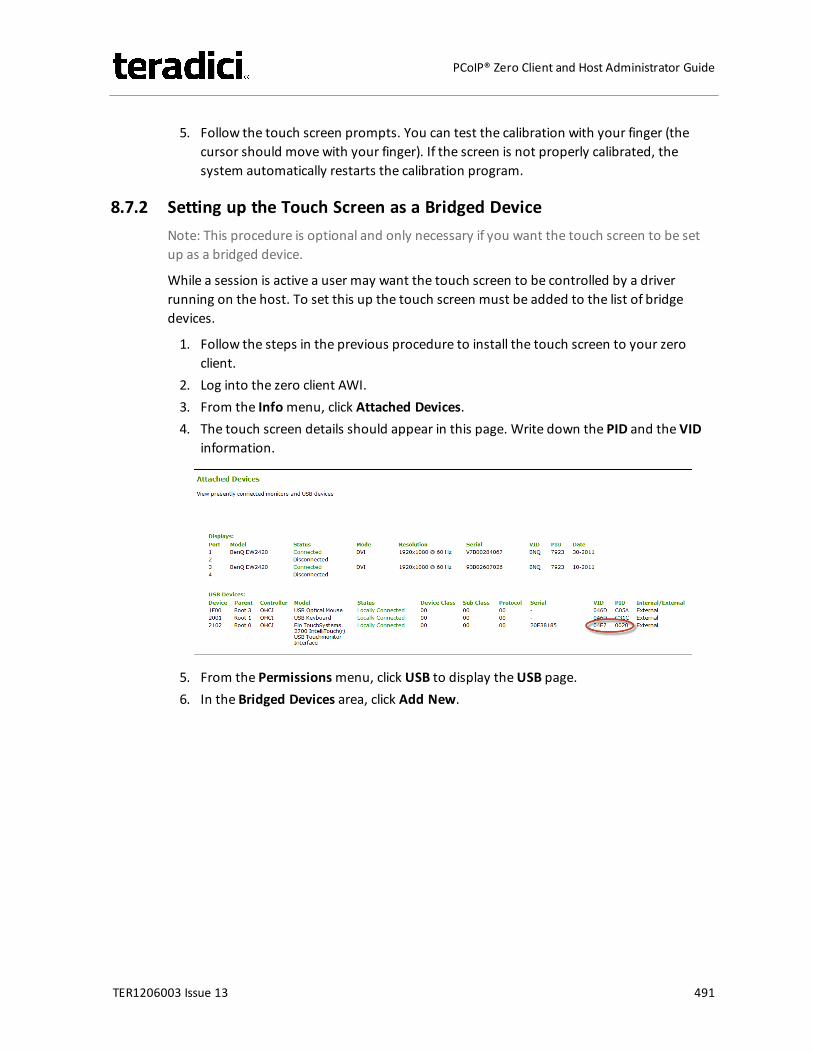
5. Follow the touch screen prompts. You can test the calibration with your finger (thecursor should move with your finger). If the screen is not properly calibrated, thesystem automatically restarts the calibration program.
8.7.2 Setting up the Touch Screen as a Bridged DeviceNote: This procedure is optional and only necessary if you want the touch screen to be setup as a bridged device.
While a session is active a user may want the touch screen to be controlled by a driverrunning on the host. To set this up the touch screen must be added to the list of bridgedevices.
1. Follow the steps in the previous procedure to install the touch screen to your zeroclient.
2. Log into the zero client AWI.3. From the Infomenu, click Attached Devices.4. The touch screen details should appear in this page. Write down the PID and the VID
information.
5. From the Permissionsmenu, click USB to display theUSB page.6. In the Bridged Devices area, click Add New.
TER1206003 Issue 13 491
PCoIP® Zero Client and Host Administrator Guide
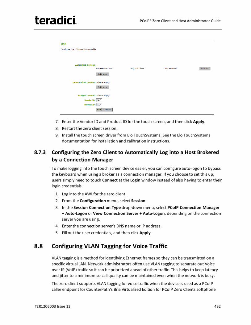
7. Enter the Vendor ID and Product ID for the touch screen, and then click Apply.8. Restart the zero client session.9. Install the touch screen driver from Elo TouchSystems. See the Elo TouchSystems
documentation for installation and calibration instructions.
8.7.3 Configuring the Zero Client to Automatically Log into a Host Brokeredby a Connection ManagerTo make logging into the touch screen device easier, you can configure auto-logon to bypassthe keyboard when using a broker as a connection manager. If you choose to set this up,users simply need to touch Connect at the Loginwindow instead of also having to enter theirlogin credentials.
1. Log into the AWI for the zero client.2. From the Configurationmenu, select Session.3. In the Session Connection Type drop-down menu, select PCoIP Connection Manager
+ Auto-Logon or View Connection Server + Auto-Logon, depending on the connectionserver you are using.
4. Enter the connection server's DNS name or IP address.5. Fill out the user credentials, and then click Apply.
8.8 Configuring VLAN Tagging for Voice Traffic
VLAN tagging is a method for identifying Ethernet frames so they can be transmitted on aspecific virtual LAN. Network administrators often use VLAN tagging to separate out Voiceover IP (VoIP) traffic so it can be prioritized ahead of other traffic. This helps to keep latencyand jitter to a minimum so call quality can bemaintained even when the network is busy.
The zero client supports VLAN tagging for voice traffic when the device is used as a PCoIPcaller endpoint for CounterPath's Bria Virtualized Edition for PCoIP Zero Clients softphone
TER1206003 Issue 13 492
PCoIP® Zero Client and Host Administrator Guide
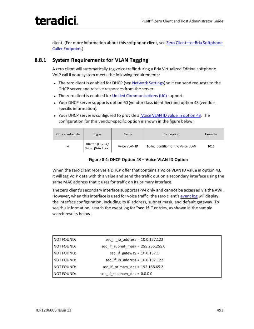
client. (For more information about this softphone client, see Zero Client–to–Bria SoftphoneCaller Endpoint.)
8.8.1 System Requirements for VLAN TaggingA zero client will automatically tag voice traffic during a Bria Virtualized Edition softphoneVoIP call if your system meets the following requirements:
l The zero client is enabled for DHCP (see Network Settings) so it can send requests to theDHCP server and receive responses from the server.
l The zero client is enabled for Unified Communications (UC) support.l Your DHCP server supports option 60 (vendor class identifier) and option 43 (vendor-
specific information).l Your DHCP server is configured to provide a Voice VLAN ID value in option 43. The
configuration for this vendor-specific option is shown in the figure below:
Figure 8-4: DHCP Option 43 – Voice VLAN ID Option
When the zero client receives a DHCP offer that contains a Voice VLAN ID value in option 43,it will tag VoIP data with this value and send the traffic out on a secondary interface using thesameMAC address that it uses for traffic on its primary interface.
The zero client's secondary interface supports IPv4 only and cannot be accessed via the AWI.However, when this interface is used for voice traffic, the zero client's event log will displaythe interface configuration, including its IP address, subnet mask, and default gateway. Tosee this information, search the event log for "sec_if_" entries, as shown in the samplesearch results below.
NOT FOUND: sec_if_ip_address = 10.0.157.122
NOT FOUND: sec_if_subnet_mask = 255.255.255.0
NOT FOUND: sec_if_gateway = 10.0.157.1
NOT FOUND: sec_if_ip_address = 10.0.157.122
NOT FOUND: sec_if_primary_dns = 192.168.65.2
NOT FOUND: sec_if_seconary_dns = 0.0.0.0
TER1206003 Issue 13 493
PCoIP® Zero Client and Host Administrator Guide
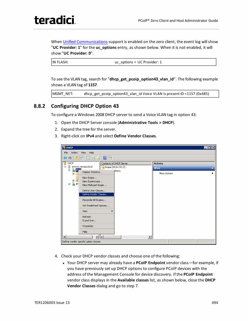
When Unified Communications support is enabled on the zero client, the event log will show"UC Provider: 1" for the uc_options entry, as shown below. When it is not enabled, it willshow "UC Provider: 0".
IN FLASH: uc_options = UC Provider: 1
To see the VLAN tag, search for "dhcp_get_pcoip_option43_vlan_id". The following exampleshows a VLAN tag of 1157.
MGMT_NET: dhcp_get_pcoip_option43_vlan_id Voice VLAN is present ID =1157 (0x485)
8.8.2 Configuring DHCP Option 43To configure aWindows 2008 DHCP server to send a Voice VLAN tag in option 43:
1. Open the DHCP Server console (Administrative Tools > DHCP).2. Expand the tree for the server.3. Right-click on IPv4 and select Define Vendor Classes.
4. Check your DHCP vendor classes and choose one of the following:l Your DHCP server may already have a PCoIP Endpoint vendor class—for example, if
you have previously set up DHCP options to configure PCoIP devices with theaddress of theManagement Console for device discovery. If the PCoIP Endpointvendor class displays in the Available classes list, as shown below, close theDHCPVendor Classes dialog and go to step 7.
TER1206003 Issue 13 494
PCoIP® Zero Client and Host Administrator Guide
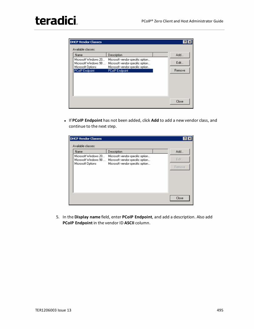
l If PCoIP Endpoint has not been added, click Add to add a new vendor class, andcontinue to the next step.
5. In theDisplay name field, enter PCoIP Endpoint, and add a description. Also addPCoIP Endpoint in the vendor ID ASCII column.
TER1206003 Issue 13 495
PCoIP® Zero Client and Host Administrator Guide
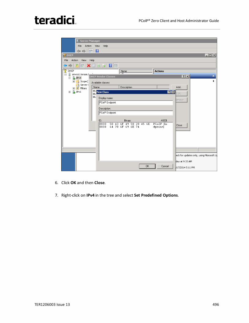
6. Click OK and then Close.
7. Right-click on IPv4 in the tree and select Set Predefined Options.
TER1206003 Issue 13 496
PCoIP® Zero Client and Host Administrator Guide
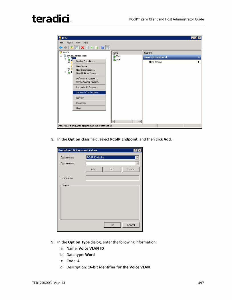
8. In theOption class field, select PCoIP Endpoint, and then click Add.
9. In theOption Type dialog, enter the following information:a. Name: Voice VLAN IDb. Data type:Wordc. Code: 4d. Description: 16-bit identifier for the Voice VLAN
TER1206003 Issue 13 497
PCoIP® Zero Client and Host Administrator Guide
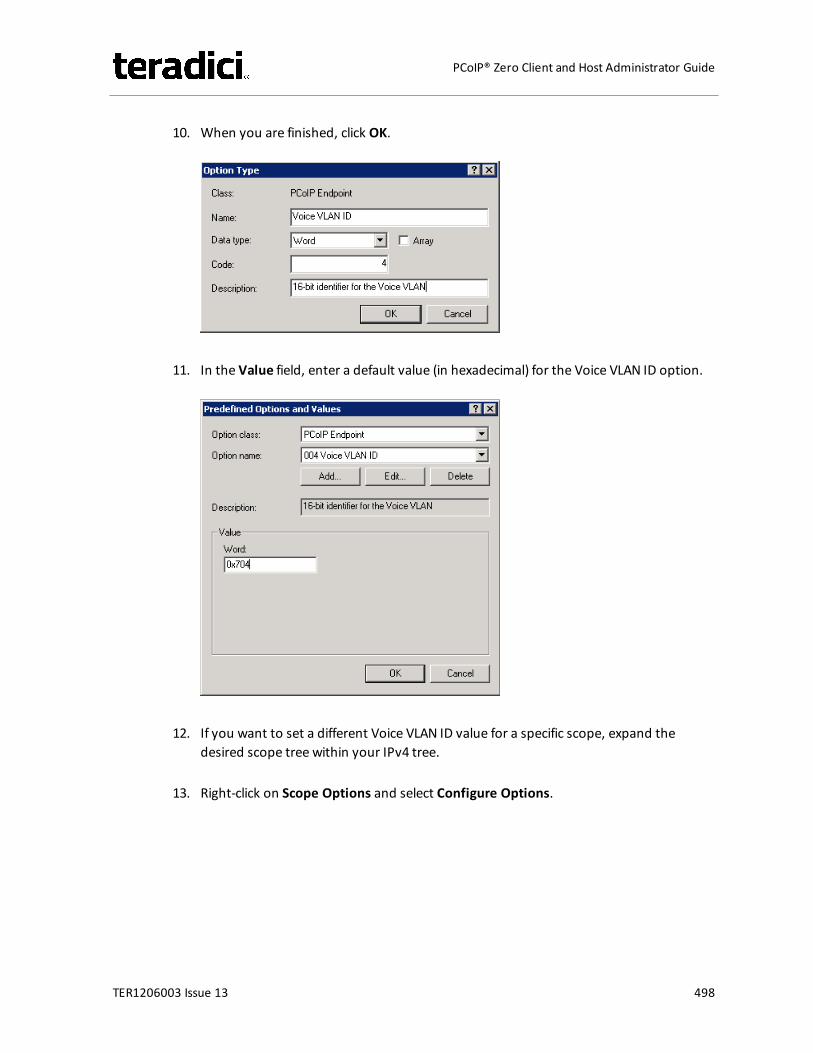
10. When you are finished, click OK.
11. In the Value field, enter a default value (in hexadecimal) for the Voice VLAN ID option.
12. If you want to set a different Voice VLAN ID value for a specific scope, expand thedesired scope tree within your IPv4 tree.
13. Right-click on Scope Options and select Configure Options.
TER1206003 Issue 13 498
PCoIP® Zero Client and Host Administrator Guide
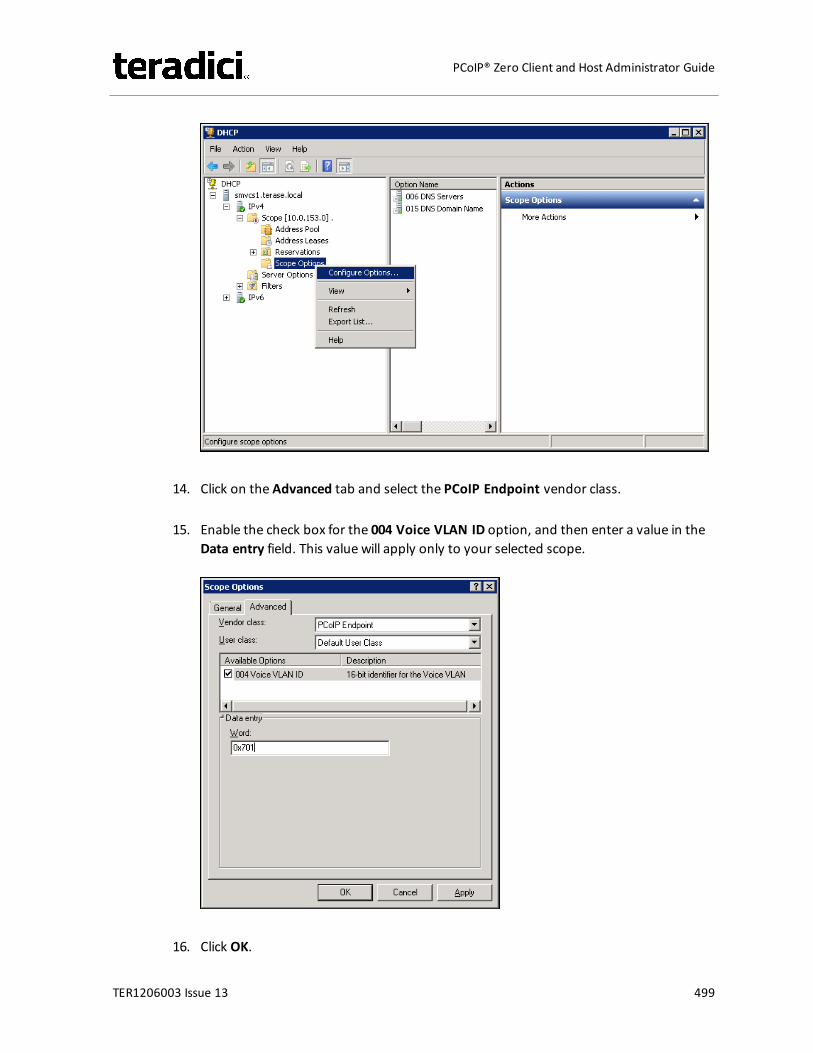
14. Click on the Advanced tab and select the PCoIP Endpoint vendor class.
15. Enable the check box for the 004 Voice VLAN ID option, and then enter a value in theData entry field. This value will apply only to your selected scope.
16. Click OK.
TER1206003 Issue 13 499
PCoIP® Zero Client and Host Administrator Guide
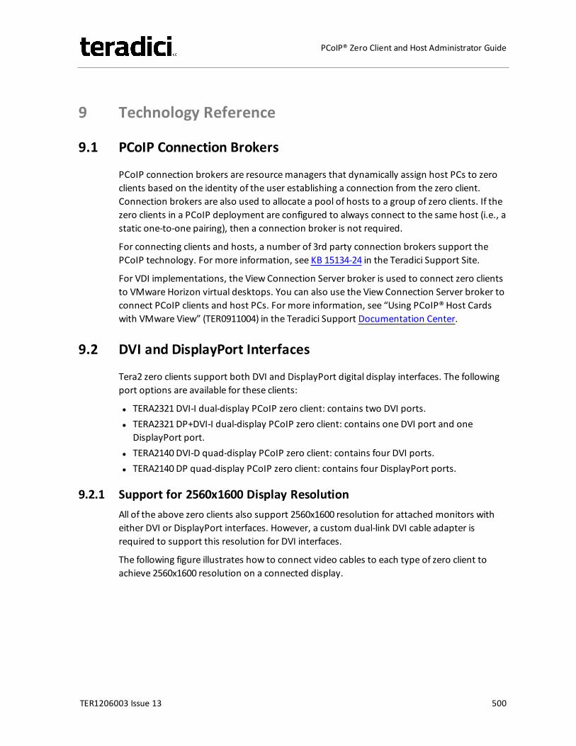
9 Technology Reference
9.1 PCoIP Connection Brokers
PCoIP connection brokers are resourcemanagers that dynamically assign host PCs to zeroclients based on the identity of the user establishing a connection from the zero client.Connection brokers are also used to allocate a pool of hosts to a group of zero clients. If thezero clients in a PCoIP deployment are configured to always connect to the same host (i.e., astatic one-to-one pairing), then a connection broker is not required.
For connecting clients and hosts, a number of 3rd party connection brokers support thePCoIP technology. For more information, see KB 15134-24 in the Teradici Support Site.
For VDI implementations, the View Connection Server broker is used to connect zero clientsto VMware Horizon virtual desktops. You can also use the View Connection Server broker toconnect PCoIP clients and host PCs. For more information, see “Using PCoIP® Host Cardswith VMware View” (TER0911004) in the Teradici Support Documentation Center.
9.2 DVI and DisplayPort Interfaces
Tera2 zero clients support both DVI and DisplayPort digital display interfaces. The followingport options are available for these clients:
l TERA2321 DVI-I dual-display PCoIP zero client: contains two DVI ports.l TERA2321 DP+DVI-I dual-display PCoIP zero client: contains one DVI port and one
DisplayPort port.l TERA2140 DVI-D quad-display PCoIP zero client: contains four DVI ports.l TERA2140 DP quad-display PCoIP zero client: contains four DisplayPort ports.
9.2.1 Support for 2560x1600 Display ResolutionAll of the above zero clients also support 2560x1600 resolution for attached monitors witheither DVI or DisplayPort interfaces. However, a custom dual-link DVI cable adapter isrequired to support this resolution for DVI interfaces.
The following figure illustrates how to connect video cables to each type of zero client toachieve 2560x1600 resolution on a connected display.
TER1206003 Issue 13 500
PCoIP® Zero Client and Host Administrator Guide
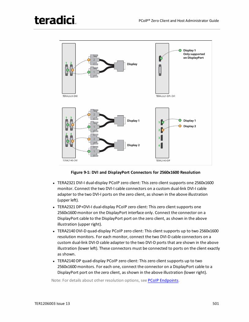
Figure 9-1: DVI and DisplayPort Connectors for 2560x1600 Resolution
l TERA2321 DVI-I dual-display PCoIP zero client: This zero client supports one 2560x1600monitor. Connect the two DVI-I cable connectors on a custom dual-link DVI-I cableadapter to the two DVI-I ports on the zero client, as shown in the above illustration(upper left).
l TERA2321 DP+DVI-I dual-display PCoIP zero client: This zero client supports one2560x1600monitor on the DisplayPort interface only. Connect the connector on aDisplayPort cable to the DisplayPort port on the zero client, as shown in the aboveillustration (upper right).
l TERA2140 DVI-D quad-display PCoIP zero client: This client supports up to two 2560x1600resolution monitors. For each monitor, connect the two DVI-D cable connectors on acustom dual-link DVI-D cable adapter to the two DVI-D ports that are shown in the aboveillustration (lower left). These connectors must be connected to ports on the client exactlyas shown.
l TERA2140 DP quad-display PCoIP zero client: This zero client supports up to two2560x1600monitors. For each one, connect the connector on a DisplayPort cable to aDisplayPort port on the zero client, as shown in the above illustration (lower right).
Note: For details about other resolution options, see PCoIP Endpoints.
TER1206003 Issue 13 501
PCoIP® Zero Client and Host Administrator Guide
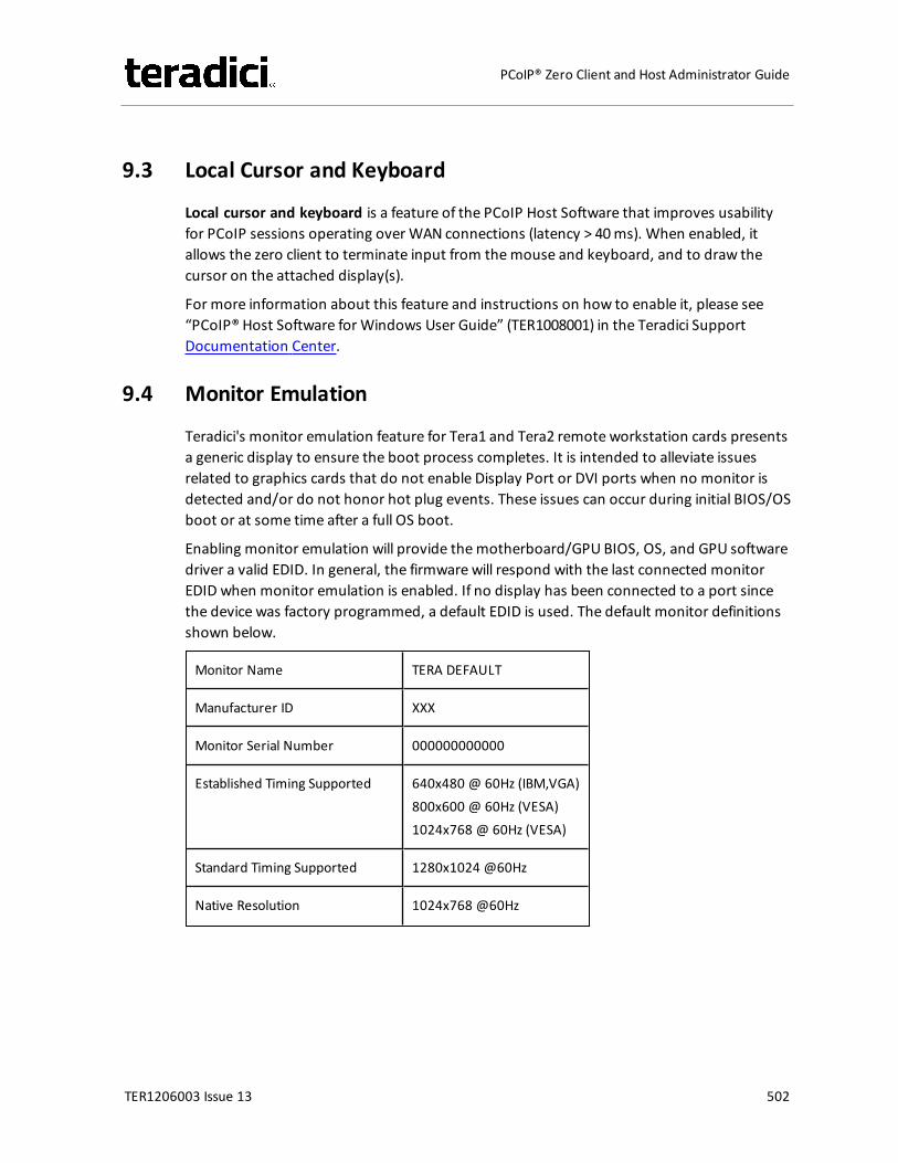
9.3 Local Cursor and Keyboard
Local cursor and keyboard is a feature of the PCoIP Host Software that improves usabilityfor PCoIP sessions operating over WAN connections (latency > 40ms). When enabled, itallows the zero client to terminate input from themouse and keyboard, and to draw thecursor on the attached display(s).
For more information about this feature and instructions on how to enable it, please see“PCoIP® Host Software for Windows User Guide” (TER1008001) in the Teradici SupportDocumentation Center.
9.4 Monitor Emulation
Teradici's monitor emulation feature for Tera1 and Tera2 remote workstation cards presentsa generic display to ensure the boot process completes. It is intended to alleviate issuesrelated to graphics cards that do not enable Display Port or DVI ports when no monitor isdetected and/or do not honor hot plug events. These issues can occur during initial BIOS/OSboot or at some time after a full OS boot.
Enabling monitor emulation will provide themotherboard/GPU BIOS, OS, and GPU softwaredriver a valid EDID. In general, the firmware will respond with the last connected monitorEDID when monitor emulation is enabled. If no display has been connected to a port sincethe device was factory programmed, a default EDID is used. The default monitor definitionsshown below.
Monitor Name TERA DEFAULT
Manufacturer ID XXX
Monitor Serial Number 000000000000
Established Timing Supported 640x480 @ 60Hz (IBM,VGA)800x600 @ 60Hz (VESA)1024x768 @ 60Hz (VESA)
Standard Timing Supported 1280x1024 @60Hz
Native Resolution 1024x768 @60Hz
TER1206003 Issue 13 502
PCoIP® Zero Client and Host Administrator Guide
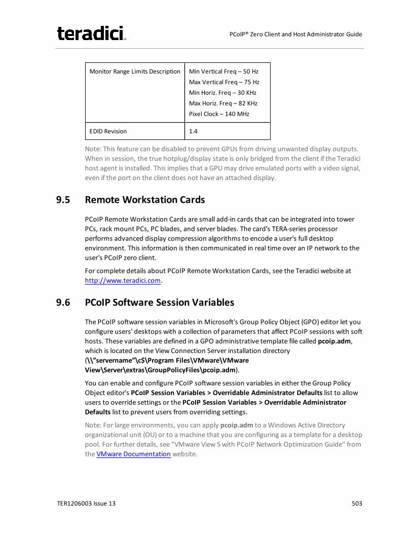
Monitor Range Limits Description Min Vertical Freq – 50 HzMax Vertical Freq – 75 HzMin Horiz. Freq – 30 KHzMax Horiz. Freq – 82 KHzPixel Clock – 140 MHz
EDID Revision 1.4
Note: This feature can be disabled to prevent GPUs from driving unwanted display outputs.When in session, the true hotplug/display state is only bridged from the client if the Teradicihost agent is installed. This implies that a GPUmay drive emulated ports with a video signal,even if the port on the client does not have an attached display.
9.5 Remote Workstation Cards
PCoIP RemoteWorkstation Cards are small add-in cards that can be integrated into towerPCs, rack mount PCs, PC blades, and server blades. The card's TERA-series processorperforms advanced display compression algorithms to encode a user's full desktopenvironment. This information is then communicated in real time over an IP network to theuser's PCoIP zero client.
For complete details about PCoIP RemoteWorkstation Cards, see the Teradici website athttp://www.teradici.com.
9.6 PCoIP Software Session Variables
The PCoIP software session variables in Microsoft's Group Policy Object (GPO) editor let youconfigure users' desktops with a collection of parameters that affect PCoIP sessions with softhosts. These variables are defined in a GPO administrative template file called pcoip.adm,which is located on the View Connection Server installation directory(\\”servername”\c$\Program Files\VMware\VMwareView\Server\extras\GroupPolicyFiles\pcoip.adm).
You can enable and configure PCoIP software session variables in either the Group PolicyObject editor's PCoIP Session Variables > Overridable Administrator Defaults list to allowusers to override settings or the PCoIP Session Variables > Overridable AdministratorDefaults list to prevent users from overriding settings.
Note: For large environments, you can apply pcoip.adm to a Windows Active Directoryorganizational unit (OU) or to a machine that you are configuring as a template for a desktoppool. For further details, see "VMware View 5with PCoIP Network Optimization Guide" fromthe VMware Documentation website.
TER1206003 Issue 13 503
PCoIP® Zero Client and Host Administrator Guide
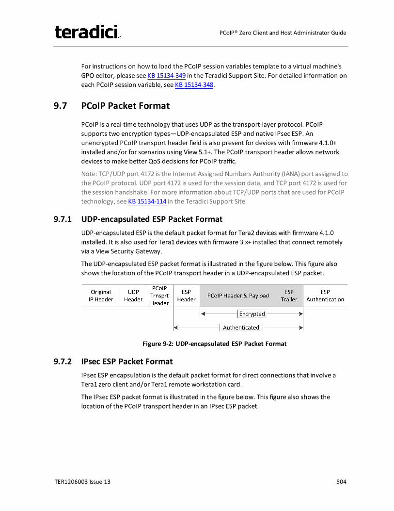
For instructions on how to load the PCoIP session variables template to a virtual machine'sGPO editor, please see KB 15134-349 in the Teradici Support Site. For detailed information oneach PCoIP session variable, see KB 15134-348.
9.7 PCoIP Packet Format
PCoIP is a real-time technology that uses UDP as the transport-layer protocol. PCoIPsupports two encryption types—UDP-encapsulated ESP and native IPsec ESP. Anunencrypted PCoIP transport header field is also present for devices with firmware 4.1.0+installed and/or for scenarios using View 5.1+. The PCoIP transport header allows networkdevices to make better QoS decisions for PCoIP traffic.
Note: TCP/UDP port 4172 is the Internet Assigned Numbers Authority (IANA) port assigned tothe PCoIP protocol. UDP port 4172 is used for the session data, and TCP port 4172 is used forthe session handshake. For more information about TCP/UDP ports that are used for PCoIPtechnology, see KB 15134-114 in the Teradici Support Site.
9.7.1 UDP-encapsulated ESP Packet FormatUDP-encapsulated ESP is the default packet format for Tera2 devices with firmware 4.1.0installed. It is also used for Tera1 devices with firmware 3.x+ installed that connect remotelyvia a View Security Gateway.
The UDP-encapsulated ESP packet format is illustrated in the figure below. This figure alsoshows the location of the PCoIP transport header in a UDP-encapsulated ESP packet.
Figure 9-2: UDP-encapsulated ESP Packet Format
9.7.2 IPsec ESP Packet FormatIPsec ESP encapsulation is the default packet format for direct connections that involve aTera1 zero client and/or Tera1 remote workstation card.
The IPsec ESP packet format is illustrated in the figure below. This figure also shows thelocation of the PCoIP transport header in an IPsec ESP packet.
TER1206003 Issue 13 504
PCoIP® Zero Client and Host Administrator Guide
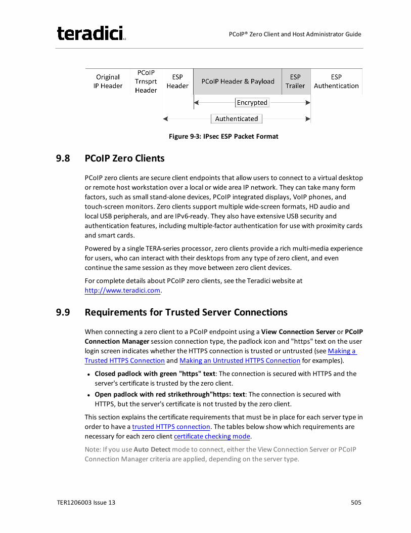
Figure 9-3: IPsec ESP Packet Format
9.8 PCoIP Zero Clients
PCoIP zero clients are secure client endpoints that allow users to connect to a virtual desktopor remote host workstation over a local or wide area IP network. They can takemany formfactors, such as small stand-alone devices, PCoIP integrated displays, VoIP phones, andtouch-screen monitors. Zero clients support multiple wide-screen formats, HD audio andlocal USB peripherals, and are IPv6-ready. They also have extensive USB security andauthentication features, including multiple-factor authentication for use with proximity cardsand smart cards.
Powered by a single TERA-series processor, zero clients provide a rich multi-media experiencefor users, who can interact with their desktops from any type of zero client, and evencontinue the same session as they move between zero client devices.
For complete details about PCoIP zero clients, see the Teradici website athttp://www.teradici.com.
9.9 Requirements for Trusted Server Connections
When connecting a zero client to a PCoIP endpoint using a View Connection Server or PCoIPConnection Manager session connection type, the padlock icon and "https" text on the userlogin screen indicates whether the HTTPS connection is trusted or untrusted (seeMaking aTrusted HTTPS Connection and Making an Untrusted HTTPS Connection for examples).
l Closed padlock with green "https" text: The connection is secured with HTTPS and theserver's certificate is trusted by the zero client.
l Open padlock with red strikethrough"https: text: The connection is secured withHTTPS, but the server's certificate is not trusted by the zero client.
This section explains the certificate requirements that must be in place for each server type inorder to have a trusted HTTPS connection. The tables below showwhich requirements arenecessary for each zero client certificate checking mode.
Note: If you use Auto Detectmode to connect, either the View Connection Server or PCoIPConnection Manager criteria are applied, depending on the server type.
TER1206003 Issue 13 505
PCoIP® Zero Client and Host Administrator Guide
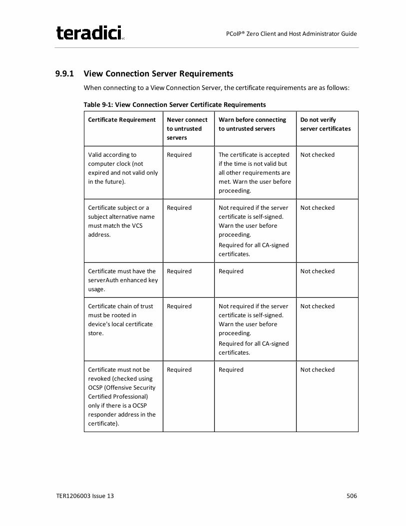
9.9.1 View Connection Server RequirementsWhen connecting to a View Connection Server, the certificate requirements are as follows:
Table 9-1: View Connection Server Certificate Requirements
Certificate Requirement Never connectto untrustedservers
Warn before connectingto untrusted servers
Do not verifyserver certificates
Valid according tocomputer clock (notexpired and not valid onlyin the future).
Required The certificate is acceptedif the time is not valid butall other requirements aremet. Warn the user beforeproceeding.
Not checked
Certificate subject or asubject alternative namemust match the VCSaddress.
Required Not required if the servercertificate is self-signed.Warn the user beforeproceeding.Required for all CA-signedcertificates.
Not checked
Certificate must have theserverAuth enhanced keyusage.
Required Required Not checked
Certificate chain of trustmust be rooted indevice's local certificatestore.
Required Not required if the servercertificate is self-signed.Warn the user beforeproceeding.Required for all CA-signedcertificates.
Not checked
Certificate must not berevoked (checked usingOCSP (Offensive SecurityCertified Professional)only if there is a OCSPresponder address in thecertificate).
Required Required Not checked
TER1206003 Issue 13 506
PCoIP® Zero Client and Host Administrator Guide
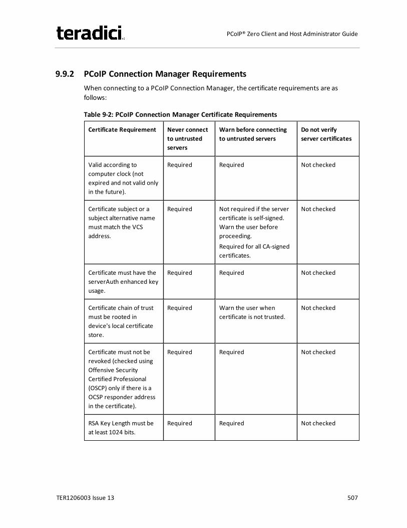
9.9.2 PCoIP Connection Manager RequirementsWhen connecting to a PCoIP Connection Manager, the certificate requirements are asfollows:
Table 9-2: PCoIP Connection Manager Certificate Requirements
Certificate Requirement Never connectto untrustedservers
Warn before connectingto untrusted servers
Do not verifyserver certificates
Valid according tocomputer clock (notexpired and not valid onlyin the future).
Required Required Not checked
Certificate subject or asubject alternative namemust match the VCSaddress.
Required Not required if the servercertificate is self-signed.Warn the user beforeproceeding.Required for all CA-signedcertificates.
Not checked
Certificate must have theserverAuth enhanced keyusage.
Required Required Not checked
Certificate chain of trustmust be rooted indevice's local certificatestore.
Required Warn the user whencertificate is not trusted.
Not checked
Certificate must not berevoked (checked usingOffensive SecurityCertified Professional(OSCP) only if there is aOCSP responder addressin the certificate).
Required Required Not checked
RSA Key Length must beat least 1024 bits.
Required Required Not checked
TER1206003 Issue 13 507
PCoIP® Zero Client and Host Administrator Guide
9.10 Syslog
The syslog protocol is a standard for logging program messages to a database. It iscommonly used to monitor devices that do not have a large amount of storage capacity,such as networking devices, ESX servers, zero clients, and PCoIP RemoteWorkstation Cards.Using syslog for logging allows you to centralize the storage of log messages and to captureand maintain a longer history of log data. It also provides a set of tools to filter and report onsyslog data.
Syslog messages include a facility level (from decimal 0 to 23) that indicates the application oroperating system component that is generating the log message. For example, a facility levelof "0" indicates a kernel message, a facility level of "1" indicates a user-level message, and afacility level of "2" indicates a message from a mail system. Processes and daemons thathave not been explicitly assigned a facility may use any of the eight "local use" facilities ("16 –local use 0" to "23 – local use 7") or they may use the "1 – user-level" facility. Facilities allowfor easy filtering ofmessages generated by a device.
Syslog messages are also assigned a severity level from 0 to 7, where a severity level of "0"indicates an emergency panic condition and a severity level of "7" indicates a debug-levelmessage useful to developers but not for operations.
See Configuring Syslog Settings in the"How To" section for information on how to configuresyslog from the AWI and MC.
9.11 Teradici PCoIP Hardware Accelerator (APEX 2800)
The Teradici PCoIP Hardware Accelerator card provides hardware-accelerated PCoIP imageencoding for virtual desktop infrastructure (VDI) implementations. The card constantlymonitors the graphic encoding demands of each virtual machine, dynamically switching theimage compression tasks from software image encoding in the CPU to hardware imageencoding, and back again. This offloading is performed instantly and seamlessly, as needed,without the user noticing the switch.
TER1206003 Issue 13 508
PCoIP® Zero Client and Host Administrator Guide

10 Glossary of Acronyms
TER1206003 Issue 13 509
PCoIP® Zero Client and Host Administrator Guide
256-bit Salsa20Salsa20 is a 256-bit stream cypherencryption algorithm.
ACAlternating Current
AESAdvanced Encryption Standard
AWIAdministrator Web Interface. A PCoIPdevice used for monitoring and con-figuring PCoIP zero clients and hostcards. To connect to the AWI, simplyenter the PCoIP device IP address into asupported browser.
BIOSBasic Input/Output System
CACertificate Authorities
CACCommon Access Card. A smart card vari-ant.
CADComputer Aided Design
CMIConnection Management Interface. Aninterface provided by the host or clientthat is used to communicate with anexternal connection managementserver.
CMSConnection Management Server. Anexternal third-party management entity
capable of managing hosts and clients.Also known as a connection broker.
DADirectory Agent
DaaSDesktop as a Service
DDCDisplay Data Channel
DDC/CIDisplay Data Channel/Command Inter-face
DHCPDynamic Host Configuration Protocol
DMS-59A 59-pin connector used on computervideo cards that is capable of combiningtwo DVI streams into one connector.
DMZDemilitarized zone. A physical or logicalsubnetwork that uses firewalls to add anadditional layer of security between anorganization's LAN and an untrusted net-work, such as the Internet.
DNSDomain Name System
DNS-SRVDomain Name System Service Record
DVIDigital Visual Interface
EDIDExtended Display Identification Data

TER1206003 Issue 13 510
PCoIP® Zero Client and Host Administrator Guide
EEPROMElectrically Erasable ProgrammableRead-Only Memory
ESPEncapsulating Security Payload. An IPSecprotocol that provides authenticity, integ-rity, and confidentiality protection for IPpackets.
FpsFrames per second. The display dataframe update rate.
FQDNFully Qualified Domain Name
GPIOGeneral Purpose Input/Output
GPOGroup Policy Object
GPUGraphics Processing Unit
GUIGraphical User Interface
HDHigh Definition
HDCPHigh-bandwidth Digital Content Pro-tection
HIDHuman Interface Device. A type of com-puter device. such as a keyboard ormouse, that interacts directly withhumans.
HomePlugA networking technology through powerlines.
HPDETHot Plug Detect
HTMLHyper Text Markup Language
IDIdentification
IPInternet Protocol
IPsecInternet Protocol Security
IPsec-ESPInternet Protocol Security-EncapsulatedSecurity Payload
IPv4Internet Protocol Version 4. The dom-inant network-layer protocol on the Inter-net.
IPv6Internet Protocol Version 6. The suc-cessor to IPv4.
LANLocal Area Network. A computer net-work that uses network media to inter-connect computers in a limited area,such as an office building.
LEDLight-Emitting Diode
MACMedia Access Control. A unique hard-ware identifier.
MbpsMegabits per second
MCManagement Console

TER1206003 Issue 13 511
PCoIP® Zero Client and Host Administrator Guide
MIBManagement Information Base. Used bySNMP.
MTUMaximum Transmission Unit
NATNetwork Address Translation. A tech-nology for modifying IP address (andoften TCP/UDP port) information whilein transit across a traffic routing device.NAT is typically used to hide an entire IPaddress space (consisting of private IPaddresses) behind a single IP address in apublic address space. For example, aNAT device can allow multiple hosts on aprivate network to access the Internetusing a single public IP address.
NTPNetwork Time Protocol
OHCIOpen Host Controller Interface
OSOperating System
OSDOn Screen Display. The interface presen-ted by a zero client. The OSD displays con-nection dialogs as well as localconfiguration options that are accessibleto both users and administrators. Ifdesired, administrators can lock down orhide the configuration options fromusers.
PCPersonal Computer
PCIPeripheral Component Interconnect
PCLePeripheral Component InterconnectExpress
PCoIPPersonal Computer over Internet Pro-tocol
PCoIP HostThe host side of a PCoIP system.
PCoIP Zero ClientThe client (portal) side of a PCoIP system.Also known as a PCoIP portal.
PC-over-IPPersonal Computer over Internet Pro-tocol
POSTPower On Self Test
RDPRemote Desktop Protocol
RFCRequest for Comments. Internet stand-ards documents.
SAService Agent
SLAACStateless Address Auto-Configuration
SLPService Location Protocol
SNMPSimple Network Management Protocol
SSLSecure Sockets Layer. A protocol forencrypting information over the Inter-net.
TER1206003 Issue 13 512
PCoIP® Zero Client and Host Administrator Guide
TCPTransmission Control Protocol
Tera1Tera1: First-generation family of Teradiciprocessors for PCoIP zero clients andhost cards.
TERA1100First-generation Teradici processor sup-porting PCoIP zero client functionality.TERA1100 zero clients support up to twodisplays at a resolution of 1920x1200.The maximum resolution is dependenton the zero client memory size.
TERA1202First-generation Teradici processor sup-porting PCoIP host card functionality.TERA1202 host cards support two dis-plays at a resolution of 1920x1200.
Tera2Second-generation family of Teradici pro-cessors for PCoIP zero clients and hostcards.
TERA2140Second-generation Teradici processorsupporting PCoIP zero client func-tionality. TERA2140 zero clients supporttwo displays at a resolution of2560x1600 or four displays at a res-olution of 1920x1200.
TERA2220Second-generation Teradici processorsupporting PCoIP host card functionality.TERA2220 host cards support two dis-plays at a resolution of 1920x1200 orone display at a resolution of 2560x1600.
TERA2240Second-generation Teradici processorsuppporting PCoIP host card func-tionality. TERA2240 host cards support
four displays at a resolution of1920x1200 or two displays at a res-olution of 2560x1600.
TERA2321Second-generation Teradici processorsupporting PCoIP zero client func-tionality. TERA2321 zero clients supporttwo displays at a resolution of1920x1200 or one display at a resolutionof 2560x1600.
UAUser Agent
UDPUser Datagram Protocol
UIUser Interface
USBUniversal Serial Bus
VCSView Connection Server. VMware Viewconnection broker that performs userauthentication, virtual desktop sessionmanagement, and other related tasks.
VDIVirtual Desktop Infrastructure. A servercomputing model that enables desktopvirtualization.
VDPVirtual Desktop Platform
VGAVideo Graphics Array
View soft clientVMware Horizon software installed on aclient end point to allow remote users toconnect to their VMware Horizon VDIdesktops from any location.

TER1206003 Issue 13 513
PCoIP® Zero Client and Host Administrator Guide
VMVirtual Machine
VPDVital Product Data. Factory provisionedinformation to uniquely identify a host orclient.
VPNVirtual Private Network. A technologyfor using the Internet or another inter-mediate network to connect computersto remote computer networks.
VSSView Security Server. A component ofVMware View that is typically deployedin a DMZ to support remote access to vir-tual desktops.
WANWide Area Network. An extended cor-porate continental network.
WI-FIA trade name for IEEE 802.11 wirelesstechnologies.
WOLWake-on-LAN
WOUWake-on-USB