Stephan Bergmann¹, Mahsa Mohammadikaji¹, Stephan Irgenfried¹,Heinz Wörn¹, Jürgen Beyerer¹,², Carsten Dachsbacher¹
¹Karlsruhe Institute of Technology
²Fraunhofer Institute of Optronics, System Technologies and Image Exploitation IOSB, Karlsruhe

2
Automated optical inspection
Laser triangulation
Synthesize sensor data

Laser light exhibits wave optics effects
Limited focusability (of beams)
Speckles
Measurement affected [DHH94]
Limited time budget
3

Gaussian irradiance profile
Non-linear relation between travelled distance and beam radius
w(z) = 𝑤0 1 +𝑧2𝜆2
𝑤04𝜋2
Non-negligible beam radius in focus (z=0)
Beam waist w0 depends on wave length and divergence δ 5
z zw0
w(z)
z=0
δ0 0.5 1
𝟏
𝒆𝟐
w(z)

Determine laser light arriving in point r on surface
1. Determine beam radius 𝑤𝑟2. Determine point s on laser aperture
3. Determine irradiance E(r) (with optical power P)
4. Determine incoming radiance Li(sr)
Assumption: Irradiance from a single direction
6
𝑤𝐴
𝑤𝑟
s
r
𝐸 𝒓 =2𝑃
𝜋𝑤2(𝑧)𝑒−2𝑟2
𝑤2(𝑧)
𝐿𝑖 𝒔 → 𝒓 =1
cos 𝜃𝑠𝐸(𝑟)
z=0(Beam waist)
z z
Surf
ace
Laser emitter

7
Point laser nearly parallel to diffuse surface

Granular phenomenon caused by interference
Obvious in reflected coherent light
Objective vs. subjective speckle pattern
Statistics of patterns can be calculated(under certain assumptions)
Intensity distribution
Frequency distribution
…
8
Emitter
Len
s/P
up
il
Sen
sor

Speckle pattern translation
Gradual decorrelation on movement
Speckle size depends on aperture
9
Surface translation
30
0m
m, f
11
30
0m
m, f
45

Goals
Reproduce speckle properties
Low runtime impact
Approach
Preprocessing:
Compute and store speckle patterns
During rendering:
Calculate pattern coordinate and read pattern
Multiple with coherent light contributions
10
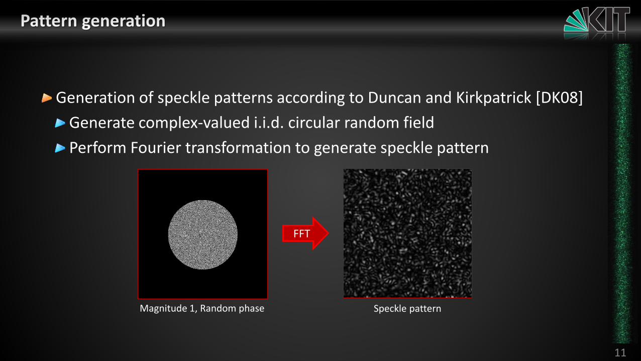
Generation of speckle patterns according to Duncan and Kirkpatrick [DK08]
Generate complex-valued i.i.d. circular random field
Perform Fourier transformation to generate speckle pattern
11
FFT
Magnitude 1, Random phase Speckle pattern

Multiple pattern slices with gradually changing correlation
During access
Select slices and interpolate pattern value (Trilinear filtering)
Generation
Translate circular mask in random field
Generate circular correlation
12
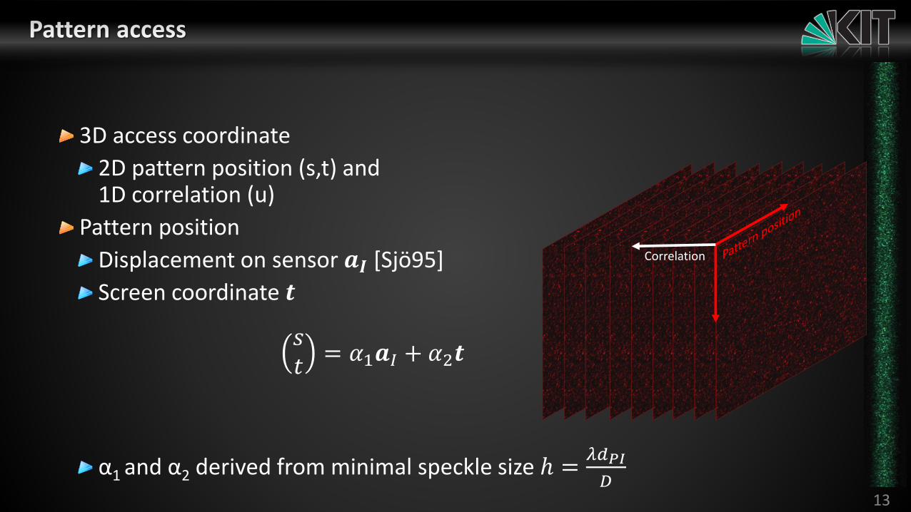
3D access coordinate
2D pattern position (s,t) and1D correlation (u)
Pattern position
Displacement on sensor 𝒂𝑰 [Sjö95]
Screen coordinate 𝒕
𝑠𝑡
= 𝛼1𝒂𝐼 + 𝛼2𝒕
α1 and α2 derived from minimal speckle size ℎ =𝜆𝑑𝑃𝐼
𝐷13
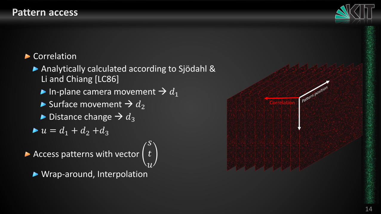
Correlation
Correlation
Analytically calculated according to Sjödahl & Li and Chiang [LC86]
In-plane camera movement 𝑑1Surface movement 𝑑2Distance change 𝑑3
𝑢 = 𝑑1 + 𝑑2 +𝑑3
Access patterns with vector 𝑠𝑡𝑢
Wrap-around, Interpolation
14
Correlation

15
Captured speckles
Rendered speckles

Reproduce limited focussing and speckle effects
Small changes in renderer & small performance impact
Also usable in real-time context (access patterns in pixel shader)
Limitations
No real 3d pattern generated
Constraints in displacement scenarios (e.g. no out-of-focus speckles)
Acknowledgements
Work funded by DFG grant DA 1200/3-1.
16

17
[CHB*12] Cuypers T., Haber T., Bekaert P., Oh S. B., Raskar R. „Reflectance model for diffraction“ ACM Transactions on Graphics 31, 5 (2012), 1–11.[DHH94] Rainer G. Dorsch, Gerd Häusler, and Jürgen M. Herrmann, "Laser triangulation: fundamental uncertainty in distance measurement," Appl. Opt. 33, 1306-1314 (1994)[DK08] Duncan, D., & Kirkpatrick, S. Algorithms for simulation of speckle (laser and otherwise). Proceedings of the SPIE, 6855(January), 685505–685505–8. (2008)[Goo75] Goodman, J.W. “Statistical Properties of Laser Speckle Patterns” in Dainty et al. “Speckle patterns and Related Phenomena”, Topics in Applied Physics, Volume 9, 1975[Hec16] Hecht, E. “Optics (5th edition)”, Pearson (2016)[LA06] Lindsay C., Agu E. “Physically-based real-time diffraction using spherical harmonics” In Proc. of the Second International Conference on Advances in Visual Computing - Volume Part I (2006), ISVC’06, Springer-Verlag, pp. 505–517.[LC86] Li D. W., Chiang F. P. “Decorrelation Functions in Laser Speckle Photography. Journal of the Optical Society of America Optics Image Science and Vision 3, 7 (1986), 1023–1031.[Sjö95] Sjödahl M. “Calculation of speckle displacement, decorrelation, and object-point location in imaging systems” Applied optics 34 (1995), 7998–8010.
18