St. Cloud State UniversitytheRepository at St. Cloud StateCulminating Projects in Computer Science andInformation Technology
Department of Computer Science and InformationTechnology
5-2018
Parallel Implementation of AES using XTS Modeof OperationMuna ShresthaSt. Cloud State University, [email protected]
Follow this and additional works at: https://repository.stcloudstate.edu/csit_etds
Part of the Computer Sciences Commons
This Starred Paper is brought to you for free and open access by the Department of Computer Science and Information Technology at theRepository atSt. Cloud State. It has been accepted for inclusion in Culminating Projects in Computer Science and Information Technology by an authorizedadministrator of theRepository at St. Cloud State. For more information, please contact [email protected].
Recommended CitationShrestha, Muna, "Parallel Implementation of AES using XTS Mode of Operation" (2018). Culminating Projects in Computer Science andInformation Technology. 21.https://repository.stcloudstate.edu/csit_etds/21
Parallel Implementation of AES Using XTS Mode of Operation
by
Muna Shrestha
A Starred Paper
Submitted to the Graduate Faculty of
St. Cloud State University
in Partial Fulfillment of the Requirements
for the Degree
Master of Science
in Computer Science
May, 2018
Starred Paper Committee:
Andrew A. Anda
Jie H. Meichsner
Mehdi Mekni
2
Abstract
Data encryption is essential for protecting data from unauthorized access. The Advanced
Encryption Standard (AES), among many encryption algorithms, is the most popular algorithm
currently employed to secure static and dynamic data. There are several modes of AES
operation. Each of these modes defines a unique way to perform data encryption. XTS mode is
the latest mode developed to protect data stored in hard-disk-like sector-based storage devices.
A recent increase in the rate of data breaches has triggered the necessity to encrypt stored
data as well. AES encryption, however, is a complex process. As it involves a lot of
computations, encrypting huge amount of data would undoubtedly be computationally intensive.
Parallel computers have been used mostly in high-performance computation research to solve
computationally intensive problems. Parallel systems are currently gaining popularity configured
as general purpose multi-core system, even at a desktop level. Several programming models have
been developed to assist the writing of parallel programs, and some have already been used to
parallelize AES. As a result, AES data encryption has become more efficient and applicable.
The message passing model is a popular parallel communication/synchronization model
with an early origin. Message Passing Interface (MPI) is the first standardized, vendor-
independent, message passing library interface that establishes a portable, efficient, and flexible
standard for message passing during computation. Therefore, this paper describes an
implementation of AES using XTS mode in parallel via MPI.
3
Table of Contents
Page
List of Tables ........................................................................................................................ 6
List of Figures ....................................................................................................................... 7
Chapter
1. Introduction ............................................................................................................... 8
2. Parallel Programming with MPI ............................................................................... 12
2.1 Parallel Computer .............................................................................................. 12
2.2 Design of a Parallel Program ............................................................................. 13
2.2.1 Stage 1–Partitioning ............................................................................... 13
2.2.2 Stage 2–Communication ........................................................................ 14
2.2.3 Stage 3–Agglomeration .......................................................................... 15
2.2.4 Stage 4–Mapping .................................................................................... 15
2.3 Implementation of a Parallel Program ............................................................... 16
2.3.1 Parallel Programming Model ................................................................. 17
2.3.2 Writing a Parallel Program Using MPI .................................................. 18
2.4 Communication in MPI Programming ...................................................................... 21
2.4.1 Barrier ..................................................................................................... 23
2.4.2 Broadcast ................................................................................................ 23
2.4.3 Gather ..................................................................................................... 23
2.4.4 Scatter ..................................................................................................... 23
2.4.5 All-to-All ................................................................................................ 24

4
Chapter Page
2.4.6 Reduce .................................................................................................... 24
2.4.7 Prefix ...................................................................................................... 24
3. AES and XTS Mode of Operation ............................................................................ 25
3.1 Background ....................................................................................................... 25
3.2 XTS Mode of Operation .................................................................................... 26
3.2.1 AES using XTS Mode of Operation (XTS-AES) .................................. 27
3.2.2 Ciphertext Stealing ................................................................................. 30
3.3 Advanced Encryption Standard (AES) .............................................................. 31
3.3.1 Substitute Bytes ...................................................................................... 33
3.3.2 Shift Rows .............................................................................................. 35
3.3.3 Mix Columns .......................................................................................... 35
3.3.4 Add Round Key ...................................................................................... 36
3.4 Key Expansion .................................................................................................. 36
3.5 Multiplication in Galios Field (GF92 n)) ........................................................... 38
4. Methodology ............................................................................................................. 40
4.1 Design of Parallel XTS-AES Algorithm ........................................................... 40
4.2 Implementation of Parallel XTS-AES Algorithm ............................................. 45
4.2.1 Task Mapping ......................................................................................... 45
4.2.2 Key Expansion ....................................................................................... 46
4.2.3 Input Data Processing ............................................................................. 47
4.2.4 Single Block Operation .......................................................................... 48

5
Chapter Page
4.2.5 AES Encryption ...................................................................................... 49
4.2.6 Substitute Bytes ...................................................................................... 49
4.2.7 Shift Rows .............................................................................................. 49
4.2.8 Mix Columns .......................................................................................... 50
4.2.9 Add Round Keys .................................................................................... 50
4.2.10 Ciphertext Stealing ................................................................................ 50
4.2.11 Multiplication in GF(2128) ..................................................................... 51
4.2.12 Handle Result ........................................................................................ 51
4.2.13 Synchronize Processors ......................................................................... 51
5. Result and Analysis ................................................................................................... 52
6. Conclusion ................................................................................................................ 57
References ............................................................................................................................ 59
Appendix ............................................................................................................................ 61

6
List of Tables
Table Page
1. Block Cipher Modes of Operation ............................................................................ 26
2. XTS-AES Mode ........................................................................................................ 31
3. AES S-box ................................................................................................................ 33
4. AES Inverse S-box .................................................................................................... 34
5. Values of Nr and Nk ................................................................................................... 37
6. Execution Time (in milliseconds) for n Bytes Data Using p Processors .................. 52
7. Speedup of XTS-AES Algorithm for n Bytes Data Using p Processors .................. 53
8. Efficiency as a Function of n Bytes Input Data on p Processing Elements .............. 56

7
List of Figures
Figure Page
1. Parallel Hello World Program using MPI .............................................................. 19
2. General Structure of a Program Written using MPI .............................................. 21
3(a). XTS-AES Encryption of Single Block .................................................................. 27
3(b). XTS-AES Description on Single Block ................................................................. 28
4. XIS-AES Mode with Ciphertext Stealing .............................................................. 30
5. AES Encryption and Decryption ........................................................................... 32
6. Substitute Byte Transformation ............................................................................. 34
7. Shift Row Transformation ..................................................................................... 35
8. Mix Column Transformation ................................................................................. 35
9. Inverse Mix Column Transformation .................................................................... 36
10. Key Expansion Algorithm ..................................................................................... 37
11. SPMD Program Execution ..................................................................................... 42
12(a). Flowchart of Parallel XTS-AES Encryption Algorithm ........................................ 43
12(b). Flowchart of XTS-AES Single Block Encryption ................................................. 44
12(c). Flowchart of Ciphertext Stealing ........................................................................... 44
13. Variation of Efficiency as the Number of Processing Elements is
Increased for 256000-byet Data ..................................................................... 55
14. Variation of Efficiency as the Problem Size is Increased for Four55
Processing Elements ....................................................................................... 55

8
Chapter 1: Introduction
Data breaches were in the news headline last year. The Equifax data breach, discovered
on July 29, 2017, exploited a website application vulnerability and gained access to certain files.
According to the company's' public customer notice of data breach [1], credit card numbers for
approximately 209,000 consumers, and certain dispute documents containing personal
identifying information for approximately 182,000 consumers, were accessed along with names,
social security numbers, birth dates, addresses, and some driver's license numbers. Following
that, a print edition, published by The Wall Street Journal on September 18, 2017 [2], stated that
more than 11.5 million people had signed up for credit-monitoring offered by Equifax, others
had frozen their credit reports with Equifax and its rival companies such as TransUnion and
Experian PLC. Moreover, its investors shrunk its stock-market value by about $6 billion, or more
than a third, in 10 days, leaving the company crippled. According to a report prepared by
Gemalto [3], there were 918 data breaches worldwide during the first half of 2017. It was a 13%
increase from the last 6 months of 2016. Equifax, and many other companies, have suffered from
such breaches due to the exposure of their data for as little as split second of time. Data security
continues to be challenging as more systems, devices, and other objects become interconnected
with the growth of the Internet of Things [3].
Less than 5% of all breaches investigated by Gemalto involved encrypted data. Still,
many organizations fall short when it comes to data encryption effort. Data breaches take place
not only when data is in transit. Data at rest are likely to be breached equally. Exposure of data at
rest is equivalent to the exposure of data in transit but for an infinite amount of time. Therefore,
as it is undeniable that encryption can actually prevent such breaches, it should be considered as

9
a necessity rather than just an option. With encryption, data is protected even if infrastructure
protections such as firewalls or network access control systems are compromised. Data
confidentiality is obtained by converting input plaintext data into ciphertext. With so many
potential threats to sensitive data from both inside and outside companies, encrypting is the best
way to protect data on personal laptops, storage servers and other devices in addition to emails
and communications. Therefore, stored data encryption is the focus of this paper.
Various symmetric algorithms such as AES, Data Encryption Standard (DES), Rivest
Cipher 4 (RC4) and Blowfish have been developed to encrypt stored data. These algorithms are
similar to each other as all of them use a single key to encrypt data. But they are different in
respect to the length of data they process at a time. For example, AES encrypts data in a 128-bit
sized block and RC4 encrypts data one bit at a time. However, according to William Stallings
[4], AES is comparatively more secure and is currently the most widely used encryption
algorithm. As mentioned in Section 3.1, AES can be operated in various modes. XTS is the
newest block cipher mode approved by the National Institute of Science and Technology (NIST)
in 2010.
With the current trend of recurring data breaches, it is important to encrypt as much data
as possible. As encrypting data is itself a complex process, encrypting huge amount of data is
also computationally intensive. Solving such computationally intensive problems is always time-
consuming. However, advancements in microprocessor technology have yielded more advanced
parallel computing systems. Termed parallel computers, these systems have been employed in
high-performance computation research to solve computationally intensive problems, and they
are now gaining popularity for general purpose computation, even at a desktop level [5].
10
Using parallel computers for solving most problems is fairly uncommon. The increased
availability of parallel computing systems has accelerated interest in exploring the field of
parallel programming. The paper, "Parallelizing AES on multicores and GPUs" [6], shows that
encrypting data using parallel computers results in speedup factors between 2 and 3. This
indicates that data encryption will become more efficient and beneficial if performed in such
parallel systems.
Parallel programming is a term used to define the practice of writing a computer
program that runs with multiple concurrent execution paths. It is similar to writing a serial
program as both involve sequence of steps that tell the computer how to solve a problem. But,
unlike serial programming, parallel programming involves multiple processors working together.
Therefore, in order to benefit from parallel programming, concurrency within the problem needs
to be properly identified and exposed before writing a program.
Section 2.3.1 describes several parallel programming models that have been developed to
assist in writing parallel programs. Some of those models have already been used to parallelize
AES. However, the decision about which model to use to write a parallel program is usually a
combination of a number of factors including the resources available and the nature of the
application being developed.
As AES operating in XTS mode can process data blocks independently, it can be
implemented in parallel [4]. This being the motivation behind doing this project, a parallel
implementation of AES in XTS mode has been performed using message passing model. Parallel
programming using MPI is described in detail in Chapter 2. In Chapter 3, AES and its XTS mode
are explored, followed by the methodology in Chapter 4 which details on how AES has been
11
implemented to run on a parallel computer using MPI. In Chapter 5, results obtained from
parallel implementation are analyzed and compared against results from its serial
implementation. Also, we verify the correctness of the implementation by decrypting its output
ciphertexts and comparing the resulting plaintexts with the initial input plaintexts. The source
code of both parallel and serial implementations of XTS-AES encryption have been listed as
XTS_AES_Encrypt.c and XTS_AES_Serial.c in Appendix A and Appendix C
respectively along with the source code of the parallel implementation of XTS-AES decryption
as XTS_AES_Decrypt.c. Finally, in Chapter 6, we conclude with our insights.

12
Chapter 2: Parallel Programming with MPI
Advancements in computer hardware systems, in terms of their memory and processing
power, have redefined ways of solving problems using computers. There are newer ways of
using computers to make computations more efficient. Programs written using a parallel
programming approach are called parallel programs, and they tend to perform better than
traditional serial programs. This chapter briefly describes parallel computers first, and then
explains how parallel programs are designed and implemented using MPI.
2.1 Parallel Computer
In past, the performance of a computing system had relied on its hardware architecture
and had widely been evaluated in terms of its clock speed. Usually expressed in Megahertz
(MHz) or Gigahertz (GHz), clock speed basically represents the rate at which a system can
complete a processing cycle and depends upon the number of available computing units inside
the system. In 1965, Gordon Moore predicted doubling of the number of transistors on
microprocessors every 18 to 24 months and following that, computer clock speed doubled
roughly every year for more than 40 years. But, in 2005, Gordon Moore himself said his law
cannot continue forever because of an increase in heat generation and circuit power requirements
[7]. Therefore, performance achievable by increasing clock speed maxed out. Parallel
computation was introduced to allow processors to perform better while generating less heat.
These parallel computers are commonly available as a multicore processor or group of single
processors connected via network or hybrid of both.
Processors in a parallel computer generally execute the same or different program
instruction simultaneously on the same or different data. Unlike a serial computer, this type of

13
machine provides multiple execution paths for instructions. Each processor can have its own
local memory or share same memory resources or a mix of both. Among multiple ways of
classifying parallel computers, Flynn's Taxonomy is the most popular. According to M. J. Flynn
[8], such computers are characterized based upon the maximum number of simultaneous
instructions or data being in the same phase of execution. Single Instruction Single Data (SISD),
Multiple Instruction Single Data (MIMD), Single Instruction Multiple Data (SIMD) and Multiple
Instruction Multiple Data (MIMD) are Flynn’s four classification categories, and a parallel
computer can belong to any of them.
2.2 Design of a Parallel Program
An algorithm is a set of well-defined steps that lead to the solution of a problem in finite
time. Algorithms are essential for solving problems using computers. As in serial programming,
parallel programming includes an algorithm design phase that generates a parallel algorithm. A
parallel algorithm defines steps to solve a problem using multiple processors. Therefore, in
addition to just specifying steps, designing a parallel algorithm requires identifying and exposing
concurrency within the problem. Ian Foster [9], has presented a methodological approach for
creating a parallel algorithm and it has four distinct stages:
2.2.1 Stage 1–Partitioning
In this stage, the main problem is divided into smaller computation units to expose
opportunities for its parallel execution. Such smaller units are called tasks and are created using
either domain decomposition or functional decomposition [9].

14
2.2.1.1 Domain Decomposition: In this approach, data associated with the problem is divided
into small partitions of nearly equal size. This decomposed data may be an input to the program,
an output of the program, or intermediate values maintained by the program.
2.2.1.2 Functional Decomposition: In this alternative approach, the computation to be
performed is decomposed before decomposing data used by it. After successfully dividing the
computation into disjoint tasks, data requirements of tasks are examined. In case of disjoint data
requirements, partitioning is complete, otherwise if data overlap is present, significant
communication is required to avoid less desirable data replication.
2.2.2 Stage 2–Communication
Tasks created in an initial partitioning stage are expected to execute concurrently and
independently from each other. However, computations performed by a task may require data
associated with another task. In this case, communication between tasks is necessary to proceed
the computation further. In this stage, such communication requirements are identified and
respective communication operations are introduced to satisfy all requirements. In general, such
communication patterns are categorized along four loosely orthogonal axes: local/global,
structured/unstructured, static/dynamic and synchronous/asynchronous [9].
In local communication, a small set of tasks communicate with each other. Each task
communicates with few other tasks only. In contrast, global communication takes place between
many tasks. Each task communicates with a comparatively larger number of other tasks.
In structured communication, a group of communicating tasks forms regular structure,
such as a tree or grid. This structure does not change over time. Whereas, unstructured
communication networks could be an arbitrary graph whose structure might change over time.
15
In static communication, identities of communicating tasks do not change over time. In
contrast, the identity of each task may be determined at runtime in dynamic communication,
making it highly variable.
In synchronous communication, tasks execute in a coordinated fashion. Communicating
tasks cooperate in data transfer operations. Whereas, in an asynchronous communication, tasks
may randomly obtain data without cooperating.
2.2.3 Stage 3–Agglomeration
The first two stages of the parallel algorithm design process help in identifying a set of
tasks and possible communications between them [9]. However, the design needs to be
specialized for an efficient execution on any particular parallel computer as there may be more
tasks than available processors. Also, the parallel computer itself may not be suitable for efficient
execution of small tasks. Therefore, in this stage, tasks identified in partitioning stage are
grouped together if possible.
2.2.4 Stage 4–Mapping
In this stage, tasks are mapped to processors such that processors are utilized with less
idling and communication costs [9]. Unlike in uniprocessors or shared-memory processors where
operating systems and hardware mechanisms are present to map executable tasks to available
processors, in other types of processors, general-purpose mapping is done explicitly. Listed
below are two basic mapping strategies to minimize total execution time of a parallel program.
➢ Place concurrently executable tasks on different processors in order to enhance
concurrency.
16
➢ Place frequently communicating tasks on the same processor in order to enhance
locality.
Mapping can be performed statically, before execution, or dynamically at runtime. Tasks
created using domain decomposition are easy to map when they are equal sized and require
structured local and/or global communication only. In this case, the mapping is subsumed into
the agglomeration phase. This results in a Single Program Multiple Data (SPMD) program which
has exactly one task per processor and minimum interprocess communication.
In case of domain decomposition resulting in unequal sized tasks and/or unstructured
communication patterns, load balancing algorithms are used. These algorithms identify efficient
agglomeration and mapping strategies by using heuristic techniques typically. Whereas, for most
complex problems in which either total number of tasks or the total amount of computation or
communication keeps changing dynamically, dynamic load balancing algorithm is used. This
algorithm is mostly executed locally as it is used periodically to determine a new agglomeration
and mapping.
Tasks created using functional decomposition usually have shorter execution times and
they communicate with other tasks only at the beginning and end of execution. Such tasks are
mapped to idle, or almost idle, processors during runtime using task-scheduling algorithms.
2.3 Implementation of a Parallel Program
Different programming languages and libraries have been developed to write explicitly
parallel programs. Also, numerous programming models are available. Each of these models
presents a unique way to write parallel programs using available programming languages and
libraries. This section provides more information on such parallel programming models.

17
2.3.1 Parallel Programming Model
A parallel programming model is an abstraction of a computer system that allows
convenient expression of an algorithm and its composition in programs. It is machine
architecture-independent and exists above hardware and memory architectures. Several
programming models have been developed for explicit parallel programming. Each of these
models can be implemented on any underlying hardware architecture [5]. The shared memory
model, threads model, message passing model, data parallel model and hybrid model are some
common parallel programming models.
These models define a unique view of an address space that a machine makes available
for programming, a degree of synchronization imposed on concurrent activities, and a
multiplicity of programs [7]. However, selection of the model to be used is usually a
combination of several factors like the resources available and the nature of the problem.
2.3.1.1 Message Passing Model: Message passing is one of the oldest and most widely used
methodologies for writing parallel programs. It focuses more on solving the problem using
multiple processors rather than targeting the hardware being used. Therefore, it has been used
since early days of parallel processing [7].
The logical view of a machine supporting this model basically contains p processors,
each with its own private address space. The data involved is explicitly partitioned before being
placed inside address spaces. The processor holding the data and the processor that requires the
data cooperate with each other prior to actual data transfer.
Generally, this model supports execution of different programs on each participating
processors. Though this results in flexible programs, it makes the job of writing parallel
18
programs highly unscalable [7]. Therefore most message passing programs are written using
SPMD approach which makes most processors execute identical code.
MPI, a message passing library interface specification, primarily addresses message
passing model [11]. MPI is a de facto standard defined by a community of parallel computing
vendors, computer scientists, and application developers [5].
Before 1992, many parallel computers were based on message passing architectures due
to their lower costs compared to shared-address-space architectures [7]. Message passing was a
natural way of programming for those types of computers. As a result, a variety of vendor-
specific message passing libraries were developed. Most of those libraries suffered from
compatibility failures. They were vendor specific and did not run on parallel computers built by
other vendors. Furthermore, they were mostly syntactically different from each other. Therefore,
the MPI standardization effort began with a workshop on Standards for Message-Passing in
Distributed Memory Environment on 1992 [11].
2.3.2 Writing a Parallel Program Using MPI
As mentioned in Section 2.3.1.1, MPI is basically a library interface and therefore has
multiple implementations. It contains over 125 routines that are used for parallel processing.
Initializing and terminating MPI execution environment, getting information about parallel
computing environment, and sending and receiving messages between processors are some
commonly performed MPI tasks. It has been implemented in more than one way to meet
specific requirements. Among many different types of MPI implementations, Open MPI is an
open source implementation that is freely available. Below is a well-known “Hello world”
program in parallel, written using the C programming language and Open MPI. Compared to
19
conventional serial C language implementation of the “Hello world” program, it includes some
additional MPI statements that are required for writing the parallel program using MPI.
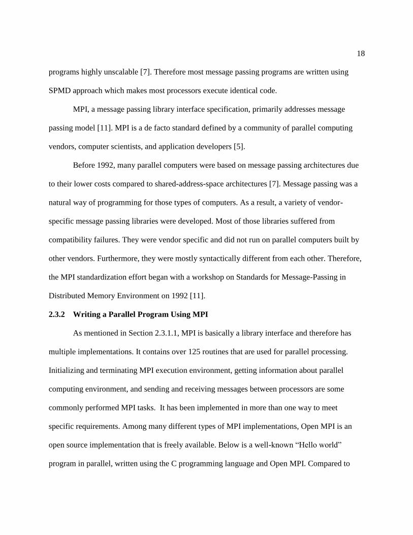
Program: mpihello.c
Figure 1: Parallel Hello World Program using MPI
Including the MPI header file with #include <mpi.h> is the first step in writing any
MPI program. This header file contains MPI function declarations. Then, the MPI environment is
initialized with MPI_Init(&argc, &argv) function. During this initialization, each of
MPI's global and internal variables such as a communicator (an object that defines a collection of
communicating processes) and unique ranks of all processors, get constructed. After
MPI_Init, MPI_Comm_size and MPI_COMM_WORLD are two other main functions that get
called.
MPI_Comm_size returns the size of a communicator which is a total number of
participating processors. MPI_COMM_WORLD encloses all available processors and returns the
total number of processors requested for the job. Each of these processors in the communicator is
assigned an incremental rank starting from zero. These ranks uniquely identify communicating
processors while sending and receiving messages. If required, they are also used conditionally to
20
control an execution of the program. MPI_Comm_rank function returns the rank of a processor
in the communicator. MPI_Finalize is a final routine called to clean up the MPI
environment. After this function, no more MPI calls are allowed to be made.
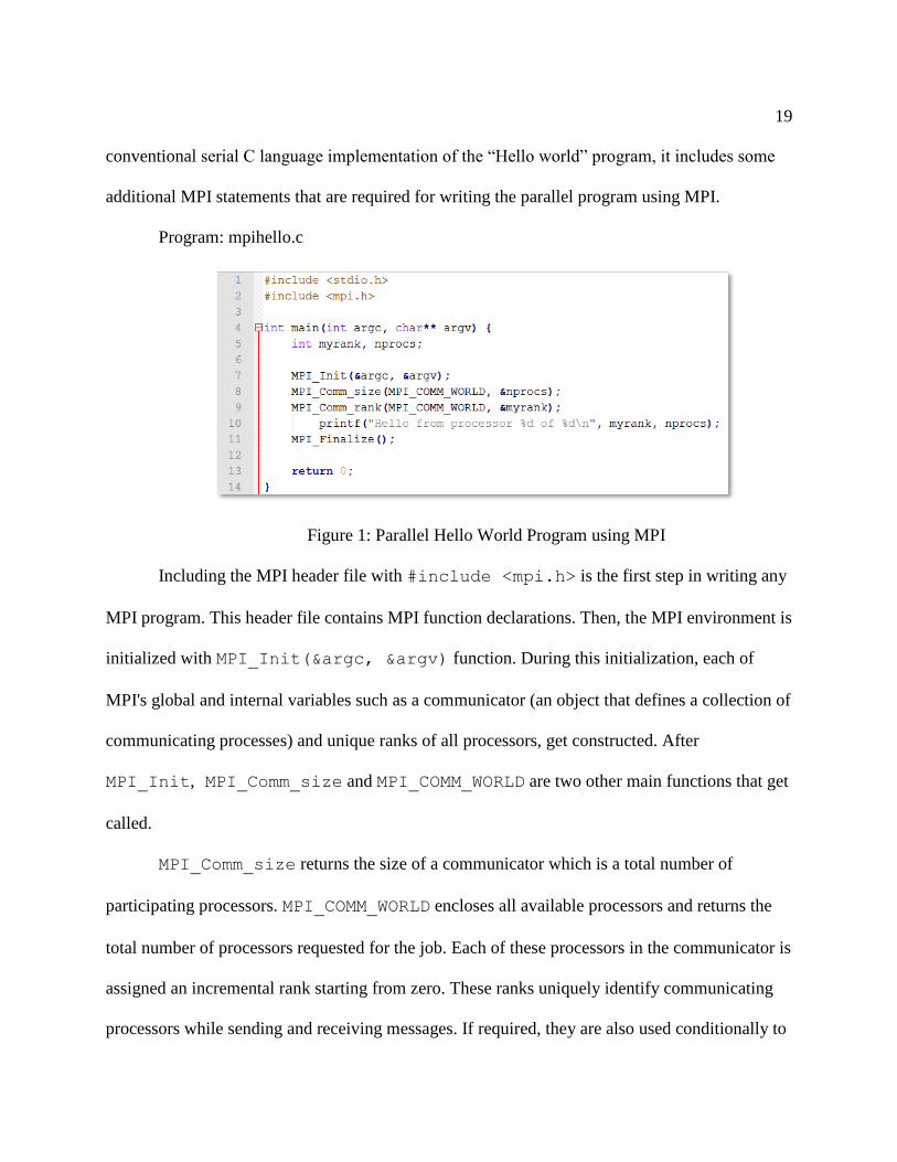
Parallel programs written using MPI are compiled and linked using mpicc. Once the
program is compiled successfully, it is executed using mpiexec. Below is an output of the
mpihello.c program:
Hello from processor 1 of 4
Hello from processor 0 of 4
Hello from processor 3 of 4
Hello from processor 2 of 4
As mentioned earlier, this program was compiled as mpicc mpihello.c –o
mpihello and then executed as mpiexec –n 4 mpihello. Four processors are requested
to print the “Hello world” statement. Depending upon the number of processors available, these
parallel programs can be executed on one or more processors. Given below is a general structure
of all MPI programs.

21
Figure 2: General Structure of a Program Written using MPI [12]
2.4 Communication in MPI Programming
Processors interact by sending and receiving messages in MPI programming [7].
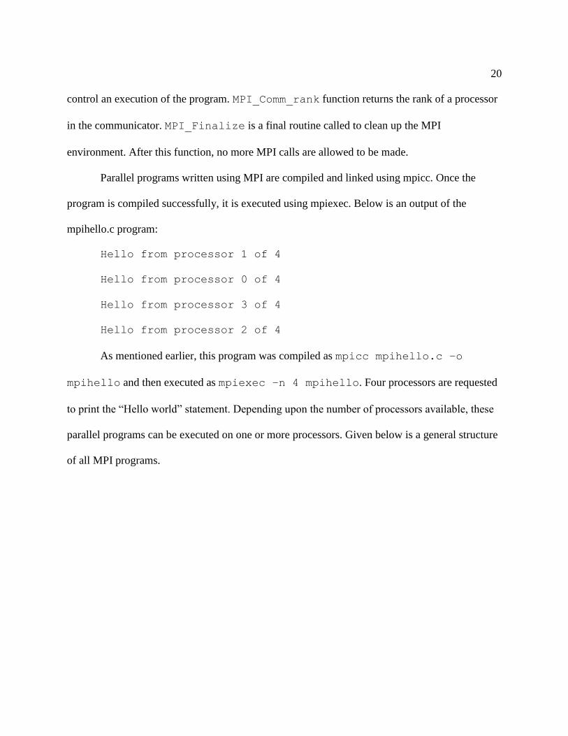
MPI_Send and MPI_Recv are two functions basically used to send and receive messages
between two processors. They are called in the following sequence:
int MPI_Send(void *bufSend, int count, MPI_Datatype
datatype, int dest, int tag, MPI_Comm comm)
22
int MPI_Recv(void *bufRecv, int count, MPI_Datatype
datatype, int source, int tag, MPI_Comm comm, MPI_Status
*status)
MPI_Send sends data stored in a buffer pointed by pointer bufSend. This buffer
contains count number of consecutive entries of the type specified by parameter datatype.
Destination of the message sent by MPI_Send is uniquely specified by the rank of destination
process dest and communicator comm. Additionally, MPI_Send contains an integer-valued
tag that distinguishes messages from one another.
MPI_Recv receives the message sent by a processor whose rank is represented by
source in comm. The tag of the message sent must be that specified by tag parameter in the
MPI_Recv function. In case a processor sends more than one message with an identical tag,
only one message is received and stored in continuous locations in a buffer pointed by
bufRecv. count and datatype arguments of this function are used to specify the length of
the buffer and type of the data it stores. Therefore, the message received should be of type
datatype and length equal to or less than count.
In addition to sending and receiving data between just two processors, MPI allows
collective communication among the group of participating processors. It provides an extensive
set of functions for performing various collective communication operations. Barrier, broadcast,
scatter, gather, reduction, all-to-all, and prefix are some common types of such operations. Each
of these functions contains a communicator as an argument and processors belonging to the
communicator communicate by calling functions containing communicator as one of its
parameters. Short descriptions of each of these operations follow:

23
2.4.1 Barrier
This is a synchronization operation performed in MPI using MPI_Barrier function.
This function call returns only after all processors in the group have called it.
2.4.2 Broadcast
This operation is performed to send data from a processor to all other processors in the
group. It is performed in MPI using MPI_Bcast function as:
int MPI_Bcast(void *buf, int count, MPI_Datatype datatype, int
source, MPI_Comm comm).
2.4.3 Gather
The gather operation is used to collect data from all processors including the one
collecting data. It is performed using the MPI_Gather function as:
int MPI_Gather(void *sendbuf, int sendcount, MPI_Datatype
senddatatype, void *recvbuf, int recvcount, MPI_Datatype
recvdatatype, int target, MPI_Comm comm).
2.4.4 Scatter
This operation is used to send a subset of data to all processors including source itself. It
is performed using the MPI_Scatter function as:
int MPI_Scatter(void *sendbuf, int sendcount, MPI_Datatype
senddatatype, void *recvbuf, int recvcount, MPI_Datatype
recvdatatype, int source, MPI_Comm comm).
24
2.4.5 All-to-All
During this operation, each processor sends a different portion of the data array to other
processors including itself. It is performed using the MPI_Alltoall function as:
int MPI_Alltoall(void *sendbuf, int sendcount, MPI_Datatype
senddatatype, void *recvbuf, int recvcount, MPI_Datatype
recvdatatype, MPI_Comm comm).
2.4.6 Reduce
This operation combines elements stored in the buffer of each processor using an
operation specified by op and returns combined values. It is performed using the MPI_Reduce
function as:
int MPI_Reduce(void *sendbuf, void *recvbuf, int count,
MPI_Datatype datatype, MPI_Op op, int target, MPI_Comm comm).
2.4.7 Prefix
This operation performs a prefix reduction of data stored in the buffer at each processor.
It is performed using the MPI_Scan function as:
int MPI_Scan(void *sendbuf, void *recvbuf, int count,
MPI_Datatype datatype, MPI_Op op, MPI_Comm comm).

25
Chapter 3: AES and XTS Mode of Operation
Data security is an essential part of today’s computer security whether it is securing data
in motion or at rest. Block cipher is one of the commonly used encryption algorithms that
converts b-bit long input block of plaintext into b-bit long block of ciphertext using an
encryption key. AES is a type of block cipher which was selected by the National Institute of
Science and Technology (NIST) as the most secure encryption algorithm in 2001 [9]. This
chapter provides details on AES and its operation in XTS mode.
3.1 Background
Encryption is an important technique to secure data. As it protects data even when
infrastructure protection such as firewalls or network access control systems get compromised, it
is important to be performed using a secure standard like AES. In case of data longer than b-bit,
it gets broken into multiple b-bit long blocks and processed using the same key. According to
William Stallings [4], several security issues arise due to this. Therefore, NIST defined different
modes of operation to apply a block cipher to a sequence of data blocks or data stream in a
variety of applications.
A mode of operation is basically a technique used for enhancing an effect of a
cryptographic algorithm or adapting the algorithm itself for an application. Five different modes
have been defined for AES data encryption. These modes are Electronic Codebook (ECB),
Cipher Block Chaining (CBC), Cipher Feedback (CFB), Output Feedback (OFB) and Counter
(CTR). They are summarized in Table 1.

26
Table 1: Block Cipher Modes of Operation [4]
XTS is a newer mode introduced by IEEE Security in Storage Working Group (SISWG)
to encrypt data stored in hard-disk-like sector-based storage devices [9].
3.2 XTS Mode of Operation
XTS is a XEX encryption mode with tweak and ciphertext stealing feature [9]. It is a
tweakable mode developed as an alternative to LRW mode proposed by SISWG as the most
promising mode in its early drafts. Unlike CBC mode that has been in use for many years, XTS
has complete support for parallelism in its structure. A block cipher in this mode consists of three
inputs: a plaintext (P) to be encrypted, a symmetric key (K), and a tweak (T). An output from the
encryption (E) is a ciphertext (C) represented as E (K, T, P). Likewise, decryption (D) of a
ciphertext (C) results in plaintext (P) represented as D (K, T, C). Here, in both encryption and
27
decryption, while key provides security, tweak provides variability, i.e., encrypting a plaintext
using the same key but different tweaks result in different ciphertexts and decrypting a ciphertext
using the same key but different tweaks result in different plaintexts.
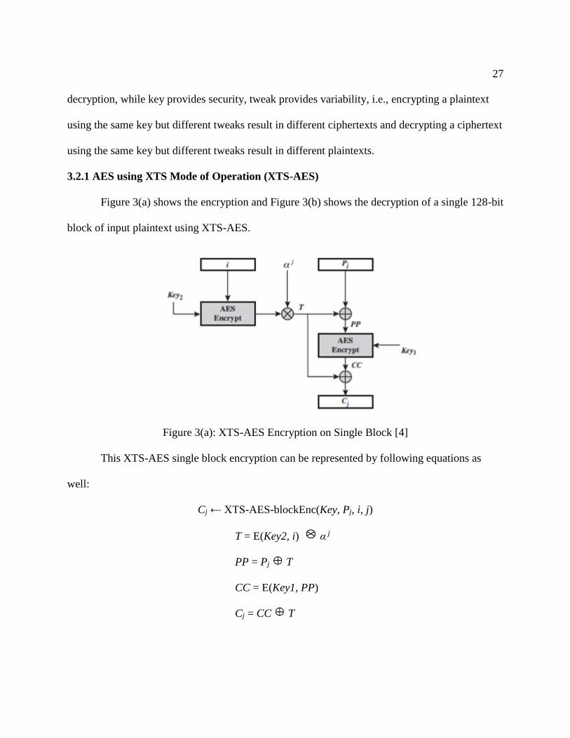
3.2.1 AES using XTS Mode of Operation (XTS-AES)
Figure 3(a) shows the encryption and Figure 3(b) shows the decryption of a single 128-bit
block of input plaintext using XTS-AES.
Figure 3(a): XTS-AES Encryption on Single Block [4]
This XTS-AES single block encryption can be represented by following equations as
well:
Cj ← XTS-AES-blockEnc(Key, Pj, i, j)
T = E(Key2, i) α j
PP = Pj T
CC = E(Key1, PP)
Cj = CC T

28
Figure 3(b): XTS-AES Decryption on Single Block [4]
This XTS-AES single block decryption can be represented by following equations as
well:
Pj← XTS-AES-blockDec(Key, Cj, i, j)
T = E(Key2, i) α j
CC = Cj T
PP = D(Key1, CC)
Pj = PP T
where:
XTS-AES-blockEnc = Single block encryption.
XTS-AES-blockDec = Single block decryption.
Key = The 256 or 512-bit XTS-AES key, parsed as a concatenation of two fields of equal size
called Key1 and Key2, such that Key = Key1 || Key2.
Pj = The jth block of 128-bit of plaintext.
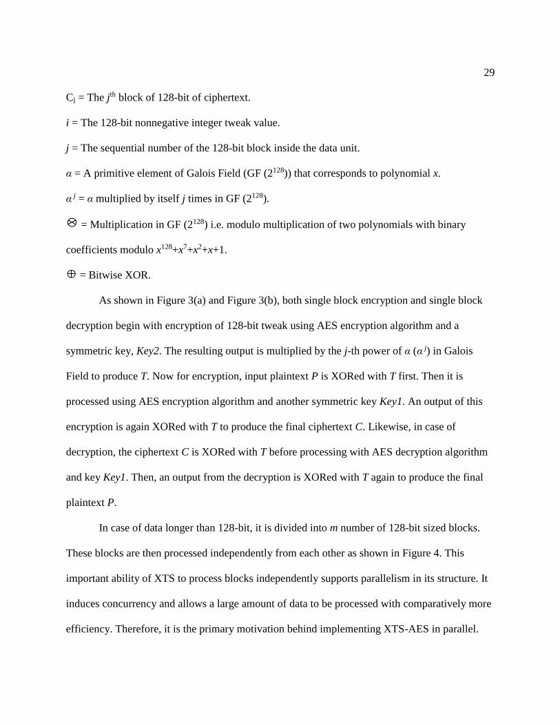
29
Cj = The jth block of 128-bit of ciphertext.
i = The 128-bit nonnegative integer tweak value.
j = The sequential number of the 128-bit block inside the data unit.
α = A primitive element of Galois Field (GF (2128)) that corresponds to polynomial x.
α j = α multiplied by itself j times in GF (2128).
= Multiplication in GF (2128) i.e. modulo multiplication of two polynomials with binary
coefficients modulo x128+x7+x2+x+1.
= Bitwise XOR.
As shown in Figure 3(a) and Figure 3(b), both single block encryption and single block
decryption begin with encryption of 128-bit tweak using AES encryption algorithm and a
symmetric key, Key2. The resulting output is multiplied by the j-th power of α (α j) in Galois
Field to produce T. Now for encryption, input plaintext P is XORed with T first. Then it is
processed using AES encryption algorithm and another symmetric key Key1. An output of this
encryption is again XORed with T to produce the final ciphertext C. Likewise, in case of
decryption, the ciphertext C is XORed with T before processing with AES decryption algorithm
and key Key1. Then, an output from the decryption is XORed with T again to produce the final
plaintext P.
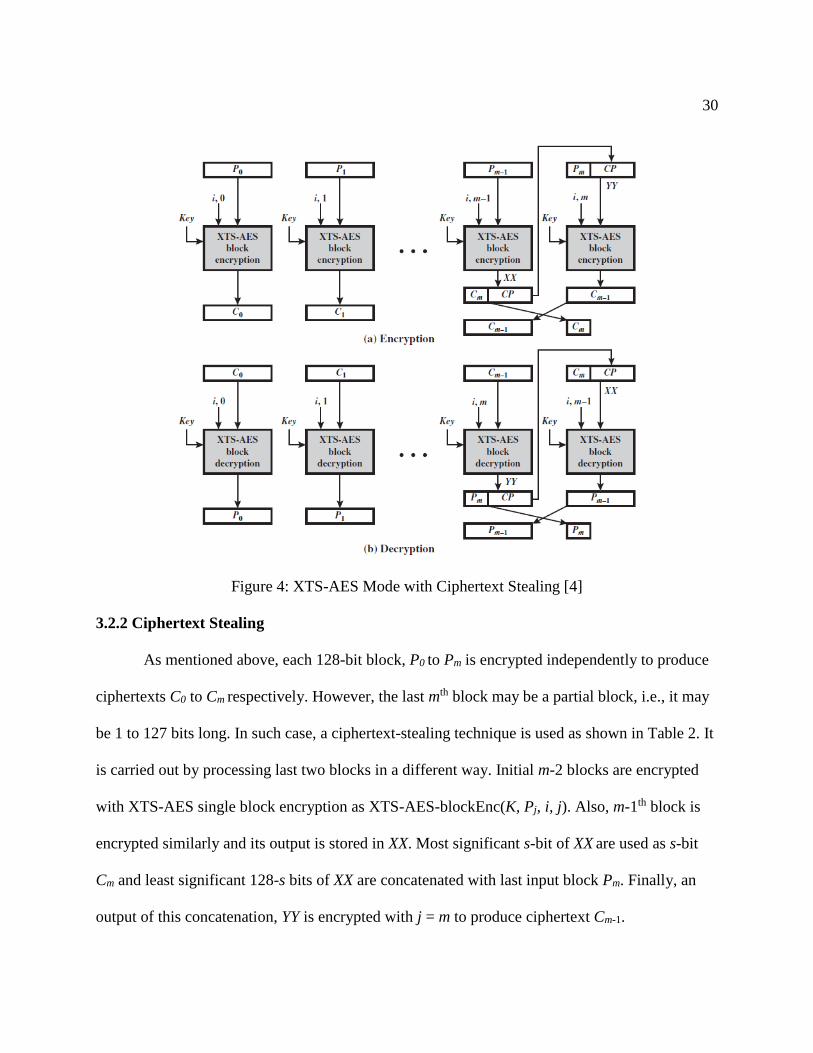
In case of data longer than 128-bit, it is divided into m number of 128-bit sized blocks.
These blocks are then processed independently from each other as shown in Figure 4. This
important ability of XTS to process blocks independently supports parallelism in its structure. It
induces concurrency and allows a large amount of data to be processed with comparatively more
efficiency. Therefore, it is the primary motivation behind implementing XTS-AES in parallel.
30
Figure 4: XTS-AES Mode with Ciphertext Stealing [4]
3.2.2 Ciphertext Stealing
As mentioned above, each 128-bit block, P0 to Pm is encrypted independently to produce
ciphertexts C0 to Cm respectively. However, the last mth block may be a partial block, i.e., it may
be 1 to 127 bits long. In such case, a ciphertext-stealing technique is used as shown in Table 2. It
is carried out by processing last two blocks in a different way. Initial m-2 blocks are encrypted
with XTS-AES single block encryption as XTS-AES-blockEnc(K, Pj, i, j). Also, m-1th block is
encrypted similarly and its output is stored in XX. Most significant s-bit of XX are used as s-bit
Cm and least significant 128-s bits of XX are concatenated with last input block Pm. Finally, an
output of this concatenation, YY is encrypted with j = m to produce ciphertext Cm-1.

31
This ciphertext stealing technique is also applied to recover plaintext Pm from s-bit
ciphertext Cm. For that, C0 to Cm-2 are decrypted using a single block XTS-AES decryption
(XTS-AES-blockDec(K, Cj, i, j)) initially. Likewise, m-1th ciphertext is decrypted to produce YY.
Then most significant s-bit of YY are used as s-bit Pm and least significant 128-s bits of YY are
concatenated with last ciphertext block Cm. Finally, an output of this concatenation, XX, is
decrypted with j = m to produce plaintext Pm-1.
Table 2: XTS-AES Mode [4]
3.3 Advanced Encryption Standard (AES)
As mentioned in Section 3.2, AES algorithm intakes 128-bit block of data to perform
encryption or decryption and a key in both cases. Initially, a 128-bit block of input plaintext is
represented as a 4 × 4 square matrix of bytes. Then it is copied into a state array and processed as
a single matrix on each processing round. After last round, the state array is copied into an output
matrix.

32
AES uses either 16, or 24, or 32-byte (128, 192, or 256-bit) of a symmetric key.
Depending upon the length of the key, it is also referred to as AES-128, AES-192, or AES-256
and it contains 10, 12, or 14 processing rounds respectively. Except for the final Nth round, all
other N-1 rounds consist of four different stages to perform bytes substitution, shift rows, mix
columns and add round keys. The final round doesn’t consist mix columns stage whereas there is
just add round key stage in Round 0 before the first round. Figure 5 shows AES encryption and
decryption in N rounds including Round 0.
Figure 5: AES Encryption and Decryption [4]
33
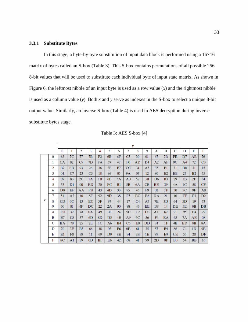
3.3.1 Substitute Bytes
In this stage, a byte-by-byte substitution of input data block is performed using a 16×16
matrix of bytes called an S-box (Table 3). This S-box contains permutations of all possible 256
8-bit values that will be used to substitute each individual byte of input state matrix. As shown in
Figure 6, the leftmost nibble of an input byte is used as a row value (x) and the rightmost nibble
is used as a column value (y). Both x and y serve as indexes in the S-box to select a unique 8-bit
output value. Similarly, an inverse S-box (Table 4) is used in AES decryption during inverse
substitute bytes stage.
Table 3: AES S-box [4]

34
Table 4: AES Inverse S-box [4]
Figure 6: Substitute Byte Transformation [4]
35
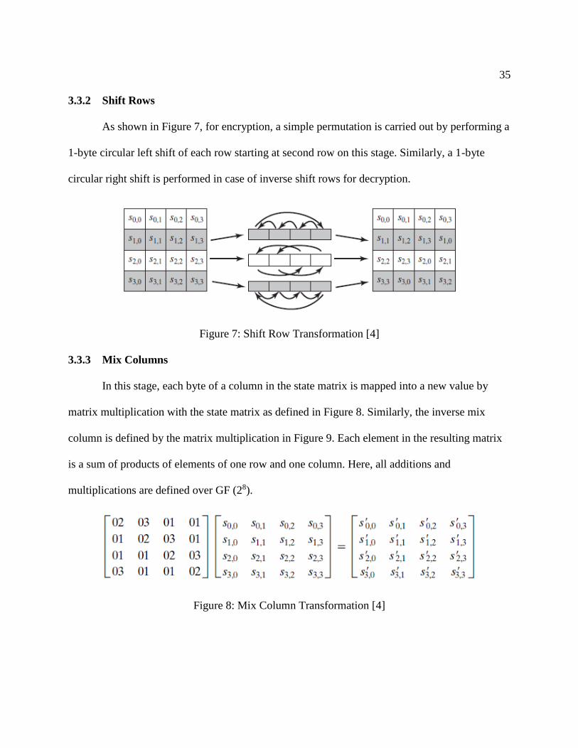
3.3.2 Shift Rows
As shown in Figure 7, for encryption, a simple permutation is carried out by performing a
1-byte circular left shift of each row starting at second row on this stage. Similarly, a 1-byte
circular right shift is performed in case of inverse shift rows for decryption.
Figure 7: Shift Row Transformation [4]
3.3.3 Mix Columns
In this stage, each byte of a column in the state matrix is mapped into a new value by
matrix multiplication with the state matrix as defined in Figure 8. Similarly, the inverse mix
column is defined by the matrix multiplication in Figure 9. Each element in the resulting matrix
is a sum of products of elements of one row and one column. Here, all additions and
multiplications are defined over GF (28).
Figure 8: Mix Column Transformation [4]
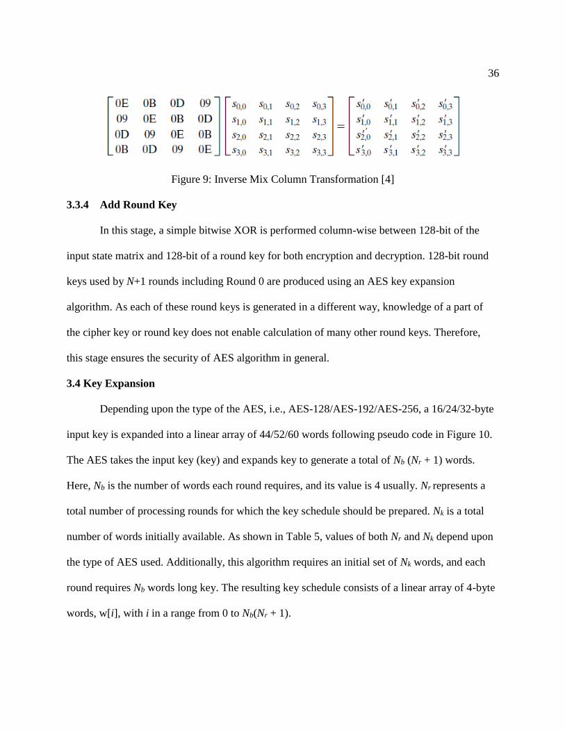
36
Figure 9: Inverse Mix Column Transformation [4]
3.3.4 Add Round Key
In this stage, a simple bitwise XOR is performed column-wise between 128-bit of the
input state matrix and 128-bit of a round key for both encryption and decryption. 128-bit round
keys used by N+1 rounds including Round 0 are produced using an AES key expansion
algorithm. As each of these round keys is generated in a different way, knowledge of a part of
the cipher key or round key does not enable calculation of many other round keys. Therefore,
this stage ensures the security of AES algorithm in general.
3.4 Key Expansion
Depending upon the type of the AES, i.e., AES-128/AES-192/AES-256, a 16/24/32-byte
input key is expanded into a linear array of 44/52/60 words following pseudo code in Figure 10.
The AES takes the input key (key) and expands key to generate a total of Nb (Nr + 1) words.
Here, Nb is the number of words each round requires, and its value is 4 usually. Nr represents a
total number of processing rounds for which the key schedule should be prepared. Nk is a total
number of words initially available. As shown in Table 5, values of both Nr and Nk depend upon
the type of AES used. Additionally, this algorithm requires an initial set of Nk words, and each
round requires Nb words long key. The resulting key schedule consists of a linear array of 4-byte
words, w[i], with i in a range from 0 to Nb(Nr + 1).

37
Table 5: Values of Nr and Nk
Nr Nk
AES-128 10 4
AES-192 12 6
AES-256 14 8
Figure 10: Key Expansion Algorithm [11]
Expansion of the input key proceeds according to the pseudo code mentioned above. It
can be seen that initial Nk words of an expanded key are filled by dividing the input key into Nk
words. After that, every following word, w[i], is generated by XORing previous word, w[i-1]
38
with Nk positions earlier word, w[i-Nk]. For words in positions that are multiple of Nk, a
transformation is applied to w[i-1]. This transformation consists of a cyclic shift of bytes in w[i-
1] followed by bytes substitution on each byte of its input word using the S-box in Table 3. Then
its output is XORed with a round constant in a round constant word array Rcon[]. Rcon[]
contains values given by [xi-1,{00},{00},{00}] with xi-1 being powers of x ({02}) in the field
GF(28).
3.5 Multiplication in Galois Field (GF(2n))
A field is defined as a set of elements in which addition, subtraction, multiplication, and
division can be performed without leaving the set. Rational numbers, real numbers, and complex
numbers are some examples of fields. Finite fields and infinite fields are basically two types of
field. Finite fields play a crucial role in the context of cryptography. The Galois field (GF (2n)) is
a finite field that consists of 2n elements and is used in XTS-AES for multiplication.
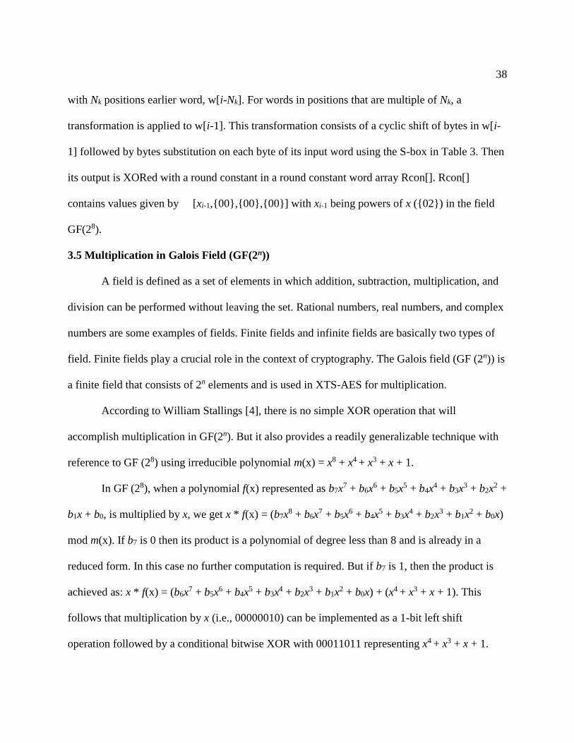
According to William Stallings [4], there is no simple XOR operation that will
accomplish multiplication in GF(2n). But it also provides a readily generalizable technique with
reference to GF (28) using irreducible polynomial m(x) = x8 + x4 + x3 + x + 1.
In GF (28), when a polynomial f(x) represented as b7x7 + b6x
6 + b5x5 + b4x
4 + b3x3 + b2x
2 +
b1x + b0, is multiplied by x, we get x * f(x) = (b7x8 + b6x
7 + b5x6 + b4x
5 + b3x4 + b2x
3 + b1x2 + b0x)
mod m(x). If b7 is 0 then its product is a polynomial of degree less than 8 and is already in a
reduced form. In this case no further computation is required. But if b7 is 1, then the product is
achieved as: x * f(x) = (b6x7 + b5x
6 + b4x5 + b3x
4 + b2x3 + b1x
2 + b0x) + (x4 + x3 + x + 1). This
follows that multiplication by x (i.e., 00000010) can be implemented as a 1-bit left shift
operation followed by a conditional bitwise XOR with 00011011 representing x4 + x3 + x + 1.
39
In summary for GF(28), x * f(x) = (b6b5b4b3b2b1b00) if b7 = 0. Else if b7 = 1, x * f(x) =
(b6b5b4b3b2b1b00) XOR (00011011) and multiplication by a higher power of x can be achieved by
its repeated application.

40
Chapter 4: Methodology
Parallel implementation of AES using XTS mode of operation is a C implementation of
an XTS-AES algorithm which can be executed simultaneously in more than one processor. It has
been implemented to optimize encryption of data stored in hard-disk like storage devices. For
that, a parallel XTS-AES encryption algorithm is designed following the methodological
approach described in Chapter 2 and then implemented in C using message passing parallel
programming model with MPI. This chapter provides details on how both design and
implementation of the parallel XTS-AES algorithm have been carried out in this project.
4.1 Design of Parallel XTS-AES Algorithm
As mentioned in Chapter 1, encryption of stored data lies at the center of this project.
However, in addition to specifying steps to encrypt data, designing a parallel XTS-AES
algorithm includes an additional responsibility of identifying and exposing concurrency. As a
result, creating a parallel XTS-AES algorithm that runs in p number of processors involves
following steps:
Step 1–Partitioning Problem into Concurrent Tasks: In this step, task of encrypting
high amount of data is partitioned into smaller tasks by using data decomposition. Input data is
partitioned into 128-bit long blocks to be encrypted concurrently. Therefore, data blocks
represent most tasks in the parallel XTS-AES algorithm. Additionally, a functional
decomposition is also performed to create few functional tasks such as preprocessing data, key
expansion, encryption, ciphertext stealing, and handling output.
41
Step 2–Managing Communication between Interacting Tasks: The parallel XTS-AES
algorithm is designed to encrypt each 128-bit data block independently. Distributing data among
participating processors involves sending data from a root processor (a processor with rank 0) to
all participating processors including itself. Also functional tasks may need data being processed
by another task. However, the identity of these communicating tasks would stay same throughout
the encryption, and data transfer would take place only at the beginning, while distributing input
data among processors, and at the end while gathering outputs from them. Therefore,
communication is also static and synchronous.
Step 3–Agglomerating Tasks Created from Partitioning: As the size of the data set
being processed would always be large, the total number of tasks created by partitioning the data
would also be greater than the total number of processors available. Tasks resulting from
functional decomposition are also performed on all data. Therefore, the design is customized to
create similar p coarse-grained tasks, one per processor. Each task contains a certain number of
data blocks and pre-defined functional tasks.
Step 4–Mapping Concurrent Tasks onto Processors: As identical tasks would be
created after an agglomeration step and required communication between them is static, global,
and synchronous, mapping tasks to processors is subsumed in the agglomeration stage. Each
processor is assigned exactly one task by using a block distribution of the input array.
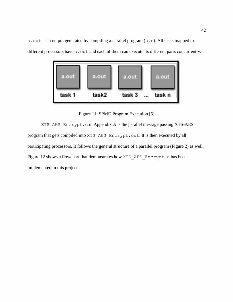
In general, like in most message passing programs, the SPMD approach has been used in
this project to expose concurrency. Basically, in the SPMD approach, all processors have exact
same copy of the program, but they execute different part of it. For example in Figure 11,
42
a.out is an output generated by compiling a parallel program (a.c). All tasks mapped to
different processors have a.out and each of them can execute its different parts concurrently.
Figure 11: SPMD Program Execution [5]
XTS_AES_Encrypt.c in Appendix A is the parallel message passing XTS-AES
program that gets compiled into XTS_AES_Encrypt.out. It is then executed by all
participating processors. It follows the general structure of a parallel program (Figure 2) as well.
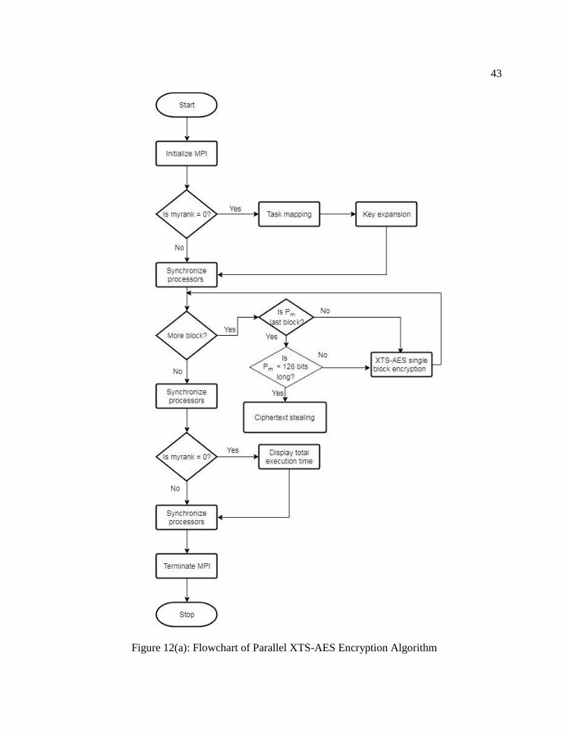
Figure 12 shows a flowchart that demonstrates how XTS_AES_Encrypt.c has been
implemented in this project.
43
Figure 12(a): Flowchart of Parallel XTS-AES Encryption Algorithm

44
Figure 12(b): Flowchart of XTS-AES Single Block Encryption
Figure 12(c): Flowchart of Ciphertext Stealing
45
4.2 Implementation of Parallel XTS-AES Algorithm
As mentioned earlier, XTS_AES_Encrypt.c has been implemented in C using MPI.
Below is an implementation detail of some important operations performed in parallel XTS-
AES.
4.2.1 Task Mapping
A task in parallel XTS-AES is basically a partition of data that needs to be encrypted and
operations performed on it. Mapping tasks to processors generally means distributing data
partitions among participating processors. Practically, XTS-AES is designed to process data
stored in sector-based devices. But in this project data have been stored in a text file
input.txt in hexadecimal format. As all digits in hexadecimal number system (0, 1,….,9, a,
…,f) can be represented in binary using 4-bit, each character from input.txt file is
considered to be just 4-bit long. These characters are read from the input file into an unsigned
character array global_input one byte at a time. Size of the global_input array is
determined at run time from a predefined TOTAL_NUMBER_OF_ITEMS constant. Total number
of characters in input.txt file is manually stored in TOTAL_NUMBER_OF_ITEMS before
compiling the program.
Usually the root processor, is assigned task of reading data from a file to an array.
Additionally, this processor also performs a block distribution of the array using MPI_Scatter
function as MPI_Scatter(global_input, numi, MPI_UNSIGNED_CHAR,
&local_input, numi, MPI_UNSIGNED_CHAR, 0, MPI_COMM_WORLD). An input
parameter numi in this function represents size of each partition, i.e. total number of 8-bit
elements of type MPI_UNSIGNED_CHAR in the partition. Its value is also set manually as a
46
result of TOTAL_NUMBER_OF_ITEMS divided by (2 * number of processors being used) if a
resulting remainder is zero. In case the remainder is not zero, numi is
(TOTAL_NUMBER_OF_ITEMS mod (2 * number of processors being used)) + 1.
local_input array is another unsigned character array of size numi and it is used by each
processor to store data partition received from the root processor.
A text file “tweak.txt” has been used to store tweaks that represent nonnegative 128-bit
integer values, assigned consecutively to each data unit. Like input data, these tweaks are also
read from tweak.txt file into an unsigned character array global_tweak by the root processor.
As number of tweaks equals to number of input data +/- s where 1 < s < 128, size of this array is
equal to size of the global_input array. It is also distributed among same processors by the
root processor using MPI_Scatter function as MPI_Scatter(global_tweak, numi,
MPI_UNSIGNED_CHAR, &local_tweak, numi, MPI_UNSIGNED_CHAR, 0,
MPI_COMM_WORLD). Here, local_tweak array imitates local_input array but stores
tweaks instead.
4.2.2 Key Expansion
Key expansion is an important operation performed by the root processor. Generally,
XTS-AES has either a 256 or 512-bit key which is parsed as a concatenation of two equal sized
fields, key1 and key2 such as Key = key1 || key2. But in this project, key1 and key2 are used
directly instead. They are initialized as unsigned character arrays key1 and key2 of size either
24-bit or 32-bit. key1 is used to encrypt input data and key2 is used to encrypt tweaks. The
KeyExpansion function defined in Section 3.4 is called twice to generate round keys that are
used in every round of these encryptions. keysize is one of the input parameters of this

47
function. Its value is passed directly while calling the function. Depending upon this value,
values of other local variables within the function are set. An output key schedule is stored in an
unsigned integer array w passed to the function as another input parameter. This array w is filled
using an expansion algorithm as described in Section 3.4. Round constants used in the algorithm
are stored in an unsigned integer array Rcon initially. Function RotWord takes a word as an
input and performs concatenation of results obtained by shifting the input word to left by 8-bit
and shifting it right by 24-bit. SubWord is another function used for substituting the input word
byte-wise. Each byte is looked up in the S-Box (Table 3) and replaced by its corresponding value
as explained in Section 3.3.1.
4.2.3 Input Data Processing
Once the root processor completes distribution of data among processors as well as
expansion of key, each processor starts encrypting data. Both input data and tweaks are copied
from local_input array and local_tweak array into array plaintexts and array
tweaks respectively. Both of these are two dimensional unsigned character arrays that have
numb numbers of rows and 16 columns. numb is a constant representing total number of data
blocks within the data partition received by a processor. Its value is also set manually before the
program is compiled.
In general, each processor serially encrypts received data using XTS-AES encryption
algorithm now. For numb times, a processor first reads data from the plaintexts array into
an unsigned character array plaintext. In case plaintexts have only s-bit such that 0 < s
< 128, then plaintext[s+1] is read from ciphertexts[numb-1][s+1]. Here,
ciphertexts array is another two dimensional unsigned character array that stores

48
corresponding ciphertexts. During this step, whether or not plaintext has 128-bit is recorded. If it
is a block of 128-bit input data, then a single block operation is performed, else ciphertext
stealing technique is applied. Likewise, tweaks are copied from tweaks array to unsigned
character array tweak[16] before encryption.
4.2.4 Single Block Operation
A single block operation basically consists of two AES encryptions with a multiplication
in GF(2128) between them. It performs AES encryption of the input tweak as first AES operation
and AES encryption of the input plaintext for second single block AES operation using key
schedules obtained from expansion of key key2 and key1, respectively.
A function XTS_AES_Block is called to perform this operation. Its input parameters are
tweak[], plaintext[], key_schedule1, key_schedule2 and an index of block
being processed currently. It begins with encryption of tweak using aes_encrypt function and
obtained result is stored in an unsigned character array ciphertext_tweak[]. This is
followed by multiplication of data in ciphertext_tweak[] with primitive element of
GF(2128) multiplied by itself j number of times. Here j is a sequential number of 128-bit block
inside the data unit. Value of j is set to (numb * rank of the processor) and increased by one for
each block of input data. Product of this multiplication is stored in another unsigned character
array T[] which is used to perform XOR with the plaintext before encrypting it. T[] is again
used to perform XOR with an output from the encryption of plaintext. In case of ciphertext
stealing, i-1th plaintext is readjusted while processing ith plaintext. In this case, Pm-1 encrypted
again.

49
An output of this second XOR is the final result of single block encryption and it is stored
in ciphertexts[][] array. Finally, data in ciphertexts[][] are gathered at the root
processor using MPI_Gather function.
4.2.5 AES Encryption
AES_encrypt is a function defined to perform AES encryption. It has four input
parameters: two unsigned character array input[] and output[] that contain its data to be
processed and its output respectively, the unsigned integer key[] array used for encryption, and
an integer variable representing key’s size. Encryption in AES is carried out in N rounds as
described in Section 3.3. Each round contains four steps. For encryption, these steps have been
represented by the functions SubBytes, ShiftRows, MixColumns and AddRoundKey. But before
initial Round 0, 128-bit input array is copied from input[] into 4×4 state square matrix
column-wise. This matrix is then updated in each of the N+1 rounds, then copied to output[].
4.2.6 Substitute Bytes
Look-up tables with pre-calculated values have been stored in unsigned character arrays
sbox[][] which is used by a function SubBytes while encrypting. This function substitutes all
bytes in the state array with a corresponding value from the look-up table. As this table is
represented by arrays, each byte is shifted left 4 times to get first index and then ANDed with
0x0F to get second index.
4.2.7 Shift Rows
In the ShiftRows function, all rows are shifted to left using an integer t which stores bytes
temporarily to place them in correct position within the state array.
50
4.2.8 Mix Columns
Each byte in the state array is mapped to a new value by performing column-wise
multiplication in GF(28), as discussed in Section 3.3.3. The MixColumns function copies data in
each column to an unsigned char array column[4]. All products have been pre-computed for
convenience and stored in the gf_mul[256][6] array. The second column of the gf_mul
array represents multiplicative factors. As total of seven coefficients, 0x01, 0x02, 0x03, 0x09,
0x0b, 0x0d and 0x0e, are only used in the multiplication here, only 6 coefficients are used
excluding 1. Therefore, each column of gf_mul[][] represents each coefficient mentioned
above in an ascending order from 0x00 to 0xFF. Addition involved in this stage is performed
using XOR operation.
4.2.9 Add Round Keys
A function AddRoundKey is used for encryption. This function defines an unsigned
character array sub_key[4] that stores bytes from array w[] generated by expanding key. It is
updated after performing columnwise XOR with the state array.
4.2.10 Ciphertext Stealing
In case ith input plaintext is only s-bit long, where 0 < s < 128-bit, its ciphertext is
constructed directly using s most significant bits (MSB) of ciphertext of i-1th plaintext and then
rest of the 128-s bits are filled with the null character { ‘\0’ }. The i-1th plaintext is also padded
with 128-s least significant bits (LSB) of the i-1th ciphertext. Again a single block encryption
function XTS_AES_Block is called with input parameters: i-1th tweak and newly created i-1th
plaintext, both key schedules and i-1 as the index value.

51
4.2.11 Multiplication in GF(2128)
This is based on technique presented in Section 3.5. Multiplication by x is implemented
as 1 bit left shift operation followed by a conditional bitwise XOR with 10000111 representing
x7 + x2 + x + 1. As 128-bit data is stored in a 16-byte array, direct XOR operations are not
possible in XTS_AES_ Encrypt.c. Therefore, multiplication is performed 1 byte at a time.
The MSB of a byte is stored in an integer variable MCheckBit. Then the byte is shifted
left by 1 bit. LCheckBit is another integer variable initialized to 0. It is used to store MSB of a
byte before the one being processed. For example, if byte 2 is being processed currently,
LCheckBit stores MSB of byte 1.
In case the byte being processed is not the least significant one, depending upon a value
in LCheckBit, the byte is adjusted. If LCheckBit is 1, MSB of the current byte is set to 1 by
XORing it with 1. Finally if MSB of the most significant byte is 1, the least significant byte is
XORed with 10000111, i.e., 0x87.
4.2.12 Handle Result
After encryption of all data, each processor writes data in ciphertexts[][] to
local_input[] array. MPI_Gather function is then called to write those output ciphertexts
to global_input[]. These data are then written to output.txt file by the root processor. Root
processor finally displays total time taken to execute XTS_AES_ Encrypt.c.
4.2.13 Synchronize Processors
To properly synchronize execution of this parallel program, the MPI_Barrier function
is called multiple times by all processors.
52
Chapter 5: Result and Analysis
Parallel XTS-AES was implemented to enhance the performance of the XTS-AES
algorithm. Various intuitive metrics for evaluating performance of parallel systems exist. An
execution time taken to solve a given problem can be considered as the simplest among all [7].
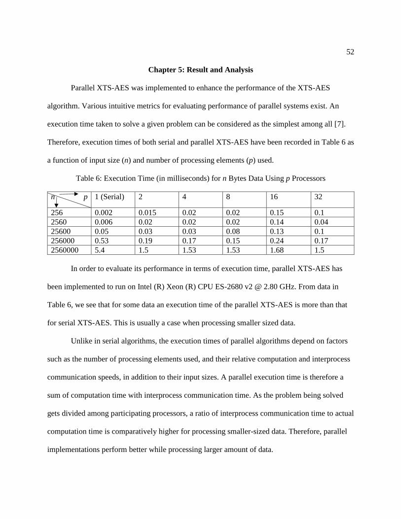
Therefore, execution times of both serial and parallel XTS-AES have been recorded in Table 6 as
a function of input size (n) and number of processing elements (p) used.
Table 6: Execution Time (in milliseconds) for n Bytes Data Using p Processors
n p 1 (Serial) 2 4 8 16 32
256 0.002 0.015 0.02 0.02 0.15 0.1
2560 0.006 0.02 0.02 0.02 0.14 0.04
25600 0.05 0.03 0.03 0.08 0.13 0.1
256000 0.53 0.19 0.17 0.15 0.24 0.17
2560000 5.4 1.5 1.53 1.53 1.68 1.5
In order to evaluate its performance in terms of execution time, parallel XTS-AES has
been implemented to run on Intel (R) Xeon (R) CPU ES-2680 v2 @ 2.80 GHz. From data in
Table 6, we see that for some data an execution time of the parallel XTS-AES is more than that
for serial XTS-AES. This is usually a case when processing smaller sized data.
Unlike in serial algorithms, the execution times of parallel algorithms depend on factors
such as the number of processing elements used, and their relative computation and interprocess
communication speeds, in addition to their input sizes. A parallel execution time is therefore a
sum of computation time with interprocess communication time. As the problem being solved
gets divided among participating processors, a ratio of interprocess communication time to actual
computation time is comparatively higher for processing smaller-sized data. Therefore, parallel
implementations perform better while processing larger amount of data.

53
As a parallel algorithm cannot be evaluated in isolation from an underlying parallel
architecture without some loss in accuracy, some other intuitive metrics, such as speedup, have
also been calculated to see how faster XTS_AES_ Encrypt.c run compared to
XTS_AES_Serial.c.
Table 7: Speedup of XTS-AES Algorithm for n Bytes Data Using p Processors
n p 2 4 8 16 32
256 0.13 0.1 0.1 0.01 0.02
2560 0.3 0.3 0.3 0.04 0.15
25600 2 2 0.6 0.6 0.6
256000 2.8 3.1 3.5 2.2 3.1
2560000 3.6 3.5 3.5 3.2 3.6
Speedup is defined as a ratio of time taken to solve a problem using a single processing
unit to time required to solve the same problem on a parallel computer with p identical
processing units. Basically, speedup is used to capture a relative benefit of solving a problem in
parallel. From the data in Table 7, the average speedup of implemented parallel XTS-AES was
calculated to be 1.6. Theoretically, speedup can never exceed the number of processing elements,
p. In practice, a speedup greater than p might be sometimes observed when work performed by a
serial algorithm is greater than its parallel formulation, or due to hardware features that put the
serial implementation at a disadvantage. This phenomenon, termed super linear speedup, been
observed in this project couple of times.
Efficiency is another metric that is used to measure performance of a parallel program. It
is a measure of a fraction of time for which a processing element is usefully employed and is
calculated as a ratio of speedup to the number of parallel processing elements used. For
XTS_AES_ Encrypt.c, we found it to be 37%. In the case of an ideal parallel system with p

54
processing elements, a speedup of p can be observed. When speedup is equal to p, the efficiency
is equal to one. However, the inability of parallel processing elements to devote 100% of their
time to computation prevents it from being 100% efficient.
In addition to speedup and efficiency, correctness of this program has been verified by
decrypting the output ciphertexts. A parallel XTS_AES_Decrypt.c (in Appendix B) has been
implemented similarly in C using MPI for decryption. Upon decrypting, output plaintexts were
found to be identical with input plaintexts in input.txt file.
The ability of a parallel program to utilize increasing processing resources effectively is
called its scalability. It is an important property of any parallel algorithm. It indicates the
capability of a program to increase speedup in proportion to the number of processing elements.
As performance and correctness of the program are much more difficult to establish based on
programs written and tested for smaller problems on fewer processing elements, efficiency has
been evaluated under two scenarios:
1. First, for a given problem size, the number of processing elements has been increased.
In this case, the efficiency of the parallel program went down as shown in Figure 13.
This is a common characteristic of all parallel programs.

55
Figure 13: Variation of Efficiency as the Number of Processing Elements is
Increased for 256000-byte Data
2. Then, the problem size has been increased, keeping the number of processing elements
constant. In this case, efficiency increases with an increase in the problem size, as
shown in Figure 14.
Figure 14: Variation of Efficiency as the Problem Size is Increased for Four Processing Elements
0
0.2
0.4
0.6
0.8
1
1.2
1.4
1.6
1.8
2
0 5 10 15 20 25 30 35
Effi
cien
cy
Number of Processors (p)
0
0.1
0.2
0.3
0.4
0.5
0.6
0.7
0.8
0.9
1
-500000 0 500000 1000000 1500000 2000000 2500000 3000000
Effi
cien
cy
Data Size (Bytes)

56
For algorithms exhibiting such characteristics, efficiency could be made more consistent
by increasing both the problem size and the number of processing elements simultaneously.
Table 8: Efficiency as a Function of n Bytes Input Data on p Processing Elements
n p 2 4 8 16 32
256 0.1 0.1 0.025 0.0125 0.001
2560 0.15 0.1 0.04 0.03 0.005
25600 1 0.5 0.1 0.03 0.02
256000 1.4 0.8 0.4 0.1 0.1
2560000 1.8 0.9 0.4 0.2 0.1
In Table 8, the efficiency of encrypting 256-byte data using two processors is 0.1. If the
number of processors is increased to 4, and the problem size is increased to 2560-byte, the
efficiency remains 0.1. Increasing p to 8 and n to 25600 results in the same efficiency. Thus, this
parallel XTS-AES system can be termed a scalable parallel system since its efficiency remains
0.1 with an increasing number of processing elements, provided that the problem size is also
increased.
57
Chapter 6: Conclusion
Currently, data encryption is gaining popularity within organizations. Increasing trends in
disk encryption show that focus has extended from encrypting data-in-motion to data-at-rest. As
a result, using more computing units to process larger amounts of data not only increases the rate
of data processing but also makes the process comparatively more efficient. XTS is an important
mode of AES operation as it provides the flexibility of encrypting data independently. This
feature of XTS supports encryption of stored data in parallel.
The message passing model is one of the oldest parallel programming models used
widely to write programs that run on parallel computers. MPI, a message passing library
interface is a de facto standard for creating portable message-passing parallel programs that can
execute across distributed computing nodes. Currently, such programs also run on hybrid
systems that contain multi-core CPUs on a single node or connected via a network.
The main objective of this project has been to implement XTS-AES algorithm in parallel.
It was preceded by parallel XTS-AES algorithm design. A methodological approach of parallel
XTS-AES design has been presented in this paper which provides the theory on how the
encryption is carried out by multiple processors. For our implementation, MPI was used to pass
messages among processors and to synchronize their actions. Also, the performance of the
parallel XTS-AES algorithm was analyzed against its serial implementation. Our results from
our analyses show that the implemented parallel XTS-AES algorithm correctly performed
encryption with speedup equal to 1.6 and with 37% efficiency. Further, we showed that the
parallel XTS-AES algorithm is scalable, as the efficiency remained constant (e.g., 10%) when
the number of processing elements and data size both were increased at a constant rate.

58
Therefore, this implementation can be used to efficiently and reliably encrypt larger amounts of
data by using more processors.

59
References
[1] “Consumer Notice–Cybersecurity Incident & Important Consumer Information | Equifax,”
n.d., https://www.equifaxsecurity2017.com/consumer-notice/#notice.
[2] A. Andriotis, M. Rapoport, and R. McMillan, “‘We’ve been breached’: Inside the Equifax
hack” [Editorial], The Wall Street Journal, September 18, 2017, https://www.wsj.com/
articles/weve-been-breached-inside-the-equifax-hack-1505693318.
[3] “2017 Poor Internal Security Practices Take a Toll” (Rep.),” Gemalto, n.d., http://
breachlevelindex.com/assets/Breach-Level-Index-Report-H1-2017-Gemalto.pdf.
[4] W. Stallings, Cryptography and Network Security Principles and Practice. Boston:
Pearson, 2017.
[5] B. Barney, “Introduction to Parallel Computing: Part 1,” January 29, 2009, http://www.
ddj.com/go-parallel/article/showArticle.jhtml?articleID=212903586.
[6] J. Ortega, H. Trefftz, and C. Trefftz, “Parallelizing AES on multicores and GPUs
[Scholarly project],” in Parallelizing AES on Multicores and GPUs, August 8, 2011,
http://ieeexplore.ieee.org/abstract/document/5978576/authors.
[7] “Fifty Years of Microprocessor Technology Advancements: 1965 to 2015,” Itanium
Solutions Alliance, n.d.
[8] M. J. Flynn, “Very high-speed computing systems,” December 1966, http://ieeexplore.
ieee.org/document/1447203/authors.
[9] I. Foster, I. (1995). Designing and Building Parallel Programs: Concepts and Tools for
Parallel Software Engineering. Reading, MA: Addison-Wesley, 1995, http://www.
mcs.anl.gov/~itf/dbpp/.
[10] A. Grama, A. Gupta, G. Karypis, and V. Kumar, Introduction to Parallel Computing,
Second Edition. Addison-Wesley, 2003.
[11] “MPI: A Message-Passing Interface Standard Version 3.1,” June 4, 2015.
[12] B. Barney, n.d., https://computing.llnl.gov/tutorials/mpi/.
[13] M. Alomari and K. Samsudin, “A Parallel XTS Encryption Mode of Operation”
[Scholarly project], April 5, 2010, http://ieeexplore.ieee.org/document/5443177/.
60
[14] Information Technology Laboratory (National Institute of Standards and Technology).
“Announcing the Advanced Encryption Standard (AES),” Gaithersburg, MD: Computer
Security Division, Information Technology Laboratory, National Institute of Standards
and Technology, 2001.
[15] D. Kinghorn, “5 Ways of Parallel Programming,” May 12, 2015, https://www.
pugetsystems.com/labs/hpc/5-Ways-of-Parallel-Programming-652/.
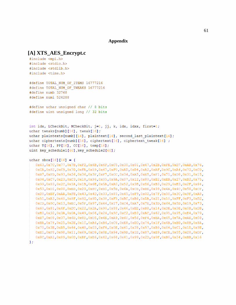
61
Appendix
[A] XTS_AES_Encrypt.c
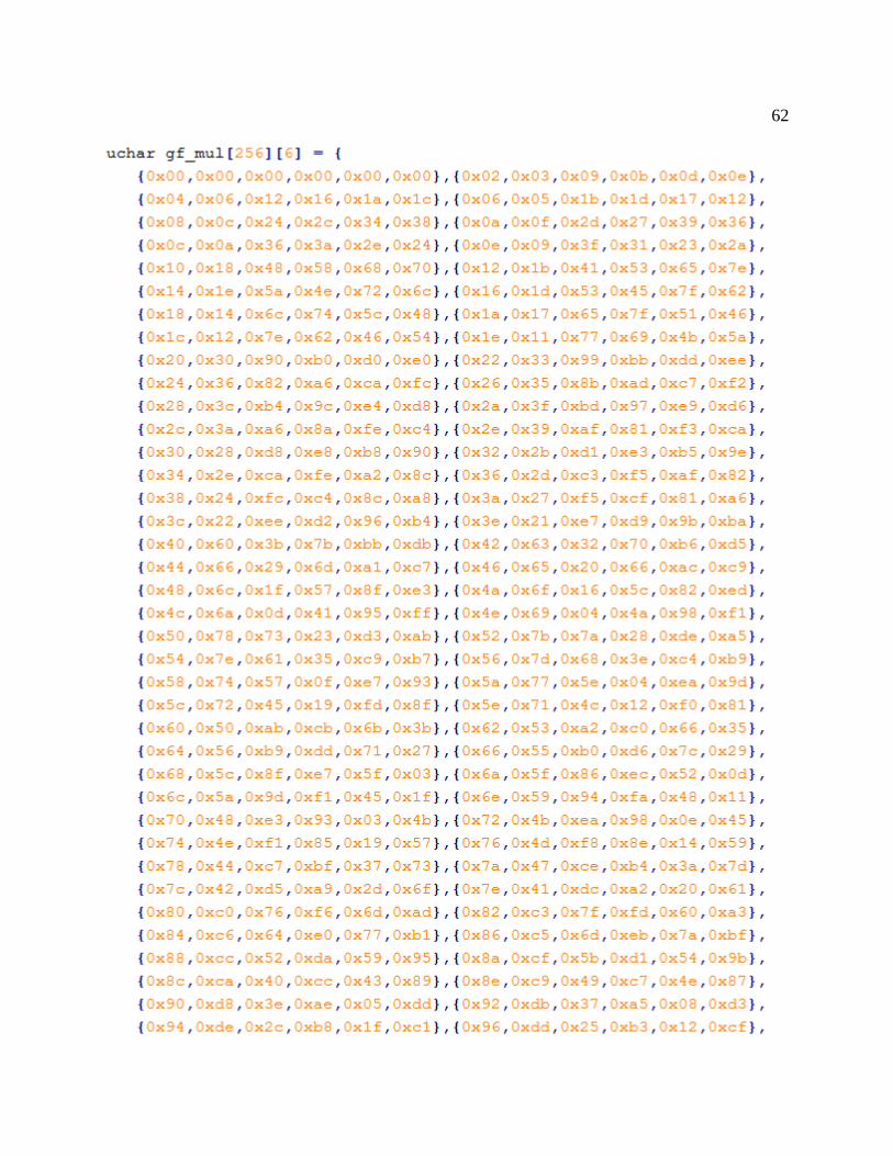
62
63

64

65

66

67

68
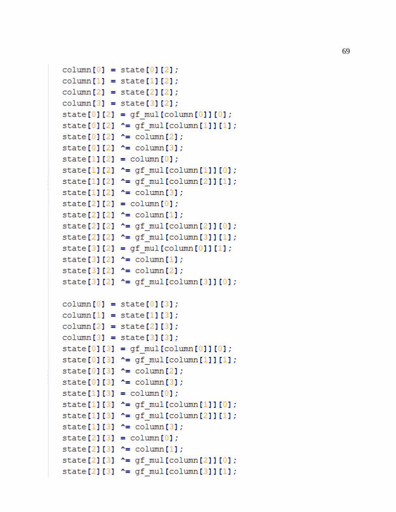
69

70
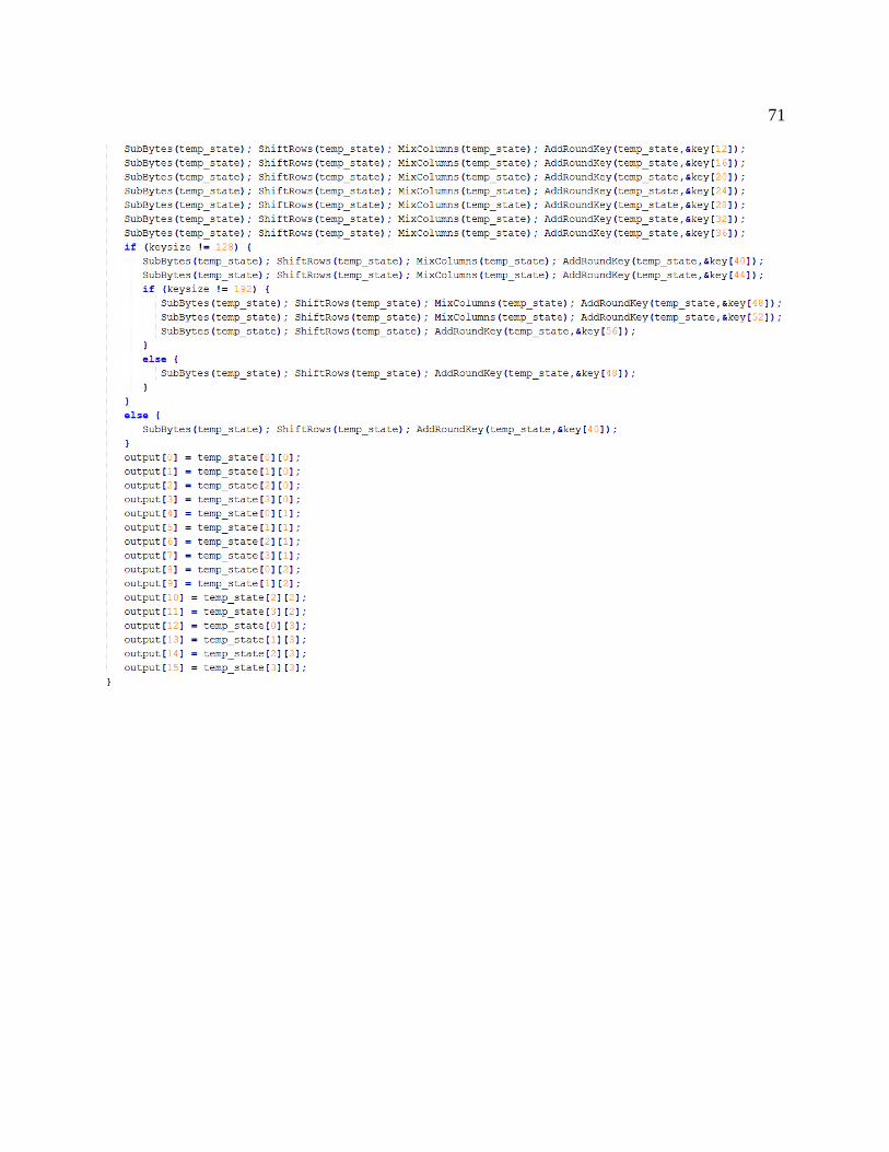
71

72
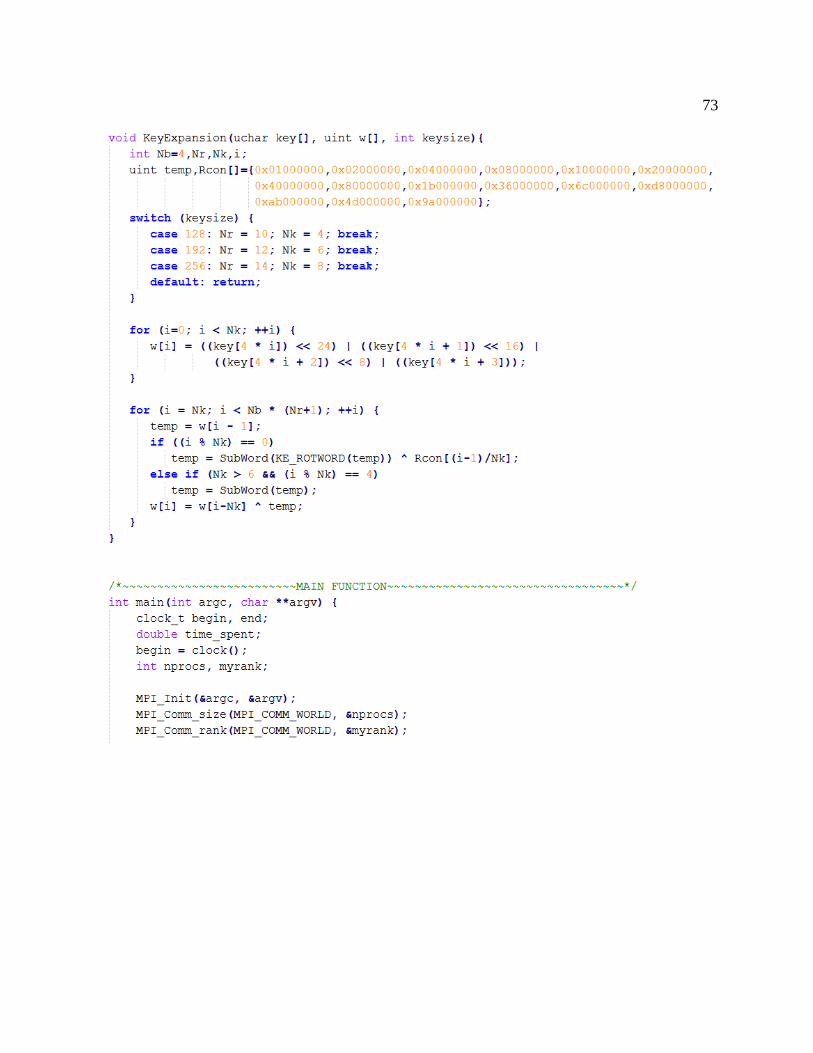
73
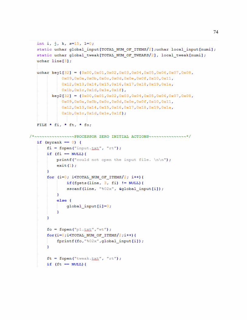
74
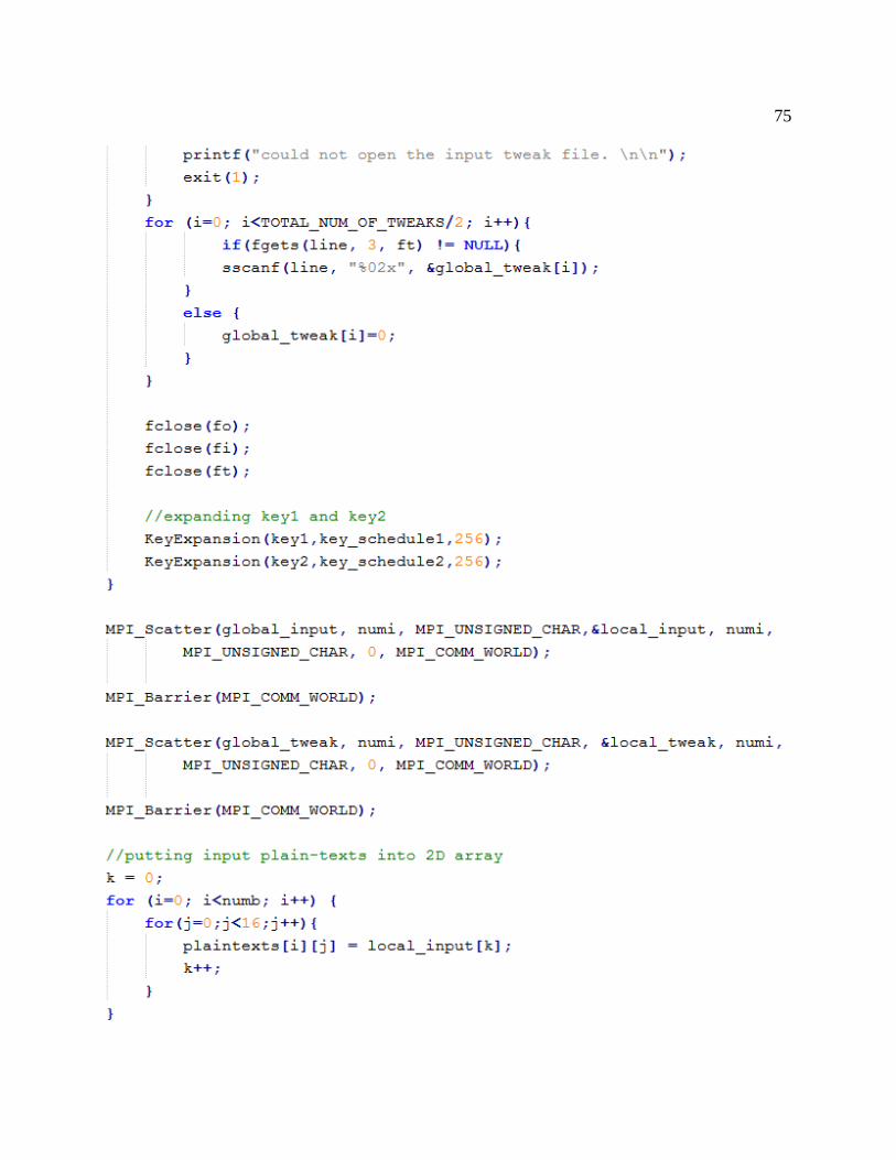
75

76
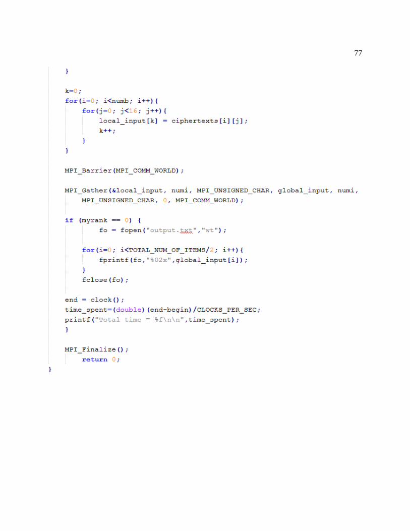
77
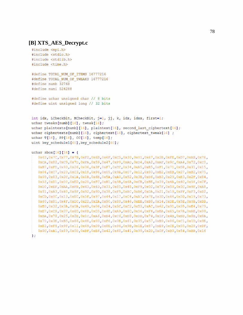
78
[B] XTS_AES_Decrypt.c
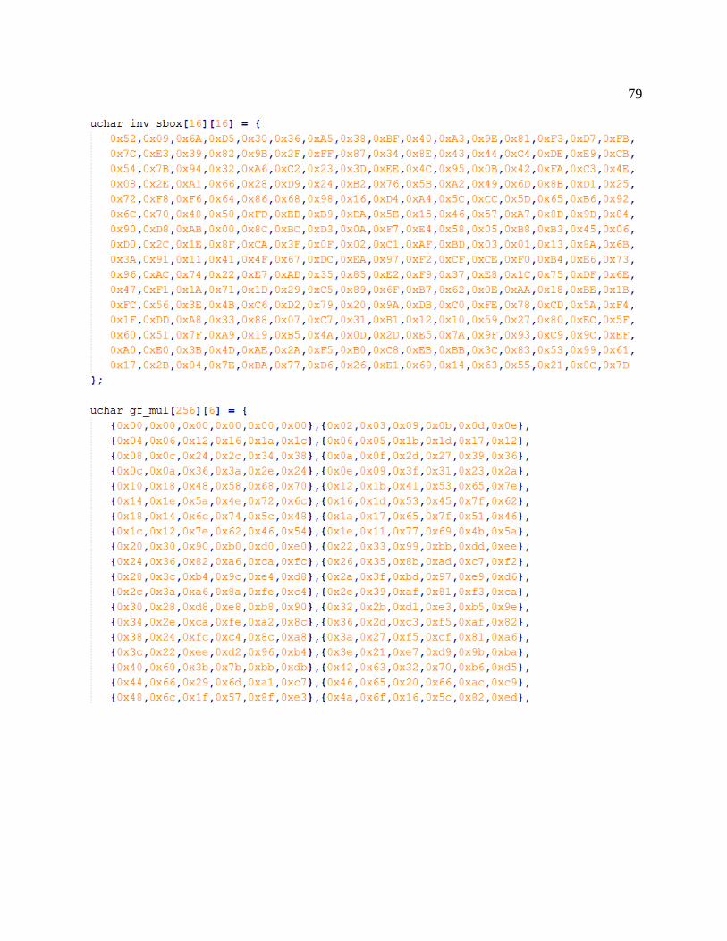
79

80

81
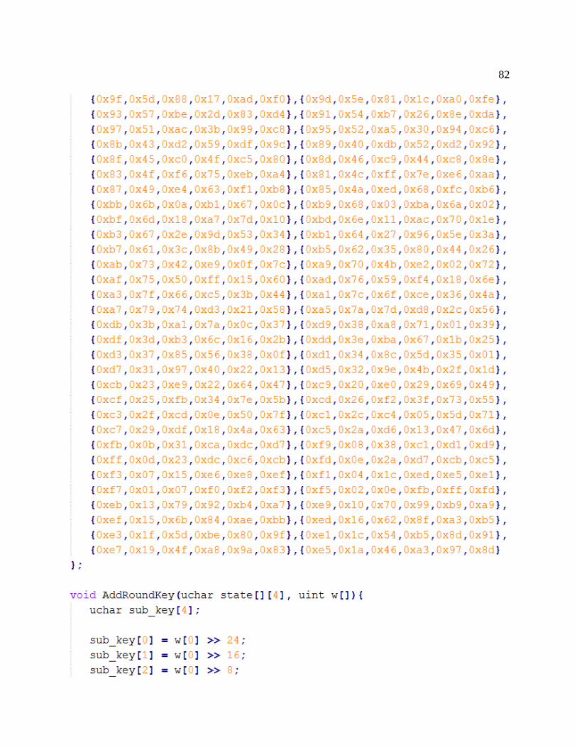
82
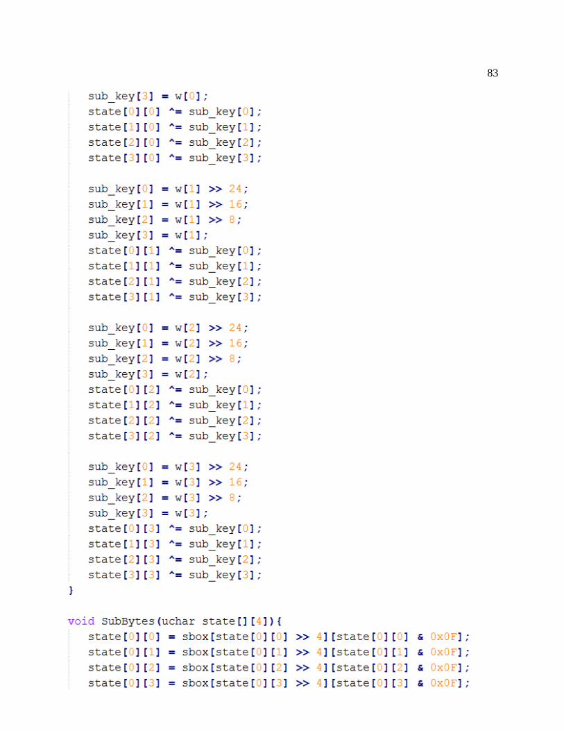
83

84

85

86
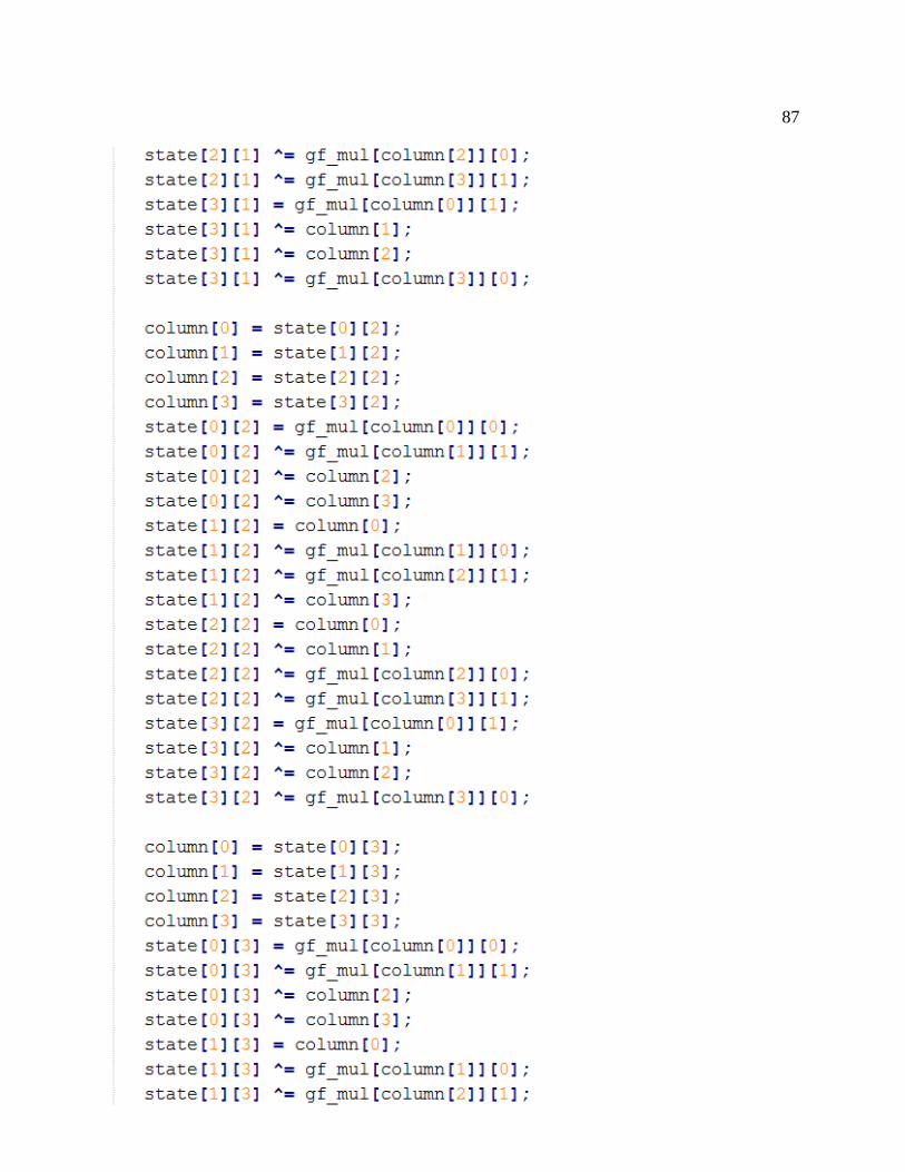
87
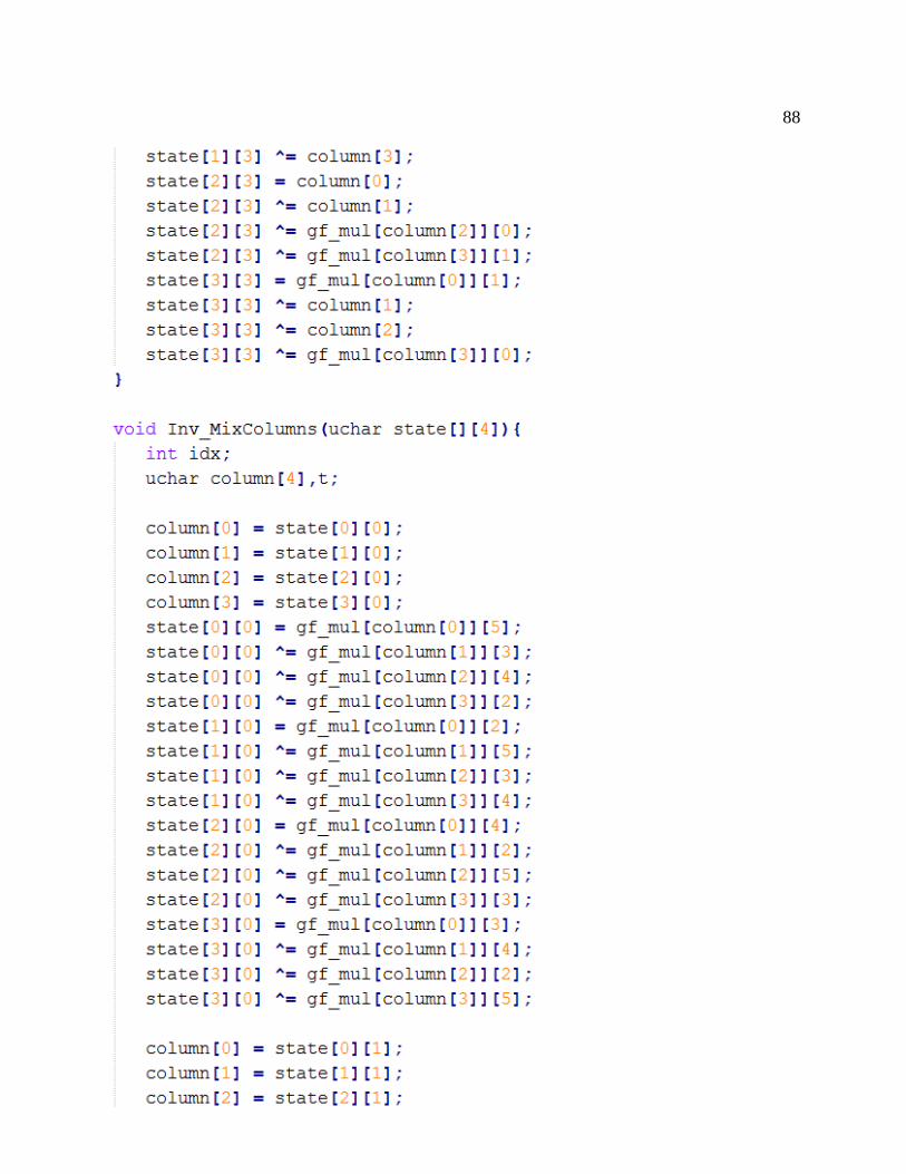
88

89

90
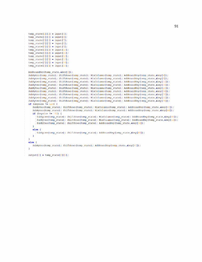
91
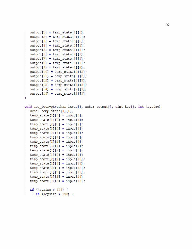
92
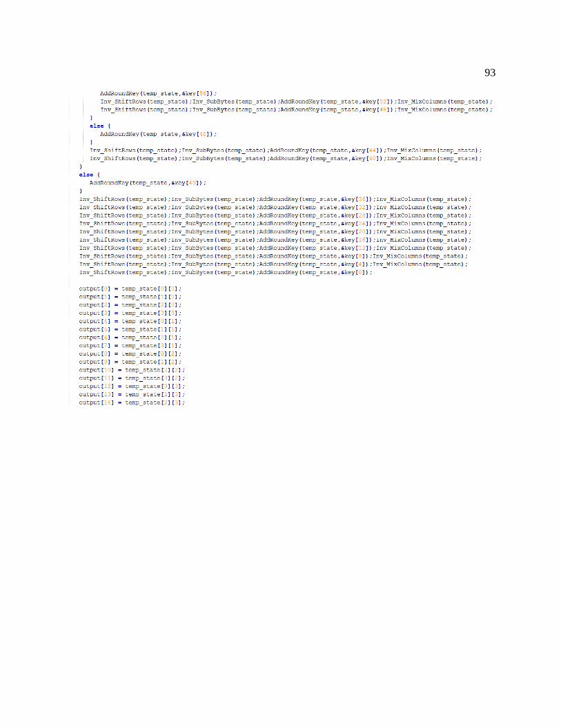
93

94

95
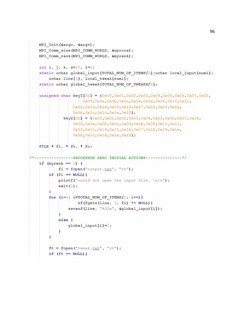
96
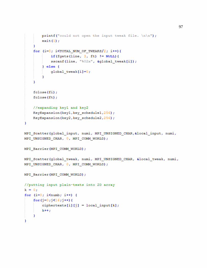
97

98

99
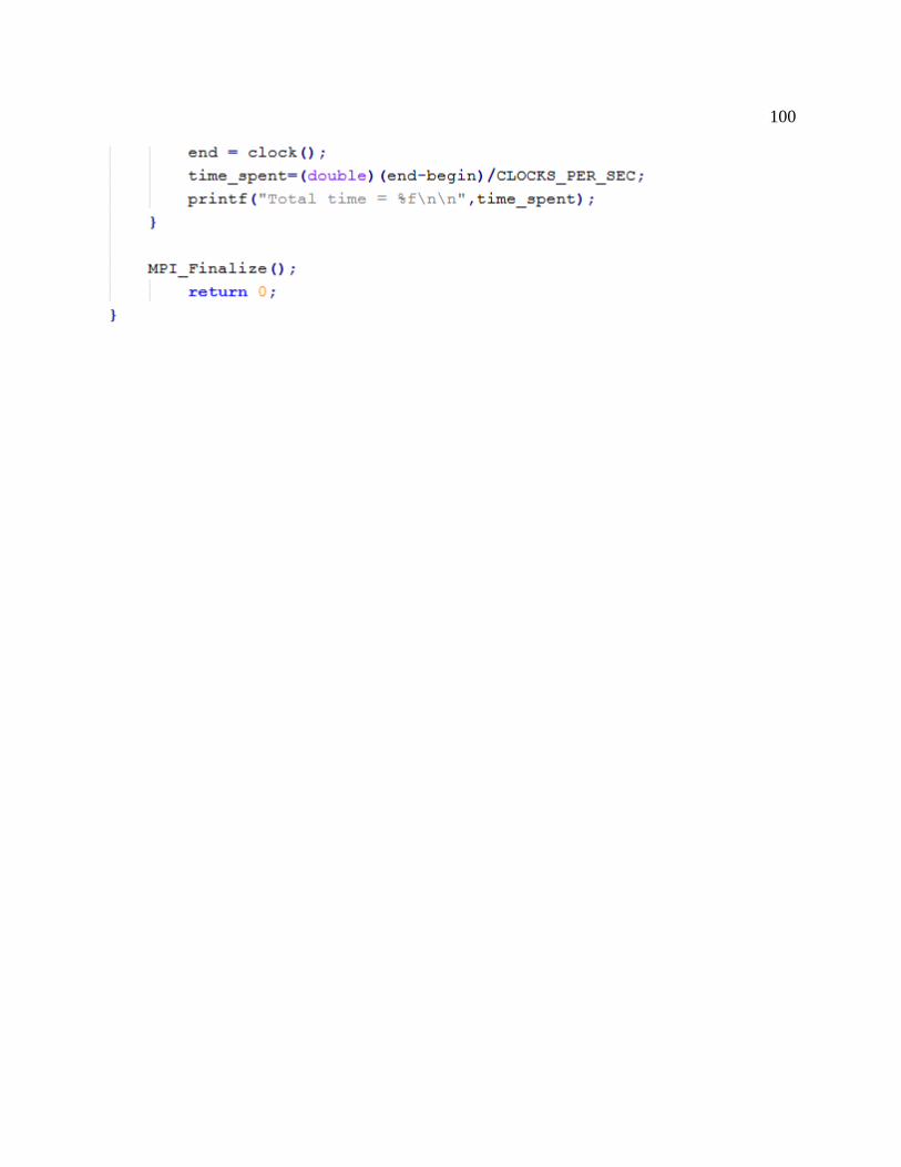
100

101
[C] XTS_AES_Serial.c

102

103
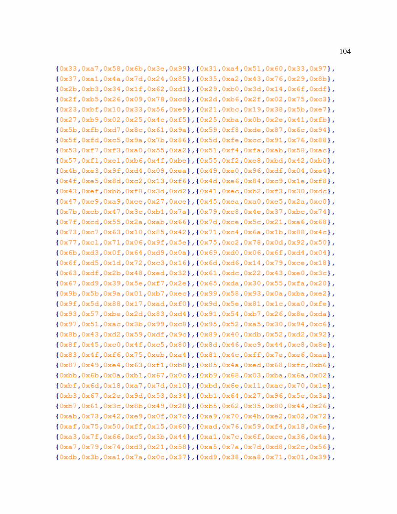
104

105

106
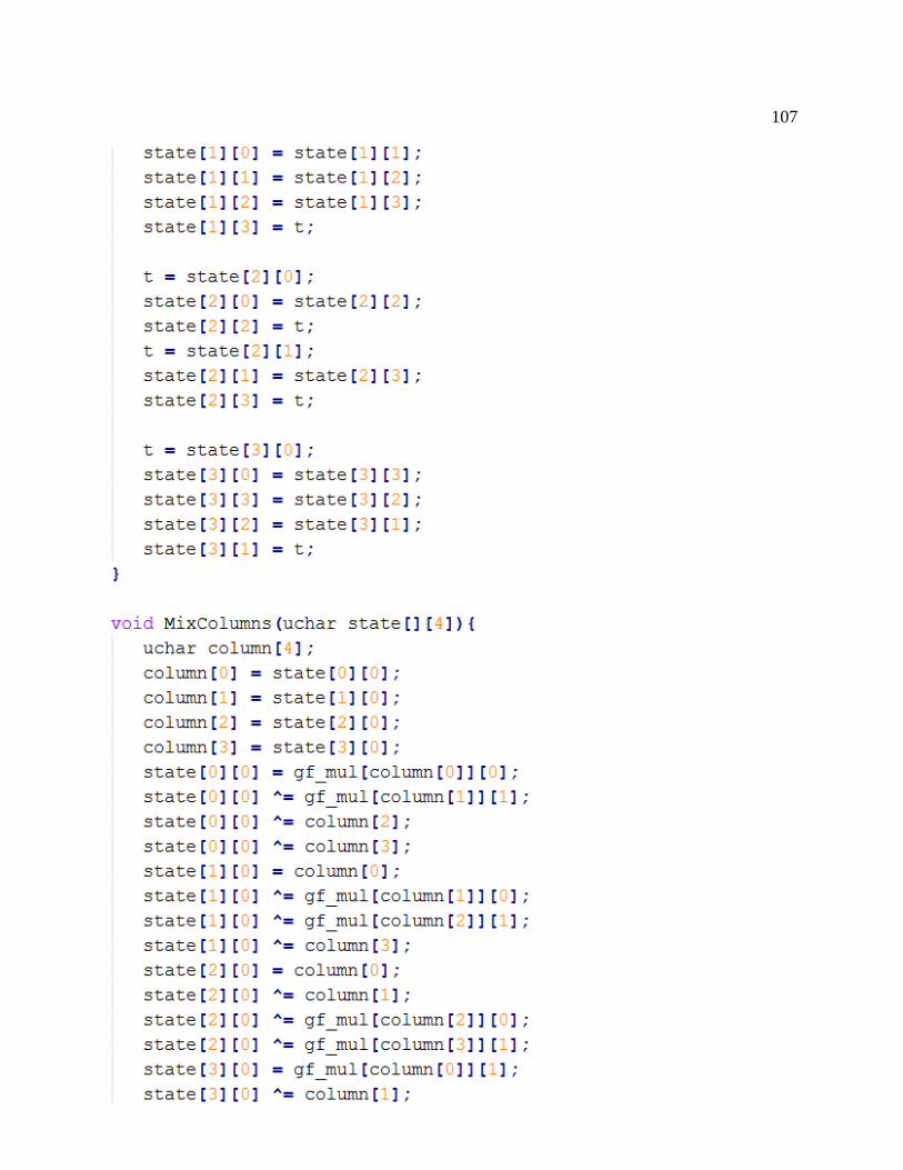
107
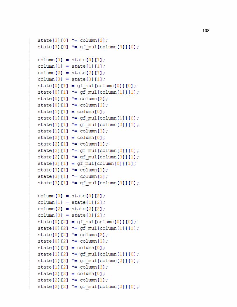
108

109

110

111

112
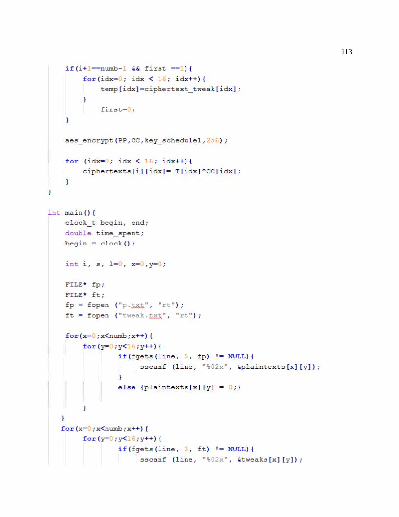
113
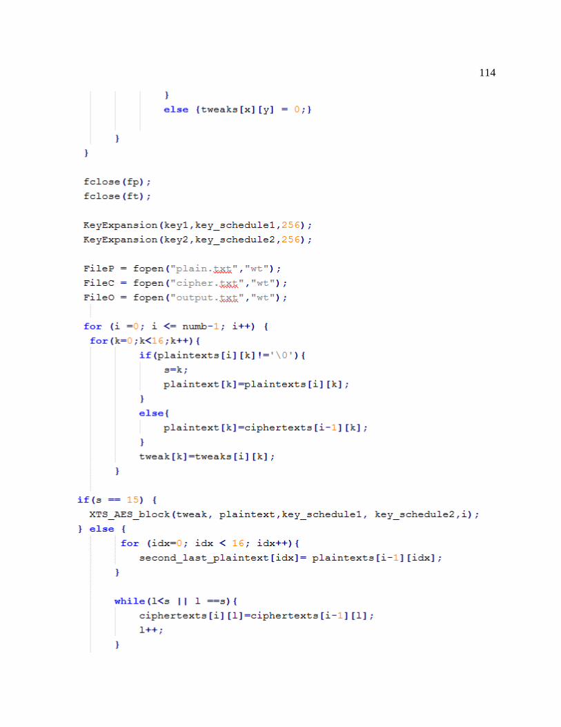
114
115