Original instructions
Electric trucks
RX60-35/600RX60-40RX60-40/600RX60-45RX60-45/600RX60-50RX60-50/600
6327 6328 6329 6330 63676368 6369
171533 EN - 02/2019 - 19


Prefaceg
Address of manufacturer andcontact detailsSTILL GmbHBerzeliusstraße 1022113 Hamburg, GermanyTel. +49 (0) 40 7339-0Fax: +49 (0) 40 7339-1622Email: [email protected]: http://www.still.de
Rules for the operatingcompany of industrial trucksIn addition to these operating instructions,a code of practice containing additionalinformation for the operating companies ofindustrial trucks is also available.
This guide provides information for handlingindustrial trucks:• Information on how to select suitableindustrial trucks for a particular area ofapplication
• Prerequisites for the safe operation ofindustrial trucks
• Information on the use of industrial trucks• Information on transport, initial commis-sioning and storage of industrial trucks
Internet address and QR codeThe information can be accessed at any timeby pasting the address https://m.still.de/vdmain a web browser or by scanning the QR code.
171533 EN - 02/2019 - 19 I

Table of contentsg
1 ForewordYour truck . . . . . . . . . . . . . . . . . . . . . . . . . . . . . . . . . . . . . . . . . . . . . . . . . . . . . . . . . . 2Description of the truck . . . . . . . . . . . . . . . . . . . . . . . . . . . . . . . . . . . . . . . . . . . . . . . . . 2General . . . . . . . . . . . . . . . . . . . . . . . . . . . . . . . . . . . . . . . . . . . . . . . . . . . . . . . . . . . . 4CE labelling . . . . . . . . . . . . . . . . . . . . . . . . . . . . . . . . . . . . . . . . . . . . . . . . . . . . . . . . . 5EC declaration of conformity in accordance with Machinery Directive . . . . . . . . . . . . . . . 6Accessories . . . . . . . . . . . . . . . . . . . . . . . . . . . . . . . . . . . . . . . . . . . . . . . . . . . . . . . . . 7Labelling points . . . . . . . . . . . . . . . . . . . . . . . . . . . . . . . . . . . . . . . . . . . . . . . . . . . . . . 8Nameplate . . . . . . . . . . . . . . . . . . . . . . . . . . . . . . . . . . . . . . . . . . . . . . . . . . . . . . . . . 10Production number . . . . . . . . . . . . . . . . . . . . . . . . . . . . . . . . . . . . . . . . . . . . . . . . . . 10StVZO (Road Traffic Licensing Regulations) information . . . . . . . . . . . . . . . . . . . . . . . 11Nameplate of a lithium-ion battery . . . . . . . . . . . . . . . . . . . . . . . . . . . . . . . . . . . . . . . . 11
Using the truck . . . . . . . . . . . . . . . . . . . . . . . . . . . . . . . . . . . . . . . . . . . . . . . . . . . . . . 11Commissioning . . . . . . . . . . . . . . . . . . . . . . . . . . . . . . . . . . . . . . . . . . . . . . . . . . . . . 11Proper usage . . . . . . . . . . . . . . . . . . . . . . . . . . . . . . . . . . . . . . . . . . . . . . . . . . . . . . . 12Proper use during towing . . . . . . . . . . . . . . . . . . . . . . . . . . . . . . . . . . . . . . . . . . . . . . 12Impermissible use . . . . . . . . . . . . . . . . . . . . . . . . . . . . . . . . . . . . . . . . . . . . . . . . . . . 13Place of use . . . . . . . . . . . . . . . . . . . . . . . . . . . . . . . . . . . . . . . . . . . . . . . . . . . . . . . . 13Parking in temperatures below -10°C . . . . . . . . . . . . . . . . . . . . . . . . . . . . . . . . . . . . . 14Using working platforms . . . . . . . . . . . . . . . . . . . . . . . . . . . . . . . . . . . . . . . . . . . . . . . 15
Information about the documentation . . . . . . . . . . . . . . . . . . . . . . . . . . . . . . . . . . . . . 16Documentation scope . . . . . . . . . . . . . . . . . . . . . . . . . . . . . . . . . . . . . . . . . . . . . . . . 16Supplementary documentation . . . . . . . . . . . . . . . . . . . . . . . . . . . . . . . . . . . . . . . . . . 17Issue date and topicality of the operating instructions . . . . . . . . . . . . . . . . . . . . . . . . . . 18Copyright and trademark rights . . . . . . . . . . . . . . . . . . . . . . . . . . . . . . . . . . . . . . . . . . 18Explanation of information symbols used . . . . . . . . . . . . . . . . . . . . . . . . . . . . . . . . . . 18List of abbreviations . . . . . . . . . . . . . . . . . . . . . . . . . . . . . . . . . . . . . . . . . . . . . . . . . . 19Definition of directions . . . . . . . . . . . . . . . . . . . . . . . . . . . . . . . . . . . . . . . . . . . . . . . . 21Schematic views . . . . . . . . . . . . . . . . . . . . . . . . . . . . . . . . . . . . . . . . . . . . . . . . . . . . 21
Environmental considerations . . . . . . . . . . . . . . . . . . . . . . . . . . . . . . . . . . . . . . . . . . 23Packaging . . . . . . . . . . . . . . . . . . . . . . . . . . . . . . . . . . . . . . . . . . . . . . . . . . . . . . . . . 23Disposal of components and batteries . . . . . . . . . . . . . . . . . . . . . . . . . . . . . . . . . . . . . 23
2 SafetyDefinition of responsible persons . . . . . . . . . . . . . . . . . . . . . . . . . . . . . . . . . . . . . . . . 26Operating company . . . . . . . . . . . . . . . . . . . . . . . . . . . . . . . . . . . . . . . . . . . . . . . . . . 26Specialist . . . . . . . . . . . . . . . . . . . . . . . . . . . . . . . . . . . . . . . . . . . . . . . . . . . . . . . . . . 26Drivers . . . . . . . . . . . . . . . . . . . . . . . . . . . . . . . . . . . . . . . . . . . . . . . . . . . . . . . . . . . 27
Basic principles for safe operation . . . . . . . . . . . . . . . . . . . . . . . . . . . . . . . . . . . . . . . 29Insurance cover on company premises . . . . . . . . . . . . . . . . . . . . . . . . . . . . . . . . . . . . 29
171533 EN - 02/2019 - 19 III
Table of contentsg
Special features when using lithium-ion batteries (variant) . . . . . . . . . . . . . . . . . . . . . . 30Changes and retrofitting . . . . . . . . . . . . . . . . . . . . . . . . . . . . . . . . . . . . . . . . . . . . . . . 33Changes to the overhead guard and roof loads . . . . . . . . . . . . . . . . . . . . . . . . . . . . . . 36Warning regarding non-original parts . . . . . . . . . . . . . . . . . . . . . . . . . . . . . . . . . . . . . 36Damage, defects andmisuse of safety systems . . . . . . . . . . . . . . . . . . . . . . . . . . . . . . 37Tyres . . . . . . . . . . . . . . . . . . . . . . . . . . . . . . . . . . . . . . . . . . . . . . . . . . . . . . . . . . . . . 37Medical equipment . . . . . . . . . . . . . . . . . . . . . . . . . . . . . . . . . . . . . . . . . . . . . . . . . . . 38Exercise caution when handling gas springs and accumulators . . . . . . . . . . . . . . . . . . 39Length of the fork arms . . . . . . . . . . . . . . . . . . . . . . . . . . . . . . . . . . . . . . . . . . . . . . . . 39
Residual risk . . . . . . . . . . . . . . . . . . . . . . . . . . . . . . . . . . . . . . . . . . . . . . . . . . . . . . . 41Residual dangers, residual risks . . . . . . . . . . . . . . . . . . . . . . . . . . . . . . . . . . . . . . . . . 41Special risks associated with using the truck and attachments . . . . . . . . . . . . . . . . . . . 42Overview of hazards and countermeasures . . . . . . . . . . . . . . . . . . . . . . . . . . . . . . . . . 44Danger to employees . . . . . . . . . . . . . . . . . . . . . . . . . . . . . . . . . . . . . . . . . . . . . . . . . 47
Safety tests . . . . . . . . . . . . . . . . . . . . . . . . . . . . . . . . . . . . . . . . . . . . . . . . . . . . . . . . 48Regular safety inspection of the truck . . . . . . . . . . . . . . . . . . . . . . . . . . . . . . . . . . . . . 48Insulation testing . . . . . . . . . . . . . . . . . . . . . . . . . . . . . . . . . . . . . . . . . . . . . . . . . . . . 48
Safety regulations for handling consumables . . . . . . . . . . . . . . . . . . . . . . . . . . . . . . . 50Permissible consumables . . . . . . . . . . . . . . . . . . . . . . . . . . . . . . . . . . . . . . . . . . . . . 50Oils . . . . . . . . . . . . . . . . . . . . . . . . . . . . . . . . . . . . . . . . . . . . . . . . . . . . . . . . . . . . . . 50Hydraulic fluid . . . . . . . . . . . . . . . . . . . . . . . . . . . . . . . . . . . . . . . . . . . . . . . . . . . . . . 51Battery acid . . . . . . . . . . . . . . . . . . . . . . . . . . . . . . . . . . . . . . . . . . . . . . . . . . . . . . . . 52Disposal of consumables . . . . . . . . . . . . . . . . . . . . . . . . . . . . . . . . . . . . . . . . . . . . . . 53
Emissions . . . . . . . . . . . . . . . . . . . . . . . . . . . . . . . . . . . . . . . . . . . . . . . . . . . . . . . . . 54
3 OverviewsGeneral view . . . . . . . . . . . . . . . . . . . . . . . . . . . . . . . . . . . . . . . . . . . . . . . . . . . . . . . 58
General view of driver's compartment . . . . . . . . . . . . . . . . . . . . . . . . . . . . . . . . . . . . . 60
Shelves and cup holders . . . . . . . . . . . . . . . . . . . . . . . . . . . . . . . . . . . . . . . . . . . . . . 61
Operating devices and display elements . . . . . . . . . . . . . . . . . . . . . . . . . . . . . . . . . . . 62Display operating unit . . . . . . . . . . . . . . . . . . . . . . . . . . . . . . . . . . . . . . . . . . . . . . . . . 62Lithium-ion battery display . . . . . . . . . . . . . . . . . . . . . . . . . . . . . . . . . . . . . . . . . . . . . 63Operating devices for hydraulic and traction functions . . . . . . . . . . . . . . . . . . . . . . . . . 64Multi-lever . . . . . . . . . . . . . . . . . . . . . . . . . . . . . . . . . . . . . . . . . . . . . . . . . . . . . . . . . 65Double mini-lever . . . . . . . . . . . . . . . . . . . . . . . . . . . . . . . . . . . . . . . . . . . . . . . . . . . . 66Three-way mini-lever . . . . . . . . . . . . . . . . . . . . . . . . . . . . . . . . . . . . . . . . . . . . . . . . . 67Four-way mini-lever . . . . . . . . . . . . . . . . . . . . . . . . . . . . . . . . . . . . . . . . . . . . . . . . . . 68Joystick 4Plus . . . . . . . . . . . . . . . . . . . . . . . . . . . . . . . . . . . . . . . . . . . . . . . . . . . . . . 69Fingertip . . . . . . . . . . . . . . . . . . . . . . . . . . . . . . . . . . . . . . . . . . . . . . . . . . . . . . . . . . 70
IV 171533 EN - 02/2019 - 19

Table of contentsg
Mini console . . . . . . . . . . . . . . . . . . . . . . . . . . . . . . . . . . . . . . . . . . . . . . . . . . . . . . . 71
4 OperationChecks and tasks before daily use . . . . . . . . . . . . . . . . . . . . . . . . . . . . . . . . . . . . . . . 74Visual inspections and function checking . . . . . . . . . . . . . . . . . . . . . . . . . . . . . . . . . . 74Climbing into and out of the truck . . . . . . . . . . . . . . . . . . . . . . . . . . . . . . . . . . . . . . . . 77Adjusting the MSG 65/MSG 75 driver's seat . . . . . . . . . . . . . . . . . . . . . . . . . . . . . . . . 78Seat belt . . . . . . . . . . . . . . . . . . . . . . . . . . . . . . . . . . . . . . . . . . . . . . . . . . . . . . . . . . 82Adjusting the armrest . . . . . . . . . . . . . . . . . . . . . . . . . . . . . . . . . . . . . . . . . . . . . . . . . 85Adjusting the steering column . . . . . . . . . . . . . . . . . . . . . . . . . . . . . . . . . . . . . . . . . . . 86Unlocking the emergency off switch . . . . . . . . . . . . . . . . . . . . . . . . . . . . . . . . . . . . . . 87Operating the signal horn . . . . . . . . . . . . . . . . . . . . . . . . . . . . . . . . . . . . . . . . . . . . . . 88Driver's cab . . . . . . . . . . . . . . . . . . . . . . . . . . . . . . . . . . . . . . . . . . . . . . . . . . . . . . . . 89Checking the brake system for correct function . . . . . . . . . . . . . . . . . . . . . . . . . . . . . . 90Checking the steering system for correct function . . . . . . . . . . . . . . . . . . . . . . . . . . . . 93Checking the emergency off function . . . . . . . . . . . . . . . . . . . . . . . . . . . . . . . . . . . . . 94Checking the vertical lift mast position (variant) for correct function . . . . . . . . . . . . . . . . 95Zero adjustment of the load measurement (variant) . . . . . . . . . . . . . . . . . . . . . . . . . . . 95
Switching on . . . . . . . . . . . . . . . . . . . . . . . . . . . . . . . . . . . . . . . . . . . . . . . . . . . . . . . 97Switching on the key switch . . . . . . . . . . . . . . . . . . . . . . . . . . . . . . . . . . . . . . . . . . . . 97Access authorisation with PIN code (variant) . . . . . . . . . . . . . . . . . . . . . . . . . . . . . . . . 99
Display-operating unit . . . . . . . . . . . . . . . . . . . . . . . . . . . . . . . . . . . . . . . . . . . . . . . . 109Indicators . . . . . . . . . . . . . . . . . . . . . . . . . . . . . . . . . . . . . . . . . . . . . . . . . . . . . . . . . 109Adjusting the displays . . . . . . . . . . . . . . . . . . . . . . . . . . . . . . . . . . . . . . . . . . . . . . . . 111Symbols in the display . . . . . . . . . . . . . . . . . . . . . . . . . . . . . . . . . . . . . . . . . . . . . . . . 113Setting the date or time . . . . . . . . . . . . . . . . . . . . . . . . . . . . . . . . . . . . . . . . . . . . . . . . 118Resetting the daily kilometres and daily operating hours . . . . . . . . . . . . . . . . . . . . . . . 118Setting the language . . . . . . . . . . . . . . . . . . . . . . . . . . . . . . . . . . . . . . . . . . . . . . . . . 119Softkeys for operating various equipment variants . . . . . . . . . . . . . . . . . . . . . . . . . . . . 119
Blue-Q efficiency mode . . . . . . . . . . . . . . . . . . . . . . . . . . . . . . . . . . . . . . . . . . . . . . . 121Functional description . . . . . . . . . . . . . . . . . . . . . . . . . . . . . . . . . . . . . . . . . . . . . . . . 121Switching off additional consumers . . . . . . . . . . . . . . . . . . . . . . . . . . . . . . . . . . . . . . . 122Switching efficiency mode Blue-Q on and off . . . . . . . . . . . . . . . . . . . . . . . . . . . . . . . . 122Configuring Blue-Q efficiency mode . . . . . . . . . . . . . . . . . . . . . . . . . . . . . . . . . . . . . . 123
Driving . . . . . . . . . . . . . . . . . . . . . . . . . . . . . . . . . . . . . . . . . . . . . . . . . . . . . . . . . . . . 125Safety regulations when driving . . . . . . . . . . . . . . . . . . . . . . . . . . . . . . . . . . . . . . . . . 125Driveways . . . . . . . . . . . . . . . . . . . . . . . . . . . . . . . . . . . . . . . . . . . . . . . . . . . . . . . . . 127Setting the drive programs . . . . . . . . . . . . . . . . . . . . . . . . . . . . . . . . . . . . . . . . . . . . . 130Sprint mode (variant) . . . . . . . . . . . . . . . . . . . . . . . . . . . . . . . . . . . . . . . . . . . . . . . . . 132Selecting the drive direction . . . . . . . . . . . . . . . . . . . . . . . . . . . . . . . . . . . . . . . . . . . . 133
171533 EN - 02/2019 - 19 V
Table of contentsg
Actuating the drive direction switch, multiple-lever version . . . . . . . . . . . . . . . . . . . . . . 134Actuating the drive direction switch, mini-lever version . . . . . . . . . . . . . . . . . . . . . . . . . 134Actuating the vertical rocker switch for the "drive direction", joystick 4Plus version . . . . 135Actuate the drive direction switch, fingertip version . . . . . . . . . . . . . . . . . . . . . . . . . . . 135Actuating the drive direction switch, mini-console version . . . . . . . . . . . . . . . . . . . . . . 136Starting drive mode . . . . . . . . . . . . . . . . . . . . . . . . . . . . . . . . . . . . . . . . . . . . . . . . . . 136Starting drive mode, dual-pedal version (variant) . . . . . . . . . . . . . . . . . . . . . . . . . . . . . 138Operating the service brake . . . . . . . . . . . . . . . . . . . . . . . . . . . . . . . . . . . . . . . . . . . . 141Parking brake . . . . . . . . . . . . . . . . . . . . . . . . . . . . . . . . . . . . . . . . . . . . . . . . . . . . . . 142Actuating the mechanical parking brake . . . . . . . . . . . . . . . . . . . . . . . . . . . . . . . . . . . 142Actuate the electric parking brake . . . . . . . . . . . . . . . . . . . . . . . . . . . . . . . . . . . . . . . . 144Malfunctions in the electric parking brake . . . . . . . . . . . . . . . . . . . . . . . . . . . . . . . . . . 150Steering . . . . . . . . . . . . . . . . . . . . . . . . . . . . . . . . . . . . . . . . . . . . . . . . . . . . . . . . . . . 157Reducing speed when turning (Curve Speed Control) . . . . . . . . . . . . . . . . . . . . . . . . . 158Reducing speed with a raised load (variant) . . . . . . . . . . . . . . . . . . . . . . . . . . . . . . . . 159
Parking . . . . . . . . . . . . . . . . . . . . . . . . . . . . . . . . . . . . . . . . . . . . . . . . . . . . . . . . . . . 160Parking the truck securely and switching it off . . . . . . . . . . . . . . . . . . . . . . . . . . . . . . . 160Wheel chock (variant) . . . . . . . . . . . . . . . . . . . . . . . . . . . . . . . . . . . . . . . . . . . . . . . . 161
Lifting . . . . . . . . . . . . . . . . . . . . . . . . . . . . . . . . . . . . . . . . . . . . . . . . . . . . . . . . . . . . 162Lifting system variants . . . . . . . . . . . . . . . . . . . . . . . . . . . . . . . . . . . . . . . . . . . . . . . . 162Types of lift mast . . . . . . . . . . . . . . . . . . . . . . . . . . . . . . . . . . . . . . . . . . . . . . . . . . . . 162Lifting system operating devices . . . . . . . . . . . . . . . . . . . . . . . . . . . . . . . . . . . . . . . . . 163Multi-lever lifting system . . . . . . . . . . . . . . . . . . . . . . . . . . . . . . . . . . . . . . . . . . . . . . . 164Controlling the lifting system using a double mini-lever . . . . . . . . . . . . . . . . . . . . . . . . . 165Controlling the lifting system using a triple mini-lever . . . . . . . . . . . . . . . . . . . . . . . . . . 166Controlling the lifting system using a quadruple mini-lever . . . . . . . . . . . . . . . . . . . . . . 167Controlling the lifting system using the joystick 4Plus . . . . . . . . . . . . . . . . . . . . . . . . . . 168Controlling the lifting system with the fingertip console . . . . . . . . . . . . . . . . . . . . . . . . . 170Changing the fork arms . . . . . . . . . . . . . . . . . . . . . . . . . . . . . . . . . . . . . . . . . . . . . . . 171Fork extension (variant) . . . . . . . . . . . . . . . . . . . . . . . . . . . . . . . . . . . . . . . . . . . . . . . 173Operation with reversible fork arms (variant) . . . . . . . . . . . . . . . . . . . . . . . . . . . . . . . . 175Malfunctions during lifting mode . . . . . . . . . . . . . . . . . . . . . . . . . . . . . . . . . . . . . . . . . 176Hydraulic blocking function . . . . . . . . . . . . . . . . . . . . . . . . . . . . . . . . . . . . . . . . . . . . . 177Automatic lift cut out (variant) . . . . . . . . . . . . . . . . . . . . . . . . . . . . . . . . . . . . . . . . . . . 178Lift mast vertical position (variant) . . . . . . . . . . . . . . . . . . . . . . . . . . . . . . . . . . . . . . . . 179
Handling loads . . . . . . . . . . . . . . . . . . . . . . . . . . . . . . . . . . . . . . . . . . . . . . . . . . . . . . 184Safety regulations when handing loads . . . . . . . . . . . . . . . . . . . . . . . . . . . . . . . . . . . . 184Before taking up load . . . . . . . . . . . . . . . . . . . . . . . . . . . . . . . . . . . . . . . . . . . . . . . . . 185Loadmeasurement (variant) . . . . . . . . . . . . . . . . . . . . . . . . . . . . . . . . . . . . . . . . . . . 186Picking up loads . . . . . . . . . . . . . . . . . . . . . . . . . . . . . . . . . . . . . . . . . . . . . . . . . . . . . 189Danger area . . . . . . . . . . . . . . . . . . . . . . . . . . . . . . . . . . . . . . . . . . . . . . . . . . . . . . . 190
VI 171533 EN - 02/2019 - 19
Table of contentsg
Transporting pallets . . . . . . . . . . . . . . . . . . . . . . . . . . . . . . . . . . . . . . . . . . . . . . . . . . 191Transporting suspended loads . . . . . . . . . . . . . . . . . . . . . . . . . . . . . . . . . . . . . . . . . . 191Load pick up . . . . . . . . . . . . . . . . . . . . . . . . . . . . . . . . . . . . . . . . . . . . . . . . . . . . . . . 192Transporting loads . . . . . . . . . . . . . . . . . . . . . . . . . . . . . . . . . . . . . . . . . . . . . . . . . . . 196Setting down loads . . . . . . . . . . . . . . . . . . . . . . . . . . . . . . . . . . . . . . . . . . . . . . . . . . . 197Driving on ascending and descending gradients . . . . . . . . . . . . . . . . . . . . . . . . . . . . . 199Driving on lifts . . . . . . . . . . . . . . . . . . . . . . . . . . . . . . . . . . . . . . . . . . . . . . . . . . . . . . 200Driving on loading bridges . . . . . . . . . . . . . . . . . . . . . . . . . . . . . . . . . . . . . . . . . . . . . 201
Attachments . . . . . . . . . . . . . . . . . . . . . . . . . . . . . . . . . . . . . . . . . . . . . . . . . . . . . . . 202Fitting attachments . . . . . . . . . . . . . . . . . . . . . . . . . . . . . . . . . . . . . . . . . . . . . . . . . . 202Releasing the pressure from the hydraulic system . . . . . . . . . . . . . . . . . . . . . . . . . . . . 204General instructions for controlling attachments . . . . . . . . . . . . . . . . . . . . . . . . . . . . . 208Controlling attachments using multi-lever operation . . . . . . . . . . . . . . . . . . . . . . . . . . . 210Operating attachments using multi-lever controls and the 5th function . . . . . . . . . . . . . 211Controlling attachments using a double mini-lever . . . . . . . . . . . . . . . . . . . . . . . . . . . . 213Controlling attachments using the double mini-lever and the 5th function . . . . . . . . . . . 215Controlling attachments using a triple mini-lever . . . . . . . . . . . . . . . . . . . . . . . . . . . . . 217Controlling attachments using the triple mini-lever and the 5th function . . . . . . . . . . . . . 219Controlling attachments using a quadruple mini-lever . . . . . . . . . . . . . . . . . . . . . . . . . 221Controlling attachments using the quadruple mini-lever and the 5th function . . . . . . . . . 223Controlling attachments using the Joystick 4Plus . . . . . . . . . . . . . . . . . . . . . . . . . . . . . 225Controlling attachments with Joystick 4Plus and the 5th function . . . . . . . . . . . . . . . . . 227Controlling the attachments with fingertip . . . . . . . . . . . . . . . . . . . . . . . . . . . . . . . . . . 229Controlling attachments with fingertip and the 5th function . . . . . . . . . . . . . . . . . . . . . . 230Clamp locking mechanism (variant) . . . . . . . . . . . . . . . . . . . . . . . . . . . . . . . . . . . . . . 232Taking up a load using attachments . . . . . . . . . . . . . . . . . . . . . . . . . . . . . . . . . . . . . . 236
Auxiliary equipment . . . . . . . . . . . . . . . . . . . . . . . . . . . . . . . . . . . . . . . . . . . . . . . . . . 237Switching the lighting on and off . . . . . . . . . . . . . . . . . . . . . . . . . . . . . . . . . . . . . . . . . 237Switching the working spotlight for reverse travel on and off . . . . . . . . . . . . . . . . . . . . . 238Switching the rotating beacon on and off . . . . . . . . . . . . . . . . . . . . . . . . . . . . . . . . . . . 238Switching the hazard warning system on and off . . . . . . . . . . . . . . . . . . . . . . . . . . . . . 239Switching the turn indicators on and off . . . . . . . . . . . . . . . . . . . . . . . . . . . . . . . . . . . . 239Switching the double working spotlights on and off. . . . . . . . . . . . . . . . . . . . . . . . . . . . 242STILL SafetyLight (variant) . . . . . . . . . . . . . . . . . . . . . . . . . . . . . . . . . . . . . . . . . . . . . 244Operating the windscreen wiper/washer . . . . . . . . . . . . . . . . . . . . . . . . . . . . . . . . . . . 245Filling the washer system . . . . . . . . . . . . . . . . . . . . . . . . . . . . . . . . . . . . . . . . . . . . . . 245FleetManager (variant) . . . . . . . . . . . . . . . . . . . . . . . . . . . . . . . . . . . . . . . . . . . . . . . . 246Shock recognition (variant) . . . . . . . . . . . . . . . . . . . . . . . . . . . . . . . . . . . . . . . . . . . . . 246Driver restraint systems (variants) . . . . . . . . . . . . . . . . . . . . . . . . . . . . . . . . . . . . . . . 246Ceiling sensor (variant) . . . . . . . . . . . . . . . . . . . . . . . . . . . . . . . . . . . . . . . . . . . . . . . 247
171533 EN - 02/2019 - 19 VII

Table of contentsg
Cab . . . . . . . . . . . . . . . . . . . . . . . . . . . . . . . . . . . . . . . . . . . . . . . . . . . . . . . . . . . . . . 253Opening the cab door . . . . . . . . . . . . . . . . . . . . . . . . . . . . . . . . . . . . . . . . . . . . . . . . . 253Closing the cab door . . . . . . . . . . . . . . . . . . . . . . . . . . . . . . . . . . . . . . . . . . . . . . . . . 254Opening the side windows . . . . . . . . . . . . . . . . . . . . . . . . . . . . . . . . . . . . . . . . . . . . . 254Closing the side windows . . . . . . . . . . . . . . . . . . . . . . . . . . . . . . . . . . . . . . . . . . . . . . 254Operating the interior lighting . . . . . . . . . . . . . . . . . . . . . . . . . . . . . . . . . . . . . . . . . . . 255Operating the rear window heating . . . . . . . . . . . . . . . . . . . . . . . . . . . . . . . . . . . . . . . 256Radio (variant) . . . . . . . . . . . . . . . . . . . . . . . . . . . . . . . . . . . . . . . . . . . . . . . . . . . . . . 256Heating system (variant) . . . . . . . . . . . . . . . . . . . . . . . . . . . . . . . . . . . . . . . . . . . . . . 257Push-up roof window (variant) . . . . . . . . . . . . . . . . . . . . . . . . . . . . . . . . . . . . . . . . . . 259Clipboard (variant) . . . . . . . . . . . . . . . . . . . . . . . . . . . . . . . . . . . . . . . . . . . . . . . . . . . 260
Trailer operation . . . . . . . . . . . . . . . . . . . . . . . . . . . . . . . . . . . . . . . . . . . . . . . . . . . . 261Towed load . . . . . . . . . . . . . . . . . . . . . . . . . . . . . . . . . . . . . . . . . . . . . . . . . . . . . . . . 261Coupling pin in the counterweight . . . . . . . . . . . . . . . . . . . . . . . . . . . . . . . . . . . . . . . . 262Automatic tow coupling . . . . . . . . . . . . . . . . . . . . . . . . . . . . . . . . . . . . . . . . . . . . . . . 264Towing trailers . . . . . . . . . . . . . . . . . . . . . . . . . . . . . . . . . . . . . . . . . . . . . . . . . . . . . . 272
Cold store application . . . . . . . . . . . . . . . . . . . . . . . . . . . . . . . . . . . . . . . . . . . . . . . . . 274
Display messages . . . . . . . . . . . . . . . . . . . . . . . . . . . . . . . . . . . . . . . . . . . . . . . . . . . 277Display content . . . . . . . . . . . . . . . . . . . . . . . . . . . . . . . . . . . . . . . . . . . . . . . . . . . . . 277Error code table . . . . . . . . . . . . . . . . . . . . . . . . . . . . . . . . . . . . . . . . . . . . . . . . . . . . . 277General messages . . . . . . . . . . . . . . . . . . . . . . . . . . . . . . . . . . . . . . . . . . . . . . . . . . . 282Drive-specific messages . . . . . . . . . . . . . . . . . . . . . . . . . . . . . . . . . . . . . . . . . . . . . . 291
Procedure in emergencies . . . . . . . . . . . . . . . . . . . . . . . . . . . . . . . . . . . . . . . . . . . . . 295Emergency shutdown . . . . . . . . . . . . . . . . . . . . . . . . . . . . . . . . . . . . . . . . . . . . . . . . 295Procedure if truck tips over . . . . . . . . . . . . . . . . . . . . . . . . . . . . . . . . . . . . . . . . . . . . . 296Emergency hammer . . . . . . . . . . . . . . . . . . . . . . . . . . . . . . . . . . . . . . . . . . . . . . . . . . 297Emergency lowering . . . . . . . . . . . . . . . . . . . . . . . . . . . . . . . . . . . . . . . . . . . . . . . . . 297Emergency operation of the electric parking brake . . . . . . . . . . . . . . . . . . . . . . . . . . . . 299Towing . . . . . . . . . . . . . . . . . . . . . . . . . . . . . . . . . . . . . . . . . . . . . . . . . . . . . . . . . . . 300
Connecting and disconnecting the battery male connector . . . . . . . . . . . . . . . . . . . . . . 303Connecting the battery male connector . . . . . . . . . . . . . . . . . . . . . . . . . . . . . . . . . . . . 303Disconnecting the battery male connector . . . . . . . . . . . . . . . . . . . . . . . . . . . . . . . . . . 304
Handling the lead-acid battery . . . . . . . . . . . . . . . . . . . . . . . . . . . . . . . . . . . . . . . . . . 305Safety regulations for handling the battery . . . . . . . . . . . . . . . . . . . . . . . . . . . . . . . . . . 305Maintaining the battery . . . . . . . . . . . . . . . . . . . . . . . . . . . . . . . . . . . . . . . . . . . . . . . . 308Checking the battery condition, acid level and acid density . . . . . . . . . . . . . . . . . . . . . . 310Checking the battery charge status . . . . . . . . . . . . . . . . . . . . . . . . . . . . . . . . . . . . . . . 311Charging the battery . . . . . . . . . . . . . . . . . . . . . . . . . . . . . . . . . . . . . . . . . . . . . . . . . . 311Charging the battery with the battery charging flap . . . . . . . . . . . . . . . . . . . . . . . . . . . . 314Equalising charging to preserve the battery capacity . . . . . . . . . . . . . . . . . . . . . . . . . . 318
VIII 171533 EN - 02/2019 - 19
Table of contentsg
Handling the lithium-ion battery . . . . . . . . . . . . . . . . . . . . . . . . . . . . . . . . . . . . . . . . . 321Safety regulations for handling the lithium-ion battery . . . . . . . . . . . . . . . . . . . . . . . . . 321Lithium-ion batteries "GGS Li-Ion 80 V BG 7"36.2 kWh and 118.4 kWh . . . . . . . . . . . . . 324Display messages on the display-operating unit . . . . . . . . . . . . . . . . . . . . . . . . . . . . . 325Regulations for storing lithium-ion batteries . . . . . . . . . . . . . . . . . . . . . . . . . . . . . . . . . 325Checking the battery charge state . . . . . . . . . . . . . . . . . . . . . . . . . . . . . . . . . . . . . . . . 328Charging the battery . . . . . . . . . . . . . . . . . . . . . . . . . . . . . . . . . . . . . . . . . . . . . . . . . . 331
Replacing and transporting the battery . . . . . . . . . . . . . . . . . . . . . . . . . . . . . . . . . . . . 333General information on replacing the battery . . . . . . . . . . . . . . . . . . . . . . . . . . . . . . . . 333Changing to a different battery type . . . . . . . . . . . . . . . . . . . . . . . . . . . . . . . . . . . . . . . 334Opening/closing the battery cover . . . . . . . . . . . . . . . . . . . . . . . . . . . . . . . . . . . . . . . . 334Special notes for installing the lithium-ion battery . . . . . . . . . . . . . . . . . . . . . . . . . . . . . 337Replacing the battery using forklift truck or pallet truck . . . . . . . . . . . . . . . . . . . . . . . . . 338Replacing the battery using a change frame (variant) . . . . . . . . . . . . . . . . . . . . . . . . . . 341Replacing the battery with the hydraulic battery carrier . . . . . . . . . . . . . . . . . . . . . . . . . 345Transporting the lead-acid battery by crane . . . . . . . . . . . . . . . . . . . . . . . . . . . . . . . . . 353Transporting the lithium-ion battery by crane . . . . . . . . . . . . . . . . . . . . . . . . . . . . . . . . 354
Cleaning the truck . . . . . . . . . . . . . . . . . . . . . . . . . . . . . . . . . . . . . . . . . . . . . . . . . . . 355Cleaning the truck . . . . . . . . . . . . . . . . . . . . . . . . . . . . . . . . . . . . . . . . . . . . . . . . . . . 355Cleaning the electrical system . . . . . . . . . . . . . . . . . . . . . . . . . . . . . . . . . . . . . . . . . . 357Clean load chains . . . . . . . . . . . . . . . . . . . . . . . . . . . . . . . . . . . . . . . . . . . . . . . . . . . 357Cleaning the windows . . . . . . . . . . . . . . . . . . . . . . . . . . . . . . . . . . . . . . . . . . . . . . . . 358After cleaning . . . . . . . . . . . . . . . . . . . . . . . . . . . . . . . . . . . . . . . . . . . . . . . . . . . . . . . 358
Transporting the truck . . . . . . . . . . . . . . . . . . . . . . . . . . . . . . . . . . . . . . . . . . . . . . . . 360Transport . . . . . . . . . . . . . . . . . . . . . . . . . . . . . . . . . . . . . . . . . . . . . . . . . . . . . . . . . . 360Crane loading . . . . . . . . . . . . . . . . . . . . . . . . . . . . . . . . . . . . . . . . . . . . . . . . . . . . . . 362
Decommissioning . . . . . . . . . . . . . . . . . . . . . . . . . . . . . . . . . . . . . . . . . . . . . . . . . . . 366Decommissioning and storing the truck . . . . . . . . . . . . . . . . . . . . . . . . . . . . . . . . . . . . 366Returning to service after decommissioning . . . . . . . . . . . . . . . . . . . . . . . . . . . . . . . . 368
5 MaintenanceSafety regulations for maintenance . . . . . . . . . . . . . . . . . . . . . . . . . . . . . . . . . . . . . . . 372General information . . . . . . . . . . . . . . . . . . . . . . . . . . . . . . . . . . . . . . . . . . . . . . . . . . 372Working on the hydraulic equipment . . . . . . . . . . . . . . . . . . . . . . . . . . . . . . . . . . . . . . 372Working on the electrical equipment . . . . . . . . . . . . . . . . . . . . . . . . . . . . . . . . . . . . . . 372Safety devices . . . . . . . . . . . . . . . . . . . . . . . . . . . . . . . . . . . . . . . . . . . . . . . . . . . . . . 373Set values . . . . . . . . . . . . . . . . . . . . . . . . . . . . . . . . . . . . . . . . . . . . . . . . . . . . . . . . . 373Lifting and jacking up . . . . . . . . . . . . . . . . . . . . . . . . . . . . . . . . . . . . . . . . . . . . . . . . . 373Working at the front of the truck . . . . . . . . . . . . . . . . . . . . . . . . . . . . . . . . . . . . . . . . . . 374
171533 EN - 02/2019 - 19 IX
Table of contentsg
General maintenance information . . . . . . . . . . . . . . . . . . . . . . . . . . . . . . . . . . . . . . . . 376Personnel qualifications . . . . . . . . . . . . . . . . . . . . . . . . . . . . . . . . . . . . . . . . . . . . . . . 376Information for carrying out maintenance . . . . . . . . . . . . . . . . . . . . . . . . . . . . . . . . . . 376Maintenance— 1000 hours/annually . . . . . . . . . . . . . . . . . . . . . . . . . . . . . . . . . . . . . 379Maintenance - 3000 hours/every two years . . . . . . . . . . . . . . . . . . . . . . . . . . . . . . . . . 383Ordering spare parts and wearing parts . . . . . . . . . . . . . . . . . . . . . . . . . . . . . . . . . . . . 383Quality and quantity of the required operating materials . . . . . . . . . . . . . . . . . . . . . . . . 383Lubrication plan . . . . . . . . . . . . . . . . . . . . . . . . . . . . . . . . . . . . . . . . . . . . . . . . . . . . . 385Maintenance data table . . . . . . . . . . . . . . . . . . . . . . . . . . . . . . . . . . . . . . . . . . . . . . . 387
Providing access to maintenance points . . . . . . . . . . . . . . . . . . . . . . . . . . . . . . . . . . . 390Removing and installing the valve cover . . . . . . . . . . . . . . . . . . . . . . . . . . . . . . . . . . . 390Opening the fuse box . . . . . . . . . . . . . . . . . . . . . . . . . . . . . . . . . . . . . . . . . . . . . . . . . 390
Preserving operational readiness . . . . . . . . . . . . . . . . . . . . . . . . . . . . . . . . . . . . . . . . 392Lubricating the joints and controls . . . . . . . . . . . . . . . . . . . . . . . . . . . . . . . . . . . . . . . . 392Checking the battery interlock and battery cover . . . . . . . . . . . . . . . . . . . . . . . . . . . . . 392Maintaining the seat belt . . . . . . . . . . . . . . . . . . . . . . . . . . . . . . . . . . . . . . . . . . . . . . . 394Checking the driver's seat . . . . . . . . . . . . . . . . . . . . . . . . . . . . . . . . . . . . . . . . . . . . . 395Maintaining wheels and tyres . . . . . . . . . . . . . . . . . . . . . . . . . . . . . . . . . . . . . . . . . . . 396Servicing the steering axle . . . . . . . . . . . . . . . . . . . . . . . . . . . . . . . . . . . . . . . . . . . . . 398Checking the battery . . . . . . . . . . . . . . . . . . . . . . . . . . . . . . . . . . . . . . . . . . . . . . . . . 400Checking the fuses . . . . . . . . . . . . . . . . . . . . . . . . . . . . . . . . . . . . . . . . . . . . . . . . . . . 400Replacing fuses . . . . . . . . . . . . . . . . . . . . . . . . . . . . . . . . . . . . . . . . . . . . . . . . . . . . . 402Checking the hydraulic oil level . . . . . . . . . . . . . . . . . . . . . . . . . . . . . . . . . . . . . . . . . . 404Checking the hydraulic system for leak tightness . . . . . . . . . . . . . . . . . . . . . . . . . . . . . 405Lubricating the lift mast and roller track . . . . . . . . . . . . . . . . . . . . . . . . . . . . . . . . . . . . 406Greasing the automatic tow coupling . . . . . . . . . . . . . . . . . . . . . . . . . . . . . . . . . . . . . . 406Preserving operational readiness for cold store application . . . . . . . . . . . . . . . . . . . . . 409Maintaining the heater . . . . . . . . . . . . . . . . . . . . . . . . . . . . . . . . . . . . . . . . . . . . . . . . 409
1000-hour maintenance/yearly maintenance . . . . . . . . . . . . . . . . . . . . . . . . . . . . . . . 411Other tasks . . . . . . . . . . . . . . . . . . . . . . . . . . . . . . . . . . . . . . . . . . . . . . . . . . . . . . . . 411Checking the cable connections . . . . . . . . . . . . . . . . . . . . . . . . . . . . . . . . . . . . . . . . . 411Checking the hydraulic oil level of the hydraulic battery carrier . . . . . . . . . . . . . . . . . . . 411Lubricating the slide elements . . . . . . . . . . . . . . . . . . . . . . . . . . . . . . . . . . . . . . . . . . 413Oiling the catch rails . . . . . . . . . . . . . . . . . . . . . . . . . . . . . . . . . . . . . . . . . . . . . . . . . . 413Checking the lift cylinders and connections for leaks . . . . . . . . . . . . . . . . . . . . . . . . . . 415Checking fork arms . . . . . . . . . . . . . . . . . . . . . . . . . . . . . . . . . . . . . . . . . . . . . . . . . . 416Checking the reversible fork arms . . . . . . . . . . . . . . . . . . . . . . . . . . . . . . . . . . . . . . . . 416Checking the double pedal . . . . . . . . . . . . . . . . . . . . . . . . . . . . . . . . . . . . . . . . . . . . . 417Checking the battery changeover frame . . . . . . . . . . . . . . . . . . . . . . . . . . . . . . . . . . . 417
X 171533 EN - 02/2019 - 19
Table of contentsg
6 Technical dataDimensions . . . . . . . . . . . . . . . . . . . . . . . . . . . . . . . . . . . . . . . . . . . . . . . . . . . . . . . . 420
VDI datasheet RX60-35/600 . . . . . . . . . . . . . . . . . . . . . . . . . . . . . . . . . . . . . . . . . . . . 422
VDI datasheet RX60-40 and RX60-40/600 . . . . . . . . . . . . . . . . . . . . . . . . . . . . . . . . . 426
VDI datasheet RX60-45 and RX60-45/600 . . . . . . . . . . . . . . . . . . . . . . . . . . . . . . . . . 430
VDI datasheet RX60-50 and RX60-50/600 . . . . . . . . . . . . . . . . . . . . . . . . . . . . . . . . . 434
Ergonomic dimensions . . . . . . . . . . . . . . . . . . . . . . . . . . . . . . . . . . . . . . . . . . . . . . . . 438
Information about the lead-acid battery . . . . . . . . . . . . . . . . . . . . . . . . . . . . . . . . . . . . 439
Information about the lithium-ion battery . . . . . . . . . . . . . . . . . . . . . . . . . . . . . . . . . . . 441
Fuse assignment . . . . . . . . . . . . . . . . . . . . . . . . . . . . . . . . . . . . . . . . . . . . . . . . . . . . 442Fuse assignment standard equipment . . . . . . . . . . . . . . . . . . . . . . . . . . . . . . . . . . . . 442Fuse assignment equipment variants . . . . . . . . . . . . . . . . . . . . . . . . . . . . . . . . . . . . . 443
171533 EN - 02/2019 - 19 XI


1
Foreword
1 ForewordYour truck
Your truckDescription of the truck
GeneralThe STILLRX60 35-50 is an electrically drivencounterbalanced truck with a rear swing axle.The truck has a load capacity of up to 5.0tonnes. Alternatively, a load capacity of upto 3.0 tonnes, 4.0 tonnes, 4.5 tonnes or 5.0tonnes with a load centre of gravity of 600mm is available. The truck can reach drivingspeeds of up to 20 km/h without a load.
It is suitable for interior use and for outdooruse.
The display-operating unit manages all func-tions that are not called up by the operatingdevices for drive functions and hydraulic func-tions. All messages and driving conditioninformation are issued via the display. Thedisplay-operating unit uses the current batterycharge state and the selected drive programto calculate the remaining available time untilthe battery has to be recharged and displaysthis information.
The truck supports all functions of FleetMan-ager 4.0 (variant).
Brake system
The brake system of the truck is comprised ofthree different brakes:• Service brake• Regenerative brake• Mechanically actuated parking brake• Electrically actuated parking brake (variant)
The service brake is based on a wear-free,oil-immersed multi-disc brake. This multi-discbrake is used as the service brake for heavybraking or emergency braking with the brakepedal. In the normal working mode, theregenerative brake of the electric tractionmotors takes effect. The regenerative brakeconverts the acceleration energy of the truckinto electrical energy. This causes the truck todecelerate as soon as the accelerator pedalis released. Completely removing your footfrom the accelerator pedal causes the truck to
2 171533 EN - 02/2019 - 19
Foreword 1Your truck
brake until it comes to a standstill. A parkingbrake ensures that the truck remains securelyin place when parked.
Hydraulic systemThe steering system, the lift cylinders and thetilt cylinders in the lift mast are supplied withpower via a hydraulic pump operated by anelectric motor.
The proportional valve technology providesparticularly sensitive movements and safehandling of the load. The hydraulic functionscan be parameterised individually by theauthorised service centre.
Up to three hydraulic circuits can be used toactivate attachments (variant). Depending onthe equipment, a hydraulic accumulator is alsoavailable in the lifting circuit for the purposeof damping pressure peaks in the hydraulicsystem.
DriveThe STILL RX60 35-50 is driven via both frontwheels by maintenance-free three-phasedrives in the front axle with 80 volt technology.
Power is supplied by lead-acid batteriesor lithium-ion batteries. The batteries arelocated at the side of the truck to enable easyreplacement. In both cases, the trucks can besupplied as a cold store variant.
The driver can help to influence the energyconsumption and performance of the truckusing the "Blue-Q" efficiency mode, whichallows the required setting for each currentapplication to be called up via the display-operating unit.
SteeringThe kickback-free, hydraulic rear-wheelsteering with "Curve Speed Control" (CSC)ensures driving stability when cornering,allowing the truck to achieve a small turningcircle and negotiate narrow aisle widths.
171533 EN - 02/2019 - 19 3
1 ForewordYour truck
OperationA multi-lever, Fingertip, mini-lever and theJoystick 4Plus are available as operatingdevices for the hydraulic functions. Theseoperating devices enable precise operationand smooth control of the lifting speed thanksto directly controlled valves and proportionalvalve technology.
For drive mode, the truck features eithersingle-pedal or dual-pedal operation. Theaccelerator pedal is used to accelerate andbrake (electric brake) the truck. In emergencysituations or when carrying heavy loads, thedriver can also brake the truck using theservice brake by pressing the brake pedal.In dual-pedal operation, the truck has onepedal for the "Forwards" drive direction andone pedal for the "Reverse" drive direction.Acceleration and braking behaviour can beindividually selected from five different driveprogrammes.
The display-operating unit monitors the truckfunctions, including each individual cell in thelithium-ion battery.
GeneralThe truck described in these operating instruc-tions corresponds to the applicable standardsand safety regulations.
If the truck is to be operated on public roads, itmust conform to the existing national regula-tions for the country in which it is being used.The driving permit must be obtained from theappropriate office.
The truck has been fitted with state-of-the-art technology. Following these operatinginstructions will allow the truck to be handledsafely. By complying with the specifications inthese operating instructions, the functionalityand the approved features of the truck will beretained.
Get to know the technology, understand itand use it safely - these operating instructionsprovide the necessary information and help toavoid accidents and to keep the truck ready foroperation beyond the warranty period.
4 171533 EN - 02/2019 - 19
Foreword 1Your truck
Therefore:
– Before commissioning the truck, readthe operating instructions and follow theinstructions.
– Always follow all of the safety informationcontained in the operating instructions andon the truck.
CE-Symbol
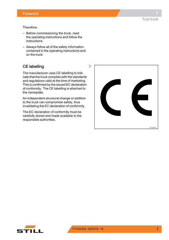
CE labellingThe manufacturer uses CE labelling to indi-cate that the truck complies with the standardsand regulations valid at the time of marketing.This is confirmed by the issued EC declarationof conformity. The CE labelling is attached tothe nameplate.
An independent structural change or additionto the truck can compromise safety, thusinvalidating the EC declaration of conformity.
The EC declaration of conformity must becarefully stored and made available to theresponsible authorities.
171533 EN - 02/2019 - 19 5
1 ForewordYour truck
EC declaration of conformity in accordance with Machinery Directive
Declaration
STILL GmbH
Berzeliusstraße 10
D-22113 Hamburg Germany
We declare that the
Industrial truck according to these operating instructions
Model according to these operating instructions
conforms to the latest version of the Machinery Directive 2006/42/EC.
Personnel authorised to compile the technical documents:
See EC compliance declaration
STILL GmbH
.
6 171533 EN - 02/2019 - 19

Foreword 1Your truck
Accessories• Key for key switch (2 pieces)• Key for cab (variant)• Hexagon socket wrench for emergencylowering
• Battery replacement frame
171533 EN - 02/2019 - 19 7
1 ForewordYour truck
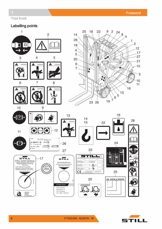
Labelling points
DANGER
STOP
12
3 4 5
6 7 8
910
11
1415 28
16
26
17
27
22
20
12
13
1926237
65
1316
3
15
21
122
1
2717
2
48
92214
18
28
1825
45
620
7
1011
24
5430 1010 1080 1080 1080
1050 1150 1310
4430 1110 1230 1250 1500
4030 1150 1260 1200 1500
3730 1180 1290 1430 1500
3430 1210 1330 1470 1500
800 700 500600
5030 1270
2
1
3
xx xxxx x xxxxx
1
2
3
4
24
25
STILL Hamburg
Berzeliusstr. 10
22113 Hamburg
Tel.: 01804 / 784 55 24
Ihr STILL Service
Nächste Prüfung
7339
06
BATTERIESERVICE
DANGER
23
Regelmäßige Prüfung(FEM 4.004)
nach nationalen Vorschriftenbasierend auf den EG-Richtlinien:95/63/EG, 99/92/EG, 2001/45/EG
Die Prüfplakette ersetzt nicht das Prüfprotokoll
Nächste Prüfung
5634
4391
019
Mitglied der:FédérationEuropéenede la Manutention
STILL GmbH Hamburg
20xx
Type-Modèle-Typ / Serial no.-No. de série-Serien-Nr. / year-année-Baujahr
Rated capacityCapacité nominaleNenn-Tragfähigkeit
Battery voltageTension batterieBatteriespannung
Rated drive powerPuissance motr.nom.Nenn-Antriebsleist.
Unladen massMasse à videLeergewicht
maxmin.*
* see Operating instructions voir Mode d'emploi siehe Betriebsanleitung
kg kg
kgkg
kgkW
V
*
D-22113 HamburgBerzeliusstr. 10
8 171533 EN - 02/2019 - 19
Foreword 1Your truck
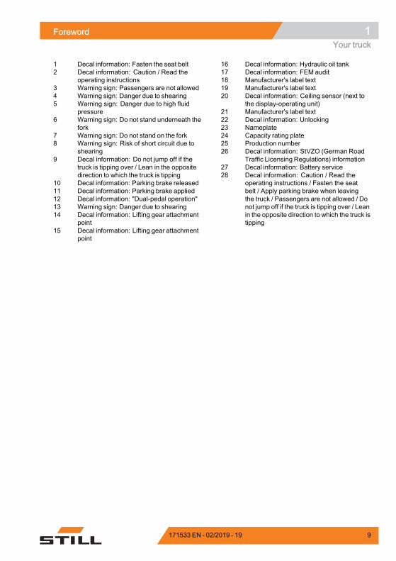
1 Decal information: Fasten the seat belt2 Decal information: Caution / Read the
operating instructions3 Warning sign: Passengers are not allowed4 Warning sign: Danger due to shearing5 Warning sign: Danger due to high fluid
pressure6 Warning sign: Do not stand underneath the
fork7 Warning sign: Do not stand on the fork8 Warning sign: Risk of short circuit due to
shearing9 Decal information: Do not jump off if the
truck is tipping over / Lean in the oppositedirection to which the truck is tipping
10 Decal information: Parking brake released11 Decal information: Parking brake applied12 Decal information: "Dual-pedal operation"13 Warning sign: Danger due to shearing14 Decal information: Lifting gear attachment
point15 Decal information: Lifting gear attachment
point
16 Decal information: Hydraulic oil tank17 Decal information: FEM audit18 Manufacturer's label text19 Manufacturer's label text20 Decal information: Ceiling sensor (next to
the display-operating unit)21 Manufacturer's label text22 Decal information: Unlocking23 Nameplate24 Capacity rating plate25 Production number26 Decal information: StVZO (German Road
Traffic Licensing Regulations) information27 Decal information: Battery service28 Decal information: Caution / Read the
operating instructions / Fasten the seatbelt / Apply parking brake when leavingthe truck / Passengers are not allowed / Donot jump off if the truck is tipping over / Leanin the opposite direction to which the truck istipping
171533 EN - 02/2019 - 19 9
1 ForewordYour truck
Type-Modèle-Typ / Serial no.-No. de série-Serien-Nr. / year-année-Baujahr
Rated capacityCapacité nominaleNenn-Tragfähigkeit
Battery voltageTension batterieBatteriespannung
Rated drive powerPuissance motr.nom.Nenn-Antriebsleist.
Unladen massMasse à videLeergewicht
maxmin.*
* see Operating instructions voir Mode d'emploi siehe Betriebsanleitung
kg kg
kgkg
kgkW
V
*
D-22113 HamburgBerzeliusstr. 10
1 2 3
44
56
7
910
111213
6210_921-003_V3
8
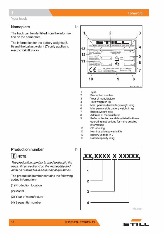
1 Type2 Production number3 Year of manufacture4 Tare weight in kg5 Max. permissible battery weight in kg6 Min. permissible battery weight in kg7 Ballast weight in kg8 Address of manufacturer9 Refer to the technical data listed in these
operating instructions for more detailedinformation
10 CE labelling11 Nominal drive power in kW12 Battery voltage in V13 Rated capacity in kg
NameplateThe truck can be identified from the informa-tion on the nameplate.
The information for the battery weights (5,6) and the ballast weight (7) only applies toelectric forklift trucks.
7090_921-004
xx xxxx x xxxxx
1
2
3
4
Production number
NOTE
The production number is used to identify thetruck. It can be found on the nameplate andmust be referred to in all technical questions.
The production number contains the followingcoded information:
(1) Production location
(2) Model
(3) Year of manufacture
(4) Sequential number
10 171533 EN - 02/2019 - 19
Foreword 1Using the truck
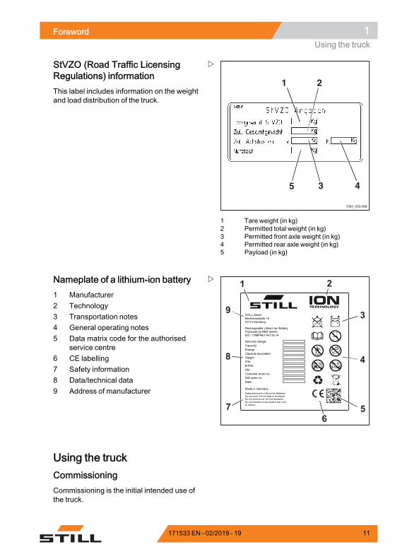
7094_003-098
1 2
3 45
1 Tare weight (in kg)2 Permitted total weight (in kg)3 Permitted front axle weight (in kg)4 Permitted rear axle weight (in kg)5 Payload (in kg)
StVZO (Road Traffic LicensingRegulations) informationThis label includes information on the weightand load distribution of the truck.
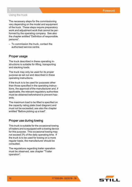
STILL GmbhBerzeliusstraße 1022113 Hamburg
Rechargeable Lithium Ion BatteryProduced by BMZ GmbHIEC: 13IMP46/174/133-14
Nominal voltage:Capacity:Energy:Capacity equivalent:Weight:P/N:B-P/N:SN:Custumer order no.:Still order no.:Date:
Made in GermanySafety Advices for Lithium-Ion BatteriesDo not crush. Do not heat or incinerate.Do not short-circuit. Do not dismantle.Do not immerse in any liquid it may ventor rupture.
9 3
4
5
1 2
67
8
Nameplate of a lithium-ion battery1 Manufacturer2 Technology3 Transportation notes4 General operating notes5 Data matrix code for the authorised
service centre6 CE labelling7 Safety information8 Data/technical data9 Address of manufacturer
Using the truckCommissioningCommissioning is the initial intended use ofthe truck.
171533 EN - 02/2019 - 19 11
1 ForewordUsing the truck
The necessary steps for the commissioningvary depending on the model and equipmentof the truck. These steps require preparatorywork and adjustment work that cannot be per-formed by the operating company. See alsothe chapter entitled "Definition of responsiblepersons".
– To commission the truck, contact theauthorised service centre.
Proper usageThe truck described in these operating in-structions is suitable for lifting, transportingand stacking loads.
The truck may only be used for its properpurpose as set out and described in theseoperating instructions.
If the truck is to be used for purposes otherthan those specified in the operating instruc-tions, the approval of the manufacturer and, ifapplicable, the relevant regulatory authoritiesmust be obtained beforehand to prevent haz-ards.
The maximum load to be lifted is specified onthe capacity rating plate (load diagram) andmust not be exceeded; see also the chapterentitled "Before picking up a load".
Proper use during towingThis truck is suitable for the occasional towingof trailers and is equippedwith a towing devicefor this purpose. This occasional towing maynot exceed 2% of the daily operating time. Ifthe truck is to be used for towing on a moreregular basis, the manufacturer should beconsulted.
The regulations regarding trailer operationmust be observed; see chapter "Traileroperation".
12 171533 EN - 02/2019 - 19
Foreword 1Using the truck
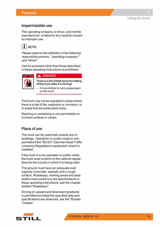
Impermissible useThe operating company or driver, and not themanufacturer, is liable for any hazards causedby improper use.
NOTE
Please observe the definition of the followingresponsible persons: "operating company"and "driver".
Use for purposes other than those describedin these operating instructions is prohibited.
DANGERThere is a risk of fatal injury from fallingoff the truck while it is moving!– It is prohibited to carry passengers
on the truck.
The truck may not be operated in areas wherethere is a risk of fire, explosion or corrosion, orin areas that are particularly dusty.
Stacking or unstacking is not permissible oninclined surfaces or ramps.
Place of useThe truck can be used both outside and inbuildings. Operation on public roads is onlypermitted if the "StVZO" (GermanRoad TrafficLicensing Regulations) equipment variant isinstalled.
If the truck is to be operated on public roads,the truck must conform to the national regula-tions for the country in which it is being used.
The ground must have an adequate loadcapacity (concrete, asphalt) and a roughsurface. Roadways, working areas and aislewidths must conform to the specifications inthese operating instructions; see the chapterentitled "Roadways".
Driving on upward and downward gradientsis permitted provided the specified data andspecifications are observed, see the "Routes"chapter.
171533 EN - 02/2019 - 19 13
1 ForewordUsing the truck
The truck is suitable for indoor and outdooruse in countries ranging from the Tropics toNordic regions (temperature range: -20°C to+40°C).
If the truck is to be used in a cold store, it mustbe configured accordingly and, if necessary,approved for such an environment; see thechapter entitled "Cold store application".
CAUTIONBatteries can freeze!If the truck is parked in an ambient temperature ofbelow -10°C for an extended period, the batterieswill cool down. The electrolyte may freeze anddamage the batteries. The truck is then not readyfor operation.– At ambient temperatures of below -10°C, only
park the truck for short periods of time.
The operating company must ensure suitablefire protection for the relevant application inthe truck's surroundings. Depending on theapplication, additional fire protection must beprovided on the truck. If in doubt, contact therelevant authorities.
NOTE
Please observe the definition of the followingresponsible person: "operating company".
Parking in temperatures below -10°C
CAUTIONBatteries can freeze!If the truck is parked in an ambient temperaturebelow -10°C for an extended period, the batterieswill cool down. The electrolyte may freeze anddamage the batteries. The truck is then not readyfor operation.– When the ambient temperature is below -10°C,
only park the truck for short periods of time.
14 171533 EN - 02/2019 - 19
Foreword 1Using the truck
Using working platforms
WARNINGThe use of working platforms is regulated by na-tional law. The use of working platforms is onlypermitted by virtue of the jurisdiction in the countryof use.– Observe national legislation.– Before using working platforms, consult the
national regulatory authorities.
171533 EN - 02/2019 - 19 15
1 ForewordInformation about the documentation
Information about the documentationDocumentation scope• Original operating instructions• Original operating instructions for attach-ments (variant)
• Spare parts list• Depending on the truck equipment, "UPA"operating instructionsmay also be provided
NOTE
Refer to the additional information in thesection entitled "Rules for the operatingcompany of industrial trucks".
These operating instructions describe allmeasures necessary for the safe operationand proper maintenance of the truck in allpossible variants available at the time ofprinting. Special versions to meet customerrequirements (UPA) are documented inseparate operating instructions. If you haveany questions, please contact your authorisedservice centre.
Enter the production number and year ofmanufacture from the nameplate in the spaceprovided:
Production number:
Year of manufacture:
Please quote the production number in alltechnical enquiries.
Each truck comes with a set of operatinginstructions. These instructions must bestored carefully and must be available to thedriver and operating company at all times.The storage location is specified in the chapterentitled "Overviews".
If the operating instructions are lost, the op-erating company must obtain a replacementfrom the manufacturer immediately.
The operating instructions are included in thespare parts list and can be reordered as aspare part.
16 171533 EN - 02/2019 - 19
Foreword 1Information about the documentation
The personnel responsible for operating andmaintaining the equipment must be familiarwith these operating instructions.
The operating company must ensure that allusers have received, read and understoodthese operating instructions.
Safely store the complete documentation andpass on to the subsequent operating companywhen transferring or selling the truck.
NOTE
Please observe the definition of the followingresponsible persons: "operating company"and "driver".
Thank you for reading and complying withthese operating instructions. If you have anyquestions or suggestions for improvements,or if you have found any errors, please contactthe authorised service centre.
Supplementary documentationThis industrial truck can be fitted with un-planned equipment (UPA) that deviates fromthe standard equipment and/or the variants.
The UPAmay be, for example:• Special sensors• Special attachments• Towing devices• Customised attachments
In this case, the industrial truck has additionaldocumentation. This may be in the form of aninsert or separate operating instructions.
The original operating instructions for thisindustrial truck are valid for the operationof standard equipment and variants withoutrestriction. The operational and safety infor-mation in the original operating instructionscontinues to be valid in its entirety unless it iscountermanded in this additional documenta-tion.
The requirements for the qualification ofpersonnel as well as the time for maintenance
171533 EN - 02/2019 - 19 17

1 ForewordInformation about the documentation
may vary. This is defined in the additionaldocumentation.
– If you have any questions, please contactyour authorised service centre.
Issue date and topicality of theoperating instructionsThe issue date of these operating instructionscan be found on the title page.
STILL is constantly engaged in the furtherdevelopment of trucks. These operatinginstructions are subject to change, and anyclaims based on the information and/orillustrations contained in them cannot beasserted.
Please contact your authorised service centrefor technical support relating to your truck.
Copyright and trademark rightsThese instructions must not be reproduced,translated or made accessible to third par-ties—including as excerpts—except with theexpress written approval of the manufacturer.
Explanation of information symbolsused
DANGERIndicates procedures that must be strictly adheredto in order to prevent the risk of fatalities.
WARNINGIndicates procedures that must be strictly adheredto in order to prevent the risk of injuries.
CAUTIONIndicates procedures that must be strictly adheredto in order to prevent material damage and/ordestruction.
18 171533 EN - 02/2019 - 19

Foreword 1Information about the documentation
NOTE
For technical requirements that requirespecial attention.
ENVIRONMENT NOTE
To prevent environmental damage.
List of abbreviations
NOTE
This list of abbreviations applies to all typesof operating instructions. Not all of the abbre-viations that are listed here will necessarilyappear in these operating instructions.
Abbrevi-ation
Meaning Explanation
ABE Display operating unit
ArbSchG Arbeitsschutzgesetz German implementation of EU occupa-tional health and safety directives
Betr-SichV
Betriebssicherheitsverordnung German implementation of the EU workingequipment directive
BG Berufsgenossenschaft German insurance company for the com-pany and employees
BGG Berufsgenossenschaftlicher Grundsatz German principles and test specificationsfor occupational health and safety
BGR Berufsgenossenschaftliche Regel German rules and recommendations foroccupational health and safety
DGUV Berufsgenossenschaftliche Vorschrift German accident prevention regulations
CE Communauté Européenne Confirms conformity with product-specificEuropean directives (CE mark)
CEECommission on the Rules for the Approvalof the Electrical Equipment
International commission on the rules forthe approval of electrical equipment
DC Direct Current Direct current
DFÜ Datenfernübertragung Remote data transmission
DIN Deutsches Institut für Normung German standardisation organisation
EG European Community
EN European standard
FEM Fédération Européene de la Manutention European Federation of Materials Han-dling and Storage Equipment
Fmax maximum Force Maximum power
171533 EN - 02/2019 - 19 19

1 ForewordInformation about the documentation
Abbrevi-ation
Meaning Explanation
GAA Gewerbeaufsichtsamt
German authority for monitoring/issuingregulations for worker protection, environ-mental protection, and consumer protec-tion
GPRS General Packet Radio Service Transfer of data packets in wirelessnetworks
ID no. ID number
ISO International Organization for Standard-ization
International standardisation organisation
LAN Local Area Network Local area network
KpAUncertainty of measurement of soundpressure levels
LED Light Emitting Diode Light emitting diode
Lp Sound pressure level at the workplace
LpAZAverage continuous sound pressure levelin the driver's compartment
LSP Load centre of gravity Distance of the centre of gravity of the loadfrom the front face of the fork backs
MAK Maximum workplace concentration Maximum permissible air concentrationsof a substance at the workplace
Max. Maximum Highest value of an amount
Min. Minimum Lowest value of an amount
PIN Personal Identification Number Personal identification numberPPE Personal protective equipment
SE Super-Elastic Superelastic tyres (solid rubber tyres)
SIT Snap-In Tyre Tyres for simplified assembly, withoutloose rim parts
StVZO Straßenverkehrs-Zulassungs-Ordnung German regulations for approval of vehi-cles on public roads
TRGS Technische Regel für Gefahrstoffe Ordinance on hazardous materials appli-cable in the Federal Republic of Germany
VDE Verband der Elektrotechnik ElektronikInformationstechnik German technical/scientific association
VDI Verein Deutscher Ingenieure German technical/scientific association
VDMAVerband Deutscher Maschinen- undAnlagenbau e.V.
German Mechanical Engineering IndustryAssociation
WLAN Wireless LAN Wireless local area network.
20 171533 EN - 02/2019 - 19
Foreword 1Information about the documentation
6210_001-031
4 2
3
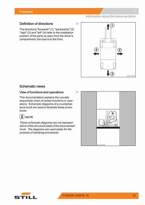
1Definition of directionsThe directions "forwards" (1), "backwards" (3),"right" (2) and "left" (4) refer to the installationposition of the parts as seen from the driver'scompartment; the load is to the front.
Schematic views
6210_003-062
View of functions and operationsThis documentation explains the (usuallysequential) chain of certain functions or oper-ations. Schematic diagrams of a counterbal-ance truck are used to illustrate these proce-dures.
NOTE
These schematic diagrams are not represen-tative of the structural state of the documentedtruck. The diagrams are used solely for thepurpose of clarifying procedures.
171533 EN - 02/2019 - 19 21
1 ForewordInformation about the documentation
View of the display operating unit
NOTE
Views of operating statuses and values inthe display of the display operating unit areexamples and partly dependent on the truckequipment. As a result, the displays shownof the actual operating statuses and valuescan vary. Information that is not relevant fordescriptions is not shown.
22 171533 EN - 02/2019 - 19
Foreword 1Environmental considerations
Environmental considerationsPackagingDuring delivery of the truck, certain partsare packaged to provide protection duringtransport. This packaging must be removedcompletely prior to initial start-up.
ENVIRONMENT NOTE
The packaging material must be disposed ofproperly after delivery of the truck.
Disposal of components andbatteriesThe truck is composed of different materials. Ifcomponents or batteries need to be replacedand disposed of, they must be:• disposed of,• treated or• recycled in accordance with regional andnational regulations.
NOTE
The documentation provided by the batterymanufacturer must be observed when dispo-sing of batteries.
ENVIRONMENT NOTE
We recommend working with a waste mana-gement company for disposal purposes.
171533 EN - 02/2019 - 19 23

1 ForewordEnvironmental considerations
24 171533 EN - 02/2019 - 19

2
Safety
2 SafetyDefinition of responsible persons
Definition of responsible personsOperating companyThe operating company is the natural or legalperson or group who operates the truck or onwhose authority the truck is used.
The operating company must ensure that thetruck is only used for its proper purpose and incompliance with the safety regulations set outin these operating instructions.
The operating company must ensure thatall users read and understand the safetyinformation.
The operating company is responsible for thescheduling and correct performance of regularsafety checks.
We recommend that the national performancespecifications are adhered to.
SpecialistA qualified person is defined as a serviceengineer or a person who fulfils the followingrequirements:• A completed vocational qualification thatdemonstrably proves their professionalexpertise. This proof should consist ofa vocational qualification or a similardocument.
• Professional experience indicating thatthe qualified person has gained practicalexperience of industrial trucks over aproven period during their career Duringthis time, this person has become familiarwith a wide range of symptoms that requirechecks to be carried out, such as basedon the results of a hazard assessment or adaily inspection
• Recent professional involvement in thefield of the industrial truck test in questionand an appropriate further qualificationare essential. The qualified person musthave experience of carrying out the testin question or of carrying out similar tests.Moreover, this person must be aware ofthe latest technological developments
26 171533 EN - 02/2019 - 19
Safety 2Definition of responsible persons
regarding the industrial truck to be testedand the risk being assessed
DriversThis truck may only be driven by suitable per-sons who are at least 18 years of age, havebeen trained in driving, have demonstratedtheir skills in driving and handling loads tothe operating company or an authorised rep-resentative, and have been specifically in-structed to drive the truck. Specific knowledgeof the truck to be operated is also required.
The training requirements under §3 of theHealth and Safety at Work Act and §9 of theplant safety regulations are deemed to havebeen satisfied if the driver has been trained inaccordance with BGG (General Employers'Liability Insurance Association Act) 925.Observe the national regulations for yourcountry.
Driver rights, duties and rules of be-haviourThe driver must be trained in his rights andduties.
The drivermust be granted the required rights.
The driver must wear protective equipment(protection suit, safety footwear, safetyhelmet, industrial goggles and gloves) thatis appropriate for the conditions, the job andthe load to be lifted. Solid footwear should beworn to ensure safe driving and braking.
The driver must be familiar with the operatinginstructions and have access to them at alltimes.
The driver must:• have read and understood the operatingmanual
• have familiarised himself with safe opera-tion of the truck
• be physically and mentally able to drive thetruck safely
171533 EN - 02/2019 - 19 27

2 SafetyDefinition of responsible persons
DANGERThe use of drugs, alcohol or medications that affectreactions impair the ability to drive the truck!Individuals under the influence of the aforementio-ned substances are not permitted to perform workof any kind on or with the truck.
Prohibition of use by unauthorisedpersonsThe driver is responsible for the truck duringworking hours. He must not allow unautho-rised persons to operate the truck.
When leaving the truck, the drivermust secureit against unauthorised use, e.g. by pulling outthe key.
28 171533 EN - 02/2019 - 19
Safety 2Basic principles for safe operation
Basic principles for safe operationInsurance cover on companypremisesIn many cases, company premises arerestricted public traffic areas.
NOTE
The business liability insurance should bereviewed to ensure that, in the event of anydamage caused in restricted public trafficareas, there is insurance cover for the truck inrespect of third parties.
171533 EN - 02/2019 - 19 29
2 SafetyBasic principles for safe operation
Special features when using lithium-ion batteries (variant)
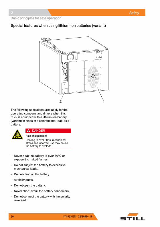
2 1
The following special features apply for theoperating company and drivers when thistruck is equipped with a lithium-ion battery(variant) in place of a conventional lead-acidbattery.
DANGERRisk of explosion!Heating to over 80°C, mechanicalstress and incorrect use may causethe battery to explode.
– Never heat the battery to over 80°C orexpose it to naked flames.
– Do not subject the battery to excessivemechanical loads.
– Do not climb on the battery.
– Avoid impacts.
– Do not open the battery.
– Never short-circuit the battery connectors.
– Do not connect the battery with the polarityreversed.
30 171533 EN - 02/2019 - 19
Safety 2Basic principles for safe operation
Product-specific dangers of the 36.2-kWh and 118.4-kWh lithium-ion battery
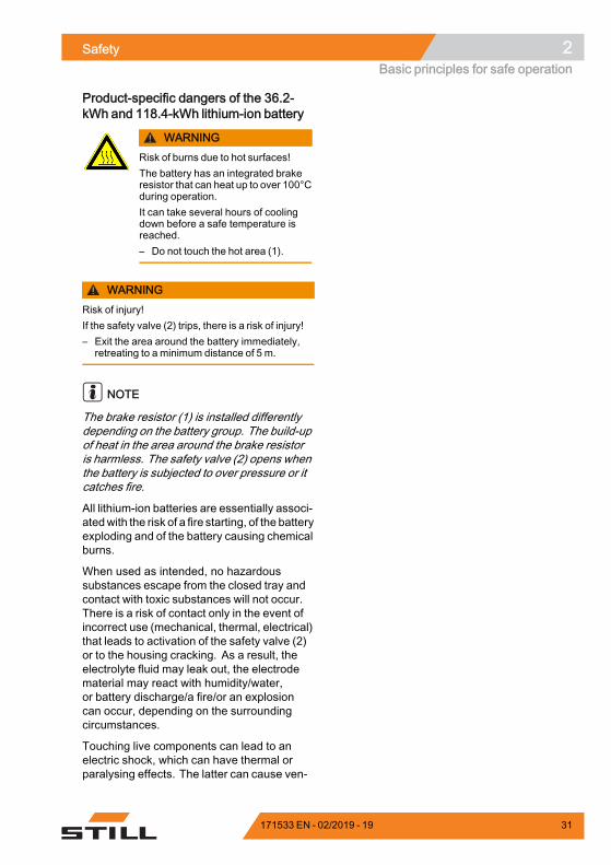
WARNINGRisk of burns due to hot surfaces!The battery has an integrated brakeresistor that can heat up to over 100°Cduring operation.It can take several hours of coolingdown before a safe temperature isreached.– Do not touch the hot area (1).
WARNINGRisk of injury!If the safety valve (2) trips, there is a risk of injury!– Exit the area around the battery immediately,
retreating to a minimum distance of 5 m.
NOTE
The brake resistor (1) is installed differentlydepending on the battery group. The build-upof heat in the area around the brake resistoris harmless. The safety valve (2) opens whenthe battery is subjected to over pressure or itcatches fire.
All lithium-ion batteries are essentially associ-atedwith the risk of a fire starting, of the batteryexploding and of the battery causing chemicalburns.
When used as intended, no hazardoussubstances escape from the closed tray andcontact with toxic substances will not occur.There is a risk of contact only in the event ofincorrect use (mechanical, thermal, electrical)that leads to activation of the safety valve (2)or to the housing cracking. As a result, theelectrolyte fluid may leak out, the electrodematerial may react with humidity/water,or battery discharge/a fire/or an explosioncan occur, depending on the surroundingcircumstances.
Touching live components can lead to anelectric shock, which can have thermal orparalysing effects. The latter can cause ven-
171533 EN - 02/2019 - 19 31
2 SafetyBasic principles for safe operation
tricular fibrillation, cardiac arrest or respiratoryparalysis, leading to death.
If a battery combusts, the resulting smoke orvapours can cause irritation of the eyes, theskin and the respiratory system.
Permissible lithium-ion batteries– Use only lithium-ion batteries that havebeen approved by STILL for use with thistruck.
– Contact the authorised service centreregarding this matter.
Declaring the use of lithium-ion batteriesWe recommend that the operating companyinforms the local fire brigade of the planneduse of trucks fitted with lithium-ion batteries.
The health and safety representative and theworkforce must also be informed that truckswith lithium-ion batteries are being used.
Hazard assessmentIn accordance with §3 of the German Ordi-nance on Industrial Safety and Health (Betr-SichV), the operating company is obliged toperform a separate hazard assessment in or-der to assess the risks posed to the companyby lithium-ion batteries.
– Observe the national regulations for thecountry in which the truck is being used.
Driver qualification
In addition to the prerequisites set out in thechapter entitled "Definition of responsiblepersons", in the section entitled "Driver",please observe the following:• The driver must be instructed in how tooperate the lithium-ion battery.
• Only trained drivers may drive these trucks.
Procedure in the event of a fireDamaged lithium-ion batteries pose an in-creased fire hazard. In the event of a fire,
32 171533 EN - 02/2019 - 19
Safety 2Basic principles for safe operation
large quantities of water are the best option tocool the battery.
– Evacuate the location of the fire as quicklyas possible.
– Ventilate the location of the fire well, as theresulting combustion gases are corrosive ifinhaled.
– Inform the fire brigade that lithium-ionbatteries are affected by the fire.
– Observe the information provided bythe battery manufacturer regarding theprocedure in the event of a fire.
Water can be used to cool down an incipientfire.
TransportingIn certain circumstances, transport of thelithium-ion battery outside the premises mayrequire a special transport container.
– Contact the authorised service centre formore information.
Changes and retrofittingIf the truck will be used for work that is notlisted in the directives or in these instructions,convert or retrofit the truck for this purposeas required. Any structural modification canimpair the handling and stability of the truck,and can result in accidents.
Any modifications that adversely affect thestability, the load capacity or the circumferen-tial view of the truck require written approvalfrom the manufacturer.
The following components may only bemodified with prior written approval from themanufacturer:• Brakes• Steering• Operating devices• Safety systems• Equipment variants• Attachments
171533 EN - 02/2019 - 19 33
2 SafetyBasic principles for safe operation
The truck may only be converted with writtenapproval from the manufacturer. If necessary,obtain approval from the relevant authorities.
We warn against the installation and useof restraint systems not approved by themanufacturer.
– Contact the authorised service centrebefore converting or retrofitting the truck.
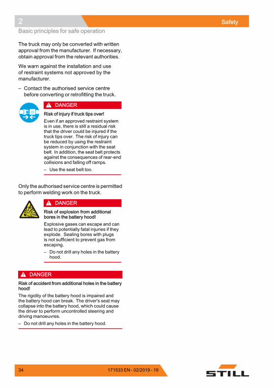
DANGERRisk of injury if truck tips over!Even if an approved restraint systemis in use, there is still a residual riskthat the driver could be injured if thetruck tips over. The risk of injury canbe reduced by using the restraintsystem in conjunction with the seatbelt. In addition, the seat belt protectsagainst the consequences of rear-endcollisions and falling off ramps.– Use the seat belt too.
Only the authorised service centre is permittedto perform welding work on the truck.
DANGERRisk of explosion from additionalbores in the battery hood!Explosive gases can escape and canlead to potentially fatal injuries if theyexplode. Sealing bores with plugsis not sufficient to prevent gas fromescaping.– Do not drill any holes in the battery
hood.
DANGERRisk of accident from additional holes in the batteryhood!The rigidity of the battery hood is impaired andthe battery hood can break. The driver's seat maycollapse into the battery hood, which could causethe driver to perform uncontrolled steering anddriving manoeuvres.– Do not drill any holes in the battery hood.
34 171533 EN - 02/2019 - 19
Safety 2Basic principles for safe operation
DANGERRisk to life from falling load!There is a risk to the driver's life if the truck is notequipped with an overhead guard, as the drivermay be struck by a load falling from a lift height of1800 mm or greater.Operation of the truck without an overhead guard isprohibited at a lift height greater than 1800 mm.– At lift heights of 1800 mm and above, only use
the truck in conjunction with an overhead guard.
The operating company is only permitted tomake modifications to the truck independentlyif the manufacturer goes into liquidation andthe company is not taken over by another legalperson.
The operating company must also fulfil thefollowing prerequisites:• Design documents, test documents andassembly instructions associated with themodification must be permanently archivedand remain accessible at all times.
• The capacity rating plate, the decal informa-tion, the hazard warnings and the operatinginstructions must be checked to ensure thatthey are consistent with the modificationsand must be amended if required.
• Modifications must be designed, checkedand implemented by a design office thatspecialises in industrial trucks. The designoffice must comply with the standards anddirectives valid at the time thatmodificationsare made.
Decal information with the following data mustbe permanently affixed to the truck so that it isclearly visible:• Type of modification• Date of modification• Name and address of the company thatcarried out the modification
171533 EN - 02/2019 - 19 35
2 SafetyBasic principles for safe operation
Changes to the overhead guard androof loads
DANGERIn the event of the overhead guard failing due toa falling load or the truck tipping over, there arepotentially fatal consequences for the driver. Thereis a risk to life!Welding and drilling on the overhead guard chan-ges the material characteristics and the structuraldesign of the overhead guard. Excessive forcescaused by falling loads or the truck tipping overmayresult in buckling of the modified overhead guardand no protection for the driver.– Do not perform welding on the overhead guard.– Do not perform drilling on the overhead guard.
CAUTIONHeavy roof loads damage the overhead guard!To ensure the stability of the overhead guard atall times, a roof load may only be mounted on theoverhead guard if the structural design has beentested and themanufacturer has given approval.– Seek advice from the authorised service centre
for the mounting of roof loads.
Warning regarding non-original partsOriginal parts, attachments and accessoriesare specially designed for this truck. Wespecifically draw your attention to the fact thatparts, attachments and accessories suppliedby other companies have not been tested andapproved by STILL.
CAUTIONInstallation and/or use of such products may there-fore have a negative impact on the design featuresof the truck and thus impair active and/or passivedriving safety.We recommend that you obtain approval from themanufacturer and, if necessary, from the relevantregulatory authorities before installing such parts.The manufacturer accepts no liability for any da-mage caused by the use of non-original parts andaccessories without approval.
36 171533 EN - 02/2019 - 19
Safety 2Basic principles for safe operation
Damage, defects and misuse ofsafety systemsDamage or other defects on the truck orattachment must be reported to the supervisoror responsible fleet manager immediately sothat they can have the defect rectified.
Trucks and attachments that are not functionalor safe to drivemay not be used until they havebeen properly repaired.
Do not remove or deactivate safety systemsand switches.
Fixed set valuesmay only be changedwith theapproval of the manufacturer.
Work on the electrical system (e.g. connectinga radio, additional headlights etc.) is onlypermitted with the manufacturer's writtenapproval. All electrical system interventionsmust be documented.
Even if they are removable, roof panels maynot be removed, as they are designed toprotect against small falling objects.
Tyres
DANGERRisk to stability!Failure to observe the following information andinstructions can lead to a loss of stability. The truckmay tip over, risk of accident!
The following factors can lead to a loss ofstability and are therefore prohibited:• Different tyres on the same axle, e.g.pneumatic tyres and superelastic tyres
• Tyres not approved by the manufacturer• Excessive tyre wear• Tyres of inferior quality• Changing rim wheel parts• Combining rim wheel parts from differentmanufacturers
171533 EN - 02/2019 - 19 37
2 SafetyBasic principles for safe operation
The following rules must be observed toensure stability:• Only use tyres with equal and permittedlevels of wear on the same axle
• Only use wheels and tyres of the same typeon the same axle, e.g. only superelastictyres
• Only use wheels and tyres approved by themanufacturer
• Only use high-quality products
Wheels and tyres approved by the manu-facturer can be found on the spare parts list.If other wheels or tyres are to be used, au-thorisation from the manufacturer must beobtained beforehand.
– Contact the authorised service centre onthis matter.
When changing wheels or tyres, alwaysensure that this does not cause the truck totilt to one side (e.g. always replace right-hand and left-hand wheels at the sametime). Changes must only be made followingconsultation with the manufacturer.
If the type of tyre used on an axle is changed,for example from superelastic tyres to pneu-matic tyres, the loaddiagrammust be changedaccordingly.
– Contact the authorised service centre onthis matter.
Medical equipment
WARNINGElectromagnetic interferencemayoccur onmedicaldevices!Only use equipment that is sufficiently protectedagainst electromagnetic interference.
Medical equipment, such as pacemakers orhearing aids, may not work properly when thetruck is in operation.
– Ask your doctor or the manufacturer ofthe medical equipment to confirm that themedical equipment is sufficiently protectedagainst electromagnetic interference.
38 171533 EN - 02/2019 - 19
Safety 2Basic principles for safe operation
Exercise caution when handling gassprings and accumulators
WARNINGGas springs are under high pressure. Improperremoval results in an elevated risk of injury.For ease of operation, various functions on thetruck can be supported by gas springs. Gas springsare complex components that are subject to highinternal pressures (up to 300 bar). They may underno circumstances be opened unless instructed todo so, and may be installed only when not underpressure. If required, the authorised service centrewill depressurise the gas spring in accordance withthe regulations before removal. Gas springs mustbe depressurised before recycling.– Avoid damage, lateral forces, buckling, tempe-
ratures over 80°C and heavy contamination.– Damaged or defective gas springs must be
changed immediately.– Contact the authorised service centre.
WARNINGAccumulators are under high pressure. Improperinstallation of an accumulator results in an elevatedrisk of injury.Before starting work on the accumulator it must bedepressurised.– Contact the authorised service centre.
Length of the fork arms
DANGERRisk of accident due to the incorrect selection offork arms!– The fork armsmust match the depth of the load.
If the fork arms are too short, the load mayfall off the arms after it has been picked up.In addition, be aware that the load centre ofgravity may shift as a result of dynamic forces,such as braking. A load that is otherwiseresting safely on the fork arms may moveforwards and fall.
If the fork arms are too long, they can catchon loading units behind the load that is to be
171533 EN - 02/2019 - 19 39

2 SafetyBasic principles for safe operation
picked up. These other loading units then fallover when the load is raised.
– For helpwith selecting the correct fork arms,contact the authorised service centre.
40 171533 EN - 02/2019 - 19

Safety 2Residual risk
Residual riskResidual dangers, residual risksDespite careful working and compliance withstandards and regulations, the occurrenceof other risks when using the truck cannot beentirely excluded.
The truck and all other system componentscomply with current safety requirements.Nevertheless, even when the truck is usedfor its proper purpose and all instructionsare followed, some residual risk cannot beexcluded.
Even beyond the narrow danger areas of thetruck itself, a residual risk cannot be excluded.Persons in this area around the truck mustexercise a heightened degree of awareness,so that they can react immediately in the eventof any malfunction, incident or breakdown etc.
WARNINGAll persons that are in the vicinity of the truckmust be instructed regarding these risks that arisethrough use of the truck.In addition, we draw attention to the safety regulati-ons in these operating instructions.
Risks can include:• Escape of consumables due to leakages,rupture of lines and containers etc.
• Risk of accident when driving over difficultground such as gradients, smooth orirregular surfaces, or with poor visibilityetc.
• Falling, tripping etc. when moving onthe truck, especially in wet weather, withleaking consumables or on icy surfaces
• Fire and explosion risks due to batteries andelectrical voltages
• Human error resulting from failure toobserve the safety regulations,
• Unrepaired damage or defective and worncomponents,
• Insufficient maintenance and testing• Use of incorrect consumables• Exceeding test intervals
171533 EN - 02/2019 - 19 41
2 SafetyResidual risk
The manufacturer is not held responsible foraccidents involving the truck caused by thefailure of the operating company to complywith these regulations either intentionally orcarelessly.
StabilityThe stability of the truck has been tested to thelatest technological standards and is guaran-teed provided that the truck is used properlyand according to its intended purpose. Thesestandards only take into account the dynamicand static tipping forces that can arise duringspecified use in accordance with the operat-ing rules and intended purpose. However, thedanger of exceeding the moment of tilt due toimproper use or incorrect operation and losingstability can never be excluded.
The loss of stability can be avoided or min-imised by the following actions:
– Always secure the load against slipping,e.g. by lashing.
– Always transport unstable loads in suitablecontainers.
– Always drive slowly when cornering.
– Drive with the load lowered.
– Even with sideshifts, align the load ascentrally as possible with the truck andtransport in this position.
– Avoid turning and diagonally driving acrossslopes or gradients.
– Never have the load facing downhill whentravelling on slopes or gradients.
– Pick up only loads of the approved width.
– Always take great care when transportingsuspended loads.
– Do not drive over ramp edges or steps.
Special risks associated with usingthe truck and attachmentsApproval from the manufacturer and attach-ment manufacturer must be obtained each
42 171533 EN - 02/2019 - 19
Safety 2Residual risk
time the truck is used in a manner that fallsoutside the scope of normal use, and in caseswhere the driver is not certain that he can usethe truck correctly and without the risk of acci-dents.
171533 EN - 02/2019 - 19 43
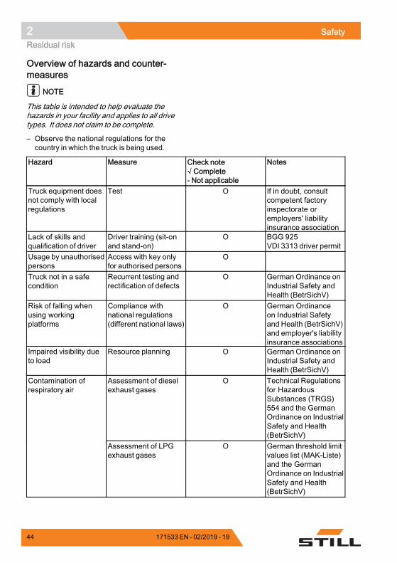
2 SafetyResidual risk
Overview of hazards and counter-measures
NOTE
This table is intended to help evaluate thehazards in your facility and applies to all drivetypes. It does not claim to be complete.
– Observe the national regulations for thecountry in which the truck is being used.
Hazard Measure Check note√ Complete- Not applicable
Notes
Truck equipment doesnot comply with localregulations
Test O If in doubt, consultcompetent factoryinspectorate oremployers' liabilityinsurance association
Lack of skills andqualification of driver
Driver training (sit-onand stand-on)
O BGG 925VDI 3313 driver permit
Usage by unauthorisedpersons
Access with key onlyfor authorised persons
O
Truck not in a safecondition
Recurrent testing andrectification of defects
O German Ordinance onIndustrial Safety andHealth (BetrSichV)
Risk of falling whenusing workingplatforms
Compliance withnational regulations(different national laws)
O German Ordinanceon Industrial Safetyand Health (BetrSichV)and employer's liabilityinsurance associations
Impaired visibility dueto load
Resource planning O German Ordinance onIndustrial Safety andHealth (BetrSichV)
Assessment of dieselexhaust gases
O Technical Regulationsfor HazardousSubstances (TRGS)554 and the GermanOrdinance on IndustrialSafety and Health(BetrSichV)
Contamination ofrespiratory air
Assessment of LPGexhaust gases
O German threshold limitvalues list (MAK-Liste)and the GermanOrdinance on IndustrialSafety and Health(BetrSichV)
44 171533 EN - 02/2019 - 19
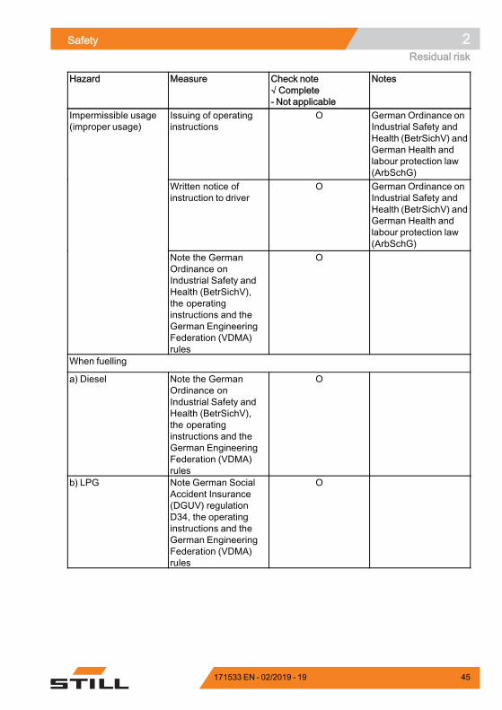
Safety 2Residual risk
Hazard Measure Check note√ Complete- Not applicable
Notes
Issuing of operatinginstructions
O German Ordinance onIndustrial Safety andHealth (BetrSichV) andGerman Health andlabour protection law(ArbSchG)
Written notice ofinstruction to driver
O German Ordinance onIndustrial Safety andHealth (BetrSichV) andGerman Health andlabour protection law(ArbSchG)
Impermissible usage(improper usage)
Note the GermanOrdinance onIndustrial Safety andHealth (BetrSichV),the operatinginstructions and theGerman EngineeringFederation (VDMA)rules
O
When fuelling
a) Diesel Note the GermanOrdinance onIndustrial Safety andHealth (BetrSichV),the operatinginstructions and theGerman EngineeringFederation (VDMA)rules
O
b) LPG Note German SocialAccident Insurance(DGUV) regulationD34, the operatinginstructions and theGerman EngineeringFederation (VDMA)rules
O
171533 EN - 02/2019 - 19 45
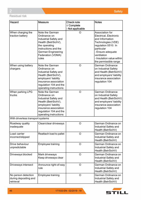
2 SafetyResidual risk
Hazard Measure Check note√ Complete- Not applicable
Notes
When charging thetraction battery
Note the GermanOrdinance onIndustrial Safety andHealth (BetrSichV),the operatinginstructions and theGerman EngineeringFederation (VDMA)rules
O Association forElectrical, Electronicand InformationTechnologies (VDE)regulation 0510: Inparticular- Ensure adequateventilation- Insulation value withinthe permissible range
When using batterychargers
Note the GermanOrdinance onIndustrial Safety andHealth (BetrSichV),employers' liabilityinsurance associationregulation 104 and theoperating instructions
O German Ordinanceon Industrial Safetyand Health (BetrSichV)and employers' liabilityinsurance associationregulation 104
When parking LPGtrucks
Note the GermanOrdinance onIndustrial Safety andHealth (BetrSichV),employers' liabilityinsurance associationregulation 104 and theoperating instructions
O German Ordinanceon Industrial Safetyand Health (BetrSichV)and employers' liabilityinsurance associationregulation 104
With driverless transport systems
Roadway qualityinadequate
Clean/clear driveways O German Ordinance onIndustrial Safety andHealth (BetrSichV)
Load carrierincorrect/slipped
Reattach load to pallet O German Ordinance onIndustrial Safety andHealth (BetrSichV)
Drive behaviourunpredictable
Employee training O German Ordinance onIndustrial Safety andHealth (BetrSichV)
Driveways blocked Mark drivewaysKeep driveways clear
O German Ordinance onIndustrial Safety andHealth (BetrSichV)
Driveways intersect Announce right-of-wayrule
O German Ordinance onIndustrial Safety andHealth (BetrSichV)
No person detectionduring depositing andretrieval
Employee training O German Ordinance onIndustrial Safety andHealth (BetrSichV)
.
46 171533 EN - 02/2019 - 19
Safety 2Residual risk
Danger to employeesAccording to the GermanOrdinance on Indus-trial Safety and Health (BetrSichV) and labourprotection law (ArbSchG), the operating com-pany must determine and assess hazardsduring operation, and establish the labourprotection measures required for employ-ees (BetrSichVO). The operating companymust therefore draw up appropriate operatinginstructions (§ 6 ArbSchG) and make themavailable to the driver. A responsible personmust be appointed.
NOTE
Please observe the definition of the followingresponsible persons: "operating company"and "driver".
The construction and equipment of thetruck correspond to the Machinery Directive2006/42/EC and are therefore marked withCE labelling. These elements are thereforenot included in the hazard assessment. At-tachments possess their own CE labelling andlikewise are not included for that reason. Theoperating company must, however, select thetype and equipment of the trucks so as to com-ply with the local provisions for deployment.
The result must be documented (§ 6 Arb-SchG). In the case of truck applications involv-ing similar hazard situations, the results maybe summarised. This overview (see chapter"Overview of hazards and countermeasures")provides help on complying with this regula-tion. The overview specifies the main hazardsthat are the most frequent cause of accidentsin the event of non-compliance. If other majoroperational hazards are involved, they mustalso be taken into consideration.
The conditions of use for trucks are broadlysimilar in many plants, so the hazards canbe summarised in one overview. Observethe information provided by the relevantemployers' liability insurance association onthis subject.
171533 EN - 02/2019 - 19 47
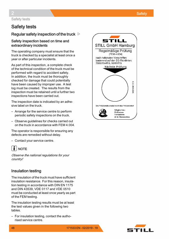
2 SafetySafety tests
Safety testsRegular safety inspection of the truck
Safety inspection based on time andextraordinary incidentsThe operating company must ensure that thetruck is checked by a specialist at least once ayear or after particular incidents.
As part of this inspection, a complete checkof the technical condition of the truck must beperformed with regard to accident safety.In addition, the truck must be thoroughlychecked for damage that could potentiallyhave been caused by improper use. A testlog must be created. The results from theinspection must be retained until a further twoinspections have been carried out.
The inspection date is indicated by an adhe-sive label on the truck.
– Arrange for the service centre to performperiodic safety inspections on the truck.
– Observe guidelines for checks carried outon the truck in accordance with FEM 4.004.
The operator is responsible for ensuring anydefects are remedied without delay.
– Contact your service centre.
NOTE
Observe the national regulations for yourcountry!
Insulation testingThe insulation of the truckmust have sufficientinsulation resistance. For this reason, insula-tion testing in accordance with DIN EN 1175and DIN 43539, VDE 0117 and VDE 0510must be conducted at least once yearly as partof the FEM testing.
The insulation testing results must be at leastthe test values given in the following twotables.
– For insulation testing, contact the autho-rised service centre.
48 171533 EN - 02/2019 - 19
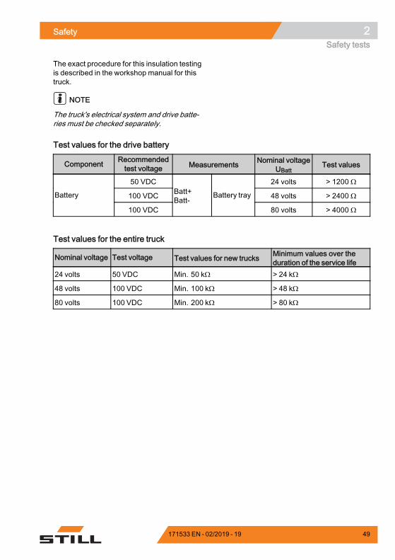
Safety 2Safety tests
The exact procedure for this insulation testingis described in the workshop manual for thistruck.
NOTE
The truck's electrical system and drive batte-ries must be checked separately.
Test values for the drive battery
Component Recommendedtest voltage Measurements Nominal voltage
UBattTest values
50 VDC 24 volts > 1200 Ω
100 VDC 48 volts > 2400 ΩBattery
100 VDC
Batt+Batt-
Battery tray
80 volts > 4000 Ω.
Test values for the entire truck
Nominal voltage Test voltage Test values for new trucks Minimum values over theduration of the service life
24 volts 50 VDC Min. 50 kΩ > 24 kΩ
48 volts 100 VDC Min. 100 kΩ > 48 kΩ
80 volts 100 VDC Min. 200 kΩ > 80 kΩ.
171533 EN - 02/2019 - 19 49
2 SafetySafety regulations for handling consumables
Safety regulations for handling consumablesPermissible consumables
DANGERFailure to observe the safety regulations relating toconsumables may result in a risk of injury, death ordamage to the environment.– Observe the safety regulations when handling
such materials.
Refer to the maintenance data table for thepermissible substances that are necessary foroperation (see ⇒ Chapter "Maintenance datatable", P. 5-387).
Oils
DANGEROils are flammable!– Follow the statutory regulations.– Do not allow oils to come into
contact with hot engine parts.– No smoking, fires or naked flames!
DANGEROils are toxic!– Avoid contact and consumption.– If vapour or fumes are inhaled,
move to fresh air immediately.– In the event of contact with the
eyes, rinse thoroughly (for at least10 minutes) with water and thenconsult an eye specialist.
– If swallowed, do not inducevomiting. Seek immediate medicalattention.
50 171533 EN - 02/2019 - 19
Safety 2Safety regulations for handling consumables
WARNINGProlonged intensive contact with theskin can result in dryness and irritatethe skin!– Avoid contact and consumption.– Wear protective gloves.– After any contact, wash the skin
with soap andwater, and then applya skin care product.
– Immediately change soakedclothing and shoes.
WARNINGThere is a risk of slipping on spilled oil, particularlywhen combined with water!– Spilt oil should be removed immediately with
oil-binding agents and disposed of according tothe regulations.
ENVIRONMENT NOTE
Oil is a water-polluting substance!• Always store oil in containers that complywith the applicable regulations.
• Avoid spilling oils.• Spilt oil should be removed immediatelywith oil-binding agents and disposed ofaccording to the regulations.
• Dispose of old oils according to the regula-tions.
Hydraulic fluid
WARNINGThese fluids are pressurised duringoperation of the truck and are hazar-dous to your health.– Do not spill the fluids.– Follow the statutory regulations.– Do not allow the fluids to come into
contact with hot engine parts.
171533 EN - 02/2019 - 19 51
2 SafetySafety regulations for handling consumables
WARNINGThese fluids are pressurised duringoperation of the truck and are hazar-dous to your health.– Do not allow the fluids to come into
contact with the skin.– Avoid inhaling spray.– Penetration of pressurised fluids
into the skin is particularly danger-ous if these fluids escape at highpressure due to leaks in the hydrau-lic system. In case of such injury,immediate medical assistance isrequired.
– To avoid injury, use appropriatepersonal protective equipment(e.g. protective gloves, industrialgoggles, skin protection and skincare products).
ENVIRONMENT NOTE
Hydraulic fluid is a water-polluting substance.• Always store hydraulic fluid in containersthat comply with regulations
• Avoid spills• Spilt hydraulic fluid should be removedimmediately with oil-binding agents anddisposed of according to the regulations
• Dispose of old hydraulic fluid according tothe regulations
Battery acid
WARNINGBattery acid contains dissolvedsulphuric acid. This is toxic.– Avoid touching or swallowing the
battery acid at all costs.– In case of injury, seek medical
advice immediately.
52 171533 EN - 02/2019 - 19

Safety 2Safety regulations for handling consumables
WARNINGBattery acid contains dissolvedsulphuric acid. This is corrosive.– When working with battery acid,
use appropriate PSA (rubbergloves, apron, protection goggles).
– When working with battery acid,never wear a watch or jewellery.
– Do not allow any acid to getonto clothing or skin or into theeyes. If this does happen, rinseimmediately with plenty of cleanwater.
– In case of injury, seek medicaladvice immediately.
– Immediately rinse away spiltbattery acid with plenty of water.
– Follow the statutory regulations.
ENVIRONMENT NOTE
– Dispose of used battery acid in line with theapplicable regulations.
Disposal of consumables
ENVIRONMENT NOTE
Materials that accumulate during repair,maintenance and cleaning must be collectedproperly and disposed of in accordance withthe national regulations for the country inwhich the truck is being used. Work mustonly be carried out in areas designated for thatpurpose. Care must be taken to minimise anyenvironmental pollution.
– Soak up any spilt fluids such as hydraulicoil or gearbox oil immediately using anoil-binding agent.
– Neutralise any spilt battery acid immedi-ately.
– Always observe national regulations con-cerning the disposal of used oil.
171533 EN - 02/2019 - 19 53
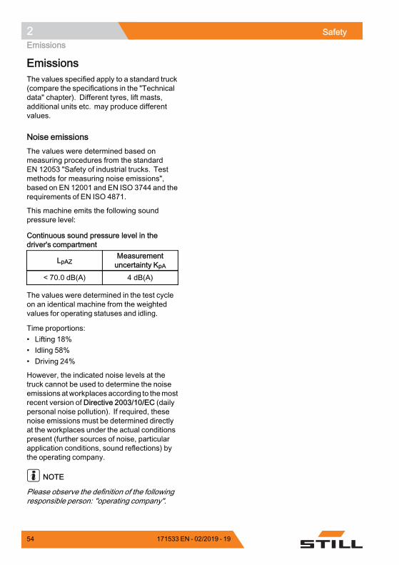
2 SafetyEmissions
EmissionsThe values specified apply to a standard truck(compare the specifications in the "Technicaldata" chapter). Different tyres, lift masts,additional units etc. may produce differentvalues.
Noise emissionsThe values were determined based onmeasuring procedures from the standardEN 12053 "Safety of industrial trucks. Testmethods for measuring noise emissions",based on EN 12001 and EN ISO 3744 and therequirements of EN ISO 4871.
This machine emits the following soundpressure level:
Continuous sound pressure level in thedriver's compartment
LpAZMeasurementuncertainty KpA
< 70.0 dB(A) 4 dB(A)
The values were determined in the test cycleon an identical machine from the weightedvalues for operating statuses and idling.
Time proportions:• Lifting 18%• Idling 58%• Driving 24%
However, the indicated noise levels at thetruck cannot be used to determine the noiseemissions atworkplacesaccording to themostrecent version of Directive 2003/10/EC (dailypersonal noise pollution). If required, thesenoise emissions must be determined directlyat the workplaces under the actual conditionspresent (further sources of noise, particularapplication conditions, sound reflections) bythe operating company.
NOTE
Please observe the definition of the followingresponsible person: "operating company".
54 171533 EN - 02/2019 - 19
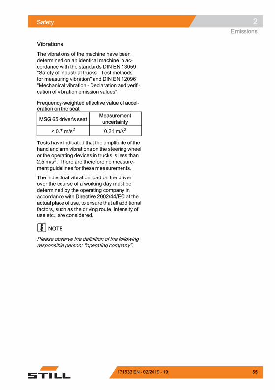
Safety 2Emissions
VibrationsThe vibrations of the machine have beendetermined on an identical machine in ac-cordance with the standards DIN EN 13059"Safety of industrial trucks - Test methodsfor measuring vibration" and DIN EN 12096"Mechanical vibration - Declaration and verifi-cation of vibration emission values".
Frequency-weighted effective value of accel-eration on the seat
MSG 65 driver's seatMeasurementuncertainty
< 0.7 m/s2 0.21 m/s2
Tests have indicated that the amplitude of thehand and arm vibrations on the steering wheelor the operating devices in trucks is less than2.5 m/s2. There are therefore no measure-ment guidelines for these measurements.
The individual vibration load on the driverover the course of a working day must bedetermined by the operating company inaccordance with Directive 2002/44/EC at theactual place of use, to ensure that all additionalfactors, such as the driving route, intensity ofuse etc., are considered.
NOTE
Please observe the definition of the followingresponsible person: "operating company".
171533 EN - 02/2019 - 19 55
2 SafetyEmissions
Battery
DANGERRisk of explosion due to flammablegases!During charging, the lead-acid batteryreleases a mixture of oxygen andhydrogen (oxyhydrogen gas). Thisgas mixture is explosive and must notbe ignited.– Make sure that there is always
sufficient ventilation in workingareas that are entirely or partiallyenclosed.
– Keep away from open flames andflying sparks.
– Do not smoke.– Observe the instructions in the
chapter entitled Safety regulationswhen handling the battery.
RadiationAccording to the guide-lines DIN EN 62471:2009-03(VDE 0837-471:2009-03), the STILL Safety-Light (variant) is assigned to risk group 2 dueto its photobiological hazard potential.
56 171533 EN - 02/2019 - 19

3
Overviews
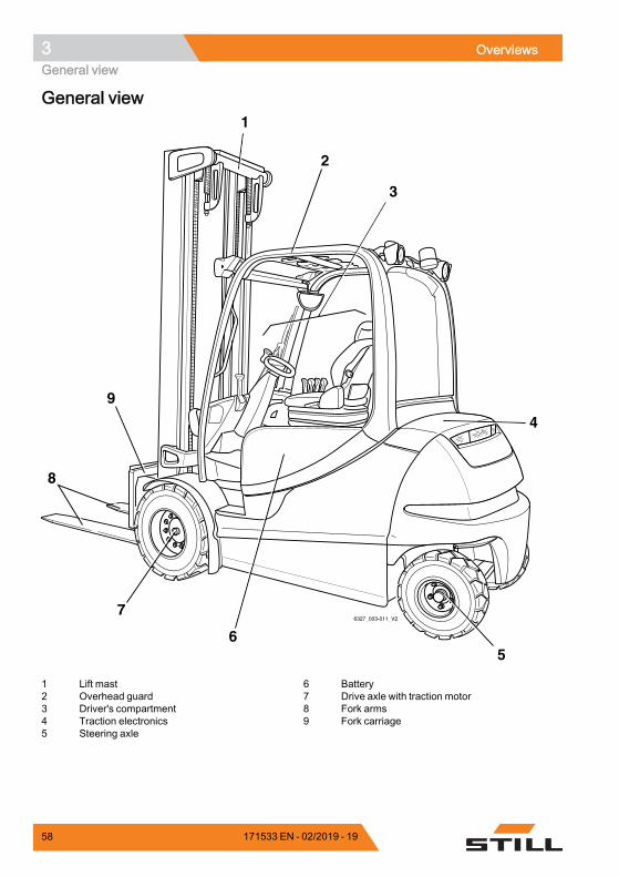
3 OverviewsGeneral view
General view
56
7
8
9
1
2
3
4
6327_003-011_V2
1 Lift mast2 Overhead guard3 Driver's compartment4 Traction electronics5 Steering axle
6 Battery7 Drive axle with traction motor8 Fork arms9 Fork carriage
58 171533 EN - 02/2019 - 19

Overviews 3General view
171533 EN - 02/2019 - 19 59
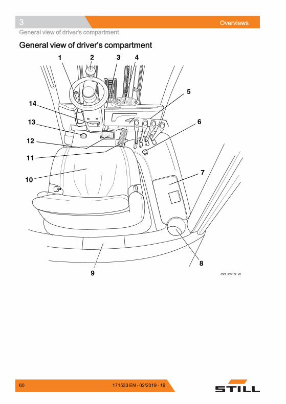
3 OverviewsGeneral view of driver's compartment
General view of driver's compartment
8
9
6
72
0
13
5
%75
h
2
234,7
12:15
1 2 3 4
5
6
7
89
10
11
12
13
14
6321_003-132_V3
60 171533 EN - 02/2019 - 19
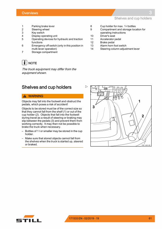
Overviews 3Shelves and cup holders
1 Parking brake lever2 Steering wheel3 Key switch4 Display operating unit5 Operating devices for hydraulic and traction
functions6 Emergency off switch (only in this position in
multi-lever operation)7 Storage compartment
8 Cup holder for max. 1-l bottles9 Compartment and storage location for
operating instructions10 Driver's seat11 Accelerator pedal12 Brake pedal13 Alarm horn foot switch14 Steering column adjustment lever
NOTE
The truck equipment may differ from theequipment shown.
7321_003-125
1
2
3
Shelves and cup holders
WARNINGObjects may fall into the footwell and obstruct thepedals, which poses a risk of accident!Objects to be stored must be of the correct size sothat they cannot fall from the shelf (1) or out of thecup holder (2). Objects that fall into the footwellduring travel as a result of steering or braking mayslip between the pedals (3) and prevent them fromworking correctly. It may then not be possible tobrake the truck when necessary.– Bottles of 1 l or smaller may be stored in the cup
holder.– Make sure that stored objects cannot fall from
the shelves when the truck is started up, steeredor braked.
171533 EN - 02/2019 - 19 61
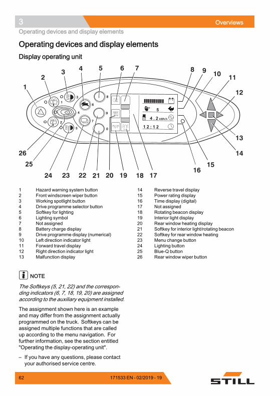
3 OverviewsOperating devices and display elements
Operating devices and display elementsDisplay operating unit
4
12
3 4 5 6 7 8 9 10 11
12
13
14
1516
1718192021222324
26
25
1 Hazard warning system button2 Front windscreen wiper button3 Working spotlight button4 Drive programme selector button5 Softkey for lighting6 Lighting symbol7 Not assigned8 Battery charge display9 Drive programme display (numerical)10 Left direction indicator light11 Forward travel display12 Right direction indicator light13 Malfunction display
14 Reverse travel display15 Power rating display16 Time display (digital)17 Not assigned18 Rotating beacon display19 Interior light display20 Rear window heating display21 Softkey for interior light/rotating beacon22 Softkey for rear window heating23 Menu change button24 Lighting button25 Blue-Q button26 Rear window wiper button
NOTE
The Softkeys (5, 21, 22) and the correspon-ding indicators (6, 7, 18, 19, 20) are assignedaccording to the auxiliary equipment installed.
The assignment shown here is an exampleand may differ from the assignment actuallyprogrammed on the truck. Softkeys can beassigned multiple functions that are calledup according to the menu navigation. Forfurther information, see the section entitled"Operating the display-operating unit".
– If you have any questions, please contactyour authorised service centre.
62 171533 EN - 02/2019 - 19
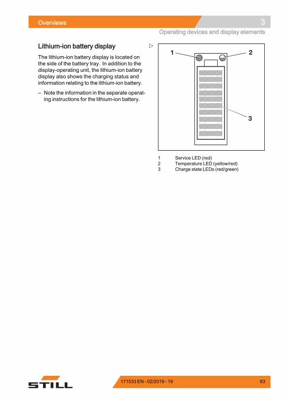
Overviews 3Operating devices and display elements
1 2
3
1 Service LED (red)2 Temperature LED (yellow/red)3 Charge state LEDs (red/green)
Lithium-ion battery displayThe lithium-ion battery display is located onthe side of the battery tray. In addition to thedisplay-operating unit, the lithium-ion batterydisplay also shows the charging status andinformation relating to the lithium-ion battery.
– Note the information in the separate operat-ing instructions for the lithium-ion battery.
171533 EN - 02/2019 - 19 63
3 OverviewsOperating devices and display elements
Operating devices for hydraulic andtraction functionsDifferent versions of the operating devices areavailable for operating the truck's hydraulicand traction functions.
The truck can be equipped with the followingoperating devices:• Multiple-lever• Double mini-lever• Triple mini-lever• Quadruple mini-lever• Joystick 4Plus• Fingertip• Mini-console
64 171533 EN - 02/2019 - 19
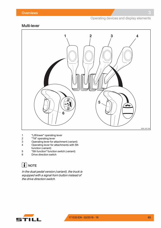
Overviews 3Operating devices and display elements
Multi-lever
5060_003-168
1 2 3 4
5
6
1 "Lift/lower" operating lever2 "Tilt" operating lever3 Operating lever for attachment (variant)4 Operating lever for attachments with 5th
function (variant)5 "5th function" function switch (variant)6 Drive direction switch
NOTE
In the dual-pedal version (variant), the truck isequipped with a signal horn button instead ofthe drive direction switch.
171533 EN - 02/2019 - 19 65
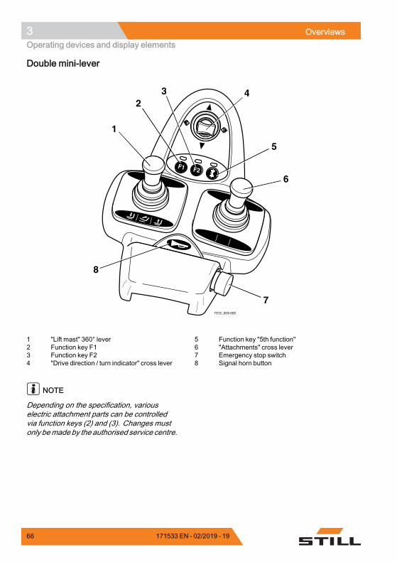
3 OverviewsOperating devices and display elements
Double mini-lever
F1 F2
7312_003-002
1
23 4
5
6
7
8
1 "Lift mast" 360° lever2 Function key F13 Function key F24 "Drive direction / turn indicator" cross lever
5 Function key "5th function"6 "Attachments" cross lever7 Emergency stop switch8 Signal horn button
NOTE
Depending on the specification, variouselectric attachment parts can be controlledvia function keys (2) and (3). Changes mustonly bemade by the authorised service centre.
66 171533 EN - 02/2019 - 19
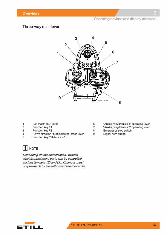
Overviews 3Operating devices and display elements
Three-way mini-lever
1
2
3 45
6
7
89
5060_003-089
1 "Lift mast" 360° lever2 Function key F13 Function key F24 "Drive direction / turn indicator" cross lever5 Function key "5th function"
6 "Auxiliary hydraulics 1" operating lever7 "Auxiliary hydraulics 2" operating lever8 Emergency stop switch9 Signal horn button
NOTE
Depending on the specification, variouselectric attachment parts can be controlledvia function keys (2) and (3). Changes mustonly bemade by the authorised service centre.
171533 EN - 02/2019 - 19 67
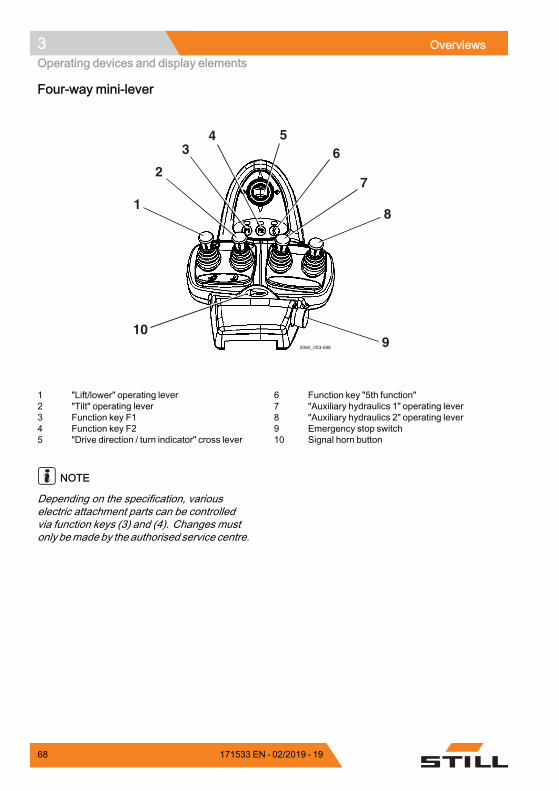
3 OverviewsOperating devices and display elements
Four-way mini-lever
5060_003-088
1
2
34 5
6
7
8
910
1 "Lift/lower" operating lever2 "Tilt" operating lever3 Function key F14 Function key F25 "Drive direction / turn indicator" cross lever
6 Function key "5th function"7 "Auxiliary hydraulics 1" operating lever8 "Auxiliary hydraulics 2" operating lever9 Emergency stop switch10 Signal horn button
NOTE
Depending on the specification, variouselectric attachment parts can be controlledvia function keys (3) and (4). Changes mustonly bemade by the authorised service centre.
68 171533 EN - 02/2019 - 19
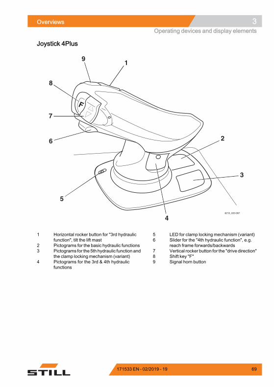
Overviews 3Operating devices and display elements
Joystick 4Plus
1
2
3
4
5
9
8
7
6
6210_003-087
1 Horizontal rocker button for "3rd hydraulicfunction", tilt the lift mast
2 Pictograms for the basic hydraulic functions3 Pictograms for the 5th hydraulic function and
the clamp locking mechanism (variant)4 Pictograms for the 3rd & 4th hydraulic
functions
5 LED for clamp locking mechanism (variant)6 Slider for the "4th hydraulic function", e.g.
reach frame forwards/backwards7 Vertical rocker button for the "drive direction"8 Shift key "F"9 Signal horn button
171533 EN - 02/2019 - 19 69
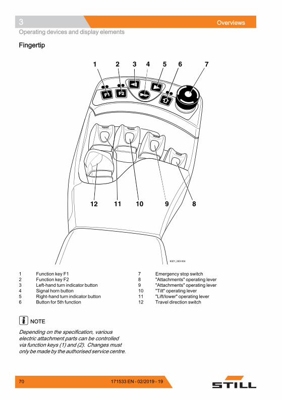
3 OverviewsOperating devices and display elements
Fingertip
F1F1 F2F2
6321_003-004
1 2 3 4 5 6 7
89101112
1 Function key F12 Function key F23 Left-hand turn indicator button4 Signal horn button5 Right-hand turn indicator button6 Button for 5th function
7 Emergency stop switch8 "Attachments" operating lever9 "Attachments" operating lever10 "Tilt" operating lever11 "Lift/lower" operating lever12 Travel direction switch
NOTE
Depending on the specification, variouselectric attachment parts can be controlledvia function keys (1) and (2). Changes mustonly bemade by the authorised service centre.
70 171533 EN - 02/2019 - 19
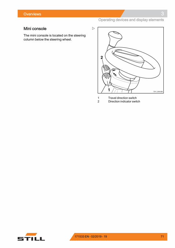
Overviews 3Operating devices and display elements
7311_003-0561
2
1 Travel direction switch2 Direction indicator switch
Mini consoleThe mini console is located on the steeringcolumn below the steering wheel.
171533 EN - 02/2019 - 19 71

3 OverviewsOperating devices and display elements
72 171533 EN - 02/2019 - 19

4
Operation
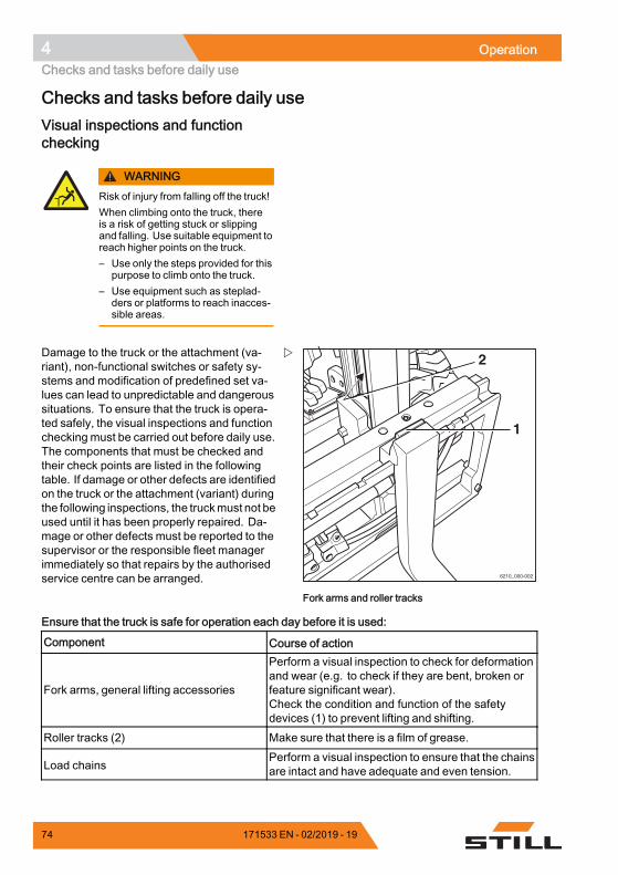
4 OperationChecks and tasks before daily use
Checks and tasks before daily useVisual inspections and functionchecking
WARNINGRisk of injury from falling off the truck!When climbing onto the truck, thereis a risk of getting stuck or slippingand falling. Use suitable equipment toreach higher points on the truck.– Use only the steps provided for this
purpose to climb onto the truck.– Use equipment such as steplad-
ders or platforms to reach inacces-sible areas.
1
2
6210_000-002
Fork arms and roller tracks
Damage to the truck or the attachment (va-riant), non-functional switches or safety sy-stems and modification of predefined set va-lues can lead to unpredictable and dangeroussituations. To ensure that the truck is opera-ted safely, the visual inspections and functionchecking must be carried out before daily use.The components that must be checked andtheir check points are listed in the followingtable. If damage or other defects are identifiedon the truck or the attachment (variant) duringthe following inspections, the truckmust not beused until it has been properly repaired. Da-mage or other defects must be reported to thesupervisor or the responsible fleet managerimmediately so that repairs by the authorisedservice centre can be arranged.
Ensure that the truck is safe for operation each day before it is used:
Component Course of action
Fork arms, general lifting accessories
Perform a visual inspection to check for deformationand wear (e.g. to check if they are bent, broken orfeature significant wear).Check the condition and function of the safetydevices (1) to prevent lifting and shifting.
Roller tracks (2) Make sure that there is a film of grease.
Load chainsPerform a visual inspection to ensure that the chainsare intact and have adequate and even tension.
74 171533 EN - 02/2019 - 19
Operation 4Checks and tasks before daily use
Component Course of action
Attachments (variant)
Ensure that the attachments are mounted correctlyin accordance with the operating instructions fromthe manufacturer.Perform a visual inspection to ensure that the attach-ments are intact and are leak-tight.Perform checks to ensure the attachments areworking correctly.
Lift cylinders, tilt cylinders, tank, valveblock, hoses, pipes, connections
Perform a visual inspection for damage and leak-ages.Have damaged components replaced by the autho-rised service centre.
Underside Check the area under the truck for leaking consum-ables.
Wheels, tyres
Perform a visual inspection for wear and damage.Make sure that only rims of the same type from thesame manufacturer are fitted.In the event of uneven tyre wear, replace both tyres.Observe the safety regulations in the section entitled"Tyres".
Axle Make sure that no consumables are escaping fromthe axle.
Overhead guard, guard grille (variant) Perform a visual inspection for integrity.Check for secure mounting.
Steps Make sure they are clean (free of ice, not slippery).
Panes of glass (variant) Perform a visual inspection for integrity.Make sure they are clean (also free of ice).
Handholds Check for secure mounting.
Maintenance lids Check the close function and close.
Battery hood Make sure that there are no unused bores in thebattery hood.
Battery cover
Perform a visual inspection for integrity and defor-mation.Check that the interlock is in good condition and isworking correctly.Check the close function.Close.
BatteryCheck that the interlock is in good condition and isworking correctly.Lock the battery.
171533 EN - 02/2019 - 19 75
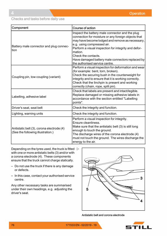
4 OperationChecks and tasks before daily use
Component Course of action
Battery male connector and plug connec-tion
Inspect the battery male connector and the plugconnection for moisture or any foreign objects thatmay havebecome lodged and remove asnecessary,e.g. using compressed air.Perform a visual inspection for integrity and defor-mation.Check the contacts.Have damaged batterymale connectors replaced bythe authorised service centre.
Coupling pin, tow coupling (variant)
Performa visual inspection for deformation andwear(for example: bent, torn, broken).Check the securing bush in the counterweight forintegrity and to ensure that it is working correctly.Check that the linchpin is present and workingcorrectly (chain, rope, split pin).
Labelling, adhesive label
Check that labels are present and intact/legible.Replace damaged or missing adhesive labels inaccordance with the section entitled "Labellingpoints".
Driver's seat, seat belt Check the integrity and function.
Lighting, warning units Check the integrity and function.
Antistatic belt (3), corona electrode (4)(See the following illustration.)
Perform a visual inspection for integrity.Ensure cleanliness.Make sure that the antistatic belt (3) is still longenough to touch the ground.The discharge wires of the corona electrode (4)must not touch the ground. The wires discharge theenergy to the air.
5
Antistatic belt and corona electrode
Depending on the tyres used, the truck is fittedwith one ormore antistatic belts (3) and/or witha corona electrode (4). These componentsensure that the truck cannot charge statically.
– Do not use the truck if there is any damageor defects.
– In this case, contact your authorised servicecentre.
Any other necessary tasks are summarisedunder their own headings, e.g. adjusting thedriver's seat.
76 171533 EN - 02/2019 - 19
Operation 4Checks and tasks before daily use
Climbing into and out of the truck
WARNINGRisk of injury when climbing into and out of thetruck due to slipping, striking parts of the truck orbecoming stuck!If the footwell cover is very dirty or smeared with oil,there is a risk of slipping. There is a risk of hittingyour head on the post of the overhead guard or ofyour clothes becoming stuck when climbing out ofthe truck.– Ensure that the footwell cover is non-slip.– Do not jump into or out of the truck.– Ensure that you have a secure grip on the truck.
WARNINGRisk of injury when jumping out of the truck!If your clothing or jewellery (e.g. watch, ring etc.)becomes stuck on a component while you arejumping out of the truck, this can lead to seriousinjuries (e.g. from falling, loss of fingers etc.). It isforbidden to jump out of the truck.– Do not jump out of the truck.– Do not wear jewellery at work.– Do not wear loose-fitting workwear.
CAUTIONComponents may become damaged throughincorrect use!Truck components, such as the driver's seat,steering wheel, parking brake lever etc., are notdesigned to be used for climbing in and out of thetruck and can be damaged due to misuse.– Only use the fittings specifically designed for the
purpose of climbing into and out of the truck.
171533 EN - 02/2019 - 19 77
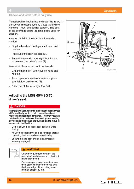
4 OperationChecks and tasks before daily use
6327_003-047_V23
4
5
1
2
Toassistwith climbing into andout of the truck,the footwell must be used as a step (4) and thehandle (1) must be used for support. The postof the overhead guard (5) can also be used forsupport.
Always climb into the truck in a forwardsmotion:
– Grip the handle (1) with your left hand andhold on.
– Put your left foot on the step (3).
– Enter the truck with your right foot first andsit down on the driver's seat (2).
Always climb out of the truck backwards:
– Grip the handle (1) with your left hand andhold on.
– Stand up from the driver's seat and placeyour left foot on the step (3).
– Climb out of the truck right foot first.
Adjusting the MSG 65/MSG 75driver's seat
DANGERThere is a risk of accident if the seat or seat backrestshifts suddenly, which could cause the driver tomove in an uncontrolled manner. This may result inunintentional actuation of the steering or operatingdevices and thus cause the truck or load to move inan uncontrolled fashion.– Do not adjust the seat or seat backrest while
driving– Adjust the seat and the seat backrest so that all
operating devices can be actuated safely– Ensure that the seat and seat backrest are
securely engaged
WARNINGOn some equipment variants, theamount of head clearance on the truckmay be restricted.On these specific equipment variants,the distance between the head andthe lower edge of the roofing sheetmust be at least 40 mm.
78 171533 EN - 02/2019 - 19
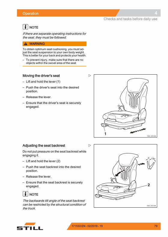
Operation 4Checks and tasks before daily use
NOTE
If there are separate operating instructions forthe seat, they must be followed.
WARNINGTo obtain optimum seat cushioning, you must ad-just the seat suspension to your own body weight.This is better for your back and protects your health.– To prevent injury, make sure that there are no
objects within the swivel area of the seat
7094_003-0061
Moving the driver's seat– Lift and hold the lever (1)
– Push the driver's seat into the desiredposition.
– Release the lever.
– Ensure that the driver's seat is securelyengaged.
7094_003-008
2
Adjusting the seat backrestDo not put pressure on the seat backrest whileengaging it.
– Lift and hold the lever (2)
– Push the seat backrest into the desiredposition.
– Release the lever.
– Ensure that the seat backrest is securelyengaged.
NOTE
The backwards tilt angle of the seat backrestcan be restricted by the structural condition ofthe truck.
171533 EN - 02/2019 - 19 79
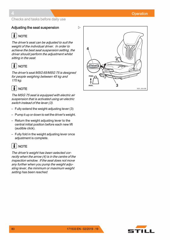
4 OperationChecks and tasks before daily use
6321_003-038
3
4
Adjusting the seat suspension
NOTE
The driver's seat can be adjusted to suit theweight of the individual driver. In order toachieve the best seat suspension setting, thedriver should perform the adjustment whilstsitting in the seat.
NOTE
The driver's seat MSG 65/MSG 75 is designedfor people weighing between 45 kg and170 kg.
NOTE
The MSG 75 seat is equipped with electric airsuspension that is activated using an electricswitch instead of the lever (3).
– Fully extend the weight-adjusting lever (3)
– Pump it up or down to set the driver'sweight.
– Return the weight adjusting lever to thecentral initial position before each new lift(audible click).
– Fully fold in the weight adjusting lever onceadjustment is complete.
NOTE
The driver's weight has been selected cor-rectly when the arrow (4) is in the centre of theinspection window. If the seat does not moveany further when you pump the weight adju-sting lever, the minimum or maximum weightsetting has been reached.
80 171533 EN - 02/2019 - 19
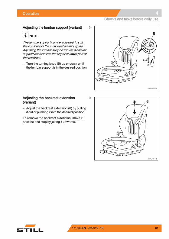
Operation 4Checks and tasks before daily use
6321_003-039
5
Adjusting the lumbar support (variant)
NOTE
The lumbar support can be adjusted to suitthe contours of the individual driver's spine.Adjusting the lumbar support moves a convexsupport cushion into the upper or lower part ofthe backrest.
– Turn the turning knob (5) up or down untilthe lumbar support is in the desired position
6321_003-040
6Adjusting the backrest extension(variant)– Adjust the backrest extension (6) by pullingit out or pushing it into the desired position.
To remove the backrest extension, move itpast the end stop by jolting it upwards.
171533 EN - 02/2019 - 19 81
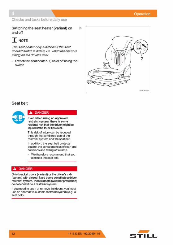
4 OperationChecks and tasks before daily use
6321_003-041
7
Switching the seat heater (variant) onand off
NOTE
The seat heater only functions if the seatcontact switch is active, i.e. when the driver issitting on the driver's seat.
– Switch the seat heater (7) on or off using theswitch.
Seat belt
DANGEREven when using an approvedrestraint system, there is someresidual risk that the driver might beinjured if the truck tips over.This risk of injury can be reducedthrough the combined use of therestraint system and the seat belt.In addition, the seat belt protectsagainst the consequences of rear-endcollisions and falling off a ramp.– We therefore recommend that you
also use the seat belt.
DANGEROnly bracket doors (variant) or the driver's cab(variant) with closed, fixed doors constitute a driverrestraint system. Plastic doors (weather protection)do not constitute a restraint system!If you need to open or remove the doors, you mustuse an alternative suitable restraint system (e.g. aseat belt).
82 171533 EN - 02/2019 - 19
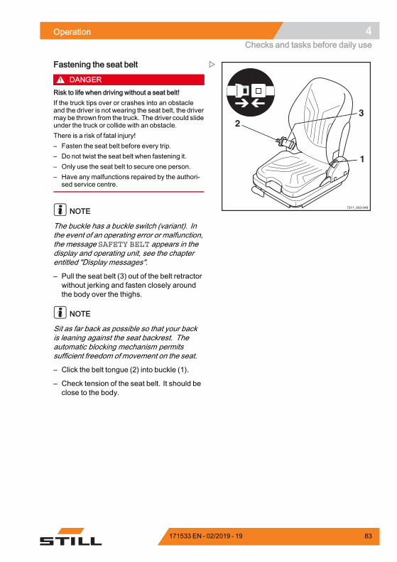
Operation 4Checks and tasks before daily use
7311_003-048
1
23
Fastening the seat belt
DANGERRisk to life when driving without a seat belt!If the truck tips over or crashes into an obstacleand the driver is not wearing the seat belt, the drivermay be thrown from the truck. The driver could slideunder the truck or collide with an obstacle.There is a risk of fatal injury!– Fasten the seat belt before every trip.– Do not twist the seat belt when fastening it.– Only use the seat belt to secure one person.– Have any malfunctions repaired by the authori-
sed service centre.
NOTE
The buckle has a buckle switch (variant). Inthe event of an operating error or malfunction,the message SAFETY BELT appears in thedisplay and operating unit, see the chapterentitled "Display messages".
– Pull the seat belt (3) out of the belt retractorwithout jerking and fasten closely aroundthe body over the thighs.
NOTE
Sit as far back as possible so that your backis leaning against the seat backrest. Theautomatic blocking mechanism permitssufficient freedom of movement on the seat.
– Click the belt tongue (2) into buckle (1).
– Check tension of the seat belt. It should beclose to the body.
171533 EN - 02/2019 - 19 83
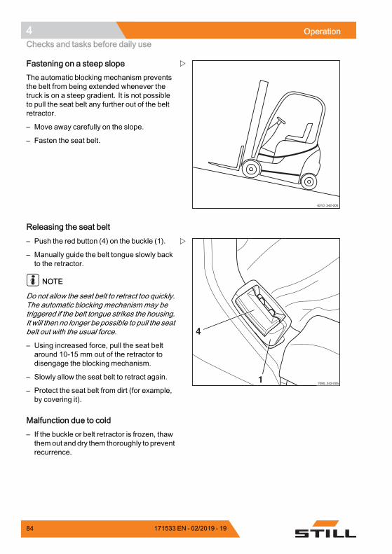
4 OperationChecks and tasks before daily use
6210_342-005
Fastening on a steep slopeThe automatic blocking mechanism preventsthe belt from being extended whenever thetruck is on a steep gradient. It is not possibleto pull the seat belt any further out of the beltretractor.
– Move away carefully on the slope.
– Fasten the seat belt.
Releasing the seat belt
7090_342-0051
4
– Push the red button (4) on the buckle (1).
– Manually guide the belt tongue slowly backto the retractor.
NOTE
Do not allow the seat belt to retract too quickly.The automatic blocking mechanism may betriggered if the belt tongue strikes the housing.It will then no longer be possible to pull the seatbelt out with the usual force.
– Using increased force, pull the seat beltaround 10-15 mm out of the retractor todisengage the blocking mechanism.
– Slowly allow the seat belt to retract again.
– Protect the seat belt from dirt (for example,by covering it).
Malfunction due to cold– If the buckle or belt retractor is frozen, thawthemout anddry them thoroughly to preventrecurrence.
84 171533 EN - 02/2019 - 19
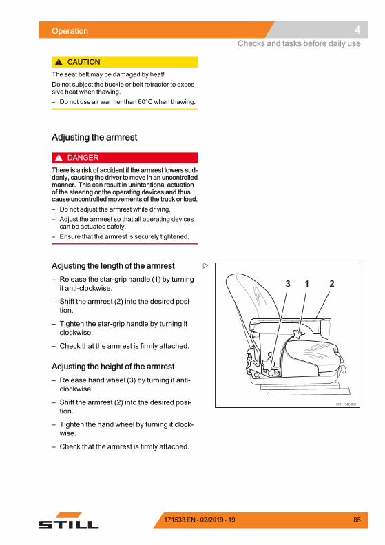
Operation 4Checks and tasks before daily use
CAUTIONThe seat belt may be damaged by heat!Do not subject the buckle or belt retractor to exces-sive heat when thawing.– Do not use air warmer than 60°C when thawing.
Adjusting the armrest
DANGERThere is a risk of accident if the armrest lowers sud-denly, causing the driver tomove in an uncontrolledmanner. This can result in unintentional actuationof the steering or the operating devices and thuscause uncontrolled movements of the truck or load.– Do not adjust the armrest while driving.– Adjust the armrest so that all operating devices
can be actuated safely.– Ensure that the armrest is securely tightened.
7331_342-001
3 1 2
Adjusting the length of the armrest– Release the star-grip handle (1) by turningit anti-clockwise.
– Shift the armrest (2) into the desired posi-tion.
– Tighten the star-grip handle by turning itclockwise.
– Check that the armrest is firmly attached.
Adjusting the height of the armrest– Release hand wheel (3) by turning it anti-clockwise.
– Shift the armrest (2) into the desired posi-tion.
– Tighten the hand wheel by turning it clock-wise.
– Check that the armrest is firmly attached.
171533 EN - 02/2019 - 19 85
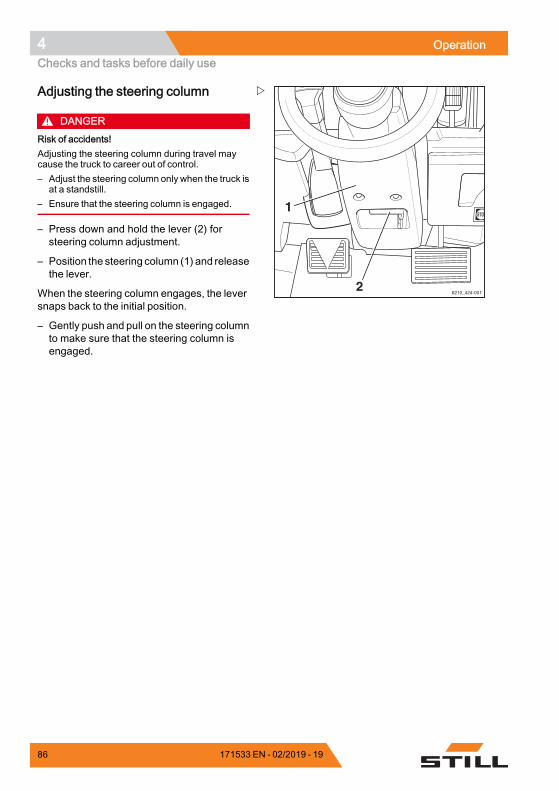
4 OperationChecks and tasks before daily use
6210_424-001
1
2
Adjusting the steering column
DANGERRisk of accidents!Adjusting the steering column during travel maycause the truck to career out of control.– Adjust the steering column only when the truck is
at a standstill.– Ensure that the steering column is engaged.
– Press down and hold the lever (2) forsteering column adjustment.
– Position the steering column (1) and releasethe lever.
When the steering column engages, the leversnaps back to the initial position.
– Gently push and pull on the steering columnto make sure that the steering column isengaged.
86 171533 EN - 02/2019 - 19
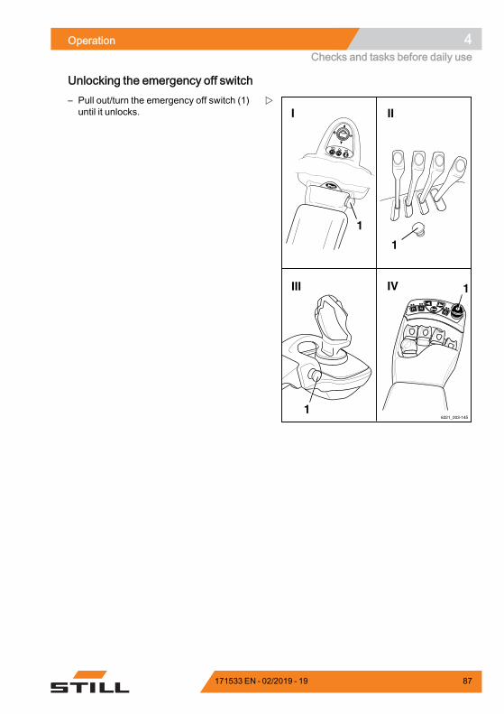
Operation 4Checks and tasks before daily use
Unlocking the emergency off switch
6321_003-145
F1F1 F2F2
1
IV
I
III
II
F1 F2
1
1
1
– Pull out/turn the emergency off switch (1)until it unlocks.
171533 EN - 02/2019 - 19 87
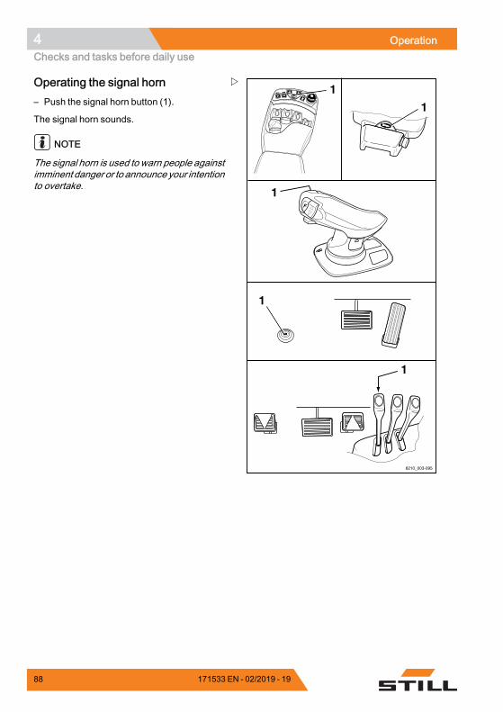
4 OperationChecks and tasks before daily use
F1F1 F2F2
6210_003-095
1
1
1
1
1
Operating the signal horn– Push the signal horn button (1).
The signal horn sounds.
NOTE
The signal horn is used to warn people againstimminent danger or to announce your intentionto overtake.
88 171533 EN - 02/2019 - 19
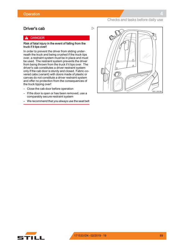
Operation 4Checks and tasks before daily use
6321_003-094
Driver's cab
DANGERRisk of fatal injury in the event of falling from thetruck if it tips over!In order to prevent the driver from sliding under-neath the truck and being crushed if the truck tipsover, a restraint systemmust be in place and mustbe used. The restraint system prevents the driverfrom being thrown from the truck if it tips over. Thedriver's cab constitutes a driver restraint systemonly if the cab door is sturdy and closed. Fabric-co-vered cabs (variant) with doors made of plastic orcanvas do not constitute a driver restraint systemand offer no protection from the consequences ofthe truck tipping over!– Close the cab door before operation– If the door is open or has been removed, use a
comparably secure restraint system– We recommend that you always use the seat belt
171533 EN - 02/2019 - 19 89
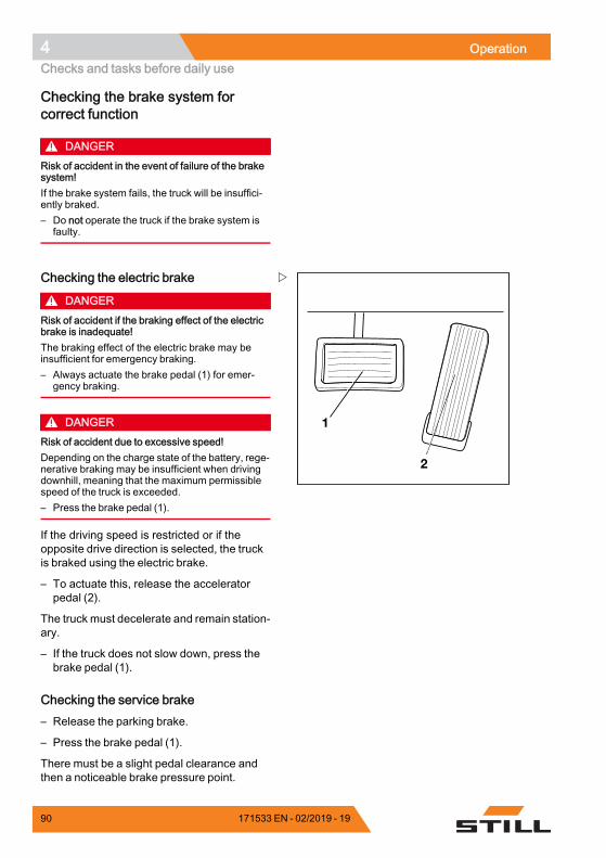
4 OperationChecks and tasks before daily use
Checking the brake system forcorrect function
DANGERRisk of accident in the event of failure of the brakesystem!If the brake system fails, the truck will be insuffici-ently braked.– Do not operate the truck if the brake system is
faulty.
1
2
Checking the electric brake
DANGERRisk of accident if the braking effect of the electricbrake is inadequate!The braking effect of the electric brake may beinsufficient for emergency braking.– Always actuate the brake pedal (1) for emer-
gency braking.
DANGERRisk of accident due to excessive speed!Depending on the charge state of the battery, rege-nerative braking may be insufficient when drivingdownhill, meaning that the maximum permissiblespeed of the truck is exceeded.– Press the brake pedal (1).
If the driving speed is restricted or if theopposite drive direction is selected, the truckis braked using the electric brake.
– To actuate this, release the acceleratorpedal (2).
The truck must decelerate and remain station-ary.
– If the truck does not slow down, press thebrake pedal (1).
Checking the service brake– Release the parking brake.
– Press the brake pedal (1).
There must be a slight pedal clearance andthen a noticeable brake pressure point.
90 171533 EN - 02/2019 - 19
Operation 4Checks and tasks before daily use
– Accelerate the unladen truck in a clear area.
– Press the brake pedal (1) firmly.
The truck must decelerate noticeably.
Checking the parking brake on a gradientor a ramp
DANGERRisk to life if the truck rolls away!If the parking brake is not applied, thetruck could run people over.– Do not leave the truck until the
parking brake has been applied.
– Stop the truck on a steep gradient (e.g. aramp) and actuate the parking brake.
The parking brake must hold the truck on theincline.
– If the truck rolls away despite the parkingbrake being applied, stop the truck usingthe service brake.
– In an emergency, secure the truck withwedges on the downhill-facing side toprevent it from rolling away.
– Have the parking brake checked andrepaired by the authorised service centre.
Checking the parking brake on a levelsurface
WARNINGRisk of accident from abrupt deceleration!The truck will decelerate abruptly if the parkingbrake is applied.– Fasten the seat belt.– Use the available restraint systems.
– Find a sufficiently large and open areain which nobody will be endangered orobstructed.
– Accelerate the truck to walking speed.
– Press the emergency off switch.
171533 EN - 02/2019 - 19 91
4 OperationChecks and tasks before daily use
NOTE
When the emergency off switch is actuated,note the following:• The electric brake is disabled. The truck nolonger responds to the command issued bythe accelerator pedal.
• The power steering is no longer available.Steering forces are increased due to theremaining emergency steering function.
– Release the accelerator pedal.
– Apply the parking brake.
The truck must decelerate and remain station-ary.
– If the truck only coasts and does not decel-erate or decelerates only slightly, stop thetruck using the service brake.
– Secure the truck with chocks so that thetruck does not roll away.
– Have the parking brake checked andrepaired by the authorised service centre.
NOTE
Special features of the electrical parkingbrake:• The deceleration cannot be influenced.• The electrical parking brake is appliedmoderately until the truck comes to a stop.
• The emergency off switchmust be unlockedto release the electrical parking brake.
92 171533 EN - 02/2019 - 19
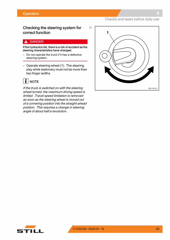
Operation 4Checks and tasks before daily use
5060_003-031
1Checking the steering system forcorrect function
DANGERIf the hydraulics fail, there is a risk of accident as thesteering characteristics have changed.– Do not operate the truck if it has a defective
steering system.
– Operate steering wheel (1). The steeringplay while stationary must not be more thantwo finger widths.
NOTE
If the truck is switched on with the steeringwheel turned, the maximum driving speed islimited. Travel speed limitation is removedas soon as the steering wheel is moved outof a cornering position into the straight-aheadposition. This requires a change in steeringangle of about half a revolution.
171533 EN - 02/2019 - 19 93
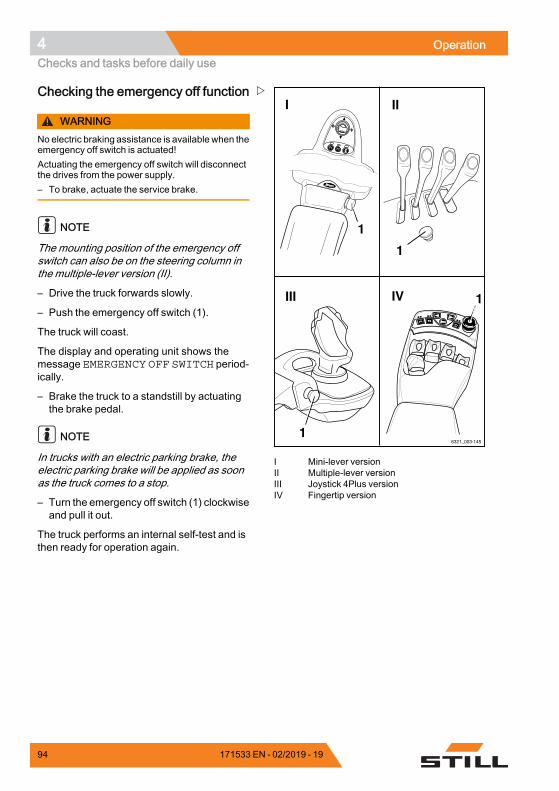
4 OperationChecks and tasks before daily use
6321_003-145
F1F1 F2F2
1
IV
I
III
II
F1 F2
1
1
1
I Mini-lever versionII Multiple-lever versionIII Joystick 4Plus versionIV Fingertip version
Checking the emergency off function
WARNINGNo electric braking assistance is available when theemergency off switch is actuated!Actuating the emergency off switch will disconnectthe drives from the power supply.– To brake, actuate the service brake.
NOTE
The mounting position of the emergency offswitch can also be on the steering column inthe multiple-lever version (II).
– Drive the truck forwards slowly.
– Push the emergency off switch (1).
The truck will coast.
The display and operating unit shows themessage EMERGENCY OFF SWITCH period-ically.
– Brake the truck to a standstill by actuatingthe brake pedal.
NOTE
In trucks with an electric parking brake, theelectric parking brake will be applied as soonas the truck comes to a stop.
– Turn the emergency off switch (1) clockwiseand pull it out.
The truck performs an internal self-test and isthen ready for operation again.
94 171533 EN - 02/2019 - 19
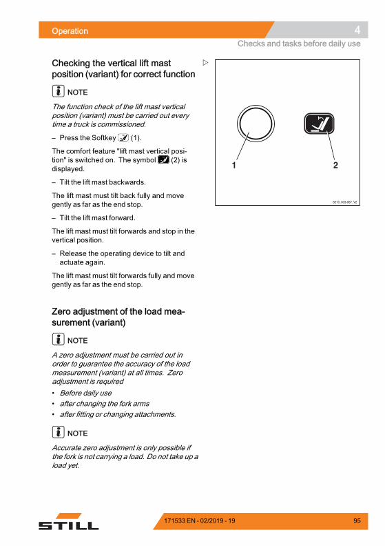
Operation 4Checks and tasks before daily use
6210_003-067_V2
21
Checking the vertical lift mastposition (variant) for correct function
NOTE
The function check of the lift mast verticalposition (variant) must be carried out everytime a truck is commissioned.
– Press the Softkey (1).
The comfort feature "lift mast vertical posi-tion" is switched on. The symbol (2) isdisplayed.
– Tilt the lift mast backwards.
The lift mast must tilt back fully and movegently as far as the end stop.
– Tilt the lift mast forward.
The lift mast must tilt forwards and stop in thevertical position.
– Release the operating device to tilt andactuate again.
The lift mast must tilt forwards fully and movegently as far as the end stop.
Zero adjustment of the load mea-surement (variant)
NOTE
A zero adjustment must be carried out inorder to guarantee the accuracy of the loadmeasurement (variant) at all times. Zeroadjustment is required• Before daily use• after changing the fork arms• after fitting or changing attachments.
NOTE
Accurate zero adjustment is only possible ifthe fork is not carrying a load. Do not take up aload yet.
171533 EN - 02/2019 - 19 95
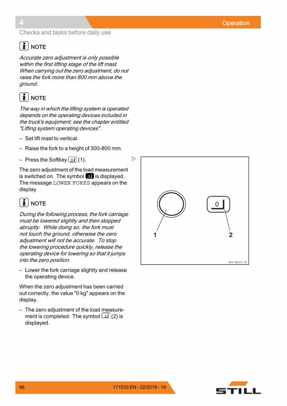
4 OperationChecks and tasks before daily use
NOTE
Accurate zero adjustment is only possiblewithin the first lifting stage of the lift mast.When carrying out the zero adjustment, do notraise the fork more than 800 mm above theground.
NOTE
The way in which the lifting system is operateddepends on the operating devices included inthe truck's equipment; see the chapter entitled"Lifting system operating devices".
– Set lift mast to vertical.
– Raise the fork to a height of 300-800 mm.
6210_003-071_V2
21
– Press the Softkey (1).
The zero adjustment of the loadmeasurementis switched on. The symbol is displayed.The message LOWER FORKS appears on thedisplay.
NOTE
During the following process, the fork carriagemust be lowered slightly and then stoppedabruptly. While doing so, the fork mustnot touch the ground, otherwise the zeroadjustment will not be accurate. To stopthe lowering procedure quickly, release theoperating device for lowering so that it jumpsinto the zero position.
– Lower the fork carriage slightly and releasethe operating device.
When the zero adjustment has been carriedout correctly, the value "0 kg" appears on thedisplay.
– The zero adjustment of the load measure-ment is completed. The symbol (2) isdisplayed.
96 171533 EN - 02/2019 - 19
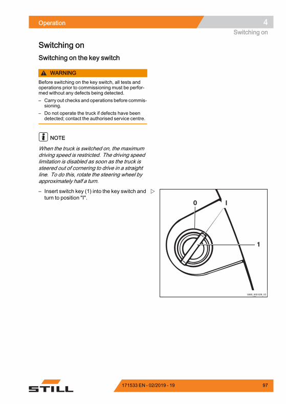
Operation 4Switching on
Switching onSwitching on the key switch
WARNINGBefore switching on the key switch, all tests andoperations prior to commissioning must be perfor-med without any defects being detected.– Carry out checks and operations before commis-
sioning.– Do not operate the truck if defects have been
detected; contact the authorised service centre.
NOTE
When the truck is switched on, the maximumdriving speed is restricted. The driving speedlimitation is disabled as soon as the truck issteered out of cornering to drive in a straightline. To do this, rotate the steering wheel byapproximately half a turn.
I
1
0
5060_003-029_V2
– Insert switch key (1) into the key switch andturn to position "I".
171533 EN - 02/2019 - 19 97
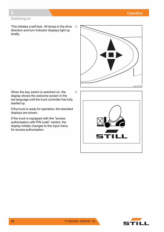
4 OperationSwitching on
7312_003-085
This initiates a self-test. All lamps in the drivedirection and turn indicator displays light upbriefly.
When the key switch is switched on, thedisplay shows the welcome screen in theset language until the truck controller has fullystarted up.
If the truck is ready for operation, the standarddisplays are shown.
If the truck is equipped with the "accessauthorisation with PIN code" variant, thedisplay initially changes to the input menufor access authorisation.
98 171533 EN - 02/2019 - 19
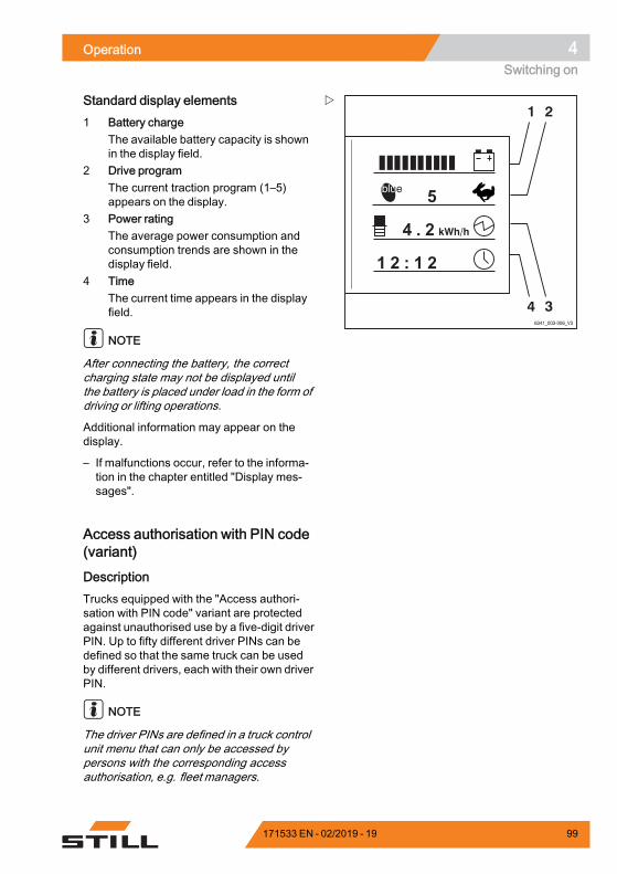
Operation 4Switching on
1 2
346341_003-006_V3
Standard display elements1 Battery charge
The available battery capacity is shownin the display field.
2 Drive programThe current traction program (1–5)appears on the display.
3 Power ratingThe average power consumption andconsumption trends are shown in thedisplay field.
4 TimeThe current time appears in the displayfield.
NOTE
After connecting the battery, the correctcharging state may not be displayed untilthe battery is placed under load in the form ofdriving or lifting operations.
Additional information may appear on thedisplay.
– If malfunctions occur, refer to the informa-tion in the chapter entitled "Display mes-sages".
Access authorisation with PIN code(variant)
DescriptionTrucks equipped with the "Access authori-sation with PIN code" variant are protectedagainst unauthorised use by a five-digit driverPIN. Up to fifty different driver PINs can bedefined so that the same truck can be usedby different drivers, each with their own driverPIN.
NOTE
The driver PINs are defined in a truck controlunit menu that can only be accessed bypersons with the corresponding accessauthorisation, e.g. fleet managers.
171533 EN - 02/2019 - 19 99
4 OperationSwitching on
Once the key switch has been switched on,the input menu for the driver PIN appearson the display and operating unit screen. Allof the truck's functions (driving, hydraulics,additional electrical installations and thedisplay and operating unit displays) areblocked. The function of the hazard warningsystem (variant) is guaranteed. Enter the five-digit driver PIN (possible entries from 00000 to99999) to enable the blocked functions. Oncethe correct driver PIN has been entered, thestandard displays are shown. All of the truckfunctions are available.
The access authorisation can be configuredin such a way that the driver PIN has to bere-entered each time the driver steps off thetruck, in order for the truck to be operatedagain.
– Contact the authorised service centre onthis matter.
The first driver PIN is preset to "11111" at thefactory. All others are preset to "0xFFF" buthave no function as the highest valid driverPIN is "99999". Persons with the appropriateaccessauthorisation, e.g. fleetmanagers, canchange the driver PINs in the correspondingmenu.
NOTE
When first commissioning the truck, we re-commend you change the access authorisa-tion set at the factory. This is the only way toguarantee that the driver PIN is only known topersons with corresponding access authori-sation.
The driver PINs are stored in the truck controlunit. These are still available if the displayand operating unit has been changed. Theauthorised service centre can use a diagnosticdevice to read out the driver PIN and, ifnecessary, restore the factory default driverPIN.
100 171533 EN - 02/2019 - 19
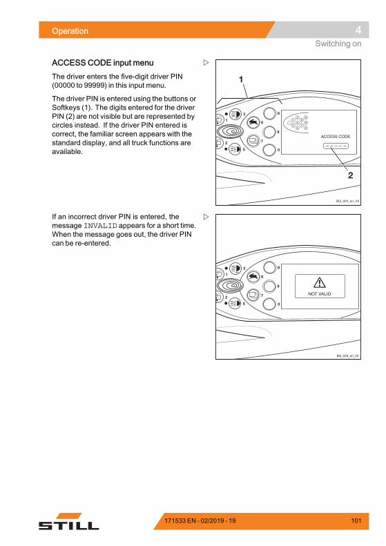
Operation 4Switching on
ACCESS CODE input menuThe driver enters the five-digit driver PIN(00000 to 99999) in this input menu.
The driver PIN is entered using the buttons orSoftkeys (1). The digits entered for the driverPIN (2) are not visible but are represented bycircles instead. If the driver PIN entered iscorrect, the familiar screen appears with thestandard display, and all truck functions areavailable.
8
9
6
7
4
2
0
1
3
5
BQ_023_en_V2
If an incorrect driver PIN is entered, themessage INVALID appears for a short time.When the message goes out, the driver PINcan be re-entered.
171533 EN - 02/2019 - 19 101
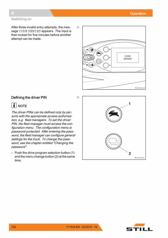
4 OperationSwitching on
8
9
6
7
4
2
0
1
3
5
BQ_024_en_V2
After three invalid entry attempts, the mes-sage CODE DENIED appears. The input isthen locked for five minutes before anotherattempt can be made.
Blue-Q_029_V2
1
2
Defining the driver PIN
NOTE
The driver PINs can be defined only by per-sons with the appropriate access authorisa-tion, e.g. fleet managers. To set the driverPIN, the fleet manager must access the con-figuration menu. The configuration menu ispassword-protected. After entering the pass-word, the fleet manager can configure generalsettings for the truck. To change the pass-word, see the chapter entitled "Changing thepassword".
– Push the drive program selection button (1)and themenu change button (2) at the sametime.
102 171533 EN - 02/2019 - 19
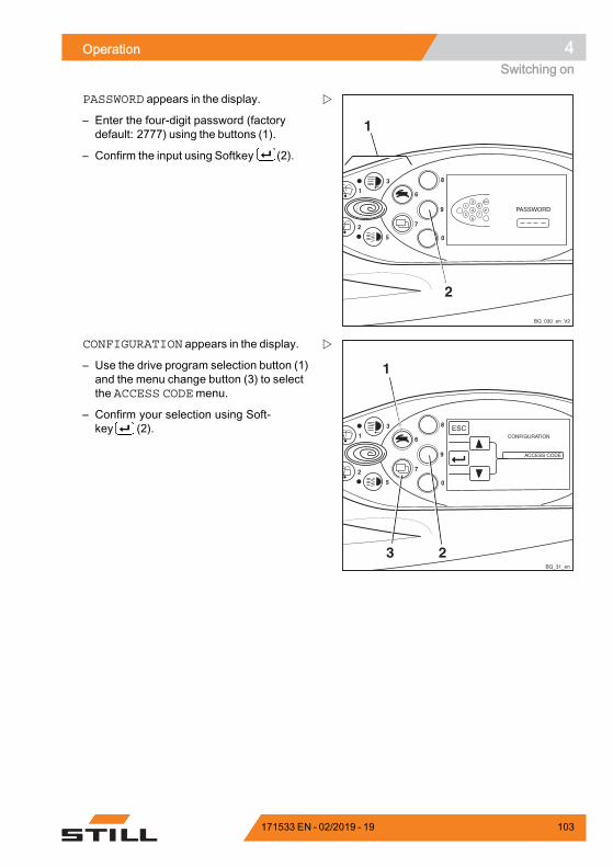
Operation 4Switching on
8
9
6
7
4
2
0
1
3
5
1
2
BQ_030_en_V2
1
2
6
7
3
4
5
ESC
PASSWORD appears in the display.
– Enter the four-digit password (factorydefault: 2777) using the buttons (1).
– Confirm the input using Softkey (2).
8
9
6
7
4
2
0
1
3
5
BQ_31_en
1
3 2
CONFIGURATION appears in the display.
– Use the drive program selection button (1)and the menu change button (3) to selectthe ACCESS CODEmenu.
– Confirm your selection using Soft-key (2).
171533 EN - 02/2019 - 19 103
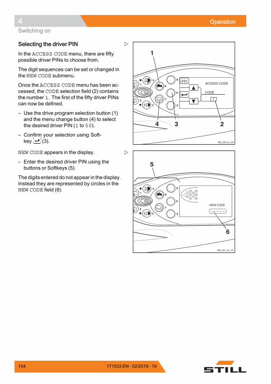
4 OperationSwitching on
8
9
6
7
4
2
0
1
3
5
BQ_025_en_V3
1
34 2
Selecting the driver PINIn the ACCESS CODEmenu, there are fiftypossible driver PINs to choose from.
The digit sequences can be set or changed inthe NEW CODE submenu.
Once the ACCESS CODEmenu has been ac-cessed, the CODE selection field (2) containsthe number 1. The first of the fifty driver PINscan now be defined.
– Use the drive program selection button (1)and the menu change button (4) to selectthe desired driver PIN (1 to 50).
– Confirm your selection using Soft-key (3).
NEW CODE appears in the display.
– Enter the desired driver PIN using thebuttons or Softkeys (5).
The digits entered donot appear in the display.Instead they are represented by circles in theNEW CODE field (6).
104 171533 EN - 02/2019 - 19
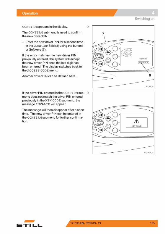
Operation 4Switching on
8
9
6
7
4
2
0
1
3
5
7
8
1
2
6
7
3
4
5
8
9
0
BQ_026_en
CONFIRM appears in the display.
The CONFIRM submenu is used to confirmthe new driver PIN.
– Enter the new driver PIN for a second timein the CONFIRM field (8) using the buttonsor Softkeys (7).
If the entry matches the new driver PINpreviously entered, the system will acceptthe new driver PIN once the last digit hasbeen entered. The display switches back tothe ACCESS CODEmenu.
Another driver PIN can be defined here.
8
9
6
7
4
2
0
1
3
5
BQ_023_en_V2
If the driver PIN entered in the CONFIRM sub-menu does not match the driver PIN enteredpreviously in the NEW CODE submenu, themessage INVALIDwill appear.
The message will then disappear after a shorttime. The new driver PIN can be entered inthe CONFIRM submenu for further confirma-tion.
171533 EN - 02/2019 - 19 105
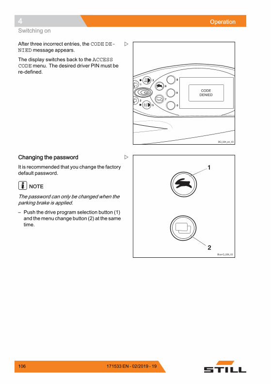
4 OperationSwitching on
8
9
6
7
4
2
0
1
3
5
BQ_024_en_V2
After three incorrect entries, the CODE DE-NIEDmessage appears.
The display switches back to the ACCESSCODEmenu. The desired driver PIN must bere-defined.
Blue-Q_029_V2
1
2
Changing the passwordIt is recommended that you change the factorydefault password.
NOTE
The password can only be changed when theparking brake is applied.
– Push the drive program selection button (1)and themenu change button (2) at the sametime.
106 171533 EN - 02/2019 - 19
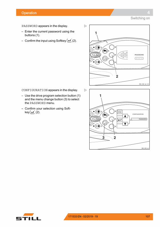
Operation 4Switching on
8
9
6
7
4
2
0
1
3
5
1
2
BQ_030_en_V2
1
2
6
7
3
4
5
ESC
PASSWORD appears in the display.
– Enter the current password using thebuttons (1).
– Confirm the input using Softkey (2).
8
9
6
7
4
2
0
1
3
5
1
23
BQ_032_en
CONFIGURATION appears in the display.
– Use the drive program selection button (1)and the menu change button (3) to selectthe PASSWORDmenu.
– Confirm your selection using Soft-key (2).
171533 EN - 02/2019 - 19 107
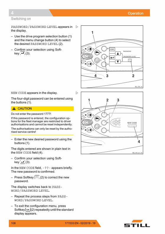
4 OperationSwitching on
8
9
6
7
4
2
0
1
3
5
1
34
BQ_033_en
2
1
PASSWORD/PASSWORD LEVEL appears inthe display.
– Use the drive program selection button (1)and the menu change button (4) to selectthe desired PASSWORD LEVEL (2).
– Confirm your selection using Soft-key (3).
8
9
6
7
4
2
0
1
3
5
1
2
6
7
3
4
5
ESC
BQ_034_en_V2
1 2 3
4
NEW CODE appears in the display.
The four-digit password can be entered usingthe buttons (1).
CAUTIONDo not enter the password 1777!If this password is entered, the configuration op-tions for the fleet manager are restricted to driverauthorisations and cannot be reset independently.The authorisations can only be reset by the autho-rised service centre!
– Enter the new desired password using thebuttons (1).
The digits entered are shown in plain text inthe NEW CODE field (4).
– Confirm your selection using Soft-key (3).
In the NEW CODE field, -??- appears briefly.The new password is confirmed.
– Press Softkey (2) to correct the newpassword.
The display switches back to PASS-WORD/PASSWORD LEVEL.
– Repeat the process steps from PASS-WORD/PASSWORD LEVEL.
– To exit the configuration menu, pressSoftkey (2) repeatedly until the standarddisplay appears.
108 171533 EN - 02/2019 - 19
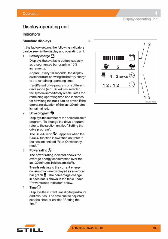
Operation 4Display-operating unit
Display-operating unitIndicators
1 2
346341_003-006_V3
Standard displays
In the factory setting, the following indicatorscan be seen in the display and operating unit:1 Battery charge
Displays the available battery capacityas a segmented bar graph in 10%increments.Approx. every 10 seconds, the displayswitches fromshowing the battery chargeto the remaining operating time.If a different drive program or a differentdrive mode (e.g. Blue-Q) is selected,the system immediately recalculates theremaining operating time and indicatesfor how long the truck can be driven if theoperating situation of the last 30 minutesis maintained.
2 Drive programDisplays the number of the selected driveprogram. To change the drive program,refer to the section entitled "Setting thedrive program".The Blue-Q icon appears when theBlue-Q function is switched on; refer tothe section entitled "Blue-Q efficiencymode".
3 Power ratingThe power rating indicator shows theaverage energy consumption over thelast 30 minutes in kilowatts (kW).Trends relating to the current energyconsumption are displayed as a verticalbar graph . The percentage changein each bar is shown in the table under"Power trends indicator" below.
4 TimeDisplays the current time digitally in hoursand minutes. The time can be adjusted;see the chapter entitled "Setting thetime".
171533 EN - 02/2019 - 19 109
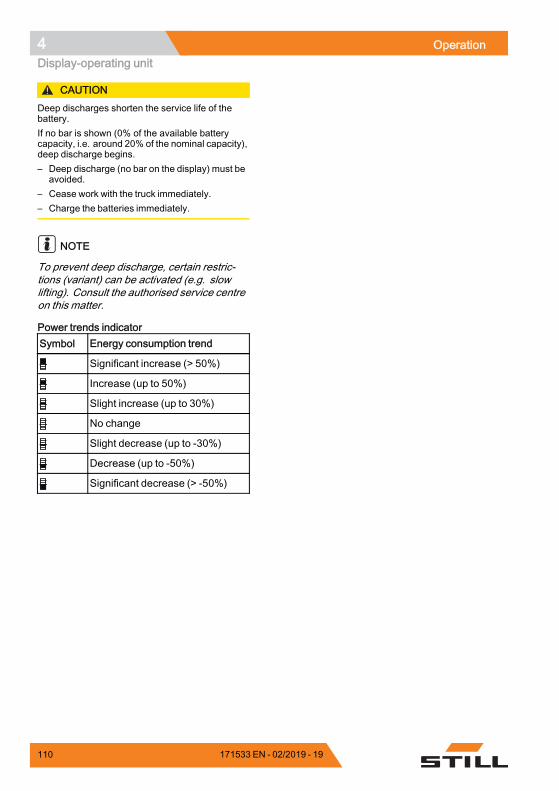
4 OperationDisplay-operating unit
CAUTIONDeep discharges shorten the service life of thebattery.If no bar is shown (0% of the available batterycapacity, i.e. around 20% of the nominal capacity),deep discharge begins.– Deep discharge (no bar on the display) must be
avoided.– Cease work with the truck immediately.– Charge the batteries immediately.
NOTE
To prevent deep discharge, certain restric-tions (variant) can be activated (e.g. slowlifting). Consult the authorised service centreon this matter.
Power trends indicatorSymbol Energy consumption trend
Significant increase (> 50%)
Increase (up to 50%)
Slight increase (up to 30%)
No change
Slight decrease (up to -30%)
Decrease (up to -50%)
Significant decrease (> -50%).
110 171533 EN - 02/2019 - 19
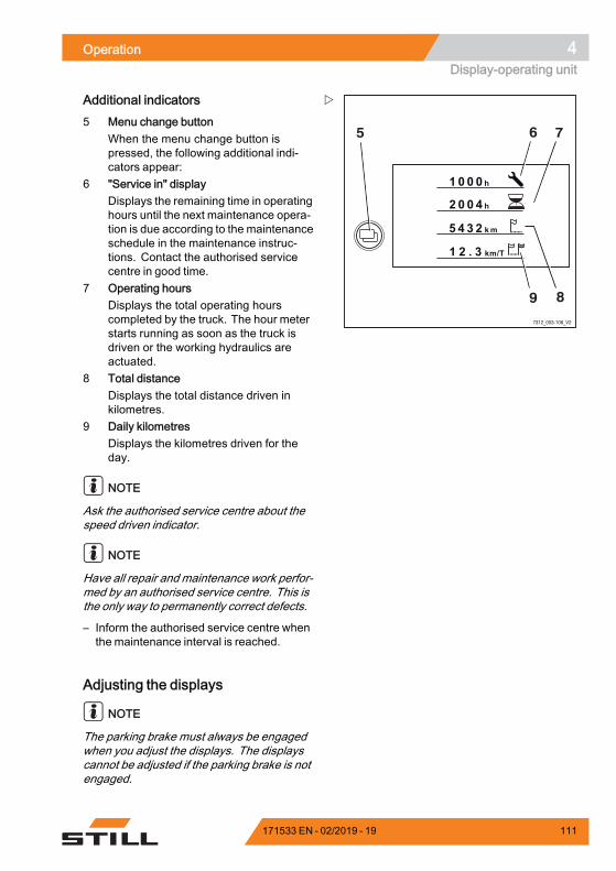
Operation 4Display-operating unit
7312_003-106_V2
6
89
75
Additional indicators5 Menu change button
When the menu change button ispressed, the following additional indi-cators appear:
6 "Service in" displayDisplays the remaining time in operatinghours until the next maintenance opera-tion is due according to the maintenanceschedule in the maintenance instruc-tions. Contact the authorised servicecentre in good time.
7 Operating hoursDisplays the total operating hourscompleted by the truck. The hour meterstarts running as soon as the truck isdriven or the working hydraulics areactuated.
8 Total distanceDisplays the total distance driven inkilometres.
9 Daily kilometresDisplays the kilometres driven for theday.
NOTE
Ask the authorised service centre about thespeed driven indicator.
NOTE
Have all repair and maintenance work perfor-med by an authorised service centre. This isthe only way to permanently correct defects.
– Inform the authorised service centre whenthe maintenance interval is reached.
Adjusting the displays
NOTE
The parking brake must always be engagedwhen you adjust the displays. The displayscannot be adjusted if the parking brake is notengaged.
171533 EN - 02/2019 - 19 111
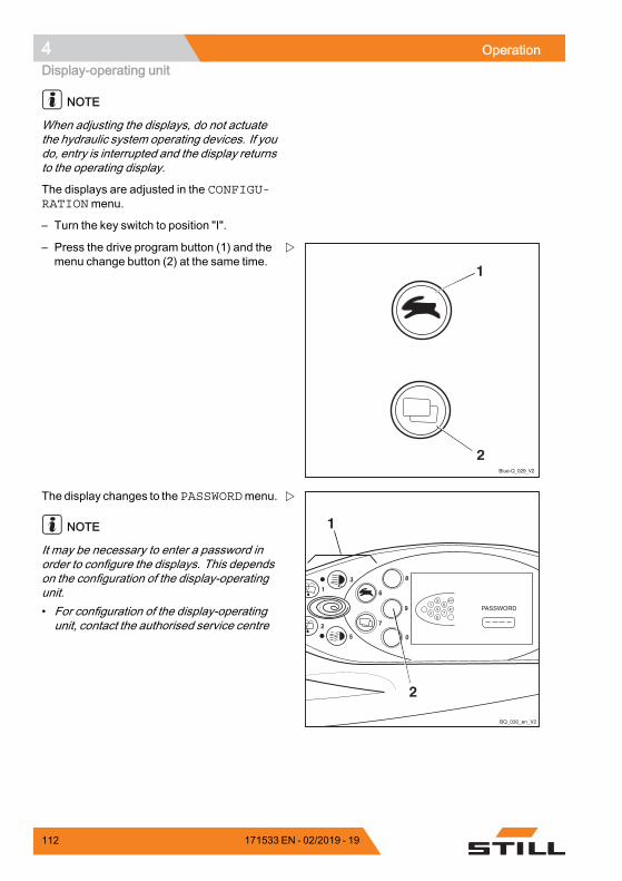
4 OperationDisplay-operating unit
NOTE
When adjusting the displays, do not actuatethe hydraulic system operating devices. If youdo, entry is interrupted and the display returnsto the operating display.
The displays are adjusted in the CONFIGU-RATIONmenu.
– Turn the key switch to position "I".
Blue-Q_029_V2
1
2
– Press the drive program button (1) and themenu change button (2) at the same time.
8
9
6
7
4
2
0
1
3
5
1
2
BQ_030_en_V2
1
2
6
7
3
4
5
ESC
The display changes to thePASSWORDmenu.
NOTE
It may be necessary to enter a password inorder to configure the displays. This dependson the configuration of the display-operatingunit.• For configuration of the display-operatingunit, contact the authorised service centre
112 171533 EN - 02/2019 - 19
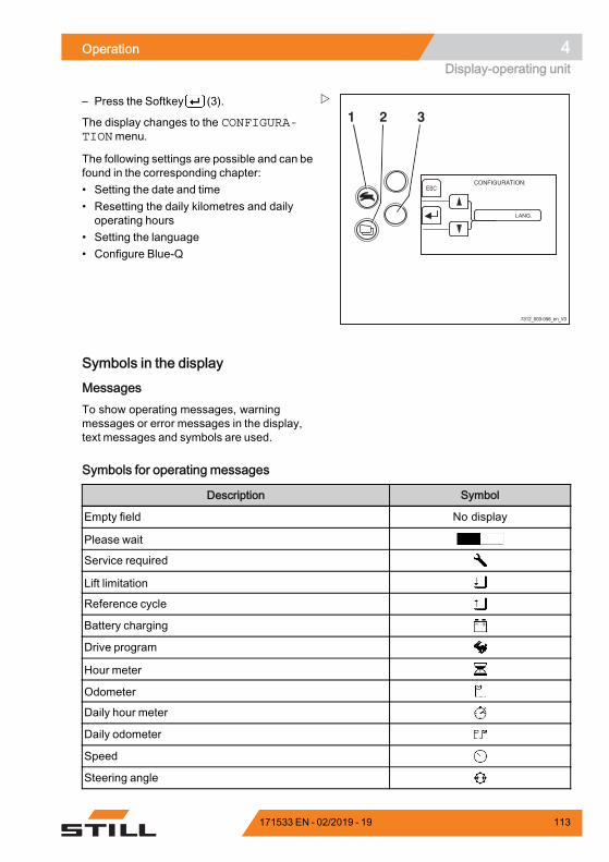
Operation 4Display-operating unit
7312_003-056_en_V3
ESC
1 2 3– Press the Softkey (3).
The display changes to the CONFIGURA-TIONmenu.
The following settings are possible and can befound in the corresponding chapter:• Setting the date and time• Resetting the daily kilometres and dailyoperating hours
• Setting the language• Configure Blue-Q
Symbols in the display
MessagesTo show operating messages, warningmessages or error messages in the display,text messages and symbols are used.
Symbols for operating messages
Description Symbol
Empty field No display
Please wait
Service required
Lift limitation
Reference cycle
Battery charging
Drive program
Hour meter
Odometer
Daily hour meter
Daily odometer
Speed
Steering angle
171533 EN - 02/2019 - 19 113
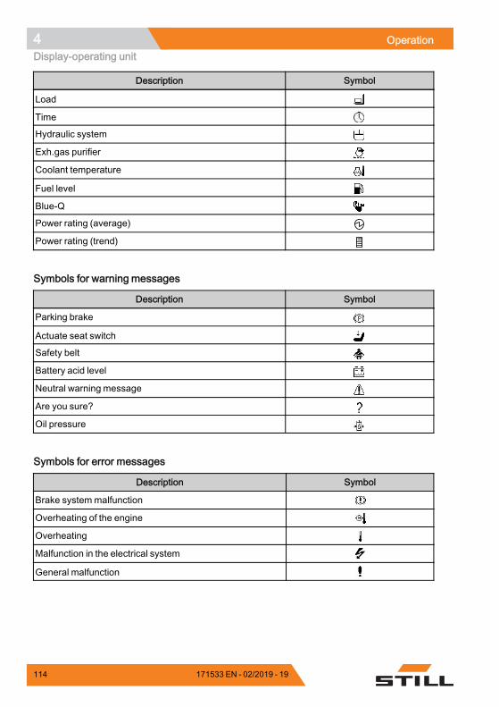
4 OperationDisplay-operating unit
Description Symbol
Load
Time
Hydraulic system
Exh.gas purifier
Coolant temperature
Fuel level
Blue-Q
Power rating (average)
Power rating (trend).
Symbols for warning messages
Description Symbol
Parking brake
Actuate seat switch
Safety belt
Battery acid level
Neutral warning message
Are you sure?
Oil pressure.
Symbols for error messages
Description Symbol
Brake systemmalfunction
Overheating of the engine
Overheating
Malfunction in the electrical system
General malfunction.
114 171533 EN - 02/2019 - 19
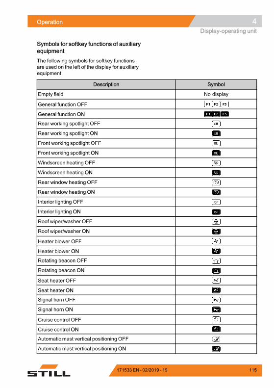
Operation 4Display-operating unit
Symbols for softkey functions of auxiliaryequipmentThe following symbols for softkey functionsare used on the left of the display for auxiliaryequipment:
Description Symbol
Empty field No display
General function OFF
General function ON
Rear working spotlight OFF
Rear working spotlight ON
Front working spotlight OFF
Front working spotlight ON
Windscreen heating OFF
Windscreen heating ON
Rear window heating OFF
Rear window heating ON
Interior lighting OFF
Interior lighting ON
Roof wiper/washer OFF
Roof wiper/washer ON
Heater blower OFF
Heater blower ON
Rotating beacon OFF
Rotating beacon ON
Seat heater OFF
Seat heater ON
Signal horn OFF
Signal horn ON
Cruise control OFF
Cruise control ON
Automatic mast vertical positioning OFF
Automatic mast vertical positioning ON
171533 EN - 02/2019 - 19 115
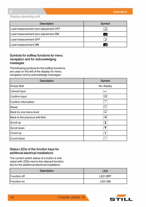
4 OperationDisplay-operating unit
Description Symbol
Load measurement zero adjustment OFF
Load measurement zero adjustment ON
Load measurement OFF
Load measurement ON.
Symbols for softkey functions for menunavigation and for acknowledgingmessagesThe following symbols for the softkey functionsare used on the left of the display for menunavigation and to acknowledge messages:
Description Symbol
Empty field No display
Cancel input
Confirm input
Confirm information
Reset
Back by one menu level
Back to the previous edit field
Scroll up
Scroll down
Count up
Count down.
Status LEDs of the function keys foradditional electrical installationsThe current switch status of a button is indi-cated with LEDs next to the relevant functionkey for the additional electrical installation.
Description LED
Function off LED OFF
Function on LED ON.
116 171533 EN - 02/2019 - 19
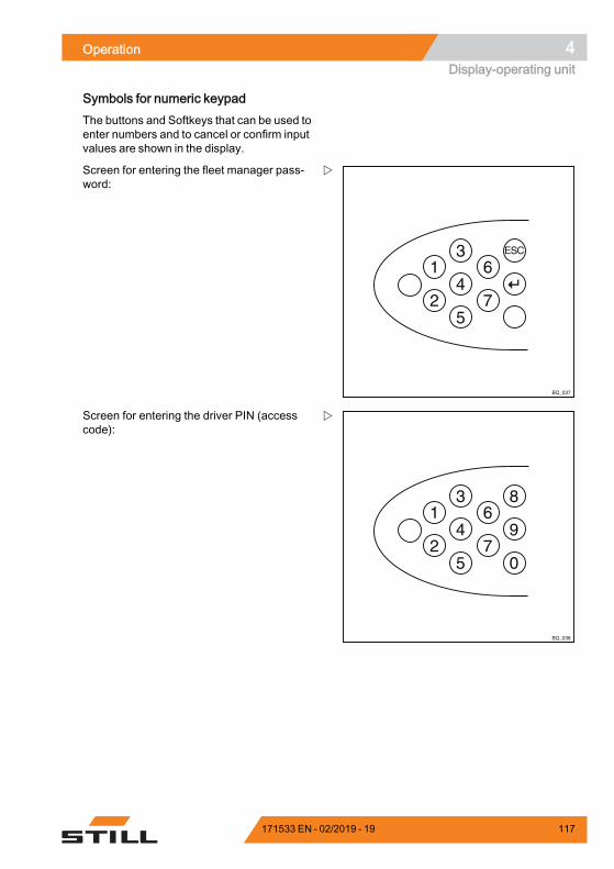
Operation 4Display-operating unit
Symbols for numeric keypadThe buttons and Softkeys that can be used toenter numbers and to cancel or confirm inputvalues are shown in the display.
BQ_037
1
2
6
7
3
4
5
ESC
Screen for entering the fleet manager pass-word:
1
2
6
7
3
4
5
8
9
0
BQ_038
Screen for entering the driver PIN (accesscode):
171533 EN - 02/2019 - 19 117
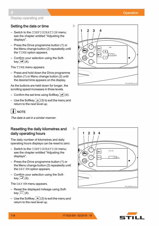
4 OperationDisplay-operating unit
8
9
0
6
7
4
3
5
7312_003-054_en_V3
1 2 3 4Setting the date or time– Switch to the CONFIGURATIONmenu;see the chapter entitled "Adjusting thedisplays".
– Press the Drive programme button (1) orthe Menu change button (2) repeatedly untilthe TIME option appears.
– Confirm your selection using the Soft-key (4).
The TIMEmenu appears.
– Press and hold down the Drive programmebutton (1) or Menu change button (2) untilthe desired time appears on the display.
As the buttons are held down for longer, thescrolling speed increases in three levels.
– Confirm the set time using Softkey (4).
– Use the Softkey (3) to exit themenu andreturn to the next level up.
NOTE
The date is set in a similar manner.
8
9
0
6
7
4
3
5
7312_003-055_en_V4
1 2 3 4Resetting the daily kilometres anddaily operating hoursThe daily number of kilometres and dailyoperating hours displays can be reset to zero:
– Switch to the CONFIGURATIONmenu;see the chapter entitled "Adjusting thedisplays".
– Press the Drive programme button (1) orthe Menu change button (2) repeatedly untilthe DAY KM option appears.
– Confirm your selection using the Soft-key (4).
The DAY KMmenu appears.
– Reset the displayed mileage using Soft-key (4).
– Use the Softkey (3) to exit themenu andreturn to the next level up.
118 171533 EN - 02/2019 - 19
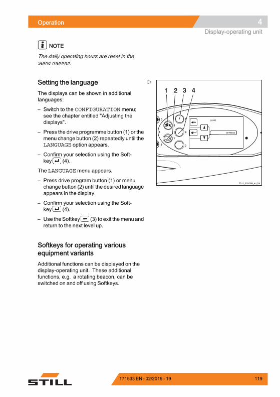
Operation 4Display-operating unit
NOTE
The daily operating hours are reset in thesame manner.
8
9
0
6
7
4
3
5
7312_003-058_en_V4
1 2 3 4Setting the languageThe displays can be shown in additionallanguages:
– Switch to the CONFIGURATIONmenu;see the chapter entitled "Adjusting thedisplays".
– Press the drive programme button (1) or themenu change button (2) repeatedly until theLANGUAGE option appears.
– Confirm your selection using the Soft-key (4).
The LANGUAGEmenu appears.
– Press drive program button (1) or menuchangebutton (2) until the desired languageappears in the display.
– Confirm your selection using the Soft-key (4).
– Use the Softkey (3) to exit themenu andreturn to the next level up.
Softkeys for operating variousequipment variantsAdditional functions can be displayed on thedisplay-operating unit. These additionalfunctions, e.g. a rotating beacon, can beswitched on and off using Softkeys.
171533 EN - 02/2019 - 19 119
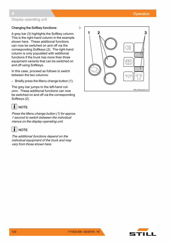
4 OperationDisplay-operating unit
1 2 3
ABE_Softkeytasten_V2
Changing the Softkey functions:
A grey bar (3) highlights the Softkey column.This is the right-hand column in the exampleshown here. These additional functionscan now be switched on and off via thecorresponding Softkeys (2). The right-handcolumn is only populated with additionalfunctions if the truck has more than threeequipment variants that can be switched onand off using Softkeys.
In this case, proceed as follows to switchbetween the two columns:
– Briefly press the Menu change button (1).
The grey bar jumps to the left-hand col-umn. These additional functions can nowbe switched on and off via the correspondingSoftkeys (2).
NOTE
Press the Menu change button (1) for approx.1 second to switch between the individualmenus on the display-operating unit.
NOTE
The additional functions depend on theindividual equipment of the truck and mayvary from those shown here.
120 171533 EN - 02/2019 - 19
Operation 4Blue-Q efficiency mode
Blue-Q efficiency modeFunctional descriptionThe Blue-Q efficiency mode affects both thedrive unit and the activation of the additionalconsumers, and reduces the truck's energyconsumption.
If the efficiency mode has been activated, theacceleration behaviour of the truck changes tomake acceleration more moderate.
When travelling at low speeds—normallywhen manoeuvring—no reduction is notice-able despite the activated efficiency mode.For moderate speeds of at least approx.7 km/h, acceleration is gentler. Therefore,on distances of up to approx. 40 m, lowerspeeds are reached than would be the case ifthe efficiency mode was not activated.
Blue-Q has no influence on:• Maximum speed• Climbing capability• Traction• Braking characteristics
NOTE
The Blue-Q efficiency mode can be swit-ched on and off in the STANDARD and FI-XED-FLEX operating modes. If the FIXEDoperating mode is configured in the displayoperating unit, the Blue-Q button has no func-tion and the Blue-Q efficiency mode is swit-ched on permanently; see also chapter "Con-figuring Blue-Q efficiency mode".
171533 EN - 02/2019 - 19 121
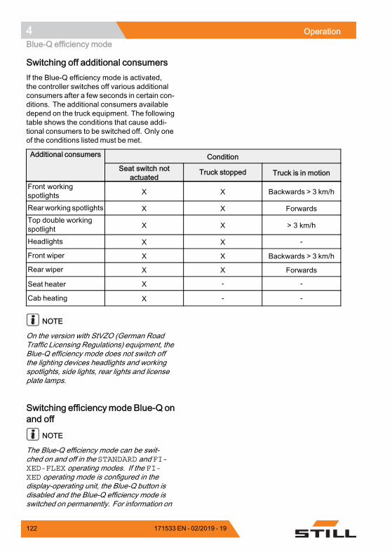
4 OperationBlue-Q efficiency mode
Switching off additional consumersIf the Blue-Q efficiency mode is activated,the controller switches off various additionalconsumers after a few seconds in certain con-ditions. The additional consumers availabledepend on the truck equipment. The followingtable shows the conditions that cause addi-tional consumers to be switched off. Only oneof the conditions listed must be met.
ConditionAdditional consumers
Seat switch notactuated
Truck stopped Truck is in motion
Front workingspotlights X X Backwards > 3 km/h
Rearworking spotlights X X ForwardsTop double workingspotlight X X > 3 km/h
Headlights X X -
Front wiper X X Backwards > 3 km/h
Rear wiper X X Forwards
Seat heater X - -
Cab heating X - -
NOTE
On the version with StVZO (German RoadTraffic Licensing Regulations) equipment, theBlue-Q efficiency mode does not switch offthe lighting devices headlights and workingspotlights, side lights, rear lights and licenseplate lamps.
Switching efficiencymode Blue-Q onand off
NOTE
The Blue-Q efficiency mode can be swit-ched on and off in the STANDARD and FI-XED-FLEX operating modes. If the FI-XED operating mode is configured in thedisplay-operating unit, the Blue-Q button isdisabled and the Blue-Q efficiency mode isswitched on permanently. For information on
122 171533 EN - 02/2019 - 19
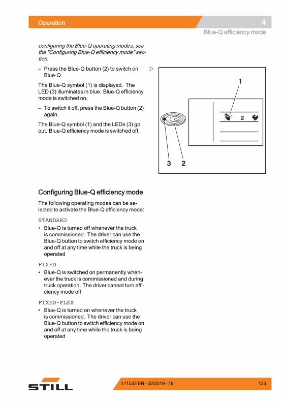
Operation 4Blue-Q efficiency mode
configuring the Blue-Q operating modes, seethe "Configuring Blue-Q efficiency mode" sec-tion.
2
2
1
3
– Press the Blue-Q button (2) to switch onBlue-Q.
The Blue-Q symbol (1) is displayed. TheLED (3) illuminates in blue. Blue-Q efficiencymode is switched on.
– To switch it off, press the Blue-Q button (2)again.
The Blue-Q symbol (1) and the LEDs (3) goout. Blue-Q efficiency mode is switched off.
Configuring Blue-Q efficiency modeThe following operating modes can be se-lected to activate the Blue-Q efficiency mode:
STANDARD
• Blue-Q is turned off whenever the truckis commissioned. The driver can use theBlue-Q button to switch efficiency mode onand off at any time while the truck is beingoperated
FIXED
• Blue-Q is switched on permanently when-ever the truck is commissioned and duringtruck operation. The driver cannot turn effi-ciency mode off
FIXED-FLEX
• Blue-Q is turned on whenever the truckis commissioned. The driver can use theBlue-Q button to switch efficiency mode onand off at any time while the truck is beingoperated
171533 EN - 02/2019 - 19 123
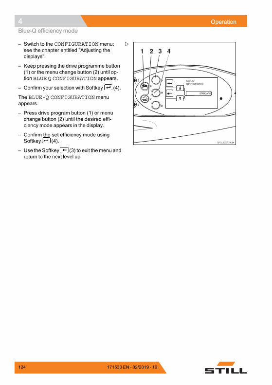
4 OperationBlue-Q efficiency mode
8
9
0
6
7
4
3
5
7312_003-179_en
1 2 3 4– Switch to the CONFIGURATIONmenu;see the chapter entitled "Adjusting thedisplays".
– Keep pressing the drive programme button(1) or the menu change button (2) until op-tion BLUE Q CONFIGURATION appears.
– Confirm your selection with Softkey (4).
The BLUE-Q CONFIGURATION menuappears.
– Press drive program button (1) or menuchange button (2) until the desired effi-ciency mode appears in the display.
– Confirm the set efficiency mode usingSoftkey (4).
– Use the Softkey (3) to exit themenu andreturn to the next level up.
124 171533 EN - 02/2019 - 19
Operation 4Driving
DrivingSafety regulations when driving
Driving conductThe driver must follow the public rules of theroad when driving in company traffic.
The speed must be appropriate to the localconditions.
For example, the driver must drive slowlyaround corners, in tight passageways, whendriving through swing-doors, at blind spots, oron uneven surfaces.
The driver must always maintain a safebraking distance from vehicles and persons infront, and must always have the truck undercontrol. Stopping suddenly, turning quicklyand overtaking at dangerous or blind spotsmust be avoided.
– Initial driving practice must be carried out inan empty space or on a clear roadway.
The following are forbidden during driving:• Allowing arms and legs to hang outside thetruck
• Leaning the body over the outer contour ofthe truck
• Climbing out of the truck• Moving the driver's seat• Adjusting the steering column• Releasing the seat belt• Disabling the restraint system• Raising the load higher than 300 mmabove the ground (with the exceptionof manoeuvring processes during theplacement into stock/removal from stockof loads)
• Using electronic devices, for exampleradios, mobile phones etc.
171533 EN - 02/2019 - 19 125
4 OperationDriving
WARNINGThe use of multimedia and communication equip-ment as well as playing these devices at an exces-sive volume during travel or when handling loadscan affect the operator's attention. There is a risk ofaccident!– Do not use devices during travel or when hand-
ling loads.– Set the volume so that warning signals can still
be heard.
WARNINGIn areas where use of mobile phones is prohibited,use of a mobile phone or radio telephone is notpermitted.– Switch off the devices.
Visibility when drivingThe driver must look in the drive direction andhave a sufficient view of the driving lane.
Particularly for reverse travel, the driver mustbe sure that the driving lane is clear.
When transporting goods that impair visibility,the driver must drive the truck in reverse.
If this is not possible, a second person actingas a guide must walk in front of the truck.
In this case the driver must only move atwalking pace and with extra care. The truckmust be stopped immediately if eye contactwith the guide is lost.
Rear-view mirrors are only to be used forobserving the road area behind the truck andnot for reverse travel. If visual aids (mirror,monitor) are necessary to achieve sufficientvisibility, it is necessary to practise using them.For reverse travel using visual aids, extra careshould be taken.
When using attachments, special conditionsapply; see the chapter entitled "Fitting attach-ments".
Any glass (variant, e.g. windscreen) andmirrors must always be clean and free of ice.
126 171533 EN - 02/2019 - 19
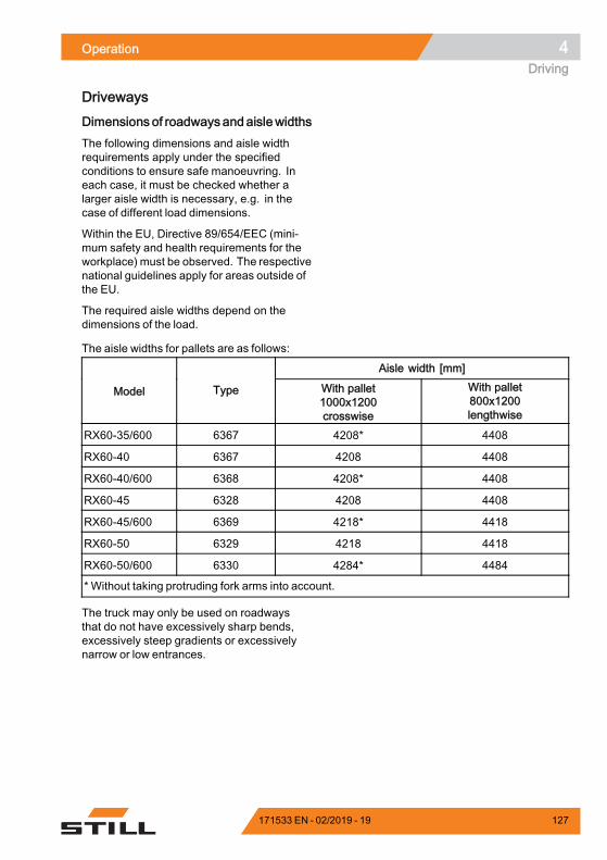
Operation 4Driving
Driveways
Dimensions of roadwaysandaislewidthsThe following dimensions and aisle widthrequirements apply under the specifiedconditions to ensure safe manoeuvring. Ineach case, it must be checked whether alarger aisle width is necessary, e.g. in thecase of different load dimensions.
Within the EU, Directive 89/654/EEC (mini-mum safety and health requirements for theworkplace) must be observed. The respectivenational guidelines apply for areas outside ofthe EU.
The required aisle widths depend on thedimensions of the load.
The aisle widths for pallets are as follows:
Aisle width [mm]
Model Type With pallet1000x1200crosswise
With pallet800x1200lengthwise
RX60-35/600 6367 4208* 4408
RX60-40 6367 4208 4408
RX60-40/600 6368 4208* 4408
RX60-45 6328 4208 4408
RX60-45/600 6369 4218* 4418
RX60-50 6329 4218 4418
RX60-50/600 6330 4284* 4484
* Without taking protruding fork arms into account.
The truck may only be used on roadwaysthat do not have excessively sharp bends,excessively steep gradients or excessivelynarrow or low entrances.
171533 EN - 02/2019 - 19 127
4 OperationDriving
Driving on ascending and descendinggradients
WARNINGRisk of accident due to the drive unit switching off!Driving up and down longer gradients may causethe drive unit to overheat and switch off. The truckwill then no longer decelerate when the acceleratorpedal is released and will coast.Driving up and down longer gradients greater than15% is not permitted due to the minimum specifiedbraking values. The climbing capability valuesgiven below only apply to overcoming obstacles onthe roadway and to short differences in level, e.g.ramps.– Consult the authorised service centre before
driving on long ascending and descendinggradients greater than 15%.
CAUTIONRisk of component damage due to reduced groundclearance with a hydraulic battery carrier (variant)!Trucks fitted with a hydraulic battery carrier (va-riant) have a reduced ground clearance, and thepermitted climbing capability is therefore reduced.The ground clearance with standard tyres is redu-ced to 70.5 mm. The maximum wear limit of thetyres may not be reached.– Check the angle of ramps!
NOTE
The values specified in the "Maximum clim-bing capability" table can be used only to com-pare the performance of forklift trucks in thesame category. The specified values in noway represent the normal daily operating con-ditions.
Trucks can theoretically be driven on theascending and descending gradients in thefollowing table.
128 171533 EN - 02/2019 - 19
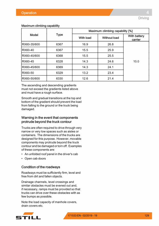
Operation 4Driving
Maximum climbing capability
Maximum climbing capability [%]Model Type
With load Without load With batterycarrier
RX60-35/600 6367 16.9 26.8
RX60-40 6367 15.5 25.9
RX60-40/600 6368 15.5 25.5
RX60-45 6328 14.3 24.6
RX60-45/600 6369 14.3 24.1
RX60-50 6329 13.2 23.4
RX60-50/600 6330 12.6 21.4
10.0
The ascending and descending gradientsmust not exceed the gradients listed aboveand must have a rough surface.
Smooth and gradual transitions at the top andbottom of the gradient should prevent the loadfrom falling to the ground or the truck beingdamaged.
Warning in the event that componentsprotrude beyond the truck contour
Trucks are often required to drive through verynarrow or very low spaces such as aisles orcontainers. The dimensions of the trucks aredesigned for this purpose. However, movablecomponents may protrude beyond the truckcontour and bedamaged or torn off. Examplesof these components are:• An unfolded roof panel in the driver's cab• Open cab doors
Condition of the roadwaysRoadways must be sufficiently firm, level andfree from dirt and fallen objects.
Drainage channels, level crossings andsimilar obstacles must be evened out and,if necessary, ramps must be provided so thattrucks can drive over these obstacles with asfew bumps as possible.
Note the load capacity of manhole covers,drain covers etc.
171533 EN - 02/2019 - 19 129
4 OperationDriving
There must be sufficient distance between thehighest points of the truck or the load and thefixed elements of the surrounding area. Theheight is based on the overall height of the liftmast and the dimensions of the load; see thechapter entitled "Technical data".
Rules for roadways and the working areaIt is only permitted to drive on routes autho-rised for traffic by the operating company or itsrepresentatives. Traffic routes must be freeof obstacles. The load may only be set downand stored in the designated locations. Theoperating company and its representativesmust ensure that unauthorised third parties donot enter the working area.
NOTE
Please note the definition of "operating com-pany" in the sense of responsible persons!
Hazard areasHazard areas on the roadways must bemarked by standard traffic signs or, if nec-essary, by additional warning signs.
Setting the drive programsThe driving and braking characteristics of thedrive can be set on the display and operatingunit.
130 171533 EN - 02/2019 - 19
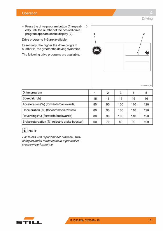
Operation 4Driving
6311_003-028_V2
1
1 2
– Press the drive program button (1) repeat-edly until the number of the desired driveprogram appears on the display (2).
Drive programs 1–5 are available.
Essentially, the higher the drive programnumber is, the greater the driving dynamics.
The following drive programs are available:
Drive program 1 2 3 4 5
Speed (km/h) 16 16 16 16 16
Acceleration (%) (forwards/backwards) 80 90 100 110 120
Deceleration (%) (forwards/backwards) 80 90 100 110 120
Reversing (%) (forwards/backwards) 80 90 100 110 120
Brake retardation (%) (electric brake booster) 60 70 80 90 100
NOTE
For trucks with "sprint mode" (variant), swit-ching on sprint mode leads to a general in-crease in performance.
171533 EN - 02/2019 - 19 131
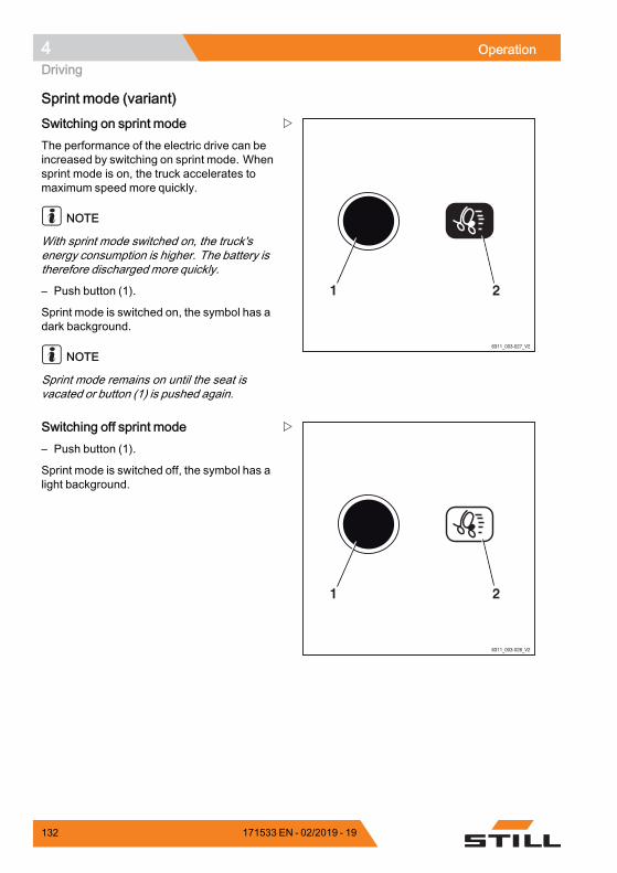
4 OperationDriving
Sprint mode (variant)
6311_003-027_V2
21
Switching on sprint modeThe performance of the electric drive can beincreased by switching on sprint mode. Whensprint mode is on, the truck accelerates tomaximum speed more quickly.
NOTE
With sprint mode switched on, the truck'senergy consumption is higher. The battery istherefore discharged more quickly.
– Push button (1).
Sprint mode is switched on, the symbol has adark background.
NOTE
Sprint mode remains on until the seat isvacated or button (1) is pushed again.
6311_003-026_V2
21
Switching off sprint mode– Push button (1).
Sprint mode is switched off, the symbol has alight background.
132 171533 EN - 02/2019 - 19
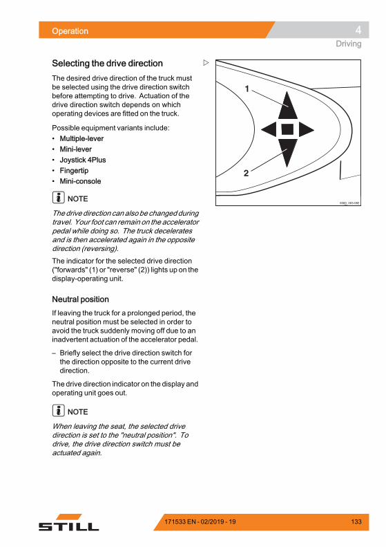
Operation 4Driving
5060_003-082
1
2
Selecting the drive directionThe desired drive direction of the truck mustbe selected using the drive direction switchbefore attempting to drive. Actuation of thedrive direction switch depends on whichoperating devices are fitted on the truck.
Possible equipment variants include:• Multiple-lever• Mini-lever• Joystick 4Plus• Fingertip• Mini-console
NOTE
Thedrive direction canalsobechangedduringtravel. Your foot can remain on the acceleratorpedal while doing so. The truck deceleratesand is then accelerated again in the oppositedirection (reversing).The indicator for the selected drive direction("forwards" (1) or "reverse" (2)) lights up on thedisplay-operating unit.
Neutral positionIf leaving the truck for a prolonged period, theneutral position must be selected in order toavoid the truck suddenly moving off due to aninadvertent actuation of the accelerator pedal.
– Briefly select the drive direction switch forthe direction opposite to the current drivedirection.
The drive direction indicator on the display andoperating unit goes out.
NOTE
When leaving the seat, the selected drivedirection is set to the "neutral position". Todrive, the drive direction switch must beactuated again.
171533 EN - 02/2019 - 19 133
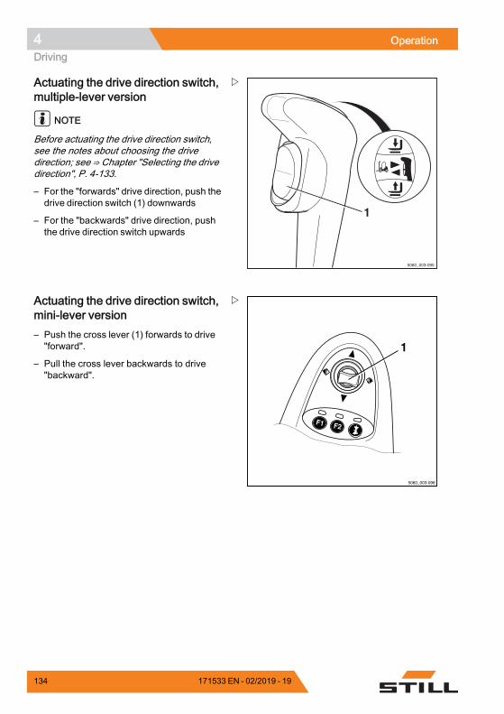
4 OperationDriving
1
5060_003-095
Actuating the drive direction switch,multiple-lever version
NOTE
Before actuating the drive direction switch,see the notes about choosing the drivedirection; see ⇒ Chapter "Selecting the drivedirection", P. 4-133.
– For the "forwards" drive direction, push thedrive direction switch (1) downwards
– For the "backwards" drive direction, pushthe drive direction switch upwards
5060_003-096
F1 F2
1
Actuating the drive direction switch,mini-lever version– Push the cross lever (1) forwards to drive"forward".
– Pull the cross lever backwards to drive"backward".
134 171533 EN - 02/2019 - 19
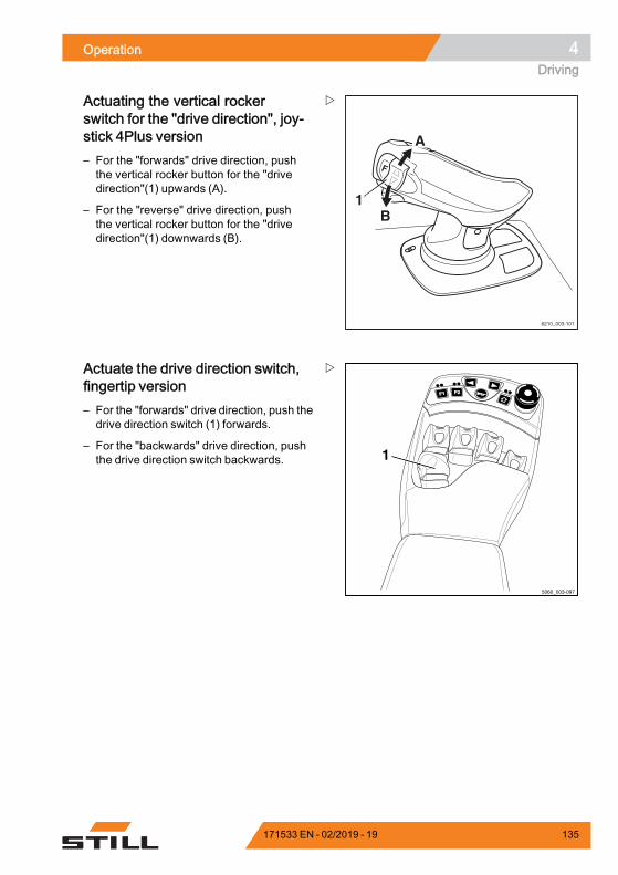
Operation 4Driving
1
6210_003-101
A
B
Actuating the vertical rockerswitch for the "drive direction", joy-stick 4Plus version– For the "forwards" drive direction, pushthe vertical rocker button for the "drivedirection"(1) upwards (A).
– For the "reverse" drive direction, pushthe vertical rocker button for the "drivedirection"(1) downwards (B).
F1F1 F2F2
5060_003-097
1
Actuate the drive direction switch,fingertip version– For the "forwards" drive direction, push thedrive direction switch (1) forwards.
– For the "backwards" drive direction, pushthe drive direction switch backwards.
171533 EN - 02/2019 - 19 135
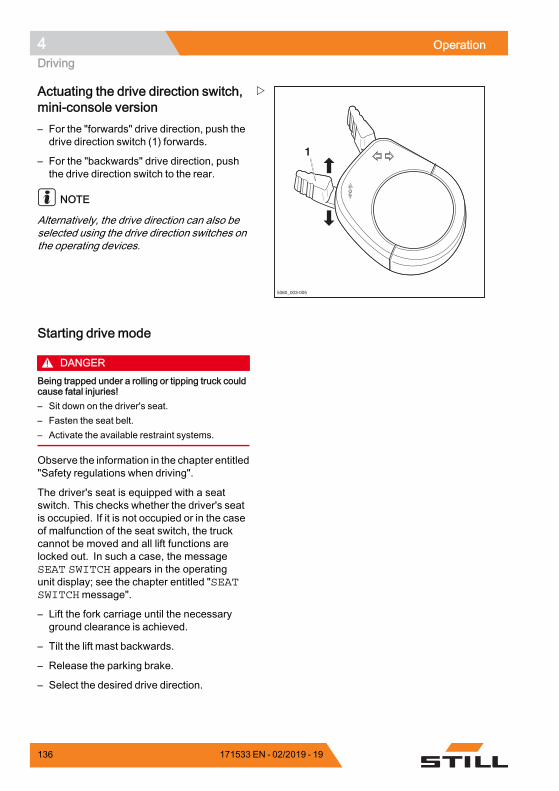
4 OperationDriving
5060_003-005
1
Actuating the drive direction switch,mini-console version– For the "forwards" drive direction, push thedrive direction switch (1) forwards.
– For the "backwards" drive direction, pushthe drive direction switch to the rear.
NOTE
Alternatively, the drive direction can also beselected using the drive direction switches onthe operating devices.
Starting drive mode
DANGERBeing trapped under a rolling or tipping truck couldcause fatal injuries!– Sit down on the driver's seat.– Fasten the seat belt.– Activate the available restraint systems.
Observe the information in the chapter entitled"Safety regulations when driving".
The driver's seat is equipped with a seatswitch. This checks whether the driver's seatis occupied. If it is not occupied or in the caseof malfunction of the seat switch, the truckcannot be moved and all lift functions arelocked out. In such a case, the messageSEAT SWITCH appears in the operatingunit display; see the chapter entitled "SEATSWITCHmessage".
– Lift the fork carriage until the necessaryground clearance is achieved.
– Tilt the lift mast backwards.
– Release the parking brake.
– Select the desired drive direction.
136 171533 EN - 02/2019 - 19
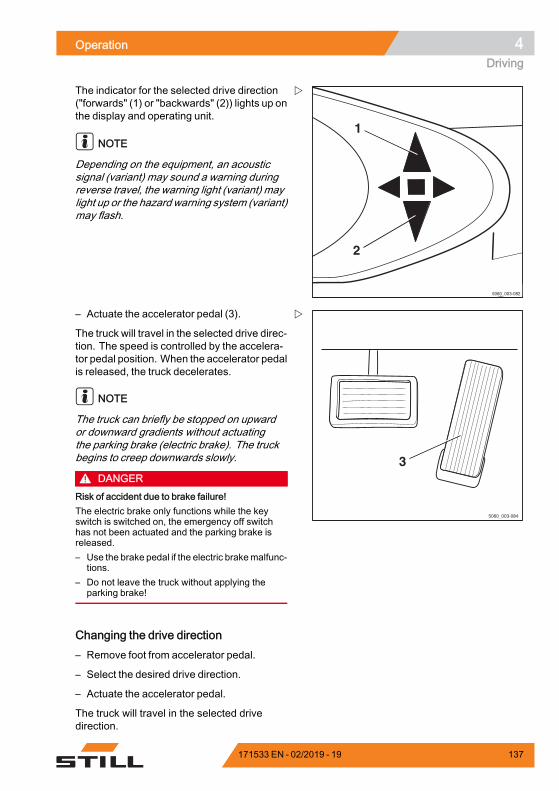
Operation 4Driving
5060_003-082
1
2
The indicator for the selected drive direction("forwards" (1) or "backwards" (2)) lights up onthe display and operating unit.
NOTE
Depending on the equipment, an acousticsignal (variant) may sound a warning duringreverse travel, the warning light (variant) maylight up or the hazard warning system (variant)may flash.
3
5060_003-084
– Actuate the accelerator pedal (3).
The truck will travel in the selected drive direc-tion. The speed is controlled by the accelera-tor pedal position. When the accelerator pedalis released, the truck decelerates.
NOTE
The truck can briefly be stopped on upwardor downward gradients without actuatingthe parking brake (electric brake). The truckbegins to creep downwards slowly.
DANGERRisk of accident due to brake failure!The electric brake only functions while the keyswitch is switched on, the emergency off switchhas not been actuated and the parking brake isreleased.– Use the brake pedal if the electric brakemalfunc-
tions.– Do not leave the truck without applying the
parking brake!
Changing the drive direction– Remove foot from accelerator pedal.
– Select the desired drive direction.
– Actuate the accelerator pedal.
The truck will travel in the selected drivedirection.
171533 EN - 02/2019 - 19 137
4 OperationDriving
NOTE
Thedrivedirection canalso be changedduringtravel. Your foot can remain on the acceleratorpedal while doing so. The truck deceleratesand is then accelerated again in the oppositedirection (reversing).
NOTE
In the event of an electrical fault with theaccelerator the drive unit is shut down. Theelectrical brake (service brake) causes thetruck to decelerate. The truck cannot be drivenagain until the accelerator pedal has beenreleased and then actuated again, providedthe electrical fault has been corrected. If thetruck still cannot be operated, park it securelyand contact your authorised service centre.
Starting drive mode, dual-pedalversion (variant)
DANGERBeing trapped under a rolling or tipping truck couldcause fatal injuries.– Sit down on the driver's seat.– Fasten the seat belt.– Activate the available restraint systems.
Observe the information in the chapter entitledSafety regulations when driving.
The driver's seat is equipped with a seatswitch. This checks whether the driver'sseat is occupied. If it is not occupied or inthe case of malfunction of the seat switch, thetruck cannot be moved and all lifting functionsare locked. In this situation, the messageSEAT SWITCH appears on the operating unitdisplay.
– Lift the fork carriage until the necessaryground clearance is achieved.
– Tilt the lift mast backwards.
– Release the parking brake.
138 171533 EN - 02/2019 - 19
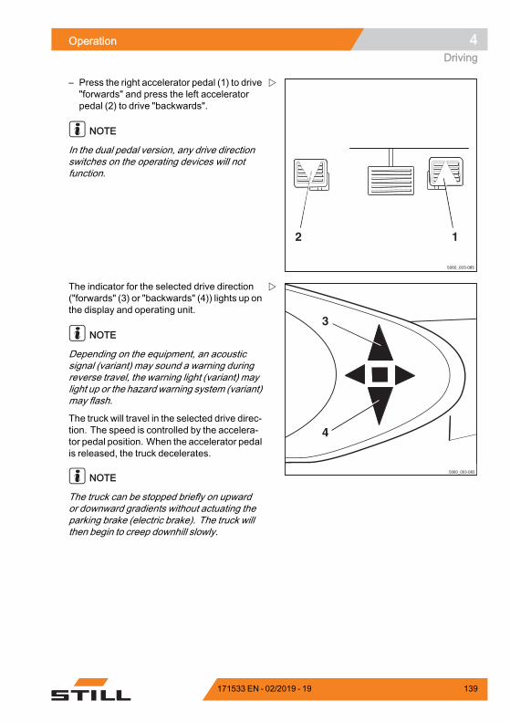
Operation 4Driving
5060_003-085
2 1
– Press the right accelerator pedal (1) to drive"forwards" and press the left acceleratorpedal (2) to drive "backwards".
NOTE
In the dual pedal version, any drive directionswitches on the operating devices will notfunction.
5060_003-083
3
4
The indicator for the selected drive direction("forwards" (3) or "backwards" (4)) lights up onthe display and operating unit.
NOTE
Depending on the equipment, an acousticsignal (variant) may sound a warning duringreverse travel, the warning light (variant) maylight up or the hazard warning system (variant)may flash.
The truck will travel in the selected drive direc-tion. The speed is controlled by the accelera-tor pedal position. When the accelerator pedalis released, the truck decelerates.
NOTE
The truck can be stopped briefly on upwardor downward gradients without actuating theparking brake (electric brake). The truck willthen begin to creep downhill slowly.
171533 EN - 02/2019 - 19 139
4 OperationDriving
DANGERRisk of accident due to brake failure!The electric brake only functions while the keyswitch is switched on, the emergency off switchhas not been actuated and the parking brake isreleased.– Use the brake pedal if the electric brakemalfunc-
tions.– Do not leave the truck without applying the
parking brake!
Changing the drive direction– Remove foot from actuated acceleratorpedal.
– Actuate the accelerator pedal for theopposite direction.
The truck will travel in the selected drivedirection.
NOTE
In the event of an electrical fault with theaccelerator the drive unit is shut down. Theelectric brake (service brake) causes the truckto decelerate. The truck cannot be drivenagain until the accelerator pedal has beenreleased and then actuated again, providedthat the electrical fault has been corrected.If the truck still cannot be operated, park itsecurely and contact your authorised servicecentre.
140 171533 EN - 02/2019 - 19
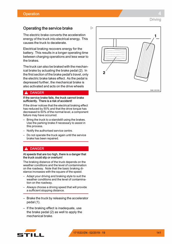
Operation 4Driving
1
2
5060_003-006
Operating the service brakeThe electric brake converts the accelerationenergy of the truck into electrical energy. Thiscauses the truck to decelerate.
Electrical braking recovers energy for thebattery. This results in a longer operating timebetween charging operations and less wear tothe brakes.
The truck can also be brakedwith themechan-ical brake by actuating the brake pedal (2). Inthe first section of the brake pedal's travel, onlythe electric brake takes effect. As the pedal isdepressed further, the mechanical brake isalso activated and acts on the drive wheels
DANGERIf the service brake fails, the truck cannot brakesufficiently. There is a risk of accident!If the driver notices that the electrical braking effecthas reduced by 50% and that the drive torque hasdecreased to 50% of the normal level, a componentfailure may have occurred.– Bring the truck to a standstill using the brakes.
Use the parking brake if necessary to assist inthis process.
– Notify the authorised service centre.– Do not operate the truck again until the service
brake has been repaired.
DANGERAt speeds that are too high, there is a danger thatthe truck could slip or overturn!The braking distance of the truck depends on theweather conditions and the level of contaminationon the roadway. Note that the basic braking di-stance increases with the square of the speed.– Adapt your driving and braking style to suit the
weather conditions and the level of contamina-tion on the roadway.
– Always choose a driving speed that will providea sufficient stopping distance.
– Brake the truck by releasing the acceleratorpedal (1).
– If the braking effect is inadequate, usethe brake pedal (2) as well to apply themechanical brake.
171533 EN - 02/2019 - 19 141
4 OperationDriving
Parking brakeOperation of the parking brake depends onwhich parking brake the truck is fitted with.
Possible equipment variants are as follows:• Mechanical parking brake; see ⇒ Chap-ter "Actuating the mechanical parkingbrake", P. 4-142
• Electric parking brake; see ⇒ Chapter "Ac-tuate the electric parking brake", P. 4-144
Actuating the mechanical parkingbrake
DANGERThere is a risk of being run over if the truck rollsaway, and therefore a danger to life.– The truck must not be parked on a slope.– In emergencies, secure with wedges on the side
facing downhill.– Only leave the truck when the parking brake is
applied.
NOTE
Once the parking brake is released, thepreviously selected drive direction is retainedand is shown on the drive direction indicator.
NOTE
If you operate the accelerator pedal while theparking brake is applied and a drive directionis selected, the message PARKING BRAKEappears in the display.
142 171533 EN - 02/2019 - 19
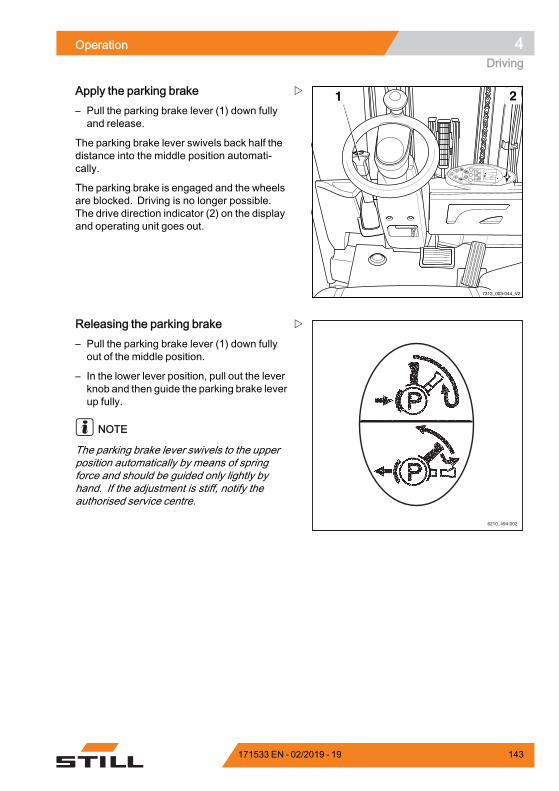
Operation 4Driving
8
9
6
72
0
13
5
%75
h
2
234,712:15
1 2
7312_003-044_V2
Apply the parking brake– Pull the parking brake lever (1) down fullyand release.
The parking brake lever swivels back half thedistance into the middle position automati-cally.
The parking brake is engaged and the wheelsare blocked. Driving is no longer possible.The drive direction indicator (2) on the displayand operating unit goes out.
6210_494-002
Releasing the parking brake– Pull the parking brake lever (1) down fullyout of the middle position.
– In the lower lever position, pull out the leverknob and then guide the parking brake leverup fully.
NOTE
The parking brake lever swivels to the upperposition automatically by means of springforce and should be guided only lightly byhand. If the adjustment is stiff, notify theauthorised service centre.
171533 EN - 02/2019 - 19 143
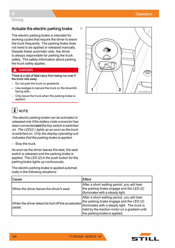
4 OperationDriving
6210_003-050_V421
Actuate the electric parking brakeThe electric parking brake is intended forworking cycles that require the driver to leavethe truck frequently. The parking brake doesnot need to be applied or released manually.Despite these automatic aids, the driveris always responsible for parking the trucksafely. The safety information about parkingthe truck safely applies.
DANGERThere is a risk of fatal injury from being run over ifthe truck rolls away.– Do not park the truck on gradients.– Use wedges to secure the truck on the downhill-
facing side.– Only leave the truck when the parking brake is
applied.
NOTE
The electric parking brake can be activated orreleased only if the batterymale connector hasbeen connectedand the key switch is switchedon. The LED(2.) lights up as soon as the truckis switched on. Only the display-operating unitindicates that the parking brake is applied.
– Stop the truck.
As soon as the driver leaves the seat, the seatswitch is released and the parking brake isapplied. The LED (2) in the push button for theparking brake lights up continuously.
The electric parking brake is applied automat-ically in the following situations:
Cause Effect
When the driver leaves the driver's seat:After a short waiting period, you will hearthe parking brake engage and the LED (2)illuminates with a steady light.
When the driver takes his foot off the acceleratorpedal:
After a short waiting period, you will hearthe parking brake engage and the LED (2)illuminates with a steady light. The truck isheld by the traction motor on a gradient untilthe parking brake is applied.
144 171533 EN - 02/2019 - 19
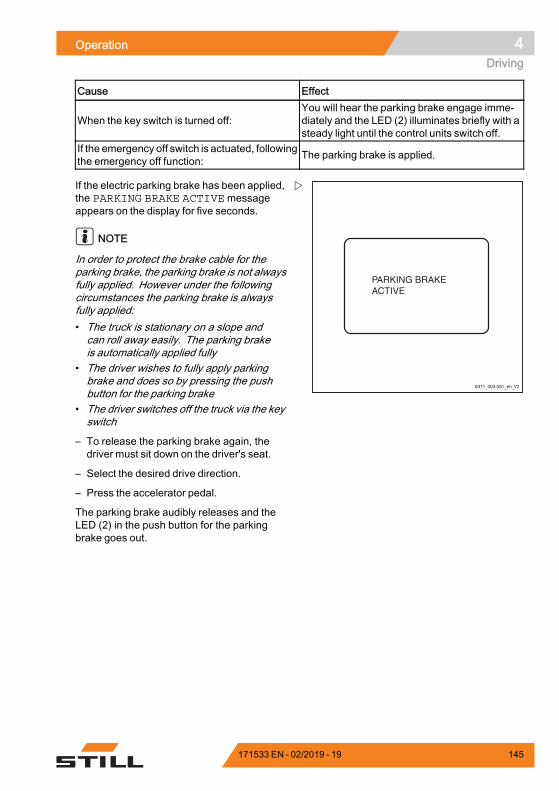
Operation 4Driving
Cause Effect
When the key switch is turned off:You will hear the parking brake engage imme-diately and the LED (2) illuminates briefly with asteady light until the control units switch off.
If the emergency off switch is actuated, followingthe emergency off function: The parking brake is applied.
6311_003-031_en_V2
If the electric parking brake has been applied,the PARKING BRAKE ACTIVEmessageappears on the display for five seconds.
NOTE
In order to protect the brake cable for theparking brake, the parking brake is not alwaysfully applied. However under the followingcircumstances the parking brake is alwaysfully applied:• The truck is stationary on a slope andcan roll away easily. The parking brakeis automatically applied fully
• The driver wishes to fully apply parkingbrake and does so by pressing the pushbutton for the parking brake
• The driver switches off the truck via the keyswitch
– To release the parking brake again, thedriver must sit down on the driver's seat.
– Select the desired drive direction.
– Press the accelerator pedal.
The parking brake audibly releases and theLED (2) in the push button for the parkingbrake goes out.
171533 EN - 02/2019 - 19 145
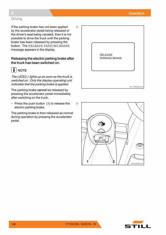
4 OperationDriving
6311_003-032_en_V2
If the parking brake has not been appliedby the accelerator pedal being released orthe driver's seat being vacated, then it is notpossible to drive the truck until the parkingbrake has been released by pressing thebutton. The RELEASE PARKING BRAKEmessage appears in the display.
Releasing the electric parking brake afterthe truck has been switched on.
NOTE
The LED(2.) lights up as soon as the truck isswitched on. Only the display-operating unitindicates that the parking brake is applied.
The parking brake cannot be released bypressing the accelerator pedal immediatelyafter switching on the truck.
6210_003-050_V421
– Press the push button (1) to release theelectric parking brake.
The parking brake is then released as normalduring operation by pressing the acceleratorpedal.
146 171533 EN - 02/2019 - 19
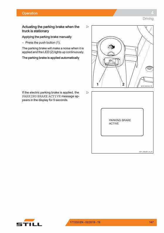
Operation 4Driving
6210_003-050_V421
Actuating the parking brake when thetruck is stationaryApplying the parking brake manually
– Press the push button (1).
The parking brake will make a noise when it isapplied and the LED (2) lights up continuously.
The parking brake is applied automatically
6311_003-031_en_V2
If the electric parking brake is applied, thePARKING BRAKE ACTIVE message ap-pears in the display for 5 seconds.
171533 EN - 02/2019 - 19 147
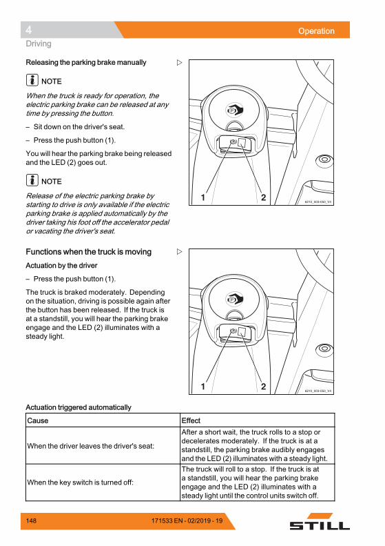
4 OperationDriving
6210_003-050_V421
Releasing the parking brake manually
NOTE
When the truck is ready for operation, theelectric parking brake can be released at anytime by pressing the button.
– Sit down on the driver's seat.
– Press the push button (1).
You will hear the parking brake being releasedand the LED (2) goes out.
NOTE
Release of the electric parking brake bystarting to drive is only available if the electricparking brake is applied automatically by thedriver taking his foot off the accelerator pedalor vacating the driver's seat.
6210_003-050_V421
Functions when the truck is movingActuation by the driver
– Press the push button (1).
The truck is braked moderately. Dependingon the situation, driving is possible again afterthe button has been released. If the truck isat a standstill, you will hear the parking brakeengage and the LED (2) illuminates with asteady light.
Actuation triggered automatically
Cause Effect
When the driver leaves the driver's seat:
After a short wait, the truck rolls to a stop ordecelerates moderately. If the truck is at astandstill, the parking brake audibly engagesand the LED (2) illuminates with a steady light.
When the key switch is turned off:
The truck will roll to a stop. If the truck is ata standstill, you will hear the parking brakeengage and the LED (2) illuminates with asteady light until the control units switch off.
148 171533 EN - 02/2019 - 19
Operation 4Driving
Cause Effect
If the emergency off switch is actuated, followingthe emergency off function:
The truck will roll to a stop. If the truck is ata standstill, you will hear the parking brakeengage and the LED (2) illuminates briefly witha steady light.
Automatic braking:
With the drive deactivated and the seat notoccupied or the truck being accelerated heavily,the parking brake is applied with moderatebraking force.
.
"Safe parking" functionThe "safe parking" function alerts the driverif he/she leaves the driver's seat or triesto switch off the truck without applying theparking brake. This function also prevents thetruck from being switched off when the parkingbrake is not applied.
The function is activated if the parking brakehas been applied but has not been appliedcorrectly as a result of a malfunction.
In both cases the function intervenes asfollows:
The function intervenes as follows:• If the driver tries to switch off the truckwhen the parking brake is not applied orthe parking brake is faulty, the PARKINGBRAKE: APPLY HANDBRAKE!messageappears on the display-operating unit.
• If the driver now leaves the truck withoutapplying the parking brake, a continuouswarning sound will also be emitted. Thewarning sound will stop if the driver returnsto his/her position in the truck or if the driverapplies the parking brake.
• If the parking brake cannot be applied, thetruck also cannot be switched off withouttaking other measures.
171533 EN - 02/2019 - 19 149
4 OperationDriving
DANGERRisk of fatal injury from being run over if the truckrolls away!If the parking brake is faulty, the truck must beparked safely and secured so that it cannot rollaway. To do this, strictly adhere to the followinginstructions:– Apply the parking brake manually. See the
section entitled "Emergency operation of theelectric parking brake".
– If necessary, use wheel chocks to prevent thetruck from rolling away.
– Have the parking brake repaired by an authori-sed service centre.
NOTE
If it is necessary to switch off a truck with afaulty parking brake, the "Switching off a truckwith a faulty electrical parking brake" sectionmust be observed. It is essential to secure thetruck to prevent it from rolling away.
Malfunctions in the electric parkingbrakeBefore leaving the truck, the driver must makesure that the electric parking brake is appliedproperly.
If the controller detects a malfunction in theelectric parking brake, the truck cannot beswitched off.
150 171533 EN - 02/2019 - 19
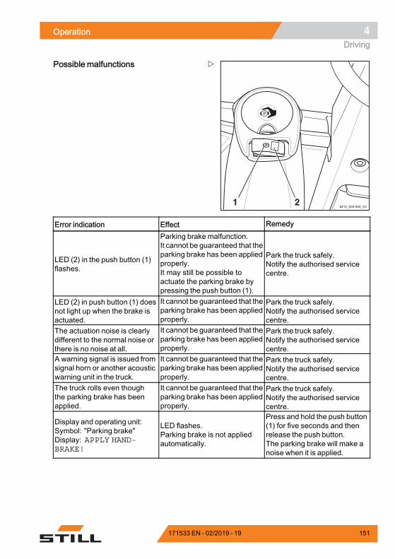
Operation 4Driving
6210_003-050_V421
Possible malfunctions
Error indication Effect Remedy
LED (2) in the push button (1)flashes.
Parking brake malfunction.It cannot be guaranteed that theparking brake has been appliedproperly.It may still be possible toactuate the parking brake bypressing the push button (1).
Park the truck safely.Notify the authorised servicecentre.
LED (2) in push button (1) doesnot light up when the brake isactuated.
It cannot be guaranteed that theparking brake has been appliedproperly.
Park the truck safely.Notify the authorised servicecentre.
The actuation noise is clearlydifferent to the normal noise orthere is no noise at all.
It cannot be guaranteed that theparking brake has been appliedproperly.
Park the truck safely.Notify the authorised servicecentre.
A warning signal is issued fromsignal horn or another acousticwarning unit in the truck.
It cannot be guaranteed that theparking brake has been appliedproperly.
Park the truck safely.Notify the authorised servicecentre.
The truck rolls even thoughthe parking brake has beenapplied.
It cannot be guaranteed that theparking brake has been appliedproperly.
Park the truck safely.Notify the authorised servicecentre.
Display and operating unit:Symbol: "Parking brake"Display: APPLY HAND-BRAKE!
LED flashes.Parking brake is not appliedautomatically.
Press and hold the push button(1) for five seconds and thenrelease the push button.The parking brake will make anoise when it is applied.
171533 EN - 02/2019 - 19 151
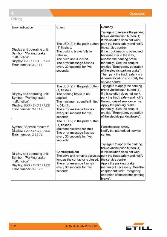
4 OperationDriving
Error indication Effect Remedy
Display and operating unit:Symbol: "Parking brakemalfunction"Display: PARKING BRAKEError number: X6511
The LED (2) in the push button(1) flashes.The parking brake fails torelease.The drive unit is locked.The error message flashesevery 30 seconds for fiveseconds.
Try again to release the parkingbrake via the push button (1).If this solution does not work,park the truck safely and notifythe service centre.If the truck needs to be movedbecause it is in the way,release the parking brakemanually. See the chapterentitled "Emergency operationof the electric parking brake".Then park the truck safely in adifferent location and notify theservice centre.
Display and operating unit:Symbol: "Parking brakemalfunction"Display: PARKING BRAKEError number: X6512
The LED (2) in the push button(1) flashes.The parking brake is notapplied.The maximum speed is limitedto 5 km/h.The error message flashesevery 30 seconds for fiveseconds.
Try again to apply the parkingbrake via the push button (1).If this solution does not work,park the truck safely and notifythe authorised service centre.Apply the parking brakemanually. See the chapterentitled "Emergency operationof the electric parking brake".
Symbol: "Service required"Display: PARKING BRAKEError number: X6501
The LED (2) in the push button(1) flashes.Maintenance time reached.The error message flashesevery 30 seconds for fiveseconds.
Park the truck safely.Notify the authorised servicecentre.
Display and operating unit:Symbol: "Parking brakemalfunction"Display: PARKING BRAKEError number: X6520
Control problemThe drive unit remains active aslong as the contactor is closed.The error message flashesevery 30 seconds for fiveseconds.
Try again to apply the parkingbrake via the push button (1).If this solution does not work,park the truck safely and notifythe service centre.Apply the parking brakemanually if necessary. See thechapter entitled "Emergencyoperation of the electric parkingbrake".
152 171533 EN - 02/2019 - 19
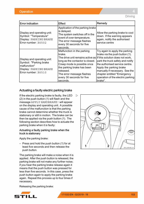
Operation 4Driving
Error indication Effect Remedy
Display and operating unit:Symbol: "Temperature"Display: PARKING BRAKEError number: X6502
Application of the parking brakeis delayed.The system switches off in theevent of over-temperature.The error message flashesevery 30 seconds for fiveseconds.
Allow the parking brake to cooldown. If the warning appearsagain, notify the authorisedservice centre
Display and operating unit:Symbol: "Parking brakemalfunction"Display: PARKING BRAKEError number: X6510
Malfunction in the parkingbrake.The drive unit remains active aslong as the contactor is closed.Creep mode is possible oncethe parking brake has beenreleased.The error message flashesevery 30 seconds for fiveseconds.
Try again to apply the parkingbrake via the push button (1).If this solution does not work,park the truck safely and notifythe authorised service centre.Apply the parking brakemanually if necessary. See thechapter entitled "Emergencyoperation of the electric parkingbrake".
.
Actuating a faulty electric parking brake
6210_003-050_V421
If the electric parking brake is faulty, the LED(2) in the push button (1) will flash and themessage APPLY HANDBRAKE! will appearon the display and operating unit. A possiblecause of the malfunction is that the parkingbrake cannot determine whether the truck isstationary or still in motion. The brake can bethen be applied via the push button (1). Thefollowing section describes how to actuate theparking brake when it is faulty:
Actuating a faulty parking brake when thetruck is stationary
Apply the parking brake:
– Press and hold the push button (1) for atleast five seconds and then release thepush button.
The parking brake will make a noise when it isapplied. After the push button is released, theparking brake will not make any further noise;if you hear the parking brake release again itmeans that the push button was pressed forless than five seconds. In this case, press thepush button again to apply the parking brakeagain. Repeat this process up to four times ifnecessary.
Releasing the parking brake:
171533 EN - 02/2019 - 19 153
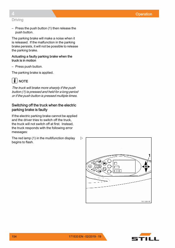
4 OperationDriving
– Press the push button (1) then release thepush button.
The parking brake will make a noise when itis released. If the malfunction in the parkingbrake persists, it will not be possible to releasethe parking brake.
Actuating a faulty parking brake when thetruck is in motion
– Press push button.
The parking brake is applied.
NOTE
The truck will brake more sharply if the pushbutton (1) is pressed and held for a long periodor if the push button is pressedmultiple times.
Switching off the truck when the electricparking brake is faultyIf the electric parking brake cannot be appliedand the driver tries to switch off the truck,the truck will not switch off at first. Instead,the truck responds with the following errormessages:
The red lamp (1) in the multifunction displaybegins to flash.
154 171533 EN - 02/2019 - 19
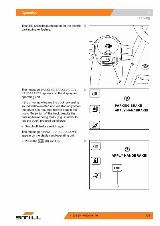
Operation 4Driving
The LED (2) in the push button for the electricparking brake flashes.
The message PARKING BRAKE APPLYHANDBRAKE! appears on the display andoperating unit.
If the driver now leaves the truck, a warningsound will be emitted and will stop only whenthe driver has resumed his/her seat in thetruck. To switch off the truck despite theparking brake being faulty (e.g. in order totow the truck) proceed as follows:
– Switch off the key switch again.
The message APPLY HANDBRAKE! willappear on the display and operating unit.
– Press the ESC (3) soft key.
171533 EN - 02/2019 - 19 155
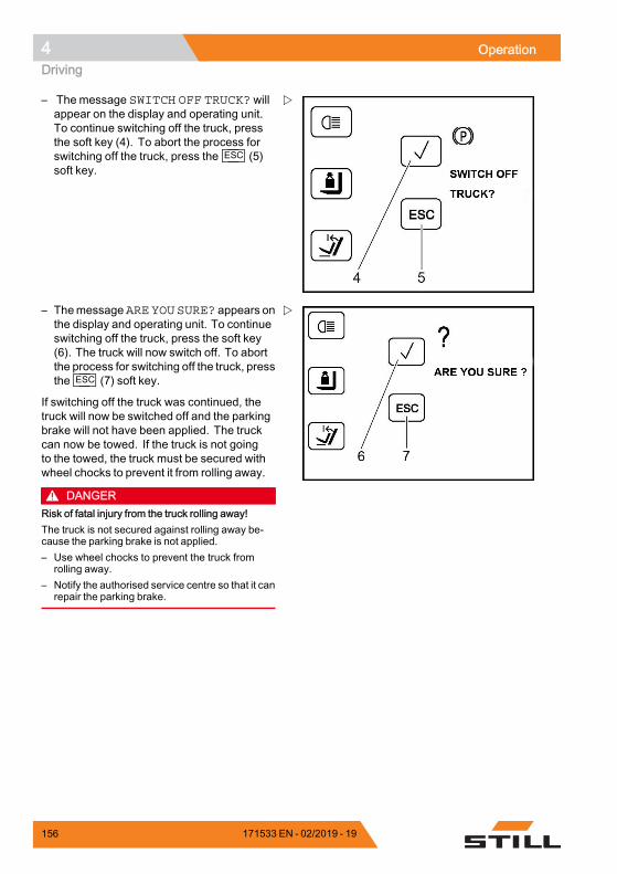
4 OperationDriving
– The message SWITCH OFF TRUCK? willappear on the display and operating unit.To continue switching off the truck, pressthe soft key (4). To abort the process forswitching off the truck, press the ESC (5)soft key.
– ThemessageARE YOU SURE? appears onthe display and operating unit. To continueswitching off the truck, press the soft key(6). The truck will now switch off. To abortthe process for switching off the truck, pressthe ESC (7) soft key.
If switching off the truck was continued, thetruck will now be switched off and the parkingbrake will not have been applied. The truckcan now be towed. If the truck is not goingto the towed, the truck must be secured withwheel chocks to prevent it from rolling away.
DANGERRisk of fatal injury from the truck rolling away!The truck is not secured against rolling away be-cause the parking brake is not applied.– Use wheel chocks to prevent the truck from
rolling away.– Notify the authorised service centre so that it can
repair the parking brake.
156 171533 EN - 02/2019 - 19
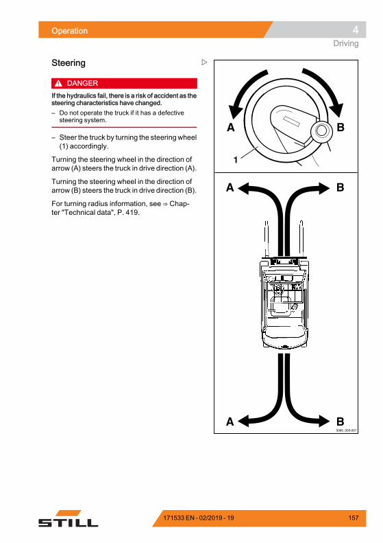
Operation 4Driving
A
A B
A B
B
5060_003-007
1
Steering
DANGERIf the hydraulics fail, there is a risk of accident as thesteering characteristics have changed.– Do not operate the truck if it has a defective
steering system.
– Steer the truck by turning the steeringwheel(1) accordingly.
Turning the steering wheel in the direction ofarrow (A) steers the truck in drive direction (A).
Turning the steering wheel in the direction ofarrow (B) steers the truck in drive direction (B).
For turning radius information, see ⇒ Chap-ter "Technical data", P. 419.
171533 EN - 02/2019 - 19 157
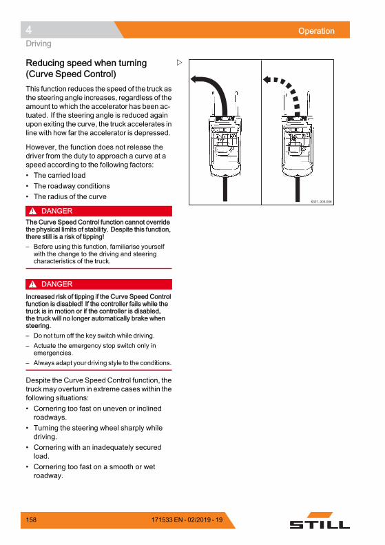
4 OperationDriving
6327_003-006
Reducing speed when turning(Curve Speed Control)This function reduces the speed of the truck asthe steering angle increases, regardless of theamount to which the accelerator has been ac-tuated. If the steering angle is reduced againupon exiting the curve, the truck accelerates inline with how far the accelerator is depressed.
However, the function does not release thedriver from the duty to approach a curve at aspeed according to the following factors:• The carried load• The roadway conditions• The radius of the curve
DANGERThe Curve Speed Control function cannot overridethe physical limits of stability. Despite this function,there still is a risk of tipping!– Before using this function, familiarise yourself
with the change to the driving and steeringcharacteristics of the truck.
DANGERIncreased risk of tipping if the Curve Speed Controlfunction is disabled! If the controller fails while thetruck is in motion or if the controller is disabled,the truck will no longer automatically brake whensteering.– Do not turn off the key switch while driving.– Actuate the emergency stop switch only in
emergencies.– Always adapt your driving style to the conditions.
Despite the Curve Speed Control function, thetruckmay overturn in extreme caseswithin thefollowing situations:• Cornering too fast on uneven or inclinedroadways.
• Turning the steering wheel sharply whiledriving.
• Cornering with an inadequately securedload.
• Cornering too fast on a smooth or wetroadway.
158 171533 EN - 02/2019 - 19
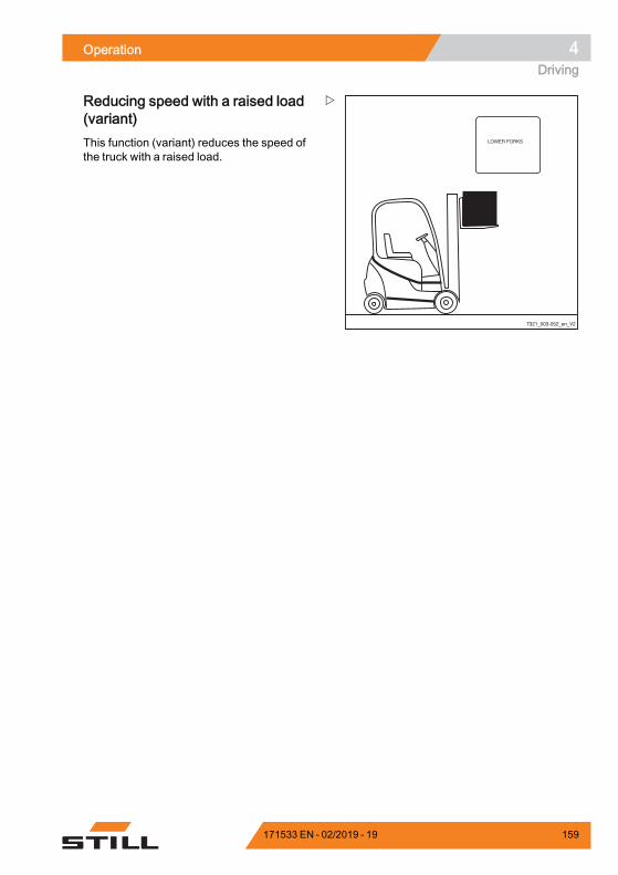
Operation 4Driving
7321_003-052_en_V2
Reducing speed with a raised load(variant)This function (variant) reduces the speed ofthe truck with a raised load.
171533 EN - 02/2019 - 19 159
4 OperationParking
ParkingParking the truck securely andswitching it off
DANGERThere is a risk of fatal injury from beingrun over if the truck rolls away.– The truck must not be parked on a
slope.– In emergencies, secure with
wedges on the side facing downhill.– Do not leave the truck until the
parking brake has been applied.
DANGERThere is a risk to life caused by a falling load or iftruck components are being lowered.– Lower the load fully before leaving the truck.
CAUTIONBatteries may freeze!If the truck is parked in an ambient temperature ofbelow -10°C for an extended period, the batterieswill cool down. The electrolyte may freeze anddamage the batteries. The truck is then not readyfor operation.– At ambient temperatures of below -10°C, only
park the truck for short periods of time.
– Apply parking brake.
160 171533 EN - 02/2019 - 19
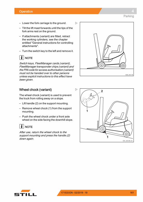
Operation 4Parking
5060_003-130
– Lower the fork carriage to the ground.
– Tilt the lift mast forwards until the tips of thefork arms rest on the ground.
– If attachments (variant) are fitted, retractthe working cylinders; see the chapterentitled "General instructions for controllingattachments".
– Turn the switch key to the left and remove it.
NOTE
Switch keys, FleetManager cards (variant),FleetManager transponder chips (variant) andthe PIN code for access authorisation (variant)must not be handed over to other personsunless explicit instructions to this effect havebeen given.
7321_003-039_V2
2
1
1
Wheel chock (variant)The wheel chock (variant) is used to preventthe truck from rolling away on a slope.
– Lift handle (2) on the support mounting.
– Remove wheel chock (1) from the supportmounting.
– Push the wheel chock under a front axlewheel on the side facing the downhill slope.
NOTE
After use, return the wheel chock to thesupport mounting and press the handle (2)down again.
171533 EN - 02/2019 - 19 161
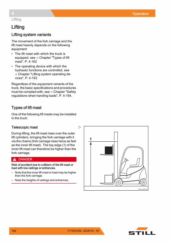
4 OperationLifting
LiftingLifting system variantsThe movement of the fork carriage and thelift mast heavily depends on the followingequipment:• The lift mast with which the truck isequipped, see ⇒ Chapter "Types of liftmast", P. 4-162
• The operating device with which thehydraulic functions are controlled, see⇒ Chapter "Lifting system operating de-vices", P. 4-163
Regardless of the equipment variants of thetruck, the basic specifications and proceduresmust be complied with, see ⇒ Chapter "Safetyregulations when handing loads", P. 4-184.
Types of lift mastOne of the following lift masts may be installedin the truck:
6210_810-001
1
Telescopic mastDuring lifting, the lift mast rises over the outerlift cylinders, bringing the fork carriage with itvia the chains (fork carriage rises twice as fastas the inner lift mast). The top edge (1) of theinner lift mast can therefore be higher than thefork carriage.
DANGERRisk of accident due to collision of the lift mast orload with low ceilings or entrances.– Note that the inner lift mast or loadmay be higher
than the fork carriage.– Note the heights of ceilings and entrances.
162 171533 EN - 02/2019 - 19
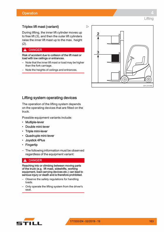
Operation 4Lifting
6210_810-002
2
3
Triplex lift mast (variant)During lifting, the inner lift cylinder moves upto free lift (3), and then the outer lift cylindersraise the inner lift mast up to the max. height(2).
DANGERRisk of accident due to collision of the lift mast orload with low ceilings or entrances.– Note that the inner lift mast or loadmay be higher
than the fork carriage.– Note the heights of ceilings and entrances.
Lifting system operating devicesThe operation of the lifting system dependson the operating devices that are fitted on thetruck.
Possible equipment variants include:• Multiple-lever• Double mini-lever• Triple mini-lever• Quadruple mini-lever• Joystick 4Plus• Fingertip
– The following informationmust be observedregardless of the equipment variant:
DANGERReaching into or climbing between moving partsof the truck (e.g. lift mast, sideshifts, workingequipment, load carrying devices etc.) can lead toserious injury or death and is therefore prohibited.– Observe the safety regulations for handling
loads.– Only operate the lifting system from the driver's
seat.
171533 EN - 02/2019 - 19 163
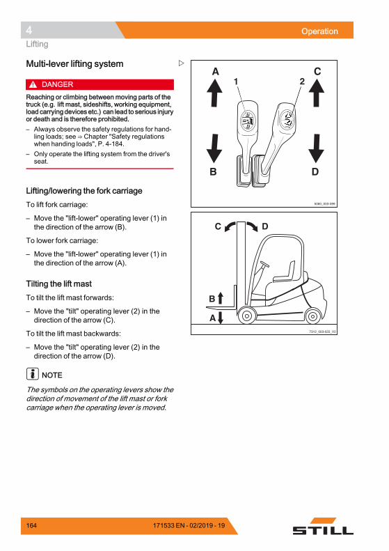
4 OperationLifting
5060_003-099
1 2A
B
C
D
7312_003-022_V2
DC
B
A
Multi-lever lifting system
DANGERReaching or climbing between moving parts of thetruck (e.g. lift mast, sideshifts, working equipment,load carryingdevices etc.) can lead to serious injuryor death and is therefore prohibited.– Always observe the safety regulations for hand-
ling loads; see ⇒ Chapter "Safety regulationswhen handing loads", P. 4-184.
– Only operate the lifting system from the driver'sseat.
Lifting/lowering the fork carriageTo lift fork carriage:
– Move the "lift-lower" operating lever (1) inthe direction of the arrow (B).
To lower fork carriage:
– Move the "lift-lower" operating lever (1) inthe direction of the arrow (A).
Tilting the lift mastTo tilt the lift mast forwards:
– Move the "tilt" operating lever (2) in thedirection of the arrow (C).
To tilt the lift mast backwards:
– Move the "tilt" operating lever (2) in thedirection of the arrow (D).
NOTE
The symbols on the operating levers show thedirection of movement of the lift mast or forkcarriage when the operating lever is moved.
164 171533 EN - 02/2019 - 19
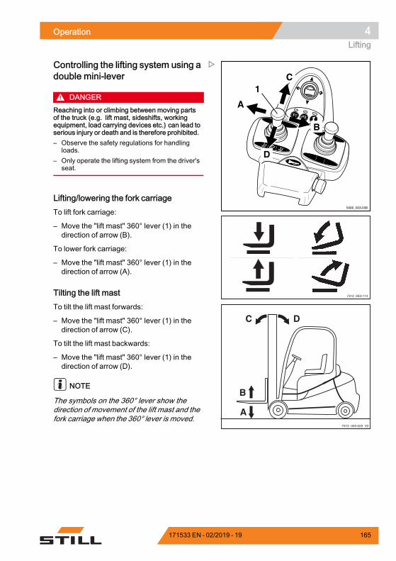
Operation 4Lifting
F1 F2
5060_003-038
A
C
D
B
1
7312_003-114
7312_003-022_V2
DC
B
A
Controlling the lifting system using adouble mini-lever
DANGERReaching into or climbing between moving partsof the truck (e.g. lift mast, sideshifts, workingequipment, load carrying devices etc.) can lead toserious injury or death and is therefore prohibited.– Observe the safety regulations for handling
loads.– Only operate the lifting system from the driver's
seat.
Lifting/lowering the fork carriageTo lift fork carriage:
– Move the "lift mast" 360° lever (1) in thedirection of arrow (B).
To lower fork carriage:
– Move the "lift mast" 360° lever (1) in thedirection of arrow (A).
Tilting the lift mastTo tilt the lift mast forwards:
– Move the "lift mast" 360° lever (1) in thedirection of arrow (C).
To tilt the lift mast backwards:
– Move the "lift mast" 360° lever (1) in thedirection of arrow (D).
NOTE
The symbols on the 360° lever show thedirection of movement of the lift mast and thefork carriage when the 360° lever is moved.
171533 EN - 02/2019 - 19 165
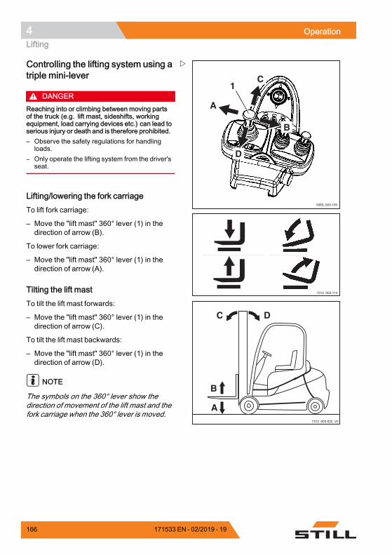
4 OperationLifting
5060_003-105
A
C
D
B
1
7312_003-114
7312_003-022_V2
DC
B
A
Controlling the lifting system using atriple mini-lever
DANGERReaching into or climbing between moving partsof the truck (e.g. lift mast, sideshifts, workingequipment, load carrying devices etc.) can lead toserious injury or death and is therefore prohibited.– Observe the safety regulations for handling
loads.– Only operate the lifting system from the driver's
seat.
Lifting/lowering the fork carriageTo lift fork carriage:
– Move the "lift mast" 360° lever (1) in thedirection of arrow (B).
To lower fork carriage:
– Move the "lift mast" 360° lever (1) in thedirection of arrow (A).
Tilting the lift mastTo tilt the lift mast forwards:
– Move the "lift mast" 360° lever (1) in thedirection of arrow (C).
To tilt the lift mast backwards:
– Move the "lift mast" 360° lever (1) in thedirection of arrow (D).
NOTE
The symbols on the 360° lever show thedirection of movement of the lift mast and thefork carriage when the 360° lever is moved.
166 171533 EN - 02/2019 - 19
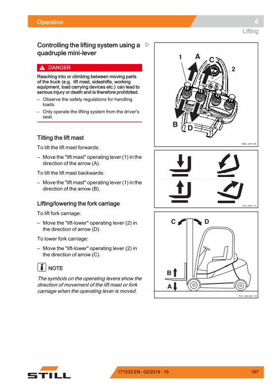
Operation 4Lifting
5060_003-106
1 C
D
2
A
B
7312_003-114
7312_003-022_V2
DC
B
A
Controlling the lifting system using aquadruple mini-lever
DANGERReaching into or climbing between moving partsof the truck (e.g. lift mast, sideshifts, workingequipment, load carrying devices etc.) can lead toserious injury or death and is therefore prohibited.– Observe the safety regulations for handling
loads.– Only operate the lifting system from the driver's
seat.
Tilting the lift mastTo tilt the lift mast forwards:
– Move the "lift mast" operating lever (1) in thedirection of the arrow (A).
To tilt the lift mast backwards:
– Move the "lift mast" operating lever (1) in thedirection of the arrow (B).
Lifting/lowering the fork carriageTo lift fork carriage:
– Move the "lift-lower" operating lever (2) inthe direction of arrow (D).
To lower fork carriage:
– Move the "lift-lower" operating lever (2) inthe direction of arrow (C).
NOTE
The symbols on the operating levers show thedirection of movement of the lift mast or forkcarriage when the operating lever is moved.
171533 EN - 02/2019 - 19 167
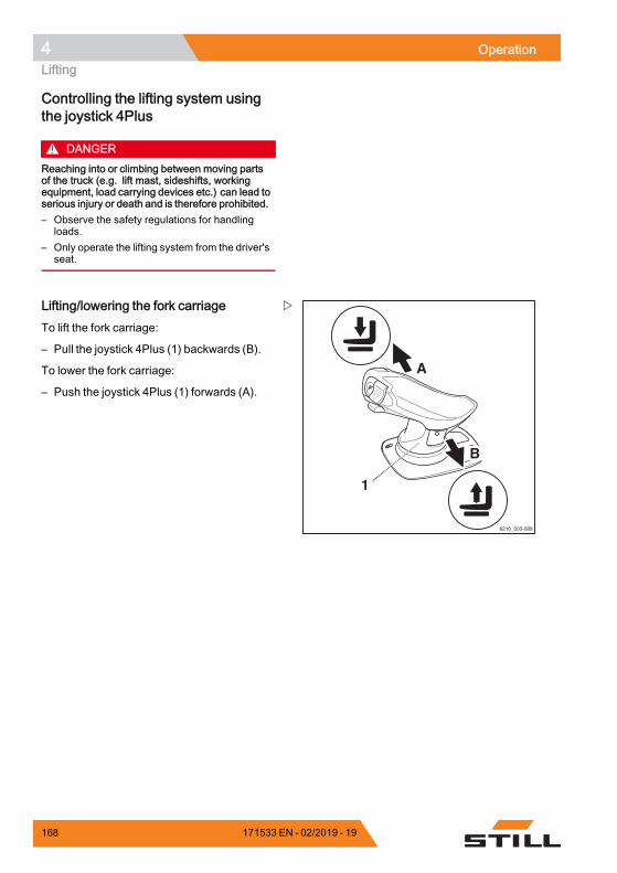
4 OperationLifting
Controlling the lifting system usingthe joystick 4Plus
DANGERReaching into or climbing between moving partsof the truck (e.g. lift mast, sideshifts, workingequipment, load carrying devices etc.) can lead toserious injury or death and is therefore prohibited.– Observe the safety regulations for handling
loads.– Only operate the lifting system from the driver's
seat.
6210_003-089
1
A
B
Lifting/lowering the fork carriageTo lift the fork carriage:
– Pull the joystick 4Plus (1) backwards (B).
To lower the fork carriage:
– Push the joystick 4Plus (1) forwards (A).
168 171533 EN - 02/2019 - 19
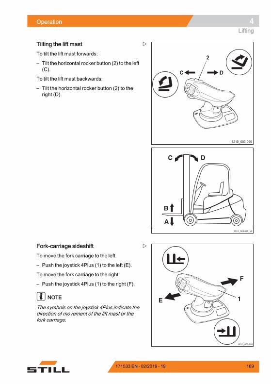
Operation 4Lifting
6210_003-090
DC
2
7312_003-022_V2
DC
B
A
Tilting the lift mastTo tilt the lift mast forwards:
– Tilt the horizontal rocker button (2) to the left(C).
To tilt the lift mast backwards:
– Tilt the horizontal rocker button (2) to theright (D).
1
6210_003-091
E
F
Fork-carriage sideshiftTo move the fork carriage to the left.
– Push the joystick 4Plus (1) to the left (E).
To move the fork carriage to the right:
– Push the joystick 4Plus (1) to the right (F).
NOTE
The symbols on the joystick 4Plus indicate thedirection of movement of the lift mast or thefork carriage.
171533 EN - 02/2019 - 19 169
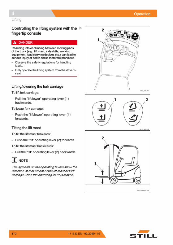
4 OperationLifting
F1F1 F2F2
6321_003-011
1
2
1 2
6210_003-043
6210_713-002_V2
2
1
Controlling the lifting system with thefingertip console
DANGERReaching into or climbing between moving partsof the truck (e.g. lift mast, sideshifts, workingequipment, load carrying devices etc.) can lead toserious injury or death and is therefore prohibited.– Observe the safety regulations for handling
loads.– Only operate the lifting system from the driver's
seat.
Lifting/lowering the fork carriageTo lift fork carriage:
– Pull the "lift/lower" operating lever (1)backwards.
To lower fork carriage:
– Push the "lift/lower" operating lever (1)forwards.
Tilting the lift mastTo tilt the lift mast forwards:
– Push the "tilt" operating lever (2) forwards.
To tilt the lift mast backwards:
– Pull the "tilt" operating lever (2) backwards.
NOTE
The symbols on the operating levers show thedirection of movement of the lift mast or forkcarriage when the operating lever is moved.
170 171533 EN - 02/2019 - 19
Operation 4Lifting
Changing the fork arms
DANGERRisk of fatal injury from being run over if the truckrolls away!– Do not park the truck on a gradient.– Apply the parking brake.– Change the fork arms in a separate, safe location
on a level surface.
WARNINGThere is a risk of injury when changing the forkarms; the weight of the fork arms could cause themto fall on your legs, feet or knees. The space to theleft and right of the fork is a danger area.– Always wear protective gloves and safety
footwear when changing the fork arms.– Ensure that no one stands in the danger area!– Do not pull on the fork arms.– The fork arms must always be carried by two
people; if necessary, use a hoist.
NOTE
• For installation and removal, a transportpallet is recommended for supportingthe fork arms. The pallet size dependson the fork arm size used and should bedimensioned such that the fork arms do notprotrude after being placed on the pallet.This means the fork arms can be safelyplaced down and transported.
• Both fork arms can be pushed over to thesame side. It is possible to choose the sidevia which the forks are removed
171533 EN - 02/2019 - 19 171
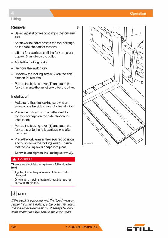
4 OperationLifting
1
2
6210_003-027
Removal– Select a pallet corresponding to the fork armsize.
– Set down the pallet next to the fork carriageon the side chosen for removal.
– Lift the fork carriage until the fork arms areapprox. 3 cm above the pallet.
– Apply the parking brake.
– Remove the switch key.
– Unscrew the locking screw (2) on the sidechosen for removal.
– Pull up the locking lever (1) and push thefork arms onto the pallet one after the other.
Installation– Make sure that the locking screw is un-screwed on the side chosen for installation.
– Place the fork arms on a pallet next tothe fork carriage on the side chosen forinstallation.
– Pull up the locking lever (1) and push thefork arms onto the fork carriage one afterthe other.
– Place the fork arms in the required positionand push down the locking lever. Ensurethat the locking lever snaps into place.
– Screw in and tighten the locking screw (2).
DANGERThere is a risk of fatal injury from a falling load orfork!– Tighten the locking screw each time a fork is
changed.– Driving and moving loads without the locking
screw is prohibited.
NOTE
If the truck is equipped with the "load measu-rement" comfort feature, a "zero adjustment ofthe load measurement" must always be per-formed after the fork arms have been chan-
172 171533 EN - 02/2019 - 19
Operation 4Lifting
ged. Otherwise, correct load measurementcannot be guaranteed.
Fork extension (variant)
DANGERThere is a risk of being run over if the truck rollsaway and therefore a danger to life.– Do not park the truck on a slope.– Apply the parking brake.– Change the fork extension in a separate, safe
location on a level surface.
WARNINGThere is a risk of crushing!Theweight of the fork extension can cause crushingor cuts on sharp edges or burrs.– Always wear protective gloves and safety
footwear.
WARNINGThere is a risk of tipping!The weight and dimensions of the fork extensionaffect the stability of the truck. The permissibleweights stated on the capacity rating plate must bereduced in proportion to the actual load distance.The truck is equipped with a fork extension exworks, the capacity rating plate is already adjustedaccordingly.– Observe load capacity, see the "Before picking
up a load" chapter.
NOTE
If the truck is equipped with the "load measu-rement" comfort feature, a "zero adjustment ofthe load measurement" must always be per-formed after the fork extensions have beenchanged. Otherwise, correct load measure-ment cannot be guaranteed.
171533 EN - 02/2019 - 19 173
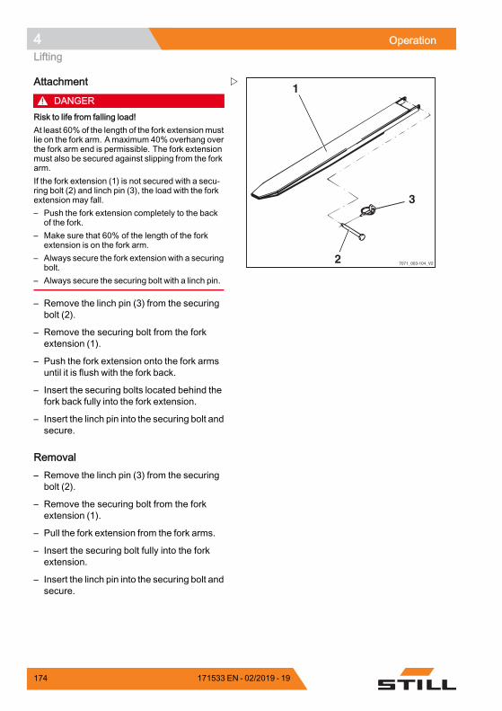
4 OperationLifting
7071_003-104_V2
1
2
3
Attachment
DANGERRisk to life from falling load!At least 60% of the length of the fork extensionmustlie on the fork arm. Amaximum 40% overhang overthe fork arm end is permissible. The fork extensionmust also be secured against slipping from the forkarm.If the fork extension (1) is not secured with a secu-ring bolt (2) and linch pin (3), the load with the forkextension may fall.– Push the fork extension completely to the back
of the fork.– Make sure that 60% of the length of the fork
extension is on the fork arm.– Always secure the fork extension with a securing
bolt.– Always secure the securing bolt with a linch pin.
– Remove the linch pin (3) from the securingbolt (2).
– Remove the securing bolt from the forkextension (1).
– Push the fork extension onto the fork armsuntil it is flush with the fork back.
– Insert the securing bolts located behind thefork back fully into the fork extension.
– Insert the linch pin into the securing bolt andsecure.
Removal– Remove the linch pin (3) from the securingbolt (2).
– Remove the securing bolt from the forkextension (1).
– Pull the fork extension from the fork arms.
– Insert the securing bolt fully into the forkextension.
– Insert the linch pin into the securing bolt andsecure.
174 171533 EN - 02/2019 - 19
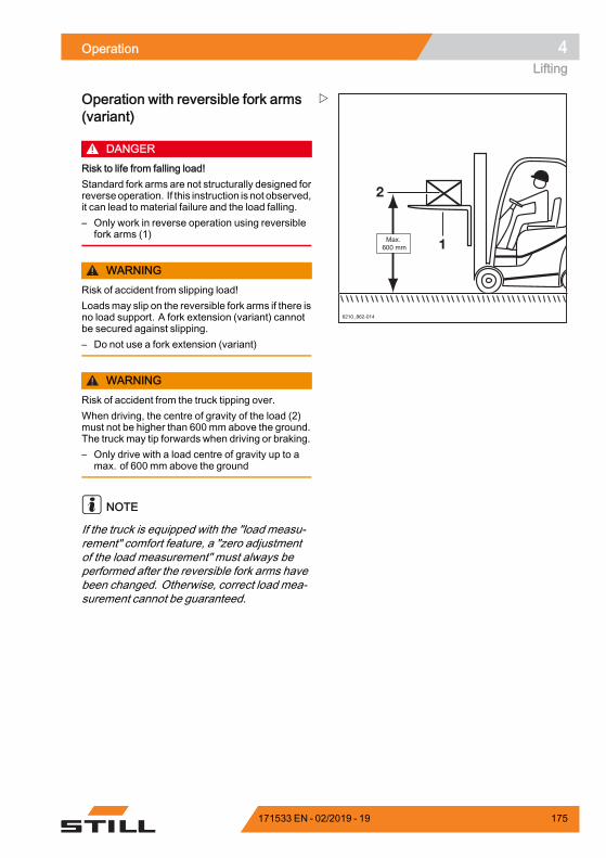
Operation 4Lifting
Operation with reversible fork arms(variant)
DANGERRisk to life from falling load!Standard fork arms are not structurally designed forreverseoperation. If this instruction is not observed,it can lead to material failure and the load falling.– Only work in reverse operation using reversible
fork arms (1)
WARNINGRisk of accident from slipping load!Loadsmay slip on the reversible fork arms if there isno load support. A fork extension (variant) cannotbe secured against slipping.– Do not use a fork extension (variant)
WARNINGRisk of accident from the truck tipping over.When driving, the centre of gravity of the load (2)must not be higher than 600 mm above the ground.The truck may tip forwards when driving or braking.– Only drive with a load centre of gravity up to a
max. of 600 mm above the ground
NOTE
If the truck is equipped with the "load measu-rement" comfort feature, a "zero adjustmentof the load measurement" must always beperformed after the reversible fork arms havebeen changed. Otherwise, correct load mea-surement cannot be guaranteed.
171533 EN - 02/2019 - 19 175
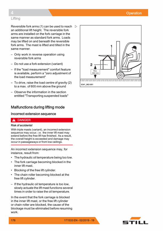
4 OperationLifting
6341_862-001
Reversible fork arms (1) can be used to reachan additional lift height. The reversible forkarms are installed on the fork carriage in thesame manner as standard fork arms. Loadsmay be lifted on and beneath the reversiblefork arms. The mast is lifted and tilted in thesamemanner.
– Only work in reverse operation usingreversible fork arms
– Do not use a fork extension (variant)
– If the "load measurement" comfort featureis available, perform a "zero adjustment ofthe load measurement"
– To drive, raise the load centre of gravity (2)to a max. of 600 mm above the ground
– Observe the information in the sectionentitled "Transporting suspended loads"
Malfunctions during lifting mode
Incorrect extension sequence
DANGERRisk of accidents!With triple masts (variant), an incorrect extensionsequence may occur, i.e. the inner lift mast mayextend before the free lift has finished. As a result,the overall height is exceeded and damage mayoccur in passageways or from low ceilings.
An incorrect extension sequence may, forinstance, result from:• The hydraulic oil temperature being too low.• The fork carriage becoming blocked in theinner lift mast.
• Blocking of the free lift cylinder.• The chain roller becoming blocked at thefree lift cylinder.
– If the hydraulic oil temperature is too low,slowly actuate the lift mast functions severaltimes in order to raise the oil temperature.
In the event that the fork carriage is blockedin the inner lift mast, or the free lift cylinderor chain roller are blocked, the cause of theblockage must be eliminated before resumingwork.
176 171533 EN - 02/2019 - 19
Operation 4Lifting
– Notify your service centre
Load chains not under tension
DANGERDanger caused by a falling load!– Make sure that the chain(s) does (do) not
become slack when lowering the load.
Slack chains can, for instance, result from:• Resting the fork carriage or the load on theracking.
• Fork carriage rollers becoming blocked inthe lift mast due to contamination.
– If the fork carriage or the load comes to anunexpected stop, lift the fork carriage untilthe chains are under tension again andlower the load at another suitable location.
– If the fork carriage rollers in the lift mastbecome blocked due to contamination, liftthe fork carriage until the chains are undertension again. Remove the contaminationbefore resuming work.
WARNINGRisk of injury!– Observe the safety regulations for working on lift
masts; see⇒Chapter "Working at the front of thetruck", P. 5-374.
Hydraulic blocking functionThe hydraulic blocking function ensures thatall the functions of the working hydraulicsare disabled whenever the seat switch in thedriver's seat is unloaded.
If the driver stands up from the driver's seat,the blocking function prevents the hydraulicfunctions that:• Lift the load• Lower the load• Tilt the lift mast• Additional functions
171533 EN - 02/2019 - 19 177
4 OperationLifting
Releasing the block on the hydraulicsProceed as follows to release the block on thehydraulics:
– Sit down on the driver's seat.
All the relevant functions of the workinghydraulics will be available again.
NOTE
If it is not possible to release the block on thehydraulics when the load is raised becauseof a technical fault, the load must be loweredusing the "emergency lowering" mechanismbefore any further action is taken. Do notoperate the truck again until the fault has beenrectified by the authorised service centre.
Automatic lift cut out (variant)
Description:The automatic lift cut out (variant) means thatthe load cannot be lifted above a preset height.This function uses a sensor that is welded onat the factory at the required lift mast limitheight. Once attached, the height cannot beeasily changed.
Application:• If the ceiling of the building is lower thanthe maximum lift height of the truck, thisvariant can prevent the lift mast fromaccidentally hitting the ceiling, which canresult in damage.
• If the truck is frequently used at a particularheight, the work is simplified by the auto-matic lift cut out at this height.
NOTE
If a load is lifted very quickly, the fork carriageand load are moved approximately 15 cmabove the position of the sensor due toinertia. This deviation is already taken intoconsideration at the factory when determiningthe position of the sensor.
178 171533 EN - 02/2019 - 19
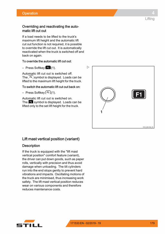
Operation 4Lifting
Overriding and reactivating the auto-matic lift cut outIf a load needs to be lifted to the truck'smaximum lift height and the automatic liftcut out function is not required, it is possibleto override the lift cut out. It is automaticallyreactivated when the truck is switched off andback on again.
To override the automatic lift cut out:
F1
1
7312_003-160_V3
– Press Softkey (1).
Automatic lift cut out is switched off.The symbol is displayed. Loads can belifted to the maximum lift height for the truck.
To switch the automatic lift cut out back on:
– Press Softkey (1).
Automatic lift cut out is switched on.The symbol is displayed. Loads can belifted only to the set lift height for the truck.
Lift mast vertical position (variant)
DescriptionIf the truck is equipped with the "lift mastvertical position" comfort feature (variant),the driver can put down goods, such as paperrolls, vertically with precision and thus avoiddamage when unloading. The tilt cylindersrun into the end stops gently to prevent hardvibrations and impacts. Oscillating motions ofthe truck are minimised, thus increasing worksafety. The lift mast vertical position reduceswear on various components and thereforereduces maintenance costs.
171533 EN - 02/2019 - 19 179
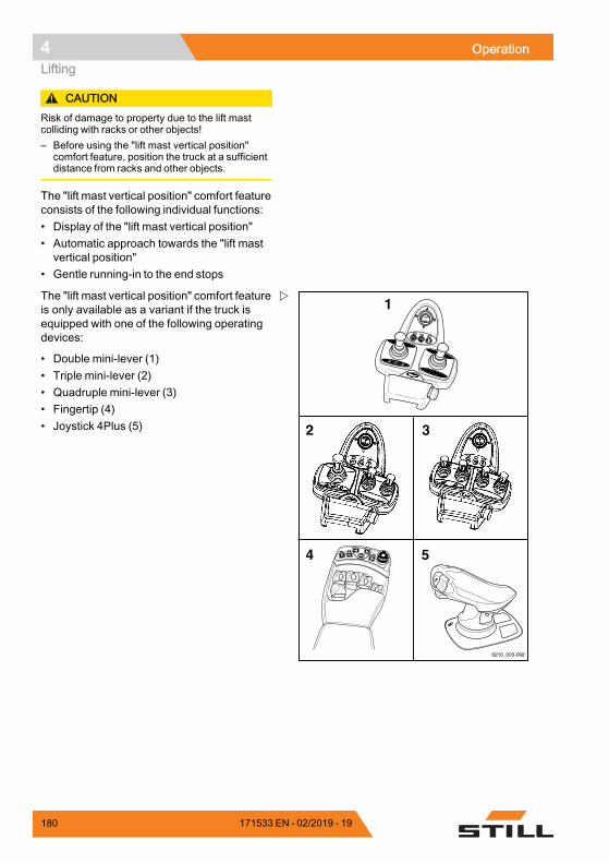
4 OperationLifting
CAUTIONRisk of damage to property due to the lift mastcolliding with racks or other objects!– Before using the "lift mast vertical position"
comfort feature, position the truck at a sufficientdistance from racks and other objects.
The "lift mast vertical position" comfort featureconsists of the following individual functions:• Display of the "lift mast vertical position"• Automatic approach towards the "lift mastvertical position"
• Gentle running-in to the end stops
F1F1 F2F2
F1 F2
6210_003-092
1
2
4 5
3
The "lift mast vertical position" comfort featureis only available as a variant if the truck isequipped with one of the following operatingdevices:
• Double mini-lever (1)• Triple mini-lever (2)• Quadruple mini-lever (3)• Fingertip (4)• Joystick 4Plus (5)
180 171533 EN - 02/2019 - 19
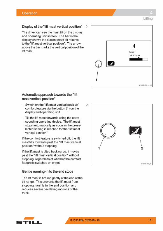
Operation 4Lifting
6210_003-069_en_V2
1
Display of the "lift mast vertical position"The driver can see the mast tilt on the displayand operating unit screen. The bar in thedisplay shows the current mast tilt relativeto the "lift mast vertical position". The arrowabove the barmarks the vertical position of thelift mast.
Automatic approach towards the "liftmast vertical position"
6210_003-067_V2
21
– Switch on the "lift mast vertical position"comfort feature via the button (1) on thedisplay and operating unit.
– Tilt the lift mast forwards using the corre-sponding operating device. The lift maststops automatically as soon as the prese-lected setting is reached for the "lift mastvertical position".
If the comfort feature is switched off, the liftmast tilts forwards past the "lift mast verticalposition" without stopping.
If the lift mast is tilted backwards, it movespast the "lift mast vertical position" withoutstopping, regardless of whether the comfortfeature is switched on or not.
Gentle running-in to the end stops
The lift mast is braked gently at the end of thetilt range. This prevents the lift mast fromstopping harshly in the end position andreduces severe oscillating motions of thetruck.
171533 EN - 02/2019 - 19 181
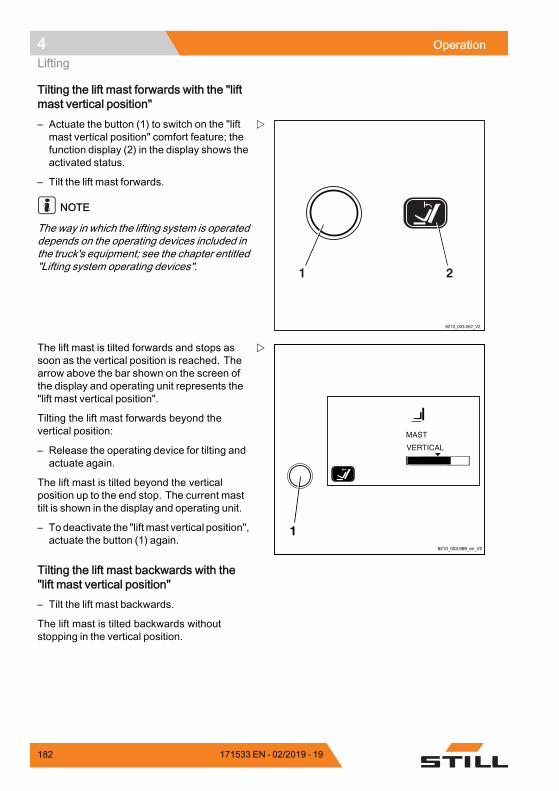
4 OperationLifting
Tilting the lift mast forwards with the "liftmast vertical position"
6210_003-067_V2
21
– Actuate the button (1) to switch on the "liftmast vertical position" comfort feature; thefunction display (2) in the display shows theactivated status.
– Tilt the lift mast forwards.
NOTE
The way in which the lifting system is operateddepends on the operating devices included inthe truck's equipment; see the chapter entitled"Lifting system operating devices".
6210_003-069_en_V2
1
The lift mast is tilted forwards and stops assoon as the vertical position is reached. Thearrow above the bar shown on the screen ofthe display and operating unit represents the"lift mast vertical position".
Tilting the lift mast forwards beyond thevertical position:
– Release the operating device for tilting andactuate again.
The lift mast is tilted beyond the verticalposition up to the end stop. The current masttilt is shown in the display and operating unit.
– To deactivate the "liftmast vertical position",actuate the button (1) again.
Tilting the lift mast backwards with the"lift mast vertical position"– Tilt the lift mast backwards.
The lift mast is tilted backwards withoutstopping in the vertical position.
182 171533 EN - 02/2019 - 19
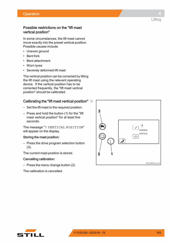
Operation 4Lifting
Possible restrictions on the "lift mastvertical position"
In some circumstances, the lift mast cannotmove exactly into the preset vertical position.Possible causes include:• Uneven ground• Bent fork• Bent attachment• Worn tyres• Severely deformed lift mast
The vertical position can be corrected by tiltingthe lift mast using the relevant operatingdevice. If the vertical position has to becorrected frequently, the "lift mast verticalposition" should be calibrated.
6210_003-070_en_V2
12
3
Calibrating the "lift mast vertical position"– Set the lift mast to the required position.
– Press and hold the button (1) for the "liftmast vertical position" for at least fiveseconds.
The message "? VERTICAL POSITION"will appear on the display.
Storing the mast position:
– Press the drive program selection button(3).
The current mast position is stored.
Cancelling calibration:
– Press the menu change button (2).
The calibration is cancelled.
171533 EN - 02/2019 - 19 183
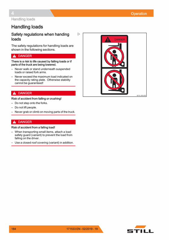
4 OperationHandling loads
Handling loads
6210_003-030
Safety regulations when handingloadsThe safety regulations for handling loads areshown in the following sections.
DANGERThere is a risk to life caused by falling loads or ifparts of the truck are being lowered.– Never walk or stand underneath suspended
loads or raised fork arms.– Never exceed the maximum load indicated on
the capacity rating plate. Otherwise stabilitycannot be guaranteed!
DANGERRisk of accident from falling or crushing!– Do not step onto the forks.– Do not lift people.– Never grab or climb on moving parts of the truck.
DANGERRisk of accident from a falling load!– When transporting small items, attach a load
safety guard (variant) to prevent the load fromfalling on the driver.
– Use a closed roof covering (variant) in addition.
184 171533 EN - 02/2019 - 19
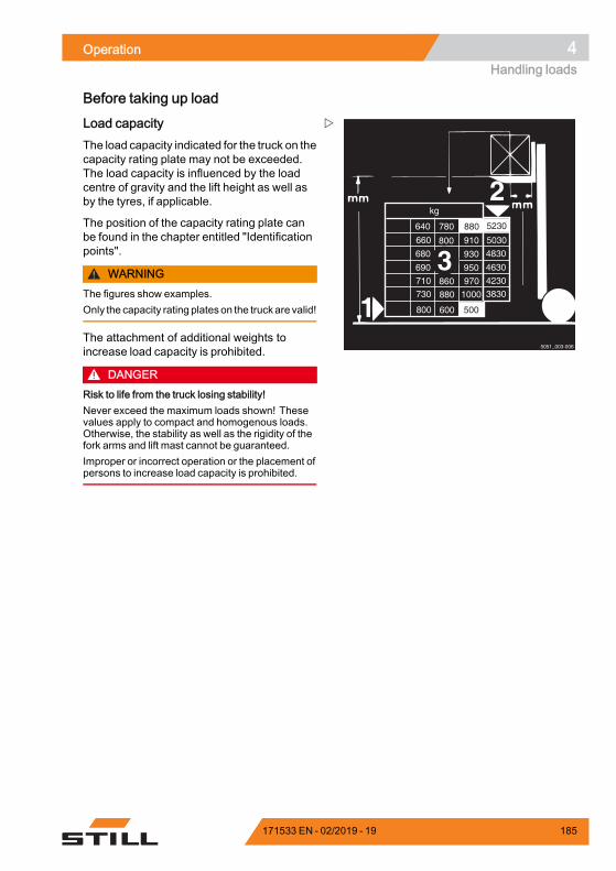
Operation 4Handling loads
Before taking up load
2
1
780
9101310
93012306801500
95012606901500
970860710150010008807301500
600500
6401080
4830
4630
4230
3830
kg
3
5051_003-006
800
800 5030660
5230
500
880
Load capacityThe load capacity indicated for the truck on thecapacity rating plate may not be exceeded.The load capacity is influenced by the loadcentre of gravity and the lift height as well asby the tyres, if applicable.
The position of the capacity rating plate canbe found in the chapter entitled "Identificationpoints".
WARNINGThe figures show examples.Only the capacity rating plateson the truckare valid!
The attachment of additional weights toincrease load capacity is prohibited.
DANGERRisk to life from the truck losing stability!Never exceed the maximum loads shown! Thesevalues apply to compact and homogenous loads.Otherwise, the stability as well as the rigidity of thefork arms and lift mast cannot be guaranteed.Improper or incorrect operation or the placement ofpersons to increase load capacity is prohibited.
171533 EN - 02/2019 - 19 185
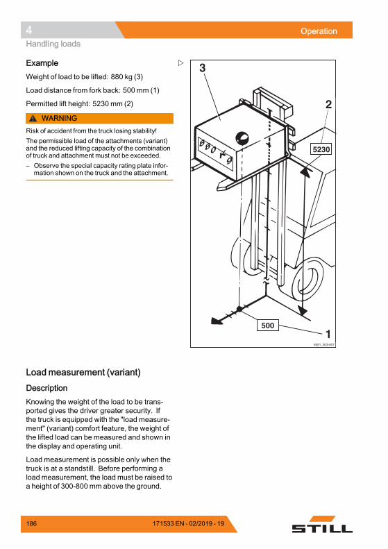
4 OperationHandling loads
5051_003-007
3
5230
500
2
880 Kg
1
ExampleWeight of load to be lifted: 880 kg (3)
Load distance from fork back: 500 mm (1)
Permitted lift height: 5230 mm (2)
WARNINGRisk of accident from the truck losing stability!The permissible load of the attachments (variant)and the reduced lifting capacity of the combinationof truck and attachment must not be exceeded.– Observe the special capacity rating plate infor-
mation shown on the truck and the attachment.
Load measurement (variant)
DescriptionKnowing the weight of the load to be trans-ported gives the driver greater security. Ifthe truck is equipped with the "load measure-ment" (variant) comfort feature, the weight ofthe lifted load can be measured and shown inthe display and operating unit.
Load measurement is possible only when thetruck is at a standstill. Before performing aload measurement, the load must be raised toa height of 300-800 mm above the ground.
186 171533 EN - 02/2019 - 19
Operation 4Handling loads
The load measurement has an accuracy of+/-3% of the rated capacity of the truck.
NOTE
In order to ensure accuracy at all times, a zeroadjustment of the load measurement must becarried out. Zero adjustment is required.• as part of daily commissioning• after changing the fork arms• after fitting or changing attachments.
Performing the load measurement
DANGERRisk of accident from a falling load!The loadmay fall if the load centre of gravity has notbeen taken into account or the load has not beenpicked up securely.– Pick up the load securely; see the chapter
entitled "Picking up loads".
CAUTIONIf the weight determined by a load measurementexceeds the permissible residual load capacity ofthe truck, the truck cannot be operated safely.– Set down and reduce load immediately.– If necessary, use another truck with sufficient
load-bearing capacity.
NOTE
Accurate load measurement is only possibleunder the following conditions:• The hydraulic oil is at normal operatingtemperature
• The load is at rest at the beginning of theload measurement
• The load corresponds to at least 10% of thenominal load capacity in trucks with a loadcapacity of up to 2.5 t
• The load corresponds to at least 5% of thenominal load capacity in trucks with a loadcapacity of 3 t and over
• The lift mast is in the vertical position• The fork is not raised to more than 800 mmabove the ground
171533 EN - 02/2019 - 19 187
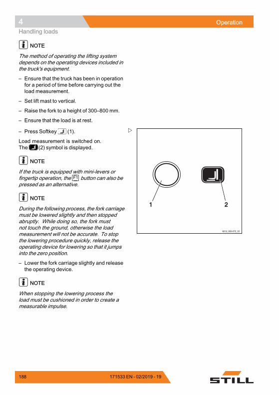
4 OperationHandling loads
NOTE
The method of operating the lifting systemdepends on the operating devices included inthe truck's equipment.
– Ensure that the truck has been in operationfor a period of time before carrying out theload measurement.
– Set lift mast to vertical.
– Raise the fork to a height of 300–800 mm.
– Ensure that the load is at rest.
6210_003-072_V2
21
– Press Softkey (1).
Load measurement is switched on.The (2) symbol is displayed.
NOTE
If the truck is equipped with mini-levers orfingertip operation, the F1 button can also bepressed as an alternative.
NOTE
During the following process, the fork carriagemust be lowered slightly and then stoppedabruptly. While doing so, the fork mustnot touch the ground, otherwise the loadmeasurement will not be accurate. To stopthe lowering procedure quickly, release theoperating device for lowering so that it jumpsinto the zero position.
– Lower the fork carriage slightly and releasethe operating device.
NOTE
When stopping the lowering process theload must be cushioned in order to create ameasurable impulse.
188 171533 EN - 02/2019 - 19
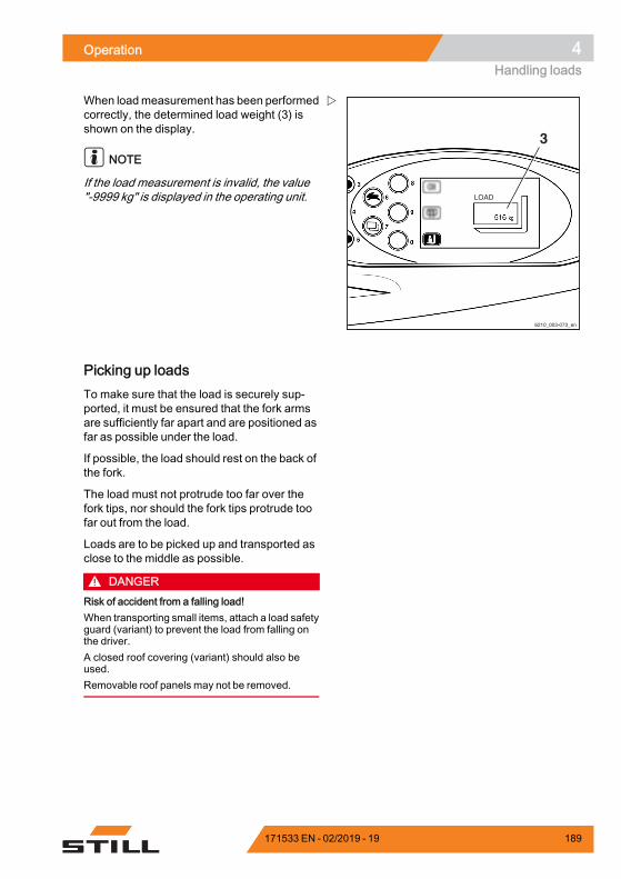
Operation 4Handling loads
6210_003-073_en
3
When loadmeasurement has been performedcorrectly, the determined load weight (3) isshown on the display.
NOTE
If the load measurement is invalid, the value"-9999 kg" is displayed in the operating unit.
Picking up loadsTo make sure that the load is securely sup-ported, it must be ensured that the fork armsare sufficiently far apart and are positioned asfar as possible under the load.
If possible, the load should rest on the back ofthe fork.
The load must not protrude too far over thefork tips, nor should the fork tips protrude toofar out from the load.
Loads are to be picked up and transported asclose to the middle as possible.
DANGERRisk of accident from a falling load!When transporting small items, attach a load safetyguard (variant) to prevent the load from falling onthe driver.A closed roof covering (variant) should also beused.Removable roof panels may not be removed.
171533 EN - 02/2019 - 19 189
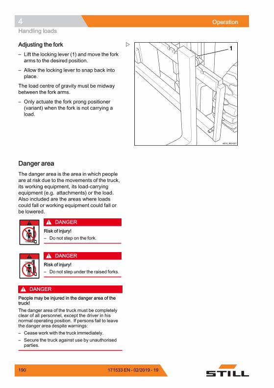
4 OperationHandling loads
1
6210_842-001
Adjusting the fork– Lift the locking lever (1) and move the forkarms to the desired position.
– Allow the locking lever to snap back intoplace.
The load centre of gravity must be midwaybetween the fork arms.
– Only actuate the fork prong positioner(variant) when the fork is not carrying aload.
Danger areaThe danger area is the area in which peopleare at risk due to the movements of the truck,its working equipment, its load-carryingequipment (e.g. attachments) or the load.Also included are the areas where loadscould fall or working equipment could fall orbe lowered.
DANGERRisk of injury!– Do not step on the fork.
DANGERRisk of injury!– Do not step under the raised forks.
DANGERPeople may be injured in the danger area of thetruck!The danger area of the truck must be completelyclear of all personnel, except the driver in hisnormal operating position. If persons fail to leavethe danger area despite warnings:– Cease work with the truck immediately.– Secure the truck against use by unauthorised
parties.
190 171533 EN - 02/2019 - 19
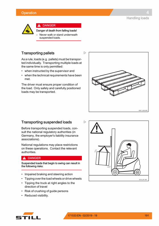
Operation 4Handling loads
DANGERDanger of death from falling loads!– Never walk or stand underneath
suspended loads.
6327_003-009
Transporting palletsAsa rule, loads (e.g. pallets)must be transpor-ted individually. Transporting multiple loads atthe same time is only permitted:• when instructed by the supervisor and• when the technical requirements have beenmet.
The driver must ensure proper condition ofthe load. Only safely and carefully positionedloads may be transported.
6210_001-007
Transporting suspended loadsBefore transporting suspended loads, con-sult the national regulatory authorities (inGermany, the employer's liability insuranceassociations).
National regulations may place restrictionson these operations. Contact the relevantauthorities.
DANGERSuspended loads that begin to swing can result inthe following risks:
• Impaired braking and steering action• Tipping over the loadwheels or drivewheels• Tipping the truck at right angles to thedirection of travel
• Risk of crushing of guide persons• Reduced visibility.
171533 EN - 02/2019 - 19 191
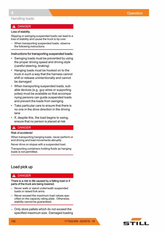
4 OperationHandling loads
DANGERLoss of stability.Slipping or swinging suspended loads can lead to aloss of stability and cause the truck to tip over.– When transporting suspended loads, observe
the following instructions
Instructions for transporting suspended loads:• Swinging loads must be prevented by usingthe proper driving speed and driving style(careful steering, braking)
• Hanging loads must be hooked on to thetruck in such a way that the harness cannotshift or release unintentionally and cannotbe damaged
• When transporting suspended loads, suit-able devices (e.g. guy wires or supportingpoles) must be available so that accompa-nying persons can guide suspended loadsand prevent the loads from swinging
• Take particular care to ensure that there isno one in the drive direction in the drivinglane
• If, despite this, the load begins to swing,ensure that no person is placed at risk
DANGERRisk of accidents!When transporting hanging loads, never perform orend driving and load movements abruptly.Never drive on slopes with a suspended load.Transporting containers holding fluids as hangingloads is not permitted.
Load pick up
DANGERThere is a risk to life caused by a falling load or ifparts of the truck are being lowered.– Never walk or stand underneath suspended
loads or raised fork arms.– Never exceed the maximum load values spe-
cified on the capacity rating plate. Otherwise,stability cannot be guaranteed.
– Only store pallets which do not exceed thespecified maximum size. Damaged loading
192 171533 EN - 02/2019 - 19
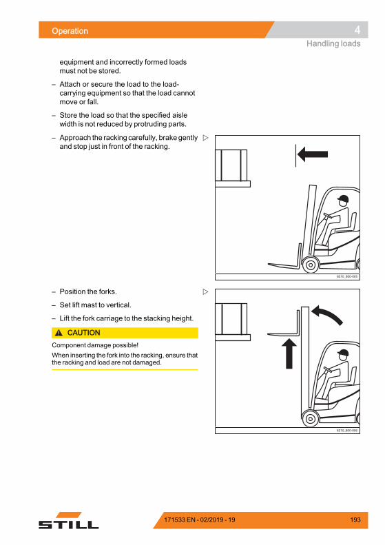
Operation 4Handling loads
equipment and incorrectly formed loadsmust not be stored.
– Attach or secure the load to the load-carrying equipment so that the load cannotmove or fall.
– Store the load so that the specified aislewidth is not reduced by protruding parts.
6210_800-005
– Approach the racking carefully, brake gentlyand stop just in front of the racking.
6210_800-006
– Position the forks.
– Set lift mast to vertical.
– Lift the fork carriage to the stacking height.
CAUTIONComponent damage possible!When inserting the fork into the racking, ensure thatthe racking and load are not damaged.
171533 EN - 02/2019 - 19 193
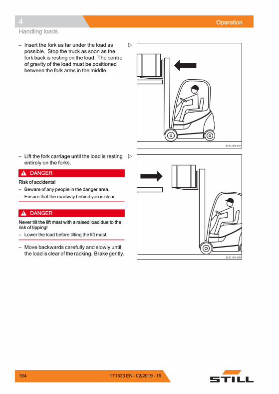
4 OperationHandling loads
6210_800-007
– Insert the fork as far under the load aspossible. Stop the truck as soon as thefork back is resting on the load. The centreof gravity of the load must be positionedbetween the fork arms in the middle.
6210_800-008
– Lift the fork carriage until the load is restingentirely on the forks.
DANGERRisk of accidents!– Beware of any people in the danger area.– Ensure that the roadway behind you is clear.
DANGERNever tilt the lift mast with a raised load due to therisk of tipping!– Lower the load before tilting the lift mast.
– Move backwards carefully and slowly untilthe load is clear of the racking. Brake gently.
194 171533 EN - 02/2019 - 19
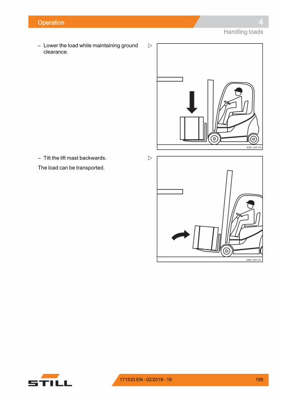
Operation 4Handling loads
5060_003-102
– Lower the load while maintaining groundclearance.
5060_003-101
– Tilt the lift mast backwards.
The load can be transported.
171533 EN - 02/2019 - 19 195
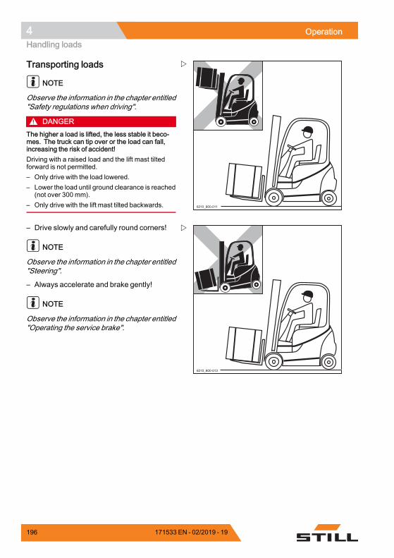
4 OperationHandling loads
6210_800-011
Transporting loads
NOTE
Observe the information in the chapter entitled"Safety regulations when driving".
DANGERThe higher a load is lifted, the less stable it beco-mes. The truck can tip over or the load can fall,increasing the risk of accident!Driving with a raised load and the lift mast tiltedforward is not permitted.– Only drive with the load lowered.– Lower the load until ground clearance is reached
(not over 300 mm).– Only drive with the lift mast tilted backwards.
6210_800-013
– Drive slowly and carefully round corners!
NOTE
Observe the information in the chapter entitled"Steering".
– Always accelerate and brake gently!
NOTE
Observe the information in the chapter entitled"Operating the service brake".
196 171533 EN - 02/2019 - 19
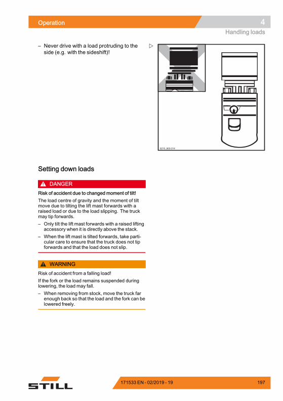
Operation 4Handling loads
6210_800-014
– Never drive with a load protruding to theside (e.g. with the sideshift)!
Setting down loads
DANGERRisk of accident due to changed moment of tilt!The load centre of gravity and the moment of tiltmove due to tilting the lift mast forwards with araised load or due to the load slipping. The truckmay tip forwards.– Only tilt the lift mast forwards with a raised lifting
accessory when it is directly above the stack.– When the lift mast is tilted forwards, take parti-
cular care to ensure that the truck does not tipforwards and that the load does not slip.
WARNINGRisk of accident from a falling load!If the fork or the load remains suspended duringlowering, the load may fall.– When removing from stock, move the truck far
enough back so that the load and the fork can belowered freely.
171533 EN - 02/2019 - 19 197
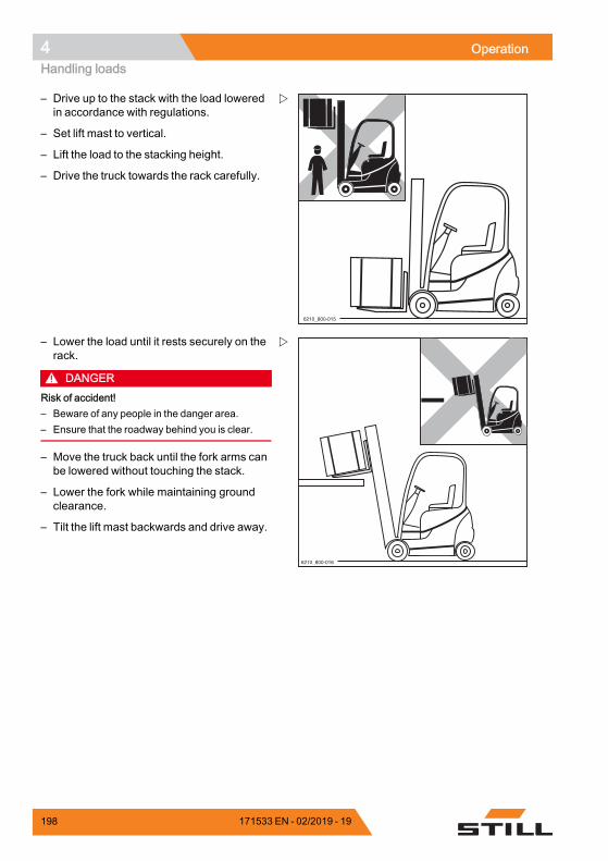
4 OperationHandling loads
6210_800-015
– Drive up to the stack with the load loweredin accordance with regulations.
– Set lift mast to vertical.
– Lift the load to the stacking height.
– Drive the truck towards the rack carefully.
6210_800-016
– Lower the load until it rests securely on therack.
DANGERRisk of accident!– Beware of any people in the danger area.– Ensure that the roadway behind you is clear.
– Move the truck back until the fork arms canbe lowered without touching the stack.
– Lower the fork while maintaining groundclearance.
– Tilt the lift mast backwards and drive away.
198 171533 EN - 02/2019 - 19
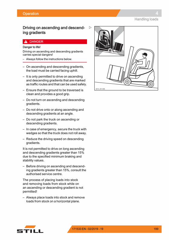
Operation 4Handling loads
6210_001-008
Driving on ascending and descend-ing gradients
DANGERDanger to life!Driving on ascending and descending gradientscarries special dangers!– Always follow the instructions below.
– On ascending and descending gradients,the load must be carried facing uphill.
– It is only permitted to drive on ascendingand descending gradients that are markedas traffic routes and that can be used safely.
– Ensure that the ground to be traversed isclean and provides a good grip.
– Do not turn on ascending and descendinggradients.
– Do not drive onto or along ascending anddescending gradients at an angle.
– Do not park the truck on ascending ordescending gradients.
– In case of emergency, secure the truck withwedges so that the truck does not roll away.
– Reduce the driving speed on descendinggradients.
It is not permitted to drive on long ascendingand descending gradients greater than 15%due to the specified minimum braking andstability values.
– Before driving on ascending and descend-ing gradients greater than 15%, consult theauthorised service centre.
The process of placing loads into stockand removing loads from stock while onan ascending or descending gradient is notpermitted!
– Always place loads into stock and removeloads from stock on a horizontal plane.
171533 EN - 02/2019 - 19 199
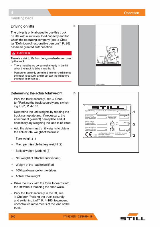
4 OperationHandling loads
5060_003-071
Driving on liftsThe driver is only allowed to use this truckon lifts with a sufficient load capacity and forwhich the operating company (see ⇒ Chap-ter "Definition of responsible persons", P. 26)has been granted authorisation.
DANGERThere is a risk to life from being crushed or run overby the truck.– There must be no personnel already in the lift
when the truck is driven into the lift.– Personnel are only permitted to enter the lift once
the truck is secure, and must exit the lift beforethe truck is driven out.
Type-Modèle-Typ / Serial no.-No. de série-Serien-Nr. / year-année-Baujahr
Rated capacityCapacité nominaleNenn-Tragfähigkeit
Battery voltageTension batterieBatteriespannung
Rated drive powerPuissance motr.nom.Nenn-Antriebsleist.
Unladen massMasse à videLeergewicht
max
min.*
kg kg
kg
kg
kgkW
V
*
* see Operating instructions voir Mode d'emploi siehe Betriebsanleitung
D-22113 HamburgBerzeliusstr. 10
1
3
2
Determining the actual total weight– Park the truck securely, see ⇒ Chap-ter "Parking the truck securely and switch-ing it off", P. 4-160.
– Determine the unit weights by reading thetruck nameplate and, if necessary, theattachment (variant) nameplate and, ifnecessary, by weighing the load to be lifted.
– Add the determined unit weights to obtainthe actual total weight of the truck:
Tare weight (1)
+ Max. permissible battery weight (2)
+ Ballast weight (variant) (3)
+ Net weight of attachment (variant)
+ Weight of the load to be lifted
+ 100 kg allowance for the driver
= Actual total weight
– Drive the truck with the forks forwards intothe lift without touching the shaft walls.
– Park the truck securely in the lift, see⇒ Chapter "Parking the truck securelyand switching it off", P. 4-160, to preventuncontrolled movements of the load or thetruck.
200 171533 EN - 02/2019 - 19
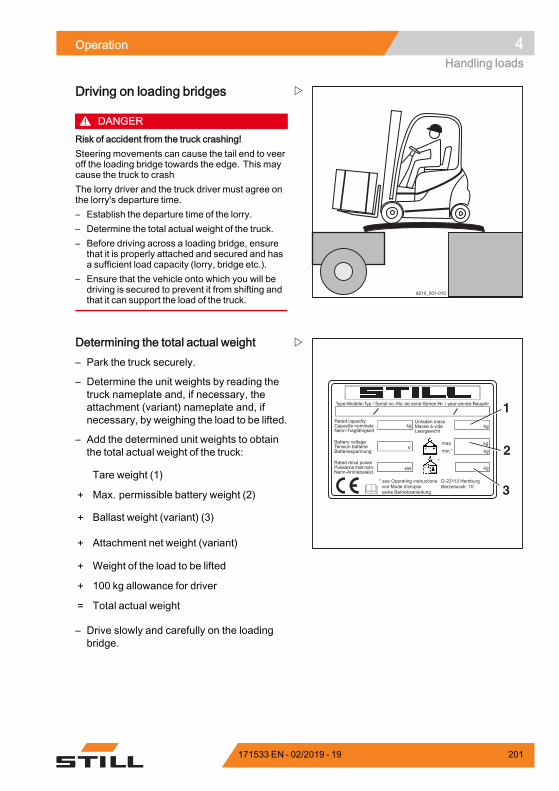
Operation 4Handling loads
6210_001-010
Driving on loading bridges
DANGERRisk of accident from the truck crashing!Steering movements can cause the tail end to veeroff the loading bridge towards the edge. This maycause the truck to crashThe lorry driver and the truck driver must agree onthe lorry's departure time.– Establish the departure time of the lorry.– Determine the total actual weight of the truck.– Before driving across a loading bridge, ensure
that it is properly attached and secured and hasa sufficient load capacity (lorry, bridge etc.).
– Ensure that the vehicle onto which you will bedriving is secured to prevent it from shifting andthat it can support the load of the truck.
Type-Modèle-Typ / Serial no.-No. de série-Serien-Nr. / year-année-Baujahr
Rated capacityCapacité nominaleNenn-Tragfähigkeit
Battery voltageTension batterieBatteriespannung
Rated drive powerPuissance motr.nom.Nenn-Antriebsleist.
Unladen massMasse à videLeergewicht
max
min.*
kg kg
kg
kg
kgkW
V
*
* see Operating instructions voir Mode d'emploi siehe Betriebsanleitung
D-22113 HamburgBerzeliusstr. 10
1
3
2
Determining the total actual weight– Park the truck securely.
– Determine the unit weights by reading thetruck nameplate and, if necessary, theattachment (variant) nameplate and, ifnecessary, by weighing the load to be lifted.
– Add the determined unit weights to obtainthe total actual weight of the truck:
Tare weight (1)
+ Max. permissible battery weight (2)
+ Ballast weight (variant) (3)
+ Attachment net weight (variant)
+ Weight of the load to be lifted
+ 100 kg allowance for driver
= Total actual weight
– Drive slowly and carefully on the loadingbridge.
171533 EN - 02/2019 - 19 201
4 OperationAttachments
AttachmentsFitting attachmentsIf the truck is equipped with an integratedattachment (variant) at the factory, the specifi-cations in the STILL operating instructions forintegrated attachments must be observed.
If attachments are fitted at the place of use,the specifications in the operating instructionsof the attachment manufacturer must beobserved.
If an attachment is not delivered togetherwith the forklift truck, the specifications andoperating instructions of the attachmentmanufacturer must be observed.
Before initial commissioning, the functionof the attachment and the visibility from thedriver's position with and without a load mustbe checked by a competent person. If thevisibility is deemed insufficient, visual aidssuch asmirrors, a camera/monitor system etc.must be used.
In addition, it is essential that the warningsbelow are observed.
CAUTIONAttachments must be CE-certified. If the truck isnot fitted with an attachment-specific residual loadcapacity rating plate and the operating devices arenot marked with corresponding pictograms, thetruck must not be used.– Order the residual load capacity rating plate and
pictograms from your authorised service centrein good time.
– The authorised service centre must adapt thehydraulic system to the requirements of theattachment (e.g. by adjusting the pump motorspeed).
202 171533 EN - 02/2019 - 19
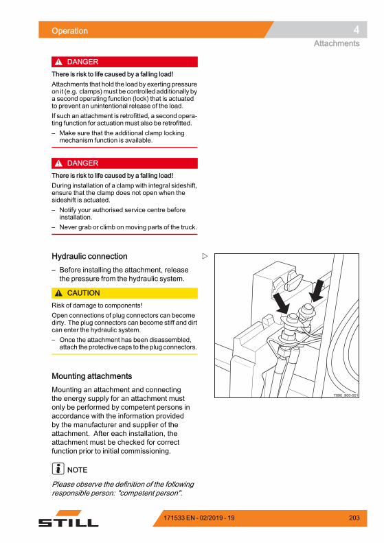
Operation 4Attachments
DANGERThere is risk to life caused by a falling load!Attachments that hold the load by exerting pressureon it (e.g. clamps)must be controlled additionally bya second operating function (lock) that is actuatedto prevent an unintentional release of the load.If such an attachment is retrofitted, a second opera-ting function for actuation must also be retrofitted.– Make sure that the additional clamp locking
mechanism function is available.
DANGERThere is risk to life caused by a falling load!During installation of a clamp with integral sideshift,ensure that the clamp does not open when thesideshift is actuated.– Notify your authorised service centre before
installation.– Never grab or climb on moving parts of the truck.
7090_900-001
Hydraulic connection– Before installing the attachment, releasethe pressure from the hydraulic system.
CAUTIONRisk of damage to components!Open connections of plug connectors can becomedirty. The plug connectors can become stiff and dirtcan enter the hydraulic system.– Once the attachment has been disassembled,
attach theprotective caps to the plug connectors.
Mounting attachmentsMounting an attachment and connectingthe energy supply for an attachment mustonly be performed by competent persons inaccordance with the information providedby the manufacturer and supplier of theattachment. After each installation, theattachment must be checked for correctfunction prior to initial commissioning.
NOTE
Please observe the definition of the followingresponsible person: "competent person".
171533 EN - 02/2019 - 19 203

4 OperationAttachments
Load capacity with attachmentThe permissible load capacity of the attach-ment and the allowable load (load capacityand load moment) of the truck must not be ex-ceeded by the combination of attachment andpayload. The specifications of the manufac-turer and supplier of the attachment must becomplied with.
– Observe the residual load capacity ratingplate, see the chapter entitled "Taking up aload using attachments".
7090_900-001
Releasing the pressure from thehydraulic system
WARNINGThe movements of the load lift system present arisk of crushing.During the process described below, the forkcarriage or the lift mast can only be moved slightly.– Do not reach into or stand below the components
of the load lift system.
Non-clamping attachments are connectedto the third hydraulic circuit via the plugconnectors on the fork carriage and arecontrolled via the "5th hydraulic function".
– Before fitting attachments, the pressuremust be released from the plug connectors(arrows) and the other hydraulic circuits.
Attachments must only be installed by compe-tent persons. The specifications provided bythe manufacturer and supplier of the attach-ments must be observed during installation ofthe attachments.
– Before each use of the attachment, checkand ensure the functions of the installedattachment.
204 171533 EN - 02/2019 - 19
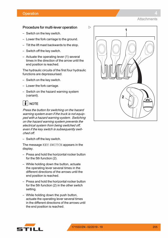
Operation 4Attachments
1
2
Procedure for multi-lever operation– Switch on the key switch.
– Lower the fork carriage to the ground.
– Tilt the lift mast backwards to the stop.
– Switch off the key switch.
– Actuate the operating lever (1) severaltimes in the direction of the arrow until theend position is reached.
The hydraulic circuits of the first four hydraulicfunctions are depressurised.
– Switch on the key switch.
– Lower the fork carriage.
– Switch on the hazard warning system(variant).
NOTE
Press the button for switching on the hazardwarning system even if the truck is not equip-ped with a hazard warning system. Switchingon the hazard warning system prevents theelectrical system from being switched off,even if the key switch is subsequently swit-ched off.
– Switch off the key switch.
The message KEY SWITCH appears in thedisplay.
– Press and hold the horizontal rocker buttonfor the 5th function (2).
– While holding down the button, actuatethe operating lever several times in thedifferent directions of the arrows until theend position is reached.
– Press and hold the horizontal rocker buttonfor the 5th function (2) in the other switchsetting.
– While holding down the push button,actuate the operating lever several timesin the different directions of the arrows untilthe end position is reached.
171533 EN - 02/2019 - 19 205
4 OperationAttachments
The hydraulic circuit of the 5th hydraulicfunction is depressurised. The connectionson the lift mast are depressurised.
NOTE
The number of operating levers shown maydiffer from the truck's equipment.
WARNINGUnintended movement of the lift mast presents arisk of injury.The hydraulic pump is inactive. If an operatingdevice for the hydraulic functions is accidentallyactuated, it may still cause unintended movementsof the lift mast.– Do not touch the operating devices.
206 171533 EN - 02/2019 - 19
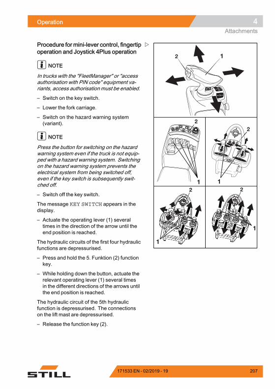
Operation 4Attachments
1
F1F1 F2F2
1
1
F1 F2
1
1
+ F
2
2
2 2
2
Procedure for mini-lever control, fingertipoperation and Joystick 4Plus operation
NOTE
In trucks with the "FleetManager" or "accessauthorisation with PIN code" equipment va-riants, access authorisation must be enabled.
– Switch on the key switch.
– Lower the fork carriage.
– Switch on the hazard warning system(variant).
NOTE
Press the button for switching on the hazardwarning system even if the truck is not equip-ped with a hazard warning system. Switchingon the hazard warning system prevents theelectrical system from being switched off,even if the key switch is subsequently swit-ched off.
– Switch off the key switch.
The message KEY SWITCH appears in thedisplay.
– Actuate the operating lever (1) severaltimes in the direction of the arrow until theend position is reached.
The hydraulic circuits of the first four hydraulicfunctions are depressurised.
– Press and hold the 5. Funktion (2) functionkey.
– While holding down the button, actuate therelevant operating lever (1) several timesin the different directions of the arrows untilthe end position is reached.
The hydraulic circuit of the 5th hydraulicfunction is depressurised. The connectionson the lift mast are depressurised.
– Release the function key (2).
171533 EN - 02/2019 - 19 207
4 OperationAttachments
General instructions for controllingattachmentsThe way in which attachments (variant) arecontrolled depends on the operating devicesincluded in the truck's equipment.
Essentially, a distinction is drawn between:• Multiple-lever• Multiple-lever with a 5th function (variant)• Double mini-lever• Double mini-lever with a 5th function(variant)
• Triple mini-lever• Triplemini-lever with a 5th function (variant)• Quadruple mini-lever• Quadruple mini-lever with a 5th function(variant)
• Joystick 4Plus• Joystick 4Plus with a 5th function (variant)• Fingertip• Fingertip with a 5th function (variant)
– For information on controlling attachmentswith the respective operating devices, seethe relevant sections in this chapter.
WARNINGUse of attachments can give rise to additionalhazards such as a change in the centre of gravity,additional danger areas etc.Attachments must only be used for their intendedpurpose as described in the relevant operatinginstructions. Drivers must be taught how to operatethe attachments.Loads may only be picked up and transportedwith attachments if they are securely grasped andattached. Where necessary, loads must also besecured against slipping, rolling away, falling over,swinging or tipping over. Note that any change tothe position of the load centre of gravity will affectthe stability of the truck.– Refer to the capacity rating plate for the attach-
ments being used.
NOTE
Further variants and functions are available inaddition to the functions described below. The
208 171533 EN - 02/2019 - 19
Operation 4Attachments
directions of movement can be seen on thepictograms on the operating devices.
NOTE
All the attachments described fall into thecategory of equipment variants. Pleasesee the respective operating instructionsfor an exact description of the respectivemovements/actions of the attachment fitted.
171533 EN - 02/2019 - 19 209
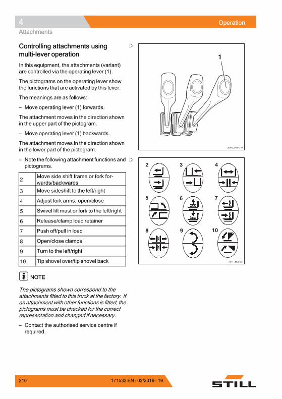
4 OperationAttachments
2060_003-019
1
Controlling attachments usingmulti-lever operationIn this equipment, the attachments (variant)are controlled via the operating lever (1).
The pictograms on the operating lever showthe functions that are activated by this lever.
The meanings are as follows:
– Move operating lever (1) forwards.
The attachment moves in the direction shownin the upper part of the pictogram.
– Move operating lever (1) backwards.
The attachment moves in the direction shownin the lower part of the pictogram.
7311_862-001
2 3
6
4
7
9 10
5
8
– Note the following attachment functions andpictograms.
2 Move side shift frame or fork for-wards/backwards
3 Move sideshift to the left/right
4 Adjust fork arms: open/close
5 Swivel lift mast or fork to the left/right
6 Release/clamp load retainer
7 Push off/pull in load
8 Open/close clamps
9 Turn to the left/right
10 Tip shovel over/tip shovel back
NOTE
The pictograms shown correspond to theattachments fitted to this truck at the factory. Ifan attachment with other functions is fitted, thepictograms must be checked for the correctrepresentation and changed if necessary.
– Contact the authorised service centre ifrequired.
210 171533 EN - 02/2019 - 19
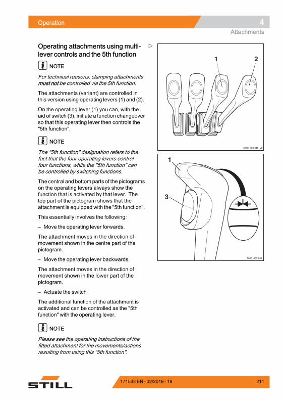
Operation 4Attachments
5060_003-040_V2
21
1
3
5060_003-041
Operating attachments using multi-lever controls and the 5th function
NOTE
For technical reasons, clamping attachmentsmust not be controlled via the 5th function.
The attachments (variant) are controlled inthis version using operating levers (1) and (2).
On the operating lever (1) you can, with theaid of switch (3), initiate a function changeoverso that this operating lever then controls the"5th function".
NOTE
The "5th function" designation refers to thefact that the four operating levers controlfour functions, while the "5th function" canbe controlled by switching functions.
The central and bottomparts of the pictogramson the operating levers always show thefunction that is activated by that lever. Thetop part of the pictogram shows that theattachment is equippedwith the "5th function".
This essentially involves the following:
– Move the operating lever forwards.
The attachment moves in the direction ofmovement shown in the centre part of thepictogram.
– Move the operating lever backwards.
The attachment moves in the direction ofmovement shown in the lower part of thepictogram.
– Actuate the switch
The additional function of the attachment isactivated and can be controlled as the "5thfunction" with the operating lever.
NOTE
Please see the operating instructions of thefitted attachment for the movements/actionsresulting from using this "5th function".
171533 EN - 02/2019 - 19 211
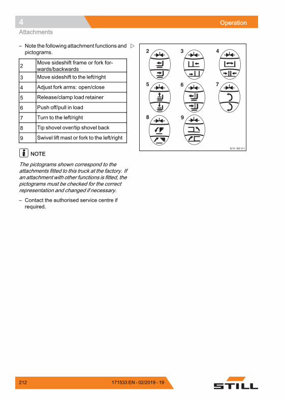
4 OperationAttachments
6210_862-011
2 3
6
4
7
9
5
8
– Note the following attachment functions andpictograms.
2 Move sideshift frame or fork for-wards/backwards
3 Move sideshift to the left/right
4 Adjust fork arms: open/close
5 Release/clamp load retainer
6 Push off/pull in load
7 Turn to the left/right
8 Tip shovel over/tip shovel back
9 Swivel lift mast or fork to the left/right
NOTE
The pictograms shown correspond to theattachments fitted to this truck at the factory. Ifan attachment with other functions is fitted, thepictograms must be checked for the correctrepresentation and changed if necessary.
– Contact the authorised service centre ifrequired.
212 171533 EN - 02/2019 - 19
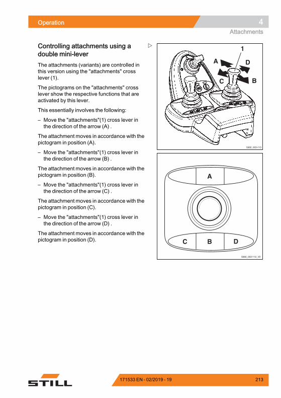
Operation 4Attachments
5060_003-113
A
C B
D
1
5060_003-112_V2
A
C B D
Controlling attachments using adouble mini-leverThe attachments (variants) are controlled inthis version using the "attachments" crosslever (1).
The pictograms on the "attachments" crosslever show the respective functions that areactivated by this lever.
This essentially involves the following:
– Move the "attachments"(1) cross lever inthe direction of the arrow (A) .
The attachment moves in accordance with thepictogram in position (A).
– Move the "attachments"(1) cross lever inthe direction of the arrow (B) .
The attachment moves in accordance with thepictogram in position (B).
– Move the "attachments"(1) cross lever inthe direction of the arrow (C) .
The attachment moves in accordance with thepictogram in position (C).
– Move the "attachments"(1) cross lever inthe direction of the arrow (D) .
The attachment moves in accordance with thepictogram in position (D).
171533 EN - 02/2019 - 19 213

4 OperationAttachments
7312_003-099
3 5
11
7
4 6
13
17 19
9
12 1410
15
18 2016
8
– Note the following attachment functions andpictograms.
3 Move sideshift frame or fork forwards
4 Move sideshift frame or fork back-wards
5 Move sideshift to the left
6 Move sideshift to the right
7 Adjust fork arms: open
8 Adjust fork arms: close
9 Swivel lift mast or fork to the left
10 Swivel lift mast or fork to the right
11 Release load retainer
12 Clamp load retainer
13 Push off the load
14 Pull in the load
15 Open clamps
16 Close clamps
17 Rotate to the left
18 Rotate to the right
19 Tip shovel over
20 Tip shovel back
NOTE
The pictograms shown correspond to theattachments fitted to this truck at the factory. Ifan attachment with other functions is fitted, thepictograms must be checked for the correctrepresentation and changed if necessary.
– Contact the authorised service centre ifrequired.
214 171533 EN - 02/2019 - 19
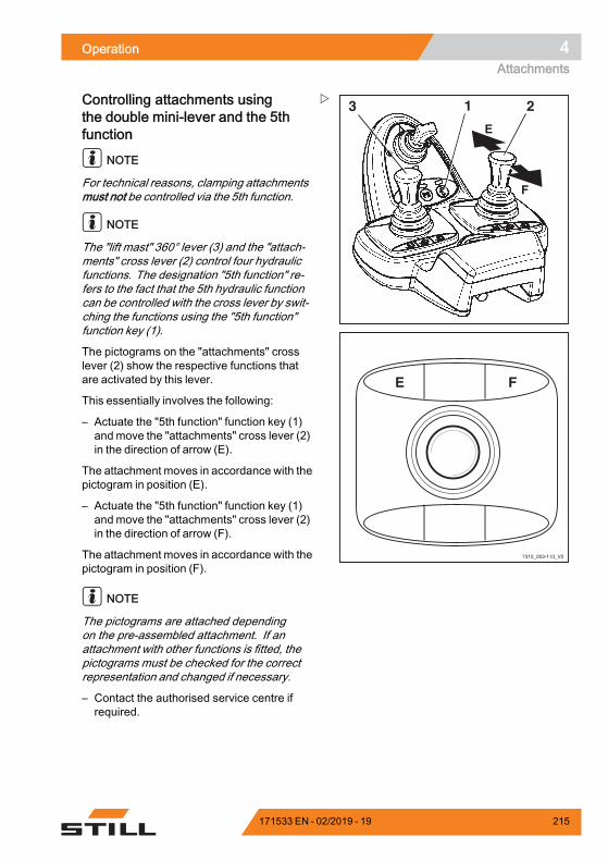
Operation 4Attachments
2
E
F
13
7312_003-113_V2
E F
Controlling attachments usingthe double mini-lever and the 5thfunction
NOTE
For technical reasons, clamping attachmentsmust not be controlled via the 5th function.
NOTE
The "lift mast" 360° lever (3) and the "attach-ments" cross lever (2) control four hydraulicfunctions. The designation "5th function" re-fers to the fact that the 5th hydraulic functioncan be controlled with the cross lever by swit-ching the functions using the "5th function"function key (1).
The pictograms on the "attachments" crosslever (2) show the respective functions thatare activated by this lever.
This essentially involves the following:
– Actuate the "5th function" function key (1)and move the "attachments" cross lever (2)in the direction of arrow (E).
The attachment moves in accordance with thepictogram in position (E).
– Actuate the "5th function" function key (1)and move the "attachments" cross lever (2)in the direction of arrow (F).
The attachment moves in accordance with thepictogram in position (F).
NOTE
The pictograms are attached dependingon the pre-assembled attachment. If anattachment with other functions is fitted, thepictograms must be checked for the correctrepresentation and changed if necessary.
– Contact the authorised service centre ifrequired.
171533 EN - 02/2019 - 19 215
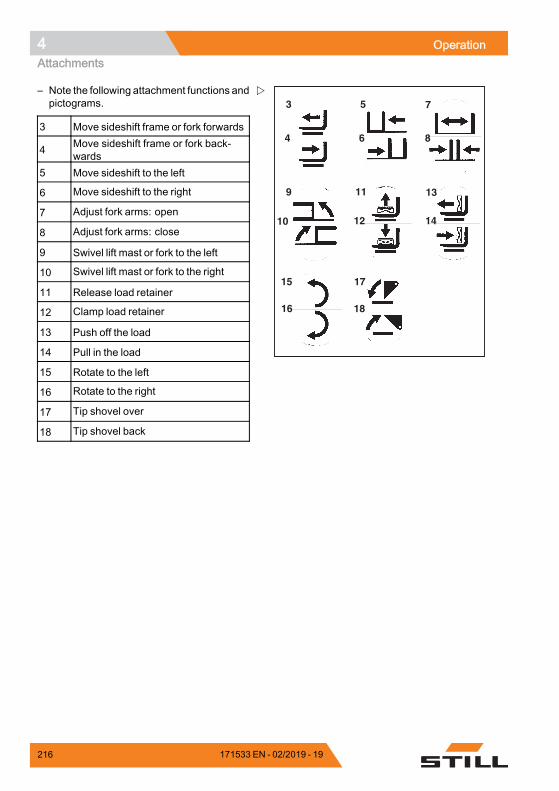
4 OperationAttachments
3 5
11
7
4 6
13
15 17
9
12 1410
16 18
8
– Note the following attachment functions andpictograms.
3 Move sideshift frame or fork forwards
4 Move sideshift frame or fork back-wards
5 Move sideshift to the left
6 Move sideshift to the right
7 Adjust fork arms: open
8 Adjust fork arms: close
9 Swivel lift mast or fork to the left
10 Swivel lift mast or fork to the right
11 Release load retainer
12 Clamp load retainer
13 Push off the load
14 Pull in the load
15 Rotate to the left
16 Rotate to the right
17 Tip shovel over
18 Tip shovel back.
216 171533 EN - 02/2019 - 19
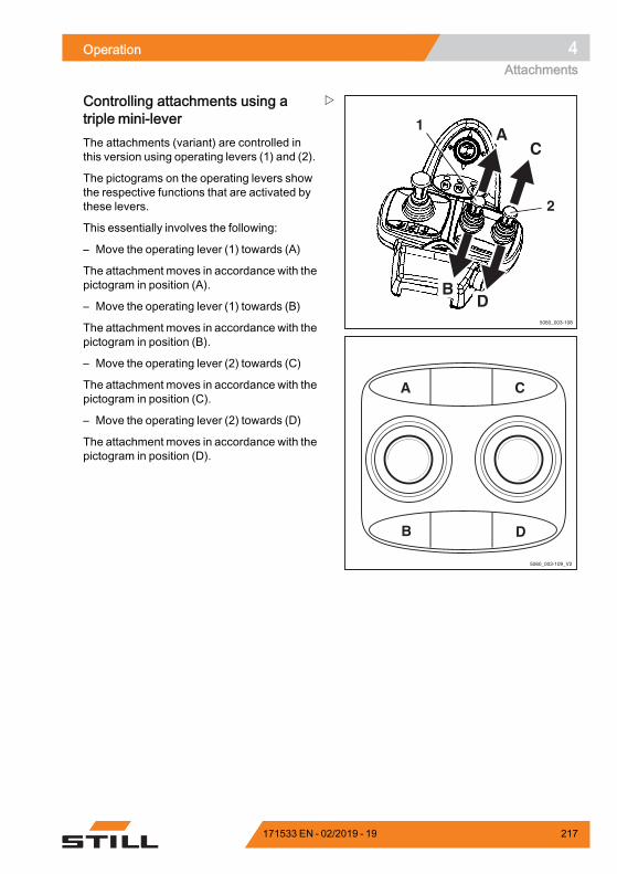
Operation 4Attachments
5060_003-108
1
2
AC
BD
5060_003-109_V2
A C
B D
Controlling attachments using atriple mini-leverThe attachments (variant) are controlled inthis version using operating levers (1) and (2).
The pictograms on the operating levers showthe respective functions that are activated bythese levers.
This essentially involves the following:
– Move the operating lever (1) towards (A)
The attachment moves in accordance with thepictogram in position (A).
– Move the operating lever (1) towards (B)
The attachment moves in accordance with thepictogram in position (B).
– Move the operating lever (2) towards (C)
The attachment moves in accordance with thepictogram in position (C).
– Move the operating lever (2) towards (D)
The attachment moves in accordance with thepictogram in position (D).
171533 EN - 02/2019 - 19 217

4 OperationAttachments
7312_003-099
3 5
11
7
4 6
13
17 19
9
12 1410
15
18 2016
8
– Note the following attachment functions andpictograms.
3 Move sideshift frame or fork forwards
4 Move sideshift frame or fork back-wards
5 Move sideshift to the left
6 Move sideshift to the right
7 Adjust fork arms: open
8 Adjust fork arms: close
9 Swivel lift mast or fork to the left
10 Swivel lift mast or fork to the right
11 Release load retainer
12 Clamp load retainer
13 Push off the load
14 Pull in the load
15 Open clamps
16 Close clamps
17 Rotate to the left
18 Rotate to the right
19 Tip shovel over
20 Tip shovel back
NOTE
The pictograms shown correspond to theattachments fitted to this truck at the factory. Ifan attachment with other functions is fitted, thepictograms must be checked for the correctrepresentation and changed if necessary.
– Contact the authorised service centre ifrequired.
218 171533 EN - 02/2019 - 19
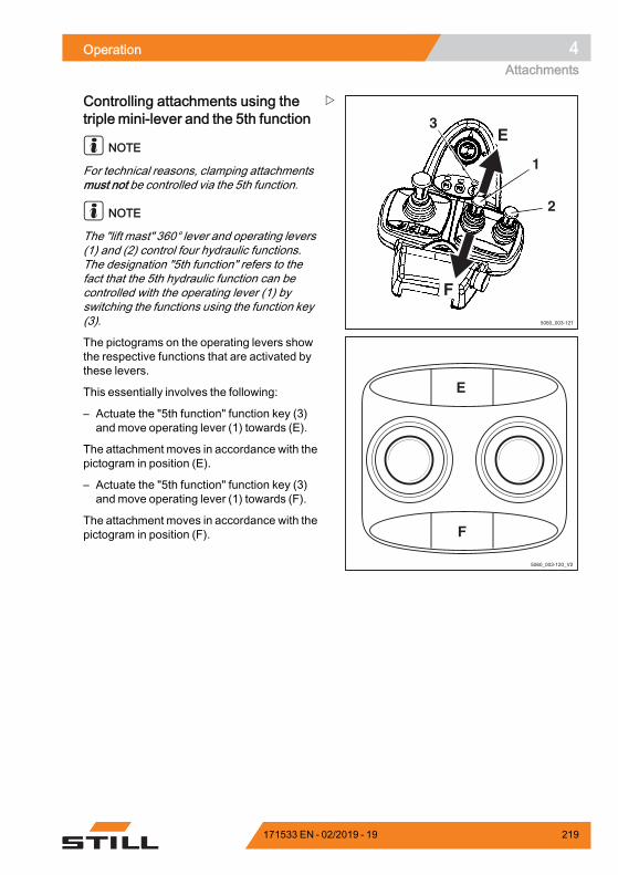
Operation 4Attachments
5060_003-121
E
F
2
1
3
5060_003-120_V2
E
F
Controlling attachments using thetriple mini-lever and the 5th function
NOTE
For technical reasons, clamping attachmentsmust not be controlled via the 5th function.
NOTE
The "lift mast" 360° lever and operating levers(1) and (2) control four hydraulic functions.The designation "5th function" refers to thefact that the 5th hydraulic function can becontrolled with the operating lever (1) byswitching the functions using the function key(3).
The pictograms on the operating levers showthe respective functions that are activated bythese levers.
This essentially involves the following:
– Actuate the "5th function" function key (3)and move operating lever (1) towards (E).
The attachment moves in accordance with thepictogram in position (E).
– Actuate the "5th function" function key (3)and move operating lever (1) towards (F).
The attachment moves in accordance with thepictogram in position (F).
171533 EN - 02/2019 - 19 219

4 OperationAttachments
5060_003-122
3
4
1
2
– Note the following attachment functions andpictograms.
1 Adjust fork arms: open
2 Adjust fork arms: close
3 Rotate to the left
4 Rotate to the right
NOTE
The pictograms shown correspond to theattachments fitted to this truck at the factory. Ifan attachment with other functions is fitted, thepictograms must be checked for the correctrepresentation and changed if necessary.
– Contact the authorised service centre ifrequired.
220 171533 EN - 02/2019 - 19
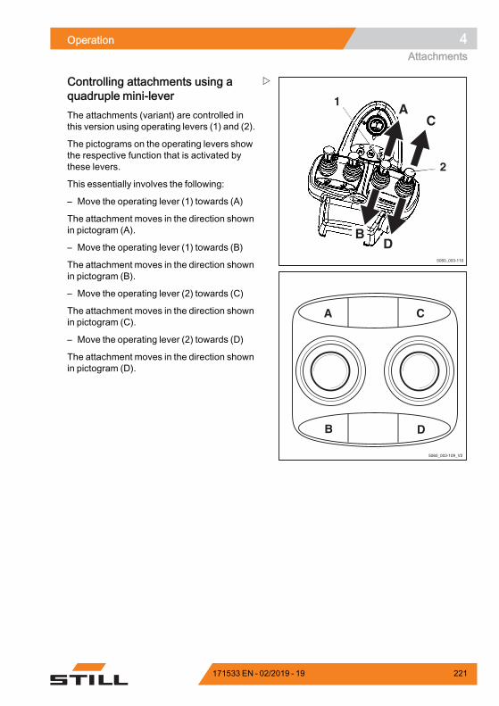
Operation 4Attachments
5060_003-110
1
2
AC
BD
5060_003-109_V2
A C
B D
Controlling attachments using aquadruple mini-leverThe attachments (variant) are controlled inthis version using operating levers (1) and (2).
The pictograms on the operating levers showthe respective function that is activated bythese levers.
This essentially involves the following:
– Move the operating lever (1) towards (A)
The attachment moves in the direction shownin pictogram (A).
– Move the operating lever (1) towards (B)
The attachment moves in the direction shownin pictogram (B).
– Move the operating lever (2) towards (C)
The attachment moves in the direction shownin pictogram (C).
– Move the operating lever (2) towards (D)
The attachment moves in the direction shownin pictogram (D).
171533 EN - 02/2019 - 19 221
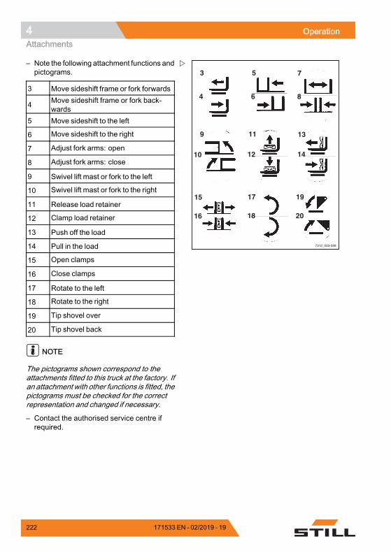
4 OperationAttachments
7312_003-099
3 5
11
7
4 6
13
17 19
9
12 1410
15
18 2016
8
– Note the following attachment functions andpictograms.
3 Move sideshift frame or fork forwards
4 Move sideshift frame or fork back-wards
5 Move sideshift to the left
6 Move sideshift to the right
7 Adjust fork arms: open
8 Adjust fork arms: close
9 Swivel lift mast or fork to the left
10 Swivel lift mast or fork to the right
11 Release load retainer
12 Clamp load retainer
13 Push off the load
14 Pull in the load
15 Open clamps
16 Close clamps
17 Rotate to the left
18 Rotate to the right
19 Tip shovel over
20 Tip shovel back
NOTE
The pictograms shown correspond to theattachments fitted to this truck at the factory. Ifan attachment with other functions is fitted, thepictograms must be checked for the correctrepresentation and changed if necessary.
– Contact the authorised service centre ifrequired.
222 171533 EN - 02/2019 - 19
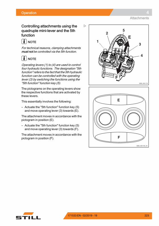
Operation 4Attachments
5060_003-119
4
1
25
3
E
F
5060_003-120_V2
E
F
Controlling attachments using thequadruple mini-lever and the 5thfunction
NOTE
For technical reasons, clamping attachmentsmust not be controlled via the 5th function.
NOTE
Operating levers (1) to (4) are used to controlfour hydraulic functions. The designation "5thfunction" refers to the fact that the 5th hydraulicfunction can be controlled with the operatinglever (3) by switching the functions using the"5th function" function key (5).
The pictograms on the operating levers showthe respective functions that are activated bythese levers.
This essentially involves the following:
– Actuate the "5th function" function key (5)and move operating lever (3) towards (E).
The attachment moves in accordance with thepictogram in position (E).
– Actuate the "5th function" function key (5)and move operating lever (3) towards (F).
The attachment moves in accordance with thepictogram in position (F).
171533 EN - 02/2019 - 19 223
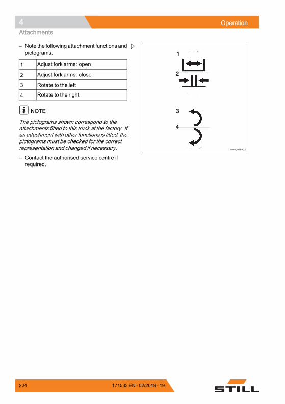
4 OperationAttachments
5060_003-122
3
4
1
2
– Note the following attachment functions andpictograms.
1 Adjust fork arms: open
2 Adjust fork arms: close
3 Rotate to the left
4 Rotate to the right
NOTE
The pictograms shown correspond to theattachments fitted to this truck at the factory. Ifan attachment with other functions is fitted, thepictograms must be checked for the correctrepresentation and changed if necessary.
– Contact the authorised service centre ifrequired.
224 171533 EN - 02/2019 - 19
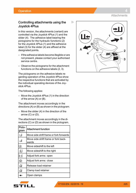
Operation 4Attachments
6219_003-206
A
D
C
B1
42
3
Controlling attachments using theJoystick 4PlusIn this version, the attachments (variant) arecontrolled via the Joystick 4Plus (1) and theslider (4). The adhesive label bearing thepictograms for the hydraulic functions (2)for the Joystick 4Plus (1) and the adhesivelabel (3) for the slider (4) are affixed at thedesignated points.
– If theadhesive labels become illegible or arenot present, please contact your authorisedservice centre.
– Observe the pictograms for the attachmentfunctions on the adhesive labels (2, 3).
The pictograms on the adhesive labels re-garding operation of the Joystick 4Plus showthe respective functions that are activated bythe individual operating devices of the Joy-stick 4Plus.
The following applies:
– Move the Joystick 4Plus (1) in the directionof the arrow (A) or (B).
The attachment moves accordingly in thedirections (A) or (B) as shown in the pictogram.
– Move the slider (4) in the direction of thearrow (C) or (D).
The attachment moves accordingly in the di-rections (C) or (D) as shown in the pictogram.
Picto-gram Attachment function
Move side shift frame or fork forwardsMove side shift frame or fork back-wardsMove sideshift to the left
Move sideshift to the right
Adjust fork arms: open
Adjust fork arms: close
Release load retainer
Clamp load retainer
Open clamps
171533 EN - 02/2019 - 19 225
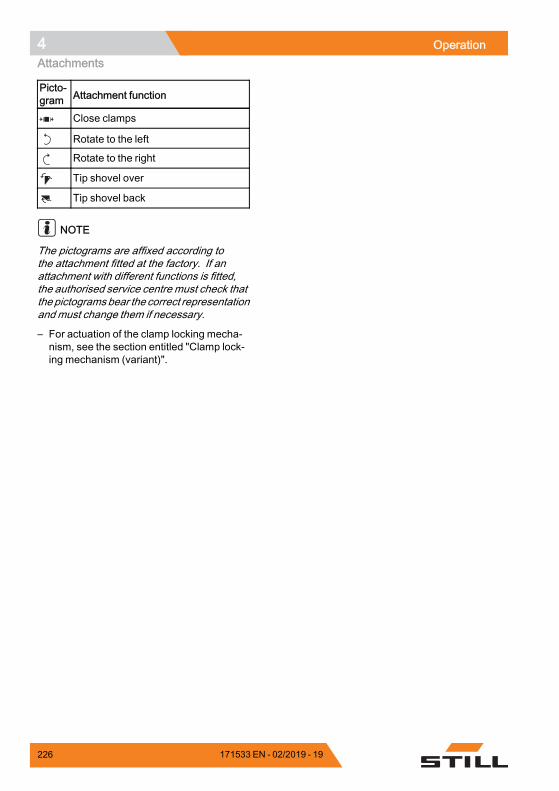
4 OperationAttachments
Picto-gram Attachment function
Close clamps
Rotate to the left
Rotate to the right
Tip shovel over
Tip shovel back
NOTE
The pictograms are affixed according tothe attachment fitted at the factory. If anattachment with different functions is fitted,the authorised service centre must check thatthe pictogramsbear the correct representationand must change them if necessary.
– For actuation of the clamp locking mecha-nism, see the section entitled "Clamp lock-ing mechanism (variant)".
226 171533 EN - 02/2019 - 19
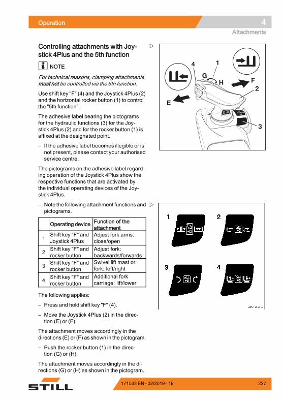
Operation 4Attachments
6219_003-166_V2
3
E
GH F
14
2
Controlling attachments with Joy-stick 4Plus and the 5th function
NOTE
For technical reasons, clamping attachmentsmust not be controlled via the 5th function.
Use shift key "F" (4) and the Joystick 4Plus (2)and the horizontal rocker button (1) to controlthe "5th function".
The adhesive label bearing the pictogramsfor the hydraulic functions (3) for the Joy-stick 4Plus (2) and for the rocker button (1) isaffixed at the designated point.
– If the adhesive label becomes illegible or isnot present, please contact your authorisedservice centre.
The pictograms on the adhesive label regard-ing operation of the Joystick 4Plus show therespective functions that are activated bythe individual operating devices of the Joy-stick 4Plus.
– Note the following attachment functions andpictograms.
Operating device Function of theattachment
1Shift key "F" andJoystick 4Plus
Adjust fork arms:close/open
2 Shift key "F" androcker button
Adjust fork:backwards/forwards
3 Shift key "F" androcker button
Swivel lift mast orfork: left/right
4 Shift key "F" androcker button
Additional forkcarriage: lift/lower
The following applies:
– Press and hold shift key "F" (4).
– Move the Joystick 4Plus (2) in the direc-tion (E) or (F).
The attachment moves accordingly in thedirections (E) or (F) as shown in the pictogram.
– Push the rocker button (1) in the direc-tion (G) or (H).
The attachment moves accordingly in the di-rections (G) or (H) as shown in the pictogram.
171533 EN - 02/2019 - 19 227
4 OperationAttachments
– Release shift key "F" (4).
NOTE
The pictograms are affixed according tothe attachment fitted at the factory. If anattachment with different functions is fitted,the authorised service centre must check thatthe pictogramsbear the correct representationand must change them if necessary.
228 171533 EN - 02/2019 - 19
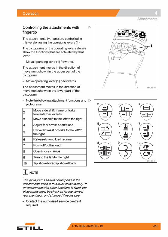
Operation 4Attachments
F1F1 F2F2
6321_003-013
1
Controlling the attachments withfingertipThe attachments (variant) are controlled inthis version using the operating levers (1).
Thepictogramson theoperating levers alwaysshow the functions that are activated by thatlever.
– Move operating lever (1) forwards.
The attachment moves in the direction ofmovement shown in the upper part of thepictogram.
– Move operating lever (1) backwards.
The attachment moves in the direction ofmovement shown in the lower part of thepictogram.
6210_003-031
2 3
6
4
7
9 10
5
8
– Note the following attachment functions andpictograms.
2 Move side shift frame or forksforwards/backwards
3 Move sideshift to the left/to the right
4 Adjust fork arms: open/close
5Swivel lift mast or forks to the left/tothe right
6 Release/clamp load retainer
7 Push off/pull in load
8 Open/close clamps
9 Turn to the left/to the right
10 Tip shovel over/tip shovel back
NOTE
The pictograms shown correspond to theattachments fitted to this truck at the factory. Ifan attachment with other functions is fitted, thepictograms must be checked for the correctrepresentation and changed if necessary.
– Contact the authorised service centre ifrequired.
171533 EN - 02/2019 - 19 229
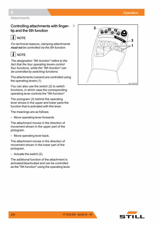
4 OperationAttachments
F1F1 F2F2
6210_003-032
13
2Controlling attachments with finger-tip and the 5th function
NOTE
For technical reasons, clamping attachmentsmust not be controlled via the 5th function.
NOTE
The designation "5th function" refers to thefact that the four operating levers controlfour functions, while the "5th function" canbe controlled by switching functions.
The attachments (variant) are controlled usingthe operating levers (1).
You can also use the switch (2) to switchfunctions, in which case the correspondingoperating lever controls the "5th function".
The pictogram (3) behind the operatinglever shows in the upper and lower parts thefunction that is activated with this lever.
The meanings are as follows:
– Move operating lever forwards.
The attachment moves in the direction ofmovement shown in the upper part of thepictogram.
– Move operating lever back.
The attachment moves in the direction ofmovement shown in the lower part of thepictogram.
– Actuate the switch (2).
The additional function of the attachment isactivated/deactivated and can be controlledas the "5th function" using the operating lever.
230 171533 EN - 02/2019 - 19
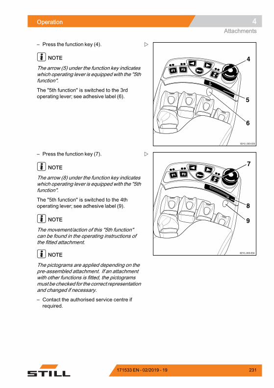
Operation 4Attachments
F1F1 F2F2
6210_003-033
4
5
6
– Press the function key (4).
NOTE
The arrow (5) under the function key indicateswhich operating lever is equippedwith the "5thfunction".
The "5th function" is switched to the 3rdoperating lever; see adhesive label (6).
F1F1 F2F2
6210_003-034
7
8
9
– Press the function key (7).
NOTE
The arrow (8) under the function key indicateswhich operating lever is equippedwith the "5thfunction".
The "5th function" is switched to the 4thoperating lever; see adhesive label (9).
NOTE
The movement/action of this "5th function"can be found in the operating instructions ofthe fitted attachment.
NOTE
The pictograms are applied depending on thepre-assembled attachment. If an attachmentwith other functions is fitted, the pictogramsmust be checked for the correct representationand changed if necessary.
– Contact the authorised service centre ifrequired.
171533 EN - 02/2019 - 19 231
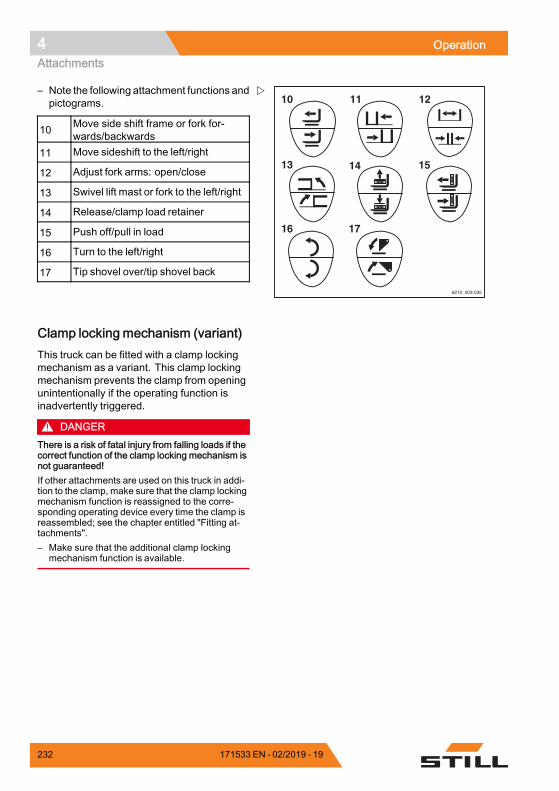
4 OperationAttachments
6210_003-035
10 11
14
12
15
17
13
16
– Note the following attachment functions andpictograms.
10 Move side shift frame or fork for-wards/backwards
11 Move sideshift to the left/right
12 Adjust fork arms: open/close
13 Swivel lift mast or fork to the left/right
14 Release/clamp load retainer
15 Push off/pull in load
16 Turn to the left/right
17 Tip shovel over/tip shovel back.
Clamp locking mechanism (variant)This truck can be fitted with a clamp lockingmechanism as a variant. This clamp lockingmechanism prevents the clamp from openingunintentionally if the operating function isinadvertently triggered.
DANGERThere is a risk of fatal injury from falling loads if thecorrect function of the clamp locking mechanism isnot guaranteed!If other attachments are used on this truck in addi-tion to the clamp, make sure that the clamp lockingmechanism function is reassigned to the corre-sponding operating device every time the clamp isreassembled; see the chapter entitled "Fitting at-tachments".– Make sure that the additional clamp locking
mechanism function is available.
232 171533 EN - 02/2019 - 19
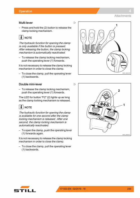
Operation 4Attachments
6210_003-076
1
2
Multi-lever– Press and hold the (2) button to release theclamp locking mechanism.
NOTE
The hydraulic function for opening the clampis only available if the button is pressed.After releasing the button, the clamp lockingmechanism is automatically reactivated.
– To release the clamp locking mechanism,push the operating lever (1) forwards.
It is not necessary to release the clamp lockingmechanism in order to close the clamp.
– To close the clamp, pull the operating lever(1) backwards.
F1 F2
6210_003-077
1
2
Double mini-lever– To release the clamp locking mechanism,push the operating lever (1) forwards.
The LED for button "F2" (2) lights up as longas the clamp locking mechanism is released.
NOTE
The hydraulic function for opening the clampis available for one second after the clamplocking mechanism is released. After onesecond, the clamp locking mechanism isautomatically reactivated.
– To open the clamp, push the operating lever(1) forwards again.
It is not necessary to release the clamp lockingmechanism in order to close the clamp.
– To close the clamp, pull the operating lever(1) backwards.
171533 EN - 02/2019 - 19 233
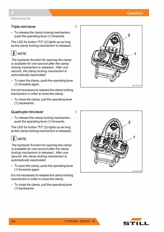
4 OperationAttachments
6210_003-078
1
2
Triple mini-lever– To release the clamp locking mechanism,push the operating lever (1) forwards.
The LED for button "F2" (2) lights up as longas the clamp locking mechanism is released.
NOTE
The hydraulic function for opening the clampis available for one second after the clamplocking mechanism is released. After onesecond, the clamp locking mechanism isautomatically reactivated.
– To open the clamp, push the operating lever(1) forwards again.
It is not necessary to release the clamp lockingmechanism in order to close the clamp.
– To close the clamp, pull the operating lever(1) backwards.
6210_003-079
2
1
Quadruple mini-lever– To release the clamp locking mechanism,push the operating lever (1) forwards.
The LED for button "F2" (2) lights up as longas the clamp locking mechanism is released.
NOTE
The hydraulic function for opening the clampis available for one second after the clamplocking mechanism is released. After onesecond, the clamp locking mechanism isautomatically reactivated.
– To open the clamp, push the operating lever(1) forwards again.
It is not necessary to release the clamp lockingmechanism in order to close the clamp.
– To close the clamp, pull the operating lever(1) backwards.
234 171533 EN - 02/2019 - 19
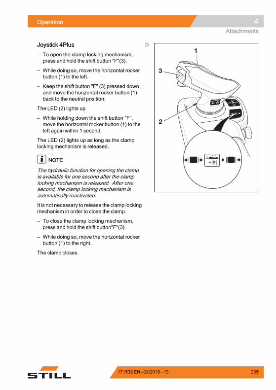
Operation 4Attachments
+ F
+ F
1
3
2
Joystick 4Plus– To open the clamp locking mechanism,press and hold the shift button "F"(3).
– While doing so, move the horizontal rockerbutton (1) to the left.
– Keep the shift button "F" (3) pressed downand move the horizontal rocker button (1)back to the neutral position.
The LED (2) lights up.
– While holding down the shift button "F",move the horizontal rocker button (1) to theleft again within 1 second.
The LED (2) lights up as long as the clamplocking mechanism is released.
NOTE
The hydraulic function for opening the clampis available for one second after the clamplocking mechanism is released. After onesecond, the clamp locking mechanism isautomatically reactivated.
It is not necessary to release the clamp lockingmechanism in order to close the clamp.
– To close the clamp locking mechanism,press and hold the shift button"F"(3).
– While doing so, move the horizontal rockerbutton (1) to the right.
The clamp closes.
171533 EN - 02/2019 - 19 235
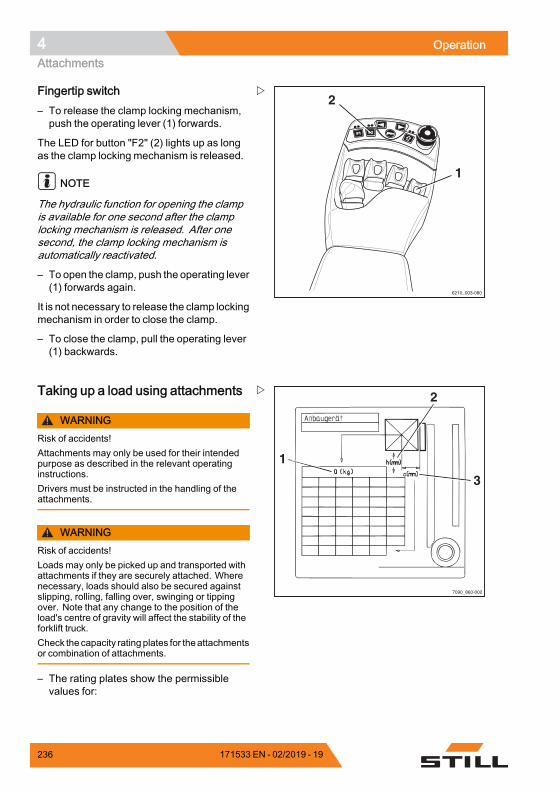
4 OperationAttachments
6210_003-080
F1F1 F2F2
1
2Fingertip switch– To release the clamp locking mechanism,push the operating lever (1) forwards.
The LED for button "F2" (2) lights up as longas the clamp locking mechanism is released.
NOTE
The hydraulic function for opening the clampis available for one second after the clamplocking mechanism is released. After onesecond, the clamp locking mechanism isautomatically reactivated.
– To open the clamp, push the operating lever(1) forwards again.
It is not necessary to release the clamp lockingmechanism in order to close the clamp.
– To close the clamp, pull the operating lever(1) backwards.
1
2
3
7090_860-002
Taking up a load using attachments
WARNINGRisk of accidents!Attachments may only be used for their intendedpurpose as described in the relevant operatinginstructions.Drivers must be instructed in the handling of theattachments.
WARNINGRisk of accidents!Loads may only be picked up and transported withattachments if they are securely attached. Wherenecessary, loads should also be secured againstslipping, rolling, falling over, swinging or tippingover. Note that any change to the position of theload's centre of gravity will affect the stability of theforklift truck.Check the capacity rating plates for theattachmentsor combination of attachments.
– The rating plates show the permissiblevalues for:
236 171533 EN - 02/2019 - 19
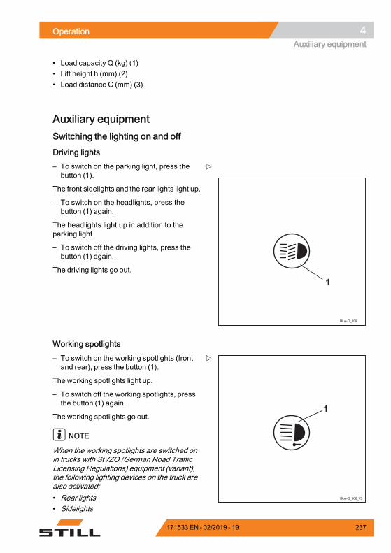
Operation 4Auxiliary equipment
• Load capacity Q (kg) (1)• Lift height h (mm) (2)• Load distance C (mm) (3)
Auxiliary equipmentSwitching the lighting on and off
Driving lights
Blue-Q_039
1
– To switch on the parking light, press thebutton (1).
The front sidelights and the rear lights light up.
– To switch on the headlights, press thebutton (1) again.
The headlights light up in addition to theparking light.
– To switch off the driving lights, press thebutton (1) again.
The driving lights go out.
Working spotlights
Blue-Q_008_V3
1
– To switch on the working spotlights (frontand rear), press the button (1).
The working spotlights light up.
– To switch off the working spotlights, pressthe button (1) again.
The working spotlights go out.
NOTE
When the working spotlights are switched onin trucks with StVZO (German Road TrafficLicensing Regulations) equipment (variant),the following lighting devices on the truck arealso activated:• Rear lights• Sidelights
171533 EN - 02/2019 - 19 237
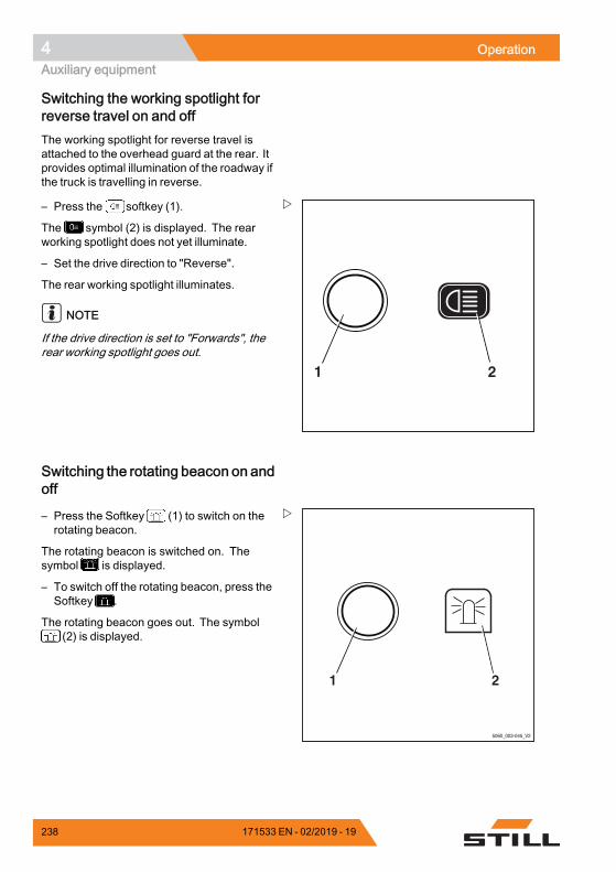
4 OperationAuxiliary equipment
Switching the working spotlight forreverse travel on and offThe working spotlight for reverse travel isattached to the overhead guard at the rear. Itprovides optimal illumination of the roadway ifthe truck is travelling in reverse.
21
– Press the softkey (1).
The symbol (2) is displayed. The rearworking spotlight does not yet illuminate.
– Set the drive direction to "Reverse".
The rear working spotlight illuminates.
NOTE
If the drive direction is set to "Forwards", therear working spotlight goes out.
Switching the rotating beacon on andoff
5060_003-045_V2
21
– Press the Softkey (1) to switch on therotating beacon.
The rotating beacon is switched on. Thesymbol is displayed.
– To switch off the rotating beacon, press theSoftkey .
The rotating beacon goes out. The symbol(2) is displayed.
238 171533 EN - 02/2019 - 19
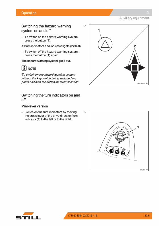
Operation 4Auxiliary equipment
5060_003-011_V2
1
2
Switching the hazard warningsystem on and off– To switch on the hazard warning system,press the button (1).
All turn indicators and indicator lights (2) flash.
– To switch off the hazard warning system,press the button (1) again.
The hazard warning system goes out.
NOTE
To switch on the hazard warning systemwithout the key switch being switched on,press and hold the button for three seconds.
Switching the turn indicators on andoff
Mini-lever version
5060_003-096
F1 F2
1
– Switch on the turn indicators by movingthe cross lever of the drive direction/turnindicator (1) to the left or to the right.
171533 EN - 02/2019 - 19 239
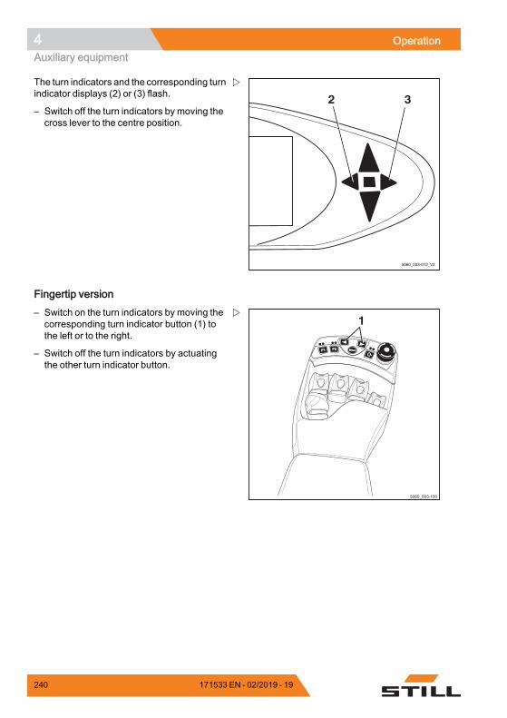
4 OperationAuxiliary equipment
2 3
5060_003-012_V2
The turn indicators and the corresponding turnindicator displays (2) or (3) flash.
– Switch off the turn indicators by moving thecross lever to the centre position.
Fingertip version
F1F1 F2F2
5060_003-100
1– Switch on the turn indicators by moving thecorresponding turn indicator button (1) tothe left or to the right.
– Switch off the turn indicators by actuatingthe other turn indicator button.
240 171533 EN - 02/2019 - 19
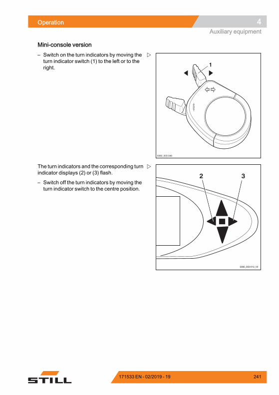
Operation 4Auxiliary equipment
Mini-console version
5060_003-046
1
– Switch on the turn indicators by moving theturn indicator switch (1) to the left or to theright.
2 3
5060_003-012_V2
The turn indicators and the corresponding turnindicator displays (2) or (3) flash.
– Switch off the turn indicators by moving theturn indicator switch to the centre position.
171533 EN - 02/2019 - 19 241
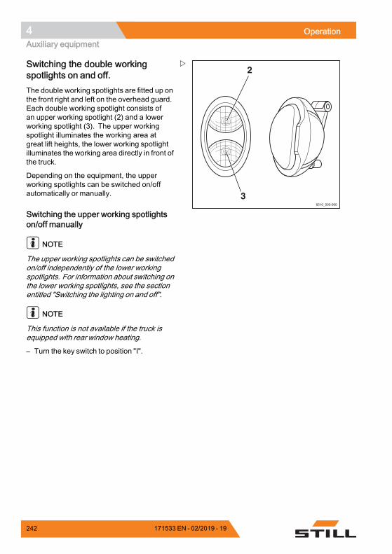
4 OperationAuxiliary equipment
6210_003-060
2
3
Switching the double workingspotlights on and off.The double working spotlights are fitted up onthe front right and left on the overhead guard.Each double working spotlight consists ofan upper working spotlight (2) and a lowerworking spotlight (3). The upper workingspotlight illuminates the working area atgreat lift heights, the lower working spotlightilluminates the working area directly in front ofthe truck.
Depending on the equipment, the upperworking spotlights can be switched on/offautomatically or manually.
Switching the upper working spotlightson/off manually
NOTE
The upper working spotlights can be switchedon/off independently of the lower workingspotlights. For information about switching onthe lower working spotlights, see the sectionentitled "Switching the lighting on and off".
NOTE
This function is not available if the truck isequipped with rear window heating.
– Turn the key switch to position "I".
242 171533 EN - 02/2019 - 19
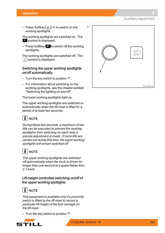
Operation 4Auxiliary equipment
6311_003-030_V3
1
– Press Softkey (1) to switch on theworking spotlights.
The working spotlights are switched on. Thesymbol is displayed.
– Press Softkey to switch off the workingspotlights.
The working spotlights are switched off. Thesymbol is displayed.
Switching the upper working spotlightson/off automatically– Turn the key switch to position "I".
– For information about switching on theworking spotlights, see the chapter entitled"Switching the lighting on and off".
The lower working spotlights light up.
The upper working spotlights are switched onautomatically when the lift mast is lifted for aperiod of at least two seconds.
NOTE
During these two seconds, a maximum of twolifts can be executed to prevent the workingspotlights from switching on each time aprecise adjustment is made. If more lifts arecarried out during this time, the upper workingspotlights will remain switched off.
NOTE
The upper working spotlights are switchedoff automatically when the truck is driven forlonger than one second at a speed faster than2.1 km/h.
Lift-height-controlled switching on/off ofthe upper working spotlights
NOTE
This equipment is available only if a proximityswitch is fitted to the lift mast to record aparticular lift height of the fork carriage onthe lift mast.
– Turn the key switch to position "I".
171533 EN - 02/2019 - 19 243
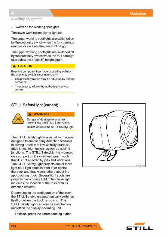
4 OperationAuxiliary equipment
– Switch on the working spotlights.
The lower working spotlights light up.
The upper working spotlights are switched onby the proximity switch when the fork carriagereaches or exceeds the preset lift height.
The upper working spotlights are switched offby the proximity switch when the fork carriagefalls below the preset lift height again.
CAUTIONPossible component damage caused by collision ifthe proximity switch is set incorrectly.– The proximity switch may be adjusted by trained
personnel.– If necessary, inform the authorised service
centre.
STILL SafetyLight (variant)
WARNINGDanger of damage to eyes fromlooking into the STILL SafetyLight.Do not look into theSTILLSafetyLight.
The STILL SafetyLight is a visual warning unitdesigned to enable early detection of trucksin driving areas with low visibility (such asdrive lanes, high racks), as well as at blindjunctions. The STILL SafetyLight is mountedon a support on the overhead guard suchthat it is not affected by jolts and vibrations.The STILL SafetyLight projects one or morelight-blue light spots in front of or behindthe truck and thus warns others about theapproaching truck. Several light spots areprojected as a chase light. The chase lightindicates the location of the truck with itsdirection of travel.
Depending on the configuration of the truck,the STILL SafetyLight automatically switchesitself on when the truck is moving. TheSTILL SafetyLight can also be switched onand off on the display-operating unit.
– To do so, press the corresponding button.
244 171533 EN - 02/2019 - 19
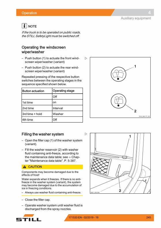
Operation 4Auxiliary equipment
NOTE
If the truck is to be operated on public roads,the STILL SafetyLight must be switched off.
Operating the windscreenwiper/washer
7312_003-171_V3
1
2
– Push button (1) to actuate the front wind-screen wiper/washer (variant)
– Push button (2) to actuate the rear wind-screen wiper/washer (variant)
Repeated pressing of the respective buttonswitches between the operating stages in thesequence specified shown below.
Button actuation Operating stage
Off
1st time on
2nd time Interval
3rd time + hold Washer
4th time Off.
1
26327_003-008
Filling the washer system– Open the filler cap (1) of the washer system(variant).
– Fill the washer reservoir (2) with washerfluid containing anti-freeze, according tothe maintenance data table; see ⇒ Chap-ter "Maintenance data table", P. 5-387.
CAUTIONComponents may become damaged due to theeffects of frost!Water expands when it freezes. If there is no anti-freeze in the washer system (variant), the systemmay become damaged due to the accumulation ofice in freezing conditions.– Always use washer fluid containing anti-freeze.
– Close the filler cap.
– Operate washer system until washer fluid isdischarged from the spray nozzles.
171533 EN - 02/2019 - 19 245
4 OperationAuxiliary equipment
FleetManager (variant)FleetManager is an equipment variant andcan be fitted to the truck in different versions.The description and operation information canbe found in the separate operating instructionsfor the corresponding FleetManager versions.
Shock recognition (variant)The shock recognition is an equipment variantof the FleetManager (variant) in which anacceleration sensor is installed in the truck.The acceleration sensor records data arisingfrom rapid accelerations or decelerations ofthe truck, e.g. in the event of an accident.This data can be electronically read out andevaluated.
– If you have any questions, please contactyour authorised service centre.
Driver restraint systems (variants)Different driver restraint systems are availableas variants for this truck. The description andoperation for these systems can be foundin the separate "Driver restraint systems"operating instructions.
246 171533 EN - 02/2019 - 19
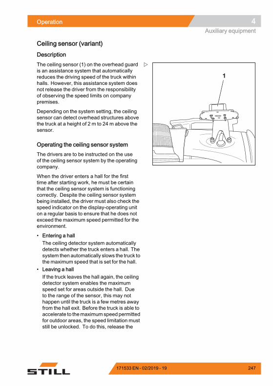
Operation 4Auxiliary equipment
Ceiling sensor (variant)
Description
1
The ceiling sensor (1) on the overhead guardis an assistance system that automaticallyreduces the driving speed of the truck withinhalls. However, this assistance system doesnot release the driver from the responsibilityof observing the speed limits on companypremises.
Depending on the system setting, the ceilingsensor can detect overhead structures abovethe truck at a height of 2 m to 24 m above thesensor.
Operating the ceiling sensor systemThe drivers are to be instructed on the useof the ceiling sensor system by the operatingcompany.
When the driver enters a hall for the firsttime after starting work, he must be certainthat the ceiling sensor system is functioningcorrectly. Despite the ceiling sensor systembeing installed, the driver must also check thespeed indicator on the display-operating uniton a regular basis to ensure that he does notexceed the maximum speed permitted for theenvironment.
• Entering a hallThe ceiling detector system automaticallydetects whether the truck enters a hall. Thesystem then automatically slows the truck tothemaximum speed that is set for the hall.
• Leaving a hallIf the truck leaves the hall again, the ceilingdetector system enables the maximumspeed set for areas outside the hall. Dueto the range of the sensor, this may nothappen until the truck is a fewmetres awayfrom the hall exit. Before the truck is able toaccelerate to themaximumspeedpermittedfor outdoor areas, the speed limitation muststill be unlocked. To do this, release the
171533 EN - 02/2019 - 19 247
4 OperationAuxiliary equipment
accelerator briefly and then operate theaccelerator again.
• Switching on the truck in a hallIf the truck is switched on inside a hall, theceiling detector system detects the hallceiling and reduces the driving speed to themaximum speed that is set for halls.
Possible limitations for object recognition• If the truck moves under larger overheadstructures outdoors, e.g. a pedestrianbridge, the ceiling sensor system mayinterpret this overhead structure to be a hallceiling and reduce the maximum speed.
• In rare cases, it may occur that the ceilingsensor system does not recognize a ceilingand does not then reduce the speed. Thiscan happen if the signals from the ceilingsensor are insufficiently reflected due to theceiling geometry; for example, if there arelarge window areas at a 45° angle.
In these cases, the sensitivity and the range ofthe ceiling sensor system must be adjusted.Formore information, refer to the next chapter.
Changing the sensor settingsThe ceiling sensor system is supplied bySTILL with the following factory settings:
Sensitivity: High
Ceiling height: 24 m
– Pull out the connecting cable from thesensor.
248 171533 EN - 02/2019 - 19
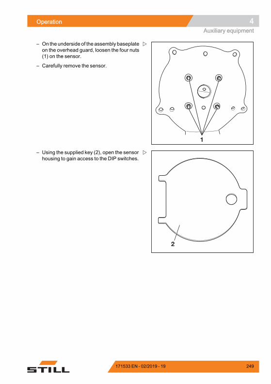
Operation 4Auxiliary equipment
1
– On the underside of the assembly baseplateon the overhead guard, loosen the four nuts(1) on the sensor.
– Carefully remove the sensor.
2
– Using the supplied key (2), open the sensorhousing to gain access to the DIP switches.
171533 EN - 02/2019 - 19 249
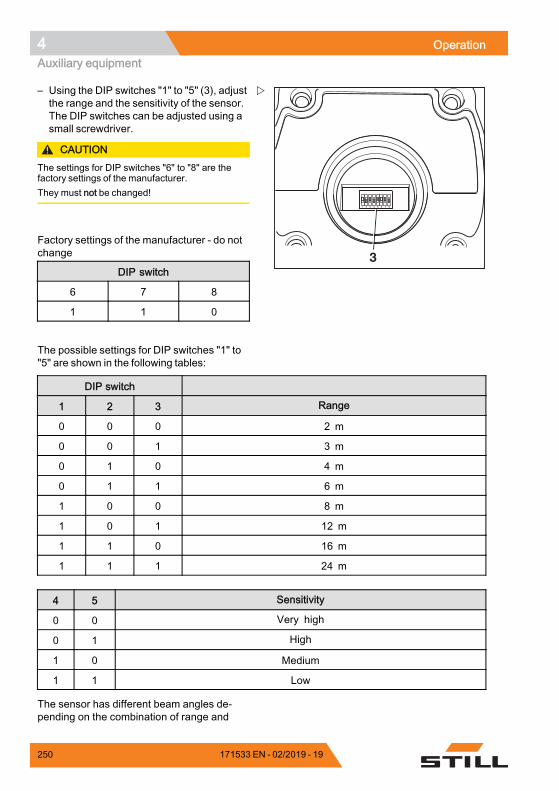
4 OperationAuxiliary equipment
1 2 3 4 5 6 7 8
3
– Using the DIP switches "1" to "5" (3), adjustthe range and the sensitivity of the sensor.The DIP switches can be adjusted using asmall screwdriver.
CAUTIONThe settings for DIP switches "6" to "8" are thefactory settings of the manufacturer.They must not be changed!
Factory settings of the manufacturer - do notchange
DIP switch
6 7 8
1 1 0
The possible settings for DIP switches "1" to"5" are shown in the following tables:
DIP switch
1 2 3 Range
0 0 0 2 m
0 0 1 3 m
0 1 0 4 m
0 1 1 6 m
1 0 0 8 m
1 0 1 12 m
1 1 0 16 m
1 1 1 24 m
4 5 Sensitivity
0 0 Very high
0 1 High
1 0 Medium
1 1 Low
The sensor has different beam angles de-pending on the combination of range and
250 171533 EN - 02/2019 - 19
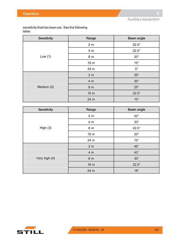
Operation 4Auxiliary equipment
sensitivity that has been set. See the followingtable:
Sensitivity Range Beam angle
2 m 22.5°
4 m 22.5°
8 m 20°
16 m 15°
Low (1)
24 m 5°
2 m 35°
4 m 30°
8 m 25°
16 m 22.5°
Medium (2)
24 m 10°
Sensitivity Range Beam angle
2 m 42°
4 m 33°
8 m 22.5°
16 m 20°
High (3)
24 m 15°
2 m 45°
4 m 43°
8 m 30°
16 m 22.5°
Very high (4)
24 m 18°
171533 EN - 02/2019 - 19 251
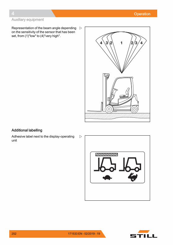
4 OperationAuxiliary equipment
2 3 41234
Representation of the beam angle dependingon the sensitivity of the sensor that has beenset, from (1)"low" to (4)"very high".
Additional labellingAdhesive label next to the display-operatingunit
252 171533 EN - 02/2019 - 19
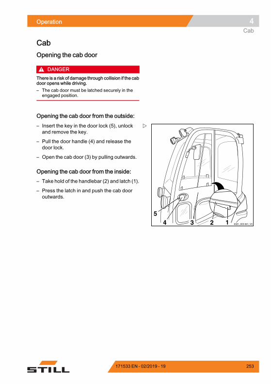
Operation 4Cab
CabOpening the cab door
DANGERThere is a risk of damage through collision if the cabdoor opens while driving.– The cab door must be latched securely in the
engaged position.
Opening the cab door from the outside:
6321_003-061_V345
2 13
– Insert the key in the door lock (5), unlockand remove the key.
– Pull the door handle (4) and release thedoor lock.
– Open the cab door (3) by pulling outwards.
Opening the cab door from the inside:– Take hold of the handlebar (2) and latch (1).
– Press the latch in and push the cab dooroutwards.
171533 EN - 02/2019 - 19 253
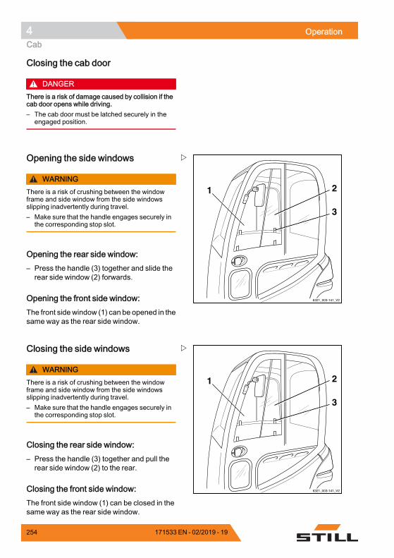
4 OperationCab
Closing the cab door
DANGERThere is a risk of damage caused by collision if thecab door opens while driving.– The cab door must be latched securely in the
engaged position.
6321_003-141_V2
3
1 2
Opening the side windows
WARNINGThere is a risk of crushing between the windowframe and side window from the side windowsslipping inadvertently during travel.– Make sure that the handle engages securely in
the corresponding stop slot.
Opening the rear side window:– Press the handle (3) together and slide therear side window (2) forwards.
Opening the front side window:The front side window (1) can be opened in thesame way as the rear side window.
6321_003-141_V2
3
1 2
Closing the side windows
WARNINGThere is a risk of crushing between the windowframe and side window from the side windowsslipping inadvertently during travel.– Make sure that the handle engages securely in
the corresponding stop slot.
Closing the rear side window:– Press the handle (3) together and pull therear side window (2) to the rear.
Closing the front side window:The front side window (1) can be closed in thesame way as the rear side window.
254 171533 EN - 02/2019 - 19
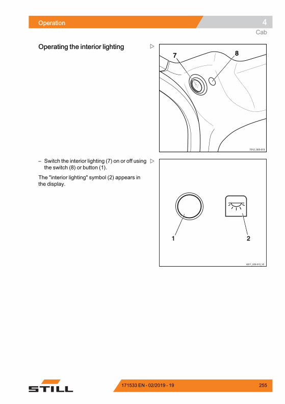
Operation 4Cab
7312_003-013
7 8Operating the interior lighting
6311_003-013_V2
21
– Switch the interior lighting (7) on or off usingthe switch (8) or button (1).
The "interior lighting" symbol (2) appears inthe display.
171533 EN - 02/2019 - 19 255
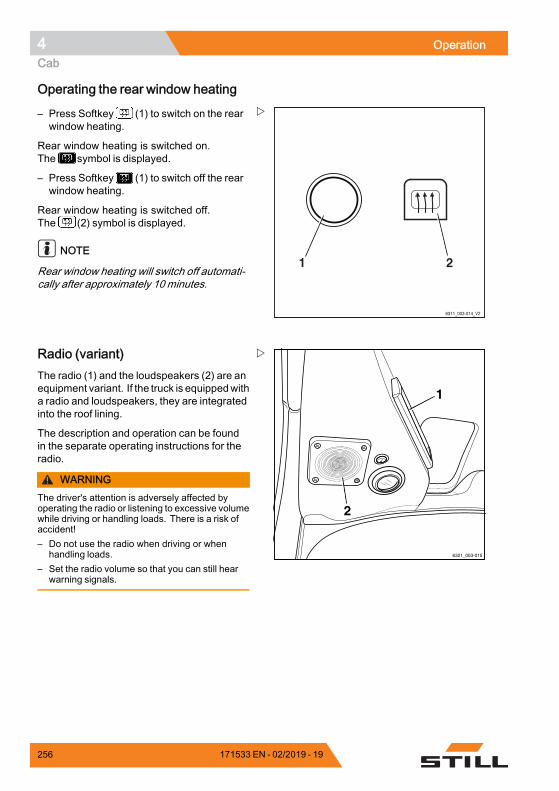
4 OperationCab
Operating the rear window heating
6311_003-014_V2
21
– Press Softkey (1) to switch on the rearwindow heating.
Rear window heating is switched on.The symbol is displayed.
– Press Softkey (1) to switch off the rearwindow heating.
Rear window heating is switched off.The (2) symbol is displayed.
NOTE
Rear window heating will switch off automati-cally after approximately 10 minutes.
6321_003-015
1
2
Radio (variant)The radio (1) and the loudspeakers (2) are anequipment variant. If the truck is equippedwitha radio and loudspeakers, they are integratedinto the roof lining.
The description and operation can be foundin the separate operating instructions for theradio.
WARNINGThe driver's attention is adversely affected byoperating the radio or listening to excessive volumewhile driving or handling loads. There is a risk ofaccident!– Do not use the radio when driving or when
handling loads.– Set the radio volume so that you can still hear
warning signals.
256 171533 EN - 02/2019 - 19
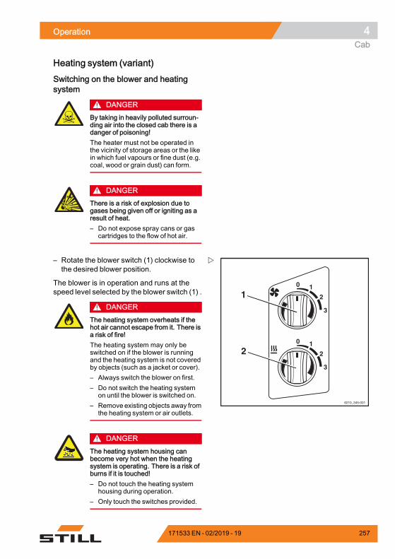
Operation 4Cab
Heating system (variant)
Switching on the blower and heatingsystem
DANGERBy taking in heavily polluted surroun-ding air into the closed cab there is adanger of poisoning!The heater must not be operated inthe vicinity of storage areas or the likein which fuel vapours or fine dust (e.g.coal, wood or grain dust) can form.
DANGERThere is a risk of explosion due togases being given off or igniting as aresult of heat.– Do not expose spray cans or gas
cartridges to the flow of hot air.
0 1
2
3
0 1
2
3
1
2
6210_345-001
– Rotate the blower switch (1) clockwise tothe desired blower position.
The blower is in operation and runs at thespeed level selected by the blower switch (1) .
DANGERThe heating system overheats if thehot air cannot escape from it. There isa risk of fire!The heating system may only beswitched on if the blower is runningand the heating system is not coveredby objects (such as a jacket or cover).– Always switch the blower on first.– Do not switch the heating system
on until the blower is switched on.– Remove existing objects away from
the heating system or air outlets.
DANGERThe heating system housing canbecome very hot when the heatingsystem is operating. There is a risk ofburns if it is touched!– Do not touch the heating system
housing during operation.– Only touch the switches provided.
171533 EN - 02/2019 - 19 257
4 OperationCab
– Rotate the heating level switch (2) clock-wise to the desired heating level.
The heating system is in operation. The airis heated up to the heating level set by theheating level switch (2).
Selecting blower settingsSetting blower to low:
– Set blower switch (1) to level 1.
Setting blower to medium:
– Set blower switch (1) to level 2.
Setting blower to high:
– Set blower switch (1) to level 3.
Setting heating levelsSet heating system to low (50%):
– Set heating level switch (2) to level 1.
Set heating system to medium (75%):
– Set heating level switch (2) to level 2.
Set heating system to high (100%):
– Set heating level switch (2) to level 3.
Turn off the heating system and blower
DANGERThe heating system overheats if thehot air cannot escape from it. There isa risk of fire!The blower may only be turned off ifthe heating system is turned off.– Always turn the heating system off
first.– Only turn the blower off when the
heating system is switched off.
– Rotate the heating level switch (2) anticlock-wise to heating level 0.
The heating system is out of order.
– Rotate the blower switch (1) anticlockwiseto blower position 0.
The blower is out of order.
258 171533 EN - 02/2019 - 19
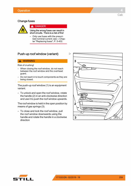
Operation 4Cab
Change fuses
DANGERUsing the wrong fuses can result inshort circuits. There is a risk of fire!– Only use fuses with the prescri-
bed nominal current; see ⇒ Chap-ter "Replacing fuses", P. 5-402.
6210_003-105_V2
1
2
3
3
Push-up roof window (variant)
WARNINGRisk of crushing!– When closing the roof window, do not reach
between the roof window and the overheadguard.
– Do not reach in to touch components as they arebeing closed.
The push-up roof window (1) is an equipmentvariant.
– To unlock and open the roof window, rotatethe handle (2) in an anti-clockwise directionand use it to push the roof window upwards.
The roof window is held in the open position bymeans of gas springs (3).
– To close and lock the roof window, pullthe roof window downwards using thehandle and rotate the handle in a clockwisedirection
171533 EN - 02/2019 - 19 259
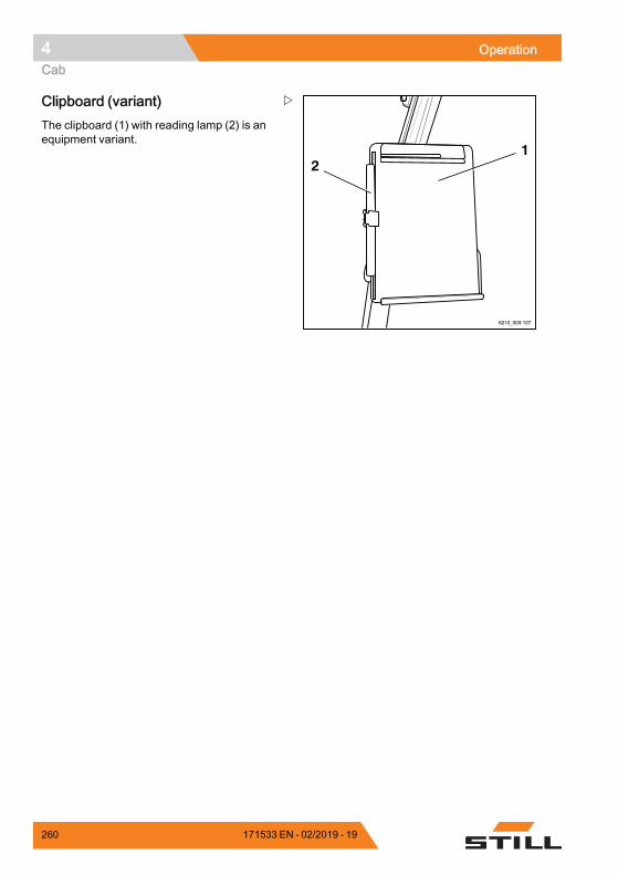
4 OperationCab
6210_003-107
21
Clipboard (variant)The clipboard (1) with reading lamp (2) is anequipment variant.
260 171533 EN - 02/2019 - 19
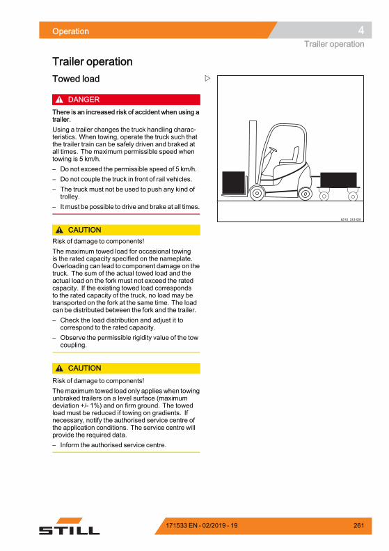
Operation 4Trailer operation
Trailer operation
6210_313-001
Towed load
DANGERThere is an increased risk of accident when using atrailer.Using a trailer changes the truck handling charac-teristics. When towing, operate the truck such thatthe trailer train can be safely driven and braked atall times. The maximum permissible speed whentowing is 5 km/h.– Do not exceed the permissible speed of 5 km/h.– Do not couple the truck in front of rail vehicles.– The truck must not be used to push any kind of
trolley.– It must be possible to drive and brake at all times.
CAUTIONRisk of damage to components!The maximum towed load for occasional towingis the rated capacity specified on the nameplate.Overloading can lead to component damage on thetruck. The sum of the actual towed load and theactual load on the fork must not exceed the ratedcapacity. If the existing towed load correspondsto the rated capacity of the truck, no load may betransported on the fork at the same time. The loadcan be distributed between the fork and the trailer.– Check the load distribution and adjust it to
correspond to the rated capacity.– Observe the permissible rigidity value of the tow
coupling.
CAUTIONRisk of damage to components!Themaximum towed load only applies when towingunbraked trailers on a level surface (maximumdeviation +/- 1%) and on firm ground. The towedload must be reduced if towing on gradients. Ifnecessary, notify the authorised service centre ofthe application conditions. The service centre willprovide the required data.– Inform the authorised service centre.
171533 EN - 02/2019 - 19 261
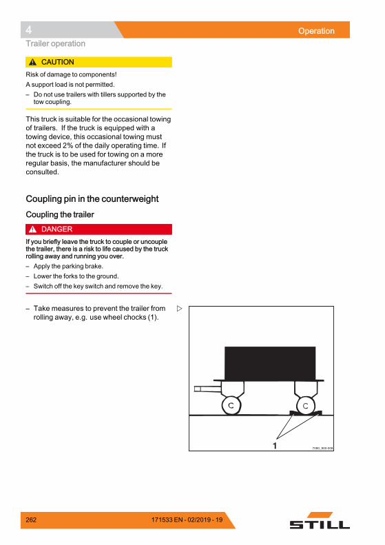
4 OperationTrailer operation
CAUTIONRisk of damage to components!A support load is not permitted.– Do not use trailers with tillers supported by the
tow coupling.
This truck is suitable for the occasional towingof trailers. If the truck is equipped with atowing device, this occasional towing mustnot exceed 2% of the daily operating time. Ifthe truck is to be used for towing on a moreregular basis, the manufacturer should beconsulted.
Coupling pin in the counterweight
Coupling the trailer
DANGERIf you briefly leave the truck to couple or uncouplethe trailer, there is a risk to life caused by the truckrolling away and running you over.– Apply the parking brake.– Lower the forks to the ground.– Switch off the key switch and remove the key.
1 7090_900-008
– Take measures to prevent the trailer fromrolling away, e.g. use wheel chocks (1).
262 171533 EN - 02/2019 - 19

Operation 4Trailer operation
6321_003-116
2
3
– Push the coupling pin (2) down, turn 90°and pull out.
– Adjust tiller height.
DANGERPeople can become trapped between the truck andtrailer.When hooking up, ensure that no one is betweenthe truck and trailer.
– Slowly move the truck back.
– Bymoving the truck back, introduce the tillerinto the recess (3) in the counterweight.
DANGERIf the coupling pin or securing bush are lost ordestroyed during towing, the trailer will work looseand become uncontrollable. This causes a risk ofaccident!– Use only original coupling pins that have been
checked carefully.– Ensure that the coupling pin is correctly inserted
and secured.
– Insert the coupling pin into the counter-weight, press downwards against the springpressure and turn 90° (the coupling pin islocked in this position).
– Remove any items used to prevent thetrailer from rolling away.
Uncoupling the trailer– Take measures to prevent the trailer fromrolling away, e.g. use wheel chocks.
171533 EN - 02/2019 - 19 263
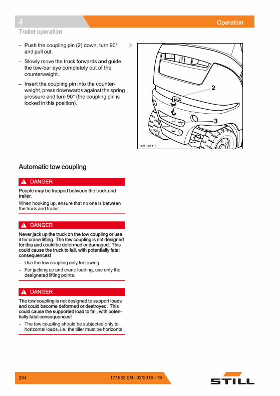
4 OperationTrailer operation
6321_003-116
2
3
– Push the coupling pin (2) down, turn 90°and pull out.
– Slowly move the truck forwards and guidethe tow-bar eye completely out of thecounterweight.
– Insert the coupling pin into the counter-weight, press downwards against the springpressure and turn 90° (the coupling pin islocked in this position).
Automatic tow coupling
DANGERPeople may be trapped between the truck andtrailer.When hooking up, ensure that no one is betweenthe truck and trailer.
DANGERNever jack up the truck on the tow coupling or useit for crane lifting. The tow coupling is not designedfor this and could be deformed or damaged. Thiscould cause the truck to fall, with potentially fatalconsequences!– Use the tow coupling only for towing.– For jacking up and crane loading, use only the
designated lifting points.
DANGERThe tow coupling is not designed to support loadsand could become deformed or destroyed. Thiscould cause the supported load to fall, with poten-tially fatal consequences!– The tow coupling should be subjected only to
horizontal loads, i.e. the tiller must be horizontal.
264 171533 EN - 02/2019 - 19
Operation 4Trailer operation
DANGERIf you briefly leave the truck to couple or uncouplethe trailer, there is a risk to life caused by the truckrolling away and running you over.– Apply the parking brake.– Lower the forks to the ground.– Switch off the key switch and remove the key.
WARNINGNever reach between the coupling pins and thetowing jaws. If the component moves suddenlythere is a risk of injury!– To release the coupling pin, actuate the corre-
sponding lever or use a suitable device (e.g.assembly lever).
– When not in use, close the automatic towcoupling.
WARNINGRisk of damage due to component collision.A truck with tow coupling needs more room formanoeuvring due to its overhang. The tow couplingcan damage the racking or the tow coupling itselfwhen manoeuvring. If there is a collision with thetow coupling, test the tow coupling for damagesuch as cracks. A damaged tow coupling must notbe used again.– Always manoeuvre carefully and with sufficient
room.– In the case of a collision, test the tow coupling for
damage.– Replace tow coupling if damaged, if necessary
contact the authorised service centre.
WARNINGRisk of damage to the tow bar eye or tiller!Due to the truck's rear wheel steering, the sideslewing angle of the tiller may not be adequate. Thecoupling or the tiller may be damaged! The tow bareye of the tiller must fit the tow coupling in terms ofshape and size.– Ensure that the tow bar eye and tiller fit correctly.– Avoid sharp cornering.– Exercise care when travelling and manoeuvring
in reverse.
171533 EN - 02/2019 - 19 265
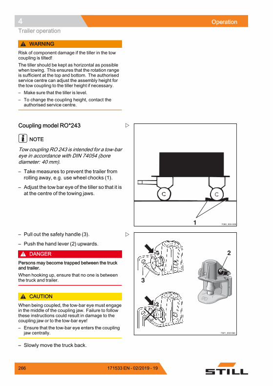
4 OperationTrailer operation
WARNINGRisk of component damage if the tiller in the towcoupling is tilted!The tiller should be kept as horizontal as possiblewhen towing. This ensures that the rotation rangeis sufficient at the top and bottom. The authorisedservice centre can adjust the assembly height forthe tow coupling to the tiller height if necessary.– Make sure that the tiller is level.– To change the coupling height, contact the
authorised service centre.
1 7090_900-008
Coupling model RO*243
NOTE
Tow coupling RO 243 is intended for a tow-bareye in accordance with DIN 74054 (borediameter: 40 mm).
– Take measures to prevent the trailer fromrolling away, e.g. use wheel chocks (1).
– Adjust the tow bar eye of the tiller so that it isat the centre of the towing jaws.
3
7321_003-064
2
– Pull out the safety handle (3).
– Push the hand lever (2) upwards.
DANGERPersons may become trapped between the truckand trailer.When hooking up, ensure that no one is betweenthe truck and trailer.
CAUTIONWhen being coupled, the tow-bar eye must engagein the middle of the coupling jaw. Failure to followthese instructions could result in damage to thecoupling jaw or to the tow-bar eye!– Ensure that the tow-bar eye enters the coupling
jaw centrally.
– Slowly move the truck back.
266 171533 EN - 02/2019 - 19
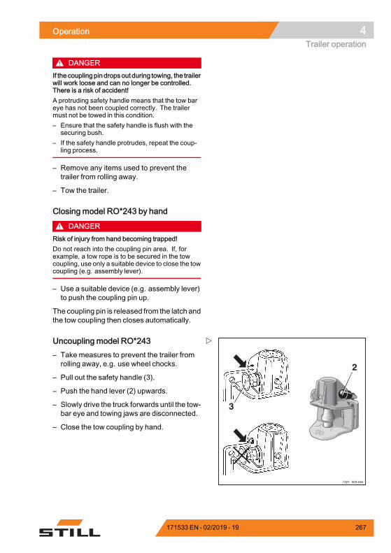
Operation 4Trailer operation
DANGERIf the coupling pin dropsout during towing, the trailerwill work loose and can no longer be controlled.There is a risk of accident!A protruding safety handle means that the tow bareye has not been coupled correctly. The trailermust not be towed in this condition.– Ensure that the safety handle is flush with the
securing bush.– If the safety handle protrudes, repeat the coup-
ling process.
– Remove any items used to prevent thetrailer from rolling away.
– Tow the trailer.
Closing model RO*243 by hand
DANGERRisk of injury from hand becoming trapped!Do not reach into the coupling pin area. If, forexample, a tow rope is to be secured in the towcoupling, use only a suitable device to close the towcoupling (e.g. assembly lever).
– Use a suitable device (e.g. assembly lever)to push the coupling pin up.
The coupling pin is released from the latch andthe tow coupling then closes automatically.
3
7321_003-064
2
Uncoupling model RO*243– Take measures to prevent the trailer fromrolling away, e.g. use wheel chocks.
– Pull out the safety handle (3).
– Push the hand lever (2) upwards.
– Slowly drive the truck forwards until the tow-bar eye and towing jaws are disconnected.
– Close the tow coupling by hand.
171533 EN - 02/2019 - 19 267
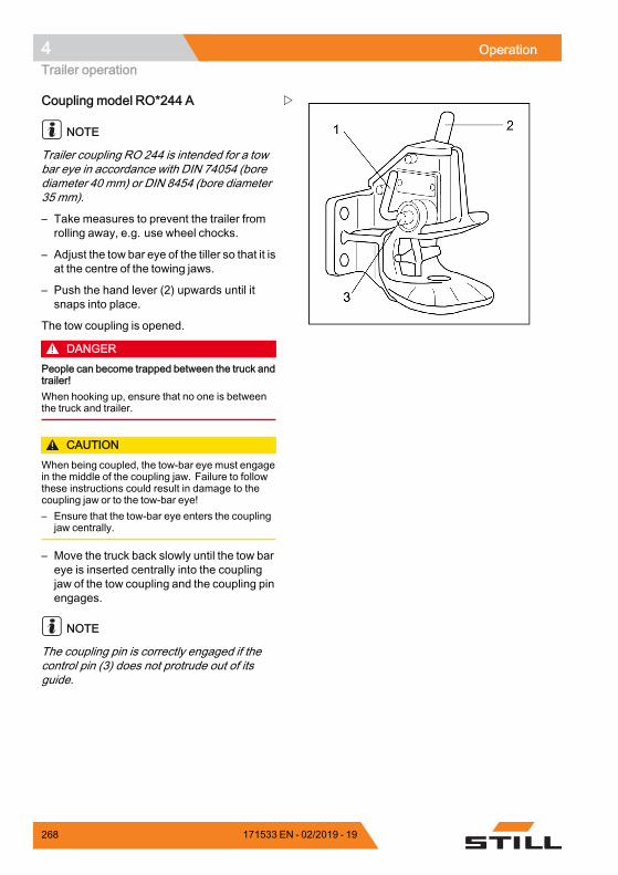
4 OperationTrailer operation
Coupling model RO*244 A
NOTE
Trailer coupling RO 244 is intended for a towbar eye in accordance with DIN 74054 (borediameter 40 mm) or DIN 8454 (bore diameter35 mm).
– Take measures to prevent the trailer fromrolling away, e.g. use wheel chocks.
– Adjust the tow bar eye of the tiller so that it isat the centre of the towing jaws.
– Push the hand lever (2) upwards until itsnaps into place.
The tow coupling is opened.
DANGERPeople can become trapped between the truck andtrailer!When hooking up, ensure that no one is betweenthe truck and trailer.
CAUTIONWhen being coupled, the tow-bar eye must engagein the middle of the coupling jaw. Failure to followthese instructions could result in damage to thecoupling jaw or to the tow-bar eye!– Ensure that the tow-bar eye enters the coupling
jaw centrally.
– Move the truck back slowly until the tow bareye is inserted centrally into the couplingjaw of the tow coupling and the coupling pinengages.
NOTE
The coupling pin is correctly engaged if thecontrol pin (3) does not protrude out of itsguide.
268 171533 EN - 02/2019 - 19
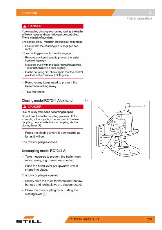
Operation 4Trailer operation
DANGERIf the coupling pin dropsout during towing, the trailerwill work loose and can no longer be controlled.There is a risk of accident!The control pin (3)must not protrude out of its guide.– Ensure that the coupling pin is engaged cor-
rectly.If the coupling pin is not correctly engaged:– Remove any items used to prevent the trailer
from rolling away.– Move the truck with the trailer forwards approx.
1 m and then move it back slightly.– On the coupling pin, check again that the control
pin does not protrude out of its guide.
– Remove any items used to prevent thetrailer from rolling away.
– Tow the trailer.
Closing model RO*244 A by hand
DANGERRisk of injury from hand becoming trapped!Do not reach into the coupling pin area. If, forexample, a tow rope is to be secured in the towcoupling, only actuate the tow coupling via theclosing lever (1).
– Press the closing lever (1) downwards asfar as it will go.
The tow coupling is closed.
Uncoupling model RO*244 A– Take measures to prevent the trailer fromrolling away, e.g. use wheel chocks.
– Push the hand lever (2) upwards until itsnaps into place.
The tow coupling is opened.
– Slowly drive the truck forwards until the tow-bar eye and towing jaws are disconnected.
– Close the tow coupling by actuating theclosing lever (1).
171533 EN - 02/2019 - 19 269
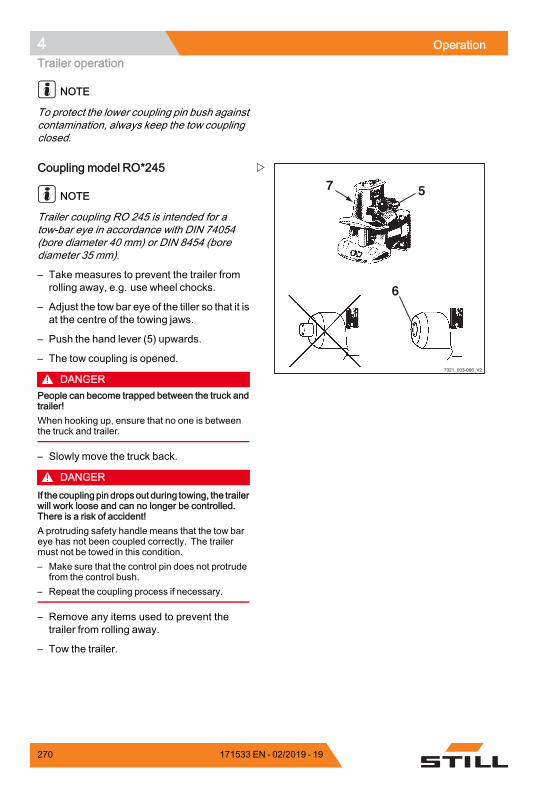
4 OperationTrailer operation
NOTE
To protect the lower coupling pin bush againstcontamination, always keep the tow couplingclosed.
7321_003-066_V2
57
6
Coupling model RO*245
NOTE
Trailer coupling RO 245 is intended for atow-bar eye in accordance with DIN 74054(bore diameter 40 mm) or DIN 8454 (borediameter 35 mm).
– Take measures to prevent the trailer fromrolling away, e.g. use wheel chocks.
– Adjust the tow bar eye of the tiller so that it isat the centre of the towing jaws.
– Push the hand lever (5) upwards.
– The tow coupling is opened.
DANGERPeople can become trapped between the truck andtrailer!When hooking up, ensure that no one is betweenthe truck and trailer.
– Slowly move the truck back.
DANGERIf thecoupling pin dropsout during towing, the trailerwill work loose and can no longer be controlled.There is a risk of accident!A protruding safety handle means that the tow bareye has not been coupled correctly. The trailermust not be towed in this condition.– Make sure that the control pin does not protrude
from the control bush.– Repeat the coupling process if necessary.
– Remove any items used to prevent thetrailer from rolling away.
– Tow the trailer.
270 171533 EN - 02/2019 - 19
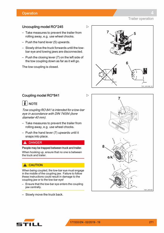
Operation 4Trailer operation
7321_003-066_V2
57
6
Uncoupling model RO*245– Take measures to prevent the trailer fromrolling away, e.g. use wheel chocks.
– Push the hand lever (5) upwards.
– Slowly drive the truck forwards until the tow-bar eye and towing jaws are disconnected.
– Push the closing lever (7) on the left side ofthe tow coupling down as far as it will go.
The tow coupling is closed.
7
8
7321_003-067
Coupling model RO*841
NOTE
Tow coupling RO 841 is intended for a tow-bareye in accordance with DIN 74054 (borediameter 40 mm).
– Take measures to prevent the trailer fromrolling away, e.g. use wheel chocks.
– Push the hand lever (7) upwards until itsnaps into place.
DANGERPeople may be trapped between truck and trailer.When hooking up, ensure that no one is betweenthe truck and trailer.
CAUTIONWhen being coupled, the tow-bar eye must engagein the middle of the coupling jaw. Failure to followthese instructions could result in damage to thecoupling jaw or to the tow-bar eye!– Ensure that the tow-bar eye enters the coupling
jaw centrally.
– Slowly move the truck back.
171533 EN - 02/2019 - 19 271
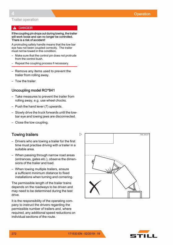
4 OperationTrailer operation
DANGERIf thecoupling pin dropsout during towing, the trailerwill work loose and can no longer be controlled.There is a risk of accident!A protruding safety handle means that the tow bareye has not been coupled correctly. The trailermust not be towed in this condition.– Make sure that the control pin does not protrude
from the control bush.– Repeat the coupling process if necessary.
– Remove any items used to prevent thetrailer from rolling away.
– Tow the trailer.
Uncoupling model RO*841– Take measures to prevent the trailer fromrolling away, e.g. use wheel chocks.
– Push the hand lever (7) upwards.
– Slowly drive the truck forwards until the tow-bar eye and towing jaws are disconnected.
– Close the tow coupling.
7090_900-011Towing trailers– Drivers who are towing a trailer for the firsttime must practise driving with a trailer in asuitable area.
– When passing through narrow road areas(entrances, gates etc.), observe the dimen-sions of the trailer and load.
– When towing multiple trailers, ensurea sufficient minimum distance to fixedinstallations when turning and cornering.
The permissible length of the trailer trainsdepends on the roadways to be driven andmay need to be determined during the testdrive.
It is the responsibility of the operating com-pany to instruct the drivers regarding thepermissible number of trailers and, whererequired, any additional speed reductions onindividual sections of the route.
272 171533 EN - 02/2019 - 19
Operation 4Trailer operation
NOTE
Please observe the definition of the followingresponsible persons: "operating company"and "driver".
171533 EN - 02/2019 - 19 273
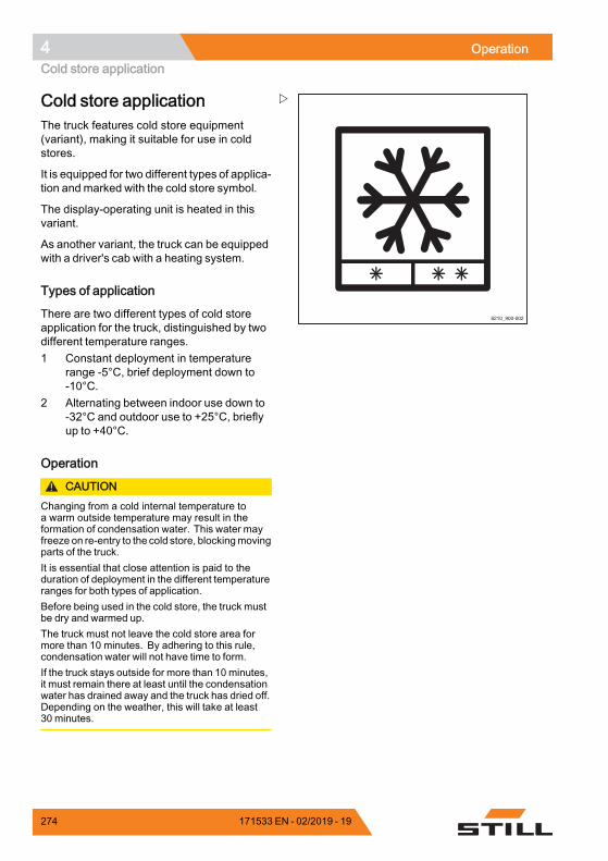
4 OperationCold store application
6210_900-002
Cold store applicationThe truck features cold store equipment(variant), making it suitable for use in coldstores.
It is equipped for two different types of applica-tion and marked with the cold store symbol.
The display-operating unit is heated in thisvariant.
As another variant, the truck can be equippedwith a driver's cab with a heating system.
Types of application
There are two different types of cold storeapplication for the truck, distinguished by twodifferent temperature ranges.1 Constant deployment in temperature
range -5°C, brief deployment down to-10°C.
2 Alternating between indoor use down to-32°C and outdoor use to +25°C, brieflyup to +40°C.
Operation
CAUTIONChanging from a cold internal temperature toa warm outside temperature may result in theformation of condensation water. This water mayfreeze on re-entry to the cold store, blockingmovingparts of the truck.It is essential that close attention is paid to theduration of deployment in the different temperatureranges for both types of application.Before being used in the cold store, the truck mustbe dry and warmed up.The truck must not leave the cold store area formore than 10 minutes. By adhering to this rule,condensation water will not have time to form.If the truck stays outside for more than 10 minutes,it must remain there at least until the condensationwater has drained away and the truck has dried off.Depending on the weather, this will take at least30 minutes.
274 171533 EN - 02/2019 - 19
Operation 4Cold store application
WARNINGRisk of injury!If condensation water freezes in the cold store, donot try to free parts that have become stuck withyour hands.
– To ensure operational safety, drive the truckfor approximately 5minutes and actuate thebrake several times.
– Actuate all hydraulic lifting functions severaltimes.
This warm-up phase is necessary to ensurethat the oil reaches the operating temperature.
– Always park the truck outside the cold store.
CAUTIONRisk of component damage!The lead-acid batteries must not be left in the coldstore overnight without power uptake or charging.
– Charge the battery outside the cold store.Operate the truck using a replacementbattery.
Using batteries in the cold storeTo compensate for the reduction in capacityat low temperatures, it is advisable to uselead-acid batteries with the maximum nominalcapacity in the respective battery dimensionsfor the truck series.
Electric trucks must not be parked in a coldarea for any longer than necessary. This alsoapplies to unused batteries. The chargingstation and the parking area for trucks andbatteries must be at normal room temperature(not below 10°C). Charging is extremely slowat low temperatures. At temperatures below10°C, the battery cannot be fully charged withthe usual charging parameters.
– Charge the battery fully before each shift.
– During the gassing phase, always top upwith distilled water.
To prevent the distilled water from freezing, itmust be mixed with the battery acid.
171533 EN - 02/2019 - 19 275

4 OperationCold store application
Water top-up systems must not be used attemperatures below 0°C, as this could causethe systems and the water present in the hoselines to freeze.
The battery voltage when discharged is thusgenerally lower at low temperatures. Thefinal discharged voltage is reached earlier,meaning the capacity of the battery is lower.
276 171533 EN - 02/2019 - 19
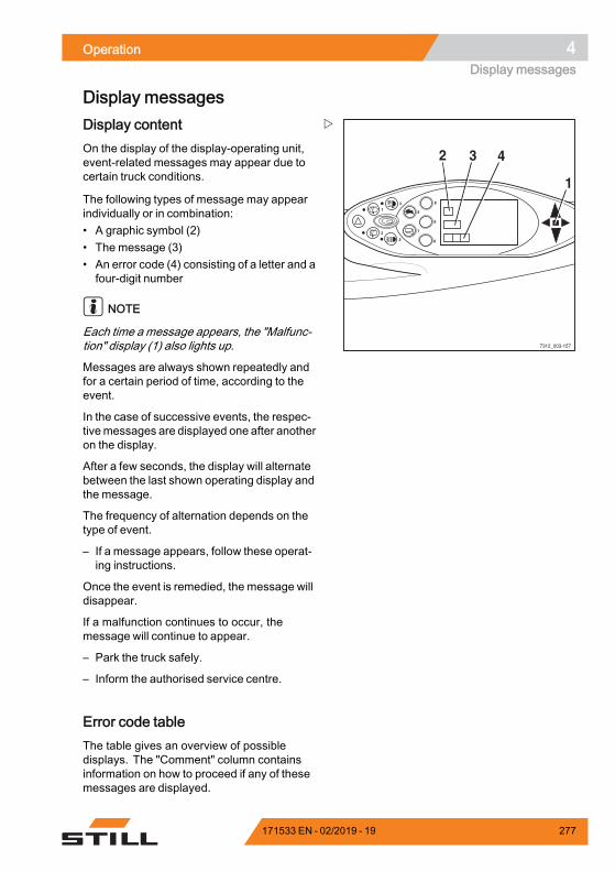
Operation 4Display messages
Display messages
8
9
0
6
7
4
2
1
3
5
7312_003-157
2 3 4
1
Display contentOn the display of the display-operating unit,event-related messages may appear due tocertain truck conditions.
The following types of message may appearindividually or in combination:• A graphic symbol (2)• The message (3)• An error code (4) consisting of a letter and afour-digit number
NOTE
Each time a message appears, the "Malfunc-tion" display (1) also lights up.
Messages are always shown repeatedly andfor a certain period of time, according to theevent.
In the case of successive events, the respec-tivemessages are displayed one after anotheron the display.
After a few seconds, the display will alternatebetween the last shown operating display andthe message.
The frequency of alternation depends on thetype of event.
– If a message appears, follow these operat-ing instructions.
Once the event is remedied, the message willdisappear.
If a malfunction continues to occur, themessage will continue to appear.
– Park the truck safely.
– Inform the authorised service centre.
Error code tableThe table gives an overview of possibledisplays. The "Comment" column containsinformation on how to proceed if any of thesemessages are displayed.
171533 EN - 02/2019 - 19 277
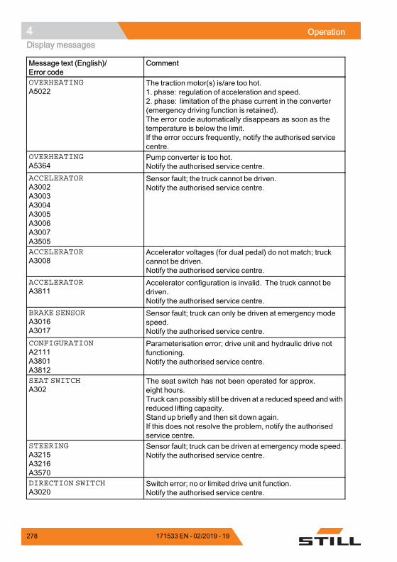
4 OperationDisplay messages
Message text (English)/Error code
Comment
OVERHEATINGA5022
The traction motor(s) is/are too hot.1. phase: regulation of acceleration and speed.2. phase: limitation of the phase current in the converter(emergency driving function is retained).The error code automatically disappears as soon as thetemperature is below the limit.If the error occurs frequently, notify the authorised servicecentre.
OVERHEATINGA5364
Pump converter is too hot.Notify the authorised service centre.
ACCELERATORA3002A3003A3004A3005A3006A3007A3505
Sensor fault; the truck cannot be driven.Notify the authorised service centre.
ACCELERATORA3008
Accelerator voltages (for dual pedal) do not match; truckcannot be driven.Notify the authorised service centre.
ACCELERATORA3811
Accelerator configuration is invalid. The truck cannot bedriven.Notify the authorised service centre.
BRAKE SENSORA3016A3017
Sensor fault; truck can only be driven at emergency modespeed.Notify the authorised service centre.
CONFIGURATIONA2111A3801A3812
Parameterisation error; drive unit and hydraulic drive notfunctioning.Notify the authorised service centre.
SEAT SWITCHA302
The seat switch has not been operated for approx.eight hours.Truck can possibly still be driven at a reduced speed andwithreduced lifting capacity.Stand up briefly and then sit down again.If this does not resolve the problem, notify the authorisedservice centre.
STEERINGA3215A3216A3570
Sensor fault; truck can be driven at emergency mode speed.Notify the authorised service centre.
DIRECTION SWITCHA3020
Switch error; no or limited drive unit function.Notify the authorised service centre.
278 171533 EN - 02/2019 - 19
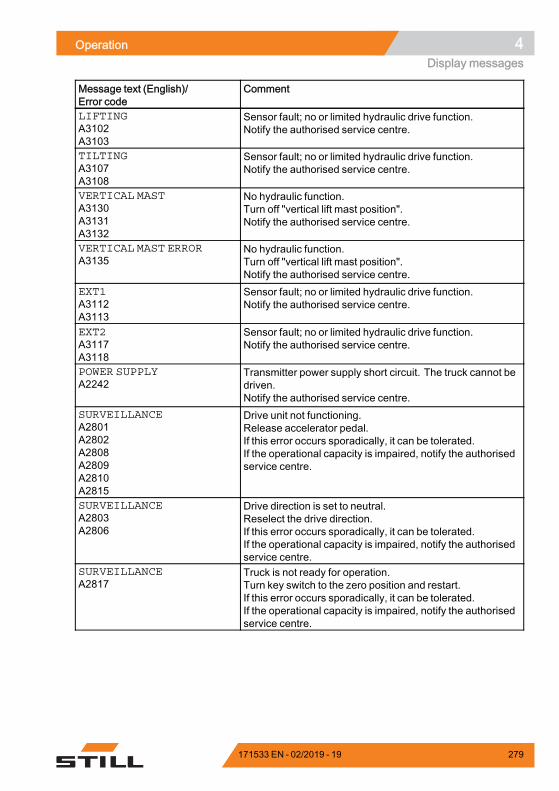
Operation 4Display messages
Message text (English)/Error code
Comment
LIFTINGA3102A3103
Sensor fault; no or limited hydraulic drive function.Notify the authorised service centre.
TILTINGA3107A3108
Sensor fault; no or limited hydraulic drive function.Notify the authorised service centre.
VERTICAL MASTA3130A3131A3132
No hydraulic function.Turn off "vertical lift mast position".Notify the authorised service centre.
VERTICAL MAST ERRORA3135
No hydraulic function.Turn off "vertical lift mast position".Notify the authorised service centre.
EXT1A3112A3113
Sensor fault; no or limited hydraulic drive function.Notify the authorised service centre.
EXT2A3117A3118
Sensor fault; no or limited hydraulic drive function.Notify the authorised service centre.
POWER SUPPLYA2242
Transmitter power supply short circuit. The truck cannot bedriven.Notify the authorised service centre.
SURVEILLANCEA2801A2802A2808A2809A2810A2815
Drive unit not functioning.Release accelerator pedal.If this error occurs sporadically, it can be tolerated.If the operational capacity is impaired, notify the authorisedservice centre.
SURVEILLANCEA2803A2806
Drive direction is set to neutral.Reselect the drive direction.If this error occurs sporadically, it can be tolerated.If the operational capacity is impaired, notify the authorisedservice centre.
SURVEILLANCEA2817
Truck is not ready for operation.Turn key switch to the zero position and restart.If this error occurs sporadically, it can be tolerated.If the operational capacity is impaired, notify the authorisedservice centre.
171533 EN - 02/2019 - 19 279

4 OperationDisplay messages
Message text (English)/Error code
Comment
SURVEILLANCEA2804A2805A2807A2811A2812A2813A2814A2816A2818
No or limited drive unit function.Notify the authorised service centre.
SURVEILLANCEA2295
No or limited function of drive unit and hydraulic drive.Notify the authorised service centre.
DRIVEA5031A5041A5046A5301A5331A5361
Temperature sensor fault.Notify the authorised service centre.
BATTERY CHANGERA5910
The support roller for the hydraulic battery carrier is notextended.Notify the authorised service centre.
BATTERY CHANGERA5920
Hydraulic pump of the hydraulic battery carrier is overheat-ing.Allow the truck to cool down for one hour.
BATTERY CHANGERA5930
Button errorNotify the authorised service centre.
BATTERY CHANGERA5931
Plausibility error from the potentiometer for the hydraulicbattery carrier.Notify the authorised service centre.
CONTROL UNITA3305
CIO not functioning.Notify the authorised service centre.
PARKING BRAKE OIL PRES-SUREA3043
The oil pressure in the parking brake is too low; the drive unitis locked.Notify the authorised service centre.
PARKING BRAKE OIL PRES-SUREA3049
The oil pressure in the parking brake is low; the truck onlymoves at emergency mode speed.Notify the authorised service centre.
LEVERA4601
The "lifting" operating device has been moved and held inplace for too long. The relevant hydraulic function is switchedoff.As soon as the operating device is released, the messagewill disappear and the hydraulic function will be availableagain. If required, the authorised service centre can disablemonitoring of the hydraulic functions.
280 171533 EN - 02/2019 - 19
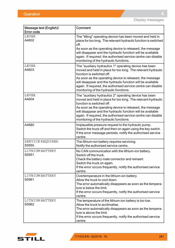
Operation 4Display messages
Message text (English)/Error code
Comment
LEVERA4602
The "tilting" operating device has been moved and held inplace for too long. The relevant hydraulic function is switchedoff.As soon as the operating device is released, the messagewill disappear and the hydraulic function will be availableagain. If required, the authorised service centre can disablemonitoring of the hydraulic functions.
LEVERA4603
The "auxiliary hydraulics 1" operating device has beenmoved and held in place for too long. The relevant hydraulicfunction is switched off.As soon as the operating device is released, the messagewill disappear and the hydraulic function will be availableagain. If required, the authorised service centre can disablemonitoring of the hydraulic functions.
LEVERA4604
The "auxiliary hydraulics 2" operating device has beenmoved and held in place for too long. The relevant hydraulicfunction is switched off.As soon as the operating device is released, the messagewill disappear and the hydraulic function will be availableagain. If required, the authorised service centre can disablemonitoring of the hydraulic functions.
A4680 Implausible pressure request to the hydraulic pump.Switch the truck off and then on again using the key switch.If the error message persists, notify the authorised servicecentre.
SERVICE REQUIREDS5950
The lithium-ion battery requires servicing.Notify the authorised service centre.
LITHIUM BATTERYS5951
No CAN communication with the lithium-ion battery.Switch off the truck.Check the battery male connector and reinsert.Switch the truck on again.If the error occurs frequently, notify the authorised servicecentre.
LITHIUM BATTERYS5961
Overtemperature in the lithium-ion battery.Allow the truck to cool down.The error automatically disappears as soon as the tempera-ture is below the limit.If the error occurs frequently, notify the authorised servicecentre.
LITHIUM BATTERYS5962
The temperature of the lithium-ion battery is too low.Allow the truck to acclimatise.The error automatically disappears as soon as the tempera-ture is above the limit.If the error occurs frequently, notify the authorised servicecentre.
171533 EN - 02/2019 - 19 281
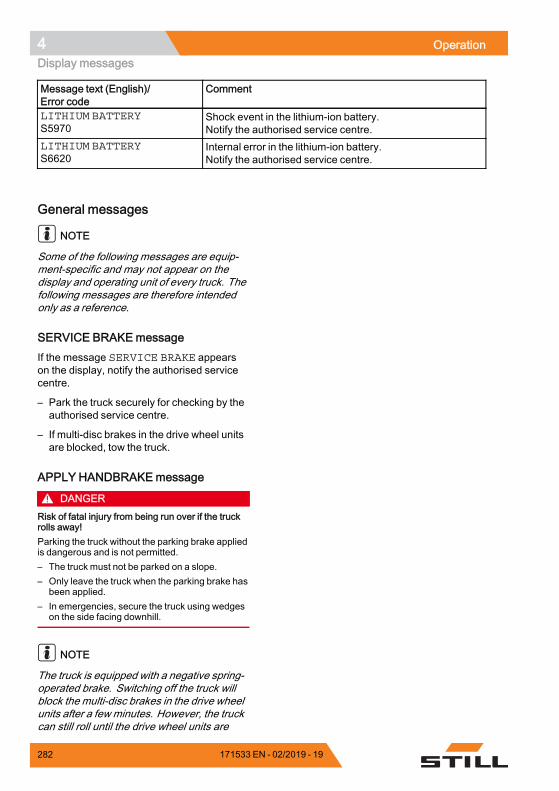
4 OperationDisplay messages
Message text (English)/Error code
Comment
LITHIUM BATTERYS5970
Shock event in the lithium-ion battery.Notify the authorised service centre.
LITHIUM BATTERYS6620
Internal error in the lithium-ion battery.Notify the authorised service centre.
.
General messages
NOTE
Some of the following messages are equip-ment-specific and may not appear on thedisplay and operating unit of every truck. Thefollowing messages are therefore intendedonly as a reference.
SERVICE BRAKEmessageIf the message SERVICE BRAKE appearson the display, notify the authorised servicecentre.
– Park the truck securely for checking by theauthorised service centre.
– If multi-disc brakes in the drive wheel unitsare blocked, tow the truck.
APPLY HANDBRAKEmessage
DANGERRisk of fatal injury from being run over if the truckrolls away!Parking the truck without the parking brake appliedis dangerous and is not permitted.– The truck must not be parked on a slope.– Only leave the truck when the parking brake has
been applied.– In emergencies, secure the truck using wedges
on the side facing downhill.
NOTE
The truck is equipped with a negative spring-operated brake. Switching off the truck willblock the multi-disc brakes in the drive wheelunits after a few minutes. However, the truckcan still roll until the drive wheel units are
282 171533 EN - 02/2019 - 19
Operation 4Display messages
blocked. For this reason, the parking brakemust always be applied before you leave thetruck!
If you park the truck without applying theparking brake and then vacate the driver'sseat, the APPLY HANDBRAKEmessage willappear in the display (variant). An optionalsignal tone sounds.
– Apply the parking brake.
The APPLY HANDBRAKEmessage disap-pears.
If the truck moves even though the parkingbrake is applied:
– Drive the truck onto level ground and park itsafely. Secure it with wedges if necessary.
– Notify the authorised service centre.
BRAKE SENSORmessageIf the BRAKE SENSORmessage appears inthe display, themaximum driving speedwill bereduced. The brake sensor in the brake pedalmust be checked.
– Notify the authorised service centre.
CODE DENIEDmessageIf the message CODE DENIED appears onthe display, the driver PIN has been enteredincorrectly three times. The input is thenlocked for five minutes before another attemptcan be made.
– Enter the driver PINagain after fiveminutes.
ACCELERATORmessageIf the ACCELERATORmessage appears onthe display, the truck will remain stationary.The accelerator must be checked.
– Notify the authorised service centre.
SWITCHOFF TRUCK?messageIf the message SWITCH OFF THE TRUCK?appears on the display, the switching-off of thetruck is verified.
171533 EN - 02/2019 - 19 283
4 OperationDisplay messages
– Press the corresponding softkey on thedisplay and operating unit to switch off thetruck or cancel the operation.
PARKING BRAKE ACTIVEmessageIf the electric parking brake is applied, thePARKING BRAKE ACTIVEmessage ap-pears on the display for 5 seconds.
– Release the parking brake to enable drivingmode.
RELEASE PARKING BRAKEmessageIf the message RELEASE PARKING BRAKEappears on the display, driving mode cannotbe enabled until the parking brake has beenreleased by pressing the button.
– Release the parking brake by pressing thebutton.
PARKING BRAKE: APPLY HAND-BRAKE! messageIf the message PARKING BRAKE: APPLYHANDBRAKE! appears on the display, theelectric parking brake is faulty.
– Release the parking brake by pressing thebutton.
LOWER FORKSmessage
DANGERThere is a risk of fatal injury from a falling load orparts of the truck being lowered!Parking the truck with the load lifted is dangerousand is not permitted under any circumstances! Theincreased safety provided by this function must notbe misused in order to take safety risks.– Lower the load fully before leaving the truck.
284 171533 EN - 02/2019 - 19
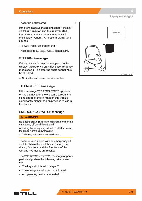
Operation 4Display messages
7312_003-071_en_V2
The fork is not lowered.
If the fork is above the height sensor, the keyswitch is turned off and the seat vacated,the LOWER FORKS message appears inthe display (variant). An optional signal tonesounds.
– Lower the fork to the ground.
The message LOWER FORKS disappears.
STEERINGmessageIf the STEERINGmessage appears in thedisplay, the truck will only move at emergencymode speed. The steering angle sensor mustbe checked.
– Notify the authorised service centre.
TILTING SPEEDmessageIf the message TILTING SPEED appearson the display after the welcome screen, thetilting speed of the lift mast on this truck issignificantly higher than on previous trucks inthis family.
EMERGENCY SWITCHmessage
WARNINGNoelectric braking assistance is available when theemergency off switch is actuated!Actuating the emergency off switch will disconnectthe drives from the power supply.– To brake, actuate the service brake.
The truck is equipped with an emergency offswitch. When this switch is actuated, thedriving functions and the functions of theworking hydraulics are blocked.
TheEMERGENCYSWITCHmessageappearsperiodically when the following criteria aremet:• The key switch is set to stage "I"• The emergency off switch is actuated• An operating device is actuated
171533 EN - 02/2019 - 19 285
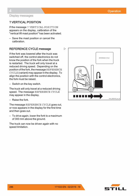
4 OperationDisplay messages
? VERTICAL POSITIONIf the message ? VERTICAL POSITIONappears on the display, calibration of the"vertical lift mast position" has been activated.
– Save the mast position or cancel thecalibration.
7312_003-072_en_V3
REFERENCE CYCLEmessageIf the fork was lowered after the truck wasswitched off, the control electronics do notknow the position of the fork when the truckis restarted. The truck will only travel at areduced driving speed. Depending on thepositionof the fork, themessageREFERENCECYCLE (variant)may appear in the display. Toalign the position with the control electronics,the fork must be raised.
– Switch on the key switch.
The truck will only travel at a reduced drivingspeed. The message REFERENCE CYCLEmay appear in the display.
– Raise the fork.
The message REFERENCE CYCLE goes out,or now appears in the display for the first timeand then goes out.
– To drive again, lower the fork to a maximumof 300 mm above the ground.
The truck can now be driven again with nospeed limitation.
286 171533 EN - 02/2019 - 19
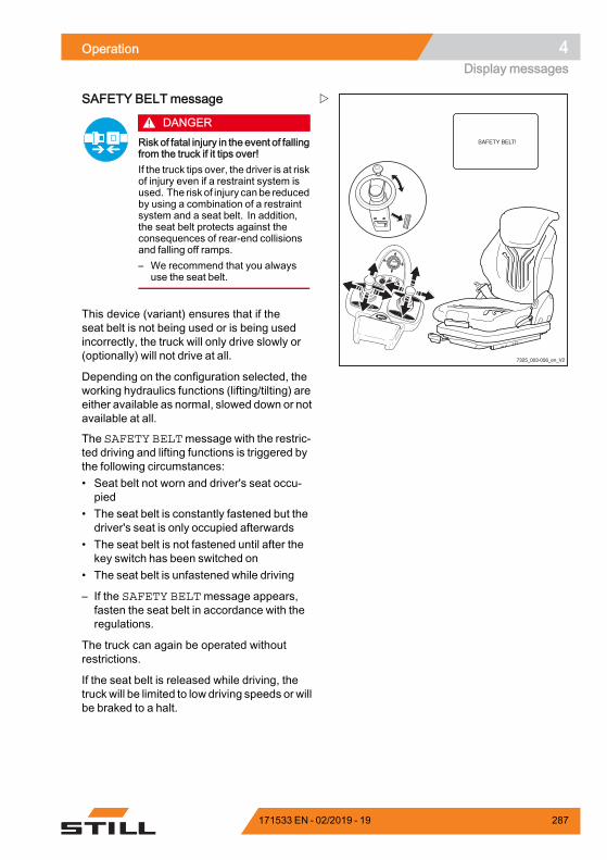
Operation 4Display messages
7325_003-056_en_V2
F1 F2
SAFETY BELTmessage
DANGERRisk of fatal injury in the event of fallingfrom the truck if it tips over!If the truck tips over, the driver is at riskof injury even if a restraint system isused. The risk of injury canbe reducedby using a combination of a restraintsystem and a seat belt. In addition,the seat belt protects against theconsequences of rear-end collisionsand falling off ramps.– We recommend that you always
use the seat belt.
This device (variant) ensures that if theseat belt is not being used or is being usedincorrectly, the truck will only drive slowly or(optionally) will not drive at all.
Depending on the configuration selected, theworking hydraulics functions (lifting/tilting) areeither available as normal, slowed down or notavailable at all.
The SAFETY BELTmessage with the restric-ted driving and lifting functions is triggered bythe following circumstances:• Seat belt not worn and driver's seat occu-pied
• The seat belt is constantly fastened but thedriver's seat is only occupied afterwards
• The seat belt is not fastened until after thekey switch has been switched on
• The seat belt is unfastened while driving
– If the SAFETY BELTmessage appears,fasten the seat belt in accordance with theregulations.
The truck can again be operated withoutrestrictions.
If the seat belt is released while driving, thetruck will be limited to low driving speeds or willbe braked to a halt.
171533 EN - 02/2019 - 19 287
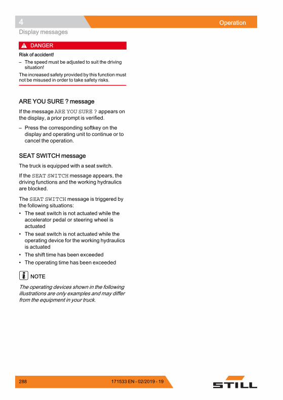
4 OperationDisplay messages
DANGERRisk of accident!– The speed must be adjusted to suit the driving
situation!The increased safety provided by this functionmustnot be misused in order to take safety risks.
ARE YOU SURE ?messageIf the message ARE YOU SURE ? appears onthe display, a prior prompt is verified.
– Press the corresponding softkey on thedisplay and operating unit to continue or tocancel the operation.
SEAT SWITCHmessageThe truck is equipped with a seat switch.
If the SEAT SWITCHmessage appears, thedriving functions and the working hydraulicsare blocked.
The SEAT SWITCHmessage is triggered bythe following situations:• The seat switch is not actuated while theaccelerator pedal or steering wheel isactuated
• The seat switch is not actuated while theoperating device for the working hydraulicsis actuated
• The shift time has been exceeded• The operating time has been exceeded
NOTE
The operating devices shown in the followingillustrations are only examples and may differfrom the equipment in your truck.
288 171533 EN - 02/2019 - 19
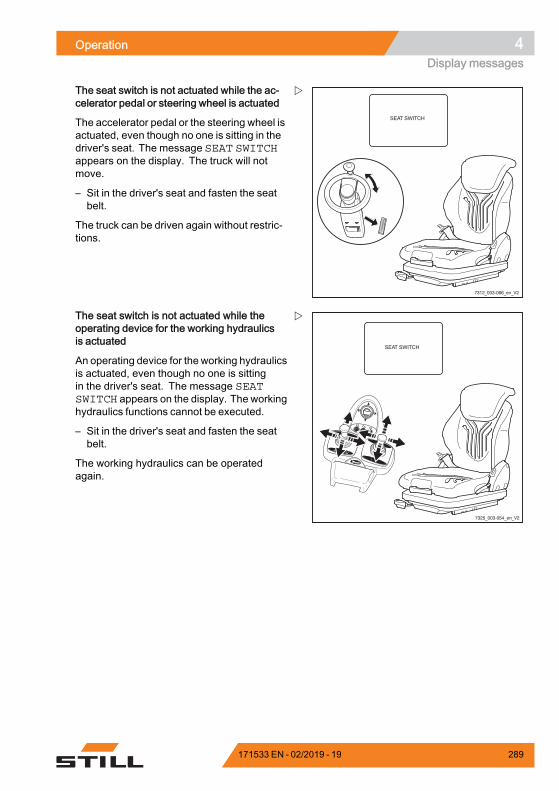
Operation 4Display messages
7312_003-066_en_V2
The seat switch is not actuated while the ac-celerator pedal or steering wheel is actuated
The accelerator pedal or the steering wheel isactuated, even though no one is sitting in thedriver's seat. The message SEAT SWITCHappears on the display. The truck will notmove.
– Sit in the driver's seat and fasten the seatbelt.
The truck can be driven again without restric-tions.
7325_003-054_en_V2
F1 F2
The seat switch is not actuated while theoperating device for the working hydraulicsis actuated
An operating device for the working hydraulicsis actuated, even though no one is sittingin the driver's seat. The message SEATSWITCH appears on the display. The workinghydraulics functions cannot be executed.
– Sit in the driver's seat and fasten the seatbelt.
The working hydraulics can be operatedagain.
171533 EN - 02/2019 - 19 289
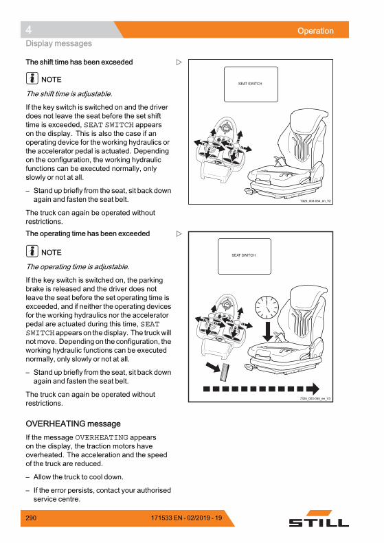
4 OperationDisplay messages
7325_003-054_en_V2
F1 F2
The shift time has been exceeded
NOTE
The shift time is adjustable.
If the key switch is switched on and the driverdoes not leave the seat before the set shifttime is exceeded, SEAT SWITCH appearson the display. This is also the case if anoperating device for the working hydraulics orthe accelerator pedal is actuated. Dependingon the configuration, the working hydraulicfunctions can be executed normally, onlyslowly or not at all.
– Stand up briefly from the seat, sit back downagain and fasten the seat belt.
The truck can again be operated withoutrestrictions.
7325_003-055_en_V3
F1 F2
The operating time has been exceeded
NOTE
The operating time is adjustable.
If the key switch is switched on, the parkingbrake is released and the driver does notleave the seat before the set operating time isexceeded, and if neither the operating devicesfor the working hydraulics nor the acceleratorpedal are actuated during this time, SEATSWITCHappears on the display. The truckwillnotmove. Depending on the configuration, theworking hydraulic functions can be executednormally, only slowly or not at all.
– Stand up briefly from the seat, sit back downagain and fasten the seat belt.
The truck can again be operated withoutrestrictions.
OVERHEATINGmessageIf the message OVERHEATING appearson the display, the traction motors haveoverheated. The acceleration and the speedof the truck are reduced.
– Allow the truck to cool down.
– If the error persists, contact your authorisedservice centre.
290 171533 EN - 02/2019 - 19
Operation 4Display messages
SURVEILLANCEmessageIf the SURVEILLANCE message appearsin the display, there is a fault in the processmonitoring.
This shuts off the drive unit.
– Switch the key switch to the "0" position andthen back to the "I" position.
– Start the engine.
– Release accelerator pedal.
– Select the drive direction again.
NOTE
If this error occurs sporadically, it can be tole-rated. If the operational capacity is impaired,notify your authorised service centre.
NOT VALID messageIf the message NOT VALID appears on thedisplay, an incorrect driver PIN has beenentered when entering the access code.
– Once the message goes out, enter thedriver PIN again.
Drive-specific messages
Message ! PARKING BRAKE OILPRESSUREIf the followingmessageappears in the displaywhen the accelerator pedal is actuated:! PARKING BRAKE OIL PRESSURE, theservice brake of the truck is not yet ready foruse.
The driving speed is limited to 5 km/h.
When the service brake is ready for operation,themessagedisappears. The speed limitationis cancelled.
MOT/GEN.-TEMP. messageIf the MOT/GEN.-TEMP.message appears,the traction motor or the generator is over-heated or a cable is broken.
171533 EN - 02/2019 - 19 291
4 OperationDisplay messages
– Interrupt work and allow the truck to cooldown. Do not switch off the key switch.
NOTE
If the operational capacity is impaired, notifyyour authorised service centre.
OVERHEATINGmessageIf the message OVERHEATING appearsin the display, the traction motors haveoverheated. The acceleration and the speedof the truck are reduced.
– Allow the truck to cool down.
– If the error persists, contact your authorisedservice centre.
CLOSE THE DOORmessageIf the message CLOSE THE DOOR (variant)appears in the display, the battery door is notshut correctly. The truck will not move.
– Close the battery door.
LEVERmessageIf an operating device is actuated continuouslyfor a long period, the Lever message isdisplayed with the error code A4601…4604.If you continue to move the operating device,the affected hydraulic function is switchedoff. The message disappears as soon as theoperating device is released. The hydraulicfunction is available again.
– Release the operating device.
LIFT HEIGHTmessageSpeed limitation with a raised load (variant)
This function makes sure that the truck canonly move slowly when a load is lifted.
292 171533 EN - 02/2019 - 19
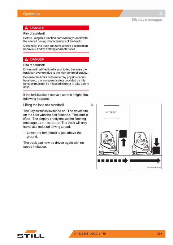
Operation 4Display messages
DANGERRisk of accident!Before using this function, familiarise yourself withthe altered driving characteristics of the truck!Optionally, the truck can have altered accelerationbehaviour and/or braking characteristics.
DANGERRisk of accident!Driving with a lifted load is prohibited because thetruck can overturn due to the high centre of gravity.Because the limits determined by physics cannotbe altered, the increased safety provided by thisfunction must not bemisused in order to take safetyrisks.
If the fork is raised above a certain height, thefollowing happens:
6210_003-054-en_V3
Lifting the load at a standstill
The key switch is switched on. The driver sitson the seat with the belt fastened. The load islifted. The display briefly shows the flashingmessage LIFT HEIGHT. The truck will onlytravel at a reduced driving speed.
– Lower the fork (load) to just above theground.
The truck can now be driven again with nospeed limitation.
171533 EN - 02/2019 - 19 293
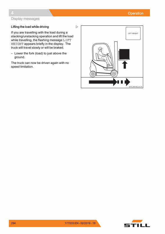
4 OperationDisplay messages
6210_003-055_en_V3
Lifting the load while driving
If you are travelling with the load during astacking/unstacking operation and lift the loadwhile travelling, the flashing message LIFTHEIGHT appears briefly in the display. Thetruck will travel slowly or will be braked.
– Lower the fork (load) to just above theground.
The truck can now be driven again with nospeed limitation.
294 171533 EN - 02/2019 - 19
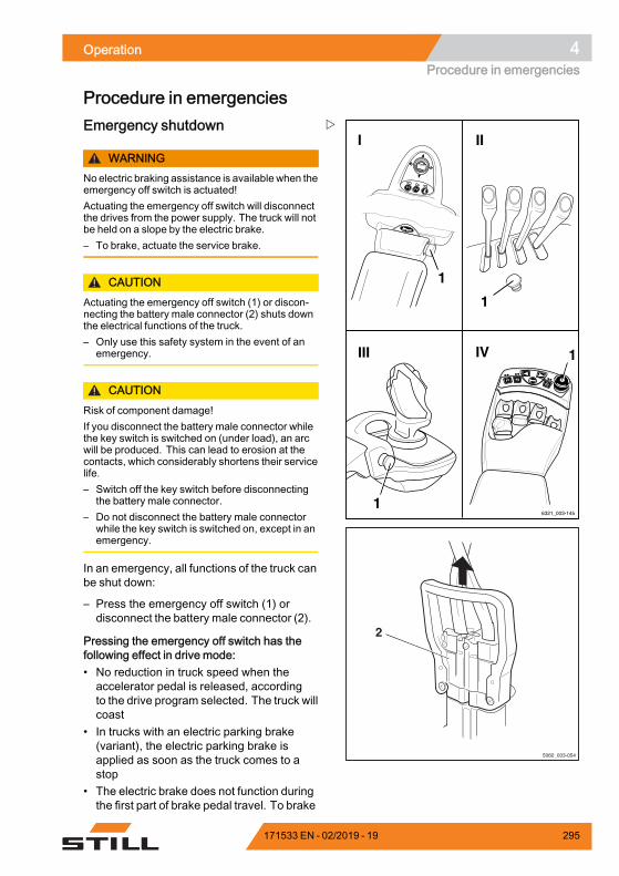
Operation 4Procedure in emergencies
Procedure in emergencies
6321_003-145
F1F1 F2F2
1
IV
I
III
II
F1 F2
1
1
1
2
5060_003-054
Emergency shutdown
WARNINGNoelectric braking assistance is available when theemergency off switch is actuated!Actuating the emergency off switch will disconnectthe drives from the power supply. The truck will notbe held on a slope by the electric brake.– To brake, actuate the service brake.
CAUTIONActuating the emergency off switch (1) or discon-necting the battery male connector (2) shuts downthe electrical functions of the truck.– Only use this safety system in the event of an
emergency.
CAUTIONRisk of component damage!If you disconnect the battery male connector whilethe key switch is switched on (under load), an arcwill be produced. This can lead to erosion at thecontacts, which considerably shortens their servicelife.– Switch off the key switch before disconnecting
the battery male connector.– Do not disconnect the battery male connector
while the key switch is switched on, except in anemergency.
In an emergency, all functions of the truck canbe shut down:
– Press the emergency off switch (1) ordisconnect the battery male connector (2).
Pressing the emergency off switch has thefollowing effect in drive mode:• No reduction in truck speed when theaccelerator pedal is released, accordingto the drive program selected. The truck willcoast
• In trucks with an electric parking brake(variant), the electric parking brake isapplied as soon as the truck comes to astop
• The electric brake does not function duringthe first part of brake pedal travel. To brake
171533 EN - 02/2019 - 19 295
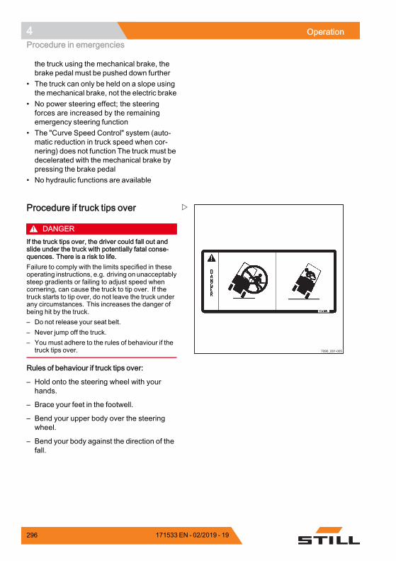
4 OperationProcedure in emergencies
the truck using the mechanical brake, thebrake pedal must be pushed down further
• The truck can only be held on a slope usingthemechanical brake, not the electric brake
• No power steering effect; the steeringforces are increased by the remainingemergency steering function
• The "Curve Speed Control" system (auto-matic reduction in truck speed when cor-nering) does not function The truck must bedecelerated with the mechanical brake bypressing the brake pedal
• No hydraulic functions are available
7090_001-005
Procedure if truck tips over
DANGERIf the truck tips over, the driver could fall out andslide under the truck with potentially fatal conse-quences. There is a risk to life.Failure to comply with the limits specified in theseoperating instructions, e.g. driving on unacceptablysteep gradients or failing to adjust speed whencornering, can cause the truck to tip over. If thetruck starts to tip over, do not leave the truck underany circumstances. This increases the danger ofbeing hit by the truck.– Do not release your seat belt.– Never jump off the truck.– You must adhere to the rules of behaviour if the
truck tips over.
Rules of behaviour if truck tips over:
– Hold onto the steering wheel with yourhands.
– Brace your feet in the footwell.
– Bend your upper body over the steeringwheel.
– Bend your body against the direction of thefall.
296 171533 EN - 02/2019 - 19
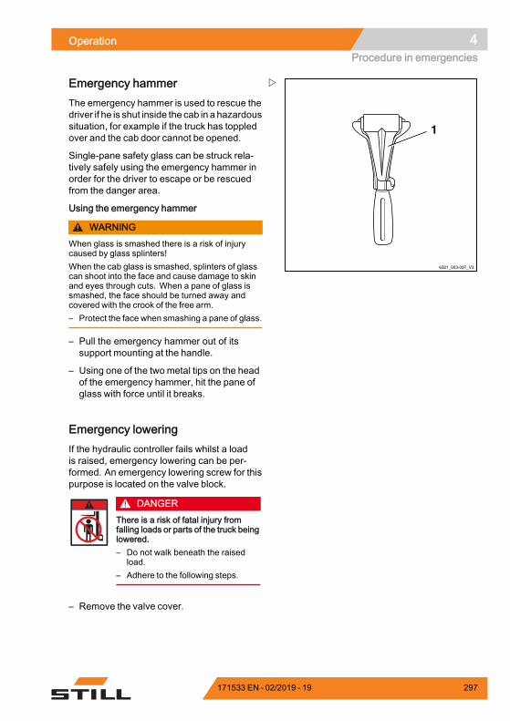
Operation 4Procedure in emergencies
6321_003-097_V3
1
Emergency hammerThe emergency hammer is used to rescue thedriver if he is shut inside the cab in a hazardoussituation, for example if the truck has toppledover and the cab door cannot be opened.
Single-pane safety glass can be struck rela-tively safely using the emergency hammer inorder for the driver to escape or be rescuedfrom the danger area.
Using the emergency hammer
WARNINGWhen glass is smashed there is a risk of injurycaused by glass splinters!When the cab glass is smashed, splinters of glasscan shoot into the face and cause damage to skinand eyes through cuts. When a pane of glass issmashed, the face should be turned away andcovered with the crook of the free arm.– Protect the face when smashing a pane of glass.
– Pull the emergency hammer out of itssupport mounting at the handle.
– Using one of the two metal tips on the headof the emergency hammer, hit the pane ofglass with force until it breaks.
Emergency loweringIf the hydraulic controller fails whilst a loadis raised, emergency lowering can be per-formed. An emergency lowering screw for thispurpose is located on the valve block.
DANGERThere is a risk of fatal injury fromfalling loads or parts of the truck beinglowered.– Do not walk beneath the raised
load.– Adhere to the following steps.
– Remove the valve cover.
171533 EN - 02/2019 - 19 297
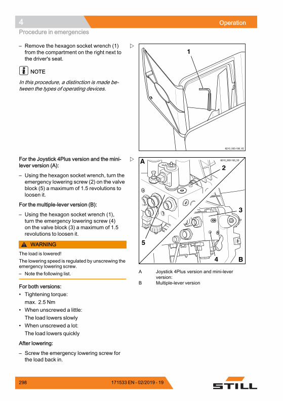
4 OperationProcedure in emergencies
6210_003-108_V2
1– Remove the hexagon socket wrench (1)from the compartment on the right next tothe driver's seat.
NOTE
In this procedure, a distinction is made be-tween the types of operating devices.
6210_003-100_V2
2
4
3
5
A
B
A Joystick 4Plus version and mini-leverversion:
B Multiple-lever version
For the Joystick 4Plus version and the mini-lever version (A):
– Using the hexagon socket wrench, turn theemergency lowering screw (2) on the valveblock (5) a maximum of 1.5 revolutions toloosen it.
For the multiple-lever version (B):
– Using the hexagon socket wrench (1),turn the emergency lowering screw (4)on the valve block (3) a maximum of 1.5revolutions to loosen it.
WARNINGThe load is lowered!The lowering speed is regulated by unscrewing theemergency lowering screw.– Note the following list.
For both versions:• Tightening torque:max. 2.5 Nm
• When unscrewed a little:The load lowers slowly
• When unscrewed a lot:The load lowers quickly
After lowering:
– Screw the emergency lowering screw forthe load back in.
298 171533 EN - 02/2019 - 19
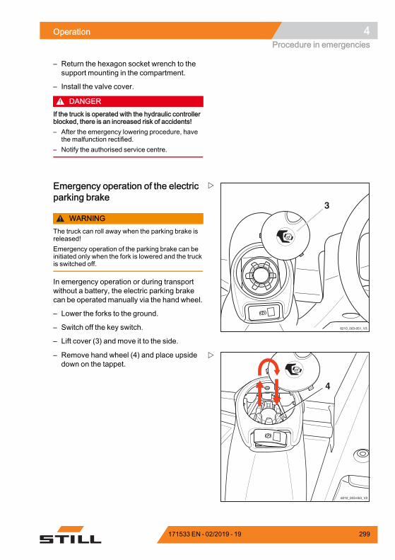
Operation 4Procedure in emergencies
– Return the hexagon socket wrench to thesupport mounting in the compartment.
– Install the valve cover.
DANGERIf the truck is operated with the hydraulic controllerblocked, there is an increased risk of accidents!– After the emergency lowering procedure, have
the malfunction rectified.– Notify the authorised service centre.
3
6210_003-051_V3
Emergency operation of the electricparking brake
WARNINGThe truck can roll away when the parking brake isreleased!Emergency operation of the parking brake can beinitiated only when the fork is lowered and the truckis switched off.
In emergency operation or during transportwithout a battery, the electric parking brakecan be operatedmanually via the hand wheel.
– Lower the forks to the ground.
– Switch off the key switch.
– Lift cover (3) and move it to the side.
6210_003-053_V2
4
– Remove hand wheel (4) and place upsidedown on the tappet.
171533 EN - 02/2019 - 19 299
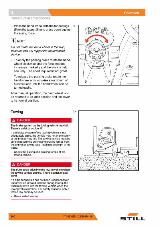
4 OperationProcedure in emergencies
656210_003-052_V3
5551
4391
001
1.2.
– Place the hand wheel with the tappet lugs(5) on the tappet (6) and press down againstthe spring force.
NOTE
Do not rotate the hand wheel to the stop,because this will trigger the relubricationdevice.
– To apply the parking brake rotate the handwheel clockwise until the force neededincreases markedly and the truck is heldsecurely. The effort required is not great.
– To release the parking brake rotate thehand wheel anticlockwise a maximum of5 revolutions until the hand wheel can beturned easily.
After manual operation, the hand wheel is tobe returned to its latch position and the coverto its normal position.
6036Ba-0265060_003-070
Towing
DANGERThe brake system on the towing vehicle may fail.There is a risk of accident!If the brake system of the towing vehicle is notadequately sized, the vehicle may not brake safelyor the brakes may fail. The towing vehicle must beable to absorb the pulling and braking forces fromthe unbraked towed load (total actual weight of thetruck).– Check the pulling and braking forces of the
towing vehicle.
DANGERThe truck could drive into the towing vehicle whenthe towing vehicle brakes. There is a risk of acci-dent!If a rigid connection has not been used for powertransmission in two directions during towing, thetruck may drive into the towing vehicle when thetowing vehicle brakes. For safety reasons, only atested tow bar may be used.– Use a tested tow bar.
300 171533 EN - 02/2019 - 19
Operation 4Procedure in emergencies
CAUTIONIf the drive of the truck between the drive motor andthe drive axle is not interrupted, the drive may bedamaged.– Place the drive direction switch in the neutral
position.
CAUTIONRisk of component damage!If you remove the battery male connector with thekey switch switched on (under load), an arc willbe produced. This can lead to corrosion at thecontacts, which considerably shortens their servicelife.– Do not disconnect the battery male connector
while the key switch is switched on.
DANGERPeople can be crushed between the truck andtowing vehicle during manoeuvring. There isdanger of death!The towing vehicle may only be manoeuvred andthe tow bar may only be attached using a secondperson as a guide. This ensures that the driver ofthe towing vehicle and the mechanic attaching thetow bar are aware of possible risks.– Only manoeuvre with a guide.
CAUTIONSteering is stiff! There is no power steering if thehydraulics fail!– The selected towing speed must allow the truck
and towing vehicle to be effectively braked andcontrolled at all times.
CAUTIONIf the truck is not steered while it is being towed, itmay veer out in an uncontrolled manner!– The truck being towedmust also be steered by a
driver.– The driver of the truck being towed must sit in
the driver's seat and fasten the seat belt beforetowing.
– Where possible, activate the restraint systemsprovided.
– Set down load and lower fork arms close tothe ground.
171533 EN - 02/2019 - 19 301
4 OperationProcedure in emergencies
– Place the drive direction switch in theneutral position.
– Apply the parking brake.
– Switch off the key switch.
– Disconnect the battery male connector.
– Check the pulling and braking forces of thetowing vehicle.
– With the help of a guide, attach the towingvehicle to the truck.
– Secure the tow bar to the tow coupling of thetowing vehicle and the truck.
– Sit in the driver's seat in the truck to betowed, and fasten the safety belt.
– Where possible, activate the restraintsystems provided.
– Release the parking brake.
– Select a towing speed that allows the truckand towing vehicle to be effectively brakedand controlled at all times.
– Tow the truck.
– After towing, secure the truck from rollingaway (e.g. by applying the parking brake orusing chocks).
– Remove the tow bar.
302 171533 EN - 02/2019 - 19
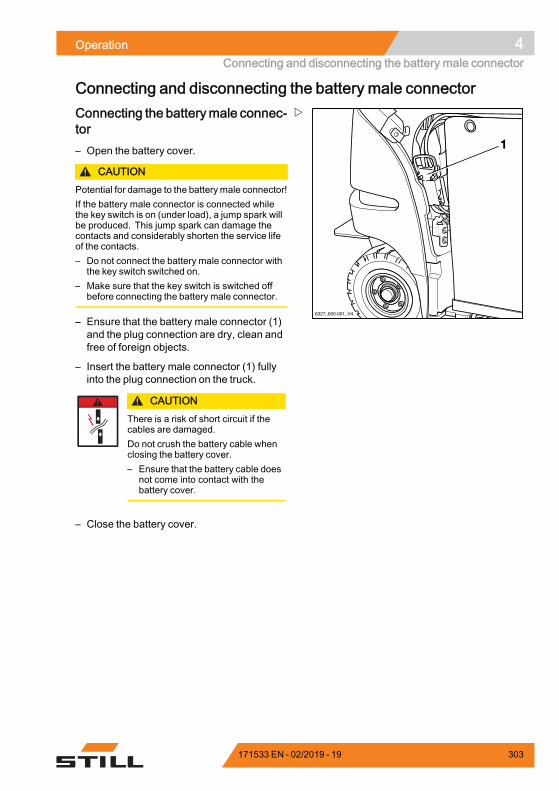
Operation 4Connecting and disconnecting the battery male connector
Connecting and disconnecting the battery male connector
6327_600-001_V4
1
Connecting the batterymale connec-tor– Open the battery cover.
CAUTIONPotential for damage to the battery male connector!If the battery male connector is connected whilethe key switch is on (under load), a jump spark willbe produced. This jump spark can damage thecontacts and considerably shorten the service lifeof the contacts.– Do not connect the battery male connector with
the key switch switched on.– Make sure that the key switch is switched off
before connecting the battery male connector.
– Ensure that the battery male connector (1)and the plug connection are dry, clean andfree of foreign objects.
– Insert the battery male connector (1) fullyinto the plug connection on the truck.
CAUTIONThere is a risk of short circuit if thecables are damaged.Do not crush the battery cable whenclosing the battery cover.– Ensure that the battery cable does
not come into contact with thebattery cover.
– Close the battery cover.
171533 EN - 02/2019 - 19 303
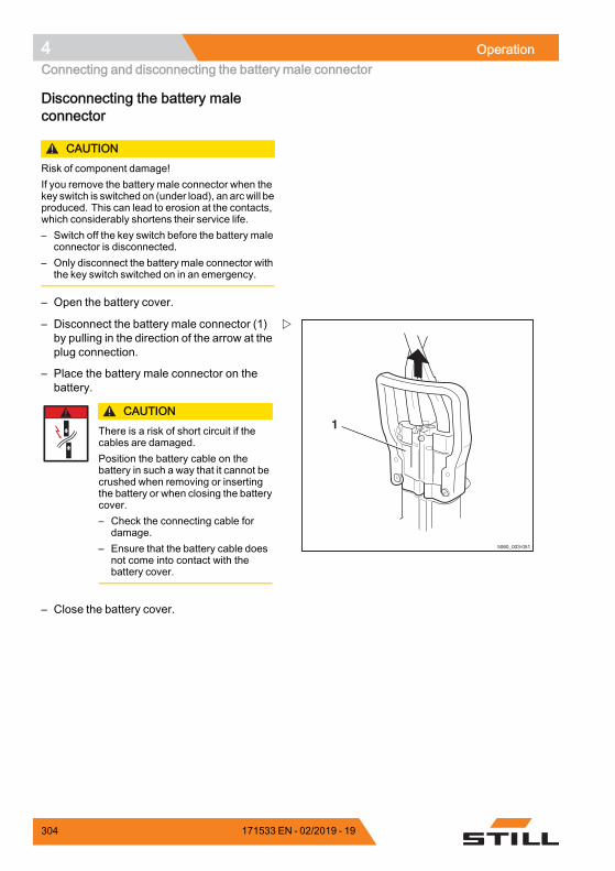
4 OperationConnecting and disconnecting the battery male connector
Disconnecting the battery maleconnector
CAUTIONRisk of component damage!If you remove the battery male connector when thekey switch is switched on (under load), an arcwill beproduced. This can lead to erosion at the contacts,which considerably shortens their service life.– Switch off the key switch before the battery male
connector is disconnected.– Only disconnect the battery male connector with
the key switch switched on in an emergency.
– Open the battery cover.
1
5060_003-051
– Disconnect the battery male connector (1)by pulling in the direction of the arrow at theplug connection.
– Place the battery male connector on thebattery.
CAUTIONThere is a risk of short circuit if thecables are damaged.Position the battery cable on thebattery in such a way that it cannot becrushed when removing or insertingthe battery or when closing the batterycover.– Check the connecting cable for
damage.– Ensure that the battery cable does
not come into contact with thebattery cover.
– Close the battery cover.
304 171533 EN - 02/2019 - 19
Operation 4Handling the lead-acid battery
Handling the lead-acid batterySafety regulations for handling thebattery– National statutory provisions for the countryof usemust be followedwhen setting up andoperating battery charging stations.
CAUTIONRisk of component damage!Incorrect connection or incorrectoperation of the charging station orbattery charger may result in damageto components.– Follow the operating instructions
for the charging station or batterycharger and for the battery.
– Observe the following safety regulationswhen maintaining, charging and changingthe battery.
Maintenance personnelBatteries may only be charged, maintainedor replaced by properly trained personnelin accordance with the instructions from themanufacturers of the battery, battery chargerand truck.
– Follow the handling instructions for thebattery and the operating instructions forthe battery charger.
WARNINGRisk of crushing/shearing!The battery is very heavy. There is arisk of serious injury if any parts of thebody are caught under the battery.There is a risk of injury if any partsof the body are wedged between thebattery cover and the edge of thechassis when the battery cover isclosed.– Always wear safety shoes when
replacing the battery.– Only close the battery cover if there
is no part of the body between thebattery cover and the edge of thechassis.
171533 EN - 02/2019 - 19 305
4 OperationHandling the lead-acid battery
The battery must only be replaced in accor-dance with the directions in these operatinginstructions.
– When charging andmaintaining the battery,observe the manufacturer's maintenanceinstructions for the battery and the batterycharger.
Fire protection measures
DANGERRisk of explosion due to flammablegases!During charging, the battery releasesa mixture of oxygen and hydrogen(oxyhydrogen gas). This gas mixtureis explosive and must not be ignited.Theremust be no flammablematerialsor spark-forming operating materialswithin 2 m of either the truck when itis parked for charging or the batterycharger.– When working with batteries, take
the following safety precautions.
– Keep away from open flames and do notsmoke.
– Ensure that work areas are adequatelyventilated.
– Disconnect the battery male connectorbefore charging and only when the truckand battery charger are switched off.
– The battery cover must remain open duringcharging.
– Expose the surfaces of the battery cells.
– Do not place any metal objects on thebattery.
– Fully open any protective structures (e.g.fabric-covered cab).
– Have fire extinguishing equipment ready.
306 171533 EN - 02/2019 - 19
Operation 4Handling the lead-acid battery
Battery weight and dimensions
DANGERRisk of tipping due to change in battery weight!The battery weight and dimensions affect the sta-bility of the truck. When replacing the battery, theweight ratios must not be changed. The batteryweight must remain within the weight range speci-fied on the nameplate.– Do not remove or change the position of ballast
weights.– Note the battery weight.
Performing battery maintenanceThe cell covers of the battery must be kept dryand clean.
Terminals and cable shoes must be clean,lightly coated with battery grease and screwedon tightly.
– Neutralise any spilt battery acid immedi-ately.
– Observe the safety regulations for handlingbattery acid; see the chapter entitled"Battery acid".
171533 EN - 02/2019 - 19 307
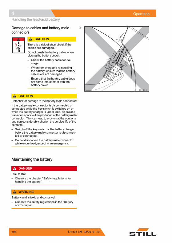
4 OperationHandling the lead-acid battery
6210_600-001
Damage to cables and battery maleconnectors
CAUTIONThere is a risk of short circuit if thecables are damaged.Do not crush the battery cable whenclosing the battery cover.– Check the battery cable for da-
mage.– When removing and reinstalling
the battery, ensure that the batterycables are not damaged.
– Ensure that the battery cable doesnot come into contact with thebattery cover.
CAUTIONPotential for damage to the battery male connector!If the battery male connector is disconnected orconnected while the key switch is switched on orwhile the battery charger is under load, an arc or atransition spark will be produced at the battery maleconnector. This can lead to erosion at the contactsand can considerably shorten the service life of thecontacts.– Switch off the key switch or the battery charger
before the battery male connector is disconnec-ted or connected.
– Do not disconnect the battery male connectorwhile under load, except in an emergency.
Maintaining the battery
DANGERRisk to life!– Observe the chapter "Safety regulations for
handling the battery".
WARNINGBattery acid is toxic and corrosive!– Observe the safety regulations in the "Battery
acid" chapter.
308 171533 EN - 02/2019 - 19
Operation 4Handling the lead-acid battery
NOTE
Battery maintenance is carried out in accor-dance with the battery manufacturer's opera-ting instructions! The operating instructionsfor the battery charger must also be followed.Only the instructions that camewith the batterycharger are valid. If any of these instructionsare not available, please request them fromthe dealer.
The battery maintenance is composed of thefollowing sections "Checking the battery con-dition, acid level and acid density", "Checkingthe battery charge status", "Charging the bat-tery" and "Equalising charge to prevent a deepdischarge of the battery" together.
171533 EN - 02/2019 - 19 309
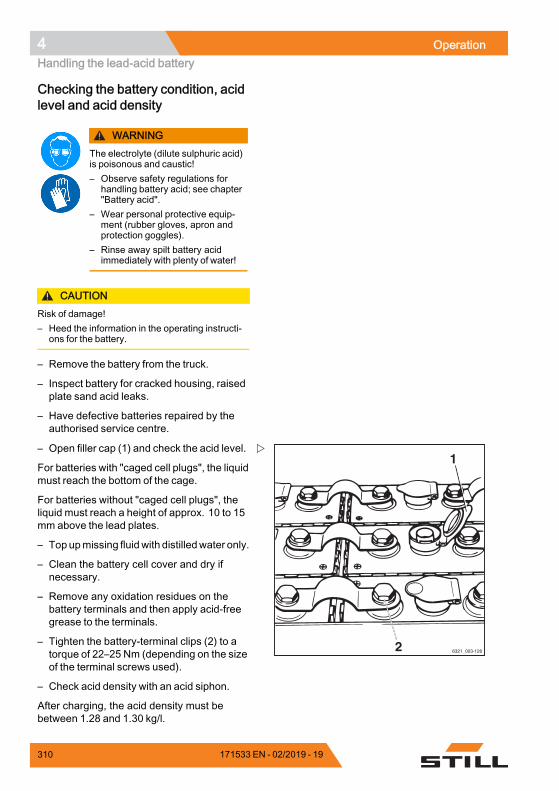
4 OperationHandling the lead-acid battery
Checking the battery condition, acidlevel and acid density
WARNINGThe electrolyte (dilute sulphuric acid)is poisonous and caustic!– Observe safety regulations for
handling battery acid; see chapter"Battery acid".
– Wear personal protective equip-ment (rubber gloves, apron andprotection goggles).
– Rinse away spilt battery acidimmediately with plenty of water!
CAUTIONRisk of damage!– Heed the information in the operating instructi-
ons for the battery.
– Remove the battery from the truck.
– Inspect battery for cracked housing, raisedplate sand acid leaks.
– Have defective batteries repaired by theauthorised service centre.
6321_003-126
1
2
– Open filler cap (1) and check the acid level.
For batteries with "caged cell plugs", the liquidmust reach the bottom of the cage.
For batteries without "caged cell plugs", theliquid must reach a height of approx. 10 to 15mm above the lead plates.
– Topupmissing fluidwith distilledwater only.
– Clean the battery cell cover and dry ifnecessary.
– Remove any oxidation residues on thebattery terminals and then apply acid-freegrease to the terminals.
– Tighten the battery-terminal clips (2) to atorque of 22–25 Nm (depending on the sizeof the terminal screws used).
– Check acid density with an acid siphon.
After charging, the acid density must bebetween 1.28 and 1.30 kg/l.
310 171533 EN - 02/2019 - 19
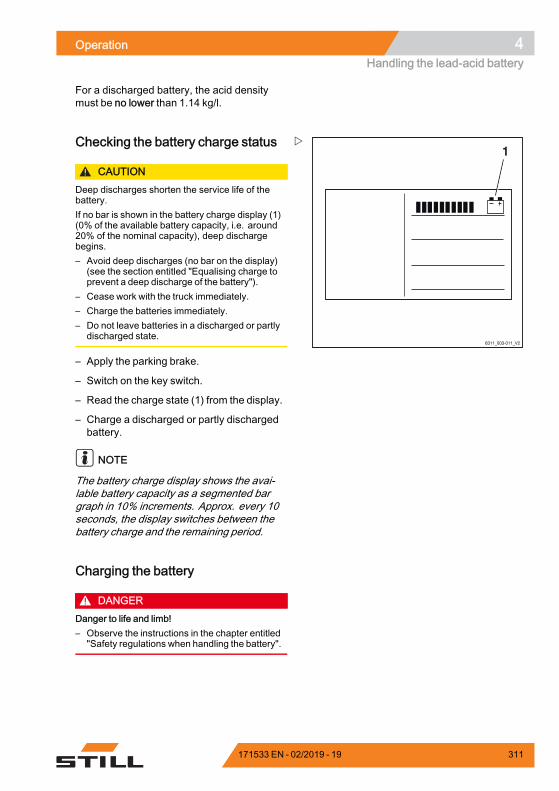
Operation 4Handling the lead-acid battery
For a discharged battery, the acid densitymust be no lower than 1.14 kg/l.
6311_003-011_V2
1Checking the battery charge status
CAUTIONDeep discharges shorten the service life of thebattery.If no bar is shown in the battery charge display (1)(0% of the available battery capacity, i.e. around20% of the nominal capacity), deep dischargebegins.– Avoid deep discharges (no bar on the display)
(see the section entitled "Equalising charge toprevent a deep discharge of the battery").
– Cease work with the truck immediately.– Charge the batteries immediately.– Do not leave batteries in a discharged or partly
discharged state.
– Apply the parking brake.
– Switch on the key switch.
– Read the charge state (1) from the display.
– Charge a discharged or partly dischargedbattery.
NOTE
The battery charge display shows the avai-lable battery capacity as a segmented bargraph in 10% increments. Approx. every 10seconds, the display switches between thebattery charge and the remaining period.
Charging the battery
DANGERDanger to life and limb!– Observe the instructions in the chapter entitled
"Safety regulations when handling the battery".
171533 EN - 02/2019 - 19 311
4 OperationHandling the lead-acid battery
WARNINGBattery acid is toxic and corrosive!– Observe the safety regulations in the chapter
entitled "Battery acid".
CAUTIONRisk of component damage!Incorrect connection or operation ofthe charging station or battery chargermay result in damage to components!– Follow the operating instructions
for the charging station or batterycharger and for the battery.
CAUTIONPossibility of damaging the battery male connec-tors!Ensure that the key switch or battery charger isswitched off before the battery male connectors aredisconnected or connected.
NOTE
Battery maintenance is carried out in accor-dance with the battery manufacturer's opera-ting instructions! The operating instructionsfor the battery charger must also be followed.Only the instructions that camewith the batterycharger are valid. If any of these instructionsare missing, please request them from thedealer.
To read the battery charging state, see thesection entitled "Checking the battery chargestatus".
– Park the truck securely.
– Open any protective structures fully (e.g.fabric-covered cab).
– Open battery cover completely.
– Do not place any metal objects or tools onthe battery.
– Keep away from open flames and do notsmoke.
– Check the battery cable and the chargingcable for damage, and have them replaced
312 171533 EN - 02/2019 - 19
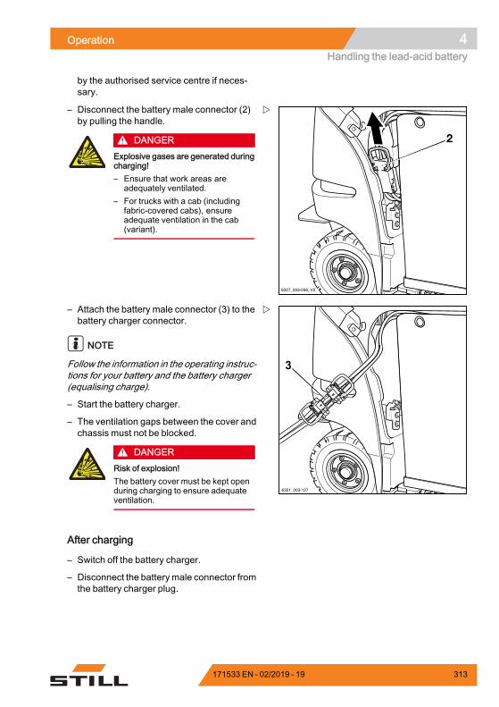
Operation 4Handling the lead-acid battery
by the authorised service centre if neces-sary.
6327_003-036_V2
2
– Disconnect the battery male connector (2)by pulling the handle.
DANGERExplosive gases are generated duringcharging!– Ensure that work areas are
adequately ventilated.– For trucks with a cab (including
fabric-covered cabs), ensureadequate ventilation in the cab(variant).
6321_003-127
3
– Attach the battery male connector (3) to thebattery charger connector.
NOTE
Follow the information in the operating instruc-tions for your battery and the battery charger(equalising charge).
– Start the battery charger.
– The ventilation gaps between the cover andchassis must not be blocked.
DANGERRisk of explosion!The battery cover must be kept openduring charging to ensure adequateventilation.
After charging
– Switch off the battery charger.
– Disconnect the batterymale connector fromthe battery charger plug.
171533 EN - 02/2019 - 19 313
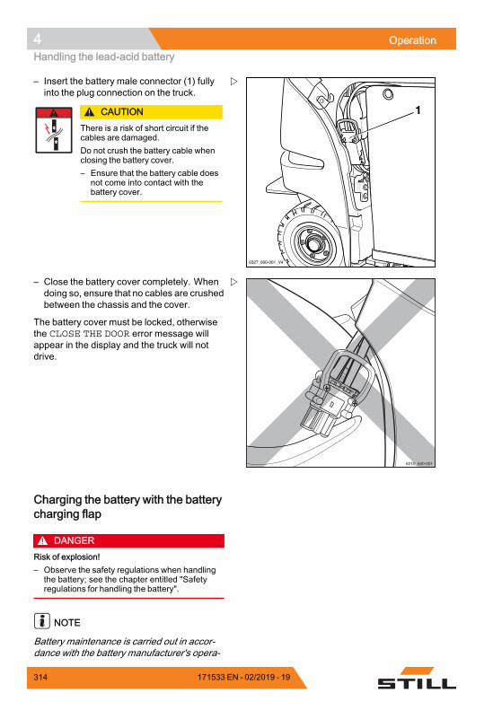
4 OperationHandling the lead-acid battery
6327_600-001_V4
1
– Insert the battery male connector (1) fullyinto the plug connection on the truck.
CAUTIONThere is a risk of short circuit if thecables are damaged.Do not crush the battery cable whenclosing the battery cover.– Ensure that the battery cable does
not come into contact with thebattery cover.
6210_600-001
– Close the battery cover completely. Whendoing so, ensure that no cables are crushedbetween the chassis and the cover.
The battery cover must be locked, otherwisethe CLOSE THE DOOR error message willappear in the display and the truck will notdrive.
Charging the battery with the batterycharging flap
DANGERRisk of explosion!– Observe the safety regulations when handling
the battery; see the chapter entitled "Safetyregulations for handling the battery".
NOTE
Battery maintenance is carried out in accor-dance with the battery manufacturer's opera-
314 171533 EN - 02/2019 - 19
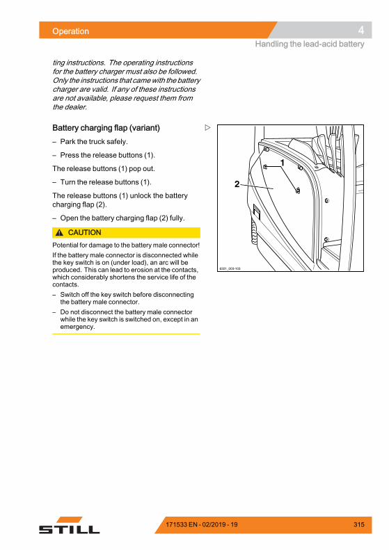
Operation 4Handling the lead-acid battery
ting instructions. The operating instructionsfor the battery charger must also be followed.Only the instructions that camewith the batterycharger are valid. If any of these instructionsare not available, please request them fromthe dealer.
6321_003-103
1
2
Battery charging flap (variant)– Park the truck safely.
– Press the release buttons (1).
The release buttons (1) pop out.
– Turn the release buttons (1).
The release buttons (1) unlock the batterycharging flap (2).
– Open the battery charging flap (2) fully.
CAUTIONPotential for damage to the battery male connector!If the battery male connector is disconnected whilethe key switch is on (under load), an arc will beproduced. This can lead to erosion at the contacts,which considerably shortens the service life of thecontacts.– Switch off the key switch before disconnecting
the battery male connector.– Do not disconnect the battery male connector
while the key switch is switched on, except in anemergency.
171533 EN - 02/2019 - 19 315
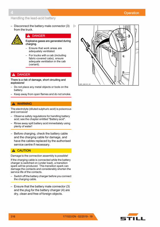
4 OperationHandling the lead-acid battery
6321_003-101_V3
3
– Disconnect the battery male connector (3)from the truck.
DANGERExplosive gases are generated duringcharging.– Ensure that work areas are
adequately ventilated.– For trucks with a cab (including
fabric-covered cabs), ensureadequate ventilation in the cab(variant).
DANGERThere is a risk of damage, short circuiting andexplosions!– Do not place any metal objects or tools on the
battery.– Keep away from open flames and do not smoke.
WARNINGThe electrolyte (diluted sulphuric acid) is poisonousand corrosive!– Observe safety regulations for handling battery
acid; see the chapter entitled "Battery acid".– Rinse away spilt battery acid immediately using
plenty of water!
– Before charging, check the battery cableand the charging cable for damage, andhave the cables replaced by the authorisedservice centre if necessary.
CAUTIONDamage to the connection assembly is possible!If the charging cable is connected while the batterycharger is switched on (under load), a transitionspark will be produced. This transition spark candamage the contacts and considerably shorten theservice life of the contacts.– Switch off the battery charger before you connect
the charging cable.
– Ensure that the battery male connector (3)and the plug for the battery charger (4) aredry, clean and free of foreign objects.
316 171533 EN - 02/2019 - 19
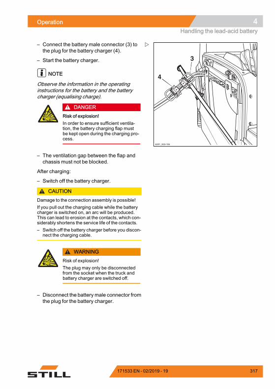
Operation 4Handling the lead-acid battery
6321_003-105
4
3
– Connect the battery male connector (3) tothe plug for the battery charger (4).
– Start the battery charger.
NOTE
Observe the information in the operatinginstructions for the battery and the batterycharger (equalising charge).
DANGERRisk of explosion!In order to ensure sufficient ventila-tion, the battery charging flap mustbe kept open during the charging pro-cess.
– The ventilation gap between the flap andchassis must not be blocked.
After charging:
– Switch off the battery charger.
CAUTIONDamage to the connection assembly is possible!If you pull out the charging cable while the batterycharger is switched on, an arc will be produced.This can lead to erosion at the contacts, which con-siderably shortens the service life of the contacts.– Switch off the battery charger before you discon-
nect the charging cable.
WARNINGRisk of explosion!The plug may only be disconnectedfrom the socket when the truck andbattery charger are switched off.
– Disconnect the batterymale connector fromthe plug for the battery charger.
171533 EN - 02/2019 - 19 317
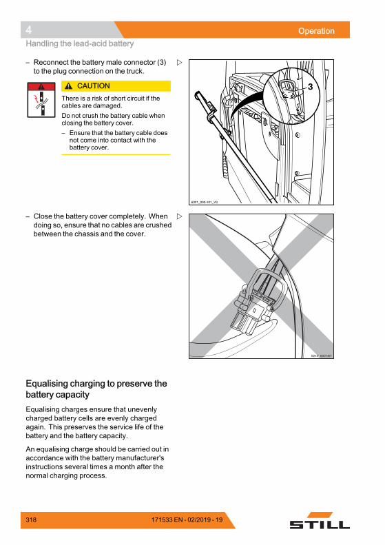
4 OperationHandling the lead-acid battery
6321_003-101_V3
3
– Reconnect the battery male connector (3)to the plug connection on the truck.
CAUTIONThere is a risk of short circuit if thecables are damaged.Do not crush the battery cable whenclosing the battery cover.– Ensure that the battery cable does
not come into contact with thebattery cover.
6210_600-001
– Close the battery cover completely. Whendoing so, ensure that no cables are crushedbetween the chassis and the cover.
Equalising charging to preserve thebattery capacityEqualising charges ensure that unevenlycharged battery cells are evenly chargedagain. This preserves the service life of thebattery and the battery capacity.
An equalising charge should be carried out inaccordance with the battery manufacturer'sinstructions several times a month after thenormal charging process.
318 171533 EN - 02/2019 - 19
Operation 4Handling the lead-acid battery
NOTE
Depending on the battery charger used, theequalising chargemay not begin until 24 hourshave elapsed. A period when no shifts arerunning, such as the weekend, is thereforeideal for performing the equalising charge.
– Observe the information in the operatinginstructions of the battery charger regardinghow to perform an equalising charge.
Starting the equalising charge– Charge the battery.
– After charging, leave the battery in thecharger.
The battery charger remains switched on.Depending on the type of battery charger,the equalising charge begins between 6 and24 hours after the end of the actual chargingprocess. The equalising charge takes up to2 hours.
– Please refer to the operating instruc-tions from the manufacturer of the batterycharger.
Ending the equalising chargeThe equalising charge ends automatically. Ifthe battery is required during this process, youcan interrupt the equalising charge by pushingthe "stop button" on the battery charger.
– Please refer to the operating instruc-tions from the manufacturer of the batterycharger.
CAUTIONDamage to the connection assembly is possible!If you disconnect the charging cable while the bat-tery charger is switched on, an arc will be produced.This can lead to erosion at the contacts, which con-siderably shortens the service life of the contacts.– Switch off the battery charger before you discon-
nect the charging cable.
– Switch off the battery charger.
– Disconnect the batterymale connector fromthe plug for the battery charger.
171533 EN - 02/2019 - 19 319

4 OperationHandling the lead-acid battery
– Insert the battery male connector fully intothe plug connection on the truck.
320 171533 EN - 02/2019 - 19

Operation 4Handling the lithium-ion battery
Handling the lithium-ion batterySafety regulations for handling thelithium-ion battery
First-aid measures
WARNINGRisk of injury!Escaping gases can lead to breathing difficulties.
Course of action required if gases or liquidsescape
– Immediately ventilate the area or go out intothe fresh air; in more serious cases, call adoctor immediately.
Skin irritation can occur in the event of contactwith the skin.
– Thoroughly wash the skin with soap andwater.
Eye irritation can occur in the event of contactwith the eyes.
– Immediately rinse eyes thoroughly withwater for 15 minutes, then consult a doctor.
Maintenance personnelThe lithium-ion battery is virtually mainte-nance-free and can be charged by the driver.
– If you have any questions, please contactyour authorised service centre.
– The handling instruction for the battery andthe operating instructions for the batterycharger must be followed.
– Observe the following safety regulationswhen maintaining, charging and changingthe battery.
171533 EN - 02/2019 - 19 321
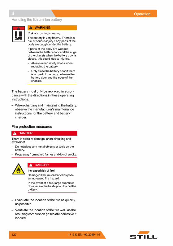
4 OperationHandling the lithium-ion battery
WARNINGRisk of crushing/shearing!The battery is very heavy. There is arisk of serious injury if any parts of thebody are caught under the battery.If parts of the body are wedgedbetween the battery door and the edgeof the chassis when the battery door isclosed, this could lead to injuries.– Always wear safety shoes when
replacing the battery.– Only close the battery door if there
is no part of the body between thebattery door and the edge of thechassis.
The battery must only be replaced in accor-dance with the directions in these operatinginstructions.
– When charging andmaintaining the battery,observe the manufacturer's maintenanceinstructions for the battery and batterycharger.
Fire protection measures
DANGERThere is a risk of damage, short circuiting andexplosion!– Do not place any metal objects or tools on the
battery.– Keepaway fromnaked flamesanddonot smoke.
DANGERIncreased risk of fire!Damaged lithium-ion batteries posean increased fire hazard.In the event of a fire, large quantitiesof water are the best option to cool thebattery.
– Evacuate the location of the fire as quicklyas possible.
– Ventilate the location of the fire well, as theresulting combustion gases are corrosive ifinhaled.
322 171533 EN - 02/2019 - 19
Operation 4Handling the lithium-ion battery
– Inform the fire brigade that lithium-ionbatteries are affected by the fire.
– Observe the information provided bythe battery manufacturer regarding theprocedure in the event of a fire.
Battery weight and dimensions
DANGERRisk of tipping due to change in battery weight!The battery weight and dimensions affect the sta-bility of the truck. When replacing the battery, theweight ratios must not be changed. The batteryweight must remain within the weight range speci-fied on the nameplate.
– Do not remove or change the position ofballast weights.
– Observe the battery weight.
General safety regulations for lithium-ionbatteriesThe following safety regulations generallyapply to operating lithium-ion batteries.
– Comply with the specifications statedin the safety data sheets of the batterymanufacturer.
– Protect the battery against mechanicaldamage to prevent internal short circuits.
– If batteries have even the slightest externaldamage, dispose of them in accordancewith national regulations for the country inwhich they are being used.
– Do not expose batteries directly to contin-uously high temperatures or heat sources,such as direct sunlight.
– Train employees in how to handle lithium-ion batteries correctly.
171533 EN - 02/2019 - 19 323
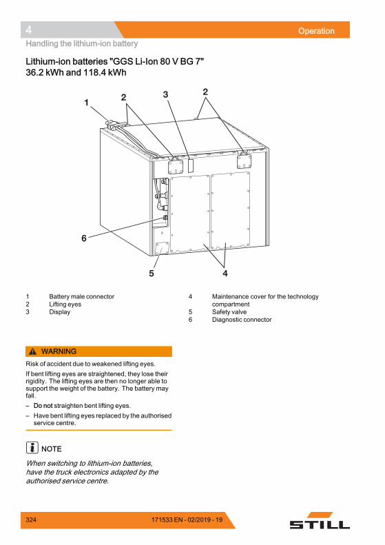
4 OperationHandling the lithium-ion battery
Lithium-ion batteries "GGS Li-Ion 80 V BG 7"36.2 kWh and 118.4 kWh
6
1 2 3 2
5 4
1 Battery male connector2 Lifting eyes3 Display
4 Maintenance cover for the technologycompartment
5 Safety valve6 Diagnostic connector
WARNINGRisk of accident due to weakened lifting eyes.If bent lifting eyes are straightened, they lose theirrigidity. The lifting eyes are then no longer able tosupport the weight of the battery. The battery mayfall.– Do not straighten bent lifting eyes.– Have bent lifting eyes replaced by the authorised
service centre.
NOTE
When switching to lithium-ion batteries,have the truck electronics adapted by theauthorised service centre.
324 171533 EN - 02/2019 - 19

Operation 4Handling the lithium-ion battery
Display messages on the display-operating unit
The following table describes the messages that appear on the display-operating unit for thelithium-ion battery:
Message Meaning Remedy/reaction
LITHIUM BATTERYTEMPERATURE
The battery temperatureis lower than −15°C orhigher than 60°C.If the temperaturerises above 60°C, thetemperature LED flashesin the battery display.If the temperaturerises above 65°C, thetemperature LED lights upin the battery display andthe truck switches off.
Temperature < −15°C:allow the truck toacclimatise in a warmerarea.Temperature > 60°C:allow the truck to cooldown.
LITHIUM BATTERYRESTRICTION
The truck performance isgradually reduced.The truck goes intoemergency operation.
Switch off the truck andthen switch it on again.If the error occursfrequently, notify yourauthorised service centre.
LITHIUM BATTERYERROR
The battery has an errorand reports it to the truckcontrol unit.The truck switches offafter five seconds androlls to a stop. Withinthis five-second period,the truck slows downaccording to the selectedgear.The service LED lights upin the battery display.
Notify the authorisedservice centre.
.
Regulations for storing lithium-ionbatteries
NOTE
Lithium-ion batteries are classified as danger-ous goods according to class 9.
171533 EN - 02/2019 - 19 325
4 OperationHandling the lithium-ion battery
The following recommendations apply:• Store batteries at a height between 60 cmand 120 cm so that they are not damaged ifthey fall
• Store the batteries in a segregated areasuitable for fire protection (container orsafety cabinet)
• Store the batteries at a temperature be-tween +15°C and +30°C and air humidityfrom 0% to 80%
Observe the following regulations for safestorage of the batteries:
– Store batteries fixed onto pallets andsecured against overturning.
– Observe the floor load capacity of thestorage area; refer to the manufacturer'sspecifications regarding battery weight
– To protect batteries against moisture, donot store them directly on the floor
– Due to the fire risk, store batteries outsidebuildings
– Store in a cool, dry and well-ventilated area
– Never subject the battery to temperaturesbelow -35°C and above 80°C.
Long-term storage below -10°Cor above 50°Chas a negative impact on the service life of thebattery.
– After twelve months, check the chargingstate of the battery and recharge if neces-sary
– Cordon off the warehouse area
– Only persons who are aware of the risksand safety regulationsmay access this area
– Protect against direct sunlight
– Protect against precipitation
– Store in a way that protects the batteriesagainst short circuits
– Store batteries at a safe distance fromflammable materials
– Do not store batteries together with metallicobjects
326 171533 EN - 02/2019 - 19

Operation 4Handling the lithium-ion battery
– Store lithium-ion batteries separately fromother types of batteries (no mixed storage).
– Maintain a safety margin of at least 2.5 m toother goods
– To avoid a deep discharge, observe thespecifications of the battery manufacturerregarding the maximum permissible stor-age period
– If you have any questions, please contactyour authorised service centre.
171533 EN - 02/2019 - 19 327

4 OperationHandling the lithium-ion battery
Checking the battery charge stateThe charge state of the lithium-ion battery canbe read on the display-operating unit of thetruck and on the lithium-ion battery display.
6311_003-011_V2
1Reading the display-operating unit– Apply the parking brake.
– Switch on the key switch.
– Read the charge state (1) from the display.
– Charge a discharged or partly dischargedbattery.
NOTE
The battery charge display shows the avai-lable battery capacity as a segmented bargraph in 10% increments. Approx. every10 seconds, the display switches between thebattery charge and the remaining period.
Meaning of the bar graph on the display• The remaining two bars flash:The charge state is <30 %.The battery must be recharged soon.
• No bars are displayed:The charge state is <15 %.Charge the battery.The "Lifting" hydraulic function is sloweddown.The maximum driving speed is limited. Thisspeed can be parameterised specifically foreach truck by the authorised service centre.
328 171533 EN - 02/2019 - 19
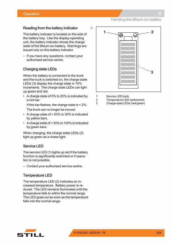
Operation 4Handling the lithium-ion battery
1 2
3
1 Service LED (red)2 Temperature LED (yellow/red)3 Charge state LEDs (red/green)
Reading from the battery indicatorThe battery indicator is located on the side ofthe battery tray. Like the display-operatingunit, the battery indicator shows the chargestate of the lithium-ion battery. Warnings areissued only on this battery indicator.
– If you have any questions, contact yourauthorised service centre.
Charging state LEDs
When the battery is connected to the truckand the truck is switched on, the charge stateLEDs (3) display the charge state in 10%increments. The charge state LEDs can lightup green and red.• A charge state of 0% to 20% is indicated bya red bar.If this bar flashes, the charge state is < 2%.The truck can no longer be moved.
• A charge state of > 20% to 30% is indicatedby yellow bars.
• A charge state of > 30% to 100% is indicatedby green bars.
When charging, the charge state LEDs (3)light up green as a chase light.
Service LEDThe service LED (1) lights up red if the batteryfunction is significantly restricted or if opera-tion is not possible.
– Contact your authorised service centre.
Temperature LEDThe temperature LED (2) indicates an in-creased temperature. Battery power is re-duced. The LED remains illuminated until thetemperature falls to within the normal range.The LED goes out as soon as the temperaturefalls into the normal range.
171533 EN - 02/2019 - 19 329
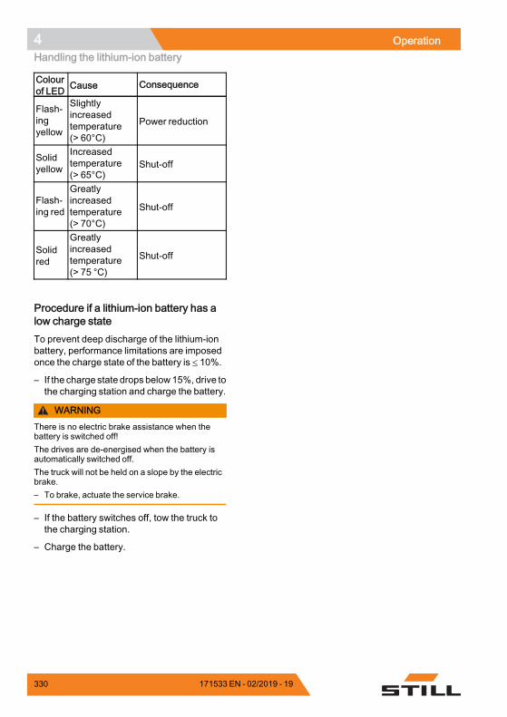
4 OperationHandling the lithium-ion battery
Colourof LED Cause Consequence
Flash-ingyellow
Slightlyincreasedtemperature(> 60°C)
Power reduction
Solidyellow
Increasedtemperature(> 65°C)
Shut-off
Flash-ing red
Greatlyincreasedtemperature(> 70°C)
Shut-off
Solidred
Greatlyincreasedtemperature(> 75 °C)
Shut-off
.
Procedure if a lithium-ion battery has alow charge stateTo prevent deep discharge of the lithium-ionbattery, performance limitations are imposedonce the charge state of the battery is ≤ 10%.
– If the charge state drops below15%, drive tothe charging station and charge the battery.
WARNINGThere is no electric brake assistance when thebattery is switched off!The drives are de-energised when the battery isautomatically switched off.The truck will not be held on a slope by the electricbrake.– To brake, actuate the service brake.
– If the battery switches off, tow the truck tothe charging station.
– Charge the battery.
330 171533 EN - 02/2019 - 19
Operation 4Handling the lithium-ion battery
Charging the battery
CAUTIONRisk of component damage!Incorrect connection or incorrect operation of thecharging station or battery charger may result indamage to components!– Follow the operating instructions for the charging
station or battery charger and for the battery.
CAUTIONRisk of component damage!Battery male connectors and battery chargerconnectors from different manufacturers are notcompatible and may cause damage.– Usebatterymale connectors andbattery charger
connectors produced by the samemanufacturer.– If the connectors are from different manufac-
turers, please contact your authorised servicecentre.
NOTE
To prevent deep discharge of the lithium-ionbattery, performance limitations are imposedonce the charge state of the battery drops toa certain level. The battery must be chargedbefore the charge state drops below 15%.
To read the battery charge state; see thesection entitled "Checking the battery chargestatus".
– Park the truck safely.
– Fully open any protective structures (e.g.fabric-covered cab).
– Open the battery cover fully.
– Disconnect the battery male connector bypulling the handle.
– Do not place any metal objects or tools onthe battery.
– Keep away from naked flames and do notsmoke.
– Check the battery cables for damage.If necessary, have the battery cablesreplaced by the authorised service centre.
171533 EN - 02/2019 - 19 331
4 OperationHandling the lithium-ion battery
DANGERThere is a risk of damage, short circuiting andexplosion!– Do not place any metal objects or tools on the
battery.– Keep away from naked flames.– Do not smoke.
– Connect the battery male connector to theplug on the battery charger.
– Start the battery charger.
The charging process starts automatically.The display signals the charging process byilluminating the LEDS as a chase light.
The charger indicates when the battery is fullycharged. Only disconnect the battery from thecharger if there is no current is flowing.
The battery has no memory effect. Therefore,it can be charged in any charge state withoutthe capacity of the battery being impaired.
At ambient temperatures below 0°C, thecharging process will take much longer.
– Observe the information in the operatinginstructions for the battery and the batterycharger.
After chargingThe battery charger will stop automatically.
– Disconnect the batterymale connector fromthe plug for the battery charger.
– Insert the battery male connector fully intothe plug connection on the truck.
CAUTIONThere is a risk of short circuit if thecables are damaged.Do not crush the charging cable whenclosing the battery cover.– Make sure that the charging cable
does not come into contact with thebattery cover.
332 171533 EN - 02/2019 - 19
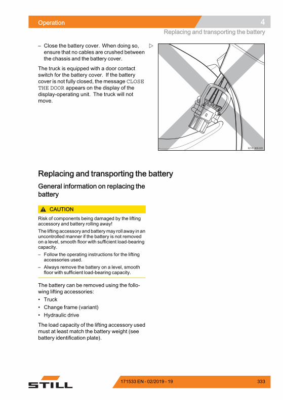
Operation 4Replacing and transporting the battery
6210_600-001
– Close the battery cover. When doing so,ensure that no cables are crushed betweenthe chassis and the battery cover.
The truck is equipped with a door contactswitch for the battery cover. If the batterycover is not fully closed, the message CLOSETHE DOOR appears on the display of thedisplay-operating unit. The truck will notmove.
Replacing and transporting the batteryGeneral information on replacing thebattery
CAUTIONRisk of components being damaged by the liftingaccessory and battery rolling away!The lifting accessory andbatterymay roll away in anuncontrolled manner if the battery is not removedon a level, smooth floor with sufficient load-bearingcapacity.– Follow the operating instructions for the lifting
accessories used.– Always remove the battery on a level, smooth
floor with sufficient load-bearing capacity.
The battery can be removed using the follo-wing lifting accessories:• Truck• Change frame (variant)• Hydraulic drive
The load capacity of the lifting accessory usedmust at least match the battery weight (seebattery identification plate).
171533 EN - 02/2019 - 19 333
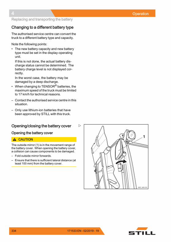
4 OperationReplacing and transporting the battery
Changing to a different battery typeThe authorised service centre can convert thetruck to a different battery type and capacity.
Note the following points:• The new battery capacity and new batterytype must be set in the display-operatingunit.If this is not done, the actual battery dis-charge status cannot be determined. Thebattery charge level is not displayed cor-rectly.In the worst case, the battery may bedamaged by a deep discharge.
• When changing to TENSOR® batteries, themaximum speed of the truckmust be limitedto 17 km/h for technical reasons.
– Contact the authorised service centre in thissituation.
– Only use lithium-ion batteries that havebeen approved by STILL with this truck.
6327_600-010
1
Opening/closing the battery cover
Opening the battery cover
CAUTIONThe outside mirror (1) is in the movement range ofthe battery cover. When opening the battery cover,a collision can cause components to be damaged.– Fold outside mirror forwards.– Ensure that there is sufficient lateral distance (at
least 100 mm) from the battery cover.
334 171533 EN - 02/2019 - 19
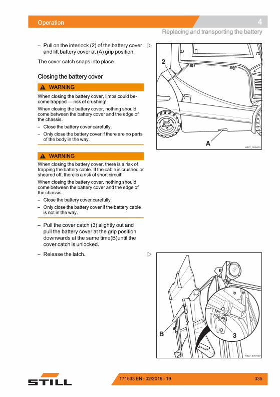
Operation 4Replacing and transporting the battery
6327_003-010
2
A
– Pull on the interlock (2) of the battery coverand lift battery cover at (A) grip position.
The cover catch snaps into place.
Closing the battery cover
WARNINGWhen closing the battery cover, limbs could be-come trapped— risk of crushing!When closing the battery cover, nothing shouldcome between the battery cover and the edge ofthe chassis.– Close the battery cover carefully.– Only close the battery cover if there are no parts
of the body in the way.
WARNINGWhen closing the battery cover, there is a risk oftrapping the battery cable. If the cable is crushed orsheared off, there is a risk of short circuit!When closing the battery cover, nothing shouldcome between the battery cover and the edge ofthe chassis.– Close the battery cover carefully.– Only close the battery cover if the battery cable
is not in the way.
– Pull the cover catch (3) slightly out andpull the battery cover at the grip positiondownwards at the same time(B)until thecover catch is unlocked.
6327_600-009
B 3
– Release the latch.
171533 EN - 02/2019 - 19 335
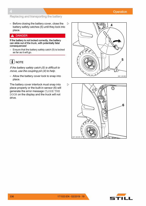
4 OperationReplacing and transporting the battery
6321_003-085
5
4– Before closing the battery cover, close thebattery safety catches (5) until they lock intoplace.
DANGERIf the battery is not locked correctly, the batterycan slide out of the truck, with potentially fatalconsequences!– Ensure that the battery safety catch (5) is locked
as far as it will go.
NOTE
If the battery safety catch (5) is difficult tomove, use the coupling pin (4) to help.
– Allow the battery cover lock to snap intoplace.
6327_600-005_V4
6
The battery cover interlock must snap intoplace properly or the built-in sensor (6) willgenerate the error message CLOSE THEDOOR on the display and the truck will notdrive.
336 171533 EN - 02/2019 - 19
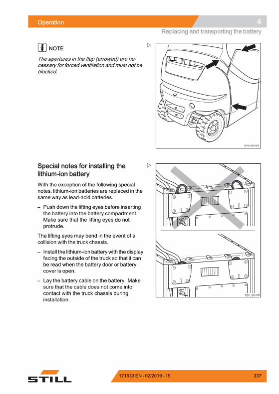
Operation 4Replacing and transporting the battery
6210_600-002
NOTE
The apertures in the flap (arrowed) are ne-cessary for forced ventilation and must not beblocked.
Special notes for installing thelithium-ion batteryWith the exception of the following specialnotes, lithium-ion batteries are replaced in thesame way as lead-acid batteries.
– Push down the lifting eyes before insertingthe battery into the battery compartment.Make sure that the lifting eyes do notprotrude.
The lifting eyes may bend in the event of acollision with the truck chassis.
– Install the lithium-ion batterywith the displayfacing the outside of the truck so that it canbe read when the battery door or batterycover is open.
– Lay the battery cable on the battery. Makesure that the cable does not come intocontact with the truck chassis duringinstallation.
171533 EN - 02/2019 - 19 337
4 OperationReplacing and transporting the battery
Replacing the battery using forklifttruck or pallet truck
CAUTIONRisk of damage!The battery must only be removed on a level andsmooth floor in accordance with the operatinginstructions of the truck or lift truck used.
Preparation– Park the truck safely.
– Open the battery cover.
CAUTIONRisk of component damage!If you remove the battery male connector when thekey switch is switched on (under load), an arcwill beproduced. This can lead to erosion at the contacts,which considerably shortens their service life.– Switch off the key switch before the battery male
connector is disconnected.– Only disconnect the battery male connector with
the key switch switched on in an emergency.
338 171533 EN - 02/2019 - 19
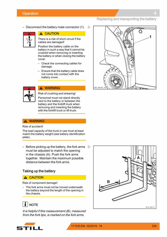
Operation 4Replacing and transporting the battery
6327_600-001_V4
1
– Disconnect the battery male connector (1).
CAUTIONThere is a risk of short circuit if thecables are damaged!Position the battery cable on thebattery in such a way that it cannot becrushed when removing or insertingthe battery or when closing the batterycover.– Check the connecting cables for
damage.– Ensure that the battery cable does
not come into contact with thebattery cover.
WARNINGRisk of crushing and shearing!Personnel must not stand directlynext to the battery or between thebattery and the forklift truck whenremoving and inserting the batterywith the forklift truck or lift truck.
WARNINGRisk of accident!The load capacity of the truck in use must at leastmatch the battery weight (see battery identificationplate).
6210_606-011
A
B
– Before picking up the battery, the fork armsmust be adjusted to match the openingin the chassis (A). Push the fork armstogether. Maintain the maximum possibledistance between the fork arms.
Taking up the battery
CAUTIONRisk of component damage!– The fork arms must not be moved underneath
the battery beyond the length of the opening inthe chassis.
NOTE
It is helpful if this measurement (B), measuredfrom the fork tips, is marked on the fork arms.
171533 EN - 02/2019 - 19 339
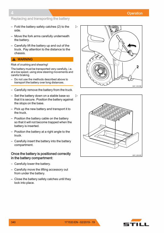
4 OperationReplacing and transporting the battery
6321_003-086
2
– Fold the battery safety catches (2) to theside.
– Move the fork arms carefully underneaththe battery.
– Carefully lift the battery up and out of thetruck. Pay attention to the distance to thechassis.
WARNINGRisk of crushing and shearing!The battery must be transported very carefully, i.e.at a low speed, using slow steeringmovements andcareful braking.– Do not use the methods described above to
transport the battery over long distances.
– Carefully remove the battery from the truck.
6321_003-002
– Set the battery down on a stable base sothat it is secure. Position the battery againstthe stops on the base.
– Pick up the new battery and transport it tothe truck.
– Position the battery cable on the batteryso that it will not become trapped when thebattery is inserted.
– Position the battery at a right angle to thetruck.
– Carefully insert the battery into the batterycompartment.
Once the battery is positioned correctlyin the battery compartment:– Carefully lower the battery.
– Carefully move the lifting accessory outfrom under the battery.
– Close the battery safety catches until theylock into place.
340 171533 EN - 02/2019 - 19
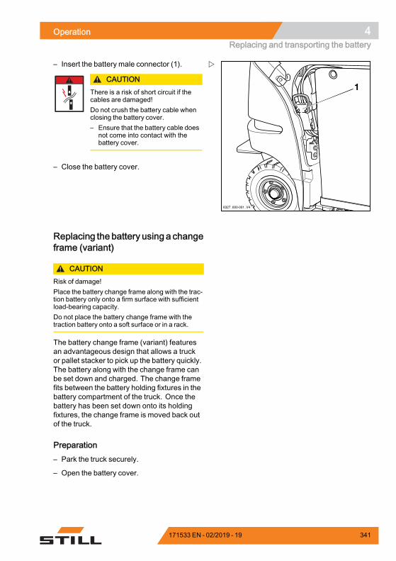
Operation 4Replacing and transporting the battery
6327_600-001_V4
1
– Insert the battery male connector (1).
CAUTIONThere is a risk of short circuit if thecables are damaged!Do not crush the battery cable whenclosing the battery cover.– Ensure that the battery cable does
not come into contact with thebattery cover.
– Close the battery cover.
Replacing the battery using a changeframe (variant)
CAUTIONRisk of damage!Place the battery change frame along with the trac-tion battery only onto a firm surface with sufficientload-bearing capacity.Do not place the battery change frame with thetraction battery onto a soft surface or in a rack.
The battery change frame (variant) featuresan advantageous design that allows a truckor pallet stacker to pick up the battery quickly.The battery along with the change frame canbe set down and charged. The change framefits between the battery holding fixtures in thebattery compartment of the truck. Once thebattery has been set down onto its holdingfixtures, the change frame is moved back outof the truck.
Preparation– Park the truck securely.
– Open the battery cover.
171533 EN - 02/2019 - 19 341
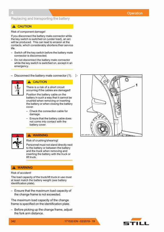
4 OperationReplacing and transporting the battery
CAUTIONRisk of component damage!If you disconnect the battery male connector whilethe key switch is switched on (under load), an arcwill be produced. This can lead to erosion at thecontacts, which considerably shortens their servicelife.– Switch off the key switch before the battery male
connector is disconnected.– Do not disconnect the battery male connector
while the key switch is switched on, except in anemergency.
6327_600-001_V4
1
– Disconnect the battery male connector (1).
CAUTIONThere is a risk of a short circuitoccurring if the cables are damaged!Position the battery cable on thebattery in such a way that it cannot becrushed when removing or insertingthe battery or when closing the batterycover.– Check the connection cable for
damage.– Ensure that the battery cable does
not come into contact with thebattery cover.
WARNINGRisk of crushing/shearing!Personnel must not stand directly nextto the battery or between the batteryand the truck when removing andinserting the battery with the truck orlift truck.
WARNINGRisk of accident!The load capacity of the truck/lift truck in use mustat least match the battery weight (see batteryidentification plate).
– Ensure that the maximum load capacity ofthe change frame is not exceeded.
The maximum load capacity of the changeframe is specified on the identification plate.
– Before picking up the change frame, adjustthe fork arm distance.
342 171533 EN - 02/2019 - 19
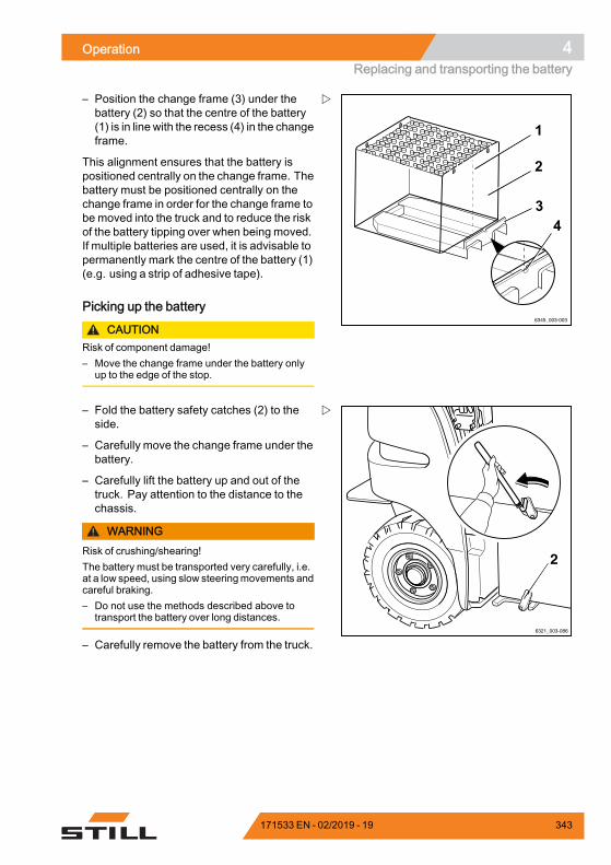
Operation 4Replacing and transporting the battery
– Position the change frame (3) under thebattery (2) so that the centre of the battery(1) is in line with the recess (4) in the changeframe.
This alignment ensures that the battery ispositioned centrally on the change frame. Thebattery must be positioned centrally on thechange frame in order for the change frame tobe moved into the truck and to reduce the riskof the battery tipping over when being moved.If multiple batteries are used, it is advisable topermanently mark the centre of the battery (1)(e.g. using a strip of adhesive tape).
Picking up the battery
CAUTIONRisk of component damage!– Move the change frame under the battery only
up to the edge of the stop.
6321_003-086
2
– Fold the battery safety catches (2) to theside.
– Carefully move the change frame under thebattery.
– Carefully lift the battery up and out of thetruck. Pay attention to the distance to thechassis.
WARNINGRisk of crushing/shearing!The battery must be transported very carefully, i.e.at a low speed, using slow steeringmovements andcareful braking.– Do not use the methods described above to
transport the battery over long distances.
– Carefully remove the battery from the truck.
171533 EN - 02/2019 - 19 343
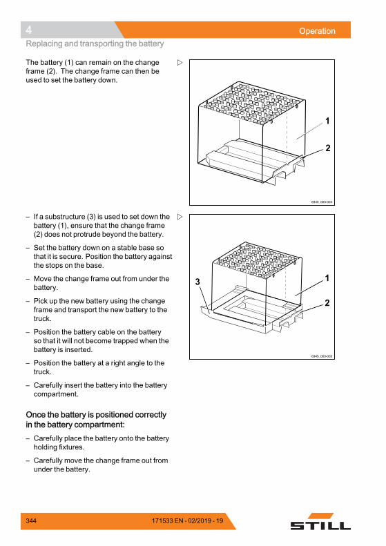
4 OperationReplacing and transporting the battery
The battery (1) can remain on the changeframe (2). The change frame can then beused to set the battery down.
– If a substructure (3) is used to set down thebattery (1), ensure that the change frame(2) does not protrude beyond the battery.
– Set the battery down on a stable base sothat it is secure. Position the battery againstthe stops on the base.
– Move the change frame out from under thebattery.
– Pick up the new battery using the changeframe and transport the new battery to thetruck.
– Position the battery cable on the batteryso that it will not become trapped when thebattery is inserted.
– Position the battery at a right angle to thetruck.
– Carefully insert the battery into the batterycompartment.
Once the battery is positioned correctlyin the battery compartment:– Carefully place the battery onto the batteryholding fixtures.
– Carefully move the change frame out fromunder the battery.
344 171533 EN - 02/2019 - 19
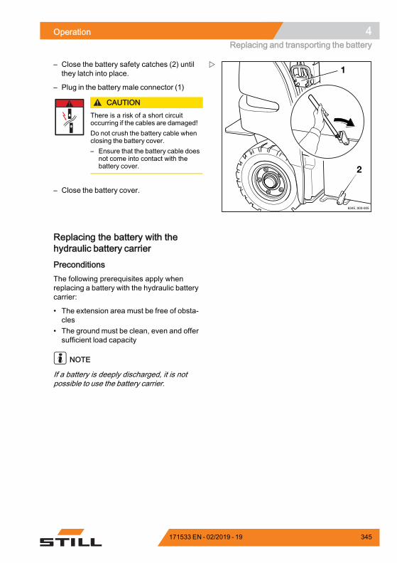
Operation 4Replacing and transporting the battery
– Close the battery safety catches (2) untilthey latch into place.
– Plug in the battery male connector (1)
CAUTIONThere is a risk of a short circuitoccurring if the cables are damaged!Do not crush the battery cable whenclosing the battery cover.– Ensure that the battery cable does
not come into contact with thebattery cover.
– Close the battery cover.
Replacing the battery with thehydraulic battery carrier
PreconditionsThe following prerequisites apply whenreplacing a battery with the hydraulic batterycarrier:
• The extension area must be free of obsta-cles
• The ground must be clean, even and offersufficient load capacity
NOTE
If a battery is deeply discharged, it is notpossible to use the battery carrier.
171533 EN - 02/2019 - 19 345
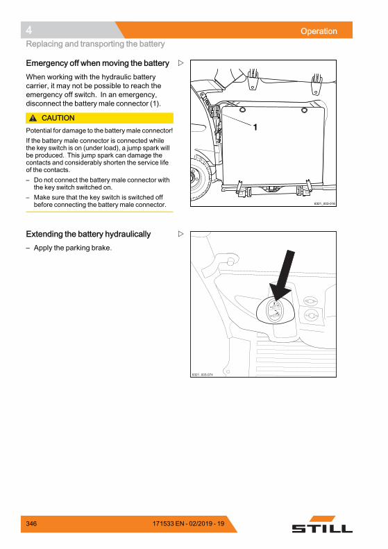
4 OperationReplacing and transporting the battery
1
6321_003-016
Emergency off when moving the batteryWhen working with the hydraulic batterycarrier, it may not be possible to reach theemergency off switch. In an emergency,disconnect the battery male connector (1).
CAUTIONPotential for damage to the battery male connector!If the battery male connector is connected whilethe key switch is on (under load), a jump spark willbe produced. This jump spark can damage thecontacts and considerably shorten the service lifeof the contacts.– Do not connect the battery male connector with
the key switch switched on.– Make sure that the key switch is switched off
before connecting the battery male connector.
6321_003-074
Extending the battery hydraulically– Apply the parking brake.
346 171533 EN - 02/2019 - 19
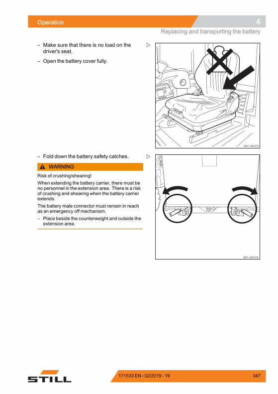
Operation 4Replacing and transporting the battery
6321_003-075
– Make sure that there is no load on thedriver's seat.
– Open the battery cover fully.
6321_003-076
– Fold down the battery safety catches.
WARNINGRisk of crushing/shearing!When extending the battery carrier, there must beno personnel in the extension area. There is a riskof crushing and shearing when the battery carrierextends.The battery male connector must remain in reachas an emergency off mechanism.– Place beside the counterweight and outside the
extension area.
171533 EN - 02/2019 - 19 347
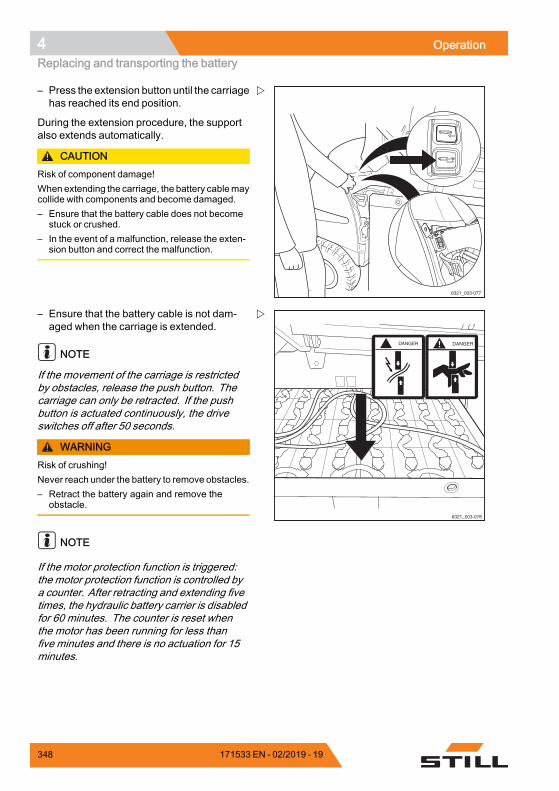
4 OperationReplacing and transporting the battery
6321_003-077
– Press the extension button until the carriagehas reached its end position.
During the extension procedure, the supportalso extends automatically.
CAUTIONRisk of component damage!When extending the carriage, the battery cablemaycollide with components and become damaged.– Ensure that the battery cable does not become
stuck or crushed.– In the event of a malfunction, release the exten-
sion button and correct the malfunction.
DANGER DANGER
6321_003-078
– Ensure that the battery cable is not dam-aged when the carriage is extended.
NOTE
If the movement of the carriage is restrictedby obstacles, release the push button. Thecarriage can only be retracted. If the pushbutton is actuated continuously, the driveswitches off after 50 seconds.
WARNINGRisk of crushing!Never reach under the battery to remove obstacles.– Retract the battery again and remove the
obstacle.
NOTE
If the motor protection function is triggered:the motor protection function is controlled bya counter. After retracting and extending fivetimes, the hydraulic battery carrier is disabledfor 60 minutes. The counter is reset whenthe motor has been running for less thanfive minutes and there is no actuation for 15minutes.
348 171533 EN - 02/2019 - 19
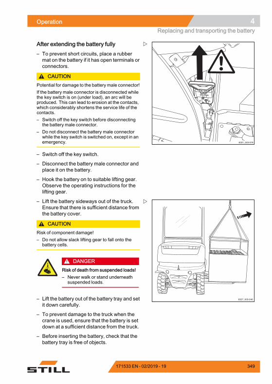
Operation 4Replacing and transporting the battery
6321_003-079
After extending the battery fully– To prevent short circuits, place a rubbermat on the battery if it has open terminals orconnectors.
CAUTIONPotential for damage to the battery male connector!If the battery male connector is disconnected whilethe key switch is on (under load), an arc will beproduced. This can lead to erosion at the contacts,which considerably shortens the service life of thecontacts.– Switch off the key switch before disconnecting
the battery male connector.– Do not disconnect the battery male connector
while the key switch is switched on, except in anemergency.
– Switch off the key switch.
– Disconnect the battery male connector andplace it on the battery.
– Hook the battery on to suitable lifting gear.Observe the operating instructions for thelifting gear.
6327_003-046
– Lift the battery sideways out of the truck.Ensure that there is sufficient distance fromthe battery cover.
CAUTIONRisk of component damage!– Do not allow slack lifting gear to fall onto the
battery cells.
DANGERRisk of death from suspended loads!– Never walk or stand underneath
suspended loads.
– Lift the battery out of the battery tray and setit down carefully.
– To prevent damage to the truck when thecrane is used, ensure that the battery is setdown at a sufficient distance from the truck.
– Before inserting the battery, check that thebattery tray is free of objects.
171533 EN - 02/2019 - 19 349
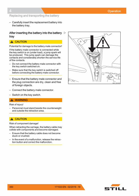
4 OperationReplacing and transporting the battery
– Carefully insert the replacement battery intothe battery tray.
6321_003-081
After inserting the battery into the batterytray
CAUTIONPotential for damage to the battery male connector!If the battery male connector is connected whilethe key switch is on (under load), a jump spark willbe produced. This jump spark can damage thecontacts and considerably shorten the service lifeof the contacts.– Do not connect the battery male connector with
the key switch switched on.– Make sure that the key switch is switched off
before connecting the battery male connector.
– Ensure that the battery male connector andthe plug connection are dry, clean and freeof foreign objects.
– Connect the battery male connector.
– Switch on the key switch.
WARNINGRisk of injury!– Personnel must stand beside the counterweight
and outside the retraction area.
CAUTIONRisk of component damage!When retracting the carriage, the battery cable maycollide with components and become damaged.– Ensure that the battery cable does not become
stuck or crushed.– In the event of a malfunction, release the retrac-
tion button and correct the malfunction.
350 171533 EN - 02/2019 - 19
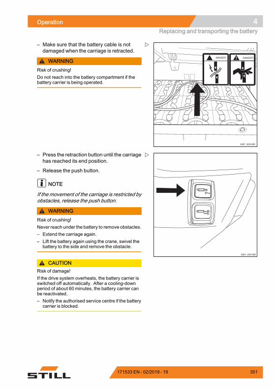
Operation 4Replacing and transporting the battery
DANGER DANGER
6321_003-083
– Make sure that the battery cable is notdamaged when the carriage is retracted.
WARNINGRisk of crushing!Do not reach into the battery compartment if thebattery carrier is being operated.
6321_003-082
– Press the retraction button until the carriagehas reached its end position.
– Release the push button.
NOTE
If the movement of the carriage is restricted byobstacles, release the push button.
WARNINGRisk of crushing!Never reach under the battery to remove obstacles.– Extend the carriage again.– Lift the battery again using the crane, swivel the
battery to the side and remove the obstacle.
CAUTIONRisk of damage!If the drive system overheats, the battery carrier isswitched off automatically. After a cooling-downperiod of about 60 minutes, the battery carrier canbe reactivated.– Notify the authorised service centre if the battery
carrier is blocked.
171533 EN - 02/2019 - 19 351
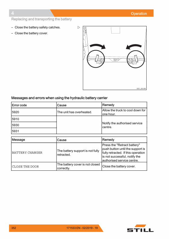
4 OperationReplacing and transporting the battery
6321_003-084
– Close the battery safety catches.
– Close the battery cover.
Messages and errors when using the hydraulic battery carrier
Error code Cause Remedy
5920 The unit has overheated. Allow the truck to cool down forone hour.
5910
5930
5931
Notify the authorised servicecentre.
Message Cause Remedy
BATTERY CHANGER The battery support is not fullyretracted.
Press the "Retract battery"push button until the support isfully retracted. If this operationis not successful, notify theauthorised service centre.
CLOSE THE DOORThe battery cover is not closedcorrectly. Close the battery cover.
.
352 171533 EN - 02/2019 - 19
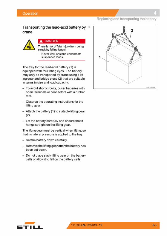
Operation 4Replacing and transporting the battery
6210_003-012
1
2Transporting the lead-acid battery bycrane
DANGERThere is risk of fatal injury from beingstruck by falling loads!– Never walk or stand underneath
suspended loads.
The tray for the lead-acid battery (1) isequipped with four lifting eyes. The batterymay only be transported by crane using a lift-ing gear and bridge piece (2) that are suitablein terms in size and load capacity.
– To avoid short circuits, cover batteries withopen terminals or connectors with a rubbermat.
– Observe the operating instructions for thelifting gear.
– Attach the battery (1) to suitable lifting gear(2).
– Lift the battery carefully and ensure that ithangs straight on the lifting gear.
The lifting gearmust be vertical when lifting, sothat no lateral pressure is applied to the tray.
– Set the battery down carefully.
– Remove the lifting gear after the battery hasbeen set down.
– Do not place slack lifting gear on the batterycells or allow it to fall on the battery cells.
171533 EN - 02/2019 - 19 353
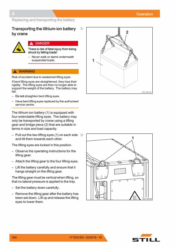
4 OperationReplacing and transporting the battery
6210_003-012
1
2Transporting the lithium-ion batteryby crane
DANGERThere is risk of fatal injury from beingstruck by falling loads!– Never walk or stand underneath
suspended loads.
WARNINGRisk of accident due to weakened lifting eyes.If bent lifting eyes are straightened, they lose theirrigidity. The lifting eyes are then no longer able tosupport the weight of the battery. The battery mayfall.– Do not straighten bent lifting eyes.
– Have bent lifting eyes replaced by the authorisedservice centre.
The lithium-ion battery (1) is equipped withfour extendable lifting eyes. The battery mayonly be transported by crane using a liftinggear and bridge piece (2) that are suitable interms in size and load capacity.
– Pull out the two lifting eyes (1) on each sideand tilt them towards each other.
The lifting eyes are locked in this position.
– Observe the operating instructions for thelifting gear.
– Attach the lifting gear to the four lifting eyes.
– Lift the battery carefully and ensure that ithangs straight on the lifting gear.
The lifting gearmust be vertical when lifting, sothat no lateral pressure is applied to the tray.
– Set the battery down carefully.
– Remove the lifting gear after the battery hasbeen set down. Lift up and release the liftingeyes to lower them.
354 171533 EN - 02/2019 - 19
Operation 4Cleaning the truck
Cleaning the truckCleaning the truck
WARNINGRisk of injury from falling off the truck!When climbing onto the truck, thereis a risk of getting stuck or slippingand falling. Use suitable equipment toreach higher points on the truck.– Use only the steps provided to
climb onto the truck.– Use equipment such as steplad-
ders or platforms to reach inacces-sible areas.
WARNINGRisk of fire due to flammable cleaningmaterials!Flammable cleaning materials can beignited by hot components.– Do not use any flammable cleaning
materials.
CAUTIONRisk of fire due to flammable materi-als!Deposits and solids can be ignited byhot components, e.g. drive units.– Remove deposits and solids.
CAUTIONRisk of damage to the battery male connector whendisconnecting!If the battery male connector is disconnected whilethe key switch is switched on under load, an arc willbe produced. The arc can damage the contacts andconsiderably shorten the service life of the contacts.– Switch off the key switch.– Only disconnect the battery male connector
while the key switch is switched off.
CAUTIONIf water penetrates the electrical system, there is arisk of short circuit!– Adhere strictly to the following steps.
171533 EN - 02/2019 - 19 355
4 OperationCleaning the truck
CAUTIONExcessive water pressure or water and steam thatare too hot can damage truck components.– Adhere strictly to the following steps.
CAUTIONAbrasive cleaning materials can damage the surfa-ces of components!Using abrasive cleaning materials that are unsuita-ble for plastics can cause plastic parts to dissolveor become brittle. The screen on the display-opera-ting unit could become cloudy.– Adhere strictly to the following steps.
– Park the truck safely.
– Switch off the key switch.
– Disconnect the battery male connector.
– Do not spray electric motors and otherelectrical components or their coversdirectly with water.
– Use only high-pressure cleaners with amaximum output power of up to 50 bar and85°C.
– If a high-pressure cleaner is used, maintaina distance of at least 20 cm between thenozzle and the object being cleaned.
– Do not aim the cleaning jet directly atadhesive labels or decal information.
– Remove all deposits and accumulationsof foreign materials in the vicinity of hotcomponents.
– Use only non-flammable fluids for cleaning.
– Note the manufacturer's guidelines forworking with cleaning materials.
– Clean plastics only with cleaning materialsintended for plastics.
– Note the manufacturer's guidelines forworking with cleaning materials.
– Clean the truck exterior using water-solublecleaning materials and water. Cleaningwith a water jet, a sponge or a cloth isrecommended.
– Clean all accessible areas.
356 171533 EN - 02/2019 - 19
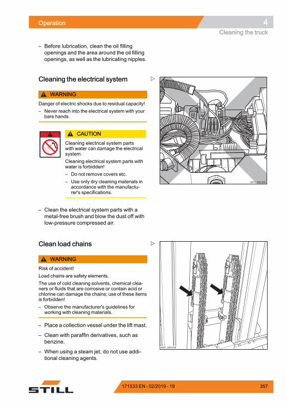
Operation 4Cleaning the truck
– Before lubrication, clean the oil fillingopenings and the area around the oil fillingopenings, as well as the lubricating nipples.
6210_600-005
Cleaning the electrical system
WARNINGDanger of electric shocks due to residual capacity!– Never reach into the electrical system with your
bare hands.
CAUTIONCleaning electrical system partswith water can damage the electricalsystem.Cleaning electrical system parts withwater is forbidden!– Do not remove covers etc.– Use only dry cleaning materials in
accordance with the manufactu-rer's specifications.
– Clean the electrical system parts with ametal-free brush and blow the dust off withlow-pressure compressed air.
6327_003-016
Clean load chains
WARNINGRisk of accident!Load chains are safety elements.The use of cold cleaning solvents, chemical clea-ners or fluids that are corrosive or contain acid orchlorine can damage the chains; use of these itemsis forbidden!– Observe the manufacturer's guidelines for
working with cleaning materials.
– Place a collection vessel under the lift mast.
– Clean with paraffin derivatives, such asbenzine.
– When using a steam jet, do not use addi-tional cleaning agents.
171533 EN - 02/2019 - 19 357
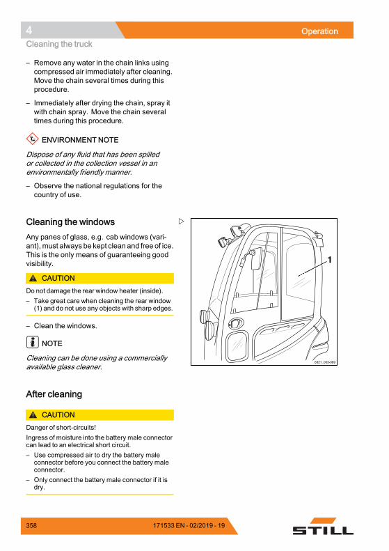
4 OperationCleaning the truck
– Remove any water in the chain links usingcompressed air immediately after cleaning.Move the chain several times during thisprocedure.
– Immediately after drying the chain, spray itwith chain spray. Move the chain severaltimes during this procedure.
ENVIRONMENT NOTE
Dispose of any fluid that has been spilledor collected in the collection vessel in anenvironmentally friendly manner.
– Observe the national regulations for thecountry of use.
6321_003-089
1
Cleaning the windowsAny panes of glass, e.g. cab windows (vari-ant), must always be kept clean and free of ice.This is the only means of guaranteeing goodvisibility.
CAUTIONDo not damage the rear window heater (inside).– Take great care when cleaning the rear window
(1) and do not use any objects with sharp edges.
– Clean the windows.
NOTE
Cleaning can be done using a commerciallyavailable glass cleaner.
After cleaning
CAUTIONDanger of short-circuits!Ingress of moisture into the battery male connectorcan lead to an electrical short circuit.– Use compressed air to dry the battery male
connector before you connect the battery maleconnector.
– Only connect the battery male connector if it isdry.
358 171533 EN - 02/2019 - 19
Operation 4Cleaning the truck
– Thoroughly dry the truck after wet cleaning,e.g. using compressed air.
– Apply a thin layer of oil or grease to alluncoated moving parts.
– Grease the truck.
– Lubricate the joints and controls.
– Lubricate the battery cover interlock.
– Check that the battery male connector isdry before you connect the battery maleconnector.
NOTE
Themore often the truck is cleaned, the morefrequently the truck must be lubricated.
171533 EN - 02/2019 - 19 359
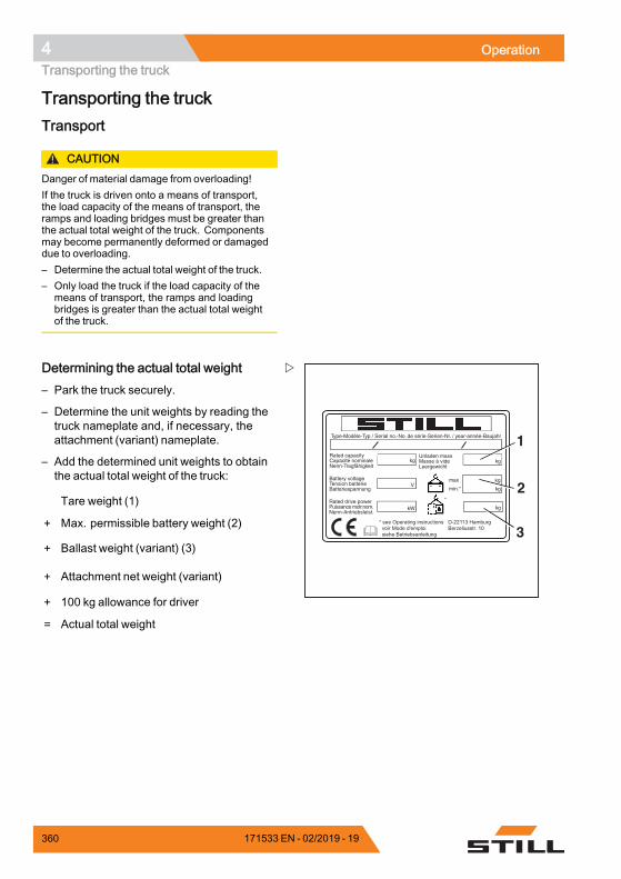
4 OperationTransporting the truck
Transporting the truckTransport
CAUTIONDanger of material damage from overloading!If the truck is driven onto a means of transport,the load capacity of the means of transport, theramps and loading bridges must be greater thanthe actual total weight of the truck. Componentsmay become permanently deformed or damageddue to overloading.– Determine the actual total weight of the truck.– Only load the truck if the load capacity of the
means of transport, the ramps and loadingbridges is greater than the actual total weightof the truck.
Type-Modèle-Typ / Serial no.-No. de série-Serien-Nr. / year-année-Baujahr
Rated capacityCapacité nominaleNenn-Tragfähigkeit
Battery voltageTension batterieBatteriespannung
Rated drive powerPuissance motr.nom.Nenn-Antriebsleist.
Unladen massMasse à videLeergewicht
max
min.*
kg kg
kg
kg
kgkW
V
*
* see Operating instructions voir Mode d'emploi siehe Betriebsanleitung
D-22113 HamburgBerzeliusstr. 10
1
3
2
Determining the actual total weight– Park the truck securely.
– Determine the unit weights by reading thetruck nameplate and, if necessary, theattachment (variant) nameplate.
– Add the determined unit weights to obtainthe actual total weight of the truck:
Tare weight (1)
+ Max. permissible battery weight (2)
+ Ballast weight (variant) (3)
+ Attachment net weight (variant)
+ 100 kg allowance for driver
= Actual total weight
360 171533 EN - 02/2019 - 19
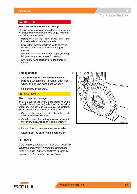
Operation 4Transporting the truck
DANGERRisk of accident from the truck crashing!Steering movements can cause the tail end to veeroff the loading bridge towards the edge. This maycause the truck to crash.– Before driving over a loading bridge, ensure that
it is installed and secured properly.– Ensure that the transport vehicle to be driven
onto has been sufficiently secured againstmoving.
– Maintain a safety distance from edges, loadingbridges, ramps, working platforms etc.
– Drive slowly and carefully onto the transportvehicle.
6210_001-012_V3
Setting chocks– Secure the truck from rolling away byplacing a wheel chock in front of each frontwheel and behind each back wheel (1).
– Park the truck securely.
CAUTIONRisk of component damage!If you remove the battery male connector when thekey switch is switched on (under load), an arcwill beproduced. This can lead to erosion at the contacts,which considerably shortens their service life.– Switch off the key switch before the battery male
connector is disconnected.– Only disconnect the battery male connector with
the key switch switched on in an emergency.
– Ensure that the key switch is switched off.
– Disconnect the battery male connector.
NOTE
If the electric parking brake (variant) cannot betriggered electrically, it must be applied ma-nually; see the chapter entitled "Emergencyoperation of the electric parking brake".
171533 EN - 02/2019 - 19 361
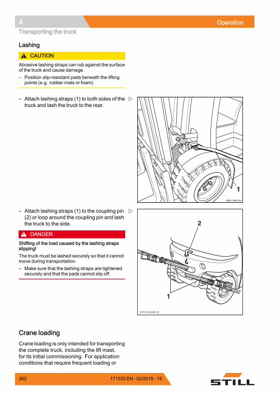
4 OperationTransporting the truck
Lashing
CAUTIONAbrasive lashing straps can rub against the surfaceof the truck and cause damage.– Position slip-resistant pads beneath the lifting
points (e.g. rubber mats or foam).
6321_003-104
1
– Attach lashing straps (1) to both sides of thetruck and lash the truck to the rear.
6210_003-048_V2
2
1
– Attach lashing straps (1) to the coupling pin(2) or loop around the coupling pin and lashthe truck to the side.
DANGERShifting of the load caused by the lashing strapsslipping!The truck must be lashed securely so that it cannotmove during transportation.– Make sure that the lashing straps are tightened
securely and that the pads cannot slip off.
Crane loadingCrane loading is only intended for transportingthe complete truck, including the lift mast,for its initial commissioning. For applicationconditions that require frequent loading or
362 171533 EN - 02/2019 - 19
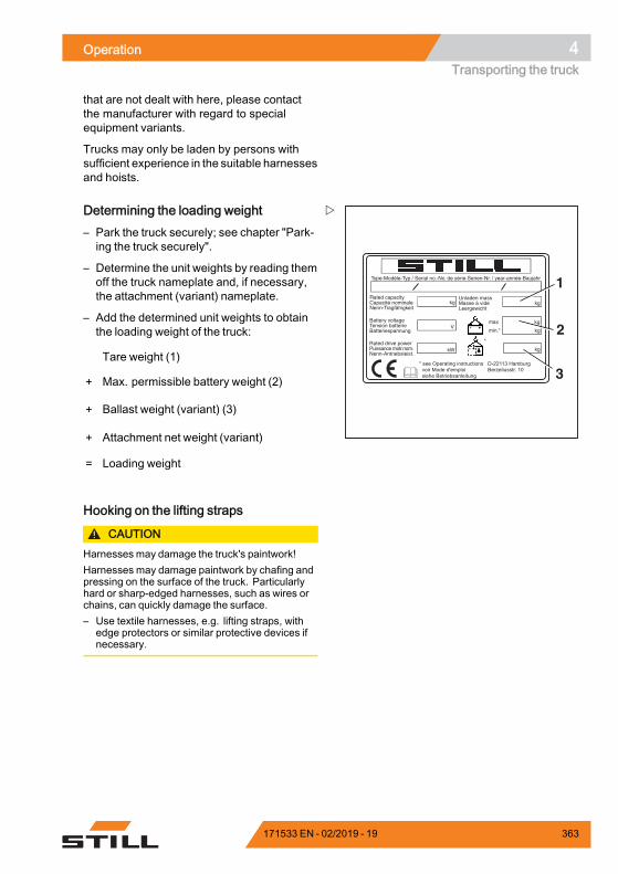
Operation 4Transporting the truck
that are not dealt with here, please contactthe manufacturer with regard to specialequipment variants.
Trucks may only be laden by persons withsufficient experience in the suitable harnessesand hoists.
Type-Modèle-Typ / Serial no.-No. de série-Serien-Nr. / year-année-Baujahr
Rated capacityCapacité nominaleNenn-Tragfähigkeit
Battery voltageTension batterieBatteriespannung
Rated drive powerPuissance motr.nom.Nenn-Antriebsleist.
Unladen massMasse à videLeergewicht
max
min.*
kg kg
kg
kg
kgkW
V
*
* see Operating instructions voir Mode d'emploi siehe Betriebsanleitung
D-22113 HamburgBerzeliusstr. 10
1
3
2
Determining the loading weight– Park the truck securely; see chapter "Park-ing the truck securely".
– Determine the unit weights by reading themoff the truck nameplate and, if necessary,the attachment (variant) nameplate.
– Add the determined unit weights to obtainthe loading weight of the truck:
Tare weight (1)
+ Max. permissible battery weight (2)
+ Ballast weight (variant) (3)
+ Attachment net weight (variant)
= Loading weight.
Hooking on the lifting straps
CAUTIONHarnesses may damage the truck's paintwork!Harnesses may damage paintwork by chafing andpressing on the surface of the truck. Particularlyhard or sharp-edged harnesses, such as wires orchains, can quickly damage the surface.– Use textile harnesses, e.g. lifting straps, with
edge protectors or similar protective devices ifnecessary.
171533 EN - 02/2019 - 19 363
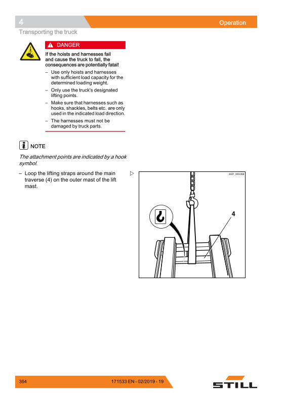
4 OperationTransporting the truck
DANGERIf the hoists and harnesses failand cause the truck to fall, theconsequences are potentially fatal!– Use only hoists and harnesses
with sufficient load capacity for thedetermined loading weight.
– Only use the truck's designatedlifting points.
– Make sure that harnesses such ashooks, shackles, belts etc. are onlyused in the indicated load direction.
– The harnesses must not bedamaged by truck parts.
NOTE
The attachment points are indicated by a hooksymbol.
4
6321_003-069– Loop the lifting straps around the maintraverse (4) on the outer mast of the liftmast.
364 171533 EN - 02/2019 - 19
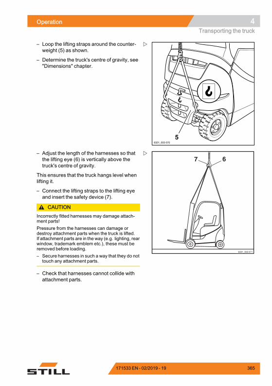
Operation 4Transporting the truck
6321_003-070
5
– Loop the lifting straps around the counter-weight (5) as shown.
– Determine the truck's centre of gravity, see"Dimensions" chapter.
6321_003-071
7 6– Adjust the length of the harnesses so thatthe lifting eye (6) is vertically above thetruck's centre of gravity.
This ensures that the truck hangs level whenlifting it.
– Connect the lifting straps to the lifting eyeand insert the safety device (7).
CAUTIONIncorrectly fitted harnesses may damage attach-ment parts!Pressure from the harnesses can damage ordestroy attachment parts when the truck is lifted.If attachment parts are in the way (e.g. lighting, rearwindow, trademark emblem etc.), these must beremoved before loading.– Secure harnesses in such a way that they do not
touch any attachment parts.
– Check that harnesses cannot collide withattachment parts.
171533 EN - 02/2019 - 19 365
4 OperationDecommissioning
Loading the truck
DANGERIf the raised truck swings in anuncontrolled fashion, it may crushpeople. There is a risk to life!– Never walk or stand underneath
suspended loads.– Do not allow the truck to bump into
anything whilst it is being lifted, orallow it to move in an uncontrolledway.
– If necessary, hold the truck usingguide ropes.
– Carefully lift the truck and set it down at theintended location.
DecommissioningDecommissioning and storing thetruck
CAUTIONComponent damage through incorrect storage!Improper storage or decommissioning for a periodof more than two months can result in corrosiondamage to the truck. If the truck is parked in an am-bient temperature of below -10°C for an extendedperiod, the batteries will cool down. The electrolytemay freeze and damage the batteries.– Store the truck in a dry, clean, frost-free and
well-ventilated environment.– Implement the following measures before
decommissioning.
Measures to be implemented beforedecommissioning– Clean the truck thoroughly, see the chapterentitled "Cleaning the truck".
– Lift the fork carriage to the stop severaltimes.
– Tilt the lift mast forwards and backwardsseveral times and, if fitted, move the attach-ment repeatedly.
366 171533 EN - 02/2019 - 19
Operation 4Decommissioning
– To relieve the strain on the load chains,lower the fork onto a suitable supportingsurface, e.g. a pallet.
– Check the hydraulic oil level. Top the oil upif necessary.
– Apply a thin layer of oil or grease to alluncoated moving parts.
– Lubricate the truck.
– Lubricate the joints and controls.
– Lubricate the slide elements and guides ofthe hydraulic battery carrier (variant); seethe section entitled "Lubricating the slideelements" in the chapter entitled "1000-hourmaintenance/annual maintenance".
– Lubricate the catch rail of the hydraulicbattery carrier (variant); see the sectionentitled "Oiling the catch rails" in the chapterentitled "1000-hour maintenance/annualmaintenance".
– Lubricate the battery interlock and thebattery cover; see the section entitled"Checking the battery interlock and batterycover" in the chapter entitled "Remainingready for operation".
CAUTIONRisk of component damage!If you remove the battery male connector with thekey switch switched on (under load), an arc will beproduced. This can cause the contacts to erode,which considerably shortens their service life.– Switch off the key switch before disconnecting
the battery male connector.– Do not disconnect the battery male connector
while the key switch is switched on, except in anemergency.
– Disconnect the battery male connector.
– Check the battery condition, acid level andacid density.
– Service the battery.
NOTE
Store only fully charged batteries.
171533 EN - 02/2019 - 19 367
4 OperationDecommissioning
– Apply a suitable contact spray to all exposedelectrical contacts.
CAUTIONTyre deformation as a result of continuous loadingon one side!Have the truck raised and jacked up by the autho-rised service centre so that all wheels are off theground. This prevents permanent deformation ofthe tyres.– Only have the truck raised and jacked up by the
authorised service centre.
CAUTIONRisk of damage from corrosion due to condensationon the truck!Many plastic films and synthetic materials arewatertight. Condensation water on the truck cannotescape through these covers.– Do not use plastic film as this facilitates the
formation of condensation water.– Cover with vapour-permeable material, e.g.
cotton.
– Cover the truck to protect it from dust.
– If the truck is to be shut down for evenlonger periods, contact the authorisedservice centre to find out about additionalmeasures.
Returning to service after decommis-sioningIf the truck has been decommissioned forlonger than six months, it must be carefullychecked before being re-commissioned. Aswith the annual safety inspection, this checkshould also include all safety-related aspectsof the truck.
– Clean the truck thoroughly, see the chapterentitled "Cleaning the truck".
– Lubricate the joints and controls.
– Lubricate the slide elements and guides ofthe hydraulic battery carrier (variant); seethe section entitled "Lubricating the slideelements" in the chapter entitled "1000-hourmaintenance/annual maintenance".
368 171533 EN - 02/2019 - 19
Operation 4Decommissioning
– Lubricate the catch rail of the hydraulicbattery carrier (variant); see the sectionentitled "Oiling the catch rails" in the chapterentitled "1000-hour maintenance/annualmaintenance".
– Check the battery condition, acid level andacid density.
– Check the hydraulic oil for condensationwater. Change the hydraulic oil if neces-sary.
– Carry out the checks and tasks that are to beperformed before the first commissioning.
– Perform "visual inspections and functionchecking".
The following points must be checked inparticular:• Drive, control, steering• Brakes (service brake, parking brake)• Lifting system (lifting accessories, loadchains, mounting)
NOTE
For further information, see the workshopmanual for the truck or contact the authorisedservice centre.
171533 EN - 02/2019 - 19 369

4 OperationDecommissioning
370 171533 EN - 02/2019 - 19

5
Maintenance

5 MaintenanceSafety regulations for maintenance
Safety regulations for maintenanceGeneral informationTo prevent accidents during maintenance andrepair work, all necessary safety measuresmust be taken, e.g.:
– Apply the parking brake.
– Turn off the key switch and remove the key.
– Disconnect the battery male connector.
– Ensure that the truck cannot move uninten-tionally or start up inadvertently.
– If required, have the truck jacked up by theauthorised service centre.
– Have the raised fork carriage or the ex-tended lift mast secured against accidentallowering by the authorised service centre.
– Insert an appropriately sized wooden beamas an abutment between the lift mast andthe cab, and secure the lift mast to preventit tilting backwards unintentionally.
– Observe the maximum lift height of the liftmast, and compare the dimensions fromthe technical data with the dimensions ofthe hall into which the truck is to be driven.These steps are taken to prevent a collisionwith the ceiling of the hall and to avoid anydamage caused as a result.
Working on the hydraulic equipmentThe hydraulic systemmust be depressurisedprior to all work on the system.
Working on the electrical equipmentWork may only be performed on the electricalequipment of the truck when it is in a voltage-free state. Function checks, inspectionsand adjustments on energised parts mustonly be performed by trained and authorisedpersons, taking the necessary precautionsinto account. Rings, metal bracelets etc.must be removed before working on electriccomponents.
372 171533 EN - 02/2019 - 19
Maintenance 5Safety regulations for maintenance
To prevent damage to electronic systemswith electronic components, such as anelectronic driving regulator or lift control, thesecomponents must be removed from the truckprior to the start of electric welding.
Work on the electrical system (e.g. connectinga radio, additional headlights etc.) is onlypermitted with approval from the authorisedservice centre.
Safety devicesAfter maintenance and repair work, all safetydevices must be reinstalled and tested foroperational reliability.
Set valuesThe device-dependent set values must beobserved when making repairs and whenchanging hydraulic and electrical compo-nents. These are listed in the appropriatesections.
Lifting and jacking up
DANGERThere is a risk to life if the truck tips over!If not raised and jacked up properly, the truck maytip over and fall off. Only the hoists specified in theworkshop manual for this truck are allowed and aretested for the necessary safety and load capacity.– Only have the truck raised and jacked up by the
authorised service centre.– Only jack the truck up at the points specified in
the workshop manual.
The truck must be raised and jacked up forvarious types of maintenance work. Theauthorised service centre must be informedthat this is to take place. Safe handling ofthe truck and the corresponding hoists isdescribed in the truck's workshop manual.
171533 EN - 02/2019 - 19 373
5 MaintenanceSafety regulations for maintenance
Working at the front of the truck
DANGERRisk of accident!If the lift mast or fork carriage is raised, no workmay be performed on the lift mast or at the front ofthe truck unless the following safety measures areobserved.– When securing, only use chains with sufficient
load-bearing capacity.– Contact the authorised service centre.
CAUTIONPossibility of damage to the ceiling!– Note the maximum lift height of the lift mast.
Securing the lift mast against tiltingbackwardsA hardwood beam with a cross-section of120 x 120 mm is required. The length ofthe hardwood beam must approximatelycorrespond to the width of the fork carriage(b3). To avoid impact injuries, the hardwoodbeam must not protrude beyond the outercontour of the truck. A maximum lengthmatching the total width (b1) of the truck isrecommended.
– Obtain the dimensions (b1) and (b3) fromthe corresponding VDI datasheet.
374 171533 EN - 02/2019 - 19
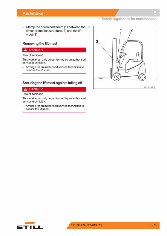
Maintenance 5Safety regulations for maintenance
1 2
3
6210_001-030_V3
– Clamp the hardwood beam (1) between thedriver protection structure (2) and the liftmast (3).
Removing the lift mast
DANGERRisk of accident!This work must only be performed by an authorisedservice technician.– Arrange for an authorised service technician to
remove the lift mast.
Securing the lift mast against falling off
DANGERRisk of accident!This work must only be performed by an authorisedservice technician.– Arrange for an authorised service technician to
secure the lift mast.
171533 EN - 02/2019 - 19 375
5 MaintenanceGeneral maintenance information
General maintenance informationPersonnel qualificationsOnly qualified and authorised personnel areallowed to perform maintenance work. Reg-ular safety checks and checks after unusualincidents must be performed by a competentperson. The competent person must conducttheir evaluation and assessment from a safetystandpoint, unaffected by operational andeconomic conditions. The competent personmust have sufficient knowledge and experi-ence to be able to assess the condition of atruck and the effectiveness of the protectivedevices in accordance with technical conven-tions and the principles for testing trucks.
Maintenance personnel for batteriesBatteries may only be charged, serviced, andreplaced by personnel who have receivedappropriate training in accordance with theinstructions from the manufacturers of thebattery, battery charger and truck.
– Follow the handling instructions for thebattery and the operating instructions forthe battery charger.
Maintenance work without specialqualificationsSimple maintenance work, such as checkingthe hydraulic oil level, may be carried out byuntrained personnel. A qualification suchas those held by a competent person is notrequired to carry out this work. The requiredtasks are described in the chapter entitled"Remaining ready for operation".
Information for carrying out mainte-nanceThis section contains all information requiredto determine when the truck needs mainte-nance. Carry out maintenance work within thetime limits according to the hour meter andusing the following maintenance check lists.This is the only way to ensure that the truckremains ready for operation and provides op-
376 171533 EN - 02/2019 - 19
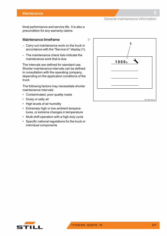
Maintenance 5General maintenance information
timal performance and service life. It is also aprecondition for any warranty claims.
7312_003-156_V2
1Maintenance timeframe– Carry out maintenance work on the truck inaccordance with the "Service in" display (1).
– The maintenance check lists indicate themaintenance work that is due.
The intervals are defined for standard use.Shorter maintenance intervals can be definedin consultation with the operating company,depending on the application conditions of thetruck.
The following factors may necessitate shortermaintenance intervals:• Contaminated, poor quality roads• Dusty or salty air• High levels of air humidity• Extremely high or low ambient tempera-tures, or extreme changes in temperature
• Multi-shift operation with a high duty cycle• Specific national regulations for the truck orindividual components
171533 EN - 02/2019 - 19 377

5 MaintenanceGeneral maintenance information
378 171533 EN - 02/2019 - 19
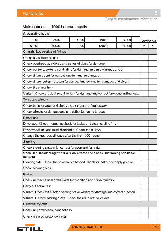
Maintenance 5General maintenance information
Maintenance— 1000 hours/annuallyAt operating hours
1000 2000 4000 5000 7000 Carried out8000 10000 11000 13000 14000
Chassis, bodywork and fittings
Check chassis for cracks
Check overhead guard/cab and panes of glass for damage
Check controls, switches and joints for damage, and apply grease and oil
Check driver's seat for correct function and for damage
Check driver restraint system for correct function and for damage, and clean.
Check the signal horn
Variant: Check the dual-pedal variant for damage and correct function, and lubricate
Tyres and wheels
Check tyres for wear and check the air pressure if necessary
Check wheels for damage and check the tightening torques
Power unit
Drive axle: Check mounting, check for leaks, and clean cooling fins
Drive wheel unit and multi-disc brake: Check the oil level
Change the gearbox oil (once after the first 1000 hours)
Steering
Check steering system for correct function and for leaksCheck that the steering wheel is firmly attached and check the turning handle fordamageSteering axle: Check that it is firmly attached, check for leaks, and apply grease
Check steering stop
Brake
Check all mechanical brake parts for condition and correct function
Carry out brake test
Variant: Check the electric parking brake variant for damage and correct function
Variant: Electric parking brake: Check the relubrication device
Electrical system
Check all power cable connections
Check main contactor contacts
171533 EN - 02/2019 - 19 379
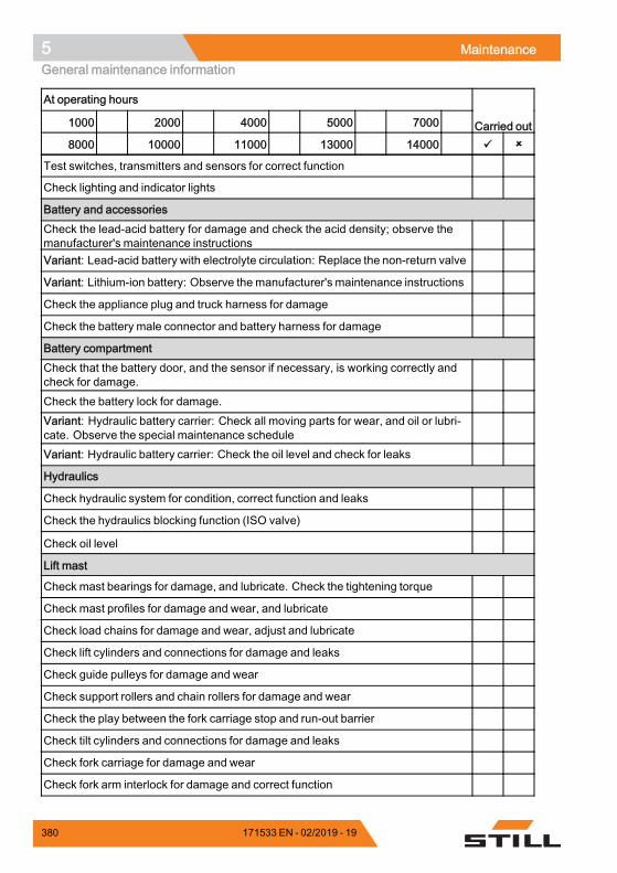
5 MaintenanceGeneral maintenance information
At operating hours
1000 2000 4000 5000 7000 Carried out8000 10000 11000 13000 14000
Test switches, transmitters and sensors for correct function
Check lighting and indicator lights
Battery and accessoriesCheck the lead-acid battery for damage and check the acid density; observe themanufacturer's maintenance instructionsVariant: Lead-acid battery with electrolyte circulation: Replace the non-return valve
Variant: Lithium-ion battery: Observe the manufacturer's maintenance instructions
Check the appliance plug and truck harness for damage
Check the battery male connector and battery harness for damage
Battery compartmentCheck that the battery door, and the sensor if necessary, is working correctly andcheck for damage.Check the battery lock for damage.Variant: Hydraulic battery carrier: Check all moving parts for wear, and oil or lubri-cate. Observe the special maintenance scheduleVariant: Hydraulic battery carrier: Check the oil level and check for leaks
Hydraulics
Check hydraulic system for condition, correct function and leaks
Check the hydraulics blocking function (ISO valve)
Check oil level
Lift mast
Check mast bearings for damage, and lubricate. Check the tightening torque
Check mast profiles for damage and wear, and lubricate
Check load chains for damage and wear, adjust and lubricate
Check lift cylinders and connections for damage and leaks
Check guide pulleys for damage and wear
Check support rollers and chain rollers for damage and wear
Check the play between the fork carriage stop and run-out barrier
Check tilt cylinders and connections for damage and leaks
Check fork carriage for damage and wear
Check fork arm interlock for damage and correct function
380 171533 EN - 02/2019 - 19
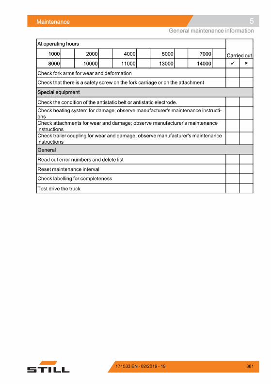
Maintenance 5General maintenance information
At operating hours
1000 2000 4000 5000 7000 Carried out8000 10000 11000 13000 14000
Check fork arms for wear and deformation
Check that there is a safety screw on the fork carriage or on the attachment
Special equipment
Check the condition of the antistatic belt or antistatic electrode.Check heating system for damage; observe manufacturer's maintenance instructi-onsCheck attachments for wear and damage; observe manufacturer's maintenanceinstructionsCheck trailer coupling for wear and damage; observe manufacturer's maintenanceinstructionsGeneral
Read out error numbers and delete list
Reset maintenance interval
Check labelling for completeness
Test drive the truck
171533 EN - 02/2019 - 19 381

5 MaintenanceGeneral maintenance information
382 171533 EN - 02/2019 - 19
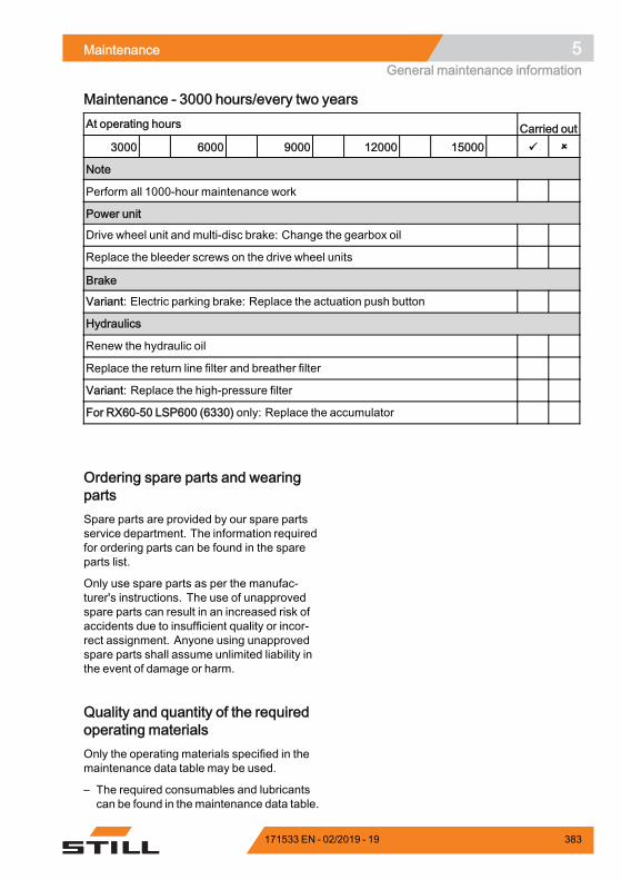
Maintenance 5General maintenance information
Maintenance - 3000 hours/every two yearsAt operating hours Carried out
3000 6000 9000 12000 15000
Note
Perform all 1000-hour maintenance work
Power unit
Drive wheel unit and multi-disc brake: Change the gearbox oil
Replace the bleeder screws on the drive wheel units
Brake
Variant: Electric parking brake: Replace the actuation push button
Hydraulics
Renew the hydraulic oil
Replace the return line filter and breather filter
Variant: Replace the high-pressure filter
For RX60-50 LSP600 (6330) only: Replace the accumulator
Ordering spare parts and wearingpartsSpare parts are provided by our spare partsservice department. The information requiredfor ordering parts can be found in the spareparts list.
Only use spare parts as per the manufac-turer's instructions. The use of unapprovedspare parts can result in an increased risk ofaccidents due to insufficient quality or incor-rect assignment. Anyone using unapprovedspare parts shall assume unlimited liability inthe event of damage or harm.
Quality and quantity of the requiredoperating materialsOnly the operating materials specified in themaintenance data table may be used.
– The required consumables and lubricantscan be found in themaintenance data table.
171533 EN - 02/2019 - 19 383
5 MaintenanceGeneral maintenance information
Oil and grease types of a different qualitymust not be mixed. This negatively affectsthe lubricity. If a change between differentmanufacturers cannot be avoided, drain theold oil thoroughly.
Before carrying out lubricating work, filterchanges or any work on the hydraulic system,carefully clean the area around the partinvolved.
When topping up working materials, use onlyclean containers!
384 171533 EN - 02/2019 - 19
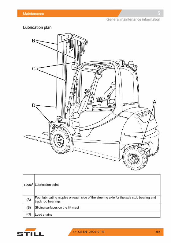
Maintenance 5General maintenance information
Lubrication plan
Code1 Lubrication point
(A) Four lubricating nipples on each side of the steering axle for the axle stub bearing andtrack rod bearings
(B) Sliding surfaces on the lift mast
(C) Load chains
171533 EN - 02/2019 - 19 385
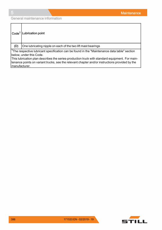
5 MaintenanceGeneral maintenance information
Code1 Lubrication point
(D) One lubricating nipple on each of the two lift mast bearings1The respective lubricant specification can be found in the "Maintenance data table" sectionbelow, under this Code.This lubrication plan describes the series-production truck with standard equipment. For main-tenance points on variant trucks, see the relevant chapter and/or instructions provided by themanufacturer.
.
386 171533 EN - 02/2019 - 19
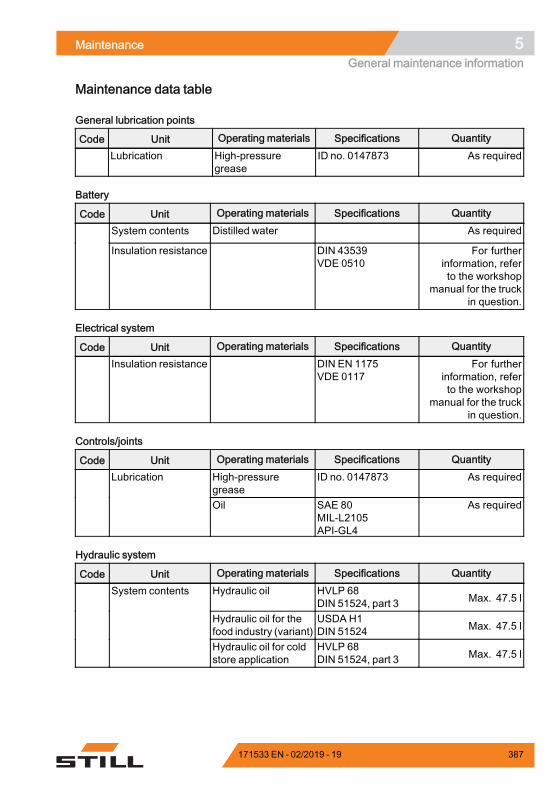
Maintenance 5General maintenance information
Maintenance data table
General lubrication points
Code Unit Operating materials Specifications QuantityLubrication High-pressure
greaseID no. 0147873 As required
Battery
Code Unit Operating materials Specifications QuantitySystem contents Distilled water As required
Insulation resistance DIN 43539VDE 0510
For furtherinformation, referto the workshop
manual for the truckin question.
Electrical system
Code Unit Operating materials Specifications QuantityInsulation resistance DIN EN 1175
VDE 0117For further
information, referto the workshop
manual for the truckin question.
Controls/joints
Code Unit Operating materials Specifications QuantityHigh-pressuregrease
ID no. 0147873 As requiredLubrication
Oil SAE 80MIL-L2105API-GL4
As required
Hydraulic system
Code Unit Operating materials Specifications QuantityHydraulic oil HVLP 68
DIN 51524, part 3 Max. 47.5 l
Hydraulic oil for thefood industry (variant)
USDA H1DIN 51524 Max. 47.5 l
System contents
Hydraulic oil for coldstore application
HVLP 68DIN 51524, part 3 Max. 47.5 l
171533 EN - 02/2019 - 19 387
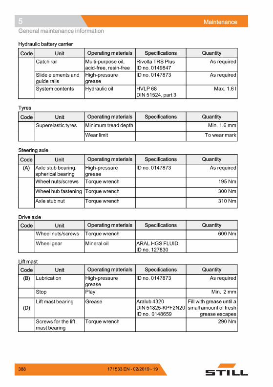
5 MaintenanceGeneral maintenance information
Hydraulic battery carrier
Code Unit Operating materials Specifications QuantityCatch rail Multi-purpose oil,
acid-free, resin-freeRivolta TRS PlusID no. 0149847
As required
Slide elements andguide rails
High-pressuregrease
ID no. 0147873 As required
System contents Hydraulic oil HVLP 68DIN 51524, part 3
Max. 1.6 l
Tyres
Code Unit Operating materials Specifications QuantityMinimum tread depth Min. 1.6 mmSuperelastic tyres
Wear limit To wear mark
Steering axle
Code Unit Operating materials Specifications Quantity(A) Axle stub bearing,
spherical bearingHigh-pressuregrease
ID no. 0147873 As required
Wheel nuts/screws Torque wrench 195 Nm
Wheel hub fastening Torque wrench 300 Nm
Axle stub nut Torque wrench 310 Nm
Drive axleCode Unit Operating materials Specifications Quantity
Wheel nuts/screws Torque wrench 600 Nm
Wheel gear Mineral oil ARAL HGS FLUIDID no. 127830
Lift mastCode Unit Operating materials Specifications Quantity(B) Lubrication High-pressure
greaseID no. 0147873 As required
Stop Play Min. 2 mm
(D)Lift mast bearing Grease Aralub 4320
DIN 51825-KPF2N20ID no. 0148659
Fill with grease until asmall amount of fresh
grease escapesScrews for the liftmast bearing
Torque wrench 290 Nm
388 171533 EN - 02/2019 - 19
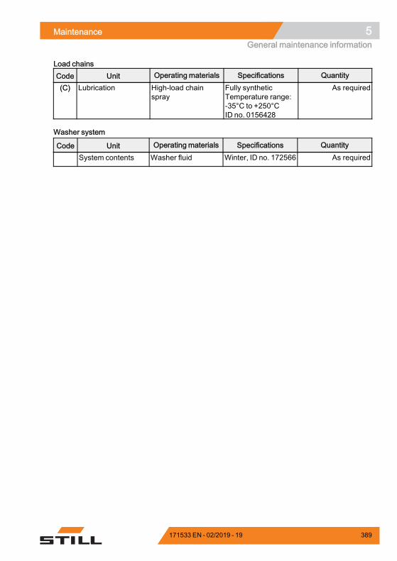
Maintenance 5General maintenance information
Load chainsCode Unit Operating materials Specifications Quantity(C) Lubrication High-load chain
sprayFully syntheticTemperature range:-35°C to +250°CID no. 0156428
As required
Washer system
Code Unit Operating materials Specifications QuantitySystem contents Washer fluid Winter, ID no. 172566 As required
.
171533 EN - 02/2019 - 19 389
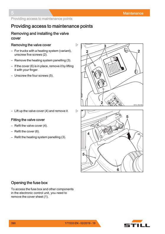
5 MaintenanceProviding access to maintenance points
Providing access to maintenance pointsRemoving and installing the valvecover
2
223
6210_762-002
Removing the valve cover– For trucks with a heating system (variant),unscrew five screws (2).
– Remove the heating system panelling (3).
– If the cover (6) is in place, remove it by liftingit with your finger.
– Unscrew the four screws (5).
5
5
6
4
– Lift up the valve cover (4) and remove it.
Fitting the valve cover– Refit the valve cover (4).
– Refit the cover (6).
– Refit the heating system panelling (3).
Opening the fuse boxTo access the fuse box and other componentsin the electronic control unit, you need toremove the cover sheet (1).
390 171533 EN - 02/2019 - 19
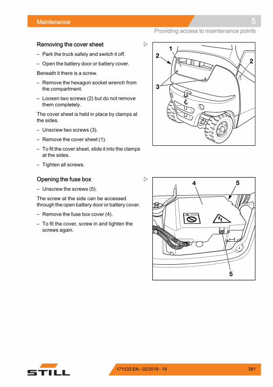
Maintenance 5Providing access to maintenance points
22
1
3
Removing the cover sheet– Park the truck safely and switch it off.
– Open the battery door or battery cover.
Beneath it there is a screw.
– Remove the hexagon socket wrench fromthe compartment.
– Loosen two screws (2) but do not removethem completely.
The cover sheet is held in place by clamps atthe sides.
– Unscrew two screws (3).
– Remove the cover sheet (1).
– To fit the cover sheet, slide it into the clampsat the sides.
– Tighten all screws.
4
5
5Opening the fuse box– Unscrew the screws (5).
The screw at the side can be accessedthrough the open battery door or battery cover.
– Remove the fuse box cover (4).
– To fit the cover, screw in and tighten thescrews again.
171533 EN - 02/2019 - 19 391
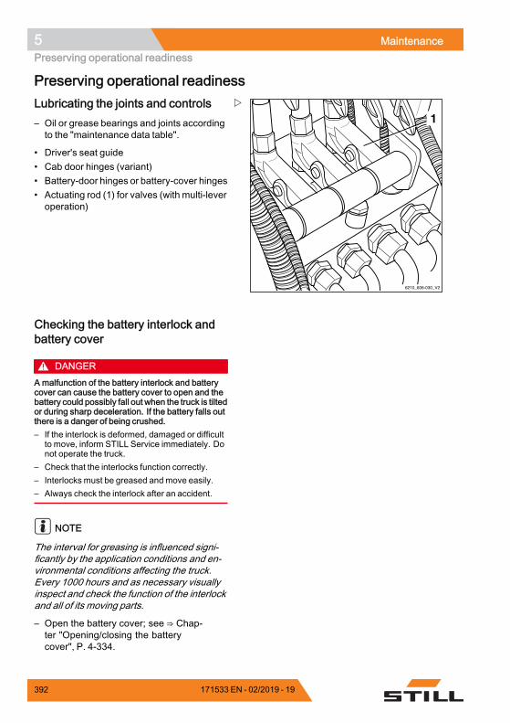
5 MaintenancePreserving operational readiness
Preserving operational readiness
6210_606-030_V2
1Lubricating the joints and controls– Oil or grease bearings and joints accordingto the "maintenance data table".
• Driver's seat guide• Cab door hinges (variant)• Battery-door hinges or battery-cover hinges• Actuating rod (1) for valves (with multi-leveroperation)
Checking the battery interlock andbattery cover
DANGERAmalfunction of the battery interlock and batterycover can cause the battery cover to open and thebattery could possibly fall out when the truck is tiltedor during sharp deceleration. If the battery falls outthere is a danger of being crushed.– If the interlock is deformed, damaged or difficult
to move, inform STILL Service immediately. Donot operate the truck.
– Check that the interlocks function correctly.– Interlocks must be greased and move easily.– Always check the interlock after an accident.
NOTE
The interval for greasing is influenced signi-ficantly by the application conditions and en-vironmental conditions affecting the truck.Every 1000 hours and as necessary visuallyinspect and check the function of the interlockand all of its moving parts.
– Open the battery cover; see ⇒ Chap-ter "Opening/closing the batterycover", P. 4-334.
392 171533 EN - 02/2019 - 19
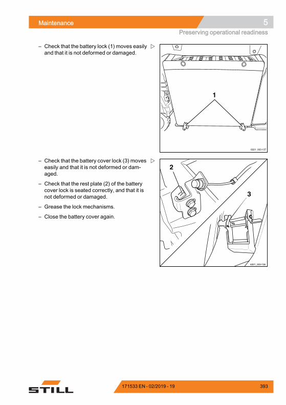
Maintenance 5Preserving operational readiness
6321_003-137
1
– Check that the battery lock (1) moves easilyand that it is not deformed or damaged.
6321_003-136
2
3
– Check that the battery cover lock (3) moveseasily and that it is not deformed or dam-aged.
– Check that the rest plate (2) of the batterycover lock is seated correctly, and that it isnot deformed or damaged.
– Grease the lock mechanisms.
– Close the battery cover again.
171533 EN - 02/2019 - 19 393
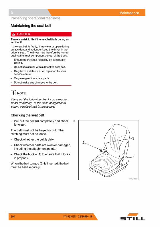
5 MaintenancePreserving operational readiness
Maintaining the seat belt
DANGERThere is a risk to life if the seat belt fails during anaccident!If the seat belt is faulty, it may tear or open duringan accident and no longer keep the driver in thedriver's seat. The driver may therefore be hurledagainst the truck components or out of the truck.– Ensure operational reliability by continually
testing.– Do not use a truck with a defective seat belt.– Only have a defective belt replaced by your
service centre.– Only use genuine spare parts.– Do not make any changes to the belt.
NOTE
Carry out the following checks on a regularbasis (monthly). In the case of significantstrain, a daily check is necessary.
Checking the seat belt
6327_342-009
1
23
– Pull out the belt (3) completely and checkfor wear.
The belt must not be frayed or cut. Thestitching must not be loose.
– Check whether the belt is dirty.
– Check whether parts are worn or damaged,including the attachment points.
– Check the buckle (1) to ensure that it locksin properly.
When the belt tongue (2) is inserted, the beltmust be held securely.
394 171533 EN - 02/2019 - 19
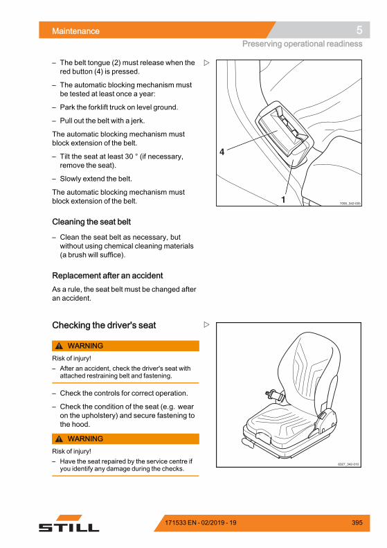
Maintenance 5Preserving operational readiness
7090_342-0051
4
– The belt tongue (2) must release when thered button (4) is pressed.
– The automatic blocking mechanism mustbe tested at least once a year:
– Park the forklift truck on level ground.
– Pull out the belt with a jerk.
The automatic blocking mechanism mustblock extension of the belt.
– Tilt the seat at least 30 ° (if necessary,remove the seat).
– Slowly extend the belt.
The automatic blocking mechanism mustblock extension of the belt.
Cleaning the seat belt
– Clean the seat belt as necessary, butwithout using chemical cleaning materials(a brush will suffice).
Replacement after an accidentAs a rule, the seat belt must be changed afteran accident.
6327_342-010
Checking the driver's seat
WARNINGRisk of injury!– After an accident, check the driver's seat with
attached restraining belt and fastening.
– Check the controls for correct operation.
– Check the condition of the seat (e.g. wearon the upholstery) and secure fastening tothe hood.
WARNINGRisk of injury!– Have the seat repaired by the service centre if
you identify any damage during the checks.
171533 EN - 02/2019 - 19 395
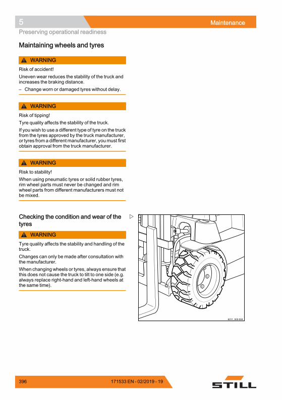
5 MaintenancePreserving operational readiness
Maintaining wheels and tyres
WARNINGRisk of accident!Uneven wear reduces the stability of the truck andincreases the braking distance.– Change worn or damaged tyres without delay.
WARNINGRisk of tipping!Tyre quality affects the stability of the truck.If you wish to use a different type of tyre on the truckfrom the tyres approved by the truck manufacturer,or tyres froma differentmanufacturer, youmust firstobtain approval from the truck manufacturer.
WARNINGRisk to stability!When using pneumatic tyres or solid rubber tyres,rim wheel parts must never be changed and rimwheel parts from different manufacturers must notbe mixed.
6311_003-004
Checking the condition and wear of thetyres
WARNINGTyre quality affects the stability and handling of thetruck.Changes can only be made after consultation withthe manufacturer.When changingwheels or tyres, always ensure thatthis does not cause the truck to tilt to one side (e.g.always replace right-hand and left-hand wheels atthe same time).
396 171533 EN - 02/2019 - 19
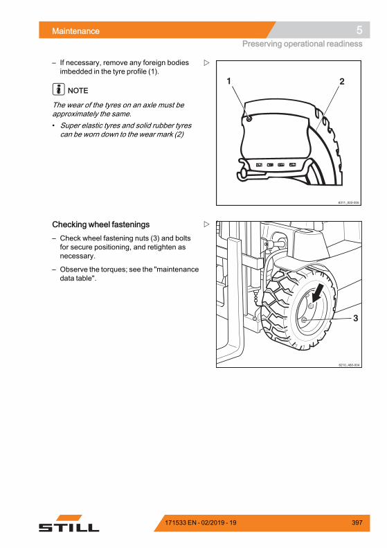
Maintenance 5Preserving operational readiness
21
6311_003-005
– If necessary, remove any foreign bodiesimbedded in the tyre profile (1).
NOTE
The wear of the tyres on an axle must beapproximately the same.• Super elastic tyres and solid rubber tyrescan be worn down to the wear mark (2)
6210_460-004
3
Checking wheel fastenings– Check wheel fastening nuts (3) and boltsfor secure positioning, and retighten asnecessary.
– Observe the torques; see the "maintenancedata table".
171533 EN - 02/2019 - 19 397
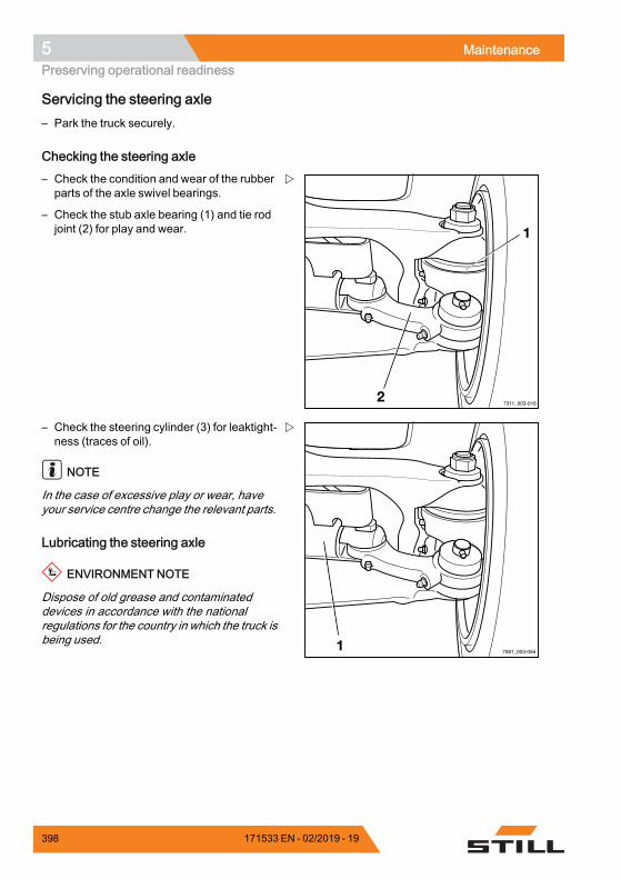
5 MaintenancePreserving operational readiness
Servicing the steering axle– Park the truck securely.
Checking the steering axle– Check the condition and wear of the rubberparts of the axle swivel bearings.
– Check the stub axle bearing (1) and tie rodjoint (2) for play and wear.
– Check the steering cylinder (3) for leaktight-ness (traces of oil).
NOTE
In the case of excessive play or wear, haveyour service centre change the relevant parts.
Lubricating the steering axle
ENVIRONMENT NOTE
Dispose of old grease and contaminateddevices in accordance with the nationalregulations for the country in which the truck isbeing used.
398 171533 EN - 02/2019 - 19
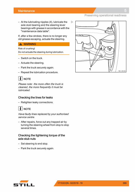
Maintenance 5Preserving operational readiness
– At the lubricating nipples (4), lubricate theaxle stub bearing and the steering leverbearingswith grease in accordancewith the"maintenance data table".
If, after a few strokes, there is no longer anyold grease escaping, actuate the steering.
WARNINGRisk of crushing!Do not actuate the steering during lubrication.
– Switch on the truck.
– Actuate the steering.
– Park the truck securely again.
– Repeat the lubrication procedure.
NOTE
Please note: the more often the truck iscleaned, the more frequently it must belubricated.
Checking the lines for leaks– Retighten leaky connections.
NOTE
Have faulty lines replaced by your authorisedservice centre.
– After repairs, force out any trapped air byturning the steering wheel from stop to stopseveral times.
Checking the tightening torque of theaxle stub nuts– Set steering to end stop.
– Park the truck securely again.
171533 EN - 02/2019 - 19 399
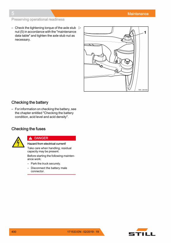
5 MaintenancePreserving operational readiness
– Check the tightening torque of the axle stubnut (5) in accordancewith the "maintenancedata table" and tighten the axle stub nut asnecessary.
Checking the battery– For information on checking the battery, seethe chapter entitled "Checking the batterycondition, acid level and acid density".
Checking the fuses
DANGERHazard from electrical current!Take care when handling; residualcapacity may be present.Before starting the following mainten-ance work:– Park the truck securely.– Disconnect the battery male
connector.
400 171533 EN - 02/2019 - 19
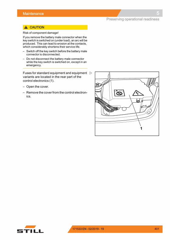
Maintenance 5Preserving operational readiness
CAUTIONRisk of component damage!If you remove the battery male connector when thekey switch is switched on (under load), an arcwill beproduced. This can lead to erosion at the contacts,which considerably shortens their service life.– Switch off the key switch before the battery male
connector is disconnected.– Do not disconnect the battery male connector
while the key switch is switched on, except in anemergency.
1
Fuses for standard equipment and equipmentvariants are located in the rear part of thecontrol electronics (1).
– Open the cover.
– Remove the cover from the control electron-ics.
171533 EN - 02/2019 - 19 401
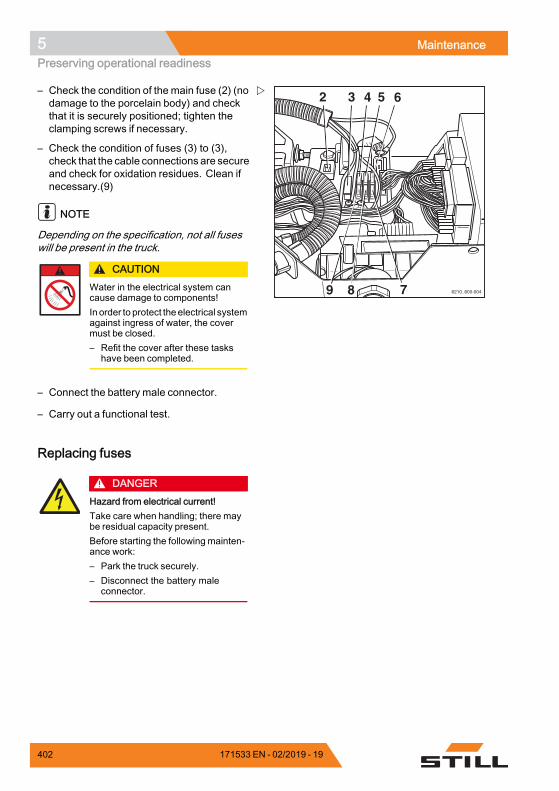
5 MaintenancePreserving operational readiness
2 3 4 5
79 8
6
6210_600-004
– Check the condition of the main fuse (2) (nodamage to the porcelain body) and checkthat it is securely positioned; tighten theclamping screws if necessary.
– Check the condition of fuses (3) to (3),check that the cable connections are secureand check for oxidation residues. Clean ifnecessary.(9)
NOTE
Depending on the specification, not all fuseswill be present in the truck.
CAUTIONWater in the electrical system cancause damage to components!In order to protect theelectrical systemagainst ingress of water, the covermust be closed.– Refit the cover after these tasks
have been completed.
– Connect the battery male connector.
– Carry out a functional test.
Replacing fuses
DANGERHazard from electrical current!Take care when handling; there maybe residual capacity present.Before starting the following mainten-ance work:– Park the truck securely.– Disconnect the battery male
connector.
402 171533 EN - 02/2019 - 19
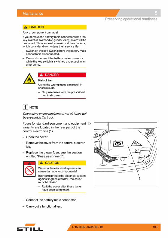
Maintenance 5Preserving operational readiness
CAUTIONRisk of component damage!If you remove the battery male connector when thekey switch is switched on (under load), an arcwill beproduced. This can lead to erosion at the contacts,which considerably shortens their service life.– Switch off the key switch before the battery male
connector is disconnected.– Do not disconnect the battery male connector
while the key switch is switched on, except in anemergency.
DANGERRisk of fire!Using the wrong fuses can result inshort circuits.– Only use fuses with the prescribed
nominal current.
NOTE
Depending on the equipment, not all fuses willbe present in the truck.
1
Fuses for standard equipment and equipmentvariants are located in the rear part of thecontrol electronics (1).
– Open the cover.
– Remove the cover from the control electron-ics.
– Replace the blown fuse; see the sectionentitled "Fuse assignment".
CAUTIONWater in the electrical system cancause damage to components!In order to protect theelectrical systemagainst ingress of water, the covermust be closed.– Refit the cover after these tasks
have been completed.
– Connect the battery male connector.
– Carry out a functional test.
171533 EN - 02/2019 - 19 403
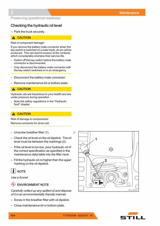
5 MaintenancePreserving operational readiness
Checking the hydraulic oil level– Park the truck securely.
CAUTIONRisk of component damage!If you remove the battery male connector when thekey switch is switched on (under load), an arcwill beproduced. This can lead to erosion at the contacts,which considerably shortens their service life.– Switch off the key switch before the battery male
connector is disconnected.– Only disconnect the battery male connector with
the key switch switched on in an emergency.
– Disconnect the battery male connector.
– Remove maintenance lid or bottom plate.
CAUTIONHydraulic oils are hazardous to your health and areunder pressure during operation.– Note the safety regulations in the "Hydraulic
fluid" chapter.
CAUTIONRisk of damage to components!Remove connector for drive unit.
1
2
6210_700-002
– Unscrew breather filter (1).
– Check the oil level on the oil dipstick. The oillevel must be between the markings (2).
– If the oil level is too low, pour hydraulic oil ofthe correct specification as specified in themaintenance data table into the filler neck.
– Fill the hydraulic oil no higher than the uppermarking on the oil dipstick.
NOTE
Use a funnel.
ENVIRONMENT NOTE
Carefully collect up any spilled oil and disposeof it in an environmentally friendly manner.
– Screw in the breather filter with oil dipstick.
– Close maintenance lid or bottom plate.
404 171533 EN - 02/2019 - 19
Maintenance 5Preserving operational readiness
– Connect the battery male connector.
Checking the hydraulic system forleak tightness
WARNINGHydraulic oil is hazardous to health!Hydraulic oil under pressure canescape from leaking pipes and lines,and cause injuries.– Wear suitable protective gloves,
protection goggles etc.
CAUTIONHydraulic hoses become brittle!– Do not store hydraulic hoses for more than two
years.– Do not use hydraulic hoses for more than six
years if they are subject to normal wear.– Do not use hydraulic hoses for more than two
years if they are subject to a high level of wear.– Complywith the specifications ofDGUV113-020
in Germany.– Outside of Germany, observe the national
regulations for the country of use.
– Check pipe and hose connection screwjoints for leaks (traces of oil).
Replace hose lines if they display the followingabnormalities:• Outer layer has been damaged, or is brittleor cracked
• Leaking• Deformation (e.g. with blisters or kinks)• A fitting has come loose• A fitting is badly damaged or corroded
Replace pipes if they display the followingabnormalities:• Abrasion• Deformation and bending• Leaking
171533 EN - 02/2019 - 19 405
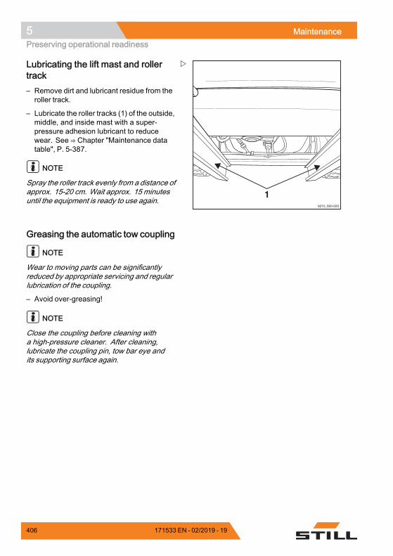
5 MaintenancePreserving operational readiness
16210_800-020
Lubricating the lift mast and rollertrack– Remove dirt and lubricant residue from theroller track.
– Lubricate the roller tracks (1) of the outside,middle, and inside mast with a super-pressure adhesion lubricant to reducewear. See ⇒ Chapter "Maintenance datatable", P. 5-387.
NOTE
Spray the roller track evenly from a distance ofapprox. 15-20 cm. Wait approx. 15 minutesuntil the equipment is ready to use again.
Greasing the automatic tow coupling
NOTE
Wear to moving parts can be significantlyreduced by appropriate servicing and regularlubrication of the coupling.
– Avoid over-greasing!
NOTE
Close the coupling before cleaning witha high-pressure cleaner. After cleaning,lubricate the coupling pin, tow bar eye andits supporting surface again.
406 171533 EN - 02/2019 - 19

Maintenance 5Preserving operational readiness
3
7321_003-091
21
Model RO*243– Pull out the safety handle (3).
– Push the hand lever (2) upwards.
– Grease using the lubricating nipple(1) inaccordance with the maintenance datatable; see ⇒ Chapter "Maintenance datatable", P. 5-387.
– Close the coupling by raising the couplingpin with a suitable tool.
– For journeys with a rigid drawbar trailer,lubricate the underside of the tow bar eyeand the supporting surface on the coupling.
7321_003-092
– Determine the wear on the coupling pin.
The diameter of the spherical part must not beless than 36.5 mm.
Model RO*244 A– Open coupling.
Wartung_Rockinger 244 A
1– Grease using the lubricating nipple(1) inaccordance with the maintenance datatable; see ⇒ Chapter "Maintenance datatable", P. 5-387.
– Grease coupling pin, tow bar eye and itssupporting surface.
171533 EN - 02/2019 - 19 407
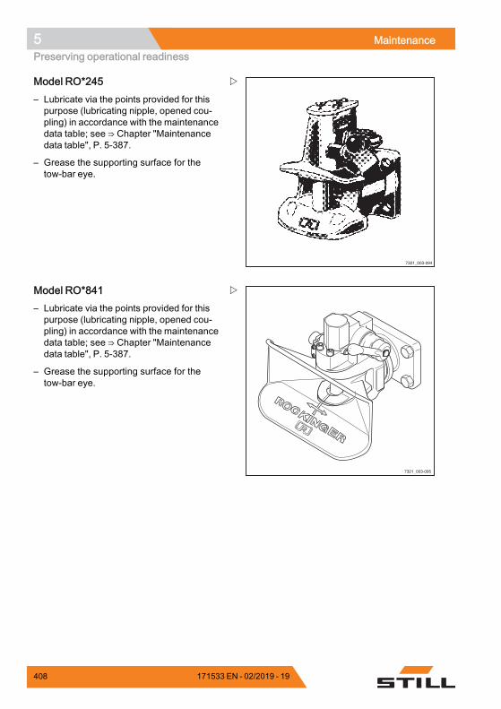
5 MaintenancePreserving operational readiness
7321_003-094
Model RO*245– Lubricate via the points provided for thispurpose (lubricating nipple, opened cou-pling) in accordance with the maintenancedata table; see ⇒ Chapter "Maintenancedata table", P. 5-387.
– Grease the supporting surface for thetow-bar eye.
7321_003-095
Model RO*841– Lubricate via the points provided for thispurpose (lubricating nipple, opened cou-pling) in accordance with the maintenancedata table; see ⇒ Chapter "Maintenancedata table", P. 5-387.
– Grease the supporting surface for thetow-bar eye.
408 171533 EN - 02/2019 - 19
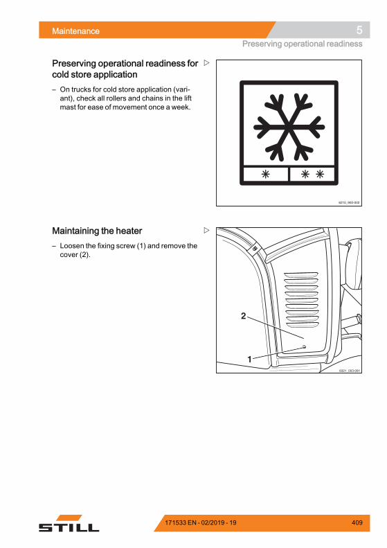
Maintenance 5Preserving operational readiness
6210_900-002
Preserving operational readiness forcold store application– On trucks for cold store application (vari-ant), check all rollers and chains in the liftmast for ease of movement once a week.
6321_003-091
1
2
Maintaining the heater– Loosen the fixing screw (1) and remove thecover (2).
171533 EN - 02/2019 - 19 409
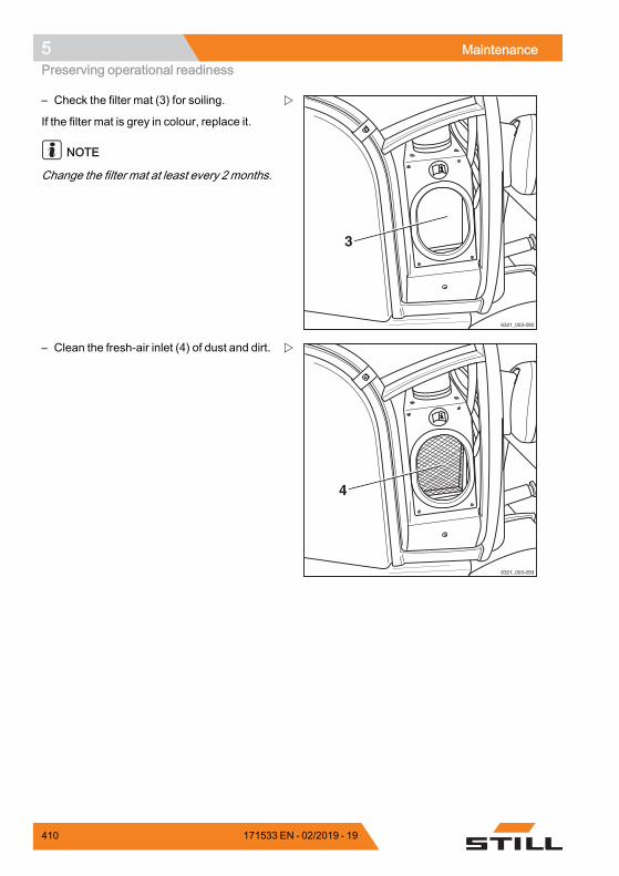
5 MaintenancePreserving operational readiness
6321_003-092
3
– Check the filter mat (3) for soiling.
If the filter mat is grey in colour, replace it.
NOTE
Change the filter mat at least every 2 months.
6321_003-093
4
– Clean the fresh-air inlet (4) of dust and dirt.
410 171533 EN - 02/2019 - 19
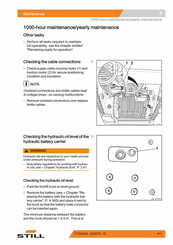
Maintenance 51000-hour maintenance/yearly maintenance
1000-hour maintenance/yearly maintenanceOther tasks– Perform all tasks required to maintainfull operability; see the chapter entitled"Remaining ready for operation".
6327_110-001
1 2Checking the cable connections– Check supply cable of pumpmotor (1) andtraction motor (2) for secure positioning,condition and insulation .
NOTE
Oxidised connections and brittle cables leadto voltage drops , so causing malfunctions.
– Remove oxidised connections and replacebrittle cables.
6327_003-045
1
Checking the hydraulic oil level of thehydraulic battery carrier
WARNINGHydraulic oils are hazardous to your health and areunder pressure during operation.– Note safety regulations for working with hydrau-
lic oils; see ⇒ Chapter "Hydraulic fluid", P. 2-51.
Checking the hydraulic oil level– Park the forklift truck on level ground.
– Remove the battery (see ⇒ Chapter "Re-placing the battery with the hydraulic bat-tery carrier", P. 4-345) and place it next tothe truck so that the battery male connectorcan be inserted again.
The minimum distance between the batteryand the truck should be > 0.5 m. This is to
171533 EN - 02/2019 - 19 411
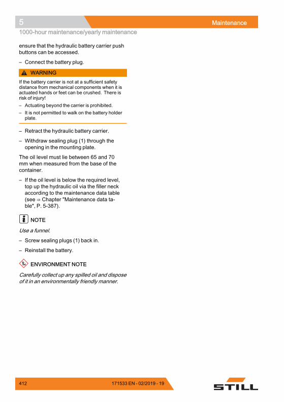
5 Maintenance1000-hour maintenance/yearly maintenance
ensure that the hydraulic battery carrier pushbuttons can be accessed.
– Connect the battery plug.
WARNINGIf the battery carrier is not at a sufficient safetydistance from mechanical components when it isactuated hands or feet can be crushed. There isrisk of injury!– Actuating beyond the carrier is prohibited.– It is not permitted to walk on the battery holder
plate.
– Retract the hydraulic battery carrier.
– Withdraw sealing plug (1) through theopening in the mounting plate.
The oil level must lie between 65 and 70mm when measured from the base of thecontainer.
– If the oil level is below the required level,top up the hydraulic oil via the filler neckaccording to the maintenance data table(see ⇒ Chapter "Maintenance data ta-ble", P. 5-387).
NOTE
Use a funnel.
– Screw sealing plugs (1) back in.
– Reinstall the battery.
ENVIRONMENT NOTE
Carefully collect up any spilled oil and disposeof it in an environmentally friendly manner.
412 171533 EN - 02/2019 - 19
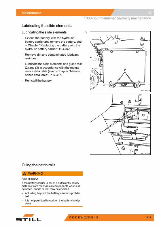
Maintenance 51000-hour maintenance/yearly maintenance
Lubricating the slide elements
2
6321_003-124
6321_003-125
3
Lubricating the slide elements– Extend the battery with the hydraulicbattery carrier and remove the battery, see⇒ Chapter "Replacing the battery with thehydraulic battery carrier", P. 4-345.
– Remove dirt and contaminated lubricantresidues.
– Lubricate the slide elements and guide rails(2) and (3) in accordance with the mainte-nance data table (see ⇒ Chapter "Mainte-nance data table", P. 5-387.
– Reinstall the battery.
Oiling the catch rails
WARNINGRisk of injury!If the battery carrier is not at a sufficiently safetydistance from mechanical components when it isactuated, hands or feet may be crushed.– Actuating beyond the battery carrier is prohibi-
ted.– It is not permitted to walk on the battery holder
plate.
171533 EN - 02/2019 - 19 413
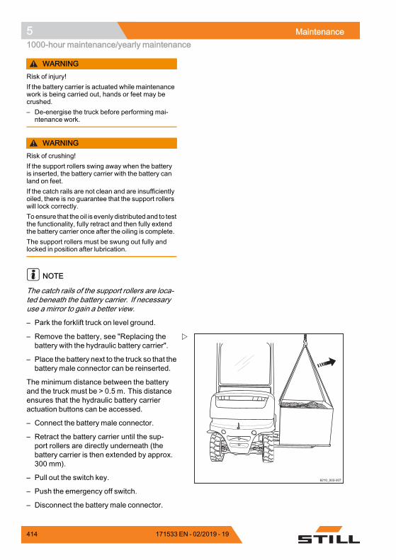
5 Maintenance1000-hour maintenance/yearly maintenance
WARNINGRisk of injury!If the battery carrier is actuated while maintenancework is being carried out, hands or feet may becrushed.– De-energise the truck before performing mai-
ntenance work.
WARNINGRisk of crushing!If the support rollers swing away when the batteryis inserted, the battery carrier with the battery canland on feet.If the catch rails are not clean and are insufficientlyoiled, there is no guarantee that the support rollerswill lock correctly.Toensure that theoil is evenly distributedand to testthe functionality, fully retract and then fully extendthe battery carrier once after the oiling is complete.The support rollers must be swung out fully andlocked in position after lubrication.
NOTE
The catch rails of the support rollers are loca-ted beneath the battery carrier. If necessaryuse a mirror to gain a better view.
– Park the forklift truck on level ground.
6210_003-007
– Remove the battery, see "Replacing thebattery with the hydraulic battery carrier".
– Place the battery next to the truck so that thebattery male connector can be reinserted.
The minimum distance between the batteryand the truck must be > 0.5 m. This distanceensures that the hydraulic battery carrieractuation buttons can be accessed.
– Connect the battery male connector.
– Retract the battery carrier until the sup-port rollers are directly underneath (thebattery carrier is then extended by approx.300 mm).
– Pull out the switch key.
– Push the emergency off switch.
– Disconnect the battery male connector.
414 171533 EN - 02/2019 - 19
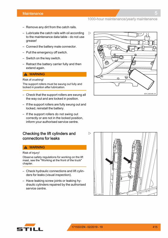
Maintenance 51000-hour maintenance/yearly maintenance
– Remove any dirt from the catch rails.
6210_003-049_V2
– Lubricate the catch rails with oil accordingto the maintenance data table - do not usegrease!
– Connect the battery male connector.
– Pull the emergency off switch.
– Switch on the key switch.
– Retract the battery carrier fully and thenextend again.
WARNINGRisk of crushing!The support rollers must be swung out fully andlocked in position after lubrication.
– Check that the support rollers are swung allthe way out and are locked in position.
– If the support rollers are fully swung out andlocked, reinstall the battery.
– If the support rollers do not swing outcorrectly or are not in the locked position,inform your authorised service centre.
6327_003-016
Checking the lift cylinders andconnections for leaks
WARNINGRisk of injury!Observe safety regulations for working on the liftmast, see the "Working at the front of the truck"chapter.
– Check hydraulic connections and lift cylin-ders for leaks (visual inspection).
– Have leaking screw joints or leaking hy-draulic cylinders repaired by the authorisedservice centre.
171533 EN - 02/2019 - 19 415
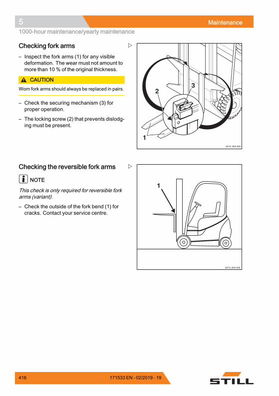
5 Maintenance1000-hour maintenance/yearly maintenance
6210_842-002
1
23
Checking fork arms– Inspect the fork arms (1) for any visibledeformation. The wear must not amount tomore than 10% of the original thickness.
CAUTIONWorn fork arms should always be replaced in pairs.
– Check the securing mechanism (3) forproper operation.
– The locking screw (2) that prevents dislodg-ing must be present.
Checking the reversible fork arms
NOTE
This check is only required for reversible forkarms (variant).
– Check the outside of the fork bend (1) forcracks. Contact your service centre.
416 171533 EN - 02/2019 - 19
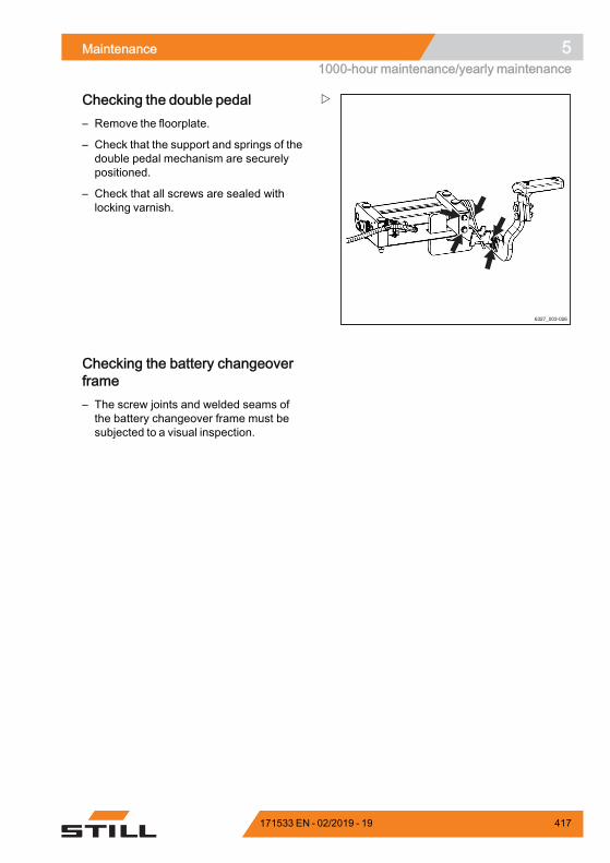
Maintenance 51000-hour maintenance/yearly maintenance
6327_003-026
Checking the double pedal– Remove the floorplate.
– Check that the support and springs of thedouble pedal mechanism are securelypositioned.
– Check that all screws are sealed withlocking varnish.
Checking the battery changeoverframe– The screw joints and welded seams ofthe battery changeover frame must besubjected to a visual inspection.
171533 EN - 02/2019 - 19 417

5 Maintenance1000-hour maintenance/yearly maintenance
418 171533 EN - 02/2019 - 19

6
Technical data
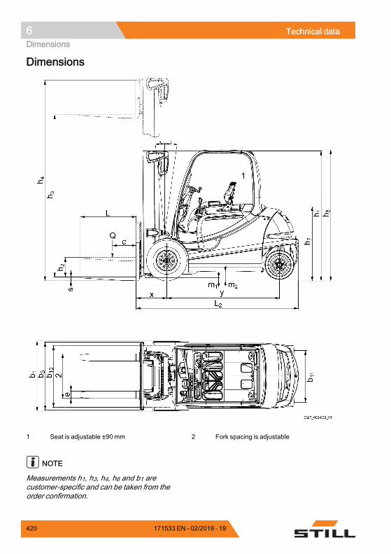
6 Technical dataDimensions
Dimensions
1 Seat is adjustable ±90 mm 2 Fork spacing is adjustable
NOTE
Measurements h1, h3, h4, h6 and b1 arecustomer-specific and can be taken from theorder confirmation.
420 171533 EN - 02/2019 - 19
Technical data 6Dimensions
Centre of gravity "S" (distance measuredfrom the front axle)
RX60-35/600 (6367) 945 mm
RX60-40 (6327) 945 mm
RX60-40/600 (6368) 945 mm
RX60-45 (6328) 985.5 mm
RX60-45/600 (6369) 985.5 mm
RX60-50 (6329) 1023 mm
RX60-50/600 (6330) 1023 mm
NOTE
The specified centre of gravity "S" relatesto trucks with standard equipment. If, forexample, the truck is equipped with a differentlift mast, attachment or driver protectionstructure, this value is only a guide value. Ifnecessary, the centre of gravity "S" must bedetermined on an individual basis for eachtruck.
171533 EN - 02/2019 - 19 421
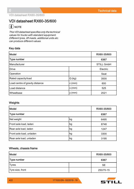
6 Technical dataVDI datasheet RX60-35/600
VDI datasheet RX60-35/600NOTE
ThisVDI datasheet specifies only the technicalvalues for trucks with standard equipment.Different tyres, lift masts, additional units etc.can produce different values.
Key data
Model RX60-35/600
Type number 6367
Manufacturer STILL GmbH
Drive Electric
Operation Seat
Rated capacity/load Q (kg) 3500
Load centre of gravity distance c (mm) 600
Load distance x (mm) 525
Wheelbase y (mm) 2021.
Weights
Model RX60-35/600
Type number 6367
Net weight kg 6495
Front axle load, laden kg 8748
Rear axle load, laden kg 1247
Front axle load, unladen kg 3300
Rear axle load, unladen kg 3195.
Wheels, chassis frame
Model RX60-35/600
Type number 6367
Tyres SE
Tyre size, front 250/70-15
422 171533 EN - 02/2019 - 19
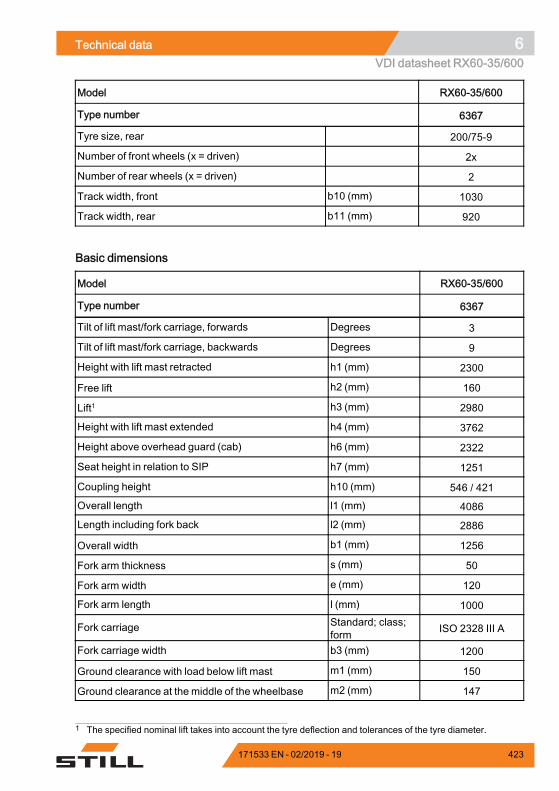
Technical data 6VDI datasheet RX60-35/600
Model RX60-35/600
Type number 6367
Tyre size, rear 200/75-9
Number of front wheels (x = driven) 2x
Number of rear wheels (x = driven) 2
Track width, front b10 (mm) 1030
Track width, rear b11 (mm) 920.
Basic dimensions
Model RX60-35/600
Type number 6367
Tilt of lift mast/fork carriage, forwards Degrees 3
Tilt of lift mast/fork carriage, backwards Degrees 9
Height with lift mast retracted h1 (mm) 2300
Free lift h2 (mm) 160
Lift1 h3 (mm) 2980
Height with lift mast extended h4 (mm) 3762
Height above overhead guard (cab) h6 (mm) 2322
Seat height in relation to SIP h7 (mm) 1251
Coupling height h10 (mm) 546 / 421
Overall length l1 (mm) 4086
Length including fork back l2 (mm) 2886
Overall width b1 (mm) 1256
Fork arm thickness s (mm) 50
Fork arm width e (mm) 120
Fork arm length l (mm) 1000
Fork carriage Standard; class;form ISO 2328 III A
Fork carriage width b3 (mm) 1200
Ground clearance with load below lift mast m1 (mm) 150
Ground clearance at the middle of the wheelbase m2 (mm) 147
1 The specified nominal lift takes into account the tyre deflection and tolerances of the tyre diameter.
171533 EN - 02/2019 - 19 423
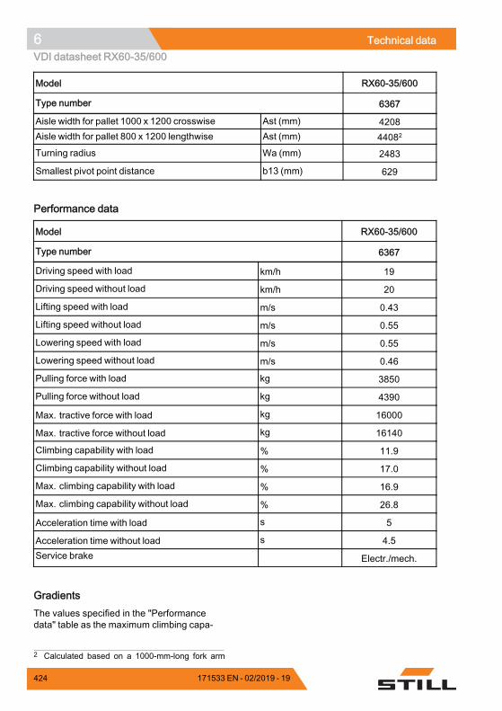
6 Technical dataVDI datasheet RX60-35/600
Model RX60-35/600
Type number 6367
Aisle width for pallet 1000 x 1200 crosswise Ast (mm) 4208Aisle width for pallet 800 x 1200 lengthwise Ast (mm) 44082
Turning radius Wa (mm) 2483
Smallest pivot point distance b13 (mm) 629.
Performance data
Model RX60-35/600
Type number 6367
Driving speed with load km/h 19
Driving speed without load km/h 20
Lifting speed with load m/s 0.43
Lifting speed without load m/s 0.55
Lowering speed with load m/s 0.55
Lowering speed without load m/s 0.46
Pulling force with load kg 3850
Pulling force without load kg 4390
Max. tractive force with load kg 16000
Max. tractive force without load kg 16140
Climbing capability with load % 11.9
Climbing capability without load % 17.0
Max. climbing capability with load % 16.9
Max. climbing capability without load % 26.8
Acceleration time with load s 5
Acceleration time without load s 4.5Service brake Electr./mech.
.
GradientsThe values specified in the "Performancedata" table as the maximum climbing capa-
2 Calculated based on a 1000-mm-long fork arm
424 171533 EN - 02/2019 - 19
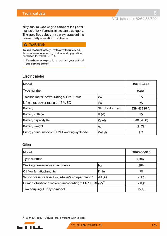
Technical data 6VDI datasheet RX60-35/600
bility can be used only to compare the perfor-mance of forklift trucks in the same category.The specified values in no way represent thenormal daily operating conditions.
WARNINGTo use the truck safely – with or without a load –the maximum ascending or descending gradientpermitted for travel is 15 %.– If you have any questions, contact your authori-
sed service centre.
Electric motor
Model RX60-35/600
Type number 6367
Traction motor, power rating at S2: 60 min kW 15
Lift motor, power rating at 15 % ED kW 25
Battery Standard; circuit DIN 43536 A
Battery voltage U (V) 80
Battery capacity K5 K5 Ah 840 (-930)
Battery weight kg 2178
Energy consumption: 60 VDI working cycles/hour kWh/h 9.7.
Other
Model RX60-35/600
Type number 6367
Working pressure for attachments bar 250
Oil flow for attachments l/min 30
Sound pressure level LpAZ (driver's compartment)3 dB (A) < 70
Human vibration: acceleration according to EN 13059 m/s2 < 0.7
Tow coupling, DIN type/model Bolt.
3 Without cab. Values are different with a cab.
171533 EN - 02/2019 - 19 425
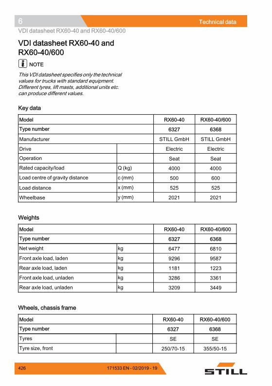
6 Technical dataVDI datasheet RX60-40 and RX60-40/600
VDI datasheet RX60-40 andRX60-40/600
NOTE
ThisVDI datasheet specifies only the technicalvalues for trucks with standard equipment.Different tyres, lift masts, additional units etc.can produce different values.
Key data
Model RX60-40 RX60-40/600
Type number 6327 6368
Manufacturer STILL GmbH STILL GmbH
Drive Electric Electric
Operation Seat Seat
Rated capacity/load Q (kg) 4000 4000
Load centre of gravity distance c (mm) 500 600
Load distance x (mm) 525 525
Wheelbase y (mm) 2021 2021.
Weights
Model RX60-40 RX60-40/600
Type number 6327 6368
Net weight kg 6477 6810
Front axle load, laden kg 9296 9587
Rear axle load, laden kg 1181 1223
Front axle load, unladen kg 3286 3361
Rear axle load, unladen kg 3209 3449.
Wheels, chassis frame
Model RX60-40 RX60-40/600
Type number 6327 6368
Tyres SE SE
Tyre size, front 250/70-15 355/50-15
426 171533 EN - 02/2019 - 19
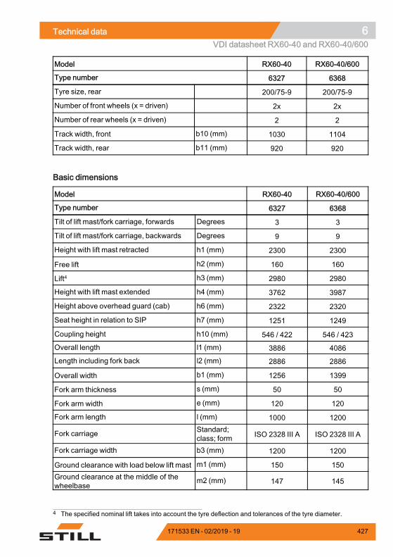
Technical data 6VDI datasheet RX60-40 and RX60-40/600
Model RX60-40 RX60-40/600
Type number 6327 6368
Tyre size, rear 200/75-9 200/75-9
Number of front wheels (x = driven) 2x 2x
Number of rear wheels (x = driven) 2 2
Track width, front b10 (mm) 1030 1104
Track width, rear b11 (mm) 920 920.
Basic dimensions
Model RX60-40 RX60-40/600
Type number 6327 6368
Tilt of lift mast/fork carriage, forwards Degrees 3 3
Tilt of lift mast/fork carriage, backwards Degrees 9 9
Height with lift mast retracted h1 (mm) 2300 2300
Free lift h2 (mm) 160 160
Lift4 h3 (mm) 2980 2980
Height with lift mast extended h4 (mm) 3762 3987
Height above overhead guard (cab) h6 (mm) 2322 2320
Seat height in relation to SIP h7 (mm) 1251 1249
Coupling height h10 (mm) 546 / 422 546 / 423
Overall length l1 (mm) 3886 4086
Length including fork back l2 (mm) 2886 2886
Overall width b1 (mm) 1256 1399
Fork arm thickness s (mm) 50 50
Fork arm width e (mm) 120 120
Fork arm length l (mm) 1000 1200
Fork carriage Standard;class; form ISO 2328 III A ISO 2328 III A
Fork carriage width b3 (mm) 1200 1200
Ground clearance with load below lift mast m1 (mm) 150 150Ground clearance at the middle of thewheelbase
m2 (mm) 147 145
4 The specified nominal lift takes into account the tyre deflection and tolerances of the tyre diameter.
171533 EN - 02/2019 - 19 427

6 Technical dataVDI datasheet RX60-40 and RX60-40/600
Model RX60-40 RX60-40/600
Type number 6327 6368
Aisle width for pallet 1000 x 1200 crosswise Ast (mm) 4208 4208
Aisle width for pallet 800 x 1200 lengthwise Ast (mm) 4408 44085
Turning radius Wa (mm) 2483 2483
Smallest pivot point distance b13 (mm) 629 629.
Performance data
Model RX60-40 RX60-40/600
Type number 6327 6368
Driving speed with load km/h 19 19
Driving speed without load km/h 20 20
Lifting speed with load m/s 0.40 0.38
Lifting speed without load m/s 0.55 0.46
Lowering speed with load m/s 0.55 0.55
Lowering speed without load m/s 0.47 0.48
Pulling force with load kg 3770 3700
Pulling force without load kg 4390 4470
Max. tractive force with load kg 15940 15900
Max. tractive force without load kg 16140 16150
Climbing capability with load % 11.3 10.6
Climbing capability without load % 17.0 16.8
Max. climbing capability with load % 15.5 15.5
Max. climbing capability without load % 25.9 25.5
Acceleration time with load s 5.1 5.1
Acceleration time without load s 4.5 4.5
Service brake Electr./mech. Electr./mech..
GradientsThe values specified in the "Performancedata" table as the maximum climbing capa-
5 Calculated based on a 1000-mm-long fork arm
428 171533 EN - 02/2019 - 19
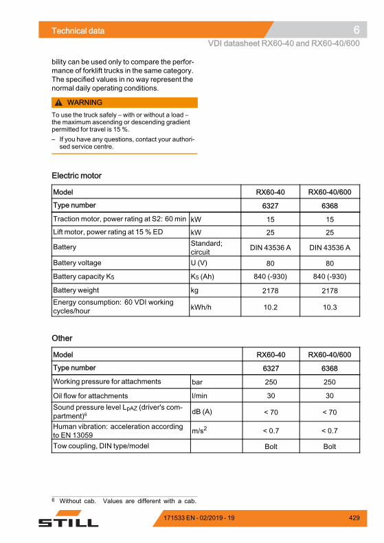
Technical data 6VDI datasheet RX60-40 and RX60-40/600
bility can be used only to compare the perfor-mance of forklift trucks in the same category.The specified values in no way represent thenormal daily operating conditions.
WARNINGTo use the truck safely – with or without a load –the maximum ascending or descending gradientpermitted for travel is 15 %.– If you have any questions, contact your authori-
sed service centre.
Electric motor
Model RX60-40 RX60-40/600
Type number 6327 6368
Traction motor, power rating at S2: 60 min kW 15 15
Lift motor, power rating at 15 % ED kW 25 25
Battery Standard;circuit DIN 43536 A DIN 43536 A
Battery voltage U (V) 80 80
Battery capacity K5 K5 (Ah) 840 (-930) 840 (-930)
Battery weight kg 2178 2178Energy consumption: 60 VDI workingcycles/hour kWh/h 10.2 10.3
.
Other
Model RX60-40 RX60-40/600
Type number 6327 6368
Working pressure for attachments bar 250 250
Oil flow for attachments l/min 30 30Sound pressure level LpAZ (driver's com-partment)6 dB (A) < 70 < 70
Human vibration: acceleration accordingto EN 13059 m/s2 < 0.7 < 0.7
Tow coupling, DIN type/model Bolt Bolt.
6 Without cab. Values are different with a cab.
171533 EN - 02/2019 - 19 429

6 Technical dataVDI datasheet RX60-45 and RX60-45/600
VDI datasheet RX60-45 andRX60-45/600
NOTE
ThisVDI datasheet specifies only the technicalvalues for trucks with standard equipment.Different tyres, lift masts, additional units etc.can produce different values.
Key data
Model RX60-45 RX60-45/600
Type number 6328 6369
Manufacturer STILL GmbH STILL GmbH
Drive Electric Electric
Operation Seat Seat
Rated capacity/load Q (kg) 4500 4500
Load centre of gravity distance c (mm) 500 600
Load distance x (mm) 525 535
Wheelbase y (mm) 2021 2021.
Weights
Model RX60-45 RX60-45/600
Type number 6328 6369
Net weight kg 6793 7145
Front axle load, laden kg 10112 10441
Rear axle load, laden kg 1184 1204
Front axle load, unladen kg 3329 3413
Rear axle load, unladen kg 3463 3732.
Wheels, chassis frame
Model RX60-45 RX60-45/600
Type number 6328 6369
Tyres SE SE
Tyre size, front 355/50-15 355/50-15
430 171533 EN - 02/2019 - 19

Technical data 6VDI datasheet RX60-45 and RX60-45/600
Model RX60-45 RX60-45/600
Type number 6328 6369
Tyre size, rear 200/75-9 200/75-9
Number of front wheels (x = driven) 2x 2x
Number of rear wheels (x = driven) 2 2
Track width, front b10 (mm) 1104 1104
Track width, rear b11 (mm) 920 920.
Basic dimensions
Model RX60-45 RX60-45/600
Type number 6328 6369
Tilt of lift mast/fork carriage, forwards Degrees 3 3
Tilt of lift mast/fork carriage, backwards Degrees 9 9
Height with lift mast retracted h1 (mm) 2300 2300
Free lift h2 (mm) 160 160
Lift7 h3 (mm) 2980 2980
Height with lift mast extended h4 (mm) 3987 3987
Height above overhead guard (cab) h6 (mm) 2320 2320
Seat height in relation to SIP h7 (mm) 1249 1249
Coupling height h10 (mm) 546 / 424 546 / 425
Overall length l1 (mm) 3886 4096
Length including fork back l2 (mm) 2886 2896
Overall width b1 (mm) 1399 1399
Fork arm thickness s (mm) 50 60
Fork arm width e (mm) 120 130
Fork arm length l (mm) 1200 1200
Fork carriage Standard;class; form ISO 2328 III A ISO 2328 III A
Fork carriage width b3 (mm) 1200 1310
Ground clearance with load below lift mast m1 (mm) 150 150Ground clearance at the middle of thewheelbase
m2 (mm) 145 145
7 The specified nominal lift takes into account the tyre deflection and tolerances of the tyre diameter.
171533 EN - 02/2019 - 19 431

6 Technical dataVDI datasheet RX60-45 and RX60-45/600
Model RX60-45 RX60-45/600
Type number 6328 6369
Aisle width for pallet 1000 x 1200 crosswise Ast (mm) 4208 4218
Aisle width for pallet 800 x 1200 lengthwise Ast (mm) 4408 44188
Turning radius Wa (mm) 2483 2483
Smallest pivot point distance b13 (mm) 629 629.
Performance data
Model RX60-45 RX60-45/600
Type number 6328 6369
Driving speed with load km/h 19 19
Driving speed without load km/h 20 20
Lifting speed with load m/s 0.38 0.38
Lifting speed without load m/s 0.47 0.48
Lowering speed with load m/s 0.55 0.55
Lowering speed without load m/s 0.49 0.50
Pulling force with load kg 3620 3610
Pulling force without load kg 4470 4400
Max. tractive force with load kg 15830 15750
Max. tractive force without load kg 16150 16090
Climbing capability with load % 9.5 9.2
Climbing capability without load % 16.8 15.8
Max. climbing capability with load % 14.3 14.3
Max. climbing capability without load % 24.6 24.1
Acceleration time with load s 5.2 5.2
Acceleration time without load s 4.5 4.6
Service brake Electr./mech. Electr./mech..
GradientsThe values specified in the "Performancedata" table as the maximum climbing capa-
8 Calculated based on a 1000-mm-long fork arm
432 171533 EN - 02/2019 - 19
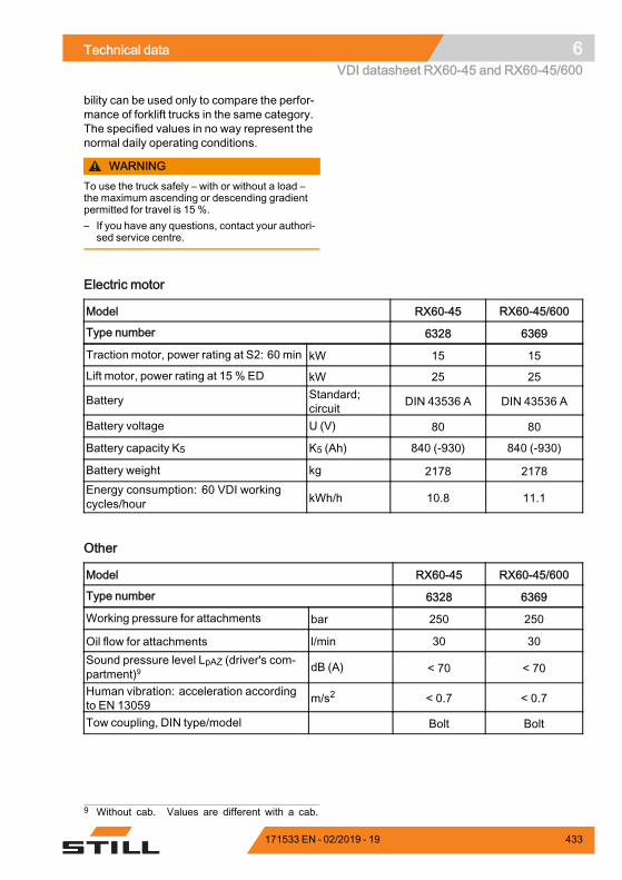
Technical data 6VDI datasheet RX60-45 and RX60-45/600
bility can be used only to compare the perfor-mance of forklift trucks in the same category.The specified values in no way represent thenormal daily operating conditions.
WARNINGTo use the truck safely – with or without a load –the maximum ascending or descending gradientpermitted for travel is 15 %.– If you have any questions, contact your authori-
sed service centre.
Electric motor
Model RX60-45 RX60-45/600
Type number 6328 6369
Traction motor, power rating at S2: 60 min kW 15 15
Lift motor, power rating at 15 % ED kW 25 25
Battery Standard;circuit DIN 43536 A DIN 43536 A
Battery voltage U (V) 80 80
Battery capacity K5 K5 (Ah) 840 (-930) 840 (-930)
Battery weight kg 2178 2178Energy consumption: 60 VDI workingcycles/hour kWh/h 10.8 11.1
.
Other
Model RX60-45 RX60-45/600
Type number 6328 6369
Working pressure for attachments bar 250 250
Oil flow for attachments l/min 30 30Sound pressure level LpAZ (driver's com-partment)9 dB (A) < 70 < 70
Human vibration: acceleration accordingto EN 13059 m/s2 < 0.7 < 0.7
Tow coupling, DIN type/model Bolt Bolt.
9 Without cab. Values are different with a cab.
171533 EN - 02/2019 - 19 433

6 Technical dataVDI datasheet RX60-50 and RX60-50/600
VDI datasheet RX60-50 andRX60-50/600
NOTE
ThisVDI datasheet specifies only the technicalvalues for trucks with standard equipment.Different tyres, lift masts, additional units etc.can produce different values.
Key data
Model RX60-50 RX60-50/600
Type number 6329 6330
Manufacturer STILL GmbH STILL GmbH
Drive Electric Electric
Operation Seat Seat
Rated capacity/load Q (kg) 4990 4990
Load centre of gravity distance c (mm) 500 600
Load distance x (mm) 535 535
Wheelbase y (mm) 2021 2088.
Weights
Model RX60-50 RX60-50/600
Type number 6329 6330
Net weight kg 7121 7711
Front axle load, laden kg 10917 11547
Rear axle load, laden kg 1194 1154
Front axle load, unladen kg 3372 3845
Rear axle load, unladen kg 3749 3866.
Wheels, chassis frame
Model RX60-50 RX60-50/600
Type number 6329 6330
Tyres SE SE
Tyre size, front 355/50-15 355/50-15
434 171533 EN - 02/2019 - 19

Technical data 6VDI datasheet RX60-50 and RX60-50/600
Model RX60-50 RX60-50/600
Type number 6329 6330
Tyre size, rear 200/75-9 200/75-9
Number of front wheels (x = driven) 2x 2x
Number of rear wheels (x = driven) 2 2
Track width, front b10 (mm) 1104 1104
Track width, rear b11 (mm) 920 920.
Basic dimensions
Model RX60-50 RX60-50/600
Type number 6329 6330
Tilt of lift mast/fork carriage, forwards Degrees 3 3
Tilt of lift mast/fork carriage, backwards Degrees 9 6
Height with lift mast retracted h1 (mm) 2300 2300
Free lift h2 (mm) 160 160
Lift10 h3 (mm) 2980 2780
Height with lift mast extended h4 (mm) 3987 3935
Height above overhead guard (cab) h6 (mm) 2320 2320
Seat height in relation to SIP h7 (mm) 1249 1249
Coupling height h10 (mm) 546 / 426 546 / 427
Overall length l1 (mm) 3896 4163
Length including fork back l2 (mm) 2896 2963
Overall width b1 (mm) 1399 1399
Fork arm thickness s (mm) 60 60
Fork arm width e (mm) 130 130
Fork arm length l (mm) 1000 1200
Fork carriage Standard;class; form ISO 2328 III A ISO 2328 III A
Fork carriage width b3 (mm) 1310 1310
Ground clearance with load below lift mast m1 (mm) 150 150Ground clearance at the middle of thewheelbase
m2 (mm) 145 145
10 The specified nominal lift takes into account the tyre deflection and tolerances of the tyre diameter.
171533 EN - 02/2019 - 19 435
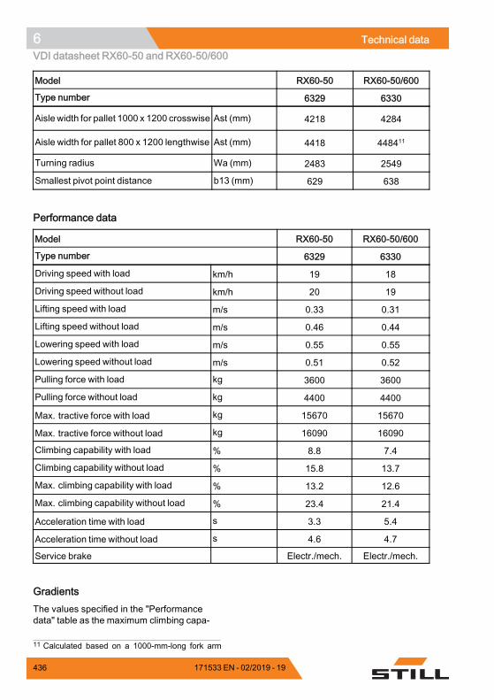
6 Technical dataVDI datasheet RX60-50 and RX60-50/600
Model RX60-50 RX60-50/600
Type number 6329 6330
Aisle width for pallet 1000 x 1200 crosswise Ast (mm) 4218 4284
Aisle width for pallet 800 x 1200 lengthwise Ast (mm) 4418 448411
Turning radius Wa (mm) 2483 2549
Smallest pivot point distance b13 (mm) 629 638.
Performance data
Model RX60-50 RX60-50/600
Type number 6329 6330
Driving speed with load km/h 19 18
Driving speed without load km/h 20 19
Lifting speed with load m/s 0.33 0.31
Lifting speed without load m/s 0.46 0.44
Lowering speed with load m/s 0.55 0.55
Lowering speed without load m/s 0.51 0.52
Pulling force with load kg 3600 3600
Pulling force without load kg 4400 4400
Max. tractive force with load kg 15670 15670
Max. tractive force without load kg 16090 16090
Climbing capability with load % 8.8 7.4
Climbing capability without load % 15.8 13.7
Max. climbing capability with load % 13.2 12.6
Max. climbing capability without load % 23.4 21.4
Acceleration time with load s 3.3 5.4
Acceleration time without load s 4.6 4.7
Service brake Electr./mech. Electr./mech..
GradientsThe values specified in the "Performancedata" table as the maximum climbing capa-
11 Calculated based on a 1000-mm-long fork arm
436 171533 EN - 02/2019 - 19
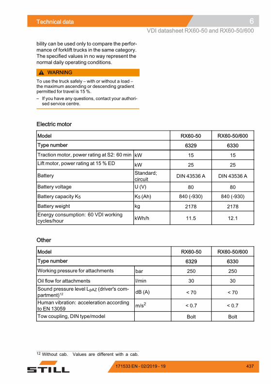
Technical data 6VDI datasheet RX60-50 and RX60-50/600
bility can be used only to compare the perfor-mance of forklift trucks in the same category.The specified values in no way represent thenormal daily operating conditions.
WARNINGTo use the truck safely – with or without a load –the maximum ascending or descending gradientpermitted for travel is 15 %.– If you have any questions, contact your authori-
sed service centre.
Electric motor
Model RX60-50 RX60-50/600
Type number 6329 6330
Traction motor, power rating at S2: 60 min kW 15 15Lift motor, power rating at 15 % ED kW 25 25
Battery Standard;circuit DIN 43536 A DIN 43536 A
Battery voltage U (V) 80 80
Battery capacity K5 K5 (Ah) 840 (-930) 840 (-930)
Battery weight kg 2178 2178Energy consumption: 60 VDI workingcycles/hour kWh/h 11.5 12.1
.
Other
Model RX60-50 RX60-50/600
Type number 6329 6330
Working pressure for attachments bar 250 250
Oil flow for attachments l/min 30 30Sound pressure level LpAZ (driver's com-partment)12 dB (A) < 70 < 70
Human vibration: acceleration accordingto EN 13059 m/s2 < 0.7 < 0.7
Tow coupling, DIN type/model Bolt Bolt.
12 Without cab. Values are different with a cab.
171533 EN - 02/2019 - 19 437
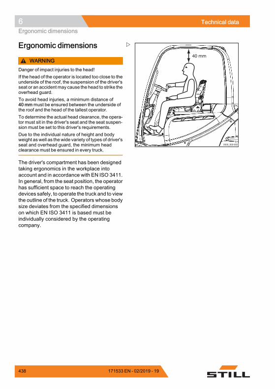
6 Technical dataErgonomic dimensions
0000_003-002
40 mm
Ergonomic dimensions
WARNINGDanger of impact injuries to the head!If the head of the operator is located too close to theunderside of the roof, the suspension of the driver'sseat or an accidentmay cause the head to strike theoverhead guard.To avoid head injuries, a minimum distance of40 mmmust be ensured between the underside ofthe roof and the head of the tallest operator.To determine the actual head clearance, the opera-tor must sit in the driver's seat and the seat suspen-sion must be set to this driver's requirements.Due to the individual nature of height and bodyweight aswell as thewide variety of types of driver'sseat and overhead guard, the minimum headclearance must be ensured in every truck.
The driver's compartment has been designedtaking ergonomics in the workplace intoaccount and in accordance with EN ISO 3411.In general, from the seat position, the operatorhas sufficient space to reach the operatingdevices safely, to operate the truck and to viewthe outline of the truck. Operators whose bodysize deviates from the specified dimensionson which EN ISO 3411 is based must beindividually considered by the operatingcompany.
438 171533 EN - 02/2019 - 19
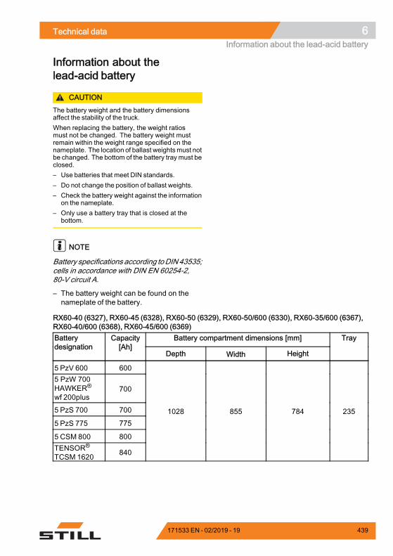
Technical data 6Information about the lead-acid battery
Information about thelead-acid battery
CAUTIONThe battery weight and the battery dimensionsaffect the stability of the truck.When replacing the battery, the weight ratiosmust not be changed. The battery weight mustremain within the weight range specified on thenameplate. The location of ballast weightsmust notbe changed. The bottom of the battery tray must beclosed.– Use batteries that meet DIN standards.– Do not change the position of ballast weights.– Check the battery weight against the information
on the nameplate.– Only use a battery tray that is closed at the
bottom.
NOTE
Battery specifications according toDIN 43535;cells in accordance with DIN EN 60254-2,80-V circuit A.
– The battery weight can be found on thenameplate of the battery.
RX60-40 (6327), RX60-45 (6328), RX60-50 (6329), RX60-50/600 (6330), RX60-35/600 (6367),RX60-40/600 (6368), RX60-45/600 (6369)
Battery compartment dimensions [mm]Batterydesignation
Capacity[Ah]
Depth Width Height
Tray
5 PzV 600 6005 PzW 700HAWKER®
wf 200plus700
5 PzS 700 700
5 PzS 775 775
5 CSM 800 800TENSOR®
TCSM 1620 840
1028 855 784 235
171533 EN - 02/2019 - 19 439
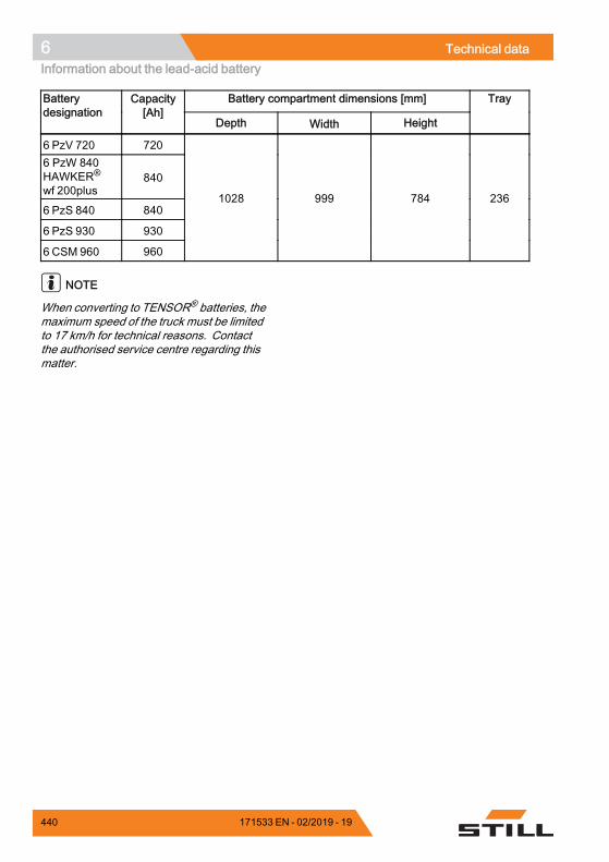
6 Technical dataInformation about the lead-acid battery
Battery compartment dimensions [mm]Batterydesignation
Capacity[Ah]
Depth Width Height
Tray
6 PzV 720 7206 PzW 840HAWKER®
wf 200plus840
6 PzS 840 840
6 PzS 930 930
6 CSM 960 960
1028 999 784 236
NOTE
When converting to TENSOR® batteries, themaximum speed of the truck must be limitedto 17 km/h for technical reasons. Contactthe authorised service centre regarding thismatter.
440 171533 EN - 02/2019 - 19
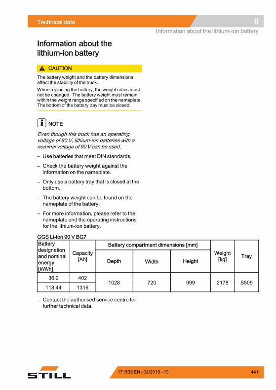
Technical data 6Information about the lithium-ion battery
Information about thelithium-ion battery
CAUTIONThe battery weight and the battery dimensionsaffect the stability of the truck.When replacing the battery, the weight ratios mustnot be changed. The battery weight must remainwithin the weight range specified on the nameplate.The bottom of the battery tray must be closed.
NOTE
Even though this truck has an operatingvoltage of 80 V, lithium-ion batteries with anominal voltage of 90 V can be used.
– Use batteries that meet DIN standards.
– Check the battery weight against theinformation on the nameplate.
– Only use a battery tray that is closed at thebottom.
– The battery weight can be found on thenameplate of the battery.
– For more information, please refer to thenameplate and the operating instructionsfor the lithium-ion battery.
GGS Li-Ion 90 V BG7Battery compartment dimensions [mm]Battery
designationand nominalenergy[kW/h]
Capacity[Ah] Depth Width Height
Weight[kg] Tray
36.2 402
118.44 13161028 720 999 2178 S509
– Contact the authorised service centre forfurther technical data.
171533 EN - 02/2019 - 19 441
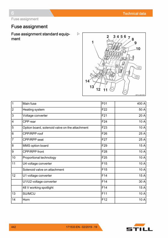
6 Technical dataFuse assignment
Fuse assignment
12 3 4 5 6 7 8
910
111213
14
6210_604-002
Fuse assignment standard equip-ment
1 Main fuse F01 400 A
2 Heating system F22 50 A
3 Voltage converter F21 20 A
4 CPP rear F24 10 A
5 Option board, solenoid valve on the attachment F23 10 A
6 CPP/RPP roof F26 25 A
7 CPP/RPP seat F27 25 A
8 MMS option board F29 15 A
9 CPP/RPP front F28 10 A
10 Proportional technology F25 10 A
11 U4 voltage converter F15 10 A
Solenoid valve on attachment F15 10 A
12 U1 voltage converter F14 15 A
U1/U2 voltage converter F14 30 A
48 V working spotlight F14 15 A
13 SU/MCU F11 10 A
14 Horn F12 10 A.
442 171533 EN - 02/2019 - 19
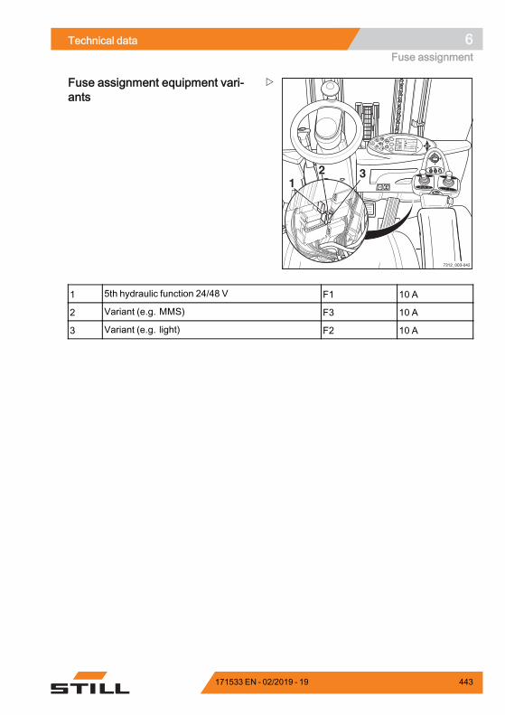
Technical data 6Fuse assignment
8
9
0
6
7
4
2
13
5
F1 F2
7312_003-042
%75
h
2
234,7
12:15
12 3
Fuse assignment equipment vari-ants
1 5th hydraulic function 24/48 V F1 10 A
2 Variant (e.g. MMS) F3 10 A
3 Variant (e.g. light) F2 10 A.
171533 EN - 02/2019 - 19 443

6 Technical dataFuse assignment
444 171533 EN - 02/2019 - 19
Indexg
AAccess authorisation
Changing the password . . . . . . . . . . 106Defining the driver PIN . . . . . . . . . . . 102Entering the access code . . . . . . . . 101Selecting the driver PIN . . . . . . . . . . 104
Access authorisation with PIN code . . . . 99Accessories . . . . . . . . . . . . . . . . . . . . . . . 7Actuate the parking brake
when the truck is moving . . . . . . . . . 148Actuating the drive direction switch
Fingertip version . . . . . . . . . . . . . . . 135Joystick 4Plus version . . . . . . . . . . 135Mini-console version . . . . . . . . . . . . 136Mini-lever version . . . . . . . . . . . . . . 134Multiple-lever version . . . . . . . . . . . 134
Address of manufacturer . . . . . . . . . . . . . IAdjusting the armrest . . . . . . . . . . . . . . . 85Adjusting the fork . . . . . . . . . . . . . . . . . 190Adjusting the steering column . . . . . . . . . 86After cleaning . . . . . . . . . . . . . . . . . . . . 358
AttachmentsAssembly . . . . . . . . . . . . . . . . . . . . 202Controlling using a double
mini-lever . . . . . . . . . . . . . . . . . . 213Controlling using multi-lever
operation . . . . . . . . . . . . . . . . . . 210Controlling using the double
mini-lever and the 5th function . . 215Controlling using the joystick 4Plus . 225Controlling using the quadruple
mini-lever and the 5th function . . 223Controlling using the triple
mini-lever and the 5th function . . 219Controlling with a quadruple
mini-lever . . . . . . . . . . . . . . . . . . 221Controlling with a triple mini-lever . . . 217Controlling with fingertip . . . . . . . . . 229Controlling with fingertip and
5th function . . . . . . . . . . . . . . . . 230General controlling . . . . . . . . . . . . . 208Mounting . . . . . . . . . . . . . . . . . . . . 203Operating with multi-lever controls
and the 5th function . . . . . . . . . . 211Releasing the pressure from the
connections . . . . . . . . . . . . . . . . 204Special risks . . . . . . . . . . . . . . . . . . . 42Taking up a load . . . . . . . . . . . . . . . 236
Automatic lift cut out . . . . . . . . . . . . . . . 178Automatic tow coupling . . . . . . . . . . . . 264
Coupling RO*243 . . . . . . . . . . . . . . 266Coupling RO*244 A . . . . . . . . . . . . . 268Coupling RO*245 . . . . . . . . . . . . . . 270Coupling RO*841 . . . . . . . . . . . . . . 271Uncoupling RO*243 . . . . . . . . . . . . 267Uncoupling RO*244 A . . . . . . . . . . . 269Uncoupling RO*245 . . . . . . . . . . . . 271Uncoupling RO*841 . . . . . . . . . . . . 272
Axle stub nutsChecking the tightening torque . . . . 399
171533 EN - 02/2019 - 19 445
Indexg
BBattery
Changing the battery type . . . . . . . . 334Charging . . . . . . . . . . . . . . . . . . . . . 311Charging to equalise . . . . . . . . . . . . 318Charging with the battery charging
flap . . . . . . . . . . . . . . . . . . . . . . 314Check interlock . . . . . . . . . . . . . . . . 392Checking . . . . . . . . . . . . . . . . . . . . 400Checking condition, acid level and
acid density . . . . . . . . . . . . . . . . 310Checking the changeover frame . . . 417Checking the charge state . . . . . . . . 311Disposal . . . . . . . . . . . . . . . . . . . . . . 23Information . . . . . . . . . . . . . . . . . . . 439Maintaining . . . . . . . . . . . . . . . . . . . 308Safety regulations . . . . . . . . . . . . . . 305
Battery acid . . . . . . . . . . . . . . . . . . . . . . 52Battery cover
Check interlock . . . . . . . . . . . . . . . . 392Battery specifications
Lead-acid battery . . . . . . . . . . . . . . 439Lithium-ion battery . . . . . . . . . . . . . 441
Before taking up load . . . . . . . . . . . . . . 185Blue-Q
Configure . . . . . . . . . . . . . . . . . . . . 123Functional description . . . . . . . . . . . 121Switching off . . . . . . . . . . . . . . . . . . 122Switching off additional consumers . 122Switching on . . . . . . . . . . . . . . . . . . 122
CCab
Open door . . . . . . . . . . . . . . . . . . . 253Opening the side windows . . . . . . . . 254Operating the interior lighting . . . . . . 255Operating the rear window heating . . 256
CE labelling . . . . . . . . . . . . . . . . . . . . . . . 5Ceiling sensor . . . . . . . . . . . . . . . . . . . 247Changes to the truck . . . . . . . . . . . . . . . 33Changing the drive direction . . . . . . . . . 137
Dual-pedal version . . . . . . . . . . . . . 140
Changing the fork arms . . . . . . . . . . . . 171Changing the password . . . . . . . . . . . . 106Charging the lithium-ion battery . . . . . . 331Checking fork arms . . . . . . . . . . . . . . . 416Checking the cable connections . . . . . . 411Checking the charge state of the
lead-acid battery . . . . . . . . . . . . 311Checking the charge state of the
lithium-ion battery . . . . . . . . . . . . 328Checking the double pedal . . . . . . . . . . 417Checking the driver's seat . . . . . . . . . . . 395Checking the emergency off function . . . 94Checking the lift cylinders and
connections for leaks . . . . . . . . . 415Checking wheel fastenings . . . . . . . . . . 397Clamp locking mechanism
Releasing . . . . . . . . . . . . . . . . . . . . 232Cleaning the electrical system . . . . . . . 357Cleaning the truck . . . . . . . . . . . . . . . . 355Cleaning the windows . . . . . . . . . . . . . 358Climbing into the truck . . . . . . . . . . . . . . 77Climbing out of the truck . . . . . . . . . . . . . 77Clipboard . . . . . . . . . . . . . . . . . . . . . . . 260Closing the cab door . . . . . . . . . . . . . . . 254Closing the side windows . . . . . . . . . . . 254Cold store application . . . . . . . . . . . . . . 274
Batteries . . . . . . . . . . . . . . . . . . . . . 275Operation . . . . . . . . . . . . . . . . . . . . 274Types of application . . . . . . . . . . . . 274
Commissioning . . . . . . . . . . . . . . . . . . . 11Condition of the roadways . . . . . . . . . . 129Connecting the batterymale connector . 303Consumables . . . . . . . . . . . . . . . . . . . . 50
Disposal . . . . . . . . . . . . . . . . . . . . . . 53Safety information for handling
battery acid . . . . . . . . . . . . . . . . . 52Safety information for handling oils . . . 50Safety information for hydraulic fluid . . 51
Contact details . . . . . . . . . . . . . . . . . . . . . ICopyright and trademark rights . . . . . . . . 18Coupling pin in the counterweight . . . . . 262
446 171533 EN - 02/2019 - 19
Indexg
Cover sheet on the counterweightFitting . . . . . . . . . . . . . . . . . . . . . . . 391Removing . . . . . . . . . . . . . . . . . . . . 391
Crane loading . . . . . . . . . . . . . . . . . . . 362Determining the loading weight . . . . 363Hooking on the lifting straps . . . . . . . 363
Curve Speed Control . . . . . . . . . . . . . . 158
DDamage . . . . . . . . . . . . . . . . . . . . . . . . 37Danger area . . . . . . . . . . . . . . . . . . . . 190Danger areas of lithium-ion batteries . . . . 31Danger to employees . . . . . . . . . . . . . . . 47Declaration of conformity . . . . . . . . . . . . . 6Declaring the use of lithium-ion batteries . 32Decommissioning the truck . . . . . . . . . 366Defects . . . . . . . . . . . . . . . . . . . . . . . . . 37Defining the driver PIN . . . . . . . . . . . . . 102Definition of directions . . . . . . . . . . . . . . 21Description of the truck . . . . . . . . . . . . . . . 2Dimensions . . . . . . . . . . . . . . . . . . . . . 420Dimensions of roadways . . . . . . . . . . . 127Disconnecting the battery male
connector . . . . . . . . . . . . . . . . . 304Display and operating unit
Additional indicators . . . . . . . . . . . . 111Adjusting the displays . . . . . . . . . . . 111Configure Blue Q . . . . . . . . . . . . . . . 123Indicators . . . . . . . . . . . . . . . . . . . . 109
Display messagesDisplay content . . . . . . . . . . . . . . . . 277Drive-specific . . . . . . . . . . . . . 291, 325General . . . . . . . . . . . . . . . . . . . . . 282
Display operating unit . . . . . . . . . . . . . . . 62Resetting the daily kilometres . . . . . 118Setting the date . . . . . . . . . . . . . . . . 118Setting the language . . . . . . . . . . . . 119Setting the time . . . . . . . . . . . . . . . . 118Standard displays . . . . . . . . . . . . . . 109
Display symbols . . . . . . . . . . . . . . . . . . 113Auxiliary equipment softkey
functions . . . . . . . . . . . . . . . . . . 115Error messages . . . . . . . . . . . . . . . 114Menu navigation softkey functions . . 116Numeric keypad . . . . . . . . . . . . . . . 117Operating messages . . . . . . . . . . . . 113Status LEDs . . . . . . . . . . . . . . . . . . 116Warning messages . . . . . . . . . . . . . 114
Display-operating unitStandard display elements . . . . . . . . 99
DisposalBattery . . . . . . . . . . . . . . . . . . . . . . . 23Components . . . . . . . . . . . . . . . . . . . 23
Documentation scope . . . . . . . . . . . . . . 16Double mini-lever . . . . . . . . . . . . . . . . . . 66
Lifting/lowering the fork carriage . . . 165Tilting the lift mast . . . . . . . . . . . . . . 165
Drive directionNeutral position . . . . . . . . . . . . . . . . 133
Driver qualification for using lithium-ionbatteries . . . . . . . . . . . . . . . . . . . 32
Driver rights, duties and rules ofbehaviour . . . . . . . . . . . . . . . . . . 27
Driver's cabUse . . . . . . . . . . . . . . . . . . . . . . . . . 89
Drivers . . . . . . . . . . . . . . . . . . . . . . . . . . 27Driveways . . . . . . . . . . . . . . . . . . . . . . 127Driving
Ascending gradients . . . . . . . . . . . . 199Descending gradients . . . . . . . . . . . 199
Driving lightsSwitching on and off . . . . . . . . . . . . 237
Driving on lifts . . . . . . . . . . . . . . . . . . . 200Driving on loading bridges . . . . . . . . . . 201
EEC declaration of conformity in
accordance with MachineryDirective . . . . . . . . . . . . . . . . . . . . 6
Electric parking brakeEmergency operation . . . . . . . . . . . 299Malfunctions . . . . . . . . . . . . . . . . . . 150
171533 EN - 02/2019 - 19 447
Indexg
EmergenciesEmergency operation of the electric
parking brake . . . . . . . . . . . . . . . 299Truck tipping over . . . . . . . . . . . . . . 296Using the emergency hammer . . . . . 297
Emergency hammer . . . . . . . . . . . . . . . 297Emergency lowering . . . . . . . . . . . . . . 297Emergency shutdown . . . . . . . . . . . . . 295Emissions . . . . . . . . . . . . . . . . . . . . . . . 54
Battery . . . . . . . . . . . . . . . . . . . . . . . 56Noise emissions . . . . . . . . . . . . . . . . 54Radiation . . . . . . . . . . . . . . . . . . . . . 56Vibrations . . . . . . . . . . . . . . . . . . . . . 55
Entering the access code . . . . . . . . . . . 101Ergonomic dimensions . . . . . . . . . . . . . 438Error code table . . . . . . . . . . . . . . . . . . 277Example . . . . . . . . . . . . . . . . . . . . . . . 186
FFilling the washer system . . . . . . . . . . . 245Fingertip . . . . . . . . . . . . . . . . . . . . . . . . 70
Lifting/lowering the fork carriage . . . 170Tilting the lift mast . . . . . . . . . . . . . . 170
First-aid measures for working withlithium-ion batteries
Maintenance personnel . . . . . . . . . . 321Fitting attachments . . . . . . . . . . . . . . . 202FleetManager . . . . . . . . . . . . . . . . . . . 246
Shock recognition . . . . . . . . . . . . . . 246Fork arms
Length . . . . . . . . . . . . . . . . . . . . . . . 39Fork extension . . . . . . . . . . . . . . . . . . . 173Four-way mini-lever . . . . . . . . . . . . . . . . 68
Lifting/lowering the fork carriage . . . 167Function checking . . . . . . . . . . . . . . . . . 74Fuse assignment
Equipment variants . . . . . . . . . . . . . 443Standard equipment . . . . . . . . . . . . 442
Fuse boxClosing . . . . . . . . . . . . . . . . . . . . . . 391Opening . . . . . . . . . . . . . . . . . . . . . 391
FusesChecking . . . . . . . . . . . . . . . . . . . . 400Replacing . . . . . . . . . . . . . . . . . . . . 402
GGeneral . . . . . . . . . . . . . . . . . . . . . . . . . . 4General view . . . . . . . . . . . . . . . . . . . . . 58
Driver's compartment . . . . . . . . . . . . 60
HHandling gas springs and accumulators . 39Hazard areas . . . . . . . . . . . . . . . . . . . . 130Hazard assessment . . . . . . . . . . . . . . . . 32Hazard warning system . . . . . . . . . . . . 239Hazards and countermeasures . . . . . . . . 44Heating system . . . . . . . . . . . . . . . . . . 257Hydraulic battery carrier
Checking the oil level . . . . . . . . . . . . 411Lubricating the slide elements . . . . . 413Oiling the catch rails . . . . . . . . . . . . 413
Hydraulic blocking function . . . . . . . . . . 177Releasing . . . . . . . . . . . . . . . . . . . . 178
Hydraulic fluid . . . . . . . . . . . . . . . . . . . . 51Hydraulic system
Checking for leak tightness . . . . . . . 405Checking the oil level . . . . . . . . . . . . 404
IIllustration of lithium-ion batteries . . . . . 324Impermissible use . . . . . . . . . . . . . . . . . 13Information for carrying out mainte-
nance . . . . . . . . . . . . . . . . . . . . 376Maintenance timeframe . . . . . . . . . . 377
Information symbols . . . . . . . . . . . . . . . . 18Insulation testing . . . . . . . . . . . . . . . . . . 48
Drive battery test values . . . . . . . . . . 49Test values for the truck . . . . . . . . . . . 49
Insurance cover on company premises . . 29Interior lighting . . . . . . . . . . . . . . . . . . . 255Issue date of the operating instructions . . 18
448 171533 EN - 02/2019 - 19
Indexg
JJacking up . . . . . . . . . . . . . . . . . . . . . . 373Joystick 4Plus . . . . . . . . . . . . . . . . . . . . 69
Fork-carriage sideshift . . . . . . . . . . . 169Lifting/lowering the fork carriage . . . 168Tilting the lift mast . . . . . . . . . . . . . . 169
LLabelling points . . . . . . . . . . . . . . . . . . . . 8Lashing . . . . . . . . . . . . . . . . . . . . . . . . 362Lift cut out
Automatic . . . . . . . . . . . . . . . . . . . . 178Lift mast
Lubricating the roller track . . . . . . . . 406Removing . . . . . . . . . . . . . . . . . . . . 375Securing against falling off . . . . . . . . 375Securing against tilting backwards . . 374
Lift mast versionsTriplex lift mast . . . . . . . . . . . . . . . . 163
Lift mast vertical position . . . . . . . . . . . 179Automatic approach . . . . . . . . . . . . 181Calibrating . . . . . . . . . . . . . . . . . . . 183Description . . . . . . . . . . . . . . . . . . . 179Display . . . . . . . . . . . . . . . . . . . . . . 181Possible restrictions . . . . . . . . . . . . 183Run-in to end stops . . . . . . . . . . . . . 181Tilting the lift mast backwards . . . . . 182Tilting the lift mast forwards . . . . . . . 182
Lifting . . . . . . . . . . . . . . . . . . . . . . . . . 373Lifting system
Controlling using a doublemini-lever . . . . . . . . . . . . . . . . . . 165
Controlling using a quadruplemini-lever . . . . . . . . . . . . . . . . . . 167
Controlling using a triple mini-lever . . 166Controlling using the joystick 4Plus . 168Controlling with the fingertip
console . . . . . . . . . . . . . . . . . . . 170Multi-lever . . . . . . . . . . . . . . . . . . . . 164Operating devices . . . . . . . . . . . . . . 163
LightingSTILL SafetyLight . . . . . . . . . . . . . . 244Switching on and off . . . . . . . . . . . . 237
List of abbreviations . . . . . . . . . . . . . . . . 19Lithium-ion batteries
Battery weight and dimensions . . . . 323Changing the battery type . . . . . . . . 334Charging . . . . . . . . . . . . . . . . . . . . . 331Checking the charge state . . . . . . . . 328Danger areas . . . . . . . . . . . . . . . . . . 31Declaring the use of . . . . . . . . . . . . . . 32Display . . . . . . . . . . . . . . . . . . . . . . . 63Display messages . . . . . . . . . . . . . . 325Driver qualification . . . . . . . . . . . . . . 32Fire protection measures . . . . . . . . . 322First-aid measures . . . . . . . . . . . . . 321Hazard assessment . . . . . . . . . . . . . 32Illustration . . . . . . . . . . . . . . . . . . . . 324Information . . . . . . . . . . . . . . . . . . . 441Installing . . . . . . . . . . . . . . . . . . . . . 337Maintenance personnel . . . . . . . . . . 321Nameplate . . . . . . . . . . . . . . . . . . . . 11Permissible batteries . . . . . . . . . . . . . 32Procedure in the event of a fire . . . . . . 32Product-specific dangers . . . . . . . . . . 31Regulations for storing . . . . . . . . . . 325Safety regulations . . . . . . . . . . 321, 323Special features . . . . . . . . . . . . . . . . 30Transporting outside the premises . . . 33
Lithium-ion battery display . . . . . . . . . . . 63Load
Picking up . . . . . . . . . . . . . . . . . . . . 192Setting down . . . . . . . . . . . . . . . . . . 197transporting . . . . . . . . . . . . . . . . . . 196
Load capacity . . . . . . . . . . . . . . . . . . . 185Load chains
Cleaning . . . . . . . . . . . . . . . . . . . . . 357Load measurement . . . . . . . . . . . . . . . 186
Description . . . . . . . . . . . . . . . . . . . 186Execution . . . . . . . . . . . . . . . . . . . . 187Zero adjustment . . . . . . . . . . . . . . . . 95
Lubricating the joints and controls . . . . . 392
171533 EN - 02/2019 - 19 449
Indexg
MMaintaining the heater . . . . . . . . . . . . . 409Maintenance data table . . . . . . . . . . . . 387
Battery . . . . . . . . . . . . . . . . . . . . . . 387Controls/joints . . . . . . . . . . . . . . . . . 387Drive axle . . . . . . . . . . . . . . . . . . . . 388Electrical system . . . . . . . . . . . . . . . 387General lubrication points . . . . . . . . 387Hydraulic battery carrier . . . . . . . . . 388Hydraulic system . . . . . . . . . . . . . . 387Lift mast . . . . . . . . . . . . . . . . . . . . . 388Load chains . . . . . . . . . . . . . . . . . . 389Steering axle . . . . . . . . . . . . . . . . . . 388Tyres . . . . . . . . . . . . . . . . . . . . . . . 388Washer system . . . . . . . . . . . . . . . . 389
Maintenance personnel for batteries . . . 376Maintenance work without special
qualifications . . . . . . . . . . . . . . . 376Malfunctions during lifting mode . . . . . . 176Malfunctions in the electric parking
brake . . . . . . . . . . . . . . . . . . . . . 150Manual tow coupling
Coupling . . . . . . . . . . . . . . . . . . . . . 262Uncoupling . . . . . . . . . . . . . . . . . . . 263
Medical equipment . . . . . . . . . . . . . . . . . 38
Message! PARKING BRAKE OIL PRES-
SURE . . . . . . . . . . . . . . . . . . . . 291? VERTICAL POSITION . . . . . . . . . 286ACCELERATOR . . . . . . . . . . . . . . . 283APPLY HANDBRAKE . . . . . . . . . . . 282ARE YOU SURE ? . . . . . . . . . . . . . 288BRAKE SENSOR . . . . . . . . . . . . . . 283CLOSE THEDOOR . . . . . . . . . . . . 292CODE DENIED . . . . . . . . . . . . . . . . 283EMERGENCY SWITCH . . . . . . . . . 285LEVER . . . . . . . . . . . . . . . . . . . . . . 292LIFT HEIGHT . . . . . . . . . . . . . . . . . 292LITHIUM BATTERY ERROR . . . . . . 325LITHIUM BATTERY RESTRIC-
TION . . . . . . . . . . . . . . . . . . . . . 325LITHIUM BATTERY TEMPERA-
TURE . . . . . . . . . . . . . . . . . . . . 325LOWER FORKS . . . . . . . . . . . . . . . 284MOT/GEN. TEMP. . . . . . . . . . . . . . 291NOT VALID . . . . . . . . . . . . . . . . . . . 291OVERHEATING . . . . . . . . . . . 290, 292PARKING BRAKE ACTIVE . . . . . . . 284PARKING BRAKE: APPLY
HANDBRAKE! . . . . . . . . . . . . . . 284REFERENCE CYCLE . . . . . . . . . . . 286RELEASE PARKING BRAKE . . . . . 284SAFETY BELT . . . . . . . . . . . . . . . . 287SEAT SWITCH . . . . . . . . . . . . . . . . 288SERVICE BRAKE . . . . . . . . . . . . . . 282STEERING . . . . . . . . . . . . . . . . . . . 285SURVEILLANCE . . . . . . . . . . . . . . 291SWITCHOFF TRUCK? . . . . . . . . . . 283TILTING SPEED . . . . . . . . . . . . . . . 285
MessagesGeneral . . . . . . . . . . . . . . . . . . . . . 282
Mini console . . . . . . . . . . . . . . . . . . . . . . 71Misuse of safety systems . . . . . . . . . . . . 37
450 171533 EN - 02/2019 - 19
Indexg
MSG 65/MSG 75 driver's seatAdjusting . . . . . . . . . . . . . . . . . . . . . 78Adjusting the backrest extension . . . . 81Adjusting the lumbar support . . . . . . . 81Adjusting the seat backrest . . . . . . . . 79Adjusting the seat suspension . . . . . . 80Moving . . . . . . . . . . . . . . . . . . . . . . . 79Switching the seat heater on and off . . 82
Multi-lever . . . . . . . . . . . . . . . . . . . . . . . 65Lifting/lowering the fork carriage . . . 164Tilting the lift mast . . . . . . . . . . . . . . 164
NNameplate . . . . . . . . . . . . . . . . . . . . . . . 10Nameplate of a lithium-ion battery . . . . . . 11Neutral position . . . . . . . . . . . . . . . . . . 133
OOils . . . . . . . . . . . . . . . . . . . . . . . . . . . . 50Opening the cab door . . . . . . . . . . . . . . 253Opening the side windows . . . . . . . . . . 254Opening/closing the battery cover . . . . . 334Operating company . . . . . . . . . . . . . . . . 26Operating devices for hydraulic and
traction functions . . . . . . . . . . . . . 64Operating materials
Quality and quantity . . . . . . . . . . . . 383Operating procedures . . . . . . . . . . . . . . 21Operating the service brake . . . . . . . . . 141Operating the signal horn . . . . . . . . . . . . 88Operational readiness
Trucks for cold store application . . . . 409Ordering spare parts andwearing parts . 383Overhead guard
Drilling . . . . . . . . . . . . . . . . . . . . . . . 36Roof loads . . . . . . . . . . . . . . . . . . . . 36Welding . . . . . . . . . . . . . . . . . . . . . . 36
OverviewAccessories . . . . . . . . . . . . . . . . . . . . 7
PPackaging . . . . . . . . . . . . . . . . . . . . . . . 23
Parking brake . . . . . . . . . . . . . . . . . . . 142Electric parking brake . . . . . . . . . . . 144Mechanical parking brake . . . . . . . . 142
Parking the truck securely . . . . . . . . . . 160Permissible lithium-ion batteries . . . . . . . 32Personnel qualifications . . . . . . . . . . . . 376Picking up loads . . . . . . . . . . . . . . . . . . 189Place of use . . . . . . . . . . . . . . . . . . . . . . 13Procedure if truck tips over . . . . . . . . . . 296Procedure in the event of a fire when
using lithium-ion batteries . . . . . . . 32Product-specific dangers of lithium-ion
batteries . . . . . . . . . . . . . . . . . . . 31Production number . . . . . . . . . . . . . . . . 10Prohibition of use by unauthorised
persons . . . . . . . . . . . . . . . . . . . . 28Proper usage . . . . . . . . . . . . . . . . . . . . . 12Push-up roof window . . . . . . . . . . . . . . 259
QQuadruple mini-lever
Tilting the lift mast . . . . . . . . . . . . . . 167
RRadio . . . . . . . . . . . . . . . . . . . . . . . . . 256Rear window heating . . . . . . . . . . . . . . 256Reducing speed when turning . . . . . . . 158Reducing speed with a raised load . . . . 159Regulations for storing lithium-ion
batteries . . . . . . . . . . . . . . . . . . 325Replacing the battery
General information . . . . . . . . . . . . 333Lithium-ion battery . . . . . . . . . . . . . 337Using a change frame . . . . . . . . . . . 341using a forklift truck . . . . . . . . . . . . . 338Using the hydraulic battery carrier . . 345
Resetting the daily kilometres . . . . . . . . 118Resetting the daily operating hours . . . . 118Residual dangers . . . . . . . . . . . . . . . . . . 41Residual risks . . . . . . . . . . . . . . . . . . . . 41Retrofitting . . . . . . . . . . . . . . . . . . . . . . . 33Returning to service after decommis-
sioning . . . . . . . . . . . . . . . . . . . . 368
171533 EN - 02/2019 - 19 451
Indexg
Reversible fork armChecking . . . . . . . . . . . . . . . . . . . . 416
Reversible fork arms . . . . . . . . . . . . . . 175Roadways . . . . . . . . . . . . . . . . . . 129 – 130
Aisle widths . . . . . . . . . . . . . . . . . . . 127Ascending gradients . . . . . . . . . . . . 128Components protruding beyond the
truck contour . . . . . . . . . . . . . . . 129Descending gradients . . . . . . . . . . . 128
Rotating beacon . . . . . . . . . . . . . . . . . . 238Rules for roadways and the working
area . . . . . . . . . . . . . . . . . . . . . . 130
SSafety devices . . . . . . . . . . . . . . . . . . . 373Safety inspection . . . . . . . . . . . . . . . . . . 48Safety regulations for handling
lithium-ion batteries . . . . . . . . . . 321Battery weight and dimensions . . . . 323Fire protection measures . . . . . . . . . 322Maintenance personnel . . . . . . . . . . 321
Safety regulations for handling thebattery . . . . . . . . . . . . . . . . . . . . 305
Battery weight and dimensions . . . . 307Damage to cables and battery male
connectors . . . . . . . . . . . . . . . . . 308Fire protection measures . . . . . . . . . 306Maintenance personnel . . . . . . . . . . 305Performing battery maintenance . . . 307
Safety regulations for maintenanceGeneral information . . . . . . . . . . . . 372Safety devices . . . . . . . . . . . . . . . . 373Set values . . . . . . . . . . . . . . . . . . . . 373Working on the electrical equip-
ment . . . . . . . . . . . . . . . . . . . . . 372Working on the hydraulic equip-
ment . . . . . . . . . . . . . . . . . . . . . 372Safety regulations for working on the lift
mast . . . . . . . . . . . . . . . . . . . . . 374Safety regulations for working with
lithium-ion batteries . . . . . . . . . . 323Safety regulations when driving . . . . . . 125Safety regulations when handing loads . 184
Schematic views . . . . . . . . . . . . . . . . . . 21Scope of the documentation
UPA solutions . . . . . . . . . . . . . . . . . . 17Seat belt . . . . . . . . . . . . . . . . . . . . . . . . 82
Checking . . . . . . . . . . . . . . . . . . . . 394Cleaning . . . . . . . . . . . . . . . . . . . . . 395Fastening . . . . . . . . . . . . . . . . . . . . . 83Fastening on a steep slope . . . . . . . . 84Maintaining . . . . . . . . . . . . . . . . . . . 394Malfunction due to cold . . . . . . . . . . . 84Releasing . . . . . . . . . . . . . . . . . . . . . 84Replacement after an accident . . . . 395
Selecting the drive direction . . . . . . . . . 133Selecting the driver PIN . . . . . . . . . . . . 104Set values . . . . . . . . . . . . . . . . . . . . . . 373Setting chocks . . . . . . . . . . . . . . . . . . . 361Setting the date . . . . . . . . . . . . . . . . . . 118Setting the drive programs . . . . . . . . . . 130Setting the language . . . . . . . . . . . . . . 119Setting the time . . . . . . . . . . . . . . . . . . 118Shock recognition . . . . . . . . . . . . . . . . 246Special risks . . . . . . . . . . . . . . . . . . . . . 42Sprint mode (variant) . . . . . . . . . . . . . . 132Stability . . . . . . . . . . . . . . . . . . . . . . . . . 42Standard display elements . . . . . . . . . . . 99Starting drive mode . . . . . . . . . . . . . . . 136
Dual-pedal version . . . . . . . . . . . . . 138Status LEDs . . . . . . . . . . . . . . . . . . . . 116Steering . . . . . . . . . . . . . . . . . . . . . . . . 157Steering axle
Checking . . . . . . . . . . . . . . . . . . . . 398Checking the lines for leaks . . . . . . . 399Lubrication . . . . . . . . . . . . . . . . . . . 398Servicing . . . . . . . . . . . . . . . . . . . . 398
Steering systemChecking for correct function . . . . . . . 93
Storing the truck . . . . . . . . . . . . . . . . . . 366StVZO (Road Traffic Licensing
Regulations) information . . . . . . . 11Switching off the truck . . . . . . . . . . . . . 160Switching on the key switch . . . . . . . . . . 97
452 171533 EN - 02/2019 - 19
Indexg
TTechnical data
Dimensions . . . . . . . . . . . . . . . . . . 420The turn indicators
Fingertip version . . . . . . . . . . . . . . . 240Mini-console version . . . . . . . . . . . . 241Mini-lever version . . . . . . . . . . . . . . 239
Three-waymini-lever . . . . . . . . . . . . . . . 67Lifting/lowering the fork carriage . . . 166
Topicality of the operating instructions . . 18Towed load . . . . . . . . . . . . . . . . . . . . . 261Towing . . . . . . . . . . . . . . . . . . . . . . . . 300
Proper use . . . . . . . . . . . . . . . . . . . . 12Trailers
Towing . . . . . . . . . . . . . . . . . . . . . . 272Transport . . . . . . . . . . . . . . . . . . . . . . . 360Transporting pallets . . . . . . . . . . . . . . . 191Transporting suspended loads . . . . . . . 191Transporting the battery by crane
Lead-acid battery . . . . . . . . . . . . . . 353Lithium-ion battery . . . . . . . . . . . . . 354
Transporting the lithium-ion battery . . . . . 33Triple mini-lever
Tilting the lift mast . . . . . . . . . . . . . . 166Turn indicators
Switching on and off . . . . . . . . . . . . 239Types of lift mast . . . . . . . . . . . . . . . . . 162
Telescopic mast . . . . . . . . . . . . . . . 162Tyres
Safety principles . . . . . . . . . . . . . . . . 37
UUnlocking the emergency off switch . . . . 87Using working platforms . . . . . . . . . . . . . 15
VValve cover
Installing . . . . . . . . . . . . . . . . . . . . . 390Removing . . . . . . . . . . . . . . . . . . . . 390
VariantCeiling sensor . . . . . . . . . . . . . . . . . 247
VariantsAccess authorisation with PIN code . . 99Automatic lift cut out . . . . . . . . . . . . 178Clamp locking mechanism . . . . . . . . 232Clipboard . . . . . . . . . . . . . . . . . . . . 260FleetManager . . . . . . . . . . . . . . . . . 246Fork extension . . . . . . . . . . . . . . . . 173Heating system . . . . . . . . . . . . . . . . 257Lift mast vertical position . . . . . . . . . 179Lifting systems . . . . . . . . . . . . . . . . 162Load measurement . . . . . . . . . . . . . 186Push-up roof window . . . . . . . . . . . . 259Radio . . . . . . . . . . . . . . . . . . . . . . . 256Reducing speed with a raised load . . 159Reversible fork arms . . . . . . . . . . . . 175Shock recognition . . . . . . . . . . . . . . 246Sprint mode . . . . . . . . . . . . . . . . . . 132Triplex lift mast . . . . . . . . . . . . . . . . 163Wheel chock . . . . . . . . . . . . . . . . . . 161Windscreen wiper/washer . . . . . . . . 245
VDI datasheetRX60-35/600 . . . . . . . . . . . . . . . . . 422RX60-40 . . . . . . . . . . . . . . . . . . . . . 426RX60-40/600 . . . . . . . . . . . . . . . . . 426RX60-45 . . . . . . . . . . . . . . . . . . . . . 430RX60-45/600 . . . . . . . . . . . . . . . . . 430RX60-50 . . . . . . . . . . . . . . . . . . . . . 434RX60-50/600 . . . . . . . . . . . . . . . . . 434
Vertical lift mast positionChecking for correct function . . . . . . . 95
View of functions and operations . . . . . . . 21View of operating procedures . . . . . . . . . 21Views of the display operating unit . . . . . 22Visual inspections . . . . . . . . . . . . . . . . . 74
WWarning regarding non-original parts . . . 36Wheel chock . . . . . . . . . . . . . . . . . . . . 161
171533 EN - 02/2019 - 19 453
Indexg
Wheels and tyresChecking the condition and wear of
the tyres . . . . . . . . . . . . . . . . . . . 396Checking wheel fastenings . . . . . . . 397Maintaining . . . . . . . . . . . . . . . . . . . 396
Windscreen wiper/washer . . . . . . . . . . 245Working at the front of the truck . . . . . . . 374Working on the electrical equipment . . . 372Working on the hydraulic equipment . . . 372Working spotlight for reverse travel
Switching on and off . . . . . . . . . . . . 238
Working spotlightsAutomatically switching on/off . . . . . 243Lift-height-controlled switching
on/off . . . . . . . . . . . . . . . . . . . . . 243Manually switching on/off . . . . . . . . 242Switching on and off . . . . . . . . 237, 242
ZZero adjustment of the load measure-
ment . . . . . . . . . . . . . . . . . . . . . . 95
454 171533 EN - 02/2019 - 19


STILL GmbH
171533 EN – 02/2019 - 19