Operating Conditions of
Floating Ring Annular Seals
Mihai ARGHIRInstitut PPRIME, UPR CNRS 3346, Université de Poitiers, ISAE ENSMA, France
Antoine MARIOTSafran Aircraft Engines, France

Mihai ARGHIR is Professor at Université de Poitiers in France.
His main research interests are in lubricated bearings and
seals mainly used by the aeronautical and aerospace
industry. Dr. Arghir authored more than 50 papers in archival
journals and is Fellow of the ASME.
Authors Bio
Antoine MARIOT has an engineer degree from Ecole d’Art et
Métiers in France and got his PhD from the Université de
Poitiers in 2015. He is now a R&D engineer at Safran Aircraft
Engines in Villaroche, France. He specializes in various types
of dynamic sealing systems used in turbine engines and is in
charge of R&D projects for future engine programs.
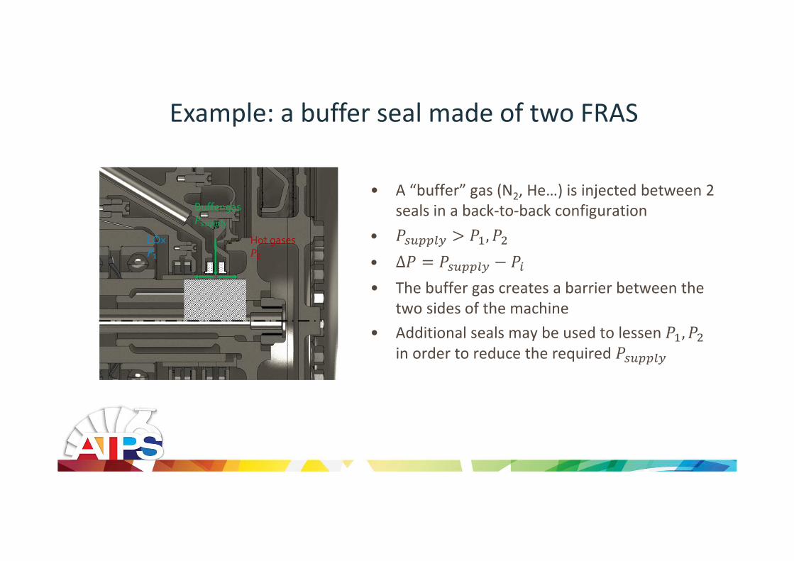
Example: a buffer seal made of two FRAS
• A “buffer” gas (N2, He…) is injected between 2
seals in a back-to-back configuration
• , • Δ • The buffer gas creates a barrier between the
two sides of the machine
• Additional seals may be used to lessen , in order to reduce the required

General description of the floating ring annular seal
• The carbon ring is mounted in a steel collar
• The main seal is a small radial clearance
between the annular faces ( 25µm)
• The pressure difference Δ presses the “nose” of the floating ring
against the stator and creates the secondary
seal
• The ring “floats” on the rotor and follows rotor
vibrations
• It allows large rotor excursions without using a
large clearance annular seal and therefore has a
limited leakage

State of the art of the scientific literature• R. G. Kirk and W. H. Miller, "The influence of high pressure oil seals on turbo-rotor stability," ASLE transactions, vol. 1, pp. 14-24, 1979.
• J. Semanate and L. San Andrés, "A quasi-static method for the calculation of lock-up speed in floating ring oil seals," in Proc. of the 4th Congreso
de Turbo-Maquinaria, Querrettara, Mexico, 1993, pp. 55-62.
• S. Baheti and R. G. Kirk, "Thermo-hydrodynamic solution of floating ring seals for high pressure compressors using the finite element method,"
STLE Tribology Transactions, vol. 37, pp. 336-349, 1994.
• T. W. Ha, Y. B. Lee, and C. H. Kim, "Leakage and rotordynamics analysis of a high pressure floating ring seal in the turbopump unit of a liquid
rocket engine," Tribology International, vol. 35, pp. 153-161, 2002.
• M. H. Nguyen, "Analyse des étanchéités annulaires à bague flottante" Poitiers, Thèse de doctorat 2011.
• M. Arghir, M. H. Nguyen, D. Tonon, and J. Dehouve, "Analytic Modeling of Floating Ring Annular Seals," J. Eng. Gas Turbines and Power, vol. 134,
no. 5, 2012.
• M., Arghir, M.-H., Nguyen, “Non-Linear Analysis of Floating Ring Annular Seals: Stability and Impacts”, Proceedings of the 9th IFToMM
International Conference on Rotor Dynamics, Milan, Italy, September 2014. DOI 10.1007/978-3-319-06590-8, pages 2007-2018.
• A. Mariot, "Analyse théorique et expérimentales des joints d’étanchéité à bague flottante et des joints rainurés segmentés " Poitiers, Thèse de
doctorat 2015.
• A., Mariot, M., Arghir, P., Hélies, J., Dehouve, J., “Experimental Analysis of Floating Ring Annular Seals and Comparisons with Theoretical
Predictions”, " J. Eng. Gas Turbines and Power, October 13, 2016, 138(4):042503-042503-9, doi: 10.1115/1.4031347.
• R. E. Burcham, "Liquid Rocket Engine Turbopump Rotating-Shaft Seals," NASA Lewis Research Center, Cleveland, Ohio, NASA SP-8121, 1978.
• R. E. Burcham, "High-speed crygoenic self-acting shaft seals for liquid rocket turbopumps," NASA Lewis Research Center, Cleveland, Ohio, NASA CR-168194, 1983.

Experimental analysis: first operating scenario
• The pressure difference Δ across the floating ring
increases with the rotation speed,
• For lower values of Δ, the floating ring “follows”
the rotor vibrations,
• As Δ increases, the vibration amplitudes of the
floating ring decrease because of the increasing
friction forces on the nose,
• For high values of Δ, the floating ring is “blocked”
and acts as an eccentric annular seal,
• There is a possibility of contacts between the rotor
and the carbon ring.

Experimental analysis: second operating scenario
• The pressure difference Δ remains limited,
• The floating ring is not locked,
• The behavior of the floating ring can be
periodic, quasi-periodic or chaotic.
There is still a possibility of contacts between the
rotor and the carbon ring if the eccentricity is too
high

The test rig: FRAS in back to back arrangement
Spindle Flexible coupling Housing
Rotor
Water injection Lomakin bearing
Rotor R
Rotor L
FRAS 1-4
Rotor
Additional
unbalance
FRAS
Cartridge Feeding
groove
The test rig houses 2 to 4 floating ring seals in a
back-to-back arrangement.
The displacements of the rotor and of the seals are
measured in 6 positions along 2 orthogonal directions , .The displacements are measured with inductive sensors.
The rotation speed, feeding pressure and mass flow rate
across the seal are measured.
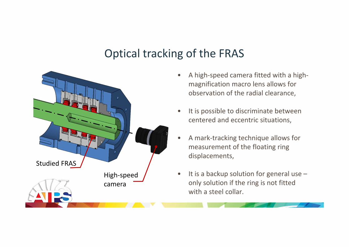
Optical tracking of the FRAS
High-speed
camera
Studied FRAS
• A high-speed camera fitted with a high-
magnification macro lens allows for
observation of the radial clearance,
• It is possible to discriminate between
centered and eccentric situations,
• A mark-tracking technique allows for
measurement of the floating ring
displacements,
• It is a backup solution for general use –
only solution if the ring is not fitted
with a steel collar.
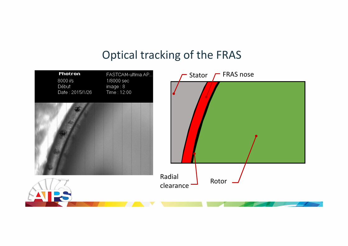
Optical tracking of the FRAS
Rotor
FRAS noseStator
Radial
clearance

Geometry of the seals and of the rotor
Conicity
NoseCollar
Axial flow
Seals: Rotor:
Cnom
+ 7 µm
Ideal shape
Real shape
• 38 mm diameter seals, 10 mm axial length
• 4 different seals, divided in two categories:
– Type 1 seals: small radial clearance ( 20µm),
low conicity (7µm)
– Type 2 seals: large radial clearance ( 30µm),
high conicity (15µm)

Experimental results: Ω=3000 rpm, ΔP=0.5 bar
Orb
its
Rotor L FRAS 1 FRAS 2 Rotor R
FRAS orbits are almost
circular (2x and 3x
spectral components
are low compared to 1x)
The rotor 3x
component is larger
than the 2x due to
runout errors
X F
FT
Remark: Y FFT are similar to X

Experimental results: Ω=3000 rpm, ΔP=1 bar
Orb
its
FRAS displacement
amplitudes
decrease with
increasing ∆P
Rotor L FRAS 1 FRAS 2 Rotor R
X F
FT
Remark: Y FFT are similar to X

Experimental results: Ω=3000 rpm, ΔP=1.5 bar
Orb
its
Locked Locked
FRAS are
locked!
X F
FT
Remark: Y FFT are similar to X
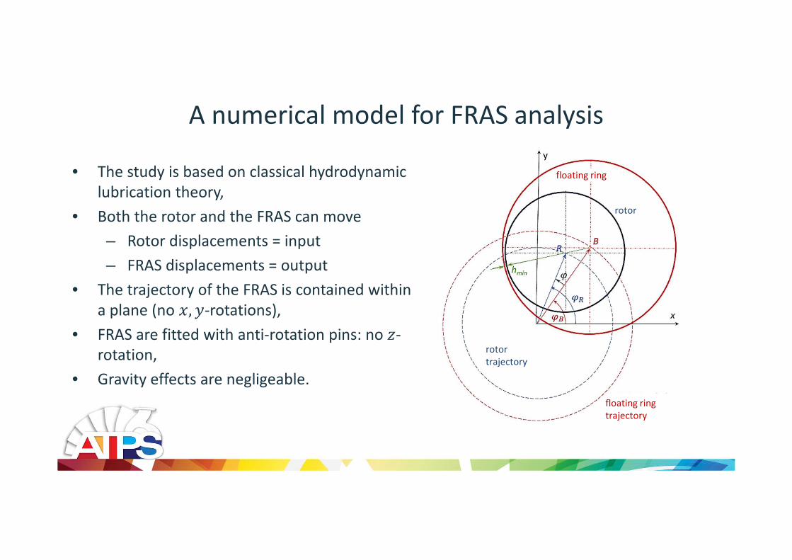
A numerical model for FRAS analysis
rotor
trajectory
floating ring
trajectory
rotor
floating ring • The study is based on classical hydrodynamic
lubrication theory,
• Both the rotor and the FRAS can move
– Rotor displacements = input
– FRAS displacements = output
• The trajectory of the FRAS is contained within
a plane (no , -rotations),
• FRAS are fitted with anti-rotation pins: no "-
rotation,
• Gravity effects are negligeable.

The equations of motion of the FRAS
• Forces on the floating ring:
– Axial force #$ due to the pressure
difference Δ (compensated by the
reaction force on the nose)
– Hydrodynamic forces #% in the main seal
– Friction forces #& on the nose of the FRAS
• Equations of motion:
' ()() #%,*#%, + #&,*
#&,Inertia forces
Hydrodynamic forces
Friction forces
"
#&#$
Δ, Ω, -
#%
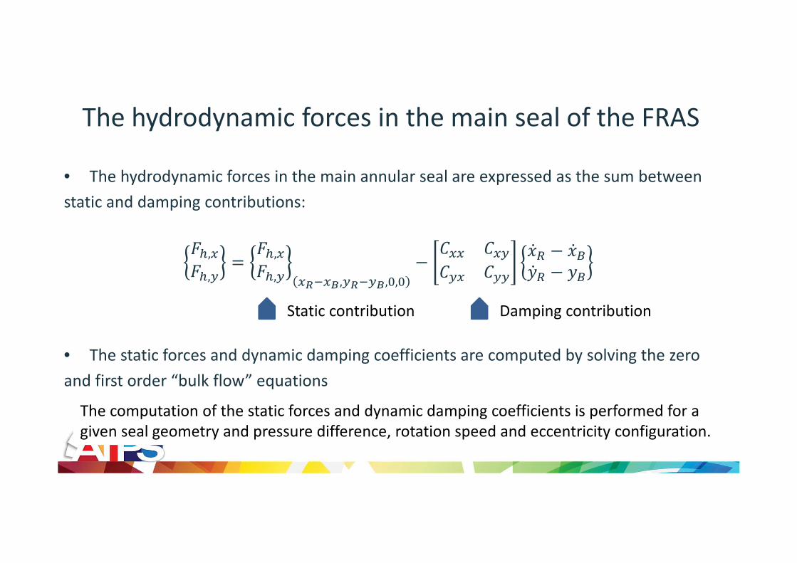
The hydrodynamic forces in the main seal of the FRAS
The computation of the static forces and dynamic damping coefficients is performed for a
given seal geometry and pressure difference, rotation speed and eccentricity configuration.
• The hydrodynamic forces in the main annular seal are expressed as the sum between
static and damping contributions:
#%,*#%, #%,*
#%, *./*0,./0,1,1 2** 2*
2* 234 3)34 )
• The static forces and dynamic damping coefficients are computed by solving the zero
and first order “bulk flow” equations
Static contribution Damping contribution

Friction forces on the nose of the FRAS
• The secondary seal is not completely closed: a
mixed lubrication regime subsists across the
nose
• Normal forces on the floating ring:
– Pressure difference
#$ 56 78 7 595 7 7– Hydrostatic contribution #$,&:– Asperity contact forces #$,5
• Balance of forces:
#$ #$,&: + #$,5 yields ;;
<
#$
#$,5#$,&

Contact forces: the contribution of asperities
Greenwood & Williamson’s model for the contact
between two rough surfaces:
• Contact between a nominally, rigid flat surface
and a rough, deformable surface
• Asperities in contact are modelled as
elastically loaded spheres of constant radius
#$,5 43>1?@∗ BC D " ; 8 ⁄ F " G"
HI
%;
<
#$
#$,5#$,&

Contact forces: hydrostatic contribution
;
<
#$
#$,5#$,&
• The flow in the secondary seal is modeled as a
1D, adiabatic channel flow (height ;, length <)
• The convective inertia effects are taken into
account (bulk flow equations):
4J&G"K% 1 L GL
MLN 1 + M 12 L
• The height of the canal is constant along the axial
direction: analytic solution
2J&"; P L P L
P L 1 LML + M + 1
2M ln M + 1 L2 + M 1 L
SST
UTU
H VWT XTYY
H VWT XYY
C ZZT
H VWT XTYYH VWT XY
Y

The equivalent friction coefficient on the nose of the FRAS
;
<
#$
#$,5#$,&
• The relation between #& and #$ can be
expressed thanks to an “equivalent coefficient
of friction” J:[:
#& J:[#$• Because of the hydrostatic contribution, the
coefficient of friction J:[ is lower than the
carbon/steel coefficient of friction
• J:[ depends on:
– Surface conditions and geometry
– Pressure difference
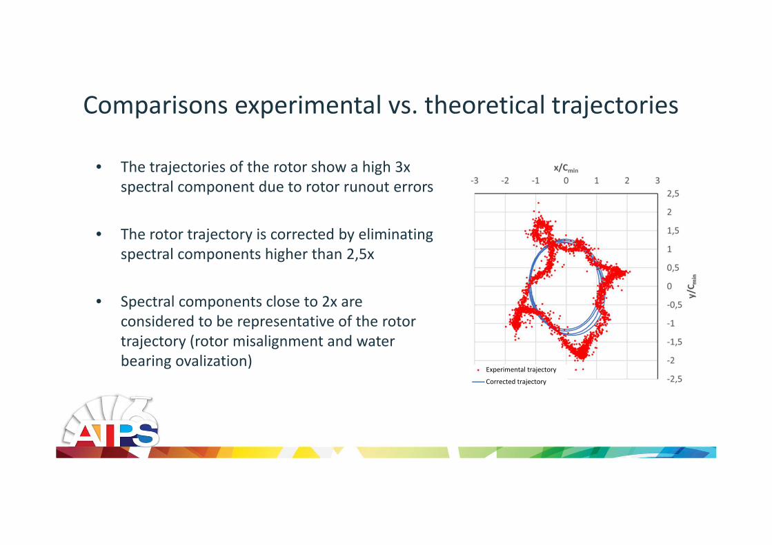
Comparisons experimental vs. theoretical trajectories
• The trajectories of the rotor show a high 3x
spectral component due to rotor runout errors
• The rotor trajectory is corrected by eliminating
spectral components higher than 2,5x
• Spectral components close to 2x are
considered to be representative of the rotor
trajectory (rotor misalignment and water
bearing ovalization)Experimental trajectory
Corrected trajectory
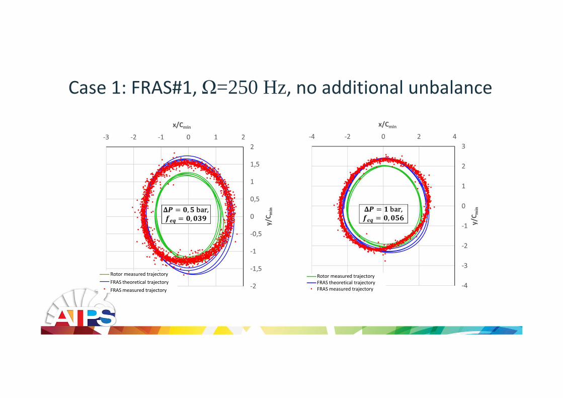
Case 1: FRAS#1, Ω=250 Hz, no additional unbalance
Rotor measured trajectory
FRAS theoretical trajectory
FRAS measured trajectory
Rotor measured trajectory
FRAS theoretical trajectory
FRAS measured trajectory
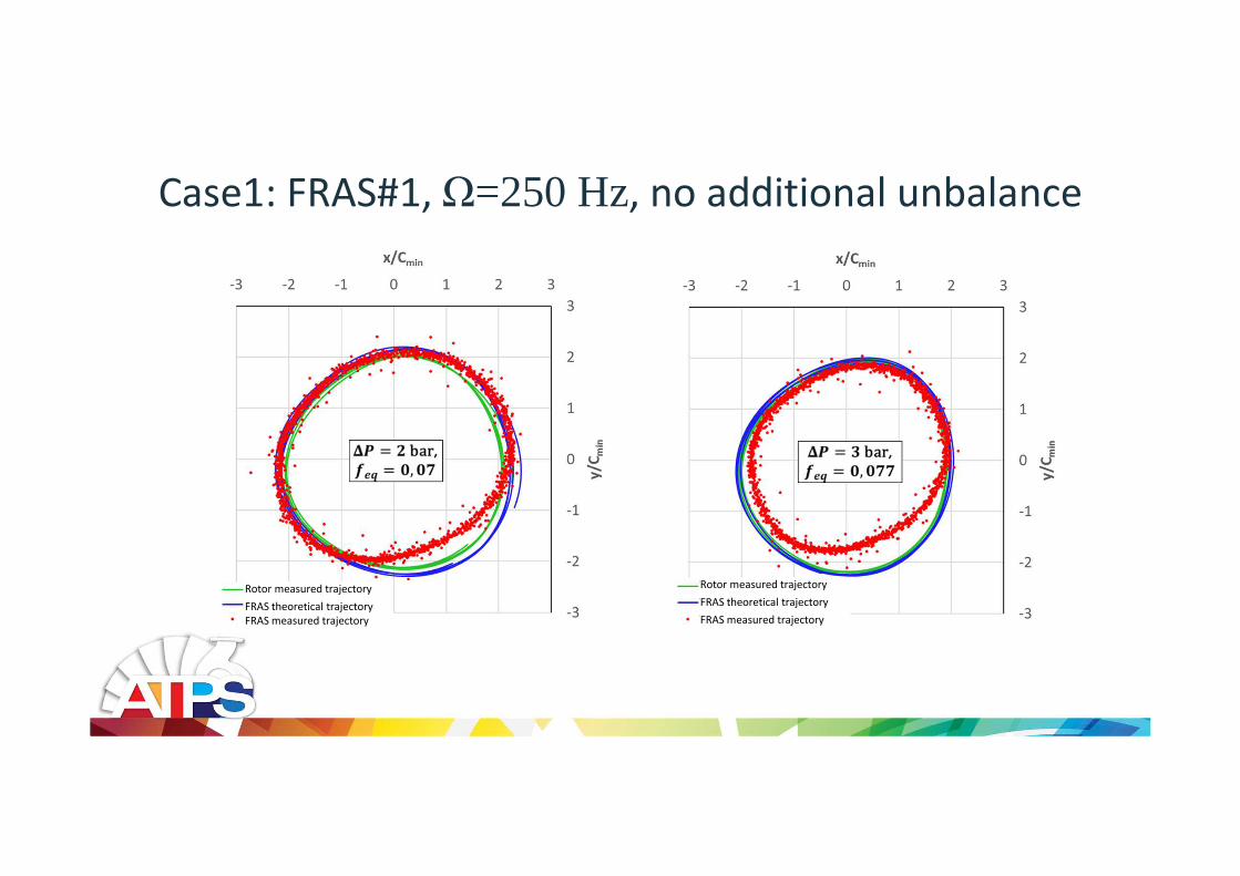
Case1: FRAS#1, Ω=250 Hz, no additional unbalance
Rotor measured trajectory
FRAS theoretical trajectory
FRAS measured trajectory
Rotor measured trajectory
FRAS theoretical trajectory
FRAS measured trajectory

Results for FRAS#1, Ω=250 Hz, no additional unbalance
Experimental leakage
Predicted
leakage
• The numerical model predicts closely the
behavior of the seal
• The predicted eccentricity is 40% and is
constant with increasing Δ (theoretical
minimum film thickness is 8µm )
• No predicted contact between the seal and
the rotor
• The agreement between the predicted and
experimental leakage rates accross the seal
cartridge is good

Case 2: FRAS#1, Ω=250 Hz, 25 g∙mm additional unbalance
Rotor measured trajectory
FRAS theoretical trajectory
FRAS measured trajectory
Rotor measured trajectory
FRAS theoretical trajectory
FRAS measured trajectory
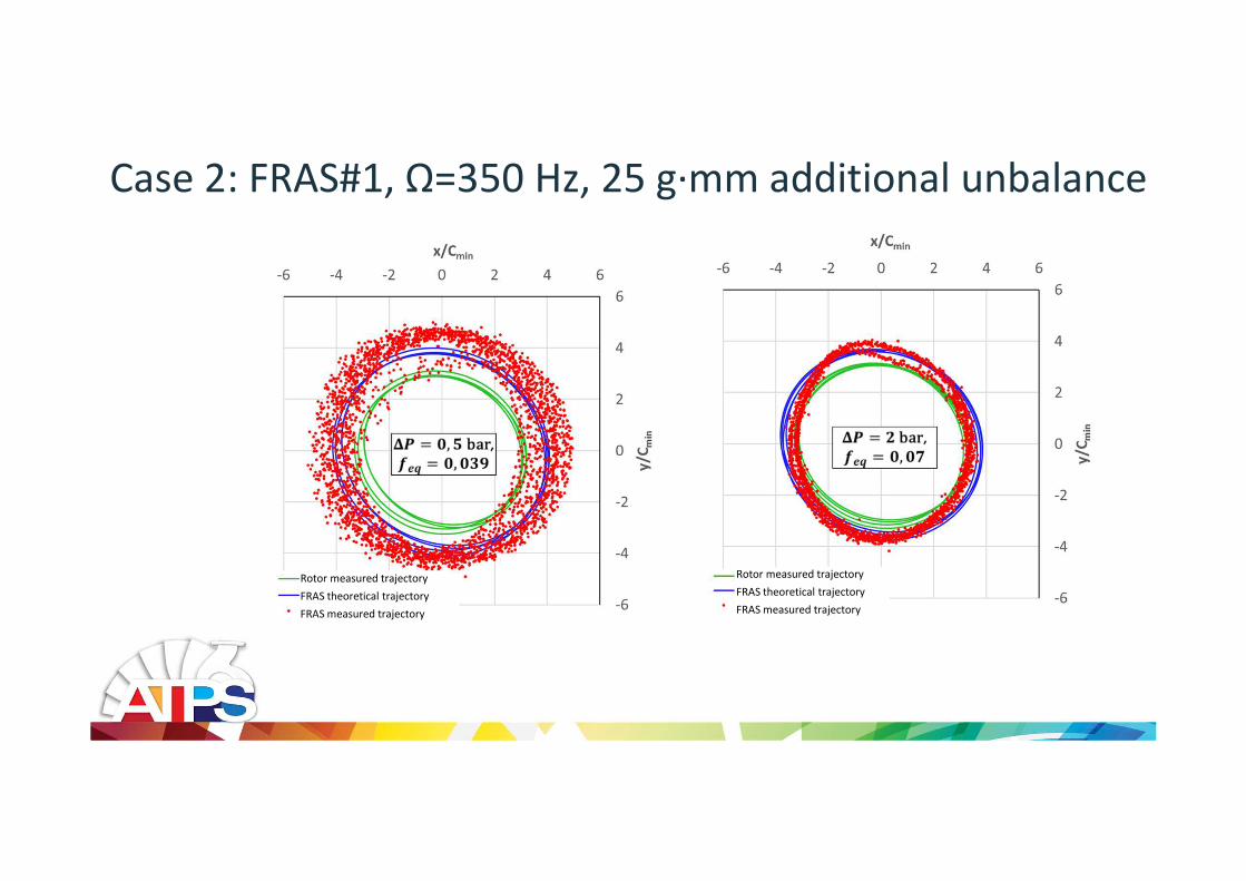
Case 2: FRAS#1, Ω=350 Hz, 25 g∙mm additional unbalance
Rotor measured trajectory
FRAS theoretical trajectory
FRAS measured trajectory
Rotor measured trajectory
FRAS theoretical trajectory
FRAS measured trajectory
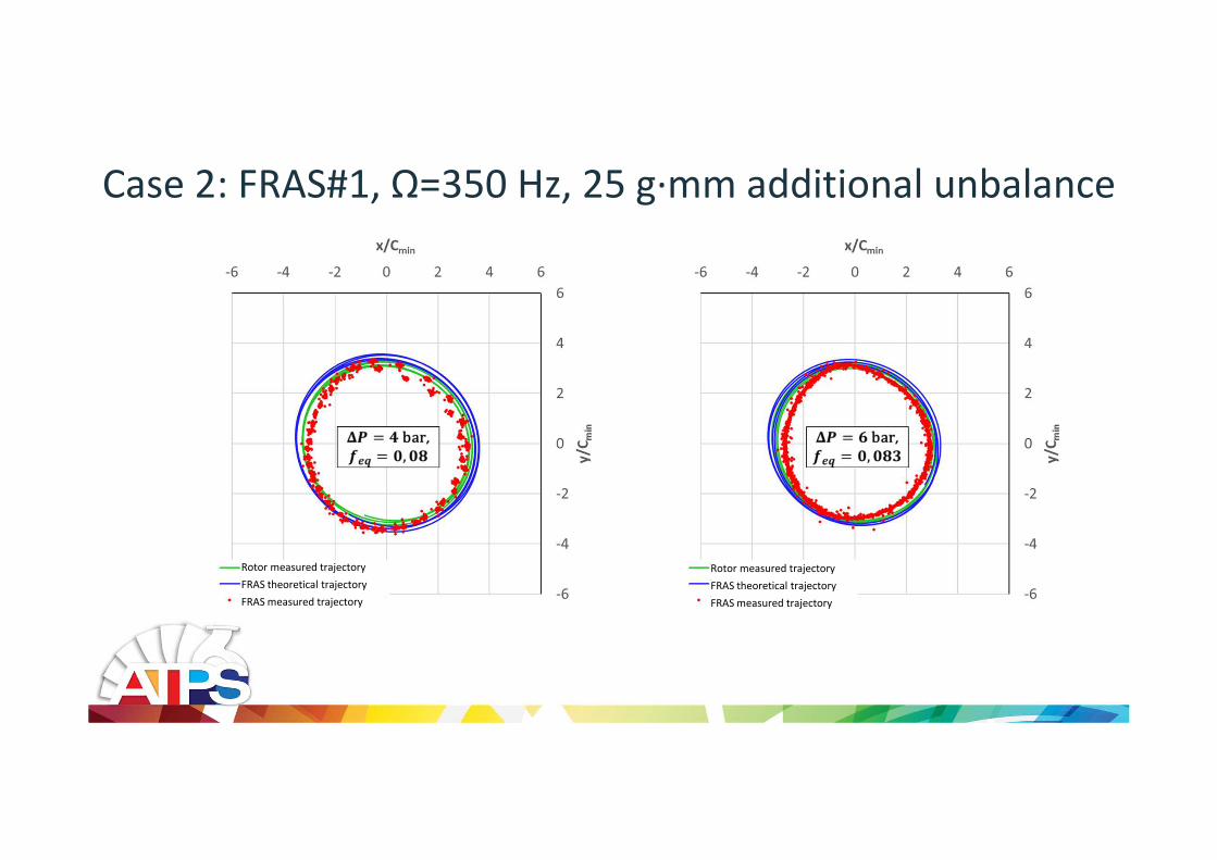
Case 2: FRAS#1, Ω=350 Hz, 25 g∙mm additional unbalance
Rotor measured trajectory
FRAS theoretical trajectory
FRAS measured trajectory
Rotor measured trajectory
FRAS theoretical trajectory
FRAS measured trajectory

Case 2: FRAS#1, Ω=350 Hz, 25 g∙mm additional unbalance
Predicted
leakage
Experimental leakage
• Again, the numerical model predicts closely
the behavior of the seal
• The predicted eccentricity varies between 40and 70% and decreases with increasing
Δ(predicted minimum film thickness is 0 to
10µm )
• Possibility of contacts even though the seal is
not locked
• The agreement between the predicted and
experimental leakage rates accross the seal
cartridge is good

Case 3: FRAS#2,no additional unbalance
Ω=350 Hz Ω=250 Hz
Rotor measured trajectory
FRAS theoretical trajectory
FRAS measured trajectory
Rotor measured trajectory
FRAS theoretical trajectory
FRAS measured trajectory
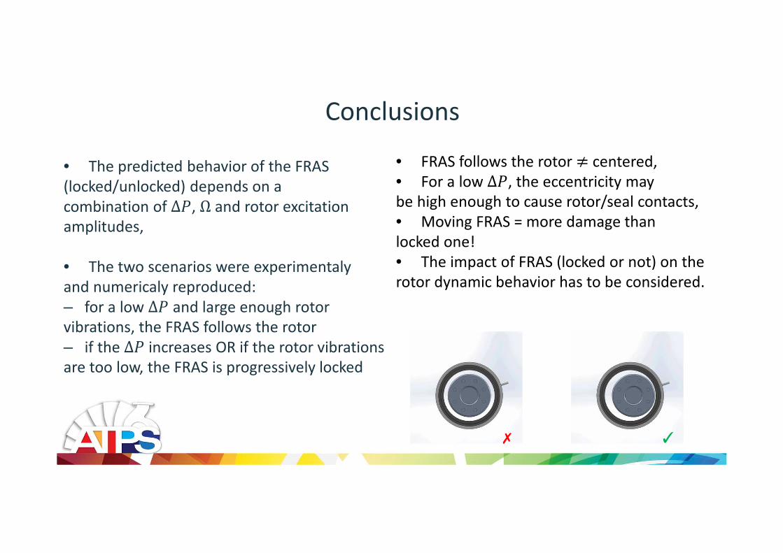
Conclusions
• The predicted behavior of the FRAS
(locked/unlocked) depends on a
combination of Δ, Ω and rotor excitation
amplitudes,
• The two scenarios were experimentaly
and numericaly reproduced:
– for a low Δ and large enough rotor
vibrations, the FRAS follows the rotor
– if the Δ increases OR if the rotor vibrations
are too low, the FRAS is progressively locked
• FRAS follows the rotor ^ centered,
• For a low Δ, the eccentricity may
be high enough to cause rotor/seal contacts,
• Moving FRAS = more damage than
locked one!
• The impact of FRAS (locked or not) on the
rotor dynamic behavior has to be considered.

Thank you!
Questions?