* Corresponding author e-mail: [email protected] Journal access: www.adpublication.org Tel.: +91 9429926405 © 2016 A D Publication. All rights reserved ID:IJFTE2015V02I0310001 Volume 2 Issue 3,September 2016
International Journal of
Fluid and Thermal Engineering A Peer-reviewed journal IJFTE 07 (2016) 001-007
Numerical analysis of exhaust emission for combustion chamber of
gas turbine power plant
Nikul Patel 1*, Vimal Patel 2
1,2
Department of Mechanical Engineering, Faculty of Technology & Engineering, The Maharaja Sayajirao University of Baroda, Vadodara, Gujarat, India
A B S T R A C T : Combustion chamber is used to burn fuel-air mixture to produce energy. This energy are then supply to enter the nozzle and then into the turbine. Current state-of-the-art in Computational Fluid Dynamics (CFD) provides reasonable reacting flow predictions and is already used in industry to evaluate new concepts of gas turbine engines. In parallel, optimization techniques have reached maturity and several industrial activities benefit from enhanced search algorithms. The numerical simulation of can type combustion chamber for utran power plant is carried out using commercial CFD code CFX. Turbulence is modeled using k-ε turbulence model. For the liner flow, it is observed that on moving axial from inlet to outlet, velocity, temperature contours become more uniform symmetric in circumference plane. Mass fraction CH4 and O2 decreases where concentration of CO2, increases in the axial direction. Different boundary condition are applied for find out the required exit temperature and reduced nitric oxide (NO) in parts per million. Changes geometry finds out require exit temperature and produced less emission NO, CO2. Variation of number of elements in mesh studied the different parameter effect increase the number of element. Variation of different mass fraction likes CH4, O2, CO2, and temperature, velocity along center line axial direction form inlet to outlet and also graphs are plotted. © 2015 A D Publication. All rights reserved
Keywords:
Combustion Chamber, Gas turbine, nozzle, emission
1. Introduction
Air-craft gas turbine combustor technology has been developing gradually and continuously, rather than a
dramatic change. The basic geometry of combustor is derived by the need for its length and frontal area to
remain within limits set by other engine components, the necessity of a diffuser is to minimize pressure loss, and
the requirement of a liner to provide stable operation over a wide range of air-fuel ratios. In spite of more a
arduous operating condition like high pressure, temperature, and inlet velocity these days combustors continue
to exhibit 100 percent combustion efficiency over the normal working range, demonstrate substantial reductions
in pressure loss and pollutant emission, and allow a linear life that is significantly longer than those of many
other engine components. As gas turbine technology advances into 21st century; combustion engineers are
faced with the challenges of achieving of higher compression ratios, higher turbine inlet temperature in aero gas
turbine engines. At the same time, as interest in pollutant emissions from gas turbine increases, combustion
engineers are also required to consider new means for pollutant reduction. The desired performance
requirement, in terms of higher engine thrust ratio and lower specific fuel consumption will call for higher turbine
inlet temperatures and closer adherences to the design temperature profile at the turbine inlet. At the same time

N K Patel et al / International Journal of Fluid and Thermal Engineering
Page | 2
the demand for greater reliability, increased durability, and lower manufacturing, development and maintenance
costs seems likely to assume added importance in the future. To meet these challenges, designers have
searched for concept that would simplify both the basic design data and methods of fabrication. This searched
for concept that would simplify both the basic design data and method of fabrication. This search has lead to the
development of advanced cooling configurations and the increased use of refractory coatings within the
combustion system. Figure 1 (a) shows a simple cycle gas turbine which has main three component (1)
compressor (2) combustor (3) turbine. Figure 1 (b) shows a conventional “pressure-volume” diagram for a gas
turbine, in which it shows that between the compressor and the turbine there is a stage where air expands at
constant pressure. This expansion is achieved through heating of air by injection and the following combustion
of a hydrocarbon fuel in a device that is commonly described as a combustor or chamber. The work output of
the gas turbine is directly related to the area enclosed within the pressure-volume diagram. Thus a large degree
of expansion that is, a barge horizontal separation of points 2 and 3 in figure 1 (b), will give a large amount of
work. However, since the gas is being expanded by raising its temperature, a practical limit is set by the
maximum temperature the material of the engine components located at the outlet of the combustor, notably the
turbine blades can accept. In actual process a pressure loss is always incurred.
(a) (b) (c)
Figure 1 P-V and T-S diagram for a simple gas turbine
An important design objective is to keep this pressure loss as low as possible, since at reduction in the area
of the pressure-volume diagram constitutes a loss in engine power output. Other important combustor design
requirements are high combustion efficiency, reliable and smooth ignition, wide stability limits, low pollutant
emission and outlet temperature distribution. Heat input to the gas turbine cycle is provided by a combustor. Air
enters combustor from the compressor which is delivered at elevated temperature to the turbine (ideally with no
pressure loss). Thus, the combustor is a direct-fired air heater in which fuel is burned almost stoichiometrically
with one third or less of the compressor discharge air. Combustion products are then mixed with the remaining
air to arrive at a suitable turbine inlet temperature. There are many types of combustor, but the three major
types are tubular, turbo-annular, and annular. Despite the any design differences, all gas turbine combustion
chambers have three features A recirculation zone, A burning zone (with a recirculation zone which extends to
the dilution region) and A dilution zone. The function of the recirculation zone is to evaporate, partly burn, and
prepare the fuel for rapid combustion within the remainder of the burning zone. Ideally, at the end of the burning
zone, all fuel should be burnt so that the function of the dilution zone is solely to mix the hot gas with the dilution
air. The mixture leaving the chamber should have a temperature and velocity distribution acceptable to the
guide vanes and turbine. Generally, the addition of dilution air is so abrupt that if combustion is not complete at
the end of the burning zone, chilling occurs and prevents completion. However, there is evidence with some
chambers that if the burning zone is run over rich, some combustion does occur within the dilution region.
Combustor inlet temperature depends on engine pressure ratio, load and engine type, and whether or not the
turbine is regenerative or non-regenerative especially at the low-pressure ratios. The new industrial turbine
pressure ratios are between 17:1 and 35:1, which means that the combustor inlet temperatures range from

N K Patel et al / International Journal of Fluid and Thermal Engineering
Page | 3
454°C to 649°C. Fuel rates vary with load, and fuel atomizers may be required for flow ranges as great as
100:1. The loss of pressure in a combustor is a major problem; since it affects both the fuel consumption and
power output; total pressure loss is usually in the range of 2-8 % of static pressure. This loss is the same as a
decrease in compressor efficiency. The result is increased fuel consumption and lower power output that affect
the size and weight of the engine. The average inlet temperature to the turbine affects both fuel consumption
and power output. A large combustor outlet gradient will work to reduce averages gas temperature and
consequently reduce power output and efficiency. Some factors are very important that affects satisfactory
operation and life of the combustor. To achieve satisfactory operation, the flame must be self-sustaining, and
combustion, must be stable over a range of fuel-to-air ratios to avoid ignition loss during transient operation.
Minimum carbon deposits and smoke emissions also help assure satisfactory operation.
2. Modelling, Meshing and Simulation
The aerodynamic process plays a vital role in the design and performance of a gas turbine combustion
system. The flow in the combustion chamber is generally complex, due to highly turbulent nature of the flow
field, coupled with complex geometric configuration. Further, the additional complications of combustion like fuel
evaporation, radiative and convective heat transfer, and chemical kinetics are also involved. The interaction
between the diffuser and the combustor external flows plays a key role in controlling the total- pressure
loss, flow distribution around the combustor liner, durability, and stability. All dimensions of the can type
combustion chamber of utran gas power plant was taken from the site. As shown in figure 2 is the actual inner
liner of the combustion chamber. Figure 3 shows total length of the inner liner is 702 mm. the inner liner
combustion chamber have a first two row is primary hole, third one row intermediate hole and Last one row is
dilution hole. As shown in fig 3 First row number of 8 hole is 20 mm, second row number of 8 hole is 15 mm,
third row number of 8 hole is13 mm, and dilution hole row is 45 mm.
Figure 2 Inner Liner Combustion Chamber
N K Patel et al / International Journal of Fluid and Thermal Engineering
Page | 4
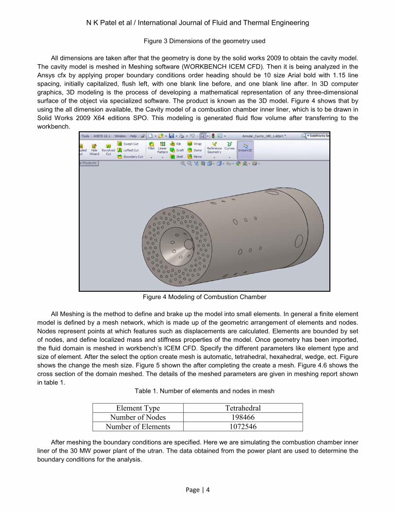
Figure 3 Dimensions of the geometry used
All dimensions are taken after that the geometry is done by the solid works 2009 to obtain the cavity model.
The cavity model is meshed in Meshing software (WORKBENCH ICEM CFD). Then it is being analyzed in the
Ansys cfx by applying proper boundary conditions order heading should be 10 size Arial bold with 1.15 line
spacing, initially capitalized, flush left, with one blank line before, and one blank line after. In 3D computer
graphics, 3D modeling is the process of developing a mathematical representation of any three-dimensional
surface of the object via specialized software. The product is known as the 3D model. Figure 4 shows that by
using the all dimension available, the Cavity model of a combustion chamber inner liner, which is to be drawn in
Solid Works 2009 X64 editions SPO. This modeling is generated fluid flow volume after transferring to the
workbench.
Figure 4 Modeling of Combustion Chamber
All Meshing is the method to define and brake up the model into small elements. In general a finite element
model is defined by a mesh network, which is made up of the geometric arrangement of elements and nodes.
Nodes represent points at which features such as displacements are calculated. Elements are bounded by set
of nodes, and define localized mass and stiffness properties of the model. Once geometry has been imported,
the fluid domain is meshed in workbench’s ICEM CFD. Specify the different parameters like element type and
size of element. After the select the option create mesh is automatic, tetrahedral, hexahedral, wedge, ect. Figure
shows the change the mesh size. Figure 5 shown the after completing the create a mesh. Figure 4.6 shows the
cross section of the domain meshed. The details of the meshed parameters are given in meshing report shown
in table 1.
Table 1. Number of elements and nodes in mesh
After meshing the boundary conditions are specified. Here we are simulating the combustion chamber inner
liner of the 30 MW power plant of the utran. The data obtained from the power plant are used to determine the
boundary conditions for the analysis.
Element Type Tetrahedral Number of Nodes 198466
Number of Elements 1072546

N K Patel et al / International Journal of Fluid and Thermal Engineering
Page | 5
Boundary condition calculation from RQL theory
Data from the utran power station (current working condition)
Gas flow to = 2.403 kg/sec
Fuel gas pressure = 18.64 kg/cm2
Fuel gas temperature = 100°C
Compressor air exit temperature = 84°C
Compressor air exit pressure = 9 bar
Mass flow rate of air Ma (total) = 11.34 kg/sec
Mass flow rate of fuel Mf = 0.24 kg/sec
Velocity of fuel = 39.93 m/sec
Mass flow rate fuel air ratio (Mf/Ma) actual = 0.0212
Figure 5 Meshing [ANSYS ICEM CFD]
Burning of fuel inside the combustion chamber leads to generation of high flame temperature. As the
temperature at the end of the combustion is having limitation by the material used in turbine blades. The peak
gas temperature should be in the primary reaction zone and thereafter the gas temperature decreases after the
primary reaction zone due to the dilution of the flame with the secondary air.

N K Patel et al / International Journal of Fluid and Thermal Engineering
Page | 6
Figure 6 Profile Of Temperature Along Center Line Figure 7 Profile of CH4 mass fractions along center line
Figure 8 Profile of O2 mass fractions along center
line
Figure 9 Profile of CO2 Mass Fractions along Center
Line
As shown in figure 6 the temperature is varying from inlet to the exit of combustion chamber and it is observed
that exit temperature is 1230 K. This temperature is maintained so that turbine blade has no effect. Fuel injected
in the combustion chamber is methane. Complete combustion of fuel is must in any combustion process as it
will lead to less emission. Methane combustion is a chemical reaction that occurs from burning methane gas
which is an odorless and colorless fossil fuel causing high amounts of heat and pressure to be produced.
Methane by itself cannot be caused to burn effectively without using oxygen as an additive. This combination is
what causes methane to begin burning, which is called methane combustion. What is the variation in quantity of
fuel as it progress in the combustion process is very difficult to visualize practically but with the help of
simulation we can find what mass fraction of fuel is burnt and what is remain as combustion progresses. We can
clearly observe that value of mass fraction is higher near to fuel injection zone because, pure fuel is injected
there. But we move along center line of combustor, its concentration will significantly reduce due to more and
more methane will utilize for combustion Figure 7 shows that at axial distance z=350 mm which representing
downstream of secondary air inlet zone, value of mass fraction of methane is approaching to zero. At outlet of
combustor CH4 value is also zero. This indicate that complete combustion has done, there is no fuel present at
that region. Shown in figure 8 It is quite observe that concentration of O2 is higher at exit region of combustor
compare to center region because of air as oxidant entering from secondary air inlet region and air composition
by weight it contains 23.2 % O2 and 76.8 % N2. At center region its value is zero up to axial distance z=300 mm
the upstream region of secondary air inlet, further movement after the region of secondary air inlet, increment in
mass fraction of O2 significantly due to more and more air is introduced from the secondary air inlet holes. O2
increased in exit condition gradually. Carbon dioxide is a product of the combustion process, and it is primarily
mitigated by reducing fuel usage. Carbon dioxide emissions will continue to drop as manufacturers make gas
turbine engines more efficient. It is afraid that the atmospheric temperature might be increased on account of
the greenhouse effect by CO2 and the climate might be changed on global scale. Hence it is required to reduce
the emission of CO2 into the atmosphere. Shown in Figure 9 the carbon dioxide (CO2) produce when the
burning the fuel and after the gradually decrease to exit condition.
Conclusion
The utran power plant working boundary condition apply of Rich Burn Quick Mix Lean Burn inner liner for
N K Patel et al / International Journal of Fluid and Thermal Engineering
Page | 7
combustion chamber is carried out using methane as a fuel as part of development of can type inner liner
combustion chamber and the model is verified using Numerical exit temperature and plant exit temperature. The
qualitative agreement of CFD result with result suggests that the basic assumptions & boundary condition for
CFD analysis can be applied to understand the flow phenomena, temperature, CH4, O2, CO2, for combustion
chamber.
Reference
[1] Hassa C., Miguels C.E. and Voight P.,”Design Principle of Quick Zone of RQL Combustors”, German Aero Space
Centre, DLR, P.P Box 90 60 58 Institute Of Propulsion Technology, D-51170 Köln, Germany May 1998. [2] Christopher O Peterson, William A.sowa, G.S.samuelsen, “performance of a model RQL combustor at elevated
temperature and pressure”, University of California, National Aeronautics and space administration December 2002 [3] Kulshreshtha D. B, Channiwala S. A, Chaudhari K. V & Dikshit S. B, “Design, Numerical Simulation and
Experimental Investigations on Can-Annular Type Combustion Chamber for 20 kW Gas Turbine Engine”, International Journal of Dynamics of Fluids, Vol. 4, No. 2, pp. 175 - 189, 2008.
[4] S N Singh, V Seshadri, R K Singh and T Mishra, “Flow characteristic of an annular gas turbine combustor model for reacting flow using CFD”, Journal of scientific & industrial research, vol. 65, pp. 921-934.
[5] Cameretti, M.C., and Tuccillo, R., “Comparing Different Solutions for the Micro-Gas Turbine Combustor”, ASME paper GT 2004-GT-53286.
[6] Dr. S. A. Channiwala & Dr. Digvijay Kulshreshtha, “Numerical simulation approach as design optimization for micro combustion chambers”, Tenth International Congress of Fluid Dynamics, December 16-19, 2010.
[7] Paolo Gobbato, Massimo Masi, Andrea Toffolo, Andrea Lazzaretto, Giordano Tanzini, “Calculation of the ow eld and NOx emissions of a gas turbine combustor by a coarse computational uid dynamics model” 10 December 2011.
[8] Kulshreshtha D. B & Channiwala S. A, “Numerical Simulation to Study the Effect of Divergence Angles on Performance of Inlet Diffuser Section of a Gas Turbine Combustor”, ICCMS 06, IIT Guwahati, 2006.
[9] Lefebvre A. H. and Halls G. A., “Some Experiences in Combustion Scaling, AGARD Advanced Aero Engine Testing”, AGARD graph 37, 1959, pp.177-204.
[10] Alessandro Marini, Alessandro Cappelletti, Giovanni Riccio, Francesco Martelli, “CFD re-design of a gas turbine can-type combustion chamber hydrogen fired”, V European Conference on Computational Fluid Dynamics, ECCOMAS CFD 2010
[11] Stevan Nemoda, Vukman Bakic, Simeon Oka, Goran Zivkovic, Nenad Crnomarkovic, “Experimental and numerical investigation of gaseous fuel combustion in swirl chamber”, International Journal of Heat and Mass Transfer 48 (2005) 4623–4632.
[12] Lefebvre, A.H., 2000, “Gas Turbine Combustion”, ed. Taylor & Francis.


![PERFORMANCE, EMISSION, AND COMBUSTION ......tion pressure. Alptekin et al.[2] tested the effect on engine performance, combustion charac-teristics, and exhaust emissions of using waste](https://static.cupdf.com/doc/110x72/5fe4282d8c8e9c10e8526db6/performance-emission-and-combustion-tion-pressure-alptekin-et-al2.jpg)


![UNCLASS]IED IIIIIIII EMISSION PERFORMANCE COMBUSTION ... · ad-a161 652 performance combustion ch4aracteristics and exhaust 1/2 emission of a direct i (u) north carolina state univ](https://static.cupdf.com/doc/110x72/5f927a6d1c7dfa5c2e7736ac/unclassied-iiiiiiii-emission-performance-combustion-ad-a161-652-performance.jpg)