i
Northrop Grumman Handling Arm
Final Report
Savannah Hillebrand
Rayne Dobson
Keven Benavente
Samantha Scarcello
Tyler Schafer
David McNealy
2018-2019
Project Sponsor: Northrop Grumman Corporation
Faculty Advisor: Sarah Oman
Sponsor Mentor: Steven Hengl
ii
DISCLAIMER
This report was prepared by students as part of a university course requirement. While considerable effort
has been put into the project, it is not the work of licensed engineers and has not undergone the extensive
verification that is common in the profession. The information, data, conclusions, and content of this report
should not be relied on or utilized without thorough, independent testing and verification. University faculty
members may have been associated with this project as advisors, sponsors, or course instructors, but as
such they are not responsible for the accuracy of results or conclusions.

iii
EXECUTIVE SUMMARY
This report is to document the design process of a brand-new articulating handling arm for the purpose of
supporting assembly and testing processes of avionic systems. The client, Northrop Grumman, has
requested a benchtop-mountable articulating arm that is capable of supporting an entire avionics system so
the operators do not have to hold the system themselves. Northrop Grumman Corporation (NGC) does not
currently have any type of avionics support system in place. Avionic systems are very expensive and
currently, these systems have been dropped, rendering the entire system damaged and useless. A handling
arm device would allow the avionics system to be supported without concern of being dropped. The team
was tasked with designing a benchtop-mountable articulating handling arm capable of having six degrees
of freedom, hold a 15 pound system, and withstand a 20 pound force of an operator. Additionally, NGC
required that the handling arm be tested to 125% of their specifications and pass with a factor of safety of
3. The team has successfully come up with a design and performed analysis to confirm requirements are
met. More specific requirements regarding weight and size restraints are further discussed in this report.
To create a handling arm that meets or exceeds all customer requirements, the team came up with a
functional design. A modified C-clamp will secure the system to a bench top with expanded plates on the
underside of the table top for added security. A vertical tube will be welded to the top of the c-clamp,
featuring a rack and pinion system that allows the horizontal arm to rotate around the vertical tube. Two
horizontal links extend out from the tube, supported by a shock system. A locking mechanism will be fixed
to the two shock systems in order to lock out the components for a more stable environment for the user.
Different head attachments will be available to allow the user more control over how the avionics system
is situated. A bolt pattern head and a flexible finger head will both be available for this purpose. All
components will be made of 304 Stainless Steel. The overall cost of this mechanism is just under $2,900,
well within the $9,500 max budget.
After many iterations and design changes, as well as analyses to further ensure a quality design, a final
design has been created. The system will undergo manufacturing and further testing in the coming semester
to ensure the build meets all customer requirements. Once the arm has successfully been built and
adequately tested, the design and constructed system will be handed over to NGC for them to implement
onto their shop floor.

iv
ACKNOWLEDGMENTS
The design team would like to thank everyone who was able to make this project happen. First, Steven
Hengl, the team’s client, from Northrop Grumman. He has given the team the opportunity to apply the years
of skills and knowledge in engineering classes to a real-world scenario. He has also been available to help
with any issues that have come up along the way. The team would also like to thank Dr. Sarah Oman, the
team’s Capstone professor at Northern Arizona University, for guiding the team along the way with the
design process. The team would also like to thank Stephen Smart, an operator within Northrop Grumman,
for getting the team information on the tables that the Handling Arm will attach to. Lastly, Dr. Amir Arzani
was a significant help to the team, assisting with the table clamp analysis. Without the help of the people
listed above, the team would not be able to accomplish this project.

v
TABLE OF CONTENTS
Contents DISCLAIMER .............................................................................................................................................. ii EXECUTIVE SUMMARY .......................................................................................................................... iii ACKNOWLEDGMENTS ........................................................................................................................... iv TABLE OF CONTENTS .............................................................................................................................. v 1 BACKGROUND ................................................................................................................................ 1
1.1 Introduction .............................................................................................................................. 1 1.2 Project Description ................................................................................................................... 1 1.3 Original System ........................................................................................................................ 1
2 REQUIREMENTS ............................................................................................................................. 2 2.1 Customer Requirements (CRs) ................................................................................................. 2 2.2 Engineering Requirements (ERs) ............................................................................................. 2 2.3 Testing Procedures .................................................................................................................... 4
2.3.1 Safety .......................................................................................................................... 4 2.3.2 ESD Compliant ........................................................................................................... 4 2.3.3 Load Capacity ............................................................................................................. 5 2.3.4 Component Size .......................................................................................................... 5 2.3.5 Torque ......................................................................................................................... 5 2.3.6 Degrees of Freedom .................................................................................................... 5 2.3.7 Longevity of Components ........................................................................................... 5 2.3.8 Structural Integrity ...................................................................................................... 5 2.3.9 Compatible with Table ................................................................................................ 5 2.3.10 Device Weight ......................................................................................................... 6 2.3.11 Cost ......................................................................................................................... 6
2.4 House of Quality (HoQ) ........................................................................................................... 6 2.4.1 Main Room (CRs to ERs) ........................................................................................... 6 2.4.2 Basement (Absolute Technical Importance) ............................................................... 6 2.4.3 Attic (ERs to ERs)....................................................................................................... 6
3 EXISTING DESIGNS ........................................................................................................................ 7 3.1 Design Research ....................................................................................................................... 7 3.2 System Level ............................................................................................................................ 7
3.2.1 Existing Design #1: Tablet Mount .............................................................................. 7 3.2.2 Existing Design #2: Computer Monitor Mount .......................................................... 8 3.2.3 Existing Design #3: Robotic Arm Kit ......................................................................... 8
3.3 Functional Decomposition ........................................................................................................ 9 3.3.1 Black Box Model ........................................................................................................ 9 3.3.2 Functional Model/ Hierarchical Task Analysis ........................................................... 9
3.4 Subsystem Level ..................................................................................................................... 11 3.4.1 Subsystem #1: Table Attachments............................................................................. 11 3.4.2 Subsystem #2: Mechanical Joints ............................................................................. 12 3.4.3 Subsystem #3: Head Attachments ............................................................................. 14 3.4.4 Subsystem #4: Locking Mechanism ......................................................................... 15
4 DESIGNS CONSIDERED ............................................................................................................... 18 4.1 Design #1: Bio-Inspired Leg Springs ..................................................................................... 18 4.2 Design #2: Clamped Shock Assisted Central Locking Arm ................................................... 19 4.3 Design #3: Bolt-Pattern Mount Head ..................................................................................... 20 4.4 Design #4: Hydraulically Assisted Arm ................................................................................. 20 4.5 Design #5: Clamped Shock Assisted Arm .............................................................................. 21
vi
5 DESIGN SELECTED – First Semester ............................................................................................ 23 5.1 Rationale for Design Selection ............................................................................................... 23
5.1.1 Pugh Chart ................................................................................................................ 23 ................................................................................................................................................ 24 5.1.2 Decision Matrix......................................................................................................... 24
5.2 Design Description ................................................................................................................. 25 5.3 Design Subsystems ................................................................................................................. 26
5.3.1 Table Attachment ...................................................................................................... 26 5.3.2 Mechanical Joints ...................................................................................................... 27 5.3.3 Head Attachments ..................................................................................................... 27 5.3.4 Locking Mechanism .................................................................................................. 28
5.4 Design Modifications ............................................................................................................. 29 6 PROPOSED DESIGN ...................................................................................................................... 30
6.1 Bill of Materials ...................................................................................................................... 30 6.2 Schedule ................................................................................................................................. 30 6.3 CAD Package ......................................................................................................................... 31
7 REFERENCES ................................................................................................................................. 33 8 APPENDICES .................................................................................................................................. 35
8.1 Appendix A: House of Quality ............................................................................................... 35 8.2 Appendix B: Supplemental Designs Considered (6-10) ......................................................... 36
8.2.1 Adjustable Wrench Design ........................................................................................ 36 8.2.2 C-Clamp Mount Plate Design ................................................................................... 36 8.2.3 Dual Joint Removable Head Design ......................................................................... 37 8.2.4 Bio-Inspired Hawk Beak ........................................................................................... 38 8.2.5 Rolling Joint Claw .................................................................................................... 39
8.3 Appendix C: Bill of Materials ................................................................................................ 40 8.4 Appendix D: Spring Semester Schedule ................................................................................ 41
1
1 BACKGROUND
1.1 Introduction
The purpose of this project is to design a functional, articulating handling arm for Northrop Grumman
Corporation (NGC). The team has been instructed to create an original design and produce a fully functional
prototype. This prototype must be able to securely hold avionics for soldering, system integration, testing,
etc. This device will help prevent expensive parts from being dropped and damaged, as the components can
become expensive to repair/replace. By preventing these incidents, NCG will save time and money during
their assembly process. The employees of Northrop Grumman will also be benefiting knowing that they
will be receiving a high-quality product. Other companies may see the design and decide that they would
benefit from having a handling arm for their equipment, as well. There are currently no such handling arms
being used in this industry, so the designed arm will be an original design.
1.2 Project Description
Northrop Grumman Corporation has requested that the team design and create a functional, articulating
handling arm. This handling arm must be articulating at different joints to allow for maneuverability. The
purpose of the arm is to hold NGC’s avionics during system integration and testing (soldering, bolting,
etc.). The company has had issues in the past with these avionic parts being dropped, and as they are
expensive components, repairs become costly. Some stakeholders in this handling arm would be any
companies that buy parts made from the handling arm, companies that would be interested in buying the
design, and any employees that would be using the arm during manufacturing/testing. The following is the
original project description provided by Northrop Grumman.
“During system integration and testing activities of Northrop Grumman Corporation (NGC)
electronics it is necessary to hold avionics in various positions to support integration and soldering
activities. Currently these components are handled manually and have been dropped as a result.
These components are expensive and often needed for schedule critical projects. NGC is requesting
that NAU select one team to design, analyze and build a prototype articulating handling arm that
can provide proper support to handle these items.”
1.3 Original System
This project involved the design of a completely new handling arm. There was no original system when
this project began.
2
2 REQUIREMENTS
Chapter 2 of the preliminary report contains a detailed description of each customer requirement (CR) and
engineering requirement (ER) followed by the House of Quality (HoQ) that relates these requirements to
each other. The qualitative customer requirements that were produced and ranked from the client, Steven
Hengl, were translated into quantitative engineering requirements and then put into a House of Quality to
determine the most important.
2.1 Customer Requirements (CRs)
In this section, each customer requirement will be discussed and ranked. The CRs were derived from the
project description given in the beginning of the semester and from the first client meeting. The customer
requirements are as follows: reliability, durability, supports size requirements, supports load requirements,
budget, benchtop mountable, electrostatic discharge compliant, ease of manipulation, safety and portability.
Each requirement will be ranked out of 10, where 1 is most important and 10 is least important, based on
the rankings that were given by the client (Table 1).
Reliability is crucial to the project because the team wants to ensure that the handling arm performs
consistently well and is trustworthy.
Durability is another main need for the project because, given the load limits for the arm, it is important
that it can handle and support the load that it is given without failing.
Originally given as an engineering requirement in the project description, supporting the size requirements
for the object the arm is going to pick up is critical.
The primary function of the handling arm is to be able to grab onto a certain sized object, so it is important
for the size requirement to be supported.
As well as the size requirement, the load requirement was given in the project description. The handling
arm should be able to support the load of the object that it is holding without issue.
Described more in detail later in this report, one of the customer requirements is to propose a budget based
on research and benchmarking. Although an exact budget was not given, it is important that the production
and manufacturing of the handling arm be reasonable.
Explained in the project description, the handling arm is going to be placed on a benchtop to be used. It is
important for the team to make the handling arm benchtop mountable to achieve usability from the Northrop
Grumman team.
Electrostatic discharge compliancy is extremely important to keep the user of the arm safe. The arm needs
to be able to be grounded so a voltage does not travel through and potentially hurt the people around it.
To move the handling arm in all directions, ease of manipulation is required. This manipulation has to be
done manually and should not be difficult for the user to move with one hand.
The most important requirement, ranked a 1 out of 10 by the client, is safety. It is crucial that the handling
arm is safe for itself, the part it is controlling, the user and the potential people surrounding it.
The last customer requirement given was portability. Northrop Grumman wants an arm that is easily
moveable from one area to another in terms of weight and size.
2.2 Engineering Requirements (ERs)
This section discusses the eleven engineering requirements both provided by the client and defined by the
team. Each of the requirements, listed in Table 1, must be met by the team in order to provide the client
with the best version of the project. The requirements are listed in order from most important to least
important, as ranked by our client. The top seven are the requirements the team must meet in order to deliver

3
an acceptable product. The bottom four are goals to aim for but can be reached in other ways if necessary.
This table displays the customer requirements on the left, along with their respective weights, the
engineering requirements that were created to accomplish the customer requirements, and the target value
expected to be met on the right. Additional details outlining each engineering requirement are further
discussed in the following sections.
Table 1. Engineering Requirements
Customer Requirements Ranking Engineering
Requirements
Target
Safety/Robustness 1 Factor of Safety ≥3.0
ESD Compliant 2 Voltage between arm
and user
0V
Large Load Capacity 3 Load Capacity Minimum:1/2 (lbs.)
Maximum: 15 (lbs.)
Variable component size 4 Component Size Minimum: 6.0 x 2.5 x 1.125 (in.)
Maximum: 6.0 x 2.5 x 12.375 (in.)
Ease of Manipulation 5 Force required to move
arm in unlocked
position
20lbs additional force @ locked
(lb-ft)
Degrees of Freedom Six (df)
Reliability 6 Longevity Life Cycles
Durability 7 Structural Integrity Load tested to 125% (lbs.)
Benchtop Mountable 8 Clamping Pressure on
Table
9.75 Pressure (psi)
Portability 9 Device Weight ≤50 (lbs.)
Cost 10 Budget <10,000 ($)
For the safety engineering requirement, the team was given a number of 3.0 as a minimum for all factors
of safety tested. This includes tests similar to weight distribution at each joint and each member or stress
analysis at critical points. This is to ensure the user is not harmed while working with the arm.
To be electrostatic discharge compliant (ESD), there should not be any voltage moving between the user
and the device. This can be accomplished by an ESD mat placed between the benchtop and device. It can
also be accomplished by grounding the user to the device.
4
The device created must be able to support a minimum weight of a ½ pound component, as well as a
maximum weight of a 15-pound component. The device should be able to fully support an attached
component within these minimum and maximum requirements, as well as keep the component upright in
the intended position when locked without the user interfering.
Similar to the load capacity, the device must be able to fully support a component with the following size
composition: a minimum of 6.0 x 2.5 x 1.125 inches and a maximum of 6.0 x 2.5 x 12.375 inches. The
components must be fully supported in both the unlocked and locked positions without touching the
benchtop surface.
For ease of manipulation, at maximum capacity of supporting a 15-pound component, the device must also
be able to withstand an additional 20 pounds of force from the user without the device failing or altering
the way that the component is supported. The handling arm must also be free to operate in all six degrees
of freedom. These degrees are vertical, horizontal, depth, yaw, roll and pitch.
For the longevity engineering requirement, the device needs to be able to function adequately for a desired
number of life cycles. This has not yet been determined by the client.
In order to claim structural integrity of the device, it must be load tested to 125% of its maximum capacity.
This maximum capacity is 35 pounds, calculated by a maximum component weight of 15 pounds plus the
weight the user will place on the device of 20 pounds. The 125% value that the device must be able to
operate under is 43.75 pounds.
This device must be benchtop mountable and cannot exceed the pressure force the workstation is rated for.
This is calculated using the weight of the handling arm, the weight of the component (plus 25%), and the
20-pound force applied to the arm by the user.
For portability, in order for the device to be easily moved from one workstation to the next by one
individual, the device is limited to weighing 50 pounds or less, as per the safety regulations put in place by
the client.
To ensure the device is delivered within the client’s budget, all material, travel, prototyping, and
manufacturing costs cannot exceed $10,000, which was the budget given by the client.
2.3 Testing Procedures
This section will outline how the team will test the product to verify that all the engineering requirements
are met. Many of the tests will be judged based on a pass or fail criteria, but some may require further
testing and calculations. The team’s goal is to have a product that meets or exceeds the client’s expectations,
so testing is needed to verify the device’s ability to do so.
2.3.1 Safety
For this engineering requirement, the team was given the rating of a 3.0 as a minimum for all factors of
safety tested. This will be analytically tested by finding the weight distribution at each joint and each
member, and stress analyses at critical points. This is to ensure the user is not harmed while working with
the arm. MATLAB will be used to analyze the safety factors.
2.3.2 ESD Compliant
To be electrostatic discharge compliant (ESD), there cannot be any voltage moving between the user and
the device. This can be accomplished by an ESD mat placed between the benchtop and device. It could also
be accomplished by grounding the user to the device. A multimeter can be used to ensure there is no voltage
transferred from the handling arm to the user

5
2.3.3 Load Capacity
The device created must be able to support a minimum weight of a ½-pound component, as well as a
maximum weight of a 15-pound component. To test the arms ability to hold various weights, a ½-pound
and a 15-pound object will be placed on the handling arm. The device should be able to fully support a
component attached within these minimum and maximum requirements, as well as keep the component
upright in the intended position when locked without the user interfering. The weight of the components
will be measured using a scale.
2.3.4 Component Size
Similar to the load capacity, the device must be able to fully support a component with the following size
composition: a minimum of 6.0 x 2.5 x 1.125 inches and a maximum of 6.0 x 2.5 x 12.375 inches. The
components must be fully supported in both the unlocked and locked positions without touching the
benchtop surface. The cross-sectional area of the avionic in contact with the handling arm remains constant
with a length and width of 6 x 2.5 inches with a variable outward thickness of 1.125 to 12.375 inches. The
team will test the arms ability to hold various sizes by having the handling arm hold boxes with a cross
sectional area of 6 x 2.5 inches with varied thicknesses up to 12.375 inches. These dimensions will be
measured by a ruler.
2.3.5 Torque
At maximum capacity of supporting a 15-pound component, the device must also be able to withstand an
additional 20 pounds of force due to the user’s manipulation without the device failing or altering the way
the component is supported. To test this, the team will lock the handling arm in the extended position then
apply 20 pounds of force in all directions. The team will use a force meter to measure the 20 pounds of
force being applied to the handling arm and a scale to weigh the 15 pounds.
2.3.6 Degrees of Freedom
The handling arm must have six degrees of freedom to have the mobility that the client desires. The device
will be tested by manipulating it in the six directions possible: in and out, side to side, up and down, pitch,
yaw, and roll movements. If the device can move in these six directions, then it will have the six degrees of
freedom required.
2.3.7 Longevity of Components
The arm must have a near infinite life. To test this, the team will analytically test the joints for wear since
they are the most likely to fail over time. This device needs to be able to function adequately for a desired
number of life cycles, as determined by the client, which has not yet been determined.
2.3.8 Structural Integrity
In order to claim structural integrity of the device, it must be load tested to 125% of its maximum capacity.
This maximum capacity is 35 pounds. This comes from a maximum component weight of 15 pounds plus
the force applied by the user of 20 pounds. The device must be able to operate under the 125% value, which
is 43.75 pounds. The structural integrity of the device will be tested using a 43.75-pound weight on the
handling arm in its extended position. If the device works correctly, structural integrity will be shown. The
weight will be measured using a scale.
2.3.9 Compatible with Table
The device must be benchtop mountable and cannot exceed the pressure force that the workstation is rated
for. This exact measurement has not yet been determined. The clamping force required to keep the handling
arm can still be found. To test that the clamping force is sufficient, the handling arm will be placed into the
extended position holding a 43.75-pound weight. The clamp should hold the handling arm in position acting
like a fixed support. The pressure force can be measured using a manometer.
6
2.3.10 Device Weight
In order for the device to be easily moved from one workstation to the next by one individual, the device is
limited to weighing 50 pounds or less, as per the safety regulations put in place by our client. To test the
weight requirement of the handling arm, a scale will be used to obtain the exact weight of the device. Prior
to weighing the device on a scale, an estimate of the weight can be obtained by summing up the weight of
the individual parts using density and volume.
2.3.11 Cost
The team must produce a high-quality product while remaining within the allowed budget. To ensure this,
the team will sum the cost of all materials and services needed and verify that the cost remains under the
client’s specified budget of $9500. To ensure the device is delivered within the client’s budget, all
material, travel, prototyping, and manufacturing costs cannot exceed $9,500.
2.4 House of Quality (HoQ)
The House of Quality is important for the team because it shows the most heavily weighted (or most
important) engineering requirement derived from the customer requirements. The middle “room” shows
the comparison of customer requirements to engineering requirements, the “attic” relates the engineering
requirements to themselves, and the “basement” shows the absolute technical importance. The HoQ can
be seen in Appendix A.
2.4.1 Main Room (CRs to ERs)
In the house of quality, the customer requirements were compared to the engineering requirements. A low
relationship is a “1”, a moderate relationship is a “3”, and a high relationship is a “9”. Since the engineering
requirements were derived from the customer requirements (and there is at least one engineering
requirement to one customer requirement), there is a pattern that can be seen in the relationship. Each
customer/engineering requirement has at least one “9” or high relationship because the engineering
requirements were directly derived from how it could accurately meet the designated customer requirement.
Each of the customer requirements were given a weight on how important it is. A significant finding from
this section of the HoQ is that all most all engineering requirements have at least small relationship with
the cost of the arm. This could be due to the fact that making improvements and increasing the quality of
the arm is going to increase the overall cost.
2.4.2 Basement (Absolute Technical Importance)
The CR to ER comparisons made it possible to find the absolute technical importance of the engineering
requirements, which is the sum of the customer weight multiplied by the score received in the
customer/engineering requirement relationship. From this, the engineering requirements can be ranked
based on their technical importance. The target values and units for each engineering requirement were also
found, which allows the team to recognize which engineering requirement would be the hardest to achieve.
From the ranks, it can be seen that the most important engineering requirement for the handling arm is the
structural integrity. This directly correlates the client’s ranking of safety because the arm must be as safe as
possible.
2.4.3 Attic (ERs to ERs)
The team also went a step further and related to the engineering requirements to themselves. This allows
the team to see if there will be any issues trying to fulfill all engineering requirements to the highest possible
degree. From those relationships, a “++” and “+” are positive relationships, and a “--” and “-” are negative
relationships. The negative relationship are the ones that need to be considered carefully because they will
cause conflict in trying to fulfill all of the customer requirements. It can be seen that there will be an issue
with the cost of the device is almost all engineering requirements because the better materials used and the
better the quality of the arm, the most it will cost.
7
3 EXISTING DESIGNS
Chapter 3 of this report will contain a thorough research of systems in the existing market, a complete
functional decomposition, and subsystems that relate to the design of the handling arm. The research
process of systems will be thoroughly explained as well as different benchmarking techniques. The handling
arm will be broken down into a black box model, functional model and hierarchical task analysis to better
explain and visualize the exact functions that the final design needs to include. After this, a subsystem level
will be broken down for each individual part of the arm. All existing systems and components were
researched using similar products and recommendations from NGC. These systems, functional
decomposition and subsystems will be beneficial when designing each part of the handling arm.
3.1 Design Research
For design research, the term “articulating arm” was looked up on the internet, which is where all of the
research was done. The team chose this method because it has a wide variety of options to explore and was
easily accessible. “Articulating handling arm” was the main search used and returned multiple options. The
majority of the arms displayed were small scale options, mostly related to photography. There were also
commercial robotic arms run by motors. Then, the idea of using a monitor stand came about and was
researched next. Monitor mounts are a great example of the basic concept of the handling arm, so research
was done around that item. Another main source of research was a tabletop clampable device. This returned
a few devices, but the clamping method was the main outcome from this research.
3.2 System Level
In this section, analyses of system level items to base the handling arm off of will be outlined. There were
no ideal products found, so different components of each system can be considered while creating the
handling arm. The three systems researched were the tablet mount, monitor mount, and robotic arm.
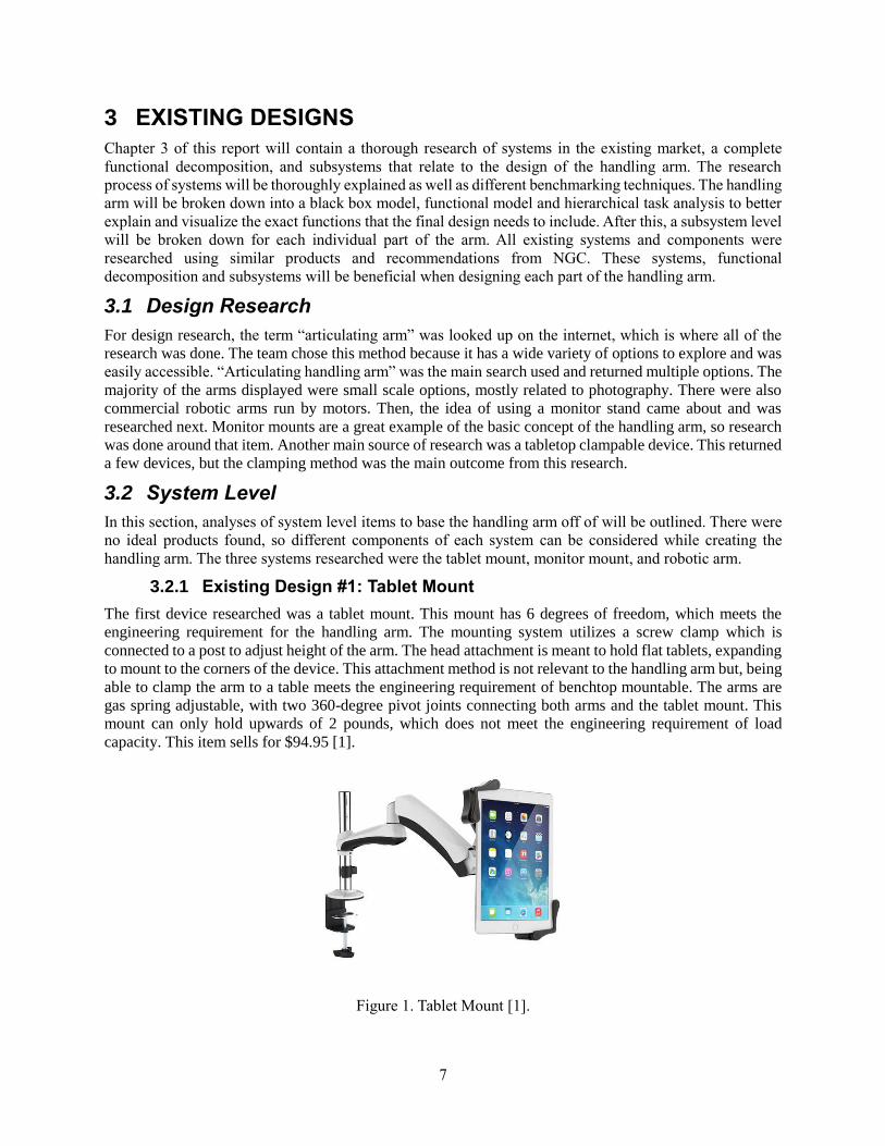
3.2.1 Existing Design #1: Tablet Mount
The first device researched was a tablet mount. This mount has 6 degrees of freedom, which meets the
engineering requirement for the handling arm. The mounting system utilizes a screw clamp which is
connected to a post to adjust height of the arm. The head attachment is meant to hold flat tablets, expanding
to mount to the corners of the device. This attachment method is not relevant to the handling arm but, being
able to clamp the arm to a table meets the engineering requirement of benchtop mountable. The arms are
gas spring adjustable, with two 360-degree pivot joints connecting both arms and the tablet mount. This
mount can only hold upwards of 2 pounds, which does not meet the engineering requirement of load
capacity. This item sells for $94.95 [1].
Figure 1. Tablet Mount [1].

8
3.2.2 Existing Design #2: Computer Monitor Mount
The second item researched was a monitor mount. This arm system was table-top mountable and moved in
6 degrees of freedom, as needed from the engineering requirements. The arms utilize gas springs, making
for easy manipulation of the monitor, which is another engineering requirement. The mount has bolt a
pattern VESA for 100 x 100 millimeters or 75 x 75 millimeters for monitors, which could be adapted for
different mounting patterns for avionics. The joint at the base and monitor can rotate ±90 degrees while the
middle joint can rotate 360 degrees, giving the needed 6 degrees of freedom. This device can hold up to 33
pounds, well over the maximum weight required for the handling arm. This mount is made of aircraft grade
aluminum which is strong and lightweight. This mount sells for $129.99 [2].
Figure 2. Monitor Mount [2].
3.2.3 Existing Design #3: Robotic Arm Kit
The next device researched was a 6 degrees of freedom robotic arm kit. This was benchmarked for the
geometry of the device. It is electric powered and not tabletop clampable, both of which do not meet the
handling arm’s engineering requirements. This robotic arm kit only met the 6 degrees of freedom
requirement but was used to look at the geometry of the joints. This is made of plastic, which will be too
weak for our weight requirement. This robotic arm sells for $299.00 [3].
Figure 3. Robotic Arm Kit [3].
9
3.3 Functional Decomposition
In this section, the functional decomposition of a universal articulating handling arm will be discussed. This
is done to gain a better understanding of the object’s function. In the functional decomposition, there will
be a discussion about the inputs and outputs required by the handling arm. The decomposition of the
handling arm will be broken down into multiple parts: a black box model, a functional model, and a
hierarchical task analysis. The black box model helps identify the main purpose of the handling arm while
the functional model breaks down each subsystem/component required and how the handling arm will
accomplish the main goal. The hierarchical task analysis gives a step by step procedure on how to properly
use the handling arm.
3.3.1 Black Box Model
The black box model helps to determine the main function with inputs and outputs for the handling arm.
By creating the black box model, the physical form and the function of the handling arm can be separated.
This helps in the concept generation because it allows the team to focus on meeting the functionality of the
handling arm while not being restricted by what a typical handling arm looks like.
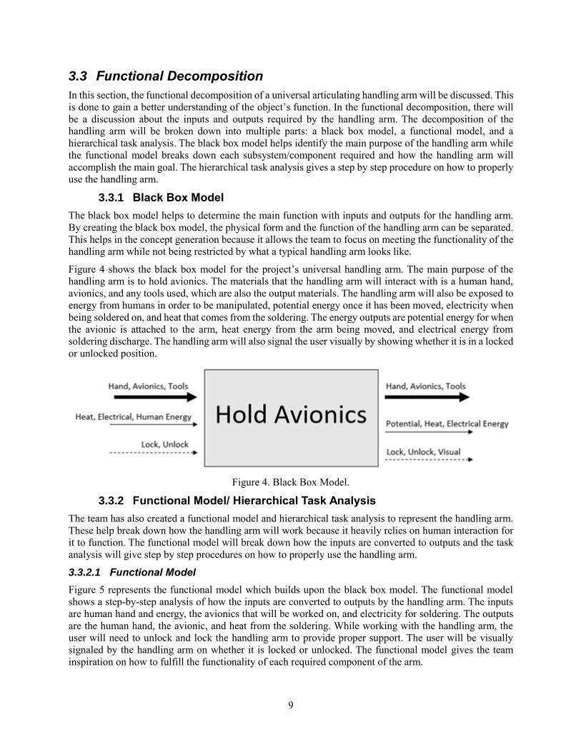
Figure 4 shows the black box model for the project’s universal handling arm. The main purpose of the
handling arm is to hold avionics. The materials that the handling arm will interact with is a human hand,
avionics, and any tools used, which are also the output materials. The handling arm will also be exposed to
energy from humans in order to be manipulated, potential energy once it has been moved, electricity when
being soldered on, and heat that comes from the soldering. The energy outputs are potential energy for when
the avionic is attached to the arm, heat energy from the arm being moved, and electrical energy from
soldering discharge. The handling arm will also signal the user visually by showing whether it is in a locked
or unlocked position.
Figure 4. Black Box Model.
3.3.2 Functional Model/ Hierarchical Task Analysis
The team has also created a functional model and hierarchical task analysis to represent the handling arm.
These help break down how the handling arm will work because it heavily relies on human interaction for
it to function. The functional model will break down how the inputs are converted to outputs and the task
analysis will give step by step procedures on how to properly use the handling arm.
3.3.2.1 Functional Model
Figure 5 represents the functional model which builds upon the black box model. The functional model
shows a step-by-step analysis of how the inputs are converted to outputs by the handling arm. The inputs
are human hand and energy, the avionics that will be worked on, and electricity for soldering. The outputs
are the human hand, the avionic, and heat from the soldering. While working with the handling arm, the
user will need to unlock and lock the handling arm to provide proper support. The user will be visually
signaled by the handling arm on whether it is locked or unlocked. The functional model gives the team
inspiration on how to fulfill the functionality of each required component of the arm.
10
Figure 5. Functional Model.
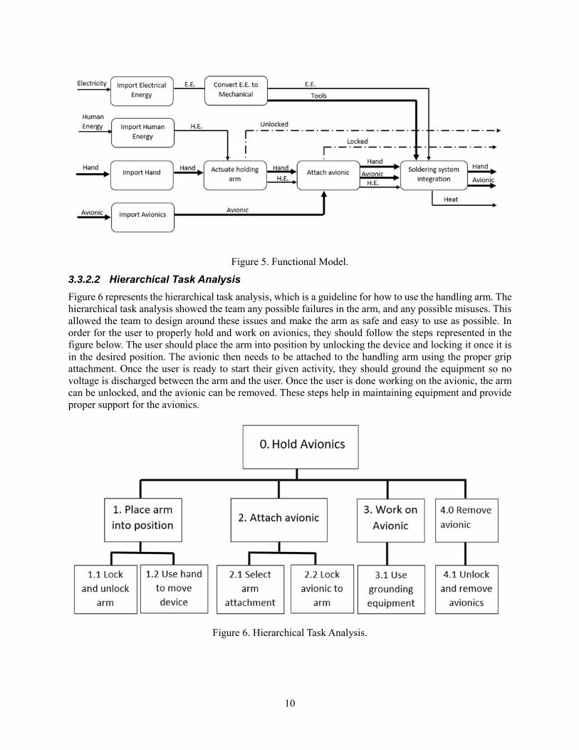
3.3.2.2 Hierarchical Task Analysis
Figure 6 represents the hierarchical task analysis, which is a guideline for how to use the handling arm. The
hierarchical task analysis showed the team any possible failures in the arm, and any possible misuses. This
allowed the team to design around these issues and make the arm as safe and easy to use as possible. In
order for the user to properly hold and work on avionics, they should follow the steps represented in the
figure below. The user should place the arm into position by unlocking the device and locking it once it is
in the desired position. The avionic then needs to be attached to the handling arm using the proper grip
attachment. Once the user is ready to start their given activity, they should ground the equipment so no
voltage is discharged between the arm and the user. Once the user is done working on the avionic, the arm
can be unlocked, and the avionic can be removed. These steps help in maintaining equipment and provide
proper support for the avionics.
Figure 6. Hierarchical Task Analysis.
11
3.4 Subsystem Level
To look more in depth at the future design of the handling arm, it is important to break it down into multiple
parts and research each thoroughly. Based on the engineering requirements, the handling arm was broken
into four parts: table attachments, mechanical joints, head attachments and locking mechanisms. Each of
these parts were be broken down into three existing designs that pertain to the corresponding topic. Once
simplified, each of the subsystems can be used in the design of the handling arm.
3.4.1 Subsystem #1: Table Attachments
One of the given customer requirements for the arm was that it has to be benchtop mountable. To attain
this, a table attachment is needed to secure the arm to the benchtop. The following three different clamp
systems were researched and analyzed: c-clamp, spring clamp and hand screw clamp. Any of these
subsystems can be used in the design for the arm.
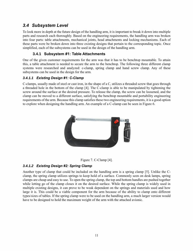
3.4.1.1 Existing Design #1: C-Clamp
C-clamps, usually made of steel or cast iron, in the shape of a C, utilizes a threaded screw that goes through
a threaded hole in the bottom of the clamp [4]. The C-clamp is able to be manipulated by tightening the
screw around the surface at the desired pressure. To release the clamp, the screw can be loosened, and the
clamp can be moved to a different surface, satisfying the benchtop mountable and portability engineering
requirements of the arm. Because this clamp satisfies these two engineering requirements, it is a good option
to explore when designing the handling arm. An example of a C-clamp can be seen in Figure 6.
Figure 7. C-Clamp [4].
3.4.1.2 Existing Design #2: Spring Clamp
Another type of clamp that could be included on the handling arm is a spring clamp [5]. Unlike the C-
clamp, the spring clamp utilizes springs to keep hold of a surface. Commonly seen on desk lamps, spring
clamps are cheap and easy to use. To open the spring clamp, the top and bottom handles are pushed together
while letting go of the clamp closes it on the desired surface. While the spring clamp is widely used in
multiple existing designs, it can prove to be weak dependent on the springs and materials used and how
large it is. This could be a viable component for the arm because of the ability to clamp onto different
types/sizes of tables. If the spring clamp were to be used on the handling arm, a much larger version would
have to be designed to hold the maximum weight of the arm with the attached avionic.

12
Figure 8. Spring Clamp [5].
3.4.1.3 Existing Design #3: Hand Screw Clamp
A hand screw clamp (Figure 9), usually made of wood, utilizes two screws on each side to close the clamp
around the desired object [6]. Because it is made out of wood, it is weaker than a C-clamp or a spring clamp.
It also is difficult to maneuver since there are two screws to tighten on either side instead of one. It is
important that the user be able to clamp the arm on the desired benchtop with as much ease as possible, so
this type of clamp could be feasible for the arm but would require many modifications.
Figure 9. Hand Screw Clamp [6].
3.4.2 Subsystem #2: Mechanical Joints
In order to provide a handling arm that meets the client’s expectations and needs, it must have six degrees
of freedom. To accomplish this, the right joints must be selected and analyzed to provide sufficient degrees
of freedom. These joints would pertain to the overall human interaction with the arm since they are
responsible for maneuverability.
3.4.2.1 Existing Design #1: Universal Joints
Universal joints, which can be seen in Figure 10, allow for two shafts to connect and transmit torque [7].
The joint allows for axial rotation and bending which will add to the degrees of freedom of the system.
Universal joints are also relatively cheap and easy to obtain. The main disadvantage is that the joint is prone
to wear if not properly lubricated and maintained. The universal joint can be easily applied to the handling
arm to help with the ease of manipulation requirements because they rotate easily and have a full range of
motion.
13
Figure 10. Universal Joints [7].
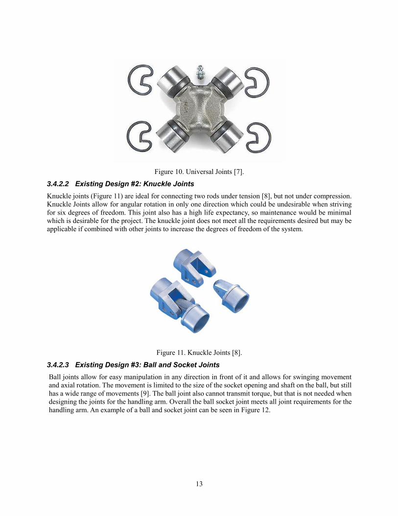
3.4.2.2 Existing Design #2: Knuckle Joints
Knuckle joints (Figure 11) are ideal for connecting two rods under tension [8], but not under compression.
Knuckle Joints allow for angular rotation in only one direction which could be undesirable when striving
for six degrees of freedom. This joint also has a high life expectancy, so maintenance would be minimal
which is desirable for the project. The knuckle joint does not meet all the requirements desired but may be
applicable if combined with other joints to increase the degrees of freedom of the system.
Figure 11. Knuckle Joints [8].
3.4.2.3 Existing Design #3: Ball and Socket Joints
Ball joints allow for easy manipulation in any direction in front of it and allows for swinging movement
and axial rotation. The movement is limited to the size of the socket opening and shaft on the ball, but still
has a wide range of movements [9]. The ball joint also cannot transmit torque, but that is not needed when
designing the joints for the handling arm. Overall the ball socket joint meets all joint requirements for the
handling arm. An example of a ball and socket joint can be seen in Figure 12.
14
Figure 12. Ball and Socket Joint [9].
3.4.3 Subsystem #3: Head Attachments
One of the features that the customer desires is different types of head attachments to put on the end of the
handling arm. This is to ensure that anything that NGC needs to be held on the arm has some type of
attachment that can secure it to the arm.
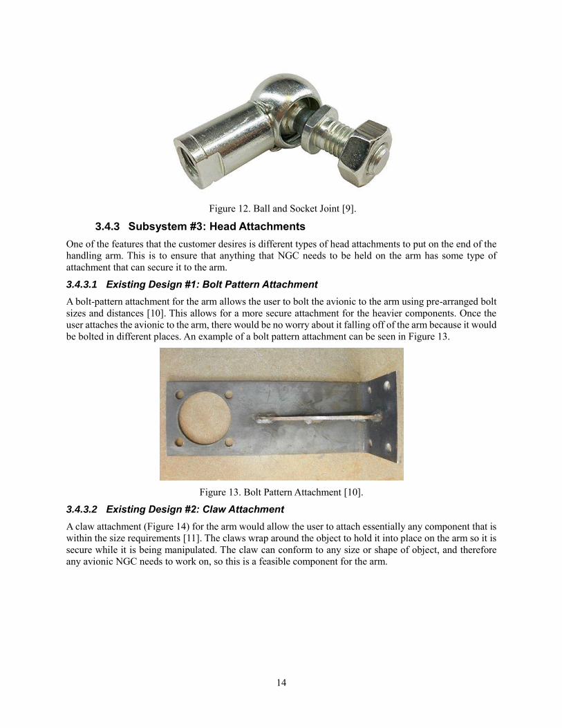
3.4.3.1 Existing Design #1: Bolt Pattern Attachment
A bolt-pattern attachment for the arm allows the user to bolt the avionic to the arm using pre-arranged bolt
sizes and distances [10]. This allows for a more secure attachment for the heavier components. Once the
user attaches the avionic to the arm, there would be no worry about it falling off of the arm because it would
be bolted in different places. An example of a bolt pattern attachment can be seen in Figure 13.
Figure 13. Bolt Pattern Attachment [10].
3.4.3.2 Existing Design #2: Claw Attachment
A claw attachment (Figure 14) for the arm would allow the user to attach essentially any component that is
within the size requirements [11]. The claws wrap around the object to hold it into place on the arm so it is
secure while it is being manipulated. The claw can conform to any size or shape of object, and therefore
any avionic NGC needs to work on, so this is a feasible component for the arm.

15
Figure 14. Claw Attachment [11].
3.4.3.3 Existing Design #3: Clamp Attachment
A clamp attachment (Figure 15) for the arm would have two clamps that would clamp down on the
component on the arm to be worked on [12]. The two clamps would be able to be tightened and loosened
to accommodate for different sizes of avionics. This design would be optimal for square parts but can work
with many shapes. This component could be useful for the arm is the avionic is within the size capability
of the claw attachments.
Figure 15. Clamp Attachment [12].
3.4.4 Subsystem #4: Locking Mechanism
The subsystem for locking mechanisms is based on the locking of joints. Ideally, the team wants all the
joints to lock with one knob or switch, so the main focus will be on that. Having all of the joints lock out is
important for when the arm is setup for the user, so it can handle more weight and be more rugged for the
user to manipulate and work on the avionic.
3.4.4.1 Existing Design #1: Titan Support Arm
The Titan Support Arm (Figure 16) can lock out joints with one screw on the middle joint [13]. This arm
has 3 joints with a center joint using a knob that changes the force it takes to move the joints. This system
works based on the pressure put on each joint when the knob is tightened. The team plans to order one of
these arms to test and reverse engineer to see if it can be scaled into the size needed for our arm.
16
Figure 16. Titan Support Arm [13].
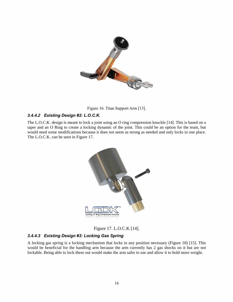
3.4.4.2 Existing Design #2: L.O.C.K.
The L.O.C.K. design is meant to lock a joint using an O ring compression knuckle [14]. This is based on a
taper and an O Ring to create a locking dynamic of the joint. This could be an option for the team, but
would need some modifications because it does not seem as strong as needed and only locks in one place.
The L.O.C.K. can be seen in Figure 17.
Figure 17. L.O.C.K [14].
3.4.4.3 Existing Design #3: Locking Gas Spring
A locking gas spring is a locking mechanism that locks in any position necessary (Figure 18) [15]. This
would be beneficial for the handling arm because the arm currently has 2 gas shocks on it but are not
lockable. Being able to lock these out would make the arm safer to use and allow it to hold more weight.

17
Figure 18. Locking Gas Spring [15].

18
4 DESIGNS CONSIDERED
This section showcases the team’s top five designs as decided by the Pugh Chart (Figure 24, 25). The next
five highest-ranked designs are included in Appendix B. Each design has a specific title, descriptions of the
notable features, a hand-drawn sketch of the concept, and an advantage and disadvantage list that focus on
the customer and engineering requirements. The following designs are not discussed in order of their scores
but are grouped as the top five in the following sections with the following five designs located in Appendix
B.
4.1 Design #1: Bio-Inspired Leg Springs
One of the top designs that the team considered was a concept developed from bush babies in nature. These
animals store energy in their legs so that when it comes time, they are able to jump 20-30 times their own
height. This ability to store energy and maintain normal functions was the basis for this idea using zero-
link springs [16].
As seen in Figure 19, this design features a C-clamp at the base to secure the arm to the benchtop. It also
has two joints as opposed to three, similar to the leg shape of a bush baby. The zero-link springs are capable
of holding the attached device up, without it falling. The springs will also allow for easy maneuverability,
and the ability to lock out at a desired location. The head for this is a ball-joint that would allow for different
attachments to be added on. An advantage and disadvantage list for this design is shown in Table 2 below.
Figure 19. Bio-Inspired Leg Springs.
Table 2. Advantages and Disadvantages for Bio-Inspired Leg Springs.
Advantages Disadvantages
Ease of manipulation May not hold up to 43.75lbs without falling at unlocked
position
Two joints have less places to fail Limited vertical adjustment
C-Clamp sufficiently secures arm to
table
Unable to have all six degrees of freedom
Easy to ground for ESD compliance
Not many parts so lower cost
C-
clamp
Spring
Arm
19
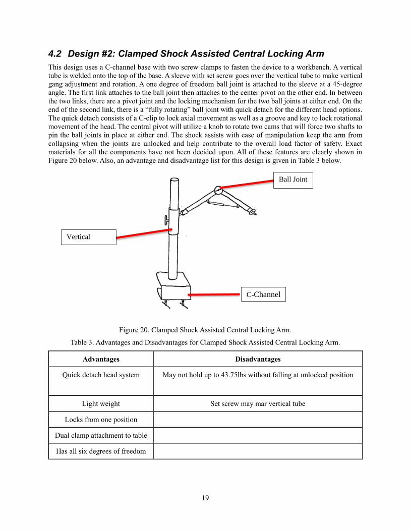
4.2 Design #2: Clamped Shock Assisted Central Locking Arm
This design uses a C-channel base with two screw clamps to fasten the device to a workbench. A vertical
tube is welded onto the top of the base. A sleeve with set screw goes over the vertical tube to make vertical
gang adjustment and rotation. A one degree of freedom ball joint is attached to the sleeve at a 45-degree
angle. The first link attaches to the ball joint then attaches to the center pivot on the other end. In between
the two links, there are a pivot joint and the locking mechanism for the two ball joints at either end. On the
end of the second link, there is a “fully rotating” ball joint with quick detach for the different head options.
The quick detach consists of a C-clip to lock axial movement as well as a groove and key to lock rotational
movement of the head. The central pivot will utilize a knob to rotate two cams that will force two shafts to
pin the ball joints in place at either end. The shock assists with ease of manipulation keep the arm from
collapsing when the joints are unlocked and help contribute to the overall load factor of safety. Exact
materials for all the components have not been decided upon. All of these features are clearly shown in
Figure 20 below. Also, an advantage and disadvantage list for this design is given in Table 3 below.
Figure 20. Clamped Shock Assisted Central Locking Arm.
Table 3. Advantages and Disadvantages for Clamped Shock Assisted Central Locking Arm.
Advantages Disadvantages
Quick detach head system May not hold up to 43.75lbs without falling at unlocked position
Light weight Set screw may mar vertical tube
Locks from one position
Dual clamp attachment to table
Has all six degrees of freedom
Ball Joint
C-Channel
Vertical
Sleeve
20
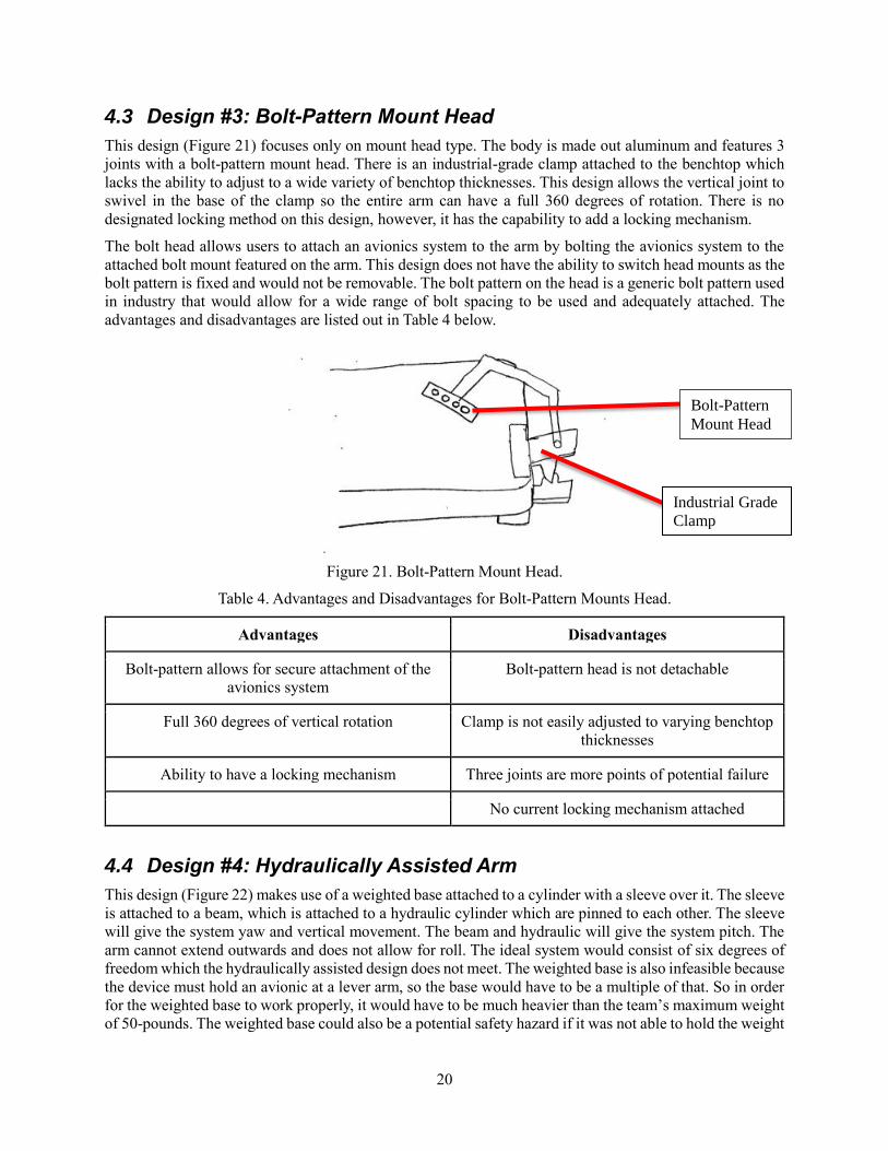
4.3 Design #3: Bolt-Pattern Mount Head
This design (Figure 21) focuses only on mount head type. The body is made out aluminum and features 3
joints with a bolt-pattern mount head. There is an industrial-grade clamp attached to the benchtop which
lacks the ability to adjust to a wide variety of benchtop thicknesses. This design allows the vertical joint to
swivel in the base of the clamp so the entire arm can have a full 360 degrees of rotation. There is no
designated locking method on this design, however, it has the capability to add a locking mechanism.
The bolt head allows users to attach an avionics system to the arm by bolting the avionics system to the
attached bolt mount featured on the arm. This design does not have the ability to switch head mounts as the
bolt pattern is fixed and would not be removable. The bolt pattern on the head is a generic bolt pattern used
in industry that would allow for a wide range of bolt spacing to be used and adequately attached. The
advantages and disadvantages are listed out in Table 4 below.
Figure 21. Bolt-Pattern Mount Head.
Table 4. Advantages and Disadvantages for Bolt-Pattern Mounts Head.
Advantages Disadvantages
Bolt-pattern allows for secure attachment of the
avionics system
Bolt-pattern head is not detachable
Full 360 degrees of vertical rotation Clamp is not easily adjusted to varying benchtop
thicknesses
Ability to have a locking mechanism Three joints are more points of potential failure
No current locking mechanism attached
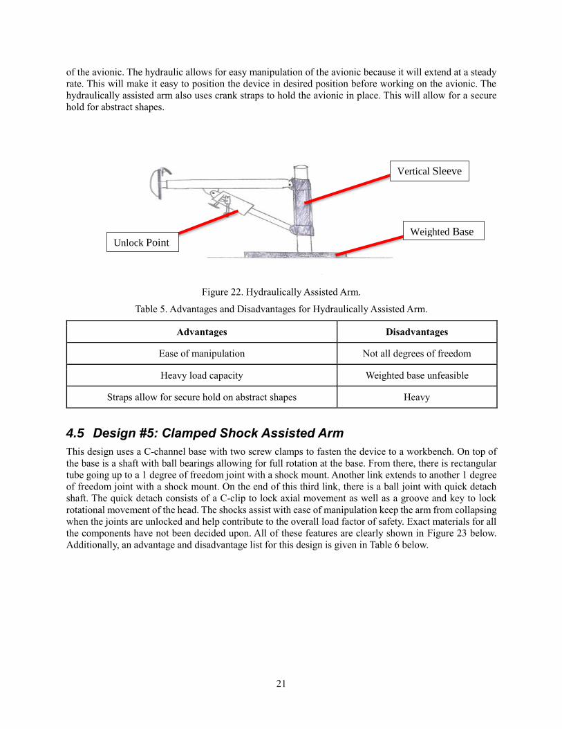
4.4 Design #4: Hydraulically Assisted Arm
This design (Figure 22) makes use of a weighted base attached to a cylinder with a sleeve over it. The sleeve
is attached to a beam, which is attached to a hydraulic cylinder which are pinned to each other. The sleeve
will give the system yaw and vertical movement. The beam and hydraulic will give the system pitch. The
arm cannot extend outwards and does not allow for roll. The ideal system would consist of six degrees of
freedom which the hydraulically assisted design does not meet. The weighted base is also infeasible because
the device must hold an avionic at a lever arm, so the base would have to be a multiple of that. So in order
for the weighted base to work properly, it would have to be much heavier than the team’s maximum weight
of 50-pounds. The weighted base could also be a potential safety hazard if it was not able to hold the weight
Bolt-Pattern
Mount Head
Industrial Grade
Clamp
21
of the avionic. The hydraulic allows for easy manipulation of the avionic because it will extend at a steady
rate. This will make it easy to position the device in desired position before working on the avionic. The
hydraulically assisted arm also uses crank straps to hold the avionic in place. This will allow for a secure
hold for abstract shapes.
Figure 22. Hydraulically Assisted Arm.
Table 5. Advantages and Disadvantages for Hydraulically Assisted Arm.
Advantages Disadvantages
Ease of manipulation Not all degrees of freedom
Heavy load capacity Weighted base unfeasible
Straps allow for secure hold on abstract shapes Heavy
4.5 Design #5: Clamped Shock Assisted Arm
This design uses a C-channel base with two screw clamps to fasten the device to a workbench. On top of
the base is a shaft with ball bearings allowing for full rotation at the base. From there, there is rectangular
tube going up to a 1 degree of freedom joint with a shock mount. Another link extends to another 1 degree
of freedom joint with a shock mount. On the end of this third link, there is a ball joint with quick detach
shaft. The quick detach consists of a C-clip to lock axial movement as well as a groove and key to lock
rotational movement of the head. The shocks assist with ease of manipulation keep the arm from collapsing
when the joints are unlocked and help contribute to the overall load factor of safety. Exact materials for all
the components have not been decided upon. All of these features are clearly shown in Figure 23 below.
Additionally, an advantage and disadvantage list for this design is given in Table 6 below.
Weighted Base
Vertical Sleeve
Unlock Point

22
Figure 23. Clamped Shock Assisted Arm.
Table 6. Advantages and Disadvantages for Clamped Shock Assisted Arm.
Advantages Disadvantages
Ease of Manipulation No current locking mechanism attached
Has all six degrees of freedom Three joints are more points of potential failure
Dual clamp attachment to table
Quick detach head system
C-Channel
Pivot Joint
Pivot Joint
Pivot Joint
23
5 DESIGN SELECTED – First Semester
Chapter 5 will contain a thorough explanation of the design selected and how it was selected using a Pugh
chart and decision matrix. The rationale for the selection will be presented as well as an in-depth description
of the design as a whole and the individual subsystems: table attachment, mechanical joints, head
attachments, and locking mechanisms. Modifications to the final design will also be explained.
5.1 Rationale for Design Selection
The final design, selected using a Pugh chart and decision matrix, is a combination of the Clamped Shock
Assisted Central Locking Arm and Hydraulically Assisted Arm designs described in Chapter 4. These two
designs ranked the highest when analyzed in the decision matrix.
5.1.1 Pugh Chart
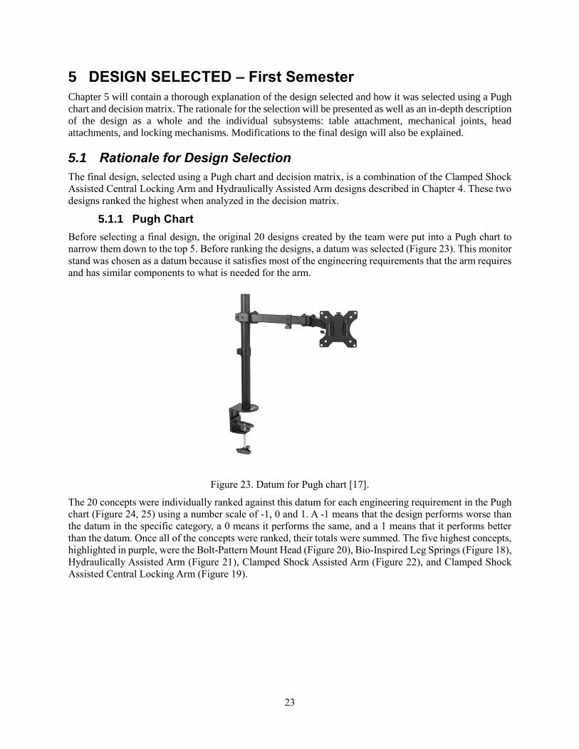
Before selecting a final design, the original 20 designs created by the team were put into a Pugh chart to
narrow them down to the top 5. Before ranking the designs, a datum was selected (Figure 23). This monitor
stand was chosen as a datum because it satisfies most of the engineering requirements that the arm requires
and has similar components to what is needed for the arm.
Figure 23. Datum for Pugh chart [17].
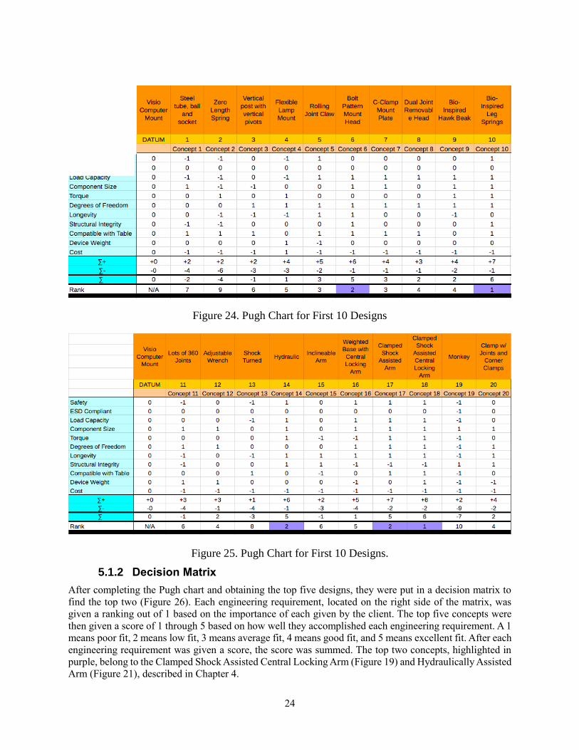
The 20 concepts were individually ranked against this datum for each engineering requirement in the Pugh
chart (Figure 24, 25) using a number scale of -1, 0 and 1. A -1 means that the design performs worse than
the datum in the specific category, a 0 means it performs the same, and a 1 means that it performs better
than the datum. Once all of the concepts were ranked, their totals were summed. The five highest concepts,
highlighted in purple, were the Bolt-Pattern Mount Head (Figure 20), Bio-Inspired Leg Springs (Figure 18),
Hydraulically Assisted Arm (Figure 21), Clamped Shock Assisted Arm (Figure 22), and Clamped Shock
Assisted Central Locking Arm (Figure 19).
24
Figure 24. Pugh Chart for First 10 Designs
Figure 25. Pugh Chart for First 10 Designs.
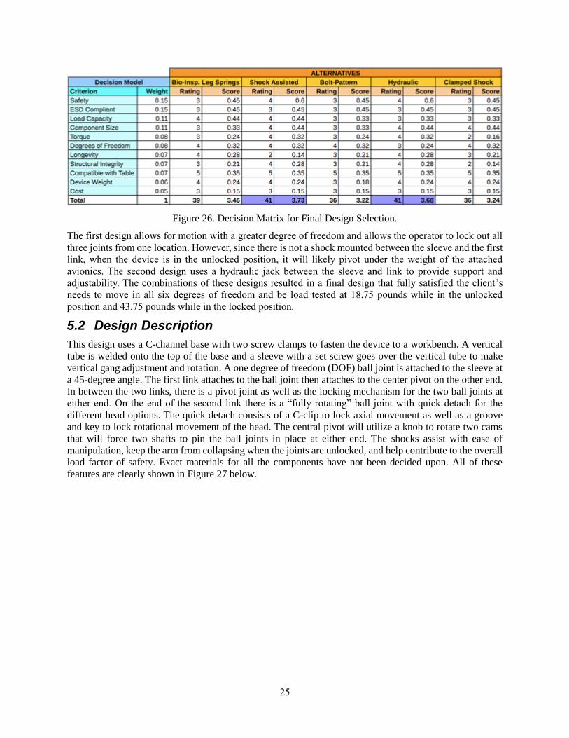
5.1.2 Decision Matrix
After completing the Pugh chart and obtaining the top five designs, they were put in a decision matrix to
find the top two (Figure 26). Each engineering requirement, located on the right side of the matrix, was
given a ranking out of 1 based on the importance of each given by the client. The top five concepts were
then given a score of 1 through 5 based on how well they accomplished each engineering requirement. A 1
means poor fit, 2 means low fit, 3 means average fit, 4 means good fit, and 5 means excellent fit. After each
engineering requirement was given a score, the score was summed. The top two concepts, highlighted in
purple, belong to the Clamped Shock Assisted Central Locking Arm (Figure 19) and Hydraulically Assisted
Arm (Figure 21), described in Chapter 4.
25
Figure 26. Decision Matrix for Final Design Selection.
The first design allows for motion with a greater degree of freedom and allows the operator to lock out all
three joints from one location. However, since there is not a shock mounted between the sleeve and the first
link, when the device is in the unlocked position, it will likely pivot under the weight of the attached
avionics. The second design uses a hydraulic jack between the sleeve and link to provide support and
adjustability. The combinations of these designs resulted in a final design that fully satisfied the client’s
needs to move in all six degrees of freedom and be load tested at 18.75 pounds while in the unlocked
position and 43.75 pounds while in the locked position.
5.2 Design Description
This design uses a C-channel base with two screw clamps to fasten the device to a workbench. A vertical
tube is welded onto the top of the base and a sleeve with a set screw goes over the vertical tube to make
vertical gang adjustment and rotation. A one degree of freedom (DOF) ball joint is attached to the sleeve at
a 45-degree angle. The first link attaches to the ball joint then attaches to the center pivot on the other end.
In between the two links, there is a pivot joint as well as the locking mechanism for the two ball joints at
either end. On the end of the second link there is a “fully rotating” ball joint with quick detach for the
different head options. The quick detach consists of a C-clip to lock axial movement as well as a groove
and key to lock rotational movement of the head. The central pivot will utilize a knob to rotate two cams
that will force two shafts to pin the ball joints in place at either end. The shocks assist with ease of
manipulation, keep the arm from collapsing when the joints are unlocked, and help contribute to the overall
load factor of safety. Exact materials for all the components have not been decided upon. All of these
features are clearly shown in Figure 27 below.

26
Figure 27. Final Design.
5.3 Design Subsystems
The final design consists of 4 different subsystems: table attachment, mechanical joints, head attachments
and locking mechanism. In this section, each subsystem will be explained and a sketch of each will be
presented.
5.3.1 Table Attachment
The final design utilizes an 8 x 6 x 5 inch channel with two ½ inch screw clamps to securely fasten it to the
workbench (Figure 28). These screw clamps will have 2 x 4 inch rectangular plates to increase surface area
and decrease the stress on the table. After consulting with a senior fabricator, it was learned that channel
does not come in these sizes, however the desired shape may be obtained by cutting off one side of
rectangular tubing.
Figure 28. C-Clamp for Final Design.
27
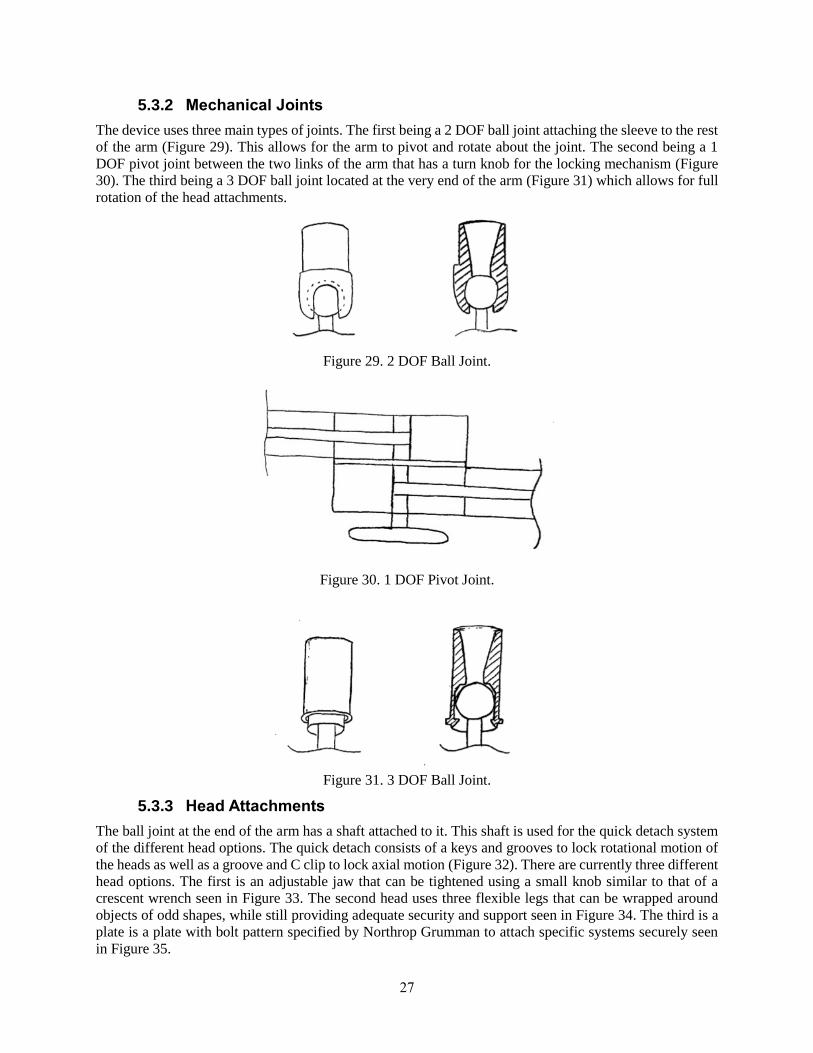
5.3.2 Mechanical Joints
The device uses three main types of joints. The first being a 2 DOF ball joint attaching the sleeve to the rest
of the arm (Figure 29). This allows for the arm to pivot and rotate about the joint. The second being a 1
DOF pivot joint between the two links of the arm that has a turn knob for the locking mechanism (Figure
30). The third being a 3 DOF ball joint located at the very end of the arm (Figure 31) which allows for full
rotation of the head attachments.
Figure 29. 2 DOF Ball Joint.
Figure 30. 1 DOF Pivot Joint.
Figure 31. 3 DOF Ball Joint.
5.3.3 Head Attachments
The ball joint at the end of the arm has a shaft attached to it. This shaft is used for the quick detach system
of the different head options. The quick detach consists of a keys and grooves to lock rotational motion of
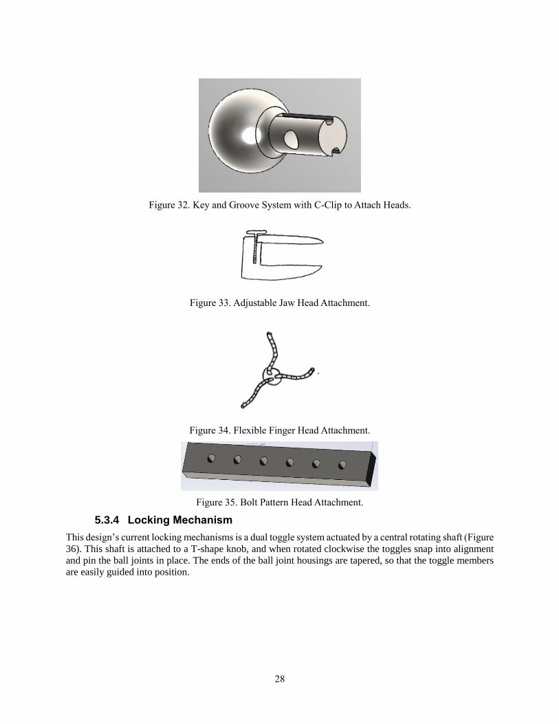
the heads as well as a groove and C clip to lock axial motion (Figure 32). There are currently three different
head options. The first is an adjustable jaw that can be tightened using a small knob similar to that of a
crescent wrench seen in Figure 33. The second head uses three flexible legs that can be wrapped around
objects of odd shapes, while still providing adequate security and support seen in Figure 34. The third is a
plate is a plate with bolt pattern specified by Northrop Grumman to attach specific systems securely seen
in Figure 35.
28
Figure 32. Key and Groove System with C-Clip to Attach Heads.
Figure 33. Adjustable Jaw Head Attachment.
Figure 34. Flexible Finger Head Attachment.
Figure 35. Bolt Pattern Head Attachment.
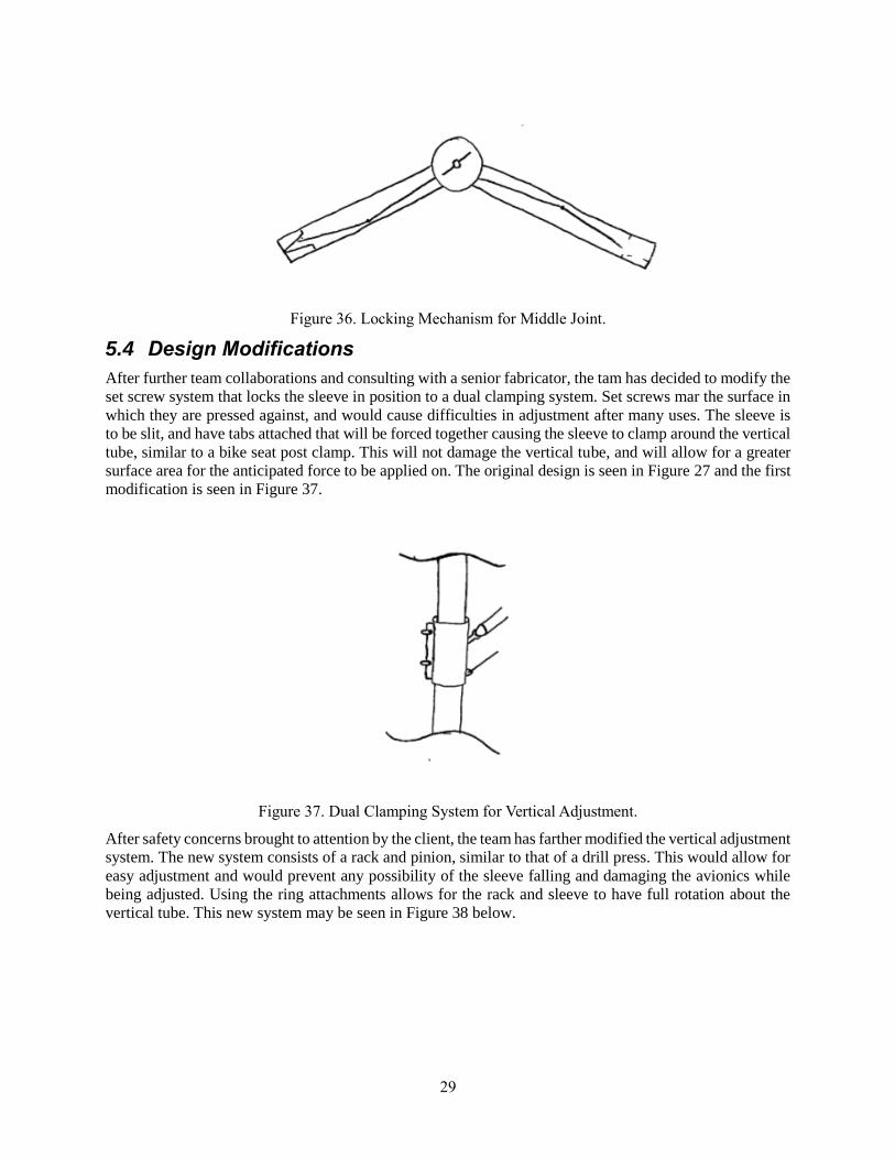
5.3.4 Locking Mechanism
This design’s current locking mechanisms is a dual toggle system actuated by a central rotating shaft (Figure
36). This shaft is attached to a T-shape knob, and when rotated clockwise the toggles snap into alignment
and pin the ball joints in place. The ends of the ball joint housings are tapered, so that the toggle members
are easily guided into position.
29
Figure 36. Locking Mechanism for Middle Joint.
5.4 Design Modifications
After further team collaborations and consulting with a senior fabricator, the tam has decided to modify the
set screw system that locks the sleeve in position to a dual clamping system. Set screws mar the surface in
which they are pressed against, and would cause difficulties in adjustment after many uses. The sleeve is
to be slit, and have tabs attached that will be forced together causing the sleeve to clamp around the vertical
tube, similar to a bike seat post clamp. This will not damage the vertical tube, and will allow for a greater
surface area for the anticipated force to be applied on. The original design is seen in Figure 27 and the first
modification is seen in Figure 37.
Figure 37. Dual Clamping System for Vertical Adjustment.
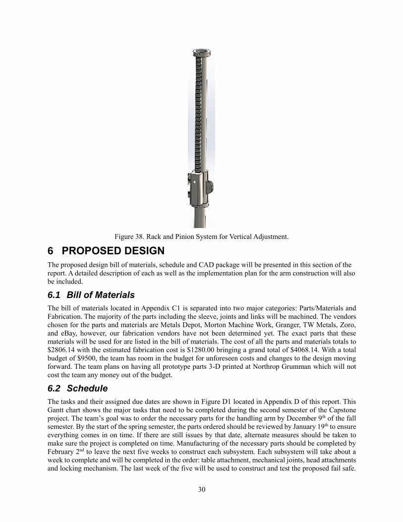
After safety concerns brought to attention by the client, the team has farther modified the vertical adjustment
system. The new system consists of a rack and pinion, similar to that of a drill press. This would allow for
easy adjustment and would prevent any possibility of the sleeve falling and damaging the avionics while
being adjusted. Using the ring attachments allows for the rack and sleeve to have full rotation about the
vertical tube. This new system may be seen in Figure 38 below.
30
Figure 38. Rack and Pinion System for Vertical Adjustment.
6 PROPOSED DESIGN
The proposed design bill of materials, schedule and CAD package will be presented in this section of the
report. A detailed description of each as well as the implementation plan for the arm construction will also
be included.
6.1 Bill of Materials
The bill of materials located in Appendix C1 is separated into two major categories: Parts/Materials and
Fabrication. The majority of the parts including the sleeve, joints and links will be machined. The vendors
chosen for the parts and materials are Metals Depot, Morton Machine Work, Granger, TW Metals, Zoro,
and eBay, however, our fabrication vendors have not been determined yet. The exact parts that these
materials will be used for are listed in the bill of materials. The cost of all the parts and materials totals to
$2806.14 with the estimated fabrication cost is $1280.00 bringing a grand total of $4068.14. With a total
budget of $9500, the team has room in the budget for unforeseen costs and changes to the design moving
forward. The team plans on having all prototype parts 3-D printed at Northrop Grumman which will not
cost the team any money out of the budget.
6.2 Schedule
The tasks and their assigned due dates are shown in Figure D1 located in Appendix D of this report. This
Gantt chart shows the major tasks that need to be completed during the second semester of the Capstone
project. The team’s goal was to order the necessary parts for the handling arm by December 9th of the fall
semester. By the start of the spring semester, the parts ordered should be reviewed by January 19th to ensure
everything comes in on time. If there are still issues by that date, alternate measures should be taken to
make sure the project is completed on time. Manufacturing of the necessary parts should be completed by
February 2nd to leave the next five weeks to construct each subsystem. Each subsystem will take about a
week to complete and will be completed in the order: table attachment, mechanical joints, head attachments
and locking mechanism. The last week of the five will be used to construct and test the proposed fail safe.
31
After the subsystem and fail safe constructions are completed, the unit assembly will be completed by
March 29th. The remaining weeks will be dedicated to testing and presenting the final project; complete
with a presentation poster, operations manual, CAD package and final report all to be completed by May
8th.
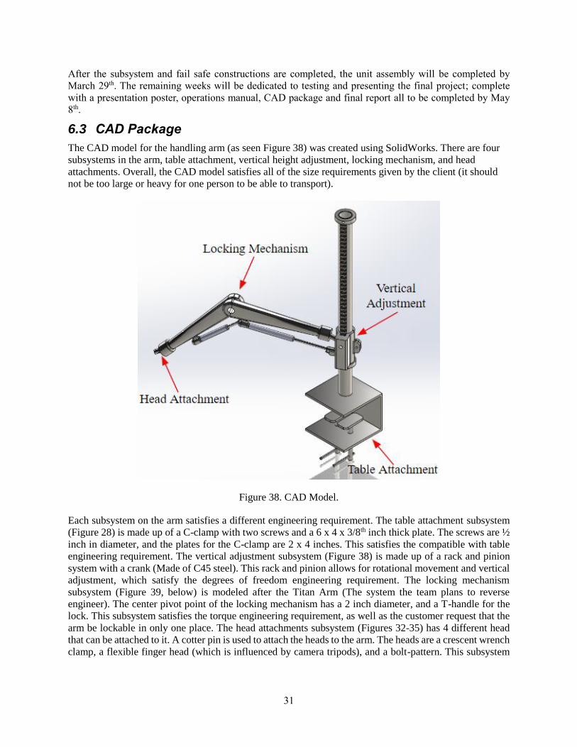
6.3 CAD Package
The CAD model for the handling arm (as seen Figure 38) was created using SolidWorks. There are four
subsystems in the arm, table attachment, vertical height adjustment, locking mechanism, and head
attachments. Overall, the CAD model satisfies all of the size requirements given by the client (it should
not be too large or heavy for one person to be able to transport).
Figure 38. CAD Model.
Each subsystem on the arm satisfies a different engineering requirement. The table attachment subsystem
(Figure 28) is made up of a C-clamp with two screws and a 6 x 4 x 3/8th inch thick plate. The screws are ½
inch in diameter, and the plates for the C-clamp are 2 x 4 inches. This satisfies the compatible with table
engineering requirement. The vertical adjustment subsystem (Figure 38) is made up of a rack and pinion
system with a crank (Made of C45 steel). This rack and pinion allows for rotational movement and vertical
adjustment, which satisfy the degrees of freedom engineering requirement. The locking mechanism
subsystem (Figure 39, below) is modeled after the Titan Arm (The system the team plans to reverse
engineer). The center pivot point of the locking mechanism has a 2 inch diameter, and a T-handle for the
lock. This subsystem satisfies the torque engineering requirement, as well as the customer request that the
arm be lockable in only one place. The head attachments subsystem (Figures 32-35) has 4 different head
that can be attached to it. A cotter pin is used to attach the heads to the arm. The heads are a crescent wrench
clamp, a flexible finger head (which is influenced by camera tripods), and a bolt-pattern. This subsystem
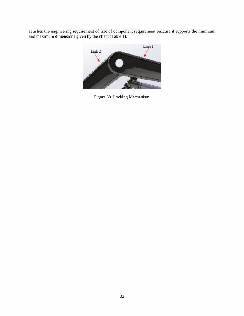
32
satisfies the engineering requirement of size of component requirement because it supports the minimum
and maximum dimensions given by the client (Table 1).
Figure 39. Locking Mechanism.
33
7 REFERENCES
[1] “CTA Digital Arm Mount,” Adorama. [Online]. Available:
https://www.adorama.com/ctapadhaam.html. [Accessed: 17-Sep-2018].
[2] “Loctek Monitor Mount Heavy Duty Gas Spring Swing Monitor Arm Desk Mount Stand Fits for 10’-
34’ Monitor Weighting 13.2-33 lbs - D7L,” Amazon. [Online]. Available:
https://www.amazon.com/Loctek-Monitor-Spring-Weighting-13-2-
33/dp/B01BXP9LT6/ref=sr_1_5?ie=UTF8&qid=1537070288&sr=8-5&keywords=clamp monitor mount.
[Accessed: 17-Sep-2018].
[3] Anon, (2018). [online] Available at: https://www.robotshop.com/en/6-dof-robot-arm-kit.html
[Accessed 17 Sep. 2018].
[4] "C-clamp - Clamps - Clamps & Vises - The Home Depot", thehomedepot.com, 2018. [Online].
Available: https://www.homedepot.com/p/Husky-6-in-Quick-Adjustable-C-Clamp-with-Rubber-Handle-
99683/302347522. [Accessed: 12- Oct- 2018].
[5] “4 in. Steel Spring Clamp with Handles and Tips", thehomedepot.com, 2018. [Online]. Available:
https://www.homedepot.com/p/BESSEY-4-in-Steel-Spring-Clamp-with-Handles-and-Tips-
XM10/205512961. [Accessed: 12- Oct- 2018].
[6] "12 in. Handscrew Clamp", harborfreight.com, 2018. [Online]. Available:
https://www.harborfreight.com/12-in-handscrew-clamp-60551.html. [Accessed: 12- Oct- 2018].
[7] “Advance Auto Parts - Down for Maintenance", Shop.advanceautoparts.com, 2018. [Online].
Available: https://shop.advanceautoparts.com/p/moog-driveline-products-universal-joint-354/10086740-
P?navigationPath=L1*14925%7CL2*15051%7CL3*16357. [Accessed: 12- Oct- 2018].
[8] Knuckle Joints", Doughty-engineering.co.uk, 2018. [Online]. Available: http://www.doughty-
engineering.co.uk/cgi-bin/trolleyed_public.cgi?action=showprod_T58730. [Accessed: 12- Oct- 2018].
[9] "J.W. Winco 5NXF1/B DIN71802 Ball Joint, 8 mm Diameter, M5 x 0.8 Tapped Right Hand Thread,
M5 x 0.8 Threaded Shank, 10 mm Thread Length with Safety Catch", Amazon.com, 2018. [Online].
Available: https://www.amazon.com/Winco-5NXF1-DIN71802-Diameter-
Threaded/dp/B018R9S40S/ref=lp_16411991_1_1?s=industrial&ie=UTF8&qid=1539951103&sr=1-1.
[Accessed: 12- Oct- 2018].
[10] “Universal Disc Harrow L-plate for Brearings | eBay", eBay.com, 2018. [Online]. Available:
https://www.ebay.com/p/Universal-Disc-Harrow-L-plate-for-
Brearings/1248432717?iid=181705966852&chn=ps. [Accessed: 12- Oct- 2018].
[11] "Flexible Lightweight Portable Tripod for Projector DSLR Cameras (Black&White)", Amazon.com,
2018. [Online]. Available: https://www.amazon.com/Flexible-Lightweight-Portable-Projector-
Cameras/dp/B00LXG9NN0/ref=asc_df_B00LXG9NN0/?tag=hyprod-
20&linkCode=df0&hvadid=167143377764&hvpos=1o2&hvnetw=g&hvrand=14411341506217609834&
hvpone=&hvptwo=&hvqmt=&hvdev=c&hvdvcmdl=&hvlocint=&hvlocphy=9060078&hvtargid=pla-
314119775882&psc=1. [Accessed: 12- Oct- 2018].
[12] "K&M 23800.500.55", Sweetwater.com, 2018. [Online]. Available:
https://www.sweetwater.com/store/detail/MicStdExtBrkS--k-and-m-
23800.500.55?mrkgcl=28&mrkgadid=3316426354&rkg_id=0&product_id=MicStdExtBrkS&campaignty
34
pe=shopping&campaign=aaShopping%20-%20SKU%20-
%20Studio%20%26%20Recording&adgroup=Microphones%20%26%20Wireless%20-
%20K%26M%20-
%20micstdextbrks&placement=google&adpos=1o1&creative=303058207356&device=c&matchtype=&n
etwork=g&gclid=CjwKCAjwgabeBRBuEiwACD4R5ibTLHKsM_DJ6yZRBFV-
NphaayV59DfevcCrpgI5C7tCcYiIrw5-pBoC12cQAvD_BwE. [Accessed: 12- Oct- 2018].
[13] “Titan Arm (Orange)", brighttangerine.com, 2018. [Online]. Available:
https://www.brighttangerine.com/store/titan-support-arm-orange/. [Accessed: 12- Oct- 2018].
[14] “Innovations and Patents : L.O.C.K.™ Knuckle System", Bklighting.com, 2018. [Online]. Available:
http://www.bklighting.com/products/innovations-and-patents/832-l-o-c-k-knuckle-system-
information.html. [Accessed: 12- Oct- 2018].
[15] “F. Gas Spring, "Gas Spring, Locking, Steel, Force 30", Grainger.com, 2018. [Online]. Available:
https://www.grainger.com/product/BANSBACH-EASYLIFT-Gas-Spring-6FRT9. [Accessed: 12- Oct-
2018].
[16] "Bush baby | primate", britannica.com, 2018. [Online]. Available:
https://www.britannica.com/animal/bush-baby. [Accessed: 12- Oct- 2018].
[17] “VIVO Full Motion Single VESA Computer Monitor Desk Mount Stand with Articulating Double
Center Arm Joint | for 13" to 32" Screens (STAND-V101)” Amazon.com, 2018. [Online]. Available:
https://www.amazon.com/VIVO-Computer-Monitor-Articulating-STAND-
V101/dp/B074G56JCQ/ref=asc_df_B074G56JCQ/?tag=hyprod-
20&linkCode=df0&hvadid=198057545906&hvpos=1o4&hvnetw=g&hvrand=12454044501909214180&
hvpone=&hvptwo=&hvqmt=&hvdev=c&hvdvcmdl=&hvlocint=&hvlocphy=1013406&hvtargid=pla-
543460906952&psc=1. [Accessed: 12- Oct- 2018].
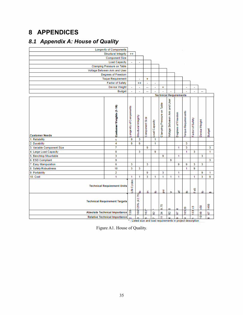
35
8 APPENDICES
8.1 Appendix A: House of Quality
Figure A1. House of Quality.
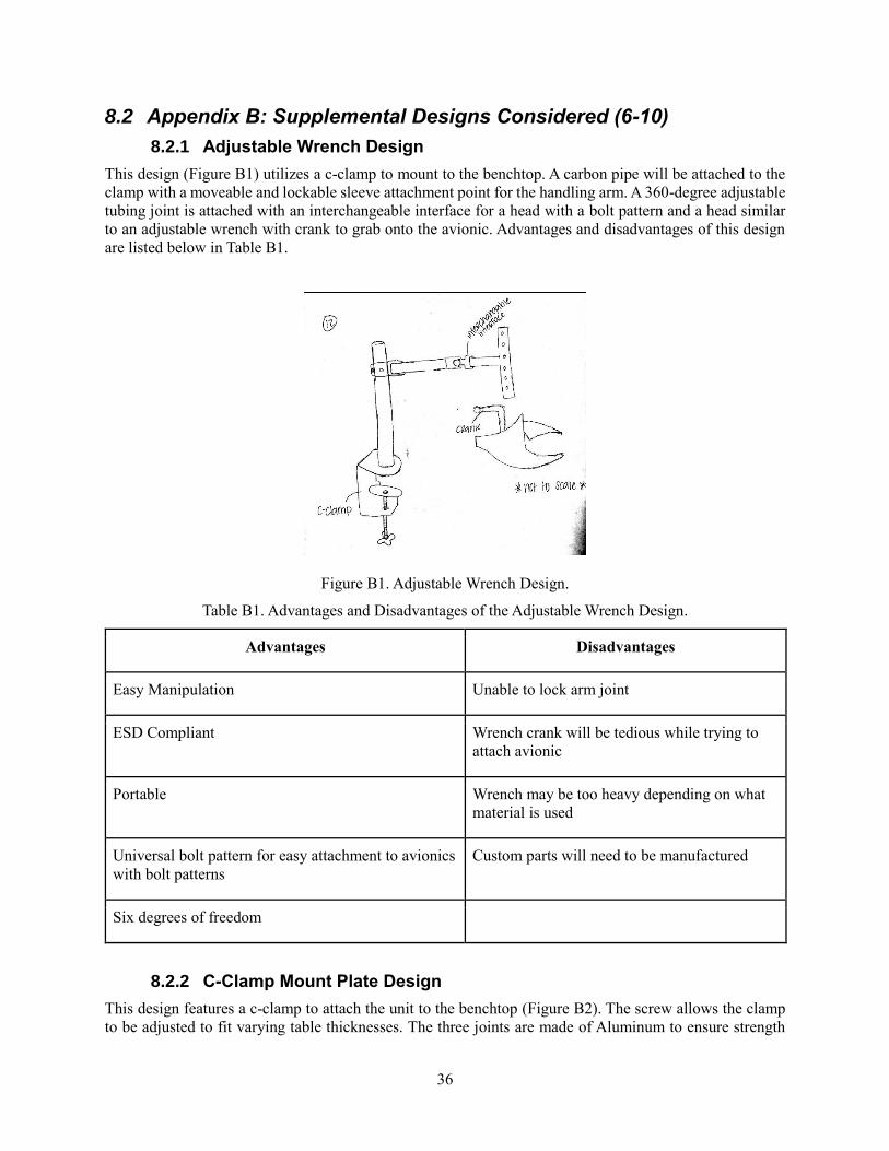
36
8.2 Appendix B: Supplemental Designs Considered (6-10)
8.2.1 Adjustable Wrench Design
This design (Figure B1) utilizes a c-clamp to mount to the benchtop. A carbon pipe will be attached to the
clamp with a moveable and lockable sleeve attachment point for the handling arm. A 360-degree adjustable
tubing joint is attached with an interchangeable interface for a head with a bolt pattern and a head similar
to an adjustable wrench with crank to grab onto the avionic. Advantages and disadvantages of this design
are listed below in Table B1.
Figure B1. Adjustable Wrench Design.
Table B1. Advantages and Disadvantages of the Adjustable Wrench Design.
Advantages Disadvantages
Easy Manipulation Unable to lock arm joint
ESD Compliant Wrench crank will be tedious while trying to
attach avionic
Portable Wrench may be too heavy depending on what
material is used
Universal bolt pattern for easy attachment to avionics
with bolt patterns
Custom parts will need to be manufactured
Six degrees of freedom
8.2.2 C-Clamp Mount Plate Design
This design features a c-clamp to attach the unit to the benchtop (Figure B2). The screw allows the clamp
to be adjusted to fit varying table thicknesses. The three joints are made of Aluminum to ensure strength
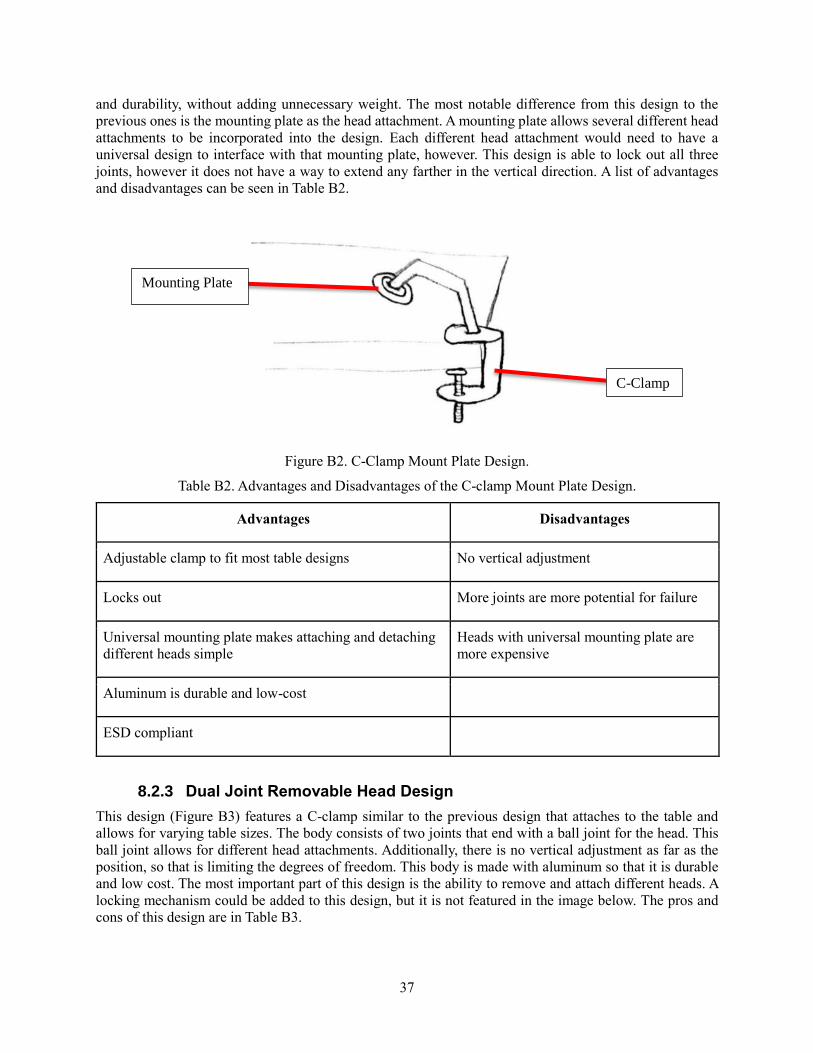
37
and durability, without adding unnecessary weight. The most notable difference from this design to the
previous ones is the mounting plate as the head attachment. A mounting plate allows several different head
attachments to be incorporated into the design. Each different head attachment would need to have a
universal design to interface with that mounting plate, however. This design is able to lock out all three
joints, however it does not have a way to extend any farther in the vertical direction. A list of advantages
and disadvantages can be seen in Table B2.
Figure B2. C-Clamp Mount Plate Design.
Table B2. Advantages and Disadvantages of the C-clamp Mount Plate Design.
Advantages Disadvantages
Adjustable clamp to fit most table designs No vertical adjustment
Locks out More joints are more potential for failure
Universal mounting plate makes attaching and detaching
different heads simple
Heads with universal mounting plate are
more expensive
Aluminum is durable and low-cost
ESD compliant
8.2.3 Dual Joint Removable Head Design
This design (Figure B3) features a C-clamp similar to the previous design that attaches to the table and
allows for varying table sizes. The body consists of two joints that end with a ball joint for the head. This
ball joint allows for different head attachments. Additionally, there is no vertical adjustment as far as the
position, so that is limiting the degrees of freedom. This body is made with aluminum so that it is durable
and low cost. The most important part of this design is the ability to remove and attach different heads. A
locking mechanism could be added to this design, but it is not featured in the image below. The pros and
cons of this design are in Table B3.
C-Clamp
Mounting Plate
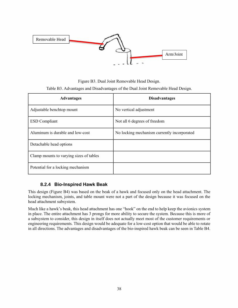
38
Figure B3. Dual Joint Removable Head Design.
Table B3. Advantages and Disadvantages of the Dual Joint Removable Head Design.
Advantages Disadvantages
Adjustable benchtop mount No vertical adjustment
ESD Compliant Not all 6 degrees of freedom
Aluminum is durable and low-cost No locking mechanism currently incorporated
Detachable head options
Clamp mounts to varying sizes of tables
Potential for a locking mechanism
8.2.4 Bio-Inspired Hawk Beak
This design (Figure B4) was based on the beak of a hawk and focused only on the head attachment. The
locking mechanism, joints, and table mount were not a part of the design because it was focused on the
head attachment subsystem.
Much like a hawk’s beak, this head attachment has one “hook” on the end to help keep the avionics system
in place. The entire attachment has 3 prongs for more ability to secure the system. Because this is more of
a subsystem to consider, this design in itself does not actually meet most of the customer requirements or
engineering requirements. This design would be adequate for a low-cost option that would be able to rotate
in all directions. The advantages and disadvantages of the bio-inspired hawk beak can be seen in Table B4.
Arm/Joint
Removable Head
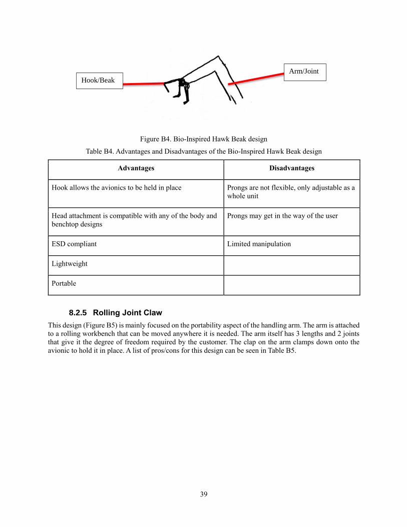
39
Figure B4. Bio-Inspired Hawk Beak design
Table B4. Advantages and Disadvantages of the Bio-Inspired Hawk Beak design
Advantages Disadvantages
Hook allows the avionics to be held in place Prongs are not flexible, only adjustable as a
whole unit
Head attachment is compatible with any of the body and
benchtop designs
Prongs may get in the way of the user
ESD compliant Limited manipulation
Lightweight
Portable
8.2.5 Rolling Joint Claw
This design (Figure B5) is mainly focused on the portability aspect of the handling arm. The arm is attached
to a rolling workbench that can be moved anywhere it is needed. The arm itself has 3 lengths and 2 joints
that give it the degree of freedom required by the customer. The clap on the arm clamps down onto the
avionic to hold it in place. A list of pros/cons for this design can be seen in Table B5.
Hook/Beak
Arm/Joint

40
Figure B5. Rolling Joint Claw.
Table B5. Advantages and Disadvantages of the Rolling Joint Claw Design.
Advantages Disadvantages
Claws hold avionic to arm The arm can be adjusted in height, secured to table
Rolling design allows for easy
mobility/portability
Square claws do not allow for oddly shaped objects
Joints on arm allow for 6 degrees of
freedom
Joints do not lock at one place, each joint must be locked
individually
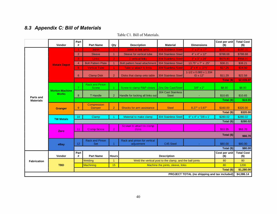
40
8.3 Appendix C: Bill of Materials
Table C1. Bill of Materials.
Vendor Part
# Part Name Qty Description Material Dimensions Cost per unit
($) Total Cost
($)
Parts and Materials
Metals Depot
1 Joints 1 Joints to link arms 304 Stainless Steel 2" x 2" x 12" $197.00 $197.00
2 Sleeve 1 Sleeve for vertical tube 304 Stainless Steel 4" x 4" x 12" $788.68 $788.68
3 Links 2 2 vertical links 304 Stainless Steel 3" x 3" x 24" $479.45 $958.90
4 Bolt Pattern Plate 1 Bolt pattern head attachment 304 Stainless Steel 13.75" x 7" x .25" $38.21 $38.21
5 Vertical Tube 1 Tube to attach to links 304 Stainless Steel 2" x 4" x .375" $17.25 $34.50
6 Clamp Disk 2 Disks that clamp onto table 304 Stainless Steel 1-1/2 x 0.083 x 1.334
ID x 12" $11.29 $22.58
Total ($) $2,039.87
Morton Machine Works
7 Rack and Pinion
Screw 1 Screw to clamp R&P closes Zinc Die Cast/Steel 3/8" x 2" $8.90 $8.90
8 T Handle 2 Handle for locking all links out 304 Cast Stainless
Steel - $10.65 $10.65
Total ($) $19.55
Granger 9 Compression
Damper 2 Shocks for arm assistance Steel 8.27" x 0.87" $160.00 $320.00
Total ($) $320.00
TW Metals 10 Clamp 1 Material to make clamp 304 Stainless Steel 6" x 4" x "3/8 x 1' $280.02 $280.02
Total ($) $280.02
Zoro 11 Clamp Screw 2
Screws to attach to clamp disks - - $33.35 $66.70
Total ($) $66.70
eBay 12 Rack and Pinion
Set 1 Rack and pinion for vertical
adjustment C45 Steel - $80.00 $80.00
Total ($) $80.00
Fabrication
Vendor Part
# Part Name Hours Description Cost per unit
($) Total Cost
($)
TBD
Welding 1 Weld the vertical post to the clamp, and the ball joints 80 80
Machining 15 Machine the joints, sleeve, links 80 1200
Total ($) $1,280.00
PROJECT TOTAL (no shipping and tax included) $4,086.14
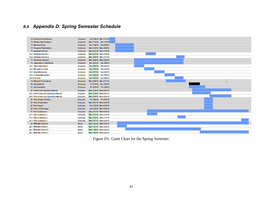
41
8.4 Appendix D: Spring Semester Schedule
Figure D1. Gantt Chart for the Spring Semester.