C A R B O N x x x ( 2 0 1 4 ) x x x – x x x
.sc ienced i rec t .com
Avai lab le a t wwwScienceDirect
journal homepage: www.elsevier .com/ locate /carbon
Nitrogen ion casting on vertically aligned carbonnanotubes: Tip and sidewall chemical modification
http://dx.doi.org/10.1016/j.carbon.2014.05.0350008-6223/� 2014 Elsevier Ltd. All rights reserved.
* Corresponding author.E-mail address: [email protected] (C. Bittencourt).
Please cite this article in press as: Scardamaglia M et al. Nitrogen ion casting on vertically aligned carbon nanotubes: Tip and sidewamodification. Carbon (2014), http://dx.doi.org/10.1016/j.carbon.2014.05.035
M. Scardamaglia a, M. Amati b, B. Llorente b, P. Mudimela c, J.-F. Colomer c, J. Ghijsen d,C. Ewels e, R. Snyders a,f, L. Gregoratti b, C. Bittencourt a,*
a Chemistry of Plasma-Surface Interaction (ChIPS), (CIRMAP), University of Mons, Belgiumb Elettra Sincrotrone Trieste S.C.p.A., AREA Science Park, Italyc Research Group on Carbon Nanostructures (CARBONNAGe), University of Namur, Belgiumd Research Centre in Physics of Matter and Radiation, University of Namur, Belgiume Institut des Materiaux Jean Rouxel, Universite de Nantes, CNRS, Nantes, Francef Materia Nova Research Center, Mons, Belgium
A R T I C L E I N F O
Article history:
Received 6 March 2014
Accepted 13 May 2014
Available online xxxx
A B S T R A C T
Nitrogen inclusion in vertically aligned carbon nanotubes (v-CNTs) was performed in situ
and in ultra-high vacuum by nitrogen ion implantation and evaluated by X-ray photoelec-
tron spectromicroscopy. The creation of defects induced by the ions drives the formation of
different nitrogen species (pyridinic, pyrrolic, and graphitic) at the CNT surface. While
nitrogen implantation in CNT sidewalls has results similar to implantation in graphene,
where mainly nitrogen sp2 bonding configuration occurs, we observed a different behav-
iour at the CNT tips, where nitrogen incorporation is also more efficient. A large amount
of pyrrolic nitrogen is observed at the CNT tips compared to the amount at the CNT
sidewalls for the same ion implantation parameters. This indicates a different reactivity
of the CNT tips where the presence of natural defects may be involved in different nitrogen
bonding formations between carbon and nitrogen with respect to the CNT sidewalls.
� 2014 Elsevier Ltd. All rights reserved.
1. Introduction
Chemical doping with foreign atoms is an effective method to
tune electronic and mechanical properties of a material for
optimizing a target application, to produce local changes in
elemental composition and to manipulate surface chemistry.
For carbon materials, chemical doping is also a leading
potential strategy to increase free charge-carrier density and
improve the electrical and thermal conductivity [1,2]. Among
the potential dopants of carbon materials, nitrogen with its
five valence electrons available for bonding is an outstanding
element for chemical doping of carbon nanotubes (CNTs) and
graphene [3–6]. N doping has been used to modify the elec-
tronic properties of carbon nanotubes [4,7–10] and reported
applications of nitrogen doped CNTs include gas [11] and bio
[12] sensors, energy-storage systems [13–15], oxygen reduction
reactions [16,17] and engineering of 3D macrostructures [18].
Due to the simplicity and one-pot technique, most reports
focus on CNT growth-doping via nitrogen-based feedstocks
during chemical vapour deposition (CVD) [19]. However, this
synthesis technique suffers from several limitations, for
example in multi-wall carbon nanotubes (MWCNTs) it results
in a very inhomogeneous distribution of nitrogen (high
concentration in interior walls and at ‘bridges’), it also
ll chemical
C B
A
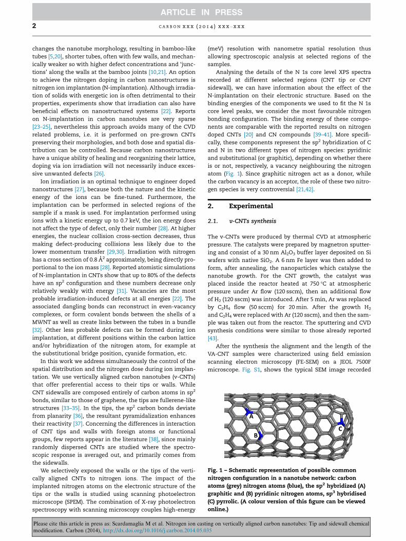
Fig. 1 – Schematic representation of possible common
nitrogen configuration in a nanotube network: carbon
atoms (grey) nitrogen atoms (blue), the sp2 hybridized (A)
graphitic and (B) pyridinic nitrogen atoms, sp3 hybridised
(C) pyrrolic. (A colour version of this figure can be viewed
online.)
2 C A R B O N x x x ( 2 0 1 4 ) x x x – x x x
changes the nanotube morphology, resulting in bamboo-like
tubes [5,20], shorter tubes, often with few walls, and mechan-
ically weaker so with higher defect concentrations and ‘junc-
tions’ along the walls at the bamboo joints [10,21]. An option
to achieve the nitrogen doping in carbon nanostructures is
nitrogen ion implantation (N-implantation). Although irradia-
tion of solids with energetic ion is often detrimental to their
properties, experiments show that irradiation can also have
beneficial effects on nanostructured systems [22]. Reports
on N-implantation in carbon nanotubes are very sparse
[23–25], nevertheless this approach avoids many of the CVD
related problems, i.e. it is performed on pre-grown CNTs
preserving their morphologies, and both dose and spatial dis-
tribution can be controlled. Because carbon nanostructures
have a unique ability of healing and reorganizing their lattice,
doping via ion irradiation will not necessarily induce exces-
sive unwanted defects [26].
Ion irradiation is an optimal technique to engineer doped
nanostructures [27], because both the nature and the kinetic
energy of the ions can be fine-tuned. Furthermore, the
implantation can be performed in selected regions of the
sample if a mask is used. For implantation performed using
ions with a kinetic energy up to 0.7 keV, the ion energy does
not affect the type of defect, only their number [28]. At higher
energies, the nuclear collision cross-section decreases, thus
making defect-producing collisions less likely due to the
lower momentum transfer [29,30]. Irradiation with nitrogen
has a cross section of 0.8 A2 approximately, being directly pro-
portional to the ion mass [28]. Reported atomistic simulations
of N-implantation in CNTs show that up to 80% of the defects
have an sp2 configuration and these numbers decrease only
relatively weakly with energy [31]. Vacancies are the most
probable irradiation-induced defects at all energies [22]. The
associated dangling bonds can reconstruct in even-vacancy
complexes, or form covalent bonds between the shells of a
MWNT as well as create links between the tubes in a bundle
[32]. Other less probable defects can be formed during ion
implantation, at different positions within the carbon lattice
and/or hybridization of the nitrogen atom, for example at
the substitutional bridge position, cyanide formation, etc.
In this work we address simultaneously the control of the
spatial distribution and the nitrogen dose during ion implan-
tation. We use vertically aligned carbon nanotubes (v-CNTs)
that offer preferential access to their tips or walls. While
CNT sidewalls are composed entirely of carbon atoms in sp2
bonds, similar to those of graphene, the tips are fullerene-like
structures [33–35]. In the tips, the sp2 carbon bonds deviate
from planarity [36], the resultant pyramidalization enhances
their reactivity [37]. Concerning the differences in interaction
of CNT tips and walls with foreign atoms or functional
groups, few reports appear in the literature [38], since mainly
randomly dispersed CNTs are studied where the spectro-
scopic response is averaged out, and primarily comes from
the sidewalls.
We selectively exposed the walls or the tips of the verti-
cally aligned CNTs to nitrogen ions. The impact of the
implanted nitrogen atoms on the electronic structure of the
tips or the walls is studied using scanning photoelectron
microscope (SPEM). The combination of X-ray photoelectron
spectroscopy with scanning microscopy couples high-energy
Please cite this article in press as: Scardamaglia M et al. Nitrogen ion castmodification. Carbon (2014), http://dx.doi.org/10.1016/j.carbon.2014.05.0
(meV) resolution with nanometre spatial resolution thus
allowing spectroscopic analysis at selected regions of the
samples.
Analysing the details of the N 1s core level XPS spectra
recorded at different selected regions (CNT tip or CNT
sidewall), we can have information about the effect of the
N-implantation on their electronic structure. Based on the
binding energies of the components we used to fit the N 1s
core level peaks, we consider the most favourable nitrogen
bonding configuration. The binding energy of these compo-
nents are comparable with the reported results on nitrogen
doped CNTs [20] and CN compounds [39–41]. More specifi-
cally, these components represent the sp2 hybridization of C
and N in two different types of nitrogen species: pyridinic
and substitutional (or graphitic), depending on whether there
is or not, respectively, a vacancy neighbouring the nitrogen
atom (Fig. 1). Since graphitic nitrogen act as a donor, while
the carbon vacancy is an acceptor, the role of these two nitro-
gen species is very controversial [21,42].
2. Experimental
2.1. v-CNTs synthesis
The v-CNTs were produced by thermal CVD at atmospheric
pressure. The catalysts were prepared by magnetron sputter-
ing and consist of a 30 nm Al2O3 buffer layer deposited on Si
wafers with native SiO2. A 6 nm Fe layer was then added to
form, after annealing, the nanoparticles which catalyse the
nanotube growth. For the CNT growth, the catalyst was
placed inside the reactor heated at 750 �C at atmospheric
pressure under Ar flow (120 sscm), then an additional flow
of H2 (120 sscm) was introduced. After 5 min, Ar was replaced
by C2H4 flow (50 sccm) for 20 min. After the growth H2
and C2H4 were replaced with Ar (120 sscm), and then the sam-
ple was taken out from the reactor. The sputtering and CVD
synthesis conditions were similar to those already reported
[43].
After the synthesis the alignment and the length of the
VA-CNT samples were characterized using field emission
scanning electron microscopy (FE-SEM) on a JEOL 7500F
microscope. Fig. S1, shows the typical SEM image recorded
ing on vertically aligned carbon nanotubes: Tip and sidewall chemical35
C A R B O N x x x ( 2 0 1 4 ) x x x – x x x 3
on our v-CNTs. The samples synthesized are typically
close-packed, well-aligned CNTs of 150 lm thick, i.e. the
multi-walled CNTs composing the carpets have on average
a dozen walls for 150 lm in length.
Prior to the measurements the samples were degassed up
to 400–500 �C in UHV.
2.2. Ion implantation
The ion implantation was performed in situ in the UHV
preparation chamber of the Escamicroscopy beamline at the
ELETTRA Synchrotron Radiation laboratory in Trieste (Italy),
using a Tectra plasma source. In this source, a nitrogen plasma
is created in a coaxial waveguide by evanescent wave coupling
of microwave energy at 2.45 GHz and enhanced by the electron
cyclotron resonance action of a quadrupole magnetic field.
A total acceleration voltage of 1 kV (extractor at �0.2 kV and
anode at +0.8 kV) was used to accelerate the ions towards
the sample; the fast ions induce defects in the sample, essen-
tial for the nitrogen implantation. During the nitrogen func-
tionalization, the base N2 gas pressure in the chamber was
1 · 10�4 mbar. The preparation chamber is connected to the
analysis chamber which has a base pressure of 10�10 mbar
allowing long analysis time without contamination.
Samples were cleaved in air prior to insertion in the vac-
uum chamber. They were mounted with different geometry:
one with the tips of the aligned CNTs facing the nitrogen
ion beam and the other sidewalls (cross section). The implan-
tation was performed in the normal direction. The current on
the sample during the treatment was of the order of 170 nA
with an ion current density of approximately 1013 ions/s cm2.
2.3. SPEM
The X-ray scanning photoelectron microscope (SPEM) avail-
able at Escamicroscopy was used to identify the regions to
be investigated by XPS.
The SPEM can operate in two modes [44,45]: in imaging
mode it is possible to obtain imaging by mapping simulta-
neously a selected kinetic energy window by exploiting the
48-channel electron detector; in spectroscopy mode it is
possible to acquire conventional XPS spectra from a 100 nm
wide confined region of interest by taking advantage of the
micro-spot resulting from the demagnifying action of a
Fresnel zone plate on the X-ray beam produced by the
synchrotron storage ring.
The photon energy used was 490 eV to maximize the sur-
face sensitivity and avoid the emission of the N 1s photoelec-
tron in the same energy range of the emission of the carbon
KLL Auger electron.
C 1s and N 1s core level spectra were recorded with an
overall energy resolution of 0.2 eV and 0.35 eV respectively.
Binding energies were calibrated using the Au 4f peaks from
a gold sample as a reference.
Concerning the fitting procedure, all the peaks (C 1s and
N 1s) were fitted by symmetric Voigt profile components,
exception for the sp2 C–C peaks that was fitted with a
Doniach-Sunjic asymmetric lineshape convoluted with a
Gaussian.
Please cite this article in press as: Scardamaglia M et al. Nitrogen ion castmodification. Carbon (2014), http://dx.doi.org/10.1016/j.carbon.2014.05.0
3. Results and discussion
XPS is a surface sensitive technique that can be effectively
used to evaluate chemical changes on the CNT surface
induced upon nitrogen implantation. In the XPS survey spec-
trum recorded on pristine v-CNTs the only peak at 284.4 eV
corresponds to photoelectrons emitted from the carbon C 1s
core level (Fig. 2a). The broad structure at around 280 eV is
due to C KLL Auger emission. After N-implantation, in the
survey spectrum (Fig. 2a), we can observe that a new peak
appears at �400 eV corresponding to photoelectrons emitted
from the nitrogen N 1s core level and, associated to this, the
broad structure at 115 eV is due to N KLL Auger emission.
Survey spectra were recorded after each N-implantation step.
From these spectra we evaluated the nitrogen content by con-
sidering the area under the C 1s and N 1s peaks and their pho-
toionization cross section at the given photon energy (490 eV).
The results are reported in Fig. 2b. These results suggest that
for the ion implantation parameters used the relative amount
of nitrogen incorporated in the sample reaches near to 19.5%
after 115 min of implantation. In Fig. 2b we can observe that
for the same implantation time the amount of nitrogen
incorporated is different at the CNT tips and walls: nitrogen
incorporation is more effective at the tips than at the side-
walls, as expected due to the higher CNT tip reactivity [38].
While top view analysis can be performed with standard
XPS, the nanotube sidewalls require a spatially resolved XPS
spectro-microscope, allowing the nanoscale spatial resolution
to discriminate a region of interest. Fig. 3 shows two SPEM
images of side ion implanted v-CNTs after 15 min (panel a)
and 90 min (panel b) of implantation. These images were
recorded by collecting photoelectron emitted from the N 1s
core level, nominally at 91 eV kinetic energy. The disordered
bundles into the foreground are due to the manual cleaving
of the sample made just before the insertion in the vacuum
chamber in order to have a fresh surface with regions of
well-aligned CNTs. Behind the disordered bundles we can
clearly see the vertically aligned carbon nanotubes; after the
ion implantation we did not observe any macroscopic change
on the morphology of the samples. The contrast in the two
images is dominated by sample topography: the brightest sig-
nal is coming from closer, out of focus, CNTs; standard topo-
graphical contribution removal procedures applied to the
images together with the spectroscopic characterization of
several local points along the v-CNTs sidewalls did not reveal
any significant change in the N content over different regions
of sample, suggesting uniform nitrogen implantation.
The nanoscale spot size of the incident X-ray beam in the
SPEM microscope allows to record the XPS spectra along the
cross sections of the v-CNTs, in order to probe their sidewalls.
The C 1s core levels of the pristine v-CNTs recorded on their
sidewalls and tips are substantially identical and reported in
the Supplementary information (Fig. S2), they are very repre-
sentative of a pristine sp2 carbon nanostructure with a small
amount of amorphous sp3 carbon typical of the CVD synthesis.
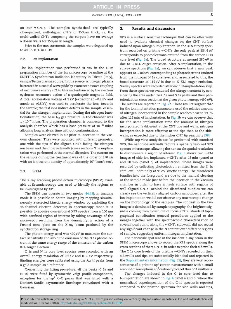
The changes induced in the C 1s core level due to
N-implantation are shown in Fig. 4 panel a and b, where the
normalized superimposition of the C 1s spectra is reported
compared to the pristine spectrum for side walls and tips,
ing on vertically aligned carbon nanotubes: Tip and sidewall chemical35

Fig. 2 – (a) Top-view XPS survey spectra comparison between pristine (dotted black line) and N-implanted (solid blue line) v-
CNTs, measured with 490 eV photon energy. (b) Nitrogen content as a function of implantation time from CNT tips (blue
circles) and CNT sidewalls (red squares) v-CNTs. (A colour version of this figure can be viewed online.)
Fig. 3 – 82 · 52 lm2 N 1s images of vertically aligned CNTs after N-implantation for (a) 15 min and (b) 90 min. The contrast
translates the sample topography: the brightest signal represents the region of the sample out of focus (closer to the
analyser). (A colour version of this figure can be viewed online.)
4 C A R B O N x x x ( 2 0 1 4 ) x x x – x x x
respectively. For increasing ion implantation time the C 1s
peak broadens as new components appear at both the lower
and higher binding energy side of the pristine peak. Moreover,
the binding energy position of the maximum intensity of the
C 1s peak, associated with photoelectrons emitted from car-
bon atoms in C–C sp2 bonds, shifts towards higher binding
energy. To quantify the energy shifts and the broadening we
used a least-square fitting procedure to analyse the C 1s core
level spectrum recorded at each step of the ion implantation
and the results are summarized in Table 1. The component at
284.1 eV binding energy (in light green in Fig. 4 panels c and d)
is associated to the creation of defects in the carbon network
due to ion implantation: the photoelectrons emitted from car-
bon atoms participating to these defects, mainly vacancies,
display a chemical shift to lower binding energies due to
Jahn–Teller symmetry-breaking distortion [46]. The relative
area of this component remains nearly constant for increas-
ing ion implantation time, more specifically it ranges from
11% to 15% without any correlation with implantation time
or region of analysis (i.e., CNT tip or CNT sidewall), indicating
that, for the implantation parameters used, the CNTs are not
Please cite this article in press as: Scardamaglia M et al. Nitrogen ion castmodification. Carbon (2014), http://dx.doi.org/10.1016/j.carbon.2014.05.0
further damaged when the implantation time is increased.
Similarly, for increasing ion implantation time, the compo-
nent at about 284.9 eV binding energy, associated to emission
from carbon atoms in sp3-bonding, increased with respect to
the pristine v-CNTs and its relative contribution value
saturated at 32% and 25% on the CNT sidewalls and CNT tips,
respectively. This difference will be discussed later together
with the N 1s core level spectra.
The effect of the N-implantation is evident in the variation
of the relative intensity of the components necessary to fit the
high-binding energy side of the C 1s, shown in blue in Fig. 4
panels c and d: their relative intensity increases for increasing
ion implantation time, generating a shoulder in the spectrum
taken from the CNT tips, clearly seen in Fig. 4d, which corre-
sponds to the highest nitrogen amount attained (19.5 at.%). It
is not straightforward to relate these new components in the
N-implanted C 1s spectrum to the corresponding C–N bonds.
Based on literature reports the component at 285.6 eV is most
commonly attributed to sp2 C@N while the one at 286.6 eV is
assigned to sp3 C–N [47,48]. A most likely justification of this
assumption comes from the relative area percentage of sp2
ing on vertically aligned carbon nanotubes: Tip and sidewall chemical35
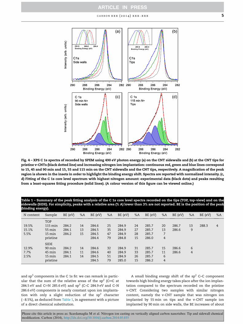
Fig. 4 – XPS C 1s spectra of recorded by SPEM using 490 eV photon energy (a) on the CNT sidewalls and (b) at the CNT tips for
pristine v-CNTs (black dotted line) and increasing nitrogen ion implantation: continuous red, green and blue lines correspond
to 15, 45 and 90 min and 15, 55 and 115 min on the CNT sidewalls and the CNT tips, respectively. A magnification of the peak
region is shown in the insets in order to highlight the binding energy shift. Spectra are reported with normalized intensity. (c,
d) Fitting of the C 1s core level spectrum with highest nitrogen amount: experimental data (black dots) and peaks resulting
from a least-squares fitting procedure (solid lines). (A colour version of this figure can be viewed online.)
Table 1 – Summary of the peak fitting analysis of the C 1s core level spectra recorded on the tips (TOP, top-view) and on thesidewalls (SIDE). For simplicity, peaks with a relative area (% A) lower than 3% are not reported. BE is the position of the peak(binding energy).
N content Sample BE (eV) %A BE (eV) %A BE (eV) %A BE (eV) %A BE (eV) %A BE (eV) %A
TOP19.5% 115 min 284.2 14 284.6 25 284.9 24 285.7 20 286.7 13 288.3 415.1% 55 min 284.1 13 284.5 35 284.9 27 285.7 13 286.6 95.5% 15 min 284.2 15 284.5 47 284.9 28 285.7 7
pristine 284.4 79 284.8 15 286.0 4
SIDE12.9% 90 min 284.2 14 284.6 32 284.9 31 285.7 15 286.6 67.7% 45 min 284.1 11 284.6 40 284.9 33 285.7 11 286.6 42.5% 15 min 284.1 14 284.5 51 284.9 26 285.7 6
pristine 284.5 79 285.0 15 286.2 4
C A R B O N x x x ( 2 0 1 4 ) x x x – x x x 5
and sp3 components in the C 1s fit: we can remark in partic-
ular that the sum of the relative areas of the sp2 (C@C at
284.5 eV and C@N 285.6 eV) and sp3 (C–C 284.9 eV and C–N
286.6 eV) components is nearly constant upon ion implanta-
tion with only a slight reduction of the sp2 character
(�8.5%), as deduced from Table 1, in agreement with a picture
of a direct chemical substitution.
Please cite this article in press as: Scardamaglia M et al. Nitrogen ion castmodification. Carbon (2014), http://dx.doi.org/10.1016/j.carbon.2014.05.0
A small binding energy shift of the sp2 C–C component
towards high binding energy takes place after the ion implan-
tation compared to the spectrum recorded on the pristine
v-CNT. Considering two samples with similar nitrogen
content, namely the v-CNT sample that was nitrogen ion
implanted by 55 min on tips and the v-CNT sample ion
implanted by 90 min on side walls, the BE increases of about
ing on vertically aligned carbon nanotubes: Tip and sidewall chemical35
6 C A R B O N x x x ( 2 0 1 4 ) x x x – x x x
130 meV in the first case and 70 meV for the second one. The
difference in the value of the energy shift is due to different
nitrogen bonding configurations present in these two regions
(CNT tips and CNT side walls), as will be discussed later.
These shifts are in agreement with n-type doping observed
by XPS for nitrogen introduction into sp2 carbon nanostruc-
tures as graphene [6], multiwalled carbon nanotubes [49]
and carbon nanofibers [50].
Important information comes from the analysis of N 1s
core levels recorded after each N-implantation step. In
Fig. 5a, we can identify three main components in the N 1s
core level spectra, named N1, N2 and N3, which are related
to different bonding configurations of nitrogen atoms into
the carbon lattice. Table 2 summarizes the result of the fitting
of the N 1s spectra recorded after each ion implantation step.
The N1 component is associated with pyridinic nitrogen,
Fig. 5 – (a) N 1s core level spectra measured with 490 eV photon
and 90 min nitrogen ions treatment from bottom to top, respec
graphitic-valley and N5 pyridinic-oxide (see Fig. 1); experimenta
procedure (solid red line). A Shirley-type background was subtr
stacked for clarity. (b) Variation in the relative area of the differen
function of ion implantation time. (A colour version of this figu
Table 2 – Summary of the peak fitting analysis of the N 1s coreside-walls (SIDE). N1 is pyridinic, N2 pyrrolic, N3 graphitic-centthe relative area, BE is the position of the peak (binding energy
N content Sample BE (eV) %A BE (eV) %AN1 N2
TOP19.5% 115 min 398.3 14 399.2 4215.1% 55 min 398.5 13 399.1 435.5% 15 min 398.2 20 399.1 29
SIDE12.9% 90 min 398.4 34 399.3 87.7% 45 min 398.4 26 399.3 122.5% 15 min 398.1 26 399.3 8
Please cite this article in press as: Scardamaglia M et al. Nitrogen ion castmodification. Carbon (2014), http://dx.doi.org/10.1016/j.carbon.2014.05.0
a nitrogen atom with two aromatic carbon neighbours. This
can occur next to a vacancy, or at an edge site, for example
at an open nanotube tip [21]. The N2 component is associated
with pyrrolic nitrogen [48,51,52], substitutional nitrogen in a
region of defective non-aromatic lattice (such as neighbour-
ing pentagons and/or heptagons) [53] or sp cyanide (triple
bonded to carbon) [39,54–56]. This component can be a super-
imposition of many different contributions, for the precise
identification of its nature a correlation of XPS with other
techniques, such as X-ray absorption, is necessary [39]. The
component N3 is due to graphitic nitrogen, where the N atom
takes the place of a C atom. Two other minor components at
higher binding energy can be identified in the N 1s spectra:
they are named as N4 (�402.5 eV) and N5 (�404.2 eV). They
both can be associated with contributions coming from
N-oxide groups [48,57,58]. Part of the contribution to N4 may
energy from the sidewalls of v-CNTs corresponding to 5, 45
tively. N1 is pyridinic, N2 pyrrolic, N3 graphitic-center, N4
l data (dotted line), peaks resulting from a least-square fitting
acted. Spectra are reported with normalized intensity and
t components used to reproduce the nitrogen spectrum as a
re can be viewed online.)
level spectra recorded on the tips (TOP, top-view) and on theer, N4 graphitic-valley, N5 pyridinic-oxide (see Fig. 1), % A is).
BE (eV) %A BE (eV) %A BE (eV) %AN3 N4 N5
400.7 34 402.2 6 403.8 4400.7 34 402.3 7 404.0 3400.6 38 402.2 10 404.0 4
400.9 45 402.8 9 404.5 3400.9 48 402.8 10 404.5 3400.9 50 402.8 14 404.5 1
ing on vertically aligned carbon nanotubes: Tip and sidewall chemical35
C A R B O N x x x ( 2 0 1 4 ) x x x – x x x 7
also be due to the presence of ‘‘graphitic valley’’ nitrogen
[57,59], that is graphitic nitrogen close to an edge. This attri-
bution of the N4 component gains additional support consid-
ering that the variation of its relative area for increasing
implantation time has the same trend of component N3 rela-
tive area, as we can see from Figs. 5b and 6b. An additional
contribution to N4 could be small amounts of molecular
nitrogen trapped between the CNT walls [56,60,61]. Since the
relative area of this component is always less than 5% in all
recorded N 1s spectra, we will not consider it further.
The different types of nitrogen bonding configuration at
the sidewalls of the v-CNTs and the effect of increasing ion
implantation time in the relative intensity of the components
used to fit their contribution in the N 1s core level are similar
to reported results for graphene [6,48]. The graphitic/pyridinic
ratio decreases for increasing ion dose due to increasing num-
bers of defects (mainly vacancies) created during the ion
implantation. This is expected since the sidewalls of CNTs
can be seen as rolled up graphene sheets, as seen by the high
concentration of sp2 species: graphitic components at first
and pyridinic. The appearance of the component N2 associ-
ated with defect formation can be induced by the sputtering
and recoil of C atoms between the graphitic walls of the car-
bon nanotubes, creating inter-walls links mainly with tetra-
hedral hybridization [30,32,62,63]. This, together with Fig. 3,
shows that we are achieving a homogenous nitrogen implan-
tation, quite unlikely obtained in the CVD N-doped CNTs.
Additionally, the nitrogen ion implantation performed with
the parameters used affects mainly the outer walls of the
CNTs [28], differently from nitrogen doping during the CVD
growth.
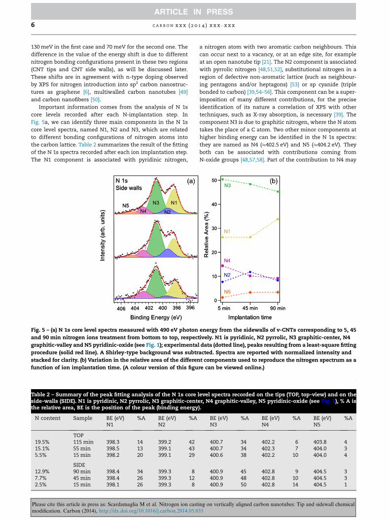
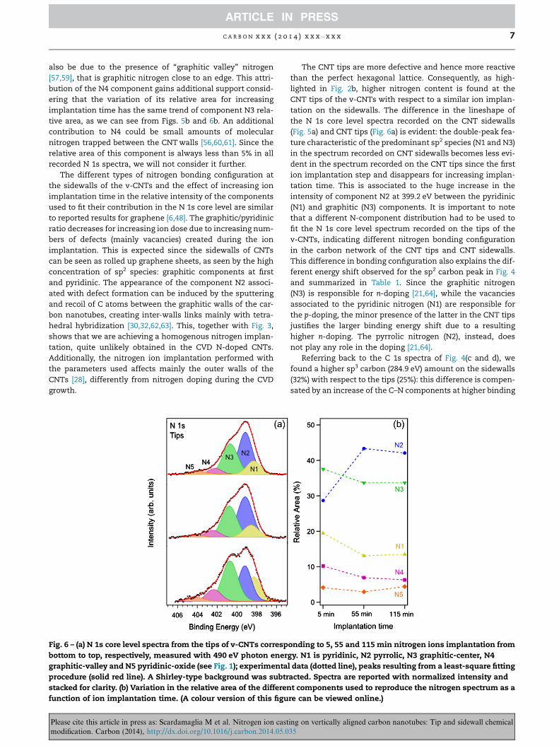
Fig. 6 – (a) N 1s core level spectra from the tips of v-CNTs corresp
bottom to top, respectively, measured with 490 eV photon energ
graphitic-valley and N5 pyridinic-oxide (see Fig. 1); experimenta
procedure (solid red line). A Shirley-type background was subtr
stacked for clarity. (b) Variation in the relative area of the differen
function of ion implantation time. (A colour version of this figu
Please cite this article in press as: Scardamaglia M et al. Nitrogen ion castmodification. Carbon (2014), http://dx.doi.org/10.1016/j.carbon.2014.05.0
The CNT tips are more defective and hence more reactive
than the perfect hexagonal lattice. Consequently, as high-
lighted in Fig. 2b, higher nitrogen content is found at the
CNT tips of the v-CNTs with respect to a similar ion implan-
tation on the sidewalls. The difference in the lineshape of
the N 1s core level spectra recorded on the CNT sidewalls
(Fig. 5a) and CNT tips (Fig. 6a) is evident: the double-peak fea-
ture characteristic of the predominant sp2 species (N1 and N3)
in the spectrum recorded on CNT sidewalls becomes less evi-
dent in the spectrum recorded on the CNT tips since the first
ion implantation step and disappears for increasing implan-
tation time. This is associated to the huge increase in the
intensity of component N2 at 399.2 eV between the pyridinic
(N1) and graphitic (N3) components. It is important to note
that a different N-component distribution had to be used to
fit the N 1s core level spectrum recorded on the tips of the
v-CNTs, indicating different nitrogen bonding configuration
in the carbon network of the CNT tips and CNT sidewalls.
This difference in bonding configuration also explains the dif-
ferent energy shift observed for the sp2 carbon peak in Fig. 4
and summarized in Table 1. Since the graphitic nitrogen
(N3) is responsible for n-doping [21,64], while the vacancies
associated to the pyridinic nitrogen (N1) are responsible for
the p-doping, the minor presence of the latter in the CNT tips
justifies the larger binding energy shift due to a resulting
higher n-doping. The pyrrolic nitrogen (N2), instead, does
not play any role in the doping [21,64].
Referring back to the C 1s spectra of Fig. 4(c and d), we
found a higher sp3 carbon (284.9 eV) amount on the sidewalls
(32%) with respect to the tips (25%): this difference is compen-
sated by an increase of the C–N components at higher binding
onding to 5, 55 and 115 min nitrogen ions implantation from
y. N1 is pyridinic, N2 pyrrolic, N3 graphitic-center, N4
l data (dotted line), peaks resulting from a least-square fitting
acted. Spectra are reported with normalized intensity and
t components used to reproduce the nitrogen spectrum as a
re can be viewed online.)
ing on vertically aligned carbon nanotubes: Tip and sidewall chemical35

8 C A R B O N x x x ( 2 0 1 4 ) x x x – x x x
energies. This can be understood as defective sites generated
at the tips during the ion bombardment becoming partially
occupied by the N atoms, which does not happen on the
sidewalls. A gradual opening of the tips of v-CNTs upon long
time (30 min) oxygen plasma exposure has been reported [38],
when the samples were in the post-discharge region where
only few charged heavy particles and hot electrons are pres-
ent [65]. In our case the ion implantation may also break
bonds at the CNT tips, in this picture where the tips are open
there will be dangling bonds and notably a loss of aromaticity
with many reconstructions (i.e. pentagons, heptagons,. . .) and
the pyrrolic-type component (N2) at 399.2 eV will therefore
have a much higher intensity. Those reconstructions on the
tips also explain why the component associated to the pyrid-
inic nitrogen (N1) is less intense in the spectra recorded at the
CNT tips than in the CNT side walls.
4. Conclusions
Due to the nanoscale spatial resolution achieved by the
scanning photoelectron microscopy we were able to follow
the chemical changes induced by nitrogen ion implantation
on v-CNTs along their cross-section (i.e. sidewalls) and on
the CNT tips. Performing the ion implantation in situ and
in UHV assure a clean and reproducible way to obtain high
nitrogen concentrations in carbon nanomaterials with a
post-synthesis technique. The N-implantation results are
different between the tips and the sidewalls: we remark a
higher amount of nitrogen incorporation on the tips where
the N 1s core level lose its double-peak lineshape due to the
predominance of graphitic and pyridinic species, while we
observed a huge increase of the pyrrolic nitrogen, mostly
linked to defects. Although the nitrogen ion implantation
on the sidewalls maintains the sp2 character of the net-
work, on the tips the caps of the CNTs were broken. Since
an increase in the intensity of the pyridinic nitrogen com-
ponent was not observed, this opening cannot be explained
as a simple creation of edges terminated by nitrogen atoms,
but as a disordered reconstruction that takes place making
them also more reactive to foreign atoms and functional
groups.
Acknowledgements
This work was partially funded by the Directorate of Research
in Wallonia, under the scope of the ERA-NET MATERA pro-
gramme and the Belgian Fund for Scientific Research (FRS-
FNRS) under FRFC contract ‘‘Chemographene’’ (convention
no. 2.4577.11). Support from the COST action MP0901
‘‘NanoTP’’ is gratefully acknowledged. J.-F. Colomer and J.
Ghijsen are supported by the Belgian Fund for Scientific
Research (FSR-FNRS) as Research associates. C. Ewels
acknowledge ANR Nanosim-Graphene for funding.
Appendix A. Supplementary data
Supplementary data associated with this article can be found,
in the online version, at http://dx.doi.org/10.1016/j.carbon.
2014.05.035.
Please cite this article in press as: Scardamaglia M et al. Nitrogen ion castmodification. Carbon (2014), http://dx.doi.org/10.1016/j.carbon.2014.05.0
R E F E R E N C E S
[1] Ma Y, Foster A, Krasheninnikov AV, Nieminen R. Nitrogen ingraphite and carbon nanotubes: magnetism and mobility.Phys Rev B 2005;72:205416.
[2] Zhou C, Kong J, Yenilmez E, Dai H. Modulated chemicaldoping of individual carbon nanotubes. Science2000;290:1552–5.
[3] Jiao Q, Hao L, Shao Q, Zhao Y. In situ synthesis of iron-fillednitrogen-doped carbon nanotubes and their magneticproperties. Carbon 2013;61:647–9.
[4] Barzegar HR, Gracia-Espino E, Shari T, Nitze F, Wagberg T.Nitrogen doping mechanism in small diameter single-walledcarbon nanotubes: impact on electronic properties andgrowth selectivity. J Phys Chem C 2013;117:25805–16.
[5] Sharifi T, Nitze F, Barzegar HR, Tai C-W, Mazurkiewicz M,Malolepszy A, et al. Nitrogen doped multi walled carbonnanotubes produced by CVD-correlating XPS and Ramanspectroscopy for the study of nitrogen inclusion. Carbon2012;50:3535–41.
[6] Scardamaglia M, Aleman B, Amati M, Ewels CP, Pochet P,Reckinger N, et al. Nitrogen implantation of suspendedgraphene flakes: annealing effects and selectivity of sp2
nitrogen species. Carbon 2014;73:371–81.[7] Lopez-Bezanilla A. Electronic and quantum transport
properties of substitutionally doped double-walled carbonnanotubes. J Phys Chem C 2014;118:1472–7.
[8] Tison Y, Lin H, Lagoute J, Repain V, Chacon C, Girard Y, et al.Identification of nitrogen dopants in single-walled carbonnanotubes by scanning tunneling microscopy. ACS Nano2013;7:7219–26.
[9] Alegaonkar AP, Kumar A, Patil SH, Patil KR, Pardeshi SK,Alegaonkar PS. Spin transport and magnetic correlationparameters for few layer graphene-like nanocarbon sheetsdoped with nitrogen. J Phys Chem C 2013;117:27105–13.
[10] Kanygin Ma, Sedelnikova OV, Asanov IP, Bulusheva LG,Okotrub aV, Kuzhir PP, et al. Effect of nitrogen doping on theelectromagnetic properties of carbon nanotube-basedcomposites. J Appl Phys 2013;113:144315.
[11] Adjizian J-J, Leghrib R, Koos Aa, Suarez-Martinez I, CrossleyA, Wagner P, et al. Boron- and nitrogen-doped multi-wallcarbon nanotubes for gas detection. Carbon 2014;66:662–73.
[12] Sheng Q, Liu R, Zheng J. Fullerene-nitrogen doped carbonnanotubes for the direct electrochemistry of hemoglobin andits application in biosensing. Bioelectrochemistry2013;94:39–46.
[13] Mi R, Liu H, Wang H, Wong K-W, Mei J, Chen Y, et al. Effects ofnitrogen-doped carbon nanotubes on the dischargeperformance of Li-air batteries. Carbon 2014;67:744–52.
[14] Li Y, Feng Y, Feng W. Deeply fluorinated multi-wall carbonnanotubes for high energy and power densities lithium/carbon fluorides battery. Electrochim Acta 2013;107:343–9.
[15] Hussain S, Amade R, Jover E, Bertran E. Nitrogen plasmafunctionalization of carbon nanotubes for supercapacitorapplications. J Mater Sci 2013;48:7620–8.
[16] Zhao A, Masa J, Schuhmann W, Xia W. Activation andstabilization of nitrogen-doped Carbon nanotubes aselectrocatalysts in the oxygen reduction reaction at stronglyalkaline conditions. J Phys Chem C 2013;117:24283–91.
[17] Tang Y, Burkert SC, Zhao Y, Saidi WA, Star A. The effect ofmetal catalyst on the electrocatalytic activity of nitrogen-doped carbon nanotubes. J Phys Chem C 2013;117:25213–21.
[18] Shan C, Zhao W, Lu XL, O’Brien DJ, Li Y, Cao Z, et al. Three-dimensional nitrogen-doped multiwall carbon nanotubesponges with tunable properties. Nano Lett 2013;13:5514–20.
[19] Ayala P, Gruneis A, Gemming T, Grimm D, Kramberger C,Rummeli MH, et al. Tailoring N-doped single and double wall
ing on vertically aligned carbon nanotubes: Tip and sidewall chemical35

C A R B O N x x x ( 2 0 1 4 ) x x x – x x x 9
carbon nanotubes from a nondiluted carbon/nitrogenfeedstock. J Phys Chem C 2007;111:2879–84.
[20] Liu H, Zhang Y, Li R, Sun X, Desilets S, Abou-Rachid H, et al.Structural and morphological control of aligned nitrogen-doped carbon nanotubes. Carbon 2010;48:1498–507.
[21] Ewels CP, Glerup M. Nitrogen doping in carbon nanotubes. JNanosci Nanotechnol 2005;5:1345–63.
[22] Krasheninnikov AV, Nordlund K. Irradiation effects in carbonnanotubes. Nucl Instrum Methods Phys Res Sect B2004;216:355–66.
[23] Xu F, Minniti M, Barone P, Sindona A, Bonanno A, Oliva A.Nitrogen doping of single walled carbon nanotubes by lowenergy ion implantation. Carbon 2008;46:1489–96.
[24] Morant C, Torres R, Jimenez I, Sanz JM, Elizalde E.Characterization of nitrogen-doped carbon nanotubes byatomic force microscopy, X-ray photoelectron spectroscopyand X-ray absorption near edge spectroscopy. J NanosciNanotechnol 2008;8:1–6.
[25] Kamimura T, Yamamoto K, Matsumoto K. Effects of ultralow energy nitrogen Ion irradiation on carbon nanotubechannel single-electron transistor. Jpn J Appl Phys2004;43:2771–3.
[26] Berber S, Oshiyama A. Reconstruction of mono-vacancies incarbon nanotubes: atomic relaxation vs. spin polarization.Phys B Condens Matter 2006;376–377:272–5.
[27] Krasheninnikov AV, Banhart F. Engineering of nanostructuredcarbon materials with electron or ion beams. Nat Mater2007;6:723–33.
[28] Krasheninnikov AV, Nordlund K. Ion and electron irradiation-induced effects in nanostructured materials. J Appl Phys2010;107:071301.
[29] Krasheninnikov AV, Nordlund K, Sirvio M, Salonen E,Keinonen J. Formation of ion-irradiation-induced atomic-scale defects on walls of carbon nanotubes. Phys Rev B2001;63:245405.
[30] Krasheninnikov AV, Nordlund K, Keinonen J. Production ofdefects in supported carbon nanotubes under ion irradiation.Phys Rev B 2002;65:165423.
[31] Kotakoski J, Krasheninnikov AV, Ma Y, Foster A, Nordlund K,Nieminen R. B and N ion implantation into carbonnanotubes: insight from atomistic simulations. Phys Rev B2005;71:205408.
[32] Salonen E, Krasheninnikov AV, Nordlund K. Ion-irradiation-induced defects in bundles of carbon nanotubes. NuclInstrum Methods Phys Res Sect B 2002;193:603–8.
[33] Suzuki S, Watanabe Y, Kiyokura T, Nath K, Ogino T,Heun S, et al. Electronic structure at carbon nanotube tipsstudied by photoemission spectroscopy. Phys Rev B2001;63:245418.
[34] Pincak R, Osipov Va. Localized electron states near pentagonsin variously shaped carbon nanoparticles. Phys Lett A2003;314:315–21.
[35] Carroll D, Redlich P, Ajayan P, Charlier J, Blase X, De Vita A,et al. Electronic structure and localized states at carbonnanotube tips. Phys Rev Lett 1997;78:2811–4.
[36] Haddon RC. Electronic structure, conductivity andsuperconductivity of alkali metal doped (C60). Acc Chem Res1992;25:127–33.
[37] Prato M. [60] Fullerene chemistry for materials scienceapplications. J Mater Chem 1997;7:1097–109.
[38] Bittencourt C, Navio C, Nicolay A, Ruelle B, Godfroid T,Snyders R, et al. Atomic oxygen functionalization ofvertically aligned carbon nanotubes. J Phys Chem C2011;115:20412–8.
[39] Ripalda JM, Roman E, Diaz N, Galan L, Montero I, Comelli G,et al. Correlation of X-ray absorption and X-rayphotoemission spectroscopies in amorphous carbon nitride.Phys Rev B 1999;60:3705–8.
Please cite this article in press as: Scardamaglia M et al. Nitrogen ion castmodification. Carbon (2014), http://dx.doi.org/10.1016/j.carbon.2014.05.0
[40] Ronning C, Feldermann H, Merk R, Hofsass H, Reinke P,Thiele JU. Carbon nitride deposited using energetic species: areview on XPS studies. Phys Rev B 1998;58:2207.
[41] Souto S, Pickholz M, Santos MC, Alvarez F. Electronicstructure of nitrogen-carbon alloys a-CN x determined byphotoelectron spectroscopy. Phys Rev B 1998;57:2536–40.
[42] Ayala P, Arenal R, Rummeli M, Rubio A, Pichler T. The dopingof carbon nanotubes with nitrogen and their potentialapplications. Carbon 2010;48:575–86.
[43] Colomer J-F, Ruelle B, Moreau N, Lucas S, Snyders R, GodfroidT, et al. Vertically aligned carbon nanotubes: synthesis andatomic oxygen functionalization. Surf Coat Technol2011;205:S592–6.
[44] Marsi M, Casalis L, Gregoratti L, Gu S, Kolmakov A, Kovac J,et al. ESCA Microscopy at ELETTRA: what it is like to performspectromicroscopy experiments on a third generationsynchrotron radiation source. J Electron Spectrosc RelatPhenom 1997;84:73–83.
[45] Abyaneh MK, Gregoratti L, Amati M, Dalmiglio M, KiskinovaM. Scanning photoelectron microscopy: a powerfultechnique for probing micro and nano-structures. E-J Surf SciNanotechnol 2011;9:158–62.
[46] Barinov A, Gregoratti L, Dudin P, La Rosa S, Kiskinova M.Imaging and spectroscopy of multiwalled carbon nanotubesduring oxidation: defects and oxygen bonding. Adv Mater2009;21:1916–20.
[47] Lin Y-C, Lin C-Y, Chiu P-W. Controllable graphene N-dopingwith ammonia plasma. Appl Phys Lett 2010;96:133110.
[48] Wang H, Maiyalagan T, Wang X. Review on recent progress innitrogen-doped graphene: synthesis, characterization, andits potential applications. ACS Catal 2012;2:781–94.
[49] Lim S, Elim H, Gao X, Wee A, Ji W, Lee J, et al. Electronic andoptical properties of nitrogen-doped multiwalled carbonnanotubes. Phys Rev B 2006;73:045402.
[50] Ismagilov ZR, Shalagina AE, Podyacheva OY, Ischenko AV,Kibis LS, Boronin AI, et al. Structure and electricalconductivity of nitrogen-doped carbon nanofibers. Carbon2009;47:1922–9.
[51] Casanovas J, Ricart JM, Rubio J, Illas F, Jime JM. Origin of theLarge N 1s binding energy in X-ray photoelectron spectra ofcalcined carbonaceous materials. JACS 1996;7863:8071–6.
[52] Arrigo R, Havecker M, Schlogl R, Su DS. Dynamic surfacerearrangement and thermal stability of nitrogen functionalgroups on carbon nanotubes. Chem Commun 2008:4891–3.
[53] Arenal R, March K, Ewels CP, Rocquefelte X, Kociak M, LoiseauA, et al. Atomic configuration of nitrogen-doped single-walledcarbon nanotubes. 2014; arXiv:1401.5007 [cond-mat.mtrl-sci].
[54] Kumar A, Ganguly A, Papakonstantinou P. Thermal stabilitystudy of nitrogen functionalities in a graphene network. JPhys Condens Matter 2012;24:235503.
[55] Shimoyama I, Wu G, Sekiguchi T, Baba Y. Evidence for theexistence of nitrogen-substituted graphite structure bypolarization dependence of NEXAFS. Phys Rev B2000;62:6053–6.
[56] Zhang L, Ye Y, Cheng D, Zhang W, Pan H, Zhu J. Simultaneousreduction and N-doping of graphene oxides by low-energyN2+ ion sputtering. Carbon 2013;62:365–73.
[57] Pels JR, Kapteijn F, Moulijn JA, Zhu Q, Thomas KM. Evolutionof nitrogen functionalities in carbonaceous materials duringpyrolysis. Carbon 1995;33:1641–53.
[58] Nagaiah TC, Kundu S, Bron M, Muhler M, Schuhmann W.Nitrogen-doped carbon nanotubes as a cathode catalyst forthe oxygen reduction reaction in alkaline medium.Electrochem Commun 2010;12:338–41.
[59] Sharifi T, Hu G, Jia X, Wagberg T. Formation of active sites foroxygen reduction reactions by transformation of nitrogenfunctionalities in nitrogen-doped carbon nanotubes. ACSNano 2012;6:8904–12.
ing on vertically aligned carbon nanotubes: Tip and sidewall chemical35
10 C A R B O N x x x ( 2 0 1 4 ) x x x – x x x
[60] Kim K-J, Lee H, Choi J, Lee H, Jung MC, Shin HJ, et al. Surfaceproperty change of graphene using nitrogen ion. J PhysCondens Matter 2010;22:045005.
[61] Droppa RJ, Hammer P, Carvalho ACM, dos Santos MC, AlvarezF. Incorporation of nitrogen in carbon nanotubes. J Non CrystSolids 2002;302:874–9.
[62] Ni B, Sinnott S. Chemical functionalization of carbonnanotubes through energetic radical collisions. Phys Rev B2000;61. R16343-6.
Please cite this article in press as: Scardamaglia M et al. Nitrogen ion castmodification. Carbon (2014), http://dx.doi.org/10.1016/j.carbon.2014.05.0
[63] Telling RH, Ewels CP, El-Barbary Aa, Heggie MI. Wignerdefects bridge the graphite gap. Nat Mater 2003;2:333–7.
[64] Robertson J, Davis CA. Nitrogen doping of tetrahedralamorphous carbon. Diamond Relat Mater 1995;4:441–4.
[65] Merel P, Tabbal M, Chaker M, Moisan M, Ricard A. Influence ofthe field frequency on the nitrogen atom yield in the remoteplasma of an high frequency discharge. Plasma Sources SciTechnol 1998;7:550.
ing on vertically aligned carbon nanotubes: Tip and sidewall chemical35