1 Approved for Public Release; No Export Controlled Data
ES-MVA-070714-0323 ©2014, July 07
All rights reserved
Next Generation Space Interconnect
Standard (NGSIS)
Efforts associated with the VPX and
RapidIO standards
Patrick Collier (AFRL) and Richard Berger (BAE Systems)

2 Approved for Public Release; No Export Controlled Data
ES-MVA-070714-0323 ©2014, July 07
All rights reserved
NGSIS Charter
Develop
• Vendor-independent, non-proprietary, system or
device design based on official and/or popular
standards.
Allow
• Vendors (in competition with one another) to create
add-on products that increase a system's (or device's)
flexibility, functionality, interoperability, potential use,
and useful life.
Enables
• Users to customize and extend a system's (or
device's) capabilities to suit individual requirements.
7/22/2014
3 Approved for Public Release; No Export Controlled Data
ES-MVA-070714-0323 ©2014, July 07
All rights reserved
NGSIS Members • Honeywell
• BAE Systems
• Harris
• Boeing
• Lockheed Martin
• Northrop Grumman
• Aeroflex
• SEAKR Engineering
• L3 Communications
• ELMA Bustronics
• Aerospace Corporation
• TE Connectivity
• Raytheon
• Smiths Connectors
• Amphenol
• IEH
• Curtiss-Wright
• NASA
• NASA/JPL
• NRL
• SMC-XR
• Microsemi
• Aeroflex
• Freescale
• Xilinx
• IDT
• Texas Instruments
• Mobiveil
• Orbital Sciences

4 Approved for Public Release; No Export Controlled Data
ES-MVA-070714-0323 ©2014, July 07
All rights reserved
VITA 78 (SpaceVPX)
5 Approved for Public Release; No Export Controlled Data
ES-MVA-070714-0323 ©2014, July 07
All rights reserved
SpaceVPX Goals
Develop
• Enhanced set of backplane specifications that are
based upon existing commercial standards with added
features required for space applications.
Increase
• Interoperability and compatibility between
manufacturers and integrators, while simultaneously
increasing affordability through the use of standard
sets of hardware.
7/22/2014

6 Approved for Public Release; No Export Controlled Data
ES-MVA-070714-0323 ©2014, July 07
All rights reserved
With That In Mind….
• The OpenVPX backplane standard has been chosen as the base
for the SpaceVPX backplane standardization effort.
• The SpaceVPX Systems Specification was created to bridge the VPX
standards to the space market.
• SpaceVPX is a space-capable variation of the [VITA 65] OpenVPX
industry standard developed as an element of the Next Generation
Space Interconnect Standard (NGSIS) working group.
• The primary focus is to enhance the OpenVPX standard with
features required by space applications, such as single-point failure
tolerance, spare module support, redundancy, management, and
status and diagnostic support.
7/22/2014

7 Approved for Public Release; No Export Controlled Data
ES-MVA-070714-0323 ©2014, July 07
All rights reserved
What is in it?
VITA 65
Fault Tolerance enhancements
VITA 46.3
SRIO on VPX VITA 46.9
PMC/XMC VITA 46.11
Sys. Management VITA 48.2
Conduction
SpaceVPX (VITA 78)
7/22/2014

8 Approved for Public Release; No Export Controlled Data
ES-MVA-070714-0323 ©2014, July 07
All rights reserved
Putting it All Together
Pa
ylo
ad
in
pu
t
Pro
ce
ss
ing
ca
rd
Pro
ce
ss
ing
ca
rd
Sw
itc
h c
ard
Me
mo
ry c
ard
Ou
tpu
t c
ard
Po
we
r c
ard
Pa
ylo
ad
in
pu
t
Pa
ylo
ad
in
pu
t
MILSATCOM System
Payload
Bus • Protocols: RapidIO, SpaceWire, I2C, etc.
VPX
1
VPX
2
VPX
3
VPX
7VPX
8
VPX
9VPX
4
VPX
6
Contrl
Plane
Contrl
Plane
Contrl
Plane
Contrl
Plane
Contrl
Plane
Contrl
Plane
IPMC IPMC IPMC IPMC IPMC IPMC
Contrl
Switch
Contrl
Switch
Power A and B
Switched
Management
Plane (IPMB)
Control Plane
(TP)
Data Plane
(DFP)
Slot
numbers
are logical,
physical
slot
numbers
may be
different
Payload slotsPayload slots
Switched
Utility Plane
Includes power
UM
5
Controller
Selection
A and B (HLD)
Data
Plane
Data
Plane
Data
Plane
Data
Plane
Data
Plane
Data
Plane
Data
Plane
Data
Plane
Expan
Plane
Expan
Plane
Expan
Plane
Expan
Plane
Expan
Plane
Expan
Plane
SW
ChMC ChMC
TP
TP
Contr
ol S
lot
Contr
ol S
lot
SpaecU
MS
lots
7/22/2014
9 Approved for Public Release; No Export Controlled Data
ES-MVA-070714-0323 ©2014, July 07
All rights reserved
SpaceVPX Fault Tolerance The goal of SpaceVPX is to achieve an acceptable level of fault tolerance while maintaining reasonable compatibility with OpenVPX components, including connector pin assignments. For the purposes of fault tolerance, a module is considered the minimum redundancy element. The Utility Plane, Management Plane, and Control Plane are all distributed redundantly and in star topologies to provide fault tolerance.
For space applications, the major fault tolerance requirements are listed below:
• Dual-redundant power distribution (bussed) (Section 3) where each distribution is supplied from an independent power source.
• Dual-redundant management distribution (point-to-point cross-strapped) where each distribution is supplied from an independent management controller to a SpaceUM module that selects between the A and B management controllers for distribution to each of the slots controlled by the SpaceUM module.
• Card-level serial management (Section 3)
• Card-level reset control
• Card-level power control
• Timing/synchronization/clocks, matched length, low-skew differential (Section 3)
• Fault tolerant Utility Plane and Management Plane selection (bussed) (Section 3)
• Dual-redundant data planes (point-to-point cross-strapped)
• Dual-Redundant control planes (point-to-point cross-strapped) (Section 3)
7/22/2014
10 Approved for Public Release; No Export Controlled Data
ES-MVA-070714-0323 ©2014, July 07
All rights reserved
RapidIO protocol overview

11 Approved for Public Release; No Export Controlled Data
ES-MVA-070714-0323 ©2014, July 07
All rights reserved
RapidIO overview
• Proven technology > 10 years of market deployment
• Standard products and synthesizable IP cores available from
multiple commercial suppliers
• Key benefits vs. alternative protocols
– Highly scalable, peer to peer, multi-processor fabric
– Scalable fabric for board, backplane and inter-chassis communication
– Designed for the unique requirements of multiprocessor systems
– Superior end-to-end packet latency, throughput and fault tolerance
– Lowest overall system power
• High speed serial links
– Currently available: 1.25 up through 6.25 Gbps/lane - 25 Gbps/port (4x) embedded RapidIO on CPUs, DSPs, FPGAs and ASICs
– 10 Gbps/lane specification (10xN) released Q4 2013 (Rev. 3.0)
– 25 Gbps/lane (25xN) next gen work initiated
• Hardware termination at PHY layer
• Lowest latency interconnect ~ 100 ns
• Inherently scales to large systems
April 2014
RapidIO Switch
FPGA DSP CPU
RapidIO Switch
• More than 45 million 10-20 Gbps ports shipped
• 100% 4G/LTE interconnect market share; 60% Global 3G interconnect market share
• Strong market penetration in high performance computing and the Mil/Aero markets
Lowest latency
Scalability
Performance
Lowest power

12 Approved for Public Release; No Export Controlled Data
ES-MVA-070714-0323 ©2014, July 07
All rights reserved
Hardware terminated vs TCP offload
• RapidIO protocols are terminated in
hardware, offloading the processor of
protocol termination tasks
• The end result is:
• Reduction in latency
• Better throughput
• Lower power
• Frees up processor cycles
• Higher performing systems
April 2014
Imp
lem
en
ted
in H
ard
ware

13 Approved for Public Release; No Export Controlled Data
ES-MVA-070714-0323 ©2014, July 07
All rights reserved
RapidIO packet format
• Logical
– Logical layer format delineated by four
bit Ftype field, listed as “TYPES” in the
specification
– Transaction field indicates the specific
request or response type
– All other fields dependent on Ftype and
Transaction
• Transport
– RapidIO uses source based addressing
– Switches use route tables to determine destination port
– TT field indicates size of route address
– A destination may have more than one target address for redundant routes
• Physical
– Physical layer adds device to device
handshake info
– Packet partitioned to simplify
assembly/disassembly in controllers
16 8 to 256 Bytes
8, 16, or 32 8, 16, or 32 2 4 4
8 4 32, 48, 64
CRC Next Packet Optional Data Payload
TT Target
Address
Source
Address Ftype
Size Source
TID
Transaction Physical Bits Previous
Packet
Device Offset Address
Physical Transport Logical
14 Approved for Public Release; No Export Controlled Data
ES-MVA-070714-0323 ©2014, July 07
All rights reserved
RapidIO physical layer specification
Logical Specifications
Transport Specifications
Physical Specifications
Ancillary Specifications
Parallel Serial
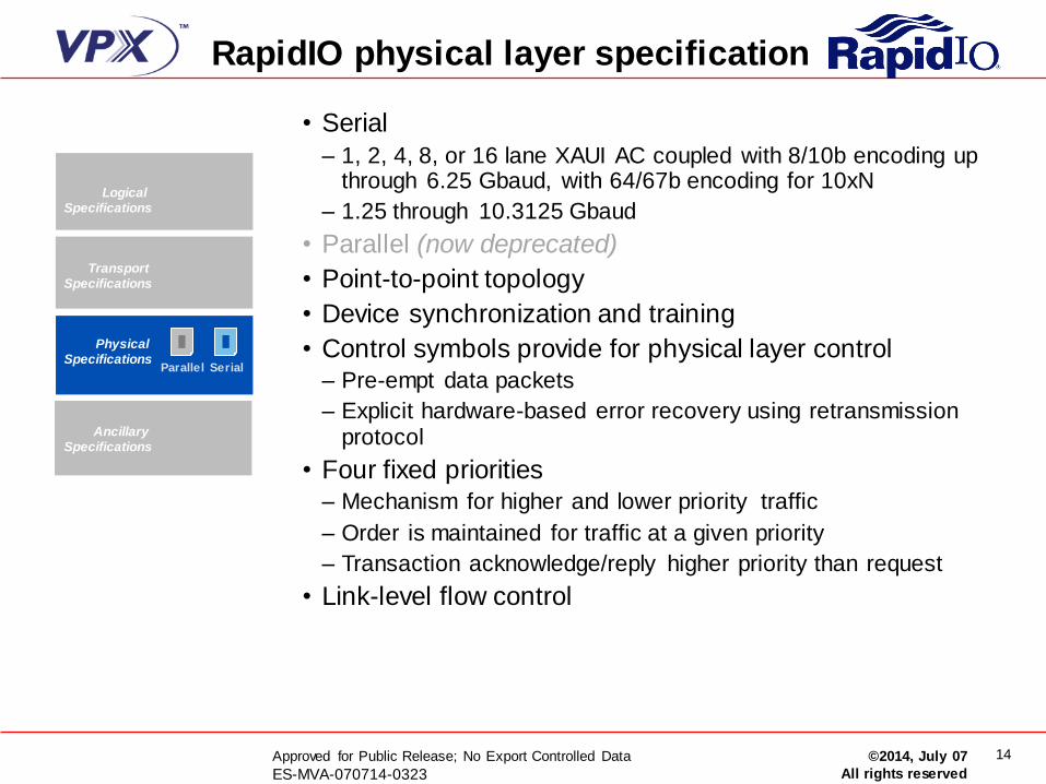
• Serial
– 1, 2, 4, 8, or 16 lane XAUI AC coupled with 8/10b encoding up through 6.25 Gbaud, with 64/67b encoding for 10xN
– 1.25 through 10.3125 Gbaud
• Parallel (now deprecated)
• Point-to-point topology
• Device synchronization and training
• Control symbols provide for physical layer control – Pre-empt data packets
– Explicit hardware-based error recovery using retransmission protocol
• Four fixed priorities – Mechanism for higher and lower priority traffic
– Order is maintained for traffic at a given priority
– Transaction acknowledge/reply higher priority than request
• Link-level flow control

15 Approved for Public Release; No Export Controlled Data
ES-MVA-070714-0323 ©2014, July 07
All rights reserved
Transport specification
• Switches operate at the transport layer – All logical protocols use a common transport header
– Today’s switches will work with future logical protocols
• Device-based routing – 8, 16, or 32 bit device ID
• Simplifies classification and routing compared to Ethernet or IP
– Any RapidIO device ID can be used as a unicast ID or a multicast group • Unicast packets are forwarded out a single port
• Multicast packets are forwarded to multiple ports (No ACK NWRITE, SWRITE, Data Streaming)
– Fail-over events only affect routing table entries of nearest neighbors
Logical Specifications
Transport Specifications
Physical Specifications
Ancillary Specifications
Common Transport
Multicast
16 Approved for Public Release; No Export Controlled Data
ES-MVA-070714-0323 ©2014, July 07
All rights reserved
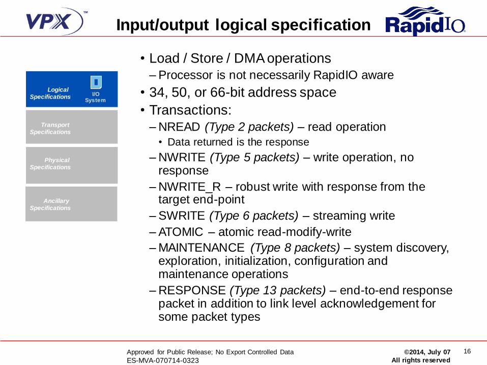
Input/output logical specification
• Load / Store / DMA operations
– Processor is not necessarily RapidIO aware
• 34, 50, or 66-bit address space
• Transactions:
– NREAD (Type 2 packets) – read operation
• Data returned is the response
– NWRITE (Type 5 packets) – write operation, no response
– NWRITE_R – robust write with response from the target end-point
– SWRITE (Type 6 packets) – streaming write
– ATOMIC – atomic read-modify-write
– MAINTENANCE (Type 8 packets) – system discovery, exploration, initialization, configuration and maintenance operations
– RESPONSE (Type 13 packets) – end-to-end response packet in addition to link level acknowledgement for some packet types
Logical Specifications
Transport Specifications
Physical Specifications
Ancillary Specifications
I/O System
17 Approved for Public Release; No Export Controlled Data
ES-MVA-070714-0323 ©2014, July 07
All rights reserved
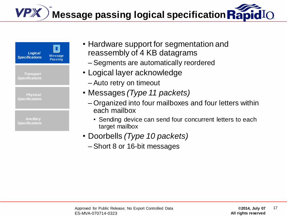
Message passing logical specification
• Hardware support for segmentation and reassembly of 4 KB datagrams
– Segments are automatically reordered
• Logical layer acknowledge
– Auto retry on timeout
• Messages (Type 11 packets)
– Organized into four mailboxes and four letters within each mailbox
• Sending device can send four concurrent letters to each target mailbox
• Doorbells (Type 10 packets)
– Short 8 or 16-bit messages
Logical Specifications
Transport Specifications
Physical Specifications
Ancillary Specifications
Message Passing

18 Approved for Public Release; No Export Controlled Data
ES-MVA-070714-0323 ©2014, July 07
All rights reserved
Data streaming logical specification
• Type 9 packets
• Segmentation and reassembly – Up to 64KB protocol data units (PDUs)
– System-wide maximum transmission unit (MTU) size
• Efficient logical protocol for communications – Start, continuation, and end segments
• Continuation has 20 bit header, increasing transmission efficiency
• Interworking – Encapsulation of other protocols, such as Ethernet,
UTOPIA, SPI-3/4, CSIX, etc.
• Virtual streams – Flow identification
• Traffic management framework – End-to-end flow control
– Millions of streams
– 256 traffic classes – Lossy operations
• No logical layer acknowledge to support traffic managed data plane applications
Logical Specifications
Transport Specifications
Physical Specifications
Ancillary Specifications
Data Streaming
19 Approved for Public Release; No Export Controlled Data
ES-MVA-070714-0323 ©2014, July 07
All rights reserved
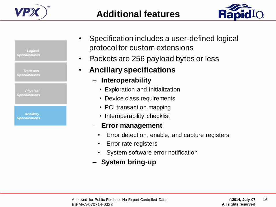
Additional features
• Specification includes a user-defined logical
protocol for custom extensions
• Packets are 256 payload bytes or less
• Ancillary specifications
– Interoperability
• Exploration and initialization
• Device class requirements
• PCI transaction mapping
• Interoperability checklist
– Error management
• Error detection, enable, and capture registers
• Error rate registers
• System software error notification
– System bring-up
Logical Specifications
Transport Specifications
Physical Specifications
Ancillary Specifications

20 Approved for Public Release; No Export Controlled Data
ES-MVA-070714-0323 ©2014, July 07
All rights reserved
New “Part S” features with
RapidIO Revision 3.1
21 Approved for Public Release; No Export Controlled Data
ES-MVA-070714-0323 ©2014, July 07
All rights reserved
The RapidIO “Part S” task group
• The NGSIS team selected the RapidIO protocol for adoption in 2012
• Working with the RapidIO Trade Association, a “Part S” Task group
was formed to develop a unique features for use in space applications
• Identified features were primarily to add robustness and fault
tolerance
• Because many of these apply to other applications as well, the Part S
features have been built into the existing RapidIO specification as
Revision 3.1
22 Approved for Public Release; No Export Controlled Data
ES-MVA-070714-0323 ©2014, July 07
All rights reserved
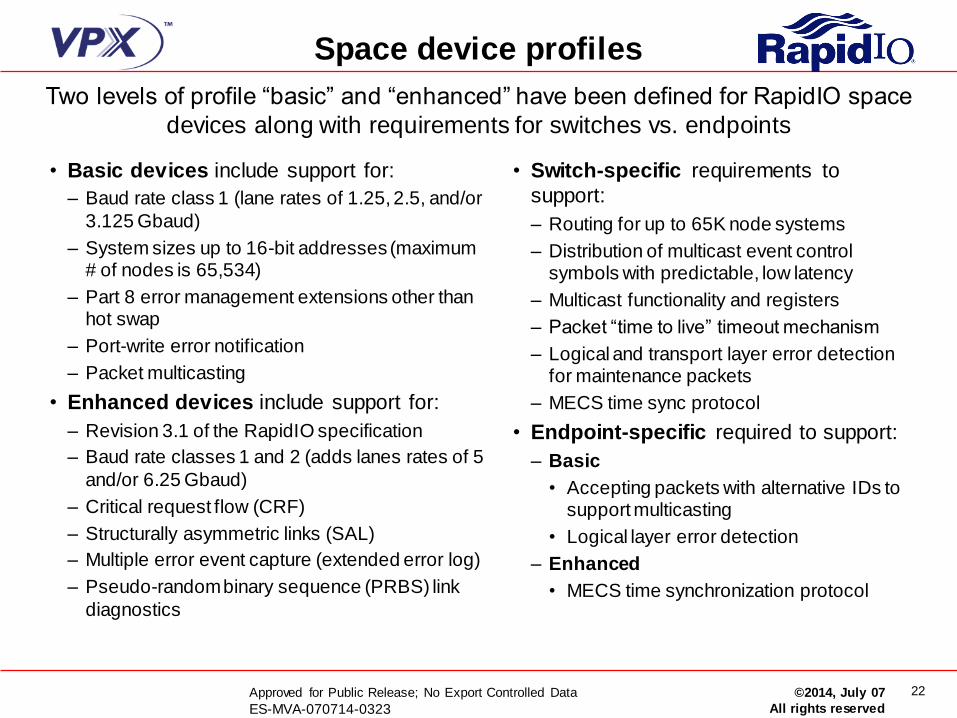
Space device profiles
• Basic devices include support for:
– Baud rate class 1 (lane rates of 1.25, 2.5, and/or
3.125 Gbaud)
– System sizes up to 16-bit addresses (maximum # of nodes is 65,534)
– Part 8 error management extensions other than hot swap
– Port-write error notification
– Packet multicasting
• Enhanced devices include support for:
– Revision 3.1 of the RapidIO specification
– Baud rate classes 1 and 2 (adds lanes rates of 5
and/or 6.25 Gbaud)
– Critical request flow (CRF)
– Structurally asymmetric links (SAL)
– Multiple error event capture (extended error log)
– Pseudo-random binary sequence (PRBS) link
diagnostics
• Switch-specific requirements to
support:
– Routing for up to 65K node systems
– Distribution of multicast event control symbols with predictable, low latency
– Multicast functionality and registers
– Packet “time to live” timeout mechanism
– Logical and transport layer error detection for maintenance packets
– MECS time sync protocol
• Endpoint-specific required to support:
– Basic
• Accepting packets with alternative IDs to support multicasting
• Logical layer error detection
– Enhanced
• MECS time synchronization protocol
Two levels of profile “basic” and “enhanced” have been defined for RapidIO space
devices along with requirements for switches vs. endpoints
23 Approved for Public Release; No Export Controlled Data
ES-MVA-070714-0323 ©2014, July 07
All rights reserved
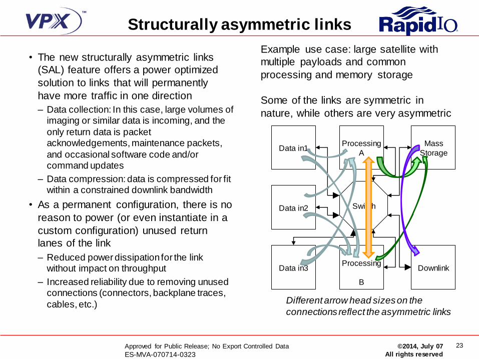
Structurally asymmetric links
• The new structurally asymmetric links
(SAL) feature offers a power optimized
solution to links that will permanently
have more traffic in one direction
– Data collection: In this case, large volumes of imaging or similar data is incoming, and the
only return data is packet acknowledgements, maintenance packets,
and occasional software code and/or command updates
– Data compression: data is compressed for fit within a constrained downlink bandwidth
• As a permanent configuration, there is no
reason to power (or even instantiate in a
custom configuration) unused return
lanes of the link
– Reduced power dissipation for the link without impact on throughput
– Increased reliability due to removing unused connections (connectors, backplane traces,
cables, etc.)
Data in3
Processing
A
Mass
Storage
Downlink
Switch
Processing
B
Data in2
Data in1
Different arrow head sizes on the
connections reflect the asymmetric links
Example use case: large satellite with
multiple payloads and common
processing and memory storage
Some of the links are symmetric in
nature, while others are very asymmetric
24 Approved for Public Release; No Export Controlled Data
ES-MVA-070714-0323 ©2014, July 07
All rights reserved
Fault tolerant enhancements to
port width degradation
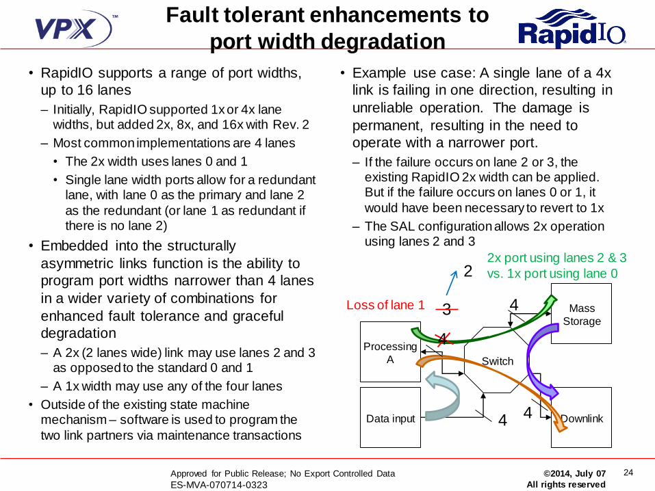
• RapidIO supports a range of port widths,
up to 16 lanes
– Initially, RapidIO supported 1x or 4x lane widths, but added 2x, 8x, and 16x with Rev. 2
– Most common implementations are 4 lanes
• The 2x width uses lanes 0 and 1
• Single lane width ports allow for a redundant lane, with lane 0 as the primary and lane 2
as the redundant (or lane 1 as redundant if there is no lane 2)
• Embedded into the structurally
asymmetric links function is the ability to
program port widths narrower than 4 lanes
in a wider variety of combinations for
enhanced fault tolerance and graceful
degradation
– A 2x (2 lanes wide) link may use lanes 2 and 3 as opposed to the standard 0 and 1
– A 1x width may use any of the four lanes
• Outside of the existing state machine mechanism – software is used to program the
two link partners via maintenance transactions
• Example use case: A single lane of a 4x
link is failing in one direction, resulting in
unreliable operation. The damage is
permanent, resulting in the need to
operate with a narrower port.
– If the failure occurs on lane 2 or 3, the existing RapidIO 2x width can be applied. But if the failure occurs on lanes 0 or 1, it
would have been necessary to revert to 1x
– The SAL configuration allows 2x operation using lanes 2 and 3
Data input
Mass
Storage
Downlink
Switch
Processing
A
4
4 4
3
4
2
Loss of lane 1
2x port using lanes 2 & 3
vs. 1x port using lane 0

25 Approved for Public Release; No Export Controlled Data
ES-MVA-070714-0323 ©2014, July 07
All rights reserved
Multicast event control symbol
(MECS) time sync/distribution • The ability to distribute time using the RapidIO
network eliminates the need for a secondary set of connections, which is of particular value to smaller satellite systems
– A comprehensive time distribution solution was
added in Revision 3.0 of the RapidIO specification (similar to the IEEE 1588 precision time protocol distribution standard)
– However, it required a large amount of hardware
for implementation to support very large networks with additional nodes added at any time
• A less hardware-intensive solution is possible for networks of contained size and with a known and
stable configuration
– MECS-based time sync is based on the use of a “tick” to provide the interval between time pulses
• Eliminates need for per port registers
• Eliminates need for unique mechanism for propagation of timestamp updates
– A secondary MECS signal (SMECS) can be
employed, sourced from a different component
– The SMECS redundant solution allows either
signal to act as the primary, supporting failover in the case of an interruption of the primary signal
for increased fault tolerance
Starting time
System
time master
RapidIO
switch
Port
Port
1)Write “Next Timestamp”
with Maintenance packets
2)Send MECS “Tick” to
start all timers “simultaneously”
Next
Time stamp
Write
Correcting
for drift System
time master
RapidIO
switch
Port
Port
Reception of MECS
triggers: A) Write of locally
computed “next time” to
timestamp generator B) Update locally
computed “next time” by adding one “Tick”
Next
Time stamp
Write
A B
Send MECS
Forward MECS

26 Approved for Public Release; No Export Controlled Data
ES-MVA-070714-0323 ©2014, July 07
All rights reserved
FIFO-based extended error log • Part 8 of the RapidIO specification addresses error
management, including the ability to capture and report an error
– Error detection, enable, and capture registers are provided for both the physical layer on a per port basis and at the logical layer
– Currently, the error capture registers at the physical and logical layers
are locked once an enabled error is detected, preventing the capture of additional errors until that error is read and cleared by software
– Without an extended error logging capability, the capture of a sequence of errors in the order they occurred would not be possible
• The extended error log provides for a variable-depth log
(constrained by the developer’s decision on memory allocation)
– Transparent to the current one-deep error log
– The existing registers represent the head of the FIFO, and each entry
represents the locked value of these registers at the time of the entry
– The existing error registers access the oldest occupied entry in the FIFO, and that entry becomes unoccupied when read by software and the corresponding control register bit(s) is cleared
– While the FIFO is full, additional detected errors are captured in a non-
locking holding register and may be overwritten while waiting for a FIFO entry to open up
– When the FIFO is no longer full, the most recently captured error is added to the FIFO – but some intermediate errors may have been lost
– Existing software is unchanged and interoperability is maintained with
existing hardware
Port n
Error
Detect
CSR
Port n
Error
Attribute
CSR
Port n
Error
Capture
CSRs
Port n
Error
Detect
FIFO
Entry 1
Port n
Error
Attribute
FIFO
Entry 1
Port n
Error
Capture
FIFO
Entry 1
Port n
Error
Detect
FIFO
Entry 2
Port n
Error
Attribute
FIFO
Entry 2
Port n
Error
Capture
FIFO
Entry 2
Port n
Error
Detect
FIFO
Entry n
Port n
Error
Attribute
FIFO
Entry n
Port n
Error
Capture
FIFO
Entry n
…
…
…
Port n
Error
Detect
holding
reg
Port n
Error
Attribute
holding
reg
Port n
Error
Capture
holding
reg
Port n
Error
Detect
CSR
27 Approved for Public Release; No Export Controlled Data
ES-MVA-070714-0323 ©2014, July 07
All rights reserved
Pseudo-random binary sequence
(PRBS) link testing/diagnostics
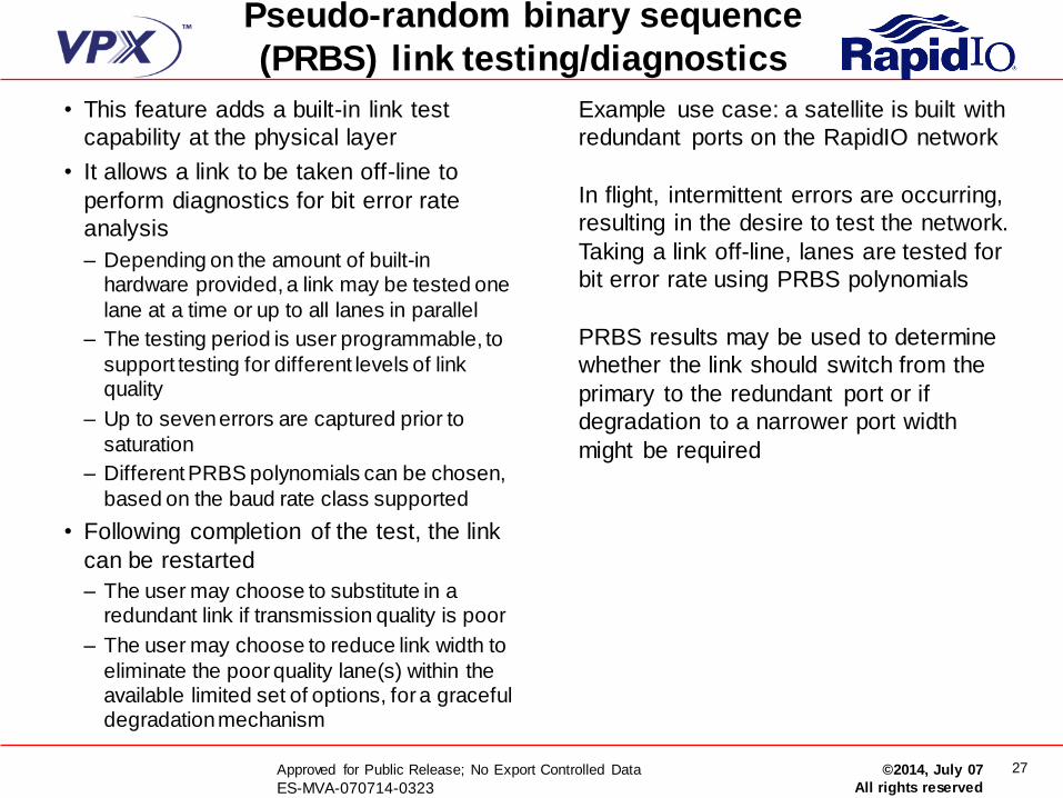
• This feature adds a built-in link test
capability at the physical layer
• It allows a link to be taken off-line to
perform diagnostics for bit error rate
analysis
– Depending on the amount of built-in hardware provided, a link may be tested one
lane at a time or up to all lanes in parallel
– The testing period is user programmable, to
support testing for different levels of link quality
– Up to seven errors are captured prior to
saturation
– Different PRBS polynomials can be chosen,
based on the baud rate class supported
• Following completion of the test, the link
can be restarted
– The user may choose to substitute in a redundant link if transmission quality is poor
– The user may choose to reduce link width to
eliminate the poor quality lane(s) within the available limited set of options, for a graceful degradation mechanism
Example use case: a satellite is built with
redundant ports on the RapidIO network
In flight, intermittent errors are occurring,
resulting in the desire to test the network.
Taking a link off-line, lanes are tested for
bit error rate using PRBS polynomials
PRBS results may be used to determine
whether the link should switch from the
primary to the redundant port or if
degradation to a narrower port width
might be required
28 Approved for Public Release; No Export Controlled Data
ES-MVA-070714-0323 ©2014, July 07
All rights reserved
Optional features made standard
for space RapidIO devices
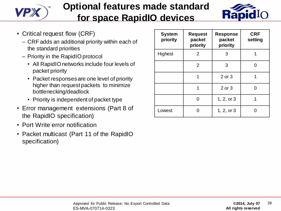
• Critical request flow (CRF)
– CRF adds an additional priority within each of
the standard priorities
– Priority in the RapidIO protocol
• All RapidIO networks include four levels of
packet priority
• Packet responses are one level of priority higher than request packets to minimize bottlenecking/deadlock
• Priority is independent of packet type
• Error management extensions (Part 8 of
the RapidIO specification)
• Port Write error notification
• Packet multicast (Part 11 of the RapidIO
specification)
System
priority
Request
packet
priority
Response
packet
priority
CRF
setting
Highest 2 3 1
2 3 0
1 2 or 3 1
1 2 or 3 0
0 1, 2, or 3 1
Lowest 0 1, 2, or 3 0
29 Approved for Public Release; No Export Controlled Data
ES-MVA-070714-0323 ©2014, July 07
All rights reserved
Timeline for standardization,
adoption, and implementation
• SpaceVPX
– Final version of VITA 78 has been written and is being voted upon
– Publication of VITA 78 specification is expected in Summer 2014
– Next generation products will be implemented to the SpaceVPX specification
• RapidIO
– Enhanced features have been integrated into RapidIO specification revision 3.1
– The revision is currently being voted upon and release is expected in Summer 2014
– The RapidIO Bus Functional Model (BFM) will be updated to reflect the Rev. 3.1
features, but the timeline is not yet defined
– Radiation hardened endpoint and switch products based on RapidIO are already in
development, but are not likely to reflect the Rev. 3.1 additions yet