C A R B O N 6 6 ( 2 0 1 4 ) 4 3 6 – 4 4 1
.sc iencedi rect .com
Avai lab le at wwwScienceDirect
journal homepage: www.elsev ier .com/ locate /carbon
New insights into the properties and interactionsof carbon chains as revealed by HRTEM andDFT analysis
0008-6223/$ - see front matter � 2013 Elsevier Ltd. All rights reserved.http://dx.doi.org/10.1016/j.carbon.2013.09.019
* Corresponding author: Fax: +1 210 458 6954.E-mail address: [email protected] (M. Jose-Yacaman).
Gilberto Casillas a, Alvaro Mayoral b, Mingjie Liu c, Arturo Ponce a, Vasilii I. Artyukhov c,Boris I. Yakobson c, Miguel Jose-Yacaman a,*
a Department of Physics and Astronomy, University of Texas at San Antonio, One UTSA Circle, San Antonio, TX 78249, USAb Laboratorio de Microscopias Avanzadas (LMA), Instituto de Nanociencia de Aragon, Universidad de Zaragoza,
Mariano Esquillor, Edificio I+D, 50015 Zaragoza, Spainc Mechanical Engineering & Materials Science Department, Rice University, Houston, TX 77005, USA
A R T I C L E I N F O
Article history:
Received 28 March 2013
Accepted 6 September 2013
Available online 16 September 2013
A B S T R A C T
Atomic carbon chains have raised interest for their possible applications as graphene inter-
connectors as the thinnest nanowires; however, they are hard to synthesize and subse-
quently to study. We present here a reproducible method to synthesize carbon chains
in situTEM. Moreover, we present a direct observation of the bond length alternation in a
pure carbon chain by aberration corrected TEM. Also, cross bonding between two carbon
chains, 5 nm long, is observed experimentally and confirmed by DFT calculations. Finally,
while free standing carbon chains were observed to be straight due to tensile loading, a car-
bon chain inside the walls of a carbon nanotube showed high flexibility.
� 2013 Elsevier Ltd. All rights reserved.
1. Introduction
Carbon chains have recently attracted much attention since
their discovery back in the 1967 [1]. Several researchers have
synthesized carbon chains by chemical methods, such as
functionalizing the chain ends in order to stop them from
reacting with other molecules [2,3]; however, when thinking
of applications in electronic devices (e.g.,graphene intercon-
nections), the capping ends will change the properties of
these chains, therefore a study of carbon chains in a pure car-
bon environment is very desirable. Troiani et al. were able to
synthesize and image directly the carbon chain structure
in situ in a transmission electron microscope (TEM) [4]. They
achieved this by condensing the electron beam into a small
area of amorphous carbon, opening holes and then thinning
the bridge between them, transforming the amorphous car-
bon to carbon nanotubes (CNTs) which would break into car-
bon chains [5]. Later, with the great impact that graphene
produced as a possible substitute for silicon in electronic de-
vices, two works were able to derive carbon chains from
graphene sheets [6,7]. Even though they used aberration cor-
rected TEM (AC-TEM), which allows a resolution below 1 A,
they were not able to resolve the bond length in the chain.
Since experimental manipulation of carbon chains is ex-
tremely hard, several theoretical works have been published
regarding the properties of this structure; it has been pre-
dicted a Young’s modulus comparable to CNTs[8,9], spin
polarized electronic transport [10], magnetic states [11], axial
torsion effects [12], negative differential resistance [13],
among others [10,14–22].
Crystal structures involving polyynes have been studied in
the literature [23–25]. More recently, a molecular dynamics
study of the crystal structure of perfect carbon chains was
done by Belenkov et al. [26], where they found that a crystal
C A R B O N 6 6 ( 2 0 1 4 ) 4 3 6 – 4 4 1 437
structure of pure carbon chains cannot exist at room temper-
ature without accounting for cross bonding between the
chains in the crystal. Other studies related to the stability of
the carbon chains also showed that two carbon chains cannot
form bonds easily and similar structures are quite stable
chemically [27]. However, previous studies hardly revealed
the polyyne structures in carbon chains nor studied how
two chains interact with each other.
In the present work, we present a direct measurement of
the bond length alternation in a chain from AC-TEM, which
is confirmed by theoretical studies and atomic simulation,
known as Peierls instability [28]. Also, we report experimental
observation of cross bonding between two carbon chains by
in situTEM experiments. Density functional theory (DFT) cal-
culations showed that carbon chains are relatively stable
when two carbon chains form bonds every nine member
links, which was consistent with the experimental observa-
tions. Moreover, we present a reproducible methodology to
form pure carbon chains in situTEM by irradiation of few-
layer-graphene flakes with the electron beam at room tem-
perature. The resultant carbon chains varied in length from
about 1 to 5 nm. The dynamic process showed that carbon
chains are very flexible as it confirmed that the bending stiff-
ness is very small as in previous works.
2. Experimental
2.1. TEM characterization
Few-layer-graphene (FLG) sheets were synthesized from
worm-like exfoliated graphite [29] and then drop-casted onto
a lacey–carbon copper grid (Fig. S1). In situ TEM experiments
were performed in a JOEL JEM-2010F equipped with a field
emission gun operated at 200 kV. The micrographs were re-
corded with a Fast-Scan camera with an exposure time of
0.066 s. AC-TEM experiments were performed in a FEI Titan
80–300 cubed operated at 300 kV, equipped with a spherical
aberration corrector in the lower objective lens, achieving a
resolution below 0.1 nm. All the experiments were performed
at room temperature.
Once the FLG were inside the TEM the formation process
was carried out as described by Caudillo et al. [5]. Briefly, holes
were formed by condensing the electron beam into a small
area of a few nm (�2 nm) on the FLG. Afterwards, a second
hole was drilled 5 nm away from the first one, forming a car-
bon bridge between the two holes. This bridge was thinned
out by focusing the beam onto it while recording the process.
Due to the radiation, the carbon atoms rearrange themselves
between the two holes forming carbon fibers (i.e., MWCNT)
[30].
It is worth noting that if the holes were too small they
would close before the thinning of the bridge. Since FLG
was used as starting point, some layered structure remained
after irradiating with the electron beam. If the holes were
not big enough the layers would move towards the center of
the holes and close them, but without reconstructing bonds.
Once the holes are big enough (around 20 nm) the beam
was focused on the bridge area; most of the times MWCNTs
were observed composing the bridge. These MWCNTs broke
starting from the inner one finally leaving a single walled
CNT. It is important to notice that every time an inner CNT
broke an atomic chain was formed suggesting that they are
more stable inside a CNT, which is consistent with a previous
work [31].
2.2. Modeling
Total energy calculations were performed using the first-prin-
ciples DFTwith the generalized gradient approximation (GGA)
of PBE with VASP[32–34]. Kinetic cutoff energy was taken to be
400 eV. All the atomic positions and lattice parameters of the
structures have been optimized by minimizing the total en-
ergy, forces on atoms, as well as the stress on the structure.
Structural relaxation was done until the forces acting on each
atom were less than 0.01 eV/A. The analysis of the stability
was carried out by optimizing different structures under
every configuration by changing the unit cell size and relaxing
the whole structure. The structure for each configuration has
been chosen corresponding to the lowest energy. To remove
spurious interactions between neighboring images in periodic
calculations, a vacuum 12 A in all non-periodic direction was
taken. A 20 K points mesh has been employed.
3. Results
3.1. Carbon chain properties
A variety of different phenomena were observed during the
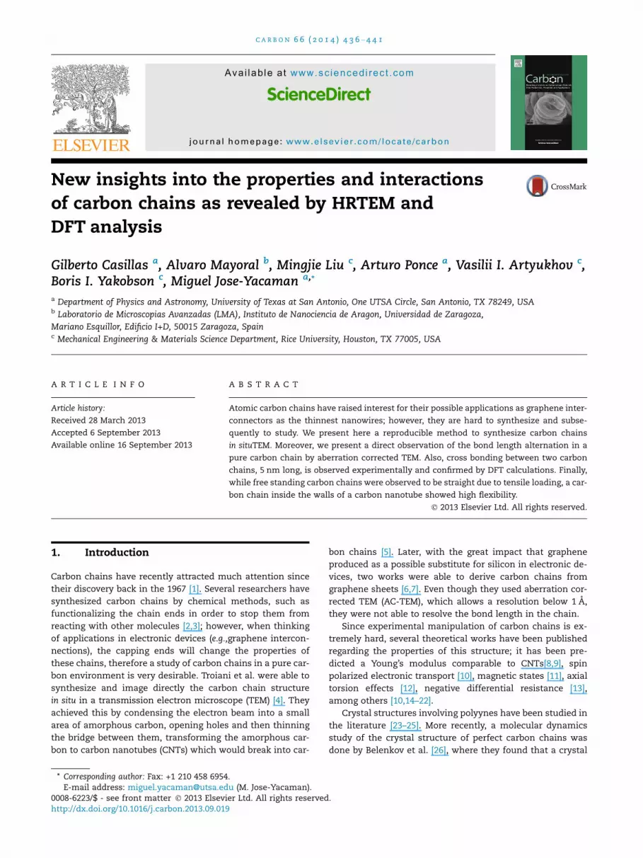
experiments. Fig. 1 shows a sequence of a typical in situ exper-
iment of the formation of the atomic carbon chains. Fig. 1a
shows an already formed chain inside a double wall CNT. As
the electron beam interacts with the multi walled CNTs
(MWCNTs), the inner CNT shell breaks and forms another
carbon chain (Fig. 1b–d), which breaks from one end and
forms a ring of carbon atoms (see Supplementary movie 1). Fi-
nally the outer CNT shell breaks forming a free standing
chain (Fig. 1f). Interestingly, in some experiments the last
CNT would break into two carbon chains bridging the open
ends of the CNT as shown in Fig. S2.
Fig. S3 shows six different chains that formed during the
experiments; the lengths of the formed chains varied from
1.3 nm to 2.24 nm in these cases (assuming a bond length of
0.14 nm, they would contain 9 and 16 C atoms). The percent-
age of successful formation of the chains was more than 80%
for a dose of 42 A/cm2. However, when a lower electron dose
was applied, 5 A/cm2, the ratio of success decreased to 10%,
obtaining smaller C chains (2 or 3 atoms). DFT calculations
by Marques et al. [35] showed that a CNTunder tension would
break into a chain if it has defects present, otherwise, it will
just break and close the open ends. In this sense, the energy
of the electrons plays an important role since the carbon
knock-on threshold is �80 kV[36]; therefore, using energies
of 200 and 300 kV, and at the same time using a high electron
beam dose, the probability of creating defects in the CNTs
(e.g., Stone–Wales, vacancies) increases leading to the forma-
tion of chains. This phenomenon may knock carbon atoms to
the vacuum; however, the thinning process is mainly due to
diffusion of the atoms away from the neck region, while the
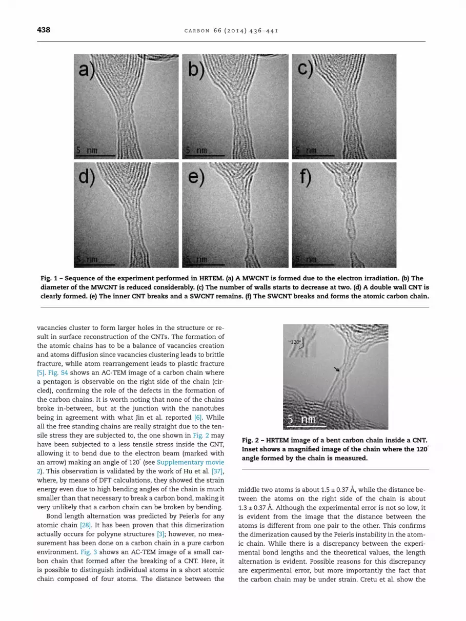
Fig. 1 – Sequence of the experiment performed in HRTEM. (a) A MWCNT is formed due to the electron irradiation. (b) The
diameter of the MWCNT is reduced considerably. (c) The number of walls starts to decrease at two. (d) A double wall CNT is
clearly formed. (e) The inner CNT breaks and a SWCNT remains. (f) The SWCNT breaks and forms the atomic carbon chain.
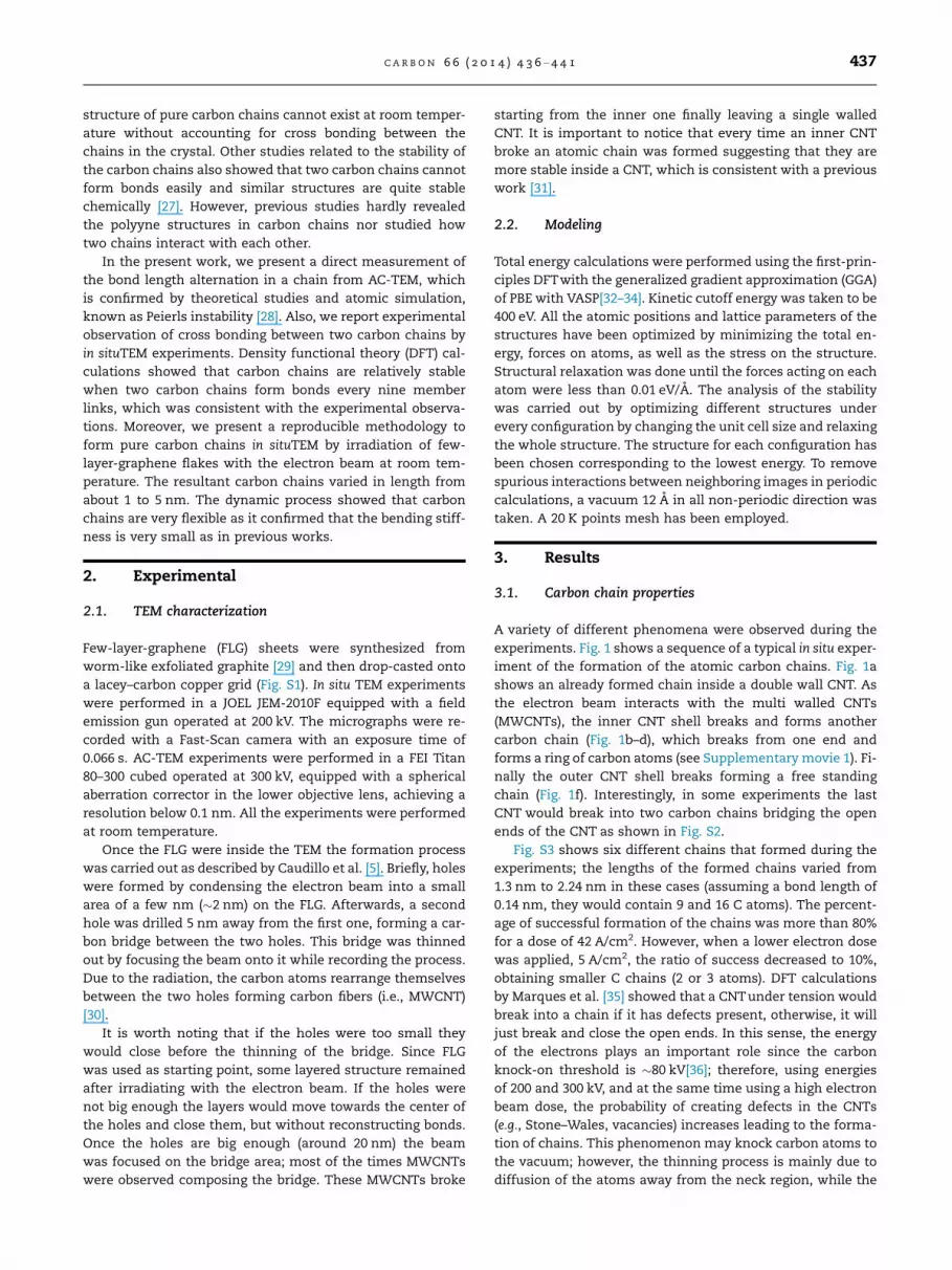
Fig. 2 – HRTEM image of a bent carbon chain inside a CNT.
Inset shows a magnified image of the chain where the 120�
angle formed by the chain is measured.
438 C A R B O N 6 6 ( 2 0 1 4 ) 4 3 6 – 4 4 1
vacancies cluster to form larger holes in the structure or re-
sult in surface reconstruction of the CNTs. The formation of
the atomic chains has to be a balance of vacancies creation
and atoms diffusion since vacancies clustering leads to brittle
fracture, while atom rearrangement leads to plastic fracture
[5]. Fig. S4 shows an AC-TEM image of a carbon chain where
a pentagon is observable on the right side of the chain (cir-
cled), confirming the role of the defects in the formation of
the carbon chains. It is worth noting that none of the chains
broke in-between, but at the junction with the nanotubes
being in agreement with what Jin et al. reported [6]. While
all the free standing chains are really straight due to the ten-
sile stress they are subjected to, the one shown in Fig. 2 may
have been subjected to a less tensile stress inside the CNT,
allowing it to bend due to the electron beam (marked with
an arrow) making an angle of 120� (see Supplementary movie
2). This observation is validated by the work of Hu et al. [37],
where, by means of DFT calculations, they showed the strain
energy even due to high bending angles of the chain is much
smaller than that necessary to break a carbon bond, making it
very unlikely that a carbon chain can be broken by bending.
Bond length alternation was predicted by Peierls for any
atomic chain [28]. It has been proven that this dimerization
actually occurs for polyyne structures [3]; however, no mea-
surement has been done on a carbon chain in a pure carbon
environment. Fig. 3 shows an AC-TEM image of a small car-
bon chain that formed after the breaking of a CNT. Here, it
is possible to distinguish individual atoms in a short atomic
chain composed of four atoms. The distance between the
middle two atoms is about 1.5 ± 0.37 A, while the distance be-
tween the atoms on the right side of the chain is about
1.3 ± 0.37 A. Although the experimental error is not so low, it
is evident from the image that the distance between the
atoms is different from one pair to the other. This confirms
the dimerization caused by the Peierls instability in the atom-
ic chain. While there is a discrepancy between the experi-
mental bond lengths and the theoretical values, the length
alternation is evident. Possible reasons for this discrepancy
are experimental error, but more importantly the fact that
the carbon chain may be under strain. Cretu et al. show the
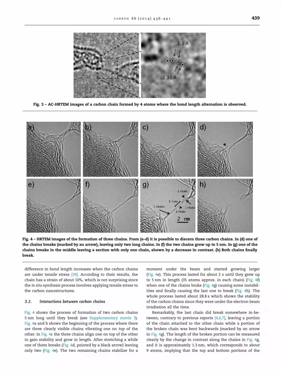
Fig. 4 – HRTEM images of the formation of three chains. From (a–d) it is possible to discern three carbon chains. In (d) one of
the chains breaks (marked by an arrow), leaving only two long chains. In (f) the two chains grow up to 5 nm. In (g) one of the
chains breaks in the middle leaving a section with only one chain, shown by a decrease in contrast. (h) Both chains finally
break.
Fig. 3 – AC-HRTEM images of a carbon chain formed by 4 atoms where the bond length alternation is observed.
C A R B O N 6 6 ( 2 0 1 4 ) 4 3 6 – 4 4 1 439
difference in bond length increases when the carbon chains
are under tensile stress [39]. According to their results, the
chain has a strain of about 10%, which is not surprising since
the in situ synthesis process involves applying tensile stress to
the carbon nanostructures.
3.2. Interactions between carbon chains
Fig. 4 shows the process of formation of two carbon chains
5 nm long until they break (see Supplementary movie 3).
Fig. 4a and b shows the beginning of the process where there
are three clearly visible chains vibrating one on top of the
other. In Fig. 4c the three chains align one on top of the other
to gain stability and grow in length. After stretching a while
one of them breaks (Fig. 4d, pointed by a black arrow) leaving
only two (Fig. 4e). The two remaining chains stabilize for a
moment under the beam and started growing larger
(Fig. 4e). This process lasted for about 2 s until they grew up
to 5 nm in length (35 atoms approx. in each chain) (Fig. 4f)
when one of the chains broke (Fig. 4g) causing some instabil-
ities and finally causing the last one to break (Fig. 4h). The
whole process lasted about 28.8 s which shows the stability
of the carbon chains since they were under the electron beam
irradiation all the time.
Remarkably, the last chain did break somewhere in-be-
tween, contrary to previous reports [4,6,7], leaving a portion
of the chain attached to the other chain while a portion of
the broken chain was bent backwards (marked by an arrow
in Fig. 4g). The length of the broken portion can be measured
clearly by the change in contrast along the chains in Fig. 4g,
and it is approximately 1.3 nm, which corresponds to about
9 atoms, implying that the top and bottom portions of the
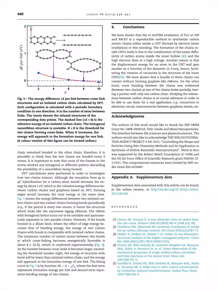
Fig. 5 – The energy difference DE per link between cross-link
structures and an isolated carbon chain calculated by DFT.
Each configuration is calculated with a periodic boundary
condition in one direction. N is the number of atom between
links. The insets denote the relaxed structures of the
corresponding data points. The dashed line (DE = 0) is the
reference energy of an isolated carbon chain. The hexagonal
nanoribbon structure is unstable. N = 8 is the threshold for
two chains forming cross-links. When N increases, the
energy will approach to the formation energy for one link.
(A colour version of this figure can be viewed online.)
440 C A R B O N 6 6 ( 2 0 1 4 ) 4 3 6 – 4 4 1
chain remained bonded to the other chain; therefore, it is
plausible to think that the two chains are bonded every 9
atoms. It is important to note that none of the frames in the
movie showed any hexagonal or different pattern discarding
the possibility of a nanoribbon being formed.
DFT calculations were performed in order to investigate
how two chains interact. Although the transition from sp to
sp2 hybridization for a carbon atom would decrease the en-
ergy by about 1 eV, which is the cohesive energy difference be-
tween carbon chains and graphene based on DFT, forming
edges would increase the total energy at the same time.
Fig. 5 shows the energy differences between two isolated car-
bon chains and two carbon chains forming bonds periodically
(e.g., if the period is every two atoms, it forms the structure
which looks like the narrowest zigzag ribbons). The ribbon
with hexagonal lattice turns out to be unstable and spontane-
ously separates in two parallel chains. However, if the bonds
formed in a dilute limit, where the effect of edge energy be-
comes that of bending energy, the energy of two carbon
chains with bonds is comparable with isolated carbon chains.
The minimum number of carbon atoms between two bonds
at which cross-linking becomes energetically favorable is
about 8 (�10 A), which is confirmed experimentally (Fig. 4).
As the number between cross-links N becomes larger, exceed-
ing the threshold number eight, the energy of structure with
bond will be lower than isolated carbon chain; and the energy
will approach to the formation energy of one link. The fitting
curve in Fig. 5 is by function DE ¼ Aþ BðN�CÞ where the first term
represents formation energy per link and second term repre-
sents bending energy of two chains.
4. Conclusions
We have shown that the in situTEM irradiation of FLG at 200
and 300 kV is a reproducible method to synthesize carbon
atomic chains either inside a CNT (formed by electron beam
irradiation) or free standing. The formation of the chains in-
side CNTs walls is due to the combination of the easier diffu-
sivity of carbon atoms inside the inner hollow [40] and the
high electron dose at a high voltage. Another reason is that
the displacement energy for an atom in the CNT wall gets
smaller as a function of the diameter (1–3 nm), hence, facili-
tating the creation of vacancies in the structure of the inner
CNTs[36]. We have shown that a bundle of three chains can
coexist without forming graphite-like ribbons. On the other
hand, cross bonding between the chains was evidenced
(between two chains) as one of the chains broke partially, leav-
ing a portion with only one carbon chain. Studying the interac-
tions between carbon chains is of crucial relevance in order to
be able to use them for a real application, e.g., connectors in
electronic circuit, interconnector between graphene sheets, etc.
Acknowledgments
The authors of this work would like to thank the NSF PREM
Grant No. DMR-0934218, Title: Oxide and Metal Nanoparticles.
The Interface between life sciences and physical sciences. The
authors would also like to acknowledge THE WELCH FOUNDA-
TION AGENCY PROJECT # AX-1615, ‘‘Controlling the Shape and
Particles Using Wet Chemistry Methods and Its Application to
Synthesis of Hollow Bimetallic Nanostructures’’. Work at Rice
was supported by the Robert Welch Foundation (C-1590) and
the US Air Force Office of Scientific Research grant FA9550-13-
1-0151. The computational resources were funded by NSF un-
der Grant EIA-0216467.
Appendix A. Supplementary data
Supplementary data associated with this article can be found,
in the online version, at http://dx.doi.org/10.1016/j.carbon.
2013.09.019.
R E F E R E N C E S
[1] Goresy AE, Donnay G. A new allotropic form of carbon fromthe ries crater. Science 1968;161(3839):363–4 [1968 July 26].
[2] Chalifoux WA, Tykwinski RR. Synthesis of polyynes to modelthe sp-carbon allotrope carbyne. Nat Chem 2010;2(11):967–71.
[3] Szafert S, Gladysz JA. Update 1 of: carbon in one dimension:structural analysis of the higher conjugated polyynes. ChemRev 2006;106(11):PR1–PR33 [2006/11/01].
[4] Troiani HE, Miki-Yoshida M, Camacho-Bragado GA, MarquesMAL, Rubio A, Ascencio JA, et al. Direct observation of themechanical properties of single-walled carbon nanotubesand their junctions at the atomic level. Nano Lett2003;3(6):751–5.
[5] Caudillo R, Troiani HE, Miki-Yoshida M, Marques MAL, RubioA, Yacaman MJ. A viable way to tailor carbon nanomaterialsby irradiation–induced transformations. Radiat Phys Chem2005;73(6):334–9.
C A R B O N 6 6 ( 2 0 1 4 ) 4 3 6 – 4 4 1 441
[6] Jin C, Lan H, Peng L, Suenaga K, Iijima S. Deriving carbonatomic chains from graphene. Phys Rev Lett2009;102(20):205501.
[7] Chuvilin A, Meyer JC, Algara-Siller G, Kaiser U. Fromgraphene constrictions to single carbon chains. New J Phys2009;11(8):083019.
[8] Castelli IE, Salvestrini P, Manini N. Mechanical properties ofcarbynes investigated by ab initio total-energy calculations.Phys Rev B 2012;85(21):214110.
[9] Nair AK, Cranford W, Buehler MJ. The minimal nanowire:mechanical properties of carbyne. Europhys Lett2011;95(1):16002.
[10] Zanolli Z, Onida G, Charlier JC. Quantum spin transport incarbon chains. ACS Nano 2010;4(9):5174–80.
[11] Xu B. Mechanical control of magnetic states of finite carbonchains encapsulated in single wall carbon nanotubes. ApplPhys Lett 2010;96(16):163105.
[12] Ravagnan L, Manini N, Cinquanta E, Onida G, Sangalli D,Motta C, et al. Effect of axial torsion on sp carbon atomicwires. Phys Rev Lett 2009;102(24):245502.
[13] Khoo KH, Neaton JB, Son YW, Cohen ML, Louie SG. Negativedifferential resistance in carbon atomic wire–carbonnanotube junctions. Nano Lett 2008;8(9):2900–5.
[14] Topsakal M, Ciraci S. Elastic and plastic deformation ofgraphene, silicene, and boron nitride honeycombnanoribbons under uniaxial tension: a first-principlesdensity-functional theory study. Phys Rev B2010;81(2):024107.
[15] Van Wesep RG, Chen H, Zhu W, Zhang Z. Communication:stable carbon nanoarches in the initial stages of epitaxialgrowth of graphene on Cu(111). J Chem Phys2011;134(17):171105.
[16] Erdogan E, Popov I, Rocha CG, Cuniberti G, Roche S, Seifert G.Engineering carbon chains from mechanically stretchedgraphene-based materials. Phys Rev B 2011;83(4):041401.
[17] Ataca C, Ciraci S. Perpendicular growth of carbon chains ongraphene from first-principles. Phys Rev B 2011;83(23):235417.
[18] dos Santos RB, Rivelino R, Mota FdB, Gueorguiev GK. Effectsof N doping on the electronic properties of a small carbonatomic chain with distinct sp^{2} terminations: a first-principles study. Phys Rev B 2011;84(7):075417.
[19] Hobi Jr E, Pontes RB, Fazzio A, da Silva AJR. Formation ofatomic carbon chains from graphene nanoribbons. Phys RevB 2010;81(20):201406.
[20] Lin ZZ, Ning J. Controlling the electronic properties ofmonoatomic carbon chains. Europhys Lett 2011;95(4):47012.
[21] Shen L, Zeng M, Yang S-W, Zhang C, Wang X, Feng Y. Electrontransport properties of atomic carbon nanowires betweengraphene electrodes. J Am Chem Soc 2010;132(33):11481–6[2010/08/25].
[22] Zeng MG, Shen L, Cai YQ, Sha ZD, Feng YP. Perfect spin-filterand spin-valve in carbon atomic chains. Appl Phys Lett2010;96(4):042104.
[23] Mohr W, Stahl J, Hampel F, Gladysz JA. Bent and stretched butnot yet to the breaking point: C8–C16 sp carbon chains thatspan two platinum atoms and the first structurallycharacterized 1,3,5,7,9,11,13,15-Octayne. Inorg Chem2001;40(14):3263–4 [2001/07/01].
[24] Sorokin PB, Lee H, Antipina LY, Singh AK, Yakobson BI.Calcium-decorated carbyne networks as hydrogen storagemedia. Nano Lett 2011;11(7):2660–5 [2011/07/13].
[25] Eisler S, Slepkov AD, Elliott E, Luu T, McDonald R, HegmannFA, et al. Polyynes as a model for carbyne: synthesis,physical properties, and nonlinear optical response. J AmChem Soc 2005;127(8):2666–76 [2005/03/01].
[26] Belenkov E, Mavrinsky V. Crystal structure of a perfectcarbyne. Crystallgraph Rep 2008;53(1):83–7.
[27] Casari CS, Li Bassi A, Ravagnan L, Siviero F, Lenardi C, Piseri P,et al. Chemical and thermal stability of carbyne-likestructures in cluster-assembled carbon films. Phys Rev B2004;69(7):075422.
[28] Kennedy T, Lieb EH. Proof of the peierls instability in onedimension. Phys Rev Lett 1987;59(12):1309–12.
[29] Gu W, Zhang W, Li X, Zhu H, Wei J, Li Z, et al. Graphenesheets from worm-like exfoliated graphite. J Mater Chem2009;19(21):3367–9.
[30] Banhart F. Irradiation effects in carbon nanostructures. RepProg Phys 1999;62(8):1181.
[31] Wang Z, Ke X, Zhu Z, Zhang F, Ruan M, Yang J. Carbon-atomchain formation in the core of nanotubes. Phys Rev B2000;61(4):R2472.
[32] Kresse G, Hafner J. Ab initio molecular dynamics for liquidmetals. Phys Rev B 1993;47(1):558–61.
[33] Kresse G, Furthmuller J. Efficient iterative schemes forab initio total-energy calculations using a plane-wave basisset. Phys Rev B 1996;54(16):11169–86.
[34] Perdew JP, Burke K, Ernzerhof M. Generalized gradientapproximation made simple. Phys Rev Lett1996;77(18):3865–8.
[35] Marques MAL, Troiani HE, Miki-Yoshida M, Jose-Yacaman M,Rubio A. On the breaking of carbon nanotubes under tension.Nano Lett 2004;4(5):811–5.
[36] Krasheninnikov AV, Banhart F, Li JX, Foster AS, NieminenRM. Stability of carbon nanotubes under electronirradiation: role of tube diameter and chirality. Phys Rev B2005;72(12):125428.
[37] Hu YH. Bending effect of sp-Hybridized carbon (Carbyne)chains on their structures and properties. J Phys Chem C2011;115(5):1843–50 [2011/02/10].
[38] Cretu O, Botello-Mendez AR, Janowska I, Pham-Huu C,Charlier JC, Banhart F. Electrical conductivity measured inatomic carbon chains. Nano Lett 2013;13(8):3487–93.
[40] Krasheninnikov AV, Nordlund K, Lehtinen PO, Foster AS,Ayuela A, Nieminen RM. Adsorption and migration of carbonadatoms on carbon nanotubes: density-functional ab initioand tight-binding studies. Phys Rev B 2004;69(7):073402.