NEPLAN-Simpow Integration STRI and BCP have agreed to integrate the Simpow dynamic and linear analysis modules in the NEPLAN planning and optimization software.
NEPLAN users will now profit from one of the best dynamic analysis package, including transient stability, EMT simulation and linear analysis with most advanced dynamic models. Over 25 years development experiences are included in the Simpow package.
This integration improves further the transmission system module in the NEPLAN power system analysis software.
The new integrated versions of Simpow and NEPLAN will be available in July 2005.
The combined package will be one of the most complete power system planning and optimization tool on the market.
STRI and BCP will also collaborate within support, marketing and sales of their respective software. For further information, please contact STRI or BCP. Special features included in Simpow are:
• EMT (instantaneous value mode) and RMS (fundamental frequency mode) simulation.
• Enhanced Linear Analysis module with RMS and EMT models. • Many field proven dynamic models. • Robust numerical technique characterized by accuracy with variable and fixed
time step. • To insure correct and fast results from the integration algorithm, the “backward
differentiation method” is used for stiff integration variables and the “trapezoidal method” is used for non-stiff integration variables.
• Calculation of Fast Fourier Transformation (FFT). • Enhanced dynamic synchronous machine models, including an advanced
model for machine start-up simulations in EMT mode. • Enhanced dynamic asynchronous machine models. • Enhanced HVDC and the corresponding HVDC controller models. • Enhanced dynamic FACTS models. • Switching between fundamental frequency mode (RMS) and instantaneous
value mode (EMT), just before an interesting point of time occurs. • Part of the network can be modeled in fundamental frequency mode (RMS)
and on other part in instantaneous value mode (EMT). This feature is probably unique on the market.
• The high level dynamic simulation language (DSL) allows not only to model user defined regulators but also primary components like synchronous machines, FACTS etc.

Single line diagram of an HVDC system Dialog for the predefined HVDC controllers
VVIK02VVIKP=139.673 MWQ=41.935 Mvar
I=0.548 kAPloss=3.601 MW
Qloss=35.559 Mvar
T1Tap=0
T2Tap=0
ShuntP=0.000 MW
GVVIKP=-139.673 MWQ=-41.935 Mvar
VVIK0135 kV
u=113.85 %Uang=0.00 °
G14P=0.895 MW
Q=-18.922 MvarG12
P=0.000 MWQ=-15.000 Mvar
P=-135.168 MWQ=0.000 Mvar
I=0.900 kAPloss=0.903 MW
Qloss=64.846 Mvar
P=133.143 MWQ=0.000 Mvar
I=0.900 kAPloss=0.903 MW
Qloss=47.863 Mvar
DCLine1P=135.168 MW
I=0.900 kAPloss=1.013 MW
DCLine2P=134.155 MW
I=0.900 kAPloss=1.012 MW
P=0.000 MWQ=15.000 Mvar
I=0.684 kAPloss=0.015 MW
Qloss=0.308 Mvar
P=0.015 MWQ=-14.692 Mvar
I=0.113 kAPloss=0.015 MW
Qloss=0.308 Mvar
P=-0.895 MWQ=18.922 Mvar
I=0.773 kAPloss=0.024 MW
Qloss=0.486 Mvar
NG1415.2 kV
u=93.14 %Uang=0.00 °
P=0.919 MWQ=-18.435 Mvar
I=0.142 kAPloss=0.024 MW
Qloss=0.486 Mvar
NG1213.8 kV
u=91.70 %Uang=0.09 °
LoadYP=131.304 MWQ=0.000 Mvar
VVIK1P=0.000 MW
Q=-37.437 Mvar
VVIK2P=0.000 MW
Q=-39.925 Mvar
YGNE1P=0.000 MW
Q=-15.488 Mvar
YGNE2P=0.000 MW
Q=-18.086 Mvar
CFC_VVIK CCA_VVIK CFC_YGNE CCA_YGNEMC_VVIKCOL_VVIK COL_YGNE
WikFir.=24.26 degRatio=0.000
Cntrl=
YngedFir.=145.35 degRatio=0.000
Cntrl=
GDC1150 kV
u=100.12 %
GDC2150 kV
u=99.37 %
DC-75898P=0.001 MW
Q=0.000 Mvar DC-75911P=0.001 MW
Q=0.000 Mvar
P=-0.001 MWQ=0.000 Mvar
I=0.900 kAPloss=0.903 MW
Qloss=47.863 Mvar
TUR-33777
TUR-33781
Exiter-33776
TR2_YGNETap=1
P=-132.239 MWQ=66.701 Mvar
I=1.141 kAPloss=0.000 MW
Qloss=18.838 Mvar
YGNE75 kV
u=99.96 %Uang=0.15 °
P=132.239 MWQ=-47.863 Mvar
I=0.699 kAPloss=0.000 MW
Qloss=18.838 Mvar
P=136.072 MWQ=64.846 Mvar
I=0.700 kAPloss=0.903 MW
Qloss=64.846 Mvar
TR2_VVIKTap=0
P=-132.239 MWQ=47.863 Mvar
I=0.699 kAPloss=0.903 MW
Qloss=47.863 Mvar
P=-136.072 MWQ=-64.846 Mvar
I=0.700 kAPloss=0.000 MW
Qloss=18.892 Mvar
VVG2AC123.9 kV
u=100.33 %Uang=-20.16 °
P=136.072 MWQ=83.738 Mvar
I=0.643 kAPloss=0.000 MW
Qloss=18.892 Mvar
VVIK135 kV
u=106.35 %Uang=-14.03 °
YGG2AC123.9 kV
u=93.74 %Uang=7.02 °
GDC_E2150 kV
u=0.00 %
GDC3150 kV
u=98.62 %
P=-0.001 MWQ=0.000 Mvar
I=0.900 kAPloss=0.903 MW
Qloss=64.846 Mvar
GDC_E1150 kV
u=-0.00 %
Gov-76506
Gov-795070
HVDC Control System
Turbine and Exiter
Rectifier Inverter
Rectifier Inverter
HVDC-Example designed by STRI (Sweden) and BCP (Switzerland)
Master
Turbine and Governor

Results of the above HVDC simulation Results of the displayed in the NEPLAN chart manager
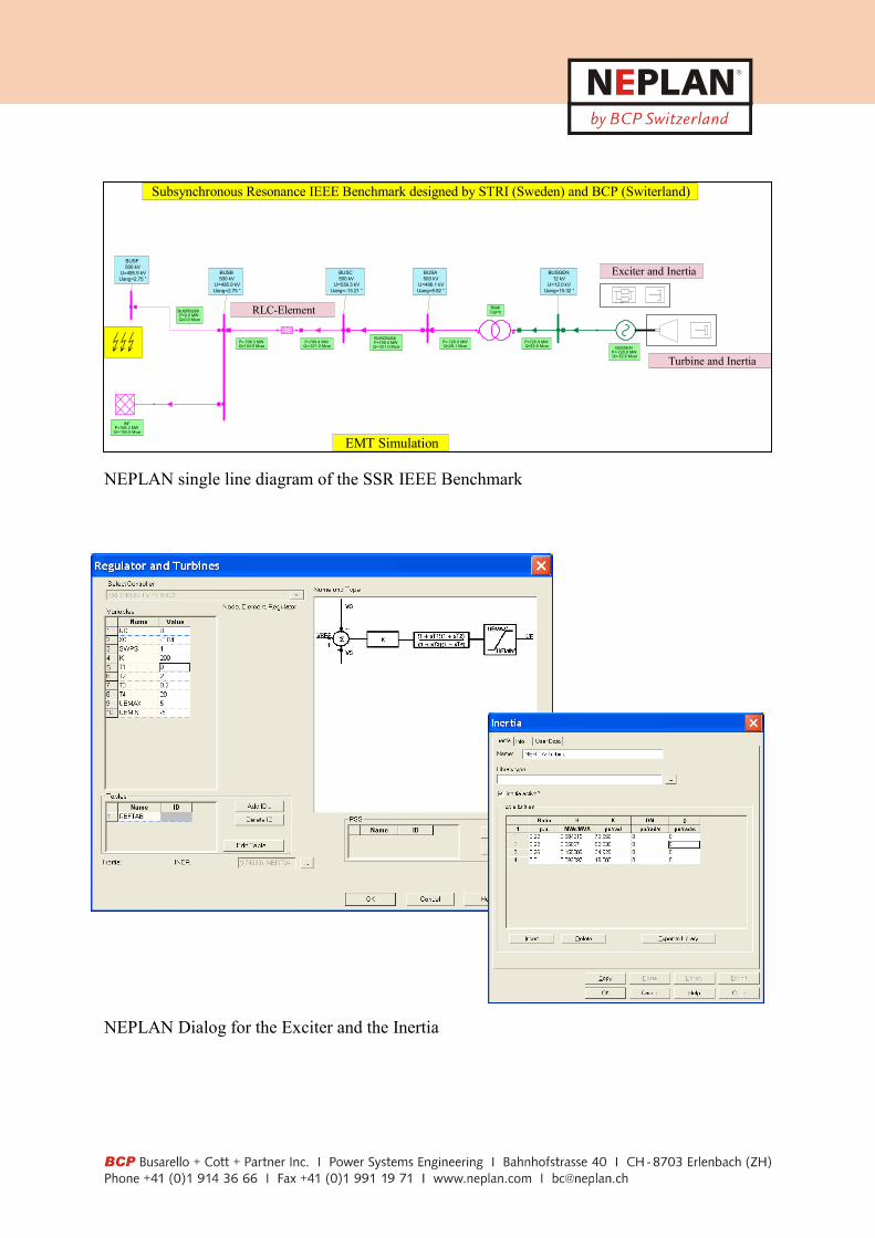
NEPLAN single line diagram of the SSR IEEE Benchmark NEPLAN Dialog for the Exciter and the Inertia
BUSGENP=-720.0 MWQ=-52.6 Mvar
TRAFTap=0
BUSCBUSAP=709.4 MWQ=-321.0 Mvar
RLC
P=709.4 MWQ=-321.0 Mvar
BUSC500 kV
U=539.3 kVUang=-13.21 °
BUSFBUSBP=0.0 MWQ=0.0 Mvar
BUSF500 kV
U=495.9 kVUang=2.75 °
P=-708.3 MWQ=104.5 Mvar
BUSGEN12 kV
U=12.0 kVUang=15.32 °
P=720.0 MWQ=52.6 Mvar
BUSA500 kV
U=499.1 kVUang=8.82 °
P=-720.0 MWQ=29.1 Mvar
INFP=708.3 MW
Q=-104.5 Mvar
INERTIA-Turbine
INERTIA-ExciterBUSB500 kV
U=495.9 kVUang=2.75 °
Subsynchronous Resonance IEEE Benchmark designed by STRI (Sweden) and BCP (Switerland)
EMT Simulation
Turbine and Inertia
Exciter and Inertia
RLC-Element

Results of SSR Benchmark of the Simpow EMT Simulation FFT (Fast Fourier Transformation) of the above SSR Result Curve

NEPLAN Block Diagram of an user defined Ex NEPLAN Dialog for the Simpow Simulat
IF(START.AND.(.NOT.START0).AND.IDC.EQ/0./.0.)THEN IF(DI.EQ/0./.0.)THEN UCR=UPRE(NODE1) UCI=UPIM(NODE1) UC=SQRT(UCR0**2+UCI0**2) UDIO0=FACY*UC FAC=(U(NODE2)-U(NODE3))/UDIO0 IF(1.-FAC*FAC.LE.0.)THEN FAC1=0. ELSE
citer and Simpow DSL Language
ion Parameters

NEPLAN single line diagram of a FACTS (UPFC) example with PWM and Series Transformer NEPLAN Dialog of a PWM and standard Simpow PWM-Controller
UPFC
Tap=-9
P=-10.504Q=123.871
P=12.386Q=0.000 P=12.428
Q=-8.086P=-12.396Q=0.000
P=157.907Q=32.757
P=-154.949Q=-129.265
P=300.000Q=150.000
P=-613.328Q=-20.905
P=0.010
NDCVSC10 kV
u=100.00
P=160.122Q=-80.320
P=-157.907Q=-32.757
NAC12345 kV
u=101.95
P=151.248Q=-68.357
P=-149.286Q=-45.761
P=147.299Q=-70.659
P=-145.051Q=-20.735
NAC2345 kVu=93.55
P=11.758Q=-111.388
P=-300.000Q=-150.000
P=301.958Q=169.582
NAC1345 kV
u=101.45
P=300.000Q=150.000
NAC10345 kVu=98.25
P=-11.758Q=111.388
NACVSC18 kV
u=100.00
Tap=0User=28.495
Phi_ser=-11.49
P=159.790Q=-78.110
NAC31345 kV
u=101.00
P=-147.299Q=70.659
NAC32345 kVu=92.77
P=-12.428Q=8.086
NACVSC28 kV
u=82.99
UPFC-Example designed by STRI (Sweden) and BCP (Switzerland)
PWM-Controller PWM-Controller

Switching between RMS and EMT Simulation Only RMS-Simulation
Only EMT-Simulation Switching between RMS and EMT after 1.0s and back again to RMS after 1.5s I f you need more information about the NEPLAN-Simpow interface please contact: Giatgen Cott BCP Busarello + Cott+ Partner AG E-Mail: [email protected]