Doc No: NR-NRCSD-S0003
Revision: -
NANORACKS PROPRIETARY RIGHTS ARE INCLUDED HEREIN. RECIPIENT AGREES THAT NEITHER THIS DOCUMENT NOR THE INFORMATION DISCUSSED HEREIN NOR ANY PART THEREOF SHALL BE REPRODUCED OR DISCLOSED TO OTHERS.
NanoRacks CubeSat Deployer (NRCSD) Interface Definition Document (IDD)
NRCSD

NanoRacks CubeSat Deployer IDD NRCSD Doc No: NR-NRCSD-S0003 Rev: -
NanoRacks CubeSat Deployer (NRCSD)
Interface Definition Document (IDD)
NRCSD
Prepared by
Tristan Prejean; Mission Manager; Date
Reviewed by
Henry Martin; Senior Mission Manager; Date
Reviewed by
Conor Brown; External Payloads Manager; Date
Reviewed by
Troy Guy; Electrical Engineer; Date
Reviewed by
Teresa Freund; Safety Engineer; Date
Approved by
Mike Lewis; Chief Technology Officer; Date

NanoRacks CubeSat Deployer IDD NRCSD Doc No: NR-NRCSD-S0003 Rev: -
List of Revisions
Revision Revision Date Revised By Revision Description
- 5/29/2018 Tristan Prejean Initial Release

NanoRacks CubeSat Deployer IDD NRCSD Doc No: NR-NRCSD-S0003 Rev: -
Table of Contents
1 Introduction 6 1.1 Purpose 6 1.2 Scope 6 1.3 Usage 6 1.4 Exceptions 6
2 Acronyms, Definitions, and Applicable Documents 7
3 NanoRacks CubeSat Deployer System Overview 10 3.1 NRCSD Overview and Payload Capacity 10 3.2 NRCSD Coordinate System 10 3.3 NRCSD Design Features 11 3.4 NRCSD Operations Overview 12
3.4.1 Schedule 12 3.4.2 Ground Operations 13 3.4.3 On-Orbit Environments, Interfaces, and Operations 15
4 Payload Interface Requirements 21 4.1 Structural and Mechanical Systems Interface Requirements 21
4.1.1 CubeSat Mechanical Specification 21 4.1.2 CubeSat Mass Properties 24 4.1.3 RBF / ABF Access 24 4.1.4 Deployment Switches 25 4.1.5 Deployable Systems and Integration Constraints 25 4.1.6 Deployment Velocity and Tip-Off Rate Compatibility 25
4.2 Electrical System Interface Requirements 26 4.2.1 Electrical System Design and Inhibits 26 4.2.2 Electrical System Interfaces 27
4.3 Environmental Interface Requirements 28 4.3.1 Acceleration Loads 28 4.3.2 Random Vibration Environment 28 4.3.3 Launch Shock Environment 30 4.3.4 On-Orbit Acceleration 31 4.3.5 Integrated Loads Environment 31 4.3.6 Thermal Environment 32 4.3.7 Humidity 32 4.3.8 Airlock Depressurization 33
4.4 Safety Requirements 33 4.4.1 Containment of Frangible Materials 35 4.4.2 Venting 35 4.4.3 Secondary Locking Feature 36 4.4.4 Passivity 36 4.4.5 Pyrotechnics 36 4.4.6 Space Debris Compliance 36 4.4.7 Batteries 37 4.4.8 Pressure Vessels 41 4.4.9 Propulsion System 41

NanoRacks CubeSat Deployer IDD NRCSD Doc No: NR-NRCSD-S0003 Rev: -
4.4.10 Materials 42 4.4.11 Electrical Bonding 42
4.5 Jettison Requirements 42 4.5.1 CubeSats with Propulsion 43 4.5.2 Re-entry Survivability 43
4.6 Documentation Requirements 43 4.6.1 Regulatory Compliance 43 4.6.2 Documentation 44
5 Requirements Matrix 45
List of Tables and Figures Table 2-1: Acronyms ................................................................................................................. 7 Table 2-2: Applicable Documents ............................................................................................ 9 Figure 3.1-1: NanoRacks CubeSat Deployer (NRCSD) ............................................................ 10 Figure 3.2-1: NRCSD Coordinate System ................................................................................ 10 Figure 3.3-1: NanoRacks CubeSat Deployer Design Features ................................................ 11 Table 3.4.1-1: Template Milestone Schedule......................................................................... 12 Figure 3.4-1: Sample NRCSD Stowage Configuration for Launch (NRCSD Quad-Pack in M2 CTB)
............................................................................................................................. 15 Table 3.4.3.2-1: ISS Internal Environmental Conditions (Ref SSP 57000) .............................. 16 Figure 3.4.3.2-2: Operating Limits of the ISS Atmospheric Total Pressure, and Nitrogen and
Oxygen Partial Pressures (Ref SSP 57000) ........................................................... 17 Figure 3.4.3.3-1: NRCSD Standard and DoubleWide on MPEP .............................................. 18 Figure 3.4.3.4-1: JEM Airlock Slide Table ............................................................................... 20 Figure 3.4.3.4-2: JEM Overview.............................................................................................. 20 Figure 3.4.3.4-3: NRCSD Deployment of Three (3) CubeSats from ISS (Photo Credit: NASA) 20 Figure 4.1.1-1: NRCSD Mechanical Interface (Dimensions in mm) ........................................ 22 Figure 4.1.1-2: NRCSD Payload Envelope Specification (Dimensions in mm) ........................ 23 Table 4.1.2-1: CubeSat Mass Limits ....................................................................................... 24 Figure 4.2.1-1: CubeSat Electrical Subsystem Block Diagram (Note: RBF pins not shown) ... 27 Table 4.3.1-1: Launch Load Factors Envelope ........................................................................ 28 Figure 4.3.2.1-1: Random Vibration Test Profiles .................................................................. 29 Table 4.3.2.1-1: Random Vibration Test Profiles ................................................................... 30 Table 4.3.4-1: On-Orbit Acceleration Environment ............................................................... 31 Table 4.3.6-1: Expected Thermal Environments .................................................................... 32 Table 4.6.2-1: Data Deliverables ............................................................................................ 44 Table 5-1: NanoRacks CubeSat Deployer Requirements Matrix ............................................ 45

NanoRacks CubeSat Deployer IDD NRCSD Doc No: NR-NRCSD-S0003 Rev: -
6
1 Introduction
1.1 Purpose This Interface Definition Document (IDD) provides the minimum requirement set to verify compatibility of a small satellite with the NanoRacks CubeSat Deployer system (NRCSD). This IDD includes all applicable International Space Station (ISS) flight safety and interface requirements for payload use of the NRCSD. NanoRacks verifies compliance to all applicable requirements directly to the ISS Program on behalf of the Payload Developer (PD) based on incremental data requests.
1.2 Scope This IDD is the sole requirements document for end users of the NRCSD (the PD or the Customer). The physical, functional, and environmental design requirements associated with payload safety and interface compatibility for flight with the NRCSD are included herein. The requirements defined in this document apply to all phases of the mission leading up to the deployment of the payload from the ISS, including both the pressurized and unpressurized operations on ISS. In some circumstances, the design requirements outlined in this document may also govern the operational, post-deployment mission phase of the payload. The interface requirements defined herein primarily address the Payload to NRCSD interface, but also include requirements derived from ISS Program safety documentation and interface control agreements with the Japan Aerospace Exploration Agency (JAXA).
1.3 Usage This document levies design interface and verification requirements on payload developers (i.e. NRCSD satellite customers). These requirements are allocated to a payload through the unique payload Interface Control Agreement (ICA). The unique payload ICA documents the payload compliance with the requirements defined in this IDD. The ICA is utilized as the documentation tool to capture requirements verification approaches, data submittals, schedule updates, and any required exceptions.
1.4 Exceptions Exception is the general term used to identify any payload developer-proposed departure from specified requirements or interfaces. Any exception to requirements, capabilities, or services defined in this IDD shall be documented in the ICA and evaluated to ensure that the stated condition is controlled and acceptable. The ICA will be revised throughout the payload design verification process and will document the specific requirement excepted, the exception number, the exception title, and the approval status.

NanoRacks CubeSat Deployer IDD NRCSD Doc No: NR-NRCSD-S0003 Rev: -
7
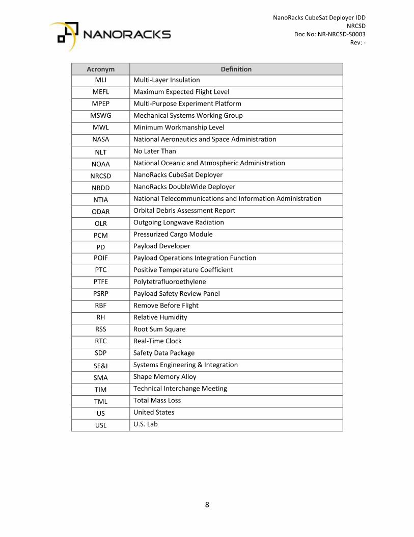
2 Acronyms, Definitions, and Applicable Documents
Table 2-1: Acronyms
Acronym Definition ASD Acceleration Spectral Density
BN Ballistic Number
BoM Bill of Materials
C&DH Command & Data Handling
CMC Cargo Mission Contract
CM Center of Mass
CoC Certificate of Compliance
COL Columbus Module
COTS Commercial Off-the-Shelf
CVCM Collected Volatile Condensable Material
CTB Cargo Transfer Bag
DFMR Designed for Minimum Risk
DOT Department of Transportation EF Exposed Facility
EPS Electrical Power System
ESD Electrostatic Discharge
ETFE Ethylene tetrafluoroethylene
EVR Extravehicular Robotics
FCC Federal Communications Commission
FOD Foreign Object Debris
GSE Ground Support Equipment
HFIT Human Factors Implementation Team
ICA Interface Control Agreement
IDD Interface Definition Document
I/F Interface
ISS International Space Station
ITU International Telecommunication Union
JEM Japanese Experiment Module
JEMRMS Japanese Experiment Module Remote Manipulator System
JSC Johnson Space Center
LCM Launch Command Multiplexer
NanoRacks CubeSat Deployer IDD NRCSD Doc No: NR-NRCSD-S0003 Rev: -
8
Acronym Definition MLI Multi-Layer Insulation
MEFL Maximum Expected Flight Level MPEP Multi-Purpose Experiment Platform
MSWG Mechanical Systems Working Group
MWL Minimum Workmanship Level
NASA National Aeronautics and Space Administration
NLT No Later Than
NOAA National Oceanic and Atmospheric Administration
NRCSD NanoRacks CubeSat Deployer
NRDD NanoRacks DoubleWide Deployer
NTIA National Telecommunications and Information Administration
ODAR Orbital Debris Assessment Report
OLR Outgoing Longwave Radiation
PCM Pressurized Cargo Module
PD Payload Developer
POIF Payload Operations Integration Function
PTC Positive Temperature Coefficient
PTFE Polytetrafluoroethylene
PSRP Payload Safety Review Panel
RBF Remove Before Flight RH Relative Humidity
RSS Root Sum Square
RTC Real-Time Clock
SDP Safety Data Package
SE&I Systems Engineering & Integration
SMA Shape Memory Alloy
TIM Technical Interchange Meeting
TML Total Mass Loss
US United States
USL U.S. Lab
NanoRacks CubeSat Deployer IDD NRCSD Doc No: NR-NRCSD-S0003 Rev: -
9
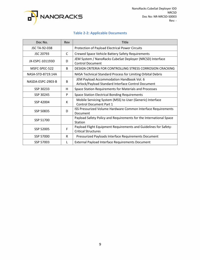
Table 2-2: Applicable Documents
Doc No. Rev Title
JSC TA-92-038 Protection of Payload Electrical Power Circuits
JSC 20793 C Crewed Space Vehicle Battery Safety Requirements
JX-ESPC-101193D D JEM System / NanoRacks CubeSat Deployer (NRCSD) Interface Control Document
MSFC-SPEC-522 B DESIGN CRITERIA FOR CONTROLLING STRESS CORROSION CRACKING
NASA-STD-8719.14A NASA Technical Standard Process for Limiting Orbital Debris
NASDA-ESPC-2903-B B JEM Payload Accommodation Handbook Vol. 6 Airlock/Payload Standard Interface Control Document
SSP 30233 H Space Station Requirements for Materials and Processes
SSP 30245 P Space Station Electrical Bonding Requirements
SSP 42004 K Mobile Servicing System (MSS) to User (Generic) Interface Control Document Part 1
SSP 50835 D ISS Pressurized Volume Hardware Common Interface Requirements Document
SSP 51700 Payload Safety Policy and Requirements for the International Space Station
SSP 52005 F Payload Flight Equipment Requirements and Guidelines for Safety-Critical Structures
SSP 57000 R Pressurized Payloads Interface Requirements Document
SSP 57003 L External Payload Interface Requirements Document

NanoRacks CubeSat Deployer IDD NRCSD Doc No: NR-NRCSD-S0003 Rev: -
10
3 NanoRacks CubeSat Deployer System Overview
This section is an overview of the NanoRacks CubeSat Deployer (NRCSD) system and describes the various system interfaces and the operational elements of the payload lifecycle. The payload interface requirements are captured in Section 4.
3.1 NRCSD Overview and Payload Capacity The NRCSD (see Figure 3.1-1) is a self-contained CubeSat deployer system for small satellites staged from the International Space Station (ISS). The NRCSD launches inside the Pressurized Cargo Module (PCM) of ISS cargo resupply vehicles and utilizes the ISS Japanese Experiment Module (JEM) as a staging facility for operation. The NRCSD is integrated with payloads on the ground at a NanoRacks facility prior to flight and mechanically and electrically isolates CubeSats from the cargo resupply vehicles, ISS, and ISS crew.
Figure 3.1-1: NanoRacks CubeSat Deployer (NRCSD)
The NRCSD is designed to accommodate any combination of 1U, 2U, 3U, 4U, or 5U CubeSats up to a maximum volume of 6U, or a single 6U CubeSat in the 1x6x1U configuration. The standard payload form factors and dimensional requirements are detailed in Section 4.
3.2 NRCSD Coordinate System The NRCSD coordinate system is defined in Figure 3.2-1 (location of origin not considered).
Figure 3.2-1: NRCSD Coordinate System

NanoRacks CubeSat Deployer IDD NRCSD Doc No: NR-NRCSD-S0003 Rev: -
11
3.3 NRCSD Design Features The NRCSD is a rectangular ‘silo’ that consists of four (4) sidewalls, a base plate, a pusher plate assembly with ejection spring, two (2) access panels, two (2) doors, and a primary release mechanism (see Figure 3.3-1). The deployer doors are located on the forward end (+Z face), the base plate assembly is located on the aft end (-Z face), and the access panels are on one side of the dispenser (+ Y face). The inside walls of the NRCSD are smooth bore design to minimize and/or preclude hang-up or jamming of CubeSat appendages during deployment should these become released prematurely.
The release mechanism is a commercial off-the-shelf (COTS) mechanism with redundant channels; this component has an extensive space heritage. The integrated door design was completed by NanoRacks and has been designated ‘DFMR’, or Designed For Minimum Risk, by the Mechanical Systems Working Group (MSWG) at the Johnson Space Center (JSC).
Figure 3.3-1: NanoRacks CubeSat Deployer Design Features

NanoRacks CubeSat Deployer IDD NRCSD Doc No: NR-NRCSD-S0003 Rev: -
12
The NRCSD has a thumb screw that secures the NRCSD doors for flight. The thumb screw ensures that the primary release mechanism does not experience excess loading during the ground handling and ascent / launch portion of the mission. The NRCSD also has a jack screw and jam nut assembly that allows the integrated payload subsystem to be preloaded / secured in the Z axis for flight. The jack screw and jam nut assembly are installed on the deployer base plate. The thumb screw, jack screw, and jam nut are removed by the ISS crew prior to deployment operations. The NRCSD access panels are removed on the ground so that additional access is available during the payload fit-check and integration process. The access ports provide the only access for remove before flight (RBF) and / or apply before flight (ABF) features while the payloads are inside the NRCSD. The access panels are installed prior to handover for flight and are never opened on-orbit by the ISS crew.
3.4 NRCSD Operations Overview
3.4.1 Schedule
Table 3-1 is a template schedule outlining the major safety and hardware milestones for payload developers (PDs). The majority of the schedule milestones are related to the phased ISS safety review process with the Payload Safety Review Panel (PSRP) and the associated data milestones. The detailed payload schedule will be coordinated between NanoRacks and the payload developer and documented in the unique payload ICA.
Table 3.4.1-1: Template Milestone Schedule
Milestone/Activity Launch-minus Dates (Months)
Feasibility Study / Contract Signing L – 12
Regulatory Compliance Initiation by PD (Spectrum Coordination, Remote Sensing) L – 12
NanoRacks / PD Kickoff Meeting L-12
Interface Control Agreement (ICA) Initiation L-12
NanoRacks / PD Safety Data Call Initiation L-12
Baseline ICA L-11
Phase 0/I Support Data from PD Complete L-11
Phase 0/I Safety Data Package (SDP) Submittal to PSRP L-10
NanoRacks / ISS Program Kickoff Meeting L – 9.5
Phase 0/I Safety Review L – 9
Phase 2 Support Data from PD Complete L-8
Phase 2 SDP Submittal to PSRP L-7
Phase 2 Safety Review L-6

NanoRacks CubeSat Deployer IDD NRCSD Doc No: NR-NRCSD-S0003 Rev: -
13
Milestone/Activity Launch-minus Dates (Months)
ICA Signed by PD and NanoRacks L-6
NRCSD and CubeSat Fit-Check L-5
Payload Environmental Testing L-5
ISS Program Required Flight Acceptance Testing L-5
Phase 3 Support Data from PD Complete L-4.5
Phase 3 SDP Submittal to PSRP L-4
Phase 3 Safety Review L-3.5
Regulatory Licensing in Place L-3.5
Payload Delivery to NanoRacks L-1.5 to L-3.5
NanoRacks Cargo Handover to NASA L-1 to L-3
3.4.2 Ground Operations
3.4.2.1 Mechanical Fit-Check
NanoRacks will coordinate complete mechanical interface checks between the satellite and the NRCSD prior to final integration of the payload. Fit-checks are conducted with the hardware intended for flight. Use of flight-like engineering qualification hardware in lieu of flight models must be coordinated with NanoRacks and documented in the ICA.
3.4.2.2 Delivery to NanoRacks
The PD will deliver the complete payload to the NanoRacks Houston facility, or another facility as documented in the ICA, by the dates listed in the schedule for installation into the deployer. Any special requirements, such as ground support equipment (GSE), special handling instructions, cleanliness requirements, humidity requirements, ESD sensitivity, etc., shall be documented in the payload specific ICA.
3.4.2.3 NanoRacks Inspection
NanoRacks performs inspections of the payload to verify it meets the required safety and mechanical design requirements outlined in this IDD and the ICA. Typically, this includes, but is not limited to, mass properties and critical mechanical dimensions. This inspection takes place at the point of the fit-check and is repeated at the point that the payload is handed over to NanoRacks prior to final integration with the NRCSD. Note that any requirements that cannot be verified through inspection, measurements, and fit-check with the NRCSD must be verified via documentation and data submittals in advance of final payload delivery to NanoRacks.

NanoRacks CubeSat Deployer IDD NRCSD Doc No: NR-NRCSD-S0003 Rev: -
14
3.4.2.4 Payload Developer Ground Servicing
The PD may perform payload activities at the NanoRacks facilities prior to final installation into the deployer, based on the agreements in the ICA, as long as these activities are within the scope of the documented and verified payload design. These payload activities may include post-shipment functional tests, battery charging, etc. Typically, these activities are completed prior to installation of the payload into the NRCSD. Note that the only access to the payload after the installation is complete is via the NRCSD access panels on the + Y face of the dispenser. No material or design changes shall be implemented at this phase of the processing. Once the payload has been delivered for flight to the ISS Cargo Mission Contract (CMC) team, no further payload servicing is permitted. The time between payload handover to NanoRacks and transfer to CMC is nominally about 1 week. Any post-delivery payload activities besides standard post-shipment receive and inspect procedures must be coordinated in advance and documented in the payload specific ICA.
3.4.2.5 NanoRacks Data Gathering for On-Orbit Operations
NanoRacks will assess the payload to develop products and procedures in support of on-orbit operations and crew interaction. Typically, no crew interaction with the CubeSats is permitted. Any request for crew interaction with the payload, including imagery requests during the deployment, must be coordinated with NanoRacks and documented via the unique payload ICA.
3.4.2.6 NanoRacks Testing
Although not normally required for CubeSats, NanoRacks may perform testing of the CubeSat based on the agreements made in the unique payload ICA. This may include, but is not limited to, support of vibration tests utilizing NanoRacks GSE, final charging of the payloads, visual and mechanical inspections, etc.

NanoRacks CubeSat Deployer IDD NRCSD Doc No: NR-NRCSD-S0003 Rev: -
15
3.4.2.7 NanoRacks Packaging and Delivery
NanoRacks delivers the completed payload assembly to the ISS Cargo Mission Contract (CMC) team for incorporation into its final stowage configuration. This typically occurs approximately 1 week or less after NanoRacks receives the payload from the Customer. The payloads are delivered integrated with the NRCSD in flight configuration secured in ground packaging. The CMC team removes the integrated flight assembly from ground packaging and places into flight approved packing materials. The NRCSD is wrapped in bubble-wrap for flight and packed inside a foam-lined cargo transfer bag (CTB) prior to shipment of the hardware to the launch site and remains in this configuration for launch. Any specific packing requirements or orientation constraints of payloads shall be captured in the unique payload ICA.
Figure 3.4-1: Sample NRCSD Stowage Configuration for Launch (NRCSD Quad-Pack in M2 CTB)
3.4.2.8 Delivery to Launch Site
The CMC team is responsible for delivering the final stowed configuration to the appropriate launch site facility and for integration of the cargo into the ISS visiting vehicle.
3.4.3 On-Orbit Environments, Interfaces, and Operations
3.4.3.1 NRCSD Destow
Once the launch vehicle is on orbit and berthed, the ISS crew is responsible for transferring the integrated hardware assembly from the visiting vehicle to the on-orbit stowage location until it is time to deploy the CubeSats.
NanoRacks CubeSat Deployer IDD NRCSD Doc No: NR-NRCSD-S0003 Rev: -
16
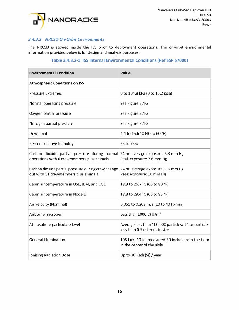
3.4.3.2 NRCSD On-Orbit Environments
The NRCSD is stowed inside the ISS prior to deployment operations. The on-orbit environmental information provided below is for design and analysis purposes.
Table 3.4.3.2-1: ISS Internal Environmental Conditions (Ref SSP 57000)
Environmental Condition Value
Atmospheric Conditions on ISS
Pressure Extremes 0 to 104.8 kPa (0 to 15.2 psia)
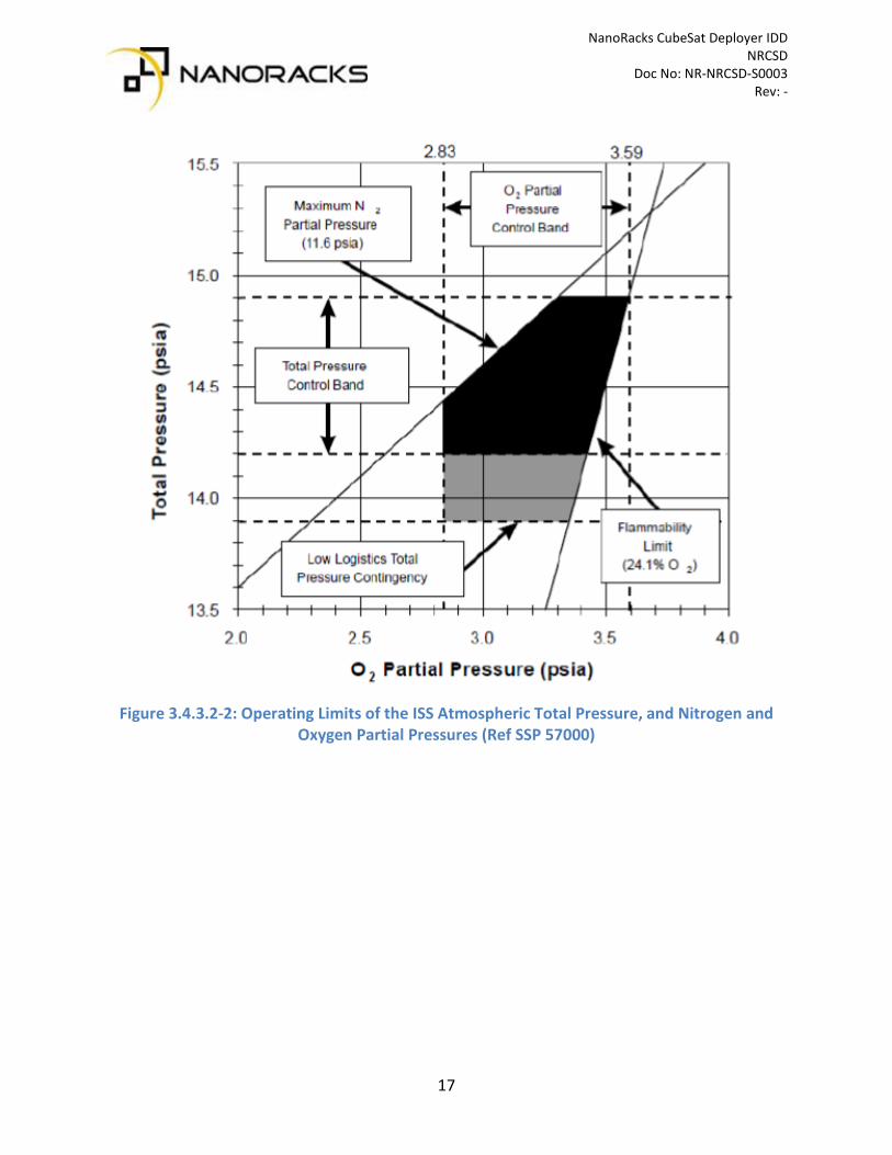
Normal operating pressure See Figure 3.4-2
Oxygen partial pressure See Figure 3.4-2
Nitrogen partial pressure See Figure 3.4-2
Dew point 4.4 to 15.6 °C (40 to 60 °F)
Percent relative humidity 25 to 75%
Carbon dioxide partial pressure during normal operations with 6 crewmembers plus animals
24 hr. average exposure: 5.3 mm Hg Peak exposure: 7.6 mm Hg
Carbon dioxide partial pressure during crew change out with 11 crewmembers plus animals
24 hr. average exposure: 7.6 mm Hg Peak exposure: 10 mm Hg
Cabin air temperature in USL, JEM, and COL 18.3 to 26.7 °C (65 to 80 °F)
Cabin air temperature in Node 1 18.3 to 29.4 °C (65 to 85 °F)
Air velocity (Nominal) 0.051 to 0.203 m/s (10 to 40 ft/min)
Airborne microbes Less than 1000 CFU/m3
Atmosphere particulate level Average less than 100,000 particles/ft3 for particles less than 0.5 microns in size
General Illumination 108 Lux (10 fc) measured 30 inches from the floor in the center of the aisle
Ionizing Radiation Dose Up to 30 Rads(Si) / year
NanoRacks CubeSat Deployer IDD NRCSD Doc No: NR-NRCSD-S0003 Rev: -
17
Figure 3.4.3.2-2: Operating Limits of the ISS Atmospheric Total Pressure, and Nitrogen and
Oxygen Partial Pressures (Ref SSP 57000)

NanoRacks CubeSat Deployer IDD NRCSD Doc No: NR-NRCSD-S0003 Rev: -
18
3.4.3.3 NRCSD On-Orbit Interfaces
The JEM Airlock is the facility on the ISS utilized to transport the NRCSD from the pressurized volume to the extra-vehicular environment of ISS. The NRCSD mounts to the Multi-Purpose Experiment Platform (MPEP), which in turn mounts to the JEM Airlock Slide Table. Depending on the mission complement, NanoRacks may deploy CubeSats using both the NRCSD and the NanoRacks DoubleWide Deployer (NRDD) on the same airlock cycle / mission. An example of an integrated NRCSD mission configuration on the MPEP is displayed in Figure 3.4.3.3-1.
Figure 3.4.3.3-1: NRCSD Standard and DoubleWide on MPEP
A Multi-Layer Insulation (MLI) thermal blanket is secured around the NRCSD top-level mission assembly prior to JEM Airlock depress.
The JEM Remote Manipulator System (JEMRMS) is the Extravehicular Robotics (EVR) system that grapples the MPEP, removes the integrated assembly from the JEM airlock slide table, and positions the NRCSDs for deployment. The NRCSD release mechanism receives power from the NanoRacks Launch Command Multiplexer (LCM), which in turn receives power/data from the MPEP via the JEMRMS.

NanoRacks CubeSat Deployer IDD NRCSD Doc No: NR-NRCSD-S0003 Rev: -
19
3.4.3.4 JEM Operation / Deployment from ISS
The JEM operations are managed by JAXA ground controllers. Once the ISS Program schedules the CubeSat deployment window (subject to various constraints such as visiting vehicle traffic, crew time, etc.) the on-orbit crew is responsible for unpacking the loaded NRCSDs and assembling the deployers onto the MPEP and JEM slide table (along with the LCM and associated cables). The NanoRacks operations team provides support to the crew in all aspects of the assembly in coordination with ISS Payload Operations Integration Function (POIF). The standard concept of operations for the NRCSD hardware is outlined below (see Figure 3.4-4, Figure 3.4-5, and Figure 3.4-6):
• MPEP is installed onto the JEM Airlock Slide Table • NRCSDs are mechanically installed on the MPEP along with the LCM • NRCSD jack screws, jam nuts, and thumb screws are removed • NRCSDs are electrically connected to the LCM, which in turn is connected to the MPEP
using NanoRacks on-orbit cables • The NRCSD/MPEP assembly is covered with an MLI thermal blanket • The JEM Airlock Slide Table maneuvers the assembly into the airlock • The JEM Airlock inner hatch is closed • The JEM Airlock is depressurized • The JEM Airlock outer hatch is opened • The JEM Airlock Slide Table maneuvers outside the ISS • The JEMRMS grapples the MPEP/NRCSD assembly by the grapple fixture located on the
MPEP and translates it to the pre-approved deployment position (pointed retrograde to the ISS).
• JAXA ground controllers send the deployment command to the NRCSD via ISS CD&H backbone and then a single NRCSD deploys one silo of CubeSats. There may be more than one CubeSat in a single silo depending on the form factor. Deployment of the satellite(s) is captured by ISS external cameras to verify good deployment.
• The NRCSD/MPEP assembly is returned to the JEM Airlock and reverse steps taken to remove NRCSDs from JEM Airlock Slide Table
• NRCSDs are packed for return to Earth or on-orbit disposal on appropriate ISS cargo resupply vehicle

NanoRacks CubeSat Deployer IDD NRCSD Doc No: NR-NRCSD-S0003 Rev: -
20
Figure 3.4.3.4-1: JEM Airlock Slide Table
Figure 3.4.3.4-2: JEM Overview
Figure 3.4.3.4-3: NRCSD Deployment of Three (3) CubeSats from ISS (Photo Credit: NASA)

NanoRacks CubeSat Deployer IDD NRCSD Doc No: NR-NRCSD-S0003 Rev: -
21
4 Payload Interface Requirements
The requirements contained in this section shall be complied with in order to certify the payload for integration into the NRCSD, launch and stowage inside an ISS cargo resupply vehicle, and operation with the JEM module via the NRCSD and associated support hardware. The requirements are presented in the following categories: Structural and Mechanical Systems, Electrical, Environmental, Safety, Jettison, and Documentation. In the event a requirement cannot be adhered to, exceptions are often possible depending on the nature of the noncompliance. All required exceptions and associated acceptance rationale shall be captured in the unique payload ICA.
4.1 Structural and Mechanical Systems Interface Requirements The NRCSD is designed to accommodate any combination of 1U, 2U, 3U, 4U, or 5U CubeSats up to a maximum volume of 6U, or a single 6U CubeSat in the 1x6x1U form factor. The only dimensional requirement that varies between the form factors is the total length (Z-axis dimension), which is specifically noted in the requirements herein. This section captures all mechanical and dimensional requirements to ensure the payloads interface correctly with the NRCSD and adjacent CubeSats.
4.1.1 CubeSat Mechanical Specification
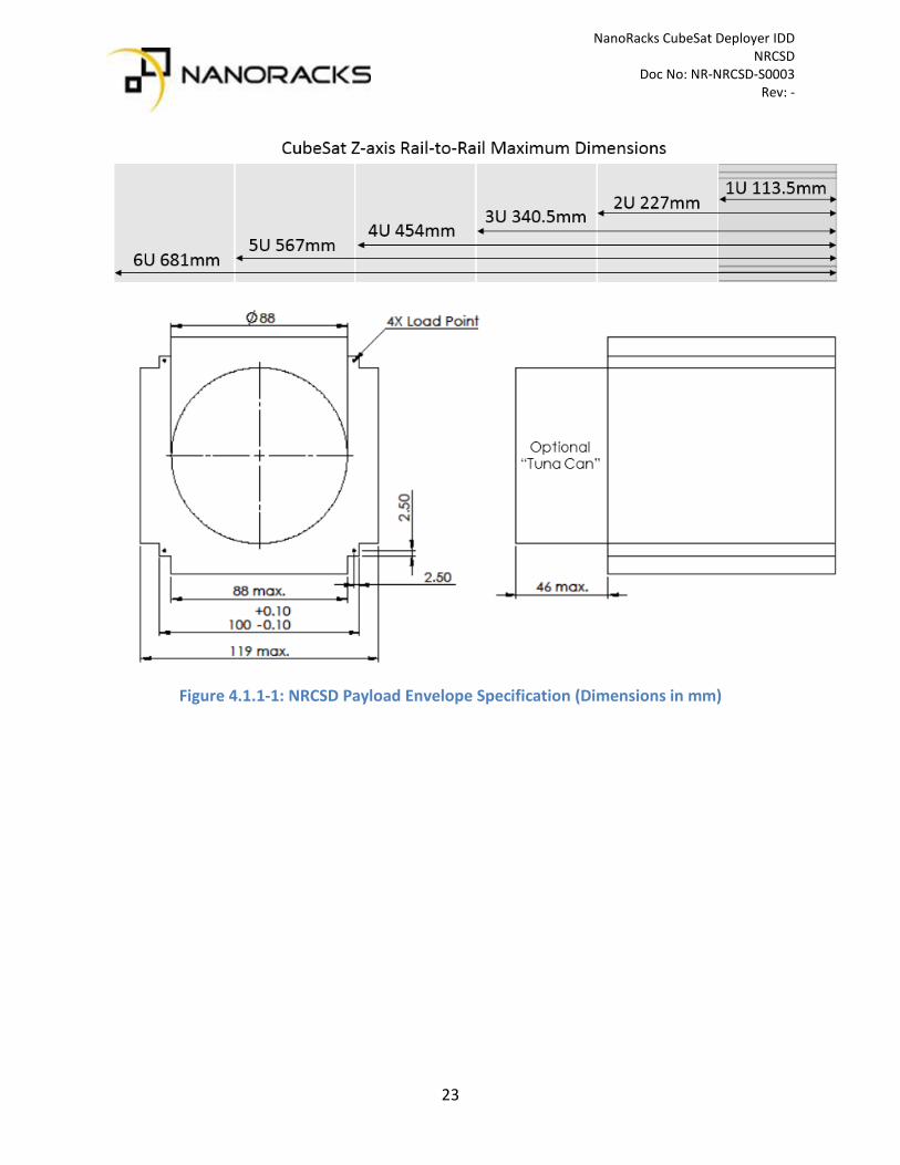
1) The CubeSat shall have four (4) rails along the Z axis, one per corner of the payload envelope, which allow the payload to slide along the rail interface of the NRCSD as outlined in Figure 4.1-1.
2) The CubeSat rails and envelope shall adhere to the dimensional specification outlined in Figure 4.1-1. Note: Any dimension followed by ‘MIN’ shall be considered a minimum dimensional requirement for that feature and any dimension followed by ‘MAX’ shall be considered a maximum dimensional requirement for that feature. Any dimension that has a required tolerance is specified in Figure 4.1-2. The optional cylindrical payload envelope (the ‘tuna can’) must be approved for use by NanoRacks and special accommodations may be required if utilizing this feature.
3) Each CubeSat rail shall have a minimum width (X and Y faces) of 6mm. 4) The edges of the CubeSat rails shall have a radius of 0.5mm +/- 0.1mm. 5) The CubeSat +Z rail ends shall be completely bare and have a minimum surface area of 6mm x
6mm. Note: This is to ensure that CubeSat +Z rail ends can serve as the mechanical interface for adjacent CubeSat deployment switches / springs.
6) The CubeSat rail ends (+/-Z) shall be coplanar with the other rail ends within +/- 0.1mm. 7) The CubeSat rail length (Z axis) shall be the following (+/-0.1mm):
a. 1U rail length: 113.50mm b. 2U rail length: 227.00mm

NanoRacks CubeSat Deployer IDD NRCSD Doc No: NR-NRCSD-S0003 Rev: -
22
c. 3U rail length: 340.50mm d. 4U rail length: 454.00mm e. 5U rail length: 567.5mm f. 6U rail length: 681 to 740.00mm
Note: Non-standard payload lengths may be considered. Any rail length differing from the above dimensions must be approved by NanoRacks and recorded in the unique payload ICA.
8) The CubeSat rails shall be continuous. No gaps, holes, fasteners, or any other features may be present along the length of the rails (Z-axis) in regions that contact the NRCSD rails. Note: This does not apply to roller switches located within the rails. However, the roller switches must not impede the smooth motion of the rails across surfaces (NRCSD guide rails, fit gauge, etc.)
9) The minimum extension of the +/-Z CubeSat rails from the +/-Z CubeSat faces shall be 2mm. Note: This means that the plane of the +/-Z rails shall have no less than 2mm clearance from any external feature on the +/-Z faces of the CubeSat (including solar panels, antennas, etc).
10) The CubeSat rails shall be the only mechanical interface to the NRCSD in all axes (X, Y and Z axes). Note: For clarification, this means that if the satellite is moved in any direction while inside the NRCSD, the only contact points of the payload shall be on the rails or rail ends. No appendages or any part of the satellite shall contact the walls of the deployer.
11) The CubeSat rail surfaces that contact the NRCSD guide rails shall have a hardness equal to or greater than hard-anodized aluminum (Rockwell C 65-70). Note: NanoRacks recommends a hard-anodized aluminum surface.
12) The CubeSat rails and all load points shall have a surface roughness of less than or equal to 1.6 µm.
Figure 4.1.1-1: NRCSD Mechanical Interface (Dimensions in mm)
NanoRacks CubeSat Deployer IDD NRCSD Doc No: NR-NRCSD-S0003 Rev: -
23
Figure 4.1.1-1: NRCSD Payload Envelope Specification (Dimensions in mm)

NanoRacks CubeSat Deployer IDD NRCSD Doc No: NR-NRCSD-S0003 Rev: -
24
4.1.2 CubeSat Mass Properties
1) The CubeSat mass shall be less than the maximum allowable mass for each respective payload form factor per Table 4.1.2-1. Note: The requirement driver for the CubeSat mass is the ballistic number (BN), which is dependent on the projected surface area of the payload on-orbit. The mass values in Table 4-1 assume no active or passive attitude control of the payload once deployed. If the CubeSat has attitude control capabilities or design features, then the operational ballistic number (BN) will drive the mass requirement. If applicable, this shall be captured in the unique payload ICA.
Table 4.1.2-1: CubeSat Mass Limits
Form Factor Maximum Mass (kg)
1U 2.40
2U 3.60
3U 4.80
4U 6.00
5U 7.20
6U 8.40
2) The CubeSat center of mass (CM) shall be located within the following range relative to the geometric center of the payload.
a. X-axis: (+/- 2cm) b. Y-axis: (+/- 2cm) c. Z-axis:
i. 1U: (+/- 2cm) ii. 2U (+/- 4cm)
iii. 3U (+/- 6cm) iv. 4U (+/- 8cm) v. 5U (+/- 10cm)
vi. 6U (+/- 12cm)
4.1.3 RBF / ABF Access
1) The CubeSat shall have a remove before flight (RBF) feature or an apply before flight (ABF) feature. The RBF / ABF shall be physically accessible via the NRCSD access panels on the +Y face of the dispenser. Note: There is no physical access to the payload after integration into the NRCSD besides what can be accessed from the access panels.

NanoRacks CubeSat Deployer IDD NRCSD Doc No: NR-NRCSD-S0003 Rev: -
25
4.1.4 Deployment Switches
1) The CubeSat shall have a minimum of three (3) deployment switches that correspond to independent electrical inhibits on the main power system (see section on electrical interfaces).
2) Deployment switches of the pusher/plunger variety shall be located on the rail end faces of the CubeSat’s -Z face.
3) Deployment switches of the roller/lever variety shall be embedded in the CubeSat rails (+/- X or Y faces).
4) Roller/slider switches shall maintain contact with 75% of the NRCSD rail width along the entire length of the rail.
5) The CubeSat deployment switches shall reset the payload to the pre-launch state if cycled at any time within the first 30 minutes after the switches close (including but not limited to radio frequency transmission and deployable system timers).
6) The CubeSat deployment switches shall be captive. 7) The force exerted by the deployment switches shall not exceed 3N. 8) The total force of all CubeSat deployment switches shall not exceed 9N.
4.1.5 Deployable Systems and Integration Constraints
1) CubeSat deployable systems (such as solar arrays, antennas, payload booms, etc.) shall have independent restraint mechanisms that do not rely on the NRCSD dispenser. Note: Passive deployables that release upon ejection of the CubeSat from the NRCSD will be considered on a case-by-case basis.
2) The CubeSat shall be capable of being integrated forwards and backwards inside of the NRCSD (such that the +/-Z face could be deployed first without issue). Note: In general, the deployables should be hinged towards the front of the deployer to mitigate risk of a hang-fire should the deployables be released prematurely while the CubeSat is still inside the NRCSD.
4.1.6 Deployment Velocity and Tip-Off Rate Compatibility
1) The CubeSat shall be capable of withstanding a deployment velocity of 0.5 to 2.0 m/s at ejection from the NRCSD.
2) The CubeSat shall be capable of withstanding up to five (5) deg/sec/axis tip-off rate. Note: The target tip-off rate of the NRCSD is less than two (2) deg/sec/axis. If a payload has specific tip-off rate requirements, these should be captured in the unique payload ICA.
NanoRacks CubeSat Deployer IDD NRCSD Doc No: NR-NRCSD-S0003 Rev: -
26
4.2 Electrical System Interface Requirements CubeSat electronic system designs shall adhere to the following requirements.
4.2.1 Electrical System Design and Inhibits
1) All electrical power storage devices shall be internal to the CubeSat. 2) CubeSat shall not operate any system (including RF transmitters, deployment mechanisms or
otherwise energize the main power system) for a minimum of 30 minutes where hazard potential exists. Satellites shall have a timer (set to a minimum of 30 minutes and require appropriate fault tolerance) before satellite operation or deployment of appendages where hazard potential exists.
3) The CubeSat electrical system design shall incorporate a minimum of three (3) independent inhibit switches actuated by physical deployment switches as shown in Figure 4.2-1. The satellite inhibit scheme shall include a ground leg inhibit (switch D3 on Figure 4.2-1) that disconnects the batteries along the power line from the negative terminal to ground. Note: This requirement considers an inhibit as a power interrupt device. A control for an inhibit (electrical or software) cannot be counted as an inhibit or power interrupt device. The requirement for three (3) inhibits is based on the worst-case assumption that the CubeSat contains a potential catastrophic hazard that exists in the event of an inadvertent power-up while inside the NRCSD. However, the electrical system design shall incorporate an appropriate number of inhibits dictated by the hazard potential of the payload. If this requirement cannot be met, a hazard assessment can be conducted by NanoRacks to determine if an exception can be granted and documented in the unique payload ICA.
4) The CubeSat electrical system design shall not permit the ground charge circuit to energize the satellite systems (load), including flight computer (see Figure 4.2-1). This restriction applies to all charging methods.
5) The CubeSat shall have a remove before flight (RBF) feature or an apply before flight (ABF) feature that keeps the satellite in an unpowered state throughout the ground handling and integration process into the NRCSD. Note: The RBF pin is required in addition to the three (3) inhibit switches. See Section 4.1.2 for details on mechanical access while the payload is inside the NRCSD.
6) The RBF /ABF feature shall preclude any power from any source operating any satellite functions with the exception of pre-integration battery charging.
7) The CubeSat Electrical Power System (EPS) shall have no more than six (6) inches of wire 26AWG or larger between the power source (i.e. battery pack) and the first electrical inhibit. Note: If more than six (6) inches of wire is required between the batteries and the first electrical inhibit, then SAE AS22759 or equivalent wiring shall be utilized. Wiring shall be insulated with Polytetrafluoroethylene (PTFE) or Ethylene tetrafluoroethylene (ETFE) and adhere to the 200°C wire rating outlined on Page 2-8 of TA-92-038 (can be provided by NanoRacks).

NanoRacks CubeSat Deployer IDD NRCSD Doc No: NR-NRCSD-S0003 Rev: -
27
Figure 4.2.1-1: CubeSat Electrical Subsystem Block Diagram (Note: RBF pins not shown)
4.2.2 Electrical System Interfaces
1) There shall be no electrical or data interfaces between the CubeSat and the NRCSD. As outlined in Section 4.2, the CubeSat shall be completely inhibited while inside the NRCSD.
NanoRacks CubeSat Deployer IDD NRCSD Doc No: NR-NRCSD-S0003 Rev: -
28
4.3 Environmental Interface Requirements
4.3.1 Acceleration Loads
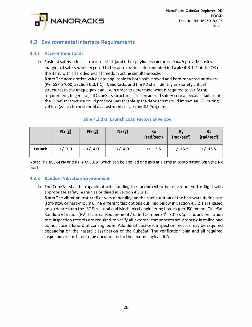
1) Payload safety critical structures shall (and other payload structures should) provide positive margins of safety when exposed to the accelerations documented in Table 4.3.1-1 at the CG of the item, with all six degrees of freedom acting simultaneously. Note: The acceleration values are applicable to both soft-stowed and hard-mounted hardware (Per SSP 57000, Section D.3.1.1). NanoRacks and the PD shall identify any safety critical structures in the unique payload ICA in order to determine what is required to verify this requirement. In general, all CubeSats structures are considered safety critical because failure of the CubeSat structure could produce untrackable space debris that could impact an ISS visiting vehicle (which is considered a catastrophic hazard by ISS Program).
Table 4.3.1-1: Launch Load Factors Envelope
Nx (g) Ny (g) Nz (g) Rx (rad/sec2)
Ry (rad/sec2)
Rz (rad/sec2)
Launch +/- 7.0 +/- 4.0 +/- 4.0 +/- 13.5 +/- 13.5 +/- 13.5
Note: The RSS of Ny and Nz is +/-1.8 g, which can be applied one axis at a time in combination with the Nx load.
4.3.2 Random Vibration Environment
1) The CubeSat shall be capable of withstanding the random vibration environment for flight with appropriate safety margin as outlined in Section 4.3.2.1. Note: The vibration test profiles vary depending on the configuration of the hardware during test (soft-stow or hard-mount). The different test options outlined below in Section 4.3.2.1 are based on guidance from the JSC Structural and Mechanical engineering branch (per JSC memo ‘CubeSat Random Vibration (RV) Technical Requirements’ dated October 24th, 2017). Specific post-vibration test inspection records are required to verify all external components are properly installed and do not pose a hazard of coming loose. Additional post-test inspection records may be required depending on the hazard classification of the CubeSat. The verification plan and all required inspection records are to be documented in the unique payload ICA.
NanoRacks CubeSat Deployer IDD NRCSD Doc No: NR-NRCSD-S0003 Rev: -
29
4.3.2.1 Random Vibration Test Options
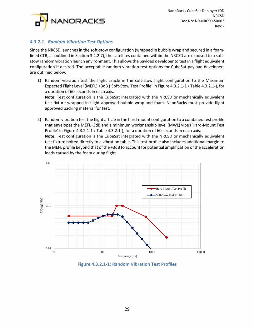
Since the NRCSD launches in the soft-stow configuration (wrapped in bubble wrap and secured in a foam-lined CTB, as outlined in Section 3.4.2.7), the satellites contained within the NRCSD are exposed to a soft-stow random vibration launch environment. This allows the payload developer to test in a flight equivalent configuration if desired. The acceptable random vibration test options for CubeSat payload developers are outlined below.
1) Random vibration test the flight article in the soft-stow flight configuration to the Maximum Expected Flight Level (MEFL) +3dB (‘Soft-Stow Test Profile’ in Figure 4.3.2.1-1 / Table 4.3.2.1-), for a duration of 60 seconds in each axis. Note: Test configuration is the CubeSat integrated with the NRCSD or mechanically equivalent test fixture wrapped in flight approved bubble wrap and foam. NanoRacks must provide flight approved packing material for test.
2) Random vibration test the flight article in the hard-mount configuration to a combined test profile that envelopes the MEFL+3dB and a minimum workmanship level (MWL) vibe (‘Hard-Mount Test Profile’ in Figure 4.3.2.1-1 / Table 4.3.2.1-), for a duration of 60 seconds in each axis. Note: Test configuration is the CubeSat integrated with the NRCSD or mechanically equivalent test fixture bolted directly to a vibration table. This test profile also includes additional margin to the MEFL profile beyond that of the +3dB to account for potential amplification of the acceleration loads caused by the foam during flight.
Figure 4.3.2.1-1: Random Vibration Test Profiles
0.01
0.10
1.00
10 100 1000 10000
ASD
(g2/
Hz)
Frequency (Hz)
Hard-Mount Test Profile
Soft-Stow Test Profile

NanoRacks CubeSat Deployer IDD NRCSD Doc No: NR-NRCSD-S0003 Rev: -
30
Table 4.3.2.1-1: Random Vibration Test Profiles
Soft-Stow Test Profile Hard-Mount Test Profile Frequency (Hz) ASD (g2/Hz) Frequency (Hz) ASD (g2/Hz)
20 4.000E-02 20 5.700E-02 25 4.000E-02 153 5.700E-02
31.5 4.000E-02 190 9.900E-02 40 4.000E-02 250 9.900E-02 50 4.000E-02 750 5.500E-02 63 4.490E-02 2000 1.800E-02 80 5.062E-02 grms 9.47
100 5.660E-02 Duration (sec) 60 125 6.200E-02 160 6.200E-02 200 6.200E-02 250 5.558E-02 315 4.102E-02 400 2.998E-02 500 2.236E-02 630 1.651E-02 800 1.206E-02
1000 9.000E-03 1250 6.034E-03 1600 3.878E-03 2000 2.600E-03 grms 5.76
Duration (sec) 60
4.3.3 Launch Shock Environment
Integrated end items packed in the soft-stow configuration do not experience significant mechanical shock. As a result, there is no shock test requirement for CubeSats launching inside the NRCSD. Any mechanical or electrical components on the spacecraft that are highly sensitive to shock should still be identified and assessed on a case-by-case basis as defined in the unique payload ICA.
NanoRacks CubeSat Deployer IDD NRCSD Doc No: NR-NRCSD-S0003 Rev: -
31
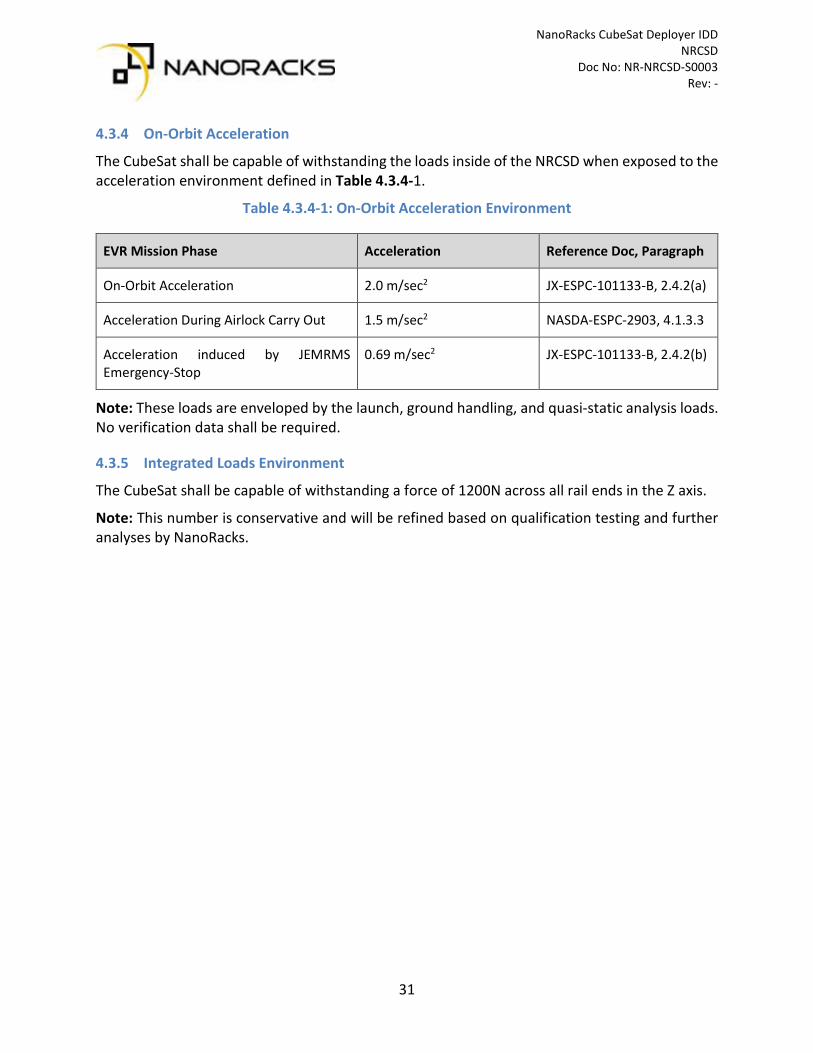
4.3.4 On-Orbit Acceleration
The CubeSat shall be capable of withstanding the loads inside of the NRCSD when exposed to the acceleration environment defined in Table 4.3.4-1.
Table 4.3.4-1: On-Orbit Acceleration Environment
EVR Mission Phase Acceleration Reference Doc, Paragraph
On-Orbit Acceleration 2.0 m/sec2 JX-ESPC-101133-B, 2.4.2(a)
Acceleration During Airlock Carry Out 1.5 m/sec2 NASDA-ESPC-2903, 4.1.3.3
Acceleration induced by JEMRMS Emergency-Stop
0.69 m/sec2 JX-ESPC-101133-B, 2.4.2(b)
Note: These loads are enveloped by the launch, ground handling, and quasi-static analysis loads. No verification data shall be required.
4.3.5 Integrated Loads Environment
The CubeSat shall be capable of withstanding a force of 1200N across all rail ends in the Z axis.
Note: This number is conservative and will be refined based on qualification testing and further analyses by NanoRacks.

NanoRacks CubeSat Deployer IDD NRCSD Doc No: NR-NRCSD-S0003 Rev: -
32
4.3.6 Thermal Environment
The CubeSat shall be capable of withstanding the expected thermal environments for all mission phases, which are enveloped by the on-orbit, EVR phase prior to deployment. The expected thermal environments for all phases of the mission leading up to deployment are below in Table 4-5.
Note: The on-orbit temperature extremes for the EVR phase prior to deployment are to be considered worst-case extremes based on the results of the thermal analysis conducted for the NRCSD. The thermal analysis was conducted based on worst-case atmospheric conditions that are expected to be exceeded no more than 0.5% of the time, with albedo and outgoing longwave radiation (OLR) adjusted to the top of the atmosphere (30-kilometer altitude) per SSP 41000 Table XXV. The solar loading conditions for these also took into account extreme beta angle conditions of 73 degrees and -60 degrees as dictated by JAXA.
Table 4.3.6-1: Expected Thermal Environments
Mission Phase Temperature Extremes Ground Transport (Customer facility to NanoRacks) Determined for each payload Ground Processing NanoRacks Determined for each payload Ground Processing NASA / JAXA Envelope 10°C to 35°C Dragon Pressurized Cargo 18.3°C to 29.4°C Cygnus Pressurized Cargo 10°C to 46°C HTV Pressurized Cargo 0°C to 50°C On-orbit, Pre-deployment, U.S. and JEM Modules 16.7°C to 28.3°C On-orbit, EVR Prior to Deployment -10°C to 45°C
Ref SSP 50835, Table E.2.10-1
4.3.7 Humidity
The CubeSat shall be capable of withstanding the relative humidity environment for all mission phases leading up to deployment, which is between 25% to 75% relative humidity (RH) for ascent and on-orbit phases of flight.
Note: Special consideration may be possible for payload with more stringent RH requirements. These requirements shall be captured in the unique payload ICA and special handling requirements negotiated directly with NanoRacks.

NanoRacks CubeSat Deployer IDD NRCSD Doc No: NR-NRCSD-S0003 Rev: -
33
4.3.8 Airlock Depressurization
The CubeSat shall be capable of withstanding the pressure extremes and depressurization / pressurization rate of the airlock as defined below.
Airlock Pressure: 0 to 104.8 kPa
Airlock pressure depressurization/re-pressurization rate: 1.0 kPa/sec
Note: Verification of this requirement completed by ensuring the payload adheres to the venting requirements outlined in Section 4.4.2.
4.4 Safety Requirements CubeSats shall be designed to preclude or control all hazards present according to the requirements and guidelines outlined in this section. The following sections contain the specific safety requirements common to standard CubeSat designs. In many cases though, the specific design requirements are dependent on the hazard classification of the CubeSat (particularly for CubeSats with non-standard design features). While NanoRacks is responsible for performing the hazard classification for all payloads (with ultimate concurrence from the ISS PSRP), the general guidelines of the process have been outlined below and should be considered background info for the PD.
In general, hazards are classified according to the following definitions:
1) Catastrophic Hazard Definition – Any condition that may result in the potential for: • A disabling or fatal personnel injury, • Loss of the ISS, • Loss of a crew-carrying vehicle • Loss of a major ground facility
SSP 50700 paragraph 3.1.1.2 Catastrophic HAZARDS - The payload shall be designed such that no combination of two failures, two operator errors (or one of each), can cause a disabling or fatal personnel injury or loss of one of the following: loss of ISS, loss of a crew-carrying vehicle, or loss of major ground facility.
2) Critical Hazard Definition - Any condition that may result in either: • A non-disabling personnel injury or illness • Loss of a major ISS element • Loss of redundancy (i.e. with only a single hazard control remaining) for on-orbit life
sustaining function SSP 51700 paragraph 3.1.1.1 CRITICAL HAZARDS - The payload shall be designed such that no single failure or single operator error can cause a non-disabling personnel injury or illness, loss of a major ISS element, loss of redundancy (i.e. with only a single hazard control remaining) for on-orbit life sustaining function, or loss of use of the Space Station Remote Manipulator System (SSRMS).
NanoRacks CubeSat Deployer IDD NRCSD Doc No: NR-NRCSD-S0003 Rev: -
34
3) Marginal Hazard Definition - Any condition which may cause damage to: • An ISS element in a non-critical path • A personnel injury causing minor crew discomfort that does not require medical
intervention from a second crewmember and/or consultation with a Flight Surgeon Some examples of CubeSat features/failures that are assessed for hazard potential are:
• Structure Failure o Inability to sustain applied loads o Fracture o Stress corrosion o Mechanisms o Fastener integrity and secondary locking features
• Pressure System Failure o Explosion o Rupture
• Leakage of, or exposure to, hazardous or toxic substances • Propulsion System Hazards
o Including inadvertent operation • Deployment of appendages • RF system operation hazard to ISS hardware and Crew • Battery Failure • Flammable or toxic material usage • Frangible material usage • Electrical system failures causing shock or burn
o Includes wiring, fusing, grounding • Electromagnetic Interference (EMI) • Magnetic field • Collision with ISS or Visiting Vehicles post deploy on subsequent orbits • Operational procedures
Control of hazards shall be appropriate for the hazard type and occurrence. Many CubeSat Hazards are controlled by the deployer itself since the CubeSat is contained in the deployer while at ISS until deployment. Some examples of other controls are:
• Structural hazards o Application of factor of safety with positive margin
Supports design for minimum risk o Fault tolerance where applicable
Controlled by remaining elements not failing under resulting load Redundant mechanisms
• Electrically operated systems o Inhibits to control inadvertent operations appropriate to the hazard level o Redundancy as necessary to perform required functions o Design controls

NanoRacks CubeSat Deployer IDD NRCSD Doc No: NR-NRCSD-S0003 Rev: -
35
• Leakage of toxic substances o Fault tolerance in seals o Structural strength of containers o Multiple levels of containment
• Flammable materials o Elimination of flammable materials o Containment o Wire sizing and fusing
• Pressure systems o Factor of safety o Venting
• RF systems o Design to have power below hazard level and frequency in approved range o Inhibits to control inadvertent operations appropriate to the hazard level
• Battery hazards o Containment o Protection circuits o Separation to prevent thermal runaway propagation o Screening and testing
4.4.1 Containment of Frangible Materials
The CubeSat design shall preclude the release or generation of any foreign object debris (FOD) for all mission phases.
Note: The primary concern is exposed frangible materials on the satellite exterior (solar cell cover glass, optical lenses, etc). For most frangible materials on CubeSats, a containment or protection method is not required (however all frangible materials shall be identified in the payload unique ICA for NanoRacks review).
4.4.2 Venting
The Maximum Effective Vent Ratio (MEVR) of the CubeSat structure and any enclosed containers internal to the CubeSat shall not exceed 5080cm.
The MEVR is calculated as follows:
𝑀𝑀𝑀𝑀𝑀𝑀𝑀𝑀 = �𝐼𝐼𝐼𝐼𝐼𝐼𝐼𝐼𝐼𝐼𝐼𝐼𝐼𝐼𝐼𝐼 𝑀𝑀𝑉𝑉𝐼𝐼𝑉𝑉𝑉𝑉𝐼𝐼 (𝑐𝑐𝑉𝑉)3
𝑀𝑀𝐸𝐸𝐸𝐸𝐼𝐼𝑐𝑐𝐼𝐼𝐸𝐸𝐸𝐸𝐼𝐼 𝑀𝑀𝐼𝐼𝐼𝐼𝐼𝐼 𝐴𝐴𝐼𝐼𝐼𝐼𝐼𝐼 (𝑐𝑐𝑉𝑉)2 � ≤ 5080 𝑐𝑐𝑉𝑉
Effective vent area shall be considered as the summation of the unobstructed surface area of any vent hole locations or cross-sectional regions that air could escape the CubeSat or subsystems.

NanoRacks CubeSat Deployer IDD NRCSD Doc No: NR-NRCSD-S0003 Rev: -
36
4.4.3 Secondary Locking Feature
The CubeSat shall have an approved secondary locking feature for any and all fasteners or subcomponents external to the CubeSat chassis that would not be held captive by the spacecraft structure should it come loose.
Note: The measured and recorded fastener torque is considered the primary locking feature for fasteners. Mechanical or liquid locking compounds are approved. Mechanical secondary locking features are preferred and may be either a locking receptacle such as a locking helical insert or locknut. Approved thread locking compounds include Loctite® Threadlocker Red 271™ and Blue 242™. Contact NanoRacks to determine what other commonly used locking compounds have been approved for use and for appropriate application instructions. The secondary locking feature for all external fasteners and the application procedure of all liquid locking compounds shall be approved by NanoRacks and documented in the unique payload ICA.
4.4.4 Passivity
The CubeSat shall be passive and self-contained from the time of integration up to the time of deployment.
Note: No charging of batteries, support services, and or support from ISS crew is provided after final integration.
4.4.5 Pyrotechnics
The CubeSat shall not contain any pyrotechnics unless the design approach is approved by NanoRacks.
Note: Electrically operated melt-wire systems for deployables that are necessary controls for hazard potentials are permitted.
4.4.6 Space Debris Compliance
1) CubeSats shall not have detachable parts during launch or normal mission operations. Any exceptions will be coordinated with NanoRacks and documented in the unique payload ICA.
2) CubeSats shall comply with NASA space debris mitigation guidelines as documented in NASA Technical Standard NASA-STD-8719.14A.

NanoRacks CubeSat Deployer IDD NRCSD Doc No: NR-NRCSD-S0003 Rev: -
37
4.4.7 Batteries
All cells / batteries on the CubeSat shall adhere to the design and testing requirements for spacecraft flight onboard or near the ISS as derived from the NASA requirement document JSC 20793 Crewed Space Vehicle Battery Safety Requirements. Specific provisions for battery use are designed to assure that a battery is safe for ground personnel and ISS crew members to handle and/or operate during all applicable mission phases and particularly in an enclosed environment of a crewed space vehicle. These NASA provisions also assure that the battery is safe for use in launch vehicles, as well as in unpressurized spaces adjacent to the habitable portion of a space vehicle. The required provisions encompass hazard controls, design evaluation, and verification. Evaluation of the battery system must be complete prior to certification for flight and ground operations. Certain battery cell chemistries and battery configurations may trigger higher scrutiny to protect against thermal runaway propagation.
It is imperative that NanoRacks receive all requested technical data as early as possible to assure the necessary safety features are present to control the hazards associated with a particular battery design and to identify all necessary verifications and testing required (as documented in the unique payload ICA). Redesign efforts greatly impact the payload developer both in cost and schedule. Consult with NanoRacks before hardware is manufactured. Cell/Battery testing associated with the verification of the safety compliance shall be completed as part of the safety certification of the spacecraft. To comply with the requirements herein, every battery design, along with its safety verification program, its ground and/or on-orbit usage plans, and its post-flight processing shall be evaluated and approved by the appropriate technical review panel in the given program or project and captured in the unique payload ICA.
4.4.7.1 Battery Hazards
The possible sources of battery hazards are listed below and shall be identified for each battery system. Applicable hazards will be evaluated to determine and to identify design, workmanship, and other features to be used for hazard control (electrical, mechanical, and/or thermal).
Potential Battery Hazards: • Fire/Explosion/Flammability • Venting/Burst of Battery Enclosure • Overcharge Failure/Over-discharge Failure • External Short Circuit • Internal Short Circuit Failure • Thermal Runaway Propagation/Extreme Temperature Hazards • Chemical Exposure Hazards

NanoRacks CubeSat Deployer IDD NRCSD Doc No: NR-NRCSD-S0003 Rev: -
38
4.4.7.2 Battery Types
Although any battery may be made safe to fly in the crewed space vehicle environment there are some batteries that are not practical to make safe. For example, lithium-sulfur dioxide cells have built-in overpressure vents that will release SO2 (sulfur dioxide) gas and other electrolyte components that are highly toxic; thus, these are unacceptable in the habitable area of a space vehicle. However, these chemistries have been used safely in the non-pressurized areas of crewed spacecraft. Often the cells used in batteries for crewed space vehicle are commercially available.
Battery types typically used in spacecraft include: • Alkaline-manganese primary • LeClanche (carbon-zinc) primary • Lead-acid secondary cells having immobilized electrolyte • Lithium/lithium-ion polymer secondary (including lithium-polymer variation) • Lithium metal anode primary cells having the following cathodic (positive) active materials • Poly-carbon monofluoride • Iodine • Manganese dioxide • Silver chromate • Sulfur dioxide (external to habitable spaces only) • Thionyl chloride • Thionyl chloride with bromine chloride complex additive (Li-BCX) • Iron disulfide • Lithium sulfur • Mercuric oxide-zinc primary • Nickel-cadmium secondary • Nickel-metal hydride secondary • Silver-zinc primary and secondary • Zinc-air primary • Sodium-sulfur secondary (external to habitable space) • Thermal batteries
Note: Pressurized battery chemistries require coordination with NanoRacks.
NanoRacks CubeSat Deployer IDD NRCSD Doc No: NR-NRCSD-S0003 Rev: -
39
4.4.7.3 Required Battery Flight Acceptance Testing
All flight cells and battery packs shall be subjected to an approved set of acceptance screening tests to ensure the cells will perform in the required load and environment without leakage or failure. While the specific test procedures vary depending on the type of battery, the majority of Lithium ion or Lithium polymer cells / batteries used in CubeSats can be tested to a standard statement of work issued by NanoRacks (NR-SRD-139). Some generic battery design requirements are outlined below.
Note: The battery test plan and verification approach shall be captured in the payload unique ICA. No testing shall be performed without the approval of NanoRacks.
4.4.7.4 Internal Short
Protection circuity and safety features shall be implemented at the cell level to prevent an internal short circuit.
• Application of all cells shall be reviewed by NanoRacks. • Charger circuit and protection circuit schematics shall be reviewed and evaluated for required
fault tolerance.
4.4.7.5 External Short
Protection circuity and safety features shall be implemented at the cell level to prevent an external short circuit.
• Circuit interrupters that are rated well below the battery's peak current source capability shall be installed in the battery power circuit. Interrupters may be fuses, circuit breakers, thermal switches, PTCs, or other effective devices. Circuit interrupters other than fuses shall be rated at a value that is equal to or lower than the maximum current that the cell is capable of handling without causing venting, smoke, explosion, fire, or thermal runaway.
• The battery case is usually grounded/bonded to the structure; the interrupters should be in the ground (negative) leg of a battery where the negative terminal is connected to ground. Where the circuit is “floating,” as in plastic battery cases used in those for portable electronic devices, the circuit interrupters can be placed in either leg. In either case, the circuit interrupters should be placed as close to the cell or battery terminals as the design will allow maximizing the zone of protection.
• All inner surfaces of metal battery enclosures should be anodized and/or coated with a non-electrically conductive electrolyte-resistant paint to prevent a subsequent short circuit hazard (if applicable).
• The surfaces of battery terminals on the outside of the battery case should be protected from accidental bridging.
• Battery terminals that pass through metal battery enclosures should be insulated from the case by an insulating collar or other effective means.
• Wires inside the battery case should be insulated, restrained from contact with cell terminals, protected against chafing, and physically constrained from movement due to vibration or shock.
• In battery designs greater than 50 Vdc, corona-induced short circuits (high-voltage induced gas breakdown) shall be prevented.

NanoRacks CubeSat Deployer IDD NRCSD Doc No: NR-NRCSD-S0003 Rev: -
40
4.4.7.6 Overvoltage and Undervoltage Protection
Protection circuitry and safety features shall be implemented at the cell level to prevent overvoltage or undervoltage conditions of the cell.
4.4.7.7 Battery Charging
It should be verified that the battery charging equipment (if not the dedicated charger) has at least two levels of control that will prevent it from causing a hazardous condition on the battery being charged.
Note: This does not apply if the CubeSat will not be charged at NanoRacks.
4.4.7.8 Battery Energy Density
Battery designs greater than 80 Wh energy employing high specific energy cells (greater than 80 watt-hours/kg, for example, lithium-ion chemistries) require additional assessment by NanoRacks due to potential hazard in the event of single-cell, or cell-to-cell thermal runaway.
Note: Any system over 80 Wh will require additional design scrutiny and testing (likely including destructive thermal runaway testing). It is possible that this additional testing may be avoided by implementing design features in the system, such as splitting up the cells into distinct battery packs less than 80 Wh and physically isolating them at opposite ends of the CubeSat (so that thermal runaway cannot propagate between packs). Other methods, such as reducing the state of charge of the batteries at the time of delivery, can be explored with the JSC Battery Safety team to reduce the risk of a thermal runaway event.
4.4.7.9 Lithium Polymer Cells
Lithium Polymer Cells i.e. “pouch cells” shall be restrained at all times to prevent inadvertent swelling during storage, cycling, and low pressure or vacuum environments with pressure restraints on the wide faces of the cells to prevent damage due to pouch expansion. Coordinate with NanoRacks for guidance on specific implementation.
4.4.7.10 Button Cells
Button cell or coin cell batteries are often used in COTS components to power real-time clocks (RTCs), watch-dog circuits, or secondary systems for navigation, communication, or attitude control. These batteries shall be clearly identified by part number and UL listed or equivalent.
Note: Flight acceptance screening testing of these cells is typically not required. Only a functional test of the system needs to be reported. NanoRacks will confirm requirements upon documentation of all coin cell part numbers in the unique payload ICA.
NanoRacks CubeSat Deployer IDD NRCSD Doc No: NR-NRCSD-S0003 Rev: -
41
4.4.7.11 Capacitors Used as Energy Storage Devices
Capacitors are used throughout today’s modern electronics. Capacitors used as energy storage devices are treated and reviewed like batteries. Hazards associated with leaking electrolyte can be avoided by using solid state capacitors. Any wet capacitors that utilize liquid electrolyte must be reported to NASA. The capacitor part number and electrolyte must be identified along with details of how the capacitor is used and any associated schematics.
Note: NanoRacks will advise on any required flight acceptance screening testing once the information has been captured in the payload unique ICA.
4.4.8 Pressure Vessels
A pressure vessel is defined by SSP 52005 as any sealed container with an internal pressure greater than 100 psia. A pressure vessel may be made acceptable for Flight Safety with proper controls for any hazard potential both for inside ISS and outside ISS. If a satellite has a pressure vessel, the PD shall provide documentation with respect to the materials used, tank history (including cycles and life time assessment) and control measures taken to assure tank integrity (damage control plan), testing performed, fracture control measures planned, inspection process and methods, etc. wherever hazard potential is present. All pressure vessels shall be certified by the Department of Transportation (DOT) or have a DOT issued waiver for transportation across the US. Use of non-DOT certified pressure vessels generally would not be permitted. Exceptions must be coordinated with NanoRacks during the pre-contract signing phase. Systems will have to demonstrate via test that required factors of safety are present for tanks, lines and fittings that can be exposed to pressure with 1 or 2 failures depending on hazard potential. Pressure vessels and components procured from third party vendors must have proper certification records or the PD must develop the appropriate records to assure that the systems are safe by meeting NASA requirements. NanoRacks will assist in negotiating with NASA to define the work and analysis necessary to meet the NASA requirements.
4.4.9 Propulsion System
The propulsion system will need to be assessed for hazard potential. NanoRacks will assist in the identification of hazards. Mechanical hazards may be related to pressure containment, flow containment, leakage, etc. Systems may also have hazard potential if inadvertent operation of the propulsion system in or around ISS could be catastrophic or critical. Depending on hazard potential, both mechanical and electrical fault tolerance may be required.
Systems with toxic propellant may not be allowed onboard ISS but might be approvable if outside ISS. Propellants with explosive potential may not be approvable. Acceptable propellant type must be coordinated with NanoRacks and documented in the ICA.

NanoRacks CubeSat Deployer IDD NRCSD Doc No: NR-NRCSD-S0003 Rev: -
42
4.4.10 Materials
4.4.10.1 Stress Corrosion Materials
Stress corrosion resistant materials from Table I of MSFC-SPEC-522 are preferred. Any use of stress corrosion susceptible materials (Table II) shall be coordinated with NanoRacks and documented in the ICA. Any use of Table III materials shall be avoided.
4.4.10.2 Hazardous Materials
Satellites shall comply with JSC 27472 (Rev B), JSC 63838 (Rev B), JSC 66869, and applicable NASA guidelines for hazardous materials. Beryllium, cadmium, mercury, silver or other materials prohibited by SSP-30233 shall not be used. Any use of hazardous materials shall be coordinated with NanoRacks and documented in the ICA.
4.4.10.3 Outgassing / External Contamination
Satellites shall comply with NASA guidelines for selecting all non-metallic materials based on available outgassing data. Satellites shall not utilize any non-metallic materials with a Total Mass Loss (TML) greater than 1.0 percent or a Collected Volatile Condensable Material (CVCM) value of greater than 0.1 percent.
Note: A Bill of Materials (BoM) must be provided to NanoRacks to verify all materials requirements are met. The BoM shall be provided in the template specified by NanoRacks and must include the vacuum-exposed surface areas of all non-metals. The ISS Space Environments Team screens the BoMs to ensure there are no external contamination concerns due to high-outgassing components. A bake-out is not required. The NASA website linked below is a useful source for obtaining outgassing data for materials.
https://outgassing.nasa.gov/
4.4.11 Electrical Bonding
All spacecraft components shall be electrically bonded per SSP 30245 to ensure the spacecraft is free from electrical shock and static discharge hazards. Typically, spacecraft components may be bonded by either nickel plating or chemical film treated faying surfaces or dedicated bonding straps.
4.5 Jettison Requirements The insertion parameters of the CubeSat are dictated by the NRCSD and therefore the jettison approval process is coordinated by NanoRacks based on inputs provided by the PD. However, payloads should be aware of the following criteria as a minimum. Special cases where post-deploy collision controls necessitate other criteria are possible.

NanoRacks CubeSat Deployer IDD NRCSD Doc No: NR-NRCSD-S0003 Rev: -
43
4.5.1 CubeSats with Propulsion
Satellites with propulsion and maneuvering capability (including use for attitude control) require further assessment by NanoRacks. The payload developer shall submit an analysis that outlines maximum theoretical dV capability for NanoRacks preliminary assessment prior for feasibility study.
Note: The information above is provided so that NanoRacks can characterize the capabilities of any propulsion system. All propulsion systems will be subject to a feasibility assessment with the ISS Program prior to manifesting for flight.
4.5.2 Re-entry Survivability
1) CubeSats over 5kg shall provide an Orbital Debris Assessment Report (ODAR) that verifies compliance with NASA-STD-8719.14.
2) CubeSats that are designed to survive re-entry or have components that are designed to survive re-entry shall provide an ODAR that verifies compliance with NASA-STD-8719.14. Note: Any payload that is designed to survive re-entry may require additional data submittals or justification that will be handled on a case-by-case basis and documented in the payload unique ICA.
4.6 Documentation Requirements
4.6.1 Regulatory Compliance
The CubeSat developer shall submit evidence of all regulatory compliance for spectrum utilization and remote sensing platforms prior to handover of the payload. This evidence shall come in the form of the authorization or license grant issued directly from the governing body / agency (which is dependent on the country the CubeSat originates).
Note: NanoRacks is not responsible for facilitating the licensure effort for spectrum and remote sensing authorization but is required to provide ISS Program with proof of compliance prior to delivering the payload for launch.
For United States (US) CubeSats, the governing body for spectrum authorization is the Federal Communications Commission (FCC) unless the payload is government owned / operated, in which case the regulatory body is the National Telecommunications and Information Administration (NTIA). The governing body for US CubeSats with remote sensing platforms is the National Oceanic and Atmospheric Administration (NOAA), which is not required if the payload is government owned / operated.
For non-US CubeSats, proof of regulatory compliance with appropriate domestic agencies and the International Telecommunication Union (ITU) coordination details shall be provided.
NanoRacks is not responsible for facilitating the licensure effort but is required to provide ISS Program with proof of compliance prior to delivering the payload for launch.
NanoRacks CubeSat Deployer IDD NRCSD Doc No: NR-NRCSD-S0003 Rev: -
44
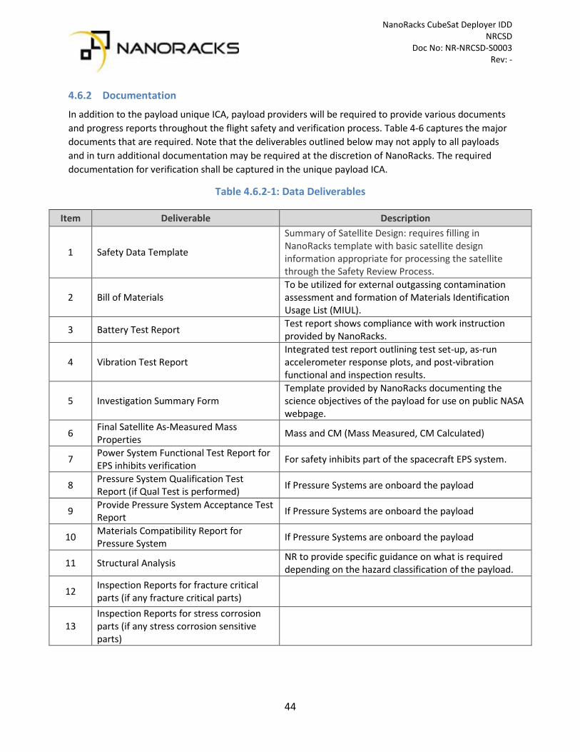
4.6.2 Documentation
In addition to the payload unique ICA, payload providers will be required to provide various documents and progress reports throughout the flight safety and verification process. Table 4-6 captures the major documents that are required. Note that the deliverables outlined below may not apply to all payloads and in turn additional documentation may be required at the discretion of NanoRacks. The required documentation for verification shall be captured in the unique payload ICA.
Table 4.6.2-1: Data Deliverables
Item Deliverable Description
1 Safety Data Template
Summary of Satellite Design: requires filling in NanoRacks template with basic satellite design information appropriate for processing the satellite through the Safety Review Process.
2 Bill of Materials To be utilized for external outgassing contamination assessment and formation of Materials Identification Usage List (MIUL).
3 Battery Test Report Test report shows compliance with work instruction provided by NanoRacks.
4 Vibration Test Report Integrated test report outlining test set-up, as-run accelerometer response plots, and post-vibration functional and inspection results.
5 Investigation Summary Form Template provided by NanoRacks documenting the science objectives of the payload for use on public NASA webpage.
6 Final Satellite As-Measured Mass Properties Mass and CM (Mass Measured, CM Calculated)
7 Power System Functional Test Report for EPS inhibits verification For safety inhibits part of the spacecraft EPS system.
8 Pressure System Qualification Test Report (if Qual Test is performed) If Pressure Systems are onboard the payload
9 Provide Pressure System Acceptance Test Report If Pressure Systems are onboard the payload
10 Materials Compatibility Report for Pressure System If Pressure Systems are onboard the payload
11 Structural Analysis NR to provide specific guidance on what is required depending on the hazard classification of the payload.
12 Inspection Reports for fracture critical parts (if any fracture critical parts)
13 Inspection Reports for stress corrosion parts (if any stress corrosion sensitive parts)

NanoRacks CubeSat Deployer IDD NRCSD Doc No: NR-NRCSD-S0003 Rev: -
45
5 Requirements Matrix
The NRCSD Requirements Matrix assists in validating whether a CubeSat adheres to the specifications outlined in the Interface Definitions Document. Although it contains all relevant sections of the IDD, this matrix is not an official certification of CubeSat compliance with NanoRacks requirements. The Verification Method abbreviations are listed here for reference:
• A: Analysis • I: Inspection • T: Testing
Table 5-1: NanoRacks CubeSat Deployer Requirements Matrix
Paragraph Number
Paragraph Title Requirement Text Verification Method
Submittal Data Type
4.1.1-1 Rail Specification The CubeSat shall have four (4) rails along the Z axis, one per corner of the payload envelope, which allow the payload to slide along the rail interface of the NRCSD as outlined in Figure 4.1-1
I, T Engineering Drawing, Fit Check ROA
4.1.1-2 Rail and Envelope Dimensions
The CubeSat rails and envelope shall adhere to the dimensional specification outlined in Figure 4.1-1
I, T Engineering Drawing, Fit Check ROA
4.1.1-3 Rail Width Each CubeSat rail shall have a minimum width (X and Y faces) of 6mm.
I, T Engineering Drawing, Fit Check ROA
4.1.1-4 Rail Edge Radius The edges of the CubeSat rails shall have a radius of 0.5mm +/- 0.1mm.
I Engineering Drawing
4.1.1-5 CubeSat Load Points The CubeSat +Z rail ends shall be completely bare and have a minimum surface area of 6mm x 6mm.
I Engineering Drawing
4.1.1-6 Rail Design Tolerance The CubeSat rail ends (+/-Z) shall be coplanar with the other rail ends within +/- 0.1mm.
I Engineering Drawing

NanoRacks CubeSat Deployer IDD NRCSD Doc No: NR-NRCSD-S0003 Rev: -
46
4.1.1-7 Rail Length The CubeSat rail length (Z axis) shall be the following (+/-0.1mm): a. 1U rail length: 113.50mm b. 2U rail length: 227.00mm c. 3U rail length: 340.50mm d. 4U rail length: 454.00mm e. 5U rail length: 567.5mm f. 6U rail length: 681 to 740.00mm
I, T Engineering Drawing, Fit Check ROA
4.1.1-8 Rail Continuity The CubeSat rails shall be continuous. No gaps, holes, fasteners, or any other features may be present along the length of the rails (Z-axis) in regions that contact the NRCSD rails.
I Engineering Drawing
4.1.1-9 Rail Envelope The minimum extension of the +/-Z CubeSat rails from the +/-Z CubeSat faces shall be 2mm.
I Engineering Drawing
4.1.1-10 Mechanical Interface The CubeSat rails shall be the only mechanical interface to the NRCSD in all axes (X, Y and Z axes).
I, T Engineering Drawing, Fit Check ROA
4.1.1-11 Rail Hardness The CubeSat rail surfaces that contact the NRCSD guide rails shall have a hardness equal to or greater than hard-anodized aluminum (Rockwell C 65-70).
I Materials List
4.1.1-12 Surface Roughness The CubeSat rails and all load points shall have a surface roughness of less than or equal to 1.6 µm.
I Materials List
4.1.2-1 Mass Limits The CubeSat mass shall be less than the maximum allowable mass for each respective payload form factor per Table 4.1-1
T Integration ROA
4.1.2-2 Center of Mass The CubeSat center of mass (CM) shall be located within the following range relative to the geometric center of the payload. a. X-axis: (+/- 2cm)
I Safety Data Template

NanoRacks CubeSat Deployer IDD NRCSD Doc No: NR-NRCSD-S0003 Rev: -
47
b. Y-axis: (+/- 2cm) c. Z-axis: i. 1U: (+/- 2cm) ii. 2U (+/- 4cm) iii. 3U (+/- 6cm) iv. 4U (+/- 8cm) v. 5U (+/- 10cm) vi. 6U (+/- 12cm)
4.1.3-1 RBF / ABF Access The CubeSat shall have a remove before flight (RBF) feature or an apply before flight (ABF) feature that is physically accessible via the NRCSD access panels on the +Y face of the dispenser.
I, T Engineering Drawing, Fit Check ROA
4.1.4-1 Deployment Switch Requirement
The CubeSat shall have a minimum of three (3) deployment switches that correspond to independent electrical inhibits on the main power system (see section on electrical interfaces).
I, T Electrical Schematic, Fit
Check ROA
4.1.4-2 Plunger Switch Location
Deployment switches of the pusher/plunger variety shall be located on the rail end faces of the CubeSat’s -Z face.
I, T Electrical Schematic, Fit
Check ROA
4.1.4-3 Roller Switch Location
Deployment switches of the roller/lever variety shall be embedded in the CubeSat rails (+/- X or Y faces).
I, T Electrical Schematic, Fit
Check ROA
4.1.4-4 Switch Contact Surface Area
Roller/slider switches shall maintain a minimum of 75% surface area contact with the NRCSD rails (ratio of switch contact to NRCSD guide rail width) along the entire Z axis.
I CAD
4.1.4-5 Switch Reset The CubeSat deployment switches shall reset the payload to the pre-launch state if cycled at any time within the first 30 minutes after the switches close (including but not limited to
I Safety Data Template

NanoRacks CubeSat Deployer IDD NRCSD Doc No: NR-NRCSD-S0003 Rev: -
48
radio frequency transmission and deployable system timers).
4.1.4-6 Switch Captivation The CubeSat deployment switches shall be captive.
I Engineering Drawing
4.1.4-7 Switch Force The force exerted by the deployment switches shall not exceed 3N.
I Switch Datasheet
4.1.4-7 Total Switch Force The total force of all CubeSat deployment switches shall not exceed 9N.
I Switch Datasheet
4.1.5-1 Deployable Systems Restraint
Mechanisms
CubeSat deployable systems (such as solar arrays, antennas, payload booms, etc.) shall have independent restraint mechanisms that do not rely on the NRCSD dispenser.
I, T Safety Data Template, Fit
Check ROA
4.2 Electrical System Interface
Requirements
- - -
4.2.1 Electrical System Design
- - -
4.2.1-1 Power Storage Device Location
All electrical power storage devices shall be internal to the CubeSat.
I Safety Data Template
4.2.1-2 Post-Deployment Timer
CubeSat shall not operate any system (including RF transmitters, deployment mechanisms or otherwise energize the main power system) for a minimum of 30 minutes where hazard potential exists. Satellites shall have a timer (set to a minimum of 30 minutes and require appropriate fault tolerance) before satellite operation or deployment of appendages where hazard potential exists.
I, T Safety Data Template
4.2.1-3 Electrical Inhibits The CubeSat electrical system design shall incorporate a minimum of three (3) independent inhibit switches
I Electrical Schematic

NanoRacks CubeSat Deployer IDD NRCSD Doc No: NR-NRCSD-S0003 Rev: -
49
actuated by physical deployment switches as shown in Figure 4.2-1. The satellite inhibit scheme shall include a ground leg inhibit (switch D3 on Figure 4.2-1) that disconnects the batteries along the power line from the negative terminal to ground.
4.2.1-4 Ground Circuit The CubeSat electrical system design shall not permit the ground charge circuit to energize the satellite systems (load), including flight computer (see Figure 4.2-1). This restriction applies to all charging methods.
I Electrical Schematic
4.2.1-5 RBF / ABF Requirement
The CubeSat shall have a remove before flight (RBF) feature or an apply before flight (ABF) feature that keeps the satellite in an unpowered state throughout the ground handling and integration process into the NRCSD.
I, T Electrical Schematic, Fit
Check ROA
4.2.1-6 RBF / ABF Functionality
The RBF /ABF feature shall preclude any power from any source operating any satellite functions except for pre-integration battery charging.
I Electrical Schematic
4.2.1-7 Wire Requirement The CubeSat Electronics Power System (EPS) shall have no more than six (6) inches of wire 26AWG or larger between the power source (i.e. battery pack) and the first electrical inhibit (MOSFET or equivalent).
I Safety Data Template
4.3.2-1 Random Vibration Environment
The CubeSat shall be capable of withstanding the random vibration environment for flight with appropriate safety margin as outlined in Section 4.3.2.1.
T Vibration Test Report
4.3.5 Integrated Loads Environment
The CubeSat shall be capable of withstanding a force 1200N across all load points equally in the Z direction.
I Safety Data Template

NanoRacks CubeSat Deployer IDD NRCSD Doc No: NR-NRCSD-S0003 Rev: -
50
4.3.8 Airlock Depressurization
The CubeSat shall be capable of withstanding the pressure extremes and depressurization / pressurization rate of the airlock as defined in Section 4.3.8
I Safety Data Template
4.4.6-1 CubeSat Sub-Deployables
CubeSats shall not have detachable parts during launch or normal mission operations. Any exceptions will be coordinated with NanoRacks and documented in the unique payload ICA.
I Safety Data Template
4.4.6-2 Space Debris Compliance
CubeSats shall comply with NASA space debris mitigation guidelines as documented in NASA Technical Standard NASA-STD-8719.14A.
A ODAR
4.4.7.3 Battery Testing All flight cells and battery packs shall be subjected to an approved set of acceptance screening tests to ensure the cells will perform in the required load and environment without leakage or failure. While the specific test procedures vary depending on the type of battery, the majority of Lithium ion or Lithium polymer cells / batteries used in CubeSats can be tested to a standard statement of work issued by NanoRacks (NR-SRD-139).
T Battery Test Report
4.4.7.4 Internal Short Circuit Protection circuity and safety features shall be implemented at the cell level to prevent an internal short circuit.
I Electrical Schematic
4.4.7.5 External Short Circuit Protection circuity and safety features shall be implemented at the cell level to prevent an external short circuit.
I Electrical Schematic
4.4.7.6 Overvoltage & Undervoltage
Protection
Protection circuitry and safety features shall be implemented at the cell level to prevent overvoltage or undervoltage conditions of the cell.
I, T Electrical Schematic,
Battery Test Report
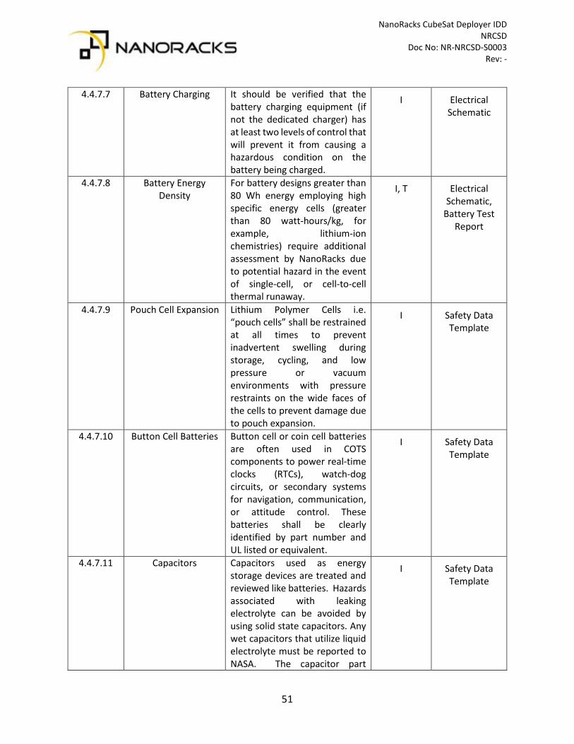
NanoRacks CubeSat Deployer IDD NRCSD Doc No: NR-NRCSD-S0003 Rev: -
51
4.4.7.7 Battery Charging It should be verified that the battery charging equipment (if not the dedicated charger) has at least two levels of control that will prevent it from causing a hazardous condition on the battery being charged.
I Electrical Schematic
4.4.7.8 Battery Energy Density
For battery designs greater than 80 Wh energy employing high specific energy cells (greater than 80 watt-hours/kg, for example, lithium-ion chemistries) require additional assessment by NanoRacks due to potential hazard in the event of single-cell, or cell-to-cell thermal runaway.
I, T Electrical Schematic,
Battery Test Report
4.4.7.9 Pouch Cell Expansion Lithium Polymer Cells i.e. “pouch cells” shall be restrained at all times to prevent inadvertent swelling during storage, cycling, and low pressure or vacuum environments with pressure restraints on the wide faces of the cells to prevent damage due to pouch expansion.
I Safety Data Template
4.4.7.10 Button Cell Batteries Button cell or coin cell batteries are often used in COTS components to power real-time clocks (RTCs), watch-dog circuits, or secondary systems for navigation, communication, or attitude control. These batteries shall be clearly identified by part number and UL listed or equivalent.
I Safety Data Template
4.4.7.11 Capacitors Capacitors used as energy storage devices are treated and reviewed like batteries. Hazards associated with leaking electrolyte can be avoided by using solid state capacitors. Any wet capacitors that utilize liquid electrolyte must be reported to NASA. The capacitor part
I Safety Data Template

NanoRacks CubeSat Deployer IDD NRCSD Doc No: NR-NRCSD-S0003 Rev: -
52
number and electrolyte must be identified along with details of how the capacitor is used and any associated schematics.
4.4.10.1 Stress Corrosion Materials
Stress corrosion resistant materials from Table I of MSFC-SPEC-522 are preferred. Any use of stress corrosion susceptible materials (Table II) shall be coordinated with NanoRacks and documented in the ICA. Any use of Table III materials shall be avoided.
I Bill of Materials
4.4.10.2 Hazardous Materials Satellites shall comply with NASA guidelines for hazardous materials. Beryllium, cadmium, mercury, silver or other materials prohibited by SSP-30233 shall not be used.
I Bill of Materials
4.4.10.3 Outgassing / External Contamination
Satellites shall comply with NASA guidelines for selecting all non-metallic materials based on available outgassing data. Satellites shall not utilize any non-metallic materials with a Total Mass Loss (TML) greater than 1.0 percent or a Collected Volatile Condensable Material (CVCM) value of greater than 0.1 percent.
I Bill of Materials
4.5.2-1 Orbital Debris Mass Requirement
CubeSats over 5kg shall provide an Orbital Debris Assessment Report (ODAR) that verifies compliance with NASA-STD-8719.14.
A ODAR, DAS Input File
4.5.2-2 Re-entry Survivability CubeSats that are designed to survive re-entry or have components that are designed to survive re-entry shall provide an ODAR that verifies compliance with NASA-STD-8719.14.
A ODAR
4.6.1 Regulatory Compliance
The CubeSat developer shall submit evidence of all regulatory compliance for spectrum utilization and remote sensing
I Regulatory Licenses

NanoRacks CubeSat Deployer IDD NRCSD Doc No: NR-NRCSD-S0003 Rev: -
53
platforms prior to handover of the payload. This evidence shall come in the form of the authorization or license grant issued directly from the governing body / agency (which is dependent on the country the CubeSat originates).