GESP-521NASA-CR-72746
is- _ .ij, • _
FINAL REPORT
DEVELOPMENT OF OPTIMUM FABRICATION TECHNIQUESFOR BRAZED Ta/TYPE 316 SS TUBULAR TRANSITION JOINTS
By
S. R. Thompson
J. D. Marble
R. A. Ekvall
Apprcved
E. E. Hoffrnan
prepared for
NATIONAL AERONAUTICS AND SPACE ADMINISTRATION
NASA Lewis ResearchCenter
Contract NAS 3-11846
Phillip Stone, Project ManagGrMaterials and Structures Division
NUCLEAR SYSTEMS PROGRAMS
SPACE SYSTEm
6ENflIALe ELECTRICCINCINNATI, OHiO 46215
N71- 15588
/;//_.... ....._@; .....,_CL).£).-.FA.2,_)
_j ,_AtACRO, _, ",,A',._ " _ , _C ",
1971006113
GESP-521
FINAL REPORT
DEVELOPMENT OF OPTIML_ FABRICATION TECHNIQUES
FOR BRAZED Ta/TYPE 316 SS TUBULAR TRANSITION JOINTS
By
S R. ThompsonF
•J. D. Marble
R. A. Ekvall
Approved iE. E. Hoffman
NUCLEAR SYSTEMS PROGRAMS
SPACE SYSTEMS
GENERAL ELECTRIC COMPANY
Cincinnati, Ohio 45215
Prepared forNATIONAL AERONAUTICS AND SPACE ADMINISTRATION
CONTRACT NAS 3-11846
NASA Lewis Research Center
Cleveland, Ohio
Phillip Stone, Project Manager
Materials and S':ruetures Division
1971006113-002
t
ABSTRACT
Optimum techniques were developed for the brazing and ultrasonic
inspection of tantalum/Type 316 stainless steel, tongue-in-groove design,
tubular transition joints. Experiments were conducted_ which established
those brazing conditions most conducive toward elimination of braze
microshrinkage in the joint areas. Ultrasonic inspection methods were
developed for measuring the quality of the brazed joints. Twelve
2-inch-OD joints for subsequent evaluation testing and usage in the
_AP-8 Power Conversion System were brazed and found satisfactory by
implementation of the developed ultrasonic method of inspection.
r
ii
1971006113-003

SUMMARY
The primary objectives of this program were to develJp optimum tech-
niques for the brazing of tantalum/Type 316 stainless steel, tongue-in-
groove design, tubular transition joints and to generate a reliable
ultrasonic inspection method for determining the quality of such assemblies.
An additional requirement was that twelve 2-1nch-OD x 0.120-inch-wall
production joints be fabricated and inspected 3 utilizing those developed
methods, for subsequent evaluation testing. To achieve the initial goals:
several sheet and tubular sample assemblies were vacuum brazed with
a J-8400 brazing alloy, ultrasonically inspected, and destructively
evaluated. Specific parameters, used in sample brazing, were varied I
k
until optimum (minimum braze microshrinkage) conditions were realized.
as determined by ultrasonic and subsequent microstructural examinations.
The parameters studied were steady state and transient temperature
distributlon conditions across the braze area during brazing and subse-
quent cooling cycles, and the basic cooling rates during solidification
of the braze alloy. A wide range in ultrasonic irspection sensitivities
was initially employed to permit selection of the most appropriate limits.
Detailed comparisons of sample microstructural examination data, with
the ultrasonic presentations for a particular joint, established the
degree of correlation and identified meaningful ultras_nic sensitivity
levels for further inspections.
The experimentation revealed that minimum braze microshrinkage
could be achleved by brazing at 2160°F (I182°C)/5 minutes or 2250°F
(1232°C)/I minute and cooling at a rate of 25°F (14°C)/minute during
braze solidification. Limited testing also indicated that intentional
: solidification of the braze, in a specific selected direction within
. the tongue-and-groove area_ would not substantially improve the brazing
• characteristics. The capability of ultrasonics to accurately depict
_ the brazing characteristics in the bimetallic transition Joints was
demonstrated by correlation of inspection data with physical micro-
structures of three actual prototype Joints. Twelve 2-1nch-OD tubular
iii
1971006113-004
s
production joints were successfully brazed and their quality verified
by ultrasonic inspection. These joints were made available to NASA-LRC
for subsequent evaluation testing or usage in the SNAP-8 Power Conversion
System.
iv
1971006113-005
I
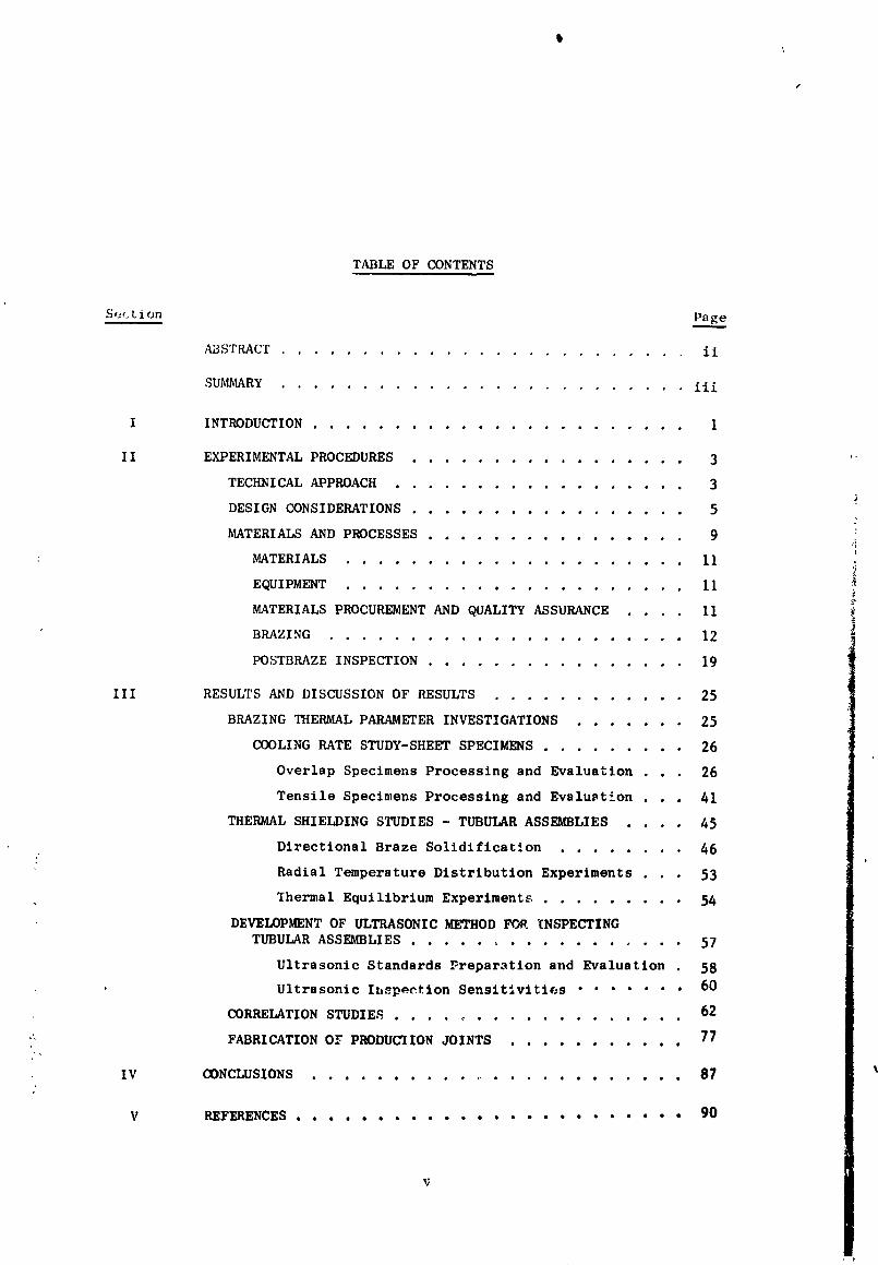
TABLE OF CONTENTS
Se_.tion Page
ABSTRACT ......................... ii
SUMMARY ......................... iii
I INTRODUCTION....................... 1
II EXPERIMENTAL PROCEDURES ................. 3 '
TECHNICAL APPROACH .................. 3
DESIGN CONSIDERATIONS ................. 5
MATERIALS AND PROCESSES ............... 9
MATERIALS ..................... I1
EQUIPMENT ..................... 11
MATERIALS PROCUREMENT AND QUALITY ASSURANCE .... II
BRAZING ...................... 12
POSTBRAZE INSPECTION ................ 19
III RESULTS AND DISCUSSION OF RESULTS .......... 25
BRAZING THERMAL PARAMETER INVESTIGATIONS ...... 25
COOLING RATE STUDY-SHEET SPECIMENS ......... 26
Overlap Specimens Processing and Evaluation . , 26
Tensile Specimens Processing and Evaluation . . . 41
THERMAL SHIELDING STUDIES - TUBULAR ASSEMBLIES .... 45
Directional Braze Solidification ........ 46
Radial Temperature Distribution Experiments . • 53
Thermal Equilibrium Experiments ......... 54
DEVELOPMENT OF ULTRASONIC METHOD FOR INSPECTING
TUBULAR ASSEMBLIES ................. 57
Ultrasonic Standards Preparation and Evaluation 58
Ultrasonic Ihspection Sensitivities ....... 60
62CORRELATION STUDIES ...................
77FABRICATION OY PRODUCIION JOINTS ...........;/,
IV CONCLUSIONS ........................ 87
V REFERENCES ........................ 90
1971006113-006
r
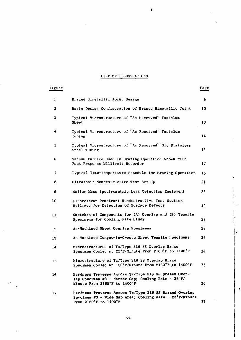
LIST OF ILLUSTRATIONS
Figure Pag____e
1 Brazed Bimetallic Joint Design 6
2 Basic Design Configuration of Brazed Bimetallic Joint I0
3 Typical Microstructure of "As Received" TantalumSheet 13
d Typical Microstructure of "As Received" Tantalum
Tubing 14
5 Typical Microstructure of "As Received" 316 StainlessSteel Tubing 15
6 Vacuum Furnace Used in Brazing Operation Shown With
Fast Response Millivolt Recorder 17
7 Typical Time-Temperature Schedule for Brazing Operation 18
8 Ultrasonic Nondestructive Test Set-Up 21
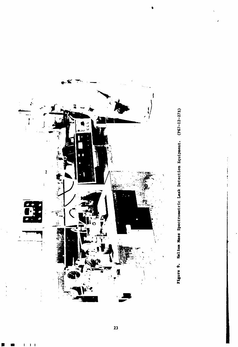
9 Helium Mass Spectrometric Leak Detection Equipment 23
lO Fluorescent Penetrant Nondestructive Test Station
Utilized for Detection of Surface Defects 24
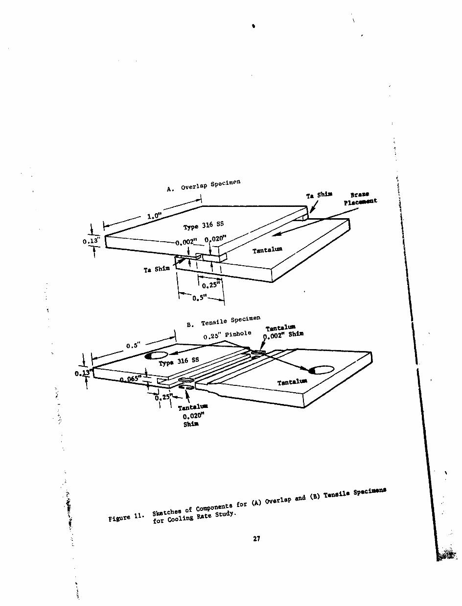
11 Sketches of Components for (A) Overlap and (B) Tensile
Specimens for Cooling Rate Study 27
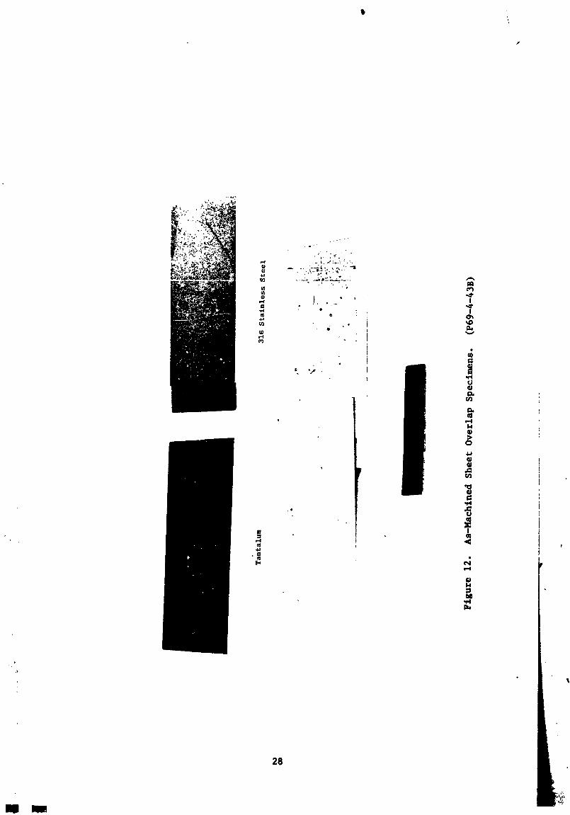
12 As-Machined Sheet Overlap Specimens 28
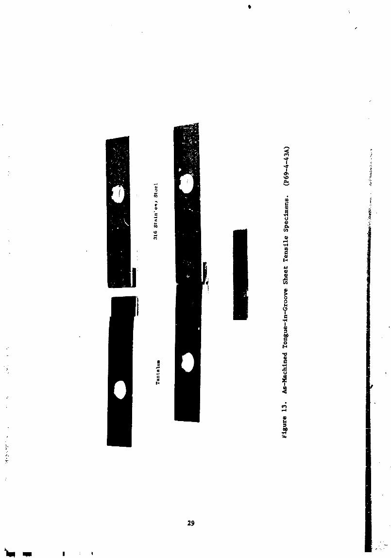
13 As-Machined Tongue-ln-Groove Sheet Tensile _;pecimens 29
14 Microstructures of Ta/Type 316 SS Overlap Braze
Specimen Cooled at 25°F/Minute From 2160°F to 1400°F 34
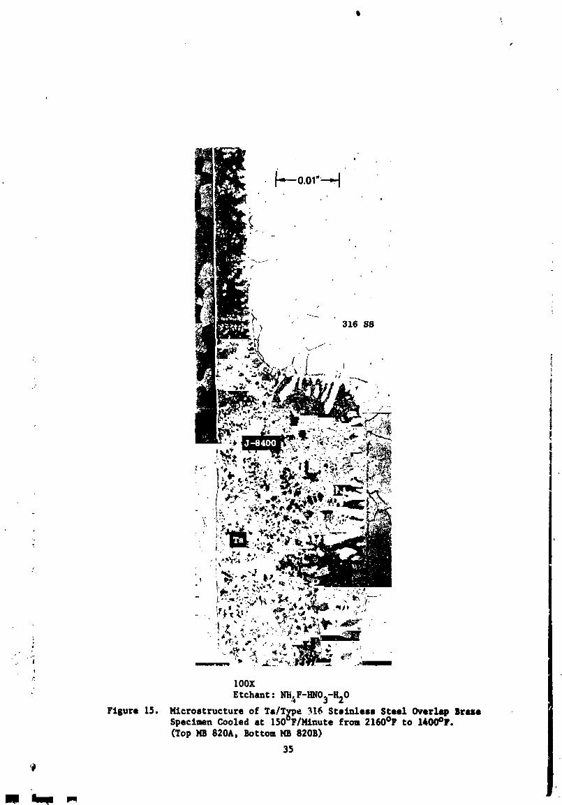
15 Microstructure of Ta/Type 316 SS Overlap Braze
Specimen Cooled at 150°F/Minute From 2160°F.to 1400°F 35
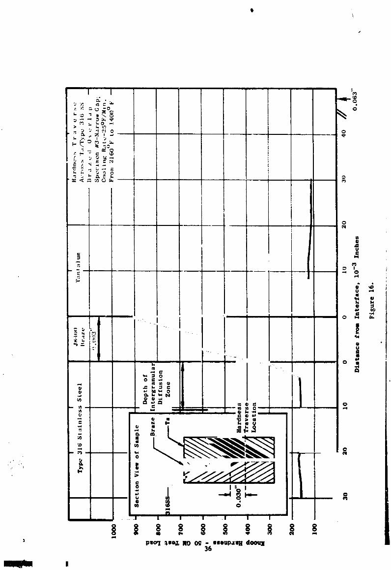
16 Hardness Traverse Across Ta/Type 316 SS Brazed Over-
lap Specimen #3 - Narrow Gap; Cooling Rate - 25°F/Minute From 2160°F to 1400_F 36
l
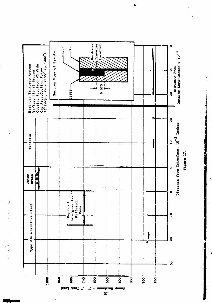
17 Ha_-,tness Traverse Across Ta/Type 316 SS Brazed Overlap
Specimen #3 - Wide Gap Area; Cooling Rate - 25°F/MinuteFrom 2160°F to 1400°F 37
vi
1971006113-007
I,IST OF ILI,USTRA'PIONS
Figure Pag_e
18 Hardness Traverse Across Ta/Type 316 SS Brazed Over-
lap Speclmen #2 - Narrow Gap Area; Cooling Rate -150°F/Minute From 2160°F to 1400°F 38
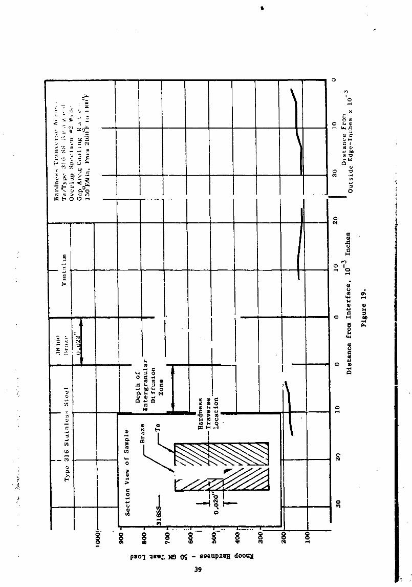
19 Hardness Traverse Across Ta/Type 316 SS Brazed Over-
lap Specimen #2 - Wide Gap Area_ Cooling Rate - 150°F /Minute From 2160°F to 1400°F 39
20 Thermocouple Positions for Directional Sol_dification
Test 48
21 Thermocouple Positions for Thermal EquilibriumTest 55
I22 Sketch of Ta/Type 316 SS Tubular, Tongue-in-Groove
Brazed Joint Used as Ultrasonic Calibration Standard 59
23 Sketch of Transverse Section of Intentionally Misbrazed
Ta/Type 316 SS Tubular_ Tongue-in-Groove Joint Showing
Areas of Brazing. Assembly Used as Ultrasonic Standard 61
24 Typical Ultrasonic "Modified A Scan" Presentations
Attained From Inspection of Transverse Planes Through
the Tongue-in-Groove Brazed Area of Correlation StudyJoint S/N 12 63
25 Unetched Photomicrographs From Correlation Study Joint
S/N 12 at 0.160" Transverse Plane of Inspection. Cir-
cumferential Position 245 ° Rotation From Arbitrary Index.
(Refer to Figure 24.) Note Inner Braze Defect. 68
26 Unetched Photomicrographs From Correlation Study Joint
S/N 12 at 0.160" Transverse Plane of Inspection_ Cir-
cumferential Position 270 ° Rotation From Arbitrary
Index. (Refer to Figure 24.) Defect Free Area. 69
27 Unetched Photomicrographs From Correlation Study Joint
S/N 12 st 0.160" Transverse Plane of Inspection. Cir-
cumferential Position 315 ° Rotation From Arbitrary
Index. (Refer to Figure 24.) Note Outer Braze Defects. 70
28 Typical Microstructures Present at Inner and Outer Braze
Annuli _f Correlation Study Joints S/N 5 and S/N 12. 72
vii
1971006113-008
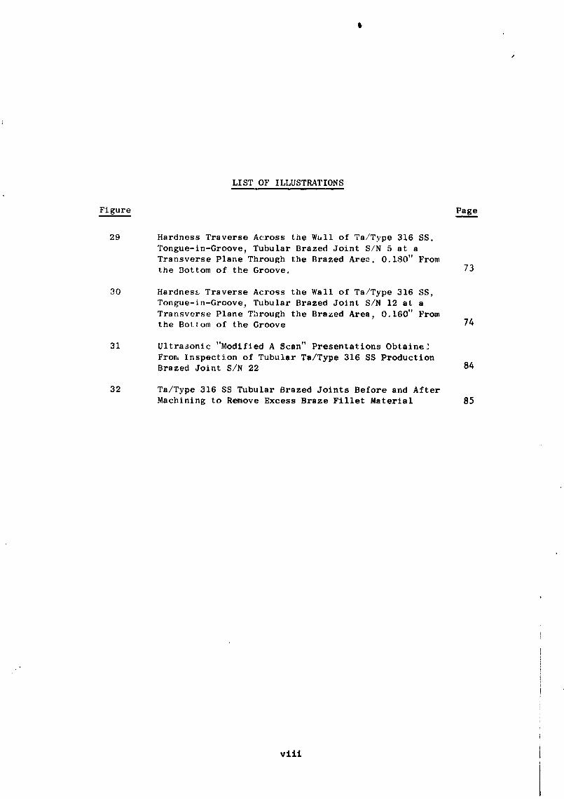
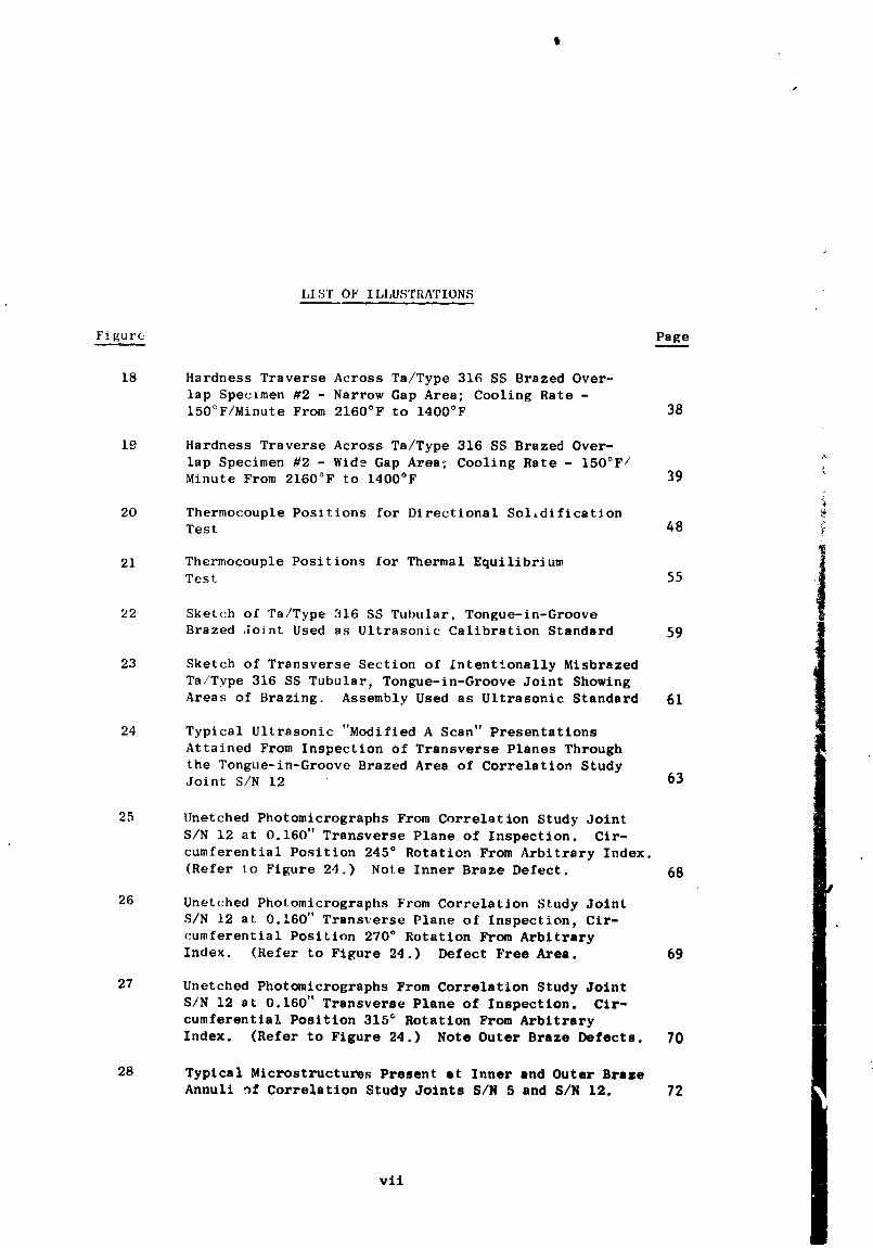
LIST OF ILLUSTRATIONS
Figure Pag___e
29 Hardness Traverse Across the Wull of Ta/Type 316 SS.
Tongue-ln-Groove, Tubular Brazed Joint S/N 5 at aTransverse Plane Through the Brazed Area, 0.180" From
the Bottom of the Groove. 73
30 Hardness Traverse Across the Wall of Ta/Type 316 SS,Tongue-in-Groove, Tubular Brazed Joint S/N 12 at a
Transverse Plane Through the Brazed Area_ 0.160" Fromthe Bottom of the Groove 74
31 Ultrasonic "Modified A Scan" Presentations Obtaine]
From Inspection of Tubular Ta/Type 316 SS ProductionBrazed Joint S/N 22 84
32 Ta/Type 316 SS Tubular Brazed Joints Before and AfterMachining to Remove Excess Braze Fillet Material 85
viii
1971006113-009
LIST OF TABLES
Tabl...___e Pag..__e
I Results of Elevated Temperature Vacuum Tensile
Testing of Initial Tongue-In-Groove Tantalum/
Type 316 Stainless Steel Sheet Brazed Joint
(Specimen #5) 42
II Results of 2000°F Vacuum Tensile Testing of
Tongue-In-Groove T_ntalum/Type 316 StainlessSteel Sheet Brazed Joints 4&
III Results of Thermal Testing to Explore Possible _Directional Solidification in Tantalum/Type 316
: Stainless Steel Tubular (2-Inch OD) Tongue-In-Groov,,-
Joints 50IV Conditions Used in the Vacuum Brazing of Teni_lum/
' Type 316 Stainless Steel Tubular Brazed ,'o±nt_ 79
t
m_
ix
1971006113-010
I. INTRODUCTIONi
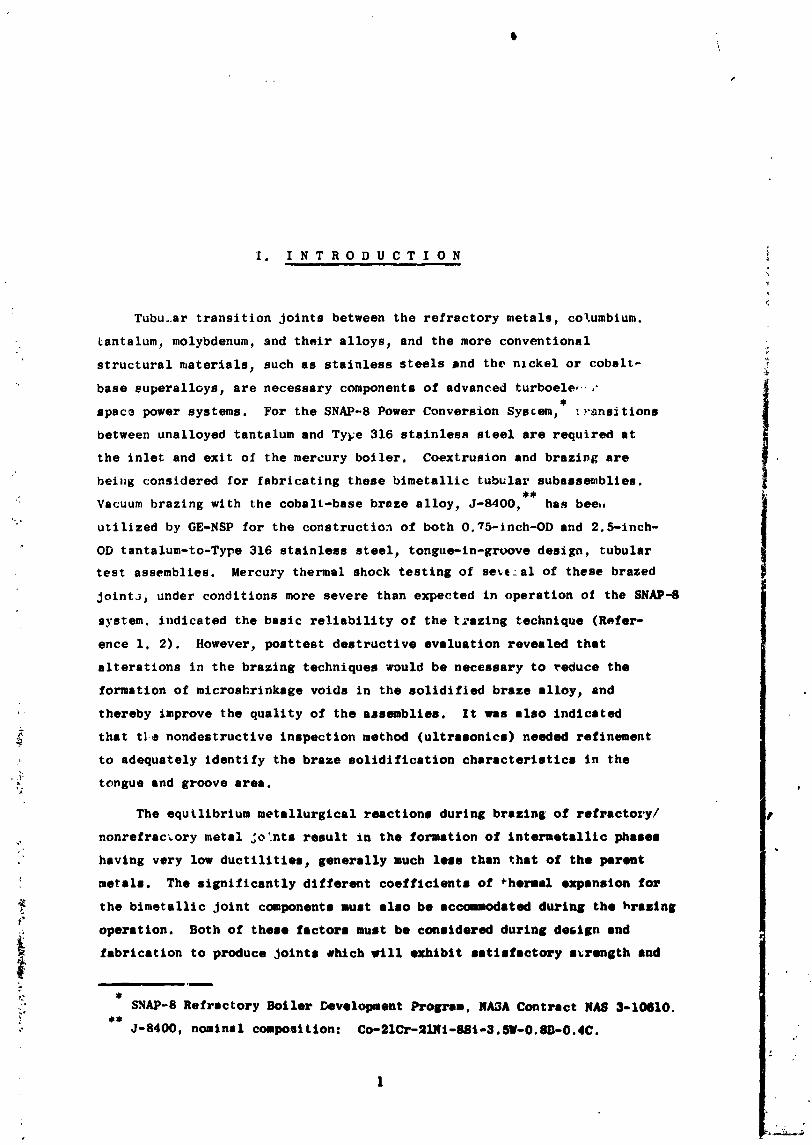
Tubu..ar transition joints between the refractory metals, co_umblum.
Lantslum, molybdenum, and their alloys, and the more conventional
structural materials, such as stainless steels jnd the nickel or cobalt-
base superalloys, are necessary components of advanced turboele,,_-
space power systems. For the SNAP-8 Power Conversion System, tr_nsitions
between unalloyed tantalum and Ty_e 316 stainless steel are required at
the inlet and exit of the mercury boiler. Coextrusion and brazing are
beiJ_g considered for fabricating these bimetallic tubular subassemblies.
t Vacuum brazing with the cobalt-base braze alloy, J-8400, has bee.
utilized by GE-NSP for the construction of both 0.75-1nch-OD and 2.5-inch-
" OD tantalum-to-Type 316 stainless steel, tongue-in-groove design, tubular
test assemblies. Mercury thermal shock testing of se_ al of these brazed
JointJ_ under conditions more severe than expected in operation og the SNAP-8
system, indicated the basic reliability of the t_azing technique (Refer-
ence 1, 2). However, posttest destructive evaluation revealed that
alterations in the brazing techniques would be necessary to reduce the
formation of microahrinkage voids in the solidified braze alloy, and
' thereby improve the quality of the ajaemblles. It was also indicated
that tie nondestructive inspection method (ultrasonics) needed refinement
, to adequately identify the braze solidification characteristics in the
- tongue and groove ares.
The equilibrium metallurgical reactions during brazing of refractory/
nonrefrac_ory metal joints result in the formation of lntermetalltc phases
having very low ductilities, generally much less than that of the parent
metals. The significantly different coefficients of _hermal expansion for
the bimetallic Jolnt components must also be accommodated during the hrsstng
operation. Both of these factors must be considered during design and
i fabrication to produce Joints #lttch will exhibit satisfactory a_rength and
:- SNAP-8 Refractory Boiler Development Prolrram, NA3A Contract NAS 3-10610.
J-8400, nominal composition: Co-21Cr-21Ni-881-3.SW-0.SD-0.4C.
1971006113-011
stability during elevated t_nperature service. The tongue-in-groove
design approach has been successfully utilized to fabricate Cb-IZr/
stainless steel and molybdenum/Haynes' alloy No. 25 brazed tube joints
(Relerence 3). In the majority of those cases, the joint components were
machined such that the tongue members were o£ nonrefractory metal, while
the refractory metal members contained grooves. The previously tested SNAP-8
type bimetallic joints were prepared in that manner with the stainless steel
and tantalum being the tongue end groove_ respectively. Recent theoretical
stress analyses have shown that utilization of the reverse design config-
uration (i.e., refractory metal tongue and stainless steel groove) would
result in assemblies having superior resistance to failure under anti=
cipated SNAP-.8 thermal cycling service exposures (Reference 4). Easier machining
and prebraze component cleaning, and superior braze alloy capillary flow
conditions at the brazing temperature ere other practical aspects which
make that approach more attractive. For these reasons, the tantalum
tongue-stainless steel groove general design configuration was selected
for further investigation in this development program.
The overall purpose of this program was to optimize techniques for
the fabrication of 2-inch OD by 0.12-inch wall brazed tantalum/Type 316
stainless steel tubular transition joints. The initial program objective was to
investigate those variables which influence the braze flow and solidification
characteristics and associated metallurgical reactions. Those factors in-
clude brazing temperature_ time at brazing temperature_ cooling rate during
braze solidification, and the design of component parts to achieve the
desired assembly fit-up characteristics. The data obtained from those
investigations were used to establish the best fabrication techniques.
A further purpose of this study was to develop a reliable ultrasonic
technique for the postbraze nondestructive inspection of the tantalum/
stainless steel joints to assure their quality. Subsequent to the
investigation and development of the brazing and inspection methods, twelve.
2-inch OD by 0.12-inch wall assemblies were manufactured utilizing the
, optimized techniques. These joints were prepared for use in the boiler
of the SNAP-8 Power Conversion System and for additional evaluation testing
which will assist in establishing the acceptance criteria for tantalum/
stainless steel brazed transition joints.
2
1971006113-012
t
II. E X P E R I M E N T A L P R O C E D U R E S
i i,m, ..
TECHNICAL APPROAC_
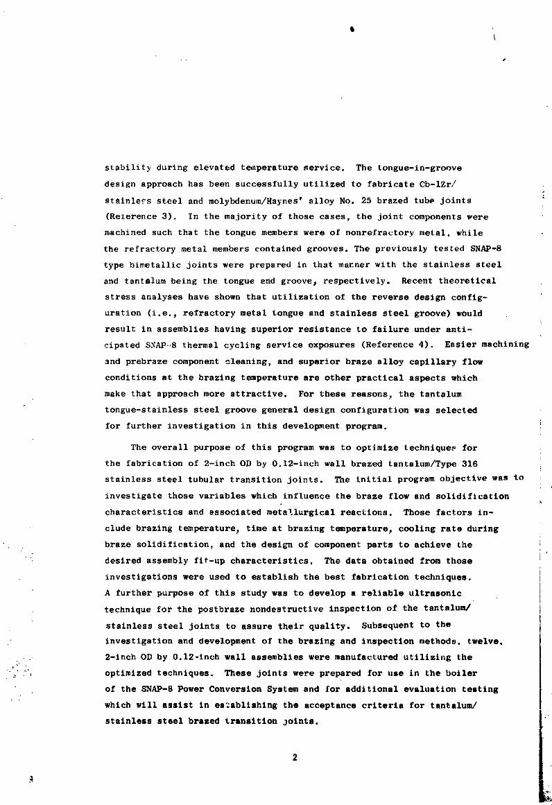
JThe tantalum/Type 316 stainless steel braze optimization study was
conducted in three general phases; i.e._ Brazing Thermal Parameter Studies, J
Correlation Studies, and Production Joint Fabrication.
Some of the specific objectives of the brazing thermal parameter
studies were to establish (I) the cooling rate during solidification of
the J-8400 braze alloy, which minimized microshrinkage void formation;
(2) possible effects of microshrlnkage voids on representative brazed
•' joints tensile properties; (3) the possibility of directional braze
solidification for reducing void formation; and (4) the effects of heat
shielding and associated tubular joint temperature distribution on
minimizing void formation. The results obtained from these determinations
permitted the selection of the best condftlons for fabrication of tantalum/
Type 316 stainless steel tubular brazed joints. An additional goal of the
braze parameter studies was to determine preliminary techniques for ultra-
sonic inspection of brazed bimetallic joints.
_._ The effects of cooling rate variations on the freezing characteristics
'_.. of the J-8400 braze alloy were investigated by the vacuum bra=lt_g of both
_i simple overlap and tongue-ln-groove tantalum/Type 316 stalnless steel sheet
samples. The overlap specimens were individually brazed# using a fixed
heating rate and brazing temperature# and then cooled at several pres_lected
_ rates to provide a range of solidification conditions. Mlcrostructural
examination of the overlap samples was employed to establish the rate which
resulted in the least microshrinkage void formation. Several tongue-in-groove sheet specimens were then produced. These specimens were tensile
tested at elevated temperatures to determine the effect of different cool-'_ ing rates on the joint properties. In addition# several tubular assemblies
_ were brazed_ using different thermal shielding and a fixed cooling rate# to
determine which shielding condition produced the best Joint properties#
as identified by ultrasonic inspection.
3
1971006113-013

\
The potential capability of directional braze solidification for
reducing the extent of microshrlnkage void formation in tubular tongue-
in-groove joints was explored by the vacuum brazing of two assemblies
under conditions expected to be conducive for producing that effect. The
basic technique utilized involved positioning of heat shielding around
the tantalum joint components to reduce radiant heat losses from those
members during cooling from the brazing temperature. The variables.
systematically evaluated before preparation of the indicated joints,
included number and position of heat shields_ geometry of heat shields,
position of the joint in the vacuum furnace, and the overall assembly
cooling rate.
The development of a reliable ultrasonic inspection technique for
the postbraze nondestructive inspection of the tubular braze joints was
implemented by the preparation of suitable inspection standards and the
subsequent inspection of representative tubular sample assemblies. These
sample assemblies were metallographically examined in detail to provide
comparison data of the physical mlcrostructures and the corresponding
ultrasonic presentations obtained from a nominally selected area. These
data wer: used to define the nature of th_ ultrasonic indications and
thereby establish meaningful sensitlvltes for Inspection of subsequent
brazed joints. Particular emphasis was placed on demonstrating that
the ultrasonic method could accurately identify significant structural
defects 3 such as braze poroslty_ cracks or separations in the assemblles_ !
and areas of complete nonbondlng between the braze and parent metalsj
as well as indicating the exact position and relative size of a given
defect. Microhardness traverse testing was performed on all metallographlc
planes of examination to assist in the identification of braze-base metal
metallurgical reactions.
The production Joint fabrication phase of the investigation consisted
: " of first selecting the optimum procedures based on the results generated
in the previous parameter studies, Twelve tubular Joints were fabricated t
by those procedures and subsequently inspected using the developed
4
1971006113-014
ultrasonic technique to assure their i_ternal quality. Other nondestructive
inspection tools_ such as helium mass spectrometric leak testing and dye
penetrant inspection, were also employed to assure the integrity of the z
assemblies.
A tantalum tongue-stainless steal groove design configuration was
utilized for all tubular assemblies construction. Practical design
considerations were the thermal expansion mismatch between the parent
metals, the length of the tongue and groove to provide desired shear
load support areas, and the rvqt,ired overull configuration of the
resultant brazed assemblies. The determination of the radial tongue
and groove dimensions was based on (I) the difference in expansion
of tantalum and Type 316 stainless steel on heating and cooling from',:,
an initially selected 2160°F (I182°C) brazing temperature, and (2) a
_ desired capillary flow spacing at the inside of the tongue and groove
': (radial clearance) at 2160°F (I182°C) of 0.002 inch to 0.003 inch.
Reduction of that spacing during later program joint fabrication was
realized by increasing the brazing temperature.
": DESIGN CONSIDERATIONS
:- The mean coefficients of thermal expansion for tantalum and Type 316
4. i0_ 6:+ stainless steel are _ = 3.6 x in/in/°F (6.5 x 10⁻⁶ cm/cm/°C) and
"_ 10.5 x 10⁻⁶ in/In/°F (2.0 x 10-`5 cm/cm/°C)3 respectively. A primary function
:_ of the design of tubular transition joints between those materials is to
accommodate that relatively large difference in expansion during heating
• and/or cooling between ambient and elevated temperatures. One configura-
tion that has been shown to be suitable for the preparatlon of reliable
transition joints is that of the tongue-in-groove (References I_ 2# and 4).
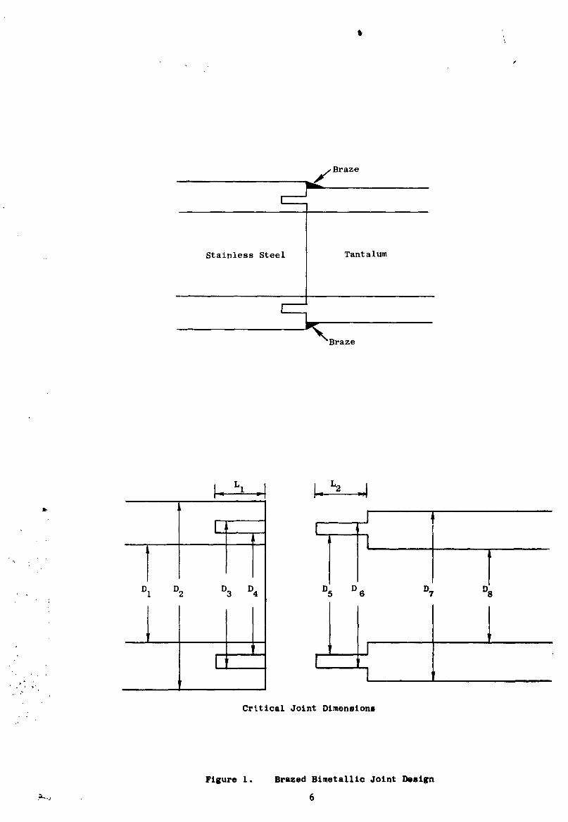
The critical dlmenslons_ pertinent to the tongue-ln-groove geometry_
are presented in Figure 1. The temperatures# utilized in brazing (nominally
-._ 2160°F (1182°C) for J-8400 braze alloy) are necessarily higher t,_an those
:+ which might be encountered in sorvice. Thus I the brazing operation actually
5
+
&
1971006113-015
t
Stainless Steel Tantalum
'TT'Tl"D1 D2 D3 D4 D5 D 6 D7 !
,1!,"' ' I P• i i i
i,
p
Critical Joint Dimensions
Figure 1. Brazed Bimetallic Joint Design
1971006113-016
\
establishes the required interrelated dimensions of the component
parts. The majority of previously fabricated_ _NAP-8 type, tubular
bimetallic brazed assemblies were prepared using a stainless steel
tongue-tantalum groove configuration. Recent theoretical stress
analyses have indicated that a more favorable state of stress would be
associated with the reverse approach for the tantalum/Type 316 stain- i
|less steel materials combination; i.e., tantalum tongue, stainless
steel groove, and that basic design was, therefore, selected for {
i
this optimization study. The following will point out some of the
pertinent design considerations regarding tubular tantalum tongue-
stainless steel groove assemblies (refer to Figure 1).
The necessary spacings, at the brazing temperature, between
the inside and outside of the tongue and groove, are determined
from the following differential expansion equation as applied
to both joint components:
Df = DO (i + _ AT)
where:
Df = tongue or groove diameter at the brazing temperature,
inches;
D = tongue or groove diameter initislly, inches;o
= mean coefficient of thermal expansion for either tantalum or Type
316 stainless steel at the brazing temperature# in/in/°F; and
• LT = Tf - T = temperature change in brazing, °F..._ o?
Referring to the tantalum tongue design, the outside diameters
of the tongue and groove (D 3 and D6) must be machined to the
closest possible fitup at room temperature, since the dif-
ferential expansion on heating to the brazing temperature will
produce a relatively large annular spacing in that ares, which
must be filled by the braze alloy. The difference in the co-
efficients of thermal expansion for tant_l,_m end Type 316 stain-
10-6_, less steel, _ss " OTa' equals approximately 6 x in/in/°F,
Thus, for initially equal diameters_ D3 and D6, of 2.0 inch. the
annular radial clearance at 2160°F (1182°C) would be 0.012 inch.
1971006113-017

Complete filling of that zone by the brazing alloy can be
more readily achieved in joints of the tantalum tongue design,
because it will be immediately adjacenc to the outside joint
surface where the brazing alloy has been preplaced. The
original machined dimensions of the outside tongue and groove
diametric surfaces nominally are selected as equal to one-third
of the joint wall thickness less than the outside diameter of
1 D2 - 1 (.D7 - D8)the assembly; i.e., D3 = D6 = D 2 - _ (....2 DI) = D7 - _ 2 "
Stress analyses have indicated that a tantalus, tongue
thickness, equal to or greater than one-third of the total
wall thickness of that component in the joint area, would
result in an advantageous stress distribution condition, sub-
sequent to the brazing operation. Based on this consideration.
the inside tongue diameter, at machinlng, is established as,
(D 7 - D8D5 = D6 - (0.4) 2 "') (2) = D6 - 0.4 (D7 - D8).
The as-machined dimension at the inside of the stainless
steel groove is determined by (1) application of the previously
indicated expansion equation to both the tongue and groove
inside diameters, and (2) including allowances for achieving
desired braze capillary spacing at the brazing temperature.
Thus, the inside diameter of the tantalum tongue at the brazing
temperature is calculated; i.e., D5 at 2160°F (I182°C) = D 5
original (1 + _Ta AT). The inside groove diameter, D4, atl
temperature is then equal to that tongue diameter, less twice
the desired capillary flow spacing; i.e._ D4 at 2160°F (I182°C) =
D5 at 2160°F (1182°C) - 2 (0.003 inch nominal spacing). The
original groove inside diameter to be machined is then estab-: D4 at 2160°F
. fished; D4 original = i + _ AT "ss
._ The axial tensile strength of tongue-in-groove brazed joints
is dependent _n the braze alloy shear strength and the tensile I
strength of the Joint components. The known low shear strength
of the cast J-8400 braze alloy may be compensated for by .
1971006113-018

increasing the length of the tongue and the depth of the
groove, L2 and LI, respectively in Figure l, which increases
the shear load support area. These dimensions may be increased
to a point where the effective shear area is many times the
cross sectional ares of the joint components. The practical
limitation of this compensation is the distance over which {
the braze alloy must flow during the brazing operation. For
any size tubular joint, increases of the tongue/groove lengths,
in unit multiples of the wall thickness, produce shear areas
which increase by a factor of twice the tube cross section.
Some other comments regarding design configurations are
as follows:
I. The difference between the outside diameters of the
two component parts (D 2 - D7) is usually maintained
at 0.04 - 0.06indh to provide an sre_ for brame
alloy preplacement and exterior braze fillet formation.
2. The edges of components in the tongue end groove area
are rounded to reduce stress concentrations in those areas.
3. The diameters of the stainless steel component, D1 and
D2, may be varied slightly in the joint area, such that
the wall thickness there is greater than at other axial
locations. This action permits increasing of the
_ tantalum tongue thickness to a more suitable dimension.
-,
The preceeding discussion indicates most of the considerations
which were included in the design of the tantalum/Type 316 stainless
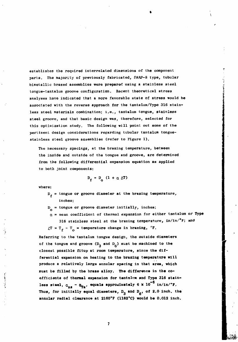
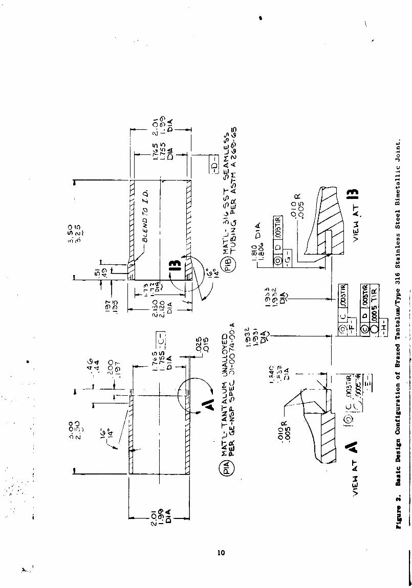
steel tubular joints for this study program. The desired overall
configuration of the bimetallic assemblies was 2-inch OD by O.12-tnch
wall by 6 inches long. The resultant design configuration employed
is presented in Figure 2.
_ MATERIAI_ AND PROCESSES
The materials and equipment utililed in this investigation are
9
,/
1971006113-019
IO
]
1971006113-020
summarized in the followlng tabulation:
MATERIALS
1. Unalloyed tantalum tubing - 2 inch OD by 0.12 inch wall
2. Unalloyed tantalum sheet - 0.130 inch thickness _
3. Type 316 stainless steel tubing - 2. i25 inch OD by 0.188 inch wall i
4. Type 316 stainless steel sheet - 0.130 inch thickness|
5. J-8400 braze alloy in powder form - per GE Specifications BSOT56
and BSOT56-SI
6. Brazing aids - Nicrobraz "Cement" and "Green Stop-off"; both are
commercial products manufactured by the Wall-Colmonoy Colnpsny
7. Reagent grade acetone and ethyl alochol
: 8. Reagent grade acids - HNO3, HF, and H2SO4
,; 9. Deionized snd tap water
i0. Platinum - platinum + I0 percent rhodium thermocouple wire
0.020 inch diameter
EQUIPMENT
1. Vacuum furnace - Richard D. Brew ]nc. Furnace, Model 424B.
2. Vacuum gauges and readout - Fredericks Inc., "Televac" readout
and dual filament ionization gauge.
.. 3. Temperature recorder - Brown Inc. "Electronik", pen line recorder.
"i 4. Potentiometer - Leeds and Northrup Inc._ milltvolt potentiometer.
5. Emf signal amplifier/readout - Sanborn Inc., preamplifier and two
_: channel readout.
6. Helium leek detectors - General Electric Company end National
." Research Corporatiol,, Mass Spectrometers.
7. Ultrasonic inspection gear_ including s Gisplsy/timer, pulser/
receiver, gate, high-frequency search units, facsimile recorderi
: and a centering rotational fixture.
• _
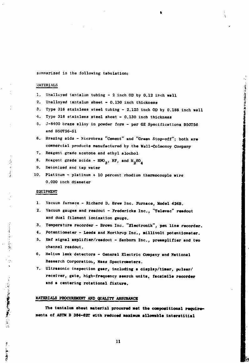
PRoa m rAND. ALXASS CZThe tantalum sheet msteri_l procured met the compositional rsquiM-
g..• merits of ASTM B 364-6_T with reduced maximum sllovlble interstitial
II
1971006113-021
elements content; i.e., oxygen 100 ppm_ nitrogen 75 ppm_ carbon 50 ppm,
and hydrogen 10 ppm. A sample of the as-received tantalum sheet was
examined metallographically end found acceptable; a typical microstructure
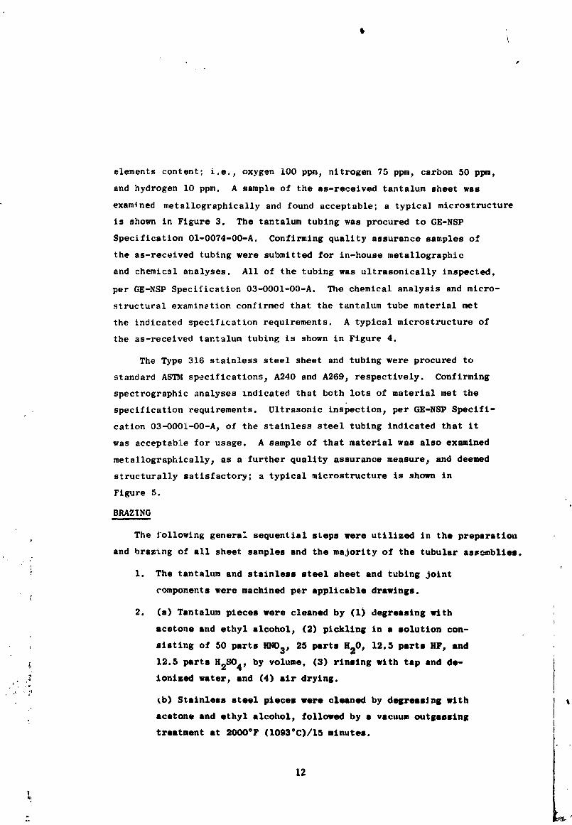
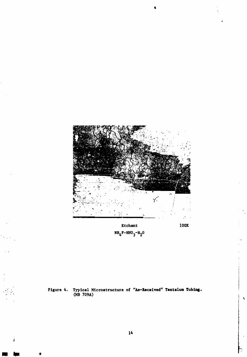
is shown in Figure 3. The tantalum tubing was procured to GE-NSP
Specification 01-0074-00-A. Confirming quality assurance samples of
the as-received tubing were submitted for in-house metallographic
and chemical analyses. All of the tubing was ultrasonically inspected,
per GE-NSP Specification 03-OO01-O0-A. _te chemical analysis and micro-
structural examination confirmed that the tantalum tube material met
the indicated specification requirements. A typical microstructure of
the as-received tantalum tubing is shown in Figure 4.
The Type 316 stainless steel sheet and tubing were procured to
standard ASTM specifications 3 A240 and A269j respectively. Confirming
spectrographic analyses indicated that both lots of material met the
specification requirements. Ultrasonic inspection_ per GE-NSP Specifi-
cation 03-0001-O0-A 3 of the stainless steel tubing indicated that it
was acceptable for usage. A sample of that material was also examined
metallographically 3 as a further quality assurance measure_ and deemed
structurally satisfactory; a typical microstructure is shown in
Figure 5.
BRAZING
The JOllowing genera: sequential steps were utilized in the preparation
end brazing of all sheet samples and the majority of the tubular ass_blies.
1. The tantalum and stainless steel sheet and tubing Joint
components were machined per applicable drawings.
2. (a) Tantalum pieces were cleaned by (1) degreasing with
acetone and ethyl alcohol_ (2) pickling in a solution con-
slstlng of 50 parts HNO3_ 25 parts H20 , 12.5 parts HF, and
12.5 parts H2SO4, by volume, (3) rinsing with tap and de-
ionized water, and (4) air drying.
tb) Stainless steel pieces were cleaned by degreaaJng with t
acetone and ethyl alcohol, followed by • vacuum outgasaing
treatment at 2000°F (1093°C)/15 minutes.
12
1971006113-022
k
1971006113-023
Itt
• _ _*-_ _ i _ ' •
_" . '.."<, _,-" .:'_- -, "-.- ,_ ., " 1
Etchant IOOX
NIt4F-ItI_03-1t20
,. • Figure 4. Typical Hicrostructure of "As-Received" Tantalum Tubi_..... (lib 709A)
't
14
R m
1971006113-024
i
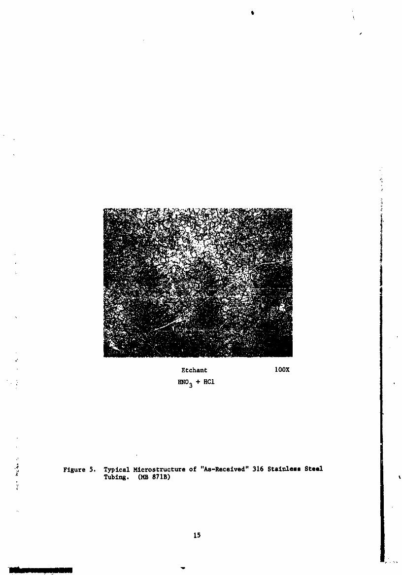
Etchant 100X
HNO 5 + HC1
._ Figure 5. Typical I_Lcrostructure of "As-Received" 316 Stainless SteelTublng. (MB 871B)
a
t-
15
1971006113-025
\
I
3. Components were assembled for brazing, using clean, lint-free
nylon gloves (tantalum shim stock was used to n,aintain desired
brazing tolerances for the sheet brazed samples).
4. Powdered braze alloy was applied as a slurry to the joint areas
of all assemblies, using "Nicrobraz Cement" as a binder/carrier.
After waiting a minimum of two hours, to allow initial volatili-
zation of the binder to occur, the joints were ready for brazing.
"Stop-off" was applied to the joint surfaces, adjacent to the
brazed areas, to prevent braze runoff.
5. Thermocouples (Pt-Pt „�´�p�Rhwires and A1203 insulators) for
temperature measurement_ were resistance tack welded to exposed
tantalum and stainless steel surfaces at selected locations.
Individual wires were attached at their ends onlyj thereby pro-
ducing junction thermocouples. Tantalum foil (O.002-inch
thickness) was positioned around the thermocouples_ not touching
the wiresj to avoid potential incorrect temperature readings
caused by: (1) a change in chemistry of the thermocouple wires
as a result of evaporation and subsequent alloying of volatile
braze constituents with the thermocouple wire material; and
(2) a "fin cooling" effect at the wires between the tack welded
junctions and the nearest A1203 insulator.
6. The instrumented assemblies were positioned in the vacuum
furnacej shown in Figure 63 which was then evacuated to a
pressure of less than 5 x 10 -5 torr before starting the brazing '
heatup cycles. The tubular Joints were brazed in a vertical
position with the stainless steel member on the bottom. Thermal
heat shielding was positioned 3 as necessary_ around the Joint
assemblies and at furnace ports.
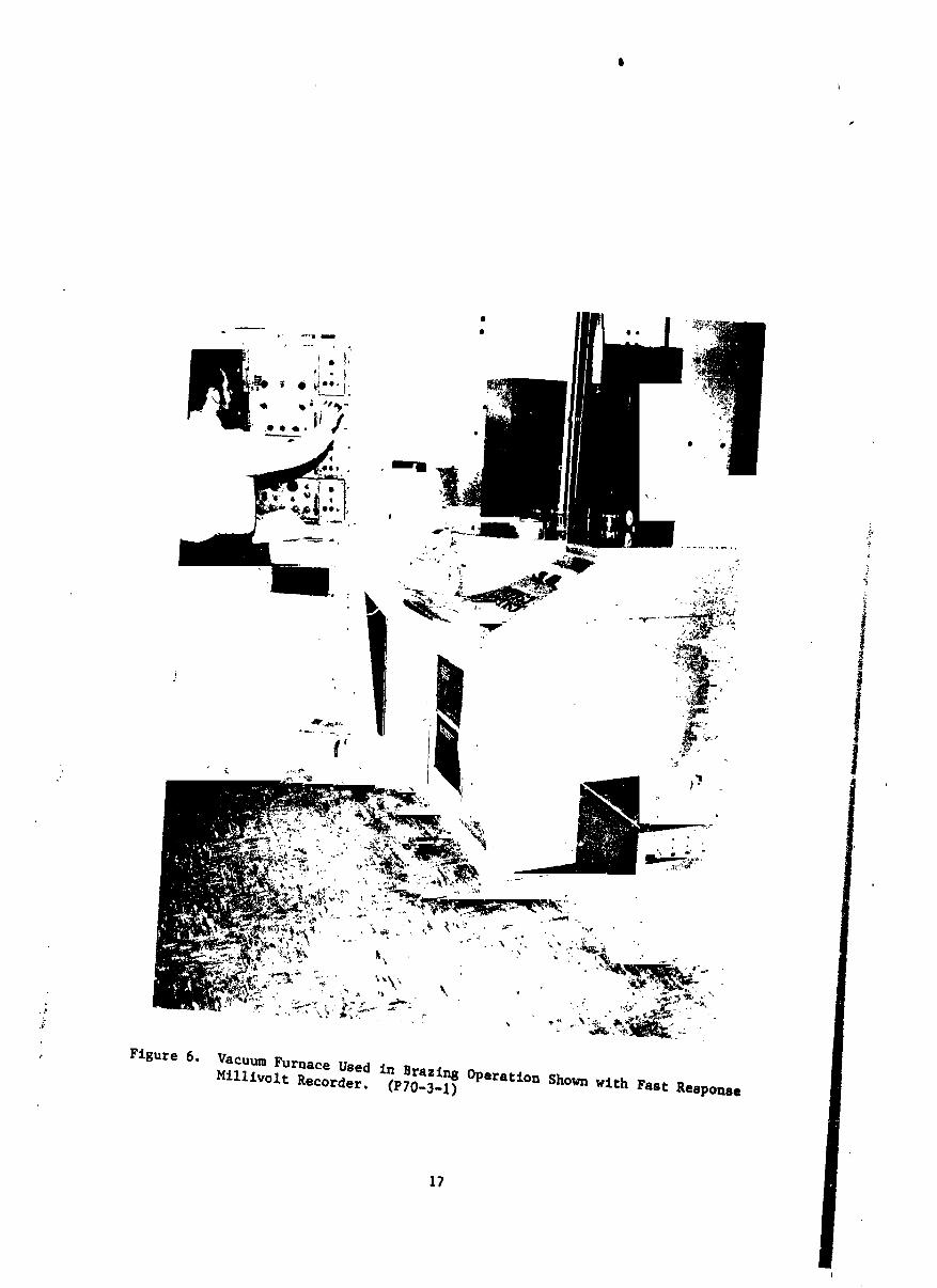
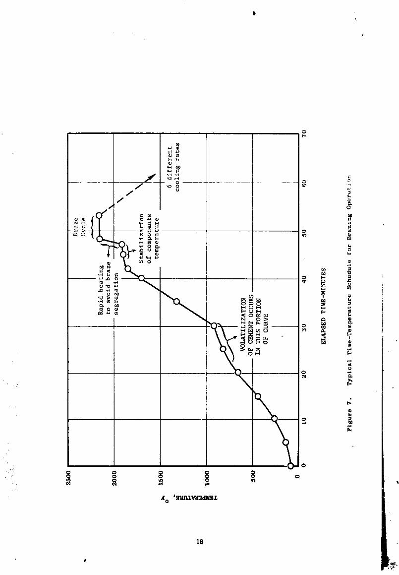
7. The assemblies were heated to selected brazing t_mperatures in
,_ accordance with the time-temperature schedule presented inFigure 7. The beating cycle consisted of five pertinent zonea_
i.e., (1) heating to 800°F (427°C) at a rele_ively slow rate
(approximately 50°F (27°C/minute)_ to prevent "spelling off"
of the applied braze powder, (2) holding at 800°F (427°C) to
16
1971006113-026
1,
l
, Flgure 6. MllllvoltVacuumFurnaceRecorder.USedin(P70.3.1)Brazln80peratlonShown wlth Fast Response
t7
i
/
1971006113-027
\
t8
1971006113-028
allow complete volatilization of the binder to occur_ (3) heating
at a nominal rate (approximately 70°F (39°C)/minute) to a
temperature slightly below the solidus temperature of the J-8400
braze alloy - 1925°F (I052°C), (4) holding at 1925°F (I052°C) to
allow stabilization of component temperatures, and (5) rapid
heating (approximately 250°F (139°C)/minute) to the brazing
temperature to prevent segregation and nonuniform melting of
the braze alloy.
8. The assemblies were held at the brazing temperature for a
sufficient tim_, before cooling, to allow the brazing alloy
to flow and fill the tongue-in-groove annular braze cavities.
9. The assemblies were cooled iv vacuum_ from the brazing tempera=
ture to 1400°F (760°C) at a predetermined rate_ during which
time the braze alloy selidlfled.
10. The assemblies were then cooled at a nominal furnace cooling
rate to room temperature_ and the thermocouples removed. Residue1
"stop-off" material was then removed from external joint surface
by wire brushing.
11. All assemblies were thereafter ready for inspection and evaluation.
" The outside braze fillet surfaces of the production joints were
machined, after nondestructive testing, to remove excess braze
:- materials from those areas
_The same general technique was employed in the brazing of tubular
, joints for the directional solidification study with the exceptions of
the locations of the instrumentation thermocouples, and the number and
_ocation of the thermal shields employed.
POSTBRAZE INSPECTION
After brazing of tubular Joint_ aeveral nondestructive inspection
._ technt¢_01es were employed to determine Joint quality. Ultrasonic ln-
•_ spection was the inspection tool of predominant importance used for
evaluating joint acceptability.
4
19
1971006113-029
\
The ultrasonic equipment used in this investigation consisted of
(1) a standard display unit with a special broadband pulser-receiver
and a rapid gating syste_ fc_ separate recording of the braze annuli
at the inside and outside of the tongue and groove of tubular assemblies.
(2) a special transducer, and (3) a rotational fixture which allows both
incremental indexing for "C-scan" recording (plan view) and continuous
rotation for modified "A-scan" (X-Y) recording. A general ultrasonic test
setup is shown in Figure 8. The procedure for attaining "C-scan" recordings
of the sheet and tubular tongue-in-groove brazed joints was as follows:
I. The gate was set electronically to isolate one of the braze
regions (inside or outside of the tongue and groove).
2. The joint area was scanned axially by a back and forth movement
of the pulser-receiver _eep unit.
3. The back and forth motion was repeated after circumferential
or transverse indexing to reposition the sweep unit 0.004 inch
away from the previous scan position.
4. The entire joint area of a giveu brazed assembly was inspected
by repeating the indexing-scan_i£ng operations sufficient times.
An indication of a defect appeared as a black area on the "C-scans',
whereas sound-brazed areas appeared white. Different levels of recording
pickoff and different sensitivities of inspection were used to display
specific defect areas. Thus_ defects of all sizes were capable of
being shown on a given "C-scan".
The procedure for achieving modified "A-scan" presentations of the
tubular tongue-in-groove brazed joints was as follows:
I. The transducer was positioned at the axial extremity of the
brazed area.
: 2. The Joint was then rotated under the transducer through 360 °
"' and an X-Y recording made of the relative magnitudes of the
ultrasonic signals generated. Again the ultrasonic gate was
electronically set to isolate the two brazed areas.
2O
! I
1971006113-030
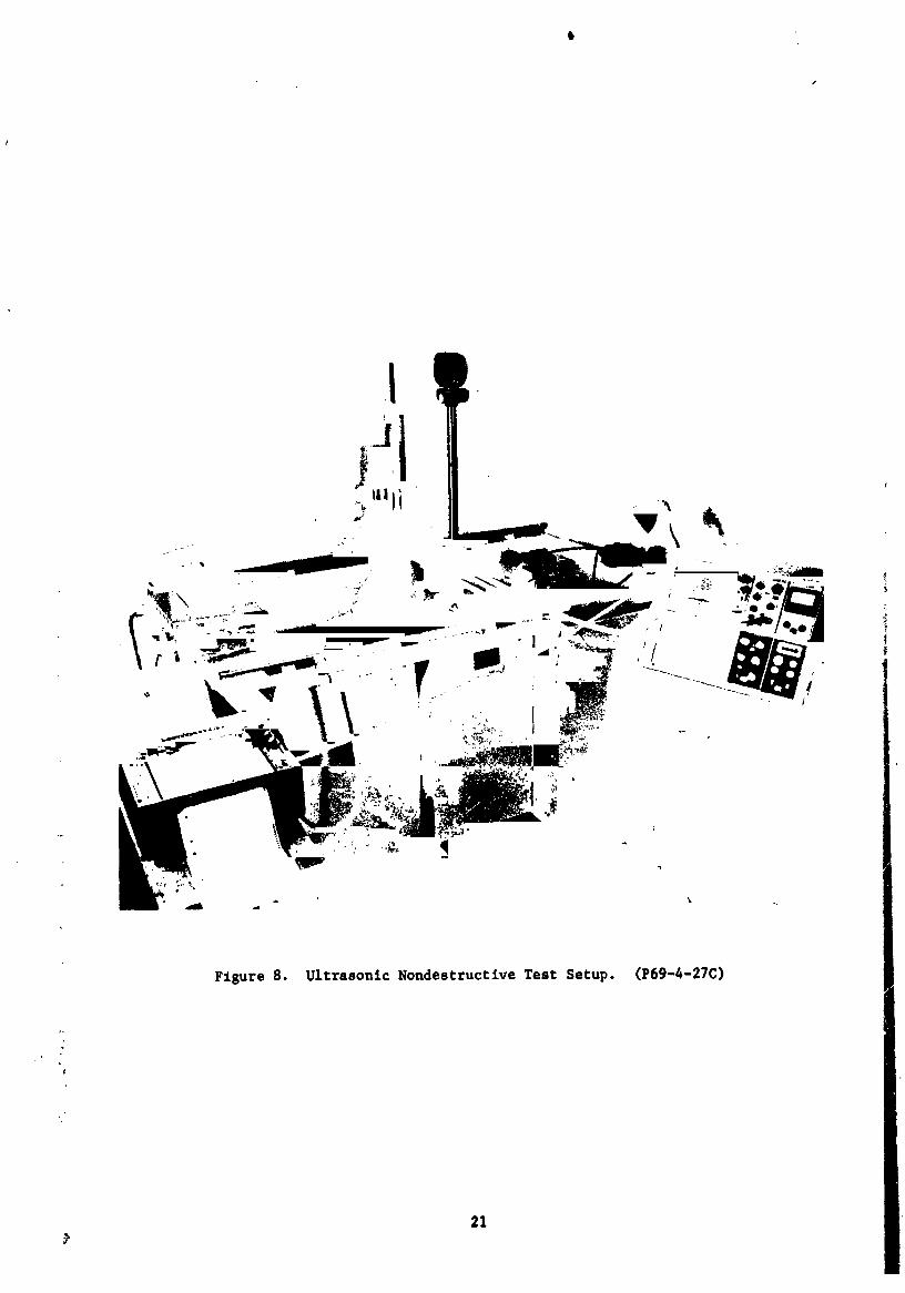
Figure 8. Ultrasonic NondestructiveTest Setup. (P69-4-27C)
¢
21
I
1971006113-031
I
3. After the initial circumferential scan was completed, the
transducer was repositioned 0.010 inch away (axial displacement)?
from the initial transverse plane of inspection and a second
X-Y scan recording obtained.
4. The repositioning-rescanning process was repeated to obtain
inspection data for the entire joint; each plane was separated
from the previous plane by 0.01 inch.
These modified "A-scans" thereby presented the magnitude of ultrasonic
signals versus a specific location in the tubular joints. These scans
were utilized in the correlation study phase of this program and for
production joint inspection, since they covered a wider range of in-
spection sensitivities than those generated in the "C-scan" inspections.
More detailed descriptions oi the ultrasonic techniques and equipment
will be indicated in later paragraphs related to actual samples and/or
production joint inspection.
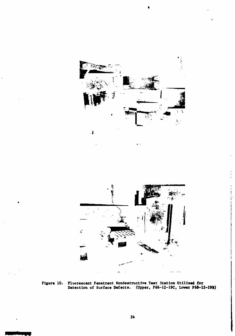
After postbraze ultrasonic inspection and machining of the tubular
production joints had been completed, all were helium leak tested and
dye penetrant inspected as a further check of their quality. Figures 9
and i0 depict the helium leak testing and dye penetrant inspection
facilities used for those operations.
22
Ii
1971006113-032
i
23
I I i i u
197100611 _-0_
$
• L
Fisure 10. Fluorescent Penetrant Nondestructive Test 3tation Utilised forDetection of Surface Defects. (Upper, P66-12-19C, Lover P68-12-19B)
26
I
1971006113-034
III. R E S U L T S A N D D I S C U S S I O Nn
OF RESULTSnln ._
BRAZING THERMAL PARAMETER INVESTIGATIONS
Some of the important factors considered in the preparation of brazed
assemblies include the following: (
1. Melting temperatures of the braze alloys and parent metals.
2. Metallurgical compatibility of the braze alloy with the base
metals _t the brazing and service operating temperatures.
3. Control of the brazing environment to prevent contamination
of the joint constituents and impairment of braze wettability.
4. Metallurgical reactions during the brazing cycle which can
produce detrimental effects on the natule of the braze alloy
solidification.
,. Assembly design configuration to accommodate differences in
components properties.
6. Strength and ductility of fabricated brazements.
Most of these variables, regarding tubular tantalum/Type 316 stainless
steel brazed Joints, have been previously considered in association with
component fabrication for the SNAP-8 Refractory Boiler Development
Program. (1'2) ,_e areas requiring further study in this opttmi_tlo_
program w_,re _oncerned with determining the effects of braze cycle
cooling rate _driattona on the solidification characteristics of the
J-8400 braze alloy and the corresponding stremgth properties of ropre-
sentativ_ brazed assemblies.
Brazing may be equated to a casting process, where the metallic filler
alloy is the material being cas _ , and the components being Joined form
the casting mold. Most metals being c:at contract during solidification;
such i, _so true for the freezing of braze alloys. This contraction or
hmmmm i I
1971006113-035
shrinkage may resul_ during nonequilibrium coolin_ in the formation of
objectionable microshrinkage voids in the last areas of the braze material
to solidify, in casting or brazing, the microshrinkage void formation can
be minimized by using very slow cooling rates during solidification, which
weuld provide sufficient time for necessary equilibrating diffusion to
occur. While an improvement in the braze alloy freezing characteristics
can be realized by slow cooling, potentially adverse reactions in the
base metals would be magnified. Thus_ it is imperative to determine the
cooling rate which produces a minimum amount of braze microshrinkage and
an acceptable amount of braze-base metal interaction in order to Ins_,re
brazed assemblies with optimum overall properties.
COOLING RATE STUDY-SHEET SPECIMENS
: The effects of cooling rate variations on the extent of J-8400 braze
alloy micr)shrinkage and related base metal penetration diffusion
reactions in tantalum/Type 316 stainless steel brazed joints were
investigated to establish optimum conditions. Sheet materials, 0.130-
inch thick, were employed foz this study. Two types of specimens -
simple overlap and tongue-in-groove sheet samples - were used, each
having dimensions in their joint areas which closely approximated
th_se of tongue-_n-groove tubular assemblies. The as-machined configur-
ations of these sheet samples are shown in Figures ll, 12 and 13. _
Overlap Specimens Processing and Evaluation
The initial joints prepared were the overlap type. The tantalum and
stainless steel component parts of these samples were assembled and
vacuum brazed with the J-8400 alloy, using the previously described
tecnniques. Six, 4 t overlap (overlap equals 4X sheet thickness)
specimens were indivicvally brazed at 2160°F f1182°C)/5 minutes and
subsequently cooled to 1400°F (760°C) using 25°F (14°C), 50°F (27°C),
75°F (42°C)_ IO0°F (55°C), 125°F (70°C), and 150°F (84°C) per minute
; _ rates, during which time the braze alloy solidified. Visual examination
i_ _" of the samples, after brazing, indicated good braze flow and wetting
over the entire brazed areas.
The brazed overlap specimens were ultrasonically inspected to
26
| , I
1971006113-036
t
A. Overlap Specimen
...L i._......_-----'- 1,0"F TaS i,. _rsu
Ta Shim
Ta Sh_.m
i
B. Tensile Specimen
0.5" _ 0°25" Pinhole Tantalum
1.002"Sh_ ,
Oo
I
Shtm
_ Figure I1. Sketches of Components for (A) Overlap and (B) Tens:tle Specimms' for Coolius Rate Study.
27
28
m m
1971006113-038
29
l ! ; I
1971006113-039
determine the comparative braze quality of each. Appropriate areas for
metallographic examination were selected from the generated ultrasonic
scans. The areas chosen were representative of the most significant
ultrasonic defect indications for each sample, rather than arbitrary
sections through the brazed areas. This was necessary because a well
defined ultrasonic standard was not available for use during their
inspection. The purpose of the metallographic examination was twofold:
i.e., first, to establish the capability of the ultrasonic inspection
"C-scan" presentations for accurately depicting defects (microshrinkage
voids) in the brazed areas; and second, to determine the extent of braze-
base metal interactions relative to a particular cooling rate. The data
from the ultrasonic-metallographic examination were then used to select
the cooling rates to be used in further assemblies brazing. The following
paragraphs will describe the ultrasonic inspection technique and equip-
ment used in examination of the overlap specimens.
The ultrasonic inspection was performed using a high resolution,
linear response ultrasonic system. That system employed a high-frequency!
(25 MHz) transducer and a broad-band pulser-receiver with pulse duration
in the nanosecond (10 -9 ) range. The short pulse duration enhanced the
ability to separate (resolve) individual defects, while the high frequency
provided the capability for detection of smaller defects. The ultra-
sonic beam was focused to a point approximately 20 mils in diameter at its
focal point in water and possibly to an even smaller diameter in the
assemblies being inspected. Thus, the ultrasonic system used had the
inherent capability for detecting very small (approximately 1 mil) voids
or defects. I
Interference with the ultrasonic beam by grain boundaries, metal-
metal interfaces and abrupt material changes reduced the actual detection
level below that of the inherent capability. An additional goal of this
phase of the study program was to determine what the actual detection
capability of the described ultrasonic system was for a brazed joint
where one brazed area must be penetrated to inspect a second brazed
region, as in the tongue-in-groove design configuration. Defects l
encountered in the first braze tend to reduce the capability of detection
3O
1971006113-040
i
in the second braze. Thus_ the inspection data for the overlap -"
specimens was subsequently compared with the ultrasonic results for
the tongue-in-groove sheet tensile specimens_ indicated later_ to
determine any differences in detection capabilities when a brazed "_
area separated from the sonic beam entry surface by a second braze
layer was inspected.
Since no standard was available for use in setting proper sensi-
|tivity levels_ a natural defect in a spare overlap sample (in which
braze filling was incomplete) was used for calibration. Whe,l a medium
sensitivity setting on this natural defect was used, several defect
indications were noted in the "C-scan" (plan view) recording of the
spare specimen. However 3 almost the entire joint area of that
specimen appeared to contain defects_ which masked the natural defect.
when a maximum sensitivity level of inspection was employed. Thus,
the medium sensitivity level was selected for inspection of the overlap
joints_ and the resultant scans used to pick the areas for metallo-
graphic inspection. The samples were sectioned, at the desired in-
spection location_ generally parallel to the long axes of the specimens
(refer to Figure ii) and processed to examine those planes.
Microstructural examination of thc overlap specimens at the ultra-
sonically selected areas was performed and detailed maps were generated
to pictorially show the cross sections of the individual samples. Primary
emphasis was placed on noting the size and distribution of the micro=
porosity present in the braze areas, since those voids were expected to
have caused the ultrasonic indications. The prepared maps were compared
directly with the ultrasonic "C" scan presentations and generally good
agreement noted. All "lack of bond" zones indicated by ultrasonics
were found, as expected_ to be associated with mlcroshrlnkage porosity.
' Further, individual voids, less than O.O02-inch diameter, were not
_ indicated by the ultrasonic scans. Subsequent inspection and compari-
son of the overall ultrasonic scans for each specimen indicated that
_ minimum braze microshrinkage was related to slower cooling rates; faster
rates produced either larger bulk void areas or more numerous microvoids,
primarily found in the wide gap (O.020-inch spacing) sides of the si_cimenl.
31
I
1971006113-041
I
It was also observed that the voids had formed predominantly in the
solidified J-8400 braze alloy immediately adjacent to the braze-
stainless steel interfaces_ indicating that the last solidification
to occur was in Lhose zones.
The 25°F (14°C)/minute and 150°F (84°C)/minute cooling rates pro-
duced the minimum and maximum braze microshrinkage voids_ respectively.
Since the primary goal of the cooling rate studyj however 3 was to determine
the rate which would produce joints having optimum overall characterls-
tics_ it was also necessary to consider factors other than braze micro-
shrinkage. These factors included (1) depth of braze constituent
penetration into the stainless steel_ (2) extent of intermetalllc phase
formation at the braze/tantalum interfacej an_ (3) ductility or hardness
of the parent metals and solidified braze ms_ "lals. Cooling rates which
favored minimum braze microshrinkage were exp;cted I_ increase the extent
of these potentially detrimental braze/parent metal iu_- ,_ons. If
such were the case3 some intermediate cooling rate from tho brazing
temperature might actually be superior overall to the 25°F (14°C)/minut '
rate. Additional microstructural examination and supporting microhnrdness
testing were performed to establish the relative effects of the various
cooling rates on the above described factors.
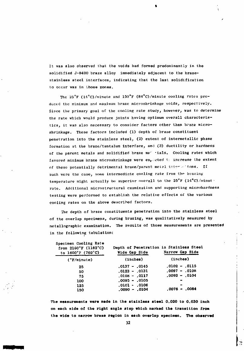
The depth of braze constituents penetration into the stainless steel
of the overlap speclmens_ during brazing_ was qualitatively measured by
metallographlc examination. The results of those measurements are presented
in the following tabulation:
Specimen Cooling Ratefrom 2160°F (I182°C) Depth of Penetration in Stainless Steel
to 1400°F (760°C) Wide Gap Side Narrow Gap Side
(°F/mlnute) (inches) (inches)
25 .0137 - .0145 .0102 - .011550 .0123 - .0131 .0097 - .0108
75 .0108 - .0117 .0092 - .0104
I00 .0095 - .0105 -'_ _ 125 .0101 - .0106 -
150 .0090 - .0104 .0076 - .0084
The measurements were made in the stainless steel 0.020 to 0.030 inch
on each side of the right angle step which marked the transition from
the wide to narrow braze region in each overlap specimen. The observed
32
1971006113-042
s
penetration into the stainless steel was intergranular in nature. The
extent of penetration was measurable because of preferential attack
of those intergranular areas by the acids used in metallographic etching
of the polished cross sections. As the above data show, greater
penetration was associated with slower cooling from the 2160°F (I182°C)
braze temperature, although overall variations were slight; l.e.,
penetration at the wide gap side for the 25°F (14°C)/minute and 150°F
(84°C)/minute rates were _0.014 inch and _0.010 inch, respectively.
The intermetalllc phase_ formed at the tantalum/braze interface during
brazing, varied in thickness from 0.0015 inch to 0.0005 inch for the
25°F (14°C)/minute and 150°F (84°C)/minute cooling rates 3 respectively.
Figures 14 and 15 depict representative mlcrostructures of the stainless
steel-braze-tantalum interfaces of the overlap specimens cooled at 25°F
(]4°C)/minute and 150°F (84°C)/mlnute rates_ and show the extent of the
indicated braze-base metals reactions. These data indicated that more
rapid cooling rates wou_ be advantageous for minimizing the possibly
detrimental braze/base metal reactions. The benefits derlved_ however_
dld not appear to proportionately offset accompanying increases in
microshrlnkage formation encountered with the more rapid cooling.
To provide a quantitative measure of the effects of cooling rate
variations on the ductility of brazed tantalum/Type 316 stainless steel
assemblles 3 hardness traverses were made across the overlap specimens
_ooled at 25°F (14°C)/minute and 150°F (84°C)/minute. The tests were
performed on both the wide and narrow gap portions of those specimens.
The results of these hardness determinations ere presented graphically
in Figures 16 through 19. A sketch of a full section view of a typical
overlap sample is shown on each _raph. The dashed line through the sketch
in each figure shows the location of the hardness traverse line for •
each specimen. The data indicated slight hardness increases in the
stainless steel-braze penetration zoneM, as compared with the values
.. obtained in the stainless steel remote (0.05 inch) from the braze ares
"' "i (Kn 190 vs Kn 160).*• . The somewhat smaller hardness gradients in the
, stainless steel of the slow cooled specimen reflects the occurrence of
,Kn = Knoop Hardness Number
33
1971006113-043
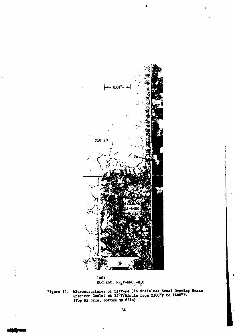
lOOx
Etchant: NII4F-I_O3-H20
Figure 14. K£crostructures of Ta/Type 316 Stainless Steel Overlap BraseSpec_en Cooled at 25°F/Kinute from 2160°F to 1400°F.(Top NB 821A, Bottom lqB 821B)
34
1971006113-044
o.
¢
", I ° .
• " , "_Z, ""'__ __dl_ _' "
'" IOOX
' E_chant : NK;F-HN03-1t20F_l;ure 15. Htcrostructure of Ta/T_pe _16 Stainless Steel Overl_tp Braze
SpecLmen Cooled st 150°F/Etnute from 2160°F to 1_00°_.(Top NB 820A, Bottom 1_ 820B)
3S
MII m
1971006113-045
l,
pucrl _tl47,RD og - ueup.z_qldomz)l36
I
1971006113-046
ml
0
37
1971006113-047

lb
1971006113-048
t)
t _ ,--I
.-1 ._,_ ,,.,4 {a.ij=
'" L%I ._l
_._2 _---. ._ _ ._
o..... N i
w |
1 ° i
k,
_ , , , ] ' o HE! _oI.i
=: "_E -:; el
4=1
!_ _ 0 _Q
_) 4) .,-I
I-, .el 0II _ _I,,_ ,_ _ ,
i
_'- "_ _ _
._. _
0 -
I ° I
_o'I :_n_ I_ Og - si_up_l doou_
39
1971006113-049
\
I
some homogenization caused by the longer high temperatu) exposure of
that specimen. The results also show that the formation of the inter-
metallic phase at the braze/tantalum interfaces effectively minimized
further diffusion between the braze and tantalum once _he phase had
been formed; thus, the sudden hardness decrease in the tantalum only
0.001 inch from the interfaces. The hardness variations found in the
tantalum were attributed to variations in the prior cold work at the
surface and center of the tantalum sheet material. Similar hardness
values were obtained in the tantalum near the tantalum-braze inter-
face and on the outside tantalum surfaces remote from the brazed areas.
Higher hardnesses were detected in the J-8400 braze alloy of the slow
cooled overlap specimen, as compared with the data for the rapidly cooled
sample. This behavior was unexpected, since the longer time, associated
with slower cooling, tended to allow ,..ore lnterdiffusion to occur: _hus
lower hardnesses were anticipated in the braze of the slower cooled
specimen. A possible cause for the observed results may have been related
to (1) the light load (50 grams) used in hardness testing, (2) the inherent
high hardness of the solidified braze (Kn 500-960), and (3) chemistry
variation in the braze. The hardness impressions were very small and
could have been significantly affected by the specific locations at which|
the readings were taken. Additional hardness testing was conducted in
the brazed areas of the two overlap specimensj using greater loads
(200 grams)anO numbers of impressions_ to provide more representative
sampling and clarify the situation. The narcow gap side of the braze of
the specimen cooled at 25°F (14°C)/minute had a hardness lower than that
of the specimen cooled at 150°F (84°C)/minute. For the wide gap side
o£ the braze t the situation was reversed. A greater number of
small microvoids (_0.0001 inch) were present in the wide gap area of
the specimen cooled at 150°F (84°C)/minute than in the same area of the
specimen cooled at 25°F (14°C)/mlnute and made reliable readings diffi-
_; cult. Thus, determining the effects of the cooling rates, by means of
hardness comparisons, was based on data for the narrow gap side of the
joints.
In summary I the metallographic examinations of penetratAon depths and
hardne_ testing data fop the overlap braze specimens indicated a sltsht
40
1971006113-050
f
advantage in using a more rapid cooling rate from the 2160°F (1182°C)
brazing temperature. However, the lesser braze mlcroshrinkage, obtained
by using a slower rate, was considered to be the most significant beneficial
factor because of tbe relatively low ductility of the J-8400 braze alloy.
Thus, a 25°F (14°C)/minute cooling rate, from the brazing temperature to
1400°F (760°C)_ was tentatively selected as the optimum rate. This
cooling rate_ and the 150°F (84°C)/minute rate were then used in the i
preparation of "proof" tensile specimens. _
Tensile Specimens Processing and Evaluation
Six tongue-in-groove tensile specimens were brazed using 25°F (14°C)/
minute (three specimens) and 150°F (84°C)/minute (three specimens) cooling
rates from the 2160°F (I182°C) braze temperature. Small pieces of tantalum
shim stock (0.02 inch and 0.002 i_.ch thicknesses) were positioned in the
tongue and groove areas of all six specimens, prior to brazing, to produce
brazing gaps equal to those present in tubular 2-inch OD, tongue-in-
groove, tantalum/Type 316 stainless steel brazed jotts. All six were
subsequently znspected by ultrasonic techniques. Those inspections
revealed that the faster cooling rate had produced more porosity, as
expected from earliez data for the overlap brazed specimens. Metallographic
verification of the microporosJty present in representative samples from
each group was postponed until completion of actual tension testing. The
:_ edges of the samples were ground in the joint areas to remove the slim
_ stock, which, if present, could have produced substantial effects on the
apparent strength of the assemblies.
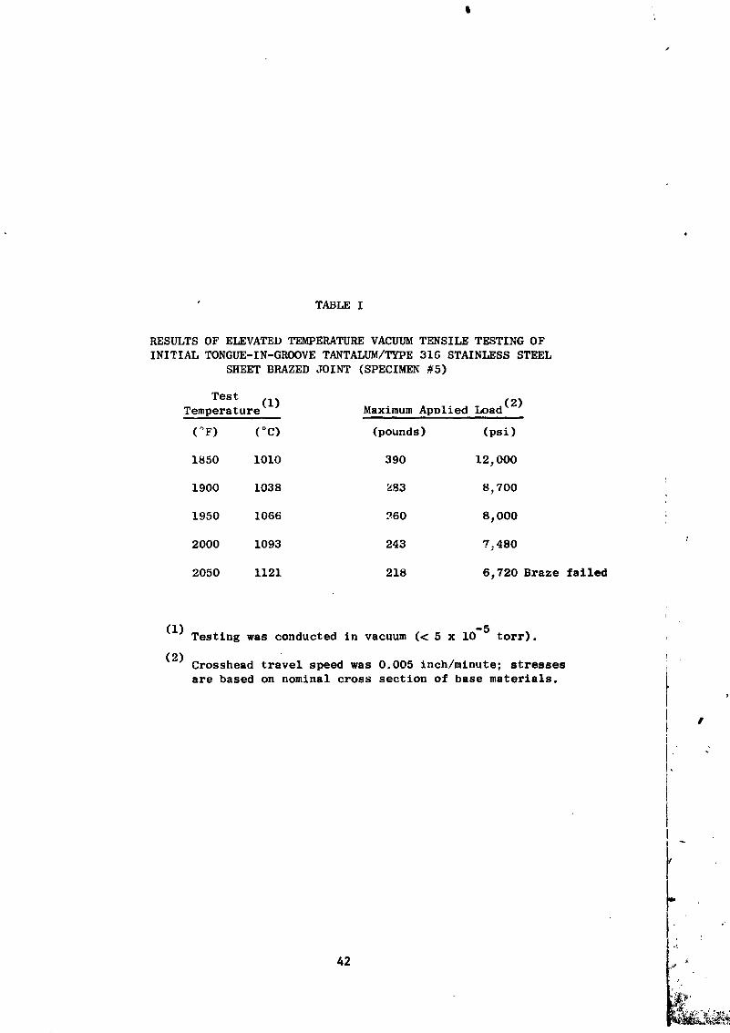
The initial tensile test specimen (cooling rate from 2160°F (1182°C) -
150°F (84°C)/minute) was loaded until failure in the J-8400 braze occurred;
a testing temperature of 2050°F (1121°C) was necessary to induce the
failure. The results of the znitial specimen (#b) tensile testing are
summarized in Table I. As indicated in the table, the specimen had been
.. _ stressed at 1850°F (IOIO°C), 1900°F (1038°C), 1950°F (1066°C), and
- 2000°F (1093°C) previously, until yielding of the parent metals was
observed. The testing, conducted in a vacuum environment, was visually
41t
_r_
1971006113-051
'l
s
" TABLE I
RESULTS OF ELEVATED TEMPERATURE VACUUM TENSILE TESTING OF
INITIAL TON6UE-IN-GROOVE TANTALUM/TYPE 316 STAINLESS STEEL
SHEET BRAZED JOIN"I' (SPECIMEN _5)
Test
Temperature (1) Maximum Apolied Load (2)
(°F) (°C) (pounds) (psi)
1850 I010 390 12,000
1900 1038 _83 8,700
1950 1066 ?60 8,000
2000 1093 243 7_480
2050 1121 218 6,720 Braze failed
(i)Testing was conducted in vacuum (< 5 x 10⁻⁵ torr).
(2)Crosshead travel speed was 0.005 Inch�minute; stressesare based on nominal cross section of base materials.
J
42 ! x
1971006113-052
\
monitored to determine the initial failure location and the propagation
path. The visual observation indicated that the eventual failure started
in the J-8400 braze at the top of the tongue and groove on the wide gap
side of the joint. The failure progressed from there, through the braze
and subsequently through the stainless steel at the root of the groove.
The solidus temperature on inltial heating, for the J-8400 braze alloy
in contact with Type 316 stainless steel, has been p_eviously observed
as 2000°F (1093°C). The tensile test temperature of 2050°F (1121°C) was
required tc cause braze failure because interactions of the braze with
the parent metals during the lower temperature tests had taken place,
thereby changing the characteristics of the braze material present. I
Because of this phenomenon, a test 1;emperature of 2000°F (I093°C), rather
than 2050°F (i121°C), was selected for the remaining tongue-in-groove i!
tensile specimens, j
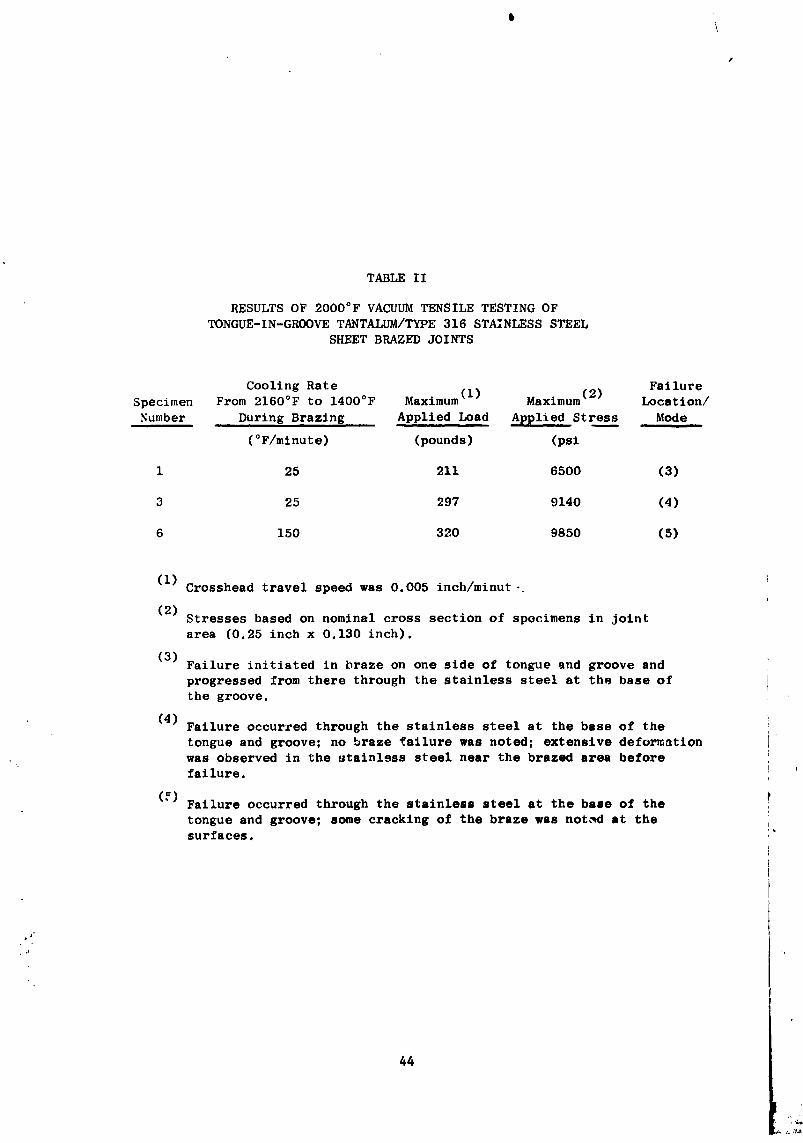
Three additional specimens were tested at 2000°F (I093°C) in vacuum.t
The specimens were loaded until failure was observed. The results of the
additional testing are presented in Table II. The results demonstrated
the good load carrying capabilities of tongue-in-groove brazements at
2000°F (I093°C). Since catastrophic failure of the braze occurred in
only one test specimen, significant comparisons of the strength data,
to assist in selection of a superior brazing cooling rate, was inappropriate.
Also, testing of the remaining two joints was abandoned because of the
inconclusive nature of the previously generated results.
• Ultrasonic inspection of tensile joints before and after testing was
performed to determine whether certain defects propagated and to determine
the extent of cracking from the edges after test. The primary procedure
used was C-scan recordings at more than one sensitivity. On some of the
joints an expanded scale C-scan presentation was used where the dimensions
on the recording were two or more times those on the actual _rt. Metal-
lographic examination of specimens #3 and #6 was made after tensile testing
to show both the nature of defects present which survived the tensile test
C and to show the extent of edge cracking, which the posttest ultrasonic
_ examination indicated, did not extend very far (_0.010 inch) into the
specimens. The metallographic examination confirmed th@ ultrasonic findings.
l:3
L
1971006113-053
\
TABLE I I
RESULTS OF 2000°F VACUUMTENSILE TESTING OFTONGUE-IN-GROOVE TANTALUM/TYPE 316 STAINLESS STEEL
SHEET BRAZED JOINTS
Cooling Rate • r • Failure
Specimen From 2160°F to 1400°F Maximum (lj Maximum t2j Location/
Number During Brazing Applied Load Applied Stress Mode
(°F/mlnute) (pounds) (psi
l 25 211 6500 (3)
3 25 297 9140 (4)
6 150 320 9850 (5)
(i)Crosshead travel speed was 0.005 inch/minut-
(2)Stresses based on nominal cross section of specimens in jointarea (0.25 inch x 0.130 inch).
(3)Failure initiated in braze on one side of tongue and groove and
progressed from there through the stainless steel at the base of
the groove.
(4) Failure occurred through the stainless steel at the base of the
tongue and groove; no braze failure was noted; extensive deformationwas observed in the stainless steel near the brazed area beforefailure.
(_)Failure occurred through the stainless steel at the base of thetongue and groove; some cracking of the braze was not,_d at thesurfaces.
44
1971006113-054
1
The major significance of these results was that the solidified J-8400
braze alloy had the ability to stop edge crach propagation at 2000°F.
The braze material in the remaining sections of the specimens was appar-
ently unaffected by the test exposures. The sol4dification characteristics
of the J-8400 braze alloy in the tongue-in-groove tensile specimens was
established bv means of the metallographic inspection of specimens #3
and #6. Those inspections revealed that lesser braze mlcroshrinkage
was present in the specimen cooled at 25°F (14"C)/minute than in the one !
cooled at 150°F (84_C)/minute, wblch confirmed that the desired conditions
for evaluation were present in the prepared samples.
Summarizing, the essential purpose of the tensile testing of the
tongue-in-groove sheet brazed samples was to determine w' 'er varying
quantities of defects (microshrinkage voids) in the J-8400 braze would
• proportionately reduce the shear load carrying capabiliti._s of tantalum'
Type 31_ stainless steel brazed assemblies. The primary conclusions
reached were (I) the solidified braze alloy could have major void areas,
equal to 25 percent of the total brazed area, and still withstand stresses
at 2000°F (I093°C) chat wo_Id cause failure of the stainless steel
components; (2) the braze material had the ability to stop propagation of
cracks present at its surfacez: (3) redesign of the test samples would be
required to yield assemblies completely susceptible to failure throu_
the solidified braze alloy; (4) employment of such redesigned braze
specimens would be necessary to provide meaningful data on the effects of
•. microshrinkage on the shear load carrying capabilities of brazed tantalum/
Type 316 stainless steel assemblies; and (5) a clear selection of an
optimum cooling rate based on the tensile test results alone was not
possible.
THERS_L SHIELDING STUDIES - TUBUIAR ASSFJdBLIES
The results of the cooling rate study, with sheet tantalum/Type 316
stainless steel brazed samples, indicated that the utilization of a slow
rate (25°F (14°C)/mlnute) during solidification of the J-8400braze alloy
yielded assemblies having optimum charscteristics_ i.e., minimum braze
"' microshrinkage and acceptable braze-base metal interactions. That basic
technique (braze at 2160°F (1182°C)/5 minutes, cool st 25°F (14°C)/minute
45
. i I
1971006113-055
r
1400°F) was employed in the fabrication of the initial tantalum/Type 316
stainless steel tubular production joints (S/N 1 through 10 and S/N 151.
e
Postbraze ultrasonic inspection of these assemblies revealed that
the concentration of braze microshrinkage varied from joint to joint.
The minimal extent of microshrinkage in some joints made them acceptable
as production joints_ while the degree of void formation in others
dictated their usage as either ultrasonic standards or correlation study
specimens. Additional processing refinements were decided to be r_quired
to reduce the quantity 3 or affect the position 3 of the braze microporosity.
Therefore_ two potentially beneficial variations in the brazing technique
for tubular assemblies were considered. The variations basically involved
adjustments of the thermal shielding used in order to (11 induce directtonal
solidification of the braze alloy during cooling of assemblies from the
brazing temperature_ and (21 produce a desired temperature distribution
radially across the tongue-in-groove area during brazing. Both of these
process refinements were investigated by the preparation of additional
tubularj tongue-in-groove assemblles 3 as indicated in following paragraphs.
Directional Braze Solidification
A potential refinement of the brazing process was explored as a
possible means of improving the quality of brazed tantalum/Type 316
stainless steel tubular transition joints. The basic technique variation
may be described as directional braze solidification. That condition in
tongue and groove braze joints could be attained by the initiation of
freezing of the J-8400 braze alloy at the base of the stainless steel
groove and then forcing the solidification to progress toward the top t
of the tongue and groove where the braze alloy had been prepleced.
Various methods for achieving that goal were entertained, including:
(11 moving the assembly being brazed out of the furnace hot zone at s
controlled rate and direction, (2) using a movable induction heating
coil to maintain desired transient temperature profiles during cooling.
(3) positioning of a heat retaining mass inside the tubular tantalum
joint components, and (4) positioning of heat shielding around the
tantalum Joint components to reduce radiant heat losses from that member
during cooling from the 2160°F (1182oc) brazing temperature. The latter
46
J.
1971006113-056
method was selected for evaluation because it was most readily adaptable
to the basic vacuum brazing furnace setup.
Some el the variables requiring evaluation for exploring the heat
. shielding method to achieve directional solidification were (I) the extent :
and configuration of heat shielding around the joint, (2) the position
of the joint in the vacuum furnace, (3) the effects of presence of braze
in the tongue and groove joint area, (4) the basic _uPnace heat shielding, j
and (5) the basic furnace cooling rat_. These variables were systematically i
investigated to determine their individual and cumulative effects. The i
general technique consisted of (I) heating a representative tantalum/ _-
JType 316 stainless steel, tongue-ln-groove, tubular joint, having the
conflguration shown in Figure 2, to the 2160°-2180°F (I182°-I193°C)
brazing temperaLure in vacuum; (2) measuring the steady state temperatures
on the outside surfaces of the assembly at several preselected positionsy_
in the joint area; and (3) determining the interrelated cooling rates at
those positions while reducing the nominal temperature of the assembly to
below the solidus temperature of the J-8400 braze alloy. The thermocouple
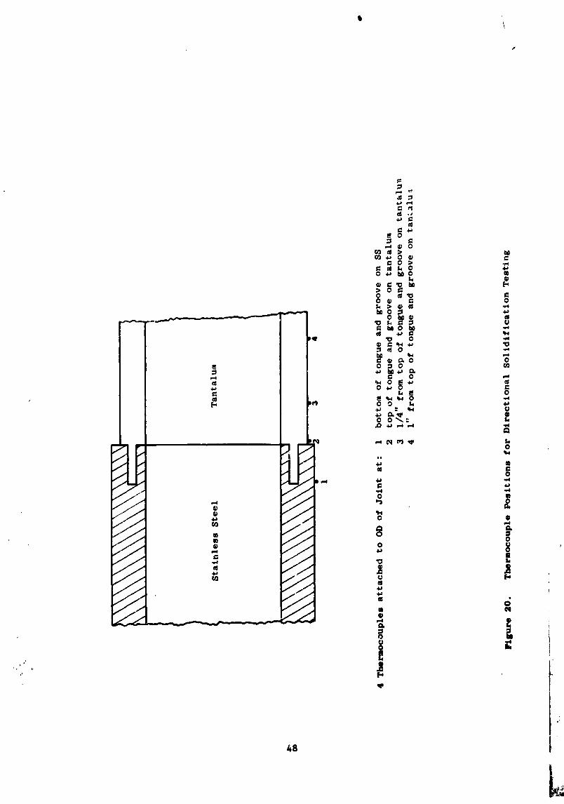
(Pt-Pt+10% Rh) measuring positions, schematically shown in Figure 20, were
as follows:
Position #i - On the stainless steel member at a point equal
. to the bottom of the groove.
Position #2 - On the tantalum member immediately above the top
of the tongue-in-groove area.
Position #3 - On the tantvlum member, 0.25 inch above the top
of the tongue-in-groove area' (slightly above lhe
braze preplacement zone in tubular assemblies).
Position #4 - On the tantalum member, 1 inch above the top of
the tongue-in-groove area./
Transient temperatures were measured with a fast response millivolt
recorder, shown in Figure 6. Initial testing was conducted with no braes
_. present in the Joint area. The purpose of those tests was to explore the
previously indicated para_oter_ to establish those radiation-heat reJecti_n
conditions which would teed to produce a greater cooling rate at position
#1 (bottom Of ,,e groove) than st position #2 (top of th@ groove), acsuming
47
1971006113-057
\
48 1
1971006113-058
uniform steady state temperature• at those location• prior to the cooling
cycle. Determination of the relation•hip o_ the transient temperature•
at position #3 and _4 versus those at position• #1 and #2 1Or a g_ven
test setup was ne._es•ary in these fi_t tests bscau•e a thermocouple
could not be attached at position #2 when the actual braze alloy was
preplaced at the joint.
Pl'eliminary test results (no braze present) established that the
tantalum compo.ent temperature measurements at position #3 were equiva?ent
to those measured at position #2, under both steady state and transient
conditions regardless of the presence or absence of thermal insulation.
Temperatures at position #4 varied from those •t the other t•ntalum
member temperature readout location•, dependent on the extent and location
of thermal shielding employed to achieve • desired test condition.
: Therefore, measurements at position #3 were used to define the steady
state temperatures and cooling rates of the tantalum component for all
subsequent thermal cycles used to a_er_ine those conditJon_ most conducive
toward achieving directional braze solidification in the tantalum/
stainless steel assemblies.
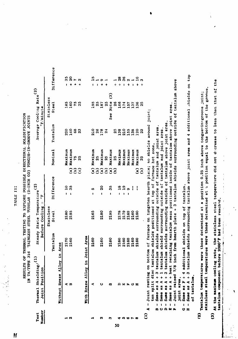
The results of the directional solidific•tion te•tlng are presented
in Table III. The initial te_t_, _erformed without braze alloy presentb
in the joint are•, indicattwi that a •lower cooling r•te of the tants]um
member_ relative to that of the stainless steel I could be attained by7
shielding the outside of the tantalum competent and the tongue-in-groove
area. The maximum difference in rates was 20°F (ll°C_/m!nute; Ta rate ffi
140°F (78°C)/minutej SS rate = 160°£ (89°C)/minute. The ahiel4ing used
; to produce those r©lattve rates consisted of three concentric, cylindrical
layers of tantalum; e•ch layer w•• •ep•rated by O.O_O-inch-dta_ter coiled
t•ntalum wire•. Although • reduction in the "'eJ•tive tantalum cooling rat_
could be achieved, the steady state temperature• across the Joint were
not equal. The stainless steel temperature, prior to cooling, exceeded
.! that of the ta.tal..- component by 35°F (20°C) (steady state temp_r:ture• -
" ' SS : 219F°F (1202°C), Ta : 2160°F (1182°C)). Reductions in the number of
shields present lessened the temperature dlflerence at • nominal 2160°F
(1182_C), but also resulted in greater _antalmx coolinl_ rates. These
initial results were very encouraging because having brass aZloy present
49t
1971006113-059
in the joint area was expected to equilibrate steady state temperatures
while the heat shielding present would maintain a reduced tantalum c_ling
rate relative to the stainless steel.
Continuation of the directional solidification testing was per-
formed with J-8400 braze alloy applied to the tongue-in-groove assembly.
|Thermocouples were attached appropriately and the assembly placed in
the vacuum furnace chamber in the desired location, after thermal
shielding had been positioned around the assembly. The assembly was
then heated to a nominal brazing temperature of 2160°F (I182°C) and the
temperatures of the stainless steel and tantalum components determined.
The cooling rates of both components were measured, as before, during
cooling of the assembly to the solidification temperature of the J-8400
braze alloy (approximately 2000°F (I093°C)). Different nominal rates
of cooling were employed to determine whether that varlahle had a signifi-
cant effect on the differences in the components temperatures at any
given time. All of the previously indicated factors, which influenced
_. the relative heat rejection tendencies of the assembly components, were
studied to establish those conditions which resulted in (1) a uniform
steady state temperature distribution across the tongue-in-groove joint
-.- area, and (2) a lowe_, tantalum cooling rate in relation to that of the 4
stainless steel. The data from the testing, with braze present in the
_" joint, indicated that the above requirements were met when the following
experimental conditions were employed:
• : 1. The assembly, stainless steel end down, was resting on the
bottom of the furnace atop a tungsten hearth plate.
., 2. Three cylindrical, concentric tantalum shields (tantalum shield
: material 0.003 inch thick) were positioned around the tantalum(
component. The shield package extended from the top of that
#._.' member to the top of the ton['ue-in-groove joint area.
•_ 3. Four disc tantalum shields were placed on top of the tantalum
_± component.
4. Ten split disc Ta shields were located at the top of the
furnace hot zone.
51
1971006113-069
\
1
No significant effects on directional braze solidification were
observed when the nominal rate of cooling from the brszing temperature
was varied from 25°F (14°C)/minute to a maximum value of approximately
140°F (78°C)/minute; i.e. 3 the measured lntercomponent temperature differ-
ential was constant for any given stainless steel component temperature,
regardless of the cooling rate employed, during cooling to 2000°F (1093°C)
which approximates the solidus temperature of the J-8400 braze alloy.
For example: when a maximum furnace cooling rate was used 3 the stainless
steel component cooling rate of 136°F (76°C)/minute exceeded that of the
tantalum member by 16°F (9°C)/minute. Thus_ after cooling for one minute_
the stainless steel temperature was measured as 2024°F (1107°C) and the
tantalum temperature was 2040°F (1115°C). The same stainless steel tempera-
ture and temperature differential were observed approximately 5.4 minutes
after the start of cooling at a nominal rate of 25°F (14°C)/minute3
indicating that either a slow or rapid rate produced the same transient
temperature differentials in the joint components, at least to the point
where freezing of the braze alloy occurred.
Two tubular, tantalum/Type 316 stainless steel joi_ts (S/N 12 and
S/N 14) were vacuum brazed under the cond_tions described above which
appeared most probable for achieving directional braze solidification in
those tongue-in-groove ass#mblies. S/N 12 was cooled at a basic furnace
rate of 150°F (84°C)/minute_ and _/N 14 at a rate of 25°F (14°C)/mlnutej
from the 2160°F (I182°C) brazing temperature to approximately 1400°F (760°C).
Both joints were ultrasonically inspected to determine the possible
beneficial effects of such thermal processing. Reiterating, the basic
premise for studying the directional solidification process variation
was that controlling the freezing pattern of the J-84OO braze alloy
could reduce the extent of mlcroshrlnkage void formation. The ultrasonic
inspection revealed that the assembly cooled at the fastest rate contained
the least microshrinkage. Since that higher nominal rate generated gremter
top to bottom transient temperature differentials in the Joint area, the
;, • nondestructive inspection data_ to some extent_ pointed out that the
directional solidification technique for brazing bimetallic Joints could
be potentially advantageous. However_ a comparison of 'the ultrasonic,O
resu|t_ (for both of the directlonally solidified Joints) with previoug
iRspection date for the initial tubular production Joints brazed at 216OAF
52
1971006113-070
• s
(i182°C) and slow cooled (25°F (14°C)/minute) with no shielding directly ._
in contact with the .joint components_ indicated that the previous method.c
produce_ bette_- assemblies in some instances. B_,_ed on that comparlson_
it appeared that the slow cool-homogenlzatlon approach was a better method
Jfor minimizing braze microshrinkage. It was f'illy reallzed_ howeve - that
more definitive testing would be required to completely evaluate the
directional solidification concept. Since the equipment and instrumenta-
tion requirements for further exploration of the directional concept
were quite complex# and further evaluation beyond the scope of the present
program 3 directional solldlfication studies were discontinued.
Radial Temperature Distribution Experiments
Fo!kowi::g the directional solidlfication studles 3 it was decided to
try an alternative approach to improve the braze quality. Some of the
initial tubular brazed jointsj particularly (S/N 5 and S/N 7) I exhibited
a greater degree of mlcroshrinkage_ primarily in the inner braze annuli_
than others. Several factors_ to be discussed further in later paragraphs_
may have contrJ.buted to this behavior. One of those factors was non-
uniform temperature distribution across the wall of the assemblies during
brazing# which could have effectively caused solidification of the braze
alloy to occur at some preferential locations# and pc_entially have iso-
lated a given braze area from the main supply fillet I while freezing was
in progress. Another way in which a nonuniform temperature distribution
could have contributed to more inner braze microshrinkage was that braze
solidification could have occurred from the outside toward the inside
of the joint. Reduction of this tendency by reversing the freezing p
direction (ID to OD) was desirable since the inner braze area is the more
important from a structural standpoint. It was decided this reversed solidi-
fication direction could be realized by reversing the apparent temperature
distribution; i.e.# outside Joint temperatures should be somewhat higher
than inside temperatures. Thus# exp_rimentation was undertaken to determine
the thermal shielding conditions which would produce higher relative
temperatures on the outside of the tubular assemblies and thereby induce I
braze solidification to take place from the inside toward the outside of
the Joints.
53
1971006113-071
Thermal Equilibrium Experiments
The general method employed to establish optimum radiant shielding
conditions for the brazing of a tantalum/Type 316 stainless steel 3 tongue-
in-groove assembly is contained in the following paragraph.
The thermal shielding used at the top of the furnace hot zone con-
sisted of either 13 4_ or i0 layers of tantalum discs_ each 0.005 inch
thick. Some of the discs for an individual shield package were diametrically
spllt_ while others contained only 0.5-inch-diameter holes for thermo-
couple penetration into the furnace hot zone. The thermal shielding in
the vicinity of the assembly being brazed_ consisted of (i) two concen-
tricj cylindrical tantalum shields_ each 6 inches longj covering the
entire length of the joint_ placed between the furnace heating elements
and the tubular jointsj and/or (2) four continuous tantalum disc shields
resting on top of the tantalum component of the assembly. The joint was
placed in the vacuum furnace and the heat shielding arranged around it.
The assembly was heated to the desired brazing temperature and steady
state tempcratures were measured at selected ID and OD joint locations.
The assembly was cooled at 25°F (14°C)/mlnute to 1400°F (760°C); there-
afterj it was cooled to room temperature at nominal furnace rate. _et
thermocouple measuring positions 3 schematically shown in Figure 21_ for
the test cycles are listed below_
- Position #I - On the stainless steel OD at a point equal to
the base of the groove.
Position #2 - On the stainless steel ID st a point equal to the
base of the groove.
Position #3 - On the tantalum OD above the braze area (0.5 inch
above the top of the groove).
Position #4 - On the tantalum ID above the braze area (0.5 inch
above the top of the groove)._'
.;_i A ten-layer split disc furnace top insulation package_ and no
" direct par_ shielding_ were employed for the brazing of Joints S/N 1
through S/N 10 and S/N 15, The steady state temperature measurements
54
1971006113-072
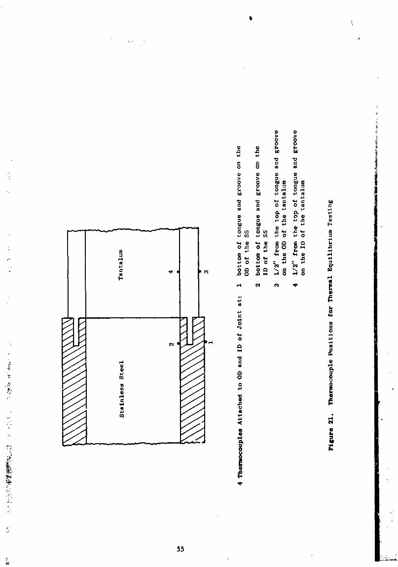
I, \
55
1971006113-073
at positions No. 1 and No. 2_ during brazing of those assemblies_
indicated slightly higher temperatures at the outside surfaces than at
the inside (iT = IO°F (5.5°C). These temperature conditions were expected
since the furnace heating element surrounded the assembly. However, on
cooling at a rate of 25°F (14°C)/minute from the brazing temperature_ in-
version of those conditions was observed shortly before the liquidus
temperature (_ 2050°F (ll21°C))of the J-8400 braze alloy had been reached;
i.e.3 the inside joint temperature, during braze solidification 3 exceeded
that at the outside. This phenomenon most probably resulted in the
undesired outside-to-inside freezing of the braze alloy.
The first attempt to correct the described condition involved the
placement of two cylindrical shields around an entire assembly to reduce
heat rejection from the outside surfaces. Results of this initial modifi-
cation generated the desired temperature gradient conditions_ but the
effect was too pronounced. Thusj the steady state temperature of the
tantalum component at position No. 4 was 72°F (40°C) less than that of
the stainless steel member at position No. 1. The second modification_
i.e., four continuous disc shields positioned on top of the tantalum_ in
_ddition to the previous two cylindrical shields around the Joint_ reduced
the gradient to 52°F (29°C). Thereafter: the furnace top shielding package
was changed from the split disc type to the continuous disc configuration.
Subsequent brazing trials, conducted with a four-contlnuous-disc furnace
top shield stackup_ indicated small OD-ID translcent and steady state
temperature gradients (_ 20°F (11°C))_ with the inside surface being cooler.
This was the desired thermal distribution condition, and the indicated
shielding parameters were selected for use in the preparation of subsequent
production joints.
In summary_ the ultrasonic inspecticn of several tubL,lar tantalum/
Type 316 stainless steel brazed assemblies revealed that the slow cool-
homogenization approach produced generally superior braze freezing charac-
teristics in the tongue-in-groove area than those exhibited in '*directionally
• ?. solidified" assemblies, Modifications of the thermal Insulation setup
were necessary_ however I to establish those conditions which would result
in the initial braze solidification at the inner brazo annulus of the
tubular Joints, After several trials_ a shield_ng technique was selected
for the brazing of subsequent production Joints,
56
1971006113-074
t
I)EV_:IDP_,IEN'I'OF ULTRASONIC METHOD I.DR INSPECTING TLWIULAR ASSEMBLIES
The primary purpose of this portion of the investigation was to
develop a reliable ultrasonic technique for the nondestructive inspection ,_
of the brazed tantalum/Type 316 stainless steel transition Joints. The annu- '_
Zar braze areas at the inside and outside of the tongue member represented _
the most important sections of the joints from a structurai standpoint,
and control of the braze quality therein was vital to realize cptJ;aum
joint characteristics. Thus, the function of the uitrasonlc inspection
was to accurately depict the braze characteristics in those areas, and
thereby establish the integrity and soundness of the fabricated braze-
ments. The two essentially separated braze sections or bands posed
a difficult inspection problem, even for ultrasonics with its inherent
capability for exploring the internal volume of a component or assembly.
:: The layers are relatively close to each other and to the tubing surfaces
/ (refer to Figure 2), and the ability to ultrasonically resolve each portion
of the five layer sandwich (stainless steel-braze-tantalum-braze-stainless
steel) was, therefore, difficult. The situation was compounded because
increased power levels were required to permit inspection of the inner
braze snnuli at the same detection sensitivity as that related to the
outer braze areas. Greater power inputs were necessary because the
, sonic beam had to pass through the somewhat inhomogeneous outer braze
material to reach the inner zone. The described difficulties in the
ultrasonic inspection of the transition Joints were eliminated
by the use of suitable inspection standards so that relative inspection
sensitivities at the two braze layers could be evaluated and adjusted.
-_, Preparation of such standards required the machining of well defined.
. artificial defects into the brazed areas of a representative tubular
-_ tongue in groove assembly. These artificial defects were of varlous
sizes so that different levels of inspection sensitivity could be
realized in subsequent examinations. Other assemblies were brazed,
, _ ultrasonically inspected_ and subsequently exm=tned metallographtcally,
,, to verify the capability of the developed ultrasonic method for
_ indicating the condition of a particular brazed joint. The preparation
_ and evaluation of standsrds_ metallogrlphtc-ultruon_c date correlation
to verify inspection capabilities, and the ultrasonic techniques employed
are discussed in following paragraphs.
57
1971006113-075
I
Ultrasonic Standards Preparation and Evaluation
The equipment and general ultrasonic technio'Je employed for tubular
joint inspection was the same as that used in inspection of sheet
brazed assemblies, with some minor modifications. Both "C-scan" and
"modified A-scan (X-Y)" recordings were obtained for all tube joints in
this phase of the investigation. The first tubular assembly brazed
was intcnded for use as an ultrasonic calibration standard. The joint
was vacuum brazed at 2160°F (i182°C)/5 minutes and cooled at 25°F (14°C)/
minute from the brazing temperature to 1400°F (760°C). Thereafter, it
was ultrasonically inspected to insure that the areas selected for sub-
sequent hole placement were essentially defect free, and any porosity
present in the solidified braze would be negligible in comparison with the
holes to be machined. The joint was cut so that the calibr_tlon holes could
be machined directly into each of the braze zones from the ID of the joint,
as shown in Figure 22. During the machining process the wide-gap outside
braze cracked around most of the circumference. This ultrasonically
obscured all the holes in the inner braze annulus and most of those in
the outer braze zone. Thus, it became necessary to use a second tubular
joint for the calibration standard. The machining technique for this
assembly was altered to eliminate the braze cracking problem; i.e.. _:
the .joint was not sectioned through the brazed area to slmpllfy tlleF
hole machining operation. The radial, flat-bottomed, holes in the tube
joint were produced by electrical discharge machining (EI_) with a special
electrode designed to reach the desired interior positions. The
smallest hole that could be prepared by that processing technique had #
a diameter of 0.007 inch. The radial holes machined into both braze
areas were, therefore, 0.050, 0.020, 0.010 and 0.007 inch diameter. " "
The dvsired axial hole in the outer braze annulus could not be produced,
since the joint area was not exposed by transverse sectioning.
Experiments with tantalum and stainless steel sheet materiels were
conducted to determine the best method for preventing braze flow in
selected areas, for subsequent fabrication of an intentionally misbrszed, t
tongue-in-groove, tubular assembly. Those experiments indicated that
mechani_al removal by filing and subsequent careful painting of
braze "stop-off" materials on specific areas could be successfully used. !
58
i 97 i 006 i i 3-076
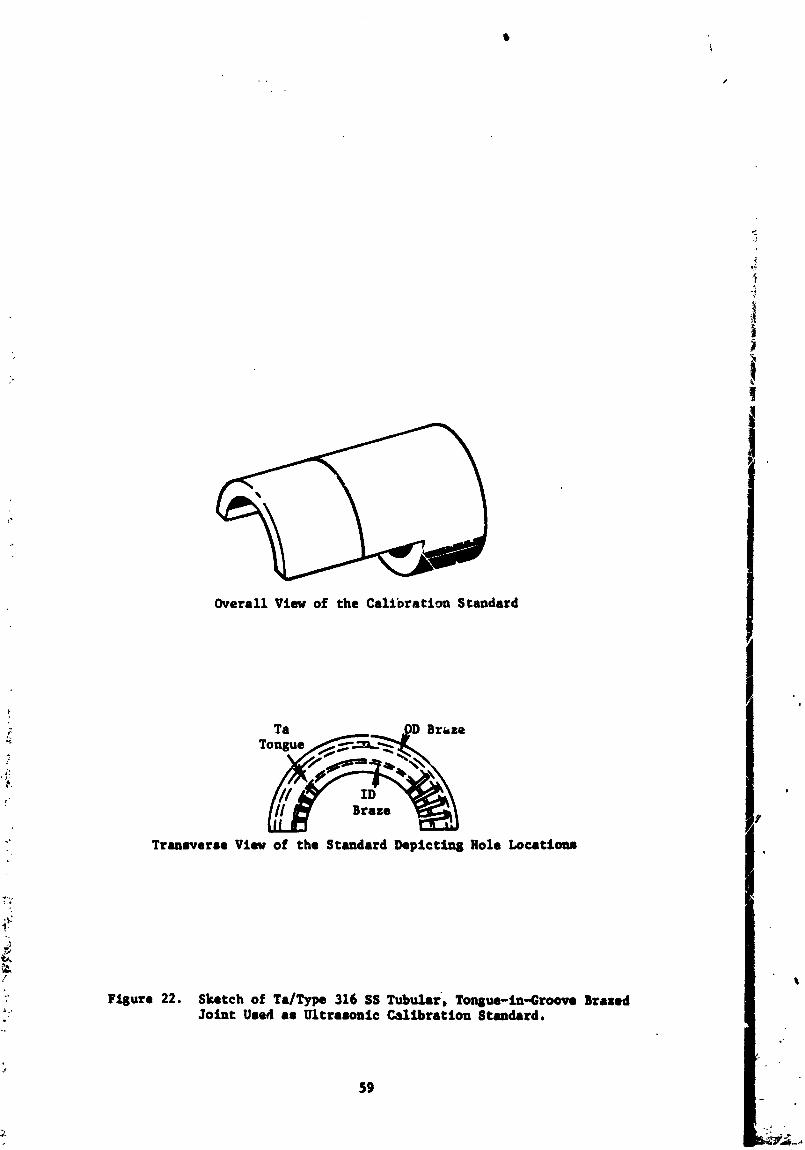
Overall View of the Cal£brntion Standard
_. Ta .ODBraze
Tongue _-_._"'_--_,,,._
Trsnsverse View of the Standsrd Depictin8 Hole Locat4ons4,
f
_'" Yisurs 22. Sketch of Ta/Type 316 SS TubuZar, Tonzus-in-Groove BrazedJoint Used as Ultrasonic Cslibration Standard.
59
2
1971006113-077

t
s
Thereafter, the o, tstde diameter of the tongue of a tantalum joint
component was _tled to remove 0.005 lnch of material over two separated
90 ° portions o_ the tongue circumference. Those two areas and alternate
90 ° sectors on the ID were then painted with "stop-,)ff". The i_in_
components were then assembled and braze alloy preplaced at ;_,_,.. the
Joint OD aud ID in the area_ where no "stop-off" was present. The
assembly was t_en vacuum brazed at 2160°F (1182°C) for 5 mtnutes_ and
cooled _t 25°F (14°C)/mtnu_e to 1400°F (760°C). Via,m1 examination
of the joint after brazing indicated that the desired braze flow
characteristics were obtained, as schematically shown In Figure 23.
Ultrasonic inspection of that joint, before metallographlc examtnatton_
also indicated chat the desired result_ had been achieved; l.e._ adjaeent
90 _ sections on the inside and outside of the tongue and groove were
_lt,_er completely filled with braze or contained nc_e st all. The
Intentionally mlsbrazed tubular joint was exa_Jlned metallographtcally
at two transverse planes through the tongue and groove joint ares.
Those examinations verified that the ultrasonically predicted braze-
no braze conditions in the assembly had been achieved. The excellent
agreement between the destructive and nondestructive data pointed out
the capability of the ultrasonic technique for determining completely
nonbonded areas in the brazed Joints.
Ultrasonic Inspection Sensitivities
Re.lected signals from the ultrasonic scanning of the flat-bottomedt
holes In the ultrasonic standard tube ass_sbly were compared with those
obtained from the natural defect present In one of the overlap brazed I
Joints. It was determined that ultrasonic sensitivities used in the
sheet sample inspection would also be adequate for inspection o_ tubular
brazed Joints. Thus, it was no longer necessary to use the n_tursl cali-
bration defect in the overlap specimen to assist in _urther u_rasonlc
inspection of tube Joints.
Ultrasonic "C-scan" recordings at various sensitivities were made ,_t
on several of the tntt;=11y prepared tubular asseabltea to selmct the
lost meaningful sensitivity setttng_ and techniques foe" following tunular
assemblies inspection. However 2 only one sensitivity aetttn8 _s .
y_
60
1971006113-078
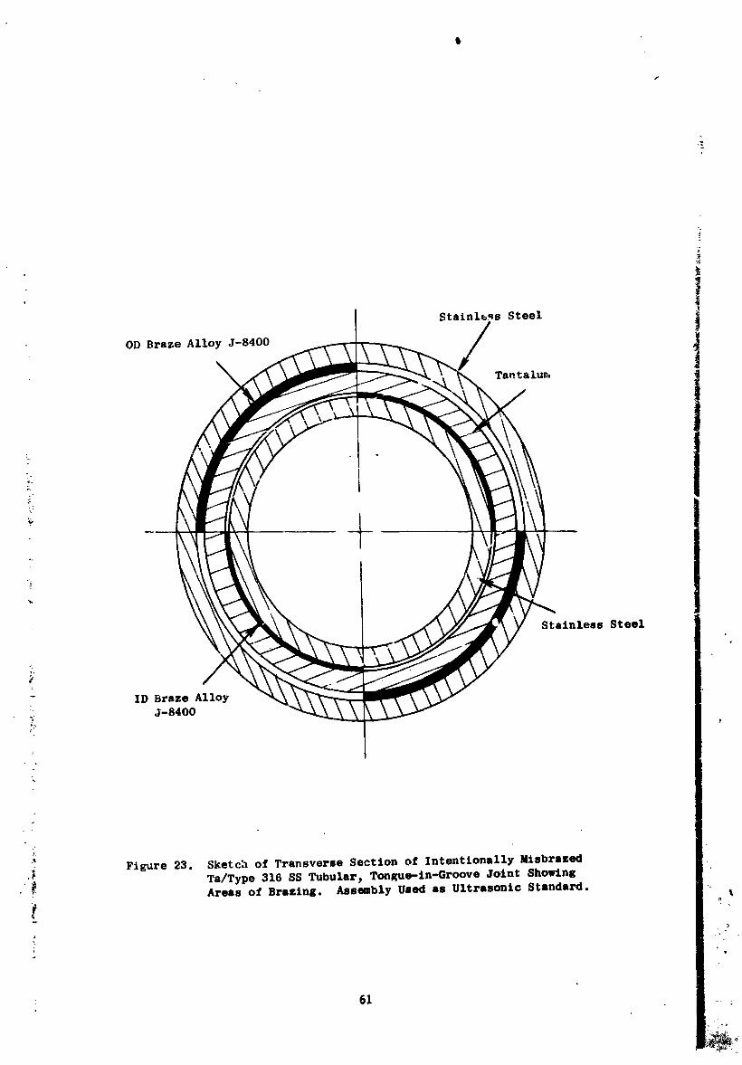
1Stainl_s Steel _
OD Braze Alloy J-8400
Tsntalu_
Stainless Steel
ID Braze Alloy
_. J-8400
._ Figure 23. Sketch of Transverse Section of Intentionally Mlsbrased._ Ta/Type 316 SS Tubular_ Tongue-in-Groove Joint Showing
• Areas of Brazing. Assembly Used as Ultrasonic Standard.
f o_
: 61
1971006113-079
\
f
utilized in generating the X-Y recordings. This sensitivity was adjusted
such that a 0.010-inch diameter calibration hole in the braze annuli was
represented on the X-Y recording as a 10 unit amplitude signal and a 50
percent of full scale amplitude on the ultrasonic display unit, Figure
24 represents a typical "modified A-scan" recording obtained from the
inspection of a tubular tantalum/Type 316 stainless steel brRzed joint.
Specific planes in some tubular joints were selected for the metallo-
graphic correlation efforts because the X-Y recordings of those planes
demonstrated a variety of signal amplitudes. The selected planes also
contained well defined transitions from one ultrasonically indicated
condition to another_ which permitted the determination of the corre-
lation between signal position and actual physical location on the
assembly being examined.
CORRELATION STUDIES
The purpose of the correlation _udy was t_ determine by metallo-
graphic examination of tubular joints_ the nature of defects producing
various ultrasonic indication amplitudes and configurations and_ based on
these results_ to establish a criteria for acceptance or rejection of the
joints by ultrasonic inspection only. Ultrasonic inspection of a com-
ponent or assembly depends on the penetration and propagation of a Iow-
magnltudej mechanlcal energy sonic beam through the materlal being examined.
Structural variations or defects within a materlal that significantly
influence stress distribution under an applied mechanical load_ would have
a corresponding effect on the transmission and distribution of a sonic
wave passing through the area of significance. Defects with sharp corners
or large length-to-thlckness ratios represent hlgh-stress concentration
areas which tend to reduce the strength of a material to a greater extent
than a similar size defect having a spherlcal configuration. Transmission
of an ultrasonic beam through a zone containing defects is similarly
;. affected more by the degree of stress concentration than by the physical
size of the flaws_ providin_ the size of the latter does not approach
objectionable limits. Thus_ metallurgical interactions I 0rastic chemistry
variations and round voids tend to produce relatively slight disturbances
in the ultrasonic beam transmission in comparison to thoae induced by
62
1971006113-080
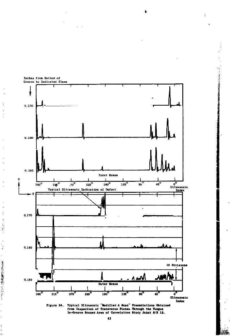
Inches from Bottom of -_Groove to Indicated Plane
1 '• 0.170 "'J.- .............
0. 150
Y
_. 3600 3]_ ° .70 ° 225 ° 180° 135 ° 9_ n 45° 0°
UltrasonicTypical Ultrasonic Indication oi Defect Index
x I I I i
1971006113-081
cracks_ platelike voids 3 and other high-stress concentrating defects.
These factors were considered in the inspection of the tubular joints.
_ne ultrasonic velocity change in tantalum was beneficial in the
preparation of well-defined_ "C-scan" (plan view) recordings of the joint
areas because the back surface (ID surface of tube joint) indication
shifted to a later time where tantalum was encountered. That is_ the
propagation velocity of tae ultrasoni_ beam in tantalum is much less than
in the stainless or braze alloy and_ thereforej appears as an apparent
"increase in thickness." Thus 3 the "C-scan" recordings showed a sharp
demarcation line (white to black) when the bottom of the groove was
reached. This shift was also used in determining the physical location
of the "modified A-scan" recordings and especially in determining the
reference position for comparison of ultrasonic recordings with metallo-
graphic sections. Also 3 the degree of uncertainty in the location of
the source of an ultrasonic indication was reduced through minimizing
possible refraction by inspecting _he tubular joints in the radial direction
only.
Two joints (S/N 6 and 7), intended for the correlation investigation 1
were vacuum brazed at 2160°F (1182°C)/5 minutes_ using initially selected
shielding conditionsj and subsequently cooled_ during braze solidification_
at a rate of 25°F (14°C)/minute. These assemblies were ultrasonically
inspected and areas within the joint selected for microstructural examina-
tion. Thereafter_ they were cut perpendicular to the assembly axis,
adjacent to the tongue-in-groove area_ in preparation for metallography.
The assemblies were then rough machined by surface grinding to arproach
the desired transverse planes to be examined. The direction of approach
into the joint area was from the stainless steel end of the assembly.
The first of these correlation study joints was examined metallographically
near the preselected transverse inspection plane. The examination revealed
cracks present in the solidtf_ed bra_e alloy in a 90 ° section of the
inner annulus between the tantalum tongue and stalnless steel groove.
_ The observed cracking was believed to have resulted from the preparatory
surface grinding operat$on, since the earlier ultrasonic inspection had
not indicated the presence of any such gross defect. The Joint had been
prepared for metallograpbic examznation by removing material from the
64
1971006113-082
i
I
stainless steel end el the assembly to accurately determine the g-oovez
base location which was the measured reference point for ultrasonic
inspection. It was postulated that when the actual joint area was ,_
reached_ the support of the braze material_ provided by the interconnected __s_ainless steel material below the groovej was removed leading to the
observed br_e f_ilure. The metallographic processing of both correla- _
tion study specimens was interrupted in order to reinspect the joint iJ
areas by ultrasonics to verify that the observed cracking had been induced
by the preparatory machining operation. The ultrasonic reinspection
demonstrated th_ ' the failures had indeed been caused by the metallographic
processing; and replace,aent joints were_ therefore, selected to complete
the study.
Ultrasonic inspection of the "directional solidification" tubular
study joints (joints S/N 12 and 14) indicated that their quality was
below acceptable production joint standards. However, the ultrasonic
X-Y recordings for those joints displayed several interesting features s
and they were_ the-efore_ chosen as the replacement joints. A third
assembly (joint S/N 5) was also selected for the correlation investi-
gatlon. Joints S/N 5 and S/N 12 were selected for transverse planes
examination and joint S/N 14 for longitudinal planes study. Specific
planes in each joint were selected for metallographic examination, based
on the dltrasonlc inspection data pertaining to those assemblies.
Resolutlon of the braze cracking problem, during metallographlc
preparation of joints S/N 5 and 12 for transverse sections_ was accom-
plished by observing two additional precautionary measures during the initial
material removal stages. The first was to leave the interconnected
stainless steel material intact by approaching the brazed area frcm
the tantalum end of the Joint. This new technique required more lapping
than the previous procedure, because the initial transverse cut_ through
the tantalum member, had to be. made above the external braze fillet area. The
second precautionary measure observed was the bulk material removal by
circular lapping only. A combination process of back-and-forth grinding _
coupled with lapping had been utilized previously. The circular lapping
substantially reduced the extent of stresses induced in a direction
perpendicular to the minimum supported braze area. The transverse planes
55
1971006113-083
I
I
examination, after completion of the metallographic processing, revealed
that the problem had been resolved.
Preparation of joint S/N 14, for the microstructural examination of
longitudinal planes_ presented a somewhat different_ but related_ problem;
i.e._ residual stresses presen_ in the tongue and groove area after brazing.
Stress imbalance can produce catastrophic failures of the solidified J-8400
braze alloy during longitudinal sectioning unless precautionary measures
are observed. To overcome this difficulty_ the entire assembly was en-
cased in thermal setting plastic before axial sectioning to inspect a
particular angular position. The mounting material thus provided the
required support in the braze area and prevented failure during sectioning.
The correlation study joints were processed to determine the micro-
structures present at the following locations in the brazed areas:
Joint S/N 5 - At two transverse planes through the joint area_
0.180 inch and 0.120 inch (axial distances) from
the bottom of the groove in the stainless steel
component.
Joint S/N 12- At two transverse planes through the joint area,
0.160 inch and 0.110 inch (axial distances) from
the bottom of the groove in the stainless steel
component.
Joint S/N 14- At two longitudinal planes, 104 ° and 180 ° counter-
clockwise_ rotational distance from an arbitrary
ultrasonic reference point. I
The microstructures at each plane were compared on a point-by-point basis I
with the "modified A-scan" presentations for those planes to establish the
degree of correlation_ and thereby determine the capability of the ultra-
sonic technique for representing the quality of the joints.r
_ Photographs (45X) along the tongue-in-groove brazed areas were
: obtained fo_ each p3_ne of ex_mination in the ,=orrelation samples.
These photomicrographs were then compared directly with the rempoctive
"modified A-scan" (X-Y) recordings for the different planes. Figure 24
presents a typical A-scan recording for several p_anea in Joint S/N 12;
66
1971006113-084
\
#
Figures 25, 26 and 27 depict the unetched photomicrographs obtained at
different angular positions around the transverse planes of examination
in those assemblies. The comparisons revealed the generally good cor-
relation between the ultrasonic data and the actual microstructures
present. The majority of ultrasonic indications of defects were produced
by the presence of microshrinkage voids in the solidified J-8400 braze
alloy. Wherever the ultrasonic recordings showed no vertical signal
displacement, no significant defects were observed. Conversely, recording
deflections of a significant magnitude were directly related to the size
of the defects; i.e., the greater the recording signal height, the larger
the effective size of the corresponding defect. The defects found tended
to be smaller in circumferential dimension than was predicted by compari-
son of the respectiv£ defect signal with the calibration standard; i.e.,
a defect, which produced _n Indication equivalent to that obtained from
a 0.010-inch-diameter calibration hole_ tended actually to be less than
0.010 inch in circumferential dimension.
The metallographic examination of the transverse planes in joints
S/N 5 and S/N 12 revealed that the tongue and groove diameters were not
concentric and the braze thicknesses correspondingly varied from the
anticipated values. The inner braze thicknesses thus ranged from _ 0.0005
inch to 0.008 inch; the outer braze annular dimensions were also observed
to correspondingly vary. This behavior tended to change the nature
of any defects present in the braze areas_ primarily in the inner braze
annuli. At the closest diametric point of approach, the restricted
volume caused voids present to have very thin platellke configurations,
and they, therefore, represented stress concentrations equivalent to
that of a natural crack. This type of effect was observed in joint
S/N 5; a large, almost continuous, indication of defect was found on
a number of the "A-scan" planar presentations of the inner braze area
of that assembly. The area in question had an axial length of about
0.1 inch and covered approximately 180 ° of the joint circumference.
• " Extensive microstructural examination (IO00X) revealed that a large
portion of the signal was produced by the preaence of microscopic voids
at the tantalum-braze interface. Further# one small ar_s_ approximately
10 degrees in circumferential length, actually exhibit_d the presence of
67
1971006113-085
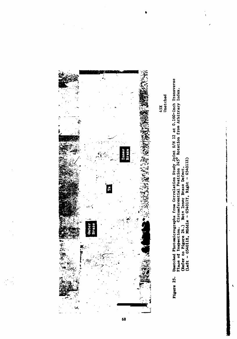
i
1971006113-0_
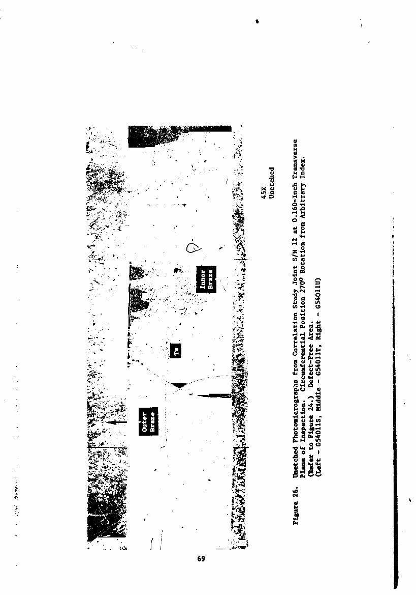
1971006113-087
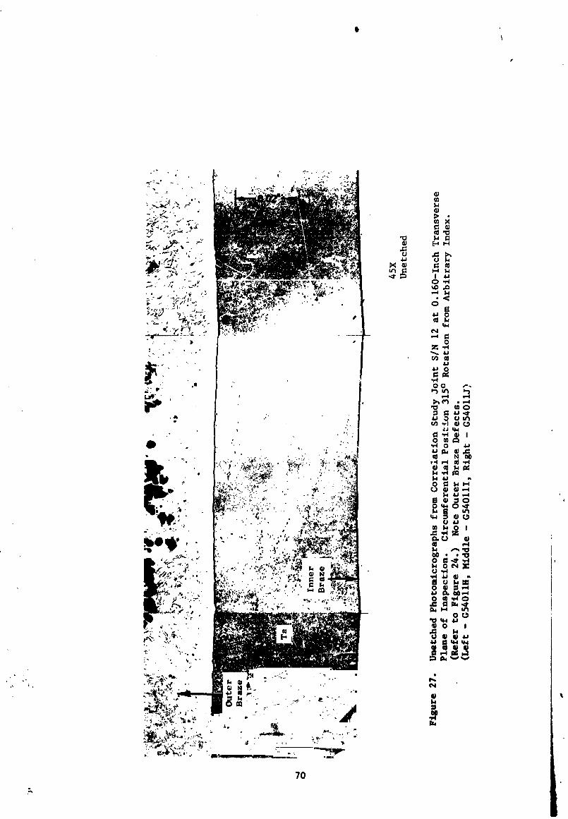
I
1971006113-088
mlcrocracks at that interfacial location. The shape and extent of the
ultrasonic signals generated at that location were materially different
from any _ther indications of defect encountered; thus_ the future
identification of any rejectable assembly would be relatively straight-
forward. The microstrtzctural examination of the other transverse plane
correlation sample (joint S/N 12) also reveal_d the presence of some
mlcrocracks Ill the thin brazed area. Since the processing, used inI
o._ these brazed assemblies, had been shown tmetallographic preparation
to be capable of causing cracking of the braze material, two other I
transverse planes in joint S/N 5 were very carefully prepared for
additional mlcroscoplc examination. Those examinations revealed that
the metallographic process was still somewhat in question and would
require refinement to eliminate the cracking difficulty.
The mtcrostructures present at the longitudinal planes of exami-
. nation in joint S/N 14 could not be compared completely wlth the X-Y
ultrasonic recordings because those scans had been obtained by essentially
transverse sweeping of the joint at separated (0.010 inch) planes. Thus,
comparisons could only be msde at the points of intersection between the
two longitudinal planes and the multiple ultrasonic transverse planes. The
microstruczural study again prov.ded evidence of the eccentric relation-
ship of the tongue and groove. The study further demonstrated the
capability of ultrasonic inspection for the identification of the brazed
characteristics of tongue-and-groove tubular assemblies. In fact# almost
100 percent agreement between the ultrasonic data end the physical structures
present was realized The defects encountered were ell braze microshrinksge
cavities.
The correlation Joints were also examined in the etched condition
to determine the extent of the metallurgical interactions between the
J-8400 braze alloy and the tantalum and stainless steel parent metals,
at various positions in the tongue and groove area. Typical micro-
structures obtained are presented in Figure 28 Mtcrohardness surveys
.+ _ (Knoop - 25 gms load) wlre also made across each plane of mmmlnatlon
to assist in the dete_Inatlon. Figures 29 and 30 depict typical
hardness graphs obtained from these measurements on transverse planes
in Joints S/N 5 and S/N 12. Sane observations from the mmmtnstton
end hardness testing of Joints S/N 5_ 12 and 14 follow:
71
1971006113-089
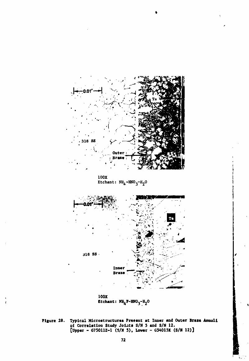
FL_ure 28, TypLcal M£crosCructures Preeent at Inner and Outer Brase Anuul£of Correlation Study Joi_Cs SIN $ and SIN 12.[Upper - G75011Z-I (S/N 5), Lower - G_OI$K (S/N 12)]
72
1971006113-090
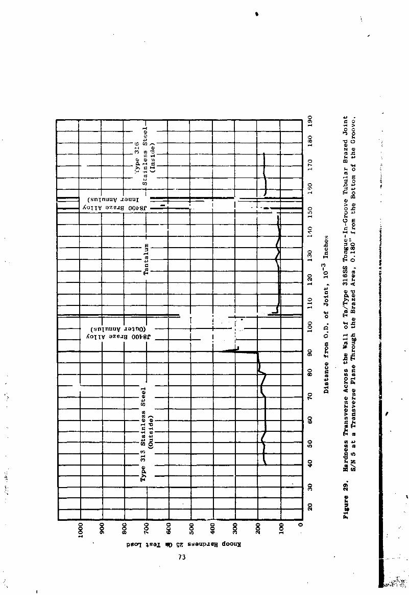
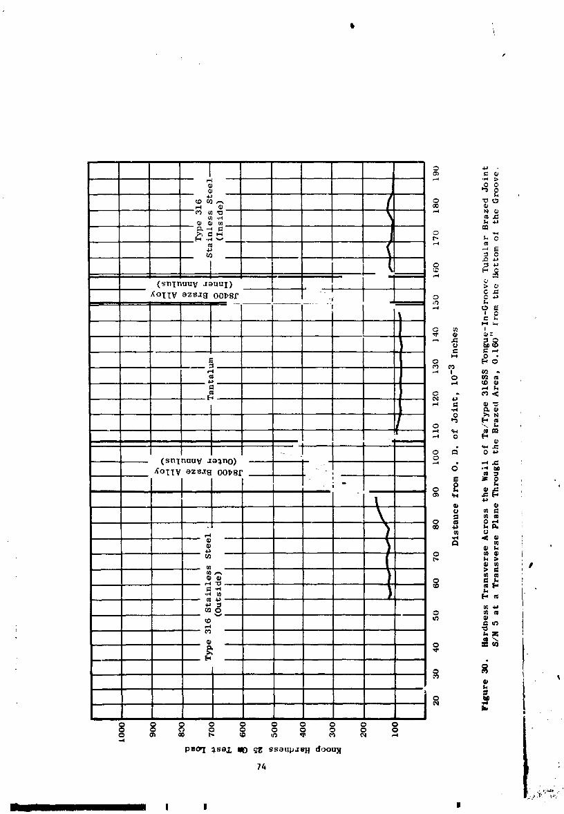
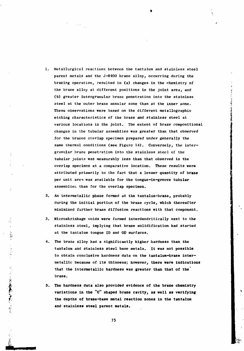
1. Metallurgical reactions between the tantalum and stainless steel
parent metals and the J-8400 braze alloy t occurring during the
brazing operatlonj resulted in (a) changes In the chemistry of
the braze alloy at different positions in the joint area_ and
(b) greater Intergranular braze penetration Into the stainless
steel at the outer braze annular zone than at the inner zone.5
These observations were based on the different metallographic
etching characteristics of the braze and stainless steel at
various locations in the joint. The extent of braze compositional
ichanges in the tubular assemblies was greater than that observed
for the brazed overlap specimen prepared under generally the
same thermal conditions (see Figurc 14). Conversely_ the inter-
granular braze penetration into the stainless steel of the
tubular joints was measurably less than that observed In the
overlap specimen at a comparative location. These results were
attributed primarily to the fact that a lesser quantity of braze
per unit areq was available for the tongue-ln=groove tubular
assemblies than for the overlap specimen,
2. An intermetalllc phase formed at the tantalum-brazej probably
during the initial portion of the braze cyclej which thereafter
minimized further braze diffusion reactions with that component,
: 3. Microshrlnkage voids were formed interdendrltically next to the,o,
stainless steelj implying that braze solidification had started
? at the tantalum tongue ID and OD surfaces._:
4. The braze alloy had a significantly higher hardness than the
, tantalum and stainless steel base metals. It was not possible
": to obtain conclusive hardness data on the tantalum-braze inter-
metallic because of its thinness; however I there were indications
:: that the intermetallic hardness was greater than that of the'
:, braze,
5. The hardness data also provided evidence of the braze chemistry_, variations in the "U" shaped braze cavity s as well as verifying
_ the depths of braze-base metal reaction zones in the tantalum
, and stainless steel parent metals.
75
1971006113-093
6. The hardness of the parent metals away from the brazed areas
was different dependent on the brazing thermal cycles employed.
Thus_ higher hardnesses were measued in joint S/N 5 than in
joints S/N 12 and 14. This behavior was expected since the
former joint had been brazed at 2160°F (1182°C) only I whereas,
the latter two assemblies had seen two brazing cycles at
2160°F (1182°C) and 2190°F (1199°C).
The results of the metallographic-ultrasonic correlation efforts de-
monstrated that the described ultrasonic technique had the capability for
detecting defects which might prove detrimental to the strength of the
brazed assemblies. In fact, the high inspection sensitivities employed
made possible the detection of minute or relatively innocuous flaws, such
as microvoids (0.0005-inch-diameter) or abrupt compositional changes in
the braze materials. These effectively insignificant defects produced
amplitude signals on the modified "A" scan recordings ranging from one to
ten scale divisions in magnitude, depending on their physical position
and relative abundance in the joint areas. The more potentially detrimental
structural defects caused ultrasonic signal amplitudes at least 20 scale
divisions in size (see Figure 24). Using these correlation results, a
criterion was established for the acceptance or rejection of production
joints. The criterion was based on ultrasonic inspection performed at
the same sensitivity as the correlation studies. Thus, defects causing
a deflection greater than 15 scale divisions in magnitude were judged
objectionable, and those inducing deflections less than 15 scale divisions
were deemed acceptably. As an alternative to this criterion# joints could
be accepted or rejected based on an inspection at lower sensitivity. Of
course, for this alternative new indication amplitudes for acceptance or
rejection would have to be determined. Regardless of which approach is
selected, it should be noted that either criterion is somewhat arbitrary
because the real test of the acceptability of a Joint containing a given
maximum amplitude level of indication is the performance of the Joint
;; under simulated service conditions.
The mlcrostructural examination of the correlation study Joints:'
revealed the eccentric relative positions of the tongue and groove in,4
some tubular assemblies. As indicated in subsequent paragraphs_ thei
quality of certain brazed assemblies was considerably better tha_ others I
t
1971006113-094
i\
I
primarily in the area of the inner brazej even though all were prepared
under essentially identical conditions. This behavior was believed to
be directly related to the eccentricity problem 3 because the braze com-
position and corresponding solidification nature in the resultant wide and
narrow spaced regions were found to be quite different. The best solu-
tion to the problem lies in redesigning of the components to effect
uniform clearances at the brazing temperatures and below. An axially •
tapered tongue-ln-groove design configuration for tubular assemblies is
one promising approach. This design would result in uniform intercom-
ponent spacings at the brazing temperature 3 providing that measures were
taken to maintain _he concentricity of the components during the brazing
cycle. The necessary relative positions of the tongue and groove_ before
brazlng_ would have to be determined in order to compensate for the
: differential thermal expansion characteristics of tantalum and stainless
steel. The tapered conflguratlon_ further 2 would require that the joint
components be free to move in the axial direction during heating to the
brazing temperature. By controlling the axial motion_ as well as the diam-
eters of the tongue and groovej the braze fill spacing all around could
be adjusted to any desired value. Once the brazing alloy solidified
during cooling 3 further relative component motion would be prohibited. If
such a tapered joint design were utilized in fabrication of future jolnts_
t suitable postbraze inspection methods (ultrasonics) would have to be devel-
oped to verify their qu_llty. In addltlon_ testing of representative
joints would have to be conducted under simulated service conditions to
establish the validity of the new design for fabricating reliable assemblies.,Z
_ FABRICATION OF PRODUCTION JOINTS
' The requirements of this portion of the program were to fabricate
twelve brazed tantalum/Type 316 stainless steel# tongue-ln-groovej tubular
transition joints using optimized techniques s and thereafter nondestruc-
tively inspect those assemblies by developed ultrasonic methods. The
:_ brazed assemblies will be tested elsewhere under a NASA contract to estab-
,: ._ blish their suitability for use in the SNAP-8 Power Conversion System.
The tongue-in-groove design configuration for these productiou
tubular assemblies is shown in Figure 2. The general method_ employed
' in the preparation of the assemblies for brazing_ was previously described
77
1
1971006113-095
\
(refer to the Materials and Processes Section). The brazing conditions
used in fabrication of all tubular assemblies are summarized in Table IV.
It is believed that a brief review of the initial stages of this
brazing program would be helpful at this point. The preliminary cooling
rate study_ using sheet material, indicated that optimum braze character-
istics in tantalum/Type 316 stainless steel assemblies were achieved by
cooling at a rate of 25°F (14°C)/minute from a brazing temperature of
2160°F (1182°C) to 1400°F (760°C)_ during which time the J-8400" braze
alloy solidified. Therefore, tubular joints S/N 1 through S/N 10, as well
as S/N ]5j were brazed using these brazing parameters and the same
shielding conditions. These included ultrasonic standard joints (S/N
1 to S/N 4, inclusive)_ correlation joints (S/N 5 to S/N 71 inclusive)_
and production joints (S/N 8_ 9_ 10_ and 15). Rebrazing was attempted
twice on joint S/N 1 before it was learned that its poor quality was
caused by improper machining of components. Joints S/N 10 and S/N 15
were each successfully rebrazeo once to improve their quality.
Joints S/N 12 and S/N 14 here used for directional solidification
studies. This approach was eventually abandoned.
The ultrasonic inspection of the first eleven assemblies indicated
a tendency in some cases for the formation of more microshrinkage porosity
in the inner braze annular cavity than in the outer. This implied that
the solidification has occurred from the outside to the inside of the
assemblies. To reduce this tendency and minimize the amount of micro-
shrinkage within the inner braze 3 the heat shielding used in preparation
of the original joints was modified for the brazing of subsequent
assemblies. The latter assemblies (S/N 11, 13j 16, 171 18, 191 20, 21 I
and 22) were prepared_ and subsequently cooled at 25°F (14°C)/minute
from the brazing temperature (shown in Table IV) to 1400°F (760°C).
Temperature measurements made during the brazing operations for these
production joints indicated small OD - ID transient and steady state
temperature gradients (_ 20°F (ll°C))j with the ID position being cooler.
" This was the desired condition which should have caused braze alloy
freezing to occur in the desired direction; i.e. I inside to outside.
However_ none of the assemblies were Judged totally acceptable at that
78
1971006113-096
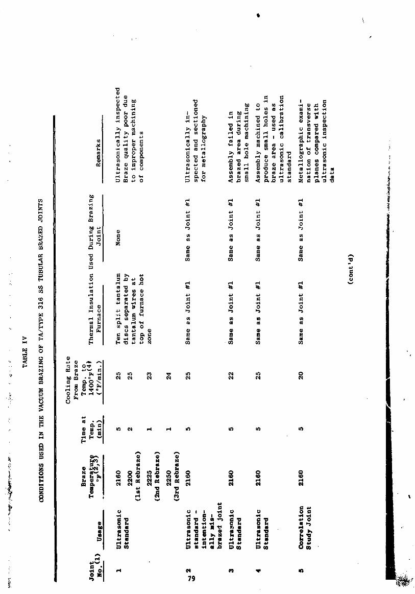
tb\
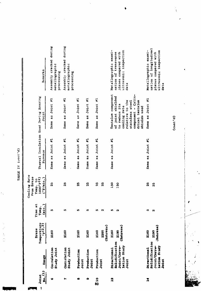
I)
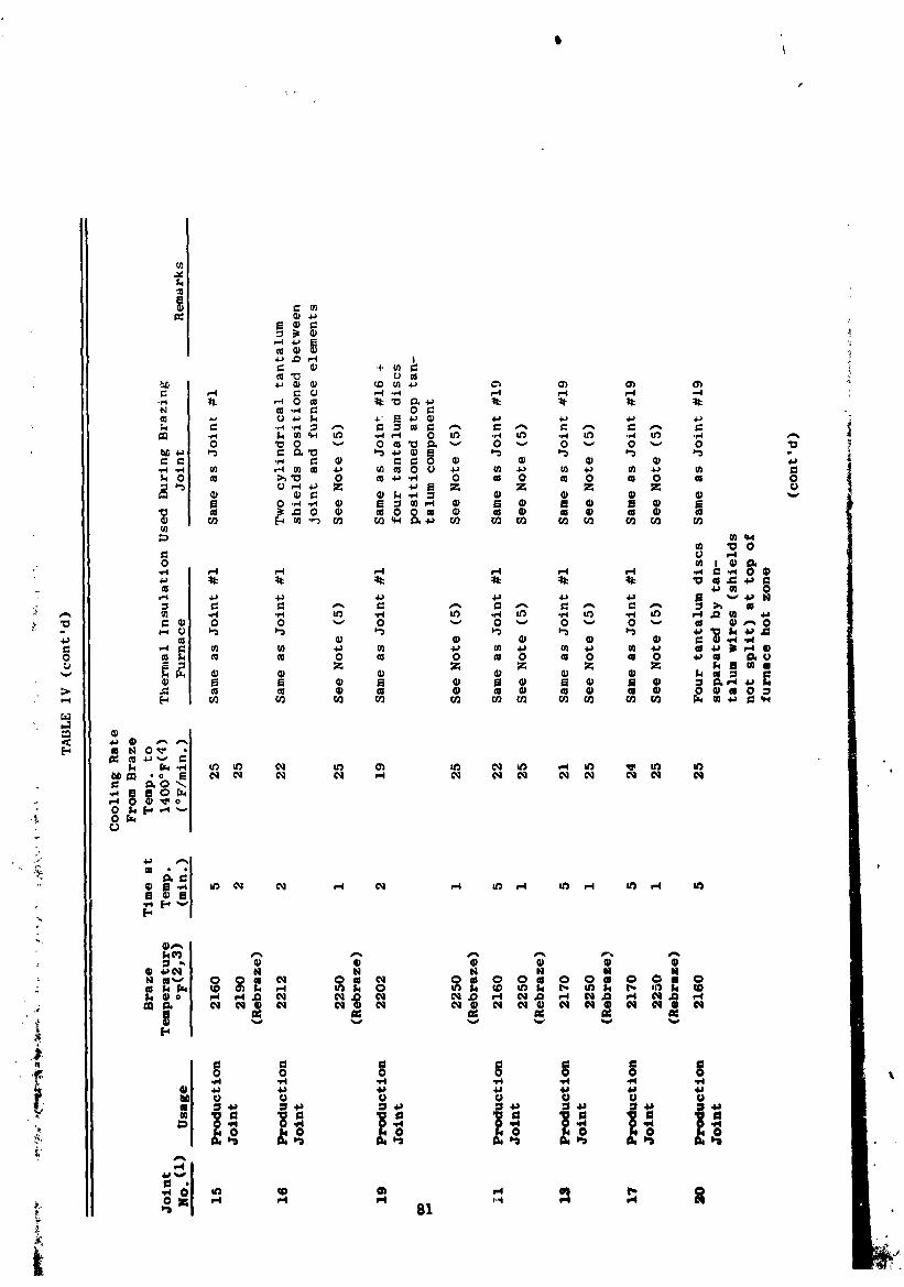
s
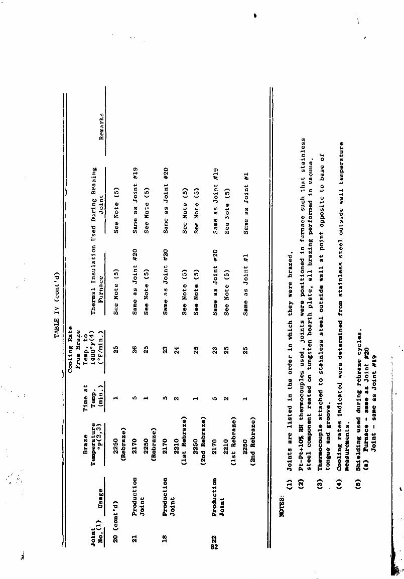
1971006113-100
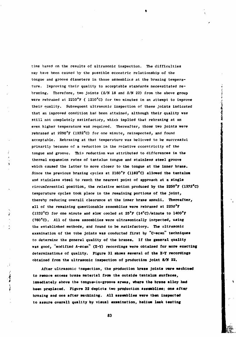
time based on the results of ultrasonic inspection. The difficulties
may have been caused by the possible eccentric relationship of the
tongue and groove diameters in those assemblies at the brazing tempera-
ture. Improving their quality to acceptable standards necessitated re-
brazing. Thereforej two joints (S/N 18 and S/N 22) from the above group
were rebrazed at 2210°F (1210°C) for two minutes in an attempt to improve
their _uallty. Subsequent ultrasonic inspection of these Joints indicated
that an improved condition had been attained, although their quality was
stili not completely satisfactory, which implied that rebrazlng at an i
even higher temperature was required. Thereafter, those two Joints were
rebrazed at 2250°F (1232°C) for one minute, relnspected, and found
acceptable. Rebrazlng at that temperature was bellowed to be successful
prlmarily because of a reduction in the relative eccentricity of the
tongue and groove. This reduction was attributed to differences in the
thermal expansion rates of tantalum tongue and stainless steel groove
which caused the latter to move closer to the tongue at the inner braze.
Since the previous brazing cycles at 2160°F (1182eC) allowed the tantalum
and stainless steel to reach the nearest point of approach at a single
circumferential position, the relative motion produced by the 2250°F (1232°C)
temperature cycles took place in the remaining portions of the Joint s
thereby reducing overall clearance at the inner braze annult. Thereafter#
all of the remaining questionable assemblies were rebrazed st 2250°F
(1232°C) for one minute and slow cooled at 25°F (14°C)/mlnute to 140OAF
(760°C). All of these assemblies were ultrasonically lnepectedj usingt
the established methods, and found to be satisfactory. The ultrasonic
examination of the tube Joints was conducted first by "C-scan" techniques
to determine the general quality of the brazes. If the general quality
was good, "modified A-scan" (X-Y) recordings were obtained for more exacting
determtnattoh_ of quality. Figure 31 shows several of the X-Y recordlng_
obtained from the ultrasonic inspection of production Joint 8/1/ 32.
After ultrssonic tnspection, the production braze Joints _tre machined
to r_o_e excess braze material from the outside tantalus surfaces,
immediately above the tongue-in-groove areas, where the brass alloy had
been preplsced. Figure 32 depicts two production assmsblies: one after
brazing and one after ms_hlning. All assemblies were then Inspected
to assure overall quality by visual examination, helium leek testing
83
1971006113-101
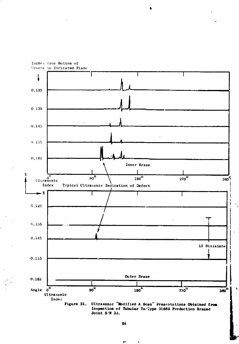
t
Inch,_..,Iro_ Bottom of
_'roo,.'eto Indicated Plane
L.0. 125 ....... " ]1.-_ .,
O. 135 4 _
().145
0 155
().165
Inner Braze
Yt_
0 90 ° 180 ° 270 ° 360 ¢UI Lrasonic
Index Typical Ultra:ionic Indication of Defect
=x ! i I
0.125
-I-, t
0. 135
O. 145
15 Divlsion_
I0.155
•. O. 165
t t IAngle 0 ° 90 ° 180 ° ?.70 ¢_ 3
Ultrasonic
Index
Figure 31. Ultrasonic "Jk)dlfled A Scan" Presentations Obtalned from
Inspection of Tubular Ta/'Type 3168/; Production BrazedJoint S/N 22.
84
1971006113-102
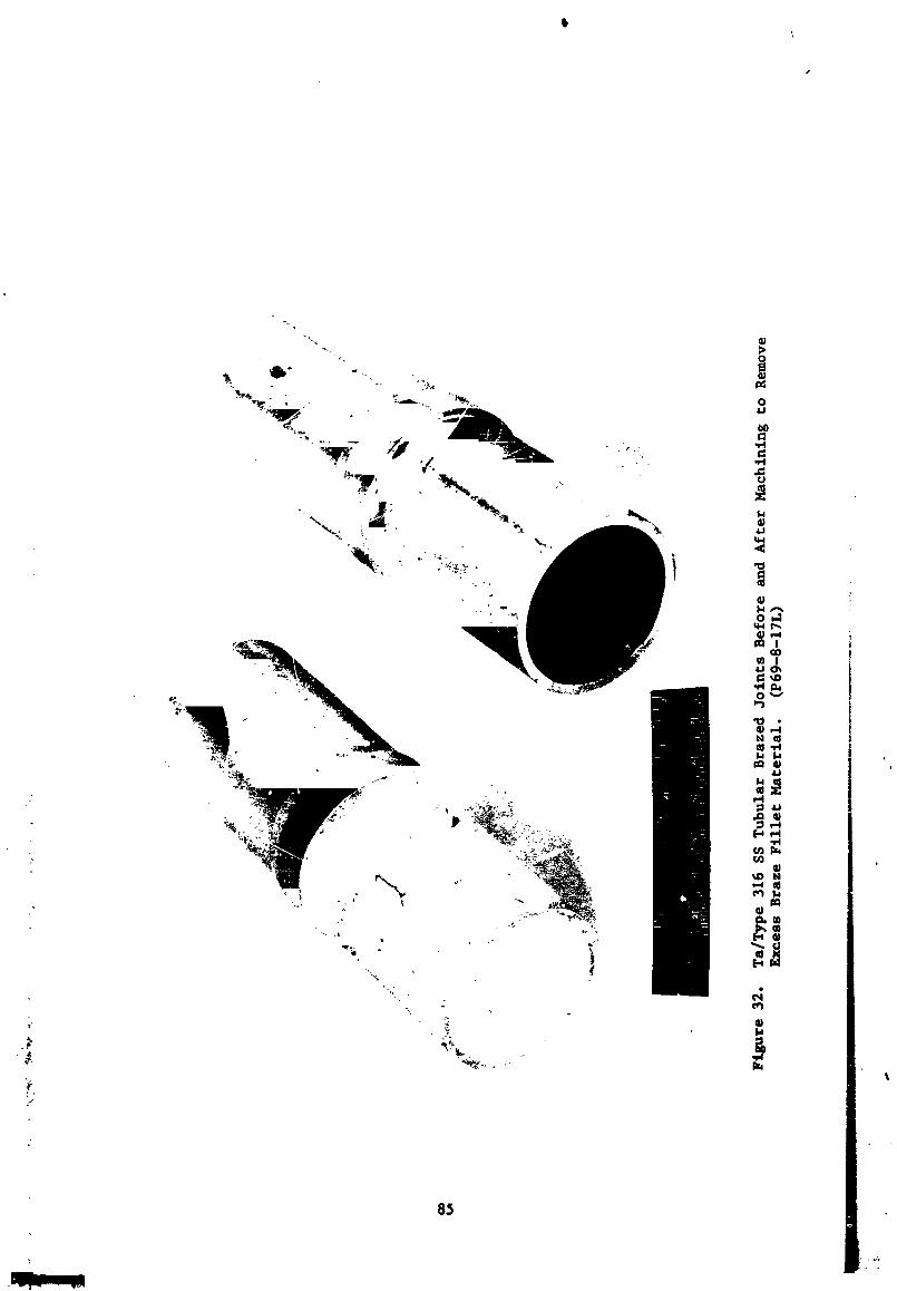
8_
1971006113-103
r
and dye penetrant ("Zyglo") inspection. The production joints were
cleaned and packaged for shipment a£ter those nondestructive tests had
been completed.
L
86
i •
1971006113-104
1
IV. C O N C L U S I O N S i
The experimentation to develop optimum methods for the brazing
and ultrasonic inspection of tubular, tantalum/Type 316 stainless steel,
tongue-in-groove design, transition joints produced several significant
conclusions:
1. The methods, developed for the brazing of tantalum-to Type
316 stainless steel in this program_ were shown to be capable
_ of producing tubular assemblies with minimal braze micro-
shrinkage. A number of such joints_ prepared by those developedJ-
2 techniques, will be subjected to appropriate evaluation testing
undez the direction of NASA-LRC. The results of that testing
will provide a meaningful definition of accepable brae character-
istics in future tubular assemblies.
2. The utilization of a slow cooling rate (25°F (14°C)/mlnute))
during braze solidification produced tantalum/Type 316 stain-
less steel tubular braze assemblies having superior character-
_ istics, in comparison with those evident in more rapidly cooled
: joints. Thus_ slower cooling rates produced lesser braze micro-
shrinkage, while not substantially increasing potentially
detrimental braze-base metal reaction zones in either the
tantalum or stainless steel joint components.
3. The tongue-in-groove design configuration for tubular brazed
joints requires modification to eliminate the nonuniform spacing
" in the annular braze cavities and thereby optimize brazement
_' characteristics. The concept believed to be moBt appropriateI
_ for achieving uniform spacings would incorporate an axially
tapered tongne-and-groove configuration. That geometry, coupled
_ with intercomponent guides to maintain concentricity of the
tantalum and stainless steel tubes_ would result in assemblies
t
¢
1971006113-105
r
having uniform and equal spacings of _ .y desired dimensions.
4. The ultrasonic inspection procedure and apparatus employed
were shown t.o have greater sensitivity than that required to
deteut those defects believed to be detrimental to the
strength of a brazed tantalum/Type 316 stainless steel tongue-
in-groove joint. For future inspections of tubular transition
joints of this tvF_, decreased sensitivity levels should be
utilized so that u:.iy the more severe defects would appeEtr
on the plan view presentation.
5. The developed ultrasonic inspection system has demonstrated
the capability for resolving individual defects in the brazed
areas. The system has sufficient power to permit inspection
of the inner braze annuli (i.e., at the inside of the tongue
and groove) at the same sensitivity levels used in scanning
the outer braze annuli,
6. Brazing of tubular assemblies, under conditions believed to be
conducive to directional braze solidificatlonj did not
enhance the brazing characteristics over those obtained by the
use of a slow cooling rate during braze freezing.
7. Limited elevated temperature tensile testing of brazed tongue-in-
groove sheet specimens indicated that the solidified J-8400
braze alloy could contain microshrlnkage occupying up to 25
percent of the total braze volume and still withstand stressesP
at 2000°F (1093°C)_ which would induce failure of the stainless
steel joint components. The braze alloy was also found to be I
resistant to crack propagation at that temperature under shear
loading conditions. Determination of the effects of different
braze mlcroshrinkage levels on the shear load carrying capa-
bility of tantalum/Type 316 stainless steel assemblies would
• require modification of the specimen doslgn configuration to
.... cause failures to occur in the braze material instead of the
" base material, l
/
88
1971006113-106
\
8. The as-brazed hardness of the J-8400 braze alloy exceeds that
of the tantalum and Type 31_ stainless steel parent metals by
a s.3stantial margin_ regaroless of the brazing thermal cycle _
employed. Further braze chemistry changes produce no apparent ,_
effects on the overall braze hardness. The extent of braze !_
constituent penetration into the stainless steel of tubular
assemblies is greater at the outside of the tongue-ln-groovethan at the inside, The formation _f an Intermetalllc phase
at tantalum/braze interfacesj early in tLe brazing cycle 3
limited the amount of further braze reactions in the tantalum
components.
J
h
• , ,.2
.!
_: 89
l
1971006113-107
\
V. REFERENCES
i. S. R. Thompson and J. Holowach_ "SNAP-8 Mercury Thermal Shock Test
of Bimetallic Joints"_ GESP-45_ R68NSP-I_ April I_ 1968.
2. S. R. Thompson_ "Mercury Thermal Shock Testing of 2-1/2-Inch-Diameter• t,
Bimetallic Joints for SNAP-8 Applications _ GESP-163_ R69NSP-3.
3. S. R. Thompson_ "Brazed Transition Joints for Liquid and Alkali
Metal Systems"_ GESP-160_ R69NSP-2.
4. Dr. Benjamin Wei, "Finite Element Analysis of SNAP-8 Multi-MaterialJolnts _ _eneral Electric Report No. TM9334-021.
9O
1971006113-108