DDX 9121b
Modular Partial Discharge (PD) & Radio Interference Voltage (RIV) Detector
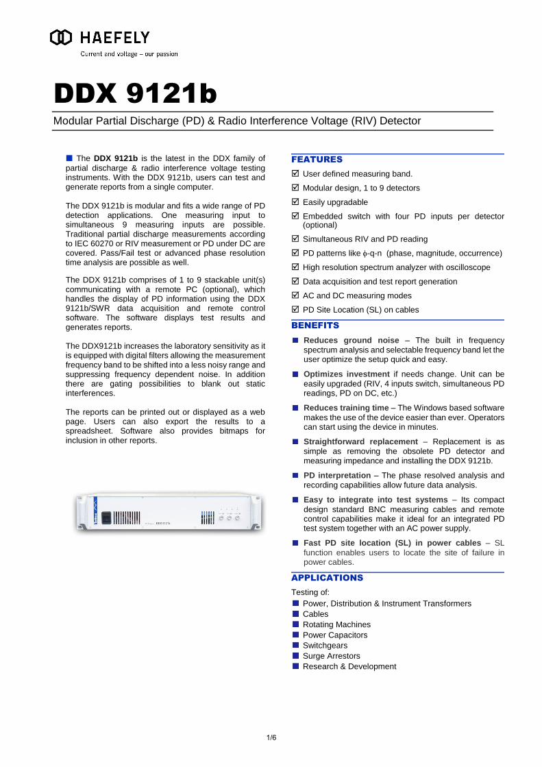
The DDX 9121b is the latest in the DDX family of
partial discharge & radio interference voltage testing instruments. With the DDX 9121b, users can test and generate reports from a single computer. The DDX 9121b is modular and fits a wide range of PD detection applications. One measuring input to simultaneous 9 measuring inputs are possible. Traditional partial discharge measurements according to IEC 60270 or RIV measurement or PD under DC are covered. Pass/Fail test or advanced phase resolution time analysis are possible as well.
The DDX 9121b comprises of 1 to 9 stackable unit(s) communicating with a remote PC (optional), which handles the display of PD information using the DDX 9121b/SWR data acquisition and remote control software. The software displays test results and generates reports. The DDX9121b increases the laboratory sensitivity as it is equipped with digital filters allowing the measurement frequency band to be shifted into a less noisy range and suppressing frequency dependent noise. In addition there are gating possibilities to blank out static interferences. The reports can be printed out or displayed as a web page. Users can also export the results to a spreadsheet. Software also provides bitmaps for inclusion in other reports.
FEATURES
User defined measuring band.
Modular design, 1 to 9 detectors
Easily upgradable
Embedded switch with four PD inputs per detector (optional)
Simultaneous RIV and PD reading
PD patterns like -q-n (phase, magnitude, occurrence)
High resolution spectrum analyzer with oscilloscope
Data acquisition and test report generation
AC and DC measuring modes
PD Site Location (SL) on cables
BENEFITS
Reduces ground noise – The built in frequency
spectrum analysis and selectable frequency band let the user optimize the setup quick and easy.
Optimizes investment if needs change. Unit can be
easily upgraded (RIV, 4 inputs switch, simultaneous PD readings, PD on DC, etc.)
Reduces training time – The Windows based software
makes the use of the device easier than ever. Operators can start using the device in minutes.
Straightforward replacement – Replacement is as
simple as removing the obsolete PD detector and measuring impedance and installing the DDX 9121b.
PD interpretation – The phase resolved analysis and
recording capabilities allow future data analysis.
Easy to integrate into test systems – Its compact
design standard BNC measuring cables and remote control capabilities make it ideal for an integrated PD test system together with an AC power supply.
Fast PD site location (SL) in power cables – SL
function enables users to locate the site of failure in power cables.
APPLICATIONS
Testing of:
Power, Distribution & Instrument Transformers
Cables
Rotating Machines
Power Capacitors
Switchgears
Surge Arrestors
Research & Development
1/6
USER ORIENTED INTERFACE
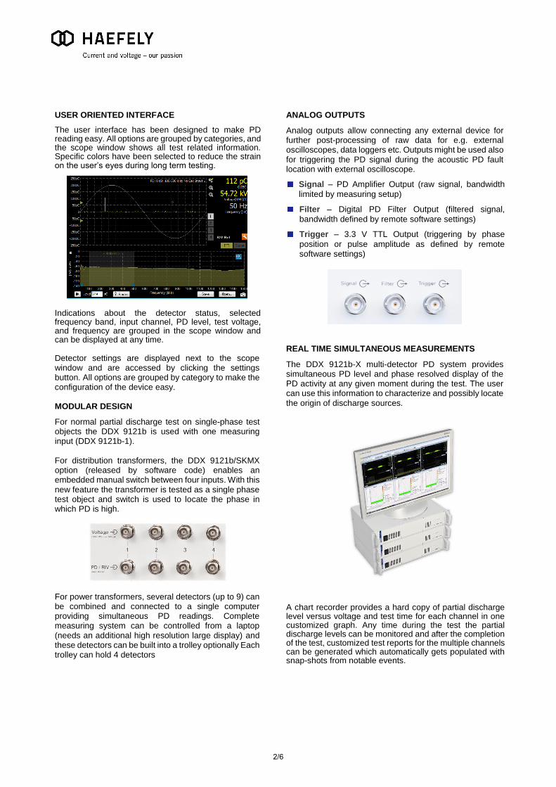
The user interface has been designed to make PD reading easy. All options are grouped by categories, and the scope window shows all test related information. Specific colors have been selected to reduce the strain on the user’s eyes during long term testing.
Indications about the detector status, selected frequency band, input channel, PD level, test voltage, and frequency are grouped in the scope window and can be displayed at any time. Detector settings are displayed next to the scope window and are accessed by clicking the settings button. All options are grouped by category to make the configuration of the device easy. MODULAR DESIGN
For normal partial discharge test on single-phase test objects the DDX 9121b is used with one measuring input (DDX 9121b-1). For distribution transformers, the DDX 9121b/SKMX option (released by software code) enables an embedded manual switch between four inputs. With this new feature the transformer is tested as a single phase test object and switch is used to locate the phase in which PD is high.
For power transformers, several detectors (up to 9) can be combined and connected to a single computer providing simultaneous PD readings. Complete measuring system can be controlled from a laptop (needs an additional high resolution large display) and these detectors can be built into a trolley optionally Each trolley can hold 4 detectors
ANALOG OUTPUTS
Analog outputs allow connecting any external device for further post-processing of raw data for e.g. external oscilloscopes, data loggers etc. Outputs might be used also for triggering the PD signal during the acoustic PD fault location with external oscilloscope.
Signal – PD Amplifier Output (raw signal, bandwidth
limited by measuring setup)
Filter – Digital PD Filter Output (filtered signal,
bandwidth defined by remote software settings)
Trigger – 3.3 V TTL Output (triggering by phase
position or pulse amplitude as defined by remote software settings)
REAL TIME SIMULTANEOUS MEASUREMENTS
The DDX 9121b-X multi-detector PD system provides simultaneous PD level and phase resolved display of the PD activity at any given moment during the test. The user can use this information to characterize and possibly locate the origin of discharge sources.
A chart recorder provides a hard copy of partial discharge level versus voltage and test time for each channel in one customized graph. Any time during the test the partial discharge levels can be monitored and after the completion of the test, customized test reports for the multiple channels can be generated which automatically gets populated with snap-shots from notable events.
2/6
SELECTABLE MEASURING BAND
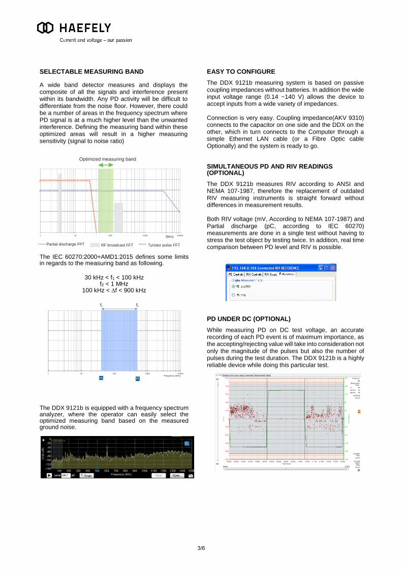
A wide band detector measures and displays the composite of all the signals and interference present within its bandwidth. Any PD activity will be difficult to differentiate from the noise floor. However, there could be a number of areas in the frequency spectrum where PD signal is at a much higher level than the unwanted interference. Defining the measuring band within these optimized areas will result in a higher measuring sensitivity (signal to noise ratio)
The IEC 60270:2000+AMD1:2015 defines some limits in regards to the measuring band as following.
30 kHz < f1 < 100 kHz
f2 < 1 MHz 100 kHz < f < 900 kHz
The DDX 9121b is equipped with a frequency spectrum analyzer, where the operator can easily select the optimized measuring band based on the measured ground noise.
EASY TO CONFIGURE
The DDX 9121b measuring system is based on passive coupling impedances without batteries. In addition the wide input voltage range (0.14 ~140 V) allows the device to accept inputs from a wide variety of impedances. Connection is very easy. Coupling impedance(AKV 9310) connects to the capacitor on one side and the DDX on the other, which in turn connects to the Computer through a simple Ethernet LAN cable (or a Fibre Optic cable Optionally) and the system is ready to go.
SIMULTANEOUS PD AND RIV READINGS (OPTIONAL)
The DDX 9121b measures RIV according to ANSI and NEMA 107-1987, therefore the replacement of outdated RIV measuring instruments is straight forward without differences in measurement results. Both RIV voltage (mV, According to NEMA 107-1987) and Partial discharge (pC, according to IEC 60270) measurements are done in a single test without having to stress the test object by testing twice. In addition, real time comparison between PD level and RIV is possible.
PD UNDER DC (OPTIONAL)
While measuring PD on DC test voltage, an accurate recording of each PD event is of maximum importance, as the accepting/rejecting value will take into consideration not only the magnitude of the pulses but also the number of pulses during the test duration. The DDX 9121b is a highly reliable device while doing this particular test.
0
20
40
60
80
100
120
1 10 100 1000 10000
Partial discharge FFT RF broadcast FFT Tyristor pulse FFT
Optimized measuring band
f(khz)
0
20
40
60
80
100
120
1 10 100 1000 10000Frequency (kHz)
f1 f2
3/6
DATA ACQUISITION & ANALYSIS
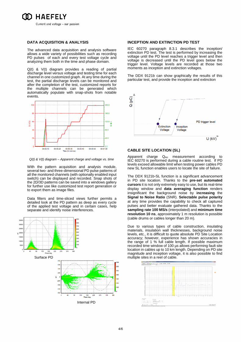
The advanced data acquisition and analysis software allows a wide variety of possibilities such as recording PD pulses of each and every test voltage cycle and analyzing them both in the time and phase domain. Q(t) & V(t) diagram provides a reading of partial discharge level versus voltage and testing time for each channel in one customized graph. At any time during the test, the partial discharge levels can be monitored and after the completion of the test, customized reports for the multiple channels can be generated which automatically populate with snap-shots from notable events.
Q(t) & V(t) diagram – Apparent charge and voltage vs. time
With the pattern acquisition and analysis module, several two- and three-dimensional PD pulse patterns of all the monitored channels (with optionally enabled input switch) can be displayed and recorded. Snap shots of the 2D/3D patterns can be saved into a windows gallery for further use like customized test report generation or to export them as image files.
Data filters and time-sliced views further permits a detailed look at the PD pattern as deep as every cycle of the applied test voltage and in certain cases, help separate and identify noise interferences.
INCEPTION AND EXTINCTION PD TEST
IEC 60270 paragraph 8.3.1 describes the inception/ extinction PD test. The test is performed by increasing the voltage until the PD level reaches a trigger level and then voltage is decreased until the PD level goes below the trigger level. Voltage levels are recorded at those two moments as inception and extinction voltages. The DDX 9121b can show graphically the results of this particular test, and provide the inception and extinction
CABLE SITE LOCATION (SL)
Apparent charge Qiec measurement according to IEC 60270 is performed during a cable routine test. If PD levels exceed allowable limit when testing power cables PD new SL function enables users to locate the site of failure. The DDX 9121b-SL function is a significant advancement in PD site location. Thanks to the pre-set automated cursors it is not only extremely easy to use, but its real-time display window and data averaging function renders insignificant the background noise by increasing the Signal to Noise Ratio (SNR). Selectable pulse polarity
at any time provides the capability to check all captured pulses and better evaluate gathered data. Thanks to the sampling rate 100 MS/s (interpolated) and minimum time resolution 10 ns, approximately 1 m resolution is possible
(cable drums or cables longer than 20 m). Due to various types of cable construction, insulating materials, insulation wall thicknesses, background noise levels, etc., it is difficult to quote absolute PD Site Location accuracy; however, experience has shown accuracies in the range of 1 % full cable length. If possible maximum recorded time window of 100 µs allows performing fault site location in cables up to 10 km length. Depending on PD site magnitude and inception voltage, it is also possible to find multiple sites in a reel of cable.
Surface PD
Internal PD
4/6
DATA EXPORT AND REPORTING
The reports are saved as HTML files containing graphs and charts. In addition, all data can be exported as comma separated values (CSV) format file for further analysis or for preparing highly customized test reports in other programs like MS Excel.
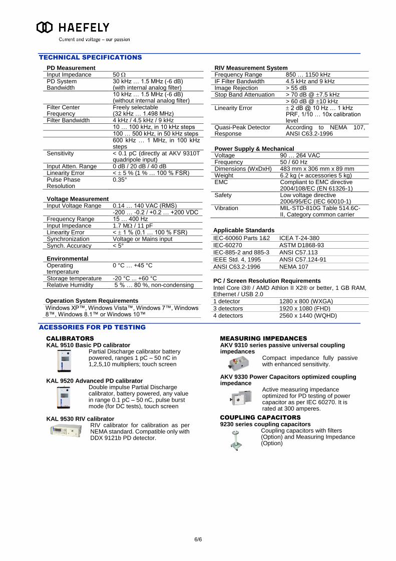
STANDARD CONFIGURATIONS
Simultaneous PD inputs
1 1 3 3 4 4 6 6 8 8
Non-simultaneous PD inputs Option DDX 9121b/SKMX
Opt 4
Opt 3
Opt 12
Opt 11
Opt 16
Opt 15
Opt 24
Opt 23
Opt 32
Opt 31
Simultaneous RIV inputs
Not 1 Not 3 Not 4 Not 6 Not 8
Non simultaneous RIV inputs Option DDX 9121b/SKMX
Not Opt 3
Not Opt 11
Not Opt 15
No Opt 23
Not Opt 31
PD on DC Option DDX 9121b/SKDC
Opt Opt Opt Opt Opt Opt Opt Opt Opt Opt
Phase resolve analysis
Yes Yes Yes Yes Yes Yes Yes Yes Yes Yes
Spectrum analyzer and scope
Yes Yes Yes Yes Yes Yes Yes Yes Yes Yes
Selectable measuring band
Yes Yes Yes Yes Yes Yes Yes Yes Yes Yes
Opt -> Option
Other configurations than the ones below in regards to number of detectors or options are available upon request.
RIV calibrator included in the device picture is required
OPTIONS
DDX 9121b/SKMX
DDX 9121b/FO
Software key to enable the 4 embedded non simultaneous inputs
Fiber optic adaptor to connect the DDX9121b and the computer
DDX 9121b/SKDC DDX 9121b/SKSL Software key to enable PD
measurement under DC Software key to enable Site Location
(SL) feature
COMPUTER AND TROLLEY
LAPTOP
DDX 9121b/TROLL Laptop with DDX 9121b software
preinstalled and configured. Windows 7 in English included.
Trolley on wheels for multi-detector configurations, trolley can be located in the test room and connected to the computer through fiber optic cables
Key code
Key code Key code
5/6
TECHNICAL SPECIFICATIONS
PD Measurement Input Impedance 50 PD System Bandwidth
30 kHz … 1.5 MHz (-6 dB) (with internal analog filter)
10 kHz … 1.5 MHz (-6 dB) (without internal analog filter)
Filter Center Frequency
Freely selectable (32 kHz … 1.498 MHz)
Filter Bandwidth 4 kHz / 4.5 kHz / 9 kHz 10 … 100 kHz, in 10 kHz steps 100 … 500 kHz, in 50 kHz steps 600 kHz … 1 MHz, in 100 kHz
steps Sensitivity < 0.1 pC (directly at AKV 9310T
quadripole input) Input Atten. Range 0 dB / 20 dB / 40 dB Linearity Error < 5 % (1 % … 100 % FSR) Pulse Phase Resolution
0.35°
Voltage Measurement Input Voltage Range 0.14 … 140 VAC (RMS) -200 … -0.2 / +0.2 … +200 VDC Frequency Range 15 … 400 Hz Input Impedance 1.7 M / 11 pF Linearity Error < 1 % (0.1 … 100 % FSR) Synchronization Voltage or Mains input Synch. Accuracy < 5°
Environmental Operating temperature
0 °C … +45 °C
Storage temperature -20 °C ... +60 °C Relative Humidity 5 % … 80 %, non-condensing
Operation System Requirements
Windows XP™, Windows Vista™, Windows 7™, Windows 8™, Windows 8.1™ or Windows 10™
RIV Measurement System Frequency Range 850 … 1150 kHz IF Filter Bandwidth 4.5 kHz and 9 kHz Image Rejection > 55 dB Stop Band Attenuation > 70 dB @ 7.5 kHz > 60 dB @ 10 kHz Linearity Error 2 dB @ 10 Hz … 1 kHz
PRF, 1/10 … 10x calibration level
Quasi-Peak Detector Response
According to NEMA 107, ANSI C63.2-1996
Power Supply & Mechanical Voltage 90 … 264 VAC Frequency 50 / 60 Hz Dimensions (WxDxH) 483 mm x 306 mm x 89 mm Weight 6.2 kg (+ accessories 5 kg) EMC Compliant to EMC directive
2004/108/EC (EN 61326-1) Safety Low voltage directive
2006/95/EC (IEC 60010-1) Vibration MIL-STD-810G Table 514.6C-
II, Category common carrier
Applicable Standards
IEC-60060 Parts 1&2 ICEA T-24-380
IEC-60270 ASTM D1868-93
IEC-885-2 and 885-3 ANSI C57.113
IEEE Std. 4, 1995 ANSI C57.124-91
ANSI C63.2-1996 NEMA 107
PC / Screen Resolution Requirements
Intel Core i3® / AMD Athlon II X2® or better, 1 GB RAM, Ethernet / USB 2.0
1 detector 1280 x 800 (WXGA)
3 detectors 1920 x 1080 (FHD)
4 detectors 2560 x 1440 (WQHD)
ACESSORIES FOR PD TESTING
CALIBRATORS
KAL 9510 Basic PD calibrator Partial Discharge calibrator battery
powered, ranges 1 pC – 50 nC in 1,2,5,10 multipliers; touch screen
KAL 9520 Advanced PD calibrator Double impulse Partial Discharge
calibrator, battery powered, any value in range 0.1 pC – 50 nC, pulse burst mode (for DC tests), touch screen
KAL 9530 RIV calibrator
RIV calibrator for calibration as per NEMA standard. Compatible only with DDX 9121b PD detector.
MEASURING IMPEDANCES
AKV 9310 series passive universal coupling impedances
Compact impedance fully passive with enhanced sensitivity.
AKV 9330 Power Capacitors optimized coupling impedance
Active measuring impedance optimized for PD testing of power capacitor as per IEC 60270. It is rated at 300 amperes.
COUPLING CAPACITORS
9230 series coupling capacitors Coupling capacitors with filters
(Option) and Measuring Impedance (Option)
6/6

![Loan Agreement No: [ID-P245] - FB No: [CPC/JICA/ICB/03A/19 ...€¦ · (of 5 pC and above) as per IEC 60270 through Partial Discharge (PD) monitoring system], different gas compartment,](https://static.cupdf.com/doc/110x72/5e8ee1aa2b3c01322c5d6043/loan-agreement-no-id-p245-fb-no-cpcjicaicb03a19-of-5-pc-and-above.jpg)