S540
MEASUREMENT OF SURFACE TENSION
By N. Ernest Dorsey
ABSTRACT
This paper (a) presents a brief survey of the more important of the methods
which have been employed in the measurement of surface tension, (&) calls
attention to some of the more important facts vrhich must be kept in mind by
one wishing to succeed in such measurements, (c) indicates certain errors
which are frequently made and shows how they may be avoided, and (d) gives
the working equations that are applicable to the methods considered. Abibliography of more than 100 selected papers is appended. In each instance
the purpose for which the reference was selected is indicated.
CONTENTS
Page
I. Introduction 563 III. MII. General remarks 565
1. Surface tension 565
2. Negligible quantities— 566
3. Purity 566
4. Contact angle 568
5. Mathematical 570
6. Notation 571
7. Reservoir correction— 572
[II. Methods of measurement— 573
1. Capillary tubes 574
2. Virtual capillary tube
(method of Sentis)- 576
3. Vertical plates 577
4. Plate and cylinder 578
5. Small pendant drops.. 579 IV. B6. Large pendant drops— 579
Methods of measurement
—
Continued.
7. Sessile drops and bub-
bles
8. Jaeger's method9. Drop weight
10. Pull of vertical film_.
11. Pull on vertical plate.
12. Pull on ring
13. Adhesion plate
14. Pull on sphere
15. Oscillating drops andbubbles
16. Vibrating jets
17. Ripples
Pago
580
581
583
586
586
586
587
588
589
590
592
I. INTRODUCTION
Every set of measurements connecting the curvature of a liquid
surface at a given point with the difference in the hydrostatic pres-
sure on the two sides of the surface at that point; every set of
observations connecting the velocity of propagation of a deforma-
563
564 Scientific Papers of the Bureau of Standards [Voi.zt
tion over the surface of a liquid with the nature of the deformation,
the size of the liquid mass, the undeformed shape of the surface,
the density of the liquid, and the forces that enter into the phenome-
non ; and every set of observations connecting the frequency of oscil-
lation of a liquid mass v^ith its size, undisturbed form, and the
forces that enter into the problem, may be used to determine the
value of the surface tension of the surface concerned. The numberof methods is ahnost unlimited; and in point of fact the numberthat are more or less workable in practice, and even the number which
have been actually used, is great, and the latter is being increased
continually.
Such a wealth of available methods is ideal for the detection and
the elimination of constant experimental errors, but it is also fruitful
of great discordance when due attention is not paid to such errors.
In the past, surface-tension measurements have frequently been
marked by excessive care to secure a high reproducibility, accom-
panied by scant attention to the possible presence of constant errors
and to the real significance of the quantity which is reproduced.
There is a great need for a careful study of the various methods in
order to determine {w) the proper interpretation of the quantity
which is determined by each, (fi) the magnitude of the errors which
are introduced by known small departures from the ideal conditions
upon which the interpretation rests, and {c) the limits within which
each of the several methods are trustworthy. Ferguson (21)^ has
started upon such a program. His work will be followed with muchinterest. Unfortunately, the mathematical discussions in some of
his earlier papers have been marred by errors (66, 78, 79) ; it is
hoped that all such errors will be corrected as the work progresses.
The object of the present paper is much less ambitious. Its aimis to present a brief survey of the more important of the methods
which have been employed, to call attention to some of the moreimportant facts which must be kept in mind by one wishing to suc-
ceed in such measurements, to indicate certain errors which are fre-
quently made and to show how they may be avoided, and to give
the working equations that are applicable to the methods whichare here considered. The derivations of the equations and direc-
tions for the construction and use of the necessar^^ apparatus will
have to be sought in other places, to the more important of whichreferences will be given. The list of references does not pretend to be
complete but is intended merely to direct the reader to one or moreof the sources from which the required information can be obtained
most satisfactorily.
iThe figures given in parentheses here and throughout the text relate to the refereuce
numbers in the bibliography given at the end of this paper.
Darsey] Measurement of Surface Tensioii 565
II. GENERAL REMARKS
1. SURFACE TENSION
The term " surface tension " conveys a fictitious, thougli very valu-
able, picture of the phenomenon under consideration. In the body
of a liquid the molecular attractions acting upon an element of tlie
liquid are, on the whole, completely balanced ; the element is pulled
as strongly in one direction as in another. As the surface is ap-
proached this balance is destroyed. Near the surface the element is
pulled more strongly toward the liquid than toward the other mediumfrom which the surface separates the liquid, or else the reverse is
true. This lack of balance in the molecular forces acting upon the
elements of the liquid is what gives rise to the property that we call
.surface tension. The lack of balance, and consequently the surface
tension, depends upon the properties of both of the media of which
the surface is the common boundary. Surface tension is not a prop-
erty of one medium, but is the joint property of two media. Whenone speaks of the surface tension of a particular liquid, what is meant,
or at least what should be meant, is the surface tension of the liquid
in contact with its own pure vapor at the same temperature. Actually
the surface tension of the interface separating a liquid from a gas
or vapor depends but little upon the nature of the latter, provided
that it does not react chemically with the liquid, and that certain
exceptional conditions are excluded.
When we enlarge a clean liquid surface we do not stretch it in anyproper sense of this term ; we merely bring into being an additional
area of the same kind of surface as we had before. When we speak
of a surface tending to contract under the action of its surface ten-
sion we do not mean that the particles in the surface tend to crowdnearer together while remaining in the surface, but that they tend
to withdraw from the surface into the interior of the liquid. As weare concerned with a condition of stable equilibrium it is obvious
that they can not so withdraw unless provision is made for a cor-
responding decrease in the area of the surface.
The range through which the forces are unbalanced is negligibly
small as compared with the smallest difference in length which wecan experimentally measure under the conditions with which we are
here concerned. All the equations employed in the reduction of
surface-tension measurements are based upon the assumption that
the transition layer in which the forces are unbalanced is of neg-
ligible thickness. Should conditions ever arise in which this assump-tion is not justified, then either we must completely reconsider the
equations, taking into account the variation in the forces as we pass
through the surface layer, or we must change the scale of our opera-
566 Scientific Papers of the Bureau of Standards iVoi.it
tions in such a maimer that the thickness of the transition layer be-
comes negligible in comparison with the smallest length which wecan measure upon the revised scale. Indeed, unless our scale is so
coarse that the transition layer is negligibly thin, the concept of a
"surface" tension loses its significance.
2. NEGLIGIBLE QUANTITIES
Although frequently forgotten, it should be remembered that the
terms " negligible " and " small " are purely relative. To say that
something is negligible or small, without indicating either directly or
by implication anything with which it is thus compared, is to talk
nonsense. It can be negligible or small only in comparison with
something else of the same kind. It is especially necessary to keep
this clearly in mind when considering the equations applicable to
surface-tension phenomena. With few exceptions the working equa-
tions are approximate only and are validly applicable only under
the condition that certain lengths are negligible with reference to
certain other lengths involved in the phenomenon. It makes no
difference how small the first length is, the equation is not applicable
unless the comparison length is so great that the first is negligible
in comparison with it. By this we mean that in any sum or difference
of the two lengths the first may be neglected without changing the
value of the sum or difference by an amount that is experimentally
significant. It does not mean that when the first length occurs as
the numerator of a fraction of which the second is the denominator
that this fraction can always be ignored; that depends upon the
connection in which the fraction occurs. Will the value of the sumor other function in which it enters be changed by a significant
amount if this fraction is made zero ? If so, then the fraction is not
negligible with reference to the other terms that enter into the
function.
3. PURITY
Although the purity of the materials used is of importance, it
should be borne in mind that it is the purity of the surface separat-
ing the juxtaposed fluids that must primarily be considered. This
is quite a different thing from the chemical purity of the materials
in bulk. Exceedingly small amounts of physical contamination mayaffect the surface most seriously. Whatever tends to lower the sur-
face tension will tend to accumulate in the surface. For this reason,
other things being the same, the higher values of the surface tension
are worthy of the greater confidence.
For the same reason the concentration of the surface of a solution
is, in general, different from that of the solution in bulk. When
Dorsey] MeasxLremcnt of Surface Tension 567
a fresh surface is formed, diffusion sets in tending to bring about
this difference in concentration. Consequently, the properties of a
surface bounding a sohition should be expected to depend upon the
age of the surface. It is merely a question of whether the change
takes place slowly enough for us to be able to detect it with the meansat our disposal. In some cases it does take place so slowly. Thus,
Rayleigh (59) found that the tension of a freshly formed surface
separating a soap solution from air differs very little from that of
an air-water surface, but decreases markedly within a few seconds.
The explanation is to be sought in the progressive accumulation of
soap in the superficial layers. More recently du Noiiy (50a, 50b)
and Johlin (35a) have shown that the surface of many colloidal
solutions attain equilibrium very slowly. The tension of the sur-
face may continue to decrease for hours after the surface is first
formed, and the final value of the tension may be as much as 50 per
cent lower than the initial value. This is explained by the pro-
gressive change in the concentration of the surface layer.
In the case of pure fluids no such diffusion phenomena can exist,
and it is very probable that the rearrangement of the molecules
attendant upon the formation of a fresh surface takes place too rap-
idly to be detected by any means that has yet been proposed. Wemight likewise anticipate that the time required for the interface of
two pure fluids to become saturated with each would be too short
to be detected by any of our usual procedures. This also seems
to agree with experience. Nevertheless, it is well to take pains to
insure such saturation before making measurements.
When a surface is exposed to the air it gradually becomes con-
taminated and its properties progressively change. Thus Schmidt
(65) observed that the superficial viscosity of mercury increased
manyfold in the course of a few hours after it was first exposed to
the air. The surface tension is likewise affected by the contamina-
tion of the surface—it is reduced. The progressive effect of con-
tamination is of the same sign as that of changing concentration
—
it is difficult to separate the two effects.
When one of the fluids separated by the surface is a gas, one wouldanticipate, from the great disparity in the density of a gas and a
liquid, that under ordinary conditions the tension of the surface
would be very slightly affected by the nature of the overlying gas
and would be still less affected by the solution of the gas in the
liquid. This appears to be borne out by experiment (100). On the
other hand, when a liquid is near its critical point and is in con-
tact with an inert gas under high pressure, it seems possible that the
solution of the gas in the liquid might produce a considerable effect.
568 Scientific Papers of the Bureau of Standards ivoi. ti
4. CONTACT ANGLE
In many surface-tension problems it is necessary to know the
angle at which the liquid surface meets a given solid wall. But the
intersection of two surfaces defines two plane angles; which shall
we take as the angle of contact of the liquid with the wall? The
acute angle between the tangent to the surface at the point of
contact and the tangent to the wall at the same point, each drawn
in the plane that is normal to the line of contact, might be taken
as defining the angle of contact; but physical considerations reveal
that this is not satisfactory. There are two fluids to be considered
and two angles are at our disposal. One is to be regarded as the
angle of contact of the surface of fluids with the wall, and the
other as the angle of contact of fluid2 with the wall. Either angle
might be chosen as the angle of contact of fluids, the other being
that of fluidg. But the more logical choice appears to be that
which is universally accepted; namely, the angle of contact of
fluidi with the wall is the angle of the limiting wedge of fluids
that is bounded by the fluidi-fluidg surface and the fluids-wall
surface. It may have any value between and 180°, each included.
If the wall has an absolutely sharp edge at the line of contact, the
concept of a tangent to the wall at and across the line of contact
loses its significance, and consequently the significance of an angle
of contact is likewise lost. But if the edge is rounded, no matter
how short its radii of curvature, provided that they are long as
compared with the range of molecular forces, the concept holds.
In practice, an edge is never infinitely sharp. If the surface were
free from all other constraints, probably it would adjust itself
in such a way that the angle of contact would be always the same
for the same surface and wall, temperature and other pertinent
conditions being the same. This equilibrium angle of contact is
called the " contact angle " of the fluid with the wall under the
existing conditions. But all who have worked with mercury ma-nometers know that a liquid surface may be subjected to constraints
that appear closely akin to frictional resistance of the kind charac-
teristic of the sliding of solids over solids. Under the action of
such constraints the surface can not adjust itself as it otherwise
would, and the angle of contact may take any one of a range of
values. It is desirable to distinguish between the existing angle
of contact and that particular angle of contact which is charac-
teristic of equilibrium in the absence of such constraints as we haveconsidered. For the latter, which is probably a characteristic of
the fluids and the wall, we shall reserve the term " contact angle "
;
the others will be designated as angles of contact.
Doi-aoi/] Measurement of Surface Tension 569
The existence of constraints is to be expected. An advance of the
line of contact is necessarily accompanied by the replacing of an
intimate contact of the solid and one fluid by an intimate contact of
the solid and the other fluid. If there is any adhesion between the
solid and the fluids, the replacement will involve irreversible effects,
and constraints of the kind considered will result ; and there is always
adhesion.
There is, however, one case in which the constraint will be absent.
This is when one of the fluids adheres to the solid so strongly that
it is not replaced by the second, but the second merely flows over
a thin laj^er of the first which continues to be attached to the solid.
We thus have in reality merely one surface—that of the fluid-fluid
boundary—the solid merely serving as a support to the thin layer.
If the thickness of the adhering layer exceeds the range of the
molecular forces, then, except for viscous effects, which merely delay
the attainment of equilibrium, there is perfect freedom of motion,
and the apparent contact angle is zero. If the thickness is less than
the range of molecular forces, then the apparent contact angle may be
different from zero but will be definite if sufficient time is given for
the layer to drain to its equilibrium thickness. Before such drain-
age is complete the angle may be expected to vary as the layer thins.
In this case, also, the motion of the boundary surface over the solid
will be quite free, but the freedom will decrease as the time required
for drainage increases. The drainage will be affected not only by the
viscosity of the fluid forming the layer, but also by that of the other
fluid which presses it against the solid. In all these cases the actual
angle of contact of the fluid-fluid surface with the solid is to be
found at the free end of the layer far beyond the region with whichwe are primarily concerned.
Any change in the surfaces, whether due to contamination or
other cause, may be expected to cause a change in the angle of con-
tact, except in the single case in which it is zero as the result of the
solid being covered by a layer of fluid so thick that the molecular
forces of the solid can not penetrate it.
The main facts brought out by the large amount of experimental
work that has been done in the study of angles of contact justify
these conclusions. It has been found that in many cases the solid
surface can be so prepared that the liquid will truly wet it (81, 64),
will slide freely over the surface ; under these conditions the effective
angle of contact is actually zero, the free surface passing by imper-
ceptible degrees into the exceedingly thin film which remains coating
the solid and extending to points far beyond the apparent line of
contact. But when surfaces so prepared are allowed to dry, the
liquid may then meet them at a finite angle and may no longer slide
10712°—26 2
570 Scientific Papers of the Bureau of Standards [voi. ti
freely over them (64). In other cases it seems impossible to prepare
a given surface in such a way that the liquid can truly wet it (12).
Generally, in such cases the liquid will not move freely over the solid,
and the angle of contact will be both finite and variable; but occa-
sionally the motion may be free, and then the contact angle though
finite is constant. For any solid and any liquid an inconstant finite
angle appears to be possible, but the insuring of a zero or other
constant angle is in many cases very difficult if not impossible.
For these reasons it is desirable to choose for the measurement of
surface tension such methods as do not require a knowledge of the
value of the angle of contact. Methods involving a knowledge of the
angle of contact may, however, be safely used if care is taken to
insure that the solid is perfectly wetted by the liquid at the time that
the measurement is made. Or, if the liquid moves perfectly freely
over the wall, although it does not wet it, provided that the angle
of contact is certainly known to the necessary precision. A measure-
ment of the angle of contact under the conditions of observation in
surface-tension measurement involves many difficulties, not the least
of which is the fact that the angle required is that made by the last
infinitesimal element of the surface. To measure the angle under one
set of conditions and to use it under another involves the unsound
assumption that it is necessarily the same in both cases. (Quincke
(55, 56), Volkmann (82, 83, 84, 85, 86, 87), Anderson and Bowen
(4), Bosanquet and Hartley (T), Ablett (1), Ferguson (23), Dorsey
(12),Devaux (95,96).)
5. MATHEMATICAL
Of the many mathematical discussions of the problems that arise
in connection with the measurement of surface tension, the most
satisfactory and complete is probably that of Verschaffelt (78, 79,
80). It should be noted that his notation differs from those most
commonly used. He deduces general equations which can be readily
adapted to the various particular cases that arise in practice, but in
only a few instances does he give an equation in the final form re-
quired for the reduction of observations.
As the derivations of the equations applicable to the several
methods which we shall consider are readily available elsewhere, it
will suffice to give here the final equations and references to where
their derivations may be found. The equations given will not always
be of the same form as those given in the corresponding citations
but will be derivable therefrom. The change in form has been madefor the purpose of securing greater uniformity.
Dorsou] Measurement of Surface Tension 571
6. NOTATION
Throiigliout the remainder of this j^aper the following notation
•will be used; when additional symbols are required they will be
explained as introduced.
Subscripts.—Whenever it is necessary to distinguish between the
two fluids of which the surface is the interface it will be done by
means of the subscripts 1 and 2. When the problem involves a ref-
erence to a portion of the surface which is horizontal and flat, the
subscript 1 will be used to denote that liquid Avhich lies below that
portion of the surface. When a surface of revolution is under con-
sideration the subscript 1 will be used to denote that liquid which is
below the vertex of the surface. (See figs. 1, 2.) It will be noticed
in Figure 1 that the fluid which is denoted by 1 when the meniscus
in the tube is being considered is the same as that denoted by 2 whenthe suspended drop is being discussed. Quantities pertaining to the
vertex of a s'urface of revolution will be distinguished, as necessary,
by means of the subscript 0.
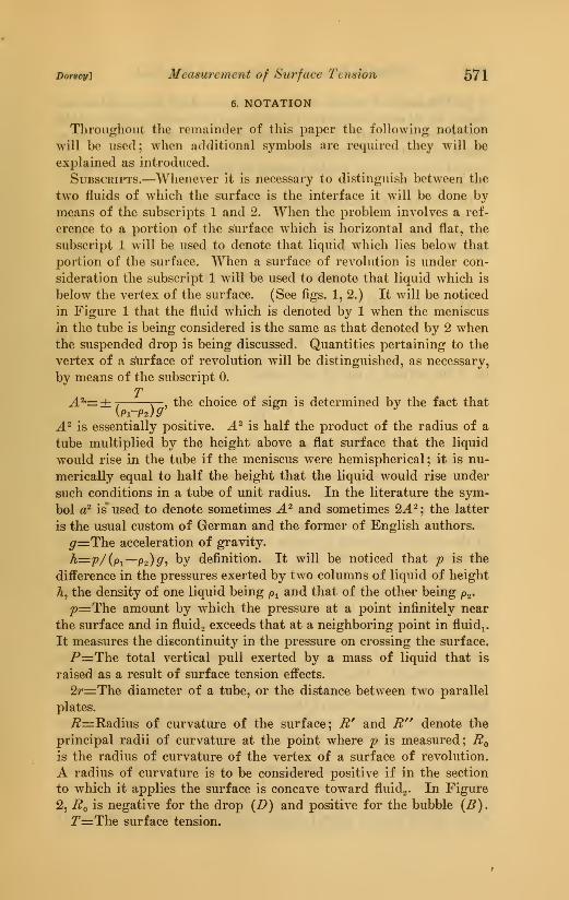
TA^^±-, X— , the choice of sign is determined by the fact that
A^ is essentially positive. A^ is half the product of the radius of a
tube multiplied by the height above a flat surface that the liquid
would rise in the tube if the meniscus were hemispherical; it is nu-
merically equal to half the height that the liquid would rise under
such conditions in a tube of unit radius. In the literature the sym-
bol a^ is* used to denote sometimes A^ and sometimes 2^.^; the latter
is the usual custom of German and the former of English authors.
^=:The acceleration of gravity.
h^p/(p^—P2)g', by definition. It will be noticed that p is the
difference in the pressures exerted by two columns of liquid of height
h, the density of one liquid being /o^ and that of the oth^- being p^-
/>=:The amount by which the pressure at a point infinitely near
the surface and in fluids exceeds that at a neighboring point in fluidi.
It measures the discontinuity in the pressure on crossing the surface.
P=The total vertical pull exerted by a mass of liquid that is
raised as a result of surface tension effects.
2r=r:The diameter of a tube, or the distance between two parallel
plates.
/?=Radius of curvature of the surface; i?' and ^" denote the
principal radii of curvature at the point where p is measured; Eqis the radius of curvature of the vertex of a surface of revolution.
A radius of curvature is to be considered positive if in the section
to which it applies the surface is concave toward fluidg. In Figure
2, Bq is negatiA'C for the drop (Z>) and positive for the bubble {B).
2^=The surface tension.
572 Scientific Papers of the Bureau of Standards \_vol ti
^=The angle of contact of the surface of a fluid with another sur-
face. In all cases considered in this paper the second surface will be
that of a solid wall. In every case it is necessary to indicate to
which of the two fluids 6 applies.
P=The density; p^ is the density of fluids and p^ that of fluidj.
(See figs. 1, 2.)
In dealing with surfaces of revolution, axes of coordinates will
be laid so that the origin is at the vertex, the axis of X is in the
tangent plane, and the positive direction of Y is upward. Other
cases, of which there are but few, will be considered as they arise.
7. RESERVOIR CORRECTION
The fundamental equation in capillarity is
v-t[1,+-^\ (1)
or, if the surface is one of revolution,
whence T may be obtained at once if p^ and Rq^ or ^, ^', and R'^
are known.In many cases the pressures po and p are derived from the observed
height of a column of liquid. In practice, the vertical height of the
column is usually measured from the vertex of the surface ofa liquid
contained in a relatively large reservoir. Unless the sectional area
of the reservoir exceeds a certain value, depending upon the liquid,
the surface at the vertex will be appreciably curved. This curva-
ture will introduce a pressure (equation 2). The total pressure cor-
responding to the observed height will be the sum of the pressure
due to the curvature, taken with the proper sign, and the hydrostatic
pressure due to the observed column. It is customary to express
the pressure due to the curvature in terms of the equivalent hydro-
static column and to regard it as a correction to be added to the
observed height. This correction may be denoted by the symbol he.
Richards and Carver (64) have experimentally investigated the
amount of this correction in the case of cylindrical reservoirs of cir-
cular section of radius r and have prepared a curve giving the values
of h^/A-^^ corresponding to various values of r/A^ lying between
1.25 and 4.30. They use the symbol a to denote A^. An optical
method was used for measuring the curvature of the surface at the
vertex. Rayleigh (62), and also Verschaffelt (79), have deduced
expressions by means of which the value of h^/A may be computed
when r/A is known, provided that r/A amounts to at least several
Dorsey] Measurement of Surface Tension 573
units. Rayleigh gives a table of values of he/A corresponding to
integral values of r/A lying between G and 10. Values may also be
computed from the exact tables prepared by Bashforth and Adams(5), either directly or from the table which was prepared from tliese
tables by Sugden (70). The values given in Table 1 were obtained
from Sugden 's table ; they essentially agree with the values given byRayleigh and b}' Richards and Carver.
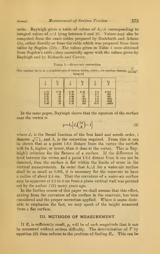
Table 1.
—
Reservoir correction
T[The capillary rise ^o in a cylindrical tube of circular section, radius r, the capillary constant, / v »
being A^]
T /ic r h^ r fto
A A A A A A
1.75 0.76 3.25 0.19 6.0 0.0152.00 .59 3.50 .15 6.5 .0092.25 .46 4.00 .09 7.0 .0062.50 .37 4.50 .054 8.0 .00232.75 .30 5.00 .035 9.0 .00093.00 .24 5.50 .022 10.0 .00034
In the same paper, Rayleigh shows that the equation of the surface
near the vertex is
2/= /tc}/o(jj-lj (3)
where Jo is the Bessel function of the first kind and zeroth order, i
denotes y — i, and he is the correction required. From this it can
be shown that at a point 1.8J. distant from the vertex the surface
will lie Ac higher, or lower, than it does at the vertex. This is Ray-
leigh's criterion for the flatness of a surface. If the difference in
level between the vertex and a point 1.8^ distant from it can not be
detected, then the surface is flat within the limits of error in the
vertical measurements. In order that h^/A for a water-air surface
shall be as small as 0.001, it is necessary for the reservoir to have
a radius of about 2.4 cm. That the curvature of a water-air surface
may be apparent at 2.5 to 3 cm from a plane vertical wall was pointed
out by the author (12) many years ago.
In the further course of this paper we shall assume that this effect,
arising from the curvature of the surface in the reservoir, has been
considered and the proper correction applied. Where it seems desir-
able to emphasize the fact, we may speak of the height measured
from a flat surface.
III. METHODS OF MEASUREMENT
If ^o is sufficiently small, po will be of such magnitude that it can
be measured without serious difficulty. The determination of T byequation (2) then reduces to the problem of finding Rq. This can be
574 Scienti-fic Papers of the Bureau of Standards {voi. tt
done in some cases by means of optical methods (64) ; in other cases
it may be determined by the measurement of a photograph or of an
enlarged projection of the surface (8, 15, 91) ; but in most cases
it is more satisfactory to deduce the value of Ro from some other
length that is more amenable to direct measurement. This is the
usual procedure in the method of capillary tubes.
1. CAPILLARY TUBES
For capillary tubes the value of Eq is deduced from the radius
of the tube and the properties of the fluids. In this way equation
(4) is obtained. In this equation ^^ denotes the angle of contact of
the lower fluid (fluidi) with the wall.
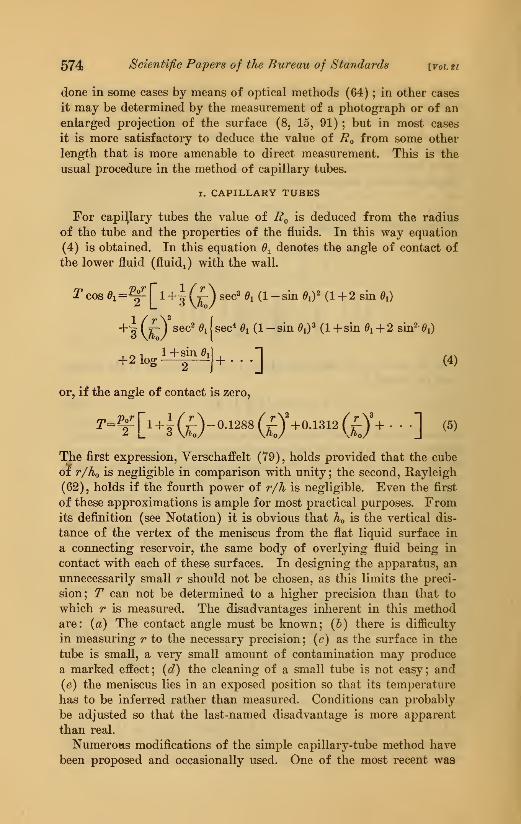
^cos ^i=^ri+^ (^) sec^ di (1 -sin e,y (1 +2 sin d^)
+-i ("^Ysec^ ^ijsec* 6^ (1 -sin ^i)^ (1 +sin ^i + 2 sin^-^i)
+2 1ogi±f^j+...] (4)
or, if the angle of contact is zero,
The first expression, Verschaffelt (79), holds provided that the cube
of r/ho is negligible in comparison with unity ; the second, Rayleigh
(62), holds if the fourth power of r/h is negligible. Even the first
of these approximations is ample for most practical purposes. Fromits definition (see Notation) it is obvious that ho is the vertical dis-
tance of the vertex of the meniscus from the flat liquid surface in
a connecting reservoir, the same body of overlying fluid being in
contact with each of these surfaces. In designing the apparatus, an
unnecessarily small r should not be chosen, as this limits the preci-
sion; T can not be determined to a higher precision than that to
which r is measured. The disadvantages inherent in this methodare: (a) The contact angle must be known; (h) there is difficulty
in measuring r to the necessar}^ precision; (c) as the surface in the
tube is small, a very small amount of contamination may produce
a marked effect; (d) the cleaning of a small tube is not easy; and(e) the meniscus lies in an exposed position so that its temperature
has to be inferred rather than measured. Conditions can probably
be adjusted so that the last-named disadvantage is more apparent
than real.
Numerous modifications of the simple capillary-tube method have
been proposed and occasionally used. One of the most recent was
Dorsc!/] Measurement of Surface Tension 575
proposed by Ferguson (20). He suggests applying a pressure to the
capillary column so as to drive the meniscus down until its vertex
is just in the plane of the end of the tube, placed vertically. Bythis procedure the meniscus is always in the same section of the tube,
thus obviating the necessity of calibrating a long section of tubing,
and the cleaning of the tube and the control of the temperature are
facilitated. Obviously, this method is not applicable to the measure-
ment of the surface tension of a liquid in contact with only its ownpure vapor.
For liquids that are obtainable in only very small quantities Kip-
linger (38) proposed that a short column of liquid suspended in a
capillary tube be used, the tube being tilted until the liquid surface
at the lower end becomes plane. Then, if the contact angle is zero,
T=0.5 {p^-p^)grl cos A (6)
approximately, where I is the length of the short column of liquid
and A is the angle it makes with the vertical. His results run low
by from 1 to 8 per cent. But, as Ferguson (22) has pointed out, the
lower surface is never plane when the tube is tilted. Ferguson has
proposed that the tube be left vertical and the pressure upon the
suspended column be adjusted until the lower surface becomes plane,
as optically tested. In this case the usual equation for capillary
tubes applies. He found that individual determinations made bythis method differed among themselves by as much as 7 per cent,
but the probable error of a set of 28 observations amounted to only
0.25 per cent. Only a few cubic millimeters of liquid are required
for the measurement.
Sugden (70) endeavored to eliminate the uncertainty of the effect
due to the curvature of the surface in the reservoir by employing
two capillaries and basing the computation upon the difference in
the elevations of the vertices of the two menisci. He employed a
method of approximation, using the tables computed by Bashforth
and Adams (5). The increased difficulties introduced by the use of
two capillaries would seem to offset by far any apparent advantage
of the method.
Anderson and Bowen (3) proposed an optical method for measur-
ing the curvature at the vertices of the surface in the capillar}^ and
in the reservoir. These values inserted in the obvious manner into
equation (2) permit the surface tension to be evaluated at once.
The realization of the method requires a knowledge of the index of
refraction of the liquid and the ability to estimate accurately the
difference in elevation of two images, one formed by refraction andthe other by reflection. The determination is independent of the
angle of contact but would seem to be difficult to employ with any
576 ScientifiG Papers of the Bureau of Standards \joi. tt
considerable precision. For additional details the original paper
should be consulted.
Bigelow and Hunter (5a) and Carver and Hovorka (10a) have
used an interesting modification which is attributed to Oersted. In
this the capillary consists of a perforated plate which rests on the
top of a vertical tube of large diameter. The whole is immersed in a
reservoir of liquid until the latter floods the plate; then the tube is
raised slowly, or the level of the liquid in the reservoir is slowly
lowered, until the meniscus which forms at the perforation breaks.
This occurs when the distance from the surface of the liquid in the
reservoir to the bottom of the meniscus at the perforation is equal to
the height the liquid would rise in a tube of the diameter of the per-
foration. The method is said to be quite accurate and rapid. In this
method the diameter is measured at the exact section at which the
meniscus forms, and this section is the same for all liquids; the
cleaning of the capillary is relatively easy. These are distinct ad-
vantages. The measurement, however, depends upon the determina-
tion of the incidence of instability, and this may introduce difficulties
when exact determinations are desired; also, the perforating of the
plate may present difficulties.
A problem which is of no little interest in connection with the de-
termination of the surface tension by means of capillary tubes is the
determination of the shape of the surface between two concentric
cylinders, one of which is much smaller than the other. Apparently
this problem has not been very completely solved even by approxima-
tions, but Verschaffelt (7T) has shown that in the region approxi-
mately midway between the tubes the curvature of the radial section
of the surface differs but little from that of the corresponding region
(that at the extremity of its minor axis) of the ellipse of which the
major axis is equal to the distance between the walls of the two tubes,
the minor axis is equal to twice the height of the meniscus ; that is, to
twice the distance between horizontal tangent to the surface and the
line of contact of the liquid with the outer tube. He tested this
relation by measuring the changes produced in the height to whicha liquid rises in the inner tube when the inner radius of the outer
tube was changed from 1.04 cm to 0.745, 0.505, 0.325, and 0.295 cm,
respectively, the external radius of the inner tube being 0.0464 cm.
in every case. Excepting for the smallest tube, the observed changes
differed from those calculated by not over 0.004 cm, which was con-
sidered satisfactory for his purpose.
2. VIRTUAL CAPILLARY TUBE (METHOD OF SENTIS)
Sentis (67, 68) employed a very ingenious modification of the
capillary tube method. A modification which entirely eliminates the
question of the angle of contact, provided that it is the same for each
Dorsey] Measurement of Surface Tension 577
of two consecutive observations. His method has very appropriately
been called the method of " virtual capillary tube." He introduced
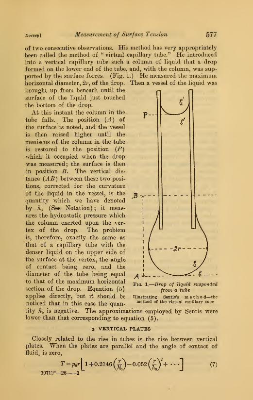
into a vertical capillary tube such a column of liquid that a drop
formed on the lower end of the tube, and, with the column, was sup-
ported by the surface forces. (Fig. 1.) He measured the maximumhorizontal diameter, 2r, of the drop. Then a vessel of the liquid was
brought up from beneath until the
surface of the liquid just touched
the bottom of the drop.
At this instant the column in the
tube falls. The position (A) of
the surface is noted, and the vessel
is then raised higher until the
meniscus of the column in the tube
is restored to the position (P)
which it occupied when the drop
was measured; the surface is then
in position B. The vertical dis-
tance (AB) between these two posi-
tions, corrected for the curvature
of the liquid in the vessel, is the
quantity which we have denoted
by ^0 (See Notation) ; it meas-
ures the hydrostatic pressure which
the column exerted upon the ver-
tex of the drop. The problem
is, therefore, exactly the same as
that of a capillary tube with the
denser liquid on the upper side of
the surface at the vertex, the angle
of contact being zero, and the
diameter of the tube being equal
to that of the maximum horizontal
section of the drop. Equation (5)
applies directly, but it should be
noticed that in this case the quan-
3
Fig. 1.
—
Drop of liquid suspended
from a tube
Illustrating Sentis's m e t h o d—the
method of the virtual capillary tube
tity Aq is negative. The approximations employed by Sentis werelower than that corresponding to equation (5).
3. VERTICAL PLATES
Closely related to the rise in tubes is the rise between vertical
plates. When the plates are parallel and the angle of contact of
fluid-L is zero,
r=p„.[l +0.2146(0-0.052(0+ . .
.] (7)
10712°—26 3
578 Scientific Papers of the Bureau of Standards \yoj. ti
(Volkmann (81)) where the distance between the plates is 2r, the
other quantities having the same meaning as before. If the plates
are inclined to one another at the angle <^, the line of contact of the
plates with one another being vertical, and if the axes of coordinates
coincide, respectively, with the line of contact of the plates and with
the intersection of the flat surface of the liquid in the reservoir with
the plane bisecting the angle between the plates, then to a first
approximation the equation of the median section of the meniscus is
T cos ^1
(Pi - P2) g tan2
This is the equation of an hyperbola. In order to facilitate the use
of this method, Grunmach (26) engraved on one of the plates a
series of hyperbolas, for each of which the value of the product xy
was known. Then, to make a measurement, the angle between the
plates is changed by means of a micrometer screw until the liquid
surface coincides with one of the hyperbolas, the plates being so
placed as to make this possible. The hyperbola determines the value
of xy, the reading of the micrometer fixes the value of </>, hence
if the value of ^1, the angle of contact of the lower fluid (fluidi) is
known, T can be found at once.
Quite recently Ferguson and Vogel (23a) have suggested a pro-
cedure for determining the surface tension from the positions of the
points of the hyperbola with reference to any set of axes which are
parallel to those of the hyperbola. This eliminates the difficulty of
determining the exact position of the latter axes.
4. PLATE AND CYLINDER
Wagstaff (88) used a plate pressed against the inside of a cylinder.
The coordinates of a series of points upon the projection of the menis-
cus upon the plate were measured, and from these and the radius of
the cylinder the value of T was calculated. The main advantages
claimed for this method over the use of capillary tubes is the facility
with which the apparatus can be cleaned and the fact that no very
small distances have to be measured. The volume of liquid required
is large.
Obviously in all these cases the surface in the reservoir must be
plane or due allowance must be made for its curvature. In the case
of plates, it is also necessary that observations be confined to those
portions that are so far from the edges that the shape of the meniscus
is the same as if the plates were of infinite extent. For these reasons
13lates are not so suitable as tubes.
In the use of the capillary rise methods for determining the tensions
of liquid-liquid surfaces it is necessary that care be taken to super-
Dorsei/] Measurement of Surface Tension 579
pose the liquids in such a way as to facilitate the drainage of the
film that is trapped between the wall and the advancing liquid. Onaccount of difficulties that may be produced by such trapping, it is
frequently impossible to test satisfactorily the freedom of motionof the surface over the wall.
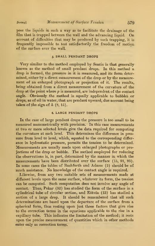
5. SMALL PENDANT DROPS
Very similar to the method employed by Sentis is that generally
knoAvn as the method of small pendant drops. In this method a
drop is formed, the pressure in it is measured, and its form deter-
mined, either by a direct measurement of the drop or by the measure-
ment of an enlarged photograph or projection of it. The results,
being obtained from a direct measurement of the curvature of the
drop at the point where p is measured, are independent of the contact
angle. Obviously the method is equally applicable to bubbles or
drops, as of oil in water, that are pendant upward, due account being
taken of the sign of h (8, 15).
6. LARGE PENDANT DROPS
In the case of large pendant drops the pressure is too small to be
measured manometrically with precision. In this case measurements
at two or more selected levels give the data required for computing
the curvature at each level. This determines the difference in pres-
sure from level to level, which, equated to the corresponding differ-
ence in hydrostatic pressure, permits the tension to be determined.
Measurements are usually made upon enlarged photographs or pro-
jections of the drop or bubble. The method employed for reducing
the observations is, in part, determined by the manner in which the
measurements have been distributed over the surface (15, 91, 93).
In some cases the tables of Bashforth and Adams (5) should be of
much assistance. No knowledge of the contact angle is required.
Likewise, from any two suitable sets of measurements made at
different levels upon the same surface, whatever its form, the tension
can be computed. Such computation does not involve any angle of
contact. Thus, Pekar (52) has studied the form of the surface in a
cylindrical tube of circular section, and Eotvos (13) has studied a
section of a large drop. It should be remembered that all such
determinations are based upon the departure of the surface from a
spherical form, thus resting upon just those factors that give rise
to the correction terms in the equations applicable to the rise in a
capillary tube. This indicates the limitation of the method ; it rests
upon the precise measurement of quantities which in other methods
enter only as correction terras.
580 Scientific Papers of the Bureau of Standards Woi. tt
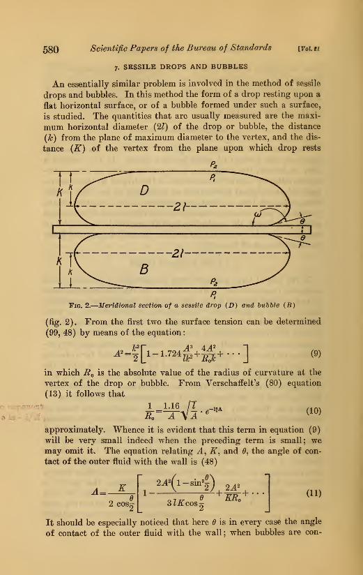
7. SESSILE DROPS AND BUBBLES
An essentially similar problem is involved in the method of sessile
drops and bubbles. In this method the form of a drop resting upon a
flat horizontal surface, or of a bubble formed under such a surface,
is studied. The quantities that are usually measured are the maxi-
mum horizontal diameter (2Z) of the drop or bubble, the distance
{h) from the plane of maximum diameter to the vertex, and the dis-
tance {K) of the vertex from the plane upon which drop rests
P.
D'21-
-21
B
p.
Fig. 2.
—
Meridional section of a sessile drop (D) and hnhble (B)
(fig. 2). From the first two the surface tension can be determined
(99, 48) by means of the equation
:
A' =^\ 1[ ''"§*'S* ](9)
in which ^0 is the absolute value of the radius of curvature at the
vertex of the drop or bubble. From Verschaffelt's (80) equation
(13) it follows that
i_=M5 /IBn A \A
IZA (10)
approximately. Whence it is evident that this term in equation (9)
will be very small indeed when the preceding term is small; wemay omit it. The equation relating J., K, and 6, the angle of con-
tact of the outer fluid with the wall is (48)
A=2 cos^
2A
SlKcos-(11)
It should be especially noticed that here 6 is in every case the angle
of contact of the outer fluid with the wall; when bubbles are con-
Doi'seyi Measv/rement of Surface Tension 581
sidered, B is the angle of contact of the surrounding liquid with the
wall ; when drops are considered, 9 is, as before, the angle of contact
of the surrounding fluid with the wall. The angle of contact of the
liquid forming the drop is w, the supplement of B (see fig. 2).
By combining (9) and (11) the angle of contact can be determined.
Equations equivalent to (9) and (11) are attributed (48) to Poisson.
The approximation of neither of these equations will be satisfactory
unless A/I is small as compared with unity. In much of the work
that has been done by this method the drops or bubbles have been
entirely too small for the approximations used to be satisfactory;
in nearly all of the earlier work only the first term of each of these
equations was used, thus making matters far worse. Quincke (54)
determined experimentally, in both water and alcohol, the ratios of
k and of K corresponding to air bubbles of various diameters to the
corresponding quantities for bubbles 10 cm in diameter and at-
tempted to correct his values by means of them.
Siedentopf (69) used drops about 1 cm in diameter and measured
the maximum horizontal diameter and the curvature at the vertex,
using an ophthalmometer. His observations were reduced by graph-
ical methods.
Although the method of sessile drops is very convenient for' deter-
mining the surface tension of fused materials at the instant of solidi-
fication, Verschaffelt (80) is probably right in saying that " a really
practical importance can not be ascribed to them." Others who have
used and discussed the method are Heydweiller (32, 33, 33a), Lohn-
stein (43, 44), and Worthington (94). Heydweiller (33a) gives a
table which facilitates the reduction of observations.
8. JAEGER'S METHOD
When the column of liquid that rise& in a tube dipping vertically
into a liquid is slowly forced down by applied gas pressure, it is
observed that the pressure steadily increases to a well-marked maxi-
mum just before a bubble escapes from the end of the tube. Thevalue of this maximum depends upon the surface tension and the
density of the liquid and upon the configuration of the apparatus.
Jaeger (34, 35) first employed this phenomenon for measuring the
surface tension, and the method is generally called by his name.
He first employed it for the determination of the way in which the
tension varies with the temperature ; and as at that time the equation
relating the maximum pressure to the radius of the tube and to other
factors had not been developed, he attempted only relative measure-
ments. He used two tubes of different diameters and adjusted the
difference in the depths of their immersion until the maximum pres-
sure was the same for each. Until the line of contact reaches the end
of the tube, the condition is exactly the same as in the case of capil-
582 Scientific Papers of the Bureau of Standards [Vol.ti
lary rise; whence it is evident that, to a first approximation, the
pressure will be proportional to the surface tension multiplied by a
function of the radius of the tube. Hence, in the case of two tubes
immersed to different depths, the hydrostatic pressure corresponding
to the difference in immersion will likewise be proportional to the
tension multiplied by a function of the radii of the two tubes. Fur-
thermore, it is evident that the next degree of approximation will
depend upon the density of the liquid. Jaeger assumed that it wouldbe obtained by simply multiplying the first order approximation bya function of the density alone. Under the conditions of that workhe found that this assumption fitted his observations within the lim-
its of his experimental error, the density function being linear.
Actually, the exact expression is not so simple. He emphasized the
importance of the end of the tube being broken off perfectly smoothand flat and at right angles to the axis of the tube, and he commentson the advantage of using a broken, rather than a ground end.
The advantages of this method are: {a) The continual renewal of
the surface reduces the troubles arising from surface contamination,
(h) the temperature control is facilitated by having the surface sur-
rounded by a large volume of liquid, {c) the use of a light man-ometric liquid, or of an inclined manometer, facilitates the measure-
ment of the pressure, {d) the radius that is to be measured, in the case
of absolute measurements, lies exactly at the end of the tube. Whilethe use of a light manometric liquid is of advantage in the case of
relative measurements, either after the manner of Jaeger or in the
case of a single tube when provision is made for adjusting the depth
to exactly the same amount in every case, its advantage is rather
illusory in other cases, as the precision is limited by the accuracy
with which the depth of immersion can be determined.
Since this early work, the equation relating the tension to the
diameter of the tube, the maximum pressure, and the density of the
liquid has been deduced by methods of approximation to a precision
which is ample for experimental work. Unfortunately, several in-
correct equations have been deduced and used, as pointed out bySchrodinger (66), and later by Verschaffelt (79). Four incorrect
equations have been found in the literature (9, 24, IT, 10), viz:
^ 2
-^ 2
•^~ 2
I-ttI(9 3U) (12)
(13)
(14)
(15)
Dofsey] Measv/rement of Surface Tensiori 583
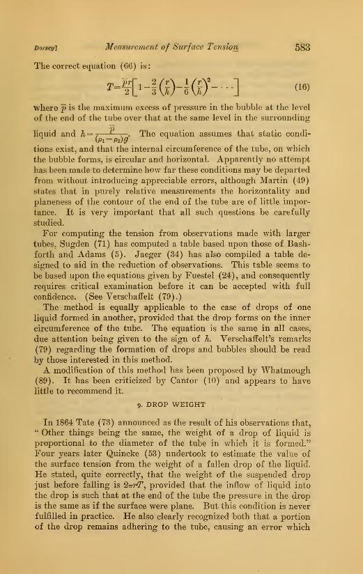
The correct equation (66) is:
^-l['-i(0-KO"--]where p is the maximum excess of pressure in the bubble at the level
of the end of the tube over that at the same level in the surrounding
liquid and h=-.—_ . . The equation assumes that static condi-
tions exist, and that the internal circumference of the tube, on which
the bubble forms, is circular and horizontal. Apparently no attempt
has been made to determine how far these conditions may be departed
from without introducing appreciable errors, although Martin (49)
states that in purely relative measurements the horizontality and
planeness of the contour of the end of the tube are of little impor-
tance. It is very important that all such questions be carefully
studied.
For computing the tension from observations made with larger
tubes, Sugden (71) has computed a table based upon those of Bash-
forth and Adams (5). Jaeger (34) has also compiled a table de-
signed to aid in the reduction of observations. This table seems to
be based upon the equations given by Fuestel (24), and consequently
requires critical examination before it can be accepted with full
confidence. (See Verschaffelt (79).)
The method is equally applicable to the case of drops of one
liquid formed in another, provided that the drop forms on the inner
circumference of the tube. The equation is the same in all cases,
due attention being given to the sign of h. Verschaffelt's remarks
(79) regarding the formation of drops and bubbles should be read
by those interested in this method.
A modification of this method has been proposed by "VYhatmough
(89). It has been criticized by Cantor (10) and appears to have
little to recommend it.
9. DROP WEIGHT
In 1864 Tate (73) announced as the result of his observations that," Other things being the same, the weight of a drop of liquid is
proportional to the diameter of the tube in which it is formed."
Four years later Quincke (53) undertook to estimate the value of
the surface tension from the weight of a fallen drop of the liquid.
He stated, quite correctly, that the weight of the suspended dropjust before falling is 27rr(r, provided that the inflow of liquid into
the drop is such that at the end of the tube the pressure in the dropis the same as if the surface were plane. But this condition is never
fulfilled in practice. He also clearly recognized both that a portion
of the drop remains adhering to the tube, causing an error which
584 Scientiftc Papers of the Bureau of Standards {Voi. 21
he thought would be negligible when the radius of the tube is very
small, and that the conditions attending the breaking away of the
drop are very complex; consequently, that the assumption that the
weight of the fallen drop is equal to 2TrrT can at best lead only to
approximate values of the tension, and that the method should be
used only when others are either not applicable or involve excessive
experimental difficulties. Unfortunately, his followers have quite
generally failed to recognize the limitations he pointed out and have
endeavored to elevate to the dignity of an exact law the approximate
numerical relation which he employed.
Worthington (91) in 1881 pointed out that the relation generally
assumedW=z2^rT (17)
could not be correct in any case, and that, in general, the relation
between the weight (W) and the surface tension (T) would not be
one of simple proportionality. Several writers have commented onthe fact that the weight must depend upon how rapidly the drops
form and must be sensitive to slight disturbances occurring at the
instant in which instability is setting in; and Vaillant (76)
Abonnenc (2), and Guye and Perrot (28b) have endeavored to
determine experimentally the relation between the weight of the
drop and the rate at which it forms. Even though the speed of
formation were excessively slow, the effect of disturbances wouldpersist, and, although the average of a number of drops formedunder the same nominal conditions might under certain conditions
exhibit a high degree of reproducibility, this would be no proof that
the average is the same as would be obtained under other conditions,
nor, in particular, would it be a proof that the average is the sameas would be obtained in the absence of all extraneous mechanical
jars, vibrations, or other disturbance.
Rayleigh (61), Kohlrausch (39), Harkins and Humphrey (31),
and Harkins and Brown (1(M) have studied experimentally the
variation of the ratio W/{2'7rrT) with the value of r/A; and Lohn-stein (45) has computed the same relation on the assumption that
the residue of the drop left pendant to the tube was the stable drop
for which the surface at the line of contact with the tube had the
same inclination to the vertical as that of the unstable one which fell.
The various tables thus prepared exhibit marked differences, due
doubtless to the effect of slight mechanical and other disturbances
upon the drop while passing through its condition of unstable equi-
librium. These differences emphasize the weakness of the methodas a means for obtaining reliable measurements of surface tension.
The tables are, nevertheless, in agreement in showing that the ratio
'W/{2TrrT) varies markedly with the value of r/A and passes through
a minimum when r/A is about equal to ^2
Dorsey] Measwrement of Surface Tension 585
Although these conclusions appear not to be accepted by Morgan
(50), Lohnstein (47) has pointed out that his observations are actu-
ally concordant with them. In the progress of his work Morgan has
been forced to limit the size of the tips he uses to those having radii
that differ but little from A -^2 for the liquids used for standardiza-
tion; their use for liquids for which this relation is not approxi-
mately fulfilled is unjustified. He evades the point by demandingthat the drop shall have a certain singular shape, described as bag-
like. This limitation is closely equivalent to the former ; but it is a
criterion that can not be applied with rigor and leaves the observer
uncertain whether the proper conditions have been satisfactorily met.
The numerical relation leaves no such uncertainty ; but in every case,
whatever be the criterion, there remains the uncertainty arising fromthe effects of slight disturbances occurring while the droj^ is in its
critical condition just preceding its fall.
The technique of this method, generally called the " drop-weight
"
method, is as simple as anyone could wish. For rapid work andwithin the limits of its reliability it would be the method of choice,
especially when only small amounts of liquid are available, but it is
not, and probably can not be made suitable for use where really accu-
rate determinations are required. The reproducibility characteristic
of averages is likely to lead to a very false estimate of the accuracy
that has been attained. For example, Eayleigh (61) says:
Successive collections, made without disturbance, gave indeed closely accord-
ant weights (often to one-thousandth part), but repetitions after cleaning andremounting indicated discrepancies amounting to one-half per cent, or even to
1 per cent.
Although the method is not promising for accurate determinations,
it is to be hoped that in Ferguson's proposed comparison of methods
it will be compared with others under all the stringent requirements
characteristic of precise physical work, so that its advantages as well
as its disadvantages may be brought to light and that the conditions
under which and the limits within which it can be trusted may be
finally established.
Papers treating of this method and published prior to 1917 havebeen critically reviewed by Guye and Perrot (28a) and by Perr6t
(52a). Appended to their reviews are extensive bibliographies. Inaddition to the articles already referred to, the following should be
consulted by those interested in this method: Davies (11), Ferguson
(19), Guthrie (27, 28), Harkins and Brown (30), Lohnstein (46).
The methods so far considered have been based upon the measure-
ment of the pressure exerted by a curved liquid surface. Obvi-
ously, it is possible to compute the tension from a direct measure-
ment of the pull exerted by the surface under certain conditions.
This is the basis of the numerous balance methods that have beenproposed and used.
586 Scientific Papers of the Bureau of Standards {Voi. ti
10. PULL OF VERTICAL FILM
Hall (29), Fahrenwald (14), Foley (24a), and Lenard, v. Dallwitz-
Wegener, and Zachmann (42a) measured the pull exerted by the
film formed upon a vertical rectangular frame when its uppermost
side was raised above the flat surface of the liquid in the reservoir.
The tension may be computed either from the maximum pull exerted
by the film as the frame is raised or from the pull of the film
after it has drained. Hall used both methods; the corrections to be
applied are uncertain and troublesome.
II. PULL ON VERTICAL PLATE
Wilhelmy (90) weighed the pull upon a vertical plate dipping into
the liquid. If the plate is very thin in comparison to its horizontal
length, the pull is approximately equal to Tcosd^ times the horizontal
perimeter of the plate. Correction must be made for the effect of
the liquid displaced by the submergence of the plate below the gen-
eral level of the liquid. If the lower edge lies above the general
level, there is likewise a correction for the liquid raised by adhesion
to the bottom of the plate. Hall eliminated these hydrostatic cor-
rections by making the weighing while the lower edge of the plate lay
in the level of the undisturbed surface.
Worthington (92) rolled the strip into a cylindrical spiral, thus
increasing the pull. He called this modification a "capillary
multiplier."12. PULL ON RING
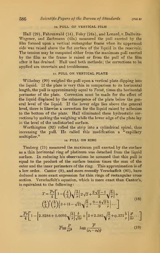
Timberg (75) measured the maximum pull exerted by the surface
as a thin horizontal ring of platinum was detached from the liquid
surface. In reducing his observations he assumed that this pull is
equal to the product of the surface tension times the sum of the
outer and the inner perimeters of the ring. This approximation is of
a low order. Cantor (9), and more recently Verschaffelt (80), have
deduced a more exact expression for thin rings of rectangular cross
section. Verschaffelt's equation, which is more exact than Cantor's,
is equivalent to the following
:
(18)
Pr4 [l-J2.8284 +
0.6095y|}-i= + [3+2.585^| + 0.371^^j|!...]
T=^ 7t= ,^
,(19)
Dorsoy] Measurement of Surface Tension 587
where P is the maximiiin pull, r is the mean radius of the ring, 28
is the thickness of the rin<^, p^—pz is the amount the density of
the liquid exceeds that of the overlying fluid.- By the use of an indi-
cating instrument, such as a torsion balance, for the measurement
of the maximum pull, the value of the surface tension can be very
quickly determined. The method has been used for the study of
the progressive changes which occur in the surface tension of col-
loidal and certain other solutions (50a). It should be noticed
that the equation (18) is derived on the assumption that the shortest
distance between the ring and the wall of the vessel containing the
liquid is so great that at a point midway between the two the sur-
face is truly flat. If the vessel is cylindrical, the surface will not
be flat unless this minimum distance amounts to some 2 or 3 cm,
depending upon the surface tension and the density of the liquid.
If the vessel is so small that the liquid surface between the ring and
the wall is nowhere flat, then, in order to obtain the value of the
surface tension, a correction will have to be applied to the quantity
T computed in accordance with equation (18). It is believed that
the mathematical expression for this correction has not been de-
rived, but it appears evident that the amount of the correction will
depend upon the properties of the liquid under study. When the
vessel is small, it is not generally allowable to assume that the sur-
face tension is proportional to the maximum pull, although such
proportionality may practically exist for small variations in the
tension. In much of the work done by this method the vessel has
been too small.
The theory of various detachment methods has been discussed byTichanowsky (T4a, 74b), and a recent paper by Lenard, v. Dallwitz-
Wegener, and Zachmann (42a) should be read by those expecting
to use such methods.
13. ADHESION PLATE
In the method known as that of the adhesion plate, the force re-
quired to lift a horizontal circular plate from the surface of the
liquid is measured. Two modifications of the method have been used.
In one the maximum pull exerted as the disk is raised is measured.
Ferguson's expression (16), slightly modified in form, for this
- Since this paper was written there has appeared an important paper (31a) by Har-kins, Young, and Cheng treating of the maxinrum pull upon a circular ring of circular
cross section. They have determined experimentally the value of the factor F in the
equation T=PF/4 TriJ for various values of A/R and of r/R, R and r being, respectively,
the i-adius of the ring and of its cross section. They denote by V the total volume of
liquid (P/ptg) lifted by the tension and give four curves, each showing the variation of
F with R^/V for a different fixed value of r/R. Their F corresponds formally to the ex-
pressions in the square brackets in equations (18) and (19) but is not comparable withthem because they are derived on the assumption tha.t the axial width, of the ring is
effectively infinite.
588 Scientific Papers of the Bureau of Staruiards [voi. tt
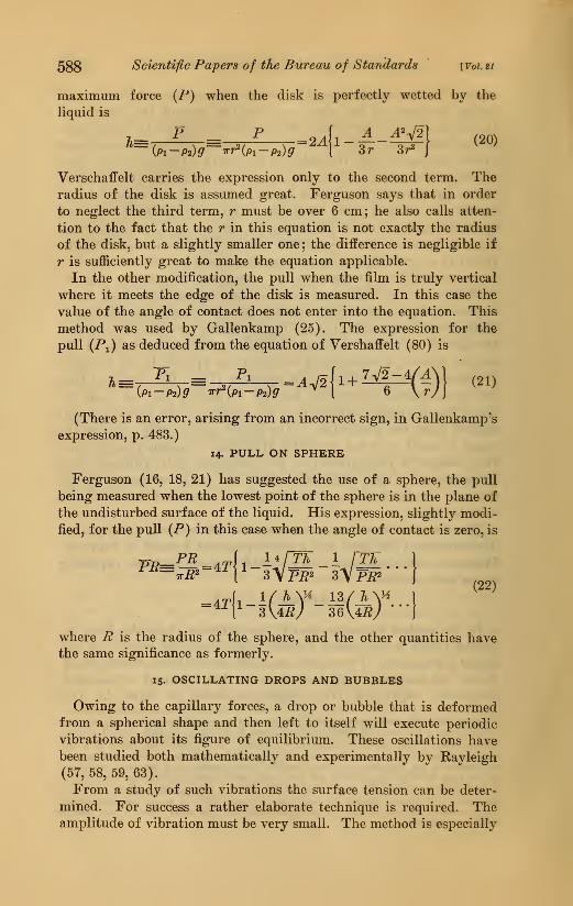
maximum force {P) when the disk is perfectly wetted by the
liquid is
Verschaffelt carries the expression only to the second term. Theradius of the disk is assumed great. Ferguson says that in order
to neglect the third term, r must be over 6 cm; he also calls atten-
tion to the fact that the r in this equation is not exactly the radius
of the disk, but a slightly smaller one ; the difference is negligible if
r is sufficiently great to make the equation applicable.
In the other modification, the pull when the film is truly vertical
where it meets the edge of the disk is measured. In this case the
value of the angle of contact does not enter into the equation. This
method was used by Gallenkamp (25), The expression for the
pull (Pi) as deduced from the equation of Vershaffelt (80) is
1--E. L=.v.[..i4-(^)) ,.,iPi-P2)g 7rr2(P:
(There is an error, arising from an incorrect sign, in Gallenkamp's
expression, p. 483.)
14. PULL ON SPHERE
Ferguson (16, 18, 21) has suggested the use of a sphere, the pull
being measured when the lowest point of the sphere is in the plane of
the undisturbed surface of the liquid. His expression, slightly modi-
fied, for the pull (P) in this case when the angle of contact is zero, is
=4r|i-irAf_i3/A\(22)
where B is the radius of the sphere, and the other quantities havethe same significance as formerly.
15. OSCILLATING DROPS AND BUBBLES
Owing to the capillary forces, a drop or bubble that is deformedfrom a spherical shape and then left to itself will execute periodic
vibrations about its figure of equilibrium. These oscillations havebeen studied both mathematically and experimentally by Rayleigh
(57,58,59,63).
From a study of such vibrations the surface tension can be deter-
mined. For success a rather elaborate technique is required. Theamplitude of vibration must be very small. The method is especially
Dorsey] Measitremeni of Surface Tension 589
valuable, in that it permits the tension to be observed within a very
short interval after the surface is formed. Lenard (42) employedthe method as applied to freely falling oscillating drops. He foundthat the tension decreased as the age of the drop increased; this heattributed, probably correctly, to the contamination of the surface.
Recently Kutter (40) devised a very simple, but probably not very
precise, method for determining the period of the drops. He madeuse of the phenomenon described by Thomson and Newall (74) in
1885. When drops of one liquid fall into another with which it
mixes, they form vortex rings that travel a greater or lesser distance
into the second liquid. The depth to which they penetrate depends
upon the form of the drop at the instant of impact ; as the distance
the drops fall before striking the liquid surface is progressively in-
creased the depths reached pass through a succession of maximaand minima. The distance from one maximum to the next is equal
to the distance that the drop falls while it is executing one complete
vibration. His observations indicate that he can determine this dis-
tance with considerable precision ; but it would appear to be necessary
for the vibrations to have quite an appreciable amplitude, as com-
pared with the radius of the drop, if the phenomenon is to be sharply
defined, and the mathematical relation connecting the period with
the surface tension and other quantities assumes that the amplitude
is small in comparison with the radius. For this reason confidence
can not be placed in the results, although those displayed appear
to lead to nearly the correct values.
i6. VIBRATING JETS
If at any point fixed with reference to its source a jet of liquid is
subjected to a periodic change in form, it will be thrown into oscilla-
tions, which will exhibit themselves as stationary waves in the jet.
Such vibrations have been studied both mathematically and experi-
mentally by Rayleigh. His observations (57, 58) did not yield very
satisfactory values for the tension. The subject was taken up again
by Pedersen (51) with a very greatly improved technique. Heshowed that the method was capable of a precision that is comparablewith those of other methods. The following year it was employedby Bohr (6). He elaborated Rayleigh's mathematical treatment anddeveloped expressions that take account of the amplitude of the
vibrations and of the damping of the waves. He obtained for the
tension a value somewhat lower than that found by Pedersen andmore nearly in agreement with the best of those found by other
methods. He thinks that Pedersen's values are too high because heworked too near the orifice, obtaining measurements before thevibration had settled down to its normal condition.
590 Scientific Papers of the Bureau of Standards [Voi. et
17. RIPPLES
The velocity with which waves travel over the surface of a liquid
depends upon the surface tension as well as upon the acceleration of
gravity. The relative importance of these two factors depends uponthe length of the wave. When the wave length is so short that the
surface tension is the more important, the waves are commonlycalled ripples. Under suitable conditions the surface tension can be
determined from the wave length and the period of ripples. This is
known as the ripple method. The effect of the surface tension upon
the velocity of surface waves was investigated by Kelvin in 1871
(37). The ripple method was used first by Eayleigh (60) in 1890
in his study of the contamination of water surfaces. (See also
Lamb (41), Tait (72), Rayleigh (63).)
If the amplitude of the waves is so small that the square of the
slope of the surface is at every point negligible in comparison with
unity, if the waves are plane, and if the depth of the liquid is great
in comparison with the length of the waves, then Kelvin's equation
(23) is applicable
,^(Pi
27rr2^''''^
X Alt'
7^= (PI +PP! coth^^ - iBi:zpl9]^ (23)
where A, Is the wave length, t is the period, g the acceleration of
gravity, T the surface tension, and I is the depth of the liquid;
Pi is the density of the lower liquid. Since T varies as the cube of
the wave length and inversely as the square of the period, these
quantities must be measured with extreme accuracy. This, however,
can be done without great difficulty. The method obviously requires
a large surface of liquid in order (a) that the waves reflected fromthe walls shall die out before reaching the portion under observation,
and (h) that the undisturbed surface shall be truly plane. This
large surface invites contamination, but has the advantage of dis-
tributing any small amount of contamination over a large surface,
thus reducing its effect. In addition, it permits of a mechanical
cleaning of the surface, thus enabling the observer to speak with
confidence regarding the possible effect of the contamination that
exists. The last is very desirable. The method is thoroughly trust-
worthy, but measurements must not be made too near the source,
because, owing to the small amplitude of the waves, a very slight
curvature of the surface will cause an appreciable relative displace-
ment of the crests.
The necessity for considering this source of error, which has been
quite generally ignored, was pointed out by the author a number of
years ago. In that work (12) it was found that the curvature as far
as 3 cm from the plate used for generating the waves was sufficient
Dorsey] Measurement of Surface Tension 59
1
to displace the apparent crests by an appreciable amount. Conse-
quently, no measurement should be made closer to the generator
than 3.5 or 4 cm. Several experimenters have, however, employed
observations made within a few millimeters of the generator. Someinvestigators, instead of using plane waves, have used the interfer-
ence pattern produced by two sets of circular waves, assuming that
the effects of the two sets of waves are directly additive; it is not
evident that this is permissible, as here we have to do with a surface
curvature, not with a mere surface elevation. (For experimental
details and data see Kayleigh (60), Dorsey (12), Kaliihne (36),
Bohr (6), Grunmach (101, 102).)
Of the methods that have been considered a knowledge of the
angle of contact is not required in {a) Sentis's method of virtual
capillary tube, (b) pressure in a pendent drop, (c) measurement
of the form of the surface so as to get the curvature at two different
levels (this includes the method of Anderson and Bowen), [d) ses-
sile drops or bubbles when the maximum horizontal diameter and
either the distance from the vertex to the plane of the maximumdiameter or the curvature at the vertex are used, {e) Jaeger's method,
(/) pull of a true film, {g) maximum pull upon a thin ring, {h)
pull on an adhesion plate when the surface is vertical at the line of
contact, (^) oscillation of drops, {j) vibration of jets, and {k)
ripples.
Those that require a knowledge of the angle of contact are {a) all
others involving capillary rise in tubes, between plates, or against
solid walls, {h) sessile drops or bubbles when the total thickness is
used, {c) pull upon a vertical plate (Wilhelmy's method),{d) maxi-
mum pull upon an adhesion plate, and {e) pull upon a sphere.
The drop-weight method stands by itself as one involving undeter-
mined factors.
Before closing, reference should be made to a few other articles.
Those interested in capillary phenomena themselves will wish to read
the article on " capillarity " in the Encyclopedia Britannica, andalong with that Kelvin's comments (105) should be read. Boys's
article (97) on the drawing of curves by their curvature, Pockels's
article (107) on capillarity, and Maxwell's chapter on capillarity
(106) should also be read. These and a few others that have not
been referred to in the preceding portions of this article have been
placed in a supplementary list at the end of the bibliography. Theentries which are unnumbered have not been recently verified; they
are believed to be correct.
592 Scientific Papers of the Bureau of Standards {Yql u
IV. BIBLIOGRAPHY
1. Ablett, K, Phil. Mag. (6), 46, pp? 244-256; 1923. Contact angle.
2. Abonnenc, L., Comp. Rend., 168, pp. 556-557; 1919. Fallen drops.
3. Anderson, A., and Bowen, J. E., Phil. Mag. (6), 31, pp. 143-148; 1916.
Capillary tube and curvature.
4. Anderson, A., and Bowen, J. E., Phil. Mag. (6), 31, pp. 285-289; 1916.
Contact angle.
5. Bashforth and Adams; An attempt to test the theory of capillary action.
Cambr. "Univ. Press ; 1888. Shape of drops ; numerical tables computed.
5a. Bigelow, S. L., and Hunter, F. W., J. Physical Chem., 15, pp. 867-380;
1911. Capillary height by means of perforated plate.
6. Bohr, N., Phil. Trans. (A), 309, pp. 281-317; 1909. Jet vibration.
7. Bosanquet, C. H., and Hartley, H., Phil. Mag. (6), 42, pp. 456-462; 1921.
Contact angle, measurement of.
8. Boys, v., Soc. Chem Ind. J., 39, pp. 58-60; 1920. Measurement of small
drop ; interfacial tension.
9. Cantor, M., Wied. Ann., 47, pp. 399-423 ; 1892. Detaching of ring ; Jaeger's
method.
10. Cantor, M., Ann. Physik (4), 7, pp. 698-700; 1902. Jaeger's method.
10a. Carver, E. K., and Hovorka, F., J. Am. Chem. Soc, 47, pp. 1325-1328;
1925. Capillary height by means of perforated plate.
11. Davies, A. C. H., Am. Chem. Soc. J., 40, pp. 784-785; 1918. Tips for drop-
weight method.
12. Dorsey, N. E., Phil. Mag. (5), 44, pp. 369-396; 1897; also Phys. Rev.,,
5, 170-181, 213-230; 1897. Ripples.
13. Eotvos; Wied. Ann., 27, pp. 448-459; 1886. Curvature measured optically.
14. Fahrenwald, A. W., Opt. Soc. Am. J., 6, pp. 722-733; 1922. Pull by fihn.
15. Ferguson, A., Phil. Mag. (6), 33, pp. 417-430; 1912. Photographic measure-
ment of pendant drops.
16. Ferguson, A., Phil. Mag. (6), 26, pp. 925-934; 1913. Force on sphere,
and on horizontal disk.
17. Ferguson, A., Phil. Mag. (6), 28, pp. 128-138; 1914. CapiUary tube.
18. Ferguson, A., Phil. Mag. (6), 28, pp. 149-153; 1914. Forces on sphere.
19. Ferguson, A., Phil. Mag. (6), 30, pp. 632-637; 1915. Drop weight.
20. Ferguson, A., and Dowson, P. E., Faraday Soc. Trans., 17, pp. 384-392;
1921-22 ; also Manchester Lit. Phil. Soc, Mem., 65, No. 5 ; 1921. Capil-
lary tube method.
21. Ferguson, A., Faraday Soc Trans., 17, pp. 370-383; 1921-22; also Manches-
ter Lit. Phil. Soc, Mem., 65, No. 4; 1921. Studies in capillarity.
22. Ferguson, A., Proc Phys. Soc (Lond.), 36, pp. 37-44; 1923. Capillary tube,
small volume of liquid.
23. Ferguson, A., Phil. Mag. (6), 47, pp. 91-94; 1924. Contact angle.
23a. Ferguson, A., and Vogel, I., Proc. Phys. Soc, 38, pp. 193-203 ; 1926. Thehyperbola method.
24. Feustel, R., Ann. Physik (4), 16, pp. 61-92; 1905. Jaeger's method.
24a. Foley, A. L., Physical Rev., 3, pp. 381-386 ; 1896. Pull on mica frame.
25. Galleukamp, W., Ann. Physik (4), 9, pp. 475-494; 1902. Adhesion plate.
26. Grunmach, L., Verb. Deut. physik. Ges., 12, pp. 847-859; 1910. Inclined
plates ; hyperbolas.
27. Guthrie, F., Proc Roy. Soc (A), 14, pp. 22-33; 1865. Bubbles.
28. Guthrie, F., Proc Roy. Soc (A), 13, pp. 444-483; 1864. Drops.
28a. Guye, Ph. A., and Perrot, F. L., Arch. Sci. Phys. et Nat, 11, pp. 225-345;
1901. Critical study of drop-weight method. Bibliography.
Dorset/] Measu/rement of Surface Tension 593
28b. Giiye, Ph. A., and Perrot, F. L., Arcli. Sci. Phys. et Nat., 15, pp. 132; 1003.
Experimental study of form and weight of drops, both static and
dynamic.
29. Hall, T. P., Phil. Mag. (5), 36, pp. 385-413; 1893. Weighing methods;
bibliography of various methods.
30. Harkins. W. D., and Brown, F. E., Am. Chem. Soc. J., 38, pp. 246-252 ; 1916.
Drop weight.
31. Harkins, W. D., and Humphery, F. C, AM. Chem. Soc. J., 38, pp. 228-246;
1916. Drop weight ; capillary tube. Three articles.
31a. Harkins, W. D., Young, T. F., and Cheng, L. H., Science, 64, pp. 333-336;
1926. Detaching of anchor ring. Experimental determination of ratio
of tension to maximum pull and its variation with the capillary constant
and the size of the ring,
32. Heydvveiller, A., Wied. Ann., 62, pp. 694-699; 1897. Sessile drops.
33. Heydweiller, A., Wied. Ann., 62, pp. 700-701; 1897. Sessile drops.
33a. Heydweiller, A., Wied. Ann., 65, pp. 311-319; 1898. Drops; table to
facilitate reduction of observation.
34. Jaeger, F. M., Zeits. Anorg. Chem., 101, pp. 1-214 ; 1917. Jaeger's method.
35. Jaeger, F. M., Sitzb. Akad. Wiss. Wien (2a), 100, pp. 245-270; 1891.
Jaeger's method.
35a. Johlin, J. M., Science, 64, pp. 93-94; 1926. Detaching of ring. Variation
of tension with age of surface.
36. Kalahne, A., Ann. Physik (4), 7, pp. 440-476; 1902. Ripples.
37. Kelvin, Phil. Mag. (4), 42, pp. 362-377; 1871. Ripples; mathematical.
38. Kiplinger, O. C, Am. Chem. Soc. J., 42, pp. 472-476; 1920. Inclined
capillary.
39. Kohlrausch, Fr., Ann. Physik (4), 22, pp. 191-194; 1907. Drop weight.
40. Kutter, V., Physik, Zeits., 17, pp. 424-429, 573-579; 1916. Oscillating
drops; vortex rings.
41. Lamb, H., Hydrodynamics, Chap. IX; Cambridge Univ. Press.
42. Lenard, P., Wied. Ann., 30, pp. 209-243; 1887. Oscillating drops.
42a. Lenard, P., v. Dallwitz-Wegener, R., and Zachmann, E., Ann. der Physik,
74, pp. 381-404; 1924. Detachment methods. Frame and ring.
43. Lohnstein, Th., Wied. Ann., 53, pp. 1062-1073 ; 1894. Sessile drops.
44. Lohnstein, Th., Wied. Ann., 54, pp. 713-723; 1895. Sessile drops.
45. Lohnstein, Th., Ann. Physik (4), 22, pp. 767-781; 1907. Drop weight.
46. Lohnstein, Th., Zeits. physik, Chem., 64. pp. 686-692; 1908. Drop weight.
47. Lohnstein, Th., Zeits. physik, Chem., 84, pp. 410-418; 1913. Drop weight.
48. Magie, W. F., Phil. Mag. (5), 26, pp. 162-183; 1888. Contact angle; sessile
drops.
49. Martin, E., Sitzb. Akad. Wiss. Wien (2a), 123, pp. 2491-2507; 1914.
Jaeger's method.
50. Morgan, J. L. R., Am. Chem. Soc, J., 37, pp. 1461-1467; 1915. Dropweight. Numerous other papers by same author and collaborators in
this journal.
50a. du Noiiy, P. L., Science, 59, pp. 580-582 ; 1924. Surface tension of solu-
tions of colloids.
50b. du Noiiy, P. L., J. de Physique (6), 6, pp. 145-153; 1925. Surface tension
of colloids by ring method.
51. Pedersen, P. O., Phil. Trans. (A), 207, pp. 341-392; 1908. Jet vibration.
52. Pekar, D., Zeits. physik. Chem., 39, pp. 433-452; 1902. Optical method.
52a. Perrot, F. L., J. chim. phys., 15, pp. 164-207; 1917. Drop-weight method.
Review of work since 1900. Bibliography.
53. Quincke, G., Pogg. Ann., 135, pp. 621-646; 1868. Drop weight.
594 Scientific Papers of the Bureau of Standards ivoi. ti
54. Quincke, G., Pogg. Ann., 160, pp. 337-374; 1877. Sessile drops.
55. Quincl^e, G., Wied. Ann., 2, pp. 145-194 ; 1877. Contact angle.
56. Quincke, G., Wied. Ann., 52, pp. 1-22; 1894. Contact angle.
57. Rayleigh, Proc. Roy. Soc. (A), 29, pp. 71-97; 1879. Jet vibration.
58. Rayleigb, Proc. Roy Soc. (A), 34, pp. 130-145; 1882. Jet vibration.
59. Rayleigh, Proc. Roy. Soc. (A), 47, pp. 281-287; 1890. Jet vibration.
60. Rayleigh, Phil. Mag. (5), 30. pp. 386-400; 1890. Ripples; contamination.
61. Rayleigh, Phil. Mag. (5), 48, pp. 321-337; 1899. Drop weight; jets; con-
tamination.
62. Rayleigh, Proc. Roy. Soc. (A), 92, pp. 184r-195; 1916. Capillary tube,
mathematical.
63. Rayleigh, Theory of sound, 2, pp. 351-375. Macmillan & Co. ; 1896.
64. Richards, T. W., and Carver, E. K., Am. Chem. Soc. J., 43, pp. 827-S47;
1921. Contact angle ; curvature of surface ; capillary rise.
65. Schmidt, Th., Wied. Ann., 16, pp. 633-660; 1882 Surface viscosity.
66. Schrodinger, E., Ann. Physik (4), 46, pp. 413-418; 1915. Jaeger's method,
mathematical.
67. Sentis, H., Journ. de Phys. (2), 6, pp. 571-573; 1887. Virtual capillary.
68. Sentis, H., Journ. de Phys. (3), 6, pp. 183-187; 1897; also Annales, Univ.
Grenoble. Virtual capillary; contact angle.
69. Siedentopf, H., Wied. Ann., 61, pp. 235-266 ; 1897. Sessile drops.
70. Sugden, S., J. Chem. Soc. (Lond.), 119, pp. 1483-1492; 1921. Capillary
tubes.
71. Sugden, S., J. Chem. Soc. (Lond.), 121, pp. 858-866; 1922. Jaeger's
method.
72. Tait, P. G., Proc. Roy. Soc. Edinb., 17, pp. 110-115; 1890. Ripples.
73. Tate, T., Phil. Mag. (4), 27, pp. 176-180; 1864. Drop weight.
74. Thomson, J. J., and Newall, H. F., Proc. Roy. Soc. (Lond.), (A), 39, pp.
417-436; 1885. Vortex rings by falling drops.
74a. Tichanowsky, I. L, Physik Zeits., 25, pp. 299-302; 1924. Theory of
detaching ring. Correction for inclination.
74b. Tichanowsky, I. I., Physik Zeits., 26, pp. 522-525; 1925. Theory of
several detachment methods.
75. Timberg, G., Wied. Ann., 30, pp. 545-561; 1887. PuU on ring.
76. Vaillant, P., Compt. Rend., 160, pp. 596-598; 1915. Drop weight.
77. Verschaffelt, J., Comm. Leiden, No. 32 ; 1896. Coaxial tubes.
78. Verschaffelt, J., Comm. Leiden, Suppl. No. 42c ; 1918 ; also K. Akad. Amster-
dam, Proc, 21, pp. 357-865; 1919. Small drops and bubbles, mathe-
matical.
79. Verschaffelt, J., Comm. Leiden, Suppl. No. 42d ; 1918 ; also K. Akad. Amster-
dam, Proc, 21, pp. 366-374; 1919. Applications of small drops andbubbles.
80. Verschaffelt, J., Comm. Leiden, Suppl. No. 42e ; 1918 ; also K. Akad. Amster-
dam, Proc, 21, pp. 836-849; 1919. Large drops and bubbles; mathe-
matical and experimental.
81. Volkmann, P., Wied. Ann., 11, pp. 177-209; 1880. Capillary tubes; criti-
cally experimental.
82. Volkmann, P., Wied. Ann., 53, pp. 633-663; 1894. Capillary tubes; criti-
cally experimental.
83. Volkmann, P., Wied. Ann., 53, pp. 664-666; 1894. Remarks on preceding.
84. Volkmann, P., Wied. Ann., 56, pp. 457-491; 1895. Surface tension of
water.
85. Volkmann, P., Wied. Ann., 62, pp. 507-521 ; 1897. Remarks on papers of
1894 and 1895.
Doi-seyi Measurement of Surface Tension 595
8G. Volkmann, P., Wied. Ann., 06, pp. 194-20G; 1898. Capillary tubes, critically
experimental.
87. Volkmann, P., Wied. Ann., 28, pp. 135-144; 188G. Contact angle.
88. Wagstaff, J. E. P., Phil. Mag. (6), 45, pp. 88-94; 1923. Rise between plate
and cylinder.
89. Whatmough, W. H., Zeits. physik, Cbem., 39, pp. 129^193; 1902. Jaeger's
method, modified.
90. Wilbelmy, L., Pogg. Ann., 119, pp. 176-217; 1^63. Pull on vertical plate.
91. Worthington, A. M., Proc. Roy. Soc. (A), 32, pp. 362-377; 1881. Pendant
drops.
92. Worthington, A. M., Phil. Mag. (5), 19, pp. 43^6; 1885. Capillary
multiplier.
93. Worthington, A. M., Phil. Mag. (5), 19, pp. 46-48; 1885 Pendant drops.
94. Worthington, A. M., Phil. ]\Iag. (5), 20, pp. 51-66; 1885. Sessile drops.
SUPPLEMENTAL BIBLIOGRAPHY
95. Devaux, H., Journ. de Phys. et Rad. (6), 4, pp. 293-309; 1923. Wetting of
surfaces.
96. Devaux, H., Bull. soc. fr. physique, p. 184S ; 1923. Wetting of surfaces.
97. Boys, v., Phil. Mag. (5), 36, pp. 75-82; 1893. Drawing curves.
98. Ferguson, A., Phil. Mag. (6), 24, pp. 837-844; 1912. Large capillary sur-
face, mathematical treatment.
99. Ferguson, A., Phil. Mag. (6), 25, pp. 507-520; 1913. Large drops; mathe-
matical treatment.
100. Ferguson, A., Phil. Mag. (6), 28, pp. 403-412; 1914. Jaeger's method;
effect of overlying gas.
101. Grunmach, L., Ann. Physik. (4), 9, pp. 1261-1285; 1902. Ripples.
102. Grunmach, L., Wlss. Abb. K. Norm. Eichungs-Komm, Heft, 7, pp. 45-129;
1908. Ripples.
103. Grunmach, L., and Bein, W., Wiss. Abh. K. Norm. Eichungs-Komm, Heft,
9, pp 1-18 ; 1917 ; also Zeits. Instk., 39, p. 195 ; 1919. Inclined plates.
104. Harkins, W. D., and Brown, F. E., Am. Cbem. Soc. J., 41, pp. 499-524;
1919. Drop weight ; table of corrections.
105. Kelvin, Popular lectures and addresses, 1, pp. 1-79.
106. Maxwell, J. C, Theory of heat, chap. 20.
107. Pockels, A., Winklemann : Handbuch der Physik (ed. 2), 1.
108. Quincke, G., Pogg. Ann. 105, pp. 1-48; 1858. Sessile drops; mercury.
109. Quincke, G., Pogg. Ann., 139, pp. 1-89; 1870. Sessile drops; interfacial
tension.
110. Quincke, G., Wied. Ann., 61, pp. 267-280; 1897. Critical discussion of
capillary measurements.
Clairaut, Theorie de la figure de la terre. Chap. X. ; 1743.
110. Gauss, Werke, 5, pp. 30-77. Principia generalia theoriae figurae fluidorum
in statu aequilibrii ; 1830.
Laplace, Theorie de Taction capillaire, Mec. celeste, L. X. Suppl. ; 1806.
Mathieu, Theorie de la capillarite ; 1883.
Poisson, Nouvelle theorie de Taction capillaire ; 1831.
Young, Th. Phil. Trans. (A), 1, p. 65; 1805.
Plateau, J., Statique exp^rimentale et theorique des liquides, Paris; 1873.
Washington, June 1,*1926.