An Introduction to
Design for Manufacture (DFM)
Instructor: Mike L. [email protected]
and our core manufacturing processes:
• Plastic Molding
• Rapid Prototyping/3D Printing
• Sheet Metal
• Bar & Tube Fabrication
• Metal Casting
• Machining
ME170
CAD

Understanding Manufacturing Cost of Consumer Products– predominantly Sheet metal and Injection Molded Plastic
Look at retail prices…divide by 3!

Design for Manufacture (DFM) Overview
Product Development teams need to know cost early in design to do what-if analysis and explore alternative designs before expensive hard tooling decisions finalized
aPriori’s integrated CAD/DFM software utilizes 3D CAD’s mathematical definition of the part/assembly to provide instant cost estimates as you create geometry.
Necessary today due to high overseas competition and overseas sourcing opotunities
Need to know early if cost targets are being met -redesign if necessary before its too late.

$95
$10
$25
$8
$75
$100
$55
$400
$0.30
$60,000
$1.20
$5,000
x3
Piece-part costs
Tooling costs
A simple fork end for Pneumatic Piston
Production Volume: Recurring Costs versus Non-Recurring Costs
Machine from Solid
Welded Assembly
Casting Stock Channel Sheet Metal Injection Mold
Design for Manufacture (DFM) Example

Design for Assembly (DFA)Fewer Parts generally means lower overall mfg.cost
Number of Parts: 24 8 4 2
Assembly Time (s): 100 38 10 3

• CAD-integrated feature recognition and extraction methodology to
provide engineers with accurate real-time cost feedback during design.
Geometric Cost
Drivers Physics Based
Mechanistic
Manufacturing
Process Models
(cycle times ->
cost)
Times and
CostsNon-Geometric
Cost Drivers
CAD Solid
Model
feature extraction
algorithms
1. Cost Scripting
Language
2. Parameterized machine,
material, tooling and
labor Database
Optimum manufacturing sequence
automatically derived from CAD Solid
Model based on deterministic routing
logic and Genetic Algorithmsreal-time cost feedback loop
Routing
Engine
User
Feature Based Costing (FBC) Research
In-House Supplier
Virtual Production Environments
• Industry/University Collaborative research project: Started in 1992 with
UIUC / John Deere Collaboration - now commercialized www. aPriori.com*
* Philpott, M.L., “Integrated Real-Time Feature Based Costing (FBC),” U.S. Patent No. 7,065,420, June 20, 2006
aPriori

Cost Statement - Calculated Results (one process, one part)
Direct Variable Costs:
Material Cost $1.22 = Part Weight * Raw Material Cost Per Kg / Material Utilization
Labor Cost $0.36 = Labor Time * Labor Rate
Direct Overhead $0.47 = Cycle Time * Labor Rate* Overhead Rate
Subtotal $6.00 = Material Cost + Labor Cost + Direct Overhead
Expendable Tooling $0.11 = Expendable Tooling Cost
Set-up costs $0.27 = Set-upTime * LaborRate / (AnnualVolume * NumberOfParts / BatchesPerYear)
Additional Direct Costs $0.00 = Additional Direct Costs (none)
Other Direct Costs $0.38 = Expendable Tooling + Set-up Costs + Additional Direct Costs
Piece Part Cost $6.38 = Material Cost + Labor Cost + Direct Overhead + Other Direct Costs
Direct Fixed Costs:
5,000
Direct Fixed Costs:
Hard Tooling $3.00 = CapitalTooling / (AmortizationVolume)
Fixtures and Jigs $0.00 = CapitalFixtures&Jigs / (AmortizationVolume)
Programming Cost $0.03 = ProgrammingTime * LaborRate / (AmortizationVolume)
Amortized Investment $3.03 = Hard Tooling + Fixture and Jigs + Programming Cost
Total Cost $9.42 = Piece Part Cost + Amortized Investment
Recommended Lowest Cost Process returned to user, if "Amortization Method" chosen
Total Cost used for
Comparison$9.42 = Total Cost, as above
Recommended Lowest Cost Process returned to user, if "Payback Method" chosen
Total Cost used for
Comparison$13.96
2,000
AmortizationVolume =
AnnualProductionVolume*NumberOfParts*ProductLife =
uses, AmortizationVolume =
AnnualVolume * NumberOfParts * PaybackPeriod =
Cost Accounting
Insights and Cost Reduction Opportunities

Plastic Molding Injection Molding: Standard IM, Structural Foam Molding,
Reaction Injection Molding (RIM)
KEY COST DRIVERS
• Wall Thickness (typical: 1- 2mm)
• Undercuts - side Actions in the mold
• Number of cavities in the mold

Structural Foam Molding Thick parts => ¼ inch (6mm)

Blow Molding and Rotational Molding
Blow moldingBottles and small disposable containers
Rotational moldinglarger hollow shapes.

1. Mold Closes 2. Inject Plastic
3. Cooling 4. Mold Opens
Injection Molding
Labor Cost = (Mold Close time + Injection Time + Cooling Time + Mold Open time) * $/hr rate

The Mold(Tooling)
Tooling Cost = Cost to design and build this mold tool
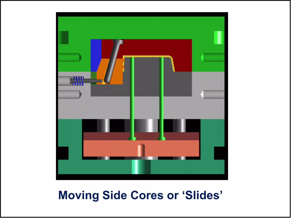
Moving Side Cores or ‘Slides’

Moving Internal Cores or ‘Lifters’

Avoiding Moving Side Cores and Lifters (1) – allow feature to deflect as part is ejected from the mold

Avoiding Moving Side Cores and Lifters (2) –provide relief hole for core

Polypropylene (1.5¢/cu. in): Outstanding
resistance to flex and stress cracking. Excellent chemical
resistance and electrical properties., Good impact
strength above 15ºF. Good thermal stability, light weight,
low cost. Some grades can be electroplated.
Polystyrene (1.7¢/cu. in): Low cost, easy to
process, rigid, crystal-clear, brittle. Low moisture
absorption, and heat resistance. Poor outdoor stability.
Polyethylene - HDPE & LDPE (1.2¢/cu. in)Lightweight, easy to process, low cost material. Poor dimensional stability and heat resistance. Excellent chemical resistance and electrical properties.
4
LDPE
2
HDPE
Common Thermoplastic Materials (1)
5
PP
6
PS

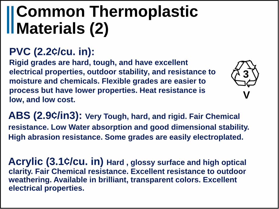
PVC (2.2¢/cu. in): Rigid grades are hard, tough, and have excellent
electrical properties, outdoor stability, and resistance to
moisture and chemicals. Flexible grades are easier to
process but have lower properties. Heat resistance is
low, and low cost.
ABS (2.9¢/in3): Very Tough, hard, and rigid. Fair Chemical
resistance. Low Water absorption and good dimensional stability.
High abrasion resistance. Some grades are easily electroplated.
Acrylic (3.1¢/cu. in) Hard , glossy surface and high optical clarity. Fair Chemical resistance. Excellent resistance to outdoor weathering. Available in brilliant, transparent colors. Excellent electrical properties.
Common Thermoplastic Materials (2)
3
V

PETE (4.9¢/cu. in)
Crystal clear and hard. Used widely for shampoo bottles. Good moisture, and chemical resistance. Good dimensional stability.
Acetal (5.8¢/cu. in)
Very Strong, stiff, and low tendency to stress crack. High resistance to chemicals. Retains most properties when immersed in hot water. Exceptional dimensional stability. High abrasion resistance. Low coefficient of Friction.
Polyurethane (6.1¢/cu. in)
Tough, extremely abrasion and impact-resistant. Good electrical properties and chemical resistance. UV exposure causes brittleness, lower properties, and yellowing.
PETE
1
Common Thermoplastic Materials (3)
Other
7

Fluoroplastics (30 - 65¢/cu. in): PTFE, FEP, PVDF etc. Family
of high cost, low-to-moderate strength. Excellent chemical resistance.
Low Friction. Outstanding stability at high temperatures.
Polycarbonate (6.3 ¢/cu. in): Highest impact resistance of any rigid, transparent plastic. Excellent outdoor stability and resistance to creep under load. Fair chemical resistance. Some aromatic solvents cause stress cracking.
Nylon (6/6-5.9 ¢/cu. in;6/12 - 9.0 ¢/cu. in;
+glass -16.3¢/cu. in): Family with outstanding
toughness and wear resistance. Low Coefficient of Friction.
Excellent chemical resistance and electrical properties.
Hygroscopic; dimensional stability is poor. Some grades are
electroplatable.
Common Thermoplastic Materials (4)

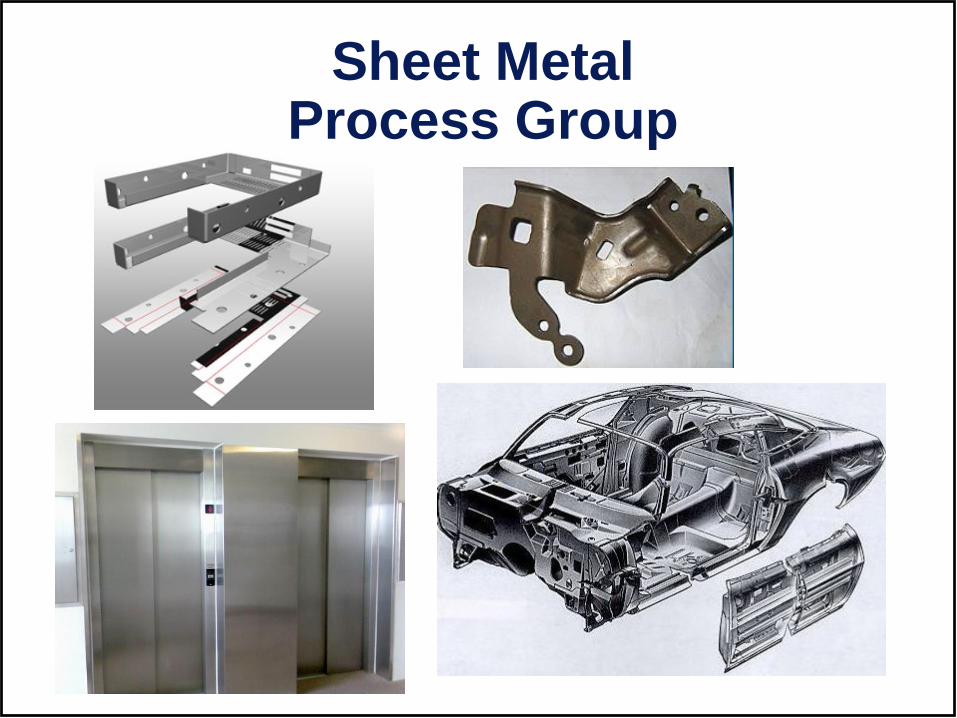
Sheet MetalProcess Group

Sheet Metal – Common Production Processes
Soft Tooling - general purpose programmable machines with low-cost expendable tooling
Hard Tooling (aka Stamping) - Processes requiring custom made high-cost molds or die sets
Laser cut [Bend Brake]Sheet Stock
Typical Routings: (as in aPriori)
Plasma cut [Bend Brake]Sheet Stock
Water Jet [Bend Brake]Sheet Stock
Turret Press [Bend Brake]Sheet Stock
Standard PressSheet Stock
Stage Tooling (aka Tandem die)Sheet Stock
Transfer PressSheet Stock
Progressive DieCoil Stock
Production
Rate
Large Stampings
(eg car Body Panels)
Small Stampings

Laser Cuting

Bend Brake (aka Press Brake)
Bend Brake Process‘Soft Tooling’ for straight bends – No Custom Tooling (ie no Hard Tooling)

Turret Press
Turret Press Process‘Soft Tooling’ for straight bends – No Custom Tooling (ie no Hard Tooling)

Bend Brake – safety!

Sheet Metal – Common Production Processes
Soft Tooling - general purpose programmable machines with low-cost expendable tooling
Hard Tooling (aka Stamping) - Processes requiring custom made high-cost molds or die sets
Laser cut [Bend Brake]Sheet Stock
Typical Routings: (as in aPriori)
Plasma cut [Bend Brake]Sheet Stock
Oxy Fuel [Bend Brake]Sheet Stock
Turret Press [Bend Brake]Sheet Stock
Standard PressSheet Stock
Stage Tooling (aka Tandem die)Sheet Stock
Transfer PressSheet Stock
Progressive DieCoil Stock
Production
Rate
Large Stampings
(eg car Body Panels)
Small Stampings

Progressive Die – coil fed, automatic, high-speed single press with multiple stations; coil strip transfers the
part

Sheet Metal - Progressive Die SetHard Tooling
Progressive Die Tool – a tool custom designed and built to produce stamped
metal parts at high speed on a Progressive Die Press (a reciprocating press)

Progressive Die in Operation – 30 ppm

Progressive Die in Operation – 100 ppm
Used for Small High-Volume Stampings

Stamping Die (i.e. Tooling)
Example

Standard Press - manual presses operated in batch mode, typically
low-to-medium volume applications

Stage Tooling – manual presses organized in a production line with
manual transfer of parts between presses (popular in low labor cost countries, non-automotive)

Manual Transfer inside a Press!

Tandem Die - manual or automatic presses organized in a production line
manual or robotic transfer of parts between presses (often a mix of manual or robotic)

Transfer Press – sheet fed, single press action with multiple dies attached to platen and transfer mechanism

Transfer Press in OperationUsed for Large High-Volume Stampings

Rapid PrototypingProcess Group

Rapid PrototypingPrinciples
SLS
SLA
3D Printing

• StereoLithography (STL)
• Selective Laser Sintering (SLS)
• Fused Deposition Modeling (FDM)
• Polyjet - 3D Printer
• Composite 3D printer
• Direct Metal Laser Sintering (DMLS) – on order
• Laminated Object Manufacturing
• Hot Plot
• Solid Ground Curing
• Light Sculpting
• Solid Creation System
• Solid Object Ultra-Violet Laser Plotting
• Computer Operated Laser Active Modeling
• Electro-Optical Systems - Stereos
Rapid Prototyping Systems

Rapid Prototyping at BMW
Cool video (click on pics)

Rapid Prototyping MechSE Ford Lab

Meet the Mark One: the world's first Carbon Fiber 3D printer ...

Stereo-Lithography Apparatus (SLA)
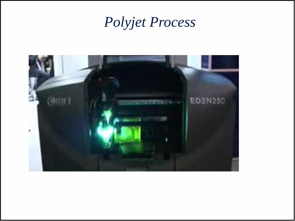
Polyjet Process
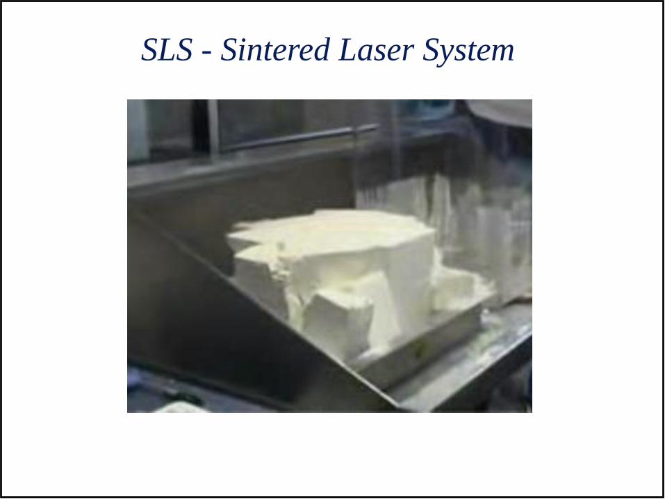
SLS - Sintered Laser System

EOS – Direct Metal Laser Sintering

3D Scanning &
FDM – Fused Deposition Modeling

STL Format: B-rep, solid object
An STL file is saved with the extension “.stl," case-
insensitive.
STL is a triangular facet based representation that
approximates surface and solid entities only. Entities such
as points, lines, curves, and attributes such as layer and
color will be ignored during the output process
An STL file consists of a list of facet data.
Each facet is uniquely identified by a unit normal (a line
perpendicular to the triangle and with a length of 1.0) and
by three vertices (corners).
The normal and each vertex are specified by three
coordinates each, so there is a total of 12 numbers stored
for each facet.

BLOCK
facet normal 0.000000e+00 -1.000000e+00 0.000000e+00
outer loop
vertex 0.000000e+00 0.000000e+00 -1.000000e+00
vertex 1.000000e+00 0.000000e+00 0.000000e+00
vertex 0.000000e+00 0.000000e+00 0.000000e+00
endloop
endfacet
facet normal 0.000000e+00 0.000000e+00 1.000000e+00
outer loop
vertex 1.000000e+00 1.000000e+00 0.000000e+00
vertex 0.000000e+00 0.000000e+00 0.000000e+00
vertex 1.000000e+00 0.000000e+00 0.000000e+00
endloop
endfacet
facet normal -1.000000e+00 0.000000e+00 0.000000e+00
outer loop
vertex 0.000000e+00 1.000000e+00 0.000000e+00
vertex 0.000000e+00 0.000000e+00 -1.000000e+00
vertex 0.000000e+00 0.000000e+00 0.000000e+00
endloop
endfacet
facet normal 0.000000e+00 0.000000e+00 1.000000e+00
outer loop
vertex 1.000000e+00 1.000000e+00 0.000000e+00
vertex 0.000000e+00 1.000000e+00 0.000000e+00
vertex 0.000000e+00 0.000000e+00 0.000000e+00
endloop
endfacet
facet normal 0.000000e+00 -1.000000e+00 0.000000e+00
outer loop
vertex 0.000000e+00 0.000000e+00 -1.000000e+00
vertex 1.000000e+00 0.000000e+00 -1.000000e+00
vertex 1.000000e+00 0.000000e+00 0.000000e+00
endloop
endfacet
facet normal 1.000000e+00 0.000000e+00 0.000000e+00
outer loop
vertex 1.000000e+00 1.000000e+00 -1.000000e+00
vertex 1.000000e+00 0.000000e+00 0.000000e+00
vertex 1.000000e+00 0.000000e+00 -1.000000e+00
endloop
endfacet
facet normal 1.000000e+00 0.000000e+00 0.000000e+00
outer loop
vertex 1.000000e+00 1.000000e+00 0.000000e+00
vertex 1.000000e+00 0.000000e+00 0.000000e+00
vertex 1.000000e+00 1.000000e+00 -1.000000e+00
endloop
endfacet
facet normal 0.000000e+00 0.000000e+00 -1.000000e+00
outer loop
vertex 0.000000e+00 1.000000e+00 -1.000000e+00
vertex 1.000000e+00 0.000000e+00 -1.000000e+00
vertex 0.000000e+00 0.000000e+00 -1.000000e+00
endloop
endfacet
facet normal 0.000000e+00 0.000000e+00 -1.000000e+00
outer loop
vertex 1.000000e+00 1.000000e+00 -1.000000e+00
vertex 1.000000e+00 0.000000e+00 -1.000000e+00
vertex 0.000000e+00 1.000000e+00 -1.000000e+00
endloop
endfacet
facet normal -1.000000e+00 0.000000e+00 0.000000e+00
outer loop
vertex 0.000000e+00 1.000000e+00 -1.000000e+00
vertex 0.000000e+00 0.000000e+00 -1.000000e+00
vertex 0.000000e+00 1.000000e+00 0.000000e+00
endloop
endfacet
facet normal 0.000000e+00 1.000000e+00 0.000000e+00
outer loop
vertex 1.000000e+00 1.000000e+00 -1.000000e+00
vertex 0.000000e+00 1.000000e+00 -1.000000e+00
vertex 0.000000e+00 1.000000e+00 0.000000e+00
endloop
endfacet
facet normal 0.000000e+00 1.000000e+00 0.000000e+00
outer loop
vertex 1.000000e+00 1.000000e+00 0.000000e+00
vertex 1.000000e+00 1.000000e+00 -1.000000e+00
vertex 0.000000e+00 1.000000e+00 0.000000e+00
endloop
endfacet
endsolid BLOCK
An Example
STL File –
Block.stl
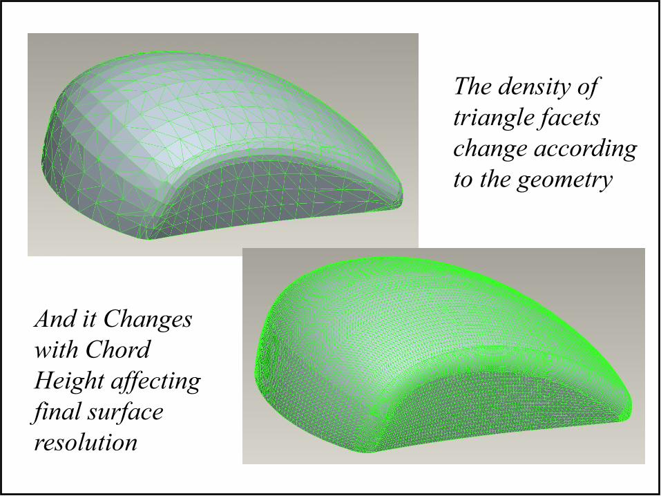
The density of
triangle facets
change according
to the geometry
And it Changes
with Chord
Height affecting
final surface
resolution

Bar and Tube Process Group

Tube/Bar Bending Processes Bend Brake (aka Press Brake)
Not suitable for Tube, only solid bar forms

Rotary Draw Bending

Rotary Draw Bending with Mandrel
Reduces crushing of inner bend radius

High Speed Wire Forming

Tube Laser Process

Rectangular/Square Tube laser cut hand bending

Rectangular/Square Tube Laser Cut - Creative Weldless Connections
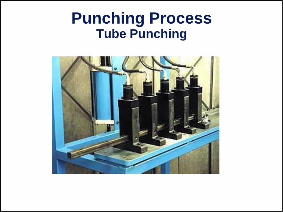
Punching Process Tube Punching

Punching Process Bar Punching

End Forming ProcessesReduction FlangingExpansion
Flattening
Chamfering
Forming
Flaring
NotchingSlotting

End Forming Video

Circular Sawing VideoMultiple Parts - Bundling

Tube/Bar Bending Processes Compression/Ram Bending

Primary Metal Casting Processes
1. Die Casting
2. Sand Casting
3. Permanent Mold Casting
4. Investment Casting

Die Casting
A non-ferrous metal is injected into a metal mold
cavity under high pressure
• Pressure is maintained during solidification, then mold is
opened and part is removed, often by robotic manipulator
• Use of high pressure to force metal into die cavity
achieves high production rates
Die Casting
Animation
Video Clip

Sand Casting – Patterns required
Pattern – a model of the part, slightly enlarged to account for shrinkage and machining allowances
Types of patterns used in sand casting:
(a) solid pattern, (b) split pattern, (c) match-plate pattern
(d) cope and drag pattern

Urbana Courthouse Clock Tower Renovation - 2009

Seth Thomas Mechanical Clock - 1876
Restoration: 2002 - 2009

Horizontal Automatic Sand Casting
• Vertical or Horizontal Mold Making Machines– 200 to 600 parts/hr
– Patterns and cores placed in by robotic device
Horizontal
Molding
Machine
video

Investment Casting (Lost Wax Process)
A pattern made of wax is coated with a refractory
material to make mold, after which wax is
melted away prior to pouring molten metal
• "Investment" comes from a less familiar
definition of "invest" - "to cover completely,"
which refers to coating of refractory material
around wax pattern
• It is a precision casting process - capable of
producing castings of high accuracy and
intricate detail
Lost Wax Video

Product Design Considerations
1. Geometric simplicity that allows for shrinkage
and reduces the need for cores.
2. Reduce sharp angles by rounding corners and
reducing stress concentrations areas that may
cause hot tearing and cracks.
3. Increase draft angles (interior and exterior).
Minimums:
– Draft = 1 for sand casting
– Draft = 2 to 3 for permanent mold processes

Draft
• Minor changes in part design can reduce need for coring
Design change to eliminate the need for using a core: (a) original design, and (b) redesign.

Product Design Considerations - Cont
4. Dimensional Tolerances and Surface Finish:
– Sand casting: poor dimensional accuracies and finish
– Die casting and investment casting: better dimensional
accuracies and finish
5. Machining Allowances:
– Additional material, called the machining allowance, is left
on the casting in those surfaces where machining is
necessary

Introduction to MachiningCommon Machining Operations
KalpakjianAka: Material Removal Processes
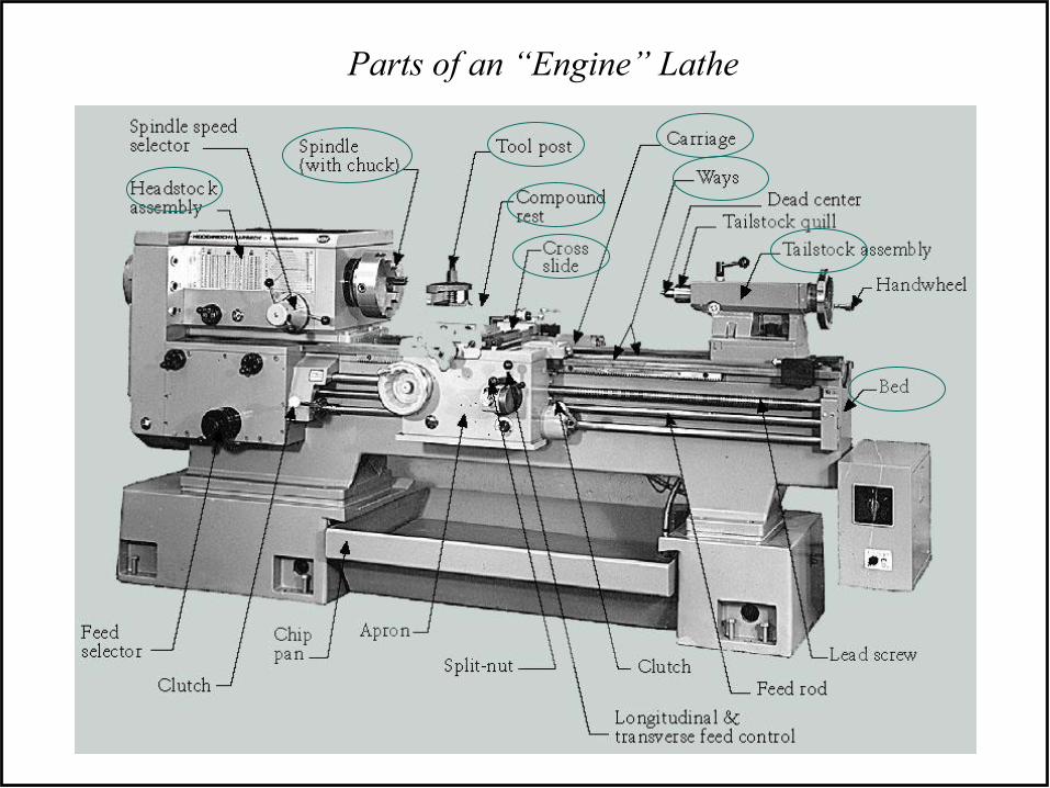
Parts of an “Engine” Lathe

www.blazingtech.netwww.ticktockpro.com
Watchmaker’s lathe Typical “Engine” Lathe
Turret Lathe Big “Engine” Lathe

www.practicalmachinist.com
Really Big “Engine” Lathes

CNC Lathe: aka “Turning Center”(carriage is mounted toward back, “upside down”)
www.machineryvalues.com
CNC = Computer Numerical Control (features are machined to size and location by a computer)

CNC MILL or “Machining Center”
Links:
CNC machining engine block from solid
Milling an Impeller